Embed Size (px)
Citation preview

Internal Report 96{08Face Recognition by Elastic Bunch Graph Matching
byLaurenz Wiskott, Jean-Marc Fellous, Norbert Kr�uger,and Christoph von der Malsburg
Ruhr-Universit�at BochumInstitut f�ur Neuroinformatik44780 Bochum IR-INI 96{08April 1996ISSN 0943-2752c 1996 Institut f�ur Neuroinformatik, Ruhr-Universit�at Bochum, FRG

This work has been submitted to the IEEE for possible publication. Copyright may be transferred withoutnotice, after which this version will be superseded.Face Recognition by Elastic Bunch Graph Matching�Laurenz Wiskott1y, Jean-Marc Fellous2z,Norbert Kr�uger1, and Christoph von der Malsburg1;21 Institut f�ur NeuroinformatikRuhr-Universit�at BochumD-44780 Bochum, Germanyhttp://www.neuroinformatik.ruhr-uni-bochum.de2 Computer Science DepartmentUniversity of Southern CaliforniaLos Angeles, CA 90089, USAApril 18, 1996AbstractWe present a system for recognizing human faces from single images out of a largedatabase with one image per person. The task is di�cult because of image variance interms of position, size, expression and pose. The system collapses most of this varianceby extracting concise face descriptions in the form of image graphs. In these, �ducialpoints on the face (eyes, mouth etc.) are described by sets of wavelet components(jets). Image graph extraction is based on a novel approach, the bunch graph, which isconstructed from a small set of sample image graphs. Recognition is based on a straight-forward comparison of image graphs. We report here on recognition experiments withgalleries of 250 images from the FERET database, also across di�erent poses.Keywords: face recognition, di�erent poses, Gabor wavelets, elastic graph matching,bunch graph, ARPA/ARL FERET database.�Supported by grants from the German Federal Ministry for Science and Technology (413-5839-01 IN 101B9) and from ARPA and the U.S. Army Research Lab (01/93/K-109).yCurrent address: Computational Neurobiology Laboratory, The Salk Institute for Biological Studies,San Diego, CA 92186-5800, http://www.cnl.salk.edu/CNL, [email protected] address: Volen Center for Complex Systems, Brandeis University, Waltham, MA 02254-9110.
1

IR-INI 96{08, c 1996 Institut f�ur Neuroinformatik, Ruhr-Universit�at Bochum, FRG 21 IntroductionWe set ourselves the task of recognizing persons from single images by reference to a gallery,which also contained only one image per person. Our problem was to address image variationdue to di�erences in head pose, position, and size and due to changing facial expression (toname only the most important). Our task is thus a typical discrimination-in-the-presence-of-variance problem, where one has to try to collapse the variance and to emphasize dis-criminating features. This is in general only possible with the help of information about thestructure of variations to be expected.Classi�cation systems di�er vastly in terms of nature and origin of their knowledge aboutimage variations. Systems in Arti�cial Intelligence and Computer Vision often stress speci�cdesigner-provided structures, for instance explicit models of three-dimensional objects or ofthe image-generation process, whereas Neural Network models tend to stress absorption ofstructure from examples with the help of statistical estimation techniques. Both of theseextremes are expensive in their own way and fall painfully short of the ease with whichnatural systems pick up essential information from just a few examples. Part of the successof natural systems must be due to general properties and laws as to how object imagestransform under natural conditions.Our system has an important core of structure which refers to images in general andto the fact that the images of coherent objects tend to translate, scale, rotate and deformelastically in the image plane. Our basic object representation is the labeled graph; edgesare labeled with distance information and nodes are labeled with wavelet responses locallybundled in jets. Stored model graphs can be matched to new images to generate imagegraphs, which can then be incorporated into a gallery and become model graphs. Waveletsas we use them are robust to moderate lighting changes and small shifts and deformations.Model graphs can easily be translated, scaled, oriented or deformed during the matchingprocess, thus compensating for a large part of the variance of the images. Unfortunately,having only one image for each person in the galleries does not provide su�cient informationto handle rotation in depth analogously. Though, we present results on recognition acrossdi�erent poses.This general structure is useful for handling any kind of coherent object and may be suf-�cient for discriminating between structurally di�erent object types. However, for in-classdiscrimination of objects, of which face recognition is an example, it is necessary to haveinformation speci�c to the structure common to all objects in the class. This is crucial forthe extraction of those structural traits from the image which are important for discrimina-tion (\to know where to look and what to pay attention to"). In our system, class-speci�cinformation has the form of bunch graphs, one for each pose, which are stacks of a moder-ate number (70 in our experiments) of di�erent faces, jet-sampled in an appropriate set of�ducial points (placed over eyes, mouth, contour etc.). Bunch graphs are treated as com-binatorial entities in that for di�erent �ducial points jets from di�erent sample faces canbe selected, thus creating a highly adaptable model. This model is matched to new facialimages in order to reliably �nd the �ducial points in the image. Jets at these points andtheir relative positions are extracted and are combined into an image graph, a representationof the face which has no remaining variation due to size, position (or in-plane orientation,not implemented here).
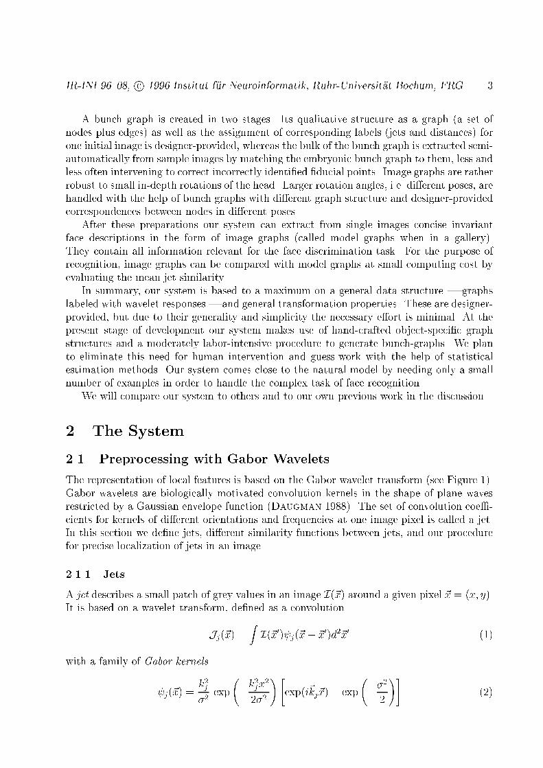
IR-INI 96{08, c 1996 Institut f�ur Neuroinformatik, Ruhr-Universit�at Bochum, FRG 3A bunch graph is created in two stages. Its qualitative structure as a graph (a set ofnodes plus edges) as well as the assignment of corresponding labels (jets and distances) forone initial image is designer-provided, whereas the bulk of the bunch graph is extracted semi-automatically from sample images by matching the embryonic bunch graph to them, less andless often intervening to correct incorrectly identi�ed �ducial points. Image graphs are ratherrobust to small in-depth rotations of the head. Larger rotation angles, i.e. di�erent poses, arehandled with the help of bunch graphs with di�erent graph structure and designer-providedcorrespondences between nodes in di�erent poses.After these preparations our system can extract from single images concise invariantface descriptions in the form of image graphs (called model graphs when in a gallery).They contain all information relevant for the face discrimination task. For the purpose ofrecognition, image graphs can be compared with model graphs at small computing cost byevaluating the mean jet similarity.In summary, our system is based to a maximum on a general data structure | graphslabeled with wavelet responses | and general transformation properties. These are designer-provided, but due to their generality and simplicity the necessary e�ort is minimal. At thepresent stage of development our system makes use of hand-crafted object-speci�c graphstructures and a moderately labor-intensive procedure to generate bunch-graphs. We planto eliminate this need for human intervention and guess-work with the help of statisticalestimation methods. Our system comes close to the natural model by needing only a smallnumber of examples in order to handle the complex task of face recognition.We will compare our system to others and to our own previous work in the discussion.2 The System2.1 Preprocessing with Gabor WaveletsThe representation of local features is based on the Gabor wavelet transform (see Figure 1).Gabor wavelets are biologically motivated convolution kernels in the shape of plane wavesrestricted by a Gaussian envelope function (Daugman 1988). The set of convolution coe�-cients for kernels of di�erent orientations and frequencies at one image pixel is called a jet.In this section we de�ne jets, di�erent similarity functions between jets, and our procedurefor precise localization of jets in an image.2.1.1 JetsA jet describes a small patch of grey values in an image I(~x) around a given pixel ~x = (x; y).It is based on a wavelet transform, de�ned as a convolutionJj(~x) = Z I(~x0) j(~x� ~x0)d2~x0 (1)with a family of Gabor kernels j(~x) = k2j�2 exp �k2jx22�2 !"exp(i~kj~x)� exp ��22 !# (2)
IR-INI 96{08, c 1996 Institut f�ur Neuroinformatik, Ruhr-Universit�at Bochum, FRG 4in the shape of plane waves with wave vector ~kj, restricted by a Gaussian envelope function.We employ a discrete set of 5 di�erent frequencies, index � = 0; :::; 4, and 8 orientations,index � = 0; :::; 7, ~kj = kjxkjy! = k� cos'�k� sin'�!; k� = 2� �+22 �; '� = ��8 ; (3)with index j = � + 8�. This sampling evenly covers a band in frequency space. The width�=k of the Gaussian is controlled by the parameter � = 2�. The second term in the bracketof (2) makes the kernels DC-free, i.e. the integral R j(~x)d2~x vanishes. One speaks of awavelet transform since the family of kernels is self-similar, all kernels being generated fromone mother wavelet by dilation and rotation.Gabor wavelets jet
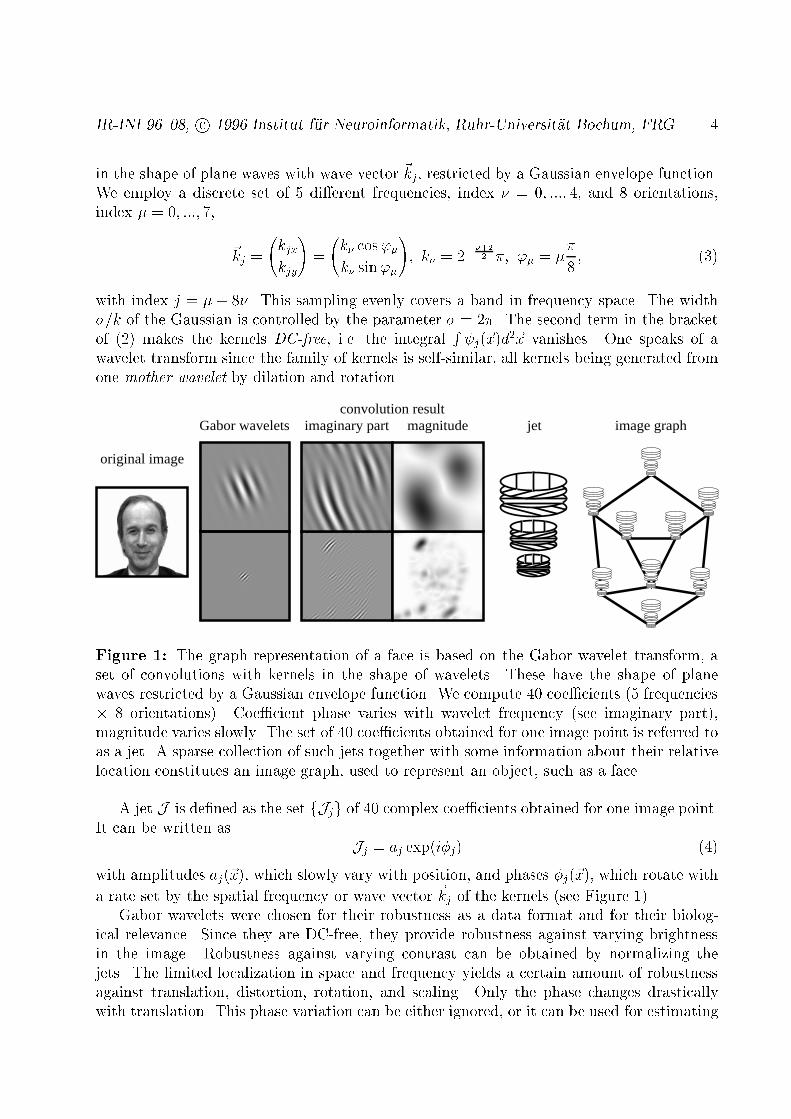
original image
convolution resultmagnitudeimaginary part image graph
Figure 1: The graph representation of a face is based on the Gabor wavelet transform, aset of convolutions with kernels in the shape of wavelets. These have the shape of planewaves restricted by a Gaussian envelope function. We compute 40 coe�cients (5 frequencies� 8 orientations). Coe�cient phase varies with wavelet frequency (see imaginary part),magnitude varies slowly. The set of 40 coe�cients obtained for one image point is referred toas a jet. A sparse collection of such jets together with some information about their relativelocation constitutes an image graph, used to represent an object, such as a face.A jet J is de�ned as the set fJjg of 40 complex coe�cients obtained for one image point.It can be written as Jj = aj exp(i�j) (4)with amplitudes aj(~x), which slowly vary with position, and phases �j(~x), which rotate witha rate set by the spatial frequency or wave vector ~kj of the kernels (see Figure 1).Gabor wavelets were chosen for their robustness as a data format and for their biolog-ical relevance. Since they are DC-free, they provide robustness against varying brightnessin the image. Robustness against varying contrast can be obtained by normalizing thejets. The limited localization in space and frequency yields a certain amount of robustnessagainst translation, distortion, rotation, and scaling. Only the phase changes drasticallywith translation. This phase variation can be either ignored, or it can be used for estimating

IR-INI 96{08, c 1996 Institut f�ur Neuroinformatik, Ruhr-Universit�at Bochum, FRG 5displacement, as will be shown later. A disadvantage of the large kernels is their sensitivityto background variations. It was shown, however, that if the object contour is known thein uence of the background can be suppressed (P�otzsch 1994). Finally, the Gabor waveletshave similar shape as the receptive �elds of simple cells found in the visual cortex of verte-brate animals (Pollen & Ronner 1981; Jones & Palmer 1987; DeValois & DeValois1988).2.1.2 Comparing JetsDue to phase rotation, jets taken from image points only a few pixels from each other havevery di�erent coe�cients, although representing almost the same local feature. This cancause severe problems for matching. We therefore either ignore the phase or compensate forits variation explicitly. The similarity functionSa(J ;J 0) = Pj aja0jrPj a2j Pj a02j ; (5)already used by Buhmann et al. (1992) and Lades et al. (1993), ignores the phase com-pletely. With a jet J taken at a �xed image position and jets J 0 = J 0(~x) taken at variableposition ~x, Sa(J ;J 0(~x)) is a smooth function with local optima forming large attractorbasins (see Figure 2a), leading to rapid and reliable convergence with simple search methodssuch as gradient descent or di�usion.
-1
-0.5
0
0.5
1
-40 -20 0 20 40horizontal displacement [pixels]
similarity without phase (a)similarity with phase (b)
estimated displacement / 8 (c)
Figure 2: a) Similarity Sa(J (~x1);J 0(~x0))with jet J 0 taken from the left eye of theface shown in Figure 1, and jet J takenfrom pixel positions of the same horizon-tal line, ~x1 = ~x0 + (dx; 0); dx = �50; :::; 50(The image in Figure 1 has a width of128 pixels). The similarity potential issmooth and has a large attractor basin.b) Similarity S�(J (~x1);J 0(~x0)) and c) es-timated displacement ~d(J (~x1);J 0(~x0)) forthe same jets as in a (using focus 1). Thesimilarity potential has many more localoptima. The right eye is 24 pixels awayfrom the left eye, generating a local maxi-mum for both similarity functions close todx = �24. The estimated displacement isprecise around the 0-position and rougherat other local optima, especially at theother eye. (The displacement values aredivided by 8 to �t the ordinate range.)

IR-INI 96{08, c 1996 Institut f�ur Neuroinformatik, Ruhr-Universit�at Bochum, FRG 6Using phase has two potential advantages. Firstly, phase information is required todiscriminate between patterns with similar amplitudes, should they occur, and secondly,since phase varies so quickly with location, it provides a means for accurate jet localizationin an image. Assuming that two jets J and J 0 refer to object locations with small relativedisplacement ~d, the phase shifts can approximately be compensated for by the terms ~d~kj,leading to a phase-sensitive similarity functionS�(J ;J 0) = Pj aja0j cos(�j � �0j � ~d~kj)rPj a2j Pj a02j : (6)In order to compute it, the displacement ~d has to be estimated. This can be done bymaximizing S� in its Taylor expansion, as explained in the following section. It is actually agreat advantage of this second similarity function that it yields this displacement information.Pro�les of similarities and estimated displacements are shown in Figure 2.2.1.3 Displacement EstimationIn order to estimate the displacement vector ~d = (dx; dy), we have adopted a method usedfor disparity estimation (Theimer & Mallot 1994) based on (Fleet & Jepson 1990).The idea is to maximize the similarity S� in its Taylor expansion:S�(J ;J 0) � Pj aja0j[1� 0:5(�j � �0j � ~d~kj)2]rPj a2j Pj a02j : (7)Setting @@dxS� = @@dyS� = 0 and solving for ~d leads to~d(J ;J 0) = dxdy ! = 1�xx�yy � �xy�yx � �yy ��yx��xy �xx ! �x�y ! ; (8)if �xx�yy � �xy�yx 6= 0, with �x = Xj aja0jkjx(�j � �0j);�xy = Xj aja0jkjxkjy;and �y;�xx;�yx;�yy de�ned correspondingly.This equation yields a straightforward method for estimating the displacement or dispar-ity between two jets taken from object locations close enough that their Gabor kernels arehighly overlapping. Without further modi�cations, this equation can determine displace-ments up to half the wavelength of the highest frequency kernel, which would be two pixelsfor k0 = �=2. The range can be increased by using low frequency kernels only. For thelargest kernels the estimated displacement may be 8 pixels. One can then proceed withthe next higher frequency level and re�ne the result, possibly by correcting the phases ofthe higher frequency coe�cients by multiples of 2� according to the displacement estimated

IR-INI 96{08, c 1996 Institut f�ur Neuroinformatik, Ruhr-Universit�at Bochum, FRG 7on the lower frequency level. We refer to the number of frequency levels used for the �rstdisplacement estimation as focus. A focus of 1 indicates that only the lowest frequency levelis used and that the estimated displacement may be up to 8 pixels. A focus of 5 indicatesthat all �ve levels are used, and the disparity may only be up to 2 pixels. In any case, all�ve levels are eventually used in the iterative re�nement process described above.If one has access to the whole image of jets, one can also work iteratively. Assume a jetJ is to be accurately positioned in the neighborhood of point ~x0 in an image. ComparingJ with the jet J0 = J (~x0) yields an estimated displacement of ~d0 = ~d(J ;J (~x0)). Then ajet J1 is taken from position ~x1 = ~x0 + ~d0 and the displacement is estimated again. Butsince the new location is closer to the correct position, the new displacement ~d1 will besmaller and can be estimated more accurately with a higher focus, converging eventually tosubpixel accuracy. We have used this iterative scheme in the matching process described inSection 2.3.2.2 Face Representation2.2.1 Individual FacesFor faces, we have de�ned a set of �ducial points, e.g. the pupils, the corners of the mouth,the tip of the nose, the top and bottom of the ears, etc. A labeled graph G representing aface consists of N nodes on these �ducial points at positions ~xn; n = 1; :::; N and E edgesbetween them. The nodes are labeled with jets Jn. The edges are labeled with distances�~xe = ~xn�~xn0 ; e = 1; :::; E, where edge e connects node n0 with n. Hence the edge labels aretwo-dimensional vectors. (When wanting to refer to the geometrical structure of a graph,unlabeled by jets, we call it a grid.) This face graph is object-adapted, since the nodes areselected from face-speci�c points (�ducial points, see Figure 4).Graphs for di�erent head pose di�er in geometry and local features. Although the �ducialpoints refer to corresponding object locations, some may be occluded, and jets as well asdistances vary due to rotation in depth. To be able to compare graphs for di�erent poses,we manually de�ned pointers to associate corresponding nodes in the di�erent graphs.2.2.2 Face Bunch GraphsIn order to �nd �ducial points in new faces, one needs a general representation rather thanmodels of individual faces. This representation should cover a wide range of possible varia-tions in the appearance of faces, such as di�erently shaped eyes, mouths, or noses, di�erenttypes of beards, variations due to gender, age and race, etc. It is obvious that it would betoo expensive to cover each feature combination by a separate graph. We instead combine arepresentative set of individual model graphs into a stack-like structure, called a face bunchgraph (FBG) (see Figure 3). Each model has the same grid structure and the nodes refer toidentical �ducial points. A set of jets referring to one �ducial point is called a bunch. Aneye bunch, for instance, may include jets from closed, open, female, and male eyes etc. tocover these local variations. During the location of �ducial points in a face not seen before,the procedure described in the next section selects the best �tting jet, called the local expert,from the bunch dedicated to each �ducial point. Thus, the full combinatorics of jets in the

IR-INI 96{08, c 1996 Institut f�ur Neuroinformatik, Ruhr-Universit�at Bochum, FRG 8bunch graph is available, covering a much larger range of facial variation than representedin the constituting model graphs themselves.Assume for a particular pose there are M model graphs GBm (m = 1; :::;M) of identicalstructure, taken from di�erent model faces. The corresponding FBG B then is given thesame structure, its nodes are labeled with bunches of jets J Bmn and its edges are labeledwith the averaged distances �~xBe = Pm �~xBme =M .
face bunch graph
Figure 3: The Face Bunch Graph (FBG) serves asa representation of faces in general. It is designed tocover all possible variations in the appearance of faces.The FBG combines information from a number of facegraphs. Its nodes are labeled with sets of jets, calledbunches, and its edges are labeled with averages ofdistance vectors. During comparison to an image thebest �tting jet in each bunch is selected independently,indicated by grey shading.2.3 Generating Face Representations by Elastic Bunch GraphMatchingSo far we have only described how individual faces and general knowledge about faces arerepresented by labeled graphs and the FBG, respectively. We are now going to explain howthese graphs are generated. The simplest method is to do so manually, by marking a setof �ducial points for a given image and letting edge labels be computed as the di�erencesbetween node positions. Finally the Gabor wavelet transform provides the jets for the nodes.We have used this manual method to generate initial graphs for the system, one for eachpose, together with pointers to indicate which pairs of nodes in graphs for di�erent posescorrespond to each other.If the system has a FBG (possibly consisting of one model only), graphs for new imagescan automatically be generated by Elastic Bunch Graph Matching. Initially, when the FBGcontains only few faces, it is necessary to review and correct the resulting matches, butonce the FBG is rich enough (approximately 70 graphs) one can rely on the matching andgenerate large galleries of model graphs automatically.

IR-INI 96{08, c 1996 Institut f�ur Neuroinformatik, Ruhr-Universit�at Bochum, FRG 92.3.1 The Graph Similarity FunctionA key role in Elastic Bunch Graph Matching (EBGM) is played by a function evaluating thegraph similarity between an image graph and the FBG of identical pose. It depends on thejet similarities and the distortion of the image grid relative to the FBG grid. For an imagegraph GI with nodes n = 1; :::; N and edges e = 1; :::; E and a FBG B with model graphsm = 1; :::;M the similarity is de�ned asSB(GI;B) = 1N Xn maxm �S�(J In ;J Bmn )�� �E Xe (�~xIe ��~xBe )2(�~xBe )2 ; (9)where � determines the relative importance of jets and metric structure. Jn are the jets atnode n and �~xe are the distance vectors used as labels at edges e. Since the FBG providesseveral jets for each �ducial point, the best one is selected and used for comparison. Thesebest �tting jets serve as local experts for the image face.2.3.2 Matching ProcedureThe goal of EBGM on a probe image is to �nd the �ducial points and thus to extract fromthe image a graph that maximizes the similarity with the FBG. In practice, one has to applya heuristic algorithm to come close to the optimum within reasonable time. We use a coarseto �ne approach. The matching schedule described here assumes normalized face images ofknown pose such that only one FBG is required. The more general case of varying size issketched in the next section.Stage 1 Find approximate face position: Condense the FGB into an average graph by takingthe average amplitude of the jets in each bunch of the FBG (or, alternatively, selectone arbitrary graph as a representative). Use this as a rigid model (� = 1) andevaluate its similarity at each location of a square lattice with a spacing of 4 pixels.At this stage the similarity function Sa without phase is used instead of S�. Repeatthe scanning around the best �tting position with a spacing of 1 pixel. The best�tting position �nally serves as starting point for the next stage.Stage 2 Re�ne position and estimate size: Now the FBG is used without averaging, varyingit in position and size. Check the four di�erent positions (�3;�3) pixels displacedfrom the position found in Stage 1, and at each position check two di�erent sizeswhich have the same center position, a factor of 1:18 smaller or larger than the FBGaverage size. This is without e�ect on the metric similarity, since the vectors ~xBe aretransformed accordingly. We still keep � =1. For each of these eight variations thebest �tting jet for each node is selected and its displacement according to Equation 8is computed. This is done with a focus of 1, i.e., the displacements may be of amagnitude up to eight pixels. The grids are then rescaled and repositioned in orderto minimize the square sum over the displacements. Keep the best of the eightvariations as starting point for the next stage.Stage 3 Re�ne size and �nd aspect ratio: A similar relaxation process as described for Stage2 is applied, relaxing, however, the x- and y-dimensions independently. In addition,the focus is increased successively from 1 to 5.
IR-INI 96{08, c 1996 Institut f�ur Neuroinformatik, Ruhr-Universit�at Bochum, FRG 10Stage 4 Local distortion: In a pseudo-random sequence the position of each individual imagenode is varied in order to further increase the similarity to the FBG. Now the metricsimilarity is taken into account by setting � = 2 and using the vectors ~xBe as obtainedin Stage 3. In this stage only those positions are considered for which the estimateddisplacement vector is small (d < 1, see Equation 8). For this local distortion thefocus again increases from 1 to 5.The resulting graph is called the image graph and is stored as a representation for theindividual face of the image.
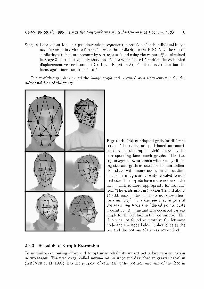
Figure 4: Object-adapted grids for di�erentposes. The nodes are positioned automati-cally by elastic graph matching against thecorresponding face bunch graphs. The twotop images show originals with widely di�er-ing size and grids as used for the normaliza-tion stage with many nodes on the outline.The other images are already rescaled to nor-mal size. Their grids have more nodes on theface, which is more appropriate for recogni-tion (The grids used in Section 3.2 had about14 additional nodes which are not shown herefor simplicity). One can see that in generalthe matching �nds the �ducial points quiteaccurately. But mismatches occurred for ex-ample for the left face in the bottom row. Thechin was not found accurately; the leftmostnode and the node below it should be at thetop and the bottom of the ear respectively.2.3.3 Schedule of Graph ExtractionTo minimize computing e�ort and to optimize reliability we extract a face representationin two stages. The �rst stage, called normalization stage and described in greater detail in(Kr�uger et al. 1995), has the purpose of estimating the position and size of the face in

IR-INI 96{08, c 1996 Institut f�ur Neuroinformatik, Ruhr-Universit�at Bochum, FRG 11the original image, so that the image can be scaled and cut to standard size. The secondstage takes this image as input and extracts a precise image graph appropriate for facerecognition purposes. The two stages di�er in emphasis. The �rst one has to deal withgreater uncertainty as to size and position of the head and has to optimize the reliabilitywith which it �nds the face, but there is no need to �nd �ducial points with any precision orextract data important for face recognition. The second stage can start with little uncertaintyas to position and size of the head but has to extract a detailed face graph with high precision.In the experiments described below, original images had a format of 256�384 pixels, andthe faces varied in size by a factor of three (see Figure 4). The poses were given and needednot to be determined. The normalization stage used three FBGs of appropriate pose whichdi�er in face size. We somewhat arbitrarily picked approximately 30 images to form eachFBG. More careful selection of images to cover a wider range of variations can only improvesystem performance. The grids used in the construction of the FBGs put little emphasis(i.e., few nodes) on the interior of the face and have fewer nodes than those used for thesecond stage, see Figure 4 for two examples. The smaller number of nodes speeds the processof face �nding. Using an EBGM scheme similar to the one described in Section 2.3.2 wematch each of the three FBGs to the input image. We select the graph that matches best,cut a frame of appropriate size around it from the image and resize it to 128�128 pixels.The poses could be determined analogously (Kr�uger et al. 1996), but here the poses areassumed to be known. In our experiments, normalization took approximately 20 secondson a SPARCstation 10-512 with a 50 MHz processor and identi�ed face position and scalecorrectly in approximately 99% of the images.The second stage uses the matching procedure exactly as described in Section 2.3.2,starting the match at standard size and position. The face bunch graphs used in this stagehave more nodes, which we have placed in positions which we believe are important for personidenti�cation, emphasizing the interior of the face. Each of the three principal poses (frontal,half-pro�le, and pro�le; left-facing poses are ipped to right-facing poses) is matched witha di�erent grid structure and with a di�erent FBG, formed by using 70 arbitrarily chosenimages. This stage took approximately 10 seconds.2.4 RecognitionAfter having extracted model graphs from the gallery images and image graphs from theprobe images, recognition is possible with relatively little computational e�ort, by comparingan image graph to all model graphs and picking the one with the highest similarity value.The similarity function we use here for comparing graphs is an average over the similaritiesbetween pairs of corresponding jets. For image and model graphs referring to di�erent pose,we compare jets according to the manually provided correspondences. If GI is the imagegraph, GM the model graph, and if node nn0 in the model graph corresponds to node n0 inthe image graph, we de�ne graph similarity as:SG(GI;GM) = 1N 0 Xn0 Sa(J In0;JMnn0 ); (10)where the sum runs only over the N 0 nodes in the image graph with a correspondent inthe model graph. We use the jet similarity function without phase here. It turned out to
IR-INI 96{08, c 1996 Institut f�ur Neuroinformatik, Ruhr-Universit�at Bochum, FRG 12be more discriminative, possibly because it is more robust with respect to change in facialexpression and other variations. We here ignore the jet distortions created by rotation indepth, but will take up the subject in a later paper.This graph similarity induces a ranking of the model graphs relative to an image graph.A person is recognized correctly if the correct model yields the highest graph similarity, i.e.,if it is of rank one. A con�dence criterion on how reliably a person is recognized can easilybe derived from the statistics of the ranking (see Lades et al. 1993). However, we haverestricted our results to unquali�ed recognition rates, which already give a good impressionof system performance.3 Experiments3.1 DatabaseThe image galleries we used in our experiments are taken from the ARPA/ARL FERETdatabase provided by the US Army Research Laboratory. That database explicitly distin-guishes di�erent poses, and images are labeled with pose identity. These poses are: frontal,half-pro�le right or left (rotated by about 40-70 degrees), and pro�le right or left (see Figure 5for examples). For most faces there are two frontal views with di�erent facial expression.Apart from a few exceptions there are no disguises, variations in hairstyle or in clothing. Thebackground is always a homogeneous light or grey, except for smoothly varying shadows. Thesize of the faces varies by about a factor of three (but is constant for each individual, infor-mation which we could have used to improve recognition rates, but didn't). The format ofthe original images is 256�384 pixels. Inquiries about the database should be directed toJonathon Phillips (e-mail:[email protected] or [email protected]).3.2 ResultsWe used various model and probe galleries with faces of di�erent pose. Each gallery con-tained 250 faces with just one image per person. We relied on the explicitly labeled poseidentity instead of using our own pose recognition capability. Recognition results are shownin Table 1.The very high correct recognition rate for frontal against frontal images (�rst row) inspite of the variation in facial expression and the slight variations in pose shows the greatpotential of our system. However, all images were taken in single sessions, such that lightingconditions are very similar from picture to picture and hairstyle and clothing are identical.Further work will have to show the degree of robustness against greater image variation.Initial experiments are encouragingBefore comparing left against right poses we ipped all right pose images over. Sincehuman heads are bilaterally symmetric to some degree and since at least our present systemperforms poorly on rotation in depth (see below) we proceeded under the expectation thatit would be easier to deal with di�erences due to facial asymmetry than with di�erencescaused by substantial head rotation. This assumption is born out at least by the highrecognition rate of 84% for right pro�le against left pro�le (third row). The sharply reduced
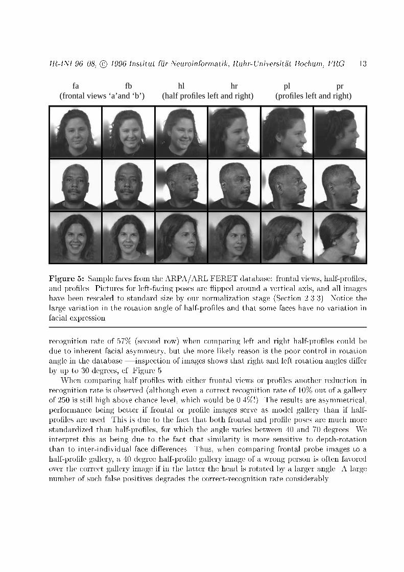
IR-INI 96{08, c 1996 Institut f�ur Neuroinformatik, Ruhr-Universit�at Bochum, FRG 13(profiles left and right)(frontal views ‘a’and ‘b’) (half profiles left and right)
fa fb hl hr pl pr
Figure 5: Sample faces from the ARPA/ARL FERET database: frontal views, half-pro�les,and pro�les. Pictures for left-facing poses are ipped around a vertical axis, and all imageshave been rescaled to standard size by our normalization stage (Section 2.3.3). Notice thelarge variation in the rotation angle of half-pro�les and that some faces have no variation infacial expression.recognition rate of 57% (second row) when comparing left and right half-pro�les could bedue to inherent facial asymmetry, but the more likely reason is the poor control in rotationangle in the database | inspection of images shows that right and left rotation angles di�erby up to 30 degrees, cf. Figure 5.When comparing half pro�les with either frontal views or pro�les another reduction inrecognition rate is observed (although even a correct recognition rate of 10% out of a galleryof 250 is still high above chance level, which would be 0.4%!). The results are asymmetrical,performance being better if frontal or pro�le images serve as model gallery than if half-pro�les are used. This is due to the fact that both frontal and pro�le poses are much morestandardized than half-pro�les, for which the angle varies between 40 and 70 degrees. Weinterpret this as being due to the fact that similarity is more sensitive to depth-rotationthan to inter-individual face di�erences. Thus, when comparing frontal probe images to ahalf-pro�le gallery, a 40 degree half-pro�le gallery image of a wrong person is often favoredover the correct gallery image if in the latter the head is rotated by a larger angle. A largenumber of such false positives degrades the correct-recognition rate considerably.

IR-INI 96{08, c 1996 Institut f�ur Neuroinformatik, Ruhr-Universit�at Bochum, FRG 14Model Probe First rank First 10 ranksgallery images # % # %250 fa 250 fb 245 98 248 99250 hr 181 hl 103 57 147 81250 pr 250 pl 210 84 236 94249 fa + 1 fb 171 hl + 79 hr 44 18 111 44171 hl + 79 hr 249 fa + 1 fb 42 17 95 38170 hl + 80 hr 217 pl + 33 pr 22 9 67 27217 pl + 33 pr 170 hl + 80 hr 31 12 80 32Table 1: Recognition results for cross-runs between di�erent galleries (f: frontal views; a, b:expression a and b; h: half pro�les; p: pro�les; l, r: left and right). Each gallery containedonly one image per person; the di�erent compositions in the four bottom lines are due tothe fact that not for all persons all poses were available. Given are numbers on how oftenthe correct model was identi�ed as rank one and how often it was among the �rst 10 (4%).4 DiscussionThe system we describe is general and exible. It is designed for an in-class recognition task,i.e. for recognizing members of a known class of objects. We have applied it to face recognitionbut the system is in no way specialized to faces and it can be directly applied to other in-class recognition tasks, such as recognizing individuals of a given animal species, given thesame level of standardization of the images. In contrast to many neural network systems, noextensive training for new faces or new object classes is required. Only a moderate numberof typical examples have to be inspected to build up a bunch graph, and individuals canthen be recognized after storing a single image.The performance is high on faces of same pose. Robustness against rotation in depthup to about 20 degrees has already been demonstrated with a previous version of the sys-tem (Lades et al. 1993). The constraint of working with single images deprives the systemfrom information necessary for invariance to rotation in depth. Therefore the system perfor-mance in recognizing people in unfamiliar poses is signi�cantly degraded. It is known frompsychophysical experiments that also human subjects perform poorly on this task. Bruceet al. (1987) have shown that reliability on judging whether two unfamiliar faces are thesame degrades signi�cantly with depth rotation angle. In the absence of easily distinguishedfeatures such as hairstyle, beard or glasses a similar result was obtained by Kalocsai et al.(1994).4.1 Comparison to Previous WorkIn comparison to the system (Lades et al. 1993) on the basis of which we have developed thesystem presented here we have made several major modi�cations. We now utilize waveletphase information for relatively precise node localizations, which could be used as an addi-tional recognition cue (though topography is not used at all in the recognition step of thecurrent system) | previously, node localization had been rather imprecise. We have intro-

IR-INI 96{08, c 1996 Institut f�ur Neuroinformatik, Ruhr-Universit�at Bochum, FRG 15duced the potential to specialize the system to speci�c object types and to handle di�erentposes with the help of object-adapted grids. These improvements and the introduction of theFace Bunch Graph makes it possible to extract from images sparse and largely variance-freestructural descriptions in the form of image graphs, which reliably refer to �ducial pointson the object. This accelerates recognition from large databases considerably since for eachprobe image data variance needs to be searched only once instead of in each attemptedmatch to a gallery image, as was previously necessary. The ability of the new system torefer to object-�xed �ducial points irrespective of pose represents an advantage in itself andis essential for some interesting graph operations (cf. Section 4.3).There is a considerable literature on face recognition, and many di�erent techniques havebeen applied to the task (see Samal & Iyengar 1992; Valentin et al. 1994 for reviews).Many systems are based on user de�ned face-speci�c features. Yuille (1991), for ex-ample, represents eyes by a circle within an almond-shape and de�nes an energy functionto optimize a total of 9 model parameters for matching it to an image. Brunelli & Pog-gio (1993) similarly employ speci�c models for eyebrows, nose, mouth, etc. and derive 35geometrical features such as eyebrow thickness, nose width, mouth width, and eleven radiidescribing the chin shape. The drawback of these systems is that the features as well as theprocedures to extract them must be de�ned and programmed by the user for each objectclass again, and the system has no means to adapt to samples for which the features fail.For example, the eye models mentioned above may fail for faces with sun glasses or haveproblems if the eyes are closed, or chin radii cannot be extracted if the face is bearded. Inthese cases the user has to design new features and new algorithms to extract them. Withthis type of approach, the system can never be weaned from designer intervention. Our sys-tem, in contrast, can be taught exceptional cases, such as sun glasses or beards, or entirelynew object classes, by the presentation of examples and incorporation into bunch graphs.The still necessary designer intervention to craft appropriate grids will soon be replaced byautomatic methods, see below.An approach to face recognition also avoiding user de�ned features is based on PrincipalComponent Analysis (PCA) (Sirovich & Kirby 1987; Kirby & Sirovich 1990; Turk& Pentland 1991; O'Toole et al. 1993). In this approach, faces are �rst aligned witheach other and then treated as high-dimensional pixel vectors from which eigenvectors, so-called eigenfaces, are computed, together with the corresponding eigenvalues. A probe faceis decomposed with respect to these eigenvectors and is e�ciently represented by a smallnumber, say 30, of expansion coe�cients. (The necessary image alignment can be doneautomatically within the PCA framework, see Turk & Pentland 1991). PCA is optimalwith respect to data compression and seems to be successful for recognition purposes. In itsoriginal, simple form, PCA treats an entire face as one vector. It is then sensitive to partialocclusion or to object deformation. This problem has been dealt with by treating small imageregions centered on �ducial points (eyes, nose, mouth) as additional pixel vectors from whichto extract more features by PCA (Pentland et al. 1994). These �ducial regions can easilybe located by matching subspaces of a few PCs to the image. The PCA approach in thisform and our approach begin to look very similar: A graph of �ducial points, labeled withexample-derived feature vectors (small sets of eigenvalues in the PCA approach, bunchesof jets in our approach) is matched to the image, and the optimally matching \grid" isused to extract a structural description from the image. Recognition is then based on this.
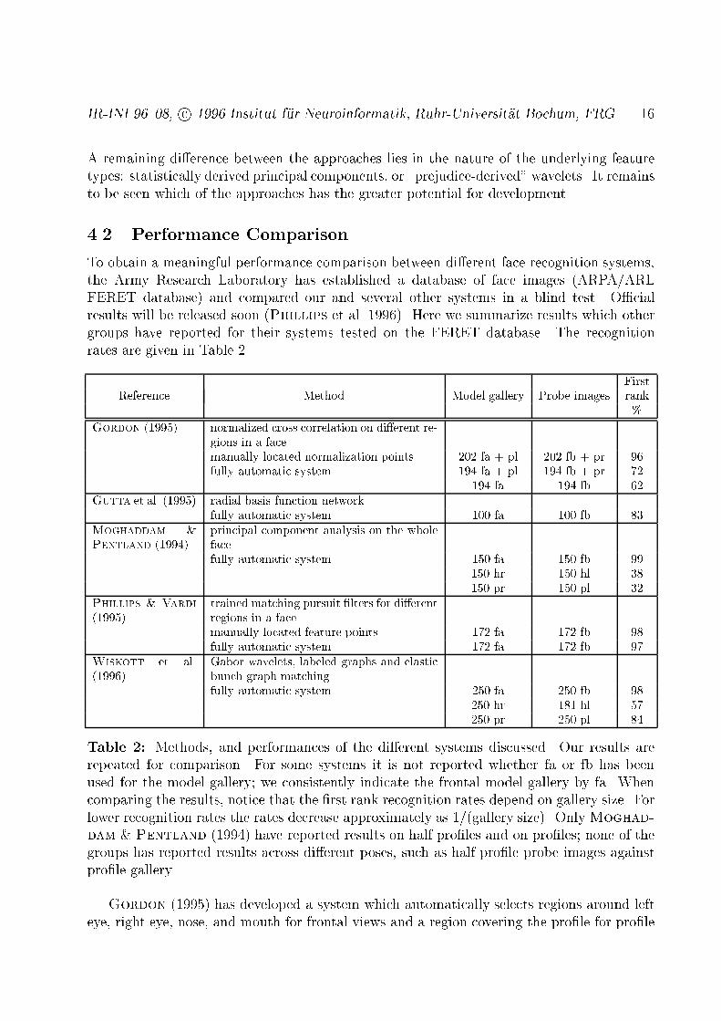
IR-INI 96{08, c 1996 Institut f�ur Neuroinformatik, Ruhr-Universit�at Bochum, FRG 16A remaining di�erence between the approaches lies in the nature of the underlying featuretypes: statistically derived principal components, or \prejudice-derived" wavelets. It remainsto be seen which of the approaches has the greater potential for development.4.2 Performance ComparisonTo obtain a meaningful performance comparison between di�erent face recognition systems,the Army Research Laboratory has established a database of face images (ARPA/ARLFERET database) and compared our and several other systems in a blind test. O�cialresults will be released soon (Phillips et al. 1996). Here we summarize results which othergroups have reported for their systems tested on the FERET database. The recognitionrates are given in Table 2. FirstReference Method Model gallery Probe images rank%Gordon (1995) normalized cross correlation on di�erent re-gions in a facemanually located normalization points 202 fa + pl 202 fb + pr 96fully automatic system 194 fa + pl 194 fb + pr 72194 fa 194 fb 62Gutta et al. (1995) radial basis function networkfully automatic system 100 fa 100 fb 83Moghaddam &Pentland (1994) principal component analysis on the wholefacefully automatic system 150 fa 150 fb 99150 hr 150 hl 38150 pr 150 pl 32Phillips & Vardi(1995) trained matching pursuit �lters for di�erentregions in a facemanually located feature points 172 fa 172 fb 98fully automatic system 172 fa 172 fb 97Wiskott et al.(1996) Gabor wavelets, labeled graphs and elasticbunch graph matchingfully automatic system 250 fa 250 fb 98250 hr 181 hl 57250 pr 250 pl 84Table 2: Methods, and performances of the di�erent systems discussed. Our results arerepeated for comparison. For some systems it is not reported whether fa or fb has beenused for the model gallery; we consistently indicate the frontal model gallery by fa. Whencomparing the results, notice that the �rst rank recognition rates depend on gallery size. Forlower recognition rates the rates decrease approximately as 1/(gallery size). OnlyMoghad-dam & Pentland (1994) have reported results on half pro�les and on pro�les; none of thegroups has reported results across di�erent poses, such as half pro�le probe images againstpro�le gallery.Gordon (1995) has developed a system which automatically selects regions around lefteye, right eye, nose, and mouth for frontal views and a region covering the pro�le for pro�le

IR-INI 96{08, c 1996 Institut f�ur Neuroinformatik, Ruhr-Universit�at Bochum, FRG 17views. The faces are then normalized for scale and rotation. The recognition is based onnormalized cross correlation of these �ve regions as compared to reference models. Resultsare given on the fully automatic system, also for frontal views only, and on a system wherethe normalization points, i.e. pupil centers, nose and chin tip, are selected by hand. For thecombined gallery (fa + pl) there is a great di�erence between the performance of the fullyautomatic system and that with manually located normalization points. That indicates thatthe automatic location of the normalization points is the main weakness of this system.Gutta et al. (1995) have collected the images for the FERET database. They havetested the performance of a standard RBF (radial basis function) network and a systembased on geometrical relationships between facial features, such as eyes, nose, mouth etc.The performance of the latter is very low and not summarized in Table 2.Moghaddam & Pentland (1994) present results based on the PCA approach discussedin the previous section. A front-end system normalizes the faces with respect to translation,scale, lighting, contrast, as well as slight rotations in the image plane. The face images arethen decomposed with respect to the �rst eigenvectors and the corresponding coe�cients areused for face representation and comparison. The performance on frontal views, which arehighly standardized, is high and comparable to that of our system, but the performance onhalf pro�les and pro�les is relatively low. That indicates that the global PCA-approach ismore sensitive to variations such as rotation in depth or varying hairstyle.Phillips & Vardi (1995) have trained two sets of matching pursuit �lters for the tasksof face location and identi�cation. The �lters focus on di�erent regions: the interior of theface, the eyes, and the nose for location; tip of the nose, bridge of the nose, left eye, righteye, and interior of the face for identi�cation. The performance is high and comparable tothat of our system. The small performance di�erence between the fully automatic systemand the identi�cation module indicates that the location module works reliably.In the following section we discuss some methods which can potentially or have beenshown to further improve the performance of our system. A detailed analysis of our basicsystem and some of these extensions will be given by Lyons et al. (1996).4.3 Further DevelopmentsThe newly introduced features of the system open various possibilities to improve the systemfurther. Especially the ability to reliably �nd surface points on an object can be useful, forinstance when the issue is learning about local object properties (Shams & Spoelstra1996). One such local property is di�erential degree of robustness against disturbances.Kr�uger et al. have developed a system for learning weights emphasizing the more discrim-inative nodes (Kr�uger 1995; Kr�uger et al. 1996). On model galleries of size 130{150 andprobe images of di�erent pose an average improvement of the �rst rank recognition rates of6% was achieved, from 25% without to 31% with weights on average. Another individualtreatment of the nodes has been developed by Maurer & von der Malsburg (1995).They applied linear jet transformations to compensate for the e�ect of rotation in depth. Ona frontal pose gallery of 90 faces and half pro�le probe images an average improvement ofthe �rst rank recognition rate of 15% was achieved, from 36% without rotation to 50% and53% with rotation, depending on witch pose was rotated. However, linear transformation isobviously not su�cient, and one may have to train and apply more general transformations.
IR-INI 96{08, c 1996 Institut f�ur Neuroinformatik, Ruhr-Universit�at Bochum, FRG 18By using phase information and the FBGs, matching accuracy has improved signi�cantly.However, many partial mismatches still occur. This is probably due to the primitive waygraph topography is handled, distortions being controlled by independent elastic stretchingof node-to-node vectors. It would be of great help if these many degrees of freedom werereplaced by just the few parameters necessary to describe typical global distortion patterns,due, for instance, to rotation in depth, variation in facial expression or hairstyle, or to theregular and symmetrical face shape variations from person to person or with age. Thesewould have to be learned from examples, of course. Better deformation models would yieldinformation on the type of disturbance, which would be of value in itself, and improverecognition. Some research in this direction has, for example, been done by Lanitis et al.(1995). When determined with su�cient reliability, graph topography can itself be used asa basis for recognition (cf. Brunelli & Poggio 1993).In (Wiskott 1996) the bunch graph technique has been used to fairly reliably determinefacial attributes from single images, such as gender or the presence of glasses or a beard. Ifthis technique was developed to extract independent and stable personal attributes, such asage, skin color, hair type or again gender, recognition from large databases could be improvedand speeded considerably by preselecting corresponding sectors of the database.If the restriction to single probe and gallery images were relaxed and several images ora brief video sequence could be inspected, the system could be enriched with informationon depth pro�le and on di�erent poses. The merging of di�erent poses into a coherentrepresentation and the recognition of objects on this basis in a pose-independent way hasbeen demonstrated in (von der Malsburg & Reiser 1995). Depth-pro�le informationcould be added to individual nodes as discriminatory feature to improve recognition directlyand it could be used to predict poses not previously seen.The manual de�nition of appropriate grid structures and semi-autonomous process ofbunch graph acquisition will have to be replaced by an autonomous process. Automaticreduction of a FBG to its essential jets in the bunches has been demonstrated by Kr�ugeret al. (1996). The creation of a new bunch graph is most easily based on image sequences,which contain many cues for grouping, segmentation, and detecting correspondences. Thegrouping of nodes for salient points on the basis of common motion has been demonstratedin (Manjunath et al. 1992). Monitoring a rotating object by continuously applying EBGMcan then reveal which nodes refer to corresponding �ducial points in di�erent poses (cf.von der Malsburg & Reiser 1995; Maurer & von der Malsburg 1996). In aboot-strapping fashion, object-speci�c grids and object bunch graphs could be establishedby starting with a crude or general grid, such as utilized in (Lades et al. 1993), to �rstrecognize object classes and establish approximate correspondences between images withina class, on the basis of which more object-speci�c grids and bunch graphs could be formedin stages, a little bit reminiscent of the way in which we �nd precise image graphs in twostages here.AcknowledgementsWe wish to thank Irving Biederman, Ladan Shams, Michael Lyons, and Thomas Maurer forvery fruitful discussions and their help in evaluating the performance of the system. Thanks

IR-INI 96{08, c 1996 Institut f�ur Neuroinformatik, Ruhr-Universit�at Bochum, FRG 19goes to Thomas Maurer also for reviewing and optimizing the code. We acknowledge helpfulcomments on the manuscript by Jonathon Phillips. For the experiments we have used theFERET database of facial images collected under the ARPA/ARL FERET program.ReferencesBruce, V., Valentine, T., and Baddeley, A. (1987). The basis of the 3/4 viewadvantage in face recognition. Applied Cognitive Psychology, 1:109{120.Brunelli, R. and Poggio, T. (1993). Face recognition: Features versus templates. IEEETransactions on Pattern Analysis and Machine Intelligence, 15(10):1042{1052.Buhmann, J., Lange, J., von der Malsburg, C., Vorbr�uggen, J. C., and W�urtz,R. P. (1992). Object recognition with Gabor functions in the dynamic link architec-ture: Parallel implementation on a transputer network. In Kosko, B., editor, NeuralNetworks for Signal Processing, pages 121{159. Prentice Hall, Englewood Cli�s, NJ07632.Daugman, J. G. (1988). Complete discrete 2-D Gabor transform by neural networks forimage analysis and compression. IEEE Transactions on Acoustics, Speech and SignalProcessing, 36(7):1169{1179.DeValois, R. L. and DeValois, K. K. (1988). Spatial Vision. Oxford Press.Fleet, D. J. and Jepson, A. D. (1990). Computation of component image velocity fromlocal phase information. International Journal of Computer Vision, 5(1):77{104.Gordon, G. G. (1995). Face recognition from frontal and pro�le views. In Bichsel, M.,editor, Proceedings of the International Workshop on Automatic Face- and Gesture-Recognition, IWAFGR, pages 47{52, Zurich.Gutta, S., Huang, J., Singh, D., Shah, I., Takacs, B., and Wechsler, H. (1995).Benchmark studies on face recognition. In Bichsel, M., editor, Proceedings of theInternational Workshop on Automatic Face- and Gesture-Recognition, IWAFGR, pages227{231, Zurich.Jones, J. and Palmer, L. (1987). An evaluation of the two dimensional Gabor �lter modelof simple receptive �elds in cat striate cortex. J. of Neurophysiology, 58:1233{1258.Kalocsai, P., Biederman, I., and Cooper, E. E. (1994). To what extent can the recog-nition of unfamiliar faces be accounted for by a representation of the direct output ofsimple cells. In Proceedings of the Association for Research in Vision and Ophtalmology,ARVO, Sarasota, Florida.Kirby, M. and Sirovich, L. (1990). Application of the Karhunen-Lo�eve procedure for thecharacterization of human faces. IEEE Transactions on Pattern Analysis and MachineIntelligence, 12(1):103{108.

IR-INI 96{08, c 1996 Institut f�ur Neuroinformatik, Ruhr-Universit�at Bochum, FRG 20Kr�uger, N. (1995). Learning weights in discrimination functions using a priori constraints.In Sagerer, G., S.Posch, and Kummert, F., editors,Mustererkennung 1995, pages110{117. Springer Verlag.Kr�uger, N., P�otzsch, M., and von der Malsburg, C. (1995). Face �nding with alearned representation based on labeled graphs. Submitted to IEEE Transactions onNeural Networks.Kr�uger, N., P�otzsch, M., and von der Malsburg, C. (1996). Determination of faceposition and pose with a learned representation based on labeled graphs. Submitted toIEEE Transactions on Neural Networks.Lades, M., Vorbr�uggen, J. C., Buhmann, J., Lange, J., von der Malsburg, C.,W�urtz, R. P., and Konen, W. (1993). Distortion invariant object recognition inthe dynamic link architecture. IEEE Transactions on Computers, 42(3):300{311.Lanitis, A., Taylor, C. J., and Cootes, T. F. (1995). An automatic face identi�cationsystem using exible appearance models. Image and Vision Computing, 13(5):393{401.Lyons, M., Shams, L., Maurer, T., Wiskott, L., Fellous, J.-M., Kr�uger, N.,and von der Malsburg, C. (1996). Performance of the eidos face recognition systemin the FERET competition. In preparation.Manjunath, B. S., Chellappa, R., and von der Malsburg, C. (1992). A featurebased approach to face recognition. Technical Report CAR-TR-604 or CS-TR-2834,Computer Vision Laboratory, University of Maryland, Colledge Park, MD 20742{3411.Maurer, T. and von der Malsburg, C. (1995). Linear feature transformations torecognize faces rotated in depth. In Proceedings of the International Conference onArti�cial Neural Networks, ICANN'95, pages 353{358, Paris.Maurer, T. and von der Malsburg, C. (1996). Tracking and learning graphs onimage sequences of faces. Submitted to the International Conference on Arti�cial NeuralNetworks ICANN'96, Bochum.Moghaddam, B. and Pentland, A. (1994). Face recognition using view-based and mod-ular eigenspaces. In Proc. SPIE Conference on Automatic Systems for the Identi�cationand Inspection of Humans, volume SPIE 2277, pages 12{21.O'Toole, A. J., Abdi, H., Deffenbacher, K. A., and Valentin, D. (1993). Low-dimensional representation of faces in higher dimensions of the face space. Journal ofthe Optical Society of America A, 10(3):405{411.Pentland, A., Moghaddam, B., and Starner, T. (1994). View-based and modulareigenspaces for face recognition. In IEEE Proc. Computer Vision and Pattern Recogni-tion, pages 84{91.

IR-INI 96{08, c 1996 Institut f�ur Neuroinformatik, Ruhr-Universit�at Bochum, FRG 21Phillips, P. J., Rauss, P., and Der, S. (1996). FERET (face recognition technol-ogy) recognition algorithm development and test report. Technical report, U.S. ArmyResearch Laboratory.Phillips, P. J. and Vardi, Y. (1995). Data driven methods in face recognition. InBichsel, M., editor, Proceedings of the International Workshop on Automatic Face-and Gesture-Recognition, IWAFGR, pages 65{70, Zurich.Pollen, D. A. and Ronner, S. F. (1981). Phase relationship between adjacent simplecells in the visual cortex. Science, 212:1409{1411.P�otzsch, M. (1994). Die Behandlung der Wavelet-Transformation von Bildern in derN�ahe von Objektkanten. Technical Report IR-INI 94-04, Institut f�ur Neuroinformatik,Ruhr-Universit�at Bochum, D-44780 Bochum, Germany. Diploma thesis.Samal, A. and Iyengar, P. A. (1992). Automatic recognition and analysis of humanfaces and facial expressions: A survey. Pattern Recognition, 25(1):65{77.Shams, L. and Spoelstra, J. (1996). Learning Gabor-based features for face detection.Submitted to World Congress on Neural Networks '96.Sirovich, L. and Kirby, M. (1987). Low-dimensional procedure for the characterizationof human faces. Journal of the Optical Society of America A, 4(3):519{524.Theimer, W. M. and Mallot, H. A. (1994). Phase-based binocular vergence control anddepth reconstruction using active vision. CVGIP: Image Understanding, 60(3):343{358.Turk, M. and Pentland, A. (1991). Eigenfaces for recognition. Journal of CognitiveNeuroscience, 3(1):71{86.Valentin, D., Abdi, H., O'Toole, A. J., and Cottrell, G. W. (1994). Connectionistmodels of face processing: A survey. Pattern Recognition, 27(9):1209{1230.von der Malsburg, C. and Reiser, K. (1995). Pose invariant object recognition ina neural system. In Proceedings of the International Conference on Arti�cial NeuralNetworks ICANN'95, pages 127{132, Paris. EC2 & Cie.Wiskott, L. (1996). Phantom faces for face analysis. Technical Report IR-INI 96-06,Institut f�ur Neuroinformatik, Ruhr-Universit�at Bochum, D-44780 Bochum, Germany.Submitted to Pattern Recognition.Yuille, A. L. (1991). Deformable templates for face recognition. Journal of CognitiveNeuroscience, 3(1):59{70.