Embed Size (px)
Citation preview
Installation Manual
ACEDVio0516.p65 2003/05/16, 21:451
Notices and Warranties
2
Notic
es &
Warrantie
s
Copyright RegulationsCopyright RegulationsCopyright RegulationsCopyright RegulationsCopyright RegulationsIt is illegal for anyone to violate any of the rights provided by the copyright laws to theowner of copyright, except for fair use (mainly private noncommercial use).Also, in certain casescopying is prohibited with no exceptions. In no event shall Canopus be liable for any direct orindirect damages whatsoever arising from the use of captured materials.
WWWWWarrantyarrantyarrantyarrantyarrantyYour ACEDVio options are covered by a limited warranty when you register your Canopus product. This warranty is for a period of three years from the date of purchase from Canopus or anauthorized Canopus agent. This warranty applies only to the original purchaser of the Canopusproduct and is not transferable. Canopus Corporation warrants that for this period the productwill be in good working order.Should our product fail to be in good working order, Canopus will, at its option, repair or replace itat no additional charge, provided that the product has not been subjected to misuse, abuse ornon-Canopus authorized alterations, modifications and/or repair.Proof of purchase is required to validate your warranty.Canopus is not responsible for any lost profits, lost savings or other incidental or consequentialdamages arising out of the use of, or inability to use, this product. This includes damage toproperty and, to the extent permitted by law, damages for personal injury. This warranty isin lieu of all other warranties of merchantability and fitness for a particular purpose.
CautionsCautionsCautionsCautionsCautionsPlease observe the following cautions when using this product. If you have any questionsregarding the method of usage, the descriptions herein, or any other concerns, please contactthe your local canopus office or distributor.
ACEDVio0516.p65 2003/05/16, 21:452

Notices and Warranties
3
Notic
es &
Warrantie
s
DANGERDANGERDANGERDANGERDANGERThe following conditions indicate the potential for serious bodily injury or loss of life.
Health precautionsHealth precautionsHealth precautionsHealth precautionsHealth precautionsIn rare cases, flashing lights or stimulation from the bright light of a computer monitor displaymay trigger temporary epileptic seizures or loss of consciousness. It is believed that evenindividuals whom have never experienced such symptoms may be susceptible.If you or close relatives have experienced any of these symptoms, consult a doctor beforeusing this product.
Do not use in environments requiring a high degree ofDo not use in environments requiring a high degree ofDo not use in environments requiring a high degree ofDo not use in environments requiring a high degree ofDo not use in environments requiring a high degree ofreliability and safetyreliability and safetyreliability and safetyreliability and safetyreliability and safetyThis product is not to be used in medical devices or life support systems. The characteristicsof this product are not suited for use with such systems.
Protect against static electricityProtect against static electricityProtect against static electricityProtect against static electricityProtect against static electricityAn electrostatic discharge may damage components of this product. Do not directly touchany of the connectors or component surfaces.Static electricity can be generated on clothing and on people. Before handling the product,discharge static electricity from your body by touching a grounded metal surface.
CAUTIONCAUTIONCAUTIONCAUTIONCAUTIONThe following conditions indicate the potential for bodily harm, damage to hardware orloss of data.
Do not setup other than the Described methodDo not setup other than the Described methodDo not setup other than the Described methodDo not setup other than the Described methodDo not setup other than the Described methodDo not setup in a manner other than described. Do not use while wrapped in cloth or plastic.Heat can accumulate, causing burns, fire or damage.
ACEDVio0516.p65 2003/05/16, 21:463
Notices and Warranties
4
Notic
es &
Warrantie
s
FCC NoticeFCC NoticeFCC NoticeFCC NoticeFCC NoticeThis equipment has been tested and found to comply with the limits for the class B digitaldevice, pursuant to part 15 of the FCC Rules. These limits are designed to provide reasonableprotection against interference in a residential installation.This equipment generates, uses and can radiate radio frequency energy and if not installedand used in accordance with the instructions, may cause harmful interference to radiocommunications. However, there is no guarantee that interference will not occur in a particularinstallation. If this equipment does cause harmful interference to radio or television reception,which can be determined by turning the equipment off and on, the user is encouraged to tryand correct the interference by one or more of the following measures:
• Reorient or relocate the receiving antenna.• Increase the separation between the equipment and receiver.• Connect the equipment into an outlet on a circuit different from that to which the
receiver is connected.• Consult the dealer or an experienced radio/TV technician for help.
Declaration of ConformityDeclaration of ConformityDeclaration of ConformityDeclaration of ConformityDeclaration of Conformity
According to FCC Part 15Responsible Party Name: Canopus Co.,Ltd.
Address: 1-2-2 Murotani Nishi-ku, Kobe-city Hyogo 651-2241 JapanTelephone: +81-78-992-4404
Declares that productModel: ACEDVioComplies with Part 15 of the FCC Rules.
ACEDVio0516.p65 2003/05/16, 21:464
Chapter 1Chapter 1Chapter 1Chapter 1Chapter 1Hardware InstallationHardware InstallationHardware InstallationHardware InstallationHardware Installation
ACEDVio0516.p65 2003/05/16, 21:465
Hardware Installation
6
Ch1:H
ard
ware
Insta
llatio
n
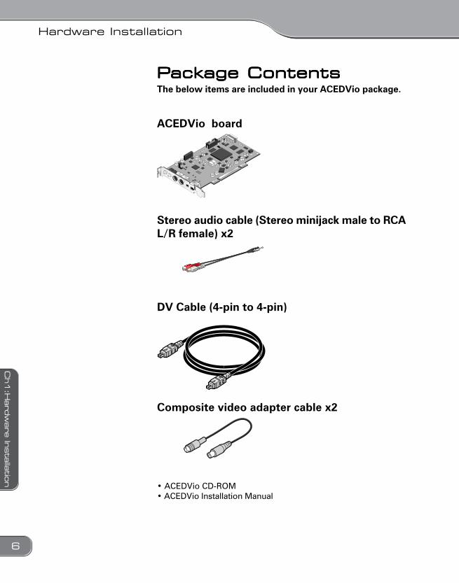
PPPPPackackackackackage Contentsage Contentsage Contentsage Contentsage ContentsThe below items are included in your ACEDVio package.
ACEDVio board
Stereo audio cable (Stereo minijack male to RCAL/R female) x2
DV Cable (4-pin to 4-pin)
Composite video adapter cable x2
• ACEDVio CD-ROM• ACEDVio Installation Manual
ACEDVio0516.p65 2003/05/16, 21:466
Hardware Installation
7
Ch1:H
ard
ware
Insta
llation
Connectors and functionsConnectors and functionsConnectors and functionsConnectors and functionsConnectors and functions
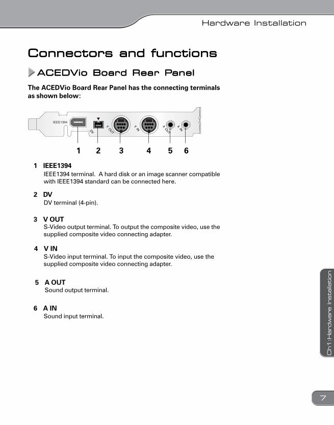
ACEDVio Board Rear PACEDVio Board Rear PACEDVio Board Rear PACEDVio Board Rear PACEDVio Board Rear Panelanelanelanelanel
The ACEDVio Board Rear Panel has the connecting terminalsas shown below:
1 2 3 4 5 6
1 IEEE1394IEEE1394 terminal. A hard disk or an image scanner compatiblewith IEEE1394 standard can be connected here.
2 DVDV terminal (4-pin).
3 V OUTS-Video output terminal. To output the composite video, use thesupplied composite video connecting adapter.
4 V INS-Video input terminal. To input the composite video, use thesupplied composite video connecting adapter.
5 A OUTSound output terminal.
6 A INSound input terminal.
ACEDVio0516.p65 2003/05/16, 21:467
Hardware Installation
8
Ch1:H
ard
ware
Insta
llatio
n
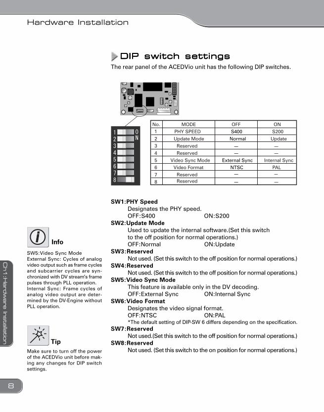
DIP switch settingsDIP switch settingsDIP switch settingsDIP switch settingsDIP switch settingsThe rear panel of the ACEDVio unit has the following DIP switches.
No. MODE OFF ONPHY SPEED S400 S200Update Mode Normal Update
ReservedReserved
Video Sync Mode External Sync Internal SyncVideo Format NTSC PAL
ReservedReserved
1
23
456
87
SW1:PHY SpeedDesignates the PHY speed.OFF:S400 ON:S200
SW2:Update ModeUsed to update the internal software.(Set this switchto the off position for normal operations.)OFF:Normal ON:Update
SW3:ReservedNot used. (Set this switch to the off position for normal operations.)
SW4:ReservedNot used. (Set this switch to the off position for normal operations.)
SW5:Video Sync ModeThis feature is available only in the DV decoding.OFF:External Sync ON:Internal Sync
SW6:Video FormatDesignates the video signal format.OFF:NTSC ON:PAL*The default setting of DIP-SW 6 differs depending on the specification.
SW7:ReservedNot used.(Set this switch to the off position for normal operations.)
SW8:ReservedNot used. (Set this switch to the on position for normal operations.)Make sure to turn off the power
of the ACEDVio unit before mak-ing any changes for DIP switchsettings.
Tip
Info
SW5:Video Sync ModeExternal Sync: Cycles of analogvideo output such as frame cyclesand subcarrier cycles are syn-chronized with DV stream’s framepulses through PLL operation.Internal Sync: Frame cycles ofanalog video output are deter-mined by the DV-Engine withoutPLL operation.
ACEDVio0516.p65 2003/05/16, 21:468
Hardware Installation
9
Ch1:H
ard
ware
Insta
llation
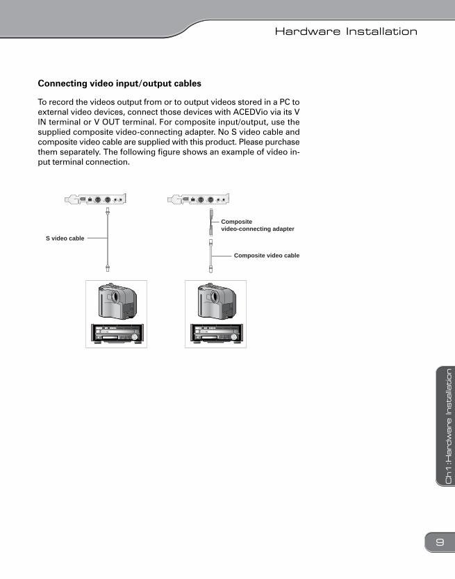
To record the videos output from or to output videos stored in a PC toexternal video devices, connect those devices with ACEDVio via its VIN terminal or V OUT terminal. For composite input/output, use thesupplied composite video-connecting adapter. No S video cable andcomposite video cable are supplied with this product. Please purchasethem separately. The following figure shows an example of video in-put terminal connection.
Composite video cable
Composite video-connecting adapter
S video cable
Connecting video input/output cables
ACEDVio0516.p65 2003/05/16, 21:469
Hardware Installation
10
Ch1:H
ard
ware
Insta
llatio
n
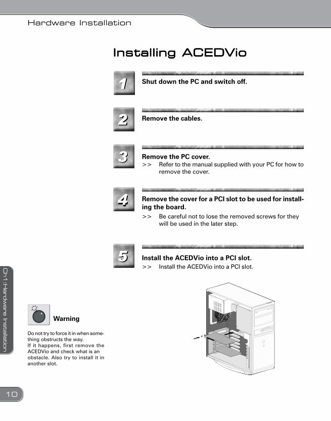
Installing ACEDVioInstalling ACEDVioInstalling ACEDVioInstalling ACEDVioInstalling ACEDVio
11
22
33
44
55
Shut down the PC and switch off.
Remove the cables.
Remove the PC cover.>> Refer to the manual supplied with your PC for how to
remove the cover.
Remove the cover for a PCI slot to be used for install-ing the board.>> Be careful not to lose the removed screws for they
will be used in the later step.
Install the ACEDVio into a PCI slot.>> Install the ACEDVio into a PCI slot.
Do not try to force it in when some-thing obstructs the way.If it happens, first remove theACEDVio and check what is anobstacle. Also try to install it inanother slot.
Warning
ACEDVio0516.p65 2003/05/16, 21:4610
Hardware Installation
11
Ch1:H
ard
ware
Insta
llation
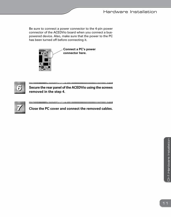
Be sure to connect a power connector to the 4-pin powerconnector of the ACEDVio board when you connect a bus-powered device. Also, make sure that the power to the PChas been turned off before connecting it.
Connect a PC’s powerconnector here.
66
77
Secure the rear panel of the ACEDVio using the screwsremoved in the step 4.
Close the PC cover and connect the removed cables.
ACEDVio0516.p65 2003/05/16, 21:4711
Hardware Installation
12
Ch1:H
ard
ware
Insta
llatio
n
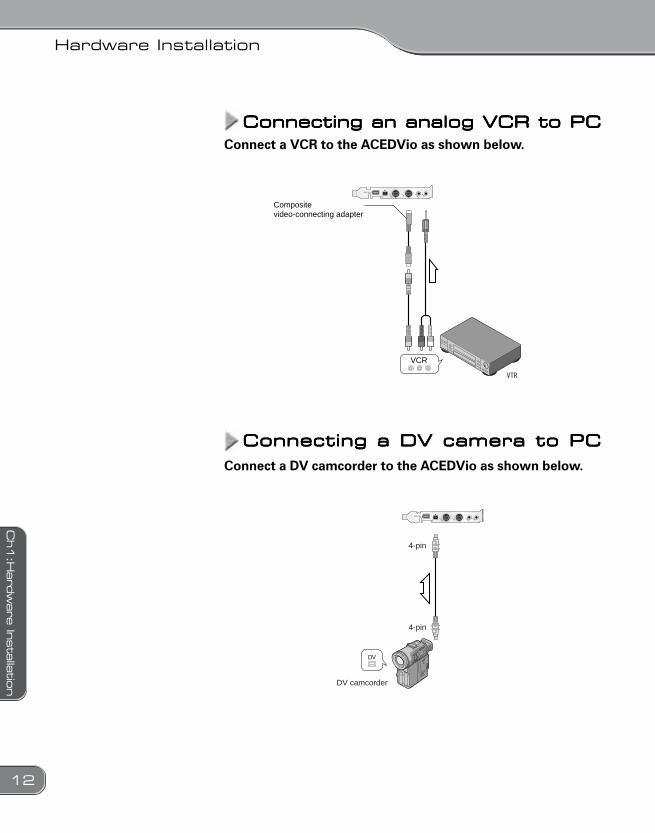
Connecting an analog VCR to PCConnecting an analog VCR to PCConnecting an analog VCR to PCConnecting an analog VCR to PCConnecting an analog VCR to PC
Connecting a DV camera to PCConnecting a DV camera to PCConnecting a DV camera to PCConnecting a DV camera to PCConnecting a DV camera to PC
VCR
Composite video-connecting adapter
4-pin
4-pin
DV camcorder
Connect a VCR to the ACEDVio as shown below.
Connect a DV camcorder to the ACEDVio as shown below.
ACEDVio0516.p65 2003/05/16, 21:4712
Hardware Installation
13
Ch1:H
ard
ware
Insta
llation
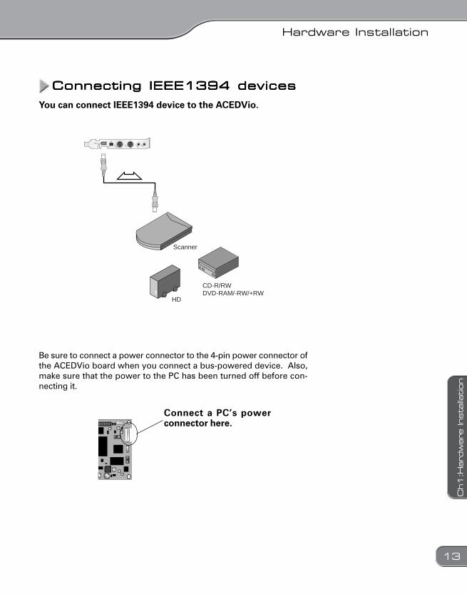
Connecting IEEE1394 devicesConnecting IEEE1394 devicesConnecting IEEE1394 devicesConnecting IEEE1394 devicesConnecting IEEE1394 devices
You can connect IEEE1394 device to the ACEDVio.
Scanner
HD
CD-R/RWDVD-RAM/-RW/+RW
Be sure to connect a power connector to the 4-pin power connector ofthe ACEDVio board when you connect a bus-powered device. Also,make sure that the power to the PC has been turned off before con-necting it.
Connect a PC’s powerconnector here.
ACEDVio0516.p65 2003/05/16, 21:4713
Hardware Installation
14
Ch1:H
ard
ware
Insta
llatio
n
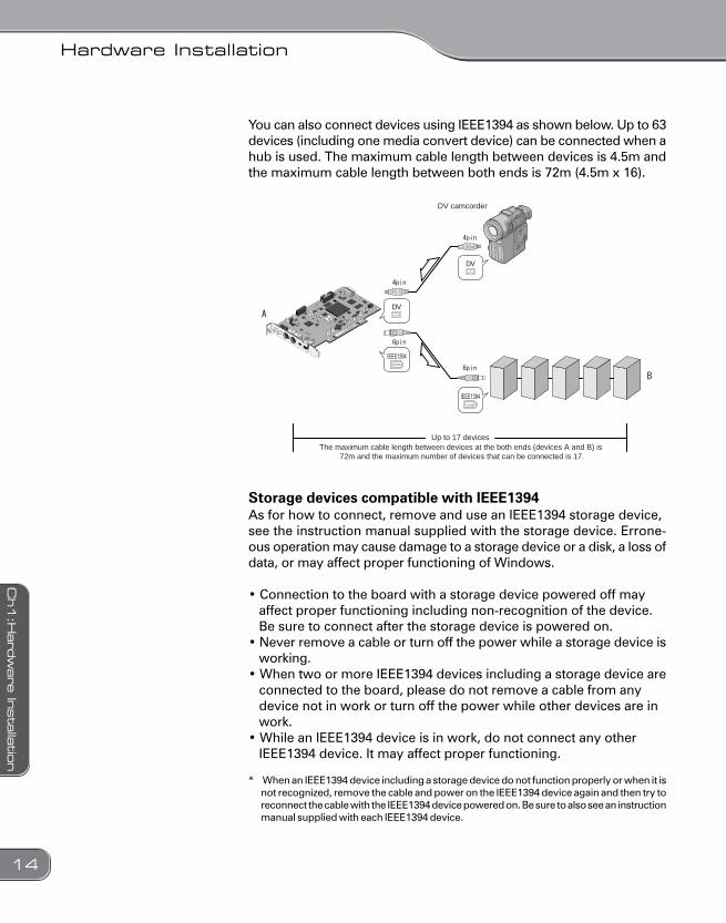
You can also connect devices using IEEE1394 as shown below. Up to 63devices (including one media convert device) can be connected when ahub is used. The maximum cable length between devices is 4.5m andthe maximum cable length between both ends is 72m (4.5m x 16).
DV camcorder
Up to 17 devicesThe maximum cable length between devices at the both ends (devices A and B) is
72m and the maximum number of devices that can be connected is 17.
Storage devices compatible with IEEE1394As for how to connect, remove and use an IEEE1394 storage device,see the instruction manual supplied with the storage device. Errone-ous operation may cause damage to a storage device or a disk, a loss ofdata, or may affect proper functioning of Windows.
• Connection to the board with a storage device powered off mayaffect proper functioning including non-recognition of the device.Be sure to connect after the storage device is powered on.
• Never remove a cable or turn off the power while a storage device isworking.
• When two or more IEEE1394 devices including a storage device areconnected to the board, please do not remove a cable from anydevice not in work or turn off the power while other devices are inwork.
• While an IEEE1394 device is in work, do not connect any otherIEEE1394 device. It may affect proper functioning.
* When an IEEE1394 device including a storage device do not function properly or when it isnot recognized, remove the cable and power on the IEEE1394 device again and then try toreconnect the cable with the IEEE1394 device powered on. Be sure to also see an instructionmanual supplied with each IEEE1394 device.
ACEDVio0516.p65 2003/05/16, 21:4714
Chapter 2Chapter 2Chapter 2Chapter 2Chapter 2Software InstallationSoftware InstallationSoftware InstallationSoftware InstallationSoftware Installation
ACEDVio0516.p65 2003/05/16, 21:4715
Software Installation
16
Ch2:S
oftw
are
Insta
llatio
n
11
Confirming the driver installationConfirming the driver installationConfirming the driver installationConfirming the driver installationConfirming the driver installation
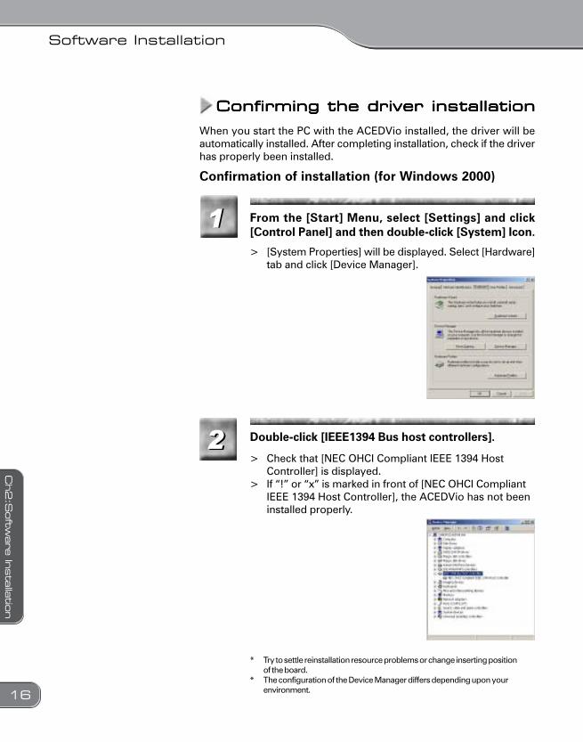
When you start the PC with the ACEDVio installed, the driver will beautomatically installed. After completing installation, check if the driverhas properly been installed.
Confirmation of installation (for Windows 2000)
From the [Start] Menu, select [Settings] and click[Control Panel] and then double-click [System] Icon.
> [System Properties] will be displayed. Select [Hardware]tab and click [Device Manager].
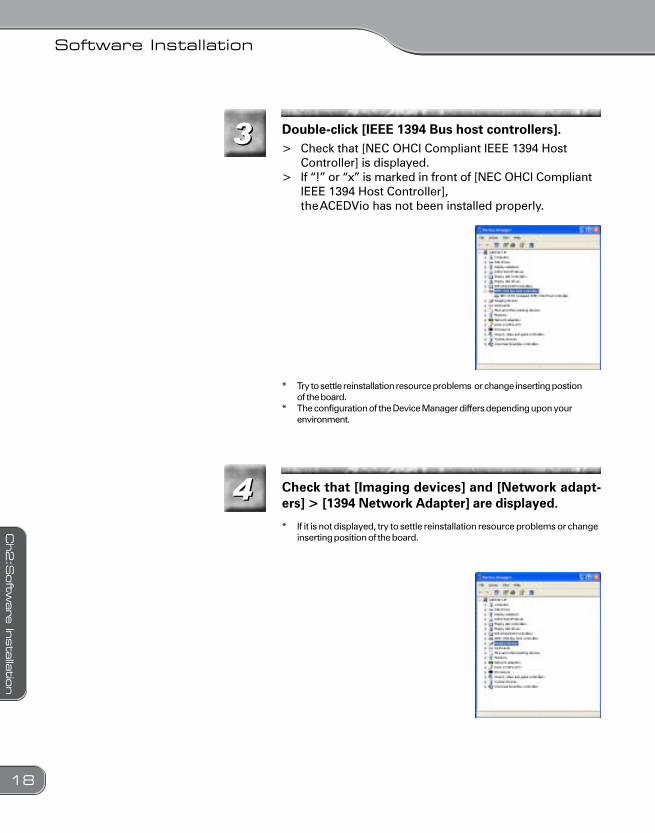
Double-click [IEEE1394 Bus host controllers].
> Check that [NEC OHCI Compliant IEEE 1394 HostController] is displayed.
> If “!” or “x” is marked in front of [NEC OHCI CompliantIEEE 1394 Host Controller], the ACEDVio has not beeninstalled properly.
* Try to settle reinstallation resource problems or change inserting positionof the board.
* The configuration of the Device Manager differs depending upon yourenvironment.
22
ACEDVio0516.p65 2003/05/16, 21:4716
Software Installation
17
Ch2:S
oftw
are
Insta
llation
22
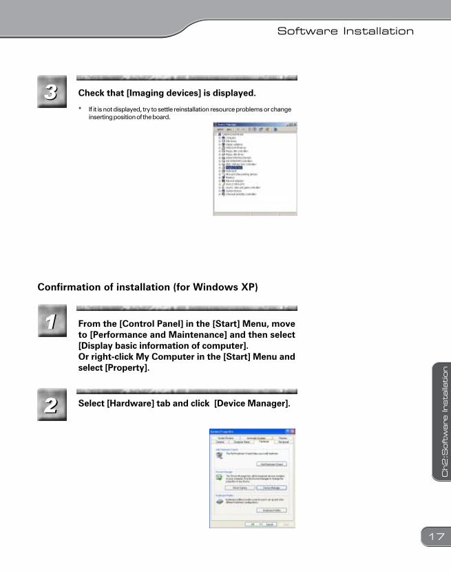
Confirmation of installation (for Windows XP)
From the [Control Panel] in the [Start] Menu, moveto [Performance and Maintenance] and then select[Display basic information of computer].Or right-click My Computer in the [Start] Menu andselect [Property].
33 Check that [Imaging devices] is displayed.
* If it is not displayed, try to settle reinstallation resource problems or changeinserting position of the board.
11
Select [Hardware] tab and click [Device Manager].
ACEDVio0516.p65 2003/05/16, 21:4717
Software Installation
18
Ch2:S
oftw
are
Insta
llatio
n
33
44
> Check that [NEC OHCI Compliant IEEE 1394 HostController] is displayed.
> If “!” or “x” is marked in front of [NEC OHCI CompliantIEEE 1394 Host Controller],theACEDVio has not been installed properly.
* Try to settle reinstallation resource problems or change inserting postionof the board.
* The configuration of the Device Manager differs depending upon yourenvironment.
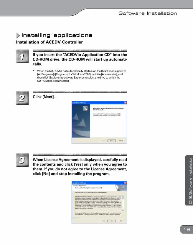
Check that [Imaging devices] and [Network adapt-ers] > [1394 Network Adapter] are displayed.
* If it is not displayed, try to settle reinstallation resource problems or changeinserting position of the board.
Double-click [IEEE 1394 Bus host controllers].
ACEDVio0516.p65 2003/05/16, 21:4718
Software Installation
19
Ch2:S
oftw
are
Insta
llation
Installing applicationsInstalling applicationsInstalling applicationsInstalling applicationsInstalling applications
11
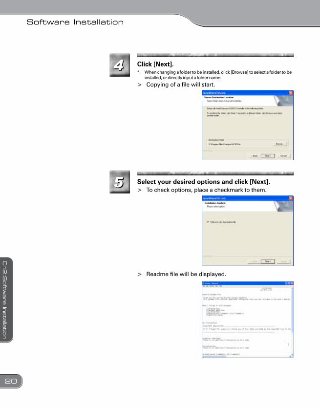
Click [Next].
Installation of ACEDV Controller
* When the CD-ROM is not automatically started, on the [Start] menu, point to[All Programs] ([Programs] for Windows 2000), point to [Accessories], andthen click [Explorer] to activate Explorer to select the drive to which theCD-ROM has been inserted.
If you insert the “ACEDVio Application CD” into theCD-ROM drive, the CD-ROM will start up automati-cally.
33 When License Agreement is displayed, carefully readthe contents and click [Yes] only when you agree tothem. If you do not agree to the License Agreement,click [No] and stop installing the program.
22
ACEDVio0516.p65 2003/05/16, 21:4719
Software Installation
20
Ch2:S
oftw
are
Insta
llatio
n
44* When changing a folder to be installed, click [Browse] to select a folder to be
installed, or directly input a folder name.
> Copying of a file will start.
Click [Next].
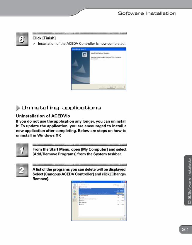
55 Select your desired options and click [Next].
> Readme file will be displayed.
> To check options, place a checkmark to them.
ACEDVio0516.p65 2003/05/16, 21:4820
Software Installation
21
Ch2:S
oftw
are
Insta
llation
A list of the programs you can delete will be displayed.Select [Canopus ACEDV Controller] and click [Change/Remove].
Uninstalling applicationsUninstalling applicationsUninstalling applicationsUninstalling applicationsUninstalling applications
Uninstallation of ACEDVio
From the Start Menu, open [My Computer] and select[Add/Remove Programs] from the System taskbar.
If you do not use the application any longer, you can uninstallit. To update the application, you are encouraged to install anew application after completing. Below are steps on how touninstall in Windows XP.
66 Click [Finish]> Installation of the ACEDV Controller is now completed.
22
11
ACEDVio0516.p65 2003/05/16, 21:4821
Software Installation
22
Ch2:S
oftw
are
Insta
llatio
n
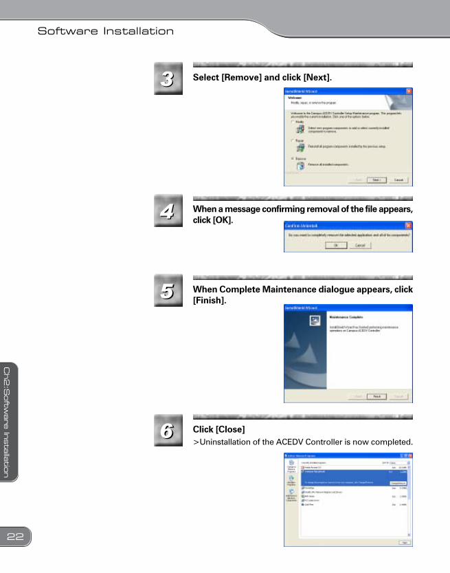
33 Select [Remove] and click [Next].
When a message confirming removal of the file appears,click [OK].
66
When Complete Maintenance dialogue appears, click[Finish].
Click [Close]>Uninstallation of the ACEDV Controller is now completed.
44
555
ACEDVio0516.p65 2003/05/16, 21:4822
Chapter 3Chapter 3Chapter 3Chapter 3Chapter 3OperationsOperationsOperationsOperationsOperations
ACEDVio0516.p65 2003/05/16, 21:4823
Operations
24
Ch3
: Operatio
ns
Starting the ApplicationStarting the ApplicationStarting the ApplicationStarting the ApplicationStarting the Application
11
22
Starting up the ACEDV ControllerStarting up the ACEDV ControllerStarting up the ACEDV ControllerStarting up the ACEDV ControllerStarting up the ACEDV Controller
* Under Windows 2000 environment, [Programs] will be displayed instead of[All Programs].
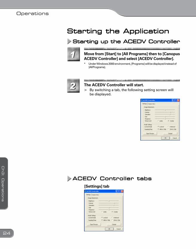
Move from [Start] to [All Programs] then to [CanopusACEDV Controller] and select [ACEDV Controller].
The ACEDV Controller will start.> By switching a tab, the following setting screen will
be displayed.
ACEDV Controller tabsACEDV Controller tabsACEDV Controller tabsACEDV Controller tabsACEDV Controller tabs
[Settings] tab
ACEDVio0516.p65 2003/05/16, 21:4824
Operations
25
Ch3
: O
peratio
ns
Displays the preview screen.
Image AdjustmentsAllows you to adjust the brightness, contrast, saturation, hue, sharpness,and setup level of images input via the line-in terminal.
Audio SettingsAllows you to set up the audio-related settings for capturing. You canconfigure the settings such as ON/OFF of Locked Audio and selectionof Sampling Rate here.
Sampling Rate
This product employs the Locked Audio technology, which digitizessound in strict accordance with video speed. No sound delay will occurin analog input by synchronizing video image and sound data.
48kHz 16-bit modeRecords audio data in 48kHz 16-bit stereo sound format.32kHz 12-bit modeThis mode records data in a format having 4 channels of 32kHz 12-bitdata. When data is recorded using ACEDVio, only the main 2 channelsare used for recording and the other two will contain no sound.
[Open Preview]
Restores the default value.
Locked Audio
[Default]
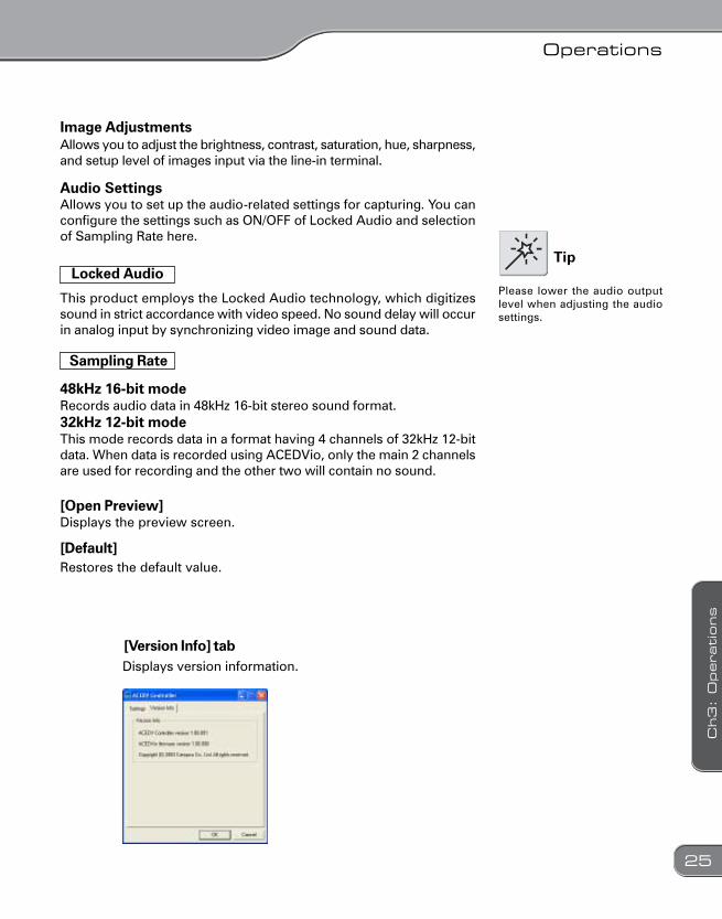
[Version Info] tabDisplays version information.
Please lower the audio outputlevel when adjusting the audiosettings.
Tip
ACEDVio0516.p65 2003/05/16, 21:4825
Operations
26
Ch3
: Operatio
ns
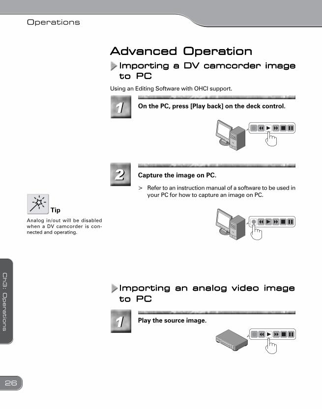
Advanced OperationAdvanced OperationAdvanced OperationAdvanced OperationAdvanced OperationImporting a DV camcorder imageImporting a DV camcorder imageImporting a DV camcorder imageImporting a DV camcorder imageImporting a DV camcorder imageto PCto PCto PCto PCto PC
On the PC, press [Play back] on the deck control.
Capture the image on PC.
> Refer to an instruction manual of a software to be used inyour PC for how to capture an image on PC.
11
22
Using an Editing Software with OHCI support.
ImImImImImporting an analog video imageporting an analog video imageporting an analog video imageporting an analog video imageporting an analog video imageto PCto PCto PCto PCto PC
Play the source image.11
Analog in/out will be disabledwhen a DV camcorder is con-nected and operating.
Tip
ACEDVio0516.p65 2003/05/16, 21:4826
Operations
27
Ch3
: O
peratio
ns
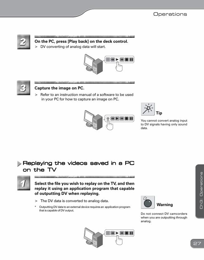
On the PC, press [Play back] on the deck control.> DV converting of analog data will start.
> Refer to an instruction manual of a software to be used in your PC for how to capture an image on PC.
Capture the image on PC.
Replaying the videos saved in a PCReplaying the videos saved in a PCReplaying the videos saved in a PCReplaying the videos saved in a PCReplaying the videos saved in a PCon the TVon the TVon the TVon the TVon the TV
* Outputting DV data to an external device requires an application programthat is capable of DV output.
> The DV data is converted to analog data.
Select the file you wish to replay on the TV, and thenreplay it using an application program that capableof outputting DV when replaying.
22
33
11
Tip
You cannot convert analog inputto DV signals having only sounddata.
Warning
Do not connect DV camcorderswhen you are outputting throughanalog.
ACEDVio0516.p65 2003/05/16, 21:4827
Specifications
28
Specific
atio
ns
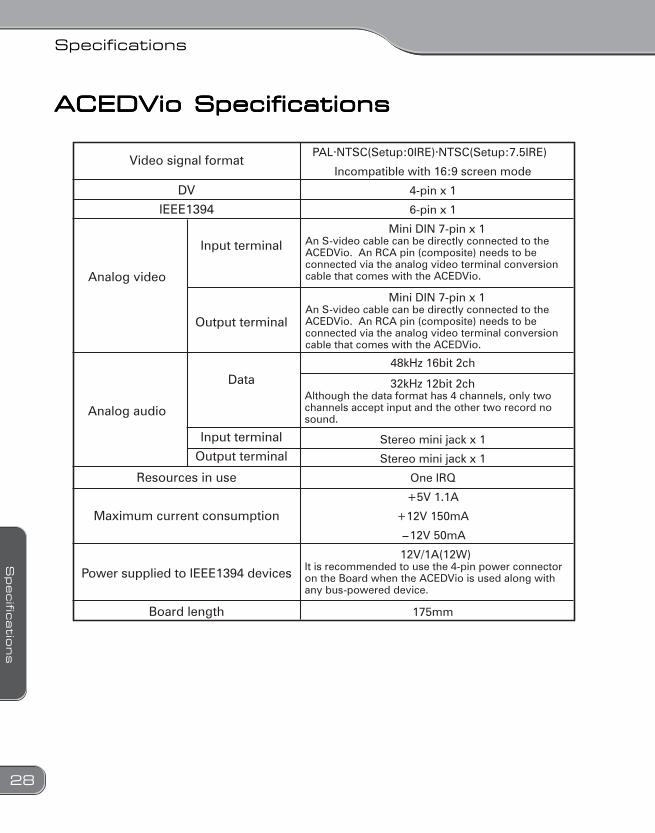
Input terminal
Output terminal
Data
Input terminal
Output terminal
Analog video
Analog audio
Video signal format
Resources in use
Maximum current consumption
Power supplied to IEEE1394 devices
Board length
PAL NTSC(Setup:0IRE) NTSC(Setup:7.5IRE)
Incompatible with 16:9 screen mode
4-pin x 1
6-pin x 1
Stereo mini jack x 1
Stereo mini jack x 1
One IRQ
+5V 1.1A
+12V 150mA
12V 50mA
175mm
48kHz 16bit 2ch
Mini DIN 7-pin x 1An S-video cable can be directly connected to the ACEDVio. An RCA pin (composite) needs to be connected via the analog video terminal conversion cable that comes with the ACEDVio.
Mini DIN 7-pin x 1An S-video cable can be directly connected to the ACEDVio. An RCA pin (composite) needs to be connected via the analog video terminal conversion cable that comes with the ACEDVio.
32kHz 12bit 2chAlthough the data format has 4 channels, only two channels accept input and the other two record no sound.
12V/1A(12W)It is recommended to use the 4-pin power connector on the Board when the ACEDVio is used along with any bus-powered device.
DV
IEEE1394
ACEDVio SpecificationsACEDVio SpecificationsACEDVio SpecificationsACEDVio SpecificationsACEDVio Specifications
ACEDVio0516.p65 2003/05/16, 21:4928