Embed Size (px)
Citation preview
1/26 AIChE Chicago Nov. 12th
Sage Kokjohn
Acknowledgments
Direct-injection Engine Research Consortium (DERC)
US Department of Energy/Sandia National Labs
Rolf D. Reitz and Mark P.B. Musculus
Achieving High Efficiency Combustion by
Controlling Fuel Reactivity
AIChE Chicago Nov. 12th
2/26 AIChE Chicago Nov. 12th
Outline
• Motivation for investigating internal combustion (IC)
engine efficiency
• ICE background
• Requirements for high-efficiency combustion
• A pathway to high-efficiency clean combustion using in-
cylinder blending of fuels with different auto-ignition
characteristics
– Conventional fuels
– Details of combustion process
– Alternative fuels
• Conclusions

3/26 AIChE Chicago Nov. 12th
Why research IC engine efficiency?
• Internal combustion engines are used in a variety of applications
from transportation to power generation
• 70% of all crude oil consumed is used to fuel internal
combustion engines
• United States spends more than 3% of GDP on oil to fuel IC engines
• IC engines are expected to be the dominant (>90%) prime
mover for transportation applications well into the future1,2,3
• Improvements in the efficiency of IC engines can have a major
impact on fossil fuel consumption and green house gas (GHG)
emissions on a global scale
– A 1% improvement in efficiency equates to a fuel savings of ~$4 billion per
year
1Quadrennial Technology Review, DOE 20112Review of the Research Program of the FreedomCAR and Fuel
Partnership: 3rd Report, NRC 2010 3Energy Information Agency, Annual Energy Outlook 2012, June 2012.
4/26 AIChE Chicago Nov. 12th
Engine Combustion Background
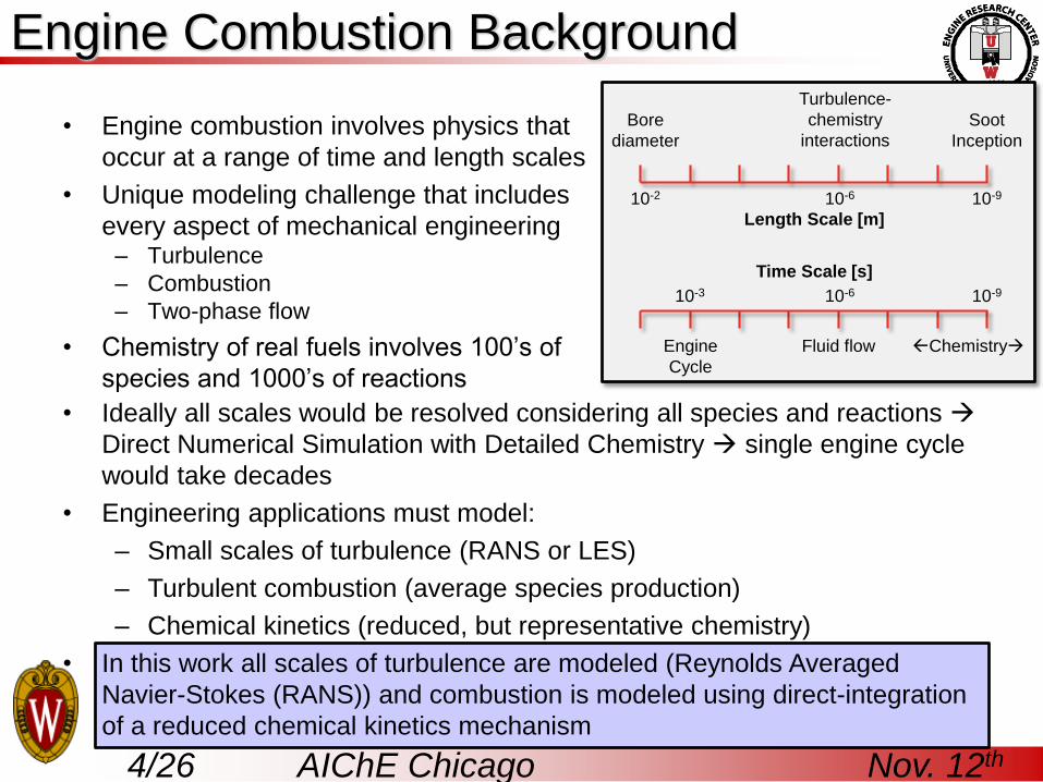
• Engine combustion involves physics that
occur at a range of time and length scales
• Unique modeling challenge that includes
every aspect of mechanical engineering– Turbulence
– Combustion
– Two-phase flow
• Chemistry of real fuels involves 100’s of
species and 1000’s of reactions
Bore
diameter
Turbulence-
chemistry
interactions
10-2 10-6 10-9
Soot
Inception
10-3 10-6 10-9
Engine
Cycle
Fluid flow Chemistry
Length Scale [m]
Time Scale [s]
• Ideally all scales would be resolved considering all species and reactions
Direct Numerical Simulation with Detailed Chemistry single engine cycle
would take decades
• Engineering applications must model:
– Small scales of turbulence (RANS or LES)
– Turbulent combustion (average species production)
– Chemical kinetics (reduced, but representative chemistry)
• In this work all scales of turbulence are modeled (Reynolds Averaged
Navier-Stokes (RANS)) and combustion is modeled using direct-integration
of a reduced chemical kinetics mechanism
5/26 AIChE Chicago Nov. 12th
Internal Combustion Engine Terminology
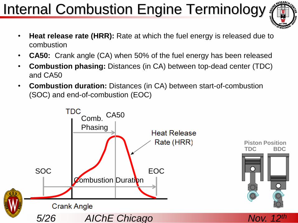
• Heat release rate (HRR): Rate at which the fuel energy is released due to
combustion
• CA50: Crank angle (CA) when 50% of the fuel energy has been released
• Combustion phasing: Distances (in CA) between top-dead center (TDC)
and CA50
• Combustion duration: Distances (in CA) between start-of-combustion
(SOC) and end-of-combustion (EOC)
CA50Comb.
Phasing
Combustion Duration
SOC EOC
Piston PositionBDCTDC
6/26 AIChE Chicago Nov. 12th
Internal Combustion Engine Terminology
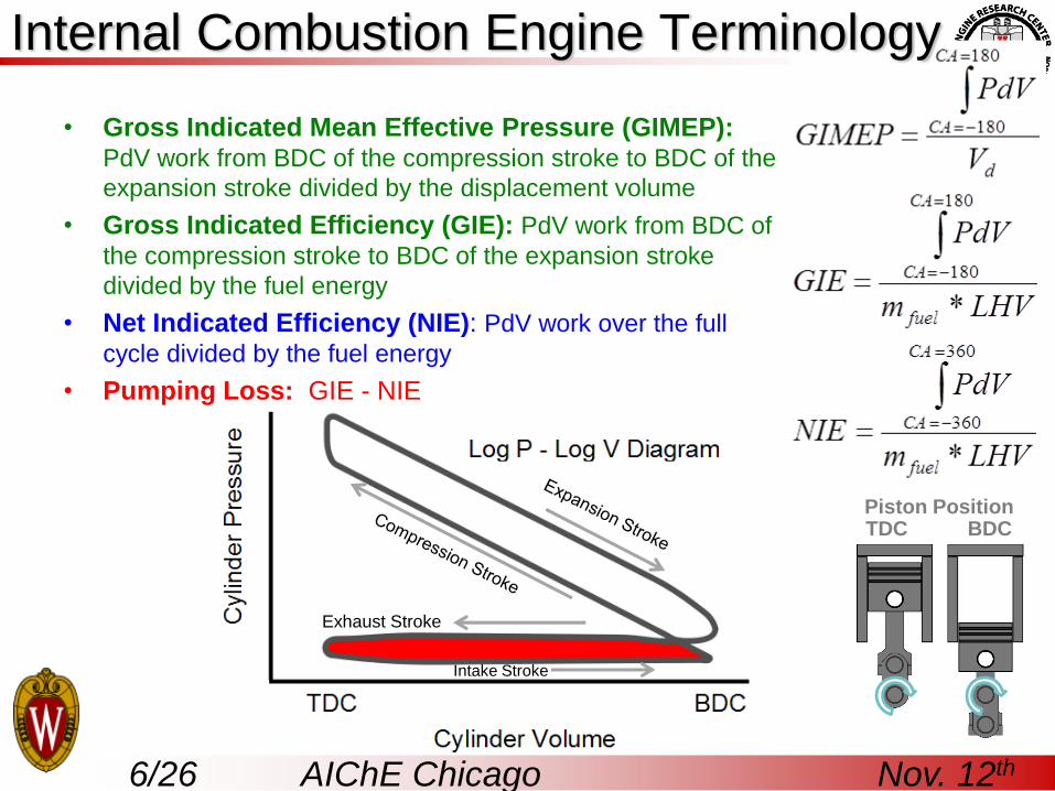
• Gross Indicated Mean Effective Pressure (GIMEP):PdV work from BDC of the compression stroke to BDC of the
expansion stroke divided by the displacement volume
• Gross Indicated Efficiency (GIE): PdV work from BDC of
the compression stroke to BDC of the expansion stroke
divided by the fuel energy
• Net Indicated Efficiency (NIE): PdV work over the full
cycle divided by the fuel energy
• Pumping Loss: GIE - NIE
Piston PositionBDCTDC
Exhaust Stroke
Intake Stroke
7/26 AIChE Chicago Nov. 12th
Maximizing Engine Efficiency
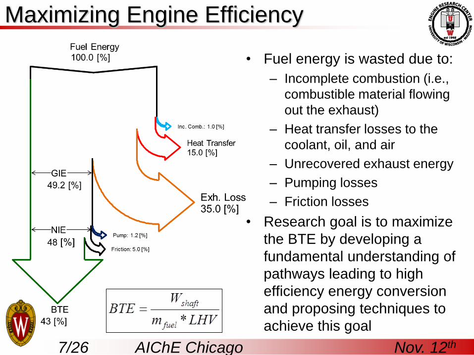
• Fuel energy is wasted due to:
– Incomplete combustion (i.e.,
combustible material flowing
out the exhaust)
– Heat transfer losses to the
coolant, oil, and air
– Unrecovered exhaust energy
– Pumping losses
– Friction losses
• Research goal is to maximize
the BTE by developing a
fundamental understanding of
pathways leading to high
efficiency energy conversion
and proposing techniques to
achieve this goal

8/26 AIChE Chicago Nov. 12th
Maximizing Engine Efficiency
• Maximize combustion efficiency
– In-cylinder temperatures must exceed ~1500 K to convert CO to CO2
• Minimize fuel (or fluid) consumption penalties of aftertreatment avoid
forming NOx and soot emissions
– Peak combustion temperatures must be below ~2000 K to avoid forming NOx
– Fuel and air must be sufficiently mixed to avoid soot
• Minimize heat transfer losses
– Keep combustion temperatures low and
avoid high levels of charge motion
(minimize convection losses)
• Maximize expansion work (i.e.,
operate with a high expansion ratio)
– Begin with high geometric
compression ratio
– Combustion phasing must be well
controlled and near TDC
– Combustion duration must be short,
but controlled
High Efficiency
Clean Regime
Stoichiometric
Fuel Rich
Fuel Lean
Equivalence ratio (ϕ): the
stoichiometric air-fuel-ratio (AFR)
divided by the actual air-fuel-ratio
9/26 AIChE Chicago Nov. 12th
Conventional Combustion Modes
SI Combustion
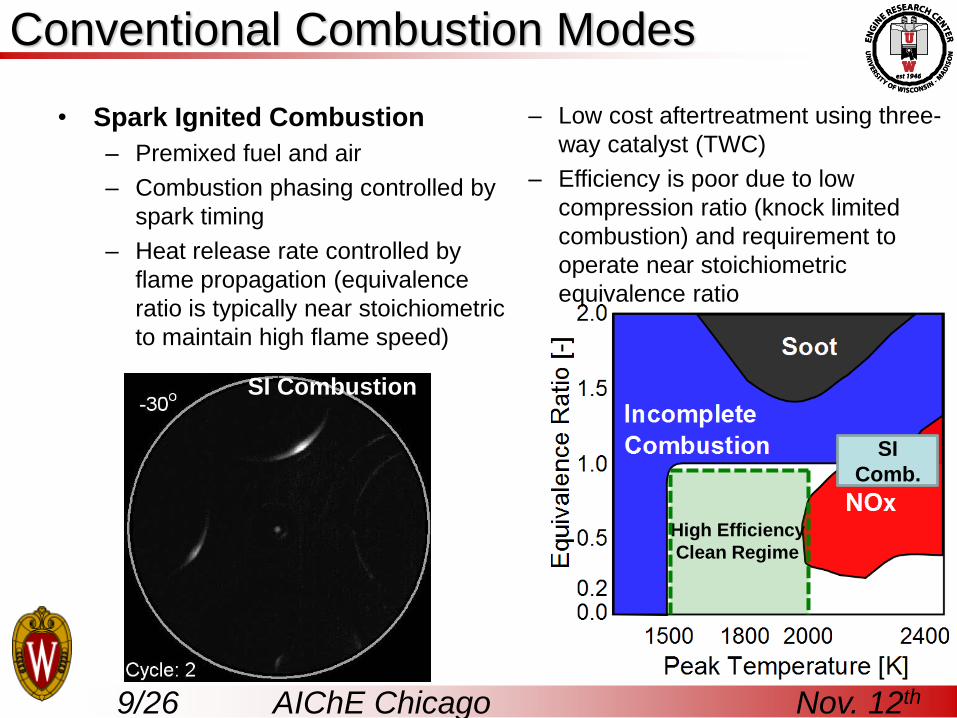
• Spark Ignited Combustion
– Premixed fuel and air
– Combustion phasing controlled by
spark timing
– Heat release rate controlled by
flame propagation (equivalence
ratio is typically near stoichiometric
to maintain high flame speed)
– Low cost aftertreatment using three-
way catalyst (TWC)
– Efficiency is poor due to low
compression ratio (knock limited
combustion) and requirement to
operate near stoichiometric
equivalence ratio
SI
Comb.
High Efficiency
Clean Regime

10/26 AIChE Chicago Nov. 12th
Conventional Combustion Modes
• Diesel Combustion
– Fuel and air are mixed during the
combustion process
– Mixing controlled combustion
results in soot and NOx formation
– High compression ratio and lean
operation results in higher efficiency
than spark ignited combustion
– Lean operation does not allow the
use of a three-way catalyst NOx
aftertreatment is costly and
increases fuel (fluid) consumption
– High temperature regions increase
heat transfer losses
High Efficiency
Clean Regime
Diesel (Compression
Ignition) Combustion
11/26 AIChE Chicago Nov. 12th
• Fuel and air are well
mixed (like SI comb.)
• Overall lean charge and
compression ignition
(like diesel comb.)
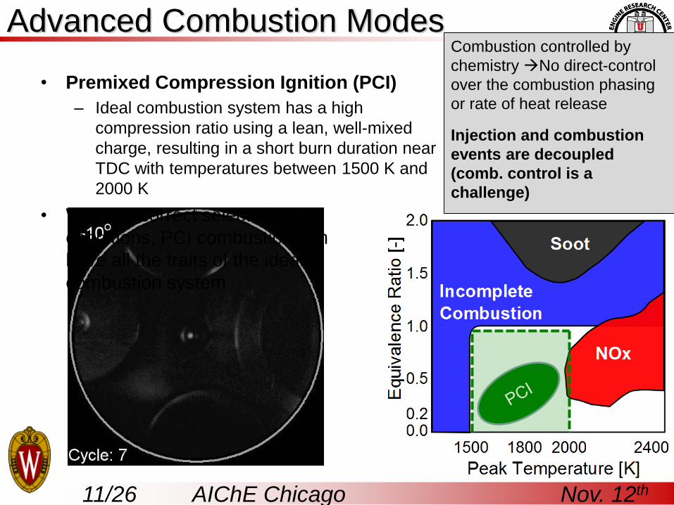
Advanced Combustion Modes
• Premixed Compression Ignition (PCI)
– Ideal combustion system has a high
compression ratio using a lean, well-mixed
charge, resulting in a short burn duration near
TDC with temperatures between 1500 K and
2000 K
• With the correct selection of
conditions, PCI combustion can
have all the traits of the ideal
combustion system
Combustion controlled by
chemistry No direct-control
over the combustion phasing
or rate of heat release
Injection and combustion
events are decoupled
(comb. control is a
challenge)
12/26 AIChE Chicago Nov. 12th
Advanced Combustion Modes
• Highly-premixed compression ignition (PCI) strategies offer attractive
emissions and performance characteristics; however, in practice PCI
strategies are generally confined to low-load operation due to
– lack of adequate combustion phasing control
– difficulties controlling the rate-of-heat release (combustion noise)
• Common fuels (e.g., gasoline and diesel fuel) have different auto-
ignition characteristics
– Diesel fuel is easy to ignite (high reactivity) – good for low load/low temp.
– Gasoline is difficult to ignite (low reactivity) – good for high load/high temp
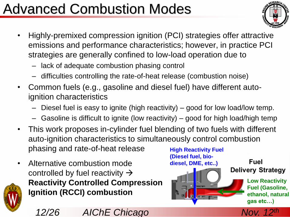
• This work proposes in-cylinder fuel blending of two fuels with different
auto-ignition characteristics to simultaneously control combustion
phasing and rate-of-heat release
• Alternative combustion mode
controlled by fuel reactivity
Reactivity Controlled Compression
Ignition (RCCI) combustion
High Reactivity Fuel
(Diesel fuel, bio-
diesel, DME, etc..)
Low Reactivity
Fuel (Gasoline,
ethanol, natural
gas etc…)
13/26 AIChE Chicago Nov. 12th
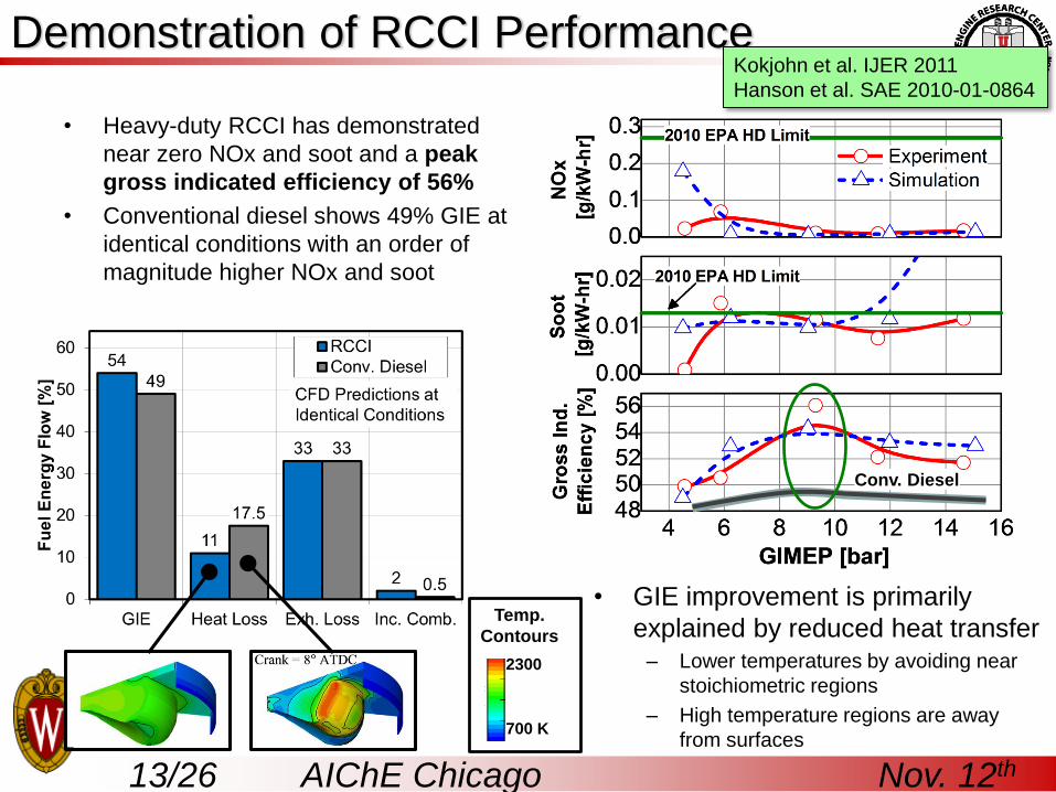
Demonstration of RCCI Performance
• Heavy-duty RCCI has demonstrated
near zero NOx and soot and a peak
gross indicated efficiency of 56%
• Conventional diesel shows 49% GIE at
identical conditions with an order of
magnitude higher NOx and soot
Conv. Diesel
2300
700 K
Temp.
Contours
Kokjohn et al. IJER 2011
Hanson et al. SAE 2010-01-0864
• GIE improvement is primarily
explained by reduced heat transfer – Lower temperatures by avoiding near
stoichiometric regions
– High temperature regions are away
from surfaces
14/26 AIChE Chicago Nov. 12th
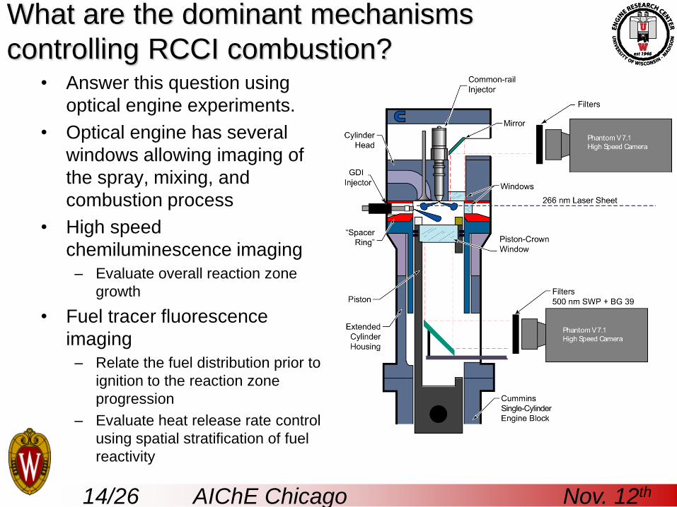
What are the dominant mechanisms
controlling RCCI combustion?• Answer this question using
optical engine experiments.
• Optical engine has several
windows allowing imaging of
the spray, mixing, and
combustion process
• High speed
chemiluminescence imaging
– Evaluate overall reaction zone
growth
• Fuel tracer fluorescence
imaging
– Relate the fuel distribution prior to
ignition to the reaction zone
progression
– Evaluate heat release rate control
using spatial stratification of fuel
reactivity
15/26 AIChE Chicago Nov. 12th
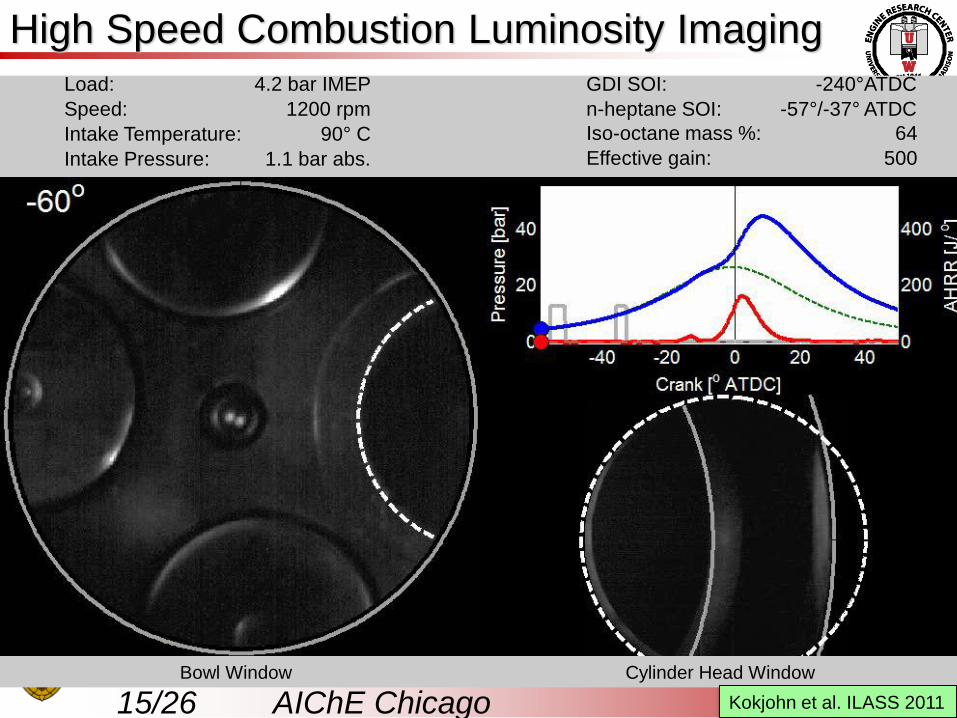
High Speed Combustion Luminosity Imaging
Bowl Window Cylinder Head Window
Load: 4.2 bar IMEP GDI SOI: -240°ATDC
Speed: 1200 rpm n-heptane SOI: -57°/-37° ATDC
Intake Temperature: 90° C Iso-octane mass %: 64
Intake Pressure: 1.1 bar abs. Effective gain: 500
Kokjohn et al. ILASS 2011
16/26 AIChE Chicago Nov. 12th
7060504030
10
0
-10
45
50
50
55
55
55
60
60
657075
Distance from Injector [mm]
Dis
tance f
rom
Inje
cto
r [m
m]
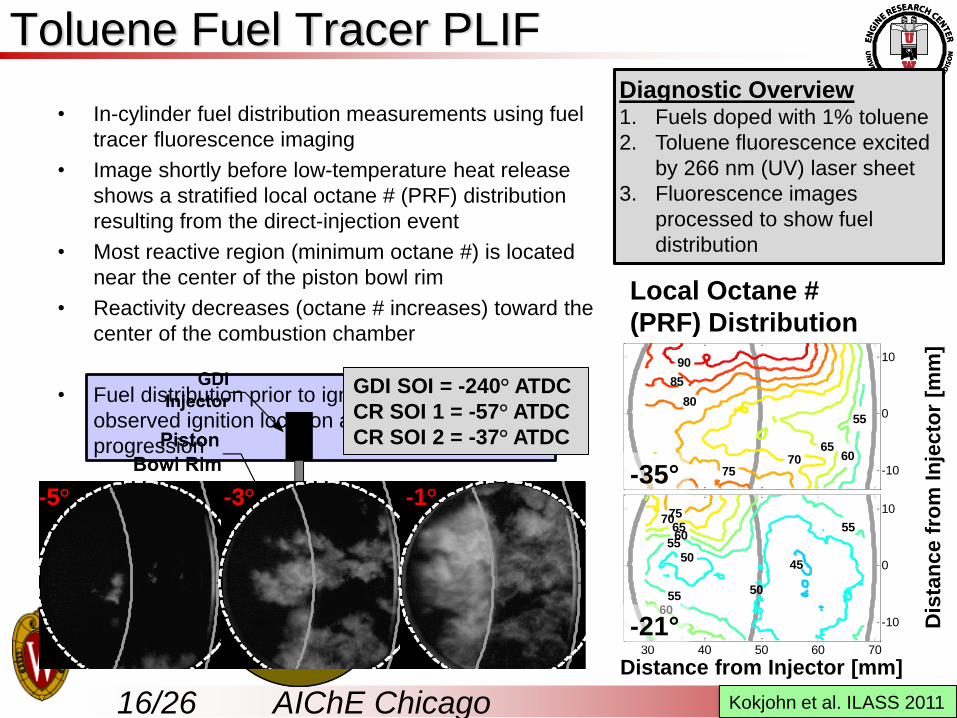
Toluene Fuel Tracer PLIF
• In-cylinder fuel distribution measurements using fuel
tracer fluorescence imaging
• Image shortly before low-temperature heat release
shows a stratified local octane # (PRF) distribution
resulting from the direct-injection event
• Most reactive region (minimum octane #) is located
near the center of the piston bowl rim
• Reactivity decreases (octane # increases) toward the
center of the combustion chamber
• Fuel distribution prior to ignition correlates with
observed ignition location and reaction zone
progression
7060504030
10
0
-10
55
6065
7075
80
85
90
Distance from Injector [mm]
Dis
tance f
rom
Inje
cto
r [m
m]
Distance from Injector [mm]
Dis
tan
ce f
rom
In
jecto
r [m
m]
-35°
-21°
-40 -20 0 20 400
10
20
30
40
Crank [o ATDC]
Pre
ssu
re [b
ar]
0
100
200
300
400
AH
RR
[J/
o]
-5o
-40 -20 0 20 400
10
20
30
40
Crank [o ATDC]
Pre
ssu
re [b
ar]
0
100
200
300
400
AH
RR
[J/
o]
-3o
-40 -20 0 20 400
10
20
30
40
Crank [o ATDC]
Pre
ssu
re [b
ar]
0
100
200
300
400
AH
RR
[J/
o]
-1o
-5° -3° -1°
Local Octane #
(PRF) Distribution
GDI SOI = -240° ATDC
CR SOI 1 = -57° ATDC
CR SOI 2 = -37° ATDC
Kokjohn et al. ILASS 2011
Diagnostic Overview1. Fuels doped with 1% toluene
2. Toluene fluorescence excited
by 266 nm (UV) laser sheet
3. Fluorescence images
processed to show fuel
distribution
17/26 AIChE Chicago Nov. 12th
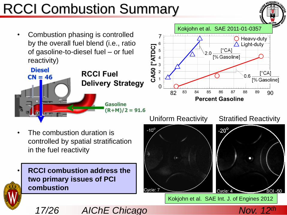
RCCI Combustion Summary
• Combustion phasing is controlled
by the overall fuel blend (i.e., ratio
of gasoline-to-diesel fuel – or fuel
reactivity)
•
• The combustion duration is
controlled by spatial stratification
in the fuel reactivity
• RCCI combustion address the
two primary issues of PCI
combustion
Uniform Reactivity Stratified Reactivity
Kokjohn et al. SAE 2011-01-0357
Kokjohn et al. SAE Int. J. of Engines 2012
18/26 AIChE Chicago Nov. 12th
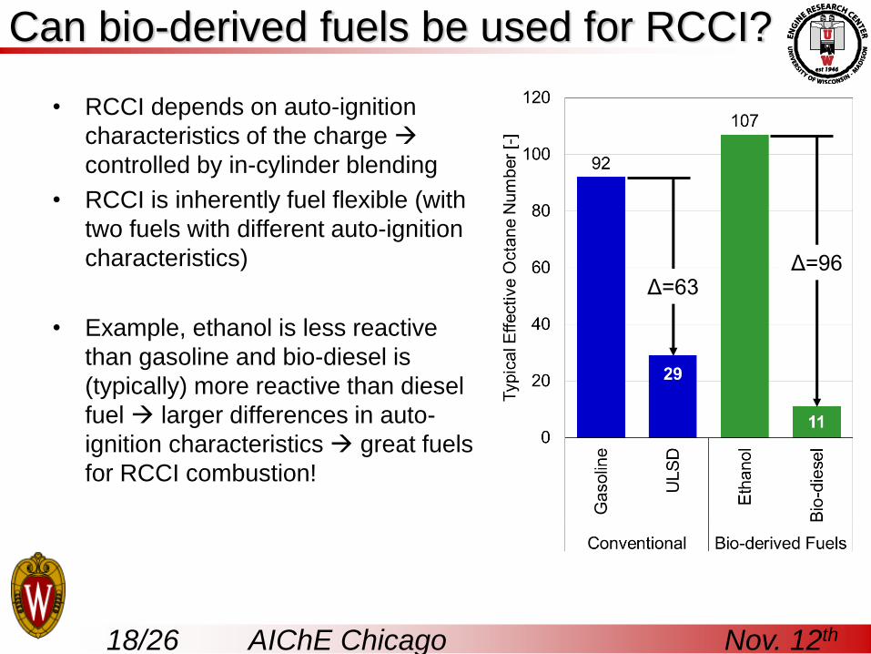
Can bio-derived fuels be used for RCCI?
• RCCI depends on auto-ignition
characteristics of the charge
controlled by in-cylinder blending
• RCCI is inherently fuel flexible (with
two fuels with different auto-ignition
characteristics)
• Example, ethanol is less reactive
than gasoline and bio-diesel is
(typically) more reactive than diesel
fuel larger differences in auto-
ignition characteristics great fuels
for RCCI combustion!
Δ=63Δ=96

19/26 AIChE Chicago Nov. 12th
Can bio-derived fuels be used for RCCI?
• Gasoline-diesel RCCI is compared to E85-diesel RCCI combustion
• E85-diesel DF RCCI exhibits significantly reduced HRR compared to gasoline-diesel RCCI quieter operation and extended load range
• Both show near zero levels of NOx and GIE significantly above state of the art diesel engines (diesel GIE ~49% at peak)
0
2
4
6
8
10
12E85 and
Diesel Fuel
E85 & Diesel - Experiment
Gasoline & Diesel - ExperimentPre
ssu
re [
MP
a]
Gasoline
and Diesel Fuel
-20 -15 -10 -5 0 5 10 15 200
100
200
300
400
500
600
700
Crank [ATDC]
AH
RR
[J/d
eg
]
Splitter et al., SAE 2011-01-0363
20/26 AIChE Chicago Nov. 12th
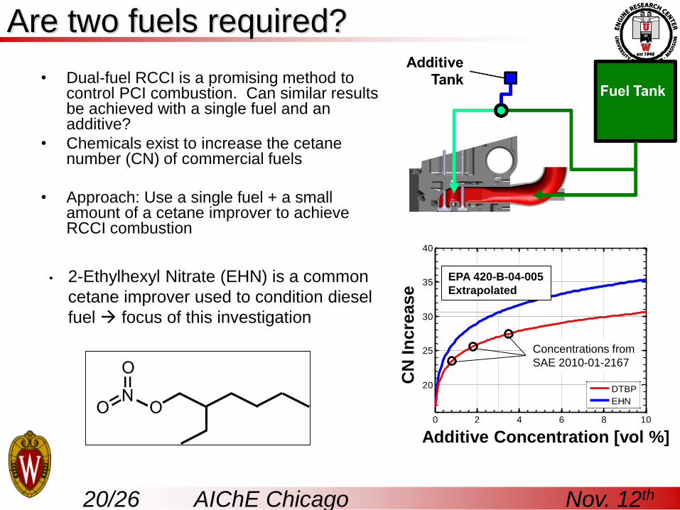
• 2-Ethylhexyl Nitrate (EHN) is a common
cetane improver used to condition diesel
fuel focus of this investigation
Are two fuels required?
• Dual-fuel RCCI is a promising method to control PCI combustion. Can similar results be achieved with a single fuel and an additive?
• Chemicals exist to increase the cetanenumber (CN) of commercial fuels
• Approach: Use a single fuel + a small amount of a cetane improver to achieve RCCI combustion
0 2 4 6 8 10
20
25
30
35
40
Additive Concentration [Vol %]
Estim
ate
d C
N
DTBP
EHN
EPA 420-B-04-005
Extrapolated
CN
Incre
ase
Additive Concentration [vol %]
Concentrations from
SAE 2010-01-2167
21/26 AIChE Chicago Nov. 12th
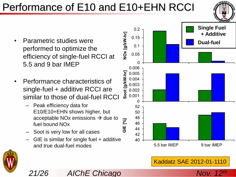
Performance of E10 and E10+EHN RCCI
• Parametric studies were
performed to optimize the
efficiency of single-fuel RCCI at
5.5 and 9 bar IMEP
• Performance characteristics of
single-fuel + additive RCCI are
similar to those of dual-fuel RCCI
– Peak efficiency data for
E10/E10+EHN shows higher, but
acceptable NOx emissions due to
fuel bound NOx
– Soot is very low for all cases
– GIE is similar for single fuel + additive
and true dual-fuel modes
E10/E10+EHN
E10/Diesel
Kaddatz SAE 2012-01-1110
Single Fuel
+ Additive
Dual-fuel
22/26 AIChE Chicago Nov. 12th
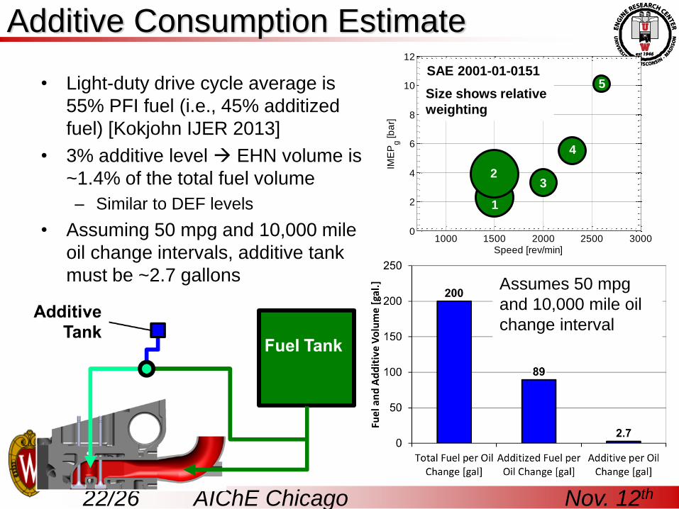
Additive Consumption Estimate
• Light-duty drive cycle average is
55% PFI fuel (i.e., 45% additized
fuel) [Kokjohn IJER 2013]
• 3% additive level EHN volume is
~1.4% of the total fuel volume
– Similar to DEF levels
• Assuming 50 mpg and 10,000 mile
oil change intervals, additive tank
must be ~2.7 gallons
1000 1500 2000 2500 30000
2
4
6
8
10
12
Speed [rev/min]
IME
Pg [b
ar]
4
32
5
1
SAE 2001-01-0151
Size shows relative
weighting
Assumes 50 mpg
and 10,000 mile oil
change interval
23/26 AIChE Chicago Nov. 12th
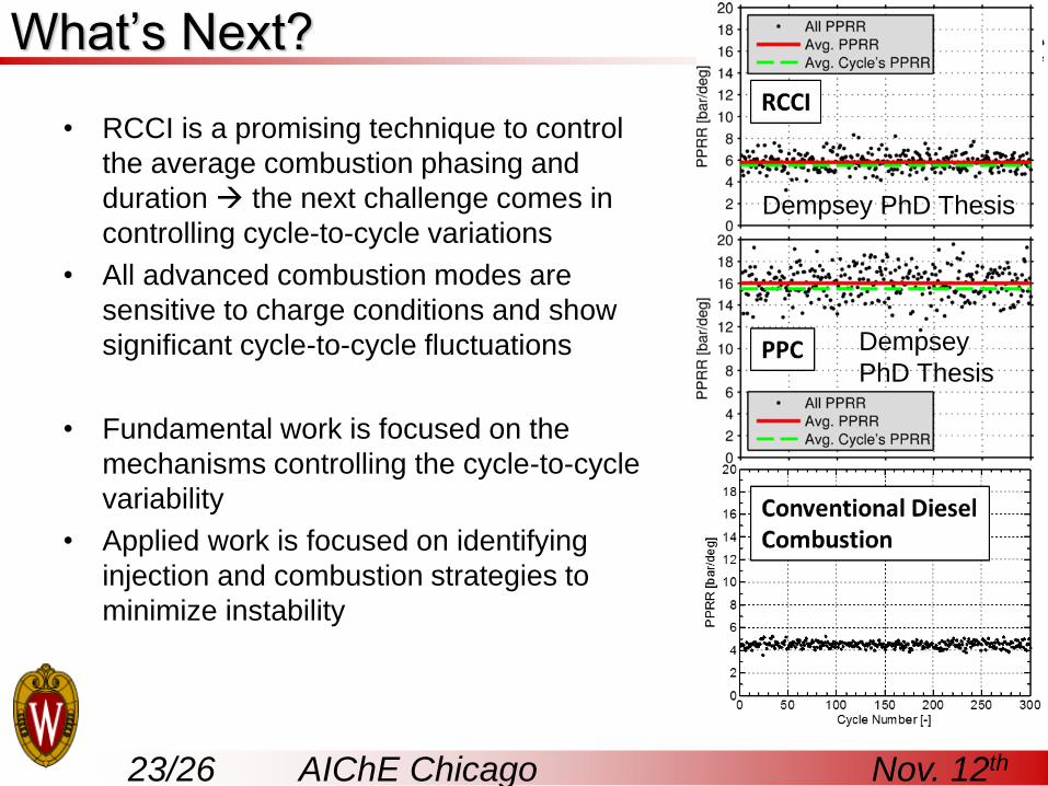
What’s Next?
• RCCI is a promising technique to control
the average combustion phasing and
duration the next challenge comes in
controlling cycle-to-cycle variations
• All advanced combustion modes are
sensitive to charge conditions and show
significant cycle-to-cycle fluctuations
• Fundamental work is focused on the
mechanisms controlling the cycle-to-cycle
variability
• Applied work is focused on identifying
injection and combustion strategies to
minimize instability
Dempsey PhD Thesis
Dempsey
PhD Thesis
24/26 AIChE Chicago Nov. 12th
What’s Next?
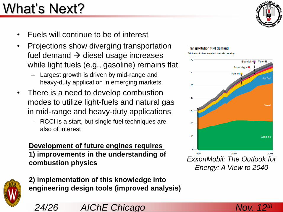
• Fuels will continue to be of interest
• Projections show diverging transportation
fuel demand diesel usage increases
while light fuels (e.g., gasoline) remains flat
– Largest growth is driven by mid-range and
heavy-duty application in emerging markets
• There is a need to develop combustion
modes to utilize light-fuels and natural gas
in mid-range and heavy-duty applications
– RCCI is a start, but single fuel techniques are
also of interest
ExxonMobil: The Outlook for
Energy: A View to 2040
Development of future engines requires
1) improvements in the understanding of
combustion physics
2) implementation of this knowledge into
engineering design tools (improved analysis)
25/26 AIChE Chicago Nov. 12th
Conclusions
• A dual-fuel PCI concept is proposed using in-cylinder blending of
two fuels with different auto-ignition characteristics
• Controlled PCI operation demonstrated with very high efficiency and
near zero NOx and soot emissions over a range of loads
• New combustion concept addresses the two primary issues limiting
acceptance of PCI combustion
– Combustion phasing is easily controlled by adjusting the overall fuel
reactivity (e.g., gasoline-to-diesel ratio)
– Combustion duration is controlled by introducing spatial stratification
into the auto-ignition characteristics of the charge
• RCCI combustion is inherently fuel flexible and well-suited for use
with bio-derived fuels engine adapts to fuel ignition characteristics
on-the-fly to maintain peak efficiency
• Single-fuel + additive operation can achieve similar performance to
a dual-fuel strategy with an additive tank that needs to be filled at oil
change intervals.
26/26 AIChE Chicago Nov. 12th
Contact Info
Sage Kokjohn
(608) 263-1610
More Information
• “Engine Combustion Control via
Fuel Reactivity Stratification" -
P100054US01, Nov. 2013
• Kokjohn et al. IJER 2011
• Kokjohn et al. IJER 2013
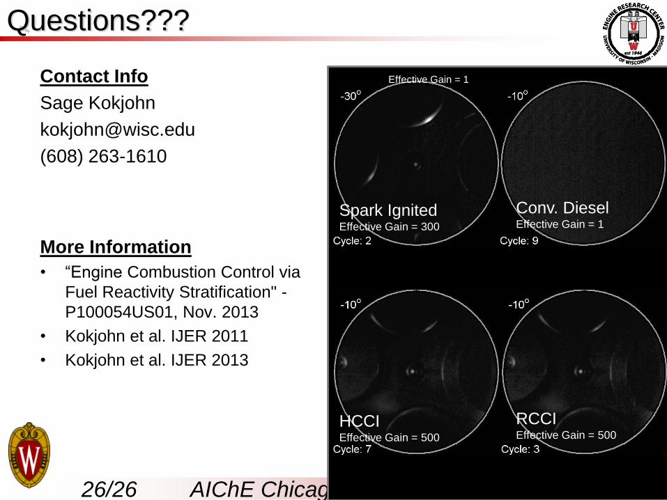
Spark IgnitedEffective Gain = 300
Conv. Diesel Effective Gain = 1
HCCIEffective Gain = 500
RCCIEffective Gain = 500
Effective Gain = 1
Questions???