Embed Size (px)
Citation preview

Water Technologies & Solutions technical paper
Find a contact near you by visiting www.suezwatertechnologies.com and clicking on “Contact Us.” *Trademark of SUEZ; may be registered in one or more countries. ©2017 SUEZ. All rights reserved. TP1045EN.docx Feb-11
achieving zero liquid discharge in SAGD heavy oil recovery Authors: W. Heins and K. Schooley, Resource Conservation Company (RCC)
Note: SUEZ purchased RCC in 2005.
abstract
Designing a plant for maximum water recycle and reuse (i.e., zero liquid discharge) is not the mystery it once was. Planning to implement zero liquid discharge right from the start wins faster community acceptance, streamlines the permitting process, eliminates the need for deep well injection or other disposal methods, and minimizes make-up water requirements. Over 100 mechanical zero liquid discharge systems are now in operation worldwide using RCC* Brine Concentrator and Crystallizer technologies., including two SAGD heavy oil recovery projects currently underway in Alberta. Wastewater is converted by the Brine Concentrator to extremely pure distilled water for reuse in the steam generator or other process applications. The waste from the Brine Concentrator is reduced to dry solids in the Crystallizer, while recovering the remaining wastewater for reuse.
This paper will discuss the various applications of Brine Concentrators and Crystallizers as they apply to SAGD heavy oil recovery produced water treatment. Specific examples will be used to illustrate the wastewater recycling process and demonstrate how the zero liquid discharge system is integrated into the SAGD heavy oil recovery process.
introduction
Traditional Heavy Oil Recovery Process
Water treatment is a necessary operation in the heavy oil recovery process. In order to recover heavy oil from
certain geologic formations, steam is required to improve the mobility of the oil. Traditionally, “once-through” steam generators have been used to produce 80% quality steam (80% vapor, 20% liquid) for injection into the well to fluidize the heavy oil and allow the oil/water mixture to be pumped to the surface. The oil and water are separated. The oil is recovered as product and the water, referred to as produced water, is de-oiled and treated for reuse in the steam generator. The produced water, which must typically be <8000 ppm (mg/L) TDS, as well as meeting other specific constituent requirements, is typically pretreated using hot or warm lime softening, a weak acid cation system, and other processes prior to use in the steam generator.
The SAGD Heavy Oil Process
A relatively new heavy oil recovery process, referred to as SAGD (Steam Assisted Gravity Drainage), requires 100% quality steam to be injected into the well (i.e., no liquid water). To produce 100% quality steam using once-through steam generators, a series of vapor-liquid separators arerequired to separate the liquid water from the steam. The 100% quality steam is then injected into the well. The separated water is then either disposed of via deep-well injection or, if deep well injection is not possible, the separated water may be taken to Zero Liquid Discharge (ZLD) using a Brine Concentrator and/or a salt Crystallizer.

Page 2 TP1045EN.docx
brine concentrators and crystallizers
Prior to addressing the details of applying Brine Concentrators and Crystallizers to the SAGD process, a brief history of evaporation and a technical explanation of the Brine Concentration and Crystallization process is presented. Following these technical descriptions, specific examples of Brine Concentration and Crystallization in the SAGD industry is presented.
A Brief History of Evaporation
Several things happened in the United States in the early 1970s to spur interest in evaporators for wastewater treatment. First was the imposition of clean water regulations such as the Clean Water Act, the National Pollution Discharge Elimination System (NPDES) and the implementation of “zero liquid discharge” regulations at the local level. These regulations justified research into treating highly saturated brine wastewater, such as cooling tower blowdown, which had previously been dumped into rivers or deep well injected. This type of wastewater, saturated with calcium sulfate and silica, is difficult to evaporate because it is already at the scaling point. Researchers in the early 1970s developed a method of adding calcium sulfate “seeds” to the saturated wastewater to give the precipitating salts a place to adhere and remain in suspension (Figure 1).
Figure 1: Seeded Slurry Technology
Seeding alone is not enough to prevent scaling. Other system variables are: geometry of the equipment, temperature, pH, residence time, system volume, crystal size, crystal composition, crystal concentration, ratios and proportions of each mineral
to other minerals, trace element presence, and evaporation rate.
Vapor Compression Cycle
The amount of energy it takes to evaporate water was also a limiting factor in the early 1970s, especially with soaring energy prices after the oil embargo. Using steam as the energy source, it takes 1000 BTUs to evaporate a pound of water. Multiple effect evaporator systems increase this efficiency, but add capital cost in the form of additional evaporator bodies. Using electricity, or the vapor compression cycle, to evaporate water increases the efficiency at least 20 times, requiring only 50 BTUs or less to evaporate a pound of water. In other words, one evaporator body driven by a mechanical vapor compressor is equivalent to a 20-effect, or 20-body system driven by steam. Vapor compression evaporation is the most economical approach unless a source of waste steam, such as low pressure (LP) separator flash steam is available.
In the early 1970s, compressor suppliers adapted high-pressure, single-stage centrifugal gascompressors to operate on steam. This was another important factor in the growth of vapor compression evaporation. Properly protected from stray salts in the steam along with prudent design factors, vapor compressors have been successfully used with evaporators since the mid-1970s.
Configuration, Materials of Construction
Boiling brines corroded low-cost aluminum in the first test evaporators. Titanium was finally selected as the most versatile heat transfer material in resisting attack from a broad array of constituents in the water. Using titanium for heat transfer meant the condenser had to be a tube-and-shell design rather than flat plate, as tubes are easier to weld than plates, offer a smooth surface for brine flow, and have better resistance to pressure. (In some SAGD applications, titanium tubes are not appropriate due to the high pH of the produced water and, therefore, high grade stainless steel tubes may instead be used.) High quality stainless steel is typically used in the vapor body and sump.
Vapor Compression Evaporator
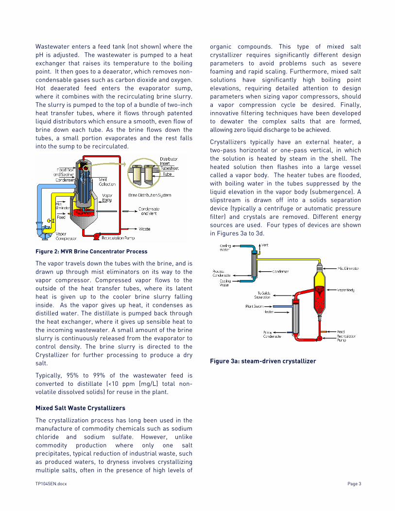
The seeded slurry vapor compression evaporator developed in the early 1970s contains all the same basic elements today. A vapor compression evaporator diagram is shown in Figure 2.
TP1045EN.docx Page 3
Wastewater enters a feed tank (not shown) where the pH is adjusted. The wastewater is pumped to a heat exchanger that raises its temperature to the boiling point. It then goes to a deaerator, which removes non-condensable gases such as carbon dioxide and oxygen. Hot deaerated feed enters the evaporator sump, where it combines with the recirculating brine slurry. The slurry is pumped to the top of a bundle of two-inch heat transfer tubes, where it flows through patented liquid distributors which ensure a smooth, even flow of brine down each tube. As the brine flows down the tubes, a small portion evaporates and the rest falls into the sump to be recirculated.
Figure 2: MVR Brine Concentrator Process
The vapor travels down the tubes with the brine, and is drawn up through mist eliminators on its way to the vapor compressor. Compressed vapor flows to the outside of the heat transfer tubes, where its latent heat is given up to the cooler brine slurry falling inside. As the vapor gives up heat, it condenses as distilled water. The distillate is pumped back through the heat exchanger, where it gives up sensible heat to the incoming wastewater. A small amount of the brine slurry is continuously released from the evaporator to control density. The brine slurry is directed to the Crystallizer for further processing to produce a dry salt.
Typically, 95% to 99% of the wastewater feed is converted to distillate (<10 ppm [mg/L] total non-volatile dissolved solids) for reuse in the plant.
Mixed Salt Waste Crystallizers
The crystallization process has long been used in the manufacture of commodity chemicals such as sodium chloride and sodium sulfate. However, unlike commodity production where only one salt precipitates, typical reduction of industrial waste, such as produced waters, to dryness involves crystallizing multiple salts, often in the presence of high levels of
organic compounds. This type of mixed salt crystallizer requires significantly different design parameters to avoid problems such as severe foaming and rapid scaling. Furthermore, mixed salt solutions have significantly high boiling point elevations, requiring detailed attention to design parameters when sizing vapor compressors, should a vapor compression cycle be desired. Finally, innovative filtering techniques have been developed to dewater the complex salts that are formed, allowing zero liquid discharge to be achieved.
Crystallizers typically have an external heater, a two-pass horizontal or one-pass vertical, in which the solution is heated by steam in the shell. The heated solution then flashes into a large vessel called a vapor body. The heater tubes are flooded, with boiling water in the tubes suppressed by the liquid elevation in the vapor body (submergence). A slipstream is drawn off into a solids separation device (typically a centrifuge or automatic pressure filter) and crystals are removed. Different energy sources are used. Four types of devices are shown in Figures 3a to 3d.
Figure 3a: steam-driven crystallizer

Page 4 TP1045EN.docx
Figure 3b: Crystallizer with Thermocompressor
Figure 3c: Vapor Compression Crystallizer
Figure 3d: Calandria Crystallizer
use of brine concentrators and crystallizers in SAGD
Brine Concentrators (falling film, vertical tube evaporators) and Crystallizers can be used as part of the SAGD process to: 1. Treat once-through steam generator blowdown,
recovering pure water for re-use while minimizing or eliminating the wastewater stream resulting in zero liquid discharge (ZLD).
2. Pretreat a portion of the produced water stream prior to feeding the steam generators in cases where produced water TDS exceeds 8,000 ppm.
3. Pretreat the entire produced water stream, allowing the use of packaged boilers in lieu of once-through steam generators and eliminating many of the traditional pretreatment systems (warm lime softeners, WAC systems, etc.).
(1) The Zero Liquid Discharge SAGD Process
Since the SAGD process requires 100% quality steam to be injected into the well, a concentrated liquid waste stream is produced by the vapor-liquid separators. In some instances, this liquid blowdown stream may be disposed of via deep well injection. However, several factors may preclude the possibility of deep well injection, resulting in the need to either reduce the volume of the waste stream or eliminate it completely. Potential factors which may eliminate the possibility of deep well injection include; 1. The presence of a geologically tight formation.
2. The presence of a fresh water aquifer in the vicinity of the potential deep well location.
3. Increasingly stringent regulatory requirements.
4. Restrictions on the allowable amount of plant make-up water, necessitating maximum water re-use.
RCC (now SUEZ) recently installed the world’s first two SAGD ZLD systems in northern Alberta.
A typical SAGD ZLD system is presented in Figure 4. This ZLD system uses flash steam from the low pressure (LP) separator to provide the evaporative heat source for both the Brine Concentrator and Crystallizer. A portion of the flash steam is directed to the Brine Concentrator, where the liquid LP

TP1045EN.docx Page 5
Figure 4: Steam Driven SAGD ZLD System Schematic
separator blowdown is evaporated to about 25% total solids. The concentrated brine is then directed from the Brine Concentrator to the Crystallizer, where the stream is evaporated to dryness, again using a portion of the LP separator flash steam as the motive force for evaporation. The process vapor produced by the Brine Concentrator and Crystallizer is condensed in an air cooled or water cooled condenser and is recycled for reuse in the process.
Table 1: Typical SAGD ZLD Brine Concentrator
Feed Chemistry
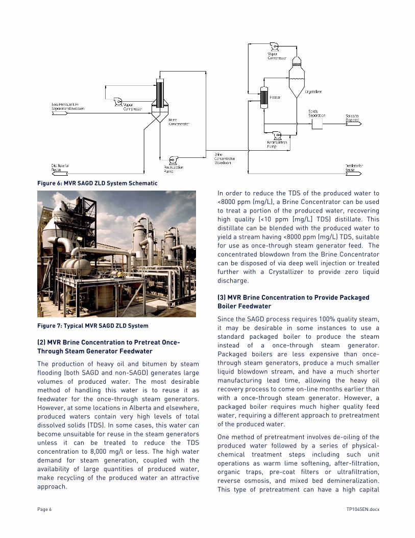
Table 1 presents a Brine Concentrator feed chemistry for this type of SAGD ZLD system. Figure 5 is a photograph of a ZLD system of the size required for a SAGD facility producing about 30,000 bpd of heavy oil, similar to that recently provided by SUEZ RCC for a SAGD facility in northern Alberta. If LP separator flash steam is not available, the Brine Concentrator and Crystallizer can operate using mechanical vapor recompression (MVR) technology. MVR evaporation and crystallization are economically attractive if a “free” or waste steam source, such as LP separator flash steam, is not available. A SAGD ZLD system using MVR technology is depicted in Figure 6. A photograph of an MVR ZLD system of the size required for a 30,000 bpd SAGD facility is shown in Figure 7.
Figure 5: Typical Steam Driven SAGD ZLD System
Page 6 TP1045EN.docx
Figure 6: MVR SAGD ZLD System Schematic
Figure 7: Typical MVR SAGD ZLD System
(2) MVR Brine Concentration to Pretreat Once-Through Steam Generator Feedwater
The production of heavy oil and bitumen by steam flooding (both SAGD and non-SAGD) generates large volumes of produced water. The most desirable method of handling this water is to reuse it as feedwater for the once-through steam generators. However, at some locations in Alberta and elsewhere, produced waters contain very high levels of total dissolved solids (TDS). In some cases, this water can become unsuitable for reuse in the steam generators unless it can be treated to reduce the TDS concentration to 8,000 mg/l or less. The high water demand for steam generation, coupled with the availability of large quantities of produced water, make recycling of the produced water an attractive approach.
In order to reduce the TDS of the produced water to <8000 ppm (mg/L), a Brine Concentrator can be used to treat a portion of the produced water, recovering high quality (<10 ppm [mg/L] TDS) distillate. This distillate can be blended with the produced water to yield a stream having <8000 ppm (mg/L) TDS, suitable for use as once-through steam generator feed. The concentrated blowdown from the Brine Concentrator can be disposed of via deep well injection or treated further with a Crystallizer to provide zero liquid discharge.
(3) MVR Brine Concentration to Provide Packaged Boiler Feedwater
Since the SAGD process requires 100% quality steam, it may be desirable in some instances to use a standard packaged boiler to produce the steam instead of a once-through steam generator. Packaged boilers are less expensive than once-through steam generators, produce a much smaller liquid blowdown stream, and have a much shorter manufacturing lead time, allowing the heavy oil recovery process to come on-line months earlier than with a once-through steam generator. However, a packaged boiler requires much higher quality feed water, requiring a different approach to pretreatment of the produced water.
One method of pretreatment involves de-oiling of the produced water followed by a series of physical-chemical treatment steps including such unit operations as warm lime softening, after-filtration, organic traps, pre-coat filters or ultrafiltration, reverse osmosis, and mixed bed demineralization. This type of pretreatment can have a high capital

TP1045EN.docx Page 7
cost, high chemical cost, high sludge disposal cost, requires frequent membrane replacement, and is quite labor intensive to operate and maintain. Therefore, it is desirable to use a simpler, more cost effective approach to produced water treatment for packaged boiler make-up water.
A more desirable method of produced water treatment for use with packaged boilers is MVR Brine Concentration followed by a polishing demineralizer. The Brine Concentrator will typically be operated in the seeded-slurry mode due to the presence of scaling salts and high silica levels in the produced water. A schematic of this process is presented in Figure 8. This method:
5. Eliminates physical-chemical produced water
treatment. 6. Provides lower capital and operating costs.
7. Does not produce softener sludge and minimizes the number of waste streams for disposal.
8. Requires fewer maintenance materials and less maintenance labor.
9. Reduces the amount of produced water de-oiling equipment required.
Figure 8: MVR Brine Concentrator Produced Water Pretreatment for Packaged Boiler Schematic
Page 8 TP1045EN.docx
The Brine Concentrator distillate (~2 ppm [mg/L] TDS) is fed into a polishing demineralizer system. The polished distillate is used as feedwater for the packaged boiler. The blowdown from the Brine Concentrator can be disposed of via deep well injection or can be further concentrated and/or crystallized using a Crystallizer, resulting in zero liquid discharge.
conclusions
Brine Concentration, Crystallization and Zero Liquid Discharge (ZLD) are proven technologies. RCC (now SUEZ) has over 100 installations worldwide, including the world’s first two SAGD ZLD systems in northern Alberta.
Brine Concentrators and Crystallizers are used to achieve ZLD in the SAGD industry when deep well injection is not possible due to geological constraints, potential contamination of fresh water aquifers, increasingly stringent regulatory requirements, and restrictions on the allowable amount of plant make-up water.
Seeded-slurry Brine Concentration is required in many cases to prevent scaling of evaporator heat transfer services.
Brine Concentrator and Crystallizer designs need to take into account the potentially high levels of water soluble organics present in produced waters.
Brine Concentrators are a cost effective and technically viable means of pretreating produced water for once-through steam generators in cases where produced water TDS is >8000 ppm (mg/L).
Brine Concentrators can be used to eliminate physical-chemical produced water pretreatment, and can allow for the replacement of once-through steam generators with packaged boilers for heavy oil recovery facilities.
Table 2: Nomenclature
references
HEINS, B., Case Study: Zero Liquid Discharge Wastewater Recycling System at Apache Nitrogen Products, prepared for presentation at the Ammonium Nitrate Producers Study Group, Sandestin, Florida, November 4-6, 1997.
SOLOMON, R.L., SCHOOLEY, K.E., and GRIFFIN, S.J., The Advantage of Mixed Salt Crystallizers in Zero Liquid Discharge Wastewater Treatment Systems, paper IWC-98-50, prepared for presentation at the International Water Conference, October 1998.
KOK, S. ZAIDI, A., and SOLOMON, R., Advances in Thermal Recovery: Total Dissolved Solids Removal from Water Produced During the In-Situ Recovery of Heavy Oil and Bitumen, The Journal of Canadian Petroleum Technology, Volume 28, No. 1, January-February 1989.