Embed Size (px)
Citation preview
ACI 307R-98
Commentary on Design and Construction ofReinforced Concrete Chimneys (AC1 307-98)
Reported by ACI Committee 307
Victor A. BochicchioChairman
David J. Bird Thomas Joseph
John J. Catty Jagadish R. Joshi
Brian Cooley Erick N. Larson
Phillip B. Davidson Robert A. Porthouse
Shu-Jin Fang Ronald E. Purkey
Milton Hartstein Scott D. Richart
This commentury discusses some of the backpwnd and consideration ojCommittee 307 in developing the provisicms contained in “Standard Prac-tice ,jiw the Design and Construction tf Rei&rced Concrete Chimneys(AC1 307-98).” The changes from the prevrous edition are noted. Twoappendices provide the derivation of the equations ,for nominal strengthand temperature stresses.
Keywords: chimneys; compressive strength; concrete construction; eatth-quake-resistant structures; formwork (construction); foundations; hightemperature; linings; loads (forces); moments; openings; precast concrete;quahty control; reinforced concrete; reinforcing steels; specifications;static loads; strength; structural analysis; structural design; temperature;thermal gradient; wind pressure.
CONTENTS
Introduction, p. 307R2
Chapter l-General, p. 307Fb3I . 1 -scope1 &-Reference standards
rAC1 Committee Reports, Guides, Standard Practices, andCommentaries are intended for guidance in planning, de-signing, executing, and inspecting construction. This doc-ument is intended for the use of individuals who arecompetent to evaluate the significance and limitationsof its content and recommendations and who will acceptresponsibility for the application of the material it con-tains. The American Concrete Institute disclaims any andall responsibility for the stated principles. The Institute shallnot be liable for any loss or damage arising therefrom.Reference to this document shall not be made in contractdocuments. If items found in this document are desiredby the Architect/Engineer to be a part of the contract doc-uments, they shall be restated in mandatory language forincorporation by the Architect/Engineer. i
Wadi S. Rumman
Randolph W. Snook
John C. Sowizal
Barry J. Vickery
Chung-Yee John Wei
Edward L. Yordy
Chapter 2-Materials, p. 307R3
Chapter 3-Construction requirements, p. 307R-33.3-Strength tests3.“Forms3.5--Reinforcing placement
Chapter 4-Service loads and general designcriteria, p. 307R-4
4. l-General4.2-Wind loads4.3-Earthquake loads4.5--Deflection criteria
Chapter 5-Design of chimney shell-Strengthmethod, p. 307R7
5. I--General5.4-Design strength5.5-Nominal moment strength5.dDesign for circumferential bending
Chapter S-Thermal stresses, p. 307R-96. I--General6.2-Vertical temperature stresses
Appendix A-Derivation of equations for nominalstrength, p. 307R-9
Appendix B-Derivation of equations fortemperature stresses, p. 307R-13
Appendix C-References, p. 307R-14
AC1 3071-98 supercedes AC1 3071-95 and becume effective November I. 1998.Copyright 0 1998, American Concrete Institute.All rights reserved including rights of reproduction and use m any form or by an)
means, including the making of copies by any photo process. or by electronic 01mechuul device, printed, written, or oral, or recording for sound or visual reproduc.tlon or for use tn any knowledge or retrieval system or device, unless permission j rwriting is obtamed from the copyright proprietors.
307R-2 MANUAL OF CONCRETE PRACTICE
INTRODUCTION the difficulty of selecting the proper safety and serviceabilityAs industry expanded in the years immediately following levels that might be desirable for various classes of construc-
World War I and as a result of the development of large pul- tion. Committee investigations revealed that with some ofverized coal-fired boilers for the electric power generating the modifications (such as the K factor), the base shear equa-utilities in the 192Os, a number of rather large reinforced tions developed by the Seismology Committee of the Struc-concrete chimneys were constructed to accommodate these tural Engineers’ Association of California (SEAOC) couldnew facilities. A group of interested engineers who foresawthe potential need for many more such chimneys and whowere members of the American Concrete Institute decided toembark upon an effort to develop a rational design criteriafor these structures. The group was organized into AC1 Com-mittee 505 (this committee was the predecessor of thepresent Committee 307) to develop such criteria in the early1930s.
Committee 505 submitted to the Institute a “ProposedStandard Specification for the Design and ‘Construction ofReinforced Concrete Chimneys,” an outline of which waspublished in the AC1 JOURNAL, Proceedings V. 30, Mar.-Apr. 1934. This specification was adopted as a tentativestandard in February 1936. Although this tentative standardwas never accepted by AC1 as a regular standard, it was usedas the basis for the design of many chimneys. As these chim-neys aged, inspections revealed considerable cracking.When the industrial expansion began following World WarII, other engineers recognized the need for developing an im-proved design specification for reinforced chimneys.
In May 1949, Committee 505 was reactivated to revise thetentative standard specification, embodying modificationsthat were found desirable during the years it had been in use.The section dealing with the temperature gradient throughthe chimney lining and the chimney shell was completely re-vised and extended to cover different types and thicknessesof linings and both unventilated and ventilated air spaces be-tween the lining and the concrete shell. In 1954, this specifi-cation was approved as AC1 505-54.
The rapid increase in the size and height of concrete chim-neys being built in the mid-1950s raised further questionsabout the adequacy of the 1954 version of the specification,especially as related to earthquake forces and the effects ofwind.
In May 1959, the AC1 Board of Direction again reactivat-ed Committee 505 (Committee 307) to review the standardand to update portions of the specification in line with the lat-est design techniques and the then-current knowledge of theseverity of the operating conditions that prevailed in largesteam plants. The material in the standard was reorganized,charts were added, and the methods for determining loadsdue to wind and earthquakes were revised. The informationon design and construction of various types of linings wasamplified and incorporated in an appendix. That specifica-tion included criteria for working stress design. It wasplanned to add ultimate strength criteria in a future revisionof this standard.
In preparing the earthquake design recommendations, theCommittee incorporated the results of theoretical studies byadapting them to existing United States codes. The primaryproblems in this endeavor stemmed from the uncertaintiesstill inherent in the definition of earthquake forces and from
be applied to chimneys. Similarly, the shape of the force,shear, and moment distributions, as revised in their 1967 re-port, were also suitable for chimneys. A use factor (U factor)ranging from 1.3 to 2.0 was introduced in the specificationand it was emphasized that the requirements of Section 4.5of AC1 307-69 relating to seismic design could be supersed-ed by a rational analysis based on evaluation of the seismic-ity of the site and modal response calculations. Themodifications were approved in 1969 and the specificationwas designated AC1 307-69. In that specification, the com-mentary and derivation of equations were published sepa-rately as a supplement to AC1 307-69.
In 1970, the specification was reissued with corrections oftypographical errors. This issue of AC1 307-69 was also des-ignated ANSI A158.1-1970. At the time, as a result of nu-merous requests, the commentary and derivation ofequations were bound together with the specification.
The 1979, revision of the specification updated its require-ments to agree with the then-accepted standard practice inthe design and construction of reinforced concrete chimneys.The major changes included the requirement that two layersof reinforcing steel be used in the walls of all chimneys (pre-viously this only applied to chimney walls thicker than 18in.) and the requirement that horizontal sections through thechimney wall be designed for the radial wind pressure distri-bution around the chimney. Formulas were included to com-pute the stresses under these conditions. Many revisions of aless important nature were included to bring the specificationup to date.
The editions of the specifications prior to 1979 includedappendices on the subjects of chimney linings and accesso-ries. In 1971, Committee 307 learned of buckling problemsin steel chimney liners. The Committee also noted that inmodem power plant and process chimneys, environmentalregulations required ‘treatment of the effluent gases thatcould result in extremely variable and aggressively corrosiveconditions in the chimneys. In view of these facts, the Com-mittee agreed that the task of keeping the chimney liner rec-ommendations current was not a responsibility of an AC1committee and could be misleading to designers using thechimney specification. It was the consensus of the Commit-tee that the reference to chimney liner construction bedropped from future editions of the specification. Recogniz-ing this, Committee 307 made a recommendation to theBrick Manufacturers’ Association and the American Societyof Civil Engineers that each appoint a task force or a com-mittee for the development of design criteria for brick andsteel liners, respectively. The Power Division of ASCE tookup the recommendation and appointed a task committee thatdeveloped and published in 1975 a design guide entitled,“Design and Construction of Steel Chimney Liners.” ASTM
REINFORCED CONCRETE CHIMNEYS COMMENTARY 307R-3
established two task forces for chimney liners, one for brickand the other for fiberglass reinforced plastic.
The Committee had extensive discussion on the questionof including strength design in the 1979 specification. Thedecision to exclude it was based on the lack of experimentaldata on hollow concrete cylinders to substantiate this form ofanalysis for concrete chimneys, However, the Committeecontinued to consider strength design and encouragedexperiments in this area.
Shortly after the 1979 edition was issued, the Committeedecided to incorporate strength design provisions and updatethe wind and earthquake design requirements.
The 1988 edition of AC1 307 incorporated significantchanges in the procedures for calculating wind forces as wellas requiring strength design rather than working stress. Theeffects of these and other revisions resulted in designs withrelatively thin walls governed mainly by steel area and, inmany instances, across-wind forces.
The subject of across-wind loads dominated the attentionof the Committee between 1988 and 1995 and the 1995 stan-dard introduied modified procedures to reflect more recentinformation and thinking.
Precast chimney design and construction techniques wereintroduced as this type of design became more prevalent forchimneys as tall as 300 ft.
The subject of noncircular shapes was also introduced in 1995.However, due to the virtually infinite array of possible configu-rations, only broadly defined procedures were presented.
Because of dissimilarities between the load factors re-quired by the AC1 307 standard and AC1 3 18, the Committeeadded guidelines for determining bearing pressures andloads to size and design chimney foundations.
In summary, the following highlights the major changesthat were incorporated into the 1995 standard:
l Modified procedures for calculating across-wind loads;* Added requirements for precast concrete chimney col-
umns;l Added procedures for calculating loads and for design-
ing noncircular chimney columns;l Deleted exemptions previously granted to “smaller” chim-
neys regarding reinforcement and wall thickness; and* Deleted static equivalent procedures for calculating
earthquake forces.
Synopsis of current revisionsRevisions to the ASCE 7-95 standard relating to wind and
seismic forces required that several changes be made to the1995 edition of AC1 307. The following highlights thechanges incorporated into the current standard:
l Site-specific wind loads are calculated using a “3~setgust” speed determined from Fig. 6-l in ASCE 7-95 in-stead of the previously used “fastest-mile” speed.
l Site-specific earthquake forces are calculated using theeffective peak velocity-related acceleration contoursdetermined from Contour Map 9-2 in ASCE 7-95 in-stead of previously designated zonal intensity.
l The vertical load factor for along-wind forces has beenreduced from 1.7 to 1.3.
l The vertical load factor for seismic forces has been re-duced from 1.87 to 1.43.
l The load factor for across-wind forces has been re-duced from 1.40 to 1.20.
l The vertical strength reduction factor $ has been re-duced from 0.80 to 0.70.
It should be noted that the reduced load factors must beused in concert with the revised strength reduction factor andthe wind and seismic loads specified in ASCE 7-95.
The foregoing revisions are discussed in more detail in thefollowing commentary.
Finally, the Committee believes that the AC1 307 standard isparticularly unique in its inclusion of specific procedures tocalculate wind and seismic forces on chimneys. Consequently,the Committee feels that the previous Commentary regardingthese subjects should be retained wherever possible.
Similarly, the Committee believes that the Commentaryregarding the assumptions and procedures for strength de-sign and other recent revisions should also be retained forreference.
A chapter-by-chapter commentary follows.
CHAPTER I-GENERAL1 .l-Scope
The scope of the 1995 standard was expanded to includeprecast chimney shells. Additional information may befound in PC1 manuals.1*2 Warnes3 provides further guide-lines on connection details for precast structures. Additionalinformation is given in AC1 550R, “Design Recommenda-tions for Precast Concrete Structures.”
1 J-Reference standardsThe year of adoption or revision for the referenced stan-
dards has been updated.
CHAPTER 2-MATERIALSNo changes of note have been made in this section.
CHAPTER 3--CONSfRUCTION REQUIREMENTS3.3-Strength tests
Requirements for testing precast concrete units were add-ed in the 1995 standard.
3.AFormsShear transfer within precast concrete shells must be con-
sidered in design especially if the structure has vertical aswell as horizontal construction joints.
3,!5-Reinforcing placementThe size, spacing, and location of vertical cores within
precast concrete chimney shells will be determined by geom-etry and steel area requirements. It is important that the de-sign of precast chimneys comply with the minimum spacingrequirements of AC1 3 18 when arranging reinforcementwithin the cores to permit proper bar splicing and concreteplacement.
307R-4 MANUAL OF CONCRETE PRACTICE
CHAPTER “ERVICE LOADSAND GENERAL DESIGN CRITERIA
4.1-GeneralThe 1995 Committee re-evaluated the previous exemp-
tions regarding two-face reinforcement and minimum wallthickness for chimneys 300 ft or less in height and less than20 ft in diameter. Recent information has indicated that two-face circumferential reinforcement is necessary to minimizevertical cracking due to radial wind pressures and reversethermal gradients due to the effects of solar heating. Reversethermal gradients due to solar heating may be more pro-nounced when the air space between the column and liningis purged by pressurization fans and gas temperatures arelow, Further, the 1995 Committee believed that two-face re-inforcement should be required in all chimney columns, re-gardless of size, considering the aggressive environmentsurrounding chimneys.
4.1.3.1-A minimum wall thickness of 8 in. (7 in. if pre-cast) is required to provide for proper concrete placementwithin and around two curtains of reinforcement.
4.1.3.2---The 1995 Committee expressed concern re-garding edge buckling of relatively thin walls through re-gions where tall openings are present. The simplifiedprocedure given in this section will give approximately thesame results as the procedures of Chapter 10.10 of AC1 3 18.
If jamb buttresses are used, it is recommended that they bepoured homogeneously with the section or adequately tied toensure composite action.
4.1.7.~Foundation design: The loading combinationsin the 1995 version of this article have been deleted. Thepsuedo-bearing pressure/pile loads shall be computed bymultiplying the unfactored dead and axial bending loads bytheir appropriate load factor from Sections 5.3.1 and 5.3.2.
4.2--Wind loads4.2.1 General-The basic wind speed V in the current
standard has been revised from “fastest-mile” to a “3-setgust” speed to reflect the changes published in ASCE 7-95.Eq. (4-l) has been modified accordingly. In Eq. (4-l), 1.47converts wind speed from mph to ft/sec and 0.65 converts 3-set gust speed to a mean hourly speed. The revised powerlaw coefficient 0.154 (as an approximation of l/6.5) comesfrom Table C6-6 in the Commentary to ASCE 7-95, for Ex-posure C and for flexible or dynamically sensitive structures;the increase in the exponent increases the calculated pres-sures over the chimney height for the same speed.
The “3-set gust” speed is always higher than the previous-ly specified “fastest-mile” speed. A “fastest-mile” windspeed may be converted to a “3-set gust” speed for normalspeeds of interest in chimney design using the followingequation
3-set gust V = 1.0546 (fastest mile V + 11.94)
The relationship between 3-set gust speed and-any otheraveraging time can be found in texts such as Wind Effects onStructures4 by Simiu and Scanlon.
The procedure was determined from simplified dynamicanalyses that yield equivalent static load distributions. Thisapproach requires that a wind speed averaged over a periodon the order of 20 min to 1 hr be used as a basis for design.Eq. (4-l) permits the mean hourly speed at height z to bedetermined from the basic design speed that is the “3-setgust” speed at 33 ft over open country. The conversion isbased on the relationship recommended by Hollister5 Thespecified wind loads presume that the chimney is located inopen country. In rougher terrains the overall loads will be re-duced, but for a tall chimney (height on the order of 650 ft)the reduction is not likely to exceed 20 percent.
VR in Eq. (4-l) is the product of the square root of the im-portance factor I and V, the basic wind speed as charted anddefined in ASCE 7-95. It should be noted that I can be usedto vary probability, as well as to classify the importance ofthe structure. The Committee believes that all chimneysshould be designed to be part of an essential facility classi-fied as a Category IV structure. The importance factor of1.15 for Category IV buildings and structures corresponds toa mean recurrence interval of 100 years. Additional informa-tion can be found in ASCE 7-95.
The simplified provisions of this standard do not precludethe use of more detailed methods, and the results of a full dy-namic analysis employing accepted approaches and recog-nizing the flow profile and turbulence levels at a specific sitemay be used in place of the standard provisions. The approx-imate methods have, however, been tested against more de-tailed analyses, using probablisti&’ and deterministic 8
approaches. These methods yielded acceptable results.4.2.2 Along-wind loads---The recommended drag coeffi-
cients are consistent with slender chimneys [h/d(h) > 201with a relative surface roughness on the order of lOA to 10e5.Some reduction in the drag coefficient C,, with decreasing Wd(h) can be expected but unusually rough (e.g., ribbed) chim-neys would have higher values of Cdr. The variations of Cd,.with roughness and aspect ratio are discussed by Basu’ andVickery and Basu.”
The total load per unit length is computed a_s the sum ofthe mean component W(z) and the fluctuating componentw’(z). The dynamic component was evaluated using aslightly modified form of the “gust factor” approaches de-scribed by Davenport,” Vickery,6 and Simiu.12 The basemoment is evaluated using the gust factor approach but theloads producing this moment are approximated by a trian-gular distribution rather than a distribution matching themean. Eq. (4-6) is a simple empirical fit to values of G,)computed as before for a structural damping of 1.5 percentof critical. Except for referencing Vas the 3-set gust speed,no revisions have been made to the procedures for calculat-ing along-wind loads.
The natural period of the chimney may include the effectof foundation springs.
4.2.3Acros.vwind loads--No revisions have been made tothe procedures for calculating across-wind forces, However,Eq. (4-8a) has been rewritten for simplification and severaltypographical errors were corrected.
REINFORCED CONCRETE CHIMNEYS COMMENTARY 307R-5
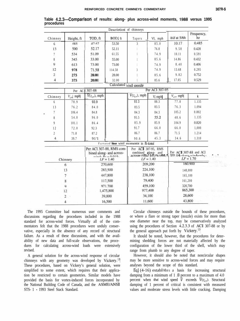
Table 4.2.3-Comparison of results: along- plus across-wind moments, 1999 versus 1995procedures
DescritXion of chimneys
Chimney6
VI, mph8 5 . 076.87 4 . 98 5 . 67 4 . 97 4 . 98 5 . 685.6
Tapers31111311I
vind s~ppd-1.
BOD, ft53.5052.1161.5555.0073.00
114.5828.0032.00
T 9 . 5 8 0.42810.11 0.59114.86 0.432
8 . 4 0 0.40613.68 0.2959 . 8 2 0.752
17.05 0.529
5 3 4 51.0954s 33.006 1 3 73.00
i
9 7 8 71-502 7 5 28.003 7 5 20.00
78
Per AC
Vcrl mph7 8 . 97 6 . 2106.45 4 . 0101.17 2 . 071.839.7
Vcr3 mph k7 7 . 8 1.1357 6 . 3 1.094105.2 0.8024 8 . 6 1.135104.9 0.8206 6 . 0 1,00071.5 1.2143 4 . 6 1.310
V; mph88.383.584.355-285.96 6 . 086.74 5 . 3
Chimney61 3
h 789
93 .3
83.584.395.58 5 . 991.786.79 0 . 6
93.98 4 . 084.89 6 . 08 6 . 492.387.291‘1 ,
-
1 22
Factored base wind mOmentS in ft-tOnSPer AC1 307-95, RMScombined along- and Per AC1 307-M and ACI9(.rnp” . . . . . ..I. a.
- n n1 n. WTXCK -lnnn-tuinrl nnlv*
148,000165,100161,200320,700
Circular chimneys outside the bounds of these procedures,or where a flare or strong taper (nozzle) exists for more thanone diameter near the top, may be conservatively analyzedusing the procedures of Section 4.2.3.3 of AC1 307-88 or bythe general approach put forth by Vickery.13
It should be noted, however, that the procedures for deter-mining shedding forces are not materially affected by theconfiguration of the lower third of the shell, which mayrange from plumb to any degree of taper.
However, it should also be noted that noncircular shapesmay be more sensitive to across-wind forces and may requireanalyses beyond the scope of this standard.
Eq. (4-16) establishe s a basis for increasing structuraldamping from a minimum of 1 .O percent to a maximum of 4.0percent when the wind speed v exceeds ~(z,,). Structuraldamping of 1 percent of critical is consistent with measuredvalues and moderate stress levels with little cracking. Damping
The 1995 Committee had numerous user comments anddiscussions regarding the procedures included in the 1988standard for across-wind forces. Virtually all of the com-mentators felt that the 1988 procedures were unduly conser-vative, especially in the absence of any record of structuralfailure. As a result of these discussions, and with the avail-ability of new data and full-scale observations, the proce-dures for calculating across-wind loads were extensivelyrevised.
A general solution for the across-wind response of circularchimneys with any geometry was developed by Vickery.t3These procedures, based on Vickery’s general solution, weresimplified to some extent, which requires that their applica-tion be restricted to certain geometries. Similar models haveprovided the basis for vortex-induced forces incorporated bythe National Building Code of Canada, and the ASMEJANSISTS- 1 - 1993 Steel Stack Standard.
307R-6 MANUAL OF CONCRETE PRACTICE
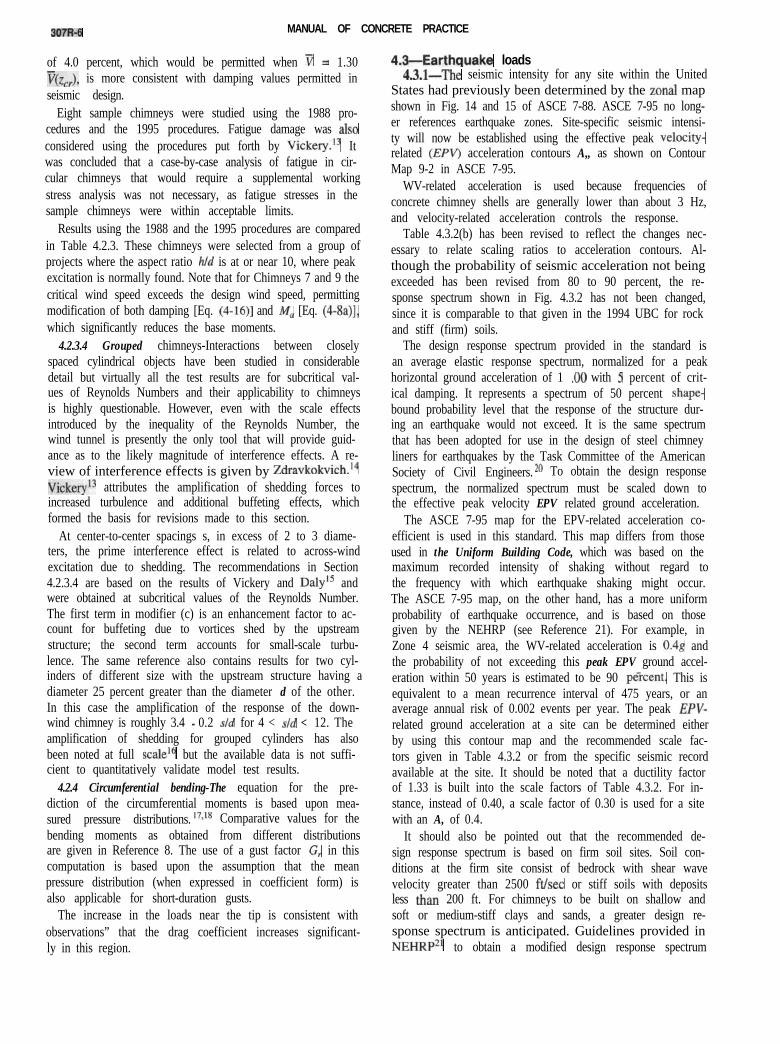
of 4.0 percent, which would be permitted when v = 1.30v(z,,), is more consistent with damping values permitted inseismic design.
Eight sample chimneys were studied using the 1988 pro-cedures and the 1995 procedures. Fatigue damage was alsoconsidered using the procedures put forth by
h/d is at or near 10, where peakexcitation is normally found. Note that for Chimneys 7 and 9 thecritical wind speed exceeds the design wind speed, permittingmodification of both damping [Eq. (4-16)] and iW, [Eq. (4-8a)],which significantly reduces the base moments.
4.2.3.4 Grouped chimneys-Interactions between closelyspaced cylindrical objects have been studied in considerabledetail but virtually all the test results are for subcritical val-ues of Reynolds Numbers and their applicability to chimneysis highly questionable. However, even with the scale effectsintroduced by the inequality of the Reynolds Number, thewind tunnel is presently the only tool that will provide guid-ance as to the likely magnitude of interference effects. A re-view of interference effects is given by Zdravkokvich.14Vickeryr3 attributes the amplification of shedding forces toincreased turbulence and additional buffeting effects, whichformed the basis for revisions made to this section.
At center-to-center spacings s, in excess of 2 to 3 diame-ters, the prime interference effect is related to across-windexcitation due to shedding. The recommendations in Section4.2.3.4 are based on the results of Vickery and Daly” andwere obtained at subcritical values of the Reynolds Number.The first term in modifier (c) is an enhancement factor to ac-count for buffeting due to vortices shed by the upstreamstructure; the second term accounts for small-scale turbu-lence. The same reference also contains results for two cyl-inders of different size with the upstream structure having adiameter 25 percent greater than the diameter d of the other.In this case the amplification of the response of the down-wind chimney is roughly 3.4 - 0.2 sld for 4 < sld < 12. Theamplification of shedding for grouped cylinders has alsobeen noted at full scaleI but the available data is not suffi-cient to quantitatively validate model test results.
4.2.4 Circumferential bending-The equation for the pre-diction of the circumferential moments is based upon mea-sured pressure distributions. 17*lR Comparative values for thebending moments as obtained from different distributionsare given in Reference 8. The use of a gust factor G, in thiscomputation is based upon the assumption that the meanpressure distribution (when expressed in coefficient form) isalso applicable for short-duration gusts.
The increase in the loads near the tip is consistent withobservations” that the drag coefficient increases significant-ly in this region.
4.SEarthquake loads4.3.1-The seismic intensity for any site within the United
States had previously been determined by the zonal mapshown in Fig. 14 and 15 of ASCE 7-88. ASCE 7-95 no long-er references earthquake zones. Site-specific seismic intensi-ty will now be established using the effective peak velocity-related (WV) acceleration contours A,, as shown on ContourMap 9-2 in ASCE 7-95.
WV-related acceleration is used because frequencies ofconcrete chimney shells are generally lower than about 3 Hz,and velocity-related acceleration controls the response.
Table 4.3.2(b) has been revised to reflect the changes nec-essary to relate scaling ratios to acceleration contours. Al-though the probability of seismic acceleration not beingexceeded has been revised from 80 to 90 percent, the re-sponse spectrum shown in Fig. 4.3.2 has not been changed,since it is comparable to that given in the 1994 UBC for rockand stiff (firm) soils.
The design response spectrum provided in the standard isan average elastic response spectrum, normalized for a peakhorizontal ground acceleration of 1 .OO with 5 percent of crit-ical damping. It represents a spectrum of 50 percent shape-bound probability level that the response of the structure dur-ing an earthquake would not exceed. It is the same spectrumthat has been adopted for use in the design of steel chimneyliners for earthquakes by the Task Committee of the AmericanSociety of Civil Engineers. 2o To obtain the design responsespectrum, the normalized spectrum must be scaled down tothe effective peak velocity EPV related ground acceleration.
The ASCE 7-95 map for the EPV-related acceleration co-efficient is used in this standard. This map differs from thoseused in the Uniform Building Code, which was based on themaximum recorded intensity of shaking without regard tothe frequency with which earthquake shaking might occur.The ASCE 7-95 map, on the other hand, has a more uniformprobability of earthquake occurrence, and is based on thosegiven by the NEHRP (see Reference 21). For example, inZone 4 seismic area, the WV-related acceleration is 0.4g andthe probability of not exceeding this peak EPV ground accel-eration within 50 years is estimated to be 90 peicent. This isequivalent to a mean recurrence interval of 475 years, or anaverage annual risk of 0.002 events per year. The peak EPV-related ground acceleration at a site can be determined eitherby using this contour map and the recommended scale fac-tors given in Table 4.3.2 or from the specific seismic recordavailable at the site. It should be noted that a ductility factorof 1.33 is built into the scale factors of Table 4.3.2. For in-stance, instead of 0.40, a scale factor of 0.30 is used for a sitewith an A, of 0.4.
It should also be pointed out that the recommended de-sign response spectrum is based on firm soil sites. Soil con-ditions at the firm site consist of bedrock with shear wavevelocity greater than 2500 ftisec or stiff soils with depositsless than 200 ft. For chimneys to be built on shallow andsoft or medium-stiff clays and sands, a greater design re-sponse spectrum is anticipated. Guidelines provided inNEHRP*l to obtain a modified design response spectrum
Vickery.‘s Itwas concluded that a case-by-case analysis of fatigue in cir-cular chimneys that would require a supplemental workingstress analysis was not necessary, as fatigue stresses in thesample chimneys were within acceptable limits.
Results using the 1988 and the 1995 procedures are comparedin Table 4.2.3. These chimneys were selected from a group ofprojects where the aspect ratio
REINFORCED CONCRETE CHIMNEYS COMMENTARY
and the soil-structure interaction may be used. reached first. If the steel fracture limit is reached firIn place of a dynamic response spectrum analysis, a time
history dynamic analysis is permitted, provided a reliabletime history of earthquake ground motion is used.
In the design of a chimney for horizontal earthquake forces,only one horizontal direction need be considered. Unlikebuilding structures, chimneys are generally axisymmetric, andthe orthogonal effects from two horizontal earthquakes actingsimultaneously in the two principal directions are negligible.
The effect of the vertical component of the earthquake onthe chimney has been determined to be of no design signifi-cance. An extensive time history analysis made by the Com-mittee shows that the vertical stresses from dead load andhorizontal seismic excitation are increased by at most a fewpercent by the effects of vertical seismic excitations. This isprincipally because the psa responses to vertical and hori-zontal acceleration do not occur simultaneously.
Design based on SRSS of vertical and horizontal earthquakeforces will be unduly conservative. Therefore, the inclusion ofvertical seismic effects is not recommended by the Committee.
For cases in which the chimney lining (brick, steel, or oth-er materials) is supported by the concrete chimney shell, ei-ther at the top of the chimney shell or at other intermediatepoints, a dynamic analysis including both concrete shell andliner should be used. Appropriate damping values should beused for the liner depending on its construction (e.g., 1.5 per-cent for steel liners, 4.0 percent for brick liners, and 2.0 per-cent for fiber reinforced plastic liners).
4.5-Deflection criteriaThe incorporation of the strength design method into the
standard will generally result in chimneys with thinner wallsin the lower portion and with higher deflections. The Com-mittee felt that deflections under service loads should bechecked and that the deflections of chimneys designed by thestrength method should not vary greatly from the deflectionsof existing chimneys designed by the working stress method.Limiting deflections also serves to reduce tbe effects of sec-ondary bending moments.
However, the procedures in the AC1 307 1988 editionwere found to be too restrictive for shorter chimneys andwere modified in the 1995 standard. The deflection limit iscompared against the deflection calculated using untrackedconcrete sections and a fixed base.
Operation, access for inspection, lining type, etc., as wellas wind or earthquake-induced deflection, should be consid-ered when establishing shell geometry.
CHAPTER !&DESIGN OF CHIMNEY SHELL-STRENGTH METHOD
5.1-GeneralSeveral significant revisions were made to this section,
most notably the load factors specified in 5.3 and the strengthreduction factor $ specified in 5.4. Portions of previouscommentary are, however, retained for reference.
5.1.2 The maximum compressive strain in the concrete isassumed to be 0.003, or the maximum tensile strain in thesteel is assumed to be the fracture limit of 0.07, whichever is
maximum concrete strain computed from the linear stragram is below 0.003. This deviates from the design astions of AC1 318. For a given total vertical steel ratimay occur when the ratio of the vertical load to the mlis below a certain value. A total vertical steel ratiochimney cross section less than that per the minimuquirement of AC1 3 18 for flexural members is permitt
Even when the maximum concrete compressive stris less than 0.003, the stress block is still considered rgular. However, in these instances, the stress level istied by a correction factor called the parametercommentary on Section 5.5.1.
5.3.1--The Committee noted that the “fastest-mile” provi-sions in the 1988 edition of AC1 307 resulted in an increasein wind moments of between 0 and 50 percent when com-pared with AC1 307-79. The use of a “3-set gust” wind speedresults in further increases in axial bending moments, whichare 10 to 20 percent higher than moments calculated using“fastest-mile” speeds, Since the Committee has no data or in-formation concerning axial bending failures of chimneyshells designed using previously established procedures, itwas decided that the load factor for along-wind loads can besafely reduced from 1.7 to 1.3 when ‘<3-set gust” windspeeds are used. It should be noted that a wind load factor of1.3 is consistent with that recommended by ASCE 7-95.
Similarly, the Committee has determined that the windload factor for along, plus across-wind loads can be reducedfrom 1.4 to 1.2.
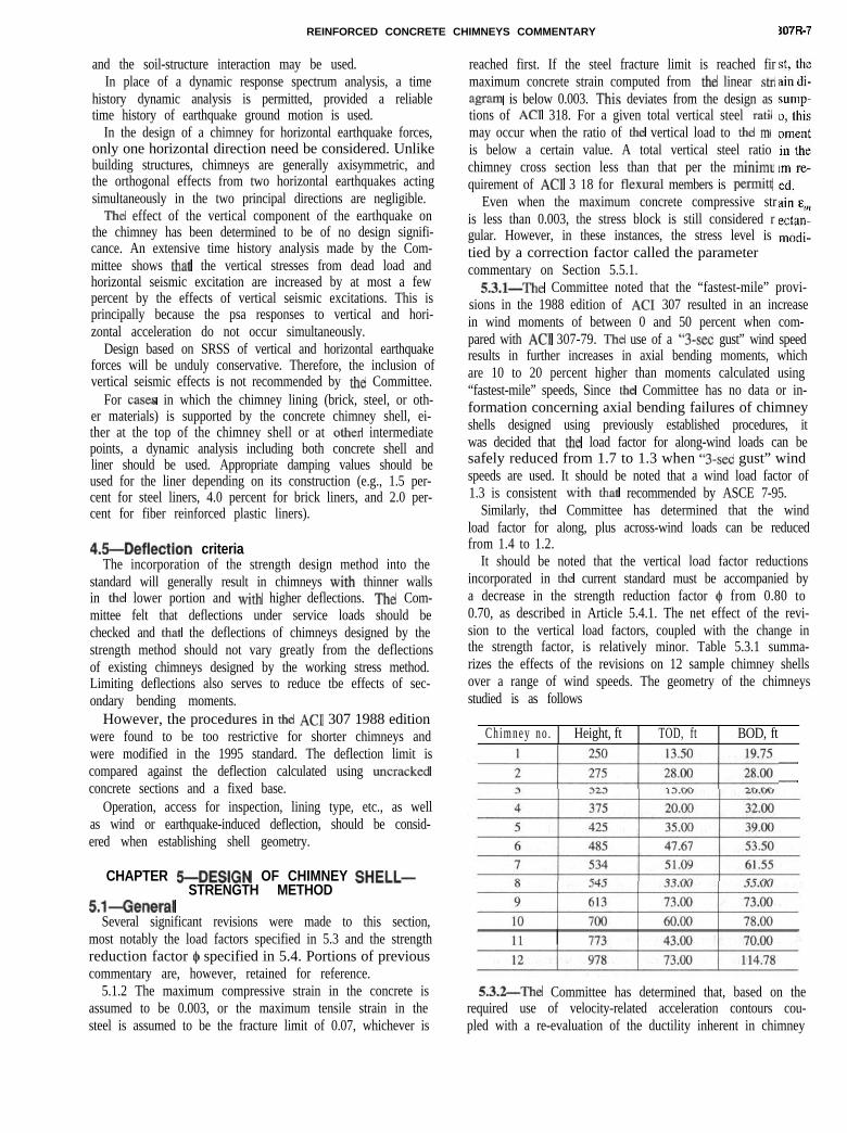
It should be noted that the vertical load factor reductionsincorporated in the current standard must be accompanied bya decrease in the strength reduction factor $ from 0.80 to0.70, as described in Article 5.4.1. The net effect of the revi-sion to the vertical load factors, coupled with the change inthe strength factor, is relatively minor. Table 5.3.1 summa-rizes the effects of the revisions on 12 sample chimney shellsover a range of wind speeds. The geometry of the chimneysstudied is as follows
Chimney no . Height, ft TOD, ft BOD, ft
--
5,3.2-The Committee has determined that, based on therequired use of velocity-related acceleration contours cou-pled with a re-evaluation of the ductility inherent in chimney
307R-a MANUAL OF CONCREYE PRACTICE
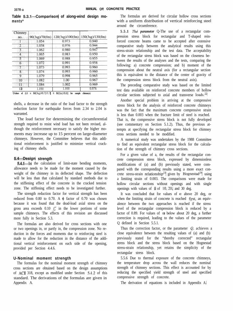
Table 5.3.1-Comparison of along-wind design mo-ments*
I
12 / 1.090 1.008 0.976‘(Values of (1.3 x M(3q)/O.7]/1.7 x M(fm)/O.R] for sample chimneys)
shells, a decrease in the ratio of the load factor to the strengthreduction factor for earthquake forces from 2.34 to 2.04 iswarranted.
The load factor for determining the circumferentialstrength required to resist wind load has not been revised, al-though the reinforcement necessary to satisfy the higher mo-ments may increase up to 15 percent on large-diameterchimneys. However, the Committee believes that this addi-tional reinforcement is justified to minimize vertical crack-ing of chimney shells.
5.4-Design strength5,4.1-In the calculation of limit-state bending moments,
allowance needs to be made for the moment caused by theweight of the chimney in its deflected shape. The deflectionwill be less than that calculated by standard methods due tothe stiffening effect of the concrete in the cracked tensionzone. The stiffening effect needs to be investigated further.
The strength reduction factor for vertical strength has beenreduced from 0.80 to 0.70. A $ factor of 0.70 was chosenbecause it was found that the dead-load axial stress on thegross area exceeds 0.10 f,’ in the lower portions of somesample chimneys. The effects of this revision are discussedmore fully in Section 5.3.
The formulas are also derived for cross sections with oneor two openings in, or partly in, the compression zone. No re-duction in the forces and moments due to reinforcing steel ismade to allow for the reduction in the distance of the addi-tional vertical reinforcement on each side of the opening,provided per Section 4.4.6.
U-Nominal moment strengthThe formulas for the nominal moment strength of chimney
cross sections are obtained based on the design assumptionsof AC1 318, except as modified under Section 5,1.2 of thisstandard. The derivations of the formulas are given inAppendix A.
The formulas are derived for circular hollow cross sectionswith a uniform distribution of vertical reinforcing steelaround the circumference.
5.5.1 The parameter Q-The use of a rectangular com-pression stress block for rectangular and T-shaped rein-forced concrete beams came to be accepted after extensivecomparative study between the analytical results using thisstress-strain relationship and the test data. The acceptabilityof the rectangular stress block was based on the closeness be-tween the results of the analyses and the tests, comparing thefollowing: a) concrete compression; and b) moment of thecompression about the neutral axis (for a rectangular sectionthis is equivalent to the distance of the center of gravity ofthe compression stress block from the neutral axis).
The preceding comparative study was based on the limitedtest data available on reinforced concrete members of hollowcircular sections subjected to axial and transverse loads.22
Another special problem in arriving at the compressivestress block for the analysis of reinforced concrete chimneyswas the fact that the maximum concrete compressive strainis less than 0.003 when the fracture limit of steel is reached.That is, the compressive stress block is not fully developed(see commentary on Section 5.1.2). Thus, the previous at-tempts at specifying the rectangular stress block for chimneycross sections needed to be modified.
A numerical study was undertaken by the 1988 Committeeto find an equivalent rectangular stress block for the calcula-tion of the strength of chimney cross sections.
For a given value of a, the results of the rectangular con-crete compression stress block, expressed by dimensionlessmodifications of (a) and (b) previously stated, were com-pared with the corresponding results using a more exact con-crete stress-strain relationship23 given by Hognestad24 usinga limiting strain of 0.003. The comparisons were made forhollow circular sections without openings and with singleopenings with values of B of 10,20, and 30 deg.
It was concluded that for values of c1 above 20 deg, orwhen the limiting strain of concrete is reached first, an equiv-alence between the two approaches is reached if the stresslevel of the rectangular compression block is reduced by afactor of 0.89. For values of 01 below about 20 deg, a furthercorrection is required, leading to the values of the parameterQ defined in Section 5.5.1.
Thus the correction factor, or the parameter Q, achieves aclose equivalence between the resulting values of (a) and (b)previously stated for the “thereby corrected” rectangularstress block and the stress block based on the Hognestadstress-strain relationship, yet retains the simplicity of therectangular stress block.
5.5.6 Due to thermal exposure of the concrete chimneys,the temperature drop across the wall reduces the nominalstrength of chimney sections. This effect is accounted for byreducing the specified yield strength of steel and specifiedcompressive strength of concrete.
The derivation of equations is included in Appendix A,
REINFORCED CONCAETE CHIMNEYS COMMENTARY 3071
5.6-Design for circumferential bending5.6.2 The commentary on Section 5.5.6 applies equally to
this section.
CHAPTER CTHERMAL STRESSES6.1--General
The derivations of the formulas for the vertical and hori-zontal stresses in concrete and steel, due to a temperaturedrop only across the chimney wall, are given in Appendix B.No revisions have been made to this section.
6.2-Vertical temperature stresses6.2.2 The research data available to establish the coeffi-
cients of heat transfer through chimney lining and shell, es-pecially as they concern the heat transfer from gases to thesurfaces and through ventilated air spaces between liningand shell, are somewhat meager. Unless complete heat bal-ance studies are made for the particular chimney, it is per-missible to use constants as determined or stated in thisstandard.
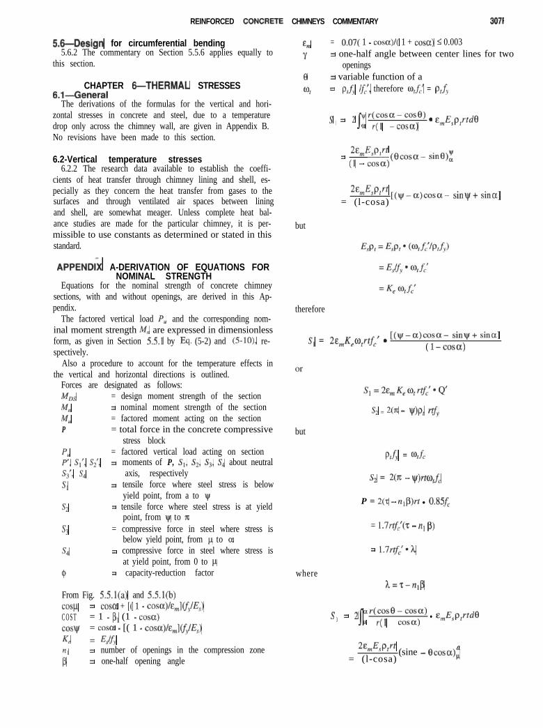
APPENDk A-DERIVATION OF EQUATIONS FORNOMINAL STRENGTH
Equations for the nominal strength of concrete chimneysections, with and without openings, are derived in this Ap-pendix.
The factored vertical load P, and the corresponding nom-inal moment strength M,, are expressed in dimensionlessform, as given in Section 5.5.1 by Eq. (5-2) and (5lo), re-spectively.
Also a procedure to account for the temperature effects inthe vertical and horizontal directions is outlined.
Forces are designated as follows:
MLX = design moment strength of the section
Mn = nominal moment strength of the section
MU = factored moment acting on the sectionP = total force in the concrete compressive
stress block
PU = factored vertical load acting on sectionP’, St’, S,‘, = moments of P, Sr, S,, Ss, S, about neutralS3’r s4 axis, respectively
Sl = tensile force where steel stress is belowyield point, from a to \~r
s2 = tensile force where steel stress is at yieldpoint, from \Ir to n:
s3 = compressive force in steel where stress isbelow yield point, from P to a
s4 = compressive force in steel where stress isat yield point, from 0 to P
e = capacity-reduction factor
From Fig. 5.5.1(a) and 5.5.1(b)cosp = cosa + [( 1 - cosa)/&,](f~EJC O S T = 1 - p, (1 - cosa)cosyl = cosa - [( 1 - COSCX)/&,]Cf~E~)
Ke = 44&nl = number of openings in the compression zone
P = one-half opening angle
%I = 0.07( 1 - cosa)l( 1 + coscr) I 0.003
Y = one-half angle between center lines for twoopenings
8 = variable function of a
64 = P,fY lf,‘, therefore o,fi = p,f,
s = 2 r(cosa-cod)1
I”a r(1 -cosa)* e,E,p,rt&
%,E,wt= (1 _ cosa)(B~~~a- sine):
2%&v-t= (l-cosa)
[(pr-cx)cosa- sinW+ sina]
but
therefore
S, = 2&,Kp,rtf, * [(yr-cc)cosa- sinW+ sina]( 1 - COW)
s2 = 2(x - WP, rtfy
but
Ptfy = %fc
& = 2(7c - yr)rtqfC
P = 2(2 - n,p)rt l O.SSf,
= 1.7rf:(2 - nr p)
= 1.7?$;*1
whereh=z-nlp
s3
= 2 ar(cose-cosC1)IP r(1 - cosa)
l &,E,p,rtdB
%,,E,P,rt a= (l-cosa)
(sine - Ocosa)l,
307R-10 MANUAL OF CONCRETE PRACTICE
= 2E,KeW,rtfct l [sina- siw- (a-PL)cosal(1 - cosa)
Sum of vertical forces must equal zero, therefore
P, = P + s, + s4 - s, - s,
= 1.7Ortf,‘h + 2&, K, O, r&‘Q3 + 20, rtf,‘p
- 2&, K, o, rrfc’Q’ - 20, rt&‘(a - I@
P,lrtf~ = K,
= 1.70h + 2&,K&(Q3 - Q’) +2NP - CR - WI
= 1.70h + 2&, Ke o, Ql + 20, hI
where
h=z-n,p
s f = 21
~r2(cosa~cose)2~Ea r(1 - cosa)
Eprtdem s t
2q,,E,r*p,t!(l- I”cosa) a
(cos*a- 2cosacos0 + cos*tI)dCI
2q,,Keqr2tfC’=(l l- cos a)
(v - a)cos*a - ‘tcosa(sinW - sina) + (V&y - a)+ ( ‘/4)(sin 2\v - sin 2a)]
J=[ 1
I, - a)cos2a + 2 sina cosa - 2 cosa siny(l/$siny cosv - (‘/*)sina cosa + (‘/*)(y - a)
2.J = 2&f - a)cos*a + 3sina cosa - 4cosa sinyc sinty cosy + (y - a)
therefore
where
J1 = W/(1 - cosa)
o r
J, = [2(y~ - cx)cos*a + 3sina cosa - 4cosa sinv+ siny cos\lr + (y - a)]/( 1 - cosa)
S,’ = 2I
Fptrtfy l r(cosa- cose)dO
= 2&+t& (Bcosa- sine);
= 2?pt tfy[(n - w>cosa + siny]
but
PSy = @tf,
therefore
S,l = 2?tf,‘otJ2
where
J2 = (IT - ~)cosa + siny
l q,,E,p,rtde
2q,,Kp,r*tf,’= ( l - c o s a ) J2
cos*CI - 2cosesina + cos*a)de
2%K,Wtr2tfC’ ‘= ( l - c o s a ) (
g + sin28- - 2cosasin0 + Ocos*a2 4 1
a
P
= ( l - c o s a ) ’
I(1/2Xa - p) + (‘14)(sin2a - sin2p) - 2cosa(sina - sinp)+ (a - p)cos2a]
Let
J3 = 2[ ]/( 1 - cosa)
o r
J3 = [a - p + sina cosa - sinp cosp - 4cosa(sina - sinp)+ 2(a - p)cos*a]/( 1 - cosa)
therefore
REINFORCED CONCRETE CHIMNEYS COMMENTARY 307Ra
s,’ -. 2f;p,rt&. r(cose - cosa)dO
For two openings in compression zone
nl =2
= 2r2p,tfY 0 (sin0 - Bcosa)!
= 2rZp, tfy (sinp - pcosa)
therefore
where
Sum of moments about neutral axis must equal zero, thefore
M, = P,rcosa + p’ + S,’ + S2’ + &’ + S4’
= PJCOS~ + 1.7O?tf,‘R + &,?tf,‘Kew,(J1 + J3)+ 3%34(J2 + 54)
J4 = sinp - pcosa
For P with one opening in compression zone [Fig.5.5.1(a)]
a.P’ = 2&.85f,’ l
[( rsincz --rcosa r( cos 0 - cos a)deT 3
= l.70r2tfc’(sinz - zcosa - sit@ + pcosa)
therefore
P = 1.70?21f,‘[sinz - (z - p)cosa - sit@
For P’ with two openings in compression zone [Fig.5.5.1(b)]
P’ = 2rtO.85&’ l
[( rsinz‘1: --rcosaz
; r( cos 8 - cos a)de 1= 1.70?2tf,‘[sinT - ‘ccosa - sin(y + p) + sin(y - 0) + ‘Lpcosa]
therefore
P = 1.701-2tf,‘[sinT - (z - 2P)cosa - sin(y + p) + sin(y - 6)
Generalizing
where
P’ = 1.70+&’ l R
R = sinz - (T - nlp)cosa - (n,/2)[sin(y+ p) - sin(y- p)]
For no openings
nl=y=@=O
For one opening in compression zone
nl = 1
therefore
M,,l??tf,’ = (P,cosah&‘) + K2
where
K2 = 1.7OR + &,Keot(JI + J3) + 2q(J2 + J4)
or
K2 = 1.7OR + &,K,qQ2 + 2qK
Q2 = [(ye - p)( 1 + 2cos’a) + (‘/,)(4sin2a + sin2u/ - sin2j.t)
- 4cosa(sina + sinyr - siny)]/( 1 - cosa)
and
K = sinv + sinp + (n: - v - jA)coSa
Multiply both sides of the equation by l/K, = r&‘/P,
therefore
K3 = M,,lPg = coscx + KzIKl
o r
and require
M, = K3P,,r
For two symmetric openings partly in compressic[Fig.5.5.l(c)]
y+P>z
and
Y-P<7
let
?3==y-/3
m zone
The situation is the same as for no openings in the com-pression zone with
2=6
h=6
R = sir& - &osol
and all other values are the same as before.Openings in the tension zone-Openings in the tension
zone are ignored since the tensile strength of the concrete isneglected, and the bars cut by the openings are replaced atthe sides of the openings.
Openings in the compression zone-Openings in the com-pression zone are ignored in calculations of the forces in thecompression reinforcement only, since the cut bars are re-placed at the sides of the openings.
Verh’cal temperature stresses in reinforcement; effect on fy
fsTv = tensile temperature stress in outside steel
fh' compressive temperature stress in inside steelfSrv andf’& at service loads
P=lPC1 + Yl) 1 +Yl
= ratio, outside steel area to total steel area
YIP Yl=PC1 +I$) 1 +Yl
=: ratio, inside steel area to total steel area
F,(v) = load factor for temperature combined with W or E= 1.4
At ultimate, efSect on fY on windward sideUsable yield force = yield force - F,(v) l tensile force in
outside steel + F,(v) * compressive force in inside steelDividing by total steel area A,
F,W--l---1 +YI
l A, l fSTV
f,‘(v) = fy - +As
therefore
3CRETE PRACTICE
It is conservative and convenient to use the same value forfy’ on the leeward side as well.
Vertical temperature stresses in concrete e#ect on f,’
f’bv = concrete compressive stress due to temperaturealone at service loads
At ultimate, effect on f,’ is
fc”W =f,’ - F,(v) l f’&‘v
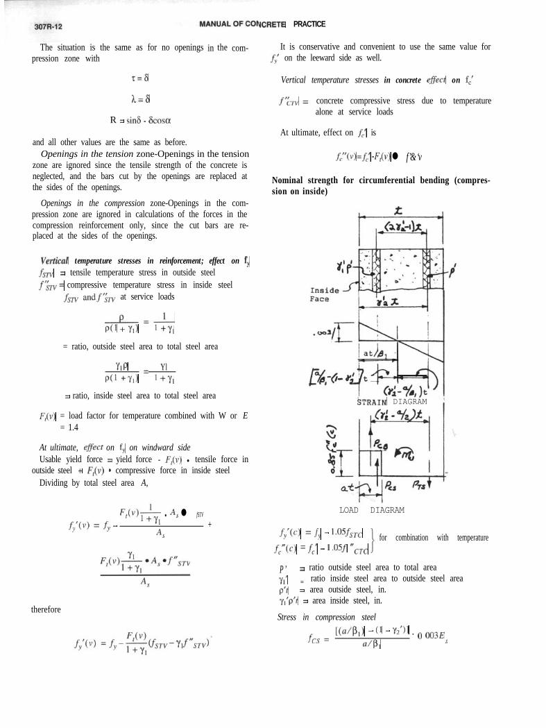
Nominal strength for circumferential bending (compres-sion on inside)
'STRAIN DIAGRAM
LOAD DIAGRAM
fy’(c) = fy - 1*05f,,, for combination with temperaturef,“(c) = f,’ - 1 .osf &C
P’ = ratio outside steel area to total area
Yl’ = ratio inside steel area to outside steel areap’t = area outside steel, in.yl’p’t = area inside steel, in.
Stress in compression steel
fcs =[(a/Pi) - (1 - Y2’)l . o 003E
4, s
REINFORCED CONCRETE CHIMNEYS COMMENTARY 307R-13
fcs =a-&(1-YJ
l O.O03E, Ify’(c) (A-1)a
Stress in tensile steel
fTs = Plk”-a- l O.O03E$ I f,'(c)
a(A-2)
Load in compression steel
PCS = fcs Yl’P’t
Load in tensile steel
(A-3)
pTS = fT&
Load in concrete compression block
PcB = O.Sf,“(c)ta
m,Pp,+P,-P,=o
(A-4)
(A-5)
(‘4-6)
Find the value of a that satisfies this equation.
MDs = @M,, 2 M,,
Note: For compression on outside
f;(c) =fy
fell(c) =fc
(A-7)
p = ratio of total area of vertical outside face reinforce-ment to total area of concrete chimney shell at sec-tion under consideration
y, = ratio of inside face vertical reinforcement area tooutside face vertical reinforcement area
= a& - 1 + y2Kd$
therefore ignore temperature. Eq. (A-3) becomes For c
PCS =fcs P’t
and Eq. (A-4) becomes
pTS =fTS %‘P’t
-C-U*r 1Ir-7I I I
in/in
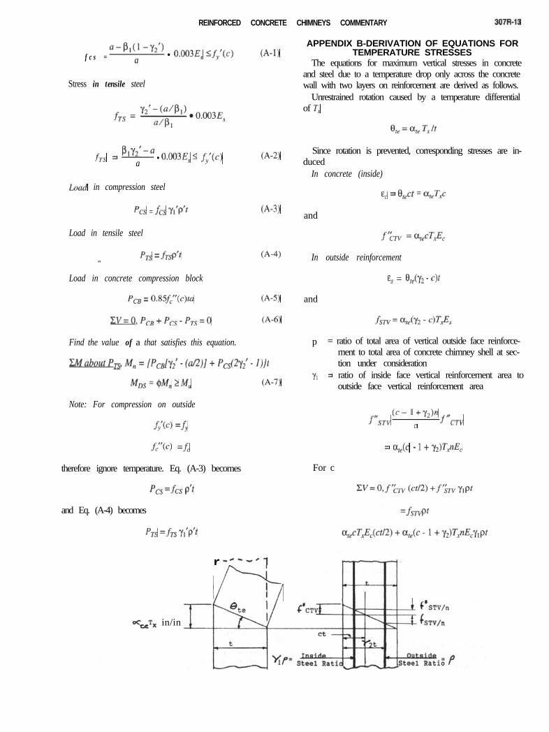
APPENDIX B-DERIVATION OF EQUATIONS FORTEMPERATURE STRESSES
The equations for maximum vertical stresses in concreteand steel due to a temperature drop only across the concretewall with two layers on reinforcement are derived as follows.
Unrestrained rotation caused by a temperature differentialof TX
Since rotation is prevented, corresponding stresses are in-duced
In concrete (inside)
E, = 8,ct = ateTg
and
In outside reinforcement
Es = %kY2 - c)t
and
f"ST"Cc- 1 +Y2)n
C f nCT”
307R-14 MANUAL OF CONCRETE PRACTICE
c2 + 2ny,pc+ 2ny,p(y2 - l)+ 2npc - 2npy2 =0
c2 + 2p7@1 + 1)~ + 2pnMy2 - 1) - y21 = 0
c2 + 2pdy1 + lk - 2PdY2 + YlU - y2N = 0
c = -pn(y, + 1) +
d[Pn(Y,+1)12+2Pn[Y2+Y,(l-Y2)l
The derivation for the equations for the maximum horizontalstresses in concrete and steel due to a temperature drop only,across the concrete wall with two layers of reinforcement, issimilar to that for the vertical temperature stresses
Replace p with p’Yl with yt’f%w with f’&c.fSTv with fSTCC with c’“12 with y2’
then
.f’&-c = ~,ec’TA
c'= -p'n(y,'+ l)+
i [p’n(y,‘+ U12+ 2P’~[Y,‘+Y~‘u -Y2’)1
APPENDIX C-REFERENCESC.l-Recommended references
American Concrete Institute307-69 Specification for the Design and Construction of
Reinforced Concrete Chimneys307-88 Standard Practice for the Design and Construc-
tion of Cast-in-Place Reinforced ConcreteChimneys
318 Building Code Requirements for StructuralConcrete
505-54 Standard Specification for the Design and Con-struction of Reinforced Concrete Chimneys
550R-93 Design Recommendations for Precast ConcreteStructures
American Society of Civil EngineersASCE 7-88 Minimum Design Loads for Buildings and
Other Structures (formerly ANSI A58.1)ASCE 7-95 Minimum Design Loads for Buildings and
Other Structures
American Concrete InstituteP.O. Box 9094Farmington Hills, Mich. 48333-9094
American Society of Civil Engineers1801 Alexander Bell DriveReston, Va. 20191
C.2-Cited references1 . PC1 Manual for Structural Design of Architectural Precast Concrete ,
Prestressed Concrete Institute, 1977.
2. PC1 Design Handbook-Precast and Ptestressed Concrete, Pre-stressed Concrete Institute, 3rd Edition, 1985.
3. Warnes, C. E., “Precast Concrete Connection Details for All SeismicZones,” Concrete International, V. 14, No. 11, Nov. 1992, pp. 36-44.
4. Simiu, E., and Scanlon, R. H., Wind E$ects on Structures, 2nd edition,John Wiley and Sons, 1986.
5. Hollister, S. C., “Engineering Interpretation of Weather BureauRecords for Wind Loading on Structures,” Wind Loads on Buildings andStructures, Building Science Series, No. 30, National Bureau of Standards,Washington, DC., 1969, pp. 1.51-164.
6. Vickery, B. J., “On the Reliability of Gust Loading Factors,” WindLoads on Buildings and Structures, Building Science Series, No. 30,National Bureau of Standards, Washington, D.C., 1969, pp. 93-104.
7. Vickery, B. J., and Basu, R. I., “Simplified Approaches to the Evalua-tion of the Across-Wind Response of Chimneys,” Journal of Wind Engi-neering and Industrial Aerodynamics, V. 14, Amsterdam, 1985, pp. 153-166.
8. Rumman, W. S., “Reinforced Concrete Chimneys,” Handbook ofConcrete Engineering, 2nd Edition, Mark Fintel, ed., Van Nostrand Rein-hold Co., New York, 1985, pp. 565-586.
9. Basu, R. I., “Across-Wind Responses of Slender Structures of CircularCross-Section to Atmospheric Turbulence,” PhD thesis, Faculty of Engi-neering Science, University of Western Ontario, London, Ontario, 1982.
10. Vickery, B. J., and Basu, R. I., “Response of Reinforced ConcreteC h i m n e y s t o V o r t e x S h e d d i n g , ” Engineer ing Structures , V . 6 , N o . 4 , Guild-ford, Oct. 1984, pp. 324-333.
11. Davenport, A. G., “Gust Loading Factors,” Proceedings, ASCE, V.93, ST3, June 1967, pp. 1 l-34.
12. Simiu, E.; Marshall, R. D.; and Haber, S., “Estimation of Along-Wind Building Response,” Proceedings, ASCE, V. 103, ST7, July 1977,pp. 1325-1338.
13. Vickery, B., “Across-Wind Loading on Reinforced Concrete Chim-neys of Circular Cross Section,” Boundary Layer Wind Tunnel Report,BLW’I-3-1993, University of Western Ontario, Dec. 1993.
14. Zdravkokvich, M. M., “Review of Flow Interference Effects betweenTwo Cylinders in Various Arrangements,” Journal of Fluids Engineering,v. 99, 1977, p. 618.
15. Vickery, B. J., and Daly, A., “Wind Tunnel Modelling as a Means ofPredicting the Response of Chimneys to Vortex Shedding,” EngineeringStructures, V. 6, No. 4, Guildford, Oct. 1984, pp. 363-368.
16. Ruscheweyh, H., “Problems with In-Line Stacks: Experience withFull-Scale Objects,” Engineering Structures, V. 6, No. 4, Guildford, Oct.1984, pp. 340-343.
17. Dryden, H. H., and Hill, G. C., “Wind Pressure on Circular Cylindersand Chimneys,” Research Paper No. 221, National Bureau of Standards,Washington, DC., 1930. Also, NBS Journal of Research, VY5, Sept. 1930.
18. ASCE Task Committee on Wind Forces, “Wind Forces on Struc-tures,” Transactions, ASCE, V. 126, Part II, 1961, pp. 1124-l 198.
19. Okamoto, T., and Yagita, M., “Experimental Investigation Flow Pasta Circular Cylinder of Finite Length Placed Normal to a Uniform Stream,”Bulletin, Japan Society of Mechanical Engineers (Tokyo), No. 16, 1973, p.805.
20. Task Committee on Steel Chimney Liners, Design and Constructionof Steel Chimney Liners, American Society of Civil Engineers, New York,1975,226 pp.
21. “NEHRP 1994 Recommended Provisions for the Development ofSeismic Regulations for New Buildings Prepared by the Building SeismicSafety Council.”
22. Mokrin, 2. A. R., and Rumman, W. S., “Ultimate Capacity of Rein-forced Concrete Members of Hollow Circular Sections Subjected to Mono-tonic and Cyclic Bending,” AC1 JOURNAL, Proceedings V. 82, No. 5, Sept-Oct. 1985, pp. 653-656.
23. Rumman, W. S., and Sun, R. T., “Ultimate Strength Design of Rein-forced Concrete Chimneys,” AC1 JOURNAL, Proceedings V. 74, No. 4, Apr.1977, pp. 179-184.
24. Hognestad, E., “Study of Combined Bending and Axial Load inReinforced Concrete Members,” Bulletin No. 399, Engineering Experi-ment Station, University of Illinois, Urbana, 1951, 128 pp.