Embed Size (px)
DESCRIPTION
mqnuql
Citation preview

Acid Gas Cleaning Demo
• • • • • • • • • • • • • • • • • • • • • • • • • • • • • • • • • • • • • • • • • • • • • • • • • • • • •
Working Instructions
Manya Garg, Product Management, Aspen Technology, Inc.
Acid Gas Cleaning is a new functionality available in Aspen HYSYS in versions V8.3 and later. To learn
more about the feature or to order the latest version, please visit the website on
www.aspentech.com/acidgascleaning.

Introduction:
This demo is a series of steps to demonstrate the workflow of using Acid Gas Cleaning in Aspen
HYSYS. Acid Gas Cleaning is a new functionality to model gas sweetening processes. It uses a
specialized property package backed by Aspen Properties and uses rate-based calculations to
give accurate and reliable results. This demo will only work on Aspen HYSYS versions 8.3 or
higher.
Problem Statement:
In this demo the user is supposed to be a process engineer who wants to set up quickly a
flowsheet for performing Acid Gas Cleaning. The Amine being used will be DGAmine.
Supporting files:
Absorber Complete.hsc
Makeup Starter File.hsc
Acid Gas Demo Final.hsc
Demo Instructions:
Part 1: use existing example case
Steps:
Open Aspen HYSYS. Go to AspenONE Exchange and search for ‘Acid Gas Cleaning using
DGAmine’ (can also use appropriate keywords, but pick this file). Pick the file and download it,
and open it in HYSYS. Demonstrate to the customer that this can serve as a great starting point
to enter their own feed conditions.
Part 2: set up Properties Environment
Problem: Set up the Properties Environment for Acid Gas removal of H2S and CO2 using
DGAmine. The Component list should include, but need not be limited to, Methane, Ethane,
Nitrogen. Note that you should be able to successfully step into the Simulation Environment,
but you do not need to do anything there. The steps to do this are given below.

Steps:
1. Start a new case in HYSYS by clicking on FileNew from the top toolbar
2. Add a new HYSYS component list
3. Add appropriate components in the list
4. Add a new HYSYS Fluid Package

5. The Property Package will automatically be selected as ‘Acid Gas’.
6. Enter the Simulation Environment.

Part 3: Add an Absorber
Problem: Set up one Absorber column along with suitable inlet and outlet streams using the
specifications and format provided. The steps are given below.
Steps:
1. From the Model and Streams Palette, select the Absorber Column and drag it on to the flowsheet
2. Double-click on the Absorber column to open its forms. On the Design|Connections page, enter information about the stream connections, stages and stage pressures.

Number of stages: 20
3. On the Parameters|Acid Gas page, enter information about the tray and column
geometry:

1 column section of Type Valve (Glitsch)
Diameter: 2.5 ft, Tray Spacing: 2 ft
Top Stage pressure: 207 psia, Bottom Stage pressure: 210 psia
4. For each of the input streams, double-click on the stream and open the form. Enter the information provided in blue on the Conditions and Composition pages.
Lean Amine:

Sour Gas:

5. From the column form, navigate to Performance|Acid Gas and demonstrate how easy it
is to see relevant results in desired units for Acid Gas Cleaning.
6. The file ‘Absorber Complete.hsc’ provides the solution until now.

Part 4: Add a Makeup Block
Open the provided ‘Makeup Starter File.hsc’. If the system asks if you want to keep the
flowsheet on Holding mode, say Yes.
Problem: in this situation, the client has already set up their entire flowsheet, along with the
regenerator and the recycle. However, the flowsheet will have problems converging (try to
solve in front of customer to see that program goes through a lot of operations and may not
even solve in the end). This is because there are amine and water losses in the system which
have not been accounted for. The user needs to add them somehow, and know exactly how
much to add. To solve this problem, we have a Makeup block unit operation. The following
steps show how to add the Makeup block.
Steps:
1. Break the connection between the stream ‘To Pump’ and ‘Lean/Rich Exchanger’ and add an outlet stream for the exchanger called ‘To Tank’. You can do this from the Heat Exchanger form by deleting ‘To Pump’ from the outlet and entering ‘To Tank’ there. this will create a new stream called ‘To Tank’.

2. From the Model and Streams Palette, add a Makeup unit operation under the ‘Common’ tab

3. Open the Makeup Block forms. Enter the Inlet stream as ‘To Tank’ and the Outlet stream as ‘To Pump’.
4. Enter the DGA composition as 40% and the flow rate as 100 USGPM.
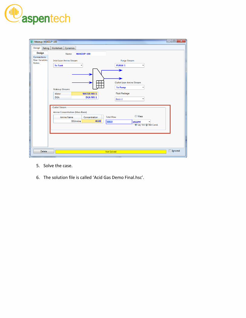
5. Solve the case.
6. The solution file is called ‘Acid Gas Demo Final.hsc’.