Embed Size (px)
Citation preview
i
ACKNOWLEDGEMENTS
The NJDEP’s Vapor Intrusion Guidance document was prepared by staff in the New Jersey
Department of Environmental Protection (NJDEP) Site Remediation and Waste Management
Program (SRWMP) and the Division of Science, Research and Technology (DSRT).
Primary Authors:
NJDEP Vapor Intrusion Committee
Diane Groth, Chair
John E. Boyer
Tracy Grabiak
William Hose
Stephen Myers
Paul Sanders
Heather Swartz
Contributing Author:
Kathleen Grimes (NJDEP)
Technical Reviewers outside the NJDEP:
Blayne Hartman (H&P Mobile GeoChemistry)
Ian Hers (Golder Associates)
Jennifer Hubbard (USEPA Region 3)
Todd McAlary (GeoSyntec Consultants)
Gina Plantz (Severn Trent Laboratories)
Henry Schuver (United States Environmental Protection Agency)
Site Remediation Industry Network
Technical Regulations Advisory Committee
Special thanks for the assistance of the following individuals:
Olga Boyko (NJDEP) Brian Crisafulli (NJDEP)
Linda Cullen (NJDEP) Jerald Fagliano (NJDHSS)
Barry Frasco (NJDEP) Greg Giles (NJDEP)
David Haymes (NJDEP) George Nicholas (NJDEP)
Kathy Pietras (NJDEP) Kevin Schick (NJDEP)
Jeff Story (NJDEP) Chad Van Sciver (NJDEP)

ii
DISCLAIMER
The use of any trade names, products or materials in this document does not constitute an
endorsement by the State of New Jersey’s Department of Environmental Protection.
The information in the NJDEP’s Vapor Intrusion Guidance document is provided free of charge
to the public. The State of New Jersey, its agencies and employees assume no responsibility to
any person or entity for the use of this information. There are no representations or warranties,
expressed or implied, of any kind with regard to this information, and any use of this information
is made at the risk of the user.
Neither the NJDEP nor the State of New Jersey maintains many of the web links and web
addresses in the NJDEP’s Vapor Intrusion Guidance. The NJDEP makes no special endorsement
for the content of these links, their sites or the views expressed by the sites’ publishers.
Web sites may change or remove their contents at any time. Therefore, the NJDEP cannot
guarantee that the material on the referenced Web sites will be the same as it was when the
Vapor Intrusion Guidance was developed or even that the links will be available.
Trademarks (e.g., Microsoft Works, Adobe Acrobat) belong to their respective companies.

iii
TABLE OF CONTENTS
ACKNOWLEDGEMENTS ............................................................................................................................................ i
DISCLAIMER .............................................................................................................................................................. ii
TABLE OF CONTENTS .............................................................................................................................................iii
ABBREVIATION LIST ............................................................................................................................................. viii
1.0 INTRODUCTION .......................................................................................................................................... 1
1.1 Regulatory Basis for the Guidance .................................................................................................. 1
1.2 Intended Use of the Guidance ......................................................................................................... 2
1.3 Overview of the Guidance ................................................................................................................ 3
1.4 Guidance Updates ............................................................................................................................ 5
2.0 CONCEPTUAL SITE MODEL ..................................................................................................................... 6
2.1 Sources of Vapor Intrusion.............................................................................................................. 8
2.2 Vapor Migration Mechanisms ......................................................................................................... 8
2.2.1 Diffusion of vapors from sources in the unsaturated zone .................................................. 9
2.2.2 Diffusion of vapors from sources in shallow ground water .............................................. 10
2.2.3 Advective/convective transport of vapors ......................................................................... 11
2.2.4 Vapor migration through preferential pathways .............................................................. 13
2.3 Receptors ........................................................................................................................................ 15
2.4 Factors Affecting Vapor Migration ............................................................................................... 15
2.4.1 Biodegradation ................................................................................................................. 16
2.4.2 Site Stratigraphy ............................................................................................................... 16
2.4.3 Soil Moisture and Ground Water Recharge ..................................................................... 18
2.4.4 Fluctuations in Water Table Elevation ............................................................................. 19
2.4.5 Ventilation Systems in Commercial/Industrial Buildings ................................................. 21
3.0 DECISION FRAMEWORK ......................................................................................................................... 24
3.1 Preliminary Assessment and Site Investigation ............................................................................ 24
3.2 Remedial Investigation ................................................................................................................... 27
3.3 Site-Specific Screening Options ..................................................................................................... 29
3.4 Remediation and Monitoring ......................................................................................................... 31
4.1 Introduction .................................................................................................................................... 32
4.2 Ground Water Screening Levels .................................................................................................... 32
4.2.1 Application of the Ground Water Screening Levels .......................................................... 33
4.2.2 Degradation of BTEX Chemicals...................................................................................... 35
4.3 Indoor Air Screening Levels .......................................................................................................... 35
4.3.1 Application of the Indoor Air Screening Levels ................................................................ 35
4.3.2 Alternate Indoor Air Screening Levels ............................................................................. 36
4.3.3 Rapid Action and Health Department Notification Levels ............................................... 37
4.4 Soil Gas Screening Levels .............................................................................................................. 38
iv
5.0 SITE-SPECIFIC SCREENING PROCEDURES ....................................................................................... 39
5.1 Default Screening Numbers for Alternate Soil Textures .............................................................. 39
5.2 Site-Specific Use of the J&E Model for Calculation of VI GWSL ............................................... 39
5.2.1 Chemical Properties ......................................................................................................... 40
5.2.2 Toxicological and Exposure Parameters .......................................................................... 40
5.2.3 Soil Texture ....................................................................................................................... 41
5.2.4 Soil Physical and Chemical Properties ............................................................................ 43
5.2.5 Building Parameters ......................................................................................................... 44
5.2.6 Depth to Ground Water .................................................................................................... 47
5.2.7 Summary of Site-Specific J&E Modeling for Calculation of GWSL for the VI
Pathway ............................................................................................................................ 47
5.3 Additional Site-Specific Options .................................................................................................... 48
6.0 SAMPLING PROCEDURES AND INVESTIGATION REQUIREMENTS ............................................. 50
6.1 Preparation of a Vapor Intrusion Workplan ................................................................................. 50
6.1.1 Conceptual Site Model ...................................................................................................... 50
6.1.2 General Issues .................................................................................................................. 51
6.1.3 Investigative Tools ............................................................................................................ 51
6.1.3.1 Ground Water Sampling ................................................................................. 52
6.1.3.2 Soil Gas Sampling ........................................................................................... 52
6.1.3.3 Indoor Air Sampling ....................................................................................... 55
6.1.3.4 Soil Sampling ................................................................................................. 57
6.1.4 Preferential Pathways ...................................................................................................... 57
6.1.5 VI Report Requirements .................................................................................................... 58
6.2 Ground Water Investigation and Sampling Procedures ............................................................... 59
6.2.1. Saturated Zone Features Affecting Vapor Intrusion ......................................................... 59
6.2.1.1 Clean Water Lens ............................................................................................ 59
6.2.1.2 Depth to Saturated Zone and Stratigraphy ..................................................... 61
6.2.1.3 Fluctuation in Depth to Saturated Zone.......................................................... 62
6.2.1.4 Complex Hydrogeologic Settings .................................................................... 62
6.2.1.5 Proximity to Preferential Pathways ................................................................ 63
6.2.1.6 Potential for Contaminant Degradation ......................................................... 63
6.2.2 Use of Pre-Existing Ground Water Data .......................................................................... 64
6.2.2.1 Interpolation of Nearby Data .......................................................................... 64
6.2.2.2 Use of Drinking Water Well Data ................................................................... 65
6.2.3 Obtaining New Ground Water Data to Evaluate the VI Pathway .................................... 65
6.2.3.1 Ground Water Sampling Location .................................................................. 66
6.2.3.2 Sampling Depth Intervals .............................................................................. 67
6.2.3.3 Direct Push and Alternative Ground Water Sampling Methods ..................... 69
6.2.3.4 Monitoring Well Sampling Methods for VI Investigations .............................. 70
6.2.3.5 Installation of New Monitor Wells .................................................................. 73
6.2.3.6 Ongoing Ground Water Monitoring ............................................................... 74
6.3 Exterior or Near Slab Soil Gas Sampling Procedures .................................................................. 75
6.3.1 Application ........................................................................................................................ 75
6.3.1.1 Stand-Alone assessment of the VI pathway (Near Slab Only)......................... 76
6.3.1.2 Field screening ............................................................................................... 77
6.3.1.3 Evaluating contaminant patterns .................................................................... 78
6.3.1.4 Assessing background contamination ............................................................. 78
6.3.2 Sampling Procedure ......................................................................................................... 78
6.3.2.1 Site Conditions ................................................................................................ 78
6.3.2.2 Soil Gas Sampling ........................................................................................... 79
6.3.2.3 Annular Seal and Tracer Gas ......................................................................... 80
6.3.2.4 Sample Containers and Analytical Methods ................................................... 81
6.3.2.5 Purge Volumes ................................................................................................ 84
6.3.2.6 Sample Flow Rate .......................................................................................... 84
v
6.3.2.7 Sample Locations ........................................................................................... 85
6.3.2.8 Number of Samples ......................................................................................... 85
6.3.2.9 Sample Frequency ........................................................................................... 86
6.3.2.10 Underground Utilities ..................................................................................... 86
6.3.2.11 License Requirements ..................................................................................... 87
6.3.2.12 Passive Sample Collection Methodologies ..................................................... 87
6.3.2.13 Undeveloped Parcels and Future Use ............................................................ 88
6.3.2.14 Data Evaluation .............................................................................................. 89
6.4 Sub-Slab Soil Gas Sampling Procedures ...................................................................................... 89
6.4.1 Application ........................................................................................................................ 90
6.4.1.1 Stand-Alone Assessment of the VI Pathway .................................................... 90
6.4.1.2 Evaluating Contaminant Patterns ................................................................... 91
6.4.1.3 Assessing Background Contamination ............................................................ 92
6.4.2 Sampling Procedure ......................................................................................................... 92
6.4.2.1 Permanent Sample Point Approach ................................................................ 93
6.4.2.2 Temporary Sample Point Approach ................................................................ 95
6.4.2.3 Sample Containers and Analytical Methods ................................................... 95
6.4.2.4 Sample Flow Rate ........................................................................................... 96
6.4.2.5 Calculating Purge Volumes ............................................................................ 97
6.4.2.6 Sample Location ............................................................................................. 97
6.4.2.7 Number of Sample Points ................................................................................ 97
6.4.2.8 Sample Frequency ........................................................................................... 98
6.4.3 Data Evaluation ................................................................................................................ 98
6.5 Conducting A Building Walkthrough and Survey ........................................................................ 99
6.5.1 Detection of Potential Background Sources ................................................................... 100
6.5.2 Recognition of Points of Vapor Intrusion in a Structure ................................................ 102
6.5.3 Identification of Possible Sample Locations ................................................................... 102
6.5.4 Education of the Occupants on Vapor Intrusion and Sampling Procedures .................. 103
6.6 Indoor Air Sampling Procedures ................................................................................................. 104
6.6.1 Application ...................................................................................................................... 105
6.6.1.1 Stand-Alone assessment of the vapor intrusion pathway ............................. 105
6.6.1.2 Evaluating contaminant patterns .................................................................. 105
6.6.1.3 Assessing background contamination ........................................................... 106
6.6.2 Sampling Procedures and Analytical Methods ............................................................... 106
6.6.2.1 TO-15 Requirements ..................................................................................... 107
6.6.2.2 TO-17 Requirements ..................................................................................... 108
6.6.2.3 Number of Sample Locations ....................................................................... 109
6.6.2.4 Sample Frequency ........................................................................................ 110
6.6.2.5 Pressure and Temperature Issues ................................................................ 110
6.6.3 Data Evaluation .............................................................................................................. 111
7.0 EVALUATION OF ANALYTICAL RESULTS ........................................................................................ 112
7.1 Background Sources .................................................................................................................... 112
7.2 Ground Water Samples ................................................................................................................ 112
7.3 Vertical Ground Water Contaminant Profile .............................................................................. 113
7.4 Sub-Slab Soil Gas Samples .......................................................................................................... 114
7.5 Indoor Air Samples from the Basement ...................................................................................... 115
7.6 Multiple Indoor Air Samples from Different Floors ................................................................... 116
7.7 Indoor Air and Sub-Slab Soil Gas Samples ................................................................................ 117
7.8 Indoor Air Data Evaluation ......................................................................................................... 120
7.9 Official Notification ..................................................................................................................... 121
8.0 BACKGROUND CONTAMINATION ...................................................................................................... 123
8.1 Background Investigations .......................................................................................................... 123

vi
8.2 Background Indoor Air Sources .................................................................................................. 124
8.3 Methods to Address Background Sources ................................................................................... 126
8.3.1 Primary Factors.............................................................................................................. 126
8.3.1.1 Site-Specific Contaminants of Concern ........................................................ 126
8.3.1.2 Sub-slab soil gas sampling ............................................................................ 127
8.3.1.3 Ambient (outdoor) air sampling .................................................................... 128
8.3.2 Secondary Factors .......................................................................................................... 128
8.3.2.1 Building survey ............................................................................................. 128
8.3.2.2 Indoor air background databases ................................................................. 129
8.3.2.3 Exterior soil gas sampling ............................................................................ 130
8.3.3 Other Issues .................................................................................................................... 130
9.0 PETROLEUM HYDROCARBONS ........................................................................................................... 132
9.1 Introduction .................................................................................................................................. 132
9.2 Biodegradation ............................................................................................................................. 133
9.3 Site Evaluation ............................................................................................................................. 134
10.0 REMEDIAL ACTION ............................................................................................................................... 135
10.1 Remedial Action Techniques ....................................................................................................... 135
10.1.1 Subsurface Depressurization Systems: ........................................................................... 136
10.2 Remedial Action Implementation ................................................................................................ 137
10.2.1 Remedial Action System Requirements ........................................................................... 137
10.2.2 Qualifications ................................................................................................................. 138
10.2.3 Permits ............................................................................................................................ 138
10.2.4 Pre-Construction Considerations ................................................................................... 139
10.3 Remedial Action Operation, Monitoring and Maintenance ....................................................... 140
10.3.1 Institutional and Engineering Controls .......................................................................... 140
10.3.2 Remedial Action System Verification Sampling, Monitoring and Maintenance ............. 141
10.3.2.1 Verification Procedures ................................................................................ 141
10.3.2.2 Monitoring and Maintenance........................................................................ 142
10.3.2.3 Remedial Action Progress Report Submission .............................................. 143
10.3.2.4 System Termination Sampling ....................................................................... 143
11.0 COMMUNITY OUTREACH FOR VAPOR INTRUSION SITES ........................................................... 148
11.1 About the Office of Community Relations .................................................................................. 148
11.2 Why Do Community Outreach? .................................................................................................. 148
11.3 Communicating with the Public about Vapor Intrusion ............................................................ 149
11.3.1 Local Officials ................................................................................................................ 149
11.3.2 General Public ................................................................................................................ 149
11.3.3 Media .............................................................................................................................. 150
11.4 Arranging Sample Appointments ................................................................................................ 150
11.4.1 Letters ............................................................................................................................. 151
11.4.2 Phone Calls ..................................................................................................................... 152
11.5 Collecting Samples ....................................................................................................................... 153
11.6 Reporting Sample Results ............................................................................................................ 153
11.6.1 Verbal Reports ................................................................................................................ 154
11.6.2 Written Reports ............................................................................................................... 154
11.7 Community Outreach during Remedial Actions ......................................................................... 156
11.8 Meeting with the Public ............................................................................................................... 156
11.9 Additional Information ................................................................................................................ 158
REFERENCES ........................................................................................................................................................... 159
vii
TABLES
Table 1 - NJDEP Master Table (Generic Vapor Intrusion Screening Levels)
Table 2 - NJDEP Rapid Action and Health Department Notification Levels
Table 3 - Ground Water Screening Levels for Alternate Soil Textures
APPENDIX A Decision Flow Chart
APPENDIX B Indoor Air Building Survey and Sampling Form
APPENDIX C Instructions for Occupants - Indoor Air Sampling Events (English and Spanish)
APPENDIX D Evaluating Indoor Air Near VOC Contaminated Site fact sheet
APPENDIX E Subsurface Depressurization Systems fact sheet
APPENDIX F Background Volatile Levels in Homes: Literature Review
APPENDIX G Derivation of the Generic Screening Levels
APPENDIX H Common Household Sources of Background Indoor Air Contamination
APPENDIX I Quality Assurance Requirements
viii
ABBREVIATION LIST
ATSDR Agency for Toxic Substances and Disease Registry
BAQE Bureau of Air Quality Evaluation
BFB 4-bromofluorobenzene
BTEX benzene, toluene, ethylbenzene and xylenes
bwt below the water table
cc cubic centimeter
CHC chlorinated hydrocarbon
CPSi cancer potency slope, inhalation
CRM certified reference material
CSM conceptual site model
DDE dichlorodiphenyldichloroethylene
DNAPL dense non-aqueous phase liquid
DSRT Division of Science Research and Technology (NJDEP)
EDSA Electronic Data Submission Application
FID flame ionization detector
FSPM Field Sampling Procedures Manual
FTDS field test data sheets (for Analytical Methods TO-15 and TO-17)
GC gas chromatography
GC/MS gas chromatography/mass spectrometry
GIS Geological Information System
GWSL Ground Water Screening Level
GWQS Ground Water Quality Standards
HDNL Health Department Notification Level
Hg mercury
HQ hazard quotient
HVAC heating, ventilation and air conditioning
IA indoor air
IASL Indoor Air Screening Level
ix
ID inner diameter
IEC immediate environmental concern
IRIS Integrated Risk Information System
IRM interim remedial measure
ITRC Interstate Technology and Regulatory Council
J&E Johnson and Ettinger model
Koc organic carbon partition coefficient
LCS laboratory control samples
LFPS low-flow purging and sampling
LNAPL light non-aqueous phase liquid
MDL method detection limit
MIBK 4-methyl-2-pentanone
MW monitor well
μg/m3 microgram per cubic meter
MTBE methyl tertiary-butyl ether
NAPL non-aqueous phase liquid
NELAP National Environmental Laboratory Accreditation Program
N.J.A.C. New Jersey Administrative Code
NJDHSS New Jersey Department of Health and Senior Services
NJDEP New Jersey Department of Environmental Protection
OD outer diameter
OQA Office of Quality Assurance (NJDEP)
OSHA Occupational Safety and Health Administration
PA DEP Pennsylvania Department of Environmental Protection
PA/SI Preliminary Assessment and Site Investigation
ppbv parts per billion by volume
PCE tetrachloroethene (also called perchloroethene)
PDBS passive diffusion bag samplers
PEL permissible exposure limit
PID photoionization detector
QA/QC quality assurance/quality control
x
RAL Rapid Action Level
RAW Remedial Action Workplan
RBC risk based concentration
RfC reference concentration
RfD reference dose
RfDi reference dose, inhalation
RL reporting limits
RRT relative retention time
SCAN continuous scanning mode
SDG sample delivery group
SGSL Soil Gas Screening Level
SIM selective ion monitoring
SOP Standard Operating Procedures
SRM standard reference material
SSURGO Soil Survey Geographic Database
SSV safe sampling volume
TBA tertiary butyl alcohol
TCE trichloroethene
TRSR Technical Requirements for Site Remediation (N.J.A.C. 7:26E)
URF unit risk factor
USDA United States Department of Agriculture
USEPA United States Environmental Protection Agency
USGS United States Geological Survey
VI vapor intrusion
VOC volatile organic compound(s)

NJDEP Vapor Intrusion Guidance
October 2005
1
1.0 INTRODUCTION
Vapor intrusion (VI) has received increased attention and evolved rapidly over the last few years
as a potential exposure pathway of concern in the investigation and remediation of contaminated
sites. VI is defined as the migration of volatile chemicals from the subsurface into overlying
buildings (USEPA 2002b). The presence of volatile organic compounds (VOC) in soil or ground
water offers the potential for chemical vapors to migrate through subsurface soils and along
preferential pathways (such as underground utility lines) potentially impacting the indoor air
quality of affected buildings.
The accumulation of volatile vapors in impacted structures can result in more immediate health
concerns associated with high levels of contaminants, as well as the potential for chronic (i.e.,
long term) health effects associated with lower levels of site related contaminants. This
document addresses both chronic effects and more immediate health concerns.
The objective of the NJDEP document is to provide guidance in determining whether VI of site
related contaminants is occurring and to highlight what actions are appropriate. This document
replaces the New Jersey Department of Environmental Protection’s Indoor Air Sampling Guide
for Volatile Organic Compounds (NJDEP 1999).
1.1 Regulatory Basis for the Guidance
The regulatory basis for the evaluation of the VI pathway is rooted in various sections of the
Department’s Technical Requirements for Site Remediation (NJDEP 2003a), or TRSR. The
TRSR (N.J.A.C. 7:26E-1.11) state that the first priority during remediation is to ensure that
“contaminants in all media should be contained and/or stabilized to prevent contaminant
exposure to receptors and to prevent further movement of contaminants through any pathway.”
N.J.A.C. 7:26E-1.13 sets forth narrative ground water remediation standards for contaminated
sites which “Ensure no release of contaminants to the ground surface, structures or air in
concentrations that pose a threat to human health.”
NJDEP Vapor Intrusion Guidance
October 2005
2
Many of the other narrative ground water remediation standards in N.J.A.C. 7:26E-1.13 are also
relevant to the VI pathway, including the policies and narrative criteria from the Ground Water
Quality Standards (GWQS), in N.J.A.C. 7:9-1.2 and 1.7. These requirements incorporate human
health and welfare concerns specified in the November 13, 1991 Basis and Background for the
GWQS.
In addition to the above, the TRSR at N.J.A.C. 7:26E-3.5 stipulate that “the site investigation of
building interiors shall be conducted when contaminants . . . outside the building have the
potential to migrate into the building.” The TRSR at N.J.A.C. 7:26E-4.1 also state that the
purpose of a remedial investigation is to “identify the migration paths and actual or potential
receptors of contaminants on or through air, soil, bedrock, sediment, ground water, surface water
and structures at a contaminated site.”
Furthermore, N.J.A.C. 7:26E-4.4(h)3viii specifies that the occurrence of ground water
contamination above the applicable remediation standards must include evaluation of “any
subsurface utilities, basements or other structures to determine whether vapor hazards as a result
of the ground water contamination may exist for receptors associated with the utility or
structure.” The TRSR at N.J.A.C. 7:26E-6.3(d)7 also stipulate that the submission of a
proposal for natural ground water remediation must demonstrate that “contaminant levels in
ground water do not present a vapor risk to any receptors.”
1.2 Intended Use of the Guidance
The NJDEP guidance is intended for use in the evaluation of the VI pathway at primarily VOC
contaminated sites located within the state of New Jersey. While this document concentrates on
VOC contaminated sites, the Department may investigate other volatile compounds for the VI
pathway on a case by case basis. The potential for VI impacts shall be evaluated if volatile
contaminated media are present at a site. In addition, this evaluation shall be considered for sites
where active ground water and/or soil remediation systems are proposed or being undertaken that
may affect soil vapor concentrations and the generation of potentially volatile/toxic degradation
products with the potential to impact the air quality of nearby structures. These systems include,
but are not limited to, air sparging, bioremediation, bioventing and chemical oxidation systems.
NJDEP Vapor Intrusion Guidance
October 2005
3
The intended use of this document is to assist interested parties in determining whether VI
impacts may be present that require additional actions to mitigate or eliminate actual or potential
human health impacts. This guidance addresses those procedures currently recommended by the
New Jersey Department of Environmental Protection (NJDEP or the Department) in the
evaluation of potential VI related impacts at a site. While this document is guidance, not
regulation, evaluation and remediation for the VI pathway is required as part of the TRSR (as
previously discussed). It is therefore recommended that the regulated community consult with
the Department before implementing methodologies/procedures not included in this document.
1.3 Overview of the Guidance
This guidance incorporates a risk based, staged approach to evaluate the potential for VI at sites
under review. The document has been developed after consideration of the latest, state of the
science procedures/methodologies currently included in USEPA and other State guidance, as
well as information available from conferences and training events, that address the VI pathway.
While the Department has incorporated many of the latest recommended methodologies in the
document, New Jersey specific characteristics, input parameters and policies have also been
included, where applicable.
The Department’s investigative strategy for the VI pathway consists of a series of stages
designed to consistently and logically progress through the process of assessing the potential for
VI. These stages are structured to be consistent with the organization of a typical investigation
as required in the TRSR. Further detail on these stages can be found throughout this document.
In addition, the Decision Flow Chart (Appendix A) should be consulted when assessing the VI
pathway.
Chapter 2 provides a detailed introduction to concepts relevant to the VI pathway and guidance
on developing a conceptual site model (CSM).

NJDEP Vapor Intrusion Guidance
October 2005
4
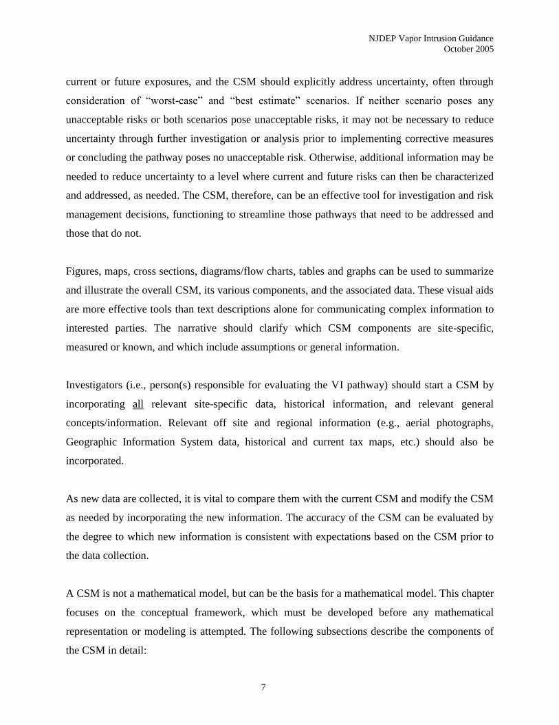
Chapter 3 describes the
general decision
framework for the
phased approach the
Department has defined
for the evaluation of a
site. The Preliminary
Assessment and Site
Investigation phase
presents a series of
situations where prompt
action is necessary in
order to address potential
impacts to public health.
The Remedial
Investigation phase deals
with strategies for
investigating and assessing the VI pathway. Site-specific screening options and procedures are
included in this phase. Finally, the Remediation and Monitoring phase addresses remedial
actions, monitoring and maintenance at the site.
The generic screening levels and their application are discussed in Chapter 4. Chapter 5 covers
the site-specific screening options available for use in the evaluation of a site. Recommended
investigative procedures for ground water, soil gas and/or indoor air are presented in Chapter 6.
Chapter 7 discusses the evaluation of analytical data collected to address the pathway.
Consideration of background ambient air and indoor air quality in the evaluation of a site is
discussed in Chapter 8. Chapter 9 includes current guidance on addressing sites contaminated
with petroleum hydrocarbons. Remedial alternatives along with monitoring and institutional
control requirements are covered in Chapter 10. Chapter 11 contains guidance on community
outreach when evaluating potential VI impacted sites. The tables and appendices included in the
VI Pathway Investigative Strategy
Preliminary Assessment and Site Investigation
Stage 1 Assess potential for vapor intrusion
Stage 2 Rapid Action Determination
Stage 3 Evaluate existing data against screening levels
Remedial Investigation
Stage 4 Develop and implement VI Investigation Workplan
4A. Delineate GW contamination
4B. Investigate soil gas
4C. Conduct sub-slab and indoor air sampling
Stage 5 Evaluate RI data using generic screening levels
Stage 6 Prepare and implement site-specific investigation
Stage 7 Evaluate data using generic or site-specific
screening levels
Remediation and Monitoring
Stage 8 Determine appropriate remedial action
Stage 9 Implement remedial action
Stage 10 Establish a long-term monitoring program
Stage 11 Assess ability to terminate remedial action
NJDEP Vapor Intrusion Guidance
October 2005
5
guidance are listed in the Table of Contents and provide detailed information in support of the
various topics included in the document.
1.4 Guidance Updates
As previously noted, evaluation of the VI pathway is a rapidly evolving field. With this
knowledge, the Department will update the document as the state of the science advances. The
Department intends to modify the screening level tables twice a year based on updates to the
USEPA Region III Risk Based Concentration (RBC) Table used in the development of the
screening levels. The Department will also modify the guidance as appropriate based on
advances in the recommended methodologies, analytical procedures and associated analytical
reporting limits.
The current document along with updates to the screening levels and other sections of the
document are, or will be, presented on the Department’s web site at
www.state.nj.us/dep/srp/guidance/vaporintrusion/. It is recommended that interested parties refer
to the NJDEP web site to ensure that they are using the most current information in the
evaluation of a site.
NJDEP Vapor Intrusion Guidance
October 2005
6
2.0 CONCEPTUAL SITE MODEL
Assessing the potential for VI to indoor air should begin with visualizing a simplified version of
the site or physical setting; this simplified idea, picture, or description is a conceptual site model
(CSM). This chapter serves as a guide for developing a CSM and also as a detailed introduction
to the VI pathway. Although not required, NJDEP strongly recommends early development of a
written, illustrated CSM that can be used to plan, scope, and communicate the next steps in the
investigation and any remedial actions, if needed. Starting an investigation in the absence of a
CSM is likely to increase costs and decrease efficiency. The CSM should be updated and refined,
as new data become available.
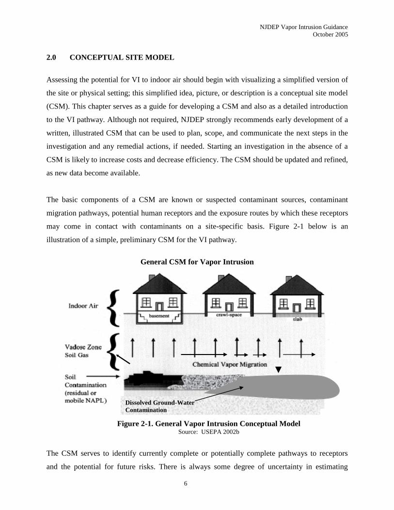
The basic components of a CSM are known or suspected contaminant sources, contaminant
migration pathways, potential human receptors and the exposure routes by which these receptors
may come in contact with contaminants on a site-specific basis. Figure 2-1 below is an
illustration of a simple, preliminary CSM for the VI pathway.
General CSM for Vapor Intrusion
Figure 2-1. General Vapor Intrusion Conceptual Model Source: USEPA 2002b
The CSM serves to identify currently complete or potentially complete pathways to receptors
and the potential for future risks. There is always some degree of uncertainty in estimating
Dissolved Ground-Water
Contamination
NJDEP Vapor Intrusion Guidance
October 2005
7
current or future exposures, and the CSM should explicitly address uncertainty, often through
consideration of “worst-case” and “best estimate” scenarios. If neither scenario poses any
unacceptable risks or both scenarios pose unacceptable risks, it may not be necessary to reduce
uncertainty through further investigation or analysis prior to implementing corrective measures
or concluding the pathway poses no unacceptable risk. Otherwise, additional information may be
needed to reduce uncertainty to a level where current and future risks can then be characterized
and addressed, as needed. The CSM, therefore, can be an effective tool for investigation and risk
management decisions, functioning to streamline those pathways that need to be addressed and
those that do not.
Figures, maps, cross sections, diagrams/flow charts, tables and graphs can be used to summarize
and illustrate the overall CSM, its various components, and the associated data. These visual aids
are more effective tools than text descriptions alone for communicating complex information to
interested parties. The narrative should clarify which CSM components are site-specific,
measured or known, and which include assumptions or general information.
Investigators (i.e., person(s) responsible for evaluating the VI pathway) should start a CSM by
incorporating all relevant site-specific data, historical information, and relevant general
concepts/information. Relevant off site and regional information (e.g., aerial photographs,
Geographic Information System data, historical and current tax maps, etc.) should also be
incorporated.
As new data are collected, it is vital to compare them with the current CSM and modify the CSM
as needed by incorporating the new information. The accuracy of the CSM can be evaluated by
the degree to which new information is consistent with expectations based on the CSM prior to
the data collection.
A CSM is not a mathematical model, but can be the basis for a mathematical model. This chapter
focuses on the conceptual framework, which must be developed before any mathematical
representation or modeling is attempted. The following subsections describe the components of
the CSM in detail:
NJDEP Vapor Intrusion Guidance
October 2005
8
• Sources of VI
• Vapor Migration Mechanisms
• Receptors and
• Factors Affecting Vapor Migration.
2.1 Sources of Vapor Intrusion
Initial consideration in the preparation of a CSM should be centered on whether there is a vapor
source with the potential to cause VI. In general, a vapor source of VI can be defined as the
presence, or reasonably suspected presence, of a chemical of sufficient volatility and toxicity in
the subsurface with sufficient mass and/or concentrations to pose a possible inhalation risk
within current or future occupied overlying enclosures. This definition includes the presence of a
volatile chemical or chemicals adsorbed to, or in the pore space/fractures of unsaturated soil or
rock, or in the uppermost portions of the saturated zone. Such vapor sources can exist in the form
of: free phase or residual NAPL above or near the top of the saturated zone; contaminated soil in
the vadose zone; and shallow dissolved phase contamination in ground water. Another possible
source of subsurface VI is the release of volatile compounds in the vapor phase from
underground tanks or piping and certain types of aboveground facilities that use volatile
compounds during operations. This particular source is commonly referred to as a “vapor cloud.”
Sources of indoor air contamination not associated with VI (e.g., ambient air, building materials,
consumer products) should also be considered when developing and evaluating a CSM.
2.2 Vapor Migration Mechanisms
When a chemical of sufficient volatility and toxicity is present in the subsurface, there are
several transport mechanisms by which the chemicals can migrate. The CSM should identify the
major and minor migration pathways and processes through which a receptor can be exposed at a
particular site. The four main transport mechanisms that should be considered are described and
illustrated below.

NJDEP Vapor Intrusion Guidance
October 2005
9
• Diffusion of vapors from sources in the unsaturated zone
• Diffusion of vapors from sources in shallow ground water
• Advective/convective transport of vapors
• Vapor migration through preferential pathways
2.2.1 Diffusion of vapors from sources in the unsaturated zone
Diffusion occurs as a result of a concentration gradient between the source and the surrounding
area; it can result in the upward, lateral or downward migration of vapors through the vadose
zone. The location of the source is an important factor influencing the direction of vapor
migration. Identifying soil gas concentration gradients may help determine the location of
unidentified vapor sources. Figure 2-2 illustrates lateral and downward vapor migration in the
Vapor Diffusion
Figure 2-2. Vapor Diffusion from Release at Surface Source: McAlary 2003
NJDEP Vapor Intrusion Guidance
October 2005
10
unsaturated zone from a release of contaminants near the surface The USEPA Draft Vapor
Intrusion Guidance (USEPA 2002b) recommends 100 feet as an initial estimate for steady state
travel distance based on diffusive vapor transport in the vadose zone. Variability in site
characteristics, such as soil porosity, effective permeability, ground surface cover, ambient
temperature and age of a release may increase or decrease the distance vapors migrate. A
relatively impermeable surface cover above a vapor source for example, may increase the
distance a vapor plume would travel laterally if it significantly impedes vapors from escaping to
the atmosphere.
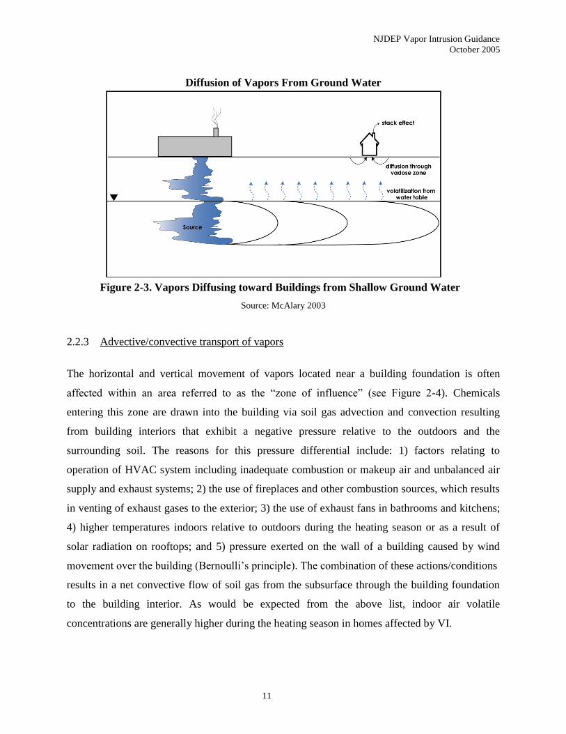
2.2.2 Diffusion of vapors from sources in shallow ground water
Diffusion occurs as a result of a concentration gradient between the source and the surrounding
area; in this case, the source is shallow groundwater contamination and/or NAPL. This can result
in the upward or lateral migration of vapors through the vadose zone. Figure 2-3 illustrates
diffusion of vapors in the vadose zone from shallow ground water contamination. Depending on
the hydraulic conductivity, hydraulic gradient, aquifer heterogeneity, time since chemicals were
released and natural attenuation processes, the distribution of volatile chemicals in ground water
may extend considerable distances.
Within a set volumetric space where contaminated ground water is the only source of vapors in
the subsurface, the total mass of volatiles off-gassing from ground water and diffusing through
the vadose zone (vertical mass flux) cannot exceed the total mass of volatiles moving through
that space laterally in ground water. For aquifers with slower ground water velocity, the lateral
mass flux in shallow ground water leaving the source area may be the limiting factor in VI
impacts.
NJDEP Vapor Intrusion Guidance
October 2005
11
Diffusion of Vapors From Ground Water
Figure 2-3. Vapors Diffusing toward Buildings from Shallow Ground Water
Source: McAlary 2003
2.2.3 Advective/convective transport of vapors
The horizontal and vertical movement of vapors located near a building foundation is often
affected within an area referred to as the “zone of influence” (see Figure 2-4). Chemicals
entering this zone are drawn into the building via soil gas advection and convection resulting
from building interiors that exhibit a negative pressure relative to the outdoors and the
surrounding soil. The reasons for this pressure differential include: 1) factors relating to
operation of HVAC system including inadequate combustion or makeup air and unbalanced air
supply and exhaust systems; 2) the use of fireplaces and other combustion sources, which results
in venting of exhaust gases to the exterior; 3) the use of exhaust fans in bathrooms and kitchens;
4) higher temperatures indoors relative to outdoors during the heating season or as a result of
solar radiation on rooftops; and 5) pressure exerted on the wall of a building caused by wind
movement over the building (Bernoulli’s principle). The combination of these actions/conditions
results in a net convective flow of soil gas from the subsurface through the building foundation
to the building interior. As would be expected from the above list, indoor air volatile
concentrations are generally higher during the heating season in homes affected by VI.

NJDEP Vapor Intrusion Guidance
October 2005
12
Advective/Convective Transport of Vapors
Figure 2-4. Advective and Convective Transport Near Buildings
Source: USEPA 2004d
Figure 2-4 illustrates the transport of vapors near a typical residence or building with a basement.
The rate of contaminant entry through the foundation and the air exchange rate of the building
will determine the concentration of the contaminants in the home resulting from VI. A similar
pattern of soil gas movement can occur around buildings without a basement or around those
without any concrete foundation slab. The term Qsoil in Figure 2-4 represents the rate of soil gas
entry into the building. In many cases, granular fill materials are placed beneath concrete slabs or
adjacent to building footings, which may be much more permeable to air flow than surrounding
soils. Air flow will occur through the path of least resistance, so the streamlines for air flow may
be different than those depicted on Figure 2-4.
NJDEP Vapor Intrusion Guidance
October 2005
13
Advective/convective transport of vapors can occur in other scenarios. It has been observed that
certain commercial and business operations may result in volatile organic vapors entering the
unsaturated zone solely as a vapor possibly due to density differences between these vapors and
the atmosphere (USEPA 2002b; Hartman 1998). These operations could include
tetrachloroethene (PCE) dry cleaning units, vapor degreasers in machine shops, spray booths in
inking or painting facilities using chlorinated solvent based inks or paints, and
USTs/underground piping. Highly permeable deposits and very high vapor concentrations are
necessary for there to be significant density dependent transport below ground, therefore this
scenario is likely to be relatively rare. Contaminated soil vapor may also occasionally result from
pressurized buildings forcing contaminated indoor air out through openings in the foundation and
into nearby soil. The affected area or zone of influence would likely be relatively small, but
could affect sub-slab or other soil gas samples collected below buildings or structures such as
those described above.
Another possible advective vapor transport mechanism, called “barometric pumping,” is caused
by cyclic changes in atmospheric pressure. These changes create a “piston like” force on soil gas,
possibly causing a cyclic up and down flow of contaminant vapors in the affected interval. The
magnitude of a barometric pressure cycle is typically a small percentage of atmospheric pressure
and its effect decreases with depth. The soil texture, soil air permeability, and moisture content
affect the depth to which the pressure change may affect vapor transport. Soil gas compression
and expansion in response to barometric pressure fluctuations may alternately enhance or inhibit
VI.
In areas subject to tidal fluctuation in the water table, or rapid increases in the water table
elevation due to stormwater runoff, such increases in water table elevation may enhance
advective transport.
2.2.4 Vapor migration through preferential pathways
NJDEP Vapor Intrusion Guidance
October 2005
14
In preparation of each CSM, investigators may look for the presence and locations of natural and
man made pathways in the subsurface with high gas permeability through which vapors can
rapidly migrate. The term preferential exposure pathway has been defined, in part, as:
“…a natural (e.g., shallow rock or vertically fractured soil) or manmade (e.g., buried
utilities) feature that creates a sufficiently direct pathway from a source to a receptor to
make the use of the default model [the Johnson and Ettinger model] for predicting indoor
air concentrations unacceptable. Shallow utilities buried at a depth that is insignificant
with respect to the column of soil between the slab and the source do not automatically
constitute a preferential pathway, nor should this definition include surface paving
outside the building or the presence of crushed stone beneath the slab as normally placed
for slab foundation material.” (PA DEP 2004)
Naturally occurring fractures and macropores may facilitate vertical or horizontal vapor
migration while anthropogenic features such as utility conduits would likely facilitate horizontal
vapor migration due to their shallow depth (USEPA 2002b). Buildings that are, or may become,
inhabited should be evaluated if they are associated with a preferential pathway that is within
some reasonable distance of a source area (based on professional judgment).
Investigators should also evaluate the potential for VI in situations where a preferential pathway
leading to a structure runs near to, or through, a source area. For sources containing aerobically
degradable contaminants, however, it is unlikely that sufficient vapors will reach the structure to
result in a VI problem unless the pathway and structure are both very close to the vapor source.
Biodegradation of benzene, toluene, ethylbenzene, and xylene (BTEX) vapors in the vadose zone
has been shown to be a very efficient process as long as sufficient oxygen is available (DeVaull,
et.al. 1997). Thus, if a preferential pathway is not close to a source area, biodegradable vapors
would likely degrade before reaching the pathway and/or within the pathway before reaching the
structure.
NJDEP Vapor Intrusion Guidance
October 2005
15
2.3 Receptors
The Technical Requirements for Site Remediation (NJDEP 2003a) define a receptor as “any
human or other ecological component which is or may be affected by a contaminant from a
contaminated site.” The primary VI receptors are the human occupants of enclosed spaces
overlying subsurface volatile contamination. Exposure to volatiles can result in health problems
in individuals occupying a building subject to VI. Enclosed spaces or buildings, for the purpose
of this guidance, are defined as any structure currently or potentially impacted by subsurface
volatile contaminants. To account for possible change in future use, VI is of potential concern in
buildings/enclosed spaces whether or not they are currently occupied. Buildings with significant
air exchange rates (e.g., commercial garages/spaces with large doors/openings) or significantly
limited use (e.g., small utility sheds) will be evaluated on a site-specific basis.
Human exposure typically can take place under a residential (unrestricted use) or nonresidential
(restricted use) exposure scenario. Residential settings include single family homes, townhouses,
and apartment buildings. Receptors under a residential exposure scenario consist of both adults
and children who are expected to spend a greater period of time in a residential setting than
those individuals in a nonresidential setting. As discussed in Chapter 4, it is the Department’s
policy that day care centers and schools are evaluated as a residential use due to the potentially
sensitive nature of the exposed population (children).
Nonresidential settings include office buildings and commercial or industrial complexes.
Nonresidential receptors consist of adult workers in the above buildings or complexes.
Nonresidential settings with sensitive populations (e.g., working pregnant women) will be
handled on a site-specific basis. Occupational settings that fall under the purview of OSHA may
be handled differently than those not subject to OSHA regulations when indoor air
concentrations from normal operating practices can not be ruled out.
2.4 Factors Affecting Vapor Migration
Vapor and liquid transport processes and their interactions with various geologic and physical
site settings (building construction and design) under given meteorological conditions have
NJDEP Vapor Intrusion Guidance
October 2005
16
unique effects on the VI pathway. Variations in building design, construction, use, and
maintenance, site-specific stratigraphy, sub-slab composition and temporal variation in
atmospheric pressure, temperature, precipitation, infiltration, soil moisture, water table elevation,
and other factors, combine to create a complex and dynamic system. General aspects of several
of these processes and site settings/conditions are described and illustrated below. These factors
are not listed in a prioritized manner and not all factors are relevant at every site:
• Biodegradation (of volatile contaminants as they migrate in the vadose zone)
• Site Stratigraphy
• Soil Moisture and Ground Water Recharge
• Fluctuations in Water Table Elevation
• Ventilation Systems in Commercial/Industrial Buildings.
2.4.1 Biodegradation
Many volatile contaminants, especially nonchlorinated hydrocarbons, can be degraded by
indigenous soil microbes in the presence of oxygen. Oxygen is ubiquitous in the atmosphere, at a
concentration of about 21%, which constitutes an essentially limitless supply. Oxygen is
transported to the subsurface by barometric pumping, and by diffusion if there is a concentration
gradient, which will develop at sites where oxygen is being consumed in the subsurface at
appreciable rates. In some cases, oxygen is consumed at rates faster than it migrates downward,
so degradation rates vary significantly from site to site (Roggemans et al. 2001).
2.4.2 Site Stratigraphy
Figure 2-5 illustrates a hypothetical example of how determining site stratigraphy can be crucial
to discovering actual or potential vapor migration pathways. Figure 2-5 depicts a geologic layer
of low permeability that is both dipping toward a nearby building and creating a perched water
table. Perched, saturated zones are often very localized and only intermittently present. As shown
in Figure 2-5, a local perched zone may also occur where there is a leak in a water supply or
sewer line. The direction of dip shown in Figure 2-5 is causing contaminated ground water in the
perched zone to move in the opposite direction from the regional water table. This situation
creates the potential for VI in a location that would not be expected, based solely on

NJDEP Vapor Intrusion Guidance
October 2005
17
determination of the regional ground water flow direction. Conversely, a low permeability layer
in the unsaturated zone can impose significant impedance to upward migration of vapors from an
underlying source (e.g., ground water), and prevent unacceptable VI in areas where it might
otherwise occur. The second scenario is probably more common but, in either case, some
understanding of the stratigraphy is necessary to develop an appropriate CSM.
Performing investigative work to evaluate natural and manmade stratigraphy (e.g., boring logs,
surface geophysics) could also reveal features such as a highly permeable gravel layer or a dry,
fractured clay layer. Both types of layers could result in increased vapor migration rates, and/or
distances, possibly as far as a few hundred feet from a source area (McAlary 2003; USEPA
2002b). Not including such stratigraphic features in a CSM could negatively affect the selection
of appropriate sampling methods, or locations.
Perched Water Transport
Figure 2-5. Low Permeability Layer Affecting Vapor Migration
Source: McAlary 2003
NJDEP Vapor Intrusion Guidance
October 2005
18
2.4.3 Soil Moisture and Ground Water Recharge
The rate of vapor diffusion is about 10,000 times that of diffusion of dissolved contaminants
through water. Thus, high soil moisture levels in the vadose zone can dramatically reduce the
effective rate of vapor migration through soil. The possible impact of high soil moisture should
be considered in the development of the VI investigation workplan. More specific information on
how these changes could affect investigative approaches is discussed in Chapters 4 and 6.
In many areas of New Jersey, aquifer recharge is likely to play a significant role in vapor
migration. In the Coastal Plain Physiographic Province, and wherever the surficial saturated
layer occurs in unconsolidated sediments and deposits with a ground water flow regime that is
relatively homogeneous and isotropic, infiltrating precipitation and irrigation can often influence
the vertical migration of a ground water contaminant plume. As such, it is important to assess the
actual or potential degree of site-specific infiltration. Factors such as the relative amount of
precipitation in a given period of time, type of surface cover, extent of lawn watering, and soil
permeability should be evaluated.
As ground water moves away from the source area, infiltrating water that reaches the water table
will lie on top of the contaminated ground water and, gradually, a lens of clean ground water
may form above a contaminant plume (Figure 2-6). The probability of this occurrence, and the
thickness of the lens, would increase as the plume moves further away from the source,
especially in areas where precipitation can rapidly infiltrate and/or a downward hydraulic
gradient exists due to other factors.
An NJDEP Site Remediation Program May 2001 newsletter article, entitled “Diving Plumes that
Migrate to Depths Below the Water Table,” (Griesemer 2001) is available at
www.state.nj.us/dep/srp/news/2001/0105_04.htm. The article describes this phenomenon and
various causes for a “diving plume.”
NJDEP Vapor Intrusion Guidance
October 2005
19
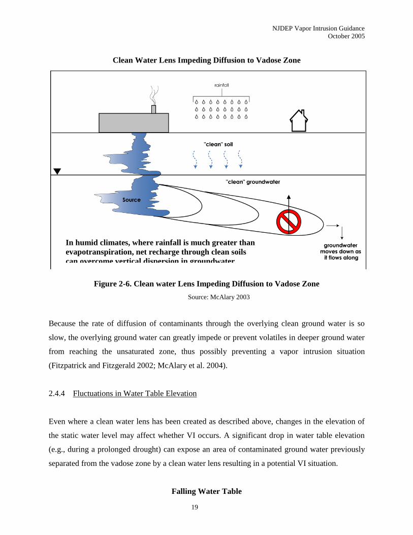
Clean Water Lens Impeding Diffusion to Vadose Zone
Figure 2-6. Clean water Lens Impeding Diffusion to Vadose Zone
Source: McAlary 2003
Because the rate of diffusion of contaminants through the overlying clean ground water is so
slow, the overlying ground water can greatly impede or prevent volatiles in deeper ground water
from reaching the unsaturated zone, thus possibly preventing a vapor intrusion situation
(Fitzpatrick and Fitzgerald 2002; McAlary et al. 2004).
2.4.4 Fluctuations in Water Table Elevation
Even where a clean water lens has been created as described above, changes in the elevation of
the static water level may affect whether VI occurs. A significant drop in water table elevation
(e.g., during a prolonged drought) can expose an area of contaminated ground water previously
separated from the vadose zone by a clean water lens resulting in a potential VI situation.
Falling Water Table
In humid climates, where rainfall is much greater than
evapotranspiration, net recharge through clean soils
can overcome vertical dispersion in groundwater

NJDEP Vapor Intrusion Guidance
October 2005
20
Figure 2-7. Falling Water Table Exposes Dissolved Plume to Vadose Zone
Source: McAlary 2003
If seasonal water table fluctuations are small relative to the thickness of the clean water lens,
then off gassing will be impeded. Where the lens is thin (2 to 3 feet) even normal water level
changes may result in the vertical movement of volatiles as depicted in Figure 2-7. This situation
increases the contaminated surface area where diffusion into the unsaturated zone can occur.
Some of those vapors may migrate far enough to cause VI into buildings and some can move
into and above the depth interval where the clean water lens previously existed and subsequently
partition back into the dissolved phase, contaminating capillary water and fresh recharge water
(Mendoza and McAlary 1990). Water table fluctuations may result in short term variation in
volatilization to the vadose zone over a few weeks to months. This variation could affect indoor
air concentrations where the pathway is already complete or change whether VI occurs. These
phenomena can have important implications for appropriate ground water sampling procedures
and for when soil vapor sampling is important.
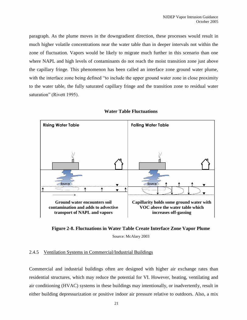
Figure 2-8 illustrates a situation where NAPL reaches the capillary fringe and/or soil is
contaminated with residual NAPL in the zone surrounding the capillary fringe. Fluctuations in
the water table could smear the product vertically and greatly enhance the phase transfer
“vertical mixing” between vapor and dissolved contamination discussed in the previous
NJDEP Vapor Intrusion Guidance
October 2005
21
paragraph. As the plume moves in the downgradient direction, these processes would result in
much higher volatile concentrations near the water table than in deeper intervals not within the
zone of fluctuation. Vapors would be likely to migrate much further in this scenario than one
where NAPL and high levels of contaminants do not reach the moist transition zone just above
the capillary fringe. This phenomenon has been called an interface zone ground water plume,
with the interface zone being defined “to include the upper ground water zone in close proximity
to the water table, the fully saturated capillary fringe and the transition zone to residual water
saturation” (Rivett 1995).
Water Table Fluctuations
Figure 2-8. Fluctuations in Water Table Create Interface Zone Vapor Plume
Source: McAlary 2003
2.4.5 Ventilation Systems in Commercial/Industrial Buildings
Commercial and industrial buildings often are designed with higher air exchange rates than
residential structures, which may reduce the potential for VI. However, heating, ventilating and
air conditioning (HVAC) systems in these buildings may intentionally, or inadvertently, result in
either building depressurization or positive indoor air pressure relative to outdoors. Also, a mix
Ground water encounters soil
contamination and adds to advective
transport of NAPL and vapors
Capillarity holds some ground water with
VOC above the water table which
increases off-gassing
NJDEP Vapor Intrusion Guidance
October 2005
22
of these two situations may occur depending on location within the building. Different floors of
multistory buildings may exhibit different pressure readings (e.g., negative pressure on lower
floors and positive pressure on upper floors). Therefore, prediction of potential soil gas entry
rates into these buildings would generally require site-specific assessment.
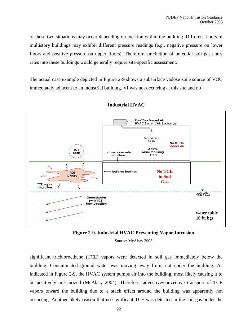
The actual case example depicted in Figure 2-9 shows a subsurface vadose zone source of VOC
immediately adjacent to an industrial building. VI was not occurring at this site and no
Industrial HVAC
Figure 2-9. Industrial HVAC Preventing Vapor Intrusion
Source: McAlary 2003
significant trichloroethene (TCE) vapors were detected in soil gas immediately below the
building. Contaminated ground water was moving away from, not under the building. As
indicated in Figure 2-9, the HVAC system pumps air into the building, most likely causing it to
be positively pressurized (McAlary 2004). Therefore, advective/convective transport of TCE
vapors toward the building due to a stack effect around the building was apparently not
occurring. Another likely reason that no significant TCE was detected in the soil gas under the
No TCE
in Soil
Gas
water table
10 ft. bgs
NJDEP Vapor Intrusion Guidance
October 2005
23
building is that the building footings were installed through most of the vadose zone thickness,
inhibiting lateral diffusion of TCE through the vadose zone to the area directly under the
building. It may be the combined affect of both the HVAC system and the building’s foundation
construction that prevented VI in this case.
Other case examples also indicate that commercial and industrial HVAC systems can create a
positive air pressure within a building (Berry-Spark et al. 2004), instead of the assumed negative
pressure indicated in Figure 2-4. All relevant building characteristics should be investigated and
included in the CSM. For commercial buildings, facility engineers can often provide
considerable detail on HVAC design and operations.

NJDEP Vapor Intrusion Guidance
October 2005
24
3.0 DECISION FRAMEWORK
The Decision Flow Chart (Appendix A) is designed to assist the investigator in assessing the
appropriate steps when evaluating the VI pathway. The chart was formulated to address most
typical situations where suspected indoor air impacts may have occurred due to sources outside
the building (e.g., soil or ground water contamination) or known spills inside the building. As
always, please consult the NJDEP case manager or technical support personnel for any
circumstances that are unique or present complex problems not fitting the paradigm.
The Department has utilized a phased approach to the investigation of the VI pathway. This
framework follows the basic provisions of the USEPA’s Draft Vapor Intrusion Guidance (2002b)
and incorporates both generic and site-specific procedures. Refer to Section 1.3 for further
discussion on the phased approach.
The Preliminary Assessment and Site Investigation phase encompasses those circumstances
where rapid action may be required. The Remedial Investigation phase employs generic
screening levels that can be compared to analytical data from indoor air, sub-slab or near slab
soil gas, and ground water samples to resolve whether there is the potential for this pathway to be
complete. At this time, generic screening levels for soil sample results have not been developed.
Site-specific parameters or alternative sampling approaches can be employed as part of the
remedial investigation. The Remediation and Monitoring phase addresses remedial actions and
monitoring requirements.
3.1 Preliminary Assessment and Site Investigation
Preliminary Assessment and Site Investigation (PA/SI) consists of three stages - a general
assessment of the VI pathway (Stage 1), a determination whether rapid action is warranted at the
site (Stage 2), and a comparison of available data to the generic screening levels.
In order for the VI pathway to be complete, there must be a source (principally volatile organic
compounds), a potential pathway involving an impacted matrix (e.g., groundwater, soil, and/or
NJDEP Vapor Intrusion Guidance
October 2005
25
soil gas), and an impacted receptor (current or future) proximal to the source or pathway. Stage 1
involves confirming that one or more contaminants of concern represent a potential risk due to
VI. In general, the compounds listed in Table 1 are the principal VI contaminants (although other
compounds may be added to the list in the future).
Stage 2 defines a series of situations where VI is likely to require rapid action. This action may
be limited to the prompt implementation of a VI investigation. Alternately, the decision may be
made that an interim (or emergency) remedial measure is required. These conditions include:
• Known spill in a structure (e.g., heating oil tanks);
• Physiological effects reported by occupants (with a known or suspected source nearby);
• Wet basement or sump with contaminated ground water nearby;
• Odors reported in a structure (with a known or suspected source nearby);
• Free product (as defined in N.J.A.C. 7:26E) at the water table under or immediately
adjacent to a structure; and,
• Other short-term safety concerns.
Consistent with the USEPA (2002b), short term safety concerns are “known, or are reasonably
suspected to exist, including: a) measured or likely explosive or acutely toxic concentrations of
vapors in a building or connected utility conduits, sumps, or other subsurface drains directly
connected to the building and b) measured or likely vapor concentrations that may be
flammable/combustible, corrosive, or chemically reactive.” For the purposes of Stage 2, odors
refer to “chemical” or “solvent” or “gasoline” complaints by occupants.
Professional judgment should be applied to these qualitative criteria when a determination is
made to implement a rapid action. The condition in question should be related to an event or
observation in or immediately adjacent to the structure in question. As with all indoor air
sampling events, the investigator should properly assess the relative impact from background
sources on the overall indoor air quality.
NJDEP Vapor Intrusion Guidance
October 2005
26
The Department has prepared Rapid Action Levels (RAL) in Table 2 that represent trigger levels
for the initiation of prompt action at occupied buildings to further investigate the VI pathway
and/or minimize impacts to building occupants through the implementation of an interim
remedial measure (IRM). The VI investigation can proceed following the mitigation of the RAL
exceedance. If a building is currently unoccupied, the rapid pace associated with the RAL is
unnecessary. The investigation and/or remedial action can proceed at the normal speed of
implementation.
In addition, Health Department Notification Levels (HDNL), developed in consultation with
NJDHSS, are also listed in Table 2. These values, when exceeded in occupied buildings,
indicate the need for the Department to inform the local and/or state health departments about the
site and the associated vapor intrusion related indoor air concentrations for further evaluation and
possible emergency actions. On a case by case basis, the health department may also be notified
when elevated indoor air levels below the HDNL are present in an occupied school, day care
center, health care facility, or other structure with sensitive receptors.
Stage 3 employs generic screening levels to determine whether the VI pathway warrants further
investigation and/or remediation based on existing data. The Department has developed these
screening values for ground water, indoor air and sub-slab or near slab soil gas. (Refer to
Appendix G for further discussion on the development of these screening levels.)
Ground water data should be compared to NJDEP Ground Water Screening Levels (GWSL) in
Table 1. When indoor air samples are collected, the results should be compared to the NJDEP
Indoor Air Screening Levels (IASL) in Table 1. The NJDEP Soil Gas Screening Levels (SGSL)
in Table 1 should be compared to the sub-slab and/or near slab soil gas results. Soil gas data
collected from exterior soil gas locations (as distinct from sub-slab or near slab) are generally not
appropriate for comparison to the SGSL. Refer to Section 6.3 (Exterior and Near Slab Soil Gas
Sampling Procedures) for further discussion on the applicability of exterior soil gas results.
Consistent with USEPA policy, the Department recommends a VI investigation where structures
are within 100 feet horizontally or vertically of shallow ground water contamination in excess of
NJDEP Vapor Intrusion Guidance
October 2005
27
the GWSL. Under a future use scenario, additional investigation may be necessary for
undeveloped parcels using the same criterion. If the depth to the shallowest ground water
exceeds 100 feet, a VI investigation is not required unless vertical preferential pathways exist
and the CSM indicates there is a significant VI risk. Section 6.2.1 includes further guidance
regarding this issue.
The 100-foot distance criterion for investigating the VI pathway does not consider the aerobic
biodegradation of petroleum hydrocarbons, particularly the BTEX compounds. Depending on the
site conditions, the criterion is likely to be too conservative for petroleum hydrocarbons.
Therefore, the Department will utilize a 30-foot distance criterion (both horizontal and vertical)
for petroleum related ground water contamination. (Refer to Chapter 9 for a clarification on
petroleum hydrocarbons, or PHCs.) The 30-foot PHC distance criterion is based, in part, on the
Pennsylvania VI guidance (2004).
If free product is present, the 100-foot distance criterion should be used, irrespective of the
chemical composition of the free product.
3.2 Remedial Investigation
The Remedial Investigation (RI) Phase involves the evaluation of the VI pathway.
If the current results reveal exceedances of the generic screening levels (or insufficient data
exists), a VI investigation workplan shall be prepared and implemented (Stage 4). Alternately,
the option of implementing a remedial action as a proactive approach may be considered.
The Department recommends ground water (in most circumstances) as the first medium to be
investigated for the VI pathway (Stage 4A). Unlike other states (e.g., California), the ground
water table across most of New Jersey is relatively shallow and ground water data is readily
available in the vicinity of the receptors. Thus, a ground water investigation is the appropriate
first stage for most VI investigation workplans. Section 6.2, Ground Water Investigation and
Sampling Procedures, should be consulted to ensure that the ground water data are both
NJDEP Vapor Intrusion Guidance
October 2005
28
representative and valid. In some instances, the Department may require sub-slab and indoor air
sampling concurrent with ongoing ground water and exterior soil gas investigations. Depending
on the site-specific CSM, the investigator may elect to conduct soil gas and/or indoor air
sampling prior to initiating a ground water investigation.
In cases where soil contamination represents a potential source of VI, the use of ground water
data and the GWSL alone are NOT appropriate. The investigator should employ soil gas and/or
indoor air samples to assess whether soil contamination is a source of VI.
Assuming the potential vapor source is not in the unsaturated zone (soil), no further investigation
of the VI pathway is required if appropriate ground water data are less than the NJDEP GWSL
(and free or residual product is not present at the water table). However, if the ground water data
exceed the screening levels, further investigation will be necessary.
The next stage of the VI investigation is the collection of soil gas samples (Stage 4B). Near slab
(or sub-slab) soil gas sampling allows the investigator to quantify contaminant levels in soil gas
immediately under or outside the foundation of the building. Section 6.3, Exterior or Near Slab
Soil Gas Sampling Procedures, provides the particular requirements for collecting near slab soil
gas samples. The procedures for collecting sub-slab soil gas samples are found in Section 6.4.
For assessing undeveloped parcels, exterior soil gas sampling can be employed using a grid
approach. The soil gas results from sub-slab, near slab, and exterior samples (where appropriate)
can be compared to the NJDEP SGSL. Exceedances of the SGSL will require further evaluation
of the VI pathway through the collection of indoor air data. Alternatively, the investigator may
elect to implement a remedial action to address the VI pathway.
Recognizing the difficulties associated with background contamination (among several issues),
indoor air sampling is typically the last step during a remedial investigation of the VI pathway
(Stage 4C) that provides the most direct evidence regarding the air quality within a building. All
other data (ground water, soil, sub-slab or near slab soil gas) simply reflect the potential for
adverse impact on indoor air quality based on modeling or attenuation factors, and not the actual
results. Thus, the Department recommends the collection of indoor air samples at this stage of
NJDEP Vapor Intrusion Guidance
October 2005
29
the investigation. Refer to Section 6.6 for more information on indoor air sampling procedures.
All indoor air samples (including crawl space air samples) should be compared to NJDEP IASL.
After consideration of background contamination and confirming the results, exceedances of the
IASL may require remedial action to mitigate the vapor intrusion (Stage 8).
One of the decision points in the generic screening process is to determine whether the data are
valid and representative. This is an all-inclusive phrase designed to address a variety of issues
dealing with the usability of the data. The provisions of this step include:
• Was the sampling plan designed to investigate the VI pathway (including seasonal
variability for indoor air samples), approved by NJDEP, and accurately followed by the
investigator?
• Were the samples properly collected - consistent with the NJDEP Field Sampling
Procedures Manual (2005) and this document?
• Is the investigator confident that the sampling equipment was not moved or otherwise
tampered with (some sampling events are left in place for extended periods without
supervision)?
• Were the samples validated (QA/QC) and determined to be acceptable?
• Was consideration given to potential background contamination?
• Were any other issues that might impact on the data’s usability addressed appropriately?
Each of the above provisions should be answered affirmatively in order to proceed along the
flow path. Any negative responses simply identify deficiencies in the data acquisition that
require the collection of additional data. Unless the data are determined to be valid and
representative (as discussed above), no conclusions can be made regarding the VI pathway.
3.3 Site-Specific Screening Options
At any point after Stage 3, the investigator can elect to utilize site-specific screening options as
part of the VI investigation. While the generic GWSL are based on the presence of sandy soils,
the Department has developed GWSL for Alternate Soil Textures (presented in Table 3 of the
NJDEP Vapor Intrusion Guidance
October 2005
30
document) based on loamy sand, sandy loam, and loam soil that result in less conservative
screening levels. Laboratory soil grain size analysis, as described in Section 5.2, is required to
justify the use of the GWSL for Alternate Soil Textures at a site.
Additional site-specific screening options that are available to the investigator (Stages 6 and 7)
include (but are not limited to):
a) Utilization of alternative soil gas sampling procedures (flux chambers, continuous
monitoring, vertical depth profiling);
b) Assessment of biodegradation for petroleum hydrocarbons (oxygen levels in subsurface
soils, depth to ground water table);
c) Development of alternate attenuation factors (with sub-slab or near slab soil gas);
d) Modifications to the J&E Model (depth to vapor source and overlying unsaturated zone
soil type);
e) Use of recent chemical toxicity, risk assessment methodology or exposure parameter
changes not yet reflected in the NJDEP guidance, in the generation of applicable IASL;
and,
f) Implementation of other appropriate site-specific screening options.
As discussed in Chapter 5 of the guidance, site-specific adjustments to the J&E model (including
specific building parameters) may be submitted to the Department for review and approval. An
institutional control on the property and regular monitoring (see Chapter 10) to protect against
changes in future use/building construction may be required.
Approval of any site-specific screening option should be obtained from NJDEP in advance of its
implementation as part of a VI investigative workplan. The workplan should incorporate
provisions to verify the effectiveness of the site-specific screening option to adequately assess
the VI pathway. In most cases this will involve the collection of additional field data. For
example, the investigator may want to utilize site-specific depth to vapor source and/or overlying
unsaturated zone soil type as part of the J&E modeling effort. The workplan should include a full
NJDEP Vapor Intrusion Guidance
October 2005
31
characterization of these parameters in the area of the inhabited building(s) being investigated (or
undeveloped areas where future construction is possible).
In another case, multiple buildings may exist over a ground water plume. The investigator may
propose to assess the VI risk using RI procedures for a representative number of “worst-case”
buildings and apply the results to the entire site (or expand the investigation if necessary based
on these results). The workplan should document the characteristic nature of the buildings
selected based on ground water concentrations, locations on the site, soil type, building
construction, and other factors NJDEP may deem appropriate. (Refer to Chapter 5 for further
discussion on the Site-Specific Screening Procedures.)
3.4 Remediation and Monitoring
Once the VI investigation is complete, a selection of the appropriate remedial action shall be
made. Consistent with N.J.A.C. 7:26E-5, a Remedial Action Selection Report (RASR) shall be
prepared (Stage 8). Chapter 10, Remedial Actions, should be consulted for guidance on the
applicable remedial alternatives.
An institutional control may be established within the limits of the ground water exceedance to
address future use of the overlying land. Depending on the degree of exceedance and other site
specific factors, current (and potentially future) inhabited buildings or environmental media may
be monitored to assess any VI risk. Building construction can incorporate remedial designs to
eliminate address the VI pathway. Engineering controls may be appropriate based on the results
of the remedial investigation, current/future land use and site conditions.
A Remedial Action Workplan (RAW) shall be prepared upon the Department’s approval of the
RASR (Stage 9). The RAW must include discussions on long term monitoring and maintenance
of the proposed remedial action (Stage 10).
Finally, the decision to terminate the proposed remediation upon remediation of the VI pathway
(Stage 11) can be addressed in the RA Progress Report.
NJDEP Vapor Intrusion Guidance
October 2005
32
4.0 GENERIC VAPOR INTRUSION SCREENING LEVELS
4.1 Introduction
The Department has developed Ground Water Screening Levels (GWSL), Indoor Air Screening
Levels (IASL) and Soil Gas Screening Levels (SGSL) to assist in the evaluation of potential VI
impacts at sites under review. The applicable screening levels are listed in Table 1. The
development of the screening levels is described in detail in Appendix G. As discussed in
Chapter 3, exceedances of the screening levels indicate that VI is of potential concern and that
further evaluation and/or potential remediation of the pathway is necessary.
The toxicity factors used in the development of the Department’s screening levels are based on
the USEPA Region III Risk Based Concentration (RBC) Table. USEPA Region III revises the
RBC table twice a year (April and October) based on new toxicity factor information and any
changes in the exposure parameters or calculation procedures. The Department will modify the
affected screening level values and associated tables based on updates to the RBC table shortly
after the information becomes available. The Department will also update the methodology used
to develop the screening levels and the analytical reporting limits values as the state of the
science advances.
Updates to the screening levels will be presented on the Department’s web site at
http://www.state.nj.us/dep/srp/guidance/vaporintrusion/. Modifications to the tables, since the
last version, will be marked with a double asterisk (**) adjacent to the name of the affected
chemical. It is recommended that users refer to the Department web site directly rather than rely
on printed versions of the tables to ensure that the most current information is used.
4.2 Ground Water Screening Levels
The Department has developed screening levels for ground water in order to protect against
unacceptable inhalation exposures to volatiles due to the migration of chemicals from
contaminated ground water to indoor air. The GWSL are shown in Table 1. The Department

NJDEP Vapor Intrusion Guidance
October 2005
33
used the Johnson and Ettinger (J&E) Model with New Jersey specific parameters, when
appropriate, in the development of the screening levels.
4.2.1 Application of the Ground Water Screening Levels
The USEPA states in its Draft Vapor Intrusion Guidance that the J&E model should not be used
when the distance between the water table and the building foundation is less than five feet
(USEPA, 2002b). Reasons for this include 1) the potential for seasonal fluctuations in the water
table to bring ground water in direct contact with the building foundation, and 2) the potential for
fill material, rather than native soil, to be present immediately under building foundations, and 3)
the potential for the soil capillary zone to extend up the building foundation. The difficulty with
the five-foot requirement is that New Jersey has many areas in the state with shallow ground
water and the five-foot requirement would result in many locations being eliminated from
consideration when using the ground water screening criteria. Since the screening level is
relatively insensitive to the groundwater depth (see Appendix G), the Department has adopted
slightly more liberal criteria for use of screening numbers calculated using the J&E model.
The Department’s ground water screening criteria may be used where the ground water is as
close as two feet below the building foundation when 1) the seasonal high water table does not
reach the building foundation, 2) the water table does not extend into fill material directly under
the building foundation, and 3) the top of the capillary zone does not reach the building
foundation. Regarding Item 3, the capillary zone does not normally extend through fill material
under buildings, which is typically coarse in nature. For situations where no fill material is
present under a building’s foundation, the top of the capillary zone may be estimated using Table
4-1. The capillary zone heights were calculated with the J&E model.

NJDEP Vapor Intrusion Guidance
October 2005
34
Table 4-1
Capillary Zone Heights for Select Soil Textures
Soil Texture Capillary Zone Height (cm) Capillary Zone Height (feet)
Sand 17 0.6
Loamy Sand 19 0.6
Sandy Loam 25 0.8
Sandy Clay Loam 26 0.9
Sandy clay 30 1.0
Loam 38 1.2
Clay Loam 47 1.5
Silty Loam 68 2.2
Clay 82 2.7
Silty Clay Loam 134 4.4
Silt 163 5.3
Silty clay 192 6.3
As indicated in Table 4-1, the capillary zone is greater than two feet in height for some soils with
silt and clay content. Therefore, the water table must be greater than two feet below the building
foundation in those situations. Site specific field determinations may be made in these
circumstances for soil texture.
Provided the above conditions are met, the Department’s GWSL are judged to be adequately
conservative for use at sites where unsaturated soil is present below the building foundation.
GWSL should not be applied where a building foundation is in direct contact with competent,
massive bedrock containing discrete fractured zones if vertical fractures are very likely to act as
preferential pathways for vapors (i.e., directly connecting contaminated ground water with
building foundations). The GWSL may be used for soils that contain gravel, assuming they
exhibit relatively homogeneous, isotropic conditions. The GWSL can also be applied (with
Department approval) where the water table is in bedrock and nearby site specific data indicate
there is unsaturated soil, fill, or geologic material below a building foundation through which
subsurface air flow would approximate, or approach, porous media conditions. In many areas
bedrock in the vadose zone and at the water table is so highly weathered and/or densely fractured
that these conditions will be met even if deeper, more competent bedrock creates very
heterogeneous flow conditions.
NJDEP Vapor Intrusion Guidance
October 2005
35
4.2.2 Degradation of BTEX Chemicals
It has been reported that oxygen levels above 4% are adequate for substantial degradation of
BTEX chemicals to occur within a short distance in the vadose zone (DeVaull et al. 1997). For
this reason, it has been suggested that an additional attenuation factor should be applied to the
screening values in order to account for degradation of these chemicals. Suggested values for this
degradation dilution factor are 3-10 (USEPA 2002b), 1-100 (Hers et al. 2004), 100-1000
(Fitzpatrick and Fitzgerald 2002) and 500-35,000 (Ririe et al. 2002). Thus far, the database is
small regarding hydrocarbon attenuation factors. However, it appears that the additional
attenuation factor is at least 10-1 (Hers 2004). For this reason, the GWSL listed in Table 1 for
benzene, toluene, ethylbenzene and xylene are set at ten times the value calculated using the J&E
model.
4.3 Indoor Air Screening Levels
Residential and nonresidential IASL to be used in the evaluation of indoor air analytical results
are presented in Table 1 and are discussed below. The IASL are based on the USEPA Region III
Ambient Air Risk Based Concentrations (RBC) Table. The NJDEP screening levels represent the
higher of the health-based (RBC) indoor air values and the USEPA Method TO-15 analytical
reporting limits (as defined in Appendix G). Screening levels indicating the need for more
prompt action at a site are presented in Table 2. The basis of the screening levels is discussed in
Appendix G.
4.3.1 Application of the Indoor Air Screening Levels
The applicable IASL, after consideration of the analytical reporting limits, are presented in Table
1. The values are presented in both ug/m3 and ppbv units. When site data are compared with the
screening levels, the user should ensure that the concentrations and the screening levels are both
in the same units (ppbv or ug/m3).
Consistent with the proposed Soil Standards regulations, the Department requires the use of the
residential IASL in the evaluation of residential properties, schools and day care centers. There
NJDEP Vapor Intrusion Guidance
October 2005
36
may also be situations where other site-specific exposures occur that will be evaluated on a case
specific basis.
The nonresidential IASL are applicable to industrial/commercial facilities where the adult is the
receptor of concern. The Department’s current policy requires that the nonresidential IASL are
applicable to commercial/industrial sites when a discharge to the environment has occurred and
the facility is not currently handling or using the subsurface contaminants of concern associated
with the discharge. The evaluation of VI at facilities currently using the same chemicals present
in the discharge impacted media (e.g., ground water) should include consideration of both the
nonresidential screening levels and the applicability of the OSHA PEL to the subject building.
As discussed in Chapter 10, the option to use the nonresidential IASL and/or the OSHA PEL is
contingent upon obtaining an institutional control at the affected structure(s) to address potential
future changes in site use. Nonresidential settings with sensitive populations (such as pregnant
workers) will be handled on a site-specific basis.
While the Department does not subtract background air concentrations from the analytical
results, site-specific background sources may be considered when interpreting indoor air data.
Background contaminant levels, particularly ambient air results, may supercede the Table 1
values when higher since the Department does not require remediation to levels below
background concentrations. Background determinations are made on a site-specific basis in
consultation with the Department and as part of the overall multiple lines of evidence approach
(see Chapter 8).
4.3.2 Alternate Indoor Air Screening Levels
As discussed in Chapter 5, Alternate IASL may be developed for a site as a site-specific
evaluation based on chemical toxicity factor changes on IRIS or the USEPA Region III RBC
Table that have not yet been reflected in the most recent NJDEP Vapor Intrusion Guidance
document. Alternate IASL may also be developed based on recent changes in the risk assessment
methodologies or exposure parameters that have not yet been included in the Department’s
Vapor Intrusion Guidance. As noted in Section 4.1, the Department will incorporate toxicity
NJDEP Vapor Intrusion Guidance
October 2005
37
changes from the USEPA Region III RBC Table used to develop the screening levels shortly
after the updated information becomes available.
4.3.3 Rapid Action and Health Department Notification Levels
The Department has developed indoor air concentrations to determine when prompt actions are
indicated to address the potential for adverse VI related impacts. Table 2 presents Rapid Action
Levels (RAL) to be used when evaluating site related indoor air analytical data. The table
includes RAL values for thirteen chemicals that the Department has found to be the primary
contaminants that drive remedial actions at VI impacted sites.
The RAL values represent trigger levels for the initiation of a rapid action at occupied buildings
to further investigate the VI pathway and/or minimize impacts to building occupants through an
interim remedial measure. Since, as described below, the RAL values are based on a residential
exposure scenario, nonresidential facilities that do not include residential uses (e.g., apartments),
schools and/or day care centers, may be evaluated on a site-specific basis. The RAL values are
not applicable to nonresidential facilities currently handling the VI contaminant(s) of concern
that are subject to OSHA requirements for that chemical. Potential change in future use,
however, must be considered in the evaluation of these sites.
By policy, the Department has based the RAL values on a factor of 100 times the cancer health-
based residential IASL or a factor of 2 times the noncancer health-based residential IASL
(presented in Table G-4). The Department has based the RAL value for trichloroethene (TCE)
on the Health Department Notification Level (discussed below) for TCE due to the current
controversy concerning the appropriate toxicity factor for the chemical.
Health Department Notification Levels (HDNL), developed in consultation with the New Jersey
Department of Health and Senior Services (NJDHSS), are also listed in Table 2. These values,
when exceeded in occupied buildings, represent levels that trigger the Department’s referral of a
site to the local health department and/or NJDHSS. The local health department and/or NJDHSS
would use this information to make a decision in consultation with the NJDEP regarding the
need for any emergency actions, such as the evacuation of an occupied building. On a case by
NJDEP Vapor Intrusion Guidance
October 2005
38
case basis, the health departments may also be notified when elevated indoor air levels below the
HDNL are present in an occupied school, day care center, health care facility, or other structure
with sensitive receptors.
The HDNL are based on one-half of the Agency for Toxic Substances Disease Registry
(ATSDR) acute duration Minimum Risk Level (MRL) or 1,000 times the cancer health based
residential indoor air value in Table G-4, whichever is lower. The intermediate duration MRL is
used in the absence of an acute MRL.
Should the driver chemical at a site be a volatile contaminant that does not currently have a RAL
or HDNL value, the Department’s Environmental Toxicology and Risk Assessment (ETRA) unit
may be contacted at 609-633-1348 to identify an applicable action level.
4.4 Soil Gas Screening Levels
SGSL developed by the Department for the evaluation of the VI pathway are presented in Table
1. The SGSL are used in the evaluation of representative and appropriate (see Chapter 6) sub-
slab soil gas and/or near slab soil gas analytical results. Exceedence of the SGSL indicates the
potential for VI that necessitates further evaluation of the pathway as outlined in Chapters 3 and
7.
As discussed in Appendix G, the SGSL are based on the higher of the health-based soil gas
screening values and the soil gas analytical reporting limits presented in Table G-6. The health-
based soil gas screening values were calculated by dividing the unrounded health-based indoor
air values by an attenuation factor (α) of 0.02.
The attenuation factor and health-based soil gas screening values will be updated as the state of
the science advances and as new information becomes available from USEPA. Site-specific
attenuation factors and SGSL may be developed as a part of the remedial investigation (see
Chapter 5).
NJDEP Vapor Intrusion Guidance
October 2005
39
5.0 SITE-SPECIFIC SCREENING PROCEDURES
This chapter discusses site-specific screening options available for the evaluation of the VI
pathway. The use of a site-specific option to address the pathway will, in general, require the
collection of more detailed site information. Departmental approval of the alternative approach
should be obtained by the investigator prior to its implementation in the evaluation of a site. As
discussed in Chapter 3, use of an alternative methodology must also include provisions in the
associated VI investigative workplan to verify the effectiveness of the site-specific screening
approach with actual field data. It should be noted that use of the options described below in
Sections 5.1 and 5.2 is subject to the same limitations applied to the generic screening criteria
(see Section 4.2.1).
5.1 Default Screening Numbers for Alternate Soil Textures
Using the J&E model, the Department has developed GWSL for Alternate Soil Textures, which
are shown in Table 3. The levels were developed using the same “default” values and
assumptions used in the generic GWSL except for those based on soil texture. Table 3 includes
screening levels for loamy sand, sandy loam and loam soil textures. Values for vadose zone soil
bulk density, total porosity, and water filled porosity are built into the J&E spreadsheet and set
according to the selected soil texture. Laboratory soil grain size analysis of soil samples (Section
5.2.3) is required for acceptable use of the Table 3 screening levels as well as for other site-
specific screening options discussed below. Acceptable use of the Table 3 screening levels
requires that at least 75% of the soil vertical profile be as fine as the selected soil texture. If this
criterion is not met, the coarsest soil texture must be used.
5.2 Site-Specific Use of the J&E Model for Calculation of VI GWSL
Site-specific modeling of VI may be accomplished using the J&E model. However, the allowed
uses of the model for site-specific analysis are limited. While the input parameters of the J&E
model are adjustable for site-specific conditions, some of them have no effect on the calculated
screening level, many of them have only a moderate effect, and many parameters are not
NJDEP Vapor Intrusion Guidance
October 2005
40
amenable to site-specific measurement. Therefore, only a few parameters are practical for site-
specific adjustment as summarized in Section 5.2.7. The potential for each class of input
parameters to be adjusted is discussed in detail in Sections 5.2.1 through 5.2.6. Instructions for
using the J&E spreadsheets have been published (USEPA 2004d). Only Version 3.1 (or later
versions), available from the USEPA Office of Solid Waste and Emergency Response, may be
utilized (www.epa.gov/oswer/riskassessment/airmodel/johnson_ettinger.html).
5.2.1 Chemical Properties
The chemical properties (organic carbon partition coefficient, Henry’s law constant, diffusivity
in air, diffusivity in water, water solubility, boiling point, critical temperature and enthalpy of
vaporization) are fixed constants and not subject to change. While variable numerical values for
these constants have been reported in the literature, the Department has decided to rely on the
same data sources used in the USEPA Draft Vapor Intrusion Guidance (USEPA 2002b) and in
the USEPA Soil Screening Guidance document (USEPA 1996a). See Appendix G for more
information. Chemical properties will be updated as needed in future revisions of this document.
5.2.2 Toxicological and Exposure Parameters
USEPA Region III based unit risk factors (URF) and reference concentrations (RfC) have been
used in the development of the screening levels presented in this document. While the
Department will update the screening levels based on toxicity factor changes in the latest USEPA
Region III Risk Based Concentration (RBC) Table, site-specific evaluations may be submitted
that incorporate new IRIS or Region III based toxicity factors that have not yet been incorporated
into the screening levels. The target risk level of 10-6 and the target hazard quotient of 1 may not
be adjusted.
While the generic GWSL are based on a residential exposure scenario (as discussed in Appendix
G), site-specific GWSL under a nonresidential (worker) exposure scenario may be developed for
a site. The following USEPA exposure assumptions may be used for a nonresidential (worker)
scenario:
NJDEP Vapor Intrusion Guidance
October 2005
41
• Exposure duration - 25 years. (Averaging time for noncarcinogens must be changed
to 365 days x 25 years)
• Exposure frequency - 250 days/year
• Child adjustment factor (discussed in Appendix G) - may be eliminated under the
worker scenario. This adjustment allows use of the J&E model output without
multiplying the screening level by a factor of 0.74 (or 0.26 for vinyl chloride) that
accounts for childhood exposure.
• The USEPA recommended averaging time for carcinogens may not be changed and is
fixed at 70 years.
The exposure parameters used in the J&E model may be modified as a site-specific option based
on recent changes in the risk assessment methodologies or exposure parameters that have not yet
been included in this document.
Note that the option of using the above nonresidential exposure parameter values, or any other
values other than the generic residential screening values (excluding toxicity factor and risk
assessment methodology updates), will require an institutional control necessary to protect for
future change in the use of the property.
5.2.3 Soil Texture
This parameter has a large effect on the calculated screening level and may be changed from the
most conservative texture, sand, if adequate site-specific information is obtained. The use of
soil textures finer than loam is allowed only if it can be demonstrated that these soils are not
fractured. Alternately, a sand soil texture may be used when modeling these fine soil textures.
Sand may also be used for soils that contain gravel, assuming they exhibit porous media
conditions.
The Department’s acceptance of an alternate soil texture shall be based on soil texture analysis.
To establish soil texture, collect soil cores using a Shelby Tube, direct push sampler, or split

NJDEP Vapor Intrusion Guidance
October 2005
42
spoon. One representative boring within 10 feet of the structure will be sufficient for most single
family homes with additional borings necessary for larger structures. The soil cores/samples
should be collected continuously (every two or four feet depending on the length of the sampling
device) from the base of the foundation depth to the surface of the static water level. A grain size
analysis is then completed on the cores/samples. A variety of methods exist to determine grain
size of a given soil sample. The Department will consider any of the following techniques
acceptable: sieve analysis for the sand and gravel portions of a given sample with pipette or
hydrometer measurements of the silt and clay fractions, rapid sediment analyzers, or electro-
resistance multichannel particle size analyzers.
Figure 5-1
The percentages of sand, silt and clay determined by the chosen analysis techniques are then
compared to the USDA Soil Texture Triangle to determine the soil texture classification (Figure
5-1 above). Under the USDA Soil Texture Triangle below, sands are considered particles
between 0.05 mm and 2 mm in size, silts are between 0.05 mm and 0.002 mm and clays are less
than 0.002 mm in size.
NJDEP Vapor Intrusion Guidance
October 2005
43
Site-specific J&E modeling using a single soil texture for the entire vadose zone requires that at
least 75% of the soil vertical profile be as fine as the selected soil texture. If this criterion is not
met, the coarsest soil texture must be used.
The Department’s GIS has a Soil Survey Geographic Database (SSURGO) available which
indicates the surface soil texture for most of New Jersey, with the exception of older urban areas
(United States Department of Agriculture 1999). The SSURGO data layer should be examined in
conjunction with the soil boring logs for a particular site of interest as a cross check to confirm
that the correct soil texture is being used. This data may also provide a basis for requiring
multiple soil boring locations per single family residence if it indicates horizontal changes in soil
texture are likely across the building footprint.
When entering soil texture in the J&E spreadsheet, it must be entered in each cell where soil
texture input is possible. The advanced spreadsheet (GW-ADV) has the capability of entering
different textures for different soil stratums. This should be allowed only when adequate soil
boring data is available to indicate that these layers are continuous across the site under
investigation.
5.2.4 Soil Physical and Chemical Properties
Practical, routine field methods are not available for determination of vadose zone bulk density,
porosity and soil water-filled porosity. Thus, site-specific values for these parameters may not be
substituted for the default values set according to soil texture. When soil texture is entered, the
soil properties should be altered by clicking on the “Lookup soil parameters” in the J&E
spreadsheet.
Soil vapor permeability is not used in the calculations for the Department screening levels. This
parameter would be used to calculate the soil gas entry rate, Qsoil, but this latter parameter is
instead fixed at the USEPA recommended value of 5 L/min when using the J&E spreadsheet.
The Department does not allow the use of soil vapor permeability measurements for determining
NJDEP Vapor Intrusion Guidance
October 2005
44
Qsoil or screening level values because of the high level of variability of this measurement. It is
only in soils immediately surrounding the foundation (i.e. the “zone of influence”) where Qsoil is
operative. Often, coarse grained fill material is placed below a building foundation, which is
typically more porous than soils near the building foundation. Therefore, soil vapor permeability
measurements of the soil surrounding the building are likely to be unrepresentative of the
permeability conditions immediately below the foundation.
Soil organic carbon is fixed in the J&E spreadsheet at a fractional value of 0.002 and may not be
changed. However, this value does not affect the screening level when the source of the
contamination is the ground water (see Appendix G).
5.2.5 Building Parameters
Some building parameters may be adjusted site-specifically to calculate a site-specific ground
water screening level. Note that adjustment of building parameters is an option that will result in
an institutional control on the property and regular monitoring of the parameter by the
responsible party to protect against future use modifications. The following parameters are
allowed to be entered in the advanced version of the spreadsheet (Qsoil may also be entered in
the screening version of spreadsheet).
Air exchange rate - The default air exchange rate is 0.25 exchanges/hour. This parameter may be
adjusted site-specifically. The air exchange rate of the lowest floor of the building should be
used. The ground water screening level is inversely proportional to the air exchange rate.
Soil gas entry rate - This parameter is dependant on many variables, including soil permeability,
the building depressurization, the building perimeter, various crack parameters, and the soil
vapor permeability. As discussed previously, calculation of the soil gas entry rate is subject to
considerable uncertainty, particularly with regard to soil vapor permeability. Therefore, the use
of the advanced J&E spreadsheet for calculation of this parameter from the soil vapor
permeability is not allowed. A base value of 5 L/min is recommended by USEPA and has been
adopted by the Department for a residential building. However, this value is inappropriate for
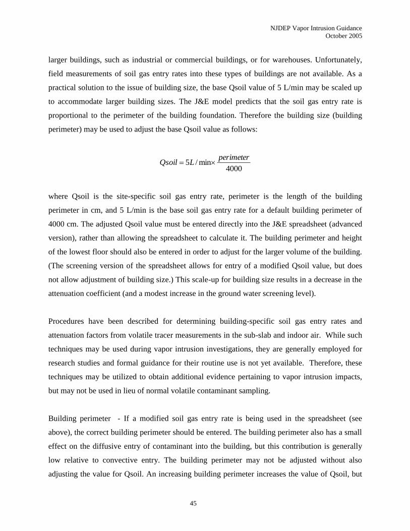
NJDEP Vapor Intrusion Guidance
October 2005
45
larger buildings, such as industrial or commercial buildings, or for warehouses. Unfortunately,
field measurements of soil gas entry rates into these types of buildings are not available. As a
practical solution to the issue of building size, the base Qsoil value of 5 L/min may be scaled up
to accommodate larger building sizes. The J&E model predicts that the soil gas entry rate is
proportional to the perimeter of the building foundation. Therefore the building size (building
perimeter) may be used to adjust the base Qsoil value as follows:
4000min/5
perimeterLQsoil
where Qsoil is the site-specific soil gas entry rate, perimeter is the length of the building
perimeter in cm, and 5 L/min is the base soil gas entry rate for a default building perimeter of
4000 cm. The adjusted Qsoil value must be entered directly into the J&E spreadsheet (advanced
version), rather than allowing the spreadsheet to calculate it. The building perimeter and height
of the lowest floor should also be entered in order to adjust for the larger volume of the building.
(The screening version of the spreadsheet allows for entry of a modified Qsoil value, but does
not allow adjustment of building size.) This scale-up for building size results in a decrease in the
attenuation coefficient (and a modest increase in the ground water screening level).
Procedures have been described for determining building-specific soil gas entry rates and
attenuation factors from volatile tracer measurements in the sub-slab and indoor air. While such
techniques may be used during vapor intrusion investigations, they are generally employed for
research studies and formal guidance for their routine use is not yet available. Therefore, these
techniques may be utilized to obtain additional evidence pertaining to vapor intrusion impacts,
but may not be used in lieu of normal volatile contaminant sampling.
Building perimeter - If a modified soil gas entry rate is being used in the spreadsheet (see
above), the correct building perimeter should be entered. The building perimeter also has a small
effect on the diffusive entry of contaminant into the building, but this contribution is generally
low relative to convective entry. The building perimeter may not be adjusted without also
adjusting the value for Qsoil. An increasing building perimeter increases the value of Qsoil, but
NJDEP Vapor Intrusion Guidance
October 2005
46
causes a greater increase in building volume, thus increasing the attenuation coefficient and
decreasing the ground water screening level.
Building height - If a modified soil gas entry rate is being used in the spreadsheet (see above),
the height of the lowest floor of the building should be entered. The building height may not be
adjusted without also adjusting the values of Qsoil and the building perimeter. At a constant air
exchange rate, increasing the building height increases the value of the ground water screening
level.
Building depressurization - This parameter is used along with other parameters (e.g., soil vapor
permeability) to calculate soil gas entry rates. Since this calculation is not allowed (see above),
modification of this parameter is not allowed. EXCEPTION: HVAC systems on some
commercial buildings are run under positive pressure conditions (i.e., pressure in the building
interior is greater than that on the exterior). In cases such as these, soil gas entry would be
eliminated, and diffusion of contaminant through the building foundation would also be
inhibited. If these conditions can be demonstrated, the VI pathway in this instance may be
deemed incomplete and site-specific modeling is unnecessary. This may result in no further
action for the VI pathway. Note that this option will necessitate an institutional control requiring
positive pressure conditions be maintained and periodic monitoring by the responsible party to
protect against any changes in future use and elimination of the positive pressure control.
Floor-wall seam crack width - This parameter affects the soil gas entry rate and also affects
diffusive contaminant entry. As discussed above, this parameter is not allowed to be used to
calculate a modified soil gas entry rate. Furthermore, diffusive contaminant entry is generally
small relative to soil gas convection. Therefore, the effect of this parameter on the attenuation
coefficient is small. The Department does not allow modification of this parameter.
Enclosed floor thickness - This parameter effects diffusive transport only. Since this transport
mechanism is generally insignificant relative to convective transport, modification of this
parameter is unnecessary and not allowed by the Department.
NJDEP Vapor Intrusion Guidance
October 2005
47
Depth of the building foundation - The depth of the building foundation is only relevant in that it
affects the depth interval between the building foundation and the water table. This parameter
may be adjusted site-specifically in the advanced version of the J&E spreadsheet (GW-ADV), or
changed to slab depth (15 cm) in the screening version of the spreadsheet. However, the
appropriate depth to ground water must also be entered.
5.2.6 Depth to Ground Water
The depth to ground water has a relatively small effect on the calculated GWSL. Site-specific
adjustment of this parameter, however, is allowed and does not require an institutional control on
the property.
5.2.7 Summary of Site-Specific J&E Modeling for Calculation of GWSL for the VI Pathway
For the J&E spreadsheets, USEPA guidance should be consulted (USEPA 2004d). Using
procedures discussed above, the parameters in Table 5-1 may be adjusted in the J&E model.
Appendix G provides further discussion regarding these input parameters, including sensitivity
analyses.
Unless multiple soil layers or altered building parameters are being used, the GW-SCREEN
spreadsheet should be used instead of GW-ADV. If a standard building foundation depth is being
used (200 cm for basement construction, 15 cm for slab on grade construction), the GW-
SCREEN spreadsheet is adequate unless other building parameters are being adjusted.
When calculating site-specific VI ground water screening levels for carcinogenic compounds, the
J&E model output must be multiplied by 0.74 (or 0.26 for vinyl chloride) to account for the child
exposure factor unless a worker scenario is being modeled.
For possible site-specific adjustment of the GWSL beyond those discussed in this document, the
Department’s case team should be consulted.
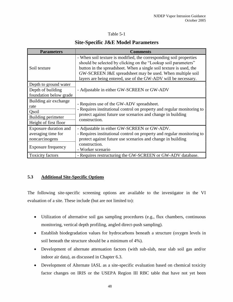
NJDEP Vapor Intrusion Guidance
October 2005
48
Table 5-1
Site-Specific J&E Model Parameters
Parameters Comments
Soil texture
- When soil texture is modified, the corresponding soil properties
should be selected by clicking on the “Lookup soil parameters”
button in the spreadsheet. When a single soil texture is used, the
GW-SCREEN J&E spreadsheet may be used. When multiple soil
layers are being entered, use of the GW-ADV will be necessary.
Depth to ground water
- Adjustable in either GW-SCREEN or GW-ADV Depth of building
foundation below grade
Building air exchange
rate - Requires use of the GW-ADV spreadsheet.
- Requires institutional control on property and regular monitoring to
protect against future use scenarios and change in building
construction.
Qsoil
Building perimeter
Height of first floor
Exposure duration and
averaging time for
noncarcinogens
- Adjustable in either GW-SCREEN or GW-ADV.
- Requires institutional control on property and regular monitoring to
protect against future use scenarios and change in building
construction.
- Worker scenario Exposure frequency
Toxicity factors - Requires restructuring the GW-SCREEN or GW-ADV database.
5.3 Additional Site-Specific Options
The following site-specific screening options are available to the investigator in the VI
evaluation of a site. These include (but are not limited to):
• Utilization of alternative soil gas sampling procedures (e.g., flux chambers, continuous
monitoring, vertical depth profiling, angled direct-push sampling).
• Establish biodegradation values for hydrocarbons beneath a structure (oxygen levels in
soil beneath the structure should be a minimum of 4%).
• Development of alternate attenuation factors (with sub-slab, near slab soil gas and/or
indoor air data), as discussed in Chapter 6.3.
• Development of Alternate IASL as a site-specific evaluation based on chemical toxicity
factor changes on IRIS or the USEPA Region III RBC table that have not yet been
NJDEP Vapor Intrusion Guidance
October 2005
49
reflected in the most recent NJDEP Vapor Intrusion Guidance document. Alternate IASL
may also be developed based on recent changes in the risk assessment methodologies or
exposure parameters that have not yet been included in the NJDEP Vapor Intrusion
Guidance document.
• Implementation of other appropriate site-specific screening options.
Approval of any site-specific option should be obtained from the Department in advance of its
implementation as part of a VI investigative workplan. All site-specific options must be
supported by site-specific data. The workplan shall incorporate provisions (field data) to verify
the effectiveness of the site-specific screening option to adequately assess the VI pathway (i.e.,
demonstrate the calculated result is verifiable in the site-specific situation for which it is being
applied).
NJDEP Vapor Intrusion Guidance
October 2005
50
6.0 SAMPLING PROCEDURES AND INVESTIGATION
REQUIREMENTS
6.1 Preparation of a Vapor Intrusion Workplan
If the Department requires the submission of a VI investigation workplan, the workplan shall be
prepared consistent with the Technical Requirements for Site Remediation (N.J.A.C. 7:26E-4.2).
In the event that an investigator is conducting a VI investigation without departmental oversight,
submittal of a workplan is not required. However, it is highly recommended that the
investigator seek approval for any deviations from this guidance prior to conducting the
sampling event. If the investigator decides to conduct the investigation without submitting a
workplan and receiving approval, it should be recognized that any deviations from this guidance
may result in rejection of the data. In addition, when submitting the results of the sampling event,
the investigator should provide adequate rationale justifying any deviations from this guidance
whether or not they were previously approved by the Department.
6.1.1 Conceptual Site Model
The CSM is the starting point for the preparation of a VI investigation workplan. As previously
stated, NJDEP strongly recommends early development of a written, illustrated CSM that can be
used to plan, scope, and communicate the development of a VI investigation workplan and any
needed remedial actions.
The CSM will allow the investigator to better understand the source of contaminants, the
pathways traveled, the receptors or entities potentially or actually exposed to contaminants, and
the location of each component in relation to the others. Buildings with known sensitive
populations (e.g., schools, day cares) should be identified early in the process and prioritized for
investigation.
Armed with this information, a VI investigation workplan can be prepared.
NJDEP Vapor Intrusion Guidance
October 2005
51
6.1.2 General Issues
The most basic question an investigator asks when evaluating VI is “When do I have to assess
this pathway?”
Utilizing the Decision Flow Chart (Appendix A), the initial decision points for the VI pathway
are to assess the potential for VI (Stage 1) and determine whether the site necessitates a rapid
action or Stage 2. An affirmative Stage 2 determination for occupied buildings will require the
prompt investigation of the VI pathway to assess the necessity for remedial action. Confirmation
of the VI-related exceedance of the RAL will necessitate that an interim remedial measure be
implemented immediately.
More than likely, though, the investigator will move to the next decision point - evaluating
existing data against the screening levels (Stage 3).
The Department considers ground water in excess of the NJDEP GWSL to be a potential source
of VI that can adversely impact indoor air quality of nearby structures. Consistent with USEPA,
the VI pathway warrants investigation when a structure is “located within approximately 100 feet
laterally or vertically of known or interpolated soil gas or ground water contaminants … and the
contamination occurs in the unsaturated zone and/or the uppermost saturated zone.” (USEPA
2002b) Further clarification on the distance criteria, including the adjustment for petroleum
hydrocarbons, can be found in Chapter 3.
Existing soil gas (sub-slab or near slab only) or indoor air data should be compared to the
NJDEP SGSL and IASL, respectively. Exceedances of these screening levels will necessitate
further evaluation and possible remedial action of the VI pathway.
6.1.3 Investigative Tools
There are a number of investigative methods for assessing the VI pathway, involving ground
water, soil gas and indoor air sample collection.

NJDEP Vapor Intrusion Guidance
October 2005
52
6.1.3.1 Ground Water Sampling
In most situations, ground water will be the first medium to be evaluated for the VI pathway
(Stage 4A). A site-wide remedial investigation will require the characterization and delineation
of ground water contamination. The extent of the ground water plume, as well as the
concentrations of the contaminants, will allow for an initial assessment of the VI pathway. Any
exceedance of the NJDEP GWSL will necessitate further evaluation and probably more field
investigation.
Section 6.2 below and the Technical Requirements for Site Remediation (N.J.A.C. 7:26E) should
be followed for all ground water investigations. Quality assurance issues (e.g., QA samples,
analytical methods, deliverables) for ground water sampling should be consistent with the most
recent version of the NJDEP Field Sampling Procedures Manual.
As a general rule, the collection of soil gas or indoor air samples is not recommended prior to a
basic assessment of the site hydrogeology, including soil stratigraphy, ground water depth and
flow direction, and contaminant concentrations. False assumptions may be reached on the VI
pathway based on an incomplete picture of the site hydrogeology (as defined in the CSM). It
should be understood, though, Stage 2 may necessitate the collection of sub-slab soil gas and/or
indoor air samples prior to acquisition of sufficient ground water data due to the urgency of the
potential human exposure. The presence, quantity, and location of NAPL in the vadose zone may
also indicate that the collection of soil gas and/or indoor air samples should precede collection of
ground water analytical data.
6.1.3.2 Soil Gas Sampling
An exceedance of the NJDEP GWSL will necessitate further investigation of the VI pathway.
Soil gas sampling (Stage 4B) is the most logical next step in the VI investigative process.
In this guidance, NJDEP defines soil gas results based on the location of the sample - sub-slab
(below the foundation slab), near slab (within 10 feet horizontally of the foundation), or exterior
NJDEP Vapor Intrusion Guidance
October 2005
53
(outside of the 10-foot perimeter). In addition, data can be obtained from passive soil gas
sampling procedures.
Depending on the investigative scenario encountered, different applications of soil gas sampling
may be appropriate.
When ground water contamination in excess of the GWSL extends near or under a building
(using the appropriate distance criteria), the Department recommends the collection of sub-slab
soil gas samples to verify the presence of elevated soil gas concentrations immediately below the
building foundation/slab. The sub-slab soil gas results will provide empirical data essential in
properly evaluating risk to human receptors within the structure.
When the collection of sub-slab soil gas samples is not feasible, the results of near slab soil gas
sampling may be utilized (with the Department’s approval) to determine whether the VI pathway
is currently complete for a particular building. Refer to Sections 6.3 and 6.4 (Exterior or Near
Slab Soil Gas Sampling Procedures and Sub-Slab Soil Gas Sampling Procedures, respectively)
for additional requirements.
Undeveloped parcels without existing structures present a unique situation for the investigation
of the VI pathway. The collection of sub-slab soil gas or indoor air samples is not possible
without a structure on the parcel. In this case, the Department recommends as an option that
exterior soil gas samples be utilized to assess the potential for VI under a future use scenario. A
grid sampling approach (approximately 100 x 100 feet) should be employed across the site and
biased towards the highest concentrations within the ground water plume. The suggested soil gas
depth is 8-10 feet below ground surface (equivalent to the depth of a typical basement). Site-
specific modifications to the sample depth may be appropriate based on current municipal
zoning, projected construction activities, or hydrogeological parameters.
Only in situations where the exterior soil gas investigation is being conducted to assess a future
use scenario at an undeveloped parcel should the results be compared to the NJDEP SGSL.
NJDEP Vapor Intrusion Guidance
October 2005
54
Exterior soil gas samples can also be employed to assist with the delineation of the ground water
plume. However, final plume delineation should be supported by the collection of confirmatory
ground water samples at strategic locations. In these cases, a mobile lab employing USEPA
Method 8260B (or similar methods) may expedite the investigation and allow the flexibility to
modify the sampling strategy in the field (Triad approach).
The results of the sub-slab and near slab soil gas samples are compared to the NJDEP SGSL.
The NJDEP SGSL are applied to samples collected at a minimum depth of 5 feet below the
ground surface and in the vadose zone no closer than one foot above the capillary fringe. A
shallow ground water table may prevent the collection of representative or valid soil gas samples
due to high moisture content within the gas sampled and/or dilution due to atmospheric air being
drawn down from the surface. The only exception to the 5-foot depth rule is for soil gas samples
collected from a central location below a shallow or at grade impermeable slab, including
driveways, parking lots, building slabs, and garage floors.
In situations where contaminated unsaturated soils are the primary potential source, sub-slab or
near slab soil gas samples are the principal mechanism for investigating the VI pathway (other
than indoor air samples).
Underground storage tank sites or sites where chlorinated solvents are used in buildings or
facilities at the surface (e.g., dry cleaners, vapor degreasers) may have contamination in the
vadose zone due solely to vapor leaks. In these cases, soil and/or ground water data may not
identify the VI source. Soil gas data are the preferable investigative tools where vapor leaks (or
vapor clouds) are suspected. The vapor cloud phenomenon is discussed in Chapter 2.
Sites that involve contaminated unsaturated soils or vapor leaks are two examples where a
vertical profile of soil gas concentrations may assist in the investigation. Vertical profiling can
better clarify the source(s) of VI by evaluating the distribution of chemical concentrations over a
defined depth. If a ground water plume under a structure is the suspected source, soil gas
concentrations should increase as the depth of the soil collection increases. Deviations from this
NJDEP Vapor Intrusion Guidance
October 2005
55
general assumption may suggest an alternative source, such as preferential pathways, vapor leaks
or vadose zone soil contamination.
Sub-slab or near slab soil gas samples may also be more appropriate when obtaining truly
representative ground water data is not possible or is impractical.
Lastly, passive soil gas sampling may be applicable to the preliminary delineation of the ground
water plume. Final plume delineation should be supported by the collection of confirmatory
ground water samples at strategic locations.
6.1.3.3 Indoor Air Sampling
Indoor air sampling is generally the last investigative step in the evaluation of the VI pathway
(Stage 4C). Due to legitimate concerns over background sources, indoor air results provide a
unique challenge to investigators (refer to Chapter 8, Background Indoor Air Contamination, for
additional information). The Department recommends the collection of sub-slab and ambient air
samples in conjunction with indoor air sampling events (Stage 4C) to assist in the evaluation of
background contaminant sources.
Despite the problems, indoor air sampling is often necessary to properly assess whether the VI
pathway is complete. These situations include:
• Exceedances of the SGSL;
• Shallow ground water table that prevents the collection of soil gas data;
• Site-specific approach is utilized which requires supplemental data in support of
the conclusions;
• Preferential pathways exist that may negate or limit the usefulness of ground
water or soil gas data;
• Stage 2 conditions that require a more immediate response;
• Volatiles in bedrock near or at the surface which eliminates the use of the J&E
Model; and,
• Other site-specific factors.

NJDEP Vapor Intrusion Guidance
October 2005
56
Since indoor air sample locations are a critical issue in the ultimate assessment of the data, the VI
investigation workplan should clearly identify the criteria that will be employed in this selection
process. Refer to Conducting a Building Walkthrough and Survey (Section 6.5) for additional
guidance on this phase of the investigation.
An ambient air sample provides background concentrations outside of the building being
investigated at the time of the indoor air sampling event. When using USEPA Method TO-15,
the canister used for the ambient air sample should be randomly selected from the canisters sent
by the laboratory and placed outside of a building that is being sampled. The ambient air sample
shall have the same sample collection time and be analyzed in the same manner as the interior
sample. The investigator should clearly designate where the sample is collected and the site
conditions at the time of sampling. The investigator also should be aware of the weather
conditions during the sampling event. It is highly recommended that the canisters be placed in a
secure outside location and not in front of a building. Ambient air samples should be taken at
breathing zone height and as far from auto traffic or other potential sources as possible.
The number of ambient (outside) canisters recommended is a minimum of 1 per sampling event
with the maximum of twenty (20) samples being associated with each ambient (outside) canister.
However, if the sampling event occurs over multiple days, additional ambient (outside) canisters
may be recommended at the discretion of NJDEP. Additionally, if the spatial arrangement of the
sampling points is dispersed and background cannot be easily defined, additional ambient
(outside) canisters may be recommended.
In situations where ambient levels for contaminants of concern are expected to be elevated based
on the nature of the commercial/industrial/retail operation, the investigator should consider
avoiding the collection of indoor air samples. For example, at active gasoline service stations, if
ground water contaminant concentrations exceed the GWSL, the Department recommends the
collection of sub-slab soil gas samples where possible in lieu of indoor air samples. If the sub-
slab results are in excess of SGSL, an institutional control may be required at the site until it can
be demonstrated the site contaminant concentrations do not represent a VI risk.
NJDEP Vapor Intrusion Guidance
October 2005
57
Depending on the site conditions, the volatile concentrations in ground water, and seasonal
variability, one round of indoor air samples will likely not be sufficient to verify the
presence/absence of the VI pathway. A second (or confirmation) round of indoor air samples
may be appropriate. At a minimum, a confirmation sample is necessary to eliminate the VI
pathway when the initial sample is collected outside the winter/early spring timeframe
(November through March). Modifications to this provision may be appropriate based on site-
specific information.
In the case of initial indoor air results that exceed RAL, confirmation samples should be
collected immediately to verify these exceedances.
6.1.3.4 Soil Sampling
At this time, generic screening levels for soil results have not been developed. Soil gas and
indoor air results can be evaluated to assess the vapor potential from contaminated soils.
Otherwise, a site-specific determination will have to be made as to whether further investigation
of the VI pathway is warranted for contaminated soils.
6.1.4 Preferential Pathways
Due to the nature of vapor migration, all VI investigation workplans must assess the presence of
preferential pathways.
The Pennsylvania Department of Environmental Protection (2004) defines preferential pathways
as:
“…a natural (e.g., shallow rock or vertically fractured soil) or manmade (e.g.,
buried utilities) feature that creates a sufficiently direct pathway from a source to
a receptor to make the use of the default model for predicting indoor air
concentrations unacceptable.”
NJDEP Vapor Intrusion Guidance
October 2005
58
The investigator should evaluate the possibility of interconnections between ground water and
any subsurface utilities (e.g., storm sewers, sanitary sewers, water lines). In these cases, the
depth of the invert, the diameter of the conduit, and the construction specifications of utility lines
should be determined. The investigator should also determine whether any utilities may be acting
as conduits for vapor migration, either along the utility's backfill or within the utility itself. This
determination should include, but not be limited to, visual inspection and the use of field
screening instruments (with appropriate detection limits based on the SGSL). Additional
information on assessing utility corridors as part of a VI investigation can be found in the State
of Wisconsin guidance document (2000).
Based upon the results of this evaluation, the investigator may be required to canvass the
immediate area of concern, locate all subsurface utilities and basements, and determine the
presence/absence of organic vapors in accordance with N.J.A.C. 7:26E-4.4(h)3.viii. The exact
locations of all subsurface utilities and basements should be plotted on a scaled site map.
Depending on the site conditions, periodic inspections of the subsurface utilities may be required
with readings of oxygen levels, and lower explosive levels (LEL). In addition, the presence of
organic vapors within the utility corridors should be documented by collecting passive or active
soil gas samples.
6.1.5 VI Report Requirements
The VI Report should address a series of issues related to documenting the sampling event. In
addition to the requirements in N.J.A.C. 7:26E-4.8, the following provisions should be included
in the VI Report:
1. Copies of the Indoor Air Building Survey and Sampling form;
2. Scaled site maps identifying the site, adjacent streets, buildings sampled (soil gas/indoor air),
ambient air sample locations;
3. Photographs of sample locations (as appropriate) or other pertinent site features;
4. Readings from field instrumentation;
5. Any documentation, including scaled maps, on the assessment of preferential pathways; and,
NJDEP Vapor Intrusion Guidance
October 2005
59
6. Scaled floor plans that note location of indoor air and sub-slab soil gas samples, observed
stains and major cracks in slabs/foundations, sumps, French drains, existing radon systems,
chemical storage areas (or other potential background sources), HVAC systems, utility
entrances into buildings, etc.
6.2 Ground Water Investigation and Sampling Procedures
Section 6.2 discusses: 1) saturated zone features affecting VI; 2) use of pre-existing ground water
data; and 3) obtaining new ground water data to evaluate this pathway.
6.2.1. Saturated Zone Features Affecting Vapor Intrusion
Many of the concepts and properties discussed below are more applicable to subsurface
formations where the ground water flow regime is relatively homogeneous (e.g., unconsolidated
or sedimentary formations), however, more heterogeneous flow regimes are also addressed in
several discussions. Topics include:
• Clean Water Lens
• Depth to Saturated Zone and Stratigraphy
• Fluctuations in Depth to Saturated Zone
• Complex Hydrogeologic Settings
• Proximity to Preferential Pathways
• Potential for Contaminant Degradation.
6.2.1.1 Clean Water Lens
Published and non-published research and case data indicate that ground water concentrations of
volatiles in a small depth interval close to the water table are a better predictor of the presence,
and relative concentrations, of volatiles in soil gas or indoor air than are volatile levels in slightly
deeper saturated intervals (Fitzpatrick and Fitzgerald 2002; Hers and Rees 2005; McAlary et al.
2004; Rivett 1995; Marrin and Thompson 1987). If a clean water lens exists above the volatile
NJDEP Vapor Intrusion Guidance
October 2005
60
contamination, it can act as a barrier to volatilization from deeper ground water (Rivett 1995).
This could reduce or prevent VI into overlying buildings (see Figure 2-6).
As a ground water plume migrates downgradient from its source area it is subject to a number of
processes. Some of the processes favor the formation of a clean water lens while others may
prevent its formation or may eliminate such a lens soon after it forms. Where precipitation and
other waters (lawn irrigation, septic systems, leaking sewer or water supply lines, etc.) can
infiltrate and/or percolate to the water table through clean soil/sediments, a clean water lens is
likely to form (Weaver and Wilson 2003; USEPA 2001e).
Other stratigraphic and/or hydrogeologic properties (e.g., layer with higher permeability,
downward hydraulic gradient) could also cause a plume to dive in the downgradient direction
(Weaver et al. 1999), possibly thickening the clean water lens as ground water migrates away
from the source area. Upward hydraulic gradients and minimal infiltration of precipitation due to
impermeable surface cover both discourage formation of a clean water lens. A clean water lens
may form and disappear multiple times depending on factors discussed in Subsection 6.2.1.3.
Where a clean water lens is an important element of the CSM, multi-depth sampling (i.e.,
vertical profiling) within discrete intervals in a well or boring may be appropriate. An increase in
ground water density due to contamination with DNAPL is generally not a cause for a diving
plume (Schwille 1988).
A clean water lens that is thicker than the annual water table fluctuation range can be a
significant barrier to off-gassing of volatiles from ground water to soil gas. If a clean water lens
is thin, relative to short term, seasonal, and/or longer term drops in the water level (natural or
manmade) it is likely that a falling water table will expose a plume to the vadose zone (see
Figure 2-7).

NJDEP Vapor Intrusion Guidance
October 2005
61
6.2.1.2 Depth to Saturated Zone and Stratigraphy
The water table can be described as the shallowest depth at which ground water will freely flow
into wells, or other ground water sampling devices. The depth to the regional water table and/or
any perched saturated zone(s) needs to be determined in the vicinity of buildings at risk for VI.
The vertical distance between the most shallow saturated zone and building foundations should
also be determined. A “perched” water table is one with unsaturated materials beneath it, and
usually occurs only where a low permeability layer is present in the unsaturated zone and
recharge is sufficient to exceed the percolation rate through this layer.
As indicated in Section 4.2, where the top of the saturated zone is in very fine grained soil or
sediments, the intergrain pores (i.e., original or primary pores) will be quite small, and as a
result, the capillary fringe above the water table will be quite thick; it also can be fully saturated
closer to the water table. The presence and concentration of volatiles in such a saturated interval
just above the water table would greatly affect off-gassing into the vadose zone, however it may
be impractical to obtain a ground water sample from that interval. In such soils, representative
soil gas volatile data will likely be a much better indicator than ground water data of the VI risk.
This is also likely where vadose zone soil borings indicate a thick, laterally extensive, organic
rich layer (Hughes et al. 1996).
Boring or test pit logs in the area of a VI investigation should be used to:
• evaluate the soil profile, soil type and texture throughout the profile;
• look for stratigraphic changes or soil horizons indicative of high moisture content, a
perched water table, or high organic carbon content; and,
• evaluate characteristics of the strata immediately below and above the water table.
The depth of the water table and/or first zone of saturation should be determined in order to:
• help determine ground water flow direction (with surveyed ground surface elevations);
• decide appropriate media for further investigation; and,
• determine the depth of ground water sampling.
NJDEP Vapor Intrusion Guidance
October 2005
62
6.2.1.3 Fluctuation in Depth to Saturated Zone
Changes in water table elevation may increase or decrease the risk of VI. The cause of the water
level change and the proximity and nature of the source of the ground water contamination (e.g.,
age, size) affect the potential for VI. The water table elevation fluctuates and perched saturated
zones may dry up seasonally or only exist periodically after precipitation events. If a perched
saturated zone is present, extensive enough, and clean, it could prevent migration of vapors
through it, or around it, from underlying contaminated ground water.
Where free product has migrated along the water table, a rising water level could increase the
risk of VI to nearby structures, especially if the rise in water level was not caused by local
ground water recharge (e.g., flooding near a river, swollen from rain or snow melt in locations
far upstream). If the overlying soil/sediment is clean and only dissolved phase ground water
contamination is present, a rise in water level due to local recharge may form a clean water lens
and reduce the risk of VI.
Significant fluctuations in the water table elevation also affect the predictability of VI using
analytical modeling approaches where ground water quality is the source input parameter. Proper
ground water sampling design may overcome this potential limitation but use of ground water
samples that represent worst case conditions and/or use of soil gas data is more acceptable to
NJDEP for modeling in such situations.
6.2.1.4 Complex Hydrogeologic Settings
Heterogeneity in subsurface media could have a significant impact on whether volatiles in
saturated zones become a source for VI. Information on the locations and depths of near surface
features such as clay, till or gravel layers/lenses and depth to bedrock must be considered for an
adequate evaluation. Such features should be taken into account when determining saturated
zone sampling depth intervals and whether ground water data can be utilized to evaluate VI risk.
NJDEP Vapor Intrusion Guidance
October 2005
63
For example, sampling of potable wells drawing from a bedrock aquifer underlying indoor air
receptors may show volatile contamination, but ground water in the overburden above the
bedrock may be clean. If there is bedrock immediately beneath a building or bedrock outcrops
nearby (such that it bisects the saturated zone in the overburden near the structure), vapors from
the bedrock aquifer contamination may be able to migrate to the ground surface if unsaturated
vertical fractures, faults, solution channels or other secondary pores/openings provide a
migration conduit. In that situation, ground water quality in the bedrock near such features may
be just as relevant as nearby shallow ground water quality in the overburden. However, given the
difficulty and expense of bedrock investigations, subsurface gas sampling and/or indoor air
sampling would be a more practical and, probably, a more accurate investigative approach where
bedrock aquifer contamination is likely to cause VI.
6.2.1.5 Proximity to Preferential Pathways
Preferential pathways in the unsaturated zone (defined in Section 2.2.4) could allow rapid and/or
laterally significant vapor transport. To the extent it is feasible and safe, VI investigations should
consider the proximity of contaminated ground water to unsaturated preferential pathways. The
30- or 100-foot criteria (see Section 3.2) may not be adequately conservative where preferential
pathways connect structures with areas of subsurface NAPL contamination or ground water/soil
concentrations indicative of the presence of NAPL (e.g., plume source area with suspected
residual DNAPL is more than 100 feet side gradient of structures but buried utility bedding
connects it with structures). This is more likely a concern for contaminants that do not
aerobically biodegrade readily.
6.2.1.6 Potential for Contaminant Degradation
Many contaminants associated with petroleum hydrocarbons, including benzene, toluene,
ethylbenzene and xylene (BTEX) compounds are readily biodegraded in the vadose zone
(Thompson and Marrin 1987). As such, they are less likely to complete the VI to indoor air
pathway than most chlorinated VOC. Even where LNAPL occurs in close proximity to
structures, rapid biodegradation in the vadose zone may preclude a complete pathway. Therefore,
NJDEP Vapor Intrusion Guidance
October 2005
64
soil gas sampling (e.g., vertical profiling of volatiles, O2 and CO2) will usually be more relevant
than ground water sampling for evaluating the risk of VI when GWSL are exceeded.
Biodegradation of petroleum hydrocarbon contaminants is discussed in Chapter 9.
6.2.2 Use of Pre-Existing Ground Water Data
In many situations shallow ground water data that are already available prior to initiation of a VI
investigation are sufficient to use as part of a VI investigation, especially if ground water
contamination has been delineated and the plume has reached steady state conditions (i.e., no
longer expanding). In deciding whether existing data are sufficient, consideration should be
given to the site-specific CSM and the data should be from wells screened across the water table
at the time of sampling. If the vertical thickness of the water column in a well is greater than 10
feet, supplemental data may be recommended on a case by case basis.
In addition, the likelihood of significant vertical changes in ground water quality near the water
table, the sampling method used, the construction of existing wells sampled (e.g., screen length
and placement across water table), the type of contaminants present, and heterogeneity of the
vadose zone and shallow saturated zone media will likely be the most important factors in
determining whether existing data are sufficient. Proposals to supplement existing ground water
data with some type of soil gas data, instead of new ground water data, may also be considered.
6.2.2.1 Interpolation of Nearby Data
If ground water data immediately upgradient from the structure are not available, surrounding
data points can be used to construct contaminant iso-concentration maps. However, this should
only be done if data points are available on at least two sides of a structure. Complex geologic
settings or the anticipated presence of steep concentration gradients warrant a denser sampling
grid.
NJDEP Vapor Intrusion Guidance
October 2005
65
6.2.2.2 Use of Drinking Water Well Data
Since 1985, New Jersey statutes and/or regulations have required that private or public drinking
water supply wells be constructed with at least 50 feet of casing. For this and other reasons it is
likely that few drinking water wells in New Jersey are screened/open across the water table. It is
much more likely that they draw ground water from depths at least 10 feet or more below the
local water table. It is also likely that drinking water supply wells in consolidated bedrock
formations are not often drawing water from water bearing zones that are in widespread, direct
contact with the vadose zone immediately above the well. Therefore, the presence of volatiles in
private or public drinking water wells should be considered a possible basis for further
investigation, but in most situations the data should not be compared to GWSL.
6.2.3 Obtaining New Ground Water Data to Evaluate the VI Pathway
If the evaluations discussed above indicate that new or additional ground water data are needed
to complete the VI investigation, the goal of the sampling effort should be to determine volatile
concentrations in shallow ground water beneath or near potential structures.
Direct push sampling methods and passive diffusion bag samplers are two ground water
sampling methods NJDEP recommends for obtaining discrete interval samples (i.e., from a
distinct, defined interval) in the uppermost intervals of shallow ground water. Vertical profiling
in discrete intervals within the top 10 feet (or less) of the saturated zone may be recommended
(see subsection 6.2.3.2 below). Low flow purging and sampling may provide adequate data to
evaluate this pathway in many situations. Volume-averaged purging and sample collection (i.e.,
conventional method) is not well suited to generate new ground water data specifically for VI
evaluations.
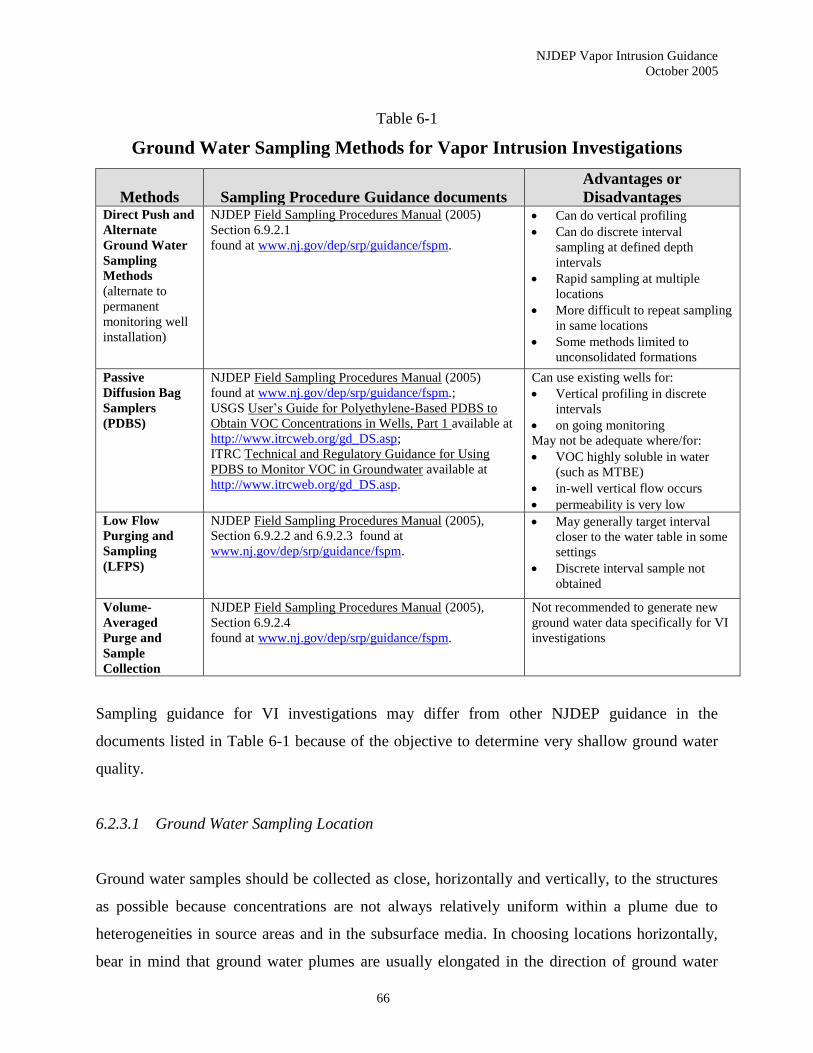
NJDEP Vapor Intrusion Guidance
October 2005
66
Table 6-1
Ground Water Sampling Methods for Vapor Intrusion Investigations
Methods
Sampling Procedure Guidance documents
Advantages or
Disadvantages Direct Push and
Alternate
Ground Water
Sampling
Methods
(alternate to
permanent
monitoring well
installation)
NJDEP Field Sampling Procedures Manual (2005)
Section 6.9.2.1
found at www.nj.gov/dep/srp/guidance/fspm.
• Can do vertical profiling
• Can do discrete interval
sampling at defined depth
intervals
• Rapid sampling at multiple
locations
• More difficult to repeat sampling
in same locations
• Some methods limited to
unconsolidated formations
Passive
Diffusion Bag
Samplers
(PDBS)
NJDEP Field Sampling Procedures Manual (2005)
found at www.nj.gov/dep/srp/guidance/fspm.;
USGS User’s Guide for Polyethylene-Based PDBS to
Obtain VOC Concentrations in Wells, Part 1 available at
http://www.itrcweb.org/gd_DS.asp;
ITRC Technical and Regulatory Guidance for Using
PDBS to Monitor VOC in Groundwater available at
http://www.itrcweb.org/gd_DS.asp.
Can use existing wells for:
• Vertical profiling in discrete
intervals
• on going monitoring
May not be adequate where/for:
• VOC highly soluble in water
(such as MTBE)
• in-well vertical flow occurs
• permeability is very low
Low Flow
Purging and
Sampling
(LFPS)
NJDEP Field Sampling Procedures Manual (2005),
Section 6.9.2.2 and 6.9.2.3 found at
www.nj.gov/dep/srp/guidance/fspm.
• May generally target interval
closer to the water table in some
settings
• Discrete interval sample not
obtained
Volume-
Averaged
Purge and
Sample
Collection
NJDEP Field Sampling Procedures Manual (2005),
Section 6.9.2.4
found at www.nj.gov/dep/srp/guidance/fspm.
Not recommended to generate new
ground water data specifically for VI
investigations
Sampling guidance for VI investigations may differ from other NJDEP guidance in the
documents listed in Table 6-1 because of the objective to determine very shallow ground water
quality.
6.2.3.1 Ground Water Sampling Location
Ground water samples should be collected as close, horizontally and vertically, to the structures
as possible because concentrations are not always relatively uniform within a plume due to
heterogeneities in source areas and in the subsurface media. In choosing locations horizontally,
bear in mind that ground water plumes are usually elongated in the direction of ground water
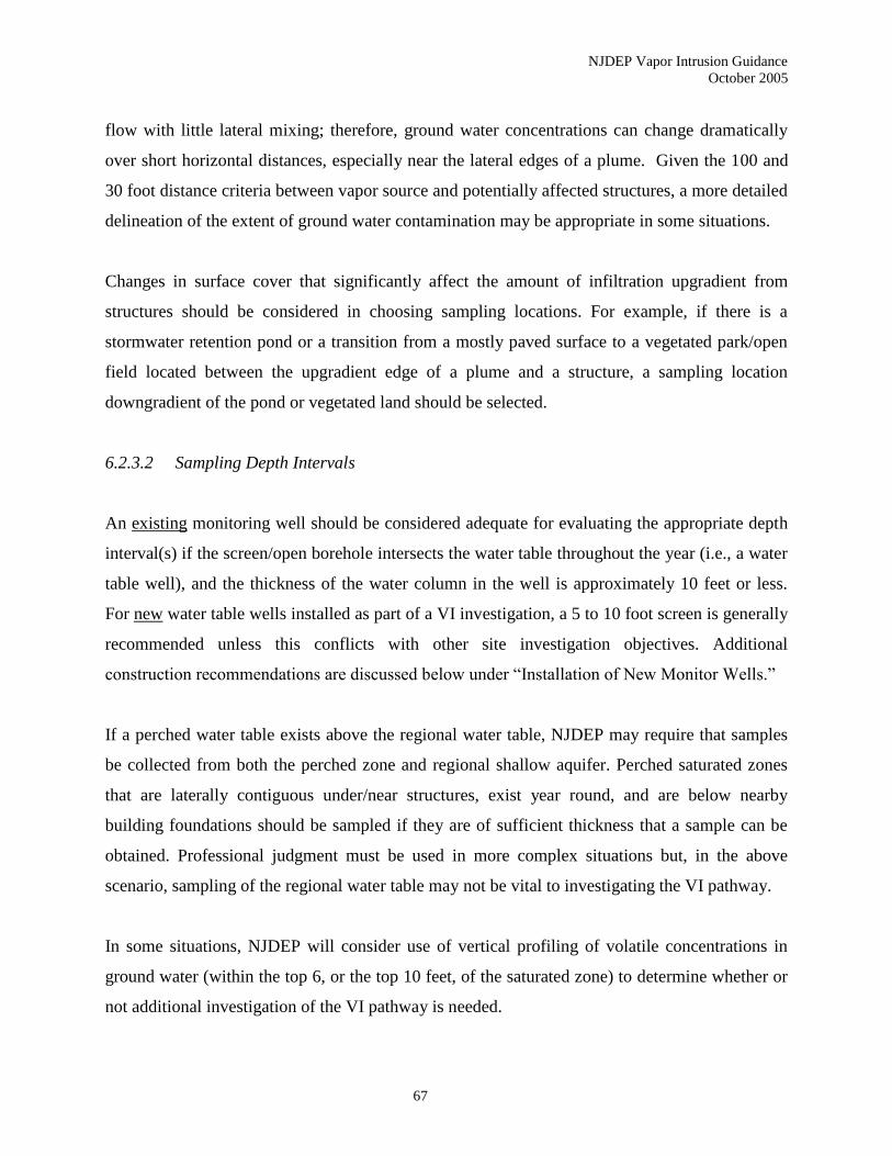
NJDEP Vapor Intrusion Guidance
October 2005
67
flow with little lateral mixing; therefore, ground water concentrations can change dramatically
over short horizontal distances, especially near the lateral edges of a plume. Given the 100 and
30 foot distance criteria between vapor source and potentially affected structures, a more detailed
delineation of the extent of ground water contamination may be appropriate in some situations.
Changes in surface cover that significantly affect the amount of infiltration upgradient from
structures should be considered in choosing sampling locations. For example, if there is a
stormwater retention pond or a transition from a mostly paved surface to a vegetated park/open
field located between the upgradient edge of a plume and a structure, a sampling location
downgradient of the pond or vegetated land should be selected.
6.2.3.2 Sampling Depth Intervals
An existing monitoring well should be considered adequate for evaluating the appropriate depth
interval(s) if the screen/open borehole intersects the water table throughout the year (i.e., a water
table well), and the thickness of the water column in the well is approximately 10 feet or less.
For new water table wells installed as part of a VI investigation, a 5 to 10 foot screen is generally
recommended unless this conflicts with other site investigation objectives. Additional
construction recommendations are discussed below under “Installation of New Monitor Wells.”
If a perched water table exists above the regional water table, NJDEP may require that samples
be collected from both the perched zone and regional shallow aquifer. Perched saturated zones
that are laterally contiguous under/near structures, exist year round, and are below nearby
building foundations should be sampled if they are of sufficient thickness that a sample can be
obtained. Professional judgment must be used in more complex situations but, in the above
scenario, sampling of the regional water table may not be vital to investigating the VI pathway.
In some situations, NJDEP will consider use of vertical profiling of volatile concentrations in
ground water (within the top 6, or the top 10 feet, of the saturated zone) to determine whether or
not additional investigation of the VI pathway is needed.
NJDEP Vapor Intrusion Guidance
October 2005
68
Vertical profiling is recommended or may be warranted where:
• A clean water lens is likely to be present;
• Certain site-specific screening options will be used; and,
• Direct push or any discrete-interval ground water sampling method is used to obtain new data
to evaluate this pathway.
Sections 6.2.1.1, 2.4.3 and 2.4.4 cover the processes and site characteristics that favor the
formation of a clean water lens. Development of the CSM should include evaluation of
whether a clean water lens is likely to be present and/or if volatile levels below the GWSL are
likely to be at or near the water table.
If a site-specific GWSL has been approved by the Department (excluding Table 3) or if ground
water data will be used to develop a site-specific ground water to indoor air attenuation factor,
vertical profiling may be warranted. Large vertical changes in ground water volatile
concentrations often occur within a 5 to 10 foot vertical interval (Vroblesky 2001; Reilly and
Gibs 1993; and Puls and Paul 1998). If a clean water lens is not present these changes are
usually not relevant to whether the GWSL are exceeded because the GWSL are very
conservative. These changes may be relevant if the above options are utilized. Flexibility
regarding this recommendation is reasonable based on site-specific characteristics or data (e.g.,
existing site data may indicate that vertical changes in volatile concentrations are likely to be
negligible).
Vertical profiling is recommended however if a site-specific GWSL has been approved by the
Department (not including the levels in Table 3) and if ground water data will be used to develop
a site-specific ground water to indoor air attenuation factor.
If discrete-interval ground water sampling methods are used, vertical profiling may oftern be
appropriate. However, site-specific data may suggest that significant vertical changes are
unlikely or could not be detected by some methodologies due to site conditions (e.g., vertical
flow within a well screen/open hole saturated interval).
NJDEP Vapor Intrusion Guidance
October 2005
69
Where vertical contaminant profiling is done, NJDEP generally recommends sampling within, at
least, the top 6 feet of the saturated zone, and possibly the top 10 feet. Site-specific
considerations may warrant altering the total depth interval for profiling.
Changes in regional water-table elevation (~1 to 3 feet) are relatively common. Profiling should
extend to 10 feet below the water table (bwt) in situations where/when significant drops in the
water table elevation (more than about 4 feet) are likely. Significant decline in the water level
elevation may be caused by shallow or deeper zone ground water withdrawals, changes in
surface cover or management of stormwater runoff, and prolonged drought.
The exact depth intervals below the water table that should be targeted as part of vertical
profiling depend on sampling methodology and site-specific information. Generally, at least two
different depth intervals within the top 6 feet of the saturated zone should be targeted for
sampling. Method specific guidance is given below. If profiling extends to 10 feet bwt, one
sample from the 6 to 10 foot interval is generally recommended for any method utilized.
Profiling should be done in at least one boring or well. Multiple borings/well locations may be
recommended where a large number of structures overlie a large plume.
Vertical profiles of shallow ground water contamination may enable a more precise evaluation of
the current and potential future risk of VI in some situations.
6.2.3.3 Direct Push and Alternative Ground Water Sampling Methods
Where the geologic formation allows it, NJDEP may accept data obtained using direct push
methods or other alternate/temporary ground water sampling techniques as part of the VI
investigation. Due to the advantages listed in the above table, alternate and direct push sampling
methods are often well suited for VI investigations especially if attempting to determine the
depth of the interface between a shallow clean water lens and an underlying plume.

NJDEP Vapor Intrusion Guidance
October 2005
70
Obtaining samples that target the 0 to 3-foot and 3 to 6-foot intervals from the top of the
saturated zone may be sufficient. However, as discussed above, one additional sample from the 6
to 10 foot interval bwt should be obtained where significant changes in the water table elevation
are likely. Small changes of these intervals are appropriate if a sufficient volume of water can not
be obtained or if site-specific data supports sampling alternate intervals. The intervals sampled
should be documented and justified as part of the vapor intrusion work plan.
Direct push/alternate sampling locations should be accurately mapped and documented. The
boring location should be marked, if possible, to facilitate subsequent re-sampling. Repeated
sampling over time at the same locations may be necessary for some sites to determine if shallow
ground water quality has changed due to water table elevation fluctuations or other factors.
Ongoing monitoring recommendations are discussed below.
6.2.3.4 Monitoring Well Sampling Methods for VI Investigations
As stated in subsection 6.2.3.2, only water table wells should be used in most situations. Well
sampling methods that can target the upper few feet of the screened interval (or open borehole)
are recommended for gathering new data, but are not necessary in every situation in order to
adequately address the VI pathway. As previously discussed, if a site’s conceptual model and/or
other information indicate that a vertical profile should be obtained, PDBS can be used for well
sampling if appropriate as specified below.
Passive Diffusion Bag Samplers (PDBS). The NJDEP FSPM (Section 6.9.2.5.1) should be the
initial source for information on PDBS.
PDBS should not be used for acetone, styrene, methyl-tert-butyl ether (MTBE), and 4-methyl-2-
pentanone (MIBK). PDBS that are about 20 inches long should be used for a VI investigation. A
minimum of two, but potentially three PDBS should be strung together to evaluate the vertical
profile of ground water quality in the top six feet of the saturated zone. If profiling should extend
to the 6 to 10 foot interval bwt, usually one PDBS deployed in the central portion of that interval
NJDEP Vapor Intrusion Guidance
October 2005
71
will be sufficient. This guidance differs from the vertical profiling provisions of the FSPM due to
the specific VI objective of determining very shallow ground water quality.
PDBS may be deployed in a well for a minimum of two weeks to equilibrate with the well water.
Significant water table fluctuations during that period will affect the appropriate depth intervals
for the samplers. If the water level drops below the uppermost sampler transfer of volatiles from
the sampler water into less contaminated well air space would occur. If the upper sampler is
exposed to the air space, the upper sampler should be resuspended two feet below the current
water level and retrieved after an additional two-week equilibration period.
As indicated in subsection 6.2.3.2, sampling that includes the 0 to 2-foot interval below the water
table would provide a better indicator of the potential for VI. Where periodic water level data
are available, the uppermost PDB sampler should be set within the 1 to 2-foot interval below the
current water level if the historic water level data indicate it will remain submerged. Otherwise,
it should be set at least 2 feet bwt. In wells where there is likely to be more significant lowering
of the water level during PDBS deployment, the upper sampler should be set so that it remains
submerged during the entire equilibration period. Measuring water levels in a well before and
several times following significant precipitation events may help investigators anticipate the
degree of fluctuation to expect. Avoid initial placement of the samplers immediately after
precipitation or snow melting events, if possible. NJDEP encourages innovative approaches to
allow sampling the shallowest interval while avoiding exposure of the uppermost sampler. In
any event, the depth to water in the well should be measured when the PDBS are installed and
removed, and the position of the samplers relative to the water level should be clearly described
in the report presenting the PDBS data.
Currently, PDBS are not recommended for sampling in formations with a hydraulic conductivity
of less than 1 x 10⁻⁶ cm/s because testing in such tight formations has not been conducted. In
lower permeability formations, horizontal flow through the well screen would be relatively slow.
Thus the rate of vapor diffusion in the well across the water/air interface may be significantly
greater than the rate of off-gassing of volatiles in the adjacent formation across the saturated
zone/vadose zone interface. This may cause a low concentration bias for diffusion bags placed in
NJDEP Vapor Intrusion Guidance
October 2005
72
the shallowest interval. If the uppermost sampler is placed 2 feet below the current water level,
this bias would likely be negligible. However, if the sampler is placed within the 0 to 2 foot
interval, placement of a contaminant free, floating, partial plug designed to minimize off gassing
may be proposed for VI investigations in low permeability settings.
In some instances, vertical flow can be present within the well. Site-specific guidance from
NJDEP should be obtained in this situation but it may be possible to place packers between the
PDBS to isolate the targeted depth interval.
Low Flow Purging and Sampling (LFPS). Unless vertical contaminant profiling is
recommended, the LFPS procedures in the NJDEP Field Sampling Procedures Manual (2005) is
acceptable for VI investigations if the vertical thickness of the water column in the well is 10 feet
or less.
If evaluating the VI pathway is the only sampling objective, NJDEP recommends two
modifications to the LFPS procedure.
• Set the pump intake level as close to the water table as possible without significant risk
that the water level will drop and expose the pump intake. For wells in formations with
average or high permeability, about 1.5 to 2 feet below the static water level should be an
adequate intake location.
• The purging objective is to flush two volumes of ground water through the sampling
array (tubing and pump, etc.). Measuring water quality indicator parameters is not
necessary.
These two deviations from procedures recommended in the NJDEP’s guidance apply only to
new sampling done exclusively for a VI investigation. In some hydrogeological settings these
modifications may result in more of the sampled water coming from the interval just below the
water table (Vroblesky 2001). The resulting sample would still represent a weighted average
and may draw water from the entire screened interval of the well, but these modifications help
maximize the probability that much of the sample will be from a depth interval close to the depth
of the pump intake.
NJDEP Vapor Intrusion Guidance
October 2005
73
If sampling is being done for multiple objectives, only the procedures in the NJDEP FSPM
should be followed.
Other Discrete Interval Well Sampling Methods. Other discrete interval well sampling
devices or methods (such as use of packers between PDBS) may be considered on a site-specific
basis according to N.J.A.C. 7:26E-4.4(d) and 1.6(c). Use of such methods without prior NJDEP
approval is not recommended since at risk sampling of this nature may result in the data being
considered invalid by NJDEP. For general NJDEP policy on Point Source (No Purge) Sampling,
refer to the FSPM, Section 6.9.2.5.
Volume-Averaged Purge and Sample Collection. This method is not recommended when
obtaining new data specifically geared for a VI investigation.
6.2.3.5 Installation of New Monitor Wells
If the investigator determines new wells are needed to evaluate the VI Pathway, the following
guidance is provided. In New Jersey, fluctuations in the short-term water table elevation
between 1 to 3 feet appear to be fairly common. Larger changes have also been observed across
the state over seasonal and longer time frames in various geologic settings. Site-specific data
quality objectives (DQO) and information should be used in choosing well construction
specifications.
In unconsolidated formations, monitoring wells should be screened across the water table. Two
crucial well design objectives are: ensuring that the well is screened across the water table
throughout the expected monitoring time frame; and minimizing saturated screen length with
respect to historical high and low water table events for the immediate area of concern. If little
water table elevation data are available, consider whether the water table is likely to rise or fall
after the time of well design/installation. Screen lengths between 5 and 10 feet are preferred for
evaluating VI. However, screen lengths of 15 feet, placed such that the total depth of the water
NJDEP Vapor Intrusion Guidance
October 2005
74
column will be approximately 10 feet or less (i.e., 5 or more feet of screen above the water table)
are more appropriate for wells designed for multiple DQOs.
If bedrock wells are installed as part of a VI investigation, open hole intervals should generally
be 10 feet or less and should target the most shallow water bearing zone. In highly
weathered/fractured bedrock formations, shallow ground water flow and contaminant migration
can exhibit patterns more typical of unconsolidated formations. In those situations, local
heterogeneity of the bedrock may not have as much influence on whether volatiles in ground
water can off-gas into the vadose zone and diffuse up to structures at the surface. Therefore,
construction of monitoring wells in such settings can be a part of a VI investigation.
Where consolidated, competent, heterogeneous bedrock aquifers contain the uppermost water
bearing zones, monitor well installation and ground water sampling are not considered the most
reliable approach for a VI investigation, nor are they practical or cost-effective. Sub-slab (or
possibly near slab) soil gas sampling is recommended in such complex geologic settings.
It is not uncommon that the water table, or a perched water table, is located within the transition
zone between unconsolidated overburden and a consolidated formation or competent bedrock.
Constructing a well to monitor the top few feet of the saturated zone in such a setting requires
approval of a deviation from the regulations governing monitoring well construction at N.J.A.C.
7:9D-2.1 et al. New Jersey licensed well drillers must request a deviation from the construction
standards as specified at N.J.A.C. 7:9D-2.8. Discussion with, and approval from, the NJDEP
case manager is recommended prior to requesting such a deviation from the well construction
regulations.
6.2.3.6 Ongoing Ground Water Monitoring
After an initial VI investigation has been completed, long term ground water monitoring to
reevaluate the VI pathway may be appropriate in some situations although monitoring other
media can potentially substitute for ground water monitoring. Ground water monitoring should
be done where ground water exceeding the GWSL is close to, but not currently within the
NJDEP Vapor Intrusion Guidance
October 2005
75
applicable distance criterion from a potential structure if it is likely to migrate to within the
distance criterion.
Installing a monitoring well or wells near the structure(s) may be the best way to monitor
whether water levels and/or ground water quality have changed in a way that warrants additional
investigation. Direct push or alternate ground water sampling methods could also potentially be
utilized and may be a good choice where vertical contaminant profiling is recommended but a
low sampling frequency is appropriate. Additional guidance concerning ongoing monitoring can
be found in Section 7.3.
Ground water remedial action workplans for sites where a VI investigation was conducted
should include at least a periodic evaluation of whether any changes in site conditions have
increased the risk of VI.
6.3 Exterior or Near Slab Soil Gas Sampling Procedures
One of the most common methods for assessing the VI pathway is the collection of exterior or
near slab soil gas samples.
The distinction between exterior and near slab soil gas sampling is critical for the investigation
of the VI pathway. While both procedures involve the collection of soil gas samples outside a
structure, near slab specifically refers to the collection of soil gas samples within 10 feet
horizontally of a building’s foundation. Conversely, exterior soil gas samples are collected
beyond the 10-foot perimeter surrounding the building footprint. The applicability of the soil gas
results is significantly different from the Department’s perspective (see below). Therefore, the
distinction between near slab and exterior soil gas sampling is important.
6.3.1 Application
Exterior and near slab soil gas sampling can be useful to an environmental investigator from
several perspectives.

NJDEP Vapor Intrusion Guidance
October 2005
76
6.3.1.1 Stand-Alone assessment of the VI pathway (Near Slab Only)
In general, exterior soil gas sampling is not acceptable as the exclusive determinant in the
assessment of the VI pathway. The Department’s preference is for the collection of sub-slab over
near slab soil gas samples. The investigator should make every effort to obtain soil gas data from
below the slab. However, the cooperation of the building occupants and/or owners is not
guaranteed. They are often reluctant to allow someone to drill a hole in the basement slab,
especially if it’s a finished basement. Thus, near slab soil gas sampling becomes an alternative to
sub-slab sampling when situations dictate a supplementary approach.
Analytical results from near slab soil gas sampling may be utilized (with the Department’s
approval) to determine whether the VI pathway is currently complete for a particular building.
However, the Department does not accept the results from exterior soil gas sampling as a stand-
alone factor in the assessment of the VI pathway. Concerns over false negative results (due to
soil types, soil moisture, etc.) make exterior soil gas data more appropriate as a field screening
tool.
Many of the same factors that make exterior soil gas sampling inappropriate as a stand-alone
determination of VI also apply to some extent to near slab soil gas sampling. Therefore, the
Department should approve the utilization of near slab soil gas sampling in advance of the
sampling event. Justification shall be provided to the Department as to why the sub-slab soil gas
sampling method is not feasible.
In order for the near slab soil gas results to be acceptable to the Department in any stand-alone
assessment of the VI pathway, the following criteria must be met:
• The soil gas samples should be collected at the depth corresponding to the range
between 2 feet and 5 feet below the depth of the slab (and a minimum of 5 feet below
the ground surface);
• The soil gas sample should be collected in the vadose zone, at least one foot above
the capillary fringe;
NJDEP Vapor Intrusion Guidance
October 2005
77
• Soil gas samples should be collected at a minimum from two sides of the building
being investigated (biased towards the delineated ground water plume or soil
contaminant source);
• All sampling procedures provided in this guidance and the NJDEP’s Field Sampling
Procedures Manual (latest edition) should be followed for the collection of soil gas
samples; and
• A lab certified for an appropriate air method must analyze the samples (USEPA
Method TO-15 using 1-Liter or 6-Liter stainless steel canisters is the most common
method).
As with sub-slab soil gas sampling, it is important to understand the stratigraphy in the area of
the building. Low permeability layers under buildings (either natural or as part of construction)
may act as an impediment to significant vertical vapor migration from the ground water
contamination. The presence of such a layer may explain why random or irregular soil gas results
occur when comparing data from several sample locations around a building. The soil gas results
may not be consistent with the concentrations found in the underlying ground water plume.
Always refer back to the CSM when evaluating data and making any conclusions on the VI
pathway.
The Department does not allow the results of the soil gas samples to be averaged across the
subsurface around a building. Therefore, each data point should be evaluated independently of
each other.
6.3.1.2 Field screening
Exterior soil gas sampling is a screening tool used to rapidly and cost effectively identify and
delineate volatiles in the subsurface. It should be noted that a soil gas survey is not intended to be
a substitute for conventional methodology (e.g., ground water sampling), but instead as a
screening tool to enable conventional methods to be used more effectively. A certified mobile
laboratory may be utilized as part of this investigation.
NJDEP Vapor Intrusion Guidance
October 2005
78
6.3.1.3 Evaluating contaminant patterns
Analytical data from near slab (and to a lesser extent exterior) soil gas samples should be
assessed to identify any patterns in particular chemicals, groups of chemicals, and/or their
concentrations (both individually and collectively). When combined with data from other
matrices (e.g., ground water, indoor air, and ambient air), these patterns may assist in
distinguishing likely sources of indoor air contaminants and their pathways. This is important
when background sources located within the structure generate the same volatile organic
compounds identified as contaminants of concern associated with the site investigation.
6.3.1.4 Assessing background contamination
Similar to sub-slab soil gas samples, one specific area where near slab (and to a lesser extent
exterior) soil gas results are useful is in the differentiation of background contamination in
indoor air. By comparing the specific chemicals detected in the soil gas sample with the ground
water or soil contaminants associated with the site investigation, a verification of the
contaminants of concern can be made. This determination validates the designation of
background contaminants and thus limits any remedial action to site related contaminants.
6.3.2 Sampling Procedure
6.3.2.1 Site Conditions
The first step in conducting a soil gas investigation is to determine the site conditions.
According to the NJDEP Field Sampling Procedures Manual (2005), one of the most important
factors in the movement of vapors through soil is the soil permeability. The soil permeability is
the measure of the ease at which a gas or liquid can move through rock, soil or sediment. Soil
permeability is related to the grain size and the amount of water in the soil. Soils with smaller
grain sizes are less permeable unless secondary porosity (e.g., fractured clays) increases
permeability. When soils contain clay size particles, soil gas movement is severely limited. If the

NJDEP Vapor Intrusion Guidance
October 2005
79
soils are poorly sorted with increased fine grained material content, the pore space is decreased.
The presence of moisture in the soil decreases the rate of vapor migration. This occurs because
as the volume of soil water increases, the soil airspace decreases thereby inhibiting vapor
movement. The most retarding layer will dictate the rate of diffusion of vapors in the vadose
zone.
Heterogeneous soil conditions across a site under investigation can lead to poor delineation and
misinterpretation of site contaminants due to the interference from the different soil conditions.
Data from areas of horizontal low permeability zones within the vadose zone could be
interpreted as being an area of low contamination, when the level of contamination could be the
same or higher. Conversely, data from an area of high permeability in an otherwise low
permeability area can be interpreted as an area of high contamination. High porosity areas such
as sewer and utility trenches can serve as conduits for rapid vapor or gas migration, giving a false
indication of high contamination areas. In situations where little or no soil data is available,
several soil borings should be logged to aid in the interpretation of the generated soil gas data.
The investigator should properly determine the site conditions as part of any VI investigative
workplan.
6.3.2.2 Soil Gas Sampling
Active soil gas collection methods involve “pulling” a vapor sample through a temporary or
permanent probe to a collection or analytical device. Samples are then transported to a laboratory
for analysis or analyzed onsite so real time data can be obtained and used for directing the
investigation.
Manually or hydraulically driven soil vapor probes should be constructed of steel and equipped
with a hardened drop-off or retractable steel tip. The probes are nominally 3-5 feet long and
threaded together to reach multiple depths. The probe is used for obtaining soil gas samples at
discrete depths with few failures due to hole clogging. A small diameter inert tube can be
NJDEP Vapor Intrusion Guidance
October 2005
80
inserted through the center of the rod and connected to the drive point (Hartman 2004). When the
probe is retracted or pulled up, the probe is “open” for soil gas sampling.
In general, soil gas sampling events should be avoided after sizeable rainfall.
Exterior and near slab soil gas samples should be collected at a minimum depth of 5 feet below
the ground surface. In situations where the ground water table is less than 5 feet, alternative
sampling protocols may have to be employed. The investigator may propose collecting soil gas
samples from below existing large impervious surfaces where vapor accumulation may occur,
including garage floors, patios, parking lots, roads and driveways. Approval for alternative
approaches to the 5-foot depth provision should be requested in advance from the Department.
6.3.2.3 Annular Seal and Tracer Gas
The annular seal is maintained by the soil against the probe rods. Therefore the drive tip cannot
be larger than the probe rods or there will be no annular seal provided when the probe is pulled
back to open the probe. Probes or rods, which have an irregular shape, will not allow for a
competent seal and can lead to sample dilution and erroneous results.
To verify the integrity of the seal, the investigator should utilize a tracer compound, typically
iso-propanol, butane, helium, sulfur hexafluoride, or difluoroethane. The tracer is placed around
the base of the probe and at the various connections in the sampling system prior to sample
collection. Liquid tracers are easily employed by wetting a paper towel and wrapping it around
the test locations (Hartman 2004). The presence of the tracer compound in the analysis
(generally in excess of 1,000 g/L) confirms a leak and another sample should be collected until
no leak is detected.
Another method employs a shroud or plastic sheeting placed around the sample probe. An inert
tracer gas (such as helium) is released under the sheeting. The initial soil gas samples (after
purging) can be monitored using field-screening instruments for elevated concentrations (>5%)

NJDEP Vapor Intrusion Guidance
October 2005
81
of the tracer gas (based on the original tracer gas concentration in the shroud). Tracer gases are
discussed in more detail in the State of New York draft guidance document (NYDOH 2005).
Multiple insertions of the drive rods into a single hole during depth profiling will result in too
much “play” in the rods and will not provide a competent annular seal. Therefore, a new hole is
required for each sample point.
Depending on the circumstances, permanent soil gas probes may be employed. Permanent soil
gas probes are constructed so soil gas samples can be obtained from the same location over time.
They are used to obtain data on changes in soil gas concentrations over time. Single or multiple
probes may be installed into a single borehole to obtain vertical profile data. Permanent probes
are recommended for projects requiring more than one soil gas sampling event to monitor
subsurface gas conditions for gas migration control or to monitor remediation activities. Please
refer to the NJDEP Field Sampling Procedures Manual (2005) for additional information on
permanent soil gas probes.
6.3.2.4 Sample Containers and Analytical Methods
The primary sample container recommended for the collection of near slab or exterior soil gas
samples is stainless steel canisters. Either 1-Liter or 6-Liter canisters may be employed.
However, the Department recommends that smaller sample containers be utilized for soil gas
sampling to avoid short-circuiting or dilution of the sample with atmospheric air. The sub-slab
soil gas samples shall be analyzed using USEPA Method TO-15 when stainless steel canisters
are employed.
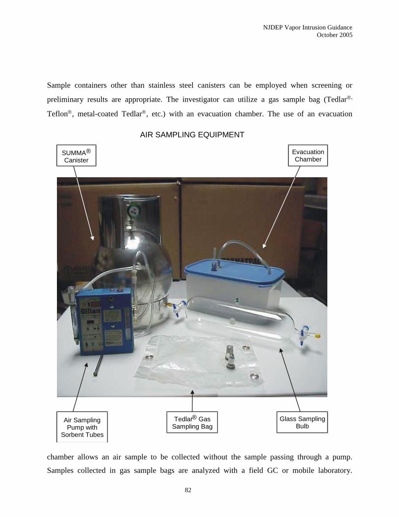
NJDEP Vapor Intrusion Guidance
October 2005
82
Sample containers other than stainless steel canisters can be employed when screening or
preliminary results are appropriate. The investigator can utilize a gas sample bag (Tedlar,
Teflon, metal-coated Tedlar, etc.) with an evacuation chamber. The use of an evacuation
chamber allows an air sample to be collected without the sample passing through a pump.
Samples collected in gas sample bags are analyzed with a field GC or mobile laboratory.
Tedlar® GasSampling Bag
EvacuationChamber
SUMMA®
Canister
Glass SamplingBulb
Air SamplingPump with
Sorbent Tubes
AIR SAMPLING EQUIPMENT
NJDEP Vapor Intrusion Guidance
October 2005
83
Consistent with the NJDEP Field Sampling Procedures Manual (2005), the holding time for
Tedlar bags should not exceed 3 hours.
Alternately, syringes can be used to withdraw a soil gas sample from a probe and then the sample
is immediately injected directly into an analytical instrument for onsite analysis. Syringes come
in varying volumes, materials of construction and designs to meet the analytical criteria. Syringe
samples should be analyzed with a field GC or mobile laboratory and they have a short holding
time (minutes).
A less common sample container is a glass cylinder or sampling bulb which has openings at each
end and with a septum port to withdraw sample aliquots with a syringe. The air sample is
collected by connecting one end of the bulb to the probe and the other to a pump. Sample
holding times for the glass bulbs is 24 hours (NJDEP, 2005).
The analytical method used for the alternative sample containers is not stipulated in this
guidance. However, USEPA SW-846 Method 8260B is the most common method utilized for
field screening of soil gas samples.
If the purpose of the near slab soil gas sampling is as a stand-alone assessment of the VI
pathway, a certified laboratory must be employed. At this time, that would require the use of 1-
Liter or 6-Liter canister samples analyzed with USEPA Method TO-15.
The Department may entertain the utilization of a mobile laboratory certified in an appropriate
air method as a stand-alone assessment. However, detection limits shall meet the NJDEP SGSL.
In addition, 10% of the air samples should be collected as duplicates using stainless steel
canisters and analyzed at a fixed laboratory for USEPA Method TO-15. The duplicate samples
should be collected from locations containing a range of volatile concentrations.
The initial rounds of soil gas samples should be analyzed for the full suite of volatiles based on
the approved method. Subsequent phases of soil gas sampling can employ a reduced parameter
list as part of an approved VI investigation workplan.
NJDEP Vapor Intrusion Guidance
October 2005
84
6.3.2.5 Purge Volumes
Prior to attaching the sample container, the vapor probe should be purged by drawing 3.0
volumes of air through the probe and connecting tubing. The volume is calculated as follows:
hrePurgeVolum 20.3
where r is the inner radius of the probe and connecting tubing, and h is the length of the probe
and connecting tubing. The investigator should use a low purge rate at a maximum of 200 ml per
minute (based on professional judgment).
Alternately, the vapor probe or soil gas well can be purged until field-screening parameters are
stabilized. This approach typically employs 3-Liter Tedlar bags and a lung box to collect the
purged air samples, which are then analyzed for O2, CO2, and PID/FID readings. The
investigator should avoid excessive purging of the subsurface environment.
6.3.2.6 Sample Flow Rate
When a gas sample bag or syringe is utilized in combination with a field GC or mobile
laboratory, the length of time for sample collection should be a maximum of 200 milliliters per
minute (based on the professional judgment of the investigator). Care should be taken to avoid
short circuiting or drawing in outside air along preferential pathways. Thus, instantaneous or
grab samples are not acceptable due to the increased possibility of short circuiting leading to an
invalid sample.
For stainless steel canisters, the sample flow rate should be a maximum of 200 milliliters per
minute, which corresponds to a sample time of 5 minutes for 1-Liter canisters. This maximum
flow rate has been established due to the larger volume of stainless steel canisters and the
concern over short-circuiting.
The certified laboratory provides stainless steel canisters with pre-set regulators (based on the
sample time prescribed by the investigator). Therefore, the sample time must be established in
NJDEP Vapor Intrusion Guidance
October 2005
85
advance of the sampling event. Investigators can determine a draw rate prior to the soil gas
sampling event through the installation of a test probe and subsequent draw rate determination
with a purge pump.
6.3.2.7 Sample Locations
If near slab soil gas samples are being collected as a stand-alone assessment of the VI pathway,
samples should be collected from at least two sides of the building in question. Precise locations
will be in part dictated by the existing conditions around the building perimeter (e.g., other
structures, landscaping, access issues) and the precise location of the ground water plume. The
VI investigation workplan shall identify specific sample locations and provide technical
justification for their selection.
Conversely, if the purpose of the soil gas sampling event is for any other purpose including field
screening, the sample locations should be determined based on the end use of the data. The VI
investigation workplan should define the goal of the soil gas sampling approach and how the
proposed locations meet that need.
6.3.2.8 Number of Samples
In general, the number of samples recommended for the VI investigation is dictated by the
sample spacing necessary. Samples should be spaced horizontally at a minimum of two to three
times the depth to ground water. For a typical single family dwelling of 1,500 ft2, one sample on
each of two sides would be a minimum number of near slab soil gas samples. However, larger
multi-family residential units and commercial, industrial or retail buildings may require
additional samples spaced equidistant from each other (consistent with the depth to water table
rule above).
If two soil gas sample locations have two to three orders of magnitude difference in
concentration, at least one sample should be collected between the two points. Reducing the
sample intervals below this distance across a site will not necessarily provide for better
NJDEP Vapor Intrusion Guidance
October 2005
86
resolution of contamination. It may only indicate the variability in the soil horizon rather than
changes in volatile concentrations. Soil gas sampling is not a high resolution technique for
contamination delineation and should not be used for this type of interpretation (NJDEP Field
Sampling Procedures Manual 2005).
Any decision on the number of soil gas sample points should start with an evaluation of the
CSM. If there are indications from the ground water characterization that there could be large
lateral changes in concentrations over short distances near a structure, there may be a case for
increasing the number of sample points.
6.3.2.9 Sample Frequency
As discussed in Chapter 6.6 (Indoor Air Sampling Procedures), seasonal variability in vapor
concentrations necessitates (in most circumstances) collecting more than one round of indoor air
samples. Similar variability is not apparent in soil gas samples. However, if near slab soil gas
samples are being collected as a stand-alone determination of the VI pathway, a second
confirmation sample may be necessary.
The Department recommends the collection of sub-slab soil gas samples whenever indoor air
samples are obtained. Therefore, multiple rounds of sub-slab soil gas samples may be dictated by
the sampling requirements of indoor air. For indoor air, one of the two sampling events should
take place during the months between November and March, since these are generally “worst
case” conditions for VI (see Chapter 6.6, Indoor Air Sampling Procedures).
In situations where near slab or exterior soil gas sampling is being done to evaluate contaminant
patterns or assess background contamination, a decision on the frequency of sampling should be
determined on a site-specific basis.
6.3.2.10 Underground Utilities
Many accidents in subsurface investigations are due to encountering subsurface utilities. Prior to
mobilizing for any soil gas investigation, health and safety concerns must be answered. Of
NJDEP Vapor Intrusion Guidance
October 2005
87
greatest concern would be to locate any underground utilities. NJ One Call is a free service and
can be contacted at 1-800-272-1000 (out of State call 908-232-1232). They will contact all utility
companies that may have services in the area of investigation. Calls must not be made less than 3
full working days and not more than 10 working days prior to the planned work. If work is
delayed past the 10 days, you are required to renew your ticket. “One Call” legislation mandates
that all owners of underground infrastructures become New Jersey One Call members.
6.3.2.11 License Requirements
The license requirement for performing a soil gas survey is for the installation of the soil gas
probes used for the collection of a soil gas sample. The requirement is based on depth and
diameter of the boring and the length of time a probe will remain in the hole. Please consult
N.J.A.C. 7:9D-Well Construction; Maintenance and Sealing of Abandoned Wells for further
information. A copy is available through the Bureau of Water Allocation 609-984-6831.
6.3.2.12 Passive Sample Collection Methodologies
According to the NJDEP Field Sampling Procedures Manual (NJDEP 2005), Passive sample
collection includes two general sample collection techniques. These techniques include the
passive collection of contaminants onto sorbent material placed in the vadose zone and a whole
air passive collection technique for collecting vapors emissions from the soil surface using an
emission isolation flux chamber.
Passive sorbent sample collection utilizes diffusion and adsorption for soil gas collection onto a
sorbent collection device over time. The soil gas data will delineate the nature and extent of
subsurface contamination. The soil gas data at one location can be compared relative to the soil
gas data from other sample locations in the survey. The mass levels will show patterns of the
spatial distribution indicating areas of greatest subsurface impact. These areas can then be
targeted for further investigation.
Since the passive sorbent samplers provide results in mass concentration, their use is limited to
field screening only during the investigation of the VI pathway.
NJDEP Vapor Intrusion Guidance
October 2005
88
The flux chamber is an enclosure device used to sample gaseous emissions from a defined
surface area. These data can be used to develop emission rates for a given source for predictive
modeling of population exposure assessments. The data can also be used to develop emission
factors for remedial action designs.
The emission isolation flux chamber is a dome superimposed on a cylinder. This shape provides
efficient mixing since no corners are present and thereby minimizing dead spaces. Clean dry
sweep air is added to the chamber at a controlled volumetric flow rate. The gaseous emissions
are swept through the exit port where the concentration is monitored by a real time or discrete
analyzer. Real time measurements are typically performed with portable survey instruments to
determine relative measurements of flux chamber steady state operation and hot zones. Discrete
samples are taken when absolute measurements are required for steady state concentrations and
emission rate levels. The emission rate is calculated based upon the surface area isolated, sweep
airflow rate, and the gas concentration. An estimated average emission rate for the source area is
calculated based upon statistical or biased sampling of a defined total area.
The approval to utilize flux chamber sampling should be requested from the Department in
advance of the sampling event as part of a Site-Specific Assessment (Stage 6). Justification
should be provided to the Department as to why the emission isolation flux chamber method is
more appropriate for this particular phase of the investigation.
6.3.2.13 Undeveloped Parcels and Future Use
When the potential for VI extends to undeveloped parcels, a VI investigation must be
implemented to assess the impact on future use. A generic approach to investigating an
undeveloped parcel would be conducting soil gas sampling on a 100-foot grid at a minimum
depth of 5 feet. This grid method is approximately equal to the average New Jersey residential
housing tract of ¼ acres. In situations where the future use is restricted by an institutional
control, an alternative approach may be proposed, possibly postponing investigation to some
point in the future when development is being considered.
NJDEP Vapor Intrusion Guidance
October 2005
89
6.3.2.14 Data Evaluation
Near slab soil gas results are generally utilized for comparison to other data sets (e.g., ground
water, indoor air, and ambient air). For the most part, these data allow the investigator to
determine patterns in the results and differentiate site-related compounds from other potential
sources. Like sub-slab results, near slab soil gas data can be compared to the NJDEP SGSL.
6.4 Sub-Slab Soil Gas Sampling Procedures
The collection of sub-slab soil gas is an effective investigative tool when assessing the VI
pathway. The procedure involves drilling through the building’s concrete slab and collecting a
soil gas sample for field or laboratory analysis. Sub-slab soil gas samples are often collected
concurrently with indoor air samples to assess VI and potential background contaminant sources.
In situations where an earthen floor exists (instead of concrete), the provisions for sub-slab soil
gas sampling may not be appropriate. Structures are often built with partial or full crawl spaces
that extend the entire building footprint and utilize gravel or dirt. In other situations, the
basement may be unfinished without a concrete floor. As a general rule, sub-slab soil gas
sampling should be employed when the basement slab covers 50% or more of the building
footprint. In these situations, it may be prudent to collect a combination of sub-slab soil gas
samples from the concrete area and indoor air samples from the crawl space.
It is also important to understand the differences between sub-slab and exterior soil gas
sampling. Sub-slab refers to soil gas samples collected from below a slab (typically in the
basement of a building). Exterior, on the other hand, involves collecting soil gas samples from
below the ground surface outside of a structure, utilizing a Geoprobe or slam bar. The soil gas
samples collected from the earthen areas should be collected according to the procedures for near
slab or exterior soil gas sampling found in Chapter 6.3 (Exterior and Near Slab Soil Gas
Sampling Procedures).
NJDEP Vapor Intrusion Guidance
October 2005
90
The utilization of sub-slab soil gas sampling is also questionable when a high water table exists
near the base of the sub-floor (less than 2 feet). Typically, vapors migrate through the most
coarse and/or driest material. Depending on the analytical method, high moisture content in the
soil gas sample can “mask” results, particularly polar compounds. Additionally, reduced
permeability of the soil in the capillary fringe area may limit the movement of soil gas.
Specifically, sub-slab soil gas samples can be collected when ground water is as close as two feet
below the building foundation if:
1) The seasonal high water table does not reach the building foundation; and
2) The water table does not extend into fill material directly under the building
foundation; and
3) The capillary zone does not reach the building foundation.
The Department may be consulted for additional information in these situations.
6.4.1 Application
Sub-slab soil gas sampling can be useful to an environmental investigator from several
perspectives.
6.4.1.1 Stand-Alone Assessment of the VI Pathway
Under the right circumstances, the results of sub-slab soil gas sampling may be utilized to
determine whether the VI pathway is currently complete for a particular building. This is
appropriate when the source of the vapors is a contaminated ground water plume under or in
close proximity to the building in question. Investigators may want to collect sub-slab soil gas
samples as an alternative to indoor air sampling in situations where indoor sources are likely to
significantly affect indoor air quality.
While the Department recognizes the role of sub-slab soil gas sampling in assessing the VI
pathway, there are a number of factors that have to be considered when utilizing these data. Sub-

NJDEP Vapor Intrusion Guidance
October 2005
91
slab soil gas is not as likely to be definitive when the vapor source is solely subsurface
contaminated soil (vadose zone). For example, there may be situations where vapors migrate
laterally and do not collect under the building’s slab (depending on the building construction, the
depth of the soil contamination, and the slab’s depth below the surface). In addition, preferential
pathways, such as utility trenches, allow horizontal movement of the vapors. In these cases,
infiltration of vapors through openings in the sidewalls of a basement may represent the primary
pathway for VI. As a result, sub-slab soil gas results may be low or marginal, while indoor air
data can still exceed health-based levels. Under these conditions, near slab soil gas samples
collected between the zone of soil contamination and the structure’s foundation may be more
appropriate than sub-slab samples.
It is important to understand the stratigraphy in the area of the building. Low permeability layers
under buildings (either natural or as part of construction) may act as an impediment to significant
vertical vapor migration from the ground water contamination. The presence of such a layer may
explain why relatively clean sub-slab samples can occur even though underlying ground water is
contaminated. However, vapors may still enter the building through utility trenches or other
preferential pathways if they bisect or circumvent the low permeability layer.
The presence of elevated contaminant vapors in the sub-slab soil gas is generally a positive
indicator of VI when applying an attenuation factor (discussed below). However, the reverse
circumstances (low contaminated levels in the sub-slab soil gas) do not automatically imply that
the vapor pathway is incomplete. Site-specific conditions, such as distance from any vadose zone
sources and depth of those sources (see the CSM section) should be evaluated before reaching
any conclusions on the VI pathway.
6.4.1.2 Evaluating Contaminant Patterns
Analytical data from sub-slab soil gas samples should be assessed to identify any patterns in
particular chemicals, groups of chemicals and/or their concentrations (both individually and
collectively). When combined with data from other matrices (e.g., ground water, indoor air, and
ambient air), these patterns may assist in distinguishing likely sources of indoor air contaminants

NJDEP Vapor Intrusion Guidance
October 2005
92
and their pathways. For a further discussion on this topic, see Chapter 7, Evaluation of Analytical
Results and Risk.
In addition, the investigator may want to evaluate the vertical depth profile of the contaminated
soil gas. Vertical profiling is considered a site-specific procedure (see Chapter 5 for more
information).
6.4.1.3 Assessing Background Contamination
One specific area where sub-slab soil gas results are particularly useful is in the differentiation of
background contamination in indoor air. By comparing the specific chemicals (and their
concentrations) detected in the indoor air sample with the sub-slab soil gas sample, a
determination may be possible on the likely role of background sources. In addition, the end user
should consider the horizontal movement of vapors as a potential contributor to the indoor air
quality (as discussed in Section 6.4.1.1, above).
6.4.2 Sampling Procedure
Two different basic procedures for sub-slab soil gas sampling are provided below.
The first method employs a permanent sample point with stainless steel tubing and fittings. This
method is recommended for long term monitoring of sub-slab soil gas as part of a remedial
action. The approved Remedial Action Workplan shall include a VI monitoring plan to assess the
changing concentration of contaminants of concern over time. Any decision to terminate a
remedial action involving VI will most likely be made in part based on the sub-slab soil gas
results.
The second procedure utilizes Teflon, metal (or similar) tubing for a temporary sample point.
This method is more appropriate during the initial phases of investigation when the VI pathway
is being evaluated. However, the investigator may want to use permanent sample points as part
of the remedial investigation.
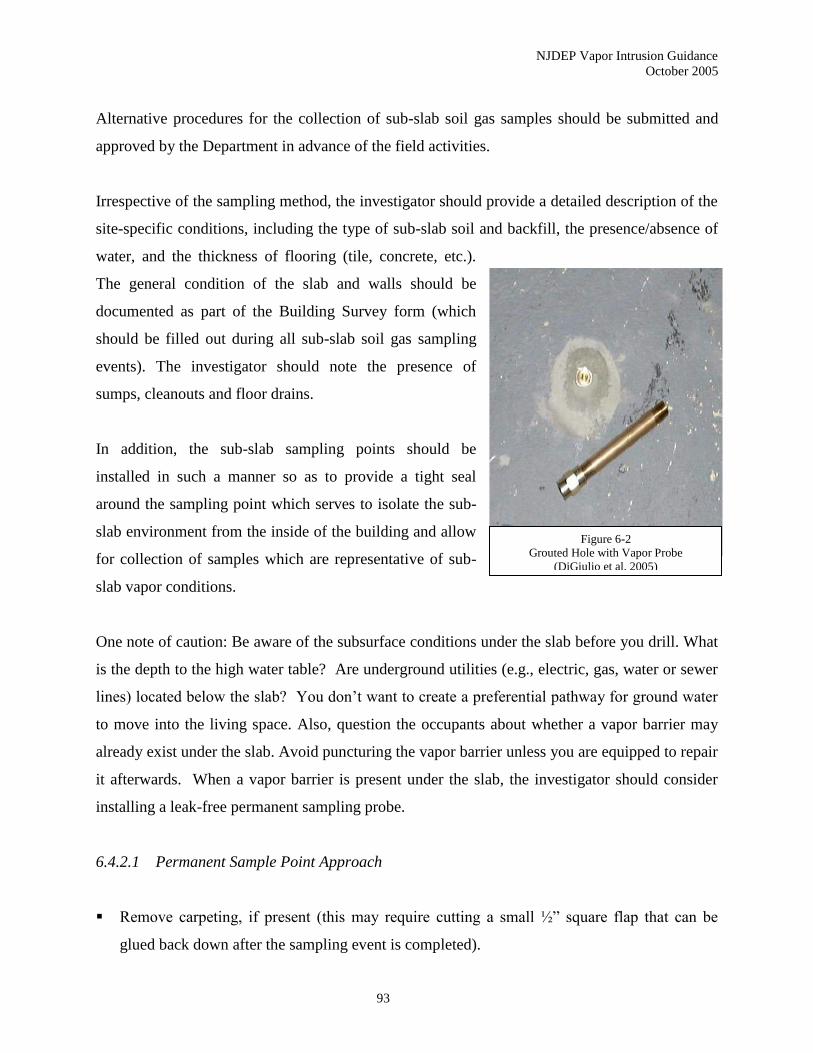
NJDEP Vapor Intrusion Guidance
October 2005
93
Alternative procedures for the collection of sub-slab soil gas samples should be submitted and
approved by the Department in advance of the field activities.
Irrespective of the sampling method, the investigator should provide a detailed description of the
site-specific conditions, including the type of sub-slab soil and backfill, the presence/absence of
water, and the thickness of flooring (tile, concrete, etc.).
The general condition of the slab and walls should be
documented as part of the Building Survey form (which
should be filled out during all sub-slab soil gas sampling
events). The investigator should note the presence of
sumps, cleanouts and floor drains.
In addition, the sub-slab sampling points should be
installed in such a manner so as to provide a tight seal
around the sampling point which serves to isolate the sub-
slab environment from the inside of the building and allow
for collection of samples which are representative of sub-
slab vapor conditions.
One note of caution: Be aware of the subsurface conditions under the slab before you drill. What
is the depth to the high water table? Are underground utilities (e.g., electric, gas, water or sewer
lines) located below the slab? You don’t want to create a preferential pathway for ground water
to move into the living space. Also, question the occupants about whether a vapor barrier may
already exist under the slab. Avoid puncturing the vapor barrier unless you are equipped to repair
it afterwards. When a vapor barrier is present under the slab, the investigator should consider
installing a leak-free permanent sampling probe.
6.4.2.1 Permanent Sample Point Approach
▪ Remove carpeting, if present (this may require cutting a small ½” square flap that can be
glued back down after the sampling event is completed).
Figure 6-2
Grouted Hole with Vapor Probe
(DiGiulio et al. 2005)

NJDEP Vapor Intrusion Guidance
October 2005
94
▪ Drill a 3/8” diameter hole through the concrete slab using an electric drill.
▪ Advance the drill bit approximately 3” into the subslab material (gravel or soil) to create an
open cavity.
▪ Overdrill the top 1” (vertical) of the probe hole to a diameter of 1”.
▪ Insert the vapor probe flush with the top of the concrete slab and add a non-volatile emitting
surface sealing material (e.g., portland cement) to seal the annular space.
▪ Allow the test points to cure for at least 1 hour (portland cement will likely take longer).
▪ Connect the vapor probe to a “T” fitting made of a stainless steel flexible line (or similar
inert material) and an in-line valve.
▪ Purge the vapor probes and sampling lines (see discussion below on purge volumes).
▪ Close valve on the vacuum pump line.
▪ Open the valve to collect a sub-slab soil gas sample.
A typical vapor probe is constructed from small diameter (e.g., 0.64 cm or ¼ in OD x 0.46 cm or
0.18 in ID) chromatography grade 316 stainless steel tubing and stainless steel compression to
thread fittings (e.g., 0.64 cm or ¼ in OD x 0.32 cm or ⅛ in NPT Swagelok female thread
connectors) (DiGiulio et al. 2005). It is imperative that the vapor probe is completed flush with
the concrete surface to avoid problems for the occupants of the building. It should be noted that
the dimensions of the vapor probe and the corresponding hole, as well as the materials utilized in
the sampling apparatus, are guides and are not suppose to be prescriptive. Minor modifications
may be appropriate. Alternative methods
utilizing established protocols (e.g.,
ASTM) may be considered.
Ideally, the vapor probes should remain
in the concrete slab beyond their initial
use. It may be necessary to collect
additional rounds of sub-slab soil gas to
properly assess the VI pathway.
Furthermore, the vapor probes may assist
with any potential remedial actions

NJDEP Vapor Intrusion Guidance
October 2005
95
involving sub-slab depressurization systems. The building owners should be encouraged to allow
the vapor probes to remain in place for the foreseeable future.
6.4.2.2 Temporary Sample Point Approach
Depending on the particular circumstances (e.g., occupant’s preferences, early investigative
phase, and urgency of sample collection), a temporary or less permanent probe may be utilized.
Instead of the stainless steel tubing and fittings, 1/8 to 3/8 in tubing (Teflon, nylaflow, metal or
similar materials) may be substituted. The tubing should be wrapped with Teflon tape to create a
snug fit when the tubing is twisted into the hole. The drill hole should be smooth wall to
minimize potential for leaks. Modeling clay, beeswax or other non-volatile emitting and non-
shrinking materials may be utilized.
The objective with a temporary sample point is to use tubing that is only slightly smaller in
diameter than the drill hole. Do NOT overdrill the top 1” (vertical) of the probe hole – as with a
permanent sample point. Since portland cement is not being used, the sample points can be set up
the same day as the sub-slab soil gas sampling (Hers and Rees 2005). Purging and sample
collection (with a stainless steel canister) should be conducted similarly to the permanent sample
point procedures above.
6.4.2.3 Sample Containers and Analytical Methods
The primary sample container recommended for the collection of sub-slab soil gas samples is
stainless steel canisters. Either 1-Liter or 6-Liter canisters may be employed. The sub-slab soil
gas samples should be analyzed using USEPA Method TO-15 (or other appropriate certified
methods).
Sample containers other than stainless steel canisters can be employed when screening or
preliminary results are appropriate. The investigator can utilize a Tedlar bag for sample
collection and analyze the samples with a field GC or mobile laboratory. Alternately, a 60 - 500
cubic centimeter (cc) syringe can be used. As with the Tedlar bags, syringe samples should be
NJDEP Vapor Intrusion Guidance
October 2005
96
analyzed with a field GC or mobile laboratory. It should be noted that the holding time for Tedlar
bags should not exceed 3 hours.
The analytical method used for the alternative sample containers is not stipulated in this
guidance. However, USEPA SW-846 Method 8260B is the most common method utilized for
field screening of air samples.
If the purpose of the sub-slab soil gas sampling is as a stand-alone assessment of the VI pathway,
a certified laboratory using USEPA Method TO-15 or TO-17 must be employed.
6.4.2.4 Sample Flow Rate
When a Tedlar bag or syringe is utilized in combination with a field GC or mobile laboratory, the
length of time for sample collection should be a maximum of 200 milliliters per minute (based
on the professional judgment of the investigator). Care should be taken to avoid short circuiting
or drawing in outside air along preferential pathways. In addition, a proper seal between the
sample point and slab must be established to prevent indoor air from mixing with the soil gas
sample. For these reasons, instantaneous or grab samples are not acceptable.
For stainless steel canisters, the sample flow rate should be a maximum of 200 milliliters per
minute, which corresponds to a sample time of 5 minutes for 1-Liter canisters. This maximum
flow rate has been established due to the larger volume of stainless steel canisters and the
concern over short circuiting. The investigator may want to collect the sub-slab soil gas sample
over a 24 hour period, especially when indoor air samples are being done concurrently.
However, samples times up to 24 hours are acceptable (excluding instantaneous or grab
samples).
The certified laboratory provides 6-Liter stainless steel canisters with pre-set regulators (based
on the sample time prescribed by the investigator). Therefore, the sample time must be
established in advance of the sampling event. Investigators can determine a draw rate prior to the
sub-slab soil gas sampling event through the installation of a test probe and subsequent draw rate
determination with a purge pump.
NJDEP Vapor Intrusion Guidance
October 2005
97
6.4.2.5 Calculating Purge Volumes
Prior to attaching the sample container, the vapor probe should be purged by drawing 3.0
volumes through the probe and connecting tubing. The volume is calculated as follows:
hrePurgeVolum 20.3
where r is the inner radius of the probe and connecting tubing, and h is the length of the probe
and connecting tubing. The investigator should use a low purge rate with a maximum of 200-ml
per minute.
6.4.2.6 Sample Location
Vapor probes should be installed in a central location on the slab. Positions near the perimeter of
the slab are subject to dilution and should be avoided. The selected location(s) should be chosen
in consultation with the property owner. To minimize potential damage to flooring, it may be
necessary to select a location in a closet or utility room (where carpeting or tiles are less visible
or not present at all).
6.4.2.7 Number of Sample Points
The number of sub-slab samples collected is directly related to the goal of the investigation. For
a typical single family residential dwelling (approximately 1500 ft2), one vapor probe installed
near the center of the slab should adequately document the chemical composition of the sub-slab
soil gas. Significantly larger dwellings (or other unique conditions in the subfloor or construction
of the foundation) will require additional vapor probes.
Multi-family residential units and commercial or retail buildings will require a more careful
review of the building features. Consideration should be given when the building has more than
one tenant. Subsurface structures may be present that would facilitate VI and thus degrade indoor
NJDEP Vapor Intrusion Guidance
October 2005
98
air quality in one portion of the building and not another. Any sampling approach should take
into account the different exposure scenarios (e.g., day care, medical facilities) that exist within
the building and any sensitive populations that may be exposed to the contaminated vapors.
Multiple vapor probes are necessary for multi-family residential units and commercial or retail
buildings. The number and placement of those test points should be determined on a site-specific
basis with deliberation given to occupied spaces, segmented areas within larger areas, and
potential future use.
Any decision on the number of sub-slab sample points should start with an evaluation of the
CSM. If there are indications from the ground water characterization that there could be large
lateral changes in concentrations over short distances near a structure, there may be a case for
multiple sample points or targeting the worst case areas.
6.4.2.8 Sample Frequency
If sub-slab soil gas samples are being collected as a stand-alone determination of the VI pathway,
a second confirmation sample may be necessary. Supplemental environmental data (e.g., ground
water, indoor air, or near slab soil gas data) may eliminate the need for a second round of sub-
slab soil gas sampling. In addition, the Department may accept a single round of sampling in
those cases where the analytical results are an order of magnitude below the appropriate
screening level.
In situations where sub-slab soil gas sampling is being done to evaluate contaminant patterns or
assess background contamination, a decision on the frequency of sampling should be determined
on a site-specific basis.
6.4.3 Data Evaluation
Sub-slab soil gas results are generally utilized for comparison to other data sets (e.g., ground
water, indoor air, and ambient air). For the most part, these data allow the investigator to
determine patterns in the results and differentiate site related compounds from other potential
NJDEP Vapor Intrusion Guidance
October 2005
99
sources. Results from a sub-slab soil gas investigation should be compared to the NJDEP SGSL.
These values were generated from the NJDEP IASL by utilizing an attenuation factor of 0.02.
While this factor can be used for a generic screening, a more site-specific evaluation may be
appropriate, especially for petroleum hydrocarbon compounds.
For crawl space air samples, the Department has determined that an attenuation factor of 1.0 is
applicable, consistent with the USEPA (2002b). Therefore, crawl space indoor air samples can
be compared directly to the IASL.
6.5 Conducting A Building Walkthrough and Survey
Preparation is an important aspect for any VI investigation. However, when indoor air samples
are going to be collected as part of the investigation, preparation takes on a new level of
importance.
A building walkthrough is a critical element of any VI investigation workplan that includes
indoor air and/or sub-slab soil gas sampling as an investigative tool. There are several
components of a building walkthrough that should be addressed:
▪ Detection of potential background sources of volatile organic compounds.
▪ Determination of the building construction
▪ Recognition of points of VI in a structure
▪ Identification of possible sample locations
▪ Education of the occupants on VI and sampling procedures
Ideally, the building walkthrough should be conducted at least one week before the actual indoor
air or sub-slab soil gas sampling event. This advance timeframe allows the investigator to
identify and eliminate (to the extent practical) potential background sources of indoor air
contamination. It also permits the investigator to confirm the sample locations with the occupants
and NJDEP ahead of the scheduled sampling episode.
NJDEP Vapor Intrusion Guidance
October 2005
100
6.5.1 Detection of Potential Background Sources
As discussed in Chapter 8, investigating the VI pathway is greatly complicated by the impact of
background contaminant sources. Differentiating the common household sources of poor indoor
air quality from those associated with contaminated ground water or subsurface soil is a legal
and fiscal dilemma facing both regulatory agencies and potential responsible parties throughout
the country.
One of the tools that the Department utilizes in identifying background sources in the indoor air
environment is the Indoor Air Building Survey and Sampling Form (Appendix B). The survey
form allows the investigator to document various information on the building, the occupants, and
potential sources of indoor air contamination. The questionnaire was originally developed by
NJDEP in 1997 and has since been revised for this guidance document using several similar
survey forms prepared by New Hampshire Department of Environmental Services, New York
State Department of Health, Vermont Department of Health, and Massachusetts Department of
Environmental Protection.
The Indoor Air Building Survey and Sampling Form is broken down into eight sections:
▪ Part I - Basic information on the Occupants of the building, including address,
contact’s name and phone number, owner’s name (if different), and a breakdown of
the occupant’s ages.
▪ Part II - The Building Characteristics of the structure under investigation, including
building and foundation type, number of floors, heating and ventilation systems, fuel
utilized in the building, and the presence/absence of septic systems, sumps,
irrigation/private wells, or existing subsurface depressurization systems.
▪ Part III - Identification of any Outside Contaminant Sources that may exist near the
structure being investigated.
▪ Part IV - Identification of all potential Indoor Contaminant Sources found in the
building, the location of the source, and whether the item was removed from the
building prior to the indoor air or sub-slab soil gas sampling event. This section also
documents remodeling activities, including painting, new carpeting or flooring, and
NJDEP Vapor Intrusion Guidance
October 2005
101
new furniture. It may be necessary to include additional sheets to inventory all the
household products stored within the structure.
▪ Part V - Survey of Miscellaneous Items related to household activities that may
impact indoor air quality, including smoking, dry cleaning clothes, and applying
pesticides on the property.
▪ Part VI - Documentation of Sampling Information, including sample numbers and
locations, start time and end times for the sampling event, and the name of the sample
technician. This section will be completed on the date of the sampling event.
▪ Part VII - Existing Weather Conditions during the sampling event should be
documented on the survey form. As noted in Chapter 2, weather conditions
(especially temperature, barometric pressure, and precipitation) can affect the sample
collection and interpretation of the data.
▪ Part VIII - This section allows the technician to document any General Observations
noted during the sampling event that do not fit into the categories noted above.
Another essential tool for pinpointing background sources of indoor air contaminants is the use
of handheld field screening instruments. Field portable instrumentation provides useful
information for critical decisions in the field. Almost all projects require screening or semi-
quantitative data collection during the field-screening phase of the site investigation. These
instruments are hand held, rugged, and offer rapid results in the field (NJDEP 2005).
For the purpose of a VI investigation, one of the most important factors in selecting the
appropriate field screening instrument is its method detection limits (MDLs). Preferably, the
MDLs should be below the action level or levels of concern (NJDEP IASL) for the indoor air.
Recent advances have been made in the development of field portable instrumentation. Photo-
ionization detectors (PID) are now providing parts per billion (ppb) detection, making them
appropriate for building walkthroughs and surveys during VI investigations. With a ppb
detecting PID, individual cans of solvents can be identified as vapor sources and removed from
the building in advance of the sampling event.
NJDEP Vapor Intrusion Guidance
October 2005
102
When household or background sources of indoor air contamination are identified and removed
from a building, it may be necessary to ventilate the rooms affected in advance of the air
sampling event. This ventilation should be completed at least 24 hours before the
commencement of the indoor air sampling event.
6.5.2 Recognition of Points of Vapor Intrusion in a Structure
The entry of organic vapors into a structure is due to the infiltration of contaminants through the
floor and walls that are in contact with the soil. Usually, vapors enter a building through poorly
sealed utility lines that penetrate the foundation. Other contaminant pathways are through cracks
in the walls and floors, sumps, around the wall/floor juncture of floating floor construction or
other breaches in the walls or slab.
The Indoor Air Building Survey and Sampling Form asks a series of questions that are designed
to assist in the identification of potential points of VI. Part II inquires about the type of building
foundation, construction of the basement floor, and the presence of sumps. Any obvious breaches
in the walls or slab in the basement (or lowest floor) should be noted in Part VIII (General
Observations) of the Indoor Air Building Survey and Sampling Form. The investigator should
also examine the point at which all utility lines enter the structure.
6.5.3 Identification of Possible Sample Locations
The building walkthrough is a perfect time for the investigator to identify possible sample
locations that fit the defined investigative goals of the VI investigation workplan.
Sub-slab soil gas samples should be collected from a central location on the slab. Positions near
the perimeter of the slab are subject to dilution and should be avoided. To minimize potential
damage to flooring, it may be necessary to select a location in a closet or utility room (where
carpeting or tiles are less visible or not present at all). The selected location(s) should be chosen
in consultation with the property owner during the building walkthrough.
NJDEP Vapor Intrusion Guidance
October 2005
103
Indoor air samples are generally collected from more than one floor within a structure to address
varying risk exposures and as part of the process to distinguish contaminants related to VI from
background sources. Thus, the location and position of the sample container will vary depending
on which floor the sampling event takes place.
Ground floor (living space) samples should be located to approximate human risk exposure.
Thus, these indoor air samples are generally placed at breathing zone height (3-5'). Consideration
should also be given on a case specific basis to those situations (such as a day care facility)
where a different sampling height may also be appropriate to evaluate a unique setting or
population. The basement sample(s) are primarily designed to investigate “worst case” situations
within a structure. Therefore, basement samples are positioned as close as possible to the source
area (e.g., sumps, major cracks in foundation).
Hence, the building walkthrough allows the investigator to identify potential sample locations for
both sub-slab soil gas and indoor air samples. It is recommended that the final locations be
selected in consultation with the department’s technical staff.
6.5.4 Education of the Occupants on Vapor Intrusion and Sampling Procedures
One of the responsibilities of the investigator when collecting samples within a structure is to
educate the occupants on the VI pathway. Unlike other environmental matrices (soil, ground
water, surface water, or sediments), indoor air quality can have an immediate and possible long
term affect on human health that is not easily addressed by simple avoidance of the contaminated
material.
During the building walkthrough, occupants are likely to raise a number of issues that the
investigator should be prepared to answer. Refer to Chapter 11 for a discussion on how to
conduct community outreach during the investigation of the VI pathway. In addition, two fact
sheets, Evaluating Indoor Air near VOC Contaminated Sites (Appendix D) and Subsurface
Depressurization Systems (Appendix E) may provide further assistance.
NJDEP Vapor Intrusion Guidance
October 2005
104
The Department has prepared a one page advisory paper entitled Instructions for Occupants -
Indoor Air Sampling Events (Appendix C). The instructions provide the occupants with a list of
actions that should be avoided before and during the sampling event. The Instructions for
Occupants - Indoor Air Sampling Events sheet should be made available to the occupants at least
one week in advance. The paper can be presented during the building walkthrough (assuming the
timeframe is met). Any deviation from the instructions noted during the sampling event should
be documented on the Indoor Air Building Survey and Sampling Form.
6.6 Indoor Air Sampling Procedures
When compared to the other investigative tools available, indoor air sampling (Stage 4C)
represents the most direct measure of human health exposure for the VI pathway.
Utilization of the J&E model to extrapolate potential vapor concentrations within a structure
based on ground water data can be adversely influenced by numerous geophysical parameters.
Data from sub-slab or near slab soil gas sampling employs an attenuation factor that can
estimate indoor air concentrations resulting from VI. These procedures do not provide actual
analytical data on the indoor air quality. Yet, indoor air sampling is not without its problems.
Indoor air quality is affected by a multitude of sources that originate both inside and outside any
building. Background contamination should be properly assessed whenever indoor air samples
are collected. A detailed discussion on background contamination can be found in Chapter 8. In
addition, a variety of meteorological, temporal, and structural factors can influence indoor air
concentrations resulting from VI (as discussed in Chapter 2).
Despite these shortcomings, the Department recommends the collection of indoor air samples
whenever the potential for VI exists and other investigative tools can not eliminate the pathway.
In addition, indoor air samples are appropriate for remedial confirmation purposes.
NJDEP Vapor Intrusion Guidance
October 2005
105
6.6.1 Application
Analytical results from indoor air sampling events are applicable to the assessment of the VI
pathway in several ways.
6.6.1.1 Stand-Alone assessment of the vapor intrusion pathway
Analytical results from indoor air sampling may be utilized to determine whether the VI pathway
is currently complete for a particular building.
In order for the indoor air results to be acceptable to the Department in any stand-alone
assessment of the VI pathway, all sampling procedures provided in this guidance should be
followed for the collection of indoor air samples.
The Department does not accept averaging of the results of the indoor air samples within a
building. Therefore, each data point should be evaluated independently of each other. Always
refer back to the CSM when evaluating data and making any conclusions on the VI pathway.
6.6.1.2 Evaluating contaminant patterns
Analytical data from indoor air samples collected from different floors within a structure should
be assessed to identify any patterns in particular chemicals, groups of chemicals, and/or their
concentrations (both individually and collectively). When combined with data from other
matrices (e.g., ground water, soil gas, and ambient air), these patterns may assist in
distinguishing likely sources of indoor air contaminants and their pathways. This is important
when background sources located within the structure generate the same volatile organic
compounds identified as contaminants of concern associated with the site investigation. (For a
further discussion on this topic, see Chapter 8.)

NJDEP Vapor Intrusion Guidance
October 2005
106
6.6.1.3 Assessing background contamination
Indoor air samples should be collected concurrently with ambient air and sub-slab soil gas
samples. The analytical results are useful in the differentiation of background contamination in
indoor air. By comparing the site-specific contaminants of concern detected in the soil gas
sample with the indoor air and ambient air results, the investigator can validate the designation of
background contaminants and thus limit any remedial action.
6.6.2 Sampling Procedures and Analytical Methods
Analysis of indoor air samples must utilize a laboratory holding a current
certification/accreditation from NJDEP Office of Quality Assurance (OQA). At present, there are
only two analytical methods where certification is offered - USEPA Method TO-15 and TO-17.
Both of these methods analyze for volatile organic compounds. The Department is investigating
other analytical methods for possible certification that will expand the list of parameters beyond
the standard volatile organics, including naphthalene, formaldehyde, and semivolatile organic
compounds.
The first analytical method - TO-15 - employs stainless steel canisters to collect whole air
samples. Volatile organic compounds (both polar and non-polar) are concentrated on a solid
multisorbent trap, refocused on a second trap, separated
on a gas chromatograph column, and passed to a mass
spectrometer for identification and quantitation. TO-15
is the principal method used for indoor air samples
primarily due to the ease of use for the investigator and
the limited obstruction for the occupants of the building
(compared to other sampling equipment).
TO-17 uses sorbent tubes for the collection of air
samples in the field. There is a large selection of
sorbents that can be matched to the contaminants of
concern. The tubes are thermally desorbed into a gas
Figure 6-4
Autosampler GC/MS for TO-17 analysis (courtesy of Severn Trent Laboratories)

NJDEP Vapor Intrusion Guidance
October 2005
107
chromatogram/mass spectrometer instrument system. The method requires specific collection
procedures and states that after desorption on to the column the samples are to be analyzed in
accordance with USEPA Method TO-15.
Additional information on these two analytical methods can be found in Appendix I, Quality
Assurance Requirements. Alternative methodologies for the collection and analysis of indoor air
samples should be submitted and approved by the Department in advance of the field activities.
Regardless of the analytical method, it is recommended that the investigator complete the
NJDEP Indoor Air Building Survey and Sampling Form (Appendix B). The survey form should
be completed as part of the building walkthrough (conducted prior to the sampling event) and
include information obtained during the actual sampling episode. Similar to the sub-slab
sampling procedures, the general condition of the structure should be documented, including the
presence of sumps, cleanouts and floor drains. Refer to Section 6.5 for additional information on
the building walkthrough and the survey form.
In light of recent events related to homeland security, it is highly recommended that suitable
precautions be taken whenever VI investigations include outside air sampling. The sampling
equipment (e.g., stainless steel canisters) and related devices are not familiar to most individuals
and may be misinterpreted as a safety concern. Therefore, notification about the sampling event
should be provided to the local police and fire departments, in addition to the municipal officials.
It may be necessary to demonstrate the operations of the sampling equipment to these officials. A
label should be affixed to the sampling device explaining the nature of the equipment and all
appropriate contact information in case there are further questions. The individuals collecting the
indoor air samples should be prepared to provide proper identification to the building occupants.
6.6.2.1 TO-15 Requirements
• The sampling event should be conducted by collecting a minimum of one indoor air sample
from the ground floor (living space) at each property using 6-Liter stainless SUMMA
canisters (or other specially prepared stainless steel canisters) and analyzed for VOC using
USEPA Method TO-15. If a basement or crawlspace exists, a second canister air sample
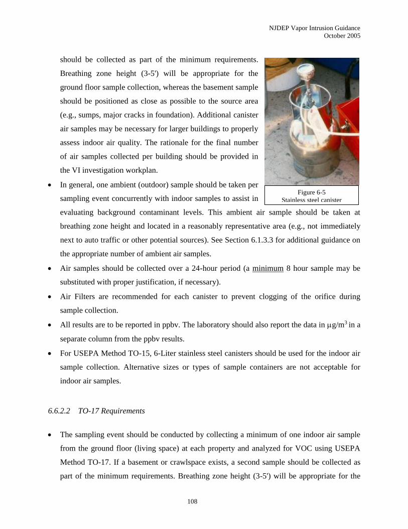
NJDEP Vapor Intrusion Guidance
October 2005
108
should be collected as part of the minimum requirements.
Breathing zone height (3-5') will be appropriate for the
ground floor sample collection, whereas the basement sample
should be positioned as close as possible to the source area
(e.g., sumps, major cracks in foundation). Additional canister
air samples may be necessary for larger buildings to properly
assess indoor air quality. The rationale for the final number
of air samples collected per building should be provided in
the VI investigation workplan.
• In general, one ambient (outdoor) sample should be taken per
sampling event concurrently with indoor samples to assist in
evaluating background contaminant levels. This ambient air sample should be taken at
breathing zone height and located in a reasonably representative area (e.g., not immediately
next to auto traffic or other potential sources). See Section 6.1.3.3 for additional guidance on
the appropriate number of ambient air samples.
• Air samples should be collected over a 24-hour period (a minimum 8 hour sample may be
substituted with proper justification, if necessary).
• Air Filters are recommended for each canister to prevent clogging of the orifice during
sample collection.
• All results are to be reported in ppbv. The laboratory should also report the data in g/m3 in a
separate column from the ppbv results.
• For USEPA Method TO-15, 6-Liter stainless steel canisters should be used for the indoor air
sample collection. Alternative sizes or types of sample containers are not acceptable for
indoor air samples.
6.6.2.2 TO-17 Requirements
• The sampling event should be conducted by collecting a minimum of one indoor air sample
from the ground floor (living space) at each property and analyzed for VOC using USEPA
Method TO-17. If a basement or crawlspace exists, a second sample should be collected as
part of the minimum requirements. Breathing zone height (3-5') will be appropriate for the
Figure 6-5
Stainless steel canister
NJDEP Vapor Intrusion Guidance
October 2005
109
ground floor sample collection, whereas the basement sample should be positioned as close
as possible to the source area (e.g., sumps, major cracks in foundation). Additional air
samples may be necessary for larger buildings to properly assess indoor air quality. The
rationale for the final number of air samples collected per building should be provided in the
VI investigation workplan.
• For each sampling point, the investigator will be required to collect two sorbent tubes for
each sampling point in parallel. The sorbent material in each tube must be the same material.
• In general, one ambient (outdoor) sample should be taken per sampling event concurrently
with indoor samples to assist in evaluating background contaminant levels. This ambient air
sample should be taken at breathing zone height and located in a reasonably representative
area (e.g., not immediately next to auto traffic or other potential sources). See Section 6.1.3.3
for additional guidance on the appropriate number of ambient air samples.
• The pump rate must be set so that the final calculated reporting limit used by the laboratory
shall be less than or equal to 0.5 ppb.
• The minimum sample collection time for the sorbent tubes has been established by NJDEP as
eight (8) hours. A twenty-four (24) hour sample collection time is the preferred sampling
time, since it provides a longer time weighted average for exposure.
• The choice of sampling apparatus and sorbent material is left to the investigator. However,
the apparatus must conform to Section 6.3.1 of Method TO-17, which requires
accommodations for two sampling tubes with the capability of independent control for
sampling rate at a settable value in the range of 10 to 200 ml/min.
• All quality assurance provisions stipulated in Appendix I (Quality Assurance Requirements)
shall be followed for USEPA Method TO-17.
• All results are to be reported in ppbv. The laboratory shall also report the data in g/m3 in a
separate column from the ppbv results.
6.6.2.3 Number of Sample Locations
As previously stated above, a typical single family residential dwelling (approximately 1,500 ft2)
should have one indoor air sample collected from the first floor and one from the basement or
crawl space (if present). Significantly larger dwellings may require additional samples.
NJDEP Vapor Intrusion Guidance
October 2005
110
Multi-family residential units and commercial or retail buildings will require a more careful
review of the building features. Consideration should be given when the building has more than
one tenant. Subsurface structures may be present that would facilitate VI and thus degrade indoor
air quality in one portion of the building and not another. Any sampling approach should take
into account the different exposure scenarios (e.g., day care, medical facilities) that exist within
the building and any sensitive populations that may be exposed to the contaminated vapors.
Multiple indoor air sample locations are necessary for multi-family residential units and
commercial or retail buildings.
6.6.2.4 Sample Frequency
As discussed in Chapter 2, seasonal variability in vapor concentrations necessitates (in most
circumstances) collecting more than one round of indoor air samples.
If indoor air samples are being collected as a stand-alone determination of the VI pathway, a
second confirmation sample may be necessary. One of the two sampling events should take place
during the months between November and March, since these are generally “worst case”
conditions for VI. However, the Department will accept a single round of sampling (irrespective
of the seasonal timing of the sample event) in those cases where the results are an order of
magnitude below the appropriate screening level.
6.6.2.5 Pressure and Temperature Issues
The laboratory prepares the canisters and establishes the flow rate of the regulators based on the
barometric (atmospheric) pressure and temperature inside of the laboratory. The canister pressure
must be set at approximately –30 inches of mercury at the laboratory prior to shipment. Once in
the field, temperature and atmospheric pressure changes that occur over the sample collection
time will affect the rate of sample collection. A sharp decrease in the temperature (from the
temperature at which the regulators are set in the laboratory) during the period of sample
NJDEP Vapor Intrusion Guidance
October 2005
111
collection will increase the flow rate into the canister, while an increase in temperature will slow
the flow rate.
Thus, the Department recommends the collection of ambient temperature and pressure readings
during the collection of all air samples.
For an exterior ambient sample, there are two ways to obtain this information. Atmospheric
pressure and temperature can be acquired from the nearest weather reporting station. Two
websites that may be useful to the investigator are the National Oceanic and Atmospheric
Administration, National Weather Service website at http://www.weather.gov or Weather
Underground at http://www.wunderground.com/. Alternately, the investigator can bring portable
meteorological instrumentation on site to obtain the information real time.
Temperature for interior samples should be obtained using portable meteorological
instrumentation with readings taken inside the structure. For all indoor air samples, individual
temperature readings will be necessary for each sample location. Larger commercial buildings
may also require barometric pressure readings for each sample.
6.6.3 Data Evaluation
Indoor air results are compared to the NJDEP IASL. Ideally, the data will establish patterns in
the contaminant distribution, both within the structure (basement verses first and second floors,
etc.) and outside the structure (ambient verses indoor air concentrations). In addition,
comparisons should also be made between the indoor air results and other data sets (e.g., ground
water, indoor air, and ambient air). For the most part, these data allow the investigator to
determine patterns in the results and differentiate site-related compounds from other potential
sources.
The results of air samples collected within a building’s crawl space should be compared to the
NJDEP IASL.

NJDEP Vapor Intrusion Guidance
October 2005
112
7.0 EVALUATION OF ANALYTICAL RESULTS
Once the data packages have been validated, the investigator should evaluate the analytical
results by comparing the soil gas, ground water, and indoor air results to the appropriate
screening levels.
7.1 Background Sources
One of the most critical steps during a VI investigation is the evaluation of analytical data -
particularly as it relates to source identification. Unlike other pathways, the potential for
background contamination is significant. The investigator should follow the framework for
distinguishing background sources found in Chapter 8.
NJDEP relies on a multiple lines of evidence approach when assessing potential background
sources of indoor air contamination, employing a series of primary and secondary factors. The
primary factors are the identification of site-specific contaminants of concern, collection of sub-
slab soil gas and ambient air data, and the evaluation of the results. The secondary factors
include completion of the Indoor Air Building Survey and Sampling Form, review of indoor air
background databases, and collection of exterior soil gas data. As a general point, remedial
action will not be required when the site-specific ambient air results are in excess of the indoor
air results. In these cases, the Department should assess the validity of the ambient air results.
An assessment of potential background sources should be included in any data evaluation
process.
7.2 Ground Water Samples
Assuming the samples are collected consistent with the procedures and recommendations in
Section 6.2, the data should be compared to the applicable NJDEP GWSL. The exceedance of
these screening levels for any volatile will necessitate further investigation. However, it should
not be assumed that elevated ground water concentrations automatically indicate that
unacceptable levels of vapors are currently entering the structure. If exceedances of GWSL are
NJDEP Vapor Intrusion Guidance
October 2005
113
minor and sporadic, appropriate statistical analytical methods may be considered for data
evaluation.
The ground water data shall be evaluated to determine whether the contaminant plume has been
delineated to the extent needed to assess the VI pathway. If it is determined that the plume has
not been sufficiently delineated, additional ground water samples will be required to complete
the delineation as it pertains to this pathway. All existing buildings that are located within 100
feet horizontally of the shallow plume’s perimeter should be identified. The Department does
utilize a 30-foot distance criterion (both horizontal and vertical) for petroleum related
contamination (see Chapter 9 for further discussions). Depending on the soil type, the presence
of preferential pathways, and/or certain hydrogeologic features, the two distance criteria may
have to be modified. The results of this effort will highlight those structures that will necessitate
further investigation for the VI pathway.
7.3 Vertical Ground Water Contaminant Profile
At sites where a clean water lens is investigated, vertical profiles of volatile levels in ground
water may reveal various patterns that are likely to have different implications for the current and
future risk of vapor intrusion. The following guidelines can be used to interpret the data.
A six foot thick lens of ground water with contaminants below the GWSL can be considered
sufficient justification to conclude the plume is not a source for vapor intrusion in the immediate
vicinity. Additional ground water sampling for a VI investigation should not be required where
such a lens exists unless conditions change, or are expected to change to include any
circumstances that will cause the water table elevation to decrease significantly. However,
ongoing monitoring as part of an approved remedial action may be required.
If a lens between three and six feet thick, not exceeding the GWSL, exists between the vadose
zone and the part of the plume that does exceed GWSL, significant off-gassing into the vadose
zone is unlikely. However, in this situation ongoing, periodic water level and/or ground water
monitoring should be performed to confirm the continuing presence of a “below GWSL lens” of
NJDEP Vapor Intrusion Guidance
October 2005
114
at least 3 feet in thickness. If water level data or other information strongly suggest that a below
GWSL lens at least 3 feet thick is not present throughout the year, additional investigation of the
VI pathway (soil gas and/or indoor air sampling) is recommended. If possible, the additional
investigation should be done during, or immediately after, a time period when a below GWSL
lens was not present.
A below GWSL lens less than 3 feet thick overlying a plume which exceeds the GWSL should
trigger additional investigation of the VI pathway and possibly ongoing ground water
monitoring. Conditions which should be considered in designing the next investigative step
include: types of contaminants present; concentrations of contaminants in the various depth
intervals sampled; and thickness of the below GWSL lens in the vertical profile nearest to the
structure.
7.4 Sub-Slab Soil Gas Samples
The compounds detected in the sub-slab (or near slab, when approved) soil gas results should be
compared with the site-specific contaminants of concern (including degradation products)
identified from the contaminated ground water or soil. The compounds should be similar. If
additional compounds are seen in the soil gas results, a secondary VI source may be present. A
supplemental investigation of the local soils may be warranted.
The analytical results of the sub-slab soil gas samples should be compared to the NJDEP SGSL.
The NJDEP SGSL were prepared using the NJDEP IASL with an attenuation factor of 0.02. The
investigator may propose an alternative attenuation factor consistent with the procedures for a
Site-Specific Screening Process (Stage 6).
If the soil gas results exceed the applicable NJDEP SGSL, additional investigation of the VI
pathway is necessary. Unless the investigator is proposing a site-specific approach that is
acceptable to the Department, indoor air sampling will be necessary.

NJDEP Vapor Intrusion Guidance
October 2005
115
In those situations where the soil gas results do not exceed the NJDEP SGSL but ground water
quality exceeds the generic GWSL, a site-specific determination can potentially be made that no
additional VI investigation is needed. This determination should be based on an accurate CSM
and representative ground water data which indicates:
• that shallow ground water concentrations are unlikely to increase in the future; and,
• other site conditions at the time of sampling (e.g., soil moisture, % oxygen in vadose
zone) are unlikely to change enough to result in higher soil gas volatile levels.
Consideration should be given to whether volatile levels in ground water greatly or only slightly
exceed the GWSL. Also consider whether the ground water plume is still growing, at steady-
state conditions, or in the process of attenuating. In the situation where the ground water plume
is still growing, additional investigation is apt to be necessary. If known, the vertical distribution
of contaminant concentrations in ground water may also be relevant to this decision.
Based on the sampling plan, multiple sub-slab soil gas samples may have to be collected. In
general, the Department does not allow the results of the sub-slab soil gas samples to be
averaged across the subsurface of a building. Therefore, each data point should be evaluated
independently of each other.
7.5 Indoor Air Samples from the Basement
The analytical results of the indoor air samples should be compared to the NJDEP IASL. The
investigator may propose alternative screening levels consistent with the procedures for a Site-
Specific Screening Process.
If the indoor air results exceed the applicable NJDEP IASL, additional investigation of the VI
pathway is necessary to confirm the results. Once confirmed, the investigator should propose an
appropriate remedial action, as discussed in Chapter 10.
Multiple samples collected from different locations on the same floor may identify probable
background sources when combined with a building walkthrough and survey. Compare the
NJDEP Vapor Intrusion Guidance
October 2005
116
locations of suspect consumer products (e.g., paints, thinners) or household activities (e.g.,
hobbies, smoking) with the indoor air sample results. Evaluate whether particular volatile
organic compounds are higher or lower in certain portions of a building and if they correlate with
identified background sources. Additionally, determine if the site-specific contaminants of
concern compare to the indoor air compounds detected in the sample results. The need to collect
multiple indoor air samples from the same level is a site-specific determination based on the
likelihood of significant background sources within a structure.
In addition, compare the analytical results with potential VI routes through the building slab or
foundation (e.g., sumps, utility lines, major cracks). Depending on the ventilation system in the
basement, differences in concentrations of site-specific contaminants of concern between
multiple sample points may be related to their relative position near VI points (and not
background sources).
7.6 Multiple Indoor Air Samples from Different Floors
Ideally, indoor air samples should be collected from at least two separate floors within a
structure, preferably the basement (or lowest floor) and the level immediately above it. In part,
the rationale for this approach is to provide the investigator with analytical results that may assist
in the assessment of potential background contaminant sources. This is critical in situations
where sub-slab soil gas samples are NOT collected.
Compare the results for individual compounds on each floor. In general, the concentrations
should decrease as you move away from the source. Thus, if VI from contaminated ground water
or subsurface soil is the main source, the highest concentrations should be in the basement (or
lowest floor) and decrease as you move up to the first or second floor. Conversely, if the higher
concentrations are found in the upper floors (when compared to the basement results), a
background source unrelated to the site is probably located within the building on the floor with
the highest concentrations. Deviations from this general understanding of vapor movement may
exist in situations where a vertical pathway allows vapors to move quickly from one floor to the
next (e.g., elevator shafts, laundry chutes).
NJDEP Vapor Intrusion Guidance
October 2005
117
The first step in differentiating background contamination during indoor air sampling events is to
identify the site-specific contaminants of concern (based on ground water or subsurface soil
data). When these contaminants of concern are found in potential background sources located
within the building under investigation, results from multiple indoor air samples can be
compared to the relative concentrations of related contaminants.
For example, benzene, ethylbenzene, toluene and xylenes (BTEX) are common contaminants
associated with gasoline. Compare the concentrations of each of these contaminants relative to
each other. Evaluate whether a similar relationship exists between the contaminants detected in
other samples collected either on the same or different floors of the building. If benzene and
toluene generally have a 1:1 ratio in the basement and the 2nd floor samples have 3x as much
toluene as benzene, it is probable that a secondary background source of toluene is located on the
2nd floor (e.g., nail polish).
7.7 Indoor Air and Sub-Slab Soil Gas Samples
The Department recommends that the collection of indoor air and sub-slab soil gas samples be
conducted concurrently during the investigation of the VI pathway. The combination of indoor
air and sub-slab soil gas results will assist in identifying likely background indoor air sources and
verify whether a VI source exists below the building (instead of extrapolating contaminated
ground water or subsurface soil results from indoor air).
The Department has developed a Remediation Decision Matrix (part of the Decision Flow Chart
- Appendix A) to assist the investigator in assessing the VI pathway. Specifically, the
Remediation Decision Matrix evaluates the relationship between the sub-slab soil gas and indoor
air sample results, providing guidance on the appropriate action (e.g., no action, monitoring,
further investigation, and mitigation).
Frequently, contaminants will be found in the indoor air, but not the sub-slab soil gas samples.
The compounds are likely originating from background sources unrelated to VI (especially if
NJDEP Vapor Intrusion Guidance
October 2005
118
they are not site-specific contaminants of concern). In these cases, the Remediation Decision
Matrix directs the investigator to evaluate vadose zone (soil) contamination and preferential
pathways as potential contributors to indoor air contamination that might not be detected in the
subsurface soil gas results. Once it is established that VI is not contributing to the indoor air
contamination, no further action is necessary for this pathway.
The investigator will identify cases where the indoor air concentrations are below the IASL, but
the sub-slab soil gas results are elevated, indicating a potential source in the subsurface. In these
situations, the Remediation Decision Matrix differentiates between elevated sub-slab soil gas
results that are less than or more than 10 times the SGSL.
For sub-slab soil gas results that are 10 times or less the SGSL, the options are no further action
or continued monitoring. The higher the sub-slab soil gas exceedance, the more probable it is
that monitoring will be necessary.
If the sub-slab soil gas results are greater than 10 times the SGSL, the option of no further action
is not available. In these cases, the investigator should either continue monitoring the sub-slab
soil gas concentrations or implement a remedial action. The change in remedial options is due
to the increased likelihood that vapor intrusion will occur in the future if the source of the high
soil gas concentrations is not addressed.
When more than one option is available in the Remediation Decision Matrix (decision points),
the investigator should use professional judgment when determining which action is appropriate.
Factors to be considered at these decision points include:
• the relative exceedance of the screening level,
• the ratio of the sub-slab soil gas and indoor air results,
• the current building construction (e.g., 1st floor garages, sub-slab vapor barriers, etc.),
• possible effects of background sources of contamination, and
• sampling errors.

NJDEP Vapor Intrusion Guidance
October 2005
119
In many situations, both the sub-slab soil gas and the indoor air results will exceed the applicable
screening levels. If the sub-slab soil gas data exceeds the SGSL by more than 10 times (with
indoor air results exceeding the IASL), the investigator should implement a remedial action to
address the VI pathway. The evidence clearly points to VI impacting the indoor air quality of the
structure.
Another decision point occurs, however, when the sub-slab soil gas results exceed the SGSL by
10 times or less and the indoor air results are greater than the IASL. In these situations, the
investigator should use professional judgment to determine whether the appropriate action is to
investigate the VI pathway further or execute a remedial action. An evaluation of the sub-slab
soil gas and indoor air results should be conducted to assess the relative exceedance in
comparison to the screening level.
The investigator should look at the exceedance multipliers (analytical results divided by the
applicable screening level) for both soil gas and indoor air. If the VI pathway is complete, the
soil gas multiplier should be similar to or higher than the indoor air multiplier, which necessitates
mitigation. In situations where the indoor air multiplier is notably higher than the soil gas
multiplier, further investigation is warranted to assess whether an indoor background source is
present. This scenario, however, does not eliminate the possibility that the VI pathway may still
be impacting to the air quality within the structure and should be addressed.
The clearest picture of the contribution of background indoor air sources, though, is observed
when sub-slab soil gas results are combined with indoor air data collected from different floors
and/or various locations on each floor.
The summary table below presents soil gas and indoor air results collected during an
investigation of a gasoline plume in the coastal plains of New Jersey. Even though free product
is found adjacent to the building, numerous gasoline-related compounds are non-detect in the
sub-slab soil gas samples - probably due to biodegradation. Other gasoline related compounds,
namely cyclohexane, MTBE, and 2,2,4-trimethylpentane, are detected at high concentrations in
the sub-slab soil gas with decreasing levels in the basement and first floor. This strongly supports

NJDEP Vapor Intrusion Guidance
October 2005
120
the assumption that the VI pathway is complete. In fact, the sub-slab soil gas multiplier is greater
than 10 times the applicable SGSL and the IASL are exceeded. Thus, mitigation is necessary
(consistent with the Remediation Decision Matrix) to address the VI pathway.
There are, however, contaminants that are present in the basement or first floor indoor air
samples and not in the sub-slab soil gas. Had MTBE not been present, the Remediation Decision
Matrix would recommend no further action. A review of the building survey form in this
particular case reveals that the occupants utilize various solvents as part of their operations,
including methylene chloride, toluene, and xylenes. These indoor air contaminants originate
from background sources and should not be factored into any NJDEP approved remedial actions
related to site contaminants. For an example of how multiple lines of evidence are applied in the
determination of vapor intrusion, consult Sanders & Hers (2005).
Table 7-1
Illustrative Example of Sub-Slab Soil Gas and Indoor Air Results
Results in µg/m3 ND - non-detect
7.8 Indoor Air Data Evaluation
Chemical Soil Gas Results IA Results IA Results
Sub-slab Basement 1st Floor
Benzene ND ND ND
Cyclohexane 15,000 120 25
Ethylbenzene ND ND 10
4-Ethyltoluene ND ND 19
Methylene chloride ND ND 100
MTBE 18,000 140 50
Toluene ND ND 45
1,2,4-Trimethylbenzene ND ND 17
1,3,5-Trimethylbenzene ND ND 5.9
2,2,4-Trimethylpentane 93,000 700 160
Xylenes (m & p) ND 14 39Xylenes (o) ND ND 17
NJDEP Vapor Intrusion Guidance
October 2005
121
As discussed in Section 4.3, indoor air analytical results are compared to the Table 1 IASL. If VI
related indoor air concentrations exceed the IASL, additional actions are indicated to address the
VI pathway. These actions may include further investigation/evaluation of the potential source of
the VI and/or the development of a plan of action to mitigate potential impacts to the indoor air
quality of the building.
Confirmatory sampling should be conducted to verify the presence of elevated contaminant
levels in a building and to substantiate the occurrence of VI (distinct from background
contaminant sources). Confirmatory sampling should include indoor air, sub-slab or near slab
soil gas, and ambient air samples.
In addition, indoor air analytical results are compared to the RAL found in Table 2. Initial
sample results exceeding the RAL will require that confirmatory samples be collected
immediately upon receipt of the data. Implementation of an interim remedial measure (IRM),
such as the installation of a subsurface depressurization system, is necessary when VI related
indoor air concentrations exceeding the RAL are confirmed. The rapid implementation of the
IRM is essential to address the potential for adverse impacts to public health.
Health Department Notification Levels (HDNL), developed in consultation with the NJDHSS,
are also listed in Table 2. These values, when exceeded in occupied buildings, represent levels
that trigger the Department’s referral of a site to the local health department or NJDHSS. The
local health department or NJDHSS would then have the information necessary to make a
decision in consultation with the NJDEP regarding the need for any emergency actions, such as
the evacuation of an occupied building. On a case by case basis, the health departments may also
be notified when elevated indoor air levels below the HDNL are present in an occupied school,
day care center, health care facility, or other structure with sensitive receptors.
Should the driver chemical at a site be one of the contaminants that does not currently have an
RAL or HDNL value, the Department’s Environmental Toxicology and Risk Assessment
(ETRA) unit may be contacted at 609-633-1348 to identify an applicable level.
7.9 Official Notification
NJDEP Vapor Intrusion Guidance
October 2005
122
Although investigators may elect to forward results (or be bound to do so by property access
agreements), it is NJDEP’s policy to officially notify property owners about their indoor air
and/or soil gas analytical results whenever a oversight document is in place. The Department
will also notify current tenants about the analytical results. However, it is ultimately the property
owner’s responsibility to ensure that all potentially impacted current and future building
occupants are informed.
The written reports from NJDEP will consist of a cover letter explaining the findings and a table
summarizing the analytical results. The letter should include language informing the property
owner of the Property Condition Disclosure requirements as per N.J.A.C. 13:45A-29.1.
In cases where the compounds are concluded to be originating from background sources
unrelated to VI, the occupants will be directed to consult with the local health department on
ways to reduce background contamination. Refer to Chapter 11 for guidance on community
outreach and the communication of investigative results to building occupants/owners.
NJDEP Vapor Intrusion Guidance
October 2005
123
8.0 BACKGROUND CONTAMINATION
One of the most difficult facets of investigating the VI pathway is assessing the impact of
background contaminant sources. Indoor air quality is affected by a multitude of sources that
originate both inside and outside any building.
VI from a discharged hazardous substance, hazardous waste, or pollutant to ground water or soil
is a regulatory concern of the Department. However, other contaminant sources (e.g., ambient
outdoor air, consumer products, building materials) that may impact indoor air quality are the
responsibility of different programs within NJDEP, the New Jersey Department of Health and
Senior Services (NJDHSS), and/or the federal government.
According to the USEPA, background refers to constituents that are not influenced by the
releases from a site, and is usually described as naturally occurring or anthropogenic (USEPA
2002a). For the intentions of this guidance document, background will refer to any contaminants
not directly resulting from subsurface VI related to a discharge. In many cases, individual
contaminants found in indoor air may result from both subsurface VI and background sources.
Despite the varying sources impacting indoor air quality and the numerous regulatory groups
overseeing them, it is imperative that all the results of any VI investigation be reported to the
occupants, irrespective of the ultimate responsibility for the indoor air contaminants.
8.1 Background Investigations
Once the decision has been made to conduct indoor air sampling (consistent with the guidance
found in Chapter 6), the investigator should consider the proper exploratory tactic to distinguish
site related VI from background contamination.
Individual states, such as Colorado and Massachusetts, have long recognized the risk to human
health from VI. Now, this exposure pathway is being assessed at a multitude of RCRA,
Superfund, Underground Storage Tank programs and state lead sites nationwide, along with the
more traditional dermal and ingestion exposure pathways.
NJDEP Vapor Intrusion Guidance
October 2005
124
Yet, there are major differences in the method of investigating VI that distinguish it from the
other pathways. One of those dissimilarities is the assessment of background contamination.
Background contamination is typically identified through the collection of upgradient or
upstream samples for ground water and surface water respectively. With soil investigations,
background samples are collected from areas of the site not impacted by current or historic
operations and having similar soil characteristics. Building interiors do not generally provide for
“upgradient” or “non-impacted” sampling locations in order to establish background indoor air
concentrations. Thus, an alternative approach is necessary for indoor air assessments to
distinguish background contamination from site related VI.
8.2 Background Indoor Air Sources
Sources of background indoor air contamination can be broken down into several categories –
household activities, consumer products, building materials and furnishings, and ambient air
pollution. The conveniences of life that people often take for granted greatly impact indoor air
quality. With the average American spending over 90 percent of their time inside where
contaminant concentrations are often much higher than outside (USEPA 2001c), the numerous
sources impacting the air quality of buildings warrants closer scrutiny.
Smoking tobacco products, parking a car in an attached garage, using a kerosene heater, burning
scented candles, dry cleaning clothes - all these household activities contribute to potentially
unhealthful contaminant concentrations in the indoor air. Over 50 carcinogenic compounds are
found in tobacco smoke alone (Cal EPA 1997). In fact, cigarettes account for 45% of the
benzene found in indoor air (Ott and Roberts 1998).
Consumer products represent a second source of indoor air contamination that should be
evaluated when assessing the contribution from VI. Mothballs (1,4-dichlorobenzene), nail polish
remover (acetone), rug spot cleaner (tetrachloroethene), floor polish (xylenes), drain cleaner
(1,1,1-trichloroethane), and gasoline (benzene, toluene, ethylbenzene, and xylenes) are just a few
NJDEP Vapor Intrusion Guidance
October 2005
125
of the examples. (Refer to Appendix H, Common Household Sources of Background Indoor Air
Contamination, for additional information). With the proprietary nature of consumer products
today, it is often impossible to determine what chemicals are contained in most products. Either
the labels are silent on the ingredients or they will refer to some generic constituent, such as
"petroleum products."
Building materials and furnishings are another source of indoor air contamination, particularly
when they are new. Whether it’s carpeting, shower curtains, fabrics and draperies, furniture,
building insulation, or pressed wood products (particleboard, hardwood plywood, and medium
density fiberboard), indoor air quality can be significantly affected by volatile organic
compounds and formaldehyde emanating from these products.
Numerous materials found in buildings, such as carpeting, fabrics, and wallpapered gypsum
board, can act as "sinks" that retain indoor air pollutants and subsequently release them over a
prolonged period of time (Won et al. 2000). This process is called sorptive interaction, based in
part on the work at the University of Texas at Austin - the Texas Institute for the Indoor
Environment. Carpets represent a significant sink for non-polar volatiles, while virgin gypsum
board interacts primarily with highly polar volatiles.
Outdoor air typically enters a structure through infiltration, natural ventilation, and mechanical
ventilation. Yet, studies have shown that common organic pollutants are 2 to 5 times higher
inside a structure compared to levels in the ambient air (USEPA 1987). Over the last three
decades since the passage of the Clean Air Act in 1970, the pollutant concentrations in the
outdoors have been greatly reduced. Despite this turnaround, ambient air in urban environments
(and other unique circumstances) does require careful consideration when evaluating indoor air
results.
NJDEP Vapor Intrusion Guidance
October 2005
126
8.3 Methods to Address Background Sources
NJDEP relies on a multiple lines of evidence approach when assessing potential background
sources of indoor air contamination. This approach employs a series of primary and secondary
factors that collectively gauge the often confounding contaminants found in indoor air and
determine with reasonable certainty the contribution from VI.
Utilizing this methodology, the primary factors (discussed below) provide more significant
evidence when compared to the secondary factors (a “weighted” average). The multiple lines of
evidence approach is not designed to be a mathematical calculation, but rather a professional
judgment based on a progression of empirical facts, some more relevant that others.
8.3.1 Primary Factors
The primary factors (in no particular order) for assessing background contamination in indoor air
are provided below.
8.3.1.1 Site-Specific Contaminants of Concern
A well delineated ground water plume (or subsurface soil contamination) with identified
chemical contaminants can greatly limit the scope of any investigation. Potential degradation
products must be included in the contaminants of concern list. However, indoor air investigations
are often conducted with just basic information where ground water or subsurface soil data are
seldom extensive or complete. Thus, insufficient data may exist preventing contaminants of
concern from being determined prior to the collection of indoor air samples. It should be noted
that the Department requires indoor air samples collected during initial rounds to be analyzed for
the full list of parameters (based on the methodology) and not a reduced list. Subsequent phases
of soil gas sampling can employ a reduced parameter list as part of an approved VI investigation
workplan.

NJDEP Vapor Intrusion Guidance
October 2005
127
8.3.1.2 Sub-slab soil gas sampling
Collecting vapor samples from below the structure’s slab is an excellent tool for differentiating
contaminants originating in ground water and subsurface soils from those associated with
background sources. The Department’s procedures for collecting sub-slab soil gas samples, as
outlined in Chapter 6.4, should be followed in order to utilize the data in the evaluation of
background contamination.
Sub-slab soil gas samples, collected concurrently with indoor air samples from the same
structure, will allow for a comparison between the data. The investigator should evaluate the
contaminants of concern found in the ground water and subsurface soils (and their concentration
ratios relative to each other). Do they correlate with the results from the sub-slab soil gas and
indoor air samples? Correlation between these different sets of data would indicate that the VI
pathway is complete.
Frequently, contaminants will be found in the indoor air, but not the sub-slab samples. In these
cases, the compounds are likely originating from background sources unrelated to VI, and the
occupants will be directed to consult with the local health department on ways to reduce
background contamination.
A concentration gradient between the sub-slab and indoor air samples (greater than 20x higher in
the sub-slab) strongly suggests that the VI pathway is complete. Conversely, higher
concentrations within the structure (when compared to sub-slab results) would indicate that a
secondary background source is likely present inside. This scenario, however, doesn’t eliminate
the fact that the VI pathway may still be contributing to the poor indoor air quality within the
structure.
The investigator must consider the presence of preferential pathways. The VI pathway may be
complete even though low sub-slab concentrations are detected. Vapors, particularly from
contaminated soils, may migrate along preferential pathways above the depth of the structure’s

NJDEP Vapor Intrusion Guidance
October 2005
128
slab. Thus, contaminated vapors may adversely impact a structure’s indoor air quality without
the presence of elevated sub-slab vapors.
8.3.1.3 Ambient (outdoor) air sampling
NJDEP recommends the collection of a minimum of one ambient air sample during every indoor
air sampling episode. The results of the ambient air sample can be utilized to evaluate the
influence of outside air on the indoor air quality. This provision is particularly important for
urban settings due to the industrial and automotive emissions typical of larger cities. In general,
remedial action will not be required when the site-specific ambient air results are in excess of the
indoor air results. In these cases, the Department should assess the validity of the ambient air
results.
NJDEP Air Toxics Program measures a suite of toxic VOC, semivolatile compounds and metals
at four monitoring sites – Camden, Elizabeth, Chester and New Brunswick. These four sites in
the Air Toxics Monitoring Network provide information on the spatial variation of air toxic
concentrations in the state.
While data from the NJ Air Toxics Monitoring Network can not replace site-specific results, it
does provide a general indicator of potential ambient air concentrations in a region of New
Jersey.
8.3.2 Secondary Factors
The secondary factors for assessing background contamination in indoor air provided below.
8.3.2.1 Building survey
NJDEP utilizes the Indoor Air Building Survey and Sampling Form (Appendix B) when
collecting sub-slab soil gas and indoor air samples. This questionnaire covers numerous issues,
NJDEP Vapor Intrusion Guidance
October 2005
129
including building characteristics, indoor contaminant sources, miscellaneous items (such as "do
you smoke or dry clean clothes?"), sampling information, and weather conditions.
When the questionnaire is completed in advance of the indoor air sampling event and as part of
the building walkthrough, potential background sources can be identified and
removed/eliminated prior to sampling.
8.3.2.2 Indoor air background databases
Utilization of local, regional, national, or international indoor air background databases is a
secondary method for assessing background contamination. The USEPA National Ambient VOC
Database Update (USEPA 1988) is one resource for determining typical background
concentrations in buildings.
In addition, NJDEP has conducted a literature review to determine available information
regarding ambient levels of VOC in homes and other structures (Appendix F). Much of this
information was drawn from studies designed to determine personal exposures to these
chemicals, but many of them included dedicated indoor air sampling where measurements were
taken at an indoor fixed location. Most of these studies were done in urban areas throughout the
United States, including many in New Jersey. While several chemicals were commonly observed
in indoor air, many other volatiles regulated by New Jersey have never been evaluated. It is
likely that many of them would not be found; however, this needs to be confirmed via analytical
methods that determine all regulated compounds of interest. Therefore, the Department is
conducting research to confirm the presence or absence of all regulated VOC using stainless steel
canisters and USEPA method TO-15.
Care should be taken to avoid placing too much emphasis on background literature values. They
are just one of many tools that can be used when assessing indoor air contamination.
NJDEP Vapor Intrusion Guidance
October 2005
130
8.3.2.3 Exterior soil gas sampling
Department experience has shown exterior soil gas sampling to be an effective screening tool
when selecting monitor well locations for ground water delineation of contaminant plumes.
However, its success in VI investigations has been suspect. Concerns over false negative results
have limited the use of exterior soil gas sampling in determining the presence/absence of a VI
problem affecting indoor air quality.
Exterior soil gas sampling may be appropriate, though, when differentiating VI from background
contaminant sources as part of an indoor air sampling event. While the Department recommends
utilizing sub-slab soil gas sampling for this purpose, occupants are not always receptive to
drilling a hole in their slab. Collecting soil gas samples from the foundation perimeter (near slab)
is a reasonable alternative in this circumstance.
8.3.3 Other Issues
Besides the primary and secondary factors, there is additional information that may assist in the
evaluation of potential background indoor air sources.
It is important to understand the structure where samples are being collected. HVAC systems
that generate positive air pressure can reasonably be expected to prevent or minimize VI within
the structure. Conversely, a dirt floor (or poorly vented crawlspace) instead of a concrete slab
may significantly increase contaminant concentrations within the structure above levels normally
calculated using attenuation factors or the J&E model.
Additionally, it is imperative that data quality be assessed before, during and after the sampling
event. Select a laboratory that is competent to analyze the soil gas/indoor air samples and is
familiar with the analytical method. In New Jersey, the investigator shall utilize a laboratory
from the state’s laboratory certification program for USEPA Method TO-15 and TO-17 to ensure
quality data. Collect the appropriate quality control samples (blanks, duplicates, etc.). Once the
NJDEP Vapor Intrusion Guidance
October 2005
131
laboratory submits the results, validate the data packages. Laboratory contaminants can occur
during the analysis of indoor air samples, particularly with polar compounds.
In order to collect an indoor air sample that is both representative of indoor conditions and
avoids the common sources of background air contamination, the occupants are instructed as to
the do’s and don’ts of indoor air sampling. These directions are contained in the Instructions for
Occupants - Indoor Air Sampling Events, found in Appendix C. This precautionary step may
eliminate potential background sources and avoid the process of distinguishing contaminant
causes in indoor air samples.
Finally, the assessment of VI and indoor air results should take into account the appropriate
application of federal and state policies relating to the role of background. USEPA policy
recommends that contaminant concentrations attributable to background sources not be
eliminated from the risk assessment process (USEPA 2002a). This allows for the total risk to be
properly assessed, even though the remedial action ultimately may not address the background
sources. Unlike some states (e.g., Massachusetts, Connecticut), New Jersey does not factor
chemical specific background values into their indoor air screening criteria.
While the Department does not subtract background air concentrations from the analytical
results, site-specific background sources may be considered when interpreting indoor air data.
Background contaminant levels, particularly ambient air results, supercede the Table 1 values
when higher since the Department does not require remediation to levels below background
concentrations. Background determinations are made on a site-specific basis in consultation with
the Department and as part of the overall multiple lines of evidence approach.
NJDEP Vapor Intrusion Guidance
October 2005
132
9.0 PETROLEUM HYDROCARBONS
9.1 Introduction
As defined in the Underground Storage of Hazardous Substances Rules (N.J.A.C. 7:14 B):
petroleum or petroleum products means all hydrocarbons which are liquid at one
atmosphere pressure (760 millimeters or 29.92 inches Hg) and temperatures
between -20°F and 120° F (-29° C and 49° C), and all hydrocarbons which are
discharged in a liquid state at or nearly at atmospheric pressure at temperatures
in excess of 120° F (49° C) including, but not limited to, gasoline, kerosene, fuel
oil, oil sludge, oil refuse, oil mixed with other wastes, crude oil, and purified
hydrocarbons that have been refined, re-refined, or otherwise processed for the
purpose of being burned as a fuel to produce heat or useable energy or which is
suitable for use as a motor fuel or lubricant in the operation or maintenance of an
engine.
Hydrocarbons as a whole consist of hundreds of chemical compounds that range through
volatile, semivolatile, and nonvolatile organic fractions.
Within this document, the Department has indicated a chemical can be considered a source of VI
if it has sufficient volatility and toxicity in the subsurface with sufficient mass and/or
concentrations to pose a possible inhalation risk within occupied overlying structures. When
comparing the two definitions, it is apparent not all petroleum related chemical compounds
represent a VI risk. The primary VI risks are associated with the chemical compounds that make
up the lighter (shorter carbon chain) petroleum fractions, such as gasoline, diesel fuel, No. 2
heating oil, kerosene and aviation fuel.
The IASL Table (Table 1) lists 52 target volatile organic which are able to be analyzed via
USEPA TO-15 method and for which toxicological data exists. Eleven chemicals within this list
are routinely associated with one or more of the lighter petroleum fractions discussed above:
benzene, toluene, ethylbenzene, xylenes, methyl tertiary butyl ether (MTBE), n-hexane, 1,2,4-
NJDEP Vapor Intrusion Guidance
October 2005
133
trimethylbenzene, 1,3,5–trimethylbenzene, cyclohexane, 2,2,4-trimethylpentane, and tertiary
butyl alcohol.
9.2 Biodegradation
Each of the aforementioned compounds is known to biodegrade under aerobic conditions.
Numerous studies have been completed confirming aerobic biodegradation of these chemicals in
soil and ground water. However, the rate of attenuation is different for each chemical and, if
groups of compounds are present, microbial activity will selectively degrade one chemical ahead
of another (e.g., benzene will be preferentially degraded in an aerobic environment ahead of
MTBE). The rate of degradation in the vapor phase of each of these chemicals has not been
quantified.
At the time this document was prepared, limited studies have been presented to support a
biodegradation factor for these chemicals under aerobic conditions. However, as indicated in
Section 4.2, Calculation of Ground Water Screening Levels for the Vapor Intrusion Pathway,
several resources have suggested values for establishing a degradation factor for benzene,
toluene, ethylbenzene, and xylenes ranging from 1 to 35,000. Until additional data is generated,
the Department has selected an additional attenuation factor for benzene, toluene, ethylbenzene,
and xylenes of 10 times the ground water to indoor air value calculated using the J&E model.
Use of the additional attenuation factor assumes a minimum of 4% oxygen exists in the soil
column beneath the structure. A biodegradation factor for MTBE, n-hexane, 1,2,4-
trimethylbenzene, 1,3,5-trimethylbenzene, cyclohexane, 2,2,4-trimethylpentane, and tertiary
butyl alcohol has not been included due to uncertainty over the rate of attenuation in the vapor
phase.
As noted in Section 6.1 and consistent with USEPA, the VI pathway warrants investigation when
a structure is “located within 100 feet laterally or vertically of a known or interpolated soil gas or
ground water contaminants…and the contamination occurs in the unsaturated zone and/or the
uppermost saturated zone.” (USEPA 2002b). The 100-foot horizontal or vertical distance
criterion for investigating the VI pathway does not consider the degradability of the petroleum
hydrocarbon compounds. As such the Department will utilize a 30-foot horizontal and vertical
NJDEP Vapor Intrusion Guidance
October 2005
134
distance criterion for all petroleum related contamination provided non-aqueous phase product is
not present. When non-aqueous phase petroleum hydrocarbons are present within 100 feet
horizontally or vertically of a structure, the VI pathway warrants investigation.
9.3 Site Evaluation
When a petroleum release occurs and a ground water site investigation is triggered, one or more
of the aforementioned 11 chemicals or non-aqueous phase hydrocarbons may be present in
ground water in excess of the Department’s Ground Water Quality Standards. In these
circumstances, as the ground water remedial investigation proceeds an evaluation of the VI risk
to receptors must proceed concurrently. The Department has established GWSL for the 11
petroleum-related chemicals (Table 1). If NAPL (as defined in N.J.A.C. 7:26E) is located or
suspected within 100 feet of a structure or one of the aforementioned petroleum related
contaminants is present in the dissolved phase in excess of the GWSL within 30 feet of a
structure, an evaluation of the VI pathway is necessary. For active gasoline service stations, if
ground water contaminant concentrations exceed the GWSL, the Department recommends the
collection of sub-slab soil gas samples where possible in lieu of indoor air samples. If the sub-
slab results are in excess of the SGSL, an institutional control may be required at the site until it
can be demonstrated the site contaminant concentrations do not represent a VI risk.
NJDEP Vapor Intrusion Guidance
October 2005
135
10.0 REMEDIAL ACTION
Remedial action techniques need to be considered when it is determined that the VI pathway is
complete and may adversely impact human health. The objective of these remedial techniques is
to eliminate the pathway between the source (contaminated ground water and/or subsurface
soils) and the receptors (building occupants). Ultimately, though, the NJDEP’s primary goal is
to remediate the source of the vapor contamination (ground water and/or subsurface soil) such
that the risk of VI is eliminated.
This section discusses the various remedial actions appropriate for VI and the operations,
monitoring and maintenance provisions associated with these remedial actions. Due to the
similarities between VI related to volatile organic compounds and radon, many of the remedial
actions discussed below originate from guidance documents addressing radon mitigation.
10.1 Remedial Action Techniques
While remedial investigation and remedial action of the vapor source are ongoing, remedial
action techniques should be implemented to prevent VI. The NJDEP generally does not review
engineering design specifications for VI remedial systems. The investigator or entities
responsible for implementing the VI remedial system shall demonstrate the effectiveness of the
remedial action by collecting verification samples (see 10.3.2.1). Some remedial action
techniques are listed below; the first three of which are typically implemented at a minimum:
▪ Sealing openings and cracks with caulk or expanding foam (preferably volatile-free)
▪ Repairing compromised areas of the slab or foundation
▪ Covering and sealing exposed earth and sump pits
▪ Installing a sealed vapor barrier (e.g., plastic sheeting, liquid membrane) over earthen, gravel,
etc. floors or crawlspaces
▪ Utilizing natural ventilation
▪ Installing a subsurface depressurization system
▪ Installing a pressurized air curtain

NJDEP Vapor Intrusion Guidance
October 2005
136
▪ Utilizing house pressurization
▪ Utilizing heat recovery ventilation
▪ Installing a soil vapor extraction system
Subsurface depressurization systems are the most common remedial action technique and as such
are discussed in detail below.
10.1.1 Subsurface Depressurization Systems:
There are various types of subsurface depressurization systems as discussed below and in more
detail in the USEPA’s Radon Reduction Techniques for Existing Detached Houses - Technical
Guidance (USEPA 1993). The objective of the subsurface depressurization system is to apply a
negative pressure field or vacuum beneath and/or around the building of concern, thereby
preventing VI into the building. Subsurface depressurization systems can be either passive or
active, however NJDEP only accepts active systems for remediating VI in existing buildings (see
Section 10.2.4 for pre-construction options). Active subsurface depressurization systems utilize a
fan to create the negative pressure field (vacuum).
1. Sub-Slab Depressurization can be used when a building has a slab (e.g., concrete) floor.
Piping is installed in the subsurface beneath the slab and a fan is used to create a negative
pressure field in the sub-slab area and discharge any vapor outside the building.
Depending on the size of the slab and the characteristics of the sub-slab material, piping
may have to be installed beneath the slab in multiple locations in order to create a
negative pressure field across the entire sub-slab area. Piping configurations depend on
the construction and design of the building of concern however piping is typically
inserted vertically through the existing slab. In a new construction scenario, lateral
perforated piping can be installed prior to installation of the slab. See Figure 10-2 for
more details.
2. Sub-Membrane Depressurization can be used when a building has an earthen (or gravel,
etc.) floor or crawlspace, as opposed to a slab. A membrane such as plastic sheeting is
NJDEP Vapor Intrusion Guidance
October 2005
137
used to cover the earthen floor or crawlspace area and, similar to Sub-Slab
Depressurization, a negative pressure field is created beneath the membrane thereby
preventing VI across the membrane. The membrane needs to be properly sealed to the
building walls, etc. and kept intact in order to maintain the negative pressure field. The
piping that is used to create the negative pressure field beneath the membrane can be
configured in various ways. Piping can be inserted vertically through the membrane in
multiple locations or perforated piping can be laid horizontally beneath the membrane.
See Figure 10-3 for more details.
3. Block-Wall Depressurization can be utilized when a building has a block wall
foundation. In this scenario the negative pressure field is created via piping inserted
through the voids in the block wall. Any openings in the top of the block wall and all
openings or cracks on the interior surface of the wall should be sealed. This technique is
typically used in conjunction with one of the other depressurization techniques. See
Figure 10-4 for more details.
4. Drain Tile Depressurization can be utilized when a building has a loop of perforated drain
tiles (piping) adjacent to the building footers for water drainage. If the drain tiles
discharge to a sump pit, the sump pit is sealed and the negative pressure field is applied to
the sump pit. If the drain tiles discharge to an outdoor location the negative pressure field
is applied to the drain tile loop at an outdoor location. See Figure 10-5 for more details.
10.2 Remedial Action Implementation
10.2.1 Remedial Action System Requirements
Subsurface Depressurization System requirements in USEPA’s Radon Mitigation Standards
(USEPA 1994), http://www.epa.gov/radon/pubs/mitstds.html) detail system design, installation
and evaluation guidance. As detailed in USEPA Radon Guidance, the subsurface
depressurization system should be designed to prevent backdrafting of combustion products into
a structure. Additionally, as a safety precaution, the depressurization system fan should be

NJDEP Vapor Intrusion Guidance
October 2005
138
located outside of the building as the fan housing is the most likely location for a leak to occur in
the system. NJDEP recommends subsurface depressurization systems contain the following:
• A pressure gauge (u-tube manometer) for determining operational efficiency;
• An alarm that informs building occupants in case the system malfunctions;
• Labeling that indicates the purpose of the system along with the name, address and
telephone number of the entity to contact for questions, repairs, etc.
10.2.2 Qualifications
NJDEP recommends that a New Jersey Certified Radon Mitigation Business
(http://www.nj.gov/dep/rpp/radon/certmit2.htm) or licensed Professional Engineer be consulted
for the design, installation, monitoring and maintenance of vapor remediation systems. The
proposed vapor remediation system shall be certified (by the aforementioned persons or firms) as
being effective for addressing VI.
10.2.3 Permits
Permits (e.g., Air Pollution Control, Electrical, Plumbing) shall be obtained from the appropriate
regulatory authority, as necessary, prior to installation of the remediation system.
An air permit is required from NJDEP for subsurface depressurization systems installed in
certain buildings. One or two family dwellings and a dwelling of six or less family units, one of
which is owner occupied, are exempt from obtaining an Air Pollution Control Permit and
Certificate pursuant to N.J.S.A. 26:2C-9.2.d. An Air Pollution Control Permit and Certificate
however is required at other locations (e.g., large apartment buildings, retail and industrial
establishments) pursuant to N.J.A.C. 7:27-8.2(c)16. For further details, contact the appropriate
regional NJDEP Air Enforcement Regional Office (http://www.nj.gov/dep/enforcement/air.html
or 609-633-7994) to determine if your system requires an Air Pollution Control Permit and
Certificate.
NJDEP Vapor Intrusion Guidance
October 2005
139
NJDEP Air Enforcement staff are located at four regional offices throughout the state of New
Jersey as follows:
Metro Region
(973) 656-4444
Jurisdiction: Bergen, Essex, Hudson Counties
Northern Region
(973) 656-4480
Jurisdiction: Hunterdon, Morris, Passaic,
Somerset, Sussex, Warren Counties
Central Region
(609) 584-4100
Jurisdiction: Mercer, Middlesex, Monmouth,
Ocean, Union Counties
Southern Region
(856) 614-3601
Jurisdiction: Atlantic, Burlington, Camden, Cape
May, Cumberland, Gloucester, Salem Counties
10.2.4 Pre-Construction Considerations
As previously stated, the NJDEP’s primary goal is to remediate the source of the vapor
contamination (ground water and/or subsurface soil) such that the risk of VI is eliminated.
However, it is often not technically possible or feasible to complete such remediation in a timely
manner. Therefore, if a property designated for development has a potential for vapor intrusion
risk, the Department recommends that proactive measures (vapor barrier, vapor barrier with
passive depressurization system, active depressurization system, etc.) be designed into the
building. These proactive measures are relatively inexpensive, especially compared to the cost
of retrofitting them after the building is constructed.
For planned building construction projects (e.g., Brownfield Redevelopment Sites), USEPA’s
Building Radon Out: A Step-by-Step Guide on how to build Radon-Resistant Homes (USEPA
2001d) provides technical guidance on preventative measures that should be considered prior to
building construction. This document is available on the Internet at
http://www.epa.gov/iaq/radon/images/buildradonout.pdf.
Additionally, New Jersey Department of Community Affairs (N.J.A.C. 5:23-10.1 et seq.)
requires particular building specifications for new homes built in Tier 1 radon areas
(http://www.nj.gov/dep/rpp/radon/radonin.htm). These requirements include constructing the
building with a layer of gravel and a vapor barrier under the foundation, installing piping for a
mitigation system, sealing all openings with a non-cracking polyurethane caulk and installing a
NJDEP Vapor Intrusion Guidance
October 2005
140
roughout for an electrical junction box. Also, if the foundation walls are made of cinder block or
other hollow masonry, the tops of the foundation walls should be capped or the voids of the
blocks should be completely filled.
10.3 Remedial Action Operation, Monitoring and Maintenance
A Remedial Action Workplan (RAW) that addresses the items below shall be submitted to
NJDEP in accordance with N.J.A.C. 7:26E.
10.3.1 Institutional and Engineering Controls
The investigator shall consult the Technical Requirements for Site Remediation (N.J.A.C. 7:26E-
8) for detailed institutional and engineering control requirements, if appropriate.
Remedial actions (or interim remedial measures) that involve the installation of subsurface
systems, vapor barriers, or other similar devices or engineering controls (including but not
limited to those actions discussed in Section 10.1) do not require an institutional control,
provided official notification of the property owner/occupant is provided (see Section 7.9). The
responsible party, however, is accountable for the system verification sampling, monitoring and
maintenance requirements noted in Section 10.3.2, below.
For undeveloped properties/parcels that contain source concentrations above the generic
screening levels (GWSL or SGSL), official notification of the property owner is necessary.
Institutional controls will be required upon request for closure by the responsible party.
The option to use the nonresidential screening levels (SGSL, IASL, or OSHA values where
appropriate) is contingent upon the responsible party obtaining an agreement with the property
owner and the implementation of an institutional control at the affected structure/property. The
agreement should be submitted as part of the RAW. This provision is necessary to address
future modifications in the land use (e.g., conversions to residential use).
NJDEP Vapor Intrusion Guidance
October 2005
141
Likewise, the option to use site-specific building parameters (e.g., ventilation rate changes,
building size modifications, positive pressure controls) would necessitate an agreement with the
property owner and the implementation of an institutional control at the affected
structure/property. Utilization of the GWSL for Alternate Soil Textures does NOT require an
institutional control.
Depending on the type of institutional control employed, the responsible party may have to
monitor change in ownership and building conditions every six months and inform the NJDEP of
these observations periodically through RA Progress Reports, biennial certification, or other
appropriate mechanisms. This is critical in situations where nonresidential screening levels or
site-specific building parameters are utilized.
10.3.2 Remedial Action System Verification Sampling, Monitoring and Maintenance
10.3.2.1 Verification Procedures
After the remedial system is operational, confirmation indoor air sampling should be conducted.
Indoor air sampling should be conducted approximately two to four weeks after the remedial
system is operational to verify the effectiveness of the system. Indoor air sampling events that do
not occur during the winter or early spring (November through March) should necessitate a
second round of indoor air sampling during this timeframe. However, the Department will accept
a single round of sampling (irrespective of the seasonal timing of the sample event) in those
cases where the results are an order of magnitude below the appropriate screening level.
If the indoor sampling data for the contaminants of concern are above the NJDEP’s IASL (with
consideration of background sources), modifications or supplementation to the existing remedial
action system will be required. Additional indoor air sampling will be necessary to verify the
effectiveness of the remedial system if it has been modified. Once indoor air data collected
during the winter or early spring are below the NJDEP’s IASL (or site-specific background
concentrations), additional indoor air sampling may not be necessary until system termination
sampling takes place.
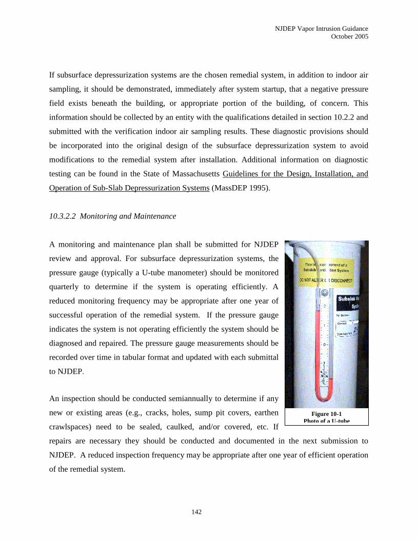
NJDEP Vapor Intrusion Guidance
October 2005
142
If subsurface depressurization systems are the chosen remedial system, in addition to indoor air
sampling, it should be demonstrated, immediately after system startup, that a negative pressure
field exists beneath the building, or appropriate portion of the building, of concern. This
information should be collected by an entity with the qualifications detailed in section 10.2.2 and
submitted with the verification indoor air sampling results. These diagnostic provisions should
be incorporated into the original design of the subsurface depressurization system to avoid
modifications to the remedial system after installation. Additional information on diagnostic
testing can be found in the State of Massachusetts Guidelines for the Design, Installation, and
Operation of Sub-Slab Depressurization Systems (MassDEP 1995).
10.3.2.2 Monitoring and Maintenance
A monitoring and maintenance plan shall be submitted for NJDEP
review and approval. For subsurface depressurization systems, the
pressure gauge (typically a U-tube manometer) should be monitored
quarterly to determine if the system is operating efficiently. A
reduced monitoring frequency may be appropriate after one year of
successful operation of the remedial system. If the pressure gauge
indicates the system is not operating efficiently the system should be
diagnosed and repaired. The pressure gauge measurements should be
recorded over time in tabular format and updated with each submittal
to NJDEP.
An inspection should be conducted semiannually to determine if any
new or existing areas (e.g., cracks, holes, sump pit covers, earthen
crawlspaces) need to be sealed, caulked, and/or covered, etc. If
repairs are necessary they should be conducted and documented in the next submission to
NJDEP. A reduced inspection frequency may be appropriate after one year of efficient operation
of the remedial system.
Figure 10-1
Photo of a U-tube
manometer

NJDEP Vapor Intrusion Guidance
October 2005
143
10.3.2.3 Remedial Action Progress Report Submission
Remedial Action Progress Reports shall be submitted in accordance with The Technical
Requirements for Site Remediation (N.J.A.C. 7:26E).
10.3.2.4 System Termination Sampling
Once the investigator concludes that the VI source (ground water, soil gas, etc.) has been
properly remediated to the point where the VI pathway is not complete, a proposal may be
submitted to NJDEP to cease operation of the VI remedial system. Upon approval from NJDEP,
system termination sampling of indoor air and sub-slab soil gas should be collected. The system
termination sampling should occur during the winter and early spring (November through
March). Sampling should be conducted as outlined in Section 6.4 (Sub-Slab Soil Gas Sampling
Procedures) and Section 6.6 (Indoor Air Sampling Procedures). The system termination indoor
air and sub-slab analytical results should be submitted in a Remedial Action Progress Report for
NJDEP review. Note subsequent sampling rounds may be required on a case by case basis to
verify the appropriateness of system termination. Analytical parameters for the system
termination samples should include the contaminants of concern analyzed after the initial startup
of the remedial system. However, additional analytical parameters may be required on a case by
case basis.
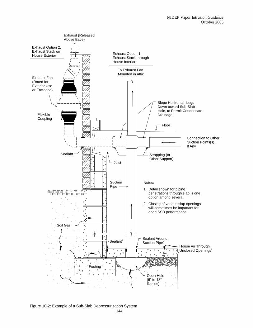
NJDEP Vapor Intrusion Guidance
October 2005
144
Open Hole(6” to 18”Radius)
House Air ThroughUnclosed Openings
2
SuctionPipe
Joist
Exhaust (ReleasedAbove Eave)
Exhaust Option 2:Exhaust Stack onHouse Exterior
Exhaust Fan(Rated forExterior Useor Enclosed)
FlexibleCoupling
Sealant
Soil Gas
Footing
Sealant2
Sealant AroundSuction Pipe
1
Notes:
1. Detail shown for piping penetrations through slab is one option among several.
2. Closing of various slap openings will sometimes be important for good SSD performance.
Strapping (orOther Support)
Connection to OtherSuction Points(s),If Any
Exhaust Option 1:Exhaust Stack throughHouse Interior
To Exhaust FanMounted in Attic
Floor
Slope Horizontal LegsDown toward Sub-SlabHole, to Permit CondensateDrainage
Figure 10-2: Example of a Sub-Slab Depressurization System
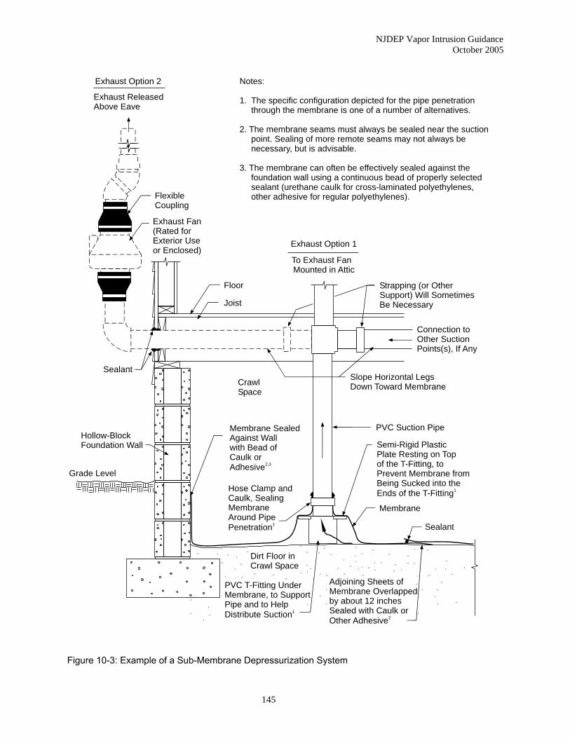
NJDEP Vapor Intrusion Guidance
October 2005
145
Notes:
1. The specific configuration depicted for the pipe penetration through the membrane is one of a number of alternatives.
2. The membrane seams must always be sealed near the suction point. Sealing of more remote seams may not always be necessary, but is advisable.
3. The membrane can often be effectively sealed against the foundation wall using a continuous bead of properly selected sealant (urethane caulk for cross-laminated polyethylenes, other adhesive for regular polyethylenes).
Exhaust Option 2
Exhaust ReleasedAbove Eave
Exhaust Fan(Rated forExterior Useor Enclosed)
FlexibleCoupling
CrawlSpace
Hollow-BlockFoundation Wall
Grade Level
Floor
Joist
Sealant
Strapping (or Other Support) Will SometimesBe Necessary
To Exhaust Fan Mounted in Attic
Exhaust Option 1
Connection toOther Suction Points(s), If Any
Slope Horizontal LegsDown Toward Membrane
PVC Suction Pipe
Semi-Rigid PlasticPlate Resting on Topof the T-Fitting, toPrevent Membrane fromBeing Sucked into theEnds of the T-Fitting
1
Adjoining Sheets ofMembrane Overlappedby about 12 inchesSealed with Caulk orOther Adhesive
2
PVC T-Fitting UnderMembrane, to SupportPipe and to HelpDistribute Suction
1
Dirt Floor in Crawl Space
Hose Clamp andCaulk, SealingMembraneAround PipePenetration
1
Membrane SealedAgainst Wallwith Bead ofCaulk orAdhesive
2,3
Membrane
Sealant
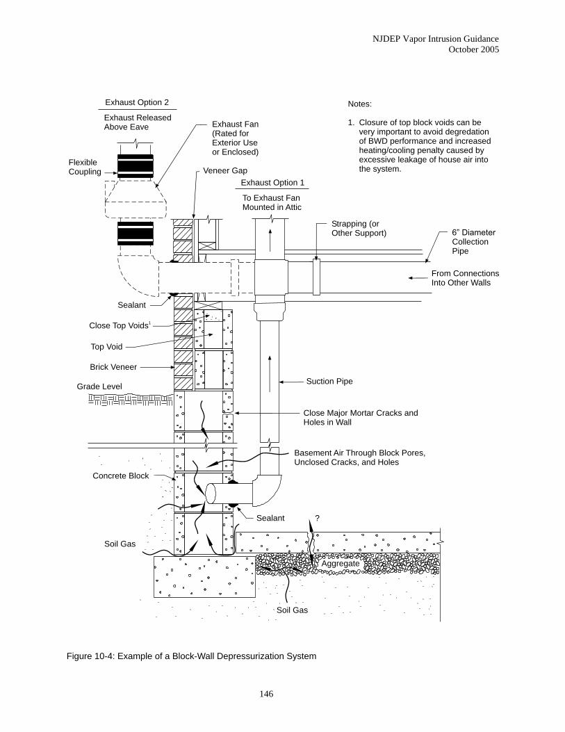
NJDEP Vapor Intrusion Guidance
October 2005
146
Aggregate
Exhaust Option 2
Exhaust Option 1
Close Top Voids1
6” DiameterCollection Pipe
Suction Pipe
Exhaust ReleasedAbove Eave
To Exhaust FanMounted in Attic
Exhaust Fan(Rated forExterior Useor Enclosed)
FlexibleCoupling
Sealant
Notes:
1. Closure of top block voids can be very important to avoid degredation of BWD performance and increased heating/cooling penalty caused by excessive leakage of house air into the system.
Strapping (orOther Support)
From ConnectionsInto Other Walls
Figure 10-4: Example of a Block-Wall Depressurization System
Veneer Gap
Top Void
Brick Veneer
Grade Level
Concrete Block
Close Major Mortar Cracks andHoles in Wall
Basement Air Through Block Pores,Unclosed Cracks, and Holes
Sealant
Soil Gas
?
Soil Gas
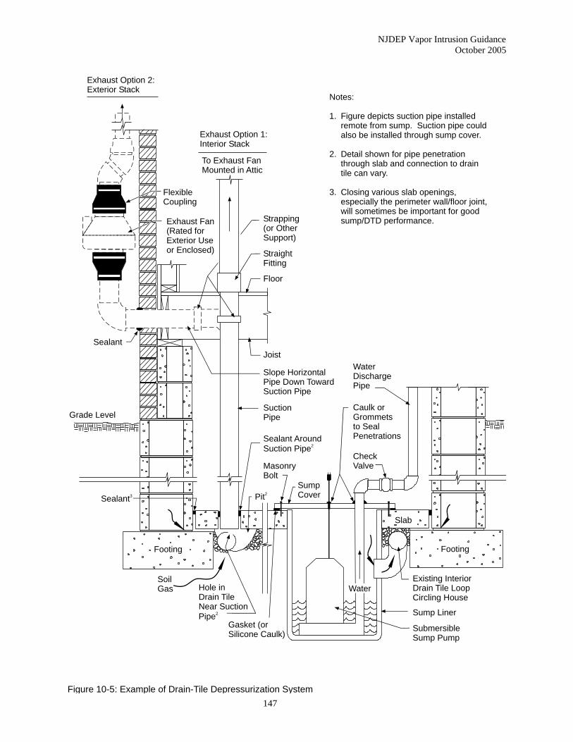
NJDEP Vapor Intrusion Guidance
October 2005
147
Exhaust Option 2:Exterior Stack
Exhaust Option 1:Interior Stack
Strapping(or OtherSupport)
Joist
Exhaust Fan(Rated forExterior Useor Enclosed)
FlexibleCoupling
To Exhaust FanMounted in Attic
Sealant
Notes:
1. Figure depicts suction pipe installed remote from sump. Suction pipe could also be installed through sump cover.
2. Detail shown for pipe penetration through slab and connection to drain tile can vary.
3. Closing various slab openings, especially the perimeter wall/floor joint, will sometimes be important for good sump/DTD performance.
Existing InteriorDrain Tile LoopCircling House
Figure 10-5: Example of Drain-Tile Depressurization System
Grade Level
Sealant3
SubmersibleSump Pump
SoilGas
Gasket (orSilicone Caulk)
StraightFitting
Floor
Slope HorizontalPipe Down TowardSuction Pipe
SuctionPipe
Sealant AroundSuction Pipe
2
MasonryBolt
Pit2
SumpCover
WaterDischargePipe
Caulk orGrommetsto SealPenetrations
CheckValve
Slab
Footing
Sump Liner
WaterHole inDrain TileNear SuctionPipe
2
Footing
NJDEP Vapor Intrusion Guidance
October 2005
148
11.0 COMMUNITY OUTREACH FOR VAPOR INTRUSION SITES
11.1 About the Office of Community Relations
NJDEP’s Office of Community Relations (OCR) is responsible for facilitating open dialogue
with communities about site investigations and cleanups in their neighborhoods. OCR has
developed the following recommendations for NJDEP staff, responsible parties and
environmental investigators to consider when conducting community outreach for VI sites.
While each site will be different and therefore have unique community outreach needs, this
guidance addresses general issues and concerns encountered at most VI sites.
NJDEP encourages responsible parties and their consultants to contact OCR before initiating a
community outreach program so the appropriate roles of all parties can be determined. For
contact information, please refer to the OCR web page at www.nj.gov/dep/srp/community.
11.2 Why Do Community Outreach?
Early, two way communication with residents, business owners and local officials affected by a
contaminated property can be critical to a successful investigation and cleanup. When citizens
are well informed about the issues surrounding a site, their questions and concerns can be more
easily addressed. This builds trust and credibility and allows the remedial process to proceed
most efficiently.
An effective outreach strategy that anticipates the needs and concerns of the community will be
particularly important to a VI investigation. In most cases, the parties conducting the
investigation will need to arrange sampling testing appointments with residents/property owners,
collect indoor air and soil gas samples, and report the findings. At some properties sub-surface
depressurization systems may be required. Public meetings may be necessary to ensure the
general public is properly informed about the investigation and remedial actions. Those involved
in a VI investigation will want to develop their community outreach strategy before the actual
work begins to ensure the most successful outcome.
NJDEP Vapor Intrusion Guidance
October 2005
149
11.3 Communicating with the Public about Vapor Intrusion
When initiating a VI investigation, there are at least two key groups that need to be notified: the
local officials and the general public. The media may emerge as a third group if the site becomes
high profile. Below are some tips on how and when to communicate with these parties for
maximum effectiveness.
11.3.1 Local Officials
Before beginning a VI investigation, notify the municipal officials (e.g., municipal clerk,
township administrator, mayor) and the local health officer that indoor air and/or soil gas
sampling is going to be conducted in their area and why it is being done. As the elected or
appointed leaders of the community, the media or residents will likely contact them for
information. (If site activities include going door to door to collect information from residents or
any other type of canvassing, the local police department should also be notified.)
Establish a working relationship with the local officials early in the process so they can be
involved as needed later on. Provide local officials with copies of the Evaluating Indoor Air near
VOC Contaminated Sites and Subsurface Depressurization Systems fact sheets and inform them
of the availability of this guidance document on NJDEP’s web site,
http://www.nj.gov/dep/srp/guidance/vaporintrusion/. Let them know that you may be copying
them on correspondence to residents regarding the VI investigation.
11.3.2 General Public
When communicating with the general public about the investigation, remember that the nature
of VI, how it is evaluated, sources of background contamination, possible health effects and
potential remedies will likely be unfamiliar concepts. Expect to expend significant effort
educating residents/property owners and local officials about these topics before conducting an
indoor air investigation. If there is a large population of sensitive individuals (e.g., small children
in school or daycare) in the area being investigated, or if there has already been significant media
NJDEP Vapor Intrusion Guidance
October 2005
150
attention focused on the site, it may be helpful to hold a public meeting before the VI
investigation work begins. Section 11.8 has information on holding public meetings.
When discussing VI, be sure to define technical jargon and explain complex concepts in a
manner that can be easily understood. Provide supplemental literature, such as fact sheets, or
identify a web site they can go to for more information about the site. Ask for feedback to ensure
the public understands the information. In addition, find out how they would like to be notified
about developments in the future.
Since people living in indoor air contamination areas are directly affected by the site, the
investigator should be prepared to engage in frequent contact with the residents/property owners
(phone calls, letters, meetings, etc.).
Finally, some residents may feel that owning a home affected by VI carries a stigma.
Acknowledge these concerns and explain the level of confidentiality they can expect regarding
their indoor air results and any remedial actions that may be taken at their homes.
11.3.3 Media
A site does not have to be particularly large or complex to garner attention from local
newspapers, television stations, or other media outlets. In cases where the media have focused
on the VI investigation, it is always advisable to make background material available (as long as
the confidentiality of individual test results is maintained). If a site is or may become
controversial, it may be a good idea to take the initiative to release information about the VI
investigation rather than wait for a news story to break.
11.4 Arranging Sample Appointments
The Department recommends a two step approach when initially contacting residents/property
owners to obtain permission to conduct an VI investigation at their buildings. First, send an
introductory letter to the residents/property owners to inform them of the proposed VI
NJDEP Vapor Intrusion Guidance
October 2005
151
investigation at their buildings. Follow up with phone calls to the residents to arrange sampling
appointments.
11.4.1 Letters
Send the introductory letters several weeks ahead of the sampling event. For rental properties,
send the letters to both the property owners and tenants. Write the letters in non-technical terms
and include the following information:
• an explanation for the reason for the sampling
• the name of the contaminant(s) of concern
• the anticipated sampling date (or approximate timeframe)
• who will be doing the sampling
• what the sampling will involve
• the phone numbers of NJDEP case manager, Community Relations coordinator
and/or other contacts.
Also include the following attachments, which are available from this guidance document and on
NJDEP web page [http://www.nj.gov/dep/srp/guidance/vaporintrusion/]:
• Evaluating Indoor Air near VOC Contaminated Sites (Appendix D)
• Instructions for Occupants – Indoor Air Sampling Events (Appendix C [English] and
C1 [Spanish])
• Indoor Air Building Survey and Sampling Form (Appendix B)
It may also be helpful to enclose specific information about the contaminant(s) of concern, such
as ToxFAQTM fact sheet(s) about the chemical(s) from the Agency for Toxic Substance and
Disease Registry (ASTDR) web page [http://www.atsdr.cdc.gov/atsdrhome.html].
Finally, if plans include collecting sub-slab or near slab soil gas samples, attach an access
agreement for the recipient to sign and return. For rental properties, the access agreement need
only be attached to the letter to the property owner.
NJDEP Vapor Intrusion Guidance
October 2005
152
Note: It is important to keep municipal officials apprised of your activities at this stage. Provide
them with a sample introductory letter and a list of the names and addresses of the
residents/property owners that have been contacted to request an indoor air investigation.
11.4.2 Phone Calls
Call the occupants of the buildings to arrange the sampling appointments at least two weeks prior
to the scheduled sampling event. Ask local contacts to help get in touch with occupants that are
not available or responsive. When calling to arrange the appointments, be prepared to discuss
the following:
• the contaminant(s) of concern, including the NJDEP Indoor Air Screening Level(s)
• general health issues - direct specific health questions to the local health department
• how the sample(s) will be collected and analyzed
• when the analytical results will be available and possible remedial actions
• how to prepare for the sampling and what to avoid when sampling is being conducted,
as outlined in Instructions for Occupants – Indoor Air Sampling Events
In addition, review the Indoor Air Building Survey and Sampling Form with the occupant.
Inform the occupant that someone knowledgeable about the property should be available on the
day of sampling to help the sampling team to fill out the form. If that is not possible, try to fill
out the form over the phone with the occupant.
When arranging follow up indoor testing appointments (such as confirmation sampling or
sampling to check the effectiveness of a remedial action), it is only necessary to contact the
residents/property owners by telephone. As a courtesy, try to give residents/property owners at
least two weeks notice of the planned sampling. When scheduling follow up appointments,
always review the recommendations outlined in Instructions for Occupants – Indoor Air
Sampling Events with the residents/property owners to remind them about how to prepare for the
sampling and what to avoid while the sampling is being conducted.
NJDEP Vapor Intrusion Guidance
October 2005
153
11.5 Collecting Samples
When entering homes and other private buildings to conduct air sampling, NJDEP recommends
sending a team of two people. Each sampling team member should bring identification for
verification by the residents should it be requested. If a Community Relations coordinator is
assigned to the site, that person should be present on the first day to meet the occupants of the
buildings, help fill out the building survey and answer questions. If a Community Relations
coordinator is not assigned to the site, the sampling team should be prepared to provide the
occupants with the name and telephone number of a contact person to whom they can direct
questions.
Note: In light of recent concerns about homeland security, it is highly recommended that
precautions be taken whenever the VI investigation includes outside air sampling. The sampling
equipment (stainless steel canisters) and related devices are not familiar to most people and may
be misinterpreted as a safety concern. Therefore, the local police and fire departments should be
notified of the sampling event in addition to the municipal officials. It may be useful to
demonstrate the operation of the sampling equipment to these officials. A label should be affixed
to the sampling device explaining the nature of the equipment and contact information in case
there are further questions.
11.6 Reporting Sample Results
Although investigators may elect to forward results (or be bound to do so by an access
agreement), NJDEP is responsible for officially notifying property owners/occupants about their
sampling results when there is an oversight document. The written reports from NJDEP will
consist of a cover letter explaining the findings and a table summarizing the analytical results.
In addition to written results, the NJDEP may first call the residents/property owners to report
results under the following scenarios:
NJDEP Vapor Intrusion Guidance
October 2005
154
• The analytical results indicate that VI is causing one or more contaminants of concern to
exceed the NJDEP RAL. This will give the occupant/property owner the opportunity to
discuss the results as soon as they become aware of them.
• Very high levels of background contaminants are found in the indoor air. This may allow
the resident/property owner to take immediate measures to reduce their exposure to these
contaminants by addressing the source. Occupants/property owners should be referred to
their local health department if they have specific health questions about non-site related
contaminants.
• A significant period of time has elapsed (more than eight weeks) since the testing was
conducted. Residents who are anxious about their results will appreciate receiving them
verbally if it speeds the process.
11.6.1 Verbal Reports
When reporting indoor air results verbally, NJDEP will provide the results directly to the
property owner and/or resident, since leaving the information on an answering machine or with
another person can lead to a misunderstanding of the findings and/or breach confidentiality.
Once residents/property owners know their indoor air testing results, NJDEP will explain the
next action, if any, and when they can expect to receive written copies of their results. NJDEP
will also provide the name and phone number of a contact person in case the resident/property
owner has follow up questions.
11.6.2 Written Reports
The written reports from NJDEP will consist of a cover letter explaining the findings and a table
summarizing the analytical results. The purpose of the cover letter is to put the results in a
context that the resident/property owner can easily understand. In the case of rental properties,
the findings should be reported in writing to both the tenant and the property owner. The local
health officer will be copied on all letters to residents.
NJDEP Vapor Intrusion Guidance
October 2005
155
Note: If the sampling reveals that vapor intrusion may be occurring at the property, the letter
should include language informing the owner of the Property Condition Disclosure requirements
as per N.J.A.C. 13:45A-29.1.
The cover letter should be written in non-technical terms and include the information listed
below.
• The date the sampling was conducted
• Who conducted the sampling (e.g., name of government agency or private contractor)
• The site for which the sampling was conducted (if applicable)
• The sample location/address, including the block and lot
• An explanation of the findings with the contaminant(s) of concern highlighted
• The next action, if any, for the property (e.g., another round of sampling or a remedial
action)
• A brief discussion of the indoor air contaminants detected that are not related to the site.
(Refer the resident/property owner to their local health department if they have
questions about non-site related indoor air contaminants.)
• Name and telephone number of a NJDEP contact person and a representative from the
local health department.
Also attach copies of the Common Household Sources of Background Indoor Air Contamination
(Appendix H) and the Subsurface Depressurization Systems fact sheet (Appendix E), if
applicable.
The analytical results summary table should be in a format that is easy to understand. Enclosing
the summary tables from the laboratory analytical data package is not recommended, as these are
often very technical. The table should include all of the compounds that were analyzed for, the
IASL for each compound and the concentration of each compound that was detected during the
indoor air sampling (both reported in g/m3).
NJDEP Vapor Intrusion Guidance
October 2005
156
11.7 Community Outreach during Remedial Actions
Most of the community outreach conducted during the Remedial Action phase will entail acting
as a point of contact between the occupant/property owner and the contractor or state regulators.
This can include scheduling the installation of the remedial system, relaying the property
owner’s concerns to the appropriate individuals, and ensuring that every effort is made to resolve
issues or concerns related to the remedial action.
As stated earlier, some people may feel that owning a home with vapor intrusion carries a
stigma. Before beginning the remedial work, make sure the occupant/property owner is
comfortable with the final design. In all cases, the finished remedial system should be as
inconspicuous as possible.
Finally, as part of the community outreach for a VI investigation/remedial action, measures
should be taken to ensure that the property owner understands that it is his responsibility to
inform current and future occupants of the building about the vapor intrusion issues at the
property.
11.8 Meeting with the Public
When VI sites generate significant community interest, public meetings can be useful forums for
disseminating information and answering questions (see options below). These are held in
coordination with NJDEP at a municipal building, school or other public building in the area
near the site.
Consult with local officials to determine the best day and time and give the public several weeks
notice of the meeting date. Weekday evenings are usually the most convenient times for such
meetings. After a date and time has been selected, ask the local council to announce the
upcoming meeting at their meetings. Mail notices of the meeting to residences abutting and near
the site. It is also advisable to publish a notice of the meeting in the local newspaper.
NJDEP Vapor Intrusion Guidance
October 2005
157
There are three possible formats for the public meeting. The first is in conjunction with a local
council meeting. Engage local assistance on how to notify the public of the presentation, how
long it should be, how questions will be asked, and other issues pertaining to the presentation.
The second type of meeting is a formal presentation with a question and answer period. The
investigating party makes all of the arrangements for this type of meeting after getting input from
local officials. The investigating party establishes the format of the meeting and runs the
meeting.
The third more informal format is a public availability session or “open house.” As with the
more formal presentation, the investigating party arranges the meeting after conferring with the
local officials. This type of meeting is largely unstructured, allowing the public to speak one to
one with the professionals involved in the investigation in a relatively private setting. A short
presentation may be included if desired.
The panelists for the public meeting should include geologists, public health officials,
toxicologists, case team members and others knowledgeable about the site and its potential
health effects. When presenting data about the site to the public, remember confidentiality may
be an issue for some residents/property owners. For this reason, maps or other documents
identifying specific homes with indoor air contamination may not be suitable presentation
materials.
During the meeting, note concerns and issues raised by the public and local officials that cannot
be answered or addressed immediately. Provide responses to these concerns and issues as
quickly as possible once the public meeting or public availability session is over. In the weeks
and months following the meeting, continue to periodically update the residents and local
officials on the VI investigation and any remedial actions through fact sheets, letters and
telephone calls.
NJDEP Vapor Intrusion Guidance
October 2005
158
11.9 Additional Information
Both NJDEP and USEPA offer guidance on risk communication. The NJDEP report
Establishing Dialogue AND Planning Success: A Guide to Effective Communication Planning is
available at www.state.nj.us/dep/dsr/pub.htm. For USEPA’s guidance, see
[www.epa.gov/superfund/tools/pdfs/37riskcom.pdf]. NJDEP strongly recommends that parties
investigating VI sites familiarize themselves with the concepts in these documents, particularly
USEPA’s The Seven Cardinal Rules of Risk Communication, when preparing their community
outreach activities for VI sites.

NJDEP Vapor Intrusion Guidance
October 2005
159
REFERENCES
Baek, S.O., Y.S. Kim, and R. Perry. 1997. “Indoor Air Quality in Homes, Offices and
Restaurants in Korean Urban Areas-Indoor/Outdoor Relationships”, Atmospheric
Environment, 31(4): 529-544.
Berry-Spark, K., T. McAlary, N. Bice, M. DeFlaun, and P. Zeeb. 2004. “Risk Management
Approaches at Vapor Intrusion Sites – Chlorinated Solvents Case Studies.” Platform
presentation at the Fourth International Conference on Remediation of Chlorinated and
Recalcitrant Compounds, Monterey, CA May 24-27, 2004.
Bonanno, L.J. 2000. “Household Characteristics, Activities and Contamination: Exposure
Assessment for Children in the NHEXAS Population,” Ph.D. dissertation, Rutgers, the
State University of New Jersey and University of Medicine and Dentistry of New Jersey.
California Environmental Protection Agency (Cal EPA). 1997. Health Effects of Exposure to
Environmental Tobacco Smoke. Office of Environmental Health Hazard Assessment.
Chemical Rubber Company. 1972. CRC Handbook of Chemistry and Physics, 53rd ed., Weast,
R.C., editor, CRC Press, Cleveland, OH.
Clayton, C.A., E.D. Pellizzari, R.W. Whitmore, R.L. Perritt, and J.J. Quackenboss 1999.
“National Human Exposure Assessment Survey (NHEXAS): Distributions and
Associations of Lead, Arsenic and Volatile Organic Chemicals in EPA Region 5”, J.
Exposure Anal. and Environ. Epidemiology, 9: 381-392.
DeVaull, G.E., R.A. Ettinger, J.P. Salanitro, and J.B. Gustafson. 1997. “Benzene, Toluene,
Ethylbenzene and Xylenes [BTEX] Degradation in Vadose Zone Soils during Vapor
Transport: First-Order Rate Constants.” In Proceedings of the Petroleum Hydrocarbons
and Organic Chemicals in Groundwater Conference: Prevention, Detection and
Remediation, November 12-14, 1997, Houston, TX. Ground Water Publishing Company,
Westerville, Ohio, 365-379.
DiGiulio, D., R. Cody, R. Mosley, R. Willey, A. Lee, C. Paul, S. Clifford, K. Christensen, and P.
Kahn. 2005. Assessment of Vapor Intrusion Using Sub-Slab Air Samples 1. Guidelines
for Installation and Sampling of Sub-Slab Vapor Probes. Draft.
Edwards, R.D., J. Jurvelin, K. Saarela, and M. Jantunen. 2001. “VOC Concentrations Measured
in Personal Samples and Residential Indoor, Outdoor and Workplace Microenvironments
in EXPOLIS-Helsinki, Finland,” Atmospheric Environment, 35: 4531-4543.
Fitzpatrick, N. and J. Fitzgerald. 2002. “An Evaluation of Vapor Intrusion Into Buildings through
a Study of Field Data,” Soil and Sediment Contamination, 11(4):603-623.
www.mass.gov/dep/bwsc/files/gw2proj.pdf

NJDEP Vapor Intrusion Guidance
October 2005
160
Girman, J. 2000. BASE (Building Assessment Survey and Evaluation): Indoor Air in Typical
Environments. Presented at the RCRA Corrective Action EI Forum, August 15, 2000,
Washington DC.
Gordon, S.M., P.J. Callahan, M.G. Nishioka, M.C. Brinkman, M.K. O’Rourke, M.D. Lebowitz,
and D.J. Moschandreas. 1999. “Residential Environmental Measurements in the National
Human Exposure Assessment Survey (NHEXAS) Pilot Study in Arizona: Preliminary
Results for Pesticides and VOCs,” J. Exposure Anal. and Environ. Epidemiology, 9: 456-
470.
Griesemer, J.. 2001. “Diving Plumes that Migrate to Depths Below the Water Table,” SRP
Newsletter, May 2001, 13 (1): Pgs.7-11,
(Available at www.state.nj.us/dep/srp/news/srn_index_a.htm#g)
Hartman, B.. 1998. “The Downward Migration of Vapors,” LUSTLine Bulletin 28, February
1998.
Hartman, B.. 2004. “Vapor Monitoring Wells/Implants Standard Operating Procedures,” H&P
Mobile Geochemistry, Solana Beach, California.
Hazardous Substances Data Bank. 2004. National Library of Medicine: Bethesda.
http//toxnet.nlm.nih.gov/servlets/simple-search.
Hers, I. 2004. Overview of Vapor Intrusion Attenuation Data. Presented at the Vapor Intrusion
Attenuation Workshop, 14th Annual West Coast Conference on Soils, Sediments and
Water, March 15-18, 2004, San Diego, California.
Hers, I. and T. Rees. 2005. NJDEP-Golder Subsurface Vapor Intrusion Research Project Year
One Soil Vapor Intrusion Research Study at Stafford Township and Egg Harbor Sites,
New Jersey. Golder Associates Inc.
Hers, I., R. Zapf-Gilje, P.C. Johnson and L. Li. 2003. “Evaluation of the Johnson and Ettinger
model for prediction of indoor air quality,” Ground Water Monitoring & Remediation 23:
119-133.
Hughes, B.M., R.W. Gillham, and C.A. Mendoza. 1996. “Vapor Transport of Trichloroethylene
in the Unsaturated Zone: Field and Numerical Modeling Investigations,” Water
Resources Research 32:9–22.
Hurlbert, R. T. 1994. Comprehending Behavioral Statistics. Brooks/Cole Publishers, Pacific
Grove, CA.
Jantunen, M.J., O. Hänninen, K. Katsouyanni, H. Knöppel, N. Kuenzli, E. Lebret, M. Maroni, K.
Saarela, R. Srám, and D. Zmirou. “Draft Final Report: Air Pollution Exposure in
European Cities: the "EXPOLIS" Study,” DRAFT.
NJDEP Vapor Intrusion Guidance
October 2005
161
Johnson, P.C. and R.A. Ettinger. 1991. “Heuristic Model for Predicting the Intrusion Rate of
Contaminant Vapors into Buildings,” Environmental Science and Technology 25: 1445-
1452.
Kostianen, R. 1995. “Volatile Organic Compounds in the Indoor Air of Normal and Sick
Houses,” Atmospheric Environment, 29(6): 693-702.
Lee, S.C., W.M. Li, and C.H. Ao. 2002. “Investigation of indoor air quality at residential homes
in Hong Kong - case study,” Atmospheric Environment, 36: 225-237.
Marrin, D.L. and G.M. Thompson. 1987. “Gaseous Behavior of TCE Overlying a Contaminated
Aquifer,” GROUNDWATER, 25 (1): 21-27.
Massachusetts Department of Environmental Protection (MassDEP). 1995. Guidelines for the
Design, Installation, and Operation of Sub-Slab Depressurization Systems. Northeast
Regional Office. BWSC/NERO/SSD/95-12.
Massachusetts Department of Environmental Protection (MassDEP). 2002. Draft Indoor Air
Sampling and Evaluation Guide. Office of Research and Standards.
McAlary, T. 2003. “Conceptual Models of Vapor Intrusion,” GeoSyntec Consultants, Inc.,
Presentation for USEPA Seminar on Indoor Air Vapor Intrusion, February 25-26, 2003,
Session 2.
McAlary, T.A., K. Berry-Spark, T.A. Krug, and J.M. Uruskyj. 2004. "The Fresh Water Lens and
its Effects on Groundwater to Indoor Air Attenuation Coefficients," an invited
presentation at the USEPA Vapor Intrusion Workshop held at the AEHS 14th Annual
West Coast Conference on Soils, Sediment and Water, San Diego, March 15-18, 2004.
McAlary, T.. 2004. Personal correspondence, GeoSyntec Consultants.
Mendoza, C. and T. McAlary. 1990. “Modeling of Ground-Water Contamination Caused by
Organic Solvent Vapors,” GROUND WATER, 28 (2):199-206.
New Jersey Department of Environmental Protection (NJDEP). 1999. Indoor Air Sampling
Guide for Volatile Organic Contaminants. NJDEP, Hazardous Site Science Element,
Trenton, NJ.
New Jersey Department of Environmental Protection (NJDEP). 2003a. Technical Requirements
for Site Remediation. New Jersey Administrative Code N.J.A.C. 7:26 E.
New Jersey Department of Environmental Protection (NJDEP). 2003b. Professional Laboratory
Services Contract for Laboratory Analysis of Air Samples Collected at Hazardous Waste
Sites, August 2003, Bid Number 03-X-35135.
NJDEP Vapor Intrusion Guidance
October 2005
162
New Jersey Department of Environmental Protection (NJDEP). 2003c. Contract User Guide:
Laboratory Analysis of Air Samples Collected at Hazardous Waste Sites. NJDEP,
Hazardous Site Science Element, Trenton, NJ.
New Jersey Department of Environmental Protection (NJDEP). 2005. Field Sampling Procedures
Manual (FSPM).
New York State Department of Health (NYSDOH). 2005. Guidance for Evaluating Soil Vapor
Intrusion in the State of New York. Public Comment Draft.
Ott, W. and J. Roberts. 1998. "Everyday Exposure to Toxic Pollutants," Scientific American
278(2): 86-91.
Pennsylvania Department of Environmental Protection (PA DEP). 2004. Land Recycling
Program Technical Guidance Manual - Section IV.A.4. Vapor Intrusion into Buildings
from Groundwater and Soil under the Act 2 Statewide Health Standard, Doc. No 253-
0300-100.
Puls, R.W., and C.J. Paul. 1998. “Discrete-Level Ground-Water Monitoring System for
Containment and Remedial Performance Assessment Objectives,” J. Env. Engineering,
124(6): 549-553.
Reilly, T.E., and J. Gibs. 1993. “Effects of Physical and Chemical Heterogeneity on Water-
Quality Samples Obtained from Wells,” GROUND WATER, 31(5).
Ririe, G.T., R.E. Sweeney, and S.J. Daugherty. 2002. “A Comparison of Hydrocarbon Vapor
Attenuation in the Field with Predictions from Vapor Diffusion Models,” Soil and
Sediment Contamination 11: 529-554.
Rivett, M.O. 1995. “Soil-Gas Signatures from Volatile Chlorinated Solvents: Borden Field
Experiments,” GROUND WATER, 33(1).
Roggemans, S., C.L. Bruce, P.C. Johnson, and R. L. Johnson. 2001. Vadose Zone Natural
Attenuation of Hydrocarbon Vapors: An Empirical Assessment of Soil Gas Profile Data.
API Technical Bulletin No. 15.
Sanders, P.F. and I. Hers. 2005. “Vapor Intrusion in Homes Over Gasoline-Contaminated
Groundwater in Stafford, NJ,” Ground Water Monitoring and Remediation, (in press).
Schwille, F.. 1988. Dense Chlorinated Solvents in Porous and Fractured Media, Model
Experiments, Lewis Publishers, Inc., Chelsea, MI
Sexton, K., J.L. Adgate, G. Ramachandran, G.C. Pratt, S.J. Mongin, T.H. Stock, and M.T.
Morandi. (2004). “Comparison of Personal, Indoor, and Outdoor Exposures to Hazardous
Air Pollutants in Three Urban Communities,” Environ. Sci. Technol., 38 (2): 423-430.
NJDEP Vapor Intrusion Guidance
October 2005
163
Tedrow J.F. 1986. Soils of New Jersey. R.E. Krieger: Malabar, FL.
Thompson, G.M. and D.L. Marrin. 1987. “Soil Gas Contaminant Investigations: A Dynamic
Approach,” Ground Water Monitoring Review VII (3).
United States Department of Agriculture (USDA). 1999. Soil Survey Geographic (SSURGO)
Database for New Jersey. USDA Natural Resources Conservation Service, Fort Worth,
TX.
U.S. Environmental Protection Agency (USEPA). 1987. The Total Exposure Assessment
Methodology (TEAM) Study: Summary and Analysis, Volume 1, U.S. Environmental
Protection Agency, Washington, DC, EPA-600/6-87 002a (PB88-100060).
U.S. Environmental Protection Agency (USEPA). 1988. National Ambient Volatile Organic
Compounds (VOCs) Database Update. Atmospheric Sciences Research Laboratory.
U.S. Environmental Protection Agency (USEPA). 1993. Radon Reduction Techniques for
Existing Detached Houses – Technical Guidance (Third Edition) for Active Soil
Depressurization Systems. EPA 625/R-93-001, October 1993.
U.S. Environmental Protection Agency (USEPA). 1994. Radon Mitigation Standards. EPA 402-
R-93-078, October 1993 (Revised April 1994).
U.S. Environmental Protection Agency (USEPA). 1996a. Soil Screening Guidance: Technical
Background Document. USEPA, Office of Emergency Response, Washington DC.
USEPA/540/R-95/128, PB96-963502.
U.S. Environmental Protection Agency (USEPA). 1996b. Superfund Chemical Data Matrix.
Office of Emergency and Remedial Response, Washington, D.C. EPA/540/R-96/028.
U.S. Environmental Protection Agency (USEPA). 1997 Update. Health Effects Assessment
Summary Tables. Office of Solid Waste and Emergency Response, Washington, DC.
USEPA 540-R-97-036, page 15.
U.S. Environmental Protection Agency (USEPA). 1999. Compendium of Methods for Toxic Air
Pollutants, Second Edition, Method TO-15. Center for Environmental Research
Information, Office of Research and Development. Cincinnati, OH.
U.S. Environmental Protection Agency (USEPA). 2001a. Supplemental Guidance for
Developing Soil Screening Levels for Superfund Sites, Draft Final, Office of Solid Waste
and Emergency Response, Washington, DC. OSWER 9355-4-24.
U.S. Environmental Protection Agency (USEPA). 2001b. Users Guide for WATER9 Software.
USEPA Office of Air Quality Planning and Standards, Research Triangle Park, North
Carolina.

NJDEP Vapor Intrusion Guidance
October 2005
164
U.S. Environmental Protection Agency (USEPA). 2001c. Healthy Buildings, Healthy People: A
Vision for the 21st Century. Office of Air and Radiation.
U.S. Environmental Protection Agency (USEPA). 2001d. Building Radon Out: A Step-by-Step
Guide on how to build Radon-Resistant Homes. Office of Air and Radiation. EPA/402-
K-01-002.
U.S. Environmental Protection Agency (USEPA).2001e.“Modeling Subsurface Petroleum
Hydrocarbon Transport, Plume Diving, OnSite on-line calculators,” US EPA Web Site.
http://www.epa.gov/athens/learn2model/part-two/onsite/i2k_onsite.htm
U.S. Environmental Protection Agency (USEPA). 2002a. "Role of Background in the CERCLA
Cleanup Program." Office of Solid Waste and Emergency Response.
U.S. Environmental Protection Agency (USEPA). 2002b. Draft Guidance for Evaluating the
Vapor Intrusion to Indoor Air Pathway from Groundwater and Soils (Draft Subsurface
Vapor Intrusion Guidance). Office of Solid Waste and Emergency Response,
Washington, DC. USEPA530-F-02-052
U.S. Environmental Protection Agency (USEPA). 2003. Consumer's Guide to Radon Reduction.
Office of Air and Radiation, Office of Radiation and Indoor Air (6609J).402-K-03-002,
Revised February 2003.
U.S. Environmental Protection Agency (USEPA). 2004a. Vapor Intrusion Attenuation
Workshop: A Study of Observed Vapor Intrusion Attenuation. Presented at the USEPA
Vapor Intrusion Attenuation Workshop at the 14th Annual West Coast Conference on
Soils, Sediments and Water, March 15-18, 2004, San Diego, California.
U.S. Environmental Protection Agency (USEPA). 2004b. Modeling Vapor Attenuation
Workshop: A Study of Vapor Intrusion Modeling in the Context of EPA’s Guidance.
Presented at the 20th Annual International Conference on Soils, Sediments and Water,
October 18-21, 2004, Amherst Massachusetts.
U.S. Environmental Protection Agency (USEPA). 2004c. “Users Guide and Background
Technical Document for USEPA Region IX Preliminary Remediation Goals Table,” San
Francisco, CA http://www.epa.gov/region09/waste/sfund/prg/files/04usersguide.pdf
U.S. Environmental Protection Agency (USEPA). 2004d. “User’s Guide for Evaluating
Subsurface Vapor Intrusion into Buildings,” Office of Emergency and Remedial
Response, Washington, DC http://www.epa.gov/oswer/riskassessment/airmodel/
johnson_ettinger.htm.
U.S. Environmental Protection Agency (USEPA). 2005. “Human Health Risk Assessment, Risk-
Based Concentration Table, April 2005 update,” USEPA Region III, Philadelphia, PA.
http://www.epa.gov/reg3hwmd/risk/human/index.htm.
U.S. Environmental Protection Agency (USEPA). “Integrated Risk Information System (IRIS),”
current. Cincinnati, OH. http://www.epa.gov/iris.htm.
NJDEP Vapor Intrusion Guidance
October 2005
165
United States Geological Survey (USGS). 2003. Personal communication.
Vroblesky, D.A. (editor) 2001. User’s Guide for Polyethylene-Based Passive Diffusion Bag
Samples to Obtain Volatile Organic Compound Concentrations in Wells, Part 2: Field
Tests, Water-Resources Investigations Report 01-4061, U.S. Department of the Interior
and U.S. Geological Survey, http://ds.itrcweb.org/DSP-1Part2.pdf
Wallace, L.A., E.D. Pellizzari, T.D. Hartwell, C.M. Sparacino, L.S. Sheldon, and H. Zelon.
1985. “Personal Exposures, Indoor-Outdoor Relationships, and Breath Levels of Toxic
Air Pollutants Measured for 355 persons in New Jersey,” Atmospheric Environment,
19(10): 1651-1661.
Wallace, L.A. 1987. Project Summary: The Total Exposure Assessment Methodology (TEAM)
Study, U.S. Environmental Protection Agency, Washington, DC, EPA/600/S6-87/002.
Weaver, J.W., J.E. Hass, and C.B. Sosik. 1999. “Characteristics of Gasoline Releases in the
Water Table Aquifer of Long Island,” presented at the National Ground Water
Association/American Petroleum Institute conference, November 1999 Petroleum
Hydrocarbons Conference and Exposition, Houston, Texas
Weaver, J.W. and J.T. Wilson. 2003. “Diving Plumes and Vertical Migration at Petroleum
Hydrocarbon Release Sites,” LL #36, U.S. Environmental Protection Agency, Office of
Research and Development,
http://www.epa.gov/nerl/mtbe/plume_diving.pdf
Weisel, C.P., M. Morandi, T. Stock, B. Turpin, J. Zhang, K. Mohan, S. Alimokhtari, and J.
Kwon. 2001. “Influence of Ambient Air Sources on VOC exposure in NJ in the RIOPA
(Relationship among Indoor, Outdoor & Personal Air) Study,” presented at Eleventh
Annual Meeting of the Society of Exposure Analysis, Charleston, SC, Nov. 4-8, 2001.
Wisconsin Department of Natural Resources (WDNR). 2000. Guidance for Documenting the
Investigation of Utility Corridors. PUBL-RR-649.
Won, D., Corsi, R.L., and Rynes, M. 2000. "New Carpet as an Adsorptive Reservoir for Volatile
Organic Compounds," Environmental Science & Technology 34 (19): 4193-4198.
Zhang, J., L. Zhang, R. Harrington, C. Weisel, L. Korn, M. Morandi, T. Stock, S. Colome, B.
Turpin, and D. Spektor. 2001. “Indoor, Outdoor, In-Vehicle concentrations of airborne
carbonyl compounds and their relation to personal exposure: Results from the RIOPA
study,” presented at Eleventh Annual Meeting of the Society of Exposure Analysis,
Charleston, SC, Nov. 4-8, 2001.
Zhu, J., R. Newhook, L. Marro, and C.C. Chan. (2005). “Selected Volatile Organic Compounds
in Residential Air in the City of Ottawa, Canada.” Environ. Sci. Technol., 39 (11):3964-
3971.

TABLES
APPENDIX A
Decision Flow Chart (Refer to Chapter 3 for additional guidance)
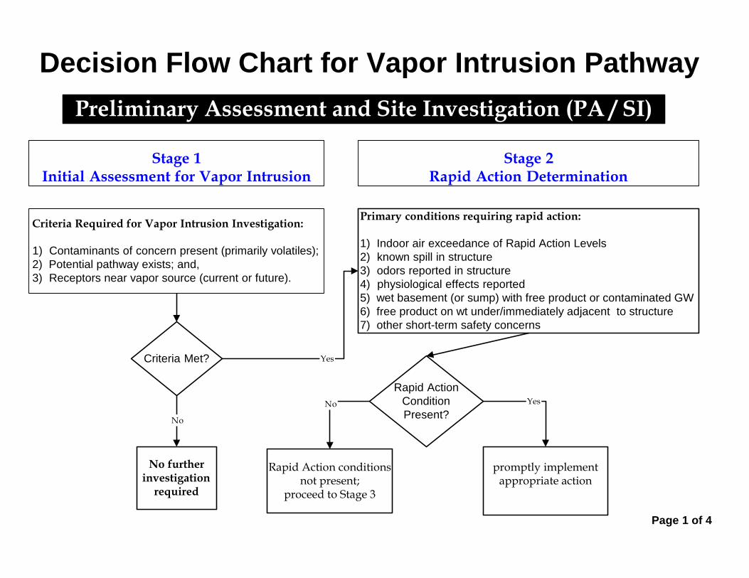
Primary conditions requiring rapid action:
1) Indoor air exceedance of Rapid Action Levels
2) known spill in structure
3) odors reported in structure
4) physiological effects reported
5) wet basement (or sump) with free product or contaminated GW
6) free product on wt under/immediately adjacent to structure
7) other short-term safety concerns
Decision Flow Chart for Vapor Intrusion Pathway
Preliminary Assessment and Site Investigation (PA / SI)
Rapid Action conditionsnot present;
proceed to Stage 3
promptly implementappropriate action
Page 1 of 4
Stage 1Initial Assessment for Vapor Intrusion
Stage 2Rapid Action Determination
Criteria Required for Vapor Intrusion Investigation:
1) Contaminants of concern present (primarily volatiles);
2) Potential pathway exists; and,
3) Receptors near vapor source (current or future).
Criteria Met? Yes
No furtherinvestigation
required
No
Rapid Action
Condition
Present?
YesNo

In order of preference:
Stage 4A - Ground Water (GW) Investigation Delineate ground water contamination; then go to Stage 5Stage 4B - Soil Gas Investigation Assess near slab and/or sub-slab soil gas (for existing structures) or exterior soil gas (for future use); then go to Stage 5Stage 4C - Indoor Air Investigation Conduct sub-slab soil gas and indoor air sampling; then go to Stage 5.
Decision Flow Chart for Vapor Intrusion Pathway
Remedial Investigation (RI)
Page 2 of 4
Stage 3Compare Existing Data
to Generic Screening Levels
Stage 4Develop & Implement VI Investigation Workplan
Compare Existing Data to:
1) NJDEP Ground Water Screening Levels;
2) NJDEP Soil Gas Screening Levels; and/or,
3) NJDEP Indoor Air Screening Levels.
If no existing data, proceed to Stage 4.
results exceed NJDEP
Screening Levels?
Yes
No
If indoor air exceedance, collectconfirmation samples ;
If GW or soil gas exceedance,acquire needed data throughVI Investigation Workplan
Are datavalid and
representative?
No
No furtherinvestigation
required
Yes
Are datavalid and
representative?
Acquire neededdata through
VI InvestigationWorkplan
No
Yes
PA / SI
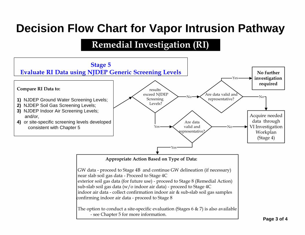
Decision Flow Chart for Vapor Intrusion Pathway
Remedial Investigation (RI)
Stage 5Evaluate RI Data using NJDEP Generic Screening Levels
Compare RI Data to:
1) NJDEP Ground Water Screening Levels;
2) NJDEP Soil Gas Screening Levels;
3) NJDEP Indoor Air Screening Levels;
and/or,
4) or site-specific screening levels developed
consistent with Chapter 5
results exceed NJDEP
Screening Levels?
NoAre data valid and
representative?
No furtherinvestigation
required
Yes
Are datavalid and
representative?
Acquire neededdata through
VI InvestigationWorkplan(Stage 4)
No
Yes
Yes
No
Appropriate Action Based on Type of Data:
GW data - proceed to Stage 4B and continue GW delineation (if necessary) near slab soil gas data - Proceed to Stage 4C exterior soil gas data (for future use) - proceed to Stage 8 (Remedial Action) sub-slab soil gas data (w/o indoor air data) - proceed to Stage 4C indoor air data - collect confirmation indoor air & sub-slab soil gas samplesconfirming indoor air data - proceed to Stage 8
The option to conduct a site-specific evaluation (Stages 6 & 7) is also available- see Chapter 5 for more information.
Page 3 of 4
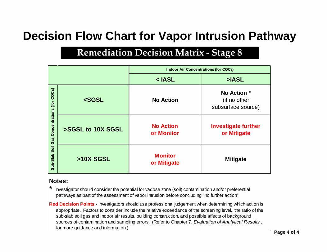
Decision Flow Chart for Vapor Intrusion Pathway
Remediation Decision Matrix - Stage 8
< IASL >IASL
<SGSL No Action
No Action *
(if no other
subsurface source)
>SGSL to 10X SGSLNo Action
or Monitor
Investigate further
or Mitigate
>10X SGSLMonitor
or MitigateMitigate
Notes:
pathways as part of the assessment of vapor intrusion before concluding "no further action"
for more guidance and information.)
Su
b-S
lab
So
il G
as C
on
cen
trati
on
s (
for
CO
Cs)
appropriate. Factors to consider include the relative exceedance of the screening level, the ratio of the
Red Decision Points - investigators should use professional judgement when determining which action is
sub-slab soil gas and indoor air results, building construction, and possible affects of background
sources of contamination and sampling errors. (Refer to Chapter 7, Evaluation of Analytical Results ,
Indoor Air Concentrations (for COCs)
* Investigator should consider the potential for vadose zone (soil) contamination and/or preferential
Page 4 of 4
APPENDIX B
Indoor Air Building Survey
and Sampling Form

New Jersey Department of Environmental Protection
INDOOR AIR BUILDING SURVEY
and SAMPLING FORM
Preparer’s name: ____________________________________ Date: __________________________
Preparer’s affiliation: ________________________________ Phone #: _______________________
Site Name: ________________________________________ Case #: ________________________
Part I - Occupants
Building Address: ____________________________________________________________________
Property Contact: ________________________ Owner / Renter / other: _______________________
Contact’s Phone: home ( )__________ work ( )______________ cell ( )____________
# of Building occupants: Children under age 13 _____ Children age 13-18 ______ Adults _____
Part II – Building Characteristics
Building type: residential / multi-family residential / office / strip mall / commercial / industrial
Describe building: ________________________________________ Year constructed: _________
Sensitive population: day care / nursing home / hospital / school / other (specify): _______________
Number of floors below grade: ______ (full basement / crawl space / slab on grade)
Number of floors at or above grade: ______
Depth of basement below grade surface: ______ ft. Basement size: _______ ft2
Basement floor construction: concrete / dirt / floating / stone / other (specify): ________________
Foundation walls: poured concrete / cinder blocks / stone / other (specify) ________________
Basement sump present? Yes / No Sump pump? Yes / No Water in sump? Yes / No
Type of heating system (circle all that apply):
hot air circulation hot air radiation wood steam radiation
heat pump hot water radiation kerosene heater electric baseboard
other (specify): ________________________
Type of ventilation system (circle all that apply):
central air conditioning mechanical fans bathroom ventilation fans
individual air conditioning units kitchen range hood fan outside air intake
other (specify): _________________
Type of fuel utilized (circle all that apply):
Natural gas / electric / fuel oil / wood / coal / solar / kerosene
Are the basement walls or floor sealed with waterproof paint or epoxy coatings? Yes / No

Is there a whole house fan? Yes / No
Septic system? Yes / Yes (but not used) / No
Irrigation/private well? Yes / Yes (but not used) / No
Type of ground cover outside of building: grass / concrete / asphalt / other (specify) _____________
Existing subsurface depressurization (radon) system in place? Yes / No active / passive
Sub-slab vapor/moisture barrier in place? Yes / No
Type of barrier: ____________________________
Part III - Outside Contaminant Sources
NJDEP contaminated site (1000-ft. radius): ________________________________________________
Other stationary sources nearby (gas stations, emission stacks, etc.): _____________________________
Heavy vehicular traffic nearby (or other mobile sources): ______________________________________
Part IV – Indoor Contaminant Sources
Identify all potential indoor sources found in the building (including attached garages), the location of the
source (floor and room), and whether the item was removed from the building 48 hours prior to indoor air
sampling event. Any ventilation implemented after removal of the items should be completed at least 24
hours prior to the commencement of the indoor air sampling event.
Potential Sources Location(s) Removed (Yes / No / NA)
Gasoline storage cans
Gas-powered equipment
Kerosene storage cans
Paints / thinners / strippers
Cleaning solvents
Oven cleaners
Carpet / upholstery cleaners
Other house cleaning products
Moth balls
Polishes / waxes
Insecticides
Furniture / floor polish
Nail polish / polish remover
Hairspray
Cologne / perfume
Air fresheners
Fuel tank (inside building) NA
Wood stove or fireplace NA
New furniture / upholstery
New carpeting / flooring NA
Hobbies - glues, paints, etc.
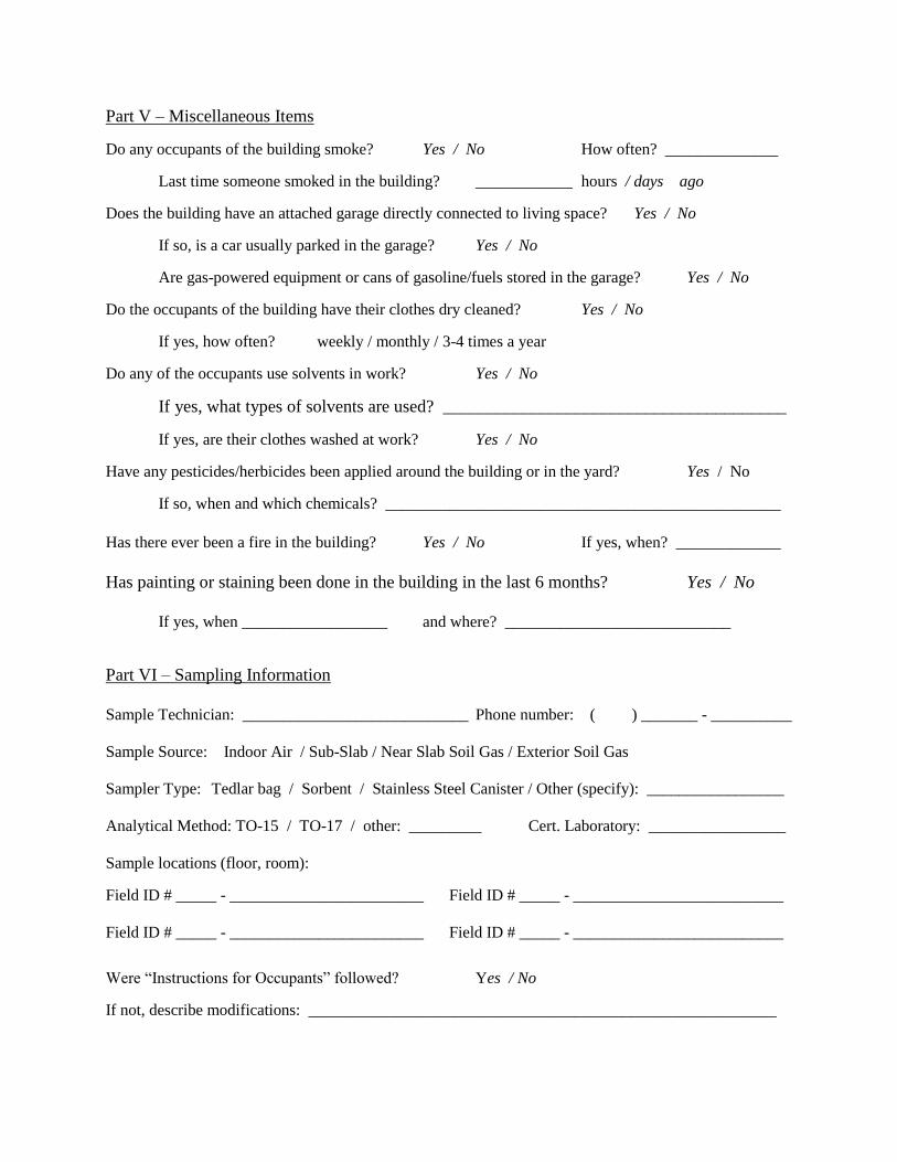
Part V – Miscellaneous Items
Do any occupants of the building smoke? Yes / No How often? ______________
Last time someone smoked in the building? ____________ hours / days ago
Does the building have an attached garage directly connected to living space? Yes / No
If so, is a car usually parked in the garage? Yes / No
Are gas-powered equipment or cans of gasoline/fuels stored in the garage? Yes / No
Do the occupants of the building have their clothes dry cleaned? Yes / No
If yes, how often? weekly / monthly / 3-4 times a year
Do any of the occupants use solvents in work? Yes / No
If yes, what types of solvents are used? _______________________________________
If yes, are their clothes washed at work? Yes / No
Have any pesticides/herbicides been applied around the building or in the yard? Yes / No
If so, when and which chemicals? _________________________________________________
Has there ever been a fire in the building? Yes / No If yes, when? _____________
Has painting or staining been done in the building in the last 6 months? Yes / No
If yes, when __________________ and where? ____________________________
Part VI – Sampling Information
Sample Technician: ____________________________ Phone number: ( ) _______ - __________
Sample Source: Indoor Air / Sub-Slab / Near Slab Soil Gas / Exterior Soil Gas
Sampler Type: Tedlar bag / Sorbent / Stainless Steel Canister / Other (specify): _________________
Analytical Method: TO-15 / TO-17 / other: _________ Cert. Laboratory: _________________
Sample locations (floor, room):
Field ID # _____ - ________________________ Field ID # _____ - __________________________
Field ID # _____ - ________________________ Field ID # _____ - __________________________
Were “Instructions for Occupants” followed? Yes / No
If not, describe modifications: __________________________________________________________

Provide Drawing of Sample Location(s) in Building
Part VII - Meteorological Conditions
Was there significant precipitation within 12 hours prior to (or during) the sampling event? Yes / No
Describe the general weather conditions: ___________________________________________________
_____________________________________________________________________________________
Part VIII – General Observations
Provide any information that may be pertinent to the sampling event and may assist in the data
interpretation process.
(NJDEP 1997; NHDES 1998; VDOH 1993; MassDEP 2002; NYSDOH 2005; CalEPA 2005)

APPENDIX C
Instructions for Occupants - Indoor Air
Sampling Events (English and Spanish)
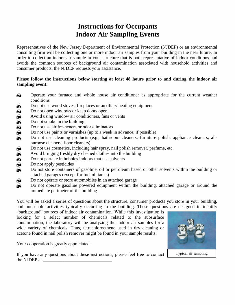
Instructions for Occupants
Indoor Air Sampling Events Representatives of the New Jersey Department of Environmental Protection (NJDEP) or an environmental
consulting firm will be collecting one or more indoor air samples from your building in the near future. In
order to collect an indoor air sample in your structure that is both representative of indoor conditions and
avoids the common sources of background air contamination associated with household activities and
consumer products, the NJDEP requests your assistance.
Please follow the instructions below starting at least 48 hours prior to and during the indoor air
sampling event:
Operate your furnace and whole house air conditioner as appropriate for the current weather
conditions
Do not use wood stoves, fireplaces or auxiliary heating equipment
Do not open windows or keep doors open.
Avoid using window air conditioners, fans or vents
Do not smoke in the building
Do not use air fresheners or odor eliminators
Do not use paints or varnishes (up to a week in advance, if possible)
Do not use cleaning products (e.g., bathroom cleaners, furniture polish, appliance cleaners, all-
purpose cleaners, floor cleaners)
Do not use cosmetics, including hair spray, nail polish remover, perfume, etc.
Avoid bringing freshly dry cleaned clothes into the building
Do not partake in hobbies indoors that use solvents
Do not apply pesticides
Do not store containers of gasoline, oil or petroleum based or other solvents within the building or
attached garages (except for fuel oil tanks)
Do not operate or store automobiles in an attached garage
Do not operate gasoline powered equipment within the building, attached garage or around the
immediate perimeter of the building
You will be asked a series of questions about the structure, consumer products you store in your building,
and household activities typically occurring in the building. These questions are designed to identify
“background” sources of indoor air contamination. While this investigation is
looking for a select number of chemicals related to the subsurface
contamination, the laboratory will be analyzing the indoor air samples for a
wide variety of chemicals. Thus, tetrachloroethene used in dry cleaning or
acetone found in nail polish remover might be found in your sample results.
Your cooperation is greatly appreciated.
If you have any questions about these instructions, please feel free to contact
the NJDEP at ______________________________.
Typical air sampling
canister
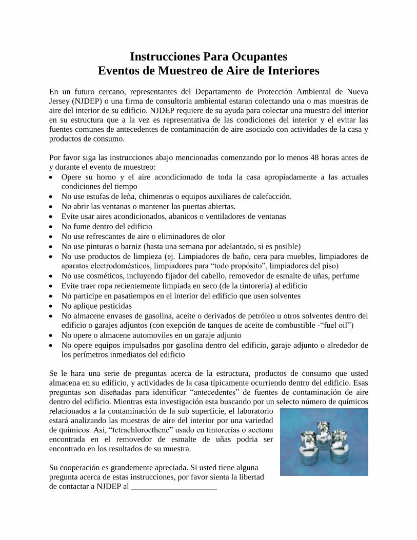
Instrucciones Para Ocupantes
Eventos de Muestreo de Aire de Interiores
En un futuro cercano, representantes del Departamento de Protección Ambiental de Nueva
Jersey (NJDEP) o una firma de consultoria ambiental estaran colectando una o mas muestras de
aire del interior de su edificio. NJDEP requiere de su ayuda para colectar una muestra del interior
en su estructura que a la vez es representativa de las condiciones del interior y el evitar las
fuentes comunes de antecedentes de contaminación de aire asociado con actividades de la casa y
productos de consumo.
Por favor siga las instrucciones abajo mencionadas comenzando por lo menos 48 horas antes de
y durante el evento de muestreo:
• Opere su horno y el aire acondicionado de toda la casa apropiadamente a las actuales
condiciones del tiempo
• No use estufas de leña, chimeneas o equipos auxiliares de calefacción.
• No abrir las ventanas o mantener las puertas abiertas.
• Evite usar aires acondicionados, abanicos o ventiladores de ventanas
• No fume dentro del edificio
• No use refrescantes de aire o eliminadores de olor
• No use pinturas o barniz (hasta una semana por adelantado, si es posible)
• No use productos de limpieza (ej. Limpiadores de baño, cera para muebles, limpiadores de
aparatos electrodomésticos, limpiadores para “todo propósito”, limpiadores del piso)
• No use cosméticos, incluyendo fijador del cabello, removedor de esmalte de uñas, perfume
• Evite traer ropa recientemente limpiada en seco (de la tintorería) al edificio
• No participe en pasatiempos en el interior del edificio que usen solventes
• No aplique pesticidas
• No almacene envases de gasolina, aceite o derivados de petróleo u otros solventes dentro del
edificio o garajes adjuntos (con exepción de tanques de aceite de combustible -“fuel oil”)
• No opere o almacene automoviles en un garaje adjunto
• No opere equipos impulsados por gasolina dentro del edificio, garaje adjunto o alrededor de
los perímetros inmediatos del edificio
Se le hara una serie de preguntas acerca de la estructura, productos de consumo que usted
almacena en su edificio, y actividades de la casa típicamente ocurriendo dentro del edificio. Esas
preguntas son diseñadas para identificar “antecedentes” de fuentes de contaminación de aire
dentro del edificio. Mientras esta investigación esta buscando por un selecto número de químicos
relacionados a la contaminación de la sub superficie, el laboratorio
estará analizando las muestras de aire del interior por una variedad
de químicos. Así, “tetrachloroethene” usado en tintorerías o acetona
encontrada en el removedor de esmalte de uñas podria ser
encontrado en los resultados de su muestra.
Su cooperación es grandemente apreciada. Si usted tiene alguna
pregunta acerca de estas instrucciones, por favor sienta la libertad
de contactar a NJDEP al _____________________

APPENDIX D
Evaluating Indoor Air Near VOC
Contaminated Sites Fact Sheet
APPENDIX E
Subsurface Depressurization Systems
Fact Sheet

APPENDIX F
Background Volatile Levels in homes:
Literature Review

F-1
BACKGROUND VOLATILE LEVELS IN HOMES:
LITERATURE REVIEW
Introduction
A literature review was conducted in June 2002 to determine available information regarding
background levels of volatile compounds in homes and other structures. Over the last twenty
years, several studies have been conducted to determine personal exposures to these chemicals.
Most of them used personal air monitors that added up exposures from all locations visited by
the subjects. However, many of these studies also included dedicated indoor air sampling where
measurements were taken in an indoor fixed location. Most of these studies were done in urban
areas throughout the United States, but some studies were conducted in other countries. In total,
over 1000 homes were sampled. While small contributions from outdoor air concentrations of
volatiles can occur, indoor levels are frequently much higher due to indoor sources of these
chemicals. Therefore, the results from these various studies indicate the range of expected
volatile concentrations resulting from the use of consumer products, the presence of home
furnishings, building materials, and activities such as smoking and cooking. While it is possible
that some of these studies may have inadvertently included a few homes that were located above
soil or groundwater contaminated with volatiles, the likelihood of this is small. For this literature
survey, median and 90th percentile, and maximum levels of measured concentrations were
compiled, the first two of which would largely eliminate the effect of outlier concentrations from
homes located above contaminated soil or groundwater.
Because most of these studies were designed as personal air monitoring studies, they employed
compact sampling devices that could be worn by the subject. Either adsorbent cartridges or
passive adsorption badges were typically used. The adsorbent cartridge technique requires a
small pump to pass air through the cartridge, while passive adsorption badges rely on a
concentration-dependant mass flux of chemical through a stagnant air layer. Both of these
techniques require extraction of the adsorptive medium and analysis of the subsequent extract.
These techniques are different from the typical air sampling technique (SUMMA® canister).
However, all three have been useful for determining indoor air concentrations. Studies included
F-2
in this review were those for which median, 90th percentile, or maximum volatile concentrations
were reported.
TEAM (Total Exposure Assessment Methodology)
The Total Exposure Assessment Methodology study (TEAM) was conducted in the 1980s
(USEPA 1987; Wallace 1987; Wallace, et al. 1985). The study included sampling of 347 homes
in New Jersey (Bayonne and Elizabeth), 183 homes in California (Los Angeles, Antioch, and
Pittsburgh), 24 homes in Greensboro, North Carolina, and 23 homes from Devils Lake, North
Dakota. Many of the New Jersey and California homes were sampled two or more times. The
study employed personal air monitors using Tenax cartridges, and samples taken from 6 pm-6
am were taken as indoor air samples, since most subjects (85% of New Jersey subjects) remained
indoors during this time.
NHEXAS (National Human Exposure Assessment Survey)
The National Human Exposure Assessment Survey (NHEXAS) study was conducted in the
1990s (Clayton et al. 1999; Gordon et al. 1999; Bonanno 2000). The study included sampling of
248 homes in the Midwest (Illinois, Indiana, Michigan, Minnesota, Ohio and Wisconsin) and
185 homes in Arizona. Several of the Midwest homes were sampled twice. The study employed
passive vapor monitors (3M Organic Vapor Monitors) that were left indoors at a fixed location
for 6 days.
RIOPA (Relationship of Indoor, Outdoor and Personal Air
A study entitled Relationship of Indoor, Outdoor and Personal Air (RIOPA) is currently in
progress (Weisel et al. 2001; Zhang et al. 2001). The project design entails twice sampling 100
homes in each of three urban centers. Preliminary results from one of these centers (Elizabeth,
New Jersey) are currently available. This study also employs passive vapor monitors (3M
Organic Vapor Monitors) that were left in place for a 48-hour period. Houses with smokers were
excluded.
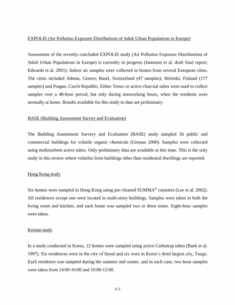
F-3
EXPOLIS (Air Pollution Exposure Distributions of Adult Urban Populations in Europe)
Assessment of the recently concluded EXPOLIS study (Air Pollution Exposure Distributions of
Adult Urban Populations in Europe) is currently in progress (Jantunen et al. draft final report;
Edwards et al. 2001). Indoor air samples were collected in homes from several European cities.
The cities included Athens, Greece; Basel, Switzerland (47 samples); Helsinki, Finland (177
samples) and Prague, Czech Republic. Either Tenax or active charcoal tubes were used to collect
samples over a 48-hour period, but only during nonworking hours, when the residents were
normally at home. Results available for this study to date are preliminary.
BASE (Building Assessment Survey and Evaluation)
The Building Assessment Survery and Evaluation (BASE) study sampled 56 public and
commercial buildings for volatile organic chemicals (Girman 2000). Samples were collected
using multisorbent active tubes. Only preliminary data are available at this time. This is the only
study in this review where volatiles from buildings other than residential dwellings are reported.
Hong Kong study
Six homes were sampled in Hong Kong using pre-cleaned SUMMA® canisters (Lee et al. 2002).
All residences except one were located in multi-story buildings. Samples were taken in both the
living room and kitchen, and each home was sampled two or three times. Eight-hour samples
were taken.
Korean study
In a study conducted in Korea, 12 homes were sampled using active Carbotrap tubes (Baek et al.
1997). Six residences were in the city of Seoul and six were in Korea’s third largest city, Taegu.
Each residence was sampled during the summer and winter, and in each case, two-hour samples
were taken from 14:00-16:00 and 10:00-12:00.
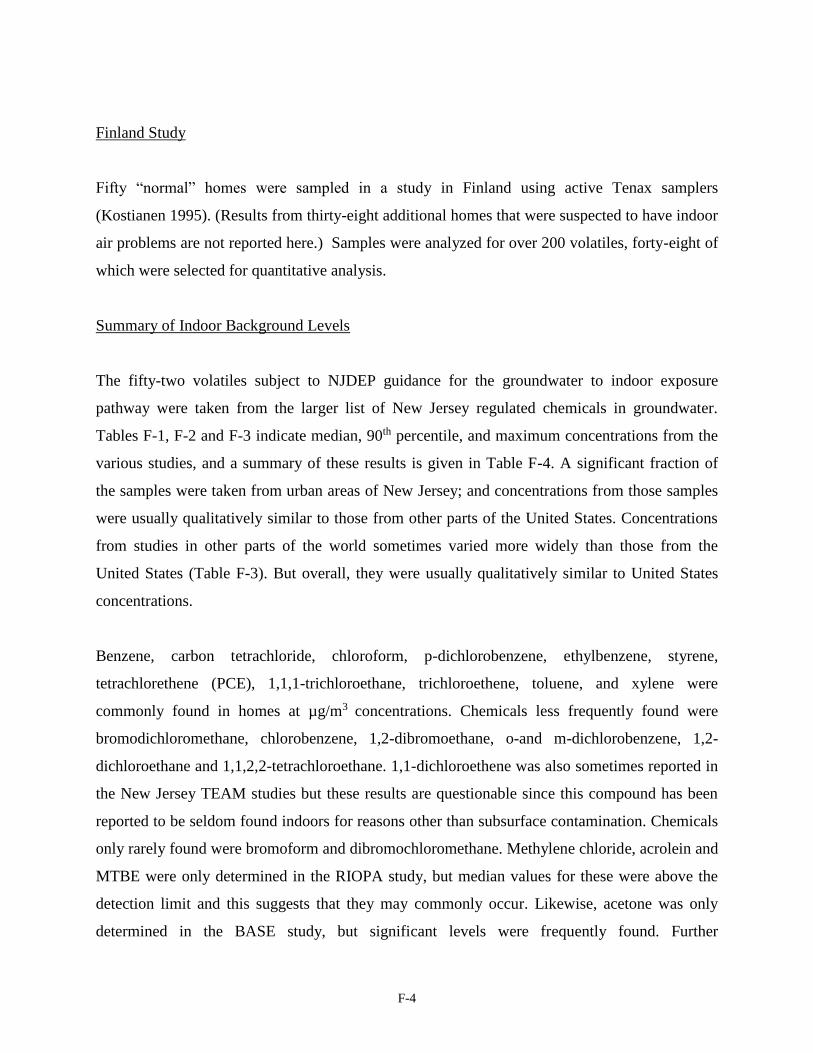
F-4
Finland Study
Fifty “normal” homes were sampled in a study in Finland using active Tenax samplers
(Kostianen 1995). (Results from thirty-eight additional homes that were suspected to have indoor
air problems are not reported here.) Samples were analyzed for over 200 volatiles, forty-eight of
which were selected for quantitative analysis.
Summary of Indoor Background Levels
The fifty-two volatiles subject to NJDEP guidance for the groundwater to indoor exposure
pathway were taken from the larger list of New Jersey regulated chemicals in groundwater.
Tables F-1, F-2 and F-3 indicate median, 90th percentile, and maximum concentrations from the
various studies, and a summary of these results is given in Table F-4. A significant fraction of
the samples were taken from urban areas of New Jersey; and concentrations from those samples
were usually qualitatively similar to those from other parts of the United States. Concentrations
from studies in other parts of the world sometimes varied more widely than those from the
United States (Table F-3). But overall, they were usually qualitatively similar to United States
concentrations.
Benzene, carbon tetrachloride, chloroform, p-dichlorobenzene, ethylbenzene, styrene,
tetrachlorethene (PCE), 1,1,1-trichloroethane, trichloroethene, toluene, and xylene were
commonly found in homes at µg/m3 concentrations. Chemicals less frequently found were
bromodichloromethane, chlorobenzene, 1,2-dibromoethane, o-and m-dichlorobenzene, 1,2-
dichloroethane and 1,1,2,2-tetrachloroethane. 1,1-dichloroethene was also sometimes reported in
the New Jersey TEAM studies but these results are questionable since this compound has been
reported to be seldom found indoors for reasons other than subsurface contamination. Chemicals
only rarely found were bromoform and dibromochloromethane. Methylene chloride, acrolein and
MTBE were only determined in the RIOPA study, but median values for these were above the
detection limit and this suggests that they may commonly occur. Likewise, acetone was only
determined in the BASE study, but significant levels were frequently found. Further
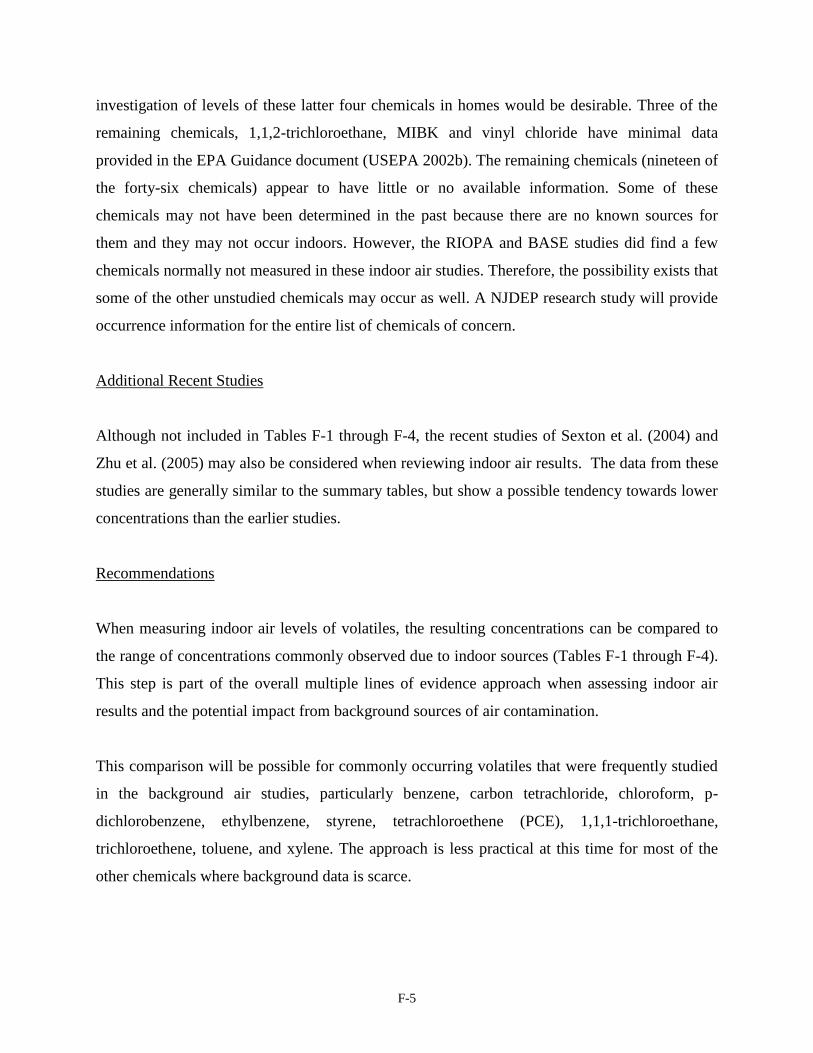
F-5
investigation of levels of these latter four chemicals in homes would be desirable. Three of the
remaining chemicals, 1,1,2-trichloroethane, MIBK and vinyl chloride have minimal data
provided in the EPA Guidance document (USEPA 2002b). The remaining chemicals (nineteen of
the forty-six chemicals) appear to have little or no available information. Some of these
chemicals may not have been determined in the past because there are no known sources for
them and they may not occur indoors. However, the RIOPA and BASE studies did find a few
chemicals normally not measured in these indoor air studies. Therefore, the possibility exists that
some of the other unstudied chemicals may occur as well. A NJDEP research study will provide
occurrence information for the entire list of chemicals of concern.
Additional Recent Studies
Although not included in Tables F-1 through F-4, the recent studies of Sexton et al. (2004) and
Zhu et al. (2005) may also be considered when reviewing indoor air results. The data from these
studies are generally similar to the summary tables, but show a possible tendency towards lower
concentrations than the earlier studies.
Recommendations
When measuring indoor air levels of volatiles, the resulting concentrations can be compared to
the range of concentrations commonly observed due to indoor sources (Tables F-1 through F-4).
This step is part of the overall multiple lines of evidence approach when assessing indoor air
results and the potential impact from background sources of air contamination.
This comparison will be possible for commonly occurring volatiles that were frequently studied
in the background air studies, particularly benzene, carbon tetrachloride, chloroform, p-
dichlorobenzene, ethylbenzene, styrene, tetrachloroethene (PCE), 1,1,1-trichloroethane,
trichloroethene, toluene, and xylene. The approach is less practical at this time for most of the
other chemicals where background data is scarce.
APPENDIX G
Derivation of the
Generic Screening Levels
G-1
DERIVATION OF THE GENERIC SCREENING LEVELS
The basis for the development of the Ground Water Screening Levels (GWSL), Indoor Air
Screening Levels (IASL), and Soil Gas Screening Levels (SGSL) listed in Table 1 is presented
below. As discussed in Chapter 4, the screening levels are to be used in the evaluation of a site
for the vapor intrusion (VI) pathway.
1.0 DETERMINATION OF THE LIST OF VOLATILE ORGANIC
CHEMICALS
VI is a potential concern when soil, soil gas or ground water is contaminated with volatile
organic compounds (VOC) since volatile vapors may readily migrate through the subsurface into
building basements and living areas. The USEPA Draft Vapor Intrusion Guidance (USEPA
2002b) defines VOC as chemicals with a Henry’s Law constant greater than or equal to 1 x 10⁻⁵
atm m-3 mol-1 at room temperature. A chemical’s Henry’s Law constant is approximately equal
to the ratio of the chemical’s vapor pressure divided by its water solubility. Thus, the Henry’s
Law constant takes into account a chemical’s most fundamental measure of volatility (vapor
pressure) and its tendency to volatilize from water. Chemicals with high Henry’s Law constants
are those with relatively high vapor pressures and relatively low water solubilities.
The use of Henry’s Law criteria alone in the evaluation of potential VI can lead to anomalous
results. For example, the USEPA Draft Vapor Intrusion Guidance lists p,p-
dichlorodiphenyldichloroethylene (DDE), dieldrin and di-n-octyl phthalate as VOC. These
chemicals are not identified as VOC by the Department since they have low vapor pressures and
are highly adsorbed to soil. In contrast, chemicals commonly viewed as VOC (benzene,
trichloroethylene, etc.) typically are liquids, have vapor pressures of several hundred to several
thousand mm Hg at room temperature, and are weakly adsorbed to soil (Koc values of 10-1000
ml/g). Borderline volatile chemicals, such as dichlorobenzene and trimethylbenzenes, may have
vapor pressures between 1 and 10 mm Hg. Since the vapor pressure of a chemical is the most
fundamental measure of volatility, the Department is applying vapor pressure as a secondary
G-2
parameter in the definition of a VOC. Consideration of the vapor pressure in the definition is also
compatible with current VOC analytical methods, which do not include low vapor pressure
chemicals, such as those discussed above. The Department is therefore considering a chemical to
be volatile if its Henry’s law constant is greater than 10-5 atm m-3 mol-1 and its vapor pressure is
greater than 1 mm Hg at room temperature.
The VOC with screening levels listed in this document are based on the chemicals included in
the Department’s state contract for USEPA Method TO-15 (NJDEP 2003b; NJDEP 2003c).
Consideration of those chemicals listed in the USEPA TO-15 analytical method in the evaluation
of the VI pathway is necessary since some chemicals considered VOC are not readily analyzed
using currently available and standard analytical methods. The above definition used to
determine the VOC chemicals of concern for the pathway resulted in the removal of the
anomalous chemicals discussed previously that are included in the USEPA Draft Vapor Intrusion
Guidance. Tert-butyl alcohol (TBA) is the only chemical on New Jersey’s TO-15 list that fails
the Henry’s law constant criteria, with a value of 9.0E-06 atm m-3 mol-1. However, this value is
very close to the 10-5 cutoff and its vapor pressure (40 mm Hg) meets the vapor pressure cutoff.
TBA is also an important gasoline additive associated with leaking underground storage tanks.
TBA has, therefore, been included in the list of chemicals and is considered a VOC.
Two other USEPA Method TO-15 chemicals (hexachlorobutadiene and 1,2,4-trichlorobenzene)
meet the Henry’s Law constant criteria but do not meet the vapor pressure criteria, with vapor
pressures of 0.22 mm Hg and 0.46 mm Hg, respectively. These values, however, are close to the
1 mm Hg cutoff criteria, and are sufficiently volatile to be analyzed by USEPA Method TO-15.
The chemicals have, therefore, been included on the list of chemicals in this guidance.
Additional volatile compounds will be added to the list in future updates to the document based
on new information and modifications pertaining to the VOC analytical methods.
1.1 Rounding of the Screening Level Values
The screening level values have been rounded to 2 significant figures for a value greater than or
equal to 10, and to 1 significant figure for a value less than 10, including those less than 1. This
G-3
approach is used by the USEPA Office of Solid Waste and Emergency Response and is
described in the Supplemental Guidance for Developing Soil Screening Levels for Superfund
Sites, (USEPA 2001a). The rounding rules specified below are contained in Hurlbert (1994).
The screening levels and analytical reporting limits were rounded as follows:
• If the first number beyond the last significant digit is less than 5, the last significant number
remains the same; and the remaining numbers are dropped. For example, 4.438 is rounded to
one significant figure, 4; and 44.38 is rounded to 2 significant figures, 44.
• If the first number beyond the last significant digit is more than 5, the last significant number
increases by one and the remaining numbers are dropped. For example, 4.638 is rounded to
one significant figure, 5; and 46.68 is rounded to 2 significant figures, 47.
• If the first number beyond the last significant digit is exactly 5, then the last digit is rounded
to the closest even number. For example, 4.5 is rounded to one significant figure, 4; and 45.5
is rounded to two significant figures, 46.
2.0 GROUND WATER SCREENING LEVELS
To develop the screening levels, the Department evaluated the USEPA Draft Vapor Intrusion
Guidance (USEPA 2002b). The USEPA Draft Vapor Intrusion Guidance calculates screening
levels using indoor air criteria, the Henry’s law constant for the chemical, and an assumed
dilution attenuation factor of 1 x 10⁻³ between the ground water and indoor air (USEPA 2002b).
This approach was found to be protective of 95% of the residences studied where paired ground
water and indoor air measurements were available.
An alternate approach is to use the J&E model to calculate ground water screening levels
(Johnson and Ettinger 1991; USEPA 2002b). This approach is somewhat more rigorous, in that it
calculates chemical specific dilution attenuation factors, which vary according to chemical
properties such as diffusivity and the Henry’s law constant. Additionally, a series of spreadsheets
for evaluating the J&E model has recently been released by the USEPA that allows adjustment
G-4
of the Henry’s law constant for the ground water temperature (USEPA 2004d). The simpler
method described in the USEPA Draft Vapor Intrusion Guidance uses Henry’s law constants at a
temperature of 25°C, which is considerably higher than ground water temperatures in New
Jersey. New Jersey ground water temperatures typically range from 10-15°C (United States
Geological Survey, 2003). A lower ground water temperature reduces the Henry’s law constant.
This reduces the source vapor concentration and moderately raises the ground water screening
level. Screening levels calculated using the J&E model compare favorably with the simpler
USEPA approach (USEPA 2002b), and it has been used successfully by several other states for
calculation of screening levels for the VI pathway (Connecticut, Massachusetts, Michigan).
Therefore, this model was utilized by the Department with New Jersey specific factors (where
appropriate) instead of the simple USEPA approach for calculation of the GWSL.
The J&E model assumes contaminants volatilize from the surface of the water table in
accordance with Henry’s law. Contaminants then diffuse through the capillary zone of the soil
column and the unsaturated soil zone, as controlled by air and water diffusion coefficients, the
Henry’s law constant, and soil properties (soil texture, soil moisture content, soil porosity). Upon
nearing a building foundation, contaminants enter a zone of influence where soil gas advection
and/or convection may occur, which may then transport the contaminant into a structure of
concern via bulk soil gas flow. The magnitude of this transport is dependent on the magnitude of
building depressurization, if any, and the extent of openings in the building foundation (e.g.
cracks in the foundation slab and the magnitude of the crack size between the foundation slab
and the foundation wall). In some cases, building depressurization may be minimal or absent,
and contaminants will diffuse through these openings via diffusion. The J&E model calculates
the relative contribution of each of these transport mechanisms. Contaminants entering the
building are assumed to immediately mix with building interior air. The amount of contaminant
dilution that occurs upon entry into the building depends on the soil gas entry rate, the building
air exchange rate and the building size.
USEPA discusses the various input parameters that are used in the J&E model and provides
recommended quantitative values for them based on the most current information available in the
USEPA Draft Vapor Intrusion Guidance (USEPA 2002b). In 2003, the USEPA released several

G-5
EXCEL spreadsheets incorporating various versions of the J&E Model (USEPA 2004d). These
spreadsheets incorporate the current recommended parameter values. The screening spreadsheet
(GW-SCREEN) was used by the Department to calculate ground water screening levels for the
VI pathway.
In accordance with departmental policy, when calculated health-based screening values are
below the current New Jersey Ground Water Quality Standards (GWQS), the screening levels
are set at the higher GWQS instead of the calculated values. Table G-1 presents the calculated
health-based screening values and the applicable GWQS. Table 1 presents the GWSL after
consideration of the calculated values and the GWQS.
2.1 Input Parameters for the Johnson and Ettinger (J&E) Model
Input parameter values used in the development of the ground water screening levels presented
in Table G-1 were largely adopted as per USEPA recommendation, with the exception of ground
water temperature. For the sensitivity analyses discussed below, all parameters except the one
under study were held at the base value.
2.1.1 Soil Texture
Soil texture should be specified in the J&E spreadsheet and has a large effect on contaminant
diffusion rates through the capillary zone and the unsaturated soil zone. The calculated Ground
Water Screening Levels (GWSL) are therefore quite sensitive to this parameter. Sandy soil is
common in much of the southern half of New Jersey (Tedrow 1986). This soil texture results in
the most conservative estimates of ground water screening levels for the VI pathway, since
heavier soil types (sandy loam, loam, etc.) provide more resistance to contaminant diffusion
through the soil column. Additionally, the USEPA generic ground water screening levels use an
attenuation factor of 1 x 10⁻³, which corresponds to the approximate attenuation factor calculated
using the J&E model with sand soil. Therefore, this soil texture was selected for development of
GWSL, and was used in all locations in the spreadsheet where a soil texture was required (soil
texture just above water table, soil texture in vadose zone for estimation of soil physicochemical
properties, and soil texture to estimate soil permeability).
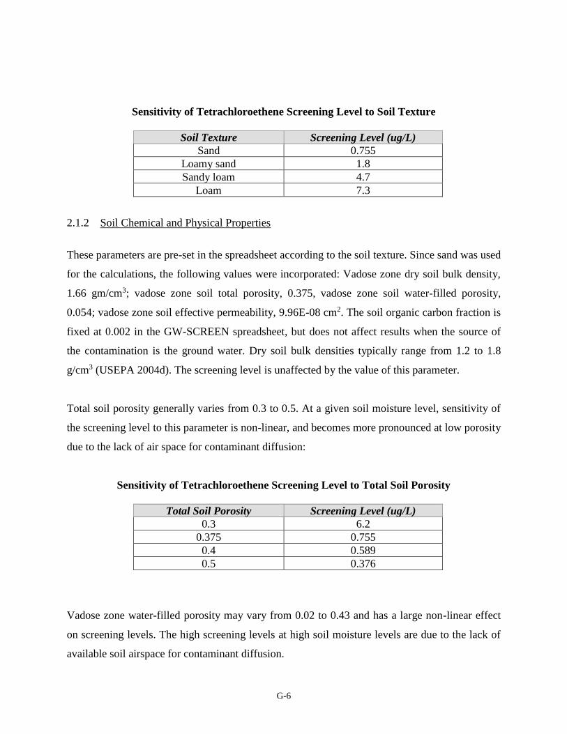
G-6
Sensitivity of Tetrachloroethene Screening Level to Soil Texture
Soil Texture Screening Level (ug/L)
Sand 0.755
Loamy sand 1.8
Sandy loam 4.7
Loam 7.3
2.1.2 Soil Chemical and Physical Properties
These parameters are pre-set in the spreadsheet according to the soil texture. Since sand was used
for the calculations, the following values were incorporated: Vadose zone dry soil bulk density,
1.66 gm/cm3; vadose zone soil total porosity, 0.375, vadose zone soil water-filled porosity,
0.054; vadose zone soil effective permeability, 9.96E-08 cm2. The soil organic carbon fraction is
fixed at 0.002 in the GW-SCREEN spreadsheet, but does not affect results when the source of
the contamination is the ground water. Dry soil bulk densities typically range from 1.2 to 1.8
g/cm3 (USEPA 2004d). The screening level is unaffected by the value of this parameter.
Total soil porosity generally varies from 0.3 to 0.5. At a given soil moisture level, sensitivity of
the screening level to this parameter is non-linear, and becomes more pronounced at low porosity
due to the lack of air space for contaminant diffusion:
Sensitivity of Tetrachloroethene Screening Level to Total Soil Porosity
Total Soil Porosity Screening Level (ug/L)
0.3 6.2
0.375 0.755
0.4 0.589
0.5 0.376
Vadose zone water-filled porosity may vary from 0.02 to 0.43 and has a large non-linear effect
on screening levels. The high screening levels at high soil moisture levels are due to the lack of
available soil airspace for contaminant diffusion.
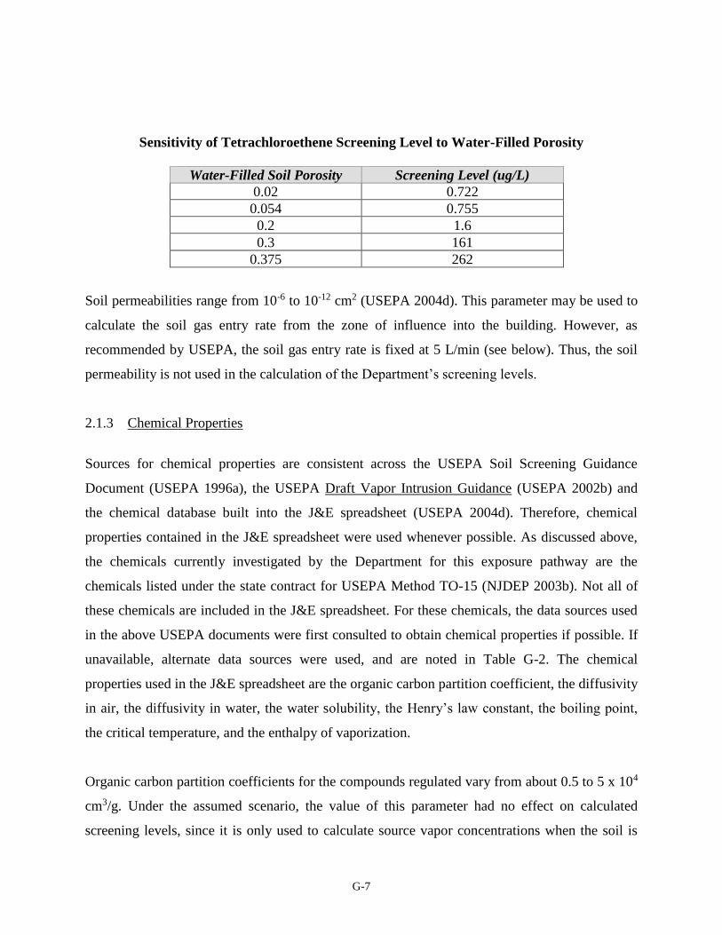
G-7
Sensitivity of Tetrachloroethene Screening Level to Water-Filled Porosity
Water-Filled Soil Porosity Screening Level (ug/L)
0.02 0.722
0.054 0.755
0.2 1.6
0.3 161
0.375 262
Soil permeabilities range from 10-6 to 10-12 cm2 (USEPA 2004d). This parameter may be used to
calculate the soil gas entry rate from the zone of influence into the building. However, as
recommended by USEPA, the soil gas entry rate is fixed at 5 L/min (see below). Thus, the soil
permeability is not used in the calculation of the Department’s screening levels.
2.1.3 Chemical Properties
Sources for chemical properties are consistent across the USEPA Soil Screening Guidance
Document (USEPA 1996a), the USEPA Draft Vapor Intrusion Guidance (USEPA 2002b) and
the chemical database built into the J&E spreadsheet (USEPA 2004d). Therefore, chemical
properties contained in the J&E spreadsheet were used whenever possible. As discussed above,
the chemicals currently investigated by the Department for this exposure pathway are the
chemicals listed under the state contract for USEPA Method TO-15 (NJDEP 2003b). Not all of
these chemicals are included in the J&E spreadsheet. For these chemicals, the data sources used
in the above USEPA documents were first consulted to obtain chemical properties if possible. If
unavailable, alternate data sources were used, and are noted in Table G-2. The chemical
properties used in the J&E spreadsheet are the organic carbon partition coefficient, the diffusivity
in air, the diffusivity in water, the water solubility, the Henry’s law constant, the boiling point,
the critical temperature, and the enthalpy of vaporization.
Organic carbon partition coefficients for the compounds regulated vary from about 0.5 to 5 x 10⁴
cm3/g. Under the assumed scenario, the value of this parameter had no effect on calculated
screening levels, since it is only used to calculate source vapor concentrations when the soil is
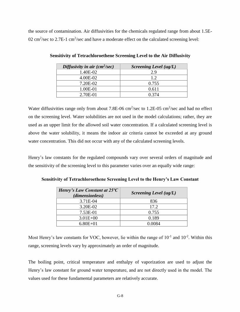
G-8
the source of contamination. Air diffusivities for the chemicals regulated range from about 1.5E-
02 cm2/sec to 2.7E-1 cm2/sec and have a moderate effect on the calculated screening level:
Sensitivity of Tetrachloroethene Screening Level to the Air Diffusivity
Diffusivity in air (cm2/sec) Screening Level (ug/L)
1.40E-02 2.9
4.00E-02 1.2
7.20E-02 0.755
1.00E-01 0.611
2.70E-01 0.374
Water diffusivities range only from about 7.8E-06 cm2/sec to 1.2E-05 cm2/sec and had no effect
on the screening level. Water solubilities are not used in the model calculations; rather, they are
used as an upper limit for the allowed soil water concentration. If a calculated screening level is
above the water solubility, it means the indoor air criteria cannot be exceeded at any ground
water concentration. This did not occur with any of the calculated screening levels.
Henry’s law constants for the regulated compounds vary over several orders of magnitude and
the sensitivity of the screening level to this parameter varies over an equally wide range:
Sensitivity of Tetrachloroethene Screening Level to the Henry’s Law Constant
Henry’s Law Constant at 25ºC
(dimensionless) Screening Level (ug/L)
3.71E-04 836
3.20E-02 17.2
7.53E-01 0.755
3.01E+00 0.189
6.80E+01 0.0084
Most Henry’s law constants for VOC, however, lie within the range of 10-1 and 10-2. Within this
range, screening levels vary by approximately an order of magnitude.
The boiling point, critical temperature and enthalpy of vaporization are used to adjust the
Henry’s law constant for ground water temperature, and are not directly used in the model. The
values used for these fundamental parameters are relatively accurate.

G-9
2.1.4 Chemical Toxicological Properties
USEPA Region III toxicological parameters and assumptions were used to derive ground water
screening numbers (USEPA 2005). The J&E model back-calculates screening values from
allowed inhalation exposures. The required parameters are the unit risk factor (URF) for
carcinogens and the reference concentration (RfC) for noncarcinogens (Table G-3). For a few
parameters, Region III values were not available, and other sources were used. Four chemicals
listed under the Department’s Method TO-15 contract do not have toxicological information
(1,2-dichlorotetrafluoroethane, 4-ethyltoluene, n-heptane, and 2,2,4-trimethylpentane). GWSL
were not calculated for these chemicals.
The screening level is inversely related to the URF (i.e., doubling the URF will cause the
screening level to drop by one-half when the carcinogenic endpoint controls the screening level).
The RfC is linearly related to the screening level (i.e. doubling the RfC doubles the screening
level when the noncarcinogenic endpoint controls the screening level).
2.1.5 Exposure Parameters
USEPA Region III exposure assumptions were used. This includes a target risk level of 10-6 for
carcinogens and a target hazard quotient of 1 for noncarcinogens. These values are also in
accordance with departmental policy. Other exposure assumptions, with one exception, were
consistent across USEPA Region III, the USEPA Soil Screening Guidance and the USEPA Draft
Vapor Intrusion Guidance. These parameter values were: averaging time for carcinogens, 70
years; averaging time for noncarcinogens, 30 years; exposure duration, 30 years; exposure
frequency, 350 days/year. The exception pertains to body weight and inhalation rates during the
exposure period. USEPA Region III includes an exposure adjustment for carcinogens when
determining acceptable air concentrations that factor in the different contact rates of children to
chemical vapors. This adjustment results in a 26% reduction in the GWSL calculated assuming
adult only exposure. Since the J&E spreadsheet cannot make this adjustment, the screening
levels obtained from the spreadsheet were multiplied by 74% to obtain the ground water
screening level when the value was controlled by a carcinogenic endpoint.
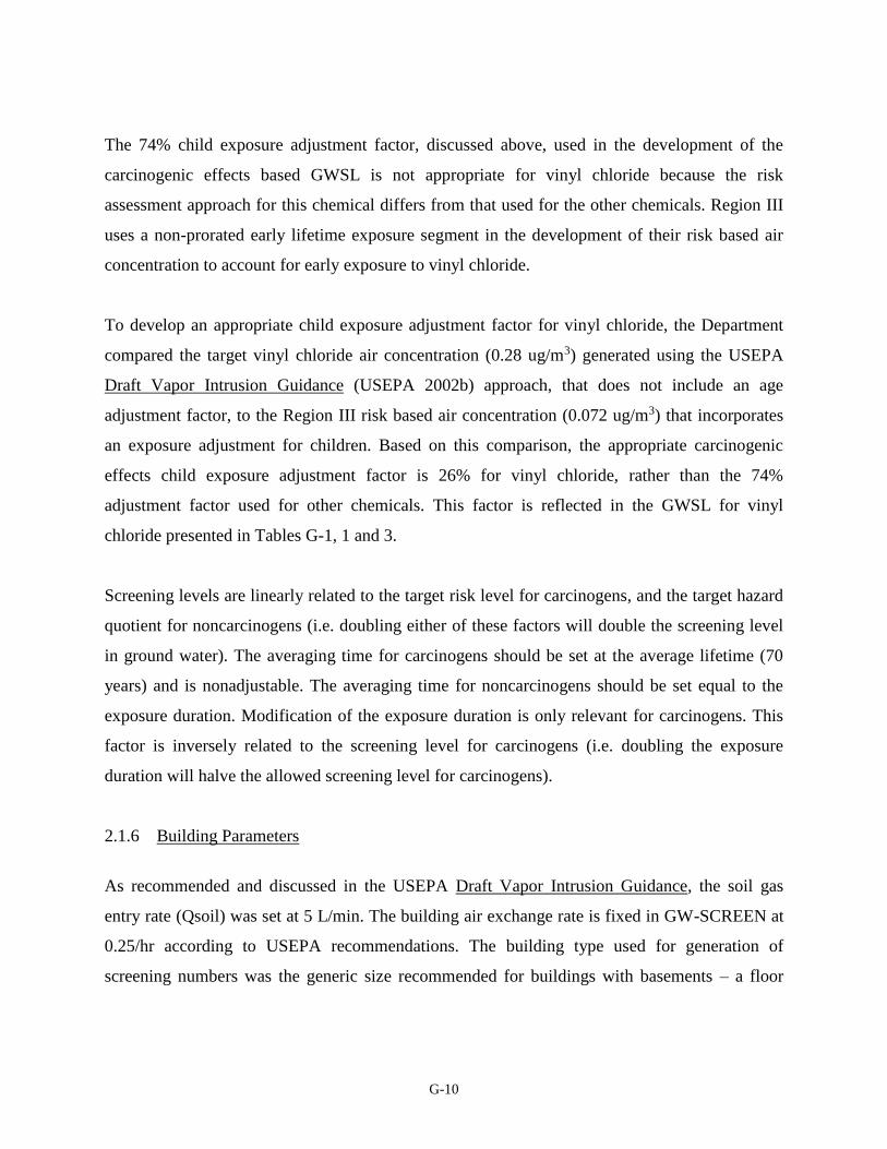
G-10
The 74% child exposure adjustment factor, discussed above, used in the development of the
carcinogenic effects based GWSL is not appropriate for vinyl chloride because the risk
assessment approach for this chemical differs from that used for the other chemicals. Region III
uses a non-prorated early lifetime exposure segment in the development of their risk based air
concentration to account for early exposure to vinyl chloride.
To develop an appropriate child exposure adjustment factor for vinyl chloride, the Department
compared the target vinyl chloride air concentration (0.28 ug/m3) generated using the USEPA
Draft Vapor Intrusion Guidance (USEPA 2002b) approach, that does not include an age
adjustment factor, to the Region III risk based air concentration (0.072 ug/m3) that incorporates
an exposure adjustment for children. Based on this comparison, the appropriate carcinogenic
effects child exposure adjustment factor is 26% for vinyl chloride, rather than the 74%
adjustment factor used for other chemicals. This factor is reflected in the GWSL for vinyl
chloride presented in Tables G-1, 1 and 3.
Screening levels are linearly related to the target risk level for carcinogens, and the target hazard
quotient for noncarcinogens (i.e. doubling either of these factors will double the screening level
in ground water). The averaging time for carcinogens should be set at the average lifetime (70
years) and is nonadjustable. The averaging time for noncarcinogens should be set equal to the
exposure duration. Modification of the exposure duration is only relevant for carcinogens. This
factor is inversely related to the screening level for carcinogens (i.e. doubling the exposure
duration will halve the allowed screening level for carcinogens).
2.1.6 Building Parameters
As recommended and discussed in the USEPA Draft Vapor Intrusion Guidance, the soil gas
entry rate (Qsoil) was set at 5 L/min. The building air exchange rate is fixed in GW-SCREEN at
0.25/hr according to USEPA recommendations. The building type used for generation of
screening numbers was the generic size recommended for buildings with basements – a floor
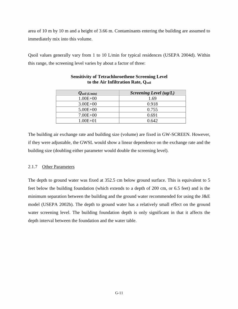
G-11
area of 10 m by 10 m and a height of 3.66 m. Contaminants entering the building are assumed to
immediately mix into this volume.
Qsoil values generally vary from 1 to 10 L/min for typical residences (USEPA 2004d). Within
this range, the screening level varies by about a factor of three:
Sensitivity of Tetrachloroethene Screening Level
to the Air Infiltration Rate, Qsoil
Qsoil (L/min) Screening Level (ug/L)
1.00E+00 1.69
3.00E+00 0.918
5.00E+00 0.755
7.00E+00 0.691
1.00E+01 0.642
The building air exchange rate and building size (volume) are fixed in GW-SCREEN. However,
if they were adjustable, the GWSL would show a linear dependence on the exchange rate and the
building size (doubling either parameter would double the screening level).
2.1.7 Other Parameters
The depth to ground water was fixed at 352.5 cm below ground surface. This is equivalent to 5
feet below the building foundation (which extends to a depth of 200 cm, or 6.5 feet) and is the
minimum separation between the building and the ground water recommended for using the J&E
model (USEPA 2002b). The depth to ground water has a relatively small effect on the ground
water screening level. The building foundation depth is only significant in that it affects the
depth interval between the foundation and the water table.
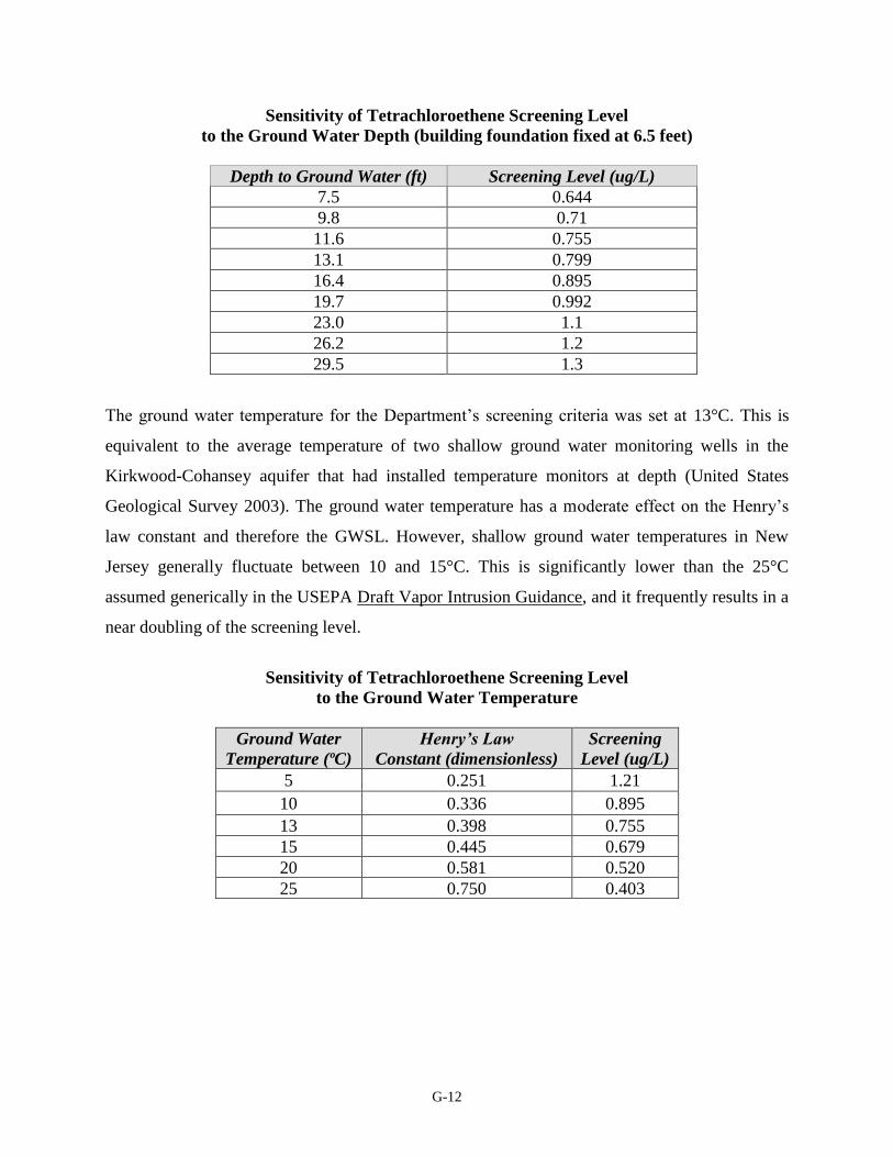
G-12
Sensitivity of Tetrachloroethene Screening Level
to the Ground Water Depth (building foundation fixed at 6.5 feet)
Depth to Ground Water (ft) Screening Level (ug/L)
7.5 0.644
9.8 0.71
11.6 0.755
13.1 0.799
16.4 0.895
19.7 0.992
23.0 1.1
26.2 1.2
29.5 1.3
The ground water temperature for the Department’s screening criteria was set at 13°C. This is
equivalent to the average temperature of two shallow ground water monitoring wells in the
Kirkwood-Cohansey aquifer that had installed temperature monitors at depth (United States
Geological Survey 2003). The ground water temperature has a moderate effect on the Henry’s
law constant and therefore the GWSL. However, shallow ground water temperatures in New
Jersey generally fluctuate between 10 and 15°C. This is significantly lower than the 25°C
assumed generically in the USEPA Draft Vapor Intrusion Guidance, and it frequently results in a
near doubling of the screening level.
Sensitivity of Tetrachloroethene Screening Level
to the Ground Water Temperature
Ground Water
Temperature (ºC)
Henry’s Law
Constant (dimensionless)
Screening
Level (ug/L)
5 0.251 1.21
10 0.336 0.895
13 0.398 0.755
15 0.445 0.679
20 0.581 0.520
25 0.750 0.403
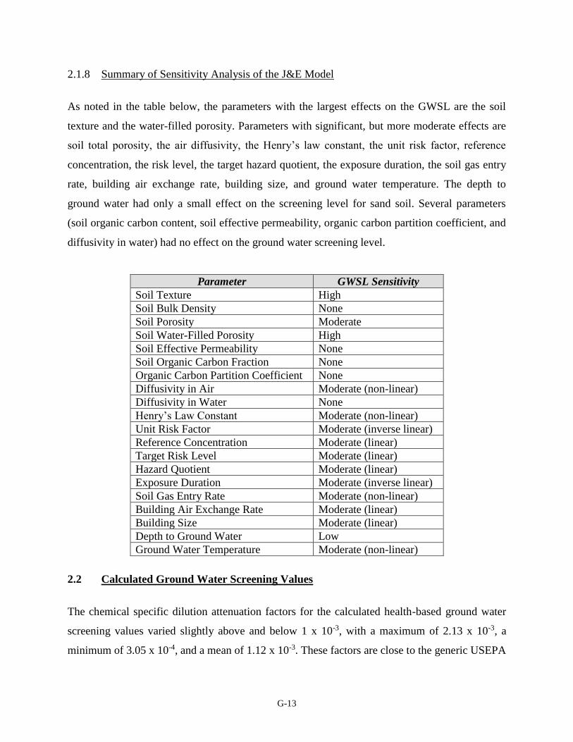
G-13
2.1.8 Summary of Sensitivity Analysis of the J&E Model
As noted in the table below, the parameters with the largest effects on the GWSL are the soil
texture and the water-filled porosity. Parameters with significant, but more moderate effects are
soil total porosity, the air diffusivity, the Henry’s law constant, the unit risk factor, reference
concentration, the risk level, the target hazard quotient, the exposure duration, the soil gas entry
rate, building air exchange rate, building size, and ground water temperature. The depth to
ground water had only a small effect on the screening level for sand soil. Several parameters
(soil organic carbon content, soil effective permeability, organic carbon partition coefficient, and
diffusivity in water) had no effect on the ground water screening level.
Parameter GWSL Sensitivity
Soil Texture High
Soil Bulk Density None
Soil Porosity Moderate
Soil Water-Filled Porosity High
Soil Effective Permeability None
Soil Organic Carbon Fraction None
Organic Carbon Partition Coefficient None
Diffusivity in Air Moderate (non-linear)
Diffusivity in Water None
Henry’s Law Constant Moderate (non-linear)
Unit Risk Factor Moderate (inverse linear)
Reference Concentration Moderate (linear)
Target Risk Level Moderate (linear)
Hazard Quotient Moderate (linear)
Exposure Duration Moderate (inverse linear)
Soil Gas Entry Rate Moderate (non-linear)
Building Air Exchange Rate Moderate (linear)
Building Size Moderate (linear)
Depth to Ground Water Low
Ground Water Temperature Moderate (non-linear)
2.2 Calculated Ground Water Screening Values
The chemical specific dilution attenuation factors for the calculated health-based ground water
screening values varied slightly above and below 1 x 10⁻³, with a maximum of 2.13 x 10⁻³, a
minimum of 3.05 x 10⁻⁴, and a mean of 1.12 x 10⁻³. These factors are close to the generic USEPA
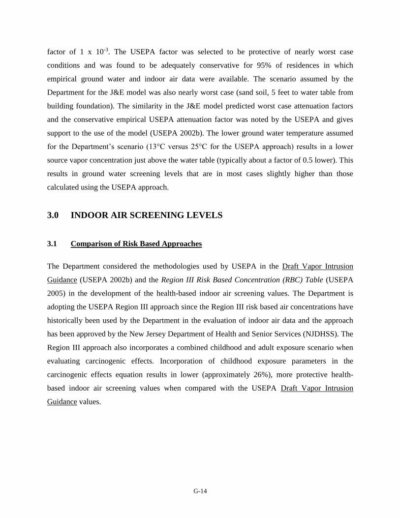
G-14
factor of 1 x 10⁻³. The USEPA factor was selected to be protective of nearly worst case
conditions and was found to be adequately conservative for 95% of residences in which
empirical ground water and indoor air data were available. The scenario assumed by the
Department for the J&E model was also nearly worst case (sand soil, 5 feet to water table from
building foundation). The similarity in the J&E model predicted worst case attenuation factors
and the conservative empirical USEPA attenuation factor was noted by the USEPA and gives
support to the use of the model (USEPA 2002b). The lower ground water temperature assumed
for the Department’s scenario (13°C versus 25°C for the USEPA approach) results in a lower
source vapor concentration just above the water table (typically about a factor of 0.5 lower). This
results in ground water screening levels that are in most cases slightly higher than those
calculated using the USEPA approach.
3.0 INDOOR AIR SCREENING LEVELS
3.1 Comparison of Risk Based Approaches
The Department considered the methodologies used by USEPA in the Draft Vapor Intrusion
Guidance (USEPA 2002b) and the Region III Risk Based Concentration (RBC) Table (USEPA
2005) in the development of the health-based indoor air screening values. The Department is
adopting the USEPA Region III approach since the Region III risk based air concentrations have
historically been used by the Department in the evaluation of indoor air data and the approach
has been approved by the New Jersey Department of Health and Senior Services (NJDHSS). The
Region III approach also incorporates a combined childhood and adult exposure scenario when
evaluating carcinogenic effects. Incorporation of childhood exposure parameters in the
carcinogenic effects equation results in lower (approximately 26%), more protective health-
based indoor air screening values when compared with the USEPA Draft Vapor Intrusion
Guidance values.
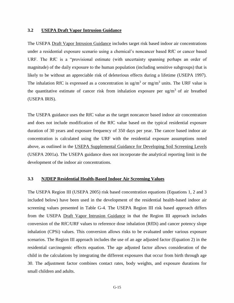
G-15
3.2 USEPA Draft Vapor Intrusion Guidance
The USEPA Draft Vapor Intrusion Guidance includes target risk based indoor air concentrations
under a residential exposure scenario using a chemical’s noncancer based RfC or cancer based
URF. The RfC is a “provisional estimate (with uncertainty spanning perhaps an order of
magnitude) of the daily exposure to the human population (including sensitive subgroups) that is
likely to be without an appreciable risk of deleterious effects during a lifetime (USEPA 1997).
The inhalation RfC is expressed as a concentration in ug/m3 or mg/m3 units. The URF value is
the quantitative estimate of cancer risk from inhalation exposure per ug/m3 of air breathed
(USEPA IRIS).
The USEPA guidance uses the RfC value as the target noncancer based indoor air concentration
and does not include modification of the RfC value based on the typical residential exposure
duration of 30 years and exposure frequency of 350 days per year. The cancer based indoor air
concentration is calculated using the URF with the residential exposure assumptions noted
above, as outlined in the USEPA Supplemental Guidance for Developing Soil Screening Levels
(USEPA 2001a). The USEPA guidance does not incorporate the analytical reporting limit in the
development of the indoor air concentrations.
3.3 NJDEP Residential Health-Based Indoor Air Screening Values
The USEPA Region III (USEPA 2005) risk based concentration equations (Equations 1, 2 and 3
included below) have been used in the development of the residential health-based indoor air
screening values presented in Table G-4. The USEPA Region III risk based approach differs
from the USEPA Draft Vapor Intrusion Guidance in that the Region III approach includes
conversion of the RfC/URF values to reference dose inhalation (RfDi) and cancer potency slope
inhalation (CPSi) values. This conversion allows risks to be evaluated under various exposure
scenarios. The Region III approach includes the use of an age adjusted factor (Equation 2) in the
residential carcinogenic effects equation. The age adjusted factor allows consideration of the
child in the calculations by integrating the different exposures that occur from birth through age
30. The adjustment factor combines contact rates, body weights, and exposure durations for
small children and adults.
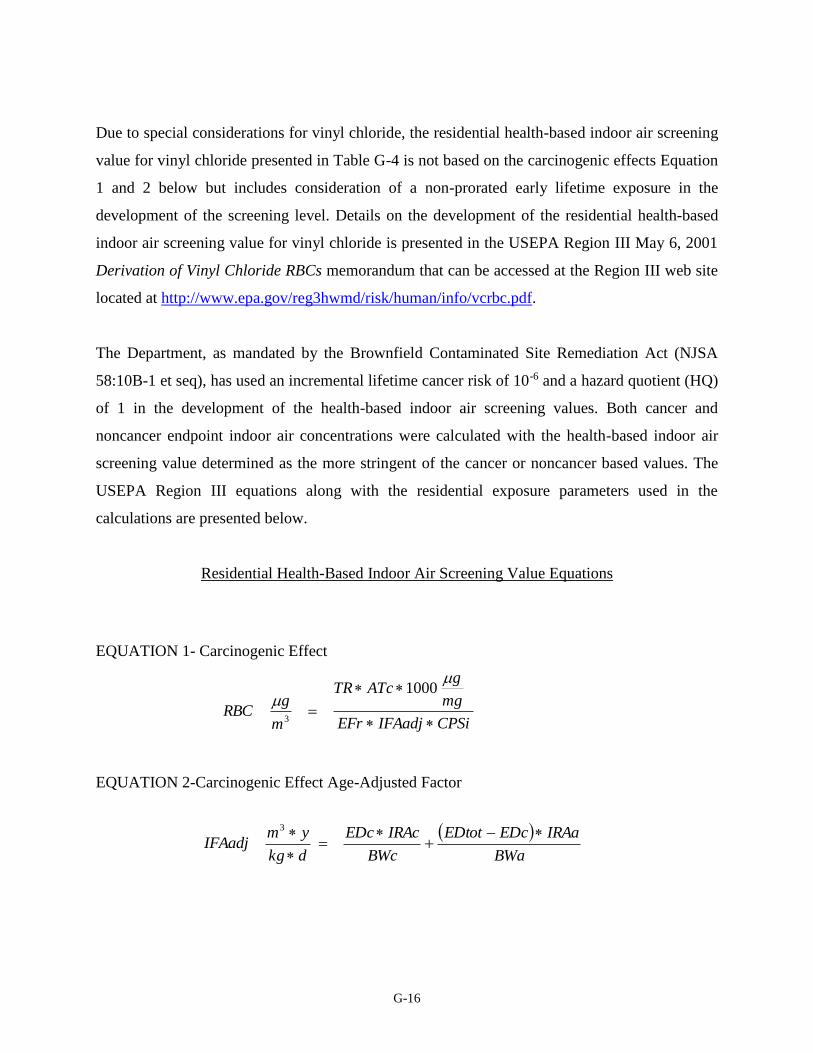
G-16
Due to special considerations for vinyl chloride, the residential health-based indoor air screening
value for vinyl chloride presented in Table G-4 is not based on the carcinogenic effects Equation
1 and 2 below but includes consideration of a non-prorated early lifetime exposure in the
development of the screening level. Details on the development of the residential health-based
indoor air screening value for vinyl chloride is presented in the USEPA Region III May 6, 2001
Derivation of Vinyl Chloride RBCs memorandum that can be accessed at the Region III web site
located at http://www.epa.gov/reg3hwmd/risk/human/info/vcrbc.pdf.
The Department, as mandated by the Brownfield Contaminated Site Remediation Act (NJSA
58:10B-1 et seq), has used an incremental lifetime cancer risk of 10-6 and a hazard quotient (HQ)
of 1 in the development of the health-based indoor air screening values. Both cancer and
noncancer endpoint indoor air concentrations were calculated with the health-based indoor air
screening value determined as the more stringent of the cancer or noncancer based values. The
USEPA Region III equations along with the residential exposure parameters used in the
calculations are presented below.
Residential Health-Based Indoor Air Screening Value Equations
EQUATION 1- Carcinogenic Effect
EQUATION 2-Carcinogenic Effect Age-Adjusted Factor
CPSiIFAadjEFr
mg
gATcTR
m
gRBC
1000
3
BWa
IRAaEDcEDtot
BWc
IRAcEDc
dkg
ymIFAadj
3
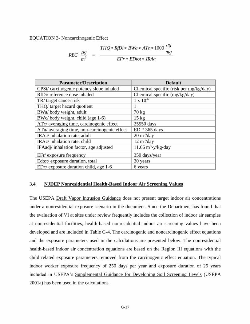
G-17
EQUATION 3- Noncarcinogenic Effect
Parameter/Description Default
CPSi/ carcinogenic potency slope inhaled Chemical specific (risk per mg/kg/day)
RfDi/ reference dose inhaled Chemical specific (mg/kg/day)
TR/ target cancer risk 1 x 10⁻⁶
THQ/ target hazard quotient 1
BWa/ body weight, adult 70 kg
BWc/ body weight, child (age 1-6) 15 kg
ATc/ averaging time, carcinogenic effect 25550 days
ATn/ averaging time, non-carcinogenic effect ED * 365 days
IRAa/ inhalation rate, adult 20 m3/day
IRAc/ inhalation rate, child 12 m3/day
IFAadj/ inhalation factor, age adjusted 11.66 m3-y/kg-day
EFr/ exposure frequency 350 days/year
Edtot/ exposure duration, total 30 years
EDc/ exposure duration child, age 1-6 6 years
3.4 NJDEP Nonresidential Health-Based Indoor Air Screening Values
The USEPA Draft Vapor Intrusion Guidance does not present target indoor air concentrations
under a nonresidential exposure scenario in the document. Since the Department has found that
the evaluation of VI at sites under review frequently includes the collection of indoor air samples
at nonresidential facilities, health-based nonresidential indoor air screening values have been
developed and are included in Table G-4. The carcinogenic and noncarcinogenic effect equations
and the exposure parameters used in the calculations are presented below. The nonresidential
health-based indoor air concentration equations are based on the Region III equations with the
child related exposure parameters removed from the carcinogenic effect equation. The typical
indoor worker exposure frequency of 250 days per year and exposure duration of 25 years
included in USEPA’s Supplemental Guidance for Developing Soil Screening Levels (USEPA
2001a) has been used in the calculations.
IRAaEDtotEFr
mg
gATnBWaRfDiTHQ
m
gRBC
1000
3

G-18
The nonresidential health-based screening values are appropriate for the typical commercial/
industrial indoor use of a site and are based on the adult worker as the most sensitive receptor.
Equations 4 and 5 used in the development of the nonresidential IASL are presented below.
Nonresidential Health-Based Indoor Air Screening Value Equations
EQUATION 4-Carcinogenic Effect
EQUATION 5-Noncarcinogenic Effect
PARAMETER/DESCRIPTION DEFAULT
CPSi/ carcinogenic potency slope, inhaled Chemical specific (risk per mg/kg/day)
RfDi/ reference dose, inhaled Chemical specific (mg/kg/day)
TR/ target cancer risk 1 x 10⁻⁶
THQ/ target hazard quotient 1
BWa/ body weight, adult 70 kg
ATc/ averaging time, carcinogenic effect 25550 days
ATn/ averaging time, non-carcinogenic effect ED * 365 days
IRAa/ inhalation rate, adult 20 m3/day
EFo/ exposure frequency, occupational 250 days/year
EDo/ exposure duration, occupational 25 years
3.5 Chemical Toxicity Factors
The Department has adopted the latest USEPA Region III RBC Table toxicity factors in the
generation of the screening levels (USEPA 2005). Table G-5 lists toxicity factors and sources of
the toxicity factors used in the calculations. As noted above, Region III converts the RfC/URF
values to dose based RfDi and CPSi values. Equations 6 and 7 used to convert the RfC and URF
CPSiIRAaEDoEFo
mg
gBWaATcTR
m
gRBC
1000
3
IRAaEDoEFo
mg
gATnBWaRfDiTHQ
m
gRBC
1000
3
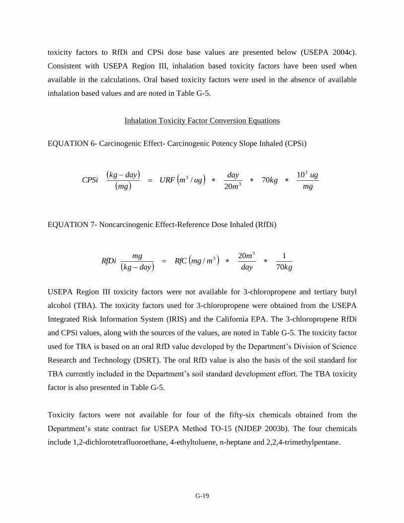
G-19
toxicity factors to RfDi and CPSi dose base values are presented below (USEPA 2004c).
Consistent with USEPA Region III, inhalation based toxicity factors have been used when
available in the calculations. Oral based toxicity factors were used in the absence of available
inhalation based values and are noted in Table G-5.
Inhalation Toxicity Factor Conversion Equations
EQUATION 6- Carcinogenic Effect- Carcinogenic Potency Slope Inhaled (CPSi)
EQUATION 7- Noncarcinogenic Effect-Reference Dose Inhaled (RfDi)
USEPA Region III toxicity factors were not available for 3-chloropropene and tertiary butyl
alcohol (TBA). The toxicity factors used for 3-chloropropene were obtained from the USEPA
Integrated Risk Information System (IRIS) and the California EPA. The 3-chloropropene RfDi
and CPSi values, along with the sources of the values, are noted in Table G-5. The toxicity factor
used for TBA is based on an oral RfD value developed by the Department’s Division of Science
Research and Technology (DSRT). The oral RfD value is also the basis of the soil standard for
TBA currently included in the Department’s soil standard development effort. The TBA toxicity
factor is also presented in Table G-5.
Toxicity factors were not available for four of the fifty-six chemicals obtained from the
Department’s state contract for USEPA Method TO-15 (NJDEP 2003b). The four chemicals
include 1,2-dichlorotetrafluoroethane, 4-ethyltoluene, n-heptane and 2,2,4-trimethylpentane.
mg
ugkg
m
dayugmURF
mg
daykgCPSi
3
3
3 1070
20/
kgday
mmmgRfC
daykg
mgRfDi
70
120/
33
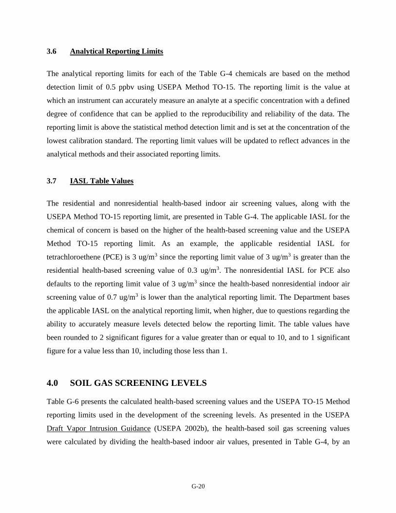
G-20
3.6 Analytical Reporting Limits
The analytical reporting limits for each of the Table G-4 chemicals are based on the method
detection limit of 0.5 ppbv using USEPA Method TO-15. The reporting limit is the value at
which an instrument can accurately measure an analyte at a specific concentration with a defined
degree of confidence that can be applied to the reproducibility and reliability of the data. The
reporting limit is above the statistical method detection limit and is set at the concentration of the
lowest calibration standard. The reporting limit values will be updated to reflect advances in the
analytical methods and their associated reporting limits.
3.7 IASL Table Values
The residential and nonresidential health-based indoor air screening values, along with the
USEPA Method TO-15 reporting limit, are presented in Table G-4. The applicable IASL for the
chemical of concern is based on the higher of the health-based screening value and the USEPA
Method TO-15 reporting limit. As an example, the applicable residential IASL for
tetrachloroethene (PCE) is 3 ug/m3 since the reporting limit value of 3 ug/m3 is greater than the
residential health-based screening value of 0.3 ug/m3. The nonresidential IASL for PCE also
defaults to the reporting limit value of 3 ug/m3 since the health-based nonresidential indoor air
screening value of 0.7 ug/m3 is lower than the analytical reporting limit. The Department bases
the applicable IASL on the analytical reporting limit, when higher, due to questions regarding the
ability to accurately measure levels detected below the reporting limit. The table values have
been rounded to 2 significant figures for a value greater than or equal to 10, and to 1 significant
figure for a value less than 10, including those less than 1.
4.0 SOIL GAS SCREENING LEVELS
Table G-6 presents the calculated health-based screening values and the USEPA TO-15 Method
reporting limits used in the development of the screening levels. As presented in the USEPA
Draft Vapor Intrusion Guidance (USEPA 2002b), the health-based soil gas screening values
were calculated by dividing the health-based indoor air values, presented in Table G-4, by an
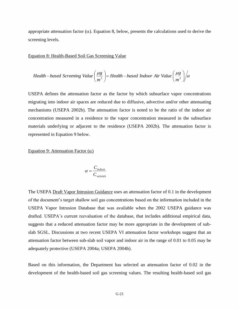
G-21
appropriate attenuation factor (). Equation 8, below, presents the calculations used to derive the
screening levels.
Equation 8: Health-Based Soil Gas Screening Value
USEPA defines the attenuation factor as the factor by which subsurface vapor concentrations
migrating into indoor air spaces are reduced due to diffusive, advective and/or other attenuating
mechanisms (USEPA 2002b). The attenuation factor is noted to be the ratio of the indoor air
concentration measured in a residence to the vapor concentration measured in the subsurface
materials underlying or adjacent to the residence (USEPA 2002b). The attenuation factor is
represented in Equation 9 below.
Equation 9: Attenuation Factor ()
subslab
indoor
C
C
The USEPA Draft Vapor Intrusion Guidance uses an attenuation factor of 0.1 in the development
of the document’s target shallow soil gas concentrations based on the information included in the
USEPA Vapor Intrusion Database that was available when the 2002 USEPA guidance was
drafted. USEPA’s current reevaluation of the database, that includes additional empirical data,
suggests that a reduced attenuation factor may be more appropriate in the development of sub-
slab SGSL. Discussions at two recent USEPA VI attenuation factor workshops suggest that an
attenuation factor between sub-slab soil vapor and indoor air in the range of 0.01 to 0.05 may be
adequately protective (USEPA 2004a; USEPA 2004b).
Based on this information, the Department has selected an attenuation factor of 0.02 in the
development of the health-based soil gas screening values. The resulting health-based soil gas
33 m
gValueAirIndoorbasedHealth
m
gValueScreeningbasedHealth
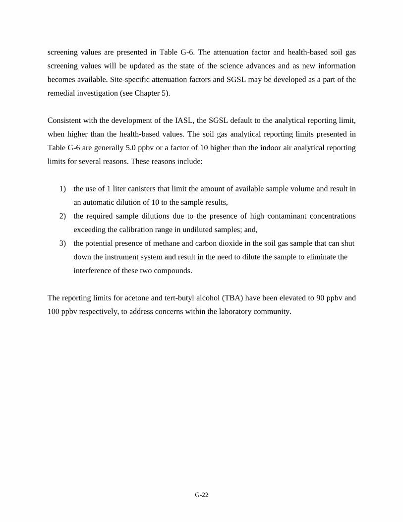
G-22
screening values are presented in Table G-6. The attenuation factor and health-based soil gas
screening values will be updated as the state of the science advances and as new information
becomes available. Site-specific attenuation factors and SGSL may be developed as a part of the
remedial investigation (see Chapter 5).
Consistent with the development of the IASL, the SGSL default to the analytical reporting limit,
when higher than the health-based values. The soil gas analytical reporting limits presented in
Table G-6 are generally 5.0 ppbv or a factor of 10 higher than the indoor air analytical reporting
limits for several reasons. These reasons include:
1) the use of 1 liter canisters that limit the amount of available sample volume and result in
an automatic dilution of 10 to the sample results,
2) the required sample dilutions due to the presence of high contaminant concentrations
exceeding the calibration range in undiluted samples; and,
3) the potential presence of methane and carbon dioxide in the soil gas sample that can shut
down the instrument system and result in the need to dilute the sample to eliminate the
interference of these two compounds.
The reporting limits for acetone and tert-butyl alcohol (TBA) have been elevated to 90 ppbv and
100 ppbv respectively, to address concerns within the laboratory community.
APPENDIX H
Common Household Sources of
Background IA Contamination
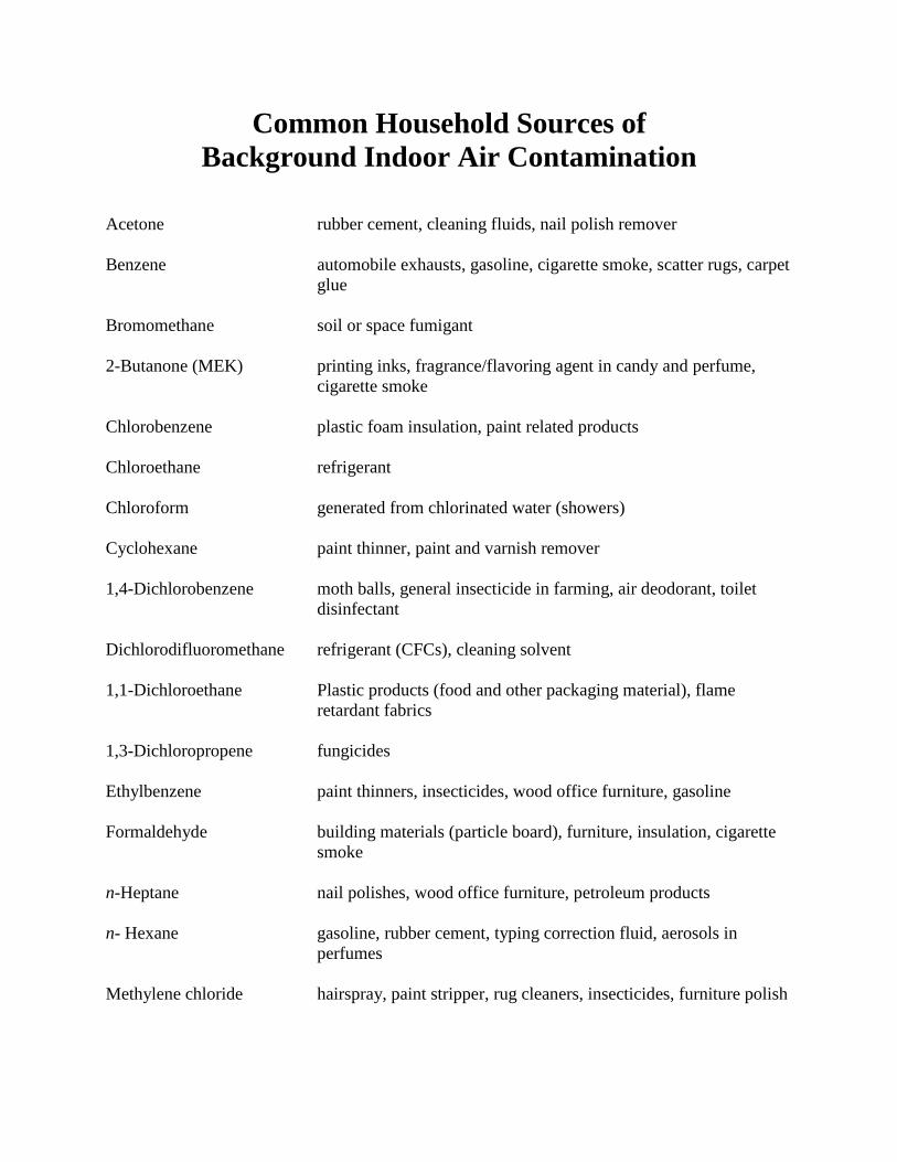
Common Household Sources of
Background Indoor Air Contamination
Acetone rubber cement, cleaning fluids, nail polish remover
Benzene automobile exhausts, gasoline, cigarette smoke, scatter rugs, carpet
glue
Bromomethane soil or space fumigant
2-Butanone (MEK) printing inks, fragrance/flavoring agent in candy and perfume,
cigarette smoke
Chlorobenzene plastic foam insulation, paint related products
Chloroethane refrigerant
Chloroform generated from chlorinated water (showers)
Cyclohexane paint thinner, paint and varnish remover
1,4-Dichlorobenzene moth balls, general insecticide in farming, air deodorant, toilet
disinfectant
Dichlorodifluoromethane refrigerant (CFCs), cleaning solvent
1,1-Dichloroethane Plastic products (food and other packaging material), flame
retardant fabrics
1,3-Dichloropropene fungicides
Ethylbenzene paint thinners, insecticides, wood office furniture, gasoline
Formaldehyde building materials (particle board), furniture, insulation, cigarette
smoke
n-Heptane nail polishes, wood office furniture, petroleum products
n- Hexane gasoline, rubber cement, typing correction fluid, aerosols in
perfumes
Methylene chloride hairspray, paint stripper, rug cleaners, insecticides, furniture polish

Methyl isobutyl ketone paints, varnishes, dry cleaning preparations, naturally found in
oranges, grapes, and vinegar
Methyl tert butyl ether gasoline (oxygenating agent)
Styrene cigarette smoke, automobile exhaust, fiberglass, rubber and epoxy
adhesives, occurs naturally in various fruits, vegetables, nuts, and
meats
1,1,2,2-Tetrachloroethane solvent, paint and rust removers, varnishes, lacquers
Tetrachloroethene (PCE) dry cleaning, metal degreasing, adhesives and glues, insecticide,
rug cleaner
Toluene gasoline, automobile exhaust, polishes, nail polish, paint thinner,
cigarette smoke
1,1,1-Trichloroethane spot cleaners, glues, insecticides, drain cleaners, shoe polish
Trichloroethene (TCE) scented candles, automotive cleaning and degreasing products
Xylenes, total water sealer, gasoline, automobile exhaust, markers, floor polish,
cigarette smoke
APPENDIX I
Quality Assurance Requirements

I-1
Quality Assurance Requirements
for USEPA Methods TO-15 and TO-17
The majority of the air sampling conducted in New Jersey for the investigation of the vapor
intrusion (VI) pathway is for volatile compounds. Thus, the focus of this section is on USEPA
Method TO-15 and USEPA Method TO-17.
USEPA Method TO-15 uses specially prepared leak free stainless steel canisters (canisters) for
the collection of air samples in the field (USEPA 1999). The samples are collected using the
subatmospheric pressure technique. The sample from the canister is directed through a cryogenic
concentrator on to a multisorbent trap and then on to a cryogenic focusing unit designed to
reduce the water content of the sample prior to introduction in the gas chromatogram/mass
spectrometer instrument system.
USEPA Method TO-17 uses sorbent tubes for the collection of air samples in the field. The tubes
are thermally desorbed into a gas chromatogram/mass spectrometer instrument system. The
method requires specific collection procedures and states that after desorption on to the column
the samples are to be analyzed in accordance with USEPA Method TO-15.
Both of the methods were published or updated in January 1999 and instrument technology has
advanced significantly since that time. There are sections in this guidance that reflect technology
advances that are not specified in the method.
NJDEP is adding requirements and clarifications to the methods based on the previous sampling
events carried out by NJDEP personnel.
I. CERTIFICATION REQUIREMENTS
All laboratories analyzing samples for submittal to the NJDEP must hold all the required NJDEP
Environmental Laboratory Certifications. NJDEP offers certification for USEPA Methods TO-15
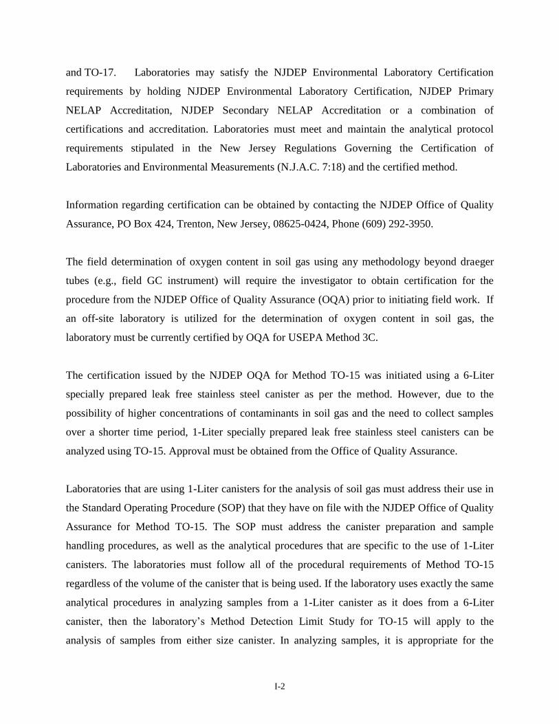
I-2
and TO-17. Laboratories may satisfy the NJDEP Environmental Laboratory Certification
requirements by holding NJDEP Environmental Laboratory Certification, NJDEP Primary
NELAP Accreditation, NJDEP Secondary NELAP Accreditation or a combination of
certifications and accreditation. Laboratories must meet and maintain the analytical protocol
requirements stipulated in the New Jersey Regulations Governing the Certification of
Laboratories and Environmental Measurements (N.J.A.C. 7:18) and the certified method.
Information regarding certification can be obtained by contacting the NJDEP Office of Quality
Assurance, PO Box 424, Trenton, New Jersey, 08625-0424, Phone (609) 292-3950.
The field determination of oxygen content in soil gas using any methodology beyond draeger
tubes (e.g., field GC instrument) will require the investigator to obtain certification for the
procedure from the NJDEP Office of Quality Assurance (OQA) prior to initiating field work. If
an off-site laboratory is utilized for the determination of oxygen content in soil gas, the
laboratory must be currently certified by OQA for USEPA Method 3C.
The certification issued by the NJDEP OQA for Method TO-15 was initiated using a 6-Liter
specially prepared leak free stainless steel canister as per the method. However, due to the
possibility of higher concentrations of contaminants in soil gas and the need to collect samples
over a shorter time period, 1-Liter specially prepared leak free stainless steel canisters can be
analyzed using TO-15. Approval must be obtained from the Office of Quality Assurance.
Laboratories that are using 1-Liter canisters for the analysis of soil gas must address their use in
the Standard Operating Procedure (SOP) that they have on file with the NJDEP Office of Quality
Assurance for Method TO-15. The SOP must address the canister preparation and sample
handling procedures, as well as the analytical procedures that are specific to the use of 1-Liter
canisters. The laboratories must follow all of the procedural requirements of Method TO-15
regardless of the volume of the canister that is being used. If the laboratory uses exactly the same
analytical procedures in analyzing samples from a 1-Liter canister as it does from a 6-Liter
canister, then the laboratory’s Method Detection Limit Study for TO-15 will apply to the
analysis of samples from either size canister. In analyzing samples, it is appropriate for the
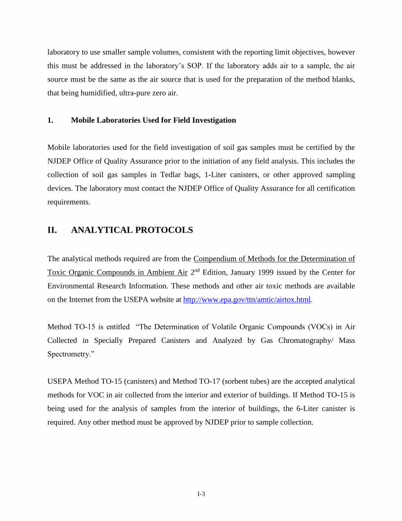
I-3
laboratory to use smaller sample volumes, consistent with the reporting limit objectives, however
this must be addressed in the laboratory’s SOP. If the laboratory adds air to a sample, the air
source must be the same as the air source that is used for the preparation of the method blanks,
that being humidified, ultra-pure zero air.
1. Mobile Laboratories Used for Field Investigation
Mobile laboratories used for the field investigation of soil gas samples must be certified by the
NJDEP Office of Quality Assurance prior to the initiation of any field analysis. This includes the
collection of soil gas samples in Tedlar bags, 1-Liter canisters, or other approved sampling
devices. The laboratory must contact the NJDEP Office of Quality Assurance for all certification
requirements.
II. ANALYTICAL PROTOCOLS
The analytical methods required are from the Compendium of Methods for the Determination of
Toxic Organic Compounds in Ambient Air 2nd Edition, January 1999 issued by the Center for
Environmental Research Information. These methods and other air toxic methods are available
on the Internet from the USEPA website at http://www.epa.gov/ttn/amtic/airtox.html.
Method TO-15 is entitled “The Determination of Volatile Organic Compounds (VOCs) in Air
Collected in Specially Prepared Canisters and Analyzed by Gas Chromatography/ Mass
Spectrometry.”
USEPA Method TO-15 (canisters) and Method TO-17 (sorbent tubes) are the accepted analytical
methods for VOC in air collected from the interior and exterior of buildings. If Method TO-15 is
being used for the analysis of samples from the interior of buildings, the 6-Liter canister is
required. Any other method must be approved by NJDEP prior to sample collection.

I-4
USEPA Method TO-15 can be used for soil gas analysis. However, the minimum canister size
that can be used is the 1-Liter canister. Method TO-17 is not appropriate for the collection of soil
gas samples.
Method TO-17 is entitled “Determination of Volatile Organic Compounds in Ambient Air Using
Active Sampling Onto Sorbent Tubes.”
USEPA Method TO-17 uses sorbent tubes as the method of sample collection. The method
requires specific collection procedures that must be followed. Additionally, the type and
frequency of the laboratory and field blanks type are mandated as per section 10.7.1 of the
method. After the tubes are desorbed on to the trap, Method TO-17 requires that USEPA Method
TO-15 be followed for the analysis of the samples.
Laboratories must meet and maintain the analytical protocol requirements stipulated in the New
Jersey Regulations Governing the Certification of Laboratories and Environmental
Measurements (N.J.A.C. 7:18) and USEPA Method TO-15. In addition, the laboratory must meet
all QA/QC requirements as specified in N.J.A.C. 7:18-5-5 and Methods TO-15 and TO-17.
III. LOW LEVEL ANALYSIS AND REPORTING
NJDEP currently only accepts analytical data from laboratories for Method TO-15 with the lowest
reporting limit of 0.2 ppbv. NJDEP is the process of standardizing requirements for the reporting
of analytical data below 0.2 ppbv, which will be considered low level analysis. This information
will be provided at a later date and will address both GC/MS Scan and GC/MS SIM requirements.
IV. REQUIREMENTS FOR BOTH METHODS
In accordance with the requirements of Method TO-17 Section 8.2 “Apparatus”, thermal
desorption of the tubes on to the trap is required. Following the desorption procedures, section
8.2.5 “GC/MS Analytical Components” states that the requirements of Method TO-15 are to be
I-5
followed. Therefore, the following sections dealing with any analytical or quality assurance
requirements pertain to both Method TO-15 and TO-17.
1. Gas Chromatography/Mass Spectrometry Tuning
The laboratory shall comply with all the GC/MS tuning requirements set forth in the instrument
operator's manual, USEPA Method TO-15, and the approved Laboratory Standard Operating
Procedure. Post acquisition manipulation of the ion abundances using computer software to
achieve tuning criteria is unacceptable. Any sample analyzed in conjunction with a failed tune
performance check requires a reanalysis. The laboratory shall comply with the requirements of
N.J.A.C. 7:18-5.2(a) 8 through 5.2(a) 13.
2. General Instrumentation Requirements
The laboratory shall meet and maintain the minimum standards for laboratory instrumentation set
forth in the “Regulations Governing the Certification Laboratories and Environmental
Measurements.” General instrument requirements are specified within these regulations at
N.J.A.C. 7:18-3.2 through 7:18-3.3 and N.J.A.C. 7:18-5.2(a)1 through 7:18-5.2(a)18. In addition,
the equipment requirements specified in the analytical method shall be met and maintained.
The laboratory shall maintain a bound paginated laboratory notebook with the analyst’s and
supervisor’s signature for archival storage of all data, except computerized data. The analyst and
the supervisor must sign any computerized printout or chromatogram not maintained in a
notebook on the first and last pages.
3. GC/MS Instrument Performance Tune Check Standard Requirements
The GC/MS Instrument Performance Tune Check Standard must contain BFB and cannot be
combined with any calibration standard to create an injection consisting of a calibration standard
and the tune solution. The BFB Tune Check Solution must be the first injection in any 24-hour
sequence. The BFB tune must meet the requirements of Table 3 Required BFB Key Ions and Ion
I-6
Abundance Criteria of the Method TO-15 and Method Sections 10.4.3 and 10.4.4 to be considered
acceptable.
4. Mass Spectral Library Requirements for GC/MS Analysis
The laboratory must maintain a gas chromatograph/mass spectrometer equipped with a
computerized MS library search system capable of providing reverse searching for targeted
analytes and forward searching for non-targeted analytes. The laboratory shall use the MOST
recent NIST/EPA/MSDC (May 1992 release or later), or the most recent Wiley (May 1991
release or later) mass spectral library for searches of targeted analytes. The system shall also be
capable of removing background signals from the suspect chemical pollutant spectrum
(background subtraction capability). The laboratory must also comply with N.J.A.C. 7:18-5.2(a)9
and N.J.A.C. 7:18-5.2(a)13)(iii).
The laboratory will operate the GC/MS in the SCAN mode unless the NJDEP approved VI
investigation workplan permits the samples to analyzed in the SIM Mode.
5. Electronic Media for Storage of Data
The laboratory shall store all raw data and processed electronic analytical data in the appropriate
instrument manufacturer’s format, uncompressed and with no security codes. The electronically
stored data shall include all data needed to completely reconstruct a hard copy and electronic
deliverable. The electronic data files shall include, but are not limited to, blanks, spikes, tunes,
calibrations, quality control samples, proficiency testing samples, and check samples. The
electronic data files shall also include all laboratory generated spectral libraries and quantitation
reports as well as the associated raw data files if those files contain data or instrument parameters
related to analytical results. The electronic data files must be sent to the NJDEP Office of
Quality Assurance within ten (10) days following a request for the files.
The laboratory must retain all raw and processed electronic data files for ten (10) years. The
laboratory shall comply with N.J.A.C. 7:18-5-6(a).
I-7
6. Qualitative Identification of Targeted Compounds by GC/MS
The compounds listed as required for Method TO-15 on the Master QA Form for Air shall be
identified by an analyst competent in the interpretation of mass spectra by comparison of the
sample mass spectrum to the mass spectrum of a standard to the suspected compound. The Method
TO-17 compounds must also meet this criterion, however, the compounds reported will be based
on the sorbent material used. Two criteria must be satisfied to verify the identifications: (1) elution
of the sample component at the same GC relative retention time as the standard component, and (2)
correspondence of the sample component and standard component mass spectra.
If an investigator (i.e., person(s) responsible for evaluating the VI pathway) wants to use Method
TO-17, they must follow the same requirements as those for Method TO-15, and as stated above
and below. A Method TO-17 Master QA Form has been developed for the volatile organic
compounds (USEPA Method TO-17 for Ambient Air: NJDEP Regulatory Reporting Format) and
found on the NJDEP Vapor Intrusion website. Each compound under analysis must be reported on
this form. This form can be modified for the reporting of compounds not listed on the form by
changing the compound name, CAS number, and molecular weight. The embedded calculation
will be operative.
For establishing correspondence of the GC relative retention time (RRT) the sample component
RRT must compare within + 0.06 RRT units of the RRT of the standard component. For reference,
the standard must be acquired in the same 24-hour time period as the sample. If samples are
analyzed within the same 24-hour time period as the initial calibration standard, use the RRT
values from the 10 ppbv standard (or the middle standard of the initial calibration). If co-elution of
interfering compounds prohibits accurate assignment for the sample component RRT from the total
ion chromatogram, the RRT should be assigned by using extracted ion current profiles for ions
used to obtain reference RRTs.
For comparison of standard and sample component mass spectrum, mass spectra obtained on the
laboratory’s GC/MS are required. Once obtained, these standard spectra may be used for
I-8
identification purposes only if the laboratory’s GC/MS meets the daily instrument performance
requirements for BFB. These standard spectra may be obtained from the run used to obtain
reference RRT.
All ions present in the standard mass spectra at a relative intensity greater than 10 percent (most
abundant ion in the spectrum equals 100.0 percent) must be present in the sample spectrum.
The relative intensities of ions specified above must agree within +\-20 percent between the
standard and sample spectra.
Ions greater than 10 percent in the sample spectrum but not present in the standard spectrum must
be considered and accounted for by the analyst making the comparison. The verification process
should favor false positives. All compounds meeting the identification criteria must be reported
with their spectra.
Structural isomers that produce very similar mass spectra can be explicitly identified only if they
have sufficiently different GC retention times. Acceptable resolution is achieved if the height from
the baseline to the valley between two peaks is less than 25% of the average height of the two
peaks. Otherwise, structural isomers are identified as isomeric pairs.
If a compound cannot be verified by all the criteria above, but in the technical judgment of the
mass spectral interpretation specialist the identification is correct, then the laboratory shall report
that identification with comment and proceed with quantitation. NOTE: Non Target Compound
identification is not required for air analysis.
V. SPECIFIC METHOD TO-15 REQUIREMENTS
1. Method TO-15 Canister Requirements
6-Liter Canisters for Building Interiors and Soil Gas Sampling - For the sampling of building
interiors and soil gas, the investigator can use leak-free stainless steel 6-Liter pressure vessel
I-9
canisters. These canisters must be equipped with a laboratory preset regulator, pressure gauge,
critical orifice, stainless steel frit dust filter over the orifice, and specially prepared interior
surfaces. Canisters are shipped to the investigator at subatmospheric pressure approximating
negative 30 inches of mercury. Hard seat metal valves are required for the shutoff valves on the
canisters. Soft-seated valves are not acceptable.
Building interior sampling and the accompanying background sample usually occurs over an 8
hour or a 24 hour period. The laboratory will preset the flow rate of the regulator to the sampling
period requested by the investigator.
The maximum flow rate for the collection of soil gas using a canister is 200 milliliters per
minute. A 6-Liter canister with a preset flow rate of 200 milliliters per minute and a critical
orifice of 0.0060 inches, and not drawing against backpressure constraints, will fill in
approximately 30 minutes.
The backpressure is primarily a factor of the length of the tubing from the sampling point to the
canister, the interior diameter of the tubing, the construction of the sampling probe, and the soil
type. If the backpressure constraint is greater than the vacuum in the canister, sample collection
will not occur. When possible, the system backpressure should be evaluated prior to sampling.
1-Liter Canisters for Soil Gas - For the sampling of soil gas, the investigator can use leak-free
stainless steel 1-Liter pressure vessel canisters equipped with a critical orifice, a stainless steel
frit dust filter over the orifice, and specially prepared interior surfaces. The canisters are shipped
to the investigator at a subatmospheric pressure approximating negative 30 inches of mercury.
Hard seat metal valves are required for the shutoff valves on the canisters. Soft seated valves are
not acceptable.
Installation of flow regulators on 1-Liter canisters used for the collection of soil gas samples may
not be practical, or may actually hinder the collection of the samples. A major concern during the
collection of soil gas samples is the backpressure that may be caused by the sampling train used
in the field. Given the dimensions of some of the 1-Liter canister, it may not be possible to

I-10
secure a pressure gauge directly to the canister. It is important that the investigator
communicates their needs with the laboratory before the canisters and regulators are sent to the
field. The investigator may need to be provided with a specially fitted pressure gauge from the
laboratory with each set of canisters in order to provide for the vacuum checks before and after
sample collection.
A regulator with a preset flow rate that does not match the flow rate of the sampling train will
constrain sample collection, and for this reason the use of flow regulators is not recommended.
The use of a critical orifice to moderate the flow is recommended for this type of sampling. A 1-
Liter canister equipped with a 0.0060 inch critical orifice (provides a flow rate of 200 milliliters
per minute), and not drawing against backpressure constraints, will fill in approximately 5
minutes.
Design changes by the canister manufacturer now allow pressure gauges to be added as part of
the sampling train for the 1-Liter canisters. If the laboratory is able to supply pressure gauges in
line with the canister, the investigator will not have to obtain a separate pressure gauge from the
laboratory.
The investigator, at the completion of the estimated fill time, is required to assess the vacuum of
the 1-liter canisters to determine if they have adequate sample volume. If a vacuum gauge is not
attached directly to the regulator, the investigator will shut down the system, break the tubing
connection to install the laboratory provided pressure gauge to check the vacuum of the
canisters. Adequate sample volume has been achieved if the pressure gauge is under –5 inches of
Mercury. If the canister is not below –5 inches of Mercury, the investigator should reconnect the
canister and continue sample collection.
2. Canister Preparation
The laboratory shall prepare canisters for sample analysis in accordance with the procedures
specified in the SOP approved by the NJDEP Office of Quality Assurance during the
certification process and with the provisions of the method. The laboratory must record the
I-11
current and actual temperature and barometric (atmospheric) pressure of the room at the time the
canisters (with the regulators) are prepared for shipment. Regulators, while not recommended for
1-Liter canisters, are an option.
3. Limitations on the Number of Days Canisters can be out of the Laboratory
Both 6-Liter and 1-Liter canisters after evacuation to approximately –30 Inches of Mercury have
a finite time frame before the level of the pressure loss that occurs naturally will inhibit the use
of the canister in sample collection. Due to the lost of pressure that occurs naturally during the
storage of canisters, NJDEP is establishing a fifteen (15) calendar day time limit that canisters
can be out of the laboratory. The fifteen-day time limit begins with the shipment of the canisters
to the investigator. The canisters must be returned to the laboratory after 15 calendar days
whether they were used for sample collection or not.
4. Setting the Regulators
All 6-Liter canisters must be provided with sample collection regulators. Regulators are optional
for 1-Liter canisters. The regulators must be flexible enough to collect samples over a variety of
time frames. The maximum sampling time will be 24 hours for 6-Liter canisters and 4 hours for
1-Liter canisters. The investigator will direct the laboratory to preset the canister regulators to
specific sample collection times. It will be the laboratory's responsibility to preset the regulators
for the sample collection time frames specified and to clearly identify each canister's regulator
preset sample collection time. The laboratory must record the current and actual temperature and
barometric (atmospheric) pressure of the room at the time the canisters (with the regulators) are
prepared for shipment.
5. Temperature Requirements for Sample Shipment
This method doesn’t have any temperature requirements for shipment since stainless steel
canisters are used for sample collection.

I-12
6. Sample Delivery Group
A Sample Delivery Group (SDG) is a unit of no greater than twenty (20) canisters collected at a
particular site. The SDG assignment is made upon receipt of the samples at the laboratory’s
facility. If less than twenty (20) samples are submitted for a particular site, it is considered a
single SDG. If more than twenty samples are submitted from a particular site, then the laboratory
is required to split those samples into separate SDGs of 20 or less and analyze each SDG with
the appropriate number of QC samples.
A SDG is a group of 20 or fewer samples received over a period of up to seven (7) calendar
days. Data from all samples in a Sample Delivery Group are due concurrently.
Samples from the sampling event may be assigned to a SDG at the discretion of the laboratory.
Laboratory Control Samples and Laboratory Control Sample Duplicates are considered QC
samples and are not included in the sample count for a SDG.
The SDG assignment made by the laboratory is not related to the analytical sequence. The
sample delivery group assignment is strictly used to track the movement of the samples in the
laboratory, for defining the SDG and the production of the analytical data package.
7. Collection of Field Duplicates
NJDEP does not require the collection of Field Duplicates for Method TO-15. NJDEP has
instituted the use of Laboratory Control Samples instead.
8. Trip Blank Canisters
NJDEP does not require the collection of trip blank canisters for any Method TO-15 sampling
event. Trip blanks are defined as canisters that are prepared at the laboratory, shipped to
investigator and shipped back to the laboratory unopened.
I-13
9. Ambient Temperature and Pressure Determinations during Sample Collection
For a sampling event, there are two ways to attain this information. The first way to obtain
information is from the nearest weather reporting station. This information can be acquired
directly from the station or from information posted on the Internet. Two websites that may be
useful to the investigator are the National Oceanic and Atmospheric Administration, National
Weather Service website at http://www.weather.gov or Weather Underground at
http://www.wunderground.com/. The investigator can also bring portable instrumentation on site
to obtain the information real time. The investigator must specify how the ambient pressure and
temperature will be obtained in the workplan, including but not limited to the weather station
from which the information will be obtained or the make and model of the portable instrument
will be for the measurements. In the sampling report, the actual procedures used must be
specified.
For interior samples, the collection of the ambient temperature cannot be obtained from a
weather station or the Internet. This information must be obtained from portable instrumentation
brought on site by the investigator to obtain the information real time. This information is sample
location specific, because there can be temperature variations within a building. As part of the VI
investigation workplan, the investigator must specify how this information is to be collected and
the type of instrument that will be used in the interior of buildings. In the sampling report, the
actual procedures used must be specified.
10. NJDEP TO-15 Field Test Data Sheets
The NJDEP TO-15 Field Test Data Sheets (FTDS), as provided at the end of this appendix, must
be completed for each canister used in the sampling events. All information must be completed
on the FTDS for each canister, and for both the fixed laboratory and a mobile laboratory. The
FTDS will be initiated by the laboratory and will accompany the canisters to and from the field.
The laboratory will fill out Canister Serial Number at the top of the form in the General
Information Section and the Batch Certification Number or File Number (as applicable) and the
I-14
Date Shipped at the bottom section of the form in the Laboratory Information Section. The FTDS
will be included in the analytical data package prepared by the laboratory. The FTDS must be
located immediately behind the case narrative of the data package and prior to any sample data.
11. Pressure of Canisters
Laboratories must check and record the negative or subatmospheric pressure of all canisters prior
to shipping and upon return receipt. This negative pressure information must be recorded in a
laboratory notebook and reported in the Data Package. The use of “<” or “>“ from the standard
pressure of 30 inches is not acceptable; the actual numeric reading is required.
Recent advances in the concentrator units (for example, the Entech™ 7100A Concentrator)
allows laboratories to remove samples from canisters with a negative pressure of –10 inches of
mercury without having to add makeup air. There are older concentrators such as the NuTechs
that only can pull from canisters that are less than –5 inches of Mercury. It is acceptable to use
either the older type or the advanced concentrator units.
The laboratory cannot automatically add makeup air to every canister received. The amount of
air that is added to each canister cannot be a standard amount because the determination of the
amount of air that must be added is based on the pressure that is in the canister at the time it is
received at the laboratory. The amount of air added to any canister cannot cause the total amount
of air in the canister to exceed 6.5 Liters. Ideally, the total amount of air in a canister should not
exceed 6 Liters. Additionally, if the canister is received at the laboratory at a pressure that does
not require air to be added, the addition of makeup air is prohibited. The laboratory SOP must
clearly describe how the pressure of the canister is determined and exactly how the amount of
makeup air to be added to canisters is determined.
If a sample of air is received and the negative pressure in the canister is less than –10 (or-5
inches if an older concentrator is used) inches of mercury, the laboratory may proceed with the
analysis of the sample as specified in Method TO-15. (Note: It is understood that a sample
should never be received at zero negative pressure or a pressure equal to atmospheric pressure.
I-15
The laboratory should consult the investigator for guidance on analyzing the samples in these
situations.) The humidified ultra pure zero air that is added to a canister for pressure adjustment
must be from the same source as the method blank air.
Example: If a sample is received with a negative pressure of -5 inches of mercury, the laboratory
may proceed with any pressure adjustment as needed for analysis. If pressure adjustment is
required, the analyst must bring the canister pressure up to the method specified pressure using
humidified, ultra-pure zero air. This is the same air as used for the method blank. The procedures
to correct the negative pressure of the canister must be documented in the Case Narrative of the
Data Package. Additionally, when the canister pressure is adjusted, a table entitled Canister
Dilution Calculations must be provided in the Data Package. NJDEP Method TO-15 Ambient Air
Regulatory Data Report (found on the NJDEP Vapor Intrusion website) specifies the
documentation requirements for the table.
If the negative pressure in a sample is greater than -10 inches of mercury, then the laboratory
must contact the investigator immediately for permission to analyze the sample.
Example: If a sample is received with a negative pressure of -12 inches of mercury, the
laboratory must contact the investigator for permission to analyze the sample. Contact NJDEP
for guidance on whether this sample should even be analyzed due to the incomplete sample
collection.
12. Volume of Sample Used for Analysis
The undiluted volume of sample drawn from the canister for analysis will vary from laboratory
to laboratory based on the procedures established by the laboratory and by the instrumentation
employed. There are two acceptable procedures for sample dilution.
The first procedure is the use of smaller volumes of air drawn from the canister and injected on
the column. Certain mass flow controllers on the instruments allow smaller volumes to be drawn
from the canister, thus creating a dilution without the addition of makeup air.

I-16
The second procedure is to draw a known volume from the canister and injecting the volume into
another certified clean canister. A known volume of ultra pure humidified zero air is then added
to the second canister. The dilution factor is determined based on the initial volume of air and
the makeup air. A volume of air is then drawn from the second canister and injected onto the
instrument.
Both procedures must be documented on the instrument logbook page. If the second canister is
used, the clean canister certificate documentation must be provided.
13. Specific Requirements for Method Detection Limits, Clean Canister Certification
and Reporting Limits for 6-Liter Canisters used in Building Interiors
Method Detection Limits for 6-Liter Canisters for Building Interior Sampling - The laboratory
shall calculate all Method Detection Limits (MDLs) in accordance Method TO-15. Section 11.2
requires the use of the procedures stated in Appendix B of 40 CFR 136 for performing the MDL
study. There are specific criteria that the laboratory must meet regarding the MDL. The MDL is
a statistical determination based on the requirements of the Method. Method Detection Limit
Studies must be conducted yearly.
The MDL determination is the same concentration as used for the low calibration standard (for
example 0.5 ppbv) in the initial calibration.
The recommended spiking level for the MDL determination is the same concentration as used for
the low calibration standard (for example 0.5 ppbv) in the initial calibration.
Required MDL Levels - The maximum MDL reported for each target analyte must be less than
or equal to the clean canister certification specified in Method TO-15. The clean canister
certification level is established in Method TO-15, Section 8.4.1.6.
I-17
The maximum MDL for acetone (2-propanone) and tert-butyl alcohol have been elevated to
address various concerns within the laboratory community. The MDL for acetone is 1.0 ppbv
and for tert-butyl alcohol to 3.0 ppbv. Laboratories may use lower MDLs for these compounds.
The submittal requirements for the Method Detection Limit Study is located in Method TO-15
Regulatory Reporting Format found on the NJDEP Vapor Intrusion website. This information
must be reported in each Analytical Data Package generated for a sampling event.
Clean Canister Certification for 6-Liter Canisters for Building Interior Sampling - The laboratory
is required to follow the requirements of Method TO-15, Section 8.3 and their approved NJDEP-
OQA SOP regarding cleaning and certifying canisters.
The canisters must be batch cleaned and certified with all Method TO-15 target analytes <0.2
ppbv. The laboratory must document which canisters are associated with each batch certification.
The actual level to which the canisters are certified to must be provided on the reporting form for
the clean canister certification. If the canister used for batch certification exceeds these levels,
the entire batch must be recleaned and recertified.
The clean canister certification level for acetone (2-propanone) and tert-butyl alcohol has been
elevated to address various concerns within the laboratory community. The contamination levels
for these two compounds cannot exceed the new specified levels. The clean canister certification
for acetone is 3.0 ppbv, and for tert-butyl alcohol is 6.0 ppbv. Laboratories may use lower clean
canister certification levels for these compounds.
The GC/MS documentation for clean canister certification is to be included in the Data Package
(found on the NJDEP Vapor Intrusion website).
Reporting Limits 6-Liter Canisters for Building Interior Sampling - The reporting limit is the
value at which an instrument can accurately measure an analyte at a specific concentration with a
defined degree of confidence that can be applied to the reproducibility and reliability of the data.
I-18
This value is above the statistical method detection limit and is set at the concentration of the
lowest calibration standard.
The maximum Reporting Limit (RL) for each target analyte must be less than or equal to 0.5
ppbv as required by Method TO-15, Section 11.1.1.
The maximum RL for acetone (2-propanone) and tert-butyl alcohol has been elevated to address
various concerns within the laboratory community. The RL for acetone is 9.0 ppbv and that for
tert-butyl alcohol to10.0 ppbv. Laboratories can use lower RLs for these compounds.
14. Specific Requirements for Method Detection Limits, Clean Canister Certification
and Reporting Limits for 1 Liter and 6-Liter Canisters used for Soil Gas Sampling
Method Detection Limits for 1-Liter and 6-Liter Canisters for Soil Gas Sampling - The
laboratory shall calculate all Method Detection Limits (MDLs) in accordance Method TO-15.
Section 11.2 requires the use of the procedures stated in Appendix B of 40 CFR 136 for
performing the MDL study. There are specific criteria that the laboratory must meet regarding
the MDL. The MDL is a statistical determination based on the requirements of the Method. The
laboratory determines a level, above the statistical MDL, at which a defined degree of confidence
can be applied to the reproducibility and reliability of the data. This value is commonly referred
to as the Reporting Limit. Method Detection Limit Studies must be conducted yearly.
The MDL determination is the same concentration as used for the low calibration standard (for
example 0.5 ppbv) in the initial calibration.
The recommended spiking level for the MDL determination is the same concentration as used for
the low calibration standard (for example 0.5 ppbv) in the initial calibration.
Required MDL Levels - The maximum MDL reported for each target analyte must be less than
or equal to the clean canister certification specified in Method TO-15. The clean canister
certification level is established in Method TO-15, Section 8.4.1.6.
I-19
The maximum MDL for acetone (2-propanone) and tert-butyl alcohol have been elevated to
address to address various concerns within the laboratory community. The MDL for acetone is
1.0 ppbv and for tert-butyl alcohol to 3.0 ppbv. Laboratories may use lower MDLs for these
compounds.
The submittal requirements for the Method Detection Limit Study are located in Method TO-15
Regulatory Reporting Format (found on the NJDEP Vapor Intrusion website). This information
must be reported in each Analytical Data Package generated for a sampling event.
Clean Canister Certification for 1- liter and 6-Liter Canisters for Soil Gas Sampling - The
laboratory is required to follow the requirements of Method TO-15, Section 8.3 and their
approved NJDEP- OQA SOP regarding cleaning and certifying canisters.
The clean canister certification level for the 1-liter canisters and 6-Liter canisters used for soil
gas sampling must be down to 0.4 ppbv except for acetone and tert-butyl alcohol which have a
maximum clean canister certification level of 6.0 ppbv. The laboratory has the option of using a
lower reporting limit. The actual level to which the canisters are certified to must be provided for
on the reporting form for clean canister certification. If the canister used for the batch
certification exceeds these levels, the entire batch must be recleaned and recertified. The
laboratory must document which canisters are associated with each batch certification.
The GC/MS documentation for clean canister certification is to be included in the Data Package.
Soil Gas Reporting Limits - NJDEP has elevated the Reporting Limits for the Near Slab and Sub
Slab soil gas samples. The elevation of the Reporting Limits for this type of sampling is at the
option of the laboratory conducting the analysis. For all compounds except for acetone and tert-
butyl alcohol, the Reporting Limit has been increased from 0.5 ppbv to 5.0 ppbv. The Reporting
Limit for acetone has been increased from 9.0 ppbv to 90.0 ppbv and for tert-butyl alcohol from 10
ppbv to 100 ppbv. The laboratory has the option of using a lower reporting limit.
I-20
15. Water Content in Canisters
The investigator must be aware of the height of the water table when collecting soil gas samples.
The sample point must be above the capillary fringe of the water table to limit the amount of
water that is collected in the canisters. Additionally, interior building samples and the associated
background samples can also be affected by humidity. The analytical instrument manufacturers
are acutely aware of this problem. The limitation of the laboratory’s analytical system is caused
by the inability of the traps in the concentrator units to remove the water from the sample. If
there is too much water in the canister, the laboratory will be unable to analyze the sample. In
fact, the Entech Concentrator Model 7100 Manual states that 1.0 L of air at 70% RH and room
temperature contains 18 L of water. Therefore, if a 500 ml sample size from the canister is used
the system is designed to handle up to 9 L of water present in the injected volume. The
investigator should discuss the water content limitations with the laboratory analyzing the
samples.
16. Replicate Samples
The laboratory has the option to analyze a replicate sample from one of the canisters from the
sampling event. A replicate analysis defined as a second volume drawn from a canister that is
treated the same as the original sample in order to determine the precision of the method. The
frequency of the replicate cannot exceed one sample for every twenty samples submitted for a
particular sampling event. The laboratory cannot automatically add additional humidified zero
air to the canister that they have chosen of the replicate analysis prior to the analysis of the parent
sample and the replicate sample.
17. Tracer Compounds for Soil Gas
Tracer compounds are required to determine if the soil gas collection system is free of leaks.
NJDEP is recommending the use of two tracer compounds, isopropyl alcohol or n-butane. Prior to
the initiation of sampling, the investigator must contact the laboratory to determine which tracer
I-21
compound the laboratory is currently including in its calibration. Laboratories are not required to
provide tracer gas to the investigator. In most commercially prepared gas standard cylinders,
isopropyl alcohol is in the mixture, while n-butane may not be in the standard mixture. If the
investigator wants to use n-butane as the tracer compound, the laboratory will be required to obtain
commercially prepared gas standards that contain n-butane.
18. Holding Times
Samples collected in stainless steel canisters must be analyzed within thirty (30) calendar days of
sample collection.
19. Standards Preparations
The laboratory must use gaseous standards (not water standards) for any analysis conducted using
USEPA Method TO-15. The laboratory must purchase commercially prepared gaseous standards
from one of the standard suppliers. The laboratory must use standard mixtures of target gases in
high pressure cylinders certified traceable to a NIST Standard Reference Materials (SRM) or
NIST/USEPA approved Certified Reference Material (CRM). The use of water standards is
prohibited. The laboratory must certify in the case narrative of each data package that gaseous
standards have been used. The laboratory must specify their suppliers in the Standard Operating
Procedure submitted to the Office of Quality Assurance for certification. The use of laboratory
generated standards using static bottle dilution technique, permeation tubes, water standards or
dynamic dilution using neat liquids is not acceptable.
20. Second Source for Standards
All laboratories are required to use a gaseous standard purchased from a commercial gas
standard supplier for all Laboratory Control Samples. This does not preclude purchasing of other
standards from a second outside source. The second source must be a commercially prepared gas
standard purchased from a standard supplier. The Standards prepared by laboratory personnel
from neat standards do not meet the requirements of a gas standard second source. The standard
I-22
must contain all the compounds of interest. NJDEP recognizes the fact that currently there are a
limited number of gas standards suppliers in the country and purchasing gas standards from
different suppliers usually will involve the handling and storage of numerous gas cylinders. The
second source can be from a different supplier or from an independent lot (different from the lot
used for the calibration standards) certified from their current gas standard supplier. The
laboratory must document in their Standard Operating Procedures how they handle the second
source for standards and document it in the standards logbooks. The second source supplier and
which standard uses a second source must be listed in the case narrative.
21. Method Blanks
The laboratory is required to follow the requirements of Method TO-15 Section 10.7 regarding
method blanks. Any method blank that deviates from the preparation and technical acceptance
requirements specified in the method is not acceptable and will be rejected. Any analysis that is
related to a failed method blank will also be rejected.
22. Instrument Blanks
If the laboratory determines during the analytical sequence that an instrument blank needs to be
analyzed for any reason within an analytical sequence, the instrument is to meet the requirements
of Method TO-15 Section 10.7 to be acceptable. The samples must be labeled as an instrument
blank and the reason for analyzing the blank documented in the case narrative and the instrument
run log.
23. Laboratory Control Samples
The laboratory is required to analyze two Laboratory Control Samples (LCS) each time a method
blank is analyzed.
The LCS must be prepared in the same manner as the method blank (USEPA Method TO-15
Section 10.7) with the only difference being that the canister is spiked with all compounds at a
I-23
concentration of 10 ppbv or at the same concentration as the midpoint calibration standard. The
LCS is required to meet the same technical requirements as a method blank as provided for in
USEPA Method TO-15 Section 10.7.5.
The LCS recovery must be within 70-130 % of the spiked value for 90 % of the compounds for the
LCS to be considered acceptable. In addition, the LCS must be analyzed immediately after the
calibration standard and prior to the method blank analysis for each 24-hour window following the
daily calibration standard.
In a calibration sequence that is used to certify a canister as clean as per the method, only one LCS
sample is required to be analyzed in the sequence.
24. Internal Standards
During the course of sample analysis, the laboratory may determine that the internal standard area
response is outside the control limits as established by Method TO-15, Section 10.8.6. When this
occurs, the laboratory must comply with the corrective action procedures specified in the method
and reanalyze the sample as required. The laboratory must report data for both the initial analysis
and the reanalysis. The laboratory may not submit more than two sets of data. If upon reanalysis of
the sample after corrective action, the internal standard area responses are within the control limits
established by the method, the problem is determined to be within the control of the laboratory and
the laboratory will submit only the compliant analysis. If upon reanalysis of the samples, the
internal standard area responses are outside of the control limits established by the method, a
matrix effect is occurring. This matrix effect is outside the control of the laboratory. Therefore, the
laboratory will submit both analyses.
25. Analytical Sequence for Sample Analysis
Method TO-15 specifies the analytical sequence for the analysis of samples. The only addition to
this sequence is the analysis of the two (2) Laboratory Control Samples prior to the analysis of the
method blank and after the completion of the initial calibration sequence or daily calibration.
I-24
Method TO-15 Sections 10.4 -10.8 reference the analytical sequence required for the initial and
daily calibration requirements. The laboratory must meet both the method and guide requirements
for the initial and daily calibrations.
26. Dilutions Due to Calibration Range Exceedence
The laboratory in their NJDEP OQA approved Standard Operating Procedure (SOP) must
establish screening procedures and procedures specifying limitation’s analyte concentration
above the upper point of calibration that will require dilution analysis. If the laboratory has not
established these procedures, they must revise their SOP accordingly and submit the documents
to the NJDEP OQA for approval.
Unless screening results determine otherwise, the laboratory must analyze the sample as
undiluted. The criteria for determining when a dilution is required is when the peak response of
any target analyte in the sample exceeds the peak response in the highest standard in the initial
calibration. At that point, a new volume of air must be drawn from the canister, diluted and
reanalyzed.
When the screening results indicate that the peak response of a target analyte will exceed the
peak response in the highest standard in the initial calibration (as per the approved SOP), the
laboratory is not required to analyze the sample as undiluted. Instead, the laboratory will be
required to analyze the sample at a most concentrated dilution and one further dilution to
demonstrate the dilution level is correct.
In both procedures, the dilution factor must keep the concentration of the target analyte that
required dilution in the upper half of the initial calibration range.
If the laboratory must add air to the sample that is being diluted, the source must be humidified
ultra pure zero air. This source is the same air that is used for method and instrument blanks.

I-25
All dilutions must be documented in the case narrative of the analytical data package. For
samples that are initially analyzed as undiluted, and if a dilution is then required, the laboratory
must report data for both analytical runs. For samples that are initially analyzed as diluted, the
laboratory must report data from the most concentrated dilution and one further dilution.
Both sets of data must be submitted as individual sample results. Merging of the results on the
data summary page or in electronic format is not acceptable.
Tracer Gas Dilutions - The laboratory is not required to dilute samples that have peak response
of any tracer gas in a sample that exceeds the peak response in the highest standard in the initial
calibration. The presence of the tracer gas in the sample must be documented in the Case
Narrative of the analytical data package and the concentration reported on the data summary
sheet for each sample.
Isopropanol and Ethanol - Laboratories reporting ambient air data by Method TO-15 are not
required to dilute samples to bring the concentration for isopropanol and ethanol within the
calibration range of the instrument (see Section VII of this appendix for additional information).
The laboratory must report the sample concentrations for these two compounds in the case
narrative. The laboratory should not report the isopropanol and ethanol results on any sample
data summary forms within the data package, nor on any electronic data format submitted to the
state.
27. Pressure and Temperature Issues
In preparing the canisters for sample collection, the laboratory establishes the flow rate of the
regulators based on the barometric (atmospheric) pressure and temperature inside the laboratory.
The laboratory must record the actual temperature and barometric (atmospheric) pressure of the
room at the time the canisters (with the regulators) are prepared for shipment. Canister pressure
for shipment from the laboratory must be set at –30 inches of mercury. The required flow control
regulators will stop the sample collection at a preset level that will maintain the interiors of the
canisters at a subatmospheric pressure as required by the method.

I-26
Once in the field, depending on the sampling location, the temperature and atmospheric pressure
changes that will occur over the sample collection time can affect the rate of sample collection.
Air samples are considered composite samples since they are collected over a set period, and the
variations can be expected. Additionally, since the regulators that control the flow of the samples
into the canister are preset at the laboratory, the actual flow rate into the canisters in the field
may differ. Temperature changes during the time of collection can decrease or increase the rate
of airflow into the canister. It will not affect the amount of sample being collected unless the
temperature increase is sufficiently high enough to slow the rate of collection. Research on the
effects of temperature indicates that a sharp decrease in the temperature (from the temperature at
which the regulators are set in the laboratory) during the period of sample collection will
increase the flow rate into the canister, while an increase in temperature will slow the flow rate.
Therefore, it is important that the changes in atmospheric pressure and temperature throughout
the sampling period be recorded by the investigator on the FTDS. The laboratory must record the
temperature and pressure in the laboratory when they perform the pressure check of the canisters
after equilibration to laboratory conditions.
Concerns have been raised regarding canisters that have been received at the laboratory at lower
or higher residual pressures that expected. The flow controllers are preset at the laboratory based
on the pressure inside the laboratory. Additionally, the laboratory evacuates the canisters to –30
inches of mercury based on the pressure within the laboratory. Atmospheric pressure differs from
the laboratory location to sampling location. Pressure changes due to fluctuating weather
conditions are a major cause of the pressure changes associated with the canisters. These changes
are inherent with any type of air sampling.
Examples: If the atmospheric pressure in the field during sample collection is lower than the
atmospheric pressure when the canister is received at the laboratory, the canister pressure will be
more negative at the laboratory than the final pressure recorded in the field.
I-27
If the atmospheric pressure in the field during sample collection is higher than the atmospheric
pressure when the canister is received at the laboratory, the canister pressure will be more
positive at the laboratory than the final pressure recorded in the field.
The critical issue is that the canister valves must be closed properly by the investigator so the
hard seated metal valves are not stripped by over tightening, which will cause leakage into the
canisters. The investigator should consult with laboratory on the proper closing procedures for
each canister type.
This guide now recommends the collection of ambient temperature and pressure readings during
the collection of air samples. See the requirements of the method specific field test data sheets.
VI. Specific Method TO-17 Requirements
1. Sampling Issues
The investigator must be aware that sorbent tube sampling is more involved than just setting a
stainless steel canister up in an area and coming back to pick it up. Sorbent tube sampling
requires choosing the right sorbent material, pump and pump flow rate. In addition, Method TO-
17 stipulates the collection of tubes in parallel at different rates. The sampling plan submitted to
the department must address how the investigator intends to meet all the requirements in the
guide, as well as those noted in Method TO-17. The investigator is advised to be familiar with
the various sampling issues prior to initiating the sampling event.
For each sampling point, the investigator will be required to collect two sorbent tubes for each
sampling point in parallel. The sorbent material in each tube must be same material. If additional
tubes are required to collect analytical data for the different contaminants of concern, separate
sampling units must be set up to collect the air samples.
The investigator must be aware of various issues under Method TO-17 that affect the
establishment of pump flow rates, including safe sampling volumes, time weighted averaged

I-28
monitoring requirements, and detection limit requirements. The pump rate must be set so that the
final calculated reporting limit used by the laboratory shall be less than or equal to 0.5 ppbv.
Sampling Volume Constraints - Method TO-17 uses the direct method for determining the safe
sampling volume constraints (SSVs). The direct method states the safe sampling volume is
calculated by taking two-thirds of the breakthrough volume. The investigator must take into
account the direct method in setting the pump flow rate
Time Weighted Average Monitoring Requirements - There are only two sampling times allowed
for Method TO-17, eight (8) hour and twenty four (24) 24 hour. The investigator must adjust the
pump flow rate to ensure SSVs are not exceeded during the collection period.
Detection Limit Requirements - Within the constraints of safe sampling volumes and pump flow
rates limits, air volumes selected for trace level (ambient) air monitoring should be maximized.
However, in all instances, the investigator must be aware that the Reporting limits cannot exceed
0.5 ppbv for any compound when reported by the laboratory.
The distributed volume pairs procedure as described in Method TO-17 Sections 10.7.2 and 14.4
is used to ensure high quality data in all initial investigations and for routine monitoring. The use
of single tube sampling may be allowed only in instances where NJDEP has determined that
acceptable data have been routinely obtained through use of distributed volume pairs and the
ambient air is considered to be well characterized.
The minimum sample collection time for the sorbent tubes has been established by NJDEP as
eight (8) hours. A twenty-four (24) hour sample collection time is the preferred sampling time,
since it provides a longer time weighted average for exposure.
The sorbent tubes collected in parallel must be collected at different rates. The ratio between the
two rates must be maintained at a proportion of 1:4. The investigator can adjust the flow rate to
accommodate low safe sampling volumes by proportionally reducing both rates. However, the
I-29
lower flow rate result cannot result in a sample volume less than 300 mL total volume. The 300
mL sample gives adequate detection limits (<0.5ppb per analyte) using a full scan GC/MS.
The choice of TO-17 sampling apparatus is left to the investigator. However, the apparatus must
conform to USEPA Method TO-17 Section 6.3.1, which requires accommodations for two
sampling tubes with the capability of independent control for sampling rate at a settable value in
the range of 10 to 200 ml/min.
2. Ambient Pressure and Temperature Requirements during Sample Collection
Method TO-17 requires the collection of the ambient temperature and pressure during the sample
collection time in order to calculate the concentrations reported for each sample.
For a sampling event there are two ways to attain this information. The first way is to obtain the
information from the nearest weather reporting station. This information can be acquired directly
from the station or this information from the Internet. Two websites that may be useful to the
investigator are the National Oceanic and Atmospheric Administration, National Weather
Service website at http://www.weather.gov or Weather Underground at
http://www.wunderground.com/. The investigator can also bring portable instrumentation on site
to obtain the information real time. The investigator must specify how the ambient pressure and
temperature was obtained in the sampling plan, including but not limited to the weather station
from which the information will be obtained or the make and model of the portable instrument to
utilized. In the sampling report, the actual procedures used must be specified.
For interior samples, the collection of ambient temperature cannot be obtained from a weather
station or the Internet. This information must be obtained from portable instrumentation brought
on site by the investigator to obtain the information real time. This information is sample
location specific, because there can be temperature variations with a building. So as part of the
sampling plan that uses Sorbent tubes, the investigator must specify how this information is to be
collected and the type of instrument that will be used in the interior of buildings. In the sampling
report, the actual procedures used must be specified.
I-30
3. Field Test Data Sheets
The Field Test Data Sheets (FTDS), as provided on Page 17-37 of the Method TO-17 and
reproduced at the end of this appendix as part of the Method TO-17 Regulatory Reporting
Format, must be completed to record all the required information regarding the sampling event.
At the end of the sampling period and PRIOR to switching off the each pump, the investigator is
required to recheck all sampling flow rates and record this information on the FTDS.
The FTDS or a copy must accompany the tubes to the laboratory for inclusion with the analytical
data package and for the laboratory to properly report the data. The FTDS must be located
immediately behind the case narrative of the data package and prior to any sample data.
4. Method TO-17 Sorbent Tubes
The laboratory shall prepare sorbent tubes and the blank tubes in accordance with the procedures
specified in the SOP approved by the NJDEP Office of Quality Assurance during the
certification process and with the provisions of the method.
5. Temperature Requirements for Sample Shipment
The cartridges must be chilled after sample collection with artificial ice to <4o Centigrade and
stored in refrigeration at the laboratory at less than 4o Centigrade unless the samples are analyzed
on the same day they are collected. The samples must be stored in an organic solvent free
environment. For shipment to and from the field, small packages of activated charcoal/ silica gel
must accompany each shipment container of multiple tubes.
6. Temperature Indicators for Sample Shipment
The laboratory may include a temperature indicator bottle in every shipping container containing
sorbent tubes. The temperature indicator bottle shall contain an appropriate liquid for monitoring
I-31
the temperature of the shipment case and the samples on arrival at the laboratory. The laboratory
is to place the temperature indicator bottle in an appropriate position in the shipping container
with the sample bottles. On receipt, sample custody personnel shall determine the temperature of
the shipping container and contents as cited below:
Locate temperature indicator bottle, remove screw cap and insert a calibrated thermometer (-50
to 50o Centigrade). Permit the thermometer to equilibrate for 3 - 5 minutes. The Sample
Custodian must record the temperature on the appropriate chain of custody and other appropriate
documents.
As an alternative to using a thermometer, the laboratory may check the temperature of a sample
bottle by using an infrared thermometer. Use of an infrared thermometer must comply with
NJDEP’s laboratory certification code at N.J.A.C. 7:18-3-3(a) 5 specifically, the verification and
accuracy requirements set forth in N.J.A.C. 7:18-3-3(a) 5v. Infrared temperature measuring
devices must be verified quarterly and the data entered into a logbook signed by the analyst.
7. Sample Delivery Group
A Sample Delivery Group (SDG) is a unit of no greater than ten sorbent tube samples collected
at a particular site. The SDG assignment is made upon receipt of the samples at the laboratory’s
facility. If less than ten (10) samples are submitted for a particular site, it is considered a single
Sample Delivery Group. If more than ten samples are submitted from a particular site, then the
laboratory is required to split those samples into separate Sample Delivery Groups of 10 or less
and analyze each sample delivery with the appropriate number of QC samples for each group.
A SDG is a group of 10 or fewer samples received over a period of up to seven (7) calendar
days, excluding Sundays and government holidays. In addition, samples from the sampling event
may be assigned to Sample Delivery Groups at the discretion of the laboratory.
I-32
The SDG assignment made by the laboratory is not related to the analytical sequence. The
sample delivery group assignment is strictly used to track the movement of the samples in the
laboratory and the production of the analytical data package.
8. Method Detection Limits
The laboratory shall calculate all Method Detection Limits (MDLs) in accordance Method TO-
17, Section 14.2 that requires the procedures, as stated in Appendix B of 40 CFR 136. The
maximum MDL for each Method TO-17 target analyte must be less than or equal to 0.5ppb as
required by Method TO-17 Section 14.1. The data must be reported in ppb.
There are specific criteria that the laboratory must meet. The MDL is a statistical determination
based on the requirements of the Method. The laboratory establishes a level above the Statistical
MDL at which they determine, with a certain degree of confidence, the reproducibility and
reliability of the data. In such instances, the laboratory states this value as the Reporting Limit.
According to Method TO-17 Section 7.4, “Detection Limits and Maximum Quantifiable
Concentrations of Air Pollutants,” detection limits for atmospheric monitoring vary depending
on several key factors. These factors are:
• Minimum artifact levels
• GC detector selection
• Volume of air sampled
The volume of air sampled is in turn dependent upon a series of variables including SSVs, pump
flow rate limitations, and time weighted average monitoring time constraints.
Generally speaking, detection limits range from sub-part-per-trillion (sub-ppt) for halogenated
species, such as CCl4, and the freons using an electron capture detector (ECD) to sub-ppb for
volatile hydrocarbons in 1 Liter air samples using the GC/MS operated in the full SCAN mode.

I-33
Detection limits are greatly dependent upon the proper management of water for GC capillary
analysis of VOC in air using sorbent technology.
The submittal requirements for the Method Detection Limit Study are located in Method TO-17
Regulatory Reporting Format (found on the NJDEP Vapor Intrusion website). This information
must be reported in each Analytical Data Package generated for a sampling event.
9. Reporting Limits
The reporting limit for Method TO-17 is based upon the amount of air that is drawn through the
tube during sample collection. The investigator must provide the actual amount of air pulled
through the tube. The FTDS found on page 17-37 of the method and in the Method TO-17
Regulatory Reporting Format should be used to record all of the field information. The reporting
limit will vary from sample to sample based on the volume of air drawn through the tube. The
reporting limit for any compound may vary from sample to sample. However, the reporting limit
for any compound cannot exceed 0.5 ppb.
10. Holding Times
Cartridges must be analyzed within 30 calendar days, except for when limonene, carene, bis-
chloromethyl ether and labile sulfur or nitrogen containing volatiles are present. If these
compounds are expected to be present, the holding time is 7 calendar days from sample collection.
11. General Analytical Requirements
In accordance with the requirements of Method TO-17 Section 8.2 “Apparatus”, thermal
desorption of the tubes into the trap is required. Following the desorption procedures, section 8.2.5
“GC/MS Analytical Components” states that the requirements of Method TO-15 are to be
followed. Therefore, the laboratory must meet any analytical or quality assurance requirements
pertaining to Method TO-15 following desorption into the trap. The laboratory must meet all
QA/QC requirements as specified in N.J.A.C. 7:18-5-5 and Methods TO-15 and TO-17.

I-34
12. Standard Preparations
The laboratory is allowed to use both gas phase standards (Method Section 9.2) and liquid phase
standards (Method Section 9.3) for Method TO-17.
Gas Standard Requirements - The laboratory must use standard mixtures of target gases in high-
pressure cylinders certified traceable to a NIST Standard Reference Materials (SRM) or
NIST/EPA approved Certified Reference Material (CRM). The use of water standards is
prohibited. The laboratory must certify in the case narrative of each data package that gaseous
standards have been used. The laboratory must purchase gaseous standards from a standard
supplier. The laboratory must specify their suppliers in the Standard Operating Procedure
submitted to the Office of Quality Assurance for certification.
Liquid Standard Requirements - The laboratory must use liquid standards that are certified
traceable to a NIST Standard Reference Materials (SRM) or NIST/EPA approved Certified
Reference Material (CRM). The laboratory must certify in the case narrative of each data package
when liquid standards are used. The laboratory must purchase liquid standards from a standard
supplier. The laboratory must specify their suppliers in the Standard Operating Procedure
submitted to the Office of Quality Assurance for certification.
13. Laboratory Blanks
The laboratory is required to follow the requirements of Method TO-17 Sections 10.7.1.1 and
13.1.1 regarding the type and frequency of analysis of laboratory blanks. Laboratory blanks are
sorbent tubes with identical packing as the tubes used for sample collection and are from the same
batch. They are stored in the laboratory at <4o Centigrade in a cleaned, controlled condition during
the time the environmental samples are out being collected. In addition, the laboratory blanks are
analyzed at the same time as the environmental samples, one at the beginning and one at the end of
the sequence of runs. Laboratory blanks, as defined in Method TO-17, is equivalent to method
blanks, as utilized in Method TO-15.
I-35
14. Field Blanks - Method TO-17
Field blanks are required when samples are collected for Method TO-17 analysis. The investigator
and the laboratory are required to follow the requirements of Method Sections 10.7.1.2 and 13.1.1.
15. Laboratory Control Samples
The laboratory is required to analyze one laboratory control sample (LCS) each time a method
blank is analyzed. They are stored in the laboratory at <4o Centigrade in a cleaned, controlled
condition during the time the environmental samples are out being collected.
The LCS must be prepared in the same manner as the laboratory blank (Method Section 10.7) with
the only difference being the tube is spiked with all compounds at a concentration of 20 ngs. In
addition, the LCS recovery must be within 70-130 % of the spiked value for 90 % of the
compounds of the LCS to be considered acceptable.
The LCS must be analyzed immediately after the calibration standard and prior to the laboratory
blank analysis for each 24-hour window following the daily calibration standard.
16. Analytical Sequence for Sample Analysis
Once the GC/MS run has been initiated by desorption of the focusing trap, Method TO-17 Section
11.3.2.1 requires that the chromatographic procedure continue as described in Method TO-15. The
only deviations are that the laboratory blanks must be run as required by Method TO-17 Sections
10.7.1.1 and 13.1.1 and the laboratory control sample must be analyzed after the analysis of the
first laboratory blank.
I-36
17. GC/MS Instrument Performance Tune Check Standard Requirements
The GC/MS Instrument Performance Tune Check Standard must contain BFB and cannot be
combined with any calibration standard to create an injection consisting of a calibration standard
and the tune solution. The BFB Tune Check Solution is the first injection in any 24-hour sequence.
The BFB tune must meet the requirements of Method Sections 10.4.3 and 10.4.4 to be considered
acceptable.
VII. Isopropanol and Ethanol
Isopropanol and Ethanol are components of many products used within residences and
businesses in New Jersey. The concentrations of these two compounds in the indoor air samples
are causing laboratories analyzing indoor air samples to conduct dilutions of samples because the
concentrations exceed the calibration range of the instrument. These two compounds are
routinely added to the gas cylinders supplied by the commercial standard suppliers. According to
the standard manufacturers, ethanol is not stable within the standard mixtures. Additionally,
laboratories cannot meet the reporting limit requirements of Method TO-15 for these
compounds.
If these compounds are of concern at site, Method TO-17 must be used for the analysis of these
compounds. Appendix 1 of Method TO-17 provides recommended sorbent material for the
collection of alcohols. The investigator should also contact commercial suppliers of the sorbent
tubes for the new advances in tubes.
Therefore, laboratories reporting ambient air data analyzed by Method TO-15 are required to
report the concentrations of ethanol and isopropanol in the case narrative of the analytical data
package. The laboratory is not required to dilute the sample to bring the concentration of these
two compounds within the calibration range of the instrument. The laboratory should not report
this data on any Sample Data Summary Forms within the data package, nor on any electronic
data format submitted to the state.
I-37
VIII. Chain of Custody Requirements for Both Methods
Chain of custody commences with the preparation of the canisters or the sorbent tubes at the
laboratory for shipment to the investigator. The laboratory will initiate the chain of custody on
the forms and then transfer the canister and/or tubes under strict chain of custody to the
investigator. Copies of the forms used by NJDEP are found on the NJDEP Vapor Intrusion
website. The laboratory providing empty shipping containers to any investigator must seal empty
shipping containers with custody seals.
Upon receipt of the canisters/tubes from the laboratory, the investigator should open the shipping
containers to determine if the correct number of canisters/tubes was received from the laboratory.
For a sorbent tube sampling, the investigator must determine that the shipping container contains
artificial ice, a temperature bottle (if used) and the small packages of activated charcoal/silica.
The investigator should document the condition of the shipping containers and its contents for
both methods. If the sorbent tubes are not properly shipped, the integrity of the samples is
compromised. An artificial ice exchange should be planned by the investigator prior to initiation
of the sampling event to ensure that the sorbent tubes after sample collection are stored at less
than 4o Centigrade. The investigator must check the temperature of the shipping container upon
receipt either through the temperature bottle or the infrared thermometer instrument.
The investigator must record the appropriate information on the chain of custody document for
each sampling point as well as the Field Test Data Sheets that are provided for each method
(found on the NJDEP Vapor Intrusion website). The investigator then ships the samples back to
the laboratory where an authorized representative from the laboratory accepts custody and
annotates such on each chain of custody document.
The laboratory has responsibility for storage and internal distribution of the sample. Each time
responsibility for the sample changes from one individual to another, the laboratory shall record
the changes on the laboratories own internal chain of custody form and sign it. On completion of
sample analysis, attach all chain of custody documents to the data report and forward to the
investigator. The laboratory must ensure that chain of custody forms are maintained in the
I-38
laboratory and the forms travel with the samples throughout the laboratory. The form must bear
the name of the person assuming responsibility of the samples and the date. The chain of custody
is only acceptable if there is no lapse in the custody.
Real copies of the laboratories Internal and External chain of custody forms must be provided for
review and approval in the sampling plan.
IX. Raw Data Storage for both Methods
The laboratory is responsible for storing the raw data collected during the analysis of all samples.
Raw data consist of both electronic files and bound laboratory notebooks.
1. Bound Laboratory Notebook
The laboratory must maintain bound notebooks to record all raw data. The analyst must sign all
entries in this laboratory notebook. The analyst's supervisor MUST also sign entries in this
notebook. This information includes but is not limited to instrument run logs, canister
certification batch assignments, canister preparation and receipt information, and the addition of
air to bring up to volume documentation.
2. Electronic Data Storage and Retrieval System
The laboratory shall store GC/MS and other electronic data in a format retrievable on line to the
data system for ten (10) years. The laboratory shall store the data storage medium under secure
and appropriate environmental conditions to preclude the loss of data.
X. Data Package Reporting Deliverable Formats
NJDEP will not accept a reduced data package deliverables for any TO Method. This includes
methods for which NJDEP has not developed a specific deliverable format. If the proposed
method doesn’t specified deliverable format, the investigator should contact the Department and
I-39
a deliverable format will be specified based on the analytical requirements of the method. Once
the format is specified, a defined deliverable format will be developed.
NJDEP has developed deliverable formats for the two methods that will be used most frequently
in New Jersey. The deliverable format for USEPA Method TO-15 was developed for the
Professional Laboratory Services Contract entitled “ Laboratory Analysis of Air Samples
Collected at Hazardous Waste Sites.” This format is governed by the requirements of this
contract and will be updated as the contract is revised. The deliverable format for USEPA
Method T0-17 was developed specifically to address the needs of the sampling guide, since a
contract has not been issued for this method.
As part of the deliverable format developed for these two methods, three electronic deliverables
have been incorporated in the requirements. These electronic formats described below are
required for each and every sampling event. If a proposed method does not have an established
deliverable format and it has to be specified by the department, it will automatically include the
three electronic deliverables.
For all methods, the laboratory must at a minimum deliver to the investigator an original final
data report and original data package summary, with one copy of the final data report and two
copies of the summary data package to the investigator. The investigator is required to forward
the original data report and the original summary data package to NJDEP for review along with
the electronic deliverables to the NJDEP. Submittal of copied (or double-sided) data packages is
not acceptable.
The analytical data packages shall be submitted to NJDEP in the format specified and must
contain all the required documentation as set forth in the Deliverable format. The data package
must be organized and formatted as per the requirements of the Deliverable format.
The analytical data generated by the instrumentation used to analyze the canisters and report the
Method TO-15 data must be submitted in ppbv units. Submittal of instrumentation data in
I-40
nanograms, ng/L, g/m3 or any other format is not acceptable for validation. The Method
Detection Limit Study must also be submitted in ppbv.
The analytical data generated by the instrumentation used to analyze the sorbent tubes and report
the Method TO-17 data must be submitted in nanograms. Submittal of instrumentation data in
any other unit is not acceptable for validation. The Method Detection Limit Study must be
submitted in ppb.
All data must be securely bound along the left margin. Once properly prepared by the laboratory,
the data package shall not be reorganized.
1. Electronic Deliverables
The investigator is required to deliver three types of Electronic Deliverables to the Department.
Each electronic deliverable requires a separate diskette with the information formatted as
specified below.
The first electronic deliverable is entitled “Electronic Data Deliverable Format” and is used to
document general information regarding the sampling event and analysis of the samples.
The second electronic deliverable consists of two tables. The first table is the “Method TO-15
Units Conversion Table” and is used to provide the analytical data in both ppbv and g/m3. The
second table is the “Method TO-17 Units Conversion Table” and is used to provide the analytical
data in nanograms and g/m3.
The third electronic deliverable is the Hazsites Electronic Data Submission.
Electronic Data Deliverable Format - The laboratory shall use the following format to document
general information regarding the sampling event and analysis of samples. This information is to
be delivered on a separate diskette.
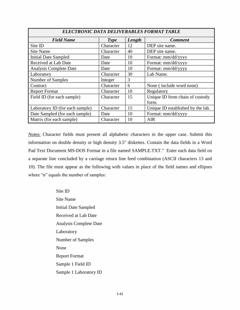
I-41
ELECTRONIC DATA DELIVERABLES FORMAT TABLE
Field Name Type Length Comment
Site ID Character 12 DEP site name.
Site Name Character 40 DEP site name.
Initial Date Sampled Date 10 Format: mm/dd/yyyy
Received at Lab Date Date 10 Format: mm/dd/yyyy
Analysis Complete Date Date 10 Format: mm/dd/yyyy
Laboratory Character 30 Lab Name.
Number of Samples Integer 3
Contract Character 6 None ( include word none)
Report Format Character 10 Regulatory
Field ID (for each sample) Character 15 Unique ID from chain of custody
form.
Laboratory ID (for each sample) Character 15 Unique ID established by the lab.
Date Sampled (for each sample) Date 10 Format: mm/dd/yyyy
Matrix (for each sample) Character 10 AIR
Notes: Character fields must present all alphabetic characters in the upper case. Submit this
information on double density or high density 3.5" diskettes. Contain the data fields in a Word
Pad Text Document MS-DOS Format in a file named SAMPLE.TXT." Enter each data field on
a separate line concluded by a carriage return line feed combination (ASCII characters 13 and
10). The file must appear as the following with values in place of the field names and ellipses
where “n” equals the number of samples:
Site ID
Site Name
Initial Date Sampled
Received at Lab Date
Analysis Complete Date
Laboratory
Number of Samples
None
Report Format
Sample 1 Field ID
Sample 1 Laboratory ID

I-42
Sample 1 Date Sampled
Sample 1 Matrix
Sample 2 Field ID
Sample 2 Laboratory ID
Sample 2 Date Sampled
Sample 2 Matrix
Sample n Field ID
Sample n Laboratory ID
Sample n Date Sampled
Sample n Matrix
Method TO-15 Units Conversion Table - This table is in a Microsoft Excel spreadsheet and
provides an imbedded calculation to convert the ppbv results obtained by the laboratory to
g/m3. A separate excel work sheet within one Microsoft Excel file must be provided for each
field sample. The name for each work sheet inserted at the bottom must be the Laboratory File
Identification number not the Field Sample Identification Number. Additionally, a separate
printed worksheet must be provided for each field sample directly behind the case narrative for
each sample. The order of the compounds on the table can be revised to the order of elution of
the compounds from the GC/MS. The files must be named with the SRP Identification Number
and end with “.xls”. Electronic copies of the Conversion Table are posted on at
http://www.nj.gov/dep/srp/guidance/vaporintrusion.
Method TO-17 Units Conversion Table - This table is in a Microsoft Excel spreadsheet and
provides an imbedded calculation to convert the nanograms results obtained by the laboratory to
g/m3. A separate excel work sheet within one Microsoft Excel file must be provided for each
field sample. The name for each work sheet inserted at the bottom must be the Laboratory File
Identification number not the Field Sample Identification Number. Additionally a separate
printed worksheet must be provided for each field sample directly behind the case narrative for
each sample. The order of the compounds on the table can be revised to the order of elution of
the compounds from the GC/MS. The files must be named with the SPR Identification Number

I-43
and end with “.xls”. Electronic copies of the Conversion Table are posted at
http://www.nj.gov/dep/srp/guidance/vaporintrusion.
For compounds that are not listed in the tables, the laboratory is to add these compounds at the
end of the current list of compounds.
Hazsites Electronic Data Submission of Results
A) Acceptable Format
The investigator shall use the following format to electronically deliver the analytical
results. This information shall be delivered on a separate diskette. Results of laboratory
analysis are to be electronically submitted in one of the following ways.
The HAZSITE Database is a stand-alone data collection application that contains all the
required fields, help screens, and built-in checks to ensure data meets the required format.
If the laboratory uses this option, it must first create DATASET and SAMPLE records
from information provided by NJDEP and then create the RESULTS records. A diskette
copy of this application, identified as HazSite4 LATEST VERSION, may be requested
from NJDEP by calling (609) 292-9418 or the document can be downloaded from the
DEP Home Page at http://www.state.nj.us/dep/srp/hazsite.
The Electronic Data Submission Application (EDSA) contains built-in checks to ensure
data meets the required format. If the laboratory uses this option, it must first create
DATASET and SAMPLE records from information provided by DEP, and then create
the RESULTS records. A CD containing this application and other support tools of this
application, may be requested from DEP by calling (609) 292-9418, or the hazsite
materials can be downloaded from the DEP Home Page at
http://www.state.nj.us/dep/srp/hazsite.

I-44
B) Analytes/Parameters
The analytes and parameters for which results are being submitted must appear exactly as
they appear in the DEP internal system. If using the HazSite4 LATEST VERSION
option, the analytes/parameters are included in the HazSite4 LATEST VERSION as a
"pick list". If using the .wk1 or .dbf file format option for submission of results, the
analytes/parameters list can be obtained from the NJDEP in hard copy and must be used
by the laboratory. This file may be obtained from NJDEP in a hard copy format and or as
an ELECTRONIC file on diskette by calling 609-292-9418.
C) Additional Data provided by the investigator
The investigator will provide to the laboratory the first three fields required for the
electronic submission of results. These fields are SRP ID, Sample Date, and Sample
Number.
D) Data Transmission
All physical media sent to the department must be in an IBM-Compatible format. Files
are to be transmitted on 3.5" 1.44 IBM formatted diskettes.
The laboratory should transmit the diskette to the investigator for that sample batch along
with the other documents submitted as part of the required deliverables. A transmittal
letter indicating the facts of the electronic data submittal must accompany the official
hard copy submission of the Data Report. The memo should specify exactly what data is
being submitted. The diskette should be labeled on its exterior as "Analytical Results"
and include the Site Name and Data of Submittal.
E) Discussion of Fields
For clarification on the definition of fields, please see the SRP-Electronic Data
Interchange (EDI) manual, at http://www.nj.gov/dep/srp/hazsite/docs/.
I-45
F) Additional Field Requirements
The last column in the Hazsites results file format is labeled "QAQC". The laboratory
will populate this field with the Sample Delivery Group Number that is assigned to
particular group of samples. The field must be populated for every compound. The field
length is currently a maximum of 15 characters in length.
Two additional fields are added following the field labeled "QAQC". These fields are to
be used to report the analytical data as it comes off the instrument. The laboratory will
populate both fields for every compound. The field lengths for both columns are currently
a maximum of 15 characters in length.
The first field is named "UNCCONC" and will used for reporting the "uncorrected" result
value. This is a numeric field only with a decimal point as needed. This is the
concentration that is reported off the instrument prior to conversion to g/m3.
The second field is named "UNCUNIT" and will be used for the "uncorrected" results
unit value. This is also used for the detection limit units. The field will be populated with
"ppbv” (Method TO-15) and “ngs” (Method TO-17) as the uncorrected result
concentration unit.
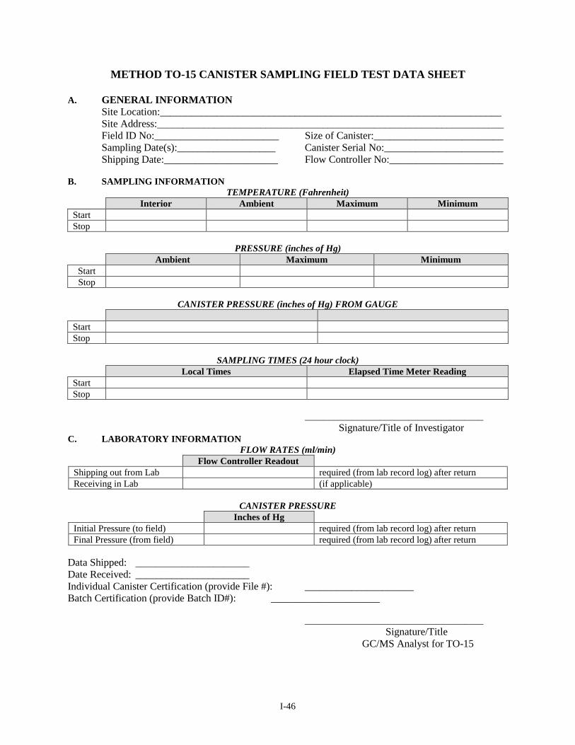
I-46
METHOD TO-15 CANISTER SAMPLING FIELD TEST DATA SHEET
A. GENERAL INFORMATION
Site Location:__________________________________________________________________
Site Address:___________________________________________________________________
Field ID No:________________________ Size of Canister:_________________________
Sampling Date(s):___________________ Canister Serial No:_______________________
Shipping Date:______________________ Flow Controller No:______________________
B. SAMPLING INFORMATION
TEMPERATURE (Fahrenheit)
Interior Ambient Maximum Minimum
Start
Stop
PRESSURE (inches of Hg)
Ambient Maximum Minimum
Start
Stop
CANISTER PRESSURE (inches of Hg) FROM GAUGE
Start
Stop
SAMPLING TIMES (24 hour clock)
Local Times Elapsed Time Meter Reading
Start
Stop
______________________________________
Signature/Title of Investigator C. LABORATORY INFORMATION
FLOW RATES (ml/min)
Flow Controller Readout
Shipping out from Lab required (from lab record log) after return
Receiving in Lab (if applicable)
CANISTER PRESSURE
Inches of Hg
Initial Pressure (to field) required (from lab record log) after return
Final Pressure (from field) required (from lab record log) after return
Data Shipped: ______________________
Date Received: ______________________
Individual Canister Certification (provide File #): _____________________
Batch Certification (provide Batch ID#): _____________________
______________________________________
Signature/Title
GC/MS Analyst for TO-15

I-47
COMPENDIUM METHOD TO-17
FIELD TEST DATA SHEET
A. GENERAL INFORMATION
Project________________________________ Date(s) Sampled:_______________
Site:__________________________________ Time Period Sampled:___________
Location:____________________________ Operator:_________________________
Instrument Model No:__________________ Calibrated By:_____________________
Pump Serial No:___________________________ Rain:_______Yes________No
ADSORBENT CARTRIDGE INFORMATION:
Tube 1 Tube 2
Type: _______________ _______________
Adsorbent: _______________ _______________
Serial No: _______________ _______________
Sample No: _______________ _______________
B. SAMPLING DATA
Tube Id
Sampling
Location
Ambient
Temp,
°F
Ambient
Pressure,
in Hg
Flow Rate (Q),
mL/min
Sampling Period
Total
Sampling
Time, min
Total
Sample
Volume,
L Tube 1 Tube 2 Start Stop
C. FIELD AUDIT
Tube 1 Tube 2
Audit Flow Check Within
10% of Set Point (Y/N)? pre- pre-
_______________ _______________
post- post-
CHECKED BY:_____________________________________
DATE:____________________________________________