Embed Size (px)
Citation preview

Op
era
tion
Ma
nu
al
ACM100 Series
ACM100 Series Sub-Micro Drive

Copyright © 2003 byMinarik Corporation
All rights reserved. No part of this manual may be reproduced or transmitted in any formwithout written permission from Minarik Corporation. The information and technical datain this manual are subject to change without notice. Minarik Corporation and itsDivisions make no warranty of any kind with respect to this material, including, but notlimited to, the implied warranties of its merchantability and fitness for a given purpose.Minarik Corporation and its Divisions assume no responsibility for any errors that mayappear in this manual and make no commitment to update or to keep current theinformation in this manual. MVD011403
Printed in the United States of America.

3ACM100 Series User’s Manual
Table of Contents
1.0 GENERAL . . . . . . . . . . . . . . . . . . . . . . . . . . . . . . .5
2.0 ACM100 DIMENSION . . . . . . . . . . . . . . . . . . . . . .8
3.0 ACM100 MODEL DESIGNATION CODE . . . . . . .10
4.0 ACM100 SPECIFICATIONS . . . . . . . . . . . . . . . . .10
5.0 ACM100 RATINGS . . . . . . . . . . . . . . . . . . . . . . . .11
6.0 INSTALLATION . . . . . . . . . . . . . . . . . . . . . . . . . .12
7.0 INPUT AC POWER REQUIREMENTS . . . . . . . . .13
8.0 POWER WIRING . . . . . . . . . . . . . . . . . . . . . . . . .17
9.0 ACM100 POWER WIRING DIAGRAM . . . . . . . . .19
10.0 CONTROL WIRING . . . . . . . . . . . . . . . . . . . . . . .20
11.0 ACM100 CONTROL WIRING DIAGRAM . . . . . . .24
12.0 INITIAL POWER UP AND MOTOR ROTATION . .28
13.0 PROGRAMMING THE ACM100 DRIVE . . . . . . . .30
14.0 PARAMETER MENU . . . . . . . . . . . . . . . . . . . . . .36
15.0 DESCRIPTION OF PARAMETERS . . . . . . . . . . .39
16.0 TROUBLESHOOTING . . . . . . . . . . . . . . . . . . . . .59
17.0 ACM100 DISPLAY MESSAGES . . . . . . . . . . . . . .61

4 ACM100 Series User’s Manual
OUTPUT (MOTOR) TERMINALS
CONTROLTERMINALSTRIP
3-DIGIT LEDDISPLAY
INPUT POWERTERMINALS
DC BUSTERMINALS
ELECTRONICPROGRAMMINGMODULE (EPM)
PROGRAMMINGBUTTONS
THE ACM100 SERIES SUB-MICRO DRIVE
5ACM100 Series User’s Manual
1.0 GENERAL
1.1 PRODUCTS COVERED IN THIS MANUALThis manual covers the ACM100 Series Variable Frequency Drive.
1.2 PRODUCT CHANGESMinarik Corporation reserves the right to discontinue or make modificationsto the design of its products without prior notice, and holds no obligation tomake modifications to products sold previously. Minarik Corporation alsoholds no liability for losses of any kind which may result from this action.
1.3 WARRANTY
Minarik Corporation (referred to as “the Corporation”) warrants that itsmanufactured products will be free from defects in workmanship and materialfor twelve (12) months or 3,000 hours, whichever comes first, from date ofmanufacture thereof. Within this warranty period, the Corporation will repairor replace such products that are returned to Minarik Corporation, 901 EastThompson Avenue, Glendale, CA 91201-2011 USA. This warranty shall notapply to any product that has been repaired by unauthorized persons. TheCorporation is not responsible for removal, installation, or any otherincidental expenses incurred in shipping the product to and from the repairpoint. This warranty is in lieu of all other warranties, expressed or implied.No other person, firm, or corporation is authorized to assume, for MinarikCorporation, any other liability in connection with the demonstration or sale ofits products.
1.4 RECEIVINGInspect all cartons for damage which may have occurred during shipping.Carefully unpack equipment and inspect thoroughly for damage or shortage.Report any damage to carrier and/or shortages to supplier. All majorcomponents and connetions should be examined for damage and tightness,with special attention given to PC boards, plugs, knobs and switches.
6 ACM100 Series User’s Manual
1.5 SAFETY INFORMATION
GENERALAll operations concerning installation and commissioning, as well asmaintenance, must be carried out by qualified, skilled personnel (IEC 364and CENELEC HD 384 or DIN VDE 0100 and IEC report 665 or DIN VDE0110 and national regulations for the prevention of accidents must beobserved).
According to this basic safety information, qualified skilled personnel arepersons who are familiar with the installation, assembly, commissioning, andoperation of the product and who have the qualifications necessary for theiroccuptation.
APPLICATIONS AS DIRECTEDDrive controllers are components which are designed for installation inelectrical systems or machinery. They are not to be used as applicances.They are intended exclusively for professional and commercial purposesaccording to EN 61000-3-2.
When installing the drive controllers in machines, commissioning (i.e. thestarting of operation as directed) is prohibited until it is proven that themachine complies with the regulations of the EC Directive 98/37/EC(Machinery Directive); EN 60204 must be observed. Commissioning (i.e.starting of operation as directed) is only allowed when there is compliancewith the EMC Directive (89/336/EEC).
The drive controllers meet the requirements of the Low Voltage Directive72/23/EEC. The harmonised standards of the series EN50178/DIN VDE0160 apply to the controllers.
WARNING! The availability of controllers is restricted according to EN61800-3. These products can cause radio interference in residentail areas.In this case, special measures may be necessary.
ELECTRICAL CONNECTIONWhen working on live drive controllers, applicable national regulations for theprevention of accidents (e.g. VBG 4) must be observed.
The electrical installation must be carried out according to the appropriateregulations (e.g. cable size, fuses, PE connection).

7ACM100 Series User’s Manual
This manual contains information about installation in compliance with EMC(shielding, grounding, filters and cables). These notes must also beobserved for CE-marked controllers. The manufacturer of the system ormachine is responsible for compliance with the required limit valuesdemanded by EMC legislation.
1.6 CUSTOMER MODIFICATIONMinarik Corporation, its sales representatives and distributors, welcome theopportunity to assist our customers in applying our products. Manycustomizing options are available to aid in this function. Minarik Corporationcannot assume responsibility for any modifications not authorized by itsengineering department.

8 ACM100 Series User’s Manual
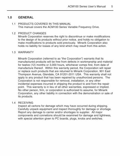
2.0 ACM100 SERIES DIMENSIONS
R
D
P
0.38 [9.5]
0.18 [4.6]
0.69 [17.5]
0.19 [4.8]Dia. Slot
Mounting Tab DetailALL DIMEMSIONS IN INCHES [MILLIMETERS]
W
5.75[146]

9ACM100 Series User’s Manual
2.0 AC-M100 SERIES DIMENSIONS (cont.)
INPUT INPUTkW HP VOLTAGE PHASE MODEL W D P R
0.25 0.33 120 1 ACM100S-0.25 2.88 [74] 3.26 [83] 0.28 [7] 4.37 [111]
0.25 0.33 208/240 1 ACM112S-0.25 2.88 [74] 3.26 [83] 0.28 [7] 4.37 [111]
0.37 0.5 120 1 ACM110S-0.4 2.88 [74] 3.26 [83] 0.28 [7] 4.37 [111]
0.37 0.5 208/240 1 ACM112S-0.4 2.88 [74] 3.26 [83] 0.28 [7] 4.37 [111]
0.37 0.5 208/240 3 ACN112T-0.4 2.88 [74] 3.26 [83] 0.28 [7] 4.37 [111]
0.37 0.5 400/480 3 ACM114T-0.4 2.88 [74] 3.94 [100] 0.80 [20] 4.37 [111]
0.55 0.75 208/240 1 ACM112S-0.55 2.88 [74] 3.63 [92] 0.63 [16] 4.37 [111]
0.75 1 120 1 ACM110S-0.75 3.76 [95] 4.88 [124] 1.50 [38] 4.37 [111]
0.75 1 208/240 1 ACM112S-0.75 2.88 [74] 3.63 [92] 0.63 [16] 4.37 [111]
0.75 1 208/240 3 ACM112T-0.75 2.88 [74] 3.63 [92] 0.63 [16] 4.37 [111]
0.75 1 400/480 3 ACM114T-0.75 2.88 [74] 4.74 [120] 1.60 [41] 4.37 [111]
1.1 1.5 120 1 ACM110S-1.1 3.76 [95] 4.88 [124] 1.50 [38] 4.37 [111]
1.1 1.5 208/240 1 ACM112S-1.1 3.76 [95] 4.88 [124] 1.50 [38] 4.37 [111]
1.1 1.5 208/240 3 ACM112T-1.1 2.88 [74] 5.56 [141] 2.56 [65] 4.37 [111]
1.1 1.5 400/480 3 ACM114T-1.1 2.88 [74] 5.74 [146] 2.56 [65] 4.37 [111]
1.5 2 208/240 1 ACM112S-1.5 3.76 [95] 4.88 [124] 1.50 [38] 4.37 [111]
1.5 2 208/240 3 ACM112T-1.5 2.88 [74] 5.56 [141] 2.56 [65] 4.37 [111]
1.5 2 400/480 3 ACM114T-2.2 2.88 [74] 5.74 [146] 2.56 [65] 4.37 [111]
2.2 3 208/240 1 ACM112S-2.2 3.76 [95] 5.53 [140] 2.18 [55] 4.37 [111]
2.2 3 208/240 3 ACM112T-2.2 3.76 [95] 5.53 [140] 2.18 [55] 4.37 [111]
2.2 3 400/480 3 ACM114T-2.2 3.76 [95] 6.74 [171] 3.40 [86] 4.37 [111]
4.0 5 208/240 3 ACM112T-3.7 3.76 [95] 6.74[171] 3.40 [86] 3.25 [83]
4.0 5 400/480 3 ACM114T-3.7 3.76 [95] 6.74[171] 3.40 [86] 3.25 [83]
10 ACM100 Series User’s Manual
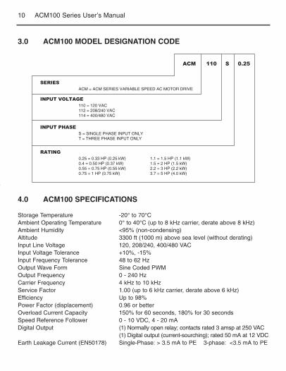
3.0 ACM100 MODEL DESIGNATION CODE
4.0 ACM100 SPECIFICATIONS
SERIES
ACM 110 S 0.25
INPUT VOLTAGE
RATING
INPUT PHASE
ACM = ACM SERIES VARIABLE SPEED AC MOTOR DRIVE
110 = 120 VAC112 = 208/240 VAC114 = 400/480 VAC
0.25 = 0.33 HP (0.25 kW)0.4 = 0.50 HP (0.37 kW)0.55 = 0.75 HP (0.55 kW)0.75 = 1 HP (0.75 kW)
1.1 = 1.5 HP (1.1 kW)1.5 = 2 HP (1.5 kW)2.2 = 3 HP (2.2 kW)3.7 = 5 HP (4.0 kW)
S = SINGLE PHASE INPUT ONLYT = THREE PHASE INPUT ONLY
Storage Temperature -20° to 70°CAmbient Operating Temperature 0° to 40°C (up to 8 kHz carrier, derate above 8 kHz)Ambient Humidity <95% (non-condensing)Altitude 3300 ft (1000 m) above sea level (without derating)Input Line Voltage 120, 208/240, 400/480 VACInput Voltage Tolerance +10%, -15%Input Frequency Tolerance 48 to 62 HzOutput Wave Form Sine Coded PWMOutput Frequency 0 - 240 HzCarrier Frequency 4 kHz to 10 kHzService Factor 1.00 (up to 6 kHz carrier, derate above 6 kHz)Efficiency Up to 98%Power Factor (displacement) 0.96 or betterOverload Current Capacity 150% for 60 seconds, 180% for 30 secondsSpeed Reference Follower 0 - 10 VDC, 4 - 20 mADigital Output (1) Normally open relay; contacts rated 3 amsp at 250 VAC
(1) Digital output (current-sourching); rated 50 mA at 12 VDCEarth Leakage Current (EN50178) Single-Phase: > 3.5 mA to PE 3-phase: <3.5 mA to PE

11ACM100 Series User’s Manual
5.0 ACM100 RATINGS
OUTPUT(3 PHASE)
HP KwINPUTPHASE
CURRENT(AMPS)
POWER(Kva)
CURRENT(AMPS)
0 - 230 VACACM110S-0.25 0.33 0.25 1 6.8 0.8 1.7 29ACM110S-0.4 0.5 0.37 1 9.2 1.1 2.4 33
ACM110S-0.75 1 0.75 1 16.6 2 4.2 57ACM110S-1.1 1.5 1.1 1 24 2.9 6 86
0-208/230 VACACM112S-0.25 0.33 0.25 1 3.9/3.4 0.8 1.9/1.7 23ACM112S-0.4 0.5 0.37 1 5.8/5.0 1.2 2.8/2.4 31ACM112T-0.4 0.5 0.37 3 3.1/2.7 1.1 2.8/2.4 31
ACM112S-0.55 0.75 0.55 1 6.9/6.0 1.4 3.7/3.2 34ACM112S-0.75 1 0.75 1 10.6/9.2 2.2 4.8/4.2 47ACM112T-0.75 1 0.75 3 5.8/5.1 2.1 4.8/4.2 47ACM112S-1.1 1.5 1.1 1 13.9/12.0 2.9 6.9/6.0 68ACM112T-1.1 1.5 1.1 3 8.0/6.9 2.9 6.9/6.0 68ACM112S-1.5 2 1.5 1 18.4/16.0 3.1 8.1/7.0 71ACM112T-1.5 2 1.5 3 9.1/7.9 3.3 8.1/7.0 71ACM112S-2.2 3 2.2 1 24/21 4.1 11.0/9.6 108ACM112T-2.2 3 2.2 3 12.4/10.8 4.5 11.0/9.6 108ACM112T-3.7 5 4 3 19.6/17.1 7.1 17.5/15.2 173
0-400/460 VACACM114T-0.4 0.5 0.37 3 1.6/1.4 1.1 1.3/1.1 31
ACM114T-0.75 1 0.75 3 3.0/2.5 2.1 2.5/2.1 47ACM114T-1.1 1.5 1.1 3 4.3/3.6 3.0 3.6/3.0 58ACM114T-1.5 2 1.5 3 4.8/4.0 3.3 4.1/3.4 63ACM114T-2.2 3 2.2 3 6.4/5.4 4.5 5.8/4.8 92ACM114T-3.7
NOTE 1: See Section 3.0 for model number breakdown.NOTE 2: Values are worst-case (not typical) for 6 kHz carrier frequency at full speed and full load.
5 4 3 10.6/8.8 7.1 9.4/7.8 155
400/480 VAC INPUT MODELS 400/480 VAC
120 VAC INPUT MODELS 120 VAC
208/240 VAC INPUT MODELS 208/240 VAC
FOR MOTORSRATED INPUT (50-60 Hz) HEAT LOSS
(WATTS)(NOTE 2)
ACM MODEL NUMBER(NOTE 1)

12 ACM100 Series User’s Manual
6.0 INSTALLATION
NOTE: ACM100 Series drives are intended for inclusion within otherequipment, by professional electrical installers according to EN 61000-3-2.They are not intended for stand-alone operation.
WARNING: Drives must not be installed where subjected to adverseenvironmental conditions such as: combustible, oily, or hazardous vapors ordust; excessive moisture or dirt; vibration; excessive ambient temperatures.Consult Minarik Corporation for more information on the suitability of a driveto a particular environment.
ACM100 Series modes are suitable for UL pollution degree 2 environment only,and MUST be installed in an electrical enclosure which will provide completemechanical protection and will maintain the internal temperature within the drive’sambient operating temperature rating. All drive models MUST be mounted in avertical position for proper heatsink cooling.
Maintain a minimum spacing around the drive of at least 1 inch (25 mm) on eachside and 2 inches (50 mm) on the top and bottom. Allow more spacing if the driveis mounted next to other heat-producing equipment. Do not mount drives aboveother drives or heat producing equipment. Fans or blowers should be used toinsure proper cooling in tight quarters.
In order to properly size an enclosure, the heat generated by the drive(s) must beknown. Refer to the HEAT LOSS column in Section 5.0 ACM100 RATINGS. Anenclosure manufacturer can then determine the required enclosure size based onthe total heat generated inside the enclosure (from the drive(s) and other heatsources), the maximum allowable temperature inside the enclosure, the maximumambient temperature outside the enclosure, and the enclosure properties.
The ACM100 Series is UL approved for solid state motor overload protection.Therefore, a separate thermal overload relay is not required for single motorapplications.
WARNING! Severe damage to the drive can result if it is operated after a longperiod of storage or inactivity without reforming the DC bus capacitors!
6.1 INSTALLATION AFTER A LONG PERIOD OF STORAGE
13ACM100 Series User’s Manual
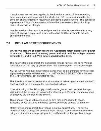
7.0 INPUT AC POWER REQUIREMENTS
WARNING! Hazard of electrical shock! Capacitors retain charge after poweris removed. Disconnect incoming power and wait until the voltage betweenterminals B+ and B- is 0 VDC before servicing the drive.
If input power has not been applied to the drive for a period of time exceedingthree years (due to storage, etc.), the electrolytic DC bus capacitors within thedrive can change internally, resulting in excessive leakage current. This can resultin premature failure of the capacitors if the drive is operated after such a longperiod of inactivity or storage.
In order to reform the capacitors and prepare the drive for operation after a longperiod of inactivity, apply input power to the drive for 8 hours prior to actuallyoperating the motor.
The input voltage must match the nameplate voltage rating of the drive. Voltagefluctuation must not vary by greater than 10% overvoltage or 15% undervoltage.
NOTE: Drives with dual input voltage ratings must be programmed for the propersupply voltage (refer to Parameter 01 - LINE VOLTAGE SELECTION in Section15.0 - DESCRIPTION OF PARAMETERS).
The drive is suitable for use on a circuit capable of delivering not more than 5,000RMS symmetrical amperes at the drive’s rated voltage.
If the kVA rating of the AC supply transformer is greater than 10 times the inputkVA rating of the drive(s), an isolation transformer, or 2-3% input line reactor mustbe added to the line side of the drive(s).
Three phase voltage imbalance must be less than 2.0% phase to phase.Excessive phase to phase imbalance can cause severe damage to the drive.
Motor voltage should match line voltage in normal applications. The drive’smaximum output voltage will equal the input voltage. Use extreme caution whenusing a motor with a voltage rating which is different from the input line voltage.

14 ACM100 Series User’s Manual
7.1 INPUT VOLTAGE RATINGS
ACM110S Series drives are rated for 120 VAC single phase, 50-60 Hz input. Thedrive will function with input voltage of 120 VAC (+10%, -15%) at 48 to 62 Hz.
ACM112S Series drives are rated for 208/240 VAC, single phase, 50-60 Hz input.The drive will function with input voltage of 208 to 240 VAC (+10%, -15%), at 48to 62 Hz.
ACM112T Series drives are rated for 208/240 VAC, three phase, 50-60 Hz input.The drive will function with input voltage of 208 to 240 VAC (+10%, -15%) at 48 to62 Hz.
ACM114T Series drives are rated for 400/480 VAC, three phase, 50-60 Hz input.The drive will function with input voltage of 400 to 480 VAC (+10%, -15%) at 48 to62 Hz.
NOTE: Parameter 01 - LINE VOLTAGE SELECTION must be programmedaccording to the applied input voltage. See Section 15.0 - DESCRIPTION OFPARAMETERS.
7.2 INPUT FUSING AND DISCONNECT REQUIREMENTS
A circuit breaker or a disconnect switch with fuses must be provided inaccordance with the National Electric Code (NEC) and all local codes. Refer tothe following tables for proper fuse/circuit breaker ratings and wire sizes.
ACM110S-0.25 10A ACM112T-0.4 10A ACM114T-0.4 10A
ACM110S-0.4 15A ACM112T-0.75 10A ACM114T-0.75 10A
ACM110S-0.75 25A ACM112T-1.1 12/10A ACM114T-1.1 10A
ACM110S-1.1 35A ACM112T-1.5 15/12A ACM114T-1.5 10A
ACM112T-2.2 20/15A ACM114T-2.2 10A
ACM112T-3.7 30/25A ACM114T-3.7 15/12A
120 VAC 1 PHASE 208/240 VAC 3 PHASE 400/480 VAC 3 PHASE
INPUT FUSE & CIRCUIT BREAKER RATINGS
15ACM100 Series User’s Manual
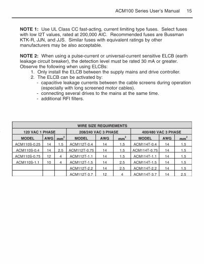
NOTE 1: Use UL Class CC fast-acting, current limiting type fuses. Select fuseswith low I2T values, rated at 200,000 AIC. Recommended fuses are BussmanKTK-R, JJN, and JJS. Similar fuses with equivalent ratings by othermanufacturers may be also acceptable.
NOTE 2: When using a pulse-current or universal-current sensitive ELCB (earthleakage circuit breaker), the detection level must be rated 30 mA or greater.Observe the following when using ELCBs:
1. Only install the ELCB between the supply mains and drive controller.2. The ELCB can be activated by:
- capacitive leakage currents between the cable screens during operation(especially with long screened motor cables).
- connecting several drives to the mains at the same time.- additional RFI filters.
MODEL AWG mm2 MODEL AWG mm
2 MODEL AWG mm2
ACM110S-0.25 14 1.5 ACM112T-0.4 14 1.5 ACM114T-0.4 14 1.5
ACM110S-0.4 14 2.5 ACM112T-0.75 14 1.5 ACM114T-0.75 14 1.5
ACM110S-0.75 12 4 ACM112T-1.1 14 1.5 ACM114T-1.1 14 1.5
ACM110S-1.1 10 4 ACM112T-1.5 14 2.5 ACM114T-1.5 14 1.5
ACM112T-2.2 14 2.5 ACM114T-2.2 14 1.5
ACM112T-3.7 12 4 ACM114T-3.7 14 2.5
208/240 VAC 3 PHASE120 VAC 1 PHASE 400/480 VAC 3 PHASE
WIRE SIZE REQUIREMENTS

16 ACM100 Series User’s Manual
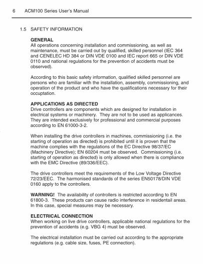
7.3 INSTALLATION ACCORDING TO EMC REQUIREMENTS
The ACM100 Series can be installed to meet the European standards forElectromagnetic Compatibility (EMC) requirements. These requirements governthe permissible electromagneticemissions and immunity, bothradiated and conducted, of adrive system.
The EMC requirements apply tothe final installation in itsentirety, not to the individualcomponents used. Becauseevery installation is different, therecommended installationshould follow these guidelinesas a minimum. Additionalequipment (such as ferrite coreabsorbers on power conductors)or alternative wiring practicesmay be required to meetconformance in someinstallations.
Filter: The input to the drive ( orgroup of drives) must include afilter to reduce the electricalnoise reflected back to the ACLine. The ACM100 series drivecan be installed to meet thesesame standards when used withan appropriately installedexternal line filter.
Installation: Shielded cablemust be used for all control andpower cables and exposed wiring must be kept as short as possible. The figureabove shows the control cable (B) and motor cable (C) with the shield groundedwith clamps (A) to a grounded, electrically conductive mounting panel (D). Themotor cable must be of a low capacitance specification:
core/core < 75 pF/m, core/shield < 150 pF/m

17ACM100 Series User’s Manual
8.0 POWER WIRING
Note drive input and output current ratings and check applicable electrical codesfor required wire type and size, grounding requirements, over-current protection,and incoming power disconnect, before wiring the drive. Size conservatively tominimize voltage drop.
Strip off 0.20 to 0.25 inches (5 to 6 mm) of insulation for input power, outputpower, and DC Bus wiring. The input power, output power, and DC Bus terminalsmust be tightened to a torque of 4.5 lb-in (0.5 Nm).
Input fusing and a power disconnect switch or contactor MUST be wired in serieswith termianls L1 and L2/N (on single-phase input modesl), or terminals L1, L2,and L3 (on three-phase input models). This disconnect must be used to powerdown the drive when servicing, or when the drive is not to be operated for a longperiod of time, but should not be used to start and stop the motor.
Repetitive cycling of a disconnect or input contactor (more than once every twominutes) may cause damage to the drive.
WARNING! Hazard of electrical shock! Capactors retain charge after poweris removed. Disconnect incoming power and wait until the voltage betweenterminals B+ and B- is 0 VDC before servicing the drive.

18 ACM100 Series User’s Manual
On single phase input models, wire the input power to terminals L1 and L2/N. Onthree phase input models, wire the input power to terminals L1, L2, and L3. Referto Section 9.0 - ACM100 POWER WIRING DIAGRAM.
All three power output wires, from terminals U, V, and W to the motor, must bekept tightly bundled and run in a separate conduit away from all other power andcontrol wiring.
It is not recommended to install contactors or disconnect switches between thedrive and motor. Operating such devices while the drive is running can potentiallycause damage to the drive’s power components. If such a device is required, itshould only be operated when the drive is in a STOP state. If there is potential forthe device to be opened while the drive is running, the drive must be programmedfor COAST to stop (see Parameter 4 - STOP METHOD), and an auxiliary contacton the device must be interlocked with the drive’s run circuit. This will give thedrive a stop command at the same time the device opens, and will not allow thedrive to start again until the device is closed.
8.1 INPUT AND OUTPUT WIRING

19ACM100 Series User’s Manual
9.0 ACM POWER WIRING DIAGRAM
NOTES:1. WIRE AND GROUND IN ACCORDANCE WITH NEC OR CEC, AND ALL
APPLICABLE LOCAL CODES.2. Motor wires MUST be run in a separate steel conduit away from control wiring
and incoming AC power wiring.3. Do not install contactors between the drive and the motor without consulting
Minarik Corporation for more information. Failure to do so may result in drivedamage.
4. Use only UL and CSA listed and approved wire.5. Minimum wire voltage rating is 300 V for 120, 208, and 240 VAC systems, and
600 V for 400 and 480 VAC systems.6. Wire gauge must be based on a minimum of 125% of the rated input/output
current of the drive, and a minimum 75°C insulation rating. Use copper wire only.7. Strip off 0.20 to 0.25 inches (5 to 6 mm) of insulation for input power, output
power, and DC Bus wiring.
INPUT(SINGLE-PHASE MODELS ONLY)
OUTPUT (ALL MODELS)
INPUT ACVOLTAGE
L1 L2/N B- B+PE
V
PES
3 PHASEAC MOTOR
W PE PEU
INPUT(THREE-PHASE MODELS ONLY)
INPUT ACVOLTAGE
L1 L2 L3 B- B+
PE Lugon Heatsink
PES
WARNING! DO NOT connectincoming AC power to outputterminals U, V, W, or terminalsB+, B-. This will result in severedamage to the drive!

20 ACM100 Series User’s Manual
10.0 CONTROL WIRING
External control wiring MUST be run in a separate conduit away from all otherinput and output power wiring. If control wiring is not kept separate from powerwiring, electrical noise may be generated on the control wiring that will causeerratic drive behavior. Use twisted wires or shielded cable grounded at the drivechassis ONLY. Recommended control wire is Belden 8760 (2-wire) or 8770 (3-wire) or equivalent.
Strip off 0.20 to 0.25 inches (5 to 6 mm) of insulation for control wiring, and torquethe control terminals to 2 lb-in (0.2 Nm). Be careful not to overtorque the controlterminals, as this will cause damage to the terminal strip. This is not coveredunder warranty and can only be repaired by replacing the control board.
10.1 CONTROL WIRING VS. POWER WIRING
The TB-2 terminal is used as circuit common for the analog speed referenceinputs. If necessary TB-2 may be connected to chassis ground.
10.2 TB-2: CIRCUIT COMMON
Current and voltage surges and spikes in the coils of contactors, relays, solenoids,etc, near or connected to the drive, can cause erratic drive operation. Therefore,a snubber circuit should be used on coils associated with the drive. For AC coils,snubbers should consist of a resistor and a capacitor in series across the coil.For DC coils, a free-wheeling or flyback diode should be placed across the coil.Snubbers are typically available from the manufacturer of the device.
10.3 SURGE SUPPRESSION ON RELAYS
There are various control schemes that allow for 2-wire and 3-wire Start/Stopcircuits. Refer to the wiring diagrams in Section 11.0 - ACM CONTROL WIRINGDIAGRAMS
10.4 START/STOP CONTROL

21ACM100 Series User’s Manual
The drive allows for three analog speed reference inputs:
SPEED POT Connect the wiper of a speed pot to terminal TB-5, andconnect the high and low end leads to terminals TB-6 and TB-2, respectively. The speed pot can be 2.5k ohm up to 10kohm.
0 - 10 VDC Wire the positive to terminal TB-5 and the negative to terminalTB-2. TB-5 input impedance is 120 kilohms.
4 - 20 mA Wire the positive to terminal TB-25 and the negative toterminal TB-2. The TB-25 input impedance is 250 ohms.
10.5 SPEED REFERENCE SIGNALS
If an analog speed reference input is used to control the drive speed, terminal TB-13A, 13B, or 13E (Parameter 10, 11, or 12) may be programmed as the inputselect for the desired analog input signal. When that TB-13 terminal is thenclosed to TB-11, the drive will follow the selected analog speed reference input.
If an analog speed reference input is not selected on the terminal strip using TB-13A, 13B, or 13E, speed control will default to STANDARD mode, which isgoverned by the setting of STANDARD SPEED SOURCE (Parameter 05). TheSTANDARD SPEED SOURCE can be the and buttons on the front of thedrive, PRESET SPEED #1 (Parameter 31), a 0 - 10 VDC signal, or 4 - 20 mAsignal.
0 - 10 VDC and 4 - 20 mA INPUT SIGNALS
TB-13A, TB-13B, and TB-13 E can all be programmed to select a 0 - 10VDC or 4 - 20 mA analog speed preference input.
PRESET SPEEDS
TB-13A can be programmed to select PRESET SPEED #1 (04), TB-13B toselect PRESET SPEED #2 (04), and TB-13E to select PRESET SPEED #3(04). There are a total of seven preset speeds, which are activated bydifferent combinations of contact closures between TB-13A, 13B, 13E, andTB-11. Refer to Parameters 31-37 in Section 15.0 - DESCRIPTION OFPARAMETERS.
10.6 SPEED REFERENCE SELECTION

22 ACM100 Series User’s Manual
JOG
TB-13B can be programmed to select either JOG FORWARD (07) or JOGREVERSE (08). The Jog speed is set by PRESET SPEED #2 (Parameter32). Close TB-13B to TB-11 to JOG, and open the contact to STOP.
NOTE: If the drive is commanded to JOG while running, the drive will enter JOGmode and run at PRESET SPEED #2. When the JOG command is removed, thedrive will STOP.
MOTOR OPERATED POT (MOP) FLOATING POINT CONTROL
TB-13B and TB-13E are used for this function, which controls the drivespeed using contacts wired to the terminal strip. Program TB-13B forDECREASE FREQ (05), and program TB-13E for INCREASE FREQ (05).Closing TB-13B to TB-11 will cause the speed setpoint to increase until thecontact is opened. The INCREASE FREQ function will only operate whilethe drive is running.
NOTE: If TB-13A, TB-13B, and TB-13E are all programmed to select speedreferences, and two or three of the terminals are closed to TB-11, the higherterminal has priority and will override the others. For example, if TB-13A isprogrammed to select 0 - 10 VDC, and TB-13E is programmed to select PRESETSPEED #3, closing both terminals to TB-11 will cause the drive to respond toPRESET SPEED #3, because TB-13E overrides TB-13A.
The exception to this is the MOP function, which requires the use of TB-13Band TB-13E. This leaves TB-13A to be used for some other function. If TB-13A is programmed for a speed reference, and TB-13A is closed to TB-11,TB-13A will override the MOP function.
WARNING! When operating in JOG mode, the STOP signal and theAUXILIARY STOP function (see Parameters 10-12) WILL NOT stop the drive.To stop the drive, remove the JOG command.
JOG REVERSE will operate the drive in reverse rotation even if ROTATIONDIRECTION (Parameter 17) is set to FORWARD ONLY.

23ACM100 Series User’s Manual
There is one Form A relay at terminals TB-16 and TB-17. Relay contacts arerated 3 amps at 250 VAC.
Terminal TB-13E can also be configured as a digital output. This output circuit isa current-sourcing type rated at 12 VDC and 50 mA maximum.
The Form A relay and digital output can be programmed to indicate any of thefollowing: RUN, FAULT, INVERSE FAULT, FAULT LOCKOUT, AT SPEED,ABOVE PRESET SPEED #3, CURRENT LIMIT, AUTO SPEED MODE, andREVERSE. Refer to Parameters 06 and 12 in Section 15.0 - DESCRIPTION OFPARAMETERS.
The digram below illustrates how TB-13E, when configured as a digital output, canbe used to drive an external relay:
10.7 DRIVE STATUS DIGITAL OUTPUTS
TB-13E
DIODE SNUBBER(1N4148 or Equivalent)
RELAY COIL
AC
M1
00
TE
RM
INA
L S
TR
IP
TB-2
24 ACM100 Series User’s Manual
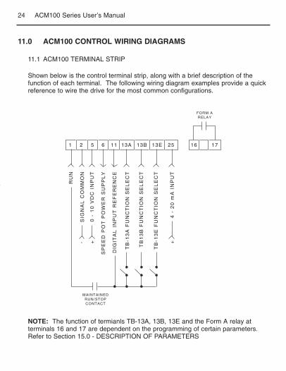
11.0 ACM100 CONTROL WIRING DIAGRAMS
Shown below is the control terminal strip, along with a brief description of thefunction of each terminal. The following wiring diagram examples provide a quickreference to wire the drive for the most common configurations.
NOTE: The function of termianls TB-13A, 13B, 13E and the Form A relay atterminals 16 and 17 are dependent on the programming of certain parameters.Refer to Section 15.0 - DESCRIPTION OF PARAMETERS
11.1 ACM100 TERMINAL STRIP
1 2 5 6 11 13A 13B 13E 25 16 17
RU
N
SIG
NA
L C
OM
MO
N
0 -
10
VD
C I
NP
UT
SP
EE
D P
OT
PO
WE
R S
UP
PL
Y
DIG
ITA
L I
NP
UT
RE
FE
RE
NC
E
TB
-13
A F
UN
CT
ION
SE
LE
CT
TB
13
B F
UN
CT
ION
SE
LE
CT
TB
-13
E F
UN
CT
ION
SE
LE
CT
4 -
20
mA
IN
PU
T++-
MAINTAINEDRUN/STOPCONTACT
FORM ARELAY

25ACM100 Series User’s Manual
NOTES:
1. Close TB-1 to TB-11 to RUN, and open to STOP. TB-1 functions as a RUNinput for two-wire start/stop circuits, and a STOP input for three-wire start/stopcircuits. Refer to Section 11.3.
2. If reverse direction is required, set ROTATION (Parameter 17) to FORWARDAND REVERSE (02), and program TB-13A (Parameter 10) to RUN REVERSE(06). Close TB-13A to TB-11 to RUN in the reverse direction, and open toSTOP.
3. For 0 - 10 VDC or 4 - 20 mA speed control, set STANDARD SPEED SOURCE(Parameter 05) to 0 - 10 VDC (03) or 4 - 20 mA (04).
11.2 TWO-WIRE START/STOP CONTROL
1 2 5 6 11 13A 13B 13E 25 16 17
RU
N
SIG
NA
L C
OM
MO
N
0 -
10
VD
C I
NP
UT
SP
EE
D P
OT
PO
WE
R S
UP
PL
Y
DIG
ITA
L I
NP
UT
RE
FE
RE
NC
E
TB
-13
A F
UN
CT
ION
SE
LE
CT
(RU
N R
EV
ER
SE
)
TB
13
B F
UN
CT
ION
SE
LE
CT
TB
-13
E F
UN
CT
ION
SE
LE
CT
4 -
20
mA
IN
PU
T+
MAINTAINEDRUN/STOPCONTACT
(FORWARD)
FORM ARELAY
MAINTAINEDRUN/STOPCONTACT
(REVERSE)
+-

26 ACM100 Series User’s Manual
NOTES:
1. Program TB-13E (Parameter 12) for START FORWARD (06).2. If reverse direction is required, set ROTATION (Parameter 17) to FORWARD
AND REVERSE (02), and program TB-13A (Parameter 10) for STARTREVERSE (07).
3. Momentarily close TB-13E to TB-11 to START in the forward direction, or closeTB-13A to TB-11 to START in the reverse direction. Momentarily open TB-1 toTB-11 to STOP the drive.
4. For 0 - 10 VDC or 4 - 20 mA speed control, set STANDARD SPEED SOURCE(Parameter 05) to 0 - 10 VDC (03) or 4 - 20 mA (04).
11.3 THREE-WIRE START/STOP CONTROL
1 2 5 6 11 13A 13B 13E 25 16 17
RU
N
SIG
NA
L C
OM
MO
N
0 -
10
VD
C I
NP
UT
SP
EE
D P
OT
PO
WE
R S
UP
PL
Y
DIG
ITA
L I
NP
UT
RE
FE
RE
NC
E
TB
-13
A F
UN
CT
ION
SE
LE
CT
(ST
AR
T R
EV
ER
SE
)
TB
13
B F
UN
CT
ION
SE
LE
CT
TB
-13
E F
UN
CT
ION
SE
LE
CT
(ST
AR
T F
OR
WA
RD
)
4 -
20
mA
IN
PU
T+
MOMENTARYSTOP CONTACT
FORM ARELAY
MOMENTARYSTART CONTACT
REV FWD
+-

27ACM100 Series User’s Manual
NOTES:
1. For preset speed control, all or some of the TB-13 terminals must beprogrammed as preset speed selects. If only two or three preset speeds arerequired, only two of the TB-13 terminals must be used. Refer to the table inthe description of Parameters 31-37 in Section 15.0
2. Program the PRESET SPEEDS (Parameters 31-37) to the desired values.3. If speed pot control is desired when none of the preset speeds are selected (all
preset speed selects are open to TB-11, set STANDARD SPEED SOURCE(Parameter 05) to 0 - 10 VDC (03).
11.4 PRESET SPEEDS AND SPEED POT(WITH TWO-WIRE START/STOP CONTROL)
1 2 5 6 11 13A 13B 13E 25 16 17
RU
N
SIG
NA
L C
OM
MO
N
0 -
10
VD
C I
NP
UT
SP
EE
D P
OT
PO
WE
R S
UP
PL
Y
DIG
ITA
L I
NP
UT
RE
FE
RE
NC
E
TB
-13
A F
UN
CT
ION
SE
LE
CT
TB
13
B F
UN
CT
ION
SE
LE
CT
TB
-13
E F
UN
CT
ION
SE
LE
CT
MAINTAINEDRUN/STOPCONTACT
SPEEDPOT
FORM ARELAY

28 ACM100 Series User’s Manual
12.0 INITIAL POWER UP AND MOTOR ROTATION
If input power has not been applied to the drive for a period of time exceedingthree years (due to storage, ect.), the electrolytic DC bus capacitors within thedrive can change internally, resulting in excessive leakage current. This can resultin premature failure of the capacitors if the drive is operated after such a longperiod of inactivity or storage.
In order to reform the capacitors and prepare the drive for operation after a longperiod of inactivity, apply input power to the drive for 8 hours prior to actuallyoperating the motor.
Before attempting to operate the drive, motor, and driven equipment, be sure allprocedures pertaining to installation and wiring have been properly followed.
Disconnect the driven load from the motor. Verify that the drive input terminals(L1 and L2/N, or L1, L2, and L3) are wired to the proper input voltage per thenameplate rating of the drive.
Energize the incoming power line. The LED display will flash a three digit number(320 in the example below) that identifies the parameter version contained in thedrive. The display should then read “ - - - “, which indicates that the drive is in aSTOP condition. This is shown below:
WARNING! DO NOT connect incoming AC power to output terminals U, V, andW or terminals B+, B-. Do not continuously cycle input power to the drive morethan once every two minutes. This will result in severe damage to the drive.
WARNING! Hazard of electrical shock! Wait three minutes after disconnectingincoming power before servicing the drive. Capacitors retain charge after thepower is removed.
WARNING! Severe damage to the drive can result if it is operated after a longperiod of storage or inactivity without reforming the DC bus capacitors.

29ACM100 Series User’s Manual
Follow the procedure below to check the motor rotation. This procedure assumesthat the drive has been powered up for the first time, and that none of theparameters have been changed.
1. Use the button to decrease the speed setpoint to 00.0 Hz. The leftdecimal point will illuminate as the speed setpoint is decreased. If the button is held down, the speed setpoint will decrease by tenths of Hz untilthe next whole Hz is reached, and then it will decrease by one Hzincrements. Otherwise, each push of the button will decrease the speedsetpoint by a tenth of a Hz.
Once 00.0 Hz is reached, the display will toggle betwee “00.0” and “ - - - “,which indicates that the drive is in a STOP condition with a speed setpoint of00.0 Hz.
2. Give the drive a START command. This can be done using one of severalwiring methods described in Section 11.0 - ACM CONTROL WIRINGDIAGRAMS. Once the START command is issued, the display will read“00.0”, indicating that the drive is in a RUN condition with a speed setpoint of00.0 Hz.
3. Use the button to increase the speed setpoint until the motor starts torotate. The left decimal point will light as the speed setpoint is increased. Ifthe button is held down, the speed setpoint will increase by tenths of Hzuntil the next whole Hz is reached, and then it will increase by one Hzincrements. Otherwise, each push of the button will increase the speedsetpoint by a tenth of a Hz.
4. If the motor is rotating in the wrong direction, give the drive a STOPcommand and remove power from the drive. Wait three minutes for the buscapacitors to discharge, and swap any two of the motor wires connected toU, V, W.
NOTE: The drive is phase insensitive with respect to incoming line voltage. Thismeans that the drive will operate with any phase sequence of the incoming threephase voltage. Therefore, to change the motor rotation, the phases must beswapped at the drive output terminals or at the motor.

30 ACM100 Series User’s Manual
13.0 PROGRAMMING THE ACM DRIVE
The drive may be programmed by one of two methods: using the three buttons and 3-digit LED display on the front of the drive, or programming the Electronic ProgrammingModule (EPM) using the optional EPM Programmer. This section describesprogramming the drive using the buttons and display, which are shown below:
To enter the PROGRAM mode to access the parameters, press the Mode button. This willactivate the PASSWORD prompt (if the password has not been disabled). The display willread “00” and the upper right-hand decimal point will be blinking, as shown below:
Use the and buttons to scroll to the password, value (the factory default passwordis “225”) and press the Mode button. Once the correct password value is entered, thedisplay will read “P01”, which indicates that the PROGRAM mode has been accessed atthe beginning of the parameter menu (P01 is the first parameter). This is shown below:
DISPLAYBUTTONS
Mode
Press Mode
Display reads "00"
Upper right decimal point blinks
Use and to scroll to the password value
Press Mode to enter password
Parameter menu is accessed at thefirst parameter

31ACM100 Series User’s Manual
Note: If the display flashes “Er”, the password was incorrect, and the process toenter the password must be repeated.
Use the and buttons to scroll to the desired parameter number. In theexample below, Parameter 19 is being displayed, which is the ACCELERATIONTIME of the drive:
Once the desired parameter number is found, press the Mode button to displaythe present parameter setting. The upper right-hand decimal point will beginblinking, indicating that the present parameter setting is being displayed, and thatit can be changed by using the and buttons.
Pressing the Mode will store the new setting and also exit the PROGRAM mode.To change another parameter, press the Mode key again to re-enter thePROGRAM mode (the parameter menu will be accessed at the parameter thatwas last viewed or changed before exiting). If the Mode key is pressed within twominutes of exiting the PROGRAM mode, the password is not required to accessthe parameters. After two minutes, the password must be entered in order toaccess the parameters again.
Use and to scroll to the desired
parameter number (the example is
Parameter 19 - ACCELERATION TIME)
Press Mode to display present
parameter setting (example setting is 20.0)
Upper right decimal point blinks
Use and to change setting
(example setting changed to 30.0)
Press Mode to store new setting

32 ACM100 Series User’s Manual
Parameter settings and the keypad speed command can always be adjusted intenths of unit increments from 0.0 to 99.9. Above 100 however, values can be setin whole units or tenths of units, depending on the setting of Parameter 16 -UNITS ENDING.
If Parameter 16 - UNITS ENDING is set to WHOLE UNITS (02), parameter valuesand the keypad speed command can only be adjusted by whole unit incrementsabove 100. For example, Parameter 19 - ACCELERATION TIME could not be setto 243.7 seconds. It could only be set to 243 or 244 seconds. Likewise, thekeypad speed command (set using the and buttons) could not be set to113.4 Hz. It could only be set to 113 or 114 Hz.
If, however, Parameter 16 - UNITS EDITING is set to TENTHS OF UNITS (01), aparameter values and the keypad speed command can be adjusted in tenths ofunit increments up to a value of 1000 (above 1000, whole unit increments only).Each push of the and button will adjust the value by one tenth of a unit. Ifthe and button is pressed and held, the value will increment by tenths ofunits until the next whole unit is reached, and then the value will increment bywhole units.
When a value above 100 is being adjusted by tenths of units, the value is shiftedto the left by one digit so that the tenths portion of the value can be displayed.This results in the first digit (reading from left to right) of the value disappearingfrom the display. Also, the lower decimal point will blink to indicate that the actualvalue is above 100. Once the value is no longer being adjusted, the value willshift back to the right and the tenths portion of the value will disappear.
In the following example, Parameter 19 - ACCELERATION TIME is presently setto 243.0 seconds, and is being increased to 243.7 seconds.
13.1 SETTING VALUES IN TENTHS OF UNITS ABOVE 100

33ACM100 Series User’s Manual
Press button to see tenths portion
Value shifts to the left ("2" disappears)
Upper right decimal point and lower
decimal point blink
Go to Parameter 19 and press Mode
to see present setting ("243" seconds)
Upper right decimal point blinks
Press button to scroll up to "43.7"
Press Mode to store new value
34 ACM100 Series User’s Manual
Every ACM100 Series drive has an Electronic Programming Module (EPM)installed on the main control board. The EPM stores the user’s parametersettings and special OEM default settings (if programmed). The EPM isremovable, allowing it to be installed in another drive for quick set-up. Forexample, if a drive is being replaced with a new one, the EPM can be taken out ofthe first drive and installed in the new drive. Downtime is minimized because thenew drive does not require programming - it is ready to run when the EPM isinstalled.
The ACM100 Series drive contains two or three sets of parameter values,depending on whether the drive has been programmed with optional OEM defaultsettings. The first set of values is the factory default settings, which arepermanently stored on the main control board and cannot be changed. Thesecond set of values is the user settings, which are stored in the EPM. When thedrive leaves the factory, the user settings are the same as the factory defaultsettings, but the user settings can be changed to configure the drive for aparticular application. The optional third set of values is the OEM default settings,which are also stored in the EPM. OEM default settings are typically used incases where many drives are used for the same application, which requires thatall of the drives have the same parameter settings. The OEM default settingscannot be changed without the optional EPM Programmer. The drive can beprogrammed to operate according to the user settings or the OEM default settings(see Parameter 48 in Section 15.0).
NOTE: The drive will not operate without the EPM installed. The drive willdisplay “F1” if the EPM is missing or damaged.
13.2 ELECTRONIC PROGRAMMING MODULE (EPM)
WARNING! Do not remove the EPM while power is applied to the drive. Thismay result in damage to the EPM and/or drive.

35ACM100 Series User’s Manual
An EPM Programmer is available as an option from Minarik Corporation, whichhas the ability to quickly and easily program many ACM100 Series drives for thesame configuration. Once a “master” EPM is programmed with the desiredparameter settings, the EPM Programmer can copy those settings to other EPMs,allowing many drives to be configured very quickly. Please consult the EPMProgrammer Instruction Manual or contact the factory for more information.
If the OEM settings in the EPM become corrupted, the drive will operate normally,until an attempt is made to perform a RESET OEM using Parameter 48 -PROGRAM SELECTION. The drive will then flash “GF” to indicate that the OEMsettings are no longer valid. This will require that the EPM be programmed usingthe optional EPM Programmer.
If the OEM settings and the user settings are both corrupted, the drive will display“GF” immediately and the drive will require a RESET 60 or RESET 50 usingParameter 48 - PROGRAM SELECTION. Once the RESET is performed, theparameters can then be programmed individually to match the OEM defaultsettings. This will allow the drive to operate as if it were in OEM mode, eventhough it is actually operating in USER mode. Refer to Parameter 48 in Section15.0 - DESCRIPTION OF PARAMETERS.
NOTE: The drive will also display “GF” if a RESET OEM or OPERATE WITHOEM SETTINGS is attempted when the drive is not equipped with the OEMdefault option.

36 ACM100 Series User’s Manual
14.0 PARAMETER MENU
NO. PARAMETER NAME RANGE OF ADJUSTMENT FACTORY DEFAULT
01 LINE VOLTAGE HIGH (01), LOW (02) HIGH (01)
02 CARRIER FREQUENCY 4 kHz (01), 6 kHz (02), 8 kHz (03), 10 kHz (04) 6 kHz (02)
03 START METHOD NORMAL (01), START ON POWER UP (02), NORMAL (01)START WITH DC BRAKE (03)
AUTO RESTART WITH DC BRAKE (04),FLYING RESTART 1 (05),FLYING RESTART 2 (06),FLYING RESTART 3 (07)
04 STOP METHOD COAST (01), COAST WITH DC BRAKE (02), COAST (01)RAMP (03), RAMP WITH DC BRAKE (04)
05 STANDARD SPEED KEYPAD (01), PRESET #1 (02), KEYPAD (01)SOURCE 0 - 10 VDC (03), 4 - 20 mA (04)
06 RELAY OUTPUT NONE (01), RUN (02), FAULT (03), NONE (01)INVERSE FAULT (04), FAULT LOCKOUT (05),AT SET SPEED (06), ABOVE PRESET #3 (07),
CURRENT LIMIT (08), AUTO SPEED (09),REVERSE (10)
10 TB-13A FUNCTION NONE (01), 0 - 10 VDC (02), 4 - 20 mA (03), NONE (01)SELECT PRESET SPEED #1 (04), START FORWARD (05)
RUN REVERSE (06), START REVERSE (07),EXTERNAL FAULT (08),
INVERSE EXT FAULT (09),AUXILIARY STOP (10), ACCEL/DECEL #2 (11)
11 TB13B FUNCTION NONE (01), 0 - 10 VDC (02), 4 - 20 mA (03), NONE (01)SELECT PRESET SPEED #2 (04), DECREASE FREQ (05),
START FORWARD (06), JOG FORWARD (07),JOG REVERSE (08), EXTERNAL FAULT (09),INVERSE EXT FAULT (10), AUX. STOP (11)
ACCEL/DECEL #2 (12), REMOTE KEYPAD (13)
12 TB-13E INPUT NONE (01), 0 - 10 VDC (02), 4 - 20 mA (03), NONE (01)FUNCTIONS PRESET SPEED #3 (04), INCREASE FREQ (05),
START FORWARD (06), EXTERNAL FAULT (07),INVERSE EXT FAULT (08), AUX. STOP (09),
ACCEL/DECEL #2 (10),
TB-13E OUTPUT RUN (11), FAULT (12), INVERSE FAULT (13), NONE (01)FUNCTIONS FAULT LOCKOUT (14), AT SET SPEED (15),
ABOVE PRESET #3 (16), CURRENT LIMIT (17),AUTO SPEED (18), REVERSE (19),
DYNAMIC BRAKING (20),
OTHER FUNCTIONS REMOTE KEYPAD (21) NONE (01)
37ACM100 Series User’s Manual
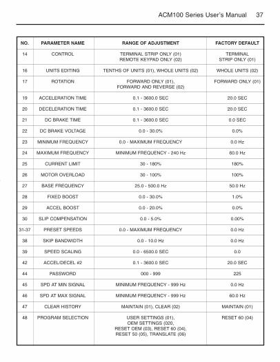
NO. PARAMETER NAME RANGE OF ADJUSTMENT FACTORY DEFAULT
14 CONTROL TERMINAL STRIP ONLY (01) TERMINALREMOTE KEYPAD ONLY (02) STRIP ONLY (01)
16 UNITS EDITING TENTHS OF UNITS (01), WHOLE UNITS (02) WHOLE UNITS (02)
17 ROTATION FORWARD ONLY (01), FORWARD ONLY (01)FORWARD AND REVERSE (02)
19 ACCELERATION TIME 0.1 - 3600.0 SEC 20.0 SEC
20 DECELERATION TIME 0.1 - 3600.0 SEC 20.0 SEC
21 DC BRAKE TIME 0.1 - 3600.0 SEC 0.0 SEC
22 DC BRAKE VOLTAGE 0.0 - 30.0% 0.0%
23 MINIMUM FREQUENCY 0.0 - MAXIMUM FREQUENCY 0.0 Hz
24 MAXIMUM FREQUENCY MINIMUM FREQUENCY - 240 Hz 60.0 Hz
25 CURRENT LIMIT 30 - 180% 180%
26 MOTOR OVERLOAD 30 - 100% 100%
27 BASE FREQUENCY 25.0 - 500.0 Hz 50.0 Hz
28 FIXED BOOST 0.0 - 30.0% 1.0%
29 ACCEL BOOST 0.0 - 20.0% 0.0%
30 SLIP COMPENSATION 0.0 - 5.0% 0.00%
31-37 PRESET SPEEDS 0.0 - MAXIMUM FREQUENCY 0.0 Hz
38 SKIP BANDWIDTH 0.0 - 10.0 Hz 0.0 Hz
39 SPEED SCALING 0.0 - 6500.0 SEC 0.0
42 ACCEL/DECEL #2 0.1 - 3600.0 SEC 20.0 SEC
44 PASSWORD 000 - 999 225
45 SPD AT MIN SIGNAL MINIMUM FREQUENCY - 999 Hz 0.0 Hz
46 SPD AT MAX SIGNAL MINIMUM FREQUENCY - 999 Hz 60.0 Hz
47 CLEAR HISTORY MAINTAIN (01), CLEAR (02) MAINTAIN (01)
48 PROGRAM SELECTION USER SETTINGS (01), RESET 60 (04)OEM SETTINGS (020,
RESET OEM (03), RESET 60 (04),RESET 50 (05), TRANSLATE (06)

38 ACM100 Series User’s Manual
NO. PARAMETER NAME RANGE OF ADJUSTMENT FACTORY DEFAULT
50 FAULT HISTORY (VIEW-ONLY) (N/A)
51 SOFTWARE CODE (VIEW-ONLY) (N/A)
52 DC BUS VOLTAGE (VIEW-ONLY) (N/A)
53 MOTOR VOLTAGE (VIEW-ONLY) (N/A)
54 LOAD (VIEW-ONLY) (N/A)
55 0 - 10 VDC INPUT (VIEW-ONLY) (N/A)
56 4 - 20 mA INPUT (VIEW-ONLY) (N/A)
57 TB STRIP STATUS (VIEW-ONLY) (N/A)
58 KEYPAD STATUS (VIEW-ONLY) (N/A)

39ACM100 Series User’s Manual
15.0 DESCRIPTION OF PARAMETERS
P01 LINE VOLTAGE SELECTION
This calibrates the drive for the actual applied input voltage. Set this parameter toHIGH (01) for 120, 220 - 240, and 460 - 480 VAC input, or LOW (02) for 200 - 208and 380 - 415 VAC input.
Note: If this parameter is changed while the drive is running, the new value willnot take effect until the drive is stopped.
P02 CARRIER FREQUENCY
This sets the switching rate of the output IGBT’s. Increasing the carrier frequencywill result in less audible motor noise. Available settings are: 4 kHz, 6 kHz, and10 kHz.
NOTE 1: The ACM100 drive is fully rated up to 8 kHz carrier frequency. If the 10kHz carrier frequency is selected, the drive’s ambient temperature ratingOR output current rating must be derated to the value shown in thetable above.
NOTE 2: If this parameter is changed while the drive is running, the change willnot take effect until the drive is stopped.
PARAMETER CARRIER AMBIENT OR OUTPUTSETTING FREQUENCY DERATE (NOTE 2)
01 4 kHz 40°C or 100%
02 6 kHz 40°C or 100%
03 8 kHz 40°C or 100%
04 10 kHz 35°C or 92%

40 ACM100 Series User’s Manual
01 NORMAL: The drive will start when the appropriate contact is closed on theterminal strip. See Section 11 for possible control configurations.
02 START ON POWER UP: The drive will automatically start upon applicationof input power.
03 START WITH DC BRAKE: When a START command is given, the drive willapply DC BRAKE VOLTAGE (Parameter 22) for the duration of DC BRAKETIME (Parameter 21) prior to starting the motor to ensure that the motor isnot turning.
04 AUTO RESTART WITH DC BRAKING: Upon a START command, after afault, or upon application of power, the drive will apply DC BRAKE VOLTAGE(Parameter 22) for the duration of DC BRAKE TIME (Parameter 21) prior tostarting (or restarting) the motor.
05 FLYING RESTART 1: LOW performance. Slowest synchronization andlowest current level. This setting results in the smoothest synchronization.
06 FLYING RESTART 2: MEDIUM performance. Faster synchronization andhigher current level. This setting allows faster synchronization whileretaining smoothness.
07 FLYING RESTART 3: HIGH performance. Fastests synchronization andhighest current level. This setting allows the fastest synchronization, butsacrifices smoothness.
When programmed for auto-restart (settings 04 - 07), the drive will attemptthree restarts after a fault. The interval between restart attempts is 15seconds, for setting 04, and 2 seconds for settings 05, 06, and 07. Duringthe interval between restart attempts, the display will read “SP” to indicateStart Pending. If all three restart attempts fail, the drive will trip into FAULTLOCKOUT (displayed “LC”) and require a manual reset. Refer to Section16.0 - TROUBLESHOOTING.
P03 START METHOD
WARNING! Automatic starting of equipment may cause damage to equipmentand/or injury to personnel! Automatic start should only be used on equipmentthat is inaccessible to personnel.

41ACM100 Series User’s Manual
The FLYING RESTART 1 - 3 settings allow the drive to start into a spinningload after a fault or upon application of input power. They differ in the timerequired to find the motor speed and the amount of current required tosynchronize with it. The faster the drive attempts to find the motor speed,the more current is required. The first two restart attempts will try to startinto the spinning load, but the third restart attempt will act like AUTORESTART WITH DC BRAKING.
NOTE: Settings 02 and 04 - 07 require a two-wire start/stop circuit to operate.The RUN contact must remain closed for the power-up start and auto-restartfunctions to operate.
P04 STOP METHOD
01 COAST TO STOP: When a STOP command is given, the drive shuts off theoutput to the motor allowing it to coast freely to a stop.
02 COAST WITH DC BRAKE: When a stop command is given, the drive willactivate DC braking (after a delay of up to 2 seconds, depending onfrequency) to help decelerate the load. Refer to Parameters 21 - DC BRAKETIME, and 22 - DC BRAKE VOLTAGE.
03 RAMP TO STOP: When a stop command is given, the drive will deceleratethe motor to a stop at the rate determined by Parameter 20 -DECELERATION TIME.
04 RAMP WITH DC BRAKE: When a stop command is given, the drive willdecelerate the motor down to 0.2 Hz (at the rate set by Parameter 20 -DECELERATION TIME) and then activate DC braking according to thesettings of Parameters 21 - DC BRAKE TIME and 22 - DC BRAKEVOLTAGE. This is used to bring the load to a final stop, as the motor maystill be turning slightly after the drive stops.
P05 STANDARD SPEED SOURCE
This selects the speed reference source when the drive is in STANDARD speedmode. The following speed references can be selected:
01 KEYPAD: Use the and buttons to scroll to the desired speed.

42 ACM100 Series User’s Manual
02 PRESET SPEED #1: The drive will operate at the frequency set intoParameter 31.
03 0 - 10 VDC: The drive will respond to a 0 - 10 VDC signal wired to TB-5 (+)and TB-2 (-).
04 4 - 20 mA: The drive will respond to a 4 - 20 mA signal wired to TB-25 (+)and TB-2 (-).
P06 RELAY OUTPUT
This selects the status indication for the normally open relay output at TB-16 andTB-17.
01 NONE: Disables the relay output.
02 RUN: Closes upon a START command. Opens if the drive is in a STOPstate, the drive faults, or input power is removed. DC braking is considereda STOP state.
03 FAULT: Closes if there is no fault condition. Opens if the drive faults, orinput power is removed.
04 INVERSE FAULT: Closes if the drive faults. Opens if there is no faultcondition.
05 FAULT LOCKOUT: Closes when input power is applied. Opens if threerestart attempts are unsuccessful, or if input power is removed.
06 AT SET SPEED: Closes if the drive is within +.05 Hz of the speed setpoint.
07 ABOVE PRESET SPEED #3: Closes if the output frequency exceedsPRESET SPEED #3 (Parameter 33). Opens if the output frequency is equalto or less than PRESET SPEED #3.
08 CURRENT LIMIT: Closes if the output current exceeds the CURRENT LIMITsetting. Opens if the current is equal to or less than CURRENT LIMIT (seeParameter 25).

43ACM100 Series User’s Manual
09 AUTOMATIC SPEED MODE: Closes if an AUTOMATIC (terminal strip)speed reference is active. Opens if a STANDARD (Parameter 5) speedreference is active.
10 REVERSE: Closes when reverse rotation is active. Opens when forwardrotation is active (see Parameter 17 - ROTATION DIRECTION).
P10 TB-13A FUNCTION SELECT
This selects the function of terminal TB-13A. Closing TB-13A to TB-11 (oropening in the case of settings 08 and 10) activates the selected function. Thefollowing functions can be selected:
01 NONE: Disables the TB-13A function.
02 0 - 10 VDC: Selects a 0 - 10 VDC signal (at TB-5) as the AUTO speedreference input.
03 4 - 20 mA: Selects a 4 - 20 mA signal (at TB-25) as the AUTO speedreference input.
04 PRESET SPEED #1: Selects PRESET SPEED #1 as the speed reference.The drive will operate at the frequency programmed into Parameter 31.
05 START FORWARD: Sets up the drive for a 3-wire start/stop circuit.Momentarily close TB-13A to TB-11 to run the forward direction and open tostop.
06 RUN REVERSE: Close TB-13A to TB-11 to run in the reverse direction, andopen to stop. Close TB-1 to TB-11 to run in the forward direction and opento stop.
07 START REVERSE: Momentarily close TB-13A to TB-11 to start the drive inthe reverse direction, and momentarily open TB-1 to TB-11 to stop.Parameter 17 - ROTATION must be set to FORWARD AND REVERSE (02),and TB-13E must be used for START FORWARD.
08 EXTERNAL FAULT: Sets TB-13A as a normally closed external fault input.Open TB-13A to TB-11 to trip the drive.
44 ACM100 Series User’s Manual
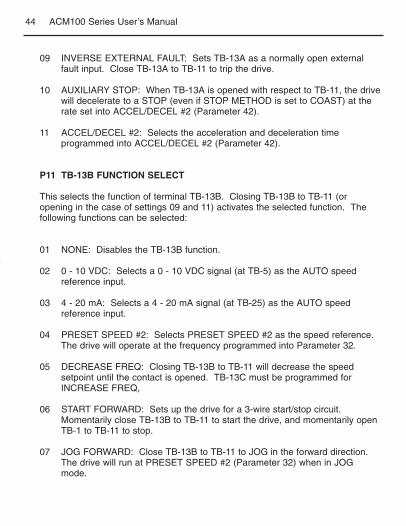
09 INVERSE EXTERNAL FAULT: Sets TB-13A as a normally open externalfault input. Close TB-13A to TB-11 to trip the drive.
10 AUXILIARY STOP: When TB-13A is opened with respect to TB-11, the drivewill decelerate to a STOP (even if STOP METHOD is set to COAST) at therate set into ACCEL/DECEL #2 (Parameter 42).
11 ACCEL/DECEL #2: Selects the acceleration and deceleration timeprogrammed into ACCEL/DECEL #2 (Parameter 42).
P11 TB-13B FUNCTION SELECT
This selects the function of terminal TB-13B. Closing TB-13B to TB-11 (oropening in the case of settings 09 and 11) activates the selected function. Thefollowing functions can be selected:
01 NONE: Disables the TB-13B function.
02 0 - 10 VDC: Selects a 0 - 10 VDC signal (at TB-5) as the AUTO speedreference input.
03 4 - 20 mA: Selects a 4 - 20 mA signal (at TB-25) as the AUTO speedreference input.
04 PRESET SPEED #2: Selects PRESET SPEED #2 as the speed reference.The drive will operate at the frequency programmed into Parameter 32.
05 DECREASE FREQ: Closing TB-13B to TB-11 will decrease the speedsetpoint until the contact is opened. TB-13C must be programmed forINCREASE FREQ,
06 START FORWARD: Sets up the drive for a 3-wire start/stop circuit.Momentarily close TB-13B to TB-11 to start the drive, and momentarily openTB-1 to TB-11 to stop.
07 JOG FORWARD: Close TB-13B to TB-11 to JOG in the forward direction.The drive will run at PRESET SPEED #2 (Parameter 32) when in JOGmode.

45ACM100 Series User’s Manual
08 JOG REVERSE: Close TB-13B to TB-11 to JOG in the reverse direction.The drive will run at PRESET SPEED #2 (Parameter 32) when in JOGmode.
WARNING! When operating in JOG mode, the STOP signal and the AUXILIARYSTOP function (see Parameters 10-12) WILL NOT stop the drive. To stop thedrive, remove the JOG command.
JOG REVERSE will operate the drive in reverse rotation even if ROTATIONDIRECTION (Parameter 17) is set to FORWARD ONLY.
09 EXTERNAL FAULT: Sets TB-13B as a normally closed external fault input.Open TB-13B to TB-11 to trip the drive.
10 INVERSE EXTERNAL FAULT: Sets TB-13 B as a normally open externalfault input. Close TB-13B to TB-11 to trip the drive.
11 AUXILIARY STOP: When TB-13B is opened with respect to TB-11, the drivewill decelerate to a STOP (even if STOP METHOD is set to COAST) at therate set into ACCEL/DECEL #2 (Parameter 42).
12 ACCEL/DECEL #2: Selects the acceleration and deceleration timeprogrammed into Parameter 42 - ACCEL/DECEL #2.
13 REMOTE KEYPAD: When the Remote Keypad option is being used, TB-13B must be set to this function. Also, TB-13E (Parameter 12) must be setfor REMOTE KEYPAD (21), and CONTROL (Parameter 14) must be set toREMOTE KEYPAD ONLY (02).
NOTE 1: If the drive is commanded to JOG while running, the drive will enterJOG mode and run at PRESET SPEED #2 (Parameter 32). When the JOGcommand is removed, the drive will STOP.
P12 TB-13E FUNCTION SELECT
This selects the function of terminal TB-13E. This terminal can be configured as adigital input (settings 01 to 10) or a digital status output (settings 11 to 20). Whenused as an input, closing TB-13E to TB-11 (or opening in the case of settings 07and 09) activates the selected function.

46 ACM100 Series User’s Manual
When used as an output, it can provide the drive’s status for monitoring. If theRemote Keypad option is being used, this parameter must be set to REMOTEKEYPAD (21).
The following input functions can be selected:
01 NONE: Disables the TB-13E function.
02 0 - 10 VDC: Selects a 0 - 10 VDC signal (at TB-5) as the AUTO speedreference input.
03 4 - 20 mA: Selects a 4 - 20 mA signal (at TB-25) as the AUTO speedreference input.
04 PRESET SPEED #3: Selects PRESET SPEED #3 as the speed reference.The drive will operate at the frequency programmed into Parameter 33.
05 INCREASE FREQ: Closing TB-13E to TB-11 will increase the speedsetpoint until the contact is opened. INCREASE FREQ will only work whenthe drive is running. TB-13B must be programmed for DECREASE FREQ.
06 START FORWARD: Sets up the drive for a 3-wire start/stop circuit.Momentarily close TB-13E to TB-11 to start the drive, and momentarily openTB-1 to TB-11 to stop.
07 EXTERNAL FAULT: Sets TB-13E as normally closed fault input. Close TB-13E to TB-11 to trip the drive.
08 INVERSE EXTERNAL FAULT: Sets TB-13E as a normally open externalfault input. Close TB-13E to TB-11 to trip the drive.
09 AUXILIARY STOP: When TB-13E is opened with respect to TB-11, the drivewill decelerate to a STOP (even if STOP METHOD is set to COAST) at therate set into ACCEL/DECEL #2 (Parameter 42).
10 ACCEL/DECEL #2: Selects the acceleration and deceleration timeprogrammed into ACCEL/DECEL #2 (Parameter 42).
The following output functions can be selected. The terms “open” and “close”refer to the state of the internal transistor that activates the circuit. When thetransistor is “closed” the circuit is complete, and TB-13E is pulled up to 15 VDC(when “open”, TB-13E is at 0 VDC potential).

47ACM100 Series User’s Manual
11 RUN: Closes upon a START command. Opens if the drive is in a STOPstate, the drive faults, or input power is removed. DC braking is considereda STOP state.
12 FAULT: Closes if there is no fault condition. Opens if the drive faults, orinput power is removed.
13 INVERSE FAULT: Closes if the drive faults. Opens if there is no faultcondition.
14 FAULT LOCKOUT: Closes when input power is applied. Opens if threerestart attempts are unsuccessful, or if input power is removed.
15 AT SET SPEED: Closes if the drive is within +0.5 Hz of the speed setpoint.
16 ABOVE PRESET SPEED #3: Closes if the output frequency exceedsPRESET SPEED #3 (Parameter 33). Opens if the output frequency is equalto or less than PRESET SPEED #3.
17 CURRENT LIMIT: Closes if the output current exceeds the CURRENT LIMITsetting. Opens if the output current is equal to or less than CURRENT LIMIT(see Parameter 25).
18 AUTOMATIC SPEED MODE: closes if an AUTOMATIC (terminal strip)speed reference is active. Opens if a STANDARD (Parameter 5) speedreference is active.
19 REVERSE: Closes when reverse rotation is active. Opens when forwardrotation is active (see Parameter 17 - ROTATION DIRECTION).
20 DYNAMIC BRAKING: TB-13E becomes the “trigger” that activates theoptional external Dynamic Braking module. Refer to the instructions includedwith the Dynamic Braking option.
21 REMOTE KEYPAD: When the Remote Keypad option is being used, TB-13E must be set for this function. Also, TB-13B (Parameter 11) must be setfor Remote Keypad (13) and CONTROL (Parameter 14) must be set forREMOTE KEYPAD ONLY (02).
48 ACM100 Series User’s Manual
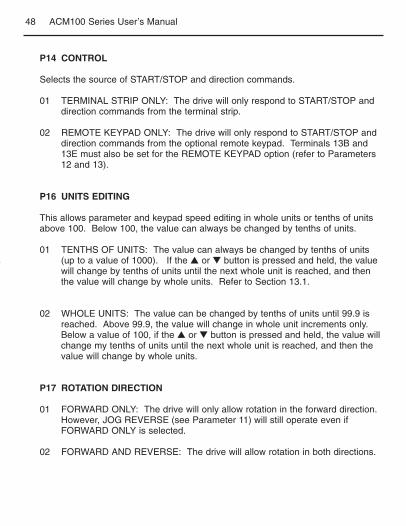
P14 CONTROL
Selects the source of START/STOP and direction commands.
01 TERMINAL STRIP ONLY: The drive will only respond to START/STOP anddirection commands from the terminal strip.
02 REMOTE KEYPAD ONLY: The drive will only respond to START/STOP anddirection commands from the optional remote keypad. Terminals 13B and13E must also be set for the REMOTE KEYPAD option (refer to Parameters12 and 13).
P16 UNITS EDITING
This allows parameter and keypad speed editing in whole units or tenths of unitsabove 100. Below 100, the value can always be changed by tenths of units.
01 TENTHS OF UNITS: The value can always be changed by tenths of units(up to a value of 1000). If the or button is pressed and held, the valuewill change by tenths of units until the next whole unit is reached, and thenthe value will change by whole units. Refer to Section 13.1.
02 WHOLE UNITS: The value can be changed by tenths of units until 99.9 isreached. Above 99.9, the value will change in whole unit increments only.Below a value of 100, if the or button is pressed and held, the value willchange my tenths of units until the next whole unit is reached, and then thevalue will change by whole units.
P17 ROTATION DIRECTION
01 FORWARD ONLY: The drive will only allow rotation in the forward direction.However, JOG REVERSE (see Parameter 11) will still operate even ifFORWARD ONLY is selected.
02 FORWARD AND REVERSE: The drive will allow rotation in both directions.

49ACM100 Series User’s Manual
P19 ACCELERATION TIME
This sets the acceleration rate for all of the speed reference sources (keypad,speed pot, jog, MOP, and preset speeds). This setting is the time to acceleratefrom 0 Hz to the BASE FREQUENCY (Parameter 27).
P20 DECELERATION TIME
This sets the deceleration rate for all of the speed reference sources (keypad,speed pot, jog, MOP, and preset speeds). This setting is the time to deceleratefrom BASE FREQUENCY to 0 Hz. If the drive is set for COAST TO STOP(setting 01 or 02 in Parameter 04), this parameter will have no effect when aSTOP command is given.
P21 DC BRAKE TIME
This sets the length of time that the DC braking voltage is applied to the motor.The DC BRAKE TIME should be set to the lowest value that provides satisfactoryoperation in order to minimize motor heating.
P22 DC BRAKE VOLTAGE
This sets the magnitude of the DC braking voltage, in percentage of the linevoltage. The point at which the DC braking is activated depends on the selectedSTOP METHOD (Parameter 04):
If COAST WITH DC BRAKE is selected, braking is activated after a time delay ofup to 2 seconds, depending on the output frequency at the time of the STOPcommand. In this case, the DC braking is the only force acting to decelerate theload.
If RAMP WITH DC BRAKE is selected, braking is activated when the outputfrequency reaches 0.2 Hz. In this case, the drive decelerates the load to a nearstop and then DC braking is used to bring the load to a final stop.
P23 MINIMUM FREQUENCY
This sets the minimum output frequency of the drive for all speed reference sourcesexcept the PRESET SPEEDS (Parameters 31-37), and is used with MAXIMUMFREQUENCY (Parameter 24) to define the operating range of the drive.

50 ACM100 Series User’s Manual
When using an analog input speed reference (0-10 VDC or 4-20 mA), Parameters45 and 46 (SPEED AT MIN SIGNAL and SPEED AT MAX SIGNAL) also affect thedrive’s speed range.
NOTE: If this parameter is changed while the drive is running, the new value willnot take effect until the drive is stopped.
P24 MAXIMUM FREQUENCY
This sets the maximum output frequency of the drive for all speed referencesources, and is used with MINIMUM FREQUENCY (Parameter 23) to define theoperating range of the drive.
When using an analog input speed reference (0-10 VDC or 4-20 mA), Parameters45 and 46 (SPEED AT MIN SIGNAL and SPEED AT MAX SIGNAL) also affect thedrive’s speed range.
NOTE: If this parameter is changed while the drive is running, the new value willnot take effect until the drive is stopped.
P25 CURRENT LIMIT
This sets the maximum allowable output current of the drive. The maximumsetting is either 180% or 150%, depending on whether LINE VOLTAGESELECTION (Parameter 01) is set to HIGH or LOW.
If the load demands more current than the CURRENT LIMIT setting, the drive willreduce the output frequency in an attempt to reduce the output current. When theovercurrent condition passes the drive will accelerate the motor back up to thespeed setpoint.
P26 MOTOR OVERLOAD
The ACM100 Series is UL approved for solid state motor overload protection, andtherefore does not require a separate thermal overload relay for single motorapplications. The drive contains an adjustable thermal overload circuit thatprotects the motor from excessive overcurrent. This circuit allows the drive todeliver up to 150% current for one minute. If the overload circuit “times out”, thedrive will trip into an OVERLOAD fault (displayed as “PF”).

51ACM100 Series User’s Manual
P27 BASE FREQUENCY
The BASE FREQUENCY determines the V/Hz ratio by setting the outputfrequency at which the drive will output full voltage to the motor. In most cases,the BASE FREQUENCY should be set to match the motor’s rated frequency.
Example: A 230 VAC, 60 Hz motor requires a V/Hz ratio of 3.83 (230V/60Hz =3.83 V/Hz) to produce full torque. Setting the BASE FREQUENCY to 60 Hzcauses the drive to output full voltage (230 VAC) at 60 Hz, which yields therequired 3.83 V/Hz. Output voltage is proportional to output frequency, so the3.83 V/Hz ratio is maintained from 0 - 60 Hz, allowing the motor to produce fulltorque from about 2 Hz (below 2 Hz there is less torque due to sip) up to 60 Hz.
NOTE: If this parameter is changed while the drive is running, the new value willnot take effect until the drive is stopped.
P28 FIXED BOOST
FIXED BOOST increases starting torque by increasing the output voltage whenoperating below half of the base frequency. For better out-of-the-boxperformance, ACM100 Series drives are shipped with a setting that is differentfrom the factory default of 1%. Units rated 0.33 to 1 HP (0.25 to 0.75 kW) are setto 5.3%, units rated 1.5 to 2 HP (1.1 to 1.5 kW) are set to 4.4%, 3 HP (2.2 kW)units are set to 3.6%, and 5 HP (4 kW) units are set to 3.0%.
P29 ACCELERATION BOOST
ACCELERATION BOOST helps accelerate high-inertia loads. During acceleration,the output voltage is increased to increase motor torque. Once the motor reachesthe new speed setpoint, the boost is turned off and the output voltage returns tothe normal value.
P30 SLIP COMPENSATION
SLIP COMPENSATION is used to counteract changes in motor speed (slip) caused bychanges in load. In a standard AC induction motor, the shaft speed decreases as loadincreases, and increases as load decreases. By increasing or decreasing the outputfrequency in response to an increasing or decreasing load, the slip is counteracted andspeed is maintained. Most standard NEMA B motors have a 3% slip rating.

52 ACM100 Series User’s Manual
P31-P37 PRESET SPEED #1 - #7
Preset speeds are activated by contact closures between TB-11 and TB-13A,13B, and 13E. The TB-13 terminals must be programmed as preset speedselects using Parameters 10-12.
NOTE 1: Preset speeds can operate below the frequency defined by theMinimum Frequency parameter (Parameter 23).
Refer to the table below for activation of the preset speeds using the TB-13terminals:
NOTE 2: When a TB-13 terminal is programmed for a function other than apreset speed select, it is considered OPEN for the table above.
Preset Speed #6 and #7 can also be used as skip frequencies to restrict the drivefrom operating at frequencies that cause vibration in the system. See Parameter38 below.
P38 SKIP BANDWIDTH
The ACM100 Series drive has two skip frequencies that can be used to lock outcritical frequencies that cause mechanical resonance in the system. Once SKIPBANDWIDTH is set to a value other than 0 Hz, the skip frequencies are enabled.When the skip frequency function is enabled, PRESET SPEED #6 and #7 areused as the skip frequencies. SKIP BANDWIDTH sets the range above the skipfrequencies that the drive will not operate within.
SPEED # TB-13A TB-13B TB-13E
1 CLOSED OPEN OPEN2 OPEN CLOSED OPEN3 OPEN OPEN CLOSED4 CLOSED CLOSED OPEN5 CLOSED OPEN CLOSED6 OPEN CLOSED CLOSED7 CLOSED CLOSED CLOSED
53ACM100 Series User’s Manual
Example: The critical frequency is 23 Hz, and it is desired to skip a frequencyrange of 3 Hz above and below the critical frequency (therefore the skip range is20 to 26 Hz). PRESET SPEED #6 or #7 would be set to 20 Hz, and the SKIPBANDWIDTH would be set to 6 Hz.
If the drive is running at a speed below the skip range, and it is given a speedcommand that is within the skip range, the drive will accelerate to the start of theskip range (20 Hz in the example) and run at that speed until the speed commandis greater than or equal to the “top” of the skip range. The drive will thenaccelerate through the ship range to the new speed. Likewise, if the drive isrunning at a speed above the skip range, and it is given a speed command that iswithin the skip range, the drive will decelerate to the “top” of the skip range (26 Hzin the example) and run at that speed until the speed command is less than orequal to the “bottom” of the skip range. The drive will then decelerate through theskip range to the new speed.
NOTE: PRESET SPEEDS #6 and #7 can still be used as preset speeds even ifthey are also being used as skip frequencies.
P39 SPEED SCALING
This scales the display to indicate speed in units other than frequency. Thisparameter should be set to the desired display value when the drive output is 60Hz. The highest setting is 6500, and the highest value that can be displayed is6553.6. If SPEED SCALING is set to 0.0, the speed scaling function is disabledand the display will indicate frequency.
Example: A machine produces 175 parts per hour when the motor is running at60 Hz. Setting SPEED SCALING to 175 will calibrate the drive’s display to read175 when the motor is running at 60 Hz. This is a linear function, so at 30 Hz thedisplay would read 87.5 Hz, and at 120 Hz the display would read 350.
NOTE 1: If the displayed value will exceed 999, the value is shown in two parts.For example, if the displayed value is 1800, the display will indicate this bytoggling between “1--” and “800”.

54 ACM100 Series User’s Manual
NOTE 2: If SPEED SCALING is set such that the maximum displayable value(6553.6 is exceeded, the display will flass “9999” to indicate that the value is outof range. For example, if SPEED SCALING is set to 6000, the drive will display6000 when it is running at 60 Hz. If the speed is increased past 65.5 Hz (at 65.5Hz, the scaled value would be 6550), the display will flash “9999” because ascaled value above 6553.6 cannot be displayed.
P42 ACCEL/DECEL #2
This parameter sets the second acceleration and deceleration rate of the drive, whichcan be activated using terminals TB-13A, 13B, or 13E (Parameter 10, 11, or 12).
P44 PASSWORD
This allows the PASSWORD to be changed to any number between 000 and 999.Setting PASSWORD to 000 disables the password function.
NOTE: The factory default password is 225.
P45 SPEED AT MIN SIGNAL
This sets the speed at which the drive will run when it receives the minimumspeed reference signal (10 VDC or 20 mA). This is used in conjunction withSPEED AT MAX SIGNAL (Parameter 46) to define the speed range of the drivewhen following an analog speed reference signal.
NOTE: If SPEED AT MIN SIGNAL is set higher than SPEED AT MAX SIGNAL,the drive will react inversely to the speed reference signal. Therefore, as thespeed reference signal increases, the drive speed will decrease, and vice-versa.
P46 SPEED AT MAX SIGNAL
This sets the speed at which the drive wil run when it receives the maximumspeed reference signal (10 VDC or 20 mA). This is used in conjunction withSPEED AT MIN SIGNAL (Parameter 45) to define the speed range of the drivewhen following an analog speed reference signal.

55ACM100 Series User’s Manual
NOTE: If SPEED AT MIN SIGNAL is set higher than SPEED AT MAX SIGNAL,the drive will react inversely to the speed reference signal. Therefore, as thespeed reference signal increases, the drive speed will decrease, and vice-versa.
P47 CLEAR FAULT HISTORY
01 MAINTAIN: Maintains the FAULT HISTORY (Parameter 50) entries fortroubleshooting.
02 CLEAR: Erases the FAULT HISTORY (Parameter 50) entries.
P48 PROGRAM SELECTION
This is used to select whether the drive will operate according to the user settingsor the optional OEM default settings, and to reset the parameters to defaultsettings. Refer to Section 13.2.
01 OPERATE WITH USER SETTINGS: The drive will operate according to theuser settings. Operation in USER mode allows the parameter values to bechanged to suit any application.
02 OPERATE WITH OEM DEFAULTS: The drive will operate according to theoptional OEM default settings, which configure the drive for a specificapplication. When operating in OEM mode, the parameter values can beviewed, but not changed. If an attempt is made to change a parametersetting, the display will flash “GE”. If the drive is not programmed with OEMdefault settings, the display will flash “GF” if this option is selected.
03 RESET OEM: Resets the user parameters to the OEM default settings. Ifthe drive is not programmed with OEM default settings, the dispaly will flash“GF” if this option is selected.
04 RESET 60: Resets the user parameters to the factory defaults for a 60 Hzbase frequency. Parameters 24, 27, and 46 will reset to 60.0 Hz.
05 RESET 50: Resets the user parameters to the factory defaults for a 50 Hzbase frequency. Parameters 24, 27, and 46 will reset to 50.0 Hz.

56 ACM100 Series User’s Manual
06 TRANSLATE: If an EPM from a drive with a previous (but compatible)parameter version is installed in a new drive, the new drive will function likethe previous version drive, but none of the parameter settings can bechanged (“cE” will be displayed if this is attempted). The TRANSLATEfunction converts the EPM to the new parameter version so that theparameters can be changed, but it also retains the old parameter settings sothe new drive will operate like the old drive without having to re-program allof the parameters Once the EPM is “translated”, it will no longer work in theold drive.
NOTE 1: If the user parameters are reset to the OEM defaults (using the RESETOEM option), and then OPERATE WITH USER SETTINGS is selected,the USER settings will be the same as the OEM default settings. Thisallows the drive to operate as if it was in OEM mode, but the parametervalues can be changed. This is useful if some of the OEM defaultsettings need to be fine-tuned for proper operation. The new parametervalues are not actually stored as new OEM default settings however;they are simply stored as new USER settings. Therefore, if theparameters are reset to the OEM defaults again, the parameters thatwere changed will be reset to their “old” value. The optional EPMProgrammer is required to change OEM default settings. Refer toSection 13.2.
NOTE 2: Only the TRANSLATE (06) function can be performed while the drive isrunning. The display will flash “Er” if an attempt is made to select anyother function while the drive is running.
P50 FAULT HISTORY
The FAULT HISTORY stores the last eight faults that tripped the drive. Refer toSection 16.0 - TROUBLESHOOTING for a list of the faults and possible causes.
Use the and buttons to scroll through the fault entries. The faults are storedfrom newest to oldest, with the first fault shown being the most recent.
The display will read “ _ _ “ if the FAULT HISTORY does not contain any faultmessages.

57ACM100 Series User’s Manual
P51 SOFTWARE VERSION
This displays the software version number for the control board software. Thisinformation is useful when contacting the factory for programming ortroublehsooting assistance.
The software version is displayed in two parts which alternate. The first part is thesoftware version, and the second part, is the revision number. For example, if thedisplay flashes “94” and “02”, this indicates that the drive contains the secondrevision of version 94 software.
P52 DC BUS VOLTAGE
This displays the DC bus voltage in percent of nominal. Nominal DC bus voltageis determined by multiplying the drive’s nameplate input voltage rating by 1.4.
P53 MOTOR VOLTAGE
This displays the output voltage in percent of the drive’s nameplate output voltagerating.
P54 MOTOR LOAD
This displays the motor load in percent of the drive’s output current rating.
P55 0-10 VDC INPUT
This displays the level of the 0-10 VDC input signal at TB-5. A reading of 100%indicates a 10 VDC input at TB-5.
P56 4-20 mA INPUT
This displays the level of the 4-20 mA input signal at TB-25. A reading of 20%indicates a 4 mA input at TB-25, and a reading of 100% indicates a 20 mA inputat TB-25.

58 ACM100 Series User’s Manual
P58 KEYPAD AND PROTECTION STATUS
This indicates the status of the buttons on the keypad, and the status of theprotective circuitry in the drive, using the horizontal segments of the LED. Anilluminated segment indicates that the corresponding button is pressed, or theprotective circuit is active. See the diagram below:
NOTE: FCLIM is an abbreviation for Fast Current Limit.
Mode
FCLIM
OUTPUTFAULT
TB-13ATB-1
TB-13B
TB-13E(input)
TB-13E(output)
FACTORYRESERVED
P57 TERMINAL STRIP STATUS
This indicates the status of several terminals using the vertical segments of theLED display. An illuminated segment indicates that the particular terminal isclosed to TB-11. See the diagram below:

59ACM100 Series User’s Manual
To aid in troubleshooting, Parameters 50 through 60 can be accessed withoutentering the PASSWORD. Simply press the Mode button twice to “skip” over thePASSWORD prompt, and “P50” will be displayed to indicate that the parametermenu has been entered and Parameter 50 (FAULT HISTORY) can be viewed.The and buttons can then be used to scroll from Parameter 50 to Parameter60. Once the desired parameter is found, press the Mode button to view its“contents”. When finished, press Mode to exit the parameter menu. An exampleis shown below:
In the example above, Parameter 54 - MOTOR LOAD is being viewed. The “77”in the example indicates that the load on the motor is 77% of the output currentrating of the drive.
16.0 TROUBLESHOOTING
Press Mode once
Display reads "00"
Upper right decimal point blinks
Press Mode again
Display reads "P50" (FAULT HISTORY)
Press Mode to view parameter contents
(77 = 77% LOAD)
Upper right decimal point blinks
Press Mode again to exit
Use and to scroll to the desired
parameter number
(In this example Parameter 54 has been
selected, which is MOTOR LOAD)

60 ACM100 Series User’s Manual
To clear a fault, issue a STOP command on the terminal strip. The fault will only clear if thecondition that caused the fault has passed. For example, if the drive trips on a LOW DC BUSVOLTAGE FAULT (LF) due to low input voltage, the fault cannot be cleared until the input voltagereturns to a normal level.
If the drive is programmed to automatically restart after a fault (see Parameter 03), the drive willattempt to restart three times after a fault (the drive will not restart after CF, cF, GF, FC, F1, F2-F9,or Fo faults). If all three restart attempts are unsuccessful, the drive will trip into FAULT LOCKOUT(LC), which requires a manual reset as described above.
The table below lists the fault conditions that will cause the drive to shut down, as well as somepossible causes. Please contact the factory for more information on troubleshooting faults.
FAULT MESSAGES
FAULT DESCRIPTION & POSSIBLE CAUSES
AF High Temp. Fault: Ambient temperature is too high; Cooling fan has failed (if equipped).
CF Control Fault: A blank EPM, or an EPM with corrupted data has been installed. Performa factory reset using Parameter 48 - PROGRAM SELECTION.
cF Incompatibility Fault: An EPM with an incompatible parameter version has been installed.Either remove the EPM or perform a factory reset (Parameter 48) to change theparameter version of the EPM to match the parameter version of the drive.
dF Dynamic Braking Fault: The drive has sensed that the dynamic braking resistors areoverheating and shuts down to protect the resistors.
EF External Fault: One of the TB-13 terminals is set as an External Fault input and thatterminal is open with respect to TB-11. Refer to Parameters 10, 11, and 12.
GF Data Fault: User data and OEM defaults in the EPM are corrupted.
HF High DC Bus Voltage Fault: Line voltage is too high; Deceleration rate is too fast; Over-hauling load. For fast deceleration or overhauling loads, dynamic braking may berequired.
JF Remote Keypad Fault: The communication link between the drive and the optionalRemote Keypad has been lost. Check for proper wiring and/or noise.
LF Low DC Bus Voltage Fault: Line voltage is too low.
OF Output Transistor Fault: Phase to Phase or phase to ground short circuit on the output;Boost settings are too high; Acceleration rate is too fast; Failed output transistor.
PF Current Overload Fault: VFD is undersized for the application; Mechanical problem withthe driven equipment.
UF Start Fault: Start command was present when the drive was powered up. Must wait 2seconds after power-up to apply Start command if START METHOD is set to NORMAL.
F1 EPM Fault: The EPM is missing or damaged.
FC, F2-F9, F0 Internal Faults: The control board has sensed a problem - consult factory.
61ACM100 Series User’s Manual
The following describes the various displays and messages that can appear onthe ACM100 drive.
17.1 SPEED DISPLAY
If the drive is in a STOP state (indicated by “- - - “ on the display), and thecommanded speed is changed, the display will show the commanded speed, andthe upper left decimal point will turn on solid. About five seconds after a changeis made, the display will begin to alternate between the commanded speed valueand the “- - -” display. If the Mode button is pressed, the display will stopalternating and show the “- - -” display only.
When the drive is given a START command, the displayed speed will startincreasing as the drive accelerates up to the commanded speed. If thecommanded speed is changed while the drive is running, the display will show thecommanded speed rather than the actual speed, until the actual speed reachesthe commanded speed.
If the commanded speed is changed faster than the drive can accelerate ordecelerate, the upper left decimal point will blink to indicate that the drive isaccelerating or decelerating to the new speed. Once the actual speed reachesthe commanded speed, the upper left decimal point will turn on solid for 5seconds and then turn off to indicate that the commanded speed has beenreached, and that the display is now showing the actual speed.
17.2 CHANGING THE SPEED REFERENCE SOURCE
When the speed source is changed while the drive is running, the display will flashthe message for the new speed source to indicate that the new speed source isactive. Also, if the drive is being controlled from a speed source other than the and buttons (0 - 10 VDC, 4 - 20 mA, etc.), and one of the or buttons ispressed, the display will flash the present speed source message to indicate thatthe and buttons are invalid.
17.0 ACM100 DISPLAY MESSAGES
62 ACM100 Series User’s Manual
Example 1: The drive is running and the present speed source is the keypad.TB-13A is programmed to select a 4-20 mA signal as the speed source. WhenTB-13A is closed to TB-11, the display will flash “EI” to indicate that the speedsource has changed to the 4-20 mA signal. If the contact between TB-13A andTB-11 is opened, the display will flash “CP” to indicate that the speed source haschanged back to the and buttons.
Example 2: The speed source is a 0 - 10 VDC signal. If the s or t button ispushed, the display will flash “EU” to indicate that the present speed source is the0 - 10 VDC signal and that the and buttons are invalid
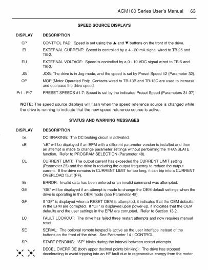
63ACM100 Series User’s Manual
SPEED SOURCE DISPLAYS
DISPLAY DESCRIPTION
CP CONTROL PAD: Speed is set using the and buttons on the front of the drive.
EI EXTERNAL CURRENT: Speed is controlled by a 4 - 20 mA signal wired to TB-25 andTB-2.
EU EXTERNAL VOLTAGE: Speed is controlled by a 0 - 10 VDC signal wired to TB-5 andTB-2.
JG JOG: The drive is in Jog mode, and the speed is set by Preset Speed #2 (Parameter 32).
OP MOP (Motor Operated Pot): Contacts wired to TB-13B and TB-13C are used to increaseand decrease the drive speed.
Pr1 - Pr7 PRESET SPEEDS #1-7: Speed is set by the indicated Preset Speed (Parameters 31-37).
STATUS AND WARNING MESSAGES
DISPLAY DESCRIPTION
br DC BRAKING: The DC braking circuit is activated.
cE “cE” will be displayed if an EPM with a different parameter version is installed and thenan attempt is made to change parameter settings without performing the TRANSLATEfunction. Refer to PROGRAM SELECTION (Parameter 48).
CL CURRENT LIMIT: The output current has exceeded the CURRENT LIMIT setting(Parameter 25) and the drive is reducing the output frequency to reduce the outputcurrent. If the drive remains in CURRENT LIMIT for too long, it can trip into a CURRENTOVERLOAD fault (PF).
Er ERROR: Invalid data has been entered or an invalid command was attempted.
GE “GE” will be displayed if an attempt is made to change the OEM default settings when thedrive is operating in the OEM mode (see Parameter 48).
GF If “GF” is displayed when a RESET OEM is attempted, it indicates that the OEM defaultsin the EPM are corrupted. If “GF” is displayed upon power-up, it indicates that the OEMdefaults and the user settings in the EPM are corrupted. Refer to Section 13.2.
LC FAULT LOCKOUT: The drive has failed three restart attempts and now requires manualreset.
SE SERIAL: The optional remote keypad is active as the user interface instead of thebuttons on the front of the drive. See Parameter 14 - CONTROL.
SP START PENDING: “SP” blinks during the interval between restart attempts.
DECEL OVERRIDE (both upper decimal points blinking): The drive has stoppeddecelerating to avoid tripping into an HF fault due to regenerative energy from the motor.
NOTE: The speed source displays will flash when the speed reference source is changed whilethe drive is running to indicate that the new speed reference source is active.

64 ACM100 Series User’s Manual
NOTES

65ACM100 Series User’s Manual
EC DECLARATION OF CONFORMITYIn accordance with EN45014:1998
Applied Council Directive(s): EMC Directive 89/336/EEC, as amended: 92/31/EECand 93/68/EEC, and Low Voltage Directive 73/23/EEC, as amended: 93/68/EEC
We, Authorized Representative:Minarik Corporation901 E. Thompson AvenueGlendale, CA 91201 U.S.A.
declare under our sole responsibility that the products to which this Declarationrelates, are in conformity with the relevant provisions of the following standards,provided that installations are carried out in accordance with manufacturer’sinstructions.
PRODUCTS RELATED TO DECLARATION
ACM110S-0.25 ACM110S-0.4 ACM110S-0.75 ACM110S-1.1ACM112S-0.25 ACM112S-0.4 ACM112S-0.55 ACM112S-0.75ACM112S-1.1 ACM112S-1.5 ACM112S-2.2 ACM112T-0.4ACM112T-0.75 ACM112T-1.1 ACM112T-1.5 ACM112T-2.2ACM112T-3.7 ACM114T-0.4 ACM114T-0.75 ACM114T-1.1ACM114T-1.5 ACM114T-2.2 ACM114T-3.7
RELEVANT EUROPEAN STANDARDS
EN 61800-3* - Adjustable speed electrical power drive systems, Part 3 - EMC productstandard, including specific test methods
EN 50178 - Electronic equipment for use in power installations.* with suitable line filters that are properly installed.
YEAR OF CE Marking (Low Voltage Directive): 2001
Signature:
Jim Reinwald, Compliance Manager
Date: 1 October 2001

901 E. Thompson Avenue, Glendale CA 91201-2011Sales: 800-646-2745, FAX: 800-394-6334
www.minarikcorp.com Document Number: 250-0362, Rev. 0Printed in the U.S.A – January 2003
SM13A