Embed Size (px)
DESCRIPTION
Manual
Citation preview
AcomHardware Installation and Maintenance
025-9574E
©2009 Zetron, Inc. All rights reserved. This publication is protected by copyright; information in this document is subject to change without notice. Zetron and the Zetron logo are registered trademarks of Zetron, Inc. Other company names and product names may be trademarks or registered trademarks of their respective owners. This publication may not be reproduced, translated, or altered, in whole or in part, without prior written consent from Zetron, Inc.
Software License
The Zetron software described in this manual is subject to the terms and conditions of Zetron's Software License Agreement, a copy of which is contained on the product distribution media or otherwise provided or presented to buyer. Installation and/or use of the Zetron software constitutes acceptance of Zetron's Software License Agreement.
Limited Warranty
Buyer assumes responsibility for the selection of the Products and Services to achieve buyer's or its customer's intended results and for the results obtained from the Products and Services. If buyer has provided Zetron with any requirements, specifications or drawings, or if Zetron provides buyer with such materials, such materials are provided solely for buyer's convenience and shall not be binding on Zetron unless agreed contractually by Zetron. UNLESS AGREED CONTRACTUALLY BY ZETRON, ZETRON DOES NOT WARRANT THAT THE PRODUCTS OR SERVICES WILL MEET BUYER'S OR ITS CUSTOMER'S REQUIREMENTS OR SPECIFICATIONS OR THAT OPERATION OF THE PRODUCTS WILL BE UNINTERRUPTED OR ERROR FREE. SUBJECT TO THE LIMITATIONS SET FORTH BELOW, Zetron warrants that all Zetron Products and Services will be free from material defects in material and workmanship for one year from date of shipment or performance of the Services (except where indicated otherwise in the Zetron Price Book). For buyer's convenience, Zetron may purchase and supply additional items manufactured by others. In these cases, although Zetron's warranty does not apply, buyer shall be the beneficiary of any applicable third party manufacturer's warranties, subject to the limitations therein. Zetron's warranty covers parts and Zetron factory labor. Buyer must provide written notice to Zetron within the warranty period of any defect. If the defect is not the result of improper or excessive use, or improper service, maintenance or installation, and if the Zetron Products or Zetron Accessories have not been otherwise damaged or modified after shipment, AS ZETRON'S SOLE AND EXCLUSIVE LIABILITY AND BUYER'S SOLE AND EXCLUSIVE REMEDY, Zetron shall either replace or repair the defective parts, replace the Zetron Products or Zetron Accessories, reperform the Services or refund the purchase price, at Zetron's option, after return of such items by buyer to Zetron. Shipment shall be paid for by the buyer. No credit shall be allowed for work performed by the buyer. Zetron Products or Zetron Accessories which are not defective shall be returned at buyer's expense, and testing and handling expense shall be borne by buyer. Out-of-warranty repairs will be invoiced at the then - current Zetron hourly rate plus the cost of needed components. THE FOREGOING WARRANTY AND THE THIRD PARTY MANUFACTURER'S WARRANTIES, IF ANY, ARE IN LIEU OF ANY AND ALL OTHER WARRANTIES EXPRESSED, IMPLIED OR ARISING UNDER LAW, INCLUDING, BUT NOT LIMITED TO, THE IMPLIED WARRANTIES OF MERCHANTABILITY, NON-INFRINGEMENT AND FITNESS FOR A PARTICULAR PURPOSE.
Limitation of Liability
Zetron makes no representation with respect to the contents of this document and/or the contents, performance, and function of any accompanying software.Further, Zetron reserves the right to revise this document or the accompanying software and to make changes in it from time to time without obligation to notify any person or organization of such revisions or changes.This document and any accompanying software are provided “As Is.” ZETRON SHALL NOT UNDER ANY CIRCUMSTANCES BE LIABLE TO BUYER OR ANY THIRD PARTY FOR ANY INCIDENTAL, SPECIAL, CONSEQUENTIAL OR INDIRECT LOSS OR DAMAGE ARISING OUT OF OR CONNECTED WITH BUYER'S PURCHASE OR USE OF ZETRON PRODUCTS, ZETRON ACCESSORIES OR ZETRON SERVICES. IN NO EVENT SHALL ZETRON'S LIABILITY (WHETHER FOR NEGLIGENCE OR OTHER TORT, IN CONTRACT OR OTHERWISE) EXCEED THE PRICE PAID TO ZETRON FOR THE ZETRON PRODUCTS, ZETRON ACCESSORIES OR ZETRON SERVICES.IP networks by their nature are subject to a number of limitations, such as security, reliability, and performance. Anyone using non-dedicated IP networks, such as shared WANs or the Internet, to connect to any Zetron Products or systems should consider and is responsible for these limitations.
3
Compliance Statements
This equipment has been tested and found to comply with the limits for a Class A digital device, pursuant to Part 15 of the FCC Rules. These limits are designed to provide reasonable protection against harmful interference when the equipment is operated in a commercial environment. This equipment generates, uses, and can radiate radio frequency energy and, if not installed and used in accordance with the instruction manual, may cause harmful interference to radio communications. Operation of this equipment in a residential area is likely to cause harmful interference in which case the user will be required to correct the interference at his own expense.The Ringer Equivalence Number (REN) for this terminal equipment is 0.1. The REN assigned to each terminal equipment provides an indication of the maximum number of terminals allowed to be connected to a telephone interface. The termination on an interface may consist of any combination of devices subject only to the requirement that the sum of the RENs of all the devices does not exceed 5.0.
Safety Summary
• Follow all warnings and instructions marked on the equipment or included in documentation.• Only technically qualified service personnel are permitted to install or service the equipment.• Be aware of and avoid contact with areas subject to high voltage or amperage. Because some components can store
dangerous charges even after power is disconnected, always discharge components before touching.• Never insert objects of any kind through openings in the equipment. Conductive foreign objects could produce a short
circuit that could cause fire, electrical shock, or equipment damage.• Remove rings, watches, and other metallic objects from your body before opening equipment. These could be
electrical shock or burn hazards.• Ensure that a proper electrostatic discharge device is used, to prevent damage to electronic components.• Do not attempt internal service of equipment unless another person, capable of rendering aid and resuscitation, is
present.• Do not work near rotating fans unless absolutely necessary. Exercise caution to prevent fans from taking in foreign
objects, including hair, clothing, and loose objects.• Use care when moving equipment, especially rack-mounted modules, which could become unstable. Certain items
may be heavy. Use proper care when lifting.
Warning! For your safety and the protection of the equipment, observe these precautions when installing or servicing Zetron equipment:
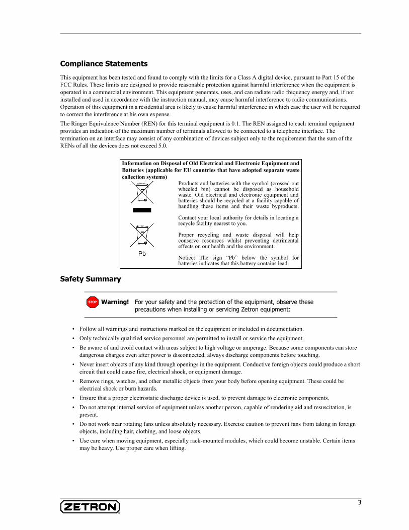
Products and batteries with the symbol (crossed-out wheeled bin) cannot be disposed as household waste. Old electrical and electronic equipment and batteries should be recycled at a facility capable of handling these items and their waste byproducts.
Contact your local authority for details in locating a recycle facility nearest to you.
Proper recycling and waste disposal will help conserve resources whilst preventing detrimental effects on our health and the environment.
Notice: The sign “Pb” below the symbol for batteries indicates that this battery contains lead.
Information on Disposal of Old Electrical and Electronic Equipment and Batteries (applicable for EU countries that have adopted separate waste collection systems)
STOP
4 025-9574E
Release History
Release Enhancements/Changes
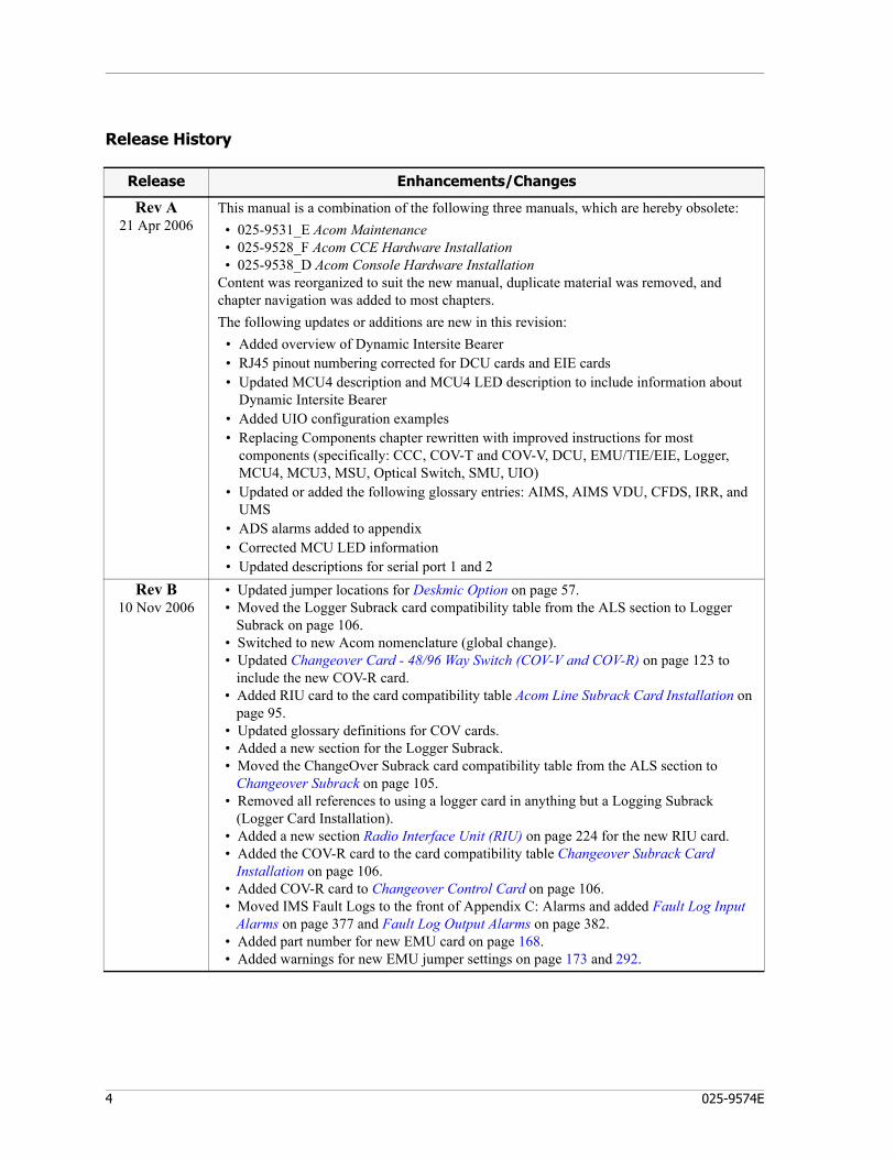
Rev A21 Apr 2006
This manual is a combination of the following three manuals, which are hereby obsolete: • 025-9531_E Acom Maintenance • 025-9528_F Acom CCE Hardware Installation • 025-9538_D Acom Console Hardware InstallationContent was reorganized to suit the new manual, duplicate material was removed, and chapter navigation was added to most chapters.The following updates or additions are new in this revision:
• Added overview of Dynamic Intersite Bearer• RJ45 pinout numbering corrected for DCU cards and EIE cards• Updated MCU4 description and MCU4 LED description to include information about
Dynamic Intersite Bearer• Added UIO configuration examples• Replacing Components chapter rewritten with improved instructions for most
components (specifically: CCC, COV-T and COV-V, DCU, EMU/TIE/EIE, Logger, MCU4, MCU3, MSU, Optical Switch, SMU, UIO)
• Updated or added the following glossary entries: AIMS, AIMS VDU, CFDS, IRR, and UMS
• ADS alarms added to appendix• Corrected MCU LED information• Updated descriptions for serial port 1 and 2
Rev B10 Nov 2006
• Updated jumper locations for Deskmic Option on page 57. • Moved the Logger Subrack card compatibility table from the ALS section to Logger
Subrack on page 106. • Switched to new Acom nomenclature (global change). • Updated Changeover Card - 48/96 Way Switch (COV-V and COV-R) on page 123 to
include the new COV-R card. • Added RIU card to the card compatibility table Acom Line Subrack Card Installation on
page 95. • Updated glossary definitions for COV cards. • Added a new section for the Logger Subrack. • Moved the ChangeOver Subrack card compatibility table from the ALS section to
Changeover Subrack on page 105. • Removed all references to using a logger card in anything but a Logging Subrack
(Logger Card Installation). • Added a new section Radio Interface Unit (RIU) on page 224 for the new RIU card. • Added the COV-R card to the card compatibility table Changeover Subrack Card
Installation on page 106. • Added COV-R card to Changeover Control Card on page 106. • Moved IMS Fault Logs to the front of Appendix C: Alarms and added Fault Log Input
Alarms on page 377 and Fault Log Output Alarms on page 382. • Added part number for new EMU card on page 168. • Added warnings for new EMU jumper settings on page 173 and 292.

5
Rev C31 Mar 2008
• Fixed Radio Interface Unit (RIU) on page 224 to reflect the correct name, improve the overview text, provide a warning about -48v lines, and correct JP29 in the jumper table.
• Updated MCU4 Status Indicator Functions (When used in an ADS, not as an Intersite Bearer) on page 188 to show new LED behavior based on the Standby Bearer.
• Fixed nomenclature: Changed “AIS” to “ALS”, whenever “AIS” referred to Acom hardware instead of an Alarm Indication Signal. Standardized on “4W E&M” to replace “4W VF” when referring to that ACU module. Changed “ACS.ini” to “AcomConsole.ini”
• Increased the maximum number of consoles and lines in Capacity on page 27.• Added OLCB and LLCB to Appendix A: Acom Glossary on page 347.• Updated Dual E1 Interface Module on page 86 to add twisted-pair E1 ACU module.• Removed the detailed SMU DSP information from Signaling Management Unit (SMU)
on page 240.• Consolidated detailed information about the ACU into the Acom Console Unit (ACU) on
page 73, and added extra specification information from the DCS-5020 manual.• Added the new section Model 3030 PSAP TDD on page 64.• Added the new section Capacity on page 27, which introduces the dynamic backbone
and related concepts.• Added the new section Channel TX and RX Wiring on page 233 to show how to wire
various radio types to the RIU.• Updated Digital Inputs on page 408 and Internal Link Error on page 409 to show that
they are configurable and to remove references to unsupported numbers of MCUs.• Updated Capacity of DS3 switches on page 103 to include additional resources and
updated capacity.Rev D
16 May 2008• Support for stereo headsets. Monitor Speaker 1 can be redirected to one side of the
headset. Associated new jackbox and cable. Page 44.• RIU card jumper settings corrected. Page 246.• Added Dual E1 Fiber Module section. Page 78.
Rev E6 Mar 2009
• Only operating systems supported are Windows Vista Business SP1 and Windows XP Professional SP3.
• Changed all terminal-related procedures to assume use of generic terminal software.• Updated DCU Interfaces on page 133 to mention RS-485 and external serial clock.• Added Protected Mode on page 373 to describe the new alarm mode.• Added Zetron Desktop Microphone on page 57.• Added MCU4 Status Indicator Functions (When used in an ADS as an Intersite Bearer)
on page 189.• Updated Appendix A: Acom Glossary on page 347.• Updated Acom Console Unit (ACU) on page 73 for new ACU with USB.• Updated Internal Link Error on page 409 and Internal Link Master on page 410 for
MCU configured as ISB.• Updated default passwords for ALS, ADS, and ACU.• Removed older, obsolete equipment (AIU, Optical Switch, Logger Card, Logger
Subrack, and generic desktop PC speaker).• Updated ISB information in the following sections: Intersite Bearers on page 25, Time
Slots on page 25, and Capacity on page 27.• Updated Zetron Speakers on page 54 with connection information.
Release Enhancements/Changes

6 025-9574E
Contents
7
Contents
Introduction. . . . . . . . . . . . . . . . . . . . . . . . . . . . . . . . . . . . . . . . . . . . . . . . . 19Documentation Set . . . . . . . . . . . . . . . . . . . . . . . . . . . . . . . . . . . . . . . . . . . . . . . . . . . . . 19
This Manual . . . . . . . . . . . . . . . . . . . . . . . . . . . . . . . . . . . . . . . . . . . . . . . . . . . . . . . 19Overview . . . . . . . . . . . . . . . . . . . . . . . . . . . . . . . . . . . . . . . . . . . . . . . . . . . . . . 19Installation Procedures . . . . . . . . . . . . . . . . . . . . . . . . . . . . . . . . . . . . . . . . . . . . . 19Hardware Reference. . . . . . . . . . . . . . . . . . . . . . . . . . . . . . . . . . . . . . . . . . . . . . . 19Maintenance Procedures. . . . . . . . . . . . . . . . . . . . . . . . . . . . . . . . . . . . . . . . . . . . 19
Associated Documents . . . . . . . . . . . . . . . . . . . . . . . . . . . . . . . . . . . . . . . . . . . . . . . . 20Acom System Overview . . . . . . . . . . . . . . . . . . . . . . . . . . . . . . . . . . . . . . . . . . . . . . . . . . 20
System Conceptual Diagrams . . . . . . . . . . . . . . . . . . . . . . . . . . . . . . . . . . . . . . . . . . . 20Console Hardware . . . . . . . . . . . . . . . . . . . . . . . . . . . . . . . . . . . . . . . . . . . . . . . . . . . 21
Console Hardware Requirements . . . . . . . . . . . . . . . . . . . . . . . . . . . . . . . . . . . . . . 22Electrical Requirements . . . . . . . . . . . . . . . . . . . . . . . . . . . . . . . . . . . . . . . . . . . . 23Connectors and pin-outs. . . . . . . . . . . . . . . . . . . . . . . . . . . . . . . . . . . . . . . . . . . . 23
Common Control Equipment (CCE) . . . . . . . . . . . . . . . . . . . . . . . . . . . . . . . . . . . . . . . 23DS3 Switches . . . . . . . . . . . . . . . . . . . . . . . . . . . . . . . . . . . . . . . . . . . . . . . . . . . . . . 24Intersite Bearers . . . . . . . . . . . . . . . . . . . . . . . . . . . . . . . . . . . . . . . . . . . . . . . . . . . . 25Time Slots. . . . . . . . . . . . . . . . . . . . . . . . . . . . . . . . . . . . . . . . . . . . . . . . . . . . . . . . . 25
Backbone Time Slots for Local Resources . . . . . . . . . . . . . . . . . . . . . . . . . . . . . . . . 25Bearer Time Slots for Intersite Resources . . . . . . . . . . . . . . . . . . . . . . . . . . . . . . . . 26
Capacity . . . . . . . . . . . . . . . . . . . . . . . . . . . . . . . . . . . . . . . . . . . . . . . . . . . . . . . . . . 27
Installation Preparation . . . . . . . . . . . . . . . . . . . . . . . . . . . . . . . . . . . . . . . 29General Preparation . . . . . . . . . . . . . . . . . . . . . . . . . . . . . . . . . . . . . . . . . . . . . . . . . . . . 30
Operating Environment . . . . . . . . . . . . . . . . . . . . . . . . . . . . . . . . . . . . . . . . . . . . . . . 30Safety. . . . . . . . . . . . . . . . . . . . . . . . . . . . . . . . . . . . . . . . . . . . . . . . . . . . . . . . . . . . 30
Antistatic Work Practice . . . . . . . . . . . . . . . . . . . . . . . . . . . . . . . . . . . . . . . . . . . . 31System Architecture . . . . . . . . . . . . . . . . . . . . . . . . . . . . . . . . . . . . . . . . . . . . . . . . . . 31As-Built Documentation . . . . . . . . . . . . . . . . . . . . . . . . . . . . . . . . . . . . . . . . . . . . . . . 32Recommended Installer Materials and Equipment . . . . . . . . . . . . . . . . . . . . . . . . . . . . . 33
Back Room (CCE) Preparations . . . . . . . . . . . . . . . . . . . . . . . . . . . . . . . . . . . . . . . . . . . . 33Testing of New/Existing Circuits. . . . . . . . . . . . . . . . . . . . . . . . . . . . . . . . . . . . . . . . . . 34Install Additional Power . . . . . . . . . . . . . . . . . . . . . . . . . . . . . . . . . . . . . . . . . . . . . . . 35Install Grounding System . . . . . . . . . . . . . . . . . . . . . . . . . . . . . . . . . . . . . . . . . . . . . . 36Install Cable Trays . . . . . . . . . . . . . . . . . . . . . . . . . . . . . . . . . . . . . . . . . . . . . . . . . . . 37Mount Acom Punchdown Blocks on Demarc Wall . . . . . . . . . . . . . . . . . . . . . . . . . . . . . 38Lightning Protection . . . . . . . . . . . . . . . . . . . . . . . . . . . . . . . . . . . . . . . . . . . . . . . . . . 38

Contents
8 025-9574E
Check Cabinet Route . . . . . . . . . . . . . . . . . . . . . . . . . . . . . . . . . . . . . . . . . . . . . . . . . . 39Environment . . . . . . . . . . . . . . . . . . . . . . . . . . . . . . . . . . . . . . . . . . . . . . . . . . . . . . . . 39
Front Room (Console) Preparations . . . . . . . . . . . . . . . . . . . . . . . . . . . . . . . . . . . . . . . . . . 40Console Loop Installation . . . . . . . . . . . . . . . . . . . . . . . . . . . . . . . . . . . . . . . . . . . . . . . 40
Twisted Pair Loops . . . . . . . . . . . . . . . . . . . . . . . . . . . . . . . . . . . . . . . . . . . . . . . . . 40Coax Loops . . . . . . . . . . . . . . . . . . . . . . . . . . . . . . . . . . . . . . . . . . . . . . . . . . . . . . 41Patch Panel . . . . . . . . . . . . . . . . . . . . . . . . . . . . . . . . . . . . . . . . . . . . . . . . . . . . . . 42
Console Network Installation . . . . . . . . . . . . . . . . . . . . . . . . . . . . . . . . . . . . . . . . . . . . 42Continuing the Installation . . . . . . . . . . . . . . . . . . . . . . . . . . . . . . . . . . . . . . . . . . . . . . 42
CCE Installation Procedures . . . . . . . . . . . . . . . . . . . . . . . . . . . . . . . . . . . 43CCE Installation . . . . . . . . . . . . . . . . . . . . . . . . . . . . . . . . . . . . . . . . . . . . . . . . . . . . . . . . 43
Maintenance Terminal . . . . . . . . . . . . . . . . . . . . . . . . . . . . . . . . . . . . . . . . . . . . . . . . . 46System Power Up and Reset . . . . . . . . . . . . . . . . . . . . . . . . . . . . . . . . . . . . . . . . . . . . . . . 46
System Power Up Sequence . . . . . . . . . . . . . . . . . . . . . . . . . . . . . . . . . . . . . . . . . . . . . 46Power Up Sequence . . . . . . . . . . . . . . . . . . . . . . . . . . . . . . . . . . . . . . . . . . . . . . . . 47
Restart . . . . . . . . . . . . . . . . . . . . . . . . . . . . . . . . . . . . . . . . . . . . . . . . . . . . . . . . . . . . 47Manual Reset . . . . . . . . . . . . . . . . . . . . . . . . . . . . . . . . . . . . . . . . . . . . . . . . . . . . 48
Continuing the Installation . . . . . . . . . . . . . . . . . . . . . . . . . . . . . . . . . . . . . . . . . . . . . . 48
Console Installation Procedures . . . . . . . . . . . . . . . . . . . . . . . . . . . . . . . . 49Acom Console Unit Installation . . . . . . . . . . . . . . . . . . . . . . . . . . . . . . . . . . . . . . . . . . . . . 49
Acom Console Unit Overview . . . . . . . . . . . . . . . . . . . . . . . . . . . . . . . . . . . . . . . . . . . . 50Installation . . . . . . . . . . . . . . . . . . . . . . . . . . . . . . . . . . . . . . . . . . . . . . . . . . . . . . 51
Headset Jackbox . . . . . . . . . . . . . . . . . . . . . . . . . . . . . . . . . . . . . . . . . . . . . . . . . . . . . 51Headset Jackbox with Volume Control . . . . . . . . . . . . . . . . . . . . . . . . . . . . . . . . . . . . . . 52Stereo Headset Jackbox without Volume Control. . . . . . . . . . . . . . . . . . . . . . . . . . . . . . . 52Telephone Radio Headset Interface . . . . . . . . . . . . . . . . . . . . . . . . . . . . . . . . . . . . . . . . 53Zetron Speakers . . . . . . . . . . . . . . . . . . . . . . . . . . . . . . . . . . . . . . . . . . . . . . . . . . . . . 54Configuring the Select and Monitor 1 Speakers for Acom . . . . . . . . . . . . . . . . . . . . . . . . . 55Configuring Monitor 2 and 3 Speakers for Acom . . . . . . . . . . . . . . . . . . . . . . . . . . . . . . . 56Deskmic Option . . . . . . . . . . . . . . . . . . . . . . . . . . . . . . . . . . . . . . . . . . . . . . . . . . . . . . 57
Zetron Desktop Microphone . . . . . . . . . . . . . . . . . . . . . . . . . . . . . . . . . . . . . . . . . . 57Legacy Desktop Microphone . . . . . . . . . . . . . . . . . . . . . . . . . . . . . . . . . . . . . . . . . . 57
Integrator IRR. . . . . . . . . . . . . . . . . . . . . . . . . . . . . . . . . . . . . . . . . . . . . . . . . . . . . . . 58Requirements . . . . . . . . . . . . . . . . . . . . . . . . . . . . . . . . . . . . . . . . . . . . . . . . . . . . 59Theory of Operation. . . . . . . . . . . . . . . . . . . . . . . . . . . . . . . . . . . . . . . . . . . . . . . . 59Software Control . . . . . . . . . . . . . . . . . . . . . . . . . . . . . . . . . . . . . . . . . . . . . . . . . . 59Contact Closure . . . . . . . . . . . . . . . . . . . . . . . . . . . . . . . . . . . . . . . . . . . . . . . . . . . 59VOX Recording . . . . . . . . . . . . . . . . . . . . . . . . . . . . . . . . . . . . . . . . . . . . . . . . . . . 60SoundBlaster Installation . . . . . . . . . . . . . . . . . . . . . . . . . . . . . . . . . . . . . . . . . . . . 60Hardware Installation . . . . . . . . . . . . . . . . . . . . . . . . . . . . . . . . . . . . . . . . . . . . . . . 61E&M 4-Wire Module Installation . . . . . . . . . . . . . . . . . . . . . . . . . . . . . . . . . . . . . . . 61Configuring Acom for Integrator IRR . . . . . . . . . . . . . . . . . . . . . . . . . . . . . . . . . . . . 61Integrator Software Installation. . . . . . . . . . . . . . . . . . . . . . . . . . . . . . . . . . . . . . . . 62Configuring Integrator IRR . . . . . . . . . . . . . . . . . . . . . . . . . . . . . . . . . . . . . . . . . . . 62Configure Acom Console to use IRR. . . . . . . . . . . . . . . . . . . . . . . . . . . . . . . . . . . . . 63
Model 3030 PSAP TDD . . . . . . . . . . . . . . . . . . . . . . . . . . . . . . . . . . . . . . . . . . . . . . . . . 64Other Interfaces . . . . . . . . . . . . . . . . . . . . . . . . . . . . . . . . . . . . . . . . . . . . . . . . . . . . . . . . 65
Operator Active Lamp . . . . . . . . . . . . . . . . . . . . . . . . . . . . . . . . . . . . . . . . . . . . . . . . . 65Overview . . . . . . . . . . . . . . . . . . . . . . . . . . . . . . . . . . . . . . . . . . . . . . . . . . . . . . . 65
9
Contents
Required Materials . . . . . . . . . . . . . . . . . . . . . . . . . . . . . . . . . . . . . . . . . . . . . . . . 65Assembling the Operator Active Lamp . . . . . . . . . . . . . . . . . . . . . . . . . . . . . . . . . . 66Position Installation . . . . . . . . . . . . . . . . . . . . . . . . . . . . . . . . . . . . . . . . . . . . . . . 67Acom Console Unit Modification. . . . . . . . . . . . . . . . . . . . . . . . . . . . . . . . . . . . . . . 67IMS ACU Configuration . . . . . . . . . . . . . . . . . . . . . . . . . . . . . . . . . . . . . . . . . . . . . 68AcomConsole.ini File Modification . . . . . . . . . . . . . . . . . . . . . . . . . . . . . . . . . . . . . 68
Foot Switch . . . . . . . . . . . . . . . . . . . . . . . . . . . . . . . . . . . . . . . . . . . . . . . . . . . . . . . . 69E1 Digital Interfaces. . . . . . . . . . . . . . . . . . . . . . . . . . . . . . . . . . . . . . . . . . . . . . . . . . 71
Console Quick Checkout Instructions . . . . . . . . . . . . . . . . . . . . . . . . . . . . . . . . . . . . . . . . 71
Hardware Components . . . . . . . . . . . . . . . . . . . . . . . . . . . . . . . . . . . . . . . . 73Acom Console Unit (ACU) . . . . . . . . . . . . . . . . . . . . . . . . . . . . . . . . . . . . . . . . . . . . . . . . 73
General. . . . . . . . . . . . . . . . . . . . . . . . . . . . . . . . . . . . . . . . . . . . . . . . . . . . . . . . . . . 73ACU Specifications . . . . . . . . . . . . . . . . . . . . . . . . . . . . . . . . . . . . . . . . . . . . . . . . . . . 74ACU Power Requirements . . . . . . . . . . . . . . . . . . . . . . . . . . . . . . . . . . . . . . . . . . . . . . 75ACU Internal Layout. . . . . . . . . . . . . . . . . . . . . . . . . . . . . . . . . . . . . . . . . . . . . . . . . . 76ACU Main Board Functions . . . . . . . . . . . . . . . . . . . . . . . . . . . . . . . . . . . . . . . . . . . . . 76ACU Hardware Connections . . . . . . . . . . . . . . . . . . . . . . . . . . . . . . . . . . . . . . . . . . . . 76ACU External Interfaces . . . . . . . . . . . . . . . . . . . . . . . . . . . . . . . . . . . . . . . . . . . . . . . 77ACU Main Board Connections . . . . . . . . . . . . . . . . . . . . . . . . . . . . . . . . . . . . . . . . . . . 78
Main Board COM Ports 1-4 . . . . . . . . . . . . . . . . . . . . . . . . . . . . . . . . . . . . . . . . . . 78Digital Input Interface . . . . . . . . . . . . . . . . . . . . . . . . . . . . . . . . . . . . . . . . . . . . . . . . 81
Electrical Specifications. . . . . . . . . . . . . . . . . . . . . . . . . . . . . . . . . . . . . . . . . . . . . 81Digital Output Interface . . . . . . . . . . . . . . . . . . . . . . . . . . . . . . . . . . . . . . . . . . . . . . . 82
Electrical Specifications. . . . . . . . . . . . . . . . . . . . . . . . . . . . . . . . . . . . . . . . . . . . . 82DSP Functions . . . . . . . . . . . . . . . . . . . . . . . . . . . . . . . . . . . . . . . . . . . . . . . . . . . . . . 83ACU Expansion Slots . . . . . . . . . . . . . . . . . . . . . . . . . . . . . . . . . . . . . . . . . . . . . . . . . 83Plug-In Modules. . . . . . . . . . . . . . . . . . . . . . . . . . . . . . . . . . . . . . . . . . . . . . . . . . . . . 84
Operator’s Audio Module. . . . . . . . . . . . . . . . . . . . . . . . . . . . . . . . . . . . . . . . . . . . 85Dual E1 Interface Module . . . . . . . . . . . . . . . . . . . . . . . . . . . . . . . . . . . . . . . . . . . 86Dual E1 Fiber Module . . . . . . . . . . . . . . . . . . . . . . . . . . . . . . . . . . . . . . . . . . . . . . 88Dual 4W E&M Module. . . . . . . . . . . . . . . . . . . . . . . . . . . . . . . . . . . . . . . . . . . . . . 89
Acom Line Subracks . . . . . . . . . . . . . . . . . . . . . . . . . . . . . . . . . . . . . . . . . . . . . . . . . . . . 92Subrack Mounting . . . . . . . . . . . . . . . . . . . . . . . . . . . . . . . . . . . . . . . . . . . . . . . . . . . 93General Circuit Card Installation . . . . . . . . . . . . . . . . . . . . . . . . . . . . . . . . . . . . . . . . . 94
Electrical Isolation . . . . . . . . . . . . . . . . . . . . . . . . . . . . . . . . . . . . . . . . . . . . . . . . 96Acom Line Subrack Grounding. . . . . . . . . . . . . . . . . . . . . . . . . . . . . . . . . . . . . . . . 97Signal Cable Connections . . . . . . . . . . . . . . . . . . . . . . . . . . . . . . . . . . . . . . . . . . . 99
Acom Line Subrack Specifications . . . . . . . . . . . . . . . . . . . . . . . . . . . . . . . . . . . . . . . . 100Power Connection . . . . . . . . . . . . . . . . . . . . . . . . . . . . . . . . . . . . . . . . . . . . . . . . 100Absolute Maximum Ratings . . . . . . . . . . . . . . . . . . . . . . . . . . . . . . . . . . . . . . . . . . 101
VoIP Acom Line Subrack. . . . . . . . . . . . . . . . . . . . . . . . . . . . . . . . . . . . . . . . . . . . . . . 101Cloning an Acom ALS . . . . . . . . . . . . . . . . . . . . . . . . . . . . . . . . . . . . . . . . . . . . . . . . . 102
Acom DS3 Switch (ADS) Subrack . . . . . . . . . . . . . . . . . . . . . . . . . . . . . . . . . . . . . . . . . . . 102Basic ADS Rack . . . . . . . . . . . . . . . . . . . . . . . . . . . . . . . . . . . . . . . . . . . . . . . . . . . . . 103Rack Configuration. . . . . . . . . . . . . . . . . . . . . . . . . . . . . . . . . . . . . . . . . . . . . . . . . . . 103General Circuit Card Installation . . . . . . . . . . . . . . . . . . . . . . . . . . . . . . . . . . . . . . . . . 104
Jumper Settings. . . . . . . . . . . . . . . . . . . . . . . . . . . . . . . . . . . . . . . . . . . . . . . . . . 105Combine Mode . . . . . . . . . . . . . . . . . . . . . . . . . . . . . . . . . . . . . . . . . . . . . . . . . . 105
Changeover Subrack . . . . . . . . . . . . . . . . . . . . . . . . . . . . . . . . . . . . . . . . . . . . . . . . . . . . 105Changeover Hardware . . . . . . . . . . . . . . . . . . . . . . . . . . . . . . . . . . . . . . . . . . . . . . . . 106
Changeover Subrack . . . . . . . . . . . . . . . . . . . . . . . . . . . . . . . . . . . . . . . . . . . . . . 106
Contents
10 025-9574E
Changeover Control Card . . . . . . . . . . . . . . . . . . . . . . . . . . . . . . . . . . . . . . . . . . . 106Additional Hardware. . . . . . . . . . . . . . . . . . . . . . . . . . . . . . . . . . . . . . . . . . . . . . . 107
Changeover Troubleshooting. . . . . . . . . . . . . . . . . . . . . . . . . . . . . . . . . . . . . . . . . . . . 108Additional Changeover Subracks . . . . . . . . . . . . . . . . . . . . . . . . . . . . . . . . . . . . . . . . . 108
Acom Card Reference . . . . . . . . . . . . . . . . . . . . . . . . . . . . . . . . . . . . . . . . 111Changeover Control Card (CCC) . . . . . . . . . . . . . . . . . . . . . . . . . . . . . . . . . . . . . . . . . . . . 112
CCC Block Diagram . . . . . . . . . . . . . . . . . . . . . . . . . . . . . . . . . . . . . . . . . . . . . . . . . . 113Description of Major Functional Blocks . . . . . . . . . . . . . . . . . . . . . . . . . . . . . . . . . . 113
CCC Interfaces . . . . . . . . . . . . . . . . . . . . . . . . . . . . . . . . . . . . . . . . . . . . . . . . . . . . . 114Front Edge Layout . . . . . . . . . . . . . . . . . . . . . . . . . . . . . . . . . . . . . . . . . . . . . . . . 114Physical Layout . . . . . . . . . . . . . . . . . . . . . . . . . . . . . . . . . . . . . . . . . . . . . . . . . . 115Rear Edge Layout . . . . . . . . . . . . . . . . . . . . . . . . . . . . . . . . . . . . . . . . . . . . . . . . 115LED Indicators. . . . . . . . . . . . . . . . . . . . . . . . . . . . . . . . . . . . . . . . . . . . . . . . . . . 115Reset . . . . . . . . . . . . . . . . . . . . . . . . . . . . . . . . . . . . . . . . . . . . . . . . . . . . . . . . . 115Settings . . . . . . . . . . . . . . . . . . . . . . . . . . . . . . . . . . . . . . . . . . . . . . . . . . . . . . . 115Connector Details . . . . . . . . . . . . . . . . . . . . . . . . . . . . . . . . . . . . . . . . . . . . . . . . 115
CCC Installation. . . . . . . . . . . . . . . . . . . . . . . . . . . . . . . . . . . . . . . . . . . . . . . . . . . . . 116Card placement . . . . . . . . . . . . . . . . . . . . . . . . . . . . . . . . . . . . . . . . . . . . . . . . . . 116Connections to MSU. . . . . . . . . . . . . . . . . . . . . . . . . . . . . . . . . . . . . . . . . . . . . . . 117Connections to ADS . . . . . . . . . . . . . . . . . . . . . . . . . . . . . . . . . . . . . . . . . . . . . . . 117
CCC Technical Specifications . . . . . . . . . . . . . . . . . . . . . . . . . . . . . . . . . . . . . . . . . . . . 117Electromagnetic Compatibility . . . . . . . . . . . . . . . . . . . . . . . . . . . . . . . . . . . . . . . . 118
Changeover Card - 3 Way Coax Switch (COV-T) . . . . . . . . . . . . . . . . . . . . . . . . . . . . . . . . . 118COV-T Block Diagram. . . . . . . . . . . . . . . . . . . . . . . . . . . . . . . . . . . . . . . . . . . . . . . . . 118
Description of Major Functional Blocks . . . . . . . . . . . . . . . . . . . . . . . . . . . . . . . . . . 119COV-T Interfaces . . . . . . . . . . . . . . . . . . . . . . . . . . . . . . . . . . . . . . . . . . . . . . . . . . . . 119
Front Edge Layout . . . . . . . . . . . . . . . . . . . . . . . . . . . . . . . . . . . . . . . . . . . . . . . . 119Physical Layout . . . . . . . . . . . . . . . . . . . . . . . . . . . . . . . . . . . . . . . . . . . . . . . . . . 120Rear Edge Layout . . . . . . . . . . . . . . . . . . . . . . . . . . . . . . . . . . . . . . . . . . . . . . . . 120LED Indicators. . . . . . . . . . . . . . . . . . . . . . . . . . . . . . . . . . . . . . . . . . . . . . . . . . . 121Switches . . . . . . . . . . . . . . . . . . . . . . . . . . . . . . . . . . . . . . . . . . . . . . . . . . . . . . . 121Settings . . . . . . . . . . . . . . . . . . . . . . . . . . . . . . . . . . . . . . . . . . . . . . . . . . . . . . . 121Connector Detail . . . . . . . . . . . . . . . . . . . . . . . . . . . . . . . . . . . . . . . . . . . . . . . . . 122
COV-T Installation . . . . . . . . . . . . . . . . . . . . . . . . . . . . . . . . . . . . . . . . . . . . . . . . . . . 122Card Placement . . . . . . . . . . . . . . . . . . . . . . . . . . . . . . . . . . . . . . . . . . . . . . . . . . 122
COV-T Alarm Generation. . . . . . . . . . . . . . . . . . . . . . . . . . . . . . . . . . . . . . . . . . . . . . . 122COV-T Technical Specifications . . . . . . . . . . . . . . . . . . . . . . . . . . . . . . . . . . . . . . . . . . 122
Electromagnetic Compatibility . . . . . . . . . . . . . . . . . . . . . . . . . . . . . . . . . . . . . . . . 123Changeover Card - 48/96 Way Switch (COV-V and COV-R) . . . . . . . . . . . . . . . . . . . . . . . . . 123
COV-V and COV-R Block Diagram . . . . . . . . . . . . . . . . . . . . . . . . . . . . . . . . . . . . . . . . 123Description of Major Functional Blocks . . . . . . . . . . . . . . . . . . . . . . . . . . . . . . . . . . 124
COV-V and COV-R Interfaces . . . . . . . . . . . . . . . . . . . . . . . . . . . . . . . . . . . . . . . . . . . 125Front Edge Layout . . . . . . . . . . . . . . . . . . . . . . . . . . . . . . . . . . . . . . . . . . . . . . . . 125Physical Layout . . . . . . . . . . . . . . . . . . . . . . . . . . . . . . . . . . . . . . . . . . . . . . . . . . 125Rear Edge Layout . . . . . . . . . . . . . . . . . . . . . . . . . . . . . . . . . . . . . . . . . . . . . . . . 125LED Indicators. . . . . . . . . . . . . . . . . . . . . . . . . . . . . . . . . . . . . . . . . . . . . . . . . . . 126Settings . . . . . . . . . . . . . . . . . . . . . . . . . . . . . . . . . . . . . . . . . . . . . . . . . . . . . . . 127COV-V Connector Detail . . . . . . . . . . . . . . . . . . . . . . . . . . . . . . . . . . . . . . . . . . . . 127COV-R Connector Detail . . . . . . . . . . . . . . . . . . . . . . . . . . . . . . . . . . . . . . . . . . . . 129
COV-V / COV-R Installation. . . . . . . . . . . . . . . . . . . . . . . . . . . . . . . . . . . . . . . . . . . . . 130Card Placement . . . . . . . . . . . . . . . . . . . . . . . . . . . . . . . . . . . . . . . . . . . . . . . . . . 130
11
Contents
COV-V / COV-R Alarm Generation . . . . . . . . . . . . . . . . . . . . . . . . . . . . . . . . . . . . . . . . 130COV-V / COV-R Technical Specifications . . . . . . . . . . . . . . . . . . . . . . . . . . . . . . . . . . . . 131
Electromagnetic Compatibility . . . . . . . . . . . . . . . . . . . . . . . . . . . . . . . . . . . . . . . . 131DS3 Control Unit (DCU Card) . . . . . . . . . . . . . . . . . . . . . . . . . . . . . . . . . . . . . . . . . . . . . . 131
Real Time Clock (RTC) . . . . . . . . . . . . . . . . . . . . . . . . . . . . . . . . . . . . . . . . . . . . . . . . 132DCU Block Diagram . . . . . . . . . . . . . . . . . . . . . . . . . . . . . . . . . . . . . . . . . . . . . . . . . . 132DCU Interfaces . . . . . . . . . . . . . . . . . . . . . . . . . . . . . . . . . . . . . . . . . . . . . . . . . . . . . 133
Front Edge Layout . . . . . . . . . . . . . . . . . . . . . . . . . . . . . . . . . . . . . . . . . . . . . . . . 133Physical Layout . . . . . . . . . . . . . . . . . . . . . . . . . . . . . . . . . . . . . . . . . . . . . . . . . . 134Rear Edge Layout . . . . . . . . . . . . . . . . . . . . . . . . . . . . . . . . . . . . . . . . . . . . . . . . 134LED Indicators . . . . . . . . . . . . . . . . . . . . . . . . . . . . . . . . . . . . . . . . . . . . . . . . . . . 134Reset . . . . . . . . . . . . . . . . . . . . . . . . . . . . . . . . . . . . . . . . . . . . . . . . . . . . . . . . . 135Settings . . . . . . . . . . . . . . . . . . . . . . . . . . . . . . . . . . . . . . . . . . . . . . . . . . . . . . . 135Connector Detail . . . . . . . . . . . . . . . . . . . . . . . . . . . . . . . . . . . . . . . . . . . . . . . . . 136
DCU Installation . . . . . . . . . . . . . . . . . . . . . . . . . . . . . . . . . . . . . . . . . . . . . . . . . . . . 138DCU Technical Specifications. . . . . . . . . . . . . . . . . . . . . . . . . . . . . . . . . . . . . . . . . . . . 139
Data Interface Unit (DIU1-2) . . . . . . . . . . . . . . . . . . . . . . . . . . . . . . . . . . . . . . . . . . . . . . 142DIU1-2 Functional Block Diagram . . . . . . . . . . . . . . . . . . . . . . . . . . . . . . . . . . . . . . . . 142
Description of Major Functional Blocks . . . . . . . . . . . . . . . . . . . . . . . . . . . . . . . . . . 143DIU1-2 Interfaces . . . . . . . . . . . . . . . . . . . . . . . . . . . . . . . . . . . . . . . . . . . . . . . . . . . 143
Front Edge Layout . . . . . . . . . . . . . . . . . . . . . . . . . . . . . . . . . . . . . . . . . . . . . . . . 143Physical Layout . . . . . . . . . . . . . . . . . . . . . . . . . . . . . . . . . . . . . . . . . . . . . . . . . . 144Rear Edge Layout . . . . . . . . . . . . . . . . . . . . . . . . . . . . . . . . . . . . . . . . . . . . . . . . 144LED Indicators . . . . . . . . . . . . . . . . . . . . . . . . . . . . . . . . . . . . . . . . . . . . . . . . . . . 144Reset . . . . . . . . . . . . . . . . . . . . . . . . . . . . . . . . . . . . . . . . . . . . . . . . . . . . . . . . . 144Settings . . . . . . . . . . . . . . . . . . . . . . . . . . . . . . . . . . . . . . . . . . . . . . . . . . . . . . . 145Connector Detail . . . . . . . . . . . . . . . . . . . . . . . . . . . . . . . . . . . . . . . . . . . . . . . . . 145
DIU1-2 Installation . . . . . . . . . . . . . . . . . . . . . . . . . . . . . . . . . . . . . . . . . . . . . . . . . . 148DIU1-2 Alarm Generation . . . . . . . . . . . . . . . . . . . . . . . . . . . . . . . . . . . . . . . . . . . . . . 148DIU1-2 Technical Specifications. . . . . . . . . . . . . . . . . . . . . . . . . . . . . . . . . . . . . . . . . . 148
Debug Port Interface . . . . . . . . . . . . . . . . . . . . . . . . . . . . . . . . . . . . . . . . . . . . . . 149Subrack Backplane Interface . . . . . . . . . . . . . . . . . . . . . . . . . . . . . . . . . . . . . . . . . 150Operational Timing. . . . . . . . . . . . . . . . . . . . . . . . . . . . . . . . . . . . . . . . . . . . . . . . 150Electromagnetic Compatibility . . . . . . . . . . . . . . . . . . . . . . . . . . . . . . . . . . . . . . . . 150
Data Interface Unit (DIU1-4) . . . . . . . . . . . . . . . . . . . . . . . . . . . . . . . . . . . . . . . . . . . . . . 151DIU1-4 Block Diagram . . . . . . . . . . . . . . . . . . . . . . . . . . . . . . . . . . . . . . . . . . . . . . . . 151
Description of Major Functional Blocks . . . . . . . . . . . . . . . . . . . . . . . . . . . . . . . . . . 152DIU1-4 Interfaces . . . . . . . . . . . . . . . . . . . . . . . . . . . . . . . . . . . . . . . . . . . . . . . . . . . 153
Front Edge Layout . . . . . . . . . . . . . . . . . . . . . . . . . . . . . . . . . . . . . . . . . . . . . . . . 153Physical Layout . . . . . . . . . . . . . . . . . . . . . . . . . . . . . . . . . . . . . . . . . . . . . . . . . . 154Rear Edge Layout . . . . . . . . . . . . . . . . . . . . . . . . . . . . . . . . . . . . . . . . . . . . . . . . 154LED Indicators . . . . . . . . . . . . . . . . . . . . . . . . . . . . . . . . . . . . . . . . . . . . . . . . . . . 154Reset . . . . . . . . . . . . . . . . . . . . . . . . . . . . . . . . . . . . . . . . . . . . . . . . . . . . . . . . . 154Settings . . . . . . . . . . . . . . . . . . . . . . . . . . . . . . . . . . . . . . . . . . . . . . . . . . . . . . . 154Connector Detail . . . . . . . . . . . . . . . . . . . . . . . . . . . . . . . . . . . . . . . . . . . . . . . . . 154
DIU1-4 Installation . . . . . . . . . . . . . . . . . . . . . . . . . . . . . . . . . . . . . . . . . . . . . . . . . . 157DIU1-4 Alarm Generation . . . . . . . . . . . . . . . . . . . . . . . . . . . . . . . . . . . . . . . . . . . . . . 157DIU1-4 Technical Specifications. . . . . . . . . . . . . . . . . . . . . . . . . . . . . . . . . . . . . . . . . . 157
Electromagnetic Compatibility . . . . . . . . . . . . . . . . . . . . . . . . . . . . . . . . . . . . . . . . 159Exchange Interface Unit Card (EIE) . . . . . . . . . . . . . . . . . . . . . . . . . . . . . . . . . . . . . . . . . 159
EIE Block Diagram . . . . . . . . . . . . . . . . . . . . . . . . . . . . . . . . . . . . . . . . . . . . . . . . . . . 160Description of Major Functional Blocks . . . . . . . . . . . . . . . . . . . . . . . . . . . . . . . . . . 160
Contents
12 025-9574E
EIE Interfaces . . . . . . . . . . . . . . . . . . . . . . . . . . . . . . . . . . . . . . . . . . . . . . . . . . . . . . 161Front Edge Layout . . . . . . . . . . . . . . . . . . . . . . . . . . . . . . . . . . . . . . . . . . . . . . . . 161Physical Layout . . . . . . . . . . . . . . . . . . . . . . . . . . . . . . . . . . . . . . . . . . . . . . . . . . 162Rear Edge Layout . . . . . . . . . . . . . . . . . . . . . . . . . . . . . . . . . . . . . . . . . . . . . . . . 162LED Indicators. . . . . . . . . . . . . . . . . . . . . . . . . . . . . . . . . . . . . . . . . . . . . . . . . . . 162Reset . . . . . . . . . . . . . . . . . . . . . . . . . . . . . . . . . . . . . . . . . . . . . . . . . . . . . . . . . 162Settings . . . . . . . . . . . . . . . . . . . . . . . . . . . . . . . . . . . . . . . . . . . . . . . . . . . . . . . 162Connector Detail . . . . . . . . . . . . . . . . . . . . . . . . . . . . . . . . . . . . . . . . . . . . . . . . . 163
EIE Installation . . . . . . . . . . . . . . . . . . . . . . . . . . . . . . . . . . . . . . . . . . . . . . . . . . . . . 165EIE Alarm Generation. . . . . . . . . . . . . . . . . . . . . . . . . . . . . . . . . . . . . . . . . . . . . . . . . 166EIE Technical Specifications . . . . . . . . . . . . . . . . . . . . . . . . . . . . . . . . . . . . . . . . . . . . 166
Electromagnetic Compatibility . . . . . . . . . . . . . . . . . . . . . . . . . . . . . . . . . . . . . . . . 168E&M 4-Wire Interface Unit (EMU) . . . . . . . . . . . . . . . . . . . . . . . . . . . . . . . . . . . . . . . . . . . 168
EMU Block Diagram . . . . . . . . . . . . . . . . . . . . . . . . . . . . . . . . . . . . . . . . . . . . . . . . . . 169Description of Major Functional Blocks . . . . . . . . . . . . . . . . . . . . . . . . . . . . . . . . . . 169
EMU Interfaces . . . . . . . . . . . . . . . . . . . . . . . . . . . . . . . . . . . . . . . . . . . . . . . . . . . . . 171Front Edge Layout . . . . . . . . . . . . . . . . . . . . . . . . . . . . . . . . . . . . . . . . . . . . . . . . 171Physical Layout . . . . . . . . . . . . . . . . . . . . . . . . . . . . . . . . . . . . . . . . . . . . . . . . . . 172Rear Edge Layout . . . . . . . . . . . . . . . . . . . . . . . . . . . . . . . . . . . . . . . . . . . . . . . . 172LED Indicators. . . . . . . . . . . . . . . . . . . . . . . . . . . . . . . . . . . . . . . . . . . . . . . . . . . 172Reset . . . . . . . . . . . . . . . . . . . . . . . . . . . . . . . . . . . . . . . . . . . . . . . . . . . . . . . . . 173Settings . . . . . . . . . . . . . . . . . . . . . . . . . . . . . . . . . . . . . . . . . . . . . . . . . . . . . . . 173Connector Detail . . . . . . . . . . . . . . . . . . . . . . . . . . . . . . . . . . . . . . . . . . . . . . . . . 174
EMU Installation . . . . . . . . . . . . . . . . . . . . . . . . . . . . . . . . . . . . . . . . . . . . . . . . . . . . 177EMU Alarm Generation . . . . . . . . . . . . . . . . . . . . . . . . . . . . . . . . . . . . . . . . . . . . . . . . 177EMU Technical Specifications . . . . . . . . . . . . . . . . . . . . . . . . . . . . . . . . . . . . . . . . . . . 178
Electromagnetic Compatibility . . . . . . . . . . . . . . . . . . . . . . . . . . . . . . . . . . . . . . . . 179Main Control Unit (MCU) . . . . . . . . . . . . . . . . . . . . . . . . . . . . . . . . . . . . . . . . . . . . . . . . . 180
MCU Functionality in ALS . . . . . . . . . . . . . . . . . . . . . . . . . . . . . . . . . . . . . . . . . . . 180MCU Functionality in ADS . . . . . . . . . . . . . . . . . . . . . . . . . . . . . . . . . . . . . . . . . . . 181
MCU Block Diagram . . . . . . . . . . . . . . . . . . . . . . . . . . . . . . . . . . . . . . . . . . . . . . . . . . 182Description of Major Functional Blocks . . . . . . . . . . . . . . . . . . . . . . . . . . . . . . . . . . 183
MCU Interfaces . . . . . . . . . . . . . . . . . . . . . . . . . . . . . . . . . . . . . . . . . . . . . . . . . . . . . 185Front Edge Layout . . . . . . . . . . . . . . . . . . . . . . . . . . . . . . . . . . . . . . . . . . . . . . . . 185Physical Layout . . . . . . . . . . . . . . . . . . . . . . . . . . . . . . . . . . . . . . . . . . . . . . . . . . 185Rear Edge Layout . . . . . . . . . . . . . . . . . . . . . . . . . . . . . . . . . . . . . . . . . . . . . . . . 185Status LED Indicators. . . . . . . . . . . . . . . . . . . . . . . . . . . . . . . . . . . . . . . . . . . . . . 186Reset . . . . . . . . . . . . . . . . . . . . . . . . . . . . . . . . . . . . . . . . . . . . . . . . . . . . . . . . . 190Settings . . . . . . . . . . . . . . . . . . . . . . . . . . . . . . . . . . . . . . . . . . . . . . . . . . . . . . . 190Connector Detail . . . . . . . . . . . . . . . . . . . . . . . . . . . . . . . . . . . . . . . . . . . . . . . . . 193Serial Ports . . . . . . . . . . . . . . . . . . . . . . . . . . . . . . . . . . . . . . . . . . . . . . . . . . . . . 194G.703 Interface . . . . . . . . . . . . . . . . . . . . . . . . . . . . . . . . . . . . . . . . . . . . . . . . . . 195
MCU Installation . . . . . . . . . . . . . . . . . . . . . . . . . . . . . . . . . . . . . . . . . . . . . . . . . . . . 196MCU Installation in ALS . . . . . . . . . . . . . . . . . . . . . . . . . . . . . . . . . . . . . . . . . . . . 196MCU Installation in ADS . . . . . . . . . . . . . . . . . . . . . . . . . . . . . . . . . . . . . . . . . . . . 196
MCU Alarm Generation . . . . . . . . . . . . . . . . . . . . . . . . . . . . . . . . . . . . . . . . . . . . . . . . 197MCU Technical Specifications . . . . . . . . . . . . . . . . . . . . . . . . . . . . . . . . . . . . . . . . . . . 197
Main Supply Unit (MSU) . . . . . . . . . . . . . . . . . . . . . . . . . . . . . . . . . . . . . . . . . . . . . . . . . 202MSU Block Diagram . . . . . . . . . . . . . . . . . . . . . . . . . . . . . . . . . . . . . . . . . . . . . . . . . . 202MSU Interfaces . . . . . . . . . . . . . . . . . . . . . . . . . . . . . . . . . . . . . . . . . . . . . . . . . . . . . 204
Front Edge Layout . . . . . . . . . . . . . . . . . . . . . . . . . . . . . . . . . . . . . . . . . . . . . . . . 204Physical Layout . . . . . . . . . . . . . . . . . . . . . . . . . . . . . . . . . . . . . . . . . . . . . . . . . . 205
13
Contents
Rear Edge Layout . . . . . . . . . . . . . . . . . . . . . . . . . . . . . . . . . . . . . . . . . . . . . . . . 205LED Indicators . . . . . . . . . . . . . . . . . . . . . . . . . . . . . . . . . . . . . . . . . . . . . . . . . . . 205Reset / Shutdown . . . . . . . . . . . . . . . . . . . . . . . . . . . . . . . . . . . . . . . . . . . . . . . . 206Settings . . . . . . . . . . . . . . . . . . . . . . . . . . . . . . . . . . . . . . . . . . . . . . . . . . . . . . . 207Connector Detail . . . . . . . . . . . . . . . . . . . . . . . . . . . . . . . . . . . . . . . . . . . . . . . . . 209
MSU Installation in Racks . . . . . . . . . . . . . . . . . . . . . . . . . . . . . . . . . . . . . . . . . . . . . . 211Load Sharing and Redundancy . . . . . . . . . . . . . . . . . . . . . . . . . . . . . . . . . . . . . . . 211
MSU Alarm Generation . . . . . . . . . . . . . . . . . . . . . . . . . . . . . . . . . . . . . . . . . . . . . . . . 212Alarm Outputs . . . . . . . . . . . . . . . . . . . . . . . . . . . . . . . . . . . . . . . . . . . . . . . . . . . 212Watchdog Alarm . . . . . . . . . . . . . . . . . . . . . . . . . . . . . . . . . . . . . . . . . . . . . . . . . 213Programmable Alarms . . . . . . . . . . . . . . . . . . . . . . . . . . . . . . . . . . . . . . . . . . . . . 213Alarm Inputs . . . . . . . . . . . . . . . . . . . . . . . . . . . . . . . . . . . . . . . . . . . . . . . . . . . . 213
MSU Technical Specifications. . . . . . . . . . . . . . . . . . . . . . . . . . . . . . . . . . . . . . . . . . . . 213Audio Interface . . . . . . . . . . . . . . . . . . . . . . . . . . . . . . . . . . . . . . . . . . . . . . . . . . 214Alarm Interface . . . . . . . . . . . . . . . . . . . . . . . . . . . . . . . . . . . . . . . . . . . . . . . . . . 215Electromagnetic Compatibility . . . . . . . . . . . . . . . . . . . . . . . . . . . . . . . . . . . . . . . . 215
Ring Generator Unit (RGU) . . . . . . . . . . . . . . . . . . . . . . . . . . . . . . . . . . . . . . . . . . . . . . . 215RGU Description . . . . . . . . . . . . . . . . . . . . . . . . . . . . . . . . . . . . . . . . . . . . . . . . . . . . 216
Block Diagram . . . . . . . . . . . . . . . . . . . . . . . . . . . . . . . . . . . . . . . . . . . . . . . . . . . 216RGU Interfaces . . . . . . . . . . . . . . . . . . . . . . . . . . . . . . . . . . . . . . . . . . . . . . . . . . . . . 217
Front Edge Layout . . . . . . . . . . . . . . . . . . . . . . . . . . . . . . . . . . . . . . . . . . . . . . . . 217Physical Layout . . . . . . . . . . . . . . . . . . . . . . . . . . . . . . . . . . . . . . . . . . . . . . . . . . 218Rear Edge Layout . . . . . . . . . . . . . . . . . . . . . . . . . . . . . . . . . . . . . . . . . . . . . . . . 218LED Indicators . . . . . . . . . . . . . . . . . . . . . . . . . . . . . . . . . . . . . . . . . . . . . . . . . . . 219Reset . . . . . . . . . . . . . . . . . . . . . . . . . . . . . . . . . . . . . . . . . . . . . . . . . . . . . . . . . 219Settings . . . . . . . . . . . . . . . . . . . . . . . . . . . . . . . . . . . . . . . . . . . . . . . . . . . . . . . 219Connector Detail . . . . . . . . . . . . . . . . . . . . . . . . . . . . . . . . . . . . . . . . . . . . . . . . . 220
RGU Installation . . . . . . . . . . . . . . . . . . . . . . . . . . . . . . . . . . . . . . . . . . . . . . . . . . . . 221Card Placement . . . . . . . . . . . . . . . . . . . . . . . . . . . . . . . . . . . . . . . . . . . . . . . . . . 221External Ringer Source . . . . . . . . . . . . . . . . . . . . . . . . . . . . . . . . . . . . . . . . . . . . . 221User Serviceable Items. . . . . . . . . . . . . . . . . . . . . . . . . . . . . . . . . . . . . . . . . . . . . 222
RGU Alarm Generation . . . . . . . . . . . . . . . . . . . . . . . . . . . . . . . . . . . . . . . . . . . . . . . . 222RGU Technical Specifications. . . . . . . . . . . . . . . . . . . . . . . . . . . . . . . . . . . . . . . . . . . . 222
Radio Interface Unit (RIU) . . . . . . . . . . . . . . . . . . . . . . . . . . . . . . . . . . . . . . . . . . . . . . . . 224RIU Description . . . . . . . . . . . . . . . . . . . . . . . . . . . . . . . . . . . . . . . . . . . . . . . . . . . . . 225
Block Diagram . . . . . . . . . . . . . . . . . . . . . . . . . . . . . . . . . . . . . . . . . . . . . . . . . . . 225RIU Interfaces . . . . . . . . . . . . . . . . . . . . . . . . . . . . . . . . . . . . . . . . . . . . . . . . . . . . . . 226
Front Edge Layout . . . . . . . . . . . . . . . . . . . . . . . . . . . . . . . . . . . . . . . . . . . . . . . . 226LED Indicators . . . . . . . . . . . . . . . . . . . . . . . . . . . . . . . . . . . . . . . . . . . . . . . . . . . 228Reset . . . . . . . . . . . . . . . . . . . . . . . . . . . . . . . . . . . . . . . . . . . . . . . . . . . . . . . . . 228Settings . . . . . . . . . . . . . . . . . . . . . . . . . . . . . . . . . . . . . . . . . . . . . . . . . . . . . . . 228Connector Detail . . . . . . . . . . . . . . . . . . . . . . . . . . . . . . . . . . . . . . . . . . . . . . . . . 229
RIU Installation . . . . . . . . . . . . . . . . . . . . . . . . . . . . . . . . . . . . . . . . . . . . . . . . . . . . . 233Card Placement . . . . . . . . . . . . . . . . . . . . . . . . . . . . . . . . . . . . . . . . . . . . . . . . . . 233Channel TX and RX Wiring . . . . . . . . . . . . . . . . . . . . . . . . . . . . . . . . . . . . . . . . . . 233
RIU Alarm Generation . . . . . . . . . . . . . . . . . . . . . . . . . . . . . . . . . . . . . . . . . . . . . . . . 234RIU Technical Specifications . . . . . . . . . . . . . . . . . . . . . . . . . . . . . . . . . . . . . . . . . . . . 234
Recorded Voice Announcement (RVA) Card . . . . . . . . . . . . . . . . . . . . . . . . . . . . . . . . . . . . 235RVA Block Diagram . . . . . . . . . . . . . . . . . . . . . . . . . . . . . . . . . . . . . . . . . . . . . . . . . . 235RVA Interfaces . . . . . . . . . . . . . . . . . . . . . . . . . . . . . . . . . . . . . . . . . . . . . . . . . . . . . 237
Front Edge Layout . . . . . . . . . . . . . . . . . . . . . . . . . . . . . . . . . . . . . . . . . . . . . . . . 237Physical Layout . . . . . . . . . . . . . . . . . . . . . . . . . . . . . . . . . . . . . . . . . . . . . . . . . . 237
Contents
14 025-9574E
Rear Edge Layout . . . . . . . . . . . . . . . . . . . . . . . . . . . . . . . . . . . . . . . . . . . . . . . . 237LED Indicators. . . . . . . . . . . . . . . . . . . . . . . . . . . . . . . . . . . . . . . . . . . . . . . . . . . 237Reset . . . . . . . . . . . . . . . . . . . . . . . . . . . . . . . . . . . . . . . . . . . . . . . . . . . . . . . . . 238Settings . . . . . . . . . . . . . . . . . . . . . . . . . . . . . . . . . . . . . . . . . . . . . . . . . . . . . . . 238Connector Detail . . . . . . . . . . . . . . . . . . . . . . . . . . . . . . . . . . . . . . . . . . . . . . . . . 238
RVA Installation. . . . . . . . . . . . . . . . . . . . . . . . . . . . . . . . . . . . . . . . . . . . . . . . . . . . . 238Card Placement . . . . . . . . . . . . . . . . . . . . . . . . . . . . . . . . . . . . . . . . . . . . . . . . . . 238
RVA Alarm Generation . . . . . . . . . . . . . . . . . . . . . . . . . . . . . . . . . . . . . . . . . . . . . . . . 238RVA Technical Specifications . . . . . . . . . . . . . . . . . . . . . . . . . . . . . . . . . . . . . . . . . . . . 238
Signaling Management Unit (SMU) . . . . . . . . . . . . . . . . . . . . . . . . . . . . . . . . . . . . . . . . . . 240SMU Block Diagram . . . . . . . . . . . . . . . . . . . . . . . . . . . . . . . . . . . . . . . . . . . . . . . . . . 241
SMU Description of Major Functional Blocks . . . . . . . . . . . . . . . . . . . . . . . . . . . . . . 241SMU Interfaces . . . . . . . . . . . . . . . . . . . . . . . . . . . . . . . . . . . . . . . . . . . . . . . . . . . . . 243
Front Edge Layout . . . . . . . . . . . . . . . . . . . . . . . . . . . . . . . . . . . . . . . . . . . . . . . . 243Physical Layout . . . . . . . . . . . . . . . . . . . . . . . . . . . . . . . . . . . . . . . . . . . . . . . . . . 243Rear Edge Layout . . . . . . . . . . . . . . . . . . . . . . . . . . . . . . . . . . . . . . . . . . . . . . . . 244LED Indicators. . . . . . . . . . . . . . . . . . . . . . . . . . . . . . . . . . . . . . . . . . . . . . . . . . . 244Reset . . . . . . . . . . . . . . . . . . . . . . . . . . . . . . . . . . . . . . . . . . . . . . . . . . . . . . . . . 245Settings . . . . . . . . . . . . . . . . . . . . . . . . . . . . . . . . . . . . . . . . . . . . . . . . . . . . . . . 245Connector Detail . . . . . . . . . . . . . . . . . . . . . . . . . . . . . . . . . . . . . . . . . . . . . . . . . 245
SMU Installation . . . . . . . . . . . . . . . . . . . . . . . . . . . . . . . . . . . . . . . . . . . . . . . . . . . . 249Card Placement . . . . . . . . . . . . . . . . . . . . . . . . . . . . . . . . . . . . . . . . . . . . . . . . . . 249Alarm Generation. . . . . . . . . . . . . . . . . . . . . . . . . . . . . . . . . . . . . . . . . . . . . . . . . 249
SMU Alarm Generation . . . . . . . . . . . . . . . . . . . . . . . . . . . . . . . . . . . . . . . . . . . . . . . . 249SMU Technical Specifications . . . . . . . . . . . . . . . . . . . . . . . . . . . . . . . . . . . . . . . . . . . 249
Telephone Interface Unit (TIE) . . . . . . . . . . . . . . . . . . . . . . . . . . . . . . . . . . . . . . . . . . . . 252TIE Block Diagram. . . . . . . . . . . . . . . . . . . . . . . . . . . . . . . . . . . . . . . . . . . . . . . . . . . 252
Description of TIE Functional Blocks . . . . . . . . . . . . . . . . . . . . . . . . . . . . . . . . . . . 253TIE Interfaces . . . . . . . . . . . . . . . . . . . . . . . . . . . . . . . . . . . . . . . . . . . . . . . . . . . . . . 254
Front Edge Layout . . . . . . . . . . . . . . . . . . . . . . . . . . . . . . . . . . . . . . . . . . . . . . . . 254Physical Layout . . . . . . . . . . . . . . . . . . . . . . . . . . . . . . . . . . . . . . . . . . . . . . . . . . 255Rear Edge Layout . . . . . . . . . . . . . . . . . . . . . . . . . . . . . . . . . . . . . . . . . . . . . . . . 255LED Indicators. . . . . . . . . . . . . . . . . . . . . . . . . . . . . . . . . . . . . . . . . . . . . . . . . . . 255Reset . . . . . . . . . . . . . . . . . . . . . . . . . . . . . . . . . . . . . . . . . . . . . . . . . . . . . . . . . 255Settings . . . . . . . . . . . . . . . . . . . . . . . . . . . . . . . . . . . . . . . . . . . . . . . . . . . . . . . 256Connector Detail . . . . . . . . . . . . . . . . . . . . . . . . . . . . . . . . . . . . . . . . . . . . . . . . . 256
TIE Installation . . . . . . . . . . . . . . . . . . . . . . . . . . . . . . . . . . . . . . . . . . . . . . . . . . . . . 258Card Placement . . . . . . . . . . . . . . . . . . . . . . . . . . . . . . . . . . . . . . . . . . . . . . . . . . 258
TIE Alarm Generation. . . . . . . . . . . . . . . . . . . . . . . . . . . . . . . . . . . . . . . . . . . . . . . . . 258TIE Technical Specifications . . . . . . . . . . . . . . . . . . . . . . . . . . . . . . . . . . . . . . . . . . . . 258
Universal Input/Output (UIO) . . . . . . . . . . . . . . . . . . . . . . . . . . . . . . . . . . . . . . . . . . . . . 260UIO Block Diagram . . . . . . . . . . . . . . . . . . . . . . . . . . . . . . . . . . . . . . . . . . . . . . . . . . 261
Description of Major Functional Blocks . . . . . . . . . . . . . . . . . . . . . . . . . . . . . . . . . . 262UIO Interfaces . . . . . . . . . . . . . . . . . . . . . . . . . . . . . . . . . . . . . . . . . . . . . . . . . . . . . 262
Physical Layout . . . . . . . . . . . . . . . . . . . . . . . . . . . . . . . . . . . . . . . . . . . . . . . . . . 263Rear Edge Layout . . . . . . . . . . . . . . . . . . . . . . . . . . . . . . . . . . . . . . . . . . . . . . . . 263LED Indicators. . . . . . . . . . . . . . . . . . . . . . . . . . . . . . . . . . . . . . . . . . . . . . . . . . . 263Reset . . . . . . . . . . . . . . . . . . . . . . . . . . . . . . . . . . . . . . . . . . . . . . . . . . . . . . . . . 263Settings . . . . . . . . . . . . . . . . . . . . . . . . . . . . . . . . . . . . . . . . . . . . . . . . . . . . . . . 264
UIO Installation . . . . . . . . . . . . . . . . . . . . . . . . . . . . . . . . . . . . . . . . . . . . . . . . . . . . . 269Card Placement . . . . . . . . . . . . . . . . . . . . . . . . . . . . . . . . . . . . . . . . . . . . . . . . . . 269
UIO Example Configurations . . . . . . . . . . . . . . . . . . . . . . . . . . . . . . . . . . . . . . . . . . . . 270

15
Contents
UIO Inputs . . . . . . . . . . . . . . . . . . . . . . . . . . . . . . . . . . . . . . . . . . . . . . . . . . . . . 270UIO Outputs . . . . . . . . . . . . . . . . . . . . . . . . . . . . . . . . . . . . . . . . . . . . . . . . . . . . 272
UIO Alarm Generation . . . . . . . . . . . . . . . . . . . . . . . . . . . . . . . . . . . . . . . . . . . . . . . . 274UIO Technical Specifications . . . . . . . . . . . . . . . . . . . . . . . . . . . . . . . . . . . . . . . . . . . . 275
Electromagnetic Compatibility . . . . . . . . . . . . . . . . . . . . . . . . . . . . . . . . . . . . . . . . 275
Replacing Acom Cards and Devices . . . . . . . . . . . . . . . . . . . . . . . . . . . . . 277Replacing Acom CCC Cards . . . . . . . . . . . . . . . . . . . . . . . . . . . . . . . . . . . . . . . . . . . . . . . 278Replacing COV-T, COV-R, and COV-V Cards . . . . . . . . . . . . . . . . . . . . . . . . . . . . . . . . . . . . 279Replacing DCU Cards . . . . . . . . . . . . . . . . . . . . . . . . . . . . . . . . . . . . . . . . . . . . . . . . . . . 280Replacing Acom Console Units . . . . . . . . . . . . . . . . . . . . . . . . . . . . . . . . . . . . . . . . . . . . . 287Replacing Acom Console Unit Daughter Cards . . . . . . . . . . . . . . . . . . . . . . . . . . . . . . . . . . 290Replacing EIE, TIE, or EMU Cards . . . . . . . . . . . . . . . . . . . . . . . . . . . . . . . . . . . . . . . . . . 291Replacing Jackbox 950-0474 . . . . . . . . . . . . . . . . . . . . . . . . . . . . . . . . . . . . . . . . . . . . . . 292Replacing MCU Cards in an ALS . . . . . . . . . . . . . . . . . . . . . . . . . . . . . . . . . . . . . . . . . . . . 293Replacing MCU Cards in an ADS . . . . . . . . . . . . . . . . . . . . . . . . . . . . . . . . . . . . . . . . . . . . 297Replacing MSU Cards . . . . . . . . . . . . . . . . . . . . . . . . . . . . . . . . . . . . . . . . . . . . . . . . . . . 301Replacing RVA Cards . . . . . . . . . . . . . . . . . . . . . . . . . . . . . . . . . . . . . . . . . . . . . . . . . . . . 302Replacing SMU Cards . . . . . . . . . . . . . . . . . . . . . . . . . . . . . . . . . . . . . . . . . . . . . . . . . . . 303Replacing Telephone Radio Handset Interfaces (TRHI) . . . . . . . . . . . . . . . . . . . . . . . . . . . . 305Replacing UIO Cards . . . . . . . . . . . . . . . . . . . . . . . . . . . . . . . . . . . . . . . . . . . . . . . . . . . . 306
Changeover Control. . . . . . . . . . . . . . . . . . . . . . . . . . . . . . . . . . . . . . . . . . 309Changeover Hardware . . . . . . . . . . . . . . . . . . . . . . . . . . . . . . . . . . . . . . . . . . . . . . . . . . . 310
The Acom Line Subrack (ALS) . . . . . . . . . . . . . . . . . . . . . . . . . . . . . . . . . . . . . . . . . . . 310MSU . . . . . . . . . . . . . . . . . . . . . . . . . . . . . . . . . . . . . . . . . . . . . . . . . . . . . . . . . . 310
Changeover Subrack . . . . . . . . . . . . . . . . . . . . . . . . . . . . . . . . . . . . . . . . . . . . . . . . . 311Changeover Control Card (CCC) . . . . . . . . . . . . . . . . . . . . . . . . . . . . . . . . . . . . . . 312Changeover Card - 48/96 Way Switch (COV-V / COV-R) . . . . . . . . . . . . . . . . . . . . . . 312Changeover Card - 3 Way Coaxial Switch (COV-T) . . . . . . . . . . . . . . . . . . . . . . . . . . 312Card Placement . . . . . . . . . . . . . . . . . . . . . . . . . . . . . . . . . . . . . . . . . . . . . . . . . . 313Additional Hardware. . . . . . . . . . . . . . . . . . . . . . . . . . . . . . . . . . . . . . . . . . . . . . . 313
Backbone Switch Signaling . . . . . . . . . . . . . . . . . . . . . . . . . . . . . . . . . . . . . . . . . . . . . 313Acom DS3 Switch (ADS) . . . . . . . . . . . . . . . . . . . . . . . . . . . . . . . . . . . . . . . . . . . . 313
ADS Changeover Wiring Example . . . . . . . . . . . . . . . . . . . . . . . . . . . . . . . . . . . . . . . . . . . 315Forcing a Changeover . . . . . . . . . . . . . . . . . . . . . . . . . . . . . . . . . . . . . . . . . . . . . . . . . . . 316Cloning an ALS . . . . . . . . . . . . . . . . . . . . . . . . . . . . . . . . . . . . . . . . . . . . . . . . . . . . . . . . 316
Equipment . . . . . . . . . . . . . . . . . . . . . . . . . . . . . . . . . . . . . . . . . . . . . . . . . . . . . 316Procedure . . . . . . . . . . . . . . . . . . . . . . . . . . . . . . . . . . . . . . . . . . . . . . . . . . . . . . 317
Preventative Maintenance . . . . . . . . . . . . . . . . . . . . . . . . . . . . . . . . . . . . 319Check for Faults. . . . . . . . . . . . . . . . . . . . . . . . . . . . . . . . . . . . . . . . . . . . . . . . . . . . . 319Backups . . . . . . . . . . . . . . . . . . . . . . . . . . . . . . . . . . . . . . . . . . . . . . . . . . . . . . . . . . 320Maintenance Log . . . . . . . . . . . . . . . . . . . . . . . . . . . . . . . . . . . . . . . . . . . . . . . . . . . . 320Check for Environmental Issues . . . . . . . . . . . . . . . . . . . . . . . . . . . . . . . . . . . . . . . . . 321Test Backup Systems . . . . . . . . . . . . . . . . . . . . . . . . . . . . . . . . . . . . . . . . . . . . . . . . . 321
System Monitoring in IMS . . . . . . . . . . . . . . . . . . . . . . . . . . . . . . . . . . . . . . . . . . . . . . . . 321IMS ALS Module . . . . . . . . . . . . . . . . . . . . . . . . . . . . . . . . . . . . . . . . . . . . . . . . . . . . 321
General Configuration. . . . . . . . . . . . . . . . . . . . . . . . . . . . . . . . . . . . . . . . . . . . . . 322Monitoring. . . . . . . . . . . . . . . . . . . . . . . . . . . . . . . . . . . . . . . . . . . . . . . . . . . . . . 322
Contents
16 025-9574E
Remote Management . . . . . . . . . . . . . . . . . . . . . . . . . . . . . . . . . . . . . . . . . . . . . . 323Diagnostics . . . . . . . . . . . . . . . . . . . . . . . . . . . . . . . . . . . . . . . . . . . . . . . . . . . . . 323
Performance Testing and Troubleshooting . . . . . . . . . . . . . . . . . . . . . . . . . . . . . . . . . . 324Installation and Configuration References . . . . . . . . . . . . . . . . . . . . . . . . . . . . . . . . . . 324
Troubleshooting . . . . . . . . . . . . . . . . . . . . . . . . . . . . . . . . . . . . . . . . . . . . 325General Troubleshooting . . . . . . . . . . . . . . . . . . . . . . . . . . . . . . . . . . . . . . . . . . . . . . . . . 325Specific Troubleshooting . . . . . . . . . . . . . . . . . . . . . . . . . . . . . . . . . . . . . . . . . . . . . . . . . 326
Audio Problems . . . . . . . . . . . . . . . . . . . . . . . . . . . . . . . . . . . . . . . . . . . . . . . . . . . . . 326Console Problems . . . . . . . . . . . . . . . . . . . . . . . . . . . . . . . . . . . . . . . . . . . . . . . . . . . 327Other Problems . . . . . . . . . . . . . . . . . . . . . . . . . . . . . . . . . . . . . . . . . . . . . . . . . . . . . 329
Recommended Actions . . . . . . . . . . . . . . . . . . . . . . . . . . . . . . . . . . . . . . . . . . . . . . . . . . 329
Appendix A: Acom Glossary . . . . . . . . . . . . . . . . . . . . . . . . . . . . . . . . . . . 347
Appendix B: System Failure Worksheet . . . . . . . . . . . . . . . . . . . . . . . . . 359Purpose . . . . . . . . . . . . . . . . . . . . . . . . . . . . . . . . . . . . . . . . . . . . . . . . . . . . . . . . . . . . . 359DCU LEDs . . . . . . . . . . . . . . . . . . . . . . . . . . . . . . . . . . . . . . . . . . . . . . . . . . . . . . . . . . . 360MCU3/4 LEDs (in ALS) . . . . . . . . . . . . . . . . . . . . . . . . . . . . . . . . . . . . . . . . . . . . . . . . . . 362MCU4 LEDs (in ADS) . . . . . . . . . . . . . . . . . . . . . . . . . . . . . . . . . . . . . . . . . . . . . . . . . . . . 364MSU LEDs . . . . . . . . . . . . . . . . . . . . . . . . . . . . . . . . . . . . . . . . . . . . . . . . . . . . . . . . . . . 366Acom Console Unit (ACU) LEDs . . . . . . . . . . . . . . . . . . . . . . . . . . . . . . . . . . . . . . . . . . . . 368
Appendix C: Alarms . . . . . . . . . . . . . . . . . . . . . . . . . . . . . . . . . . . . . . . . . 371Alarm System . . . . . . . . . . . . . . . . . . . . . . . . . . . . . . . . . . . . . . . . . . . . . . . . . . . . . . . . . 371
Input Alarms . . . . . . . . . . . . . . . . . . . . . . . . . . . . . . . . . . . . . . . . . . . . . . . . . . . . . . . 372Input Alarm Status. . . . . . . . . . . . . . . . . . . . . . . . . . . . . . . . . . . . . . . . . . . . . . . . 372
Output Alarms. . . . . . . . . . . . . . . . . . . . . . . . . . . . . . . . . . . . . . . . . . . . . . . . . . . . . . 372Operating Modes . . . . . . . . . . . . . . . . . . . . . . . . . . . . . . . . . . . . . . . . . . . . . . . . . 372
IMS Fault Logs . . . . . . . . . . . . . . . . . . . . . . . . . . . . . . . . . . . . . . . . . . . . . . . . . . . . . . . . 373IMS Fault Log Tool . . . . . . . . . . . . . . . . . . . . . . . . . . . . . . . . . . . . . . . . . . . . . . . . . . . 374Fault Log Header . . . . . . . . . . . . . . . . . . . . . . . . . . . . . . . . . . . . . . . . . . . . . . . . . . . . 375
Syntax . . . . . . . . . . . . . . . . . . . . . . . . . . . . . . . . . . . . . . . . . . . . . . . . . . . . . . . . 375Alarm Types . . . . . . . . . . . . . . . . . . . . . . . . . . . . . . . . . . . . . . . . . . . . . . . . . . . . 375Alarm Names. . . . . . . . . . . . . . . . . . . . . . . . . . . . . . . . . . . . . . . . . . . . . . . . . . . . 375
Fault Log Input Alarms. . . . . . . . . . . . . . . . . . . . . . . . . . . . . . . . . . . . . . . . . . . . . . . . 377Fault Log Output Alarms. . . . . . . . . . . . . . . . . . . . . . . . . . . . . . . . . . . . . . . . . . . . . . . 382
General Alarms . . . . . . . . . . . . . . . . . . . . . . . . . . . . . . . . . . . . . . . . . . . . . . . . . . . . . . . . 383ALS Alarm Definitions . . . . . . . . . . . . . . . . . . . . . . . . . . . . . . . . . . . . . . . . . . . . . . . . . . . 385
Configuration Error . . . . . . . . . . . . . . . . . . . . . . . . . . . . . . . . . . . . . . . . . . . . . . . 385Loss of Signal at 64k G703 Interface . . . . . . . . . . . . . . . . . . . . . . . . . . . . . . . . . . . 386Slips at 64k G703 Interface. . . . . . . . . . . . . . . . . . . . . . . . . . . . . . . . . . . . . . . . . . 386AIS from Remote End of 64k G703 Interface . . . . . . . . . . . . . . . . . . . . . . . . . . . . . 386Loss of Incoming Signal at 2 MBPS Interface . . . . . . . . . . . . . . . . . . . . . . . . . . . . . 386Loss of Frame Alignment of the G.703 2 MPBS Link. . . . . . . . . . . . . . . . . . . . . . . . . 388Received Remote Alarm . . . . . . . . . . . . . . . . . . . . . . . . . . . . . . . . . . . . . . . . . . . . 389Excessive EBER G703 2 MBPS for Channels 1 and 2 . . . . . . . . . . . . . . . . . . . . . . . . 389Slips Occurring on 2 MBPS Link . . . . . . . . . . . . . . . . . . . . . . . . . . . . . . . . . . . . . . . 3902 MPPS Multi-frame Sync Loss. . . . . . . . . . . . . . . . . . . . . . . . . . . . . . . . . . . . . . . . 3902 MBPS-CRC-4 Error. . . . . . . . . . . . . . . . . . . . . . . . . . . . . . . . . . . . . . . . . . . . . . . 391
17
Contents
AIS Detection at 2 MBPS Input . . . . . . . . . . . . . . . . . . . . . . . . . . . . . . . . . . . . . . . 391Remote Multiframe Alarm on 2 MPBS Input . . . . . . . . . . . . . . . . . . . . . . . . . . . . . . 392Acom Fault During Restart or Self-test . . . . . . . . . . . . . . . . . . . . . . . . . . . . . . . . . . 392Ring Fail Alarm . . . . . . . . . . . . . . . . . . . . . . . . . . . . . . . . . . . . . . . . . . . . . . . . . . 392Alarms Acknowledged . . . . . . . . . . . . . . . . . . . . . . . . . . . . . . . . . . . . . . . . . . . . . 393No Alarms . . . . . . . . . . . . . . . . . . . . . . . . . . . . . . . . . . . . . . . . . . . . . . . . . . . . . . 393Local Input Alarms . . . . . . . . . . . . . . . . . . . . . . . . . . . . . . . . . . . . . . . . . . . . . . . . 393Test Condition . . . . . . . . . . . . . . . . . . . . . . . . . . . . . . . . . . . . . . . . . . . . . . . . . . . 395Maintenance Terminal Active. . . . . . . . . . . . . . . . . . . . . . . . . . . . . . . . . . . . . . . . . 395DIU4 Alarms . . . . . . . . . . . . . . . . . . . . . . . . . . . . . . . . . . . . . . . . . . . . . . . . . . . . 395SMU Alarm . . . . . . . . . . . . . . . . . . . . . . . . . . . . . . . . . . . . . . . . . . . . . . . . . . . . . 3972MBPS Clocking . . . . . . . . . . . . . . . . . . . . . . . . . . . . . . . . . . . . . . . . . . . . . . . . . . 398Remote End Alarms . . . . . . . . . . . . . . . . . . . . . . . . . . . . . . . . . . . . . . . . . . . . . . . 398
Input Alarm Handling . . . . . . . . . . . . . . . . . . . . . . . . . . . . . . . . . . . . . . . . . . . . . . . . . 398Alarm Storing . . . . . . . . . . . . . . . . . . . . . . . . . . . . . . . . . . . . . . . . . . . . . . . . . . . 398Alarm Urgency. . . . . . . . . . . . . . . . . . . . . . . . . . . . . . . . . . . . . . . . . . . . . . . . . . . 399Alarm Acknowledgment . . . . . . . . . . . . . . . . . . . . . . . . . . . . . . . . . . . . . . . . . . . . 399Alarm Outputs . . . . . . . . . . . . . . . . . . . . . . . . . . . . . . . . . . . . . . . . . . . . . . . . . . . 399
Alarm Output Defaults . . . . . . . . . . . . . . . . . . . . . . . . . . . . . . . . . . . . . . . . . . . . . . . . 400Alarm Outputs over the G.703 Link . . . . . . . . . . . . . . . . . . . . . . . . . . . . . . . . . . . . 401MSU Alarm Inputs/Outputs . . . . . . . . . . . . . . . . . . . . . . . . . . . . . . . . . . . . . . . . . . 401
Acom Console Unit (ACU) Alarm Definitions . . . . . . . . . . . . . . . . . . . . . . . . . . . . . . . . . . . . 402Configuration Error. . . . . . . . . . . . . . . . . . . . . . . . . . . . . . . . . . . . . . . . . . . . . . . . 402Amux Alarm . . . . . . . . . . . . . . . . . . . . . . . . . . . . . . . . . . . . . . . . . . . . . . . . . . . . 402Acked Alarms . . . . . . . . . . . . . . . . . . . . . . . . . . . . . . . . . . . . . . . . . . . . . . . . . . . 402All OK . . . . . . . . . . . . . . . . . . . . . . . . . . . . . . . . . . . . . . . . . . . . . . . . . . . . . . . . . 402Test Condition . . . . . . . . . . . . . . . . . . . . . . . . . . . . . . . . . . . . . . . . . . . . . . . . . . . 403Maintenance Terminal Active. . . . . . . . . . . . . . . . . . . . . . . . . . . . . . . . . . . . . . . . . 403Digital Input 1 (through 6) . . . . . . . . . . . . . . . . . . . . . . . . . . . . . . . . . . . . . . . . . . 403Link A Offline. . . . . . . . . . . . . . . . . . . . . . . . . . . . . . . . . . . . . . . . . . . . . . . . . . . . 403Link B Offline. . . . . . . . . . . . . . . . . . . . . . . . . . . . . . . . . . . . . . . . . . . . . . . . . . . . 404Console Alarm . . . . . . . . . . . . . . . . . . . . . . . . . . . . . . . . . . . . . . . . . . . . . . . . . . . 404Console Audio Facilities Alarm . . . . . . . . . . . . . . . . . . . . . . . . . . . . . . . . . . . . . . . . 404E1 Slot 0 Link X No Signal. . . . . . . . . . . . . . . . . . . . . . . . . . . . . . . . . . . . . . . . . . . 405E1 Slot 0 Link X Loss of Sync . . . . . . . . . . . . . . . . . . . . . . . . . . . . . . . . . . . . . . . . 405E1 Slot 0 Link X Receive Remote Alarm . . . . . . . . . . . . . . . . . . . . . . . . . . . . . . . . . 405E1 Slot 0 Link X Exceeded Bit Error Rate . . . . . . . . . . . . . . . . . . . . . . . . . . . . . . . . 406E1 Slot 0 Link X frame slips. . . . . . . . . . . . . . . . . . . . . . . . . . . . . . . . . . . . . . . . . . 406E1 Slot 0 Link X Loss of MultiFrame Alignment . . . . . . . . . . . . . . . . . . . . . . . . . . . . 406E1 Slot 0 Link X . . . . . . . . . . . . . . . . . . . . . . . . . . . . . . . . . . . . . . . . . . . . . . . . . . 406E1 Slot 0 Link X MultiFrame Remote Alarm . . . . . . . . . . . . . . . . . . . . . . . . . . . . . . . 407E1 Slot 0 Link X RA1 . . . . . . . . . . . . . . . . . . . . . . . . . . . . . . . . . . . . . . . . . . . . . . 407E1 Slot 0 Link X RA2 . . . . . . . . . . . . . . . . . . . . . . . . . . . . . . . . . . . . . . . . . . . . . . 407
ADS Alarm Descriptions . . . . . . . . . . . . . . . . . . . . . . . . . . . . . . . . . . . . . . . . . . . . . . . . . . 408Input Alarm Description . . . . . . . . . . . . . . . . . . . . . . . . . . . . . . . . . . . . . . . . . . . . . . . 408
Digital Inputs. . . . . . . . . . . . . . . . . . . . . . . . . . . . . . . . . . . . . . . . . . . . . . . . . . . . 408Internal Link Error . . . . . . . . . . . . . . . . . . . . . . . . . . . . . . . . . . . . . . . . . . . . . . . . 409Internal Link Master . . . . . . . . . . . . . . . . . . . . . . . . . . . . . . . . . . . . . . . . . . . . . . . 410Card Configuration . . . . . . . . . . . . . . . . . . . . . . . . . . . . . . . . . . . . . . . . . . . . . . . . 411DS3 Loss Of Signal. . . . . . . . . . . . . . . . . . . . . . . . . . . . . . . . . . . . . . . . . . . . . . . . 411DS3 Loss Of Frame . . . . . . . . . . . . . . . . . . . . . . . . . . . . . . . . . . . . . . . . . . . . . . . 412DS3 Alarm Indication Signal . . . . . . . . . . . . . . . . . . . . . . . . . . . . . . . . . . . . . . . . . 412
Contents
18 025-9574E
DS3 Link Failure. . . . . . . . . . . . . . . . . . . . . . . . . . . . . . . . . . . . . . . . . . . . . . . . . . 413DS3 Link Wrapped . . . . . . . . . . . . . . . . . . . . . . . . . . . . . . . . . . . . . . . . . . . . . . . . 413DCU Ring Off-Line . . . . . . . . . . . . . . . . . . . . . . . . . . . . . . . . . . . . . . . . . . . . . . . . 414Incorrect DS3 Port Connection . . . . . . . . . . . . . . . . . . . . . . . . . . . . . . . . . . . . . . . 414DCU NV Configuration . . . . . . . . . . . . . . . . . . . . . . . . . . . . . . . . . . . . . . . . . . . . . 415No Backplane Time Slots Available. . . . . . . . . . . . . . . . . . . . . . . . . . . . . . . . . . . . . 415DCU Packet Memory Exhausted. . . . . . . . . . . . . . . . . . . . . . . . . . . . . . . . . . . . . . . 416DCU Packet Memory Insufficient . . . . . . . . . . . . . . . . . . . . . . . . . . . . . . . . . . . . . . 416MCU Packet Memory Exhausted . . . . . . . . . . . . . . . . . . . . . . . . . . . . . . . . . . . . . . 417MCU E1 Loss Of Signal . . . . . . . . . . . . . . . . . . . . . . . . . . . . . . . . . . . . . . . . . . . . . 417MCU E1 Loss Of Framing . . . . . . . . . . . . . . . . . . . . . . . . . . . . . . . . . . . . . . . . . . . 418MCU E1 Alarm Indication Signal . . . . . . . . . . . . . . . . . . . . . . . . . . . . . . . . . . . . . . 418MCU E1 Remote Alarm . . . . . . . . . . . . . . . . . . . . . . . . . . . . . . . . . . . . . . . . . . . . . 419MCU E1 Remote Alarm 1 . . . . . . . . . . . . . . . . . . . . . . . . . . . . . . . . . . . . . . . . . . . 420MCU E1 Remote Alarm 2 . . . . . . . . . . . . . . . . . . . . . . . . . . . . . . . . . . . . . . . . . . . 420MCU LCB Missing . . . . . . . . . . . . . . . . . . . . . . . . . . . . . . . . . . . . . . . . . . . . . . . . . 421MCU E1 Framer Slips . . . . . . . . . . . . . . . . . . . . . . . . . . . . . . . . . . . . . . . . . . . . . . 422MCU LCB Backup . . . . . . . . . . . . . . . . . . . . . . . . . . . . . . . . . . . . . . . . . . . . . . . . . 422DCU Boot Error . . . . . . . . . . . . . . . . . . . . . . . . . . . . . . . . . . . . . . . . . . . . . . . . . . 4232Mb Clock Source Error . . . . . . . . . . . . . . . . . . . . . . . . . . . . . . . . . . . . . . . . . . . . 424DCU Selftest Failure . . . . . . . . . . . . . . . . . . . . . . . . . . . . . . . . . . . . . . . . . . . . . . . 424
Input Alarm Handling. . . . . . . . . . . . . . . . . . . . . . . . . . . . . . . . . . . . . . . . . . . . . . . . . 424Alarm Storing . . . . . . . . . . . . . . . . . . . . . . . . . . . . . . . . . . . . . . . . . . . . . . . . . . . 424
Alarm Outputs. . . . . . . . . . . . . . . . . . . . . . . . . . . . . . . . . . . . . . . . . . . . . . . . . . . . . . 425General. . . . . . . . . . . . . . . . . . . . . . . . . . . . . . . . . . . . . . . . . . . . . . . . . . . . . . . . 425Alarm Outputs . . . . . . . . . . . . . . . . . . . . . . . . . . . . . . . . . . . . . . . . . . . . . . . . . . . 425Output Alarm Operating Modes . . . . . . . . . . . . . . . . . . . . . . . . . . . . . . . . . . . . . . . 426
Supervisor Alarms in IMS . . . . . . . . . . . . . . . . . . . . . . . . . . . . . . . . . . . . . . . . . . . . . . . . 426Supervisor Console Alarms . . . . . . . . . . . . . . . . . . . . . . . . . . . . . . . . . . . . . . . . . . 426Name Alarms. . . . . . . . . . . . . . . . . . . . . . . . . . . . . . . . . . . . . . . . . . . . . . . . . . . . 427
Acom Console Unit (ACU) Alarms in IMS . . . . . . . . . . . . . . . . . . . . . . . . . . . . . . . . . . . . . . 428Console Alarms . . . . . . . . . . . . . . . . . . . . . . . . . . . . . . . . . . . . . . . . . . . . . . . . . . 429Device Alarms . . . . . . . . . . . . . . . . . . . . . . . . . . . . . . . . . . . . . . . . . . . . . . . . . . . 430Sample “AcomConsole.ini” file . . . . . . . . . . . . . . . . . . . . . . . . . . . . . . . . . . . . . . . . 430
Index. . . . . . . . . . . . . . . . . . . . . . . . . . . . . . . . . . . . . . . . . . . . . . . . . . . . . 433
Documentation Set
19
Introduction
Documentation Set
This Manual
This manual covers hardware installation and maintenance for the Acom system. The manual content is designed for those users who are responsible for installing and configuring the system hardware, and those users who are maintaining it. This content includes overview descriptions, installation requirements and procedures, specifications, pinouts, configuration details, diagrams, and other important information.
Overview
Acom System Overview on page 20
Installation Procedures
CCE Installation Procedures on page 43Console Installation Procedures on page 49System Power Up and Reset on page 46
Hardware Reference
Acom System Overview on page 20Hardware Components on page 73Acom Card Reference on page 111
Maintenance Procedures
System Power Up and Reset on page 46Replacing Acom Cards and Devices on page 277Forcing a Changeover on page 316Preventative Maintenance on page 319Troubleshooting on page 325
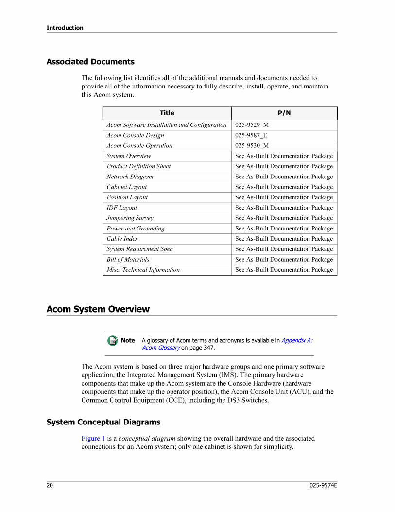
Introduction
20 025-9574E
Associated Documents
The following list identifies all of the additional manuals and documents needed to provide all of the information necessary to fully describe, install, operate, and maintain this Acom system.
Acom System Overview
The Acom system is based on three major hardware groups and one primary software application, the Integrated Management System (IMS). The primary hardware components that make up the Acom system are the Console Hardware (hardware components that make up the operator position), the Acom Console Unit (ACU), and the Common Control Equipment (CCE), including the DS3 Switches.
System Conceptual Diagrams
Figure 1 is a conceptual diagram showing the overall hardware and the associated connections for an Acom system; only one cabinet is shown for simplicity.
Title P/N
Acom Software Installation and Configuration 025-9529_MAcom Console Design 025-9587_EAcom Console Operation 025-9530_MSystem Overview See As-Built Documentation PackageProduct Definition Sheet See As-Built Documentation PackageNetwork Diagram See As-Built Documentation PackageCabinet Layout See As-Built Documentation PackagePosition Layout See As-Built Documentation PackageIDF Layout See As-Built Documentation PackageJumpering Survey See As-Built Documentation PackagePower and Grounding See As-Built Documentation PackageCable Index See As-Built Documentation PackageSystem Requirement Spec See As-Built Documentation PackageBill of Materials See As-Built Documentation PackageMisc. Technical Information See As-Built Documentation Package
Note A glossary of Acom terms and acronyms is available in Appendix A: Acom Glossary on page 347.

21
Acom System Overview
Figure 1: Basic Hardware Arrangement
Console Hardware
The system console hardware is the hardware located at the operator position, mainly the computers and the Acom Console Unit (see Figure 1). The console hardware consists of a PC with monitor that has the necessary software applications to operate the system. The operator position typically includes speakers and microphone equipment for voice capability.
The operator positions are connected to each other by the use of a Local Area Network (LAN). The LAN is used to communicate and distribute management data, application information, configuration files, and ALI/ANI information.
IMS MaintenanceTerminal
Operator PositionAcom Console Unit
RS-232Operator Position
RS-232
Operator PositionRS-232
Operator PositionRS-232
Line Subrack and Circuit Cards
Optical or DS3 Switches
Power Supply
Power Supply
SMU
MCU
SMU
EMU
UIO
MSU
Example of Populated ALS
Common Control Electronics
LAN
LAN
LAN
LANE1
E1
E1
E1
E1 loop to first Acom Console Unit (ACU)
E1
Optical or DS3 Loop
EIE
TIE
Acom Console Unit
Acom Console Unit
Acom Console Unit
Line Subrack and Circuit Cards
Line Subrack and Circuit Cards
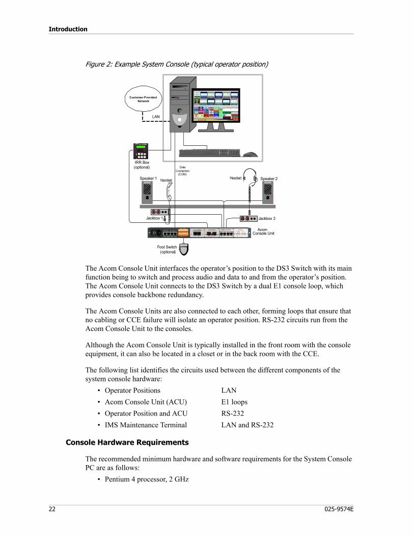
Introduction
22 025-9574E
Figure 2: Example System Console (typical operator position)
The Acom Console Unit interfaces the operator’s position to the DS3 Switch with its main function being to switch and process audio and data to and from the operator’s position. The Acom Console Unit connects to the DS3 Switch by a dual E1 console loop, which provides console backbone redundancy.
The Acom Console Units are also connected to each other, forming loops that ensure that no cabling or CCE failure will isolate an operator position. RS-232 circuits run from the Acom Console Unit to the consoles.
Although the Acom Console Unit is typically installed in the front room with the console equipment, it can also be located in a closet or in the back room with the CCE.
The following list identifies the circuits used between the different components of the system console hardware:
• Operator Positions LAN• Acom Console Unit (ACU) E1 loops• Operator Position and ACU RS-232• IMS Maintenance Terminal LAN and RS-232
Console Hardware Requirements
The recommended minimum hardware and software requirements for the System Console PC are as follows:
• Pentium 4 processor, 2 GHz
DataConnection
(COM)Speaker 1
Foot Switch(optional)
IRR Box(optional)
Speaker 2
Customer ProvidedNetwork
AcomConsole Unit
Headset
Jackbox 2Jackbox 1
Handset
LAN
23
Acom System Overview
• 533 MHz FSB• 512 MB of RAM• 40 GB (or larger) hard drive• CD-ROM 48x• 1.44 MB 3.5” FDD• 2MB (or more) video card
(minimum resolution of 1024 x 768 required)• 1 x RS-232 serial port (or more)• LAN card, 10/100 MB• Flat panel or CRT monitor:
• 19 inch minimum• 1024 x 768 minimum resolution• Touchscreen optional
Electrical Requirements• The power for the system console is 110 or 220 VAC. A selection switch is located
on the back of the PC.
Connectors and pin-outs• DB9 to RJ45 cable to Acom Console Unit. (P/N 709-7615)• RJ-45 connector for LAN
Common Control Equipment (CCE)
The CCE includes the 19-inch, 6-unit equipment racks that contain the Acom Line Subracks (ALS), Acom Digital Switches (ADS), and their associated circuit cards. The CCE is networked to operator positions, providing switching for voice and data communication and dispatch console functions.
Each subrack can hold up to 13 Acom cards. The Acom Line Subracks contain all of the required interfacing to line services. The equipment rack also contains rate converters, modems, power supplies, plus all of the necessary cabling, including the DS3 backbone.
The Acom system provides the necessary signaling functions to properly interface to the line interfaces. The CCE also provides interfaces to the operator console positions through the use of DS3 Switches and an E1 link. See Figure 1.
The Acom system supports the distribution of console configuration files using a Local Area Network (LAN). A maintenance computer running the Integrated Maintenance Software (IMS) provides the system with configuration and diagnostic reporting tools.
Note The only operating systems supported are Windows Vista Business SP1 and Windows XP Professional SP3.
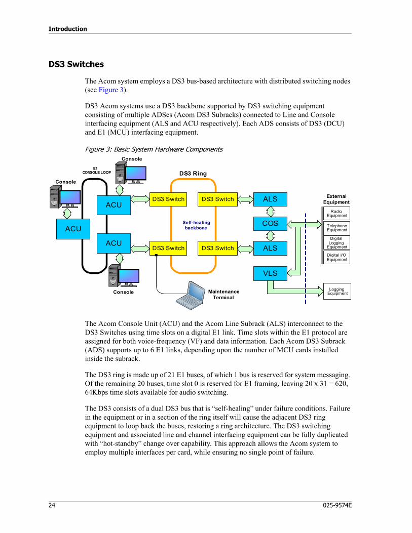
Introduction
24 025-9574E
DS3 Switches
The Acom system employs a DS3 bus-based architecture with distributed switching nodes (see Figure 3).
DS3 Acom systems use a DS3 backbone supported by DS3 switching equipment consisting of multiple ADSes (Acom DS3 Subracks) connected to Line and Console interfacing equipment (ALS and ACU respectively). Each ADS consists of DS3 (DCU) and E1 (MCU) interfacing equipment.
Figure 3: Basic System Hardware Components
The Acom Console Unit (ACU) and the Acom Line Subrack (ALS) interconnect to the DS3 Switches using time slots on a digital E1 link. Time slots within the E1 protocol are assigned for both voice-frequency (VF) and data information. Each Acom DS3 Subrack (ADS) supports up to 6 E1 links, depending upon the number of MCU cards installed inside the subrack.
The DS3 ring is made up of 21 E1 buses, of which 1 bus is reserved for system messaging. Of the remaining 20 buses, time slot 0 is reserved for E1 framing, leaving 20 x 31 = 620, 64Kbps time slots available for audio switching.
The DS3 consists of a dual DS3 bus that is “self-healing” under failure conditions. Failure in the equipment or in a section of the ring itself will cause the adjacent DS3 ring equipment to loop back the buses, restoring a ring architecture. The DS3 switching equipment and associated line and channel interfacing equipment can be fully duplicated with “hot-standby” change over capability. This approach allows the Acom system to employ multiple interfaces per card, while ensuring no single point of failure.
ACU
ACU
DS3 Switch
DS3 Switch
COS
ALS
ALS
VLS
External EquipmentDS3 Switch
DS3 Switch
LoggingEquipment
ACU
E1CONSOLE LOOP DS3 Ring
Console
Self-healingbackbone
RadioEquipment
TelephoneEquipment
DigitalLogging
Equipment
Digital I/OEquipment
Maintenance Terminal
Console
Console
25
Acom System Overview
Intersite Bearers
An intersite bearer (ISB) is a means of sharing resources among two or more sites that are connected within the same Acom system but may be miles apart. Using ISB links, resources at one site can be used by console operators at any connected site. A console operator at Site A can answer a call being received at Site B and can transmit over a line that is physically located at Site B. Console operators at remote sites can be included in conferences, patches, and intercoms just as if they were local. A typical usage is transmitting from Site A to a radio that is out of range of Site A but within range of Site B.
No difference should be noticed between local and remote lines, except possibly a slightly slower response time on lines that actually reside at another site. Line and console numbers are unique among all sites, so there’s no danger of confusing, for example, Console 10 and Radio Line 20 with any other console and line.
Optionally, ISBs can also carry digital I/O for voting monitor and control of remote radio lines. When this option is enabled, some digital I/O can be configured to pass over ISBs with other digital I/O remaining local.
ISB connections are implemented between ADSs of separate Acom sites, by way of E1 or T1 connections on the MCU4 cards. Every ISB has an Incoming and an Outgoing side. That is, one MCU4 port must be configured as an Incoming bearer, and the mating MCU4 port on the other site must be configured as an Outgoing bearer. Each ADS can support up to six ISBs, and there can be up to 16 ISB groups in a network. Extended bearers are used on a point-to-point basis to complement the Main bearer.
Each ISB port is monitored for stability. If a certain number of destabilizing events should occur within a certain period of time, the port would be temporarily disabled. If port is configured for redundancy, this would cause a change-over to a Standby ISB group. The port would remain unavailable until a certain number of stabilizing events occurred within a certain period of time. The port would then be enabled again, and a change-over of the bearer group back to the Main group should occur. The event types, time parameters, and redundancy are specified by way of IMS ADS.
In addition to IMS ADS, some ISB setup may need to be done in IMS ALS and/or IMS ACU, as well as in Acom Console Designer. For more information on ISBs, and for configuration procedures, see To set up intersite bearers (ISBs) in Acom Software Installation and Configuration.
Time Slots
A time slot can be thought of simply as a data transmission unit on the E1 link. (For a more detailed definition, see time slot and frame in the glossary.)
Backbone Time Slots for Local Resources
Each uniquely identifiable resource (radio lines, phone lines, ringdown lines, intercom lines and utility audio devices) requires a backbone time slot for communication between the console and the CCE. Each console also requires a backbone time slot, and each
Introduction
26 025-9574E
system tone generator requires a backbone time slot. Consoles automatically request a backbone timeslot as soon as the operator is online (logged into ACS software).
Console screens can be designed to have a Backbone Status indicator that monitors the supply of backbone time slots. If the indicator should turn from green (which indicates <90% of the backbone time slots are in use) to yellow (which indicates that 90-99% are in use), the console operator would be expected to review the resources in use by that console and determine whether any can be released. If the indicator should turn to red (which indicates that 100% are in use), resource selection is possible, but the audio is not available until another active resource is released.
Phone/Radio line resources can be allocated backbone time slots either permanently or dynamically:
• Permanent allocation — The time slot will be allocated from the time slot pool when the line first starts up, guaranteeing that the line can always receive and send audio.
• Dynamic allocation — The time slot will be allocated from the time slot pool on an as-needed basis (for example, when an operator selects or monitors the line).
The rationale behind the dynamic allocation design is the same as with all trunking type designs, such as all public phone networks: all physical circuits are not typically in use at any given time. As long as the traffic model is understood, it is possible to have many more potential connections than there are physical circuits.
Acom’s dynamic allocation model supports prioritization of the circuits to be switched in case the backbone time slots are ever full when an attempt to access a circuit is made. If an accurate traffic model is known and Acom is configured correctly, this situation should not occur. However, if it does, the following priorities are used (listed with highest priority first):
1. consoles2. permanent phone lines3. permanent radio lines4. fixed connections5. system tones6. utility audio7. dynamic phone lines8. dynamic radio lines
Bearer Time Slots for Intersite Resources
Each audio resource usage (such as monitoring a line, selecting a line, or joining a conference) over an ISB link requires a bearer time slot.
Like backbone time slots, bearer time slots can be made available for resource use across an intersite bearer either dynamically (as needed) or permanently.

27
Acom System Overview
Console screens can be designed to have a Bearer Status indicator that monitors the supply of bearer time slots. If the indicator should turn from green (which indicates <90% of the bearer time slots are in use) to yellow (which indicates that 90-99% are in use), the console operator would be expected to review the resources in use by that console over ISB links and determine whether any can be released. If the indicator should turn to red (which indicates that 100% are in use), resource selection is possible, but the audio is not available until another active resource is released.
Capacity
Using dynamic allocation of backbone time slots, an Acom system can support up to 200 consoles and 2,200 lines. The actual maximum number of consoles and lines that can be active in the system at any given time depends on the extent to which dynamic allocation is used.
In a multi-site system employing intersite bearers, the maximum number of consoles and lines that can be active in the system at any given time further depend on how many consoles and lines are configured for replication, and the extent to which the bearer time slots are allocated dynamically.

Introduction
28 025-9574E
29
Installation Preparation
This chapter describes the steps necessary to prepare for Acom installation. These instructions are guidelines and contain sufficient information to help you install the equipment, however, you will need project-specific information to completely install the equipment. See Associated Documents on page 20.
The installation procedures in this chapter are:
General Preparation on page 30Operating Environment on page 30Safety on page 30System Architecture on page 31As-Built Documentation on page 32
Back Room (CCE) Preparations on page 33Recommended Installer Materials and Equipment on page 33Testing of New/Existing Circuits on page 34Install Additional Power on page 35Install Grounding System on page 36Install Cable Trays on page 37Mount Acom Punchdown Blocks on Demarc Wall on page 38Lightning Protection on page 38Check Cabinet Route on page 39Environment on page 39
Front Room (Console) Preparations on page 40Console Loop Installation on page 40Twisted Pair Loops on page 40Coax Loops on page 41Patch Panel on page 42Console Network Installation on page 42
Installation Preparation
30 025-9574E
General Preparation
Zetron cabinets that house the subracks are staged at the factory and are typically installed on site by Zetron technical personnel. Any installation is preceded by a site analysis and preparation to ensure that the equipment is in a proper operating environment. The following guidelines are considered part of the site preparation; all equipment specifications must be maintained.
• Adequate space must be available for ingress of cabinets and equipment.• Space requirements must allow for proper placement of equipment and safely
accommodate cabling.• Space requirements must allow for safe access to equipment so that personal can
properly service and maintain the equipment.• Support flooring must be able to adequately anchor cabinets according to local
codes and practices.• Adequate ventilation and cooling must be available for proper equipment operation.• Adequate space must be available for cable trays if required.
Operating Environment
The Acom is designed for installation and operation within areas suitable for telecommunications equipment. Environmental factors such as air temperature and humidity and presence of electromagnetic interference (including line disturbances) may affect reliability and reduce system availability.
The requirements for temperature and humidity are listed in the Absolute Maximum Ratings paragraph listed in the Acom Line Subrack Specifications, page 100. Note that the specifications are for the ambient air surrounding the subrack. Compliance with the specifications must also consider measuring the air temperature in the space directly below the subrack.
Other guidelines relating to the installation environment are as follows:• The installation environment must be free of dust, moisture and vapor. The subrack
is designed for ease of access to cards and for cable entry. It is not protected against ingress of particles or liquids that may deposit on the surfaces of the circuit cards and on the metallic surfaces of connectors.
• The installation environment must be free of excessive vibration and shock.
Safety
There are two types of circuits that can be connected to an Acom.• Telecom Network Voltage (TNV)• Safety Extra Low Voltage (SELV)
31
General Preparation
The TNV circuits are designed to connect to external lines and may carry hazardous voltages.
Because it is possible to work on the Acom system when the equipment is live and connected to external circuits, extreme care must be exercised to avoid touching a TNV. Those areas include the front sections of cards and the subrack’s lower backplane.
Incoming cabling will also be connected to TNV circuits and may carry hazardous voltages.
Antistatic Work Practice
All Acom system cards are static sensitive; handling and installation must take place within antistatic work areas. The recommended guidelines for antistatic work practice are as follows:
• The area should be free of unnecessary paper, plastic, or other static producing items.
• Only conductive or antistatic materials may be used for storage and packaging of cards.
• Workbenches should have an antistatic work surface (such as a conductive mat) connected to a protective earth.
• Personnel should use conductive wrist or ankle straps connected to earth through a suitable resistance.
• The antistatic system should be connected to the same protective earth as the rack.• Care should be exercised to minimize human contact with conductive areas of
circuit cards. Contact at handles and at card edges, not the connectors, is preferred. There should be no contact with a card and human hair or clothing.
• Racking equipment should be constructed with ESD earth-bond points for convenient connection of wrist straps when installing or removing cards and subracks.
Before you begin installation, review this manual, the “As-Built” documentation, and the manuals listed below. The sections in this manual are prepared in a sequence in which the system should be installed. If you need further assistance, please call Zetron. The contact information can be found at http://www.zetron.com. There may be a fee charged for providing service outside of normal business hours.
System Architecture
Acom consists of Acom Line Subracks (ALS), Acom DS3 Subracks (ADS), Acom Console Units, Acom Router Console Units, Acom Changeover SubRacks (CSR), -48VDC power supplies, and other associated Acom and third-party hardware. A DS3 ring is used to connect the switching devices.
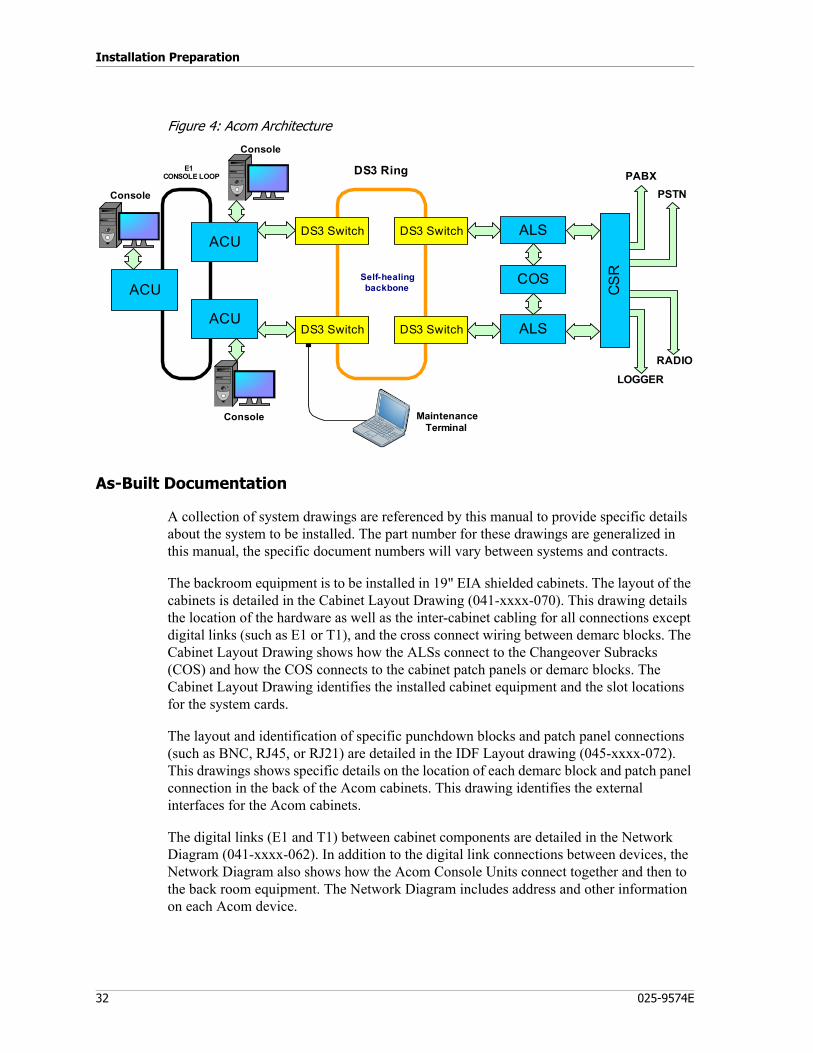
Installation Preparation
32 025-9574E
Figure 4: Acom Architecture
As-Built Documentation
A collection of system drawings are referenced by this manual to provide specific details about the system to be installed. The part number for these drawings are generalized in this manual, the specific document numbers will vary between systems and contracts.
The backroom equipment is to be installed in 19" EIA shielded cabinets. The layout of the cabinets is detailed in the Cabinet Layout Drawing (041-xxxx-070). This drawing details the location of the hardware as well as the inter-cabinet cabling for all connections except digital links (such as E1 or T1), and the cross connect wiring between demarc blocks. The Cabinet Layout Drawing shows how the ALSs connect to the Changeover Subracks (COS) and how the COS connects to the cabinet patch panels or demarc blocks. The Cabinet Layout Drawing identifies the installed cabinet equipment and the slot locations for the system cards.
The layout and identification of specific punchdown blocks and patch panel connections (such as BNC, RJ45, or RJ21) are detailed in the IDF Layout drawing (045-xxxx-072). This drawings shows specific details on the location of each demarc block and patch panel connection in the back of the Acom cabinets. This drawing identifies the external interfaces for the Acom cabinets.
The digital links (E1 and T1) between cabinet components are detailed in the Network Diagram (041-xxxx-062). In addition to the digital link connections between devices, the Network Diagram also shows how the Acom Console Units connect together and then to the back room equipment. The Network Diagram includes address and other information on each Acom device.
PABX
LOGGER
ACU
ACU
COS
ALS
ALS
ACU
E1CONSOLE LOOP DS3 Ring
Console
Self-healingbackbone
Maintenance Terminal
Console
Console
DS3 Switch
DS3 Switch
DS3 Switch
DS3 Switch
CS
R
PSTN
RADIO
33
Back Room (CCE) Preparations
Power for most devices is provided by a -48VDC supply that derives its output from a 115VAC input source. The power supplies may feed fuse or circuit breaker panels located in each cabinet to distribute the power. Each device in the cabinet must be grounded to a copper ground bar located within the Acom cabinet. The ground bars within each cabinet must be earth grounded by an electrician before power is applied. The specific details on power and grounding of the Acom cabinets can be found in the Power and Ground Diagram (045-xxxx-074).
Recommended Installer Materials and Equipment
• Helper Instruments LineMan test box, VF meter, or equivalent• Zip ties, various sizes• Velcro, various sizes• Split loom for dressing positions• Multimeter, Fluke DMM, or equivalent• Label maker or other cable labels• Cordless drill w/square bit for 8x3/4 screws• RJ45 crimp tool and connectors• BNC crimp tool and connectors• ESD wrist strap with alligator clip• Assorted tools including screw drivers• Work light• Step ladder• Telephone test set, “Butt Set”, or equivalent
Back Room (CCE) Preparations
Prior to system installation the site must be prepared for the Acom system. The specific details of expected modifications or actions to be performed prior to system installation are detailed in the Site Interface Requirements document (041-xxxx-yyy). This document will describe the cabling, power, ground, environmental conditions, circuit interfaces, and physical and electrical requirements that must be met prior to system installation. It will describe what to expect during installation to include the physical dimensions of the equipment, cable lengths to be provided, and equipment to be provided by the customer. This section is meant to provide only generalizations of how to prepare the site for the Acom system.
Installation Preparation
34 025-9574E
Testing of New/Existing Circuits
The installer is responsible for the testing/measurement of all customer circuits prior to equipment installation. These tests should be done as soon as possible to avoid installation delays.
♦ To test POTS circuits (exchange, end-end, loop out/ring in):
1. Place a telephone test set or analog desk phone across the Tip and Ring of each circuit. Take the phone off-hook and verify it returns dial tone.
2. Place an outgoing call and verify the call is connected.3. Ask the remote party to press and hold the DTMF 5 key on their phone and
measure the level at the customer demarc. Record this level in either Vrms or Dbm.
♦ To test local radio channels (PTT/COR):
1. Measure the receive level from the radio by generating an incoming signal (from radio) using either a test set or a mobile radio. a. Radio Service Monitor Method - If using a service monitor, generate a 1000Hz
sine wave at %60 deviation at full quieting (FM) or %90 modulation (AM). Record the level on the receive pair from the radio.
b. Voice Method - Key up a mobile unit and say a long deep “four” or another deep powerful sound and measure the level from the radio in either Vrms or dBm.
c. DTMF Method - Key up a mobile unit and press the mobile’s DTMF 5 key. Most mobiles generate DTMF at %60 deviation (FM). Measure the level of receive audio from the radio.
2. Verify that grounding the PTT lead keys the transmitter. Momentarily ground the PTT line to the transmitter and verify the base station keys. Record your results.(Some base stations require power to key instead of ground.)
3. Verify the receiver provides a COR signal on carrier presence. Measure the COR lead from the receiver and generate a signal on the channel to break squelch. Note the signaling state change.
4. Verify the required Tx audio level to generate %60 deviation (FM) or %90 modulation (AM).a. Generate a 1000Hz tone using a VF test box such as the Helper Line Master at
-10dBm onto the base station's transmit pair. b. Activate the transmitter by signaling the PTT line and measure the transmitter's
deviation (FM) or modulation (AM).c. Record your results.
♦ To test Tone Remote radios:
1. Measure the receive level from the radio by generating an incoming signal (from radio) using either a test set or a mobile radio.
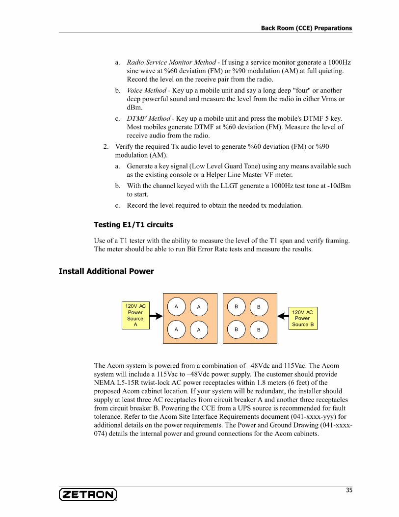
35
Back Room (CCE) Preparations
a. Radio Service Monitor Method - If using a service monitor generate a 1000Hz sine wave at %60 deviation (FM) or %90 modulation (AM) at full quieting. Record the level on the receive pair from the radio.
b. Voice Method - Key up a mobile unit and say a long deep "four" or another deep powerful sound and measure the level from the radio in either Vrms or dBm.
c. DTMF Method - Key up a mobile unit and press the mobile's DTMF 5 key. Most mobiles generate DTMF at %60 deviation (FM). Measure the level of receive audio from the radio.
2. Verify the required Tx audio level to generate %60 deviation (FM) or %90 modulation (AM).a. Generate a key signal (Low Level Guard Tone) using any means available such
as the existing console or a Helper Line Master VF meter.b. With the channel keyed with the LLGT generate a 1000Hz test tone at -10dBm
to start.c. Record the level required to obtain the needed tx modulation.
Testing E1/T1 circuits
Use of a T1 tester with the ability to measure the level of the T1 span and verify framing. The meter should be able to run Bit Error Rate tests and measure the results.
Install Additional Power
The Acom system is powered from a combination of –48Vdc and 115Vac. The Acom system will include a 115Vac to –48Vdc power supply. The customer should provide NEMA L5-15R twist-lock AC power receptacles within 1.8 meters (6 feet) of the proposed Acom cabinet location. If your system will be redundant, the installer should supply at least three AC receptacles from circuit breaker A and another three receptacles from circuit breaker B. Powering the CCE from a UPS source is recommended for fault tolerance. Refer to the Acom Site Interface Requirements document (041-xxxx-yyy) for additional details on the power requirements. The Power and Ground Drawing (041-xxxx-074) details the internal power and ground connections for the Acom cabinets.
A
A
A
A
120V ACPower
Source B
120V ACPowerSource
A
B
B
B
B
Installation Preparation
36 025-9574E
Install Grounding System
Each Acom cabinet will come equipped with a copper ground bar mounted within the cabinet. All of the cabinet’s components will be grounded to this bar. The cabinet’s copper ground bar should be connected to earth ground (cold water pipe) for safety. The grounding of the Acom cabinets should be done by a qualified electrician to meet electrical codes. Do not jumper the grounds between Acom cabinets together, each cabinet should have its own high gauge (6 to 16mm2 (10 to 6 AWG)) stranded copper wire connected to the equipment room’s ground point.
If the back room does not already have a suitable ground system, one should be installed that supplies a copper ground plate within 15 meters (50 feet) of the intended cabinet location. The Power and Ground Drawing (041-xxxx-074) details the internal power and ground connections for the Acom cabinets.
A "star" grounding system (a single point ground to which satellite grounds are connected) is the best grounding system. The central "star" point must be firmly attached to a low impedance earth ground point, such as a ground rod. If protective punch-down blocks are used, a large diameter (16 mm2 (6-gauge)) copper conductor (or an equivalent braided strap/bus bar) must be connected between each block's ground lug and the earth ground or central "star" ground point. With the protected punch-down blocks, it is best to wire directly to earth ground if possible. Each piece of equipment should have its chassis grounded to the central "star" point with a separate ground wire. The size of the wire depends on the length of the run, 4mm2 (12 gauge) is adequate if the length is less than 4.5 meters (15 feet). The length of the runs should be minimized. Securely connect a grounding wire to the case of each unit making sure metal connection is made (no paint or oxidation layer). Most Zetron equipment provides a grounding stud. If the console includes a computer, connect an individual grounding wire to the computer chassis. Figure 5 shows a central "star" grounding system. All earth grounds in the system should be isolated from signal lines. It is easy to couple ESD or lightning noise spikes if these lines run parallel for any distance. The AC power wires (and DC power to a lesser degree) should also be routed separately. AC lines can have large switching current noise spikes that could couple into signal lines.
DANGER! Improper system grounding can cause electric shock to personnel, damage to equipment, and system malfunctions. Proper earth grounding is an important electrical consideration. The earth ground protects the system and personnel from lightning strikes, provides a path for any electrostatic discharge (ESD), and provides a solid reference for the system. Improper grounding of the system could cause susceptibility to ESD, induced noise from input power wiring, and reduced effectiveness of lightning protection devices. Induced noise could cause false signal indications or a variety of system errors.
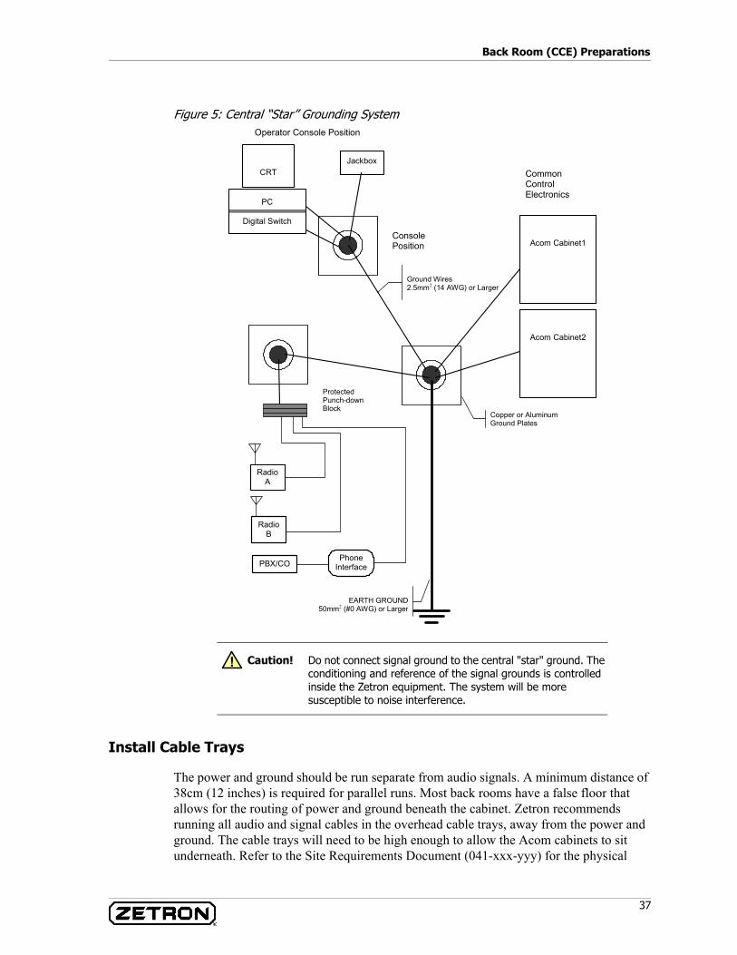
37
Back Room (CCE) Preparations
Figure 5: Central “Star” Grounding System
Install Cable Trays
The power and ground should be run separate from audio signals. A minimum distance of 38cm (12 inches) is required for parallel runs. Most back rooms have a false floor that allows for the routing of power and ground beneath the cabinet. Zetron recommends running all audio and signal cables in the overhead cable trays, away from the power and ground. The cable trays will need to be high enough to allow the Acom cabinets to sit underneath. Refer to the Site Requirements Document (041-xxx-yyy) for the physical
Copper or Aluminum Ground Plates
Ground Wires 2.5mm2 (14 AWG) or Larger
EARTH GROUND50mm2 (#0 AWG) or Larger
Acom Cabinet1
Common Control Electronics
CRT
PC
Digital Switch
Jackbox
Console Position
Protected Punch-downBlock
Radio A
Radio B
Phone InterfacePBX/CO
Acom Cabinet2
Operator Console Position
Caution! Do not connect signal ground to the central "star" ground. The conditioning and reference of the signal grounds is controlled inside the Zetron equipment. The system will be more susceptible to noise interference.
!
Installation Preparation
38 025-9574E
dimensions of the Zetron cabinets. The cable trays should provide a path for voice and signal cable routing between the Acom cabinets and the demarc wall.
Mount Acom Punchdown Blocks on Demarc Wall
The telco, radio, and digital I/O interfaces are typically provided via a 25-pair RJ21X punch-down terminal which has CO/PABX wiring on one side and open terminals on the other side. RJ21X terminals are wired to a 25-pair connector jack on the side of the terminal block. A 25-pair connectorized cable interfaces from the terminal block jack to the CO/PABX equipment. The terminals are punched directly to cabling on both sides, eliminating the 25-pair cable connectors.
RJ21X Split-Blocks (Zetron Part No. 802-0263 or equivalent) are configured with 4 terminals side to side by 50 terminals top to bottom. From side to side, the two left terminals in each row are electrically identical, and the two right terminals are electrically identical. The two left terminals are isolated, however, from the two right terminals. Normally, “bridging” clips are installed onto the two center terminals in order to connect the right-side wiring to the left-side circuits. This provides a means of “opening” circuits (by removing bridging clips) or temporarily re-routing lines (by cross-wiring different circuits) for test purposes. Terminal numbering from top to bottom starts with RJ21 pin26, then pin1, then 27, then 2 as shown below.
Also, paired bridging clips (convenience) and fused bridging clips (surge protection) are available from other vendors to facilitate these circuit terminals.
The Acom system will require a dedicated space on the wall for the demarcation of Acom circuits. A 1200x2400mm sheet of 18mm plywood (4x8x¾”) should be painted white and bolted to the wall at this location. Mount the split-block type punchdown block to the demarc wall in preparation for Acom system installation. The Acom 25-pair cables will come terminated to an RJ21 connector for direct connection to connectorized type 66 blocks. By providing accurate lengths between the proposed cabinet location and the demarc wall, cables of the necessary length can be provided. The customer may at their discretion, cut off the RJ21 and terminate the cables by punching down all of the connections to the exact length. Refer to the Site Requirements Document (041-xxxx-yyy) for the number and use of the type 66 blocks.
Lightning Protection
Arc arresters right on the telephone demarcation/punch-down blocks can shunt hazardous voltages at their source. These easily replaceable protection modules protect your equipment investment. Ask your Zetron sales person how to order punch down blocks with built in protectors.
Additional protection for the primary power line may be obtained from other vendors, and should be employed to protect from lightning strikes to power lines.
Proper grounding techniques are critically important to ensure proper lightning suppression and reliable operation of the Acom Console System.
39
Back Room (CCE) Preparations
Lightning grounds are typically routed directly from lightning arrestors/suppressors to the main ground bonding terminal, which in turn is typically soldered or welded directly to the site grounding network (ground rods, etc.). Each lightning protection device should be grounded separately with the shortest possible wire length to the bonding junction. To minimize path resistance and impedance, a large-diameter wire (typically 16mm2 (4 AWG)) green-colored conductor is used, having minimum bend radii of 20cm (8 inches) to minimize inductive effects. Also, other wires should be separated at least 10cm (4 inches) from these grounds to prevent arc-over during lightning strikes.
Further information is provided in Zetron Technical Bulletin 027-0069: Proper Signal Grounding Techniques for Radio Sites.
Check Cabinet Route
Walk the path you expect to use when moving the Zetron cabinets to the CCE and measure all ceilings, elevators, and doorways for clearance. Check this against the cabinet dimensions to ensure a smooth installation.
Environment
Ensure that the CCE is cool, dry, and relatively dust free. Air conditioning may be required to keep the room at a constant temperature. The use of fans by the Acom equipment is kept to a minimum.
Suggested conditions:
• Temperature: below 21.7 C (71 F)• Humidity: below 50% non-condensing
Warning! Operating the Acom Console System without adequate voltage suppression devices on the telephone and radio connections may result in costly damage not covered by warranty. Protection kits and applications assistance are available from Zetron.
STOP
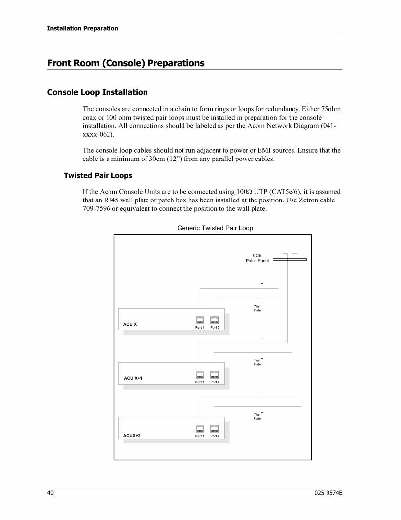
Installation Preparation
40 025-9574E
Front Room (Console) Preparations
Console Loop Installation
The consoles are connected in a chain to form rings or loops for redundancy. Either 75ohm coax or 100 ohm twisted pair loops must be installed in preparation for the console installation. All connections should be labeled as per the Acom Network Diagram (041-xxxx-062).
The console loop cables should not run adjacent to power or EMI sources. Ensure that the cable is a minimum of 30cm (12”) from any parallel power cables.
Twisted Pair Loops
If the Acom Console Units are to be connected using 100Ω UTP (CAT5e/6), it is assumed that an RJ45 wall plate or patch box has been installed at the position. Use Zetron cable 709-7596 or equivalent to connect the position to the wall plate.
Port 1 Port 2
Port 1 Port 2
ACU XPort 1
Generic Twisted Pair Loop
Port 2
ACU X+1
ACUX+2
CCEPatch Panel
Wall Plate
Wall Plate
Wall Plate
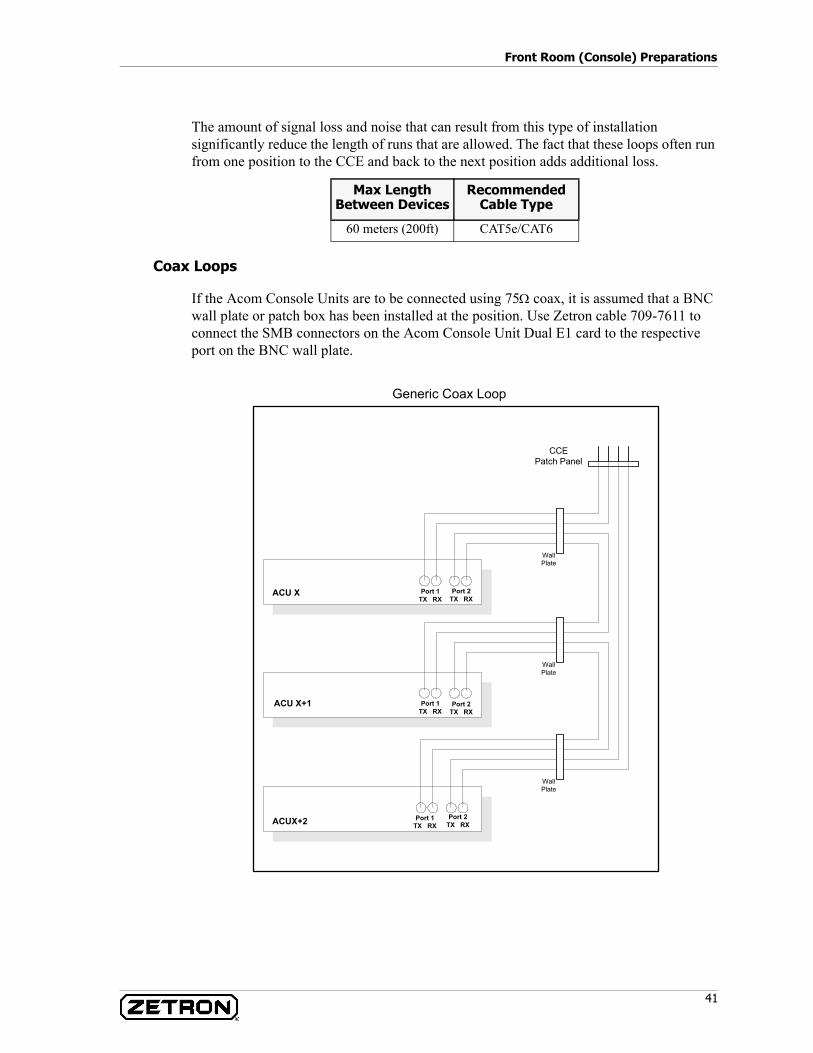
41
Front Room (Console) Preparations
The amount of signal loss and noise that can result from this type of installation significantly reduce the length of runs that are allowed. The fact that these loops often run from one position to the CCE and back to the next position adds additional loss.
Coax Loops
If the Acom Console Units are to be connected using 75Ω coax, it is assumed that a BNC wall plate or patch box has been installed at the position. Use Zetron cable 709-7611 to connect the SMB connectors on the Acom Console Unit Dual E1 card to the respective port on the BNC wall plate.
Max Length Between Devices
Recommended Cable Type
60 meters (200ft) CAT5e/CAT6
ACU X Port 1TX RX
Generic Coax Loop
Port 2TX RX
ACU X+1 Port 1TX RX
Port 2TX RX
ACUX+2 Port 1TX RX
Port 2TX RX
Wall Plate
Wall Plate
Wall Plate
CCEPatch Panel
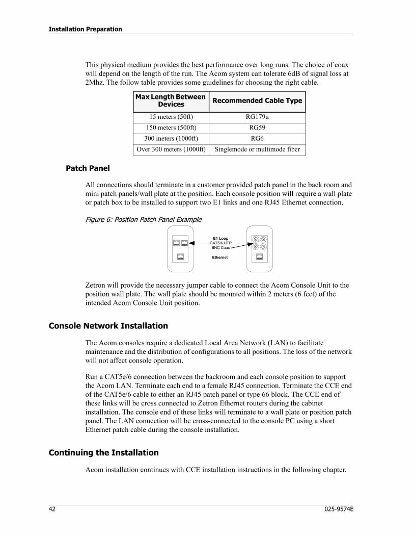
Installation Preparation
42 025-9574E
This physical medium provides the best performance over long runs. The choice of coax will depend on the length of the run. The Acom system can tolerate 6dB of signal loss at 2Mhz. The follow table provides some guidelines for choosing the right cable.
Patch Panel
All connections should terminate in a customer provided patch panel in the back room and mini patch panels/wall plate at the position. Each console position will require a wall plate or patch box to be installed to support two E1 links and one RJ45 Ethernet connection.
Figure 6: Position Patch Panel Example
Zetron will provide the necessary jumper cable to connect the Acom Console Unit to the position wall plate. The wall plate should be mounted within 2 meters (6 feet) of the intended Acom Console Unit position.
Console Network Installation
The Acom consoles require a dedicated Local Area Network (LAN) to facilitate maintenance and the distribution of configurations to all positions. The loss of the network will not affect console operation.
Run a CAT5e/6 connection between the backroom and each console position to support the Acom LAN. Terminate each end to a female RJ45 connection. Terminate the CCE end of the CAT5e/6 cable to either an RJ45 patch panel or type 66 block. The CCE end of these links will be cross connected to Zetron Ethernet routers during the cabinet installation. The console end of these links will terminate to a wall plate or position patch panel. The LAN connection will be cross-connected to the console PC using a short Ethernet patch cable during the console installation.
Continuing the Installation
Acom installation continues with CCE installation instructions in the following chapter.
Max Length Between Devices Recommended Cable Type
15 meters (50ft) RG179u150 meters (500ft) RG59
300 meters (1000ft) RG6Over 300 meters (1000ft) Singlemode or multimode fiber
Ethernet
E1 LoopCAT5/6 UTPBNC Coax
CCE Installation
43
CCE Installation Procedures
This chapter describes the steps necessary to install the CCE (back room) and the IMS terminal. These instructions are guidelines and contain sufficient information to help you install the equipment, however, you will need project-specific information to completely install the equipment. See Associated Documents on page 20.
The installation procedures in this chapter are:
CCE Installation on page 43System Power Up and Reset on page 46
CCE Installation
Inventory the delivered hardware against the Zetron pack slip to verify all equipment was included. Many accessories are bundled into the Acom Console Unit box.
Unpack and Position the Cabinets
When the cabinets arrive they will be crated. Four people and a large area of 6x6 meters (20x20 feet) will be required to unbox the cabinets. An electric screw driver will assist in the removal of the top and side of the crate. The cabinets will ship with the doors removed and stored in the crate. With the top and side removed from the shipping crate, slide the cabinet out of the crate and stand it up on the wheels. Roll the cabinet into the desired location in the equipment room. To secure the room against vibration from earthquakes the installer may remove the wheels and bolt the cabinets to the floor.
The doors should remain off until installation and commissioning is complete. They must be installed to provide FCC part15 compliance for emissions.
CCE Installation Procedures
44 025-9574E
Remove Zip Ties
The cables that are intended to be permanently installed will be secured with Velcro or hook/loop tape. The use of Velcro reduces any stress put on the cables. Cables or hardware secured with Zip-Ties are intended to be temporary for shipping purposes only. Cut all zip ties to free cables for installation.
Install Rackmount Servers
If the Acom system shipped with a rack mount PC or server, install that now. Refer to the Cabinet Layout (041-xxxx-070) for the location of the rack mount server. This task will require two people.
Once installed, the servers will require AC power connections to the Acom rack mounted power strips and grounding to the copper ground bar within the cabinet. Refer to the Network Diagram (041-xxxx-062) for the serial connection details.
If any Ethernet routers were shipped with the system, install them now. They may need to be rack mounted, refer to the Cabinet Layout Drawing (041-xxxx-070) for specific locations.
Connect Earth Ground
All the equipment within the Acom cabinets has been grounded to a copper bus bar. Have an electrician connect each Acom cabinet’s copper ground bar to the building’s earth ground. A separate connection to the room’s primary ground point should be used for each cabinet.
Connect Cabinets to Demarc Blocks
Following the Cross Connect Document (041-xxxx-yyy) to connect the Acom equipment to the demarc wall using 25-pair cables. The signaling cables should be run away from power sources to prevent noise from coupling. Each cable that leaves the Acom cabinets will terminate on a patch panel. Radio and telephone circuits may terminate on a RJ21 patch panel on the rear of the Acom cabinets. The installer may plug the 25-pair cables directly to the connectorized Acom type 66 blocks or cut off the cable’s end and punch them down to get an exact length. Avoid running the 25-pair cables over sharp edges or creating kinks in the cable. Preserve a 25mm (1”) min bend radius for the CAT3 25-pair cables.
Cross-Connect Acom Blocks to Existing/New Circuits
Using solid 24 awg wire, cross connect each circuit to the Acom type 66 blocks. The Acom demarc details and block pinouts can be found in the Cross Connect Document (041-xxxx-yyy).
45
CCE Installation
Acom Cabinet- to-Cabinet Connections
Following the Cross Connect Document (041-xxxx-yyy) connect the Acom cabinets together using coax, 25-pair CAT3, or 4-pair CAT5. All connections out of the cabinet will terminate on a patch panel in the back of the cabinet. The patch panel jacks have a unique identifier that can be used to locate specific connections.
Connect Acom Cabinets to Console Loops
Install runs of 75ohm coax or 100ohm UTP cable between the patch panels in the rear of the Acom cabinets to the backroom termination point for the Acom console loops. The specific connections can be found in the Cross Connect Document (041-xxxx-yyy).
Install Cards
Ground yourself to the Acom cabinet using an ESD wrist strap prior to installing or removing Acom cards. The system cards are shipped separate from the cabinets to protect them during shipment. Use the Cabinet Layout Drawing (0451xxxx-070) to populate the Acom Line Subracks (ALS), Changeover Sub Racks (CSR), and Acom DS3 Racks (if applicable) with the Acom system cards and make the needed connections to the front of each card. Verify the serial number and card type against the provided as-built records. The cables that connect to the front of each card will be labeled with the designators of the port at each end.
Apply Power
The cabinets will require 110AC power. Plug in the twist lock connections for the 48VDC power supplies and any Acom 110AC rack mounted power strips to the customer provided power receptacles. The redundant power supplies should be plugged into different AC circuits to prevent a single point of failure.
Apply power to the Acom cabinets by closing the circuit breakers in the –48vdc power supplies. The equipment connected to each breaker is designated in the Power and Ground Drawing (041-xxxx-074). Turn on the power switch for the AC power strip to provide 110VAC power to the cabinets. Turn on any ADS by toggling the MSU switch on (down).
Next turn on each of the Acom Line Subracks (ALS) by toggling the MSU switch on (down). Verify that the MSU LEDs light and the MCU initializes. Refer to the card LED information in Table 130 on page 206.
Check each cabinet’s fuse distribution panel for any alarms.
Check the –48v power supply for any alarms.
Check each device for a “Run” indication.
CCE Installation Procedures
46 025-9574E
Network
Run jumper cables between all of the network ports for the positions to the Acom LAN router. The router may be rack mounted in one of the Acom cabinets or may just sit on a shelf. Generally speaking it does not matter what port each console is connected to, however, use caution when connecting a device to the last port of the router as it may be switched for use as an uplink expansion port. Each LAN port on the router will have an LED to indicate a connectivity and activity.
Maintenance Terminal
The maintenance terminal is a PC that is dedicated to monitoring the system and is used for maintenance and diagnostics. Install the maintenance PC in the CCE within 50 feet of the Acom cabinets. The recommended location would be in an adjacent rack (on a shelf) or on a nearby table.
For DS3 switches, connect serial cable 709-7615 between COM1 of the maintenance PC and on J8 port 1 (right port) on the front of the DS3 card near the bottom. Connect the Ethernet port on the front of each DS3 card to a free port on the Ethernet LAN router.
Connect the Ethernet port of the Maintenance terminal to a free port on the LAN router. Make the appropriate PC connections and turn them on. Reboot the maintenance terminal PC. Start the IMS Terminal (Net_Mgr) application on the Maintenance terminal PC and verify all CCE devices show communications. No communication with the Acom Console Units and some urgent system alarms will be normal at this time because the console loops have not been connected.
System Power Up and Reset
System Power Up Sequence
The power up procedure in this section is to be used on an Acom system that is known to be configured and functional.
47
System Power Up and Reset
Power Up Sequence
♦ To power up an Acom system:
1. Power up all DS3 Switches.2. Wait two minutes after all DS3 Switches have been powered on before proceeding
to next step.3. Power up side ‘A’ of the Acom system ALSs. These would normally be all ALSs
with the names of ALS1A or an ‘A’ in the name after the word ALS. These ALSs are sometimes referred to as the Main ALSs.
4. Wait one minute after all ALSs on the ‘A’ side have been powered on before proceeding to the next step.
5. Power up side ‘B’ of the Acom system ALSs. These would normally be all ALSs with the names of ALS1B or a ‘B’ in the name after the word ALS. These ALSs are sometimes referred to as the Standby ALSs.
6. Wait one minute before proceeding to the next step.7. The system should be active on the ‘A’ side of the Acom Equipment. This can be
verified by looking at the Information Alarm LED on the ALSs. This is the Green LED located on the MSU card right below the power switch next to the Yellow and Red LED’s. All ALSs on the ‘A’ side should have the Information Alarm LED on and the ‘B’ side ALSs should have the Information Alarm LED off.
8. If IMS Terminal/Net_Mgr is available, verify that all ALSs are now reporting to the software.
9. Power up all Acom Console Units in the system.10. Wait at least one minute after the last Acom Console Unit in the system has been
powered on for all Acom Console Units to come online.11. If IMS Terminal/Net_Mgr is available, verify that all Acom Console Units are now
reporting to the software.12. Start Acom Console Software at each position and logon to a screen.13. The Acom system should now be up and ready for operation.
Restart
The redundant and self-healing nature of the system design implies that only an unusual event (like a total power failure) would require restarting the entire system. In such an event, the procedure is no different than it was for the initial startup.
Note Verify that all Acom equipment is powered down/off before starting the power up sequence. This includes all Acom Console Units, DS3 Switches, ADSs, and ALSs in the system. Also verify that Acom Console Software is not running. If Acom Console Software is running, select the Configure button and select Exit to Windows.
CCE Installation Procedures
48 025-9574E
In the case of system components that were switched off for repair or replacement, they may be started again at any time. Once they have cleared reset and finished their self-tests, the IMS application is used to finish any configuration required and returns them to service.
Manual Reset
The individual Acom hardware components may be reset in various ways:• Reset the Acom Console Unit by sending a command from the IMS terminal or by
physically cycling the AC power switch on the rear of the unit. • Reboot the console PC.• Reset the DS3 Switches, in any, by manually cycling the power switch on the MSU
cards.• Reset the ALS cards by using the reset button on the front of the primary MCU3
card (the MCU card in slot #0). You can also reset the ALS by cycling the power supply.
All of the equipment in the system retains its individual programming when reset. Alarms are not saved during reset and will not return when the unit comes out of reset unless the alarm condition still exists.
Continuing the Installation
Acom installation continues with console “front room” instructions in the following chapter.
Acom Console Unit Installation
49
Console Installation Procedures
The following procedures are continued from the CCE installation procedures in the previous chapter. The installation procedures in this chapter are:
Acom Console Unit Installation on page 49Headset Jackbox on page 51Headset Jackbox with Volume Control on page 52Telephone Radio Headset Interface on page 53Zetron Speakers on page 54Deskmic Option on page 57Integrator IRR on page 58Model 3030 PSAP TDD on page 64
Other Interfaces on page 65Operator Active Lamp on page 65Foot Switch on page 69E1 Digital Interfaces on page 71
Console Quick Checkout Instructions on page 71
Acom Console Unit Installation
The following section describes the steps involved in the installation of a single operator position. Since every Acom system is unique, some of these steps will not apply.
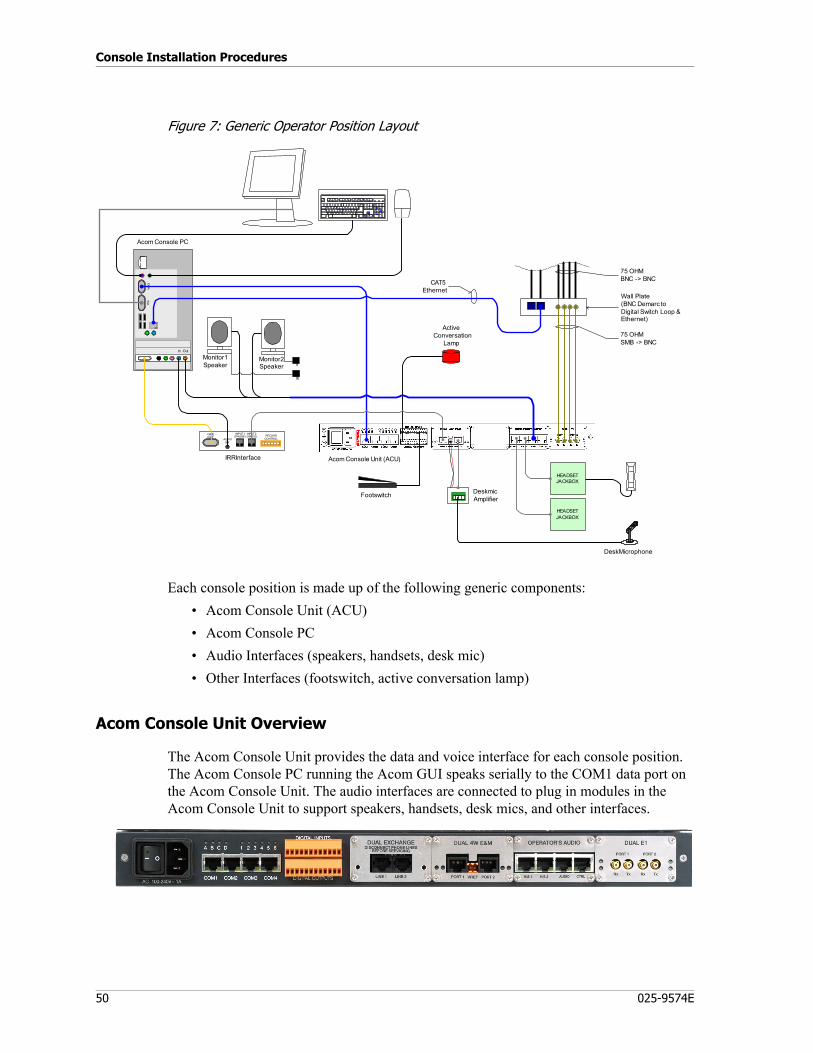
Console Installation Procedures
50 025-9574E
Figure 7: Generic Operator Position Layout
Each console position is made up of the following generic components:• Acom Console Unit (ACU)• Acom Console PC • Audio Interfaces (speakers, handsets, desk mic)• Other Interfaces (footswitch, active conversation lamp)
Acom Console Unit Overview
The Acom Console Unit provides the data and voice interface for each console position. The Acom Console PC running the Acom GUI speaks serially to the COM1 data port on the Acom Console Unit. The audio interfaces are connected to plug in modules in the Acom Console Unit to support speakers, handsets, desk mics, and other interfaces.
Esc F1 F2 F3 F4 F5
~`
!1 2 3 4 5 6 7
@ # $ % ^ &
Tab
F6 F7 F8 F9 F10 F11
8 9 0 - = \* ( ) _ + |
F12 P r in tS c re e n
S c ro llL o
c k
P a u
s e
I n s
e r t
H o
m e
P ag eUp
D e le
t e
E n
d
P a
g eD o wn H o
m e
N u
mL o c
k
L o c
k
C a p
sS c r o llL o c
k
P g Up
E nd
P g Dn
D e l
I
ns
E n
t er
N umL oc k
7 8 9
4 5 6
1 2 3
0
+
-*/
.C t
r l
S h i
f t/
?
"'
POI
K L :;
M
}
][
{
<,
>
.
UYTR
F G H J
NBVC
AltAlt
Q W E
A S D
Z X
C a p s
L o c k
S h i
f t
C t
r l
Monitor1Speaker
Acom Console Unit (ACU)
IOIO
I AVG
A
Acom Console PC
GAMEPORT
AUDIOOUT
INPUT 1(PHONE)
INPUT 2(RADIO)
1
RECORDCONTROL
IRR Interface
ActiveConversation
Lamp
HEADSETJACKBOX
HEADSETJACKBOX
Monitor2Speaker
75 OHMSMB -> BNC
75 OHMBNC -> BNC
Wall Plate(BNC Demarc toDigital Switch Loop &Ethernet)
CAT5Ethernet
In Out
Footswitch 1DeskmicAmplifier
Desk Microphone
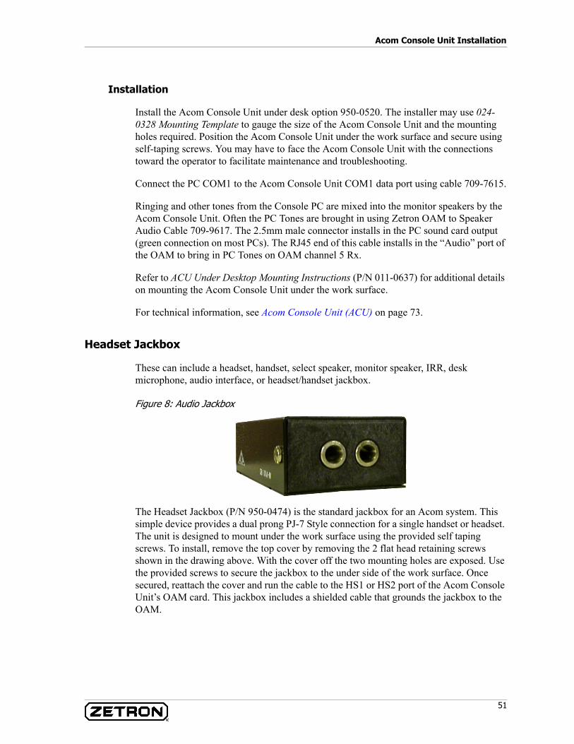
51
Acom Console Unit Installation
Installation
Install the Acom Console Unit under desk option 950-0520. The installer may use 024-0328 Mounting Template to gauge the size of the Acom Console Unit and the mounting holes required. Position the Acom Console Unit under the work surface and secure using self-taping screws. You may have to face the Acom Console Unit with the connections toward the operator to facilitate maintenance and troubleshooting.
Connect the PC COM1 to the Acom Console Unit COM1 data port using cable 709-7615.
Ringing and other tones from the Console PC are mixed into the monitor speakers by the Acom Console Unit. Often the PC Tones are brought in using Zetron OAM to Speaker Audio Cable 709-9617. The 2.5mm male connector installs in the PC sound card output (green connection on most PCs). The RJ45 end of this cable installs in the “Audio” port of the OAM to bring in PC Tones on OAM channel 5 Rx.
Refer to ACU Under Desktop Mounting Instructions (P/N 011-0637) for additional details on mounting the Acom Console Unit under the work surface.
For technical information, see Acom Console Unit (ACU) on page 73.
Headset Jackbox
These can include a headset, handset, select speaker, monitor speaker, IRR, desk microphone, audio interface, or headset/handset jackbox.
Figure 8: Audio Jackbox
The Headset Jackbox (P/N 950-0474) is the standard jackbox for an Acom system. This simple device provides a dual prong PJ-7 Style connection for a single handset or headset. The unit is designed to mount under the work surface using the provided self taping screws. To install, remove the top cover by removing the 2 flat head retaining screws shown in the drawing above. With the cover off the two mounting holes are exposed. Use the provided screws to secure the jackbox to the under side of the work surface. Once secured, reattach the cover and run the cable to the HS1 or HS2 port of the Acom Console Unit’s OAM card. This jackbox includes a shielded cable that grounds the jackbox to the OAM.
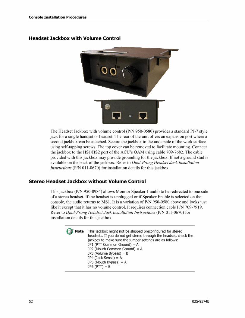
Console Installation Procedures
52 025-9574E
Headset Jackbox with Volume Control
The Headset Jackbox with volume control (P/N 950-0580) provides a standard PJ-7 style jack for a single handset or headset. The rear of the unit offers an expansion port where a second jackbox can be attached. Secure the jackbox to the underside of the work surface using self-tapping screws. The top cover can be removed to facilitate mounting. Connect the jackbox to the HS1/HS2 port of the ACU’s OAM using cable 709-7682. The cable provided with this jackbox may provide grounding for the jackbox. If not a ground stud is available on the back of the jackbox. Refer to Dual-Prong Headset Jack Installation Instructions (P/N 011-0670) for installation details for this jackbox.
Stereo Headset Jackbox without Volume Control
This jackbox (P/N 950-0984) allows Monitor Speaker 1 audio to be redirected to one side of a stereo headset. If the headset is unplugged or if Speaker Enable is selected on the console, the audio returns to MS1. It is a variation of P/N 950-0580 above and looks just like it except that it has no volume control. It requires connection cable P/N 709-7919. Refer to Dual-Prong Headset Jack Installation Instructions (P/N 011-0670) for installation details for this jackbox.
Note This jackbox might not be shipped preconfigured for stereo headsets. If you do not get stereo through the headset, check the jackbox to make sure the jumper settings are as follows:JP1 (PTT Common Ground) = AJP2 (Mouth Common Ground) = AJP3 (Volume Bypass) = BJP4 (Jack Sense) = AJP5 (Mouth Bypass) = AJP6 (PTT) = B

53
Acom Console Unit Installation
Telephone Radio Headset Interface
The Telephone Radio Headset Interface (TRHI) (P/N 950-9439) is an optional jackbox for integrating 3rd party phone systems with the Acom console. It provides a dual prong PJ-7 connector to support a single headset/handset. The TRHI has a physical volume control for the radio side (Acom) and the telephone side. The operator’s microphone is routed between the phone and radio by the TRHI using the PTT signal and Off-Hook signals.
Mount the TRHI to the underside of the work surface using self-tapping screws. The cover may be removed to facilitate its mounting. Connect Zetron cable 709-7629 between the DB9 connector on the rear of the TRHI and the HS1 or HS2 connector on the Acom Console Unit OAM. Connect the "PTT" wire to a Acom Console Unit digital output configured to activate on console PTT (see the Position Layout Diagram). Connect the "Hset" wire to a Acom Console Unit digital input configured as a "Headset Interface" that moves audio to the speaker when the phone is off-hook (see the Position Layout Diagram). Connect the wall bug power source and install a handset or headset. A ground connection should be made from the rear ground post of the TRHI to earth ground for ESD protection.
Refer to the Telephone Radio Headset Interface Product Manual (P/N 025-9553) for more information on the TRHI.
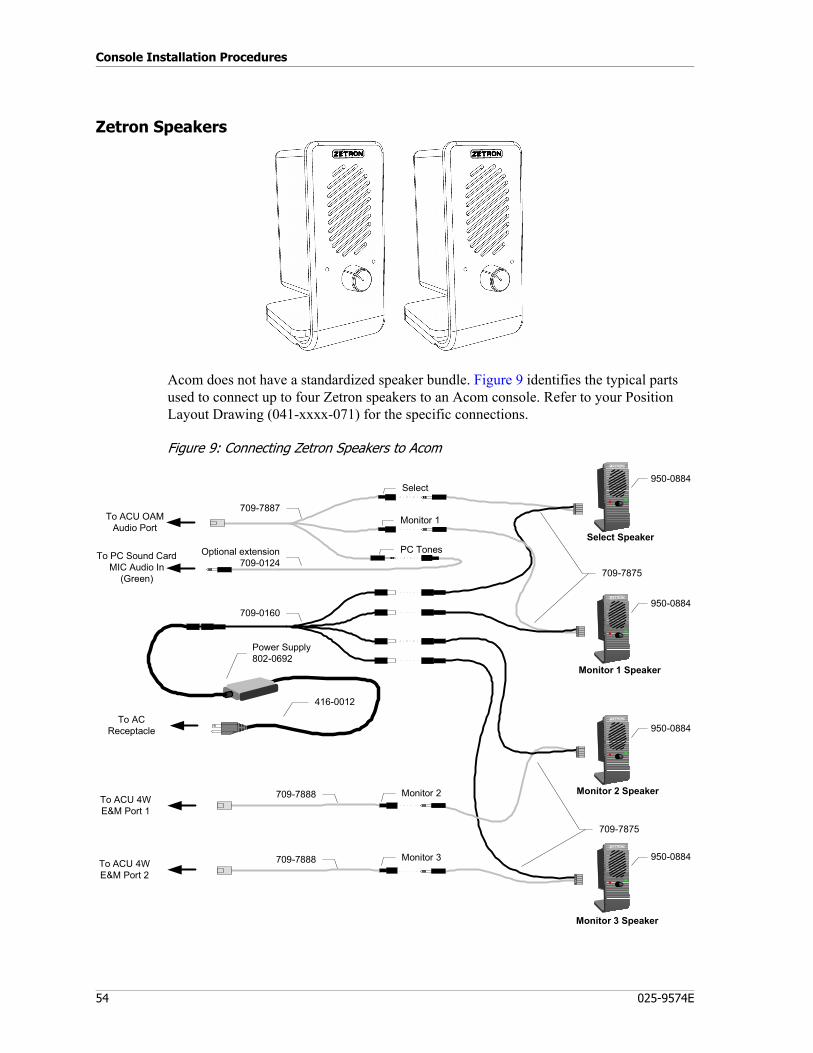
Console Installation Procedures
54 025-9574E
Zetron Speakers
Acom does not have a standardized speaker bundle. Figure 9 identifies the typical parts used to connect up to four Zetron speakers to an Acom console. Refer to your Position Layout Drawing (041-xxxx-071) for the specific connections.
Figure 9: Connecting Zetron Speakers to Acom
Power Supply 802-0692
709-7875
To AC Receptacle
Select Speaker
Monitor 1 Speaker
Optional extension709-0124
To PC Sound CardMIC Audio In
(Green)
709-7875
Monitor 2 Speaker
Monitor 3 Speaker
To ACU 4W E&M Port 1
To ACU 4W E&M Port 2
709-7887To ACU OAM
Audio Port
Select
Monitor 1
PC Tones
950-0884709-0160
709-7888
709-7888
416-0012
Monitor 2
Monitor 3
950-0884
950-0884
950-0884
55
Acom Console Unit Installation
Configuring the Select and Monitor 1 Speakers for Acom
♦ To configure OAM/Acom definitions
1. In IMS ACU, right-click on the Operator’s Audio module and select Acom Definitions. If there is more than one Operator’s Audio module, use the one connected to the speakers.
2. Click L/S 05 Right to open the channel 5 definition window.3. Set Connection Type to Console PC Tones.4. Assign Console Number (position) of the ACU.5. Set Interface to ACS (in) + HS Speaker (out).6. Set Tones To to Monitor Speaker 1.7. Adjust Speaker Volume Settings if needed.8. Click Save.9. Click L/S 06 Right to open the channel 6 definition window.10. Set Connection Type to Console Monitor.11. Assign Console Number (position) of the ACU.12. Set Monitor Speaker ID to 1.13. Set Primary Interface to Normal.14. Adjust Speaker Volume Settings if needed.15. Click Save, then Exit.
Consult the configuration guide or Project Engineer if you have any questions.
♦ To configure OAM/Gain settings
1. In IMS ACU, right-click the Operator’s Audio module and select Gain Setting. If there is more than one Operator’s Audio module, use the one connected to the speakers.
2. Based on testing and using a nominal -10dBm input, the following levels in the ACU will attain that approximate input level to the speaker. They may vary per system and will also depend on other system gain settings. To continue our example using channels 5 and 6:a. Set Channel 5 Gain TX to 7.0b. Set Channel 6 Gain TX to 7.0
3. Click Save.Consult the configuration guide or Project Engineer if you have any questions.
♦ To configure OAM/AGC settings
1. In IMS ACU, right-click on the Operator’s Audio module and select AGC setting. If there is more than one Operator’s Audio module, use the one connected to the speakers.

Console Installation Procedures
56 025-9574E
2. Ensure that both the Select and Monitor channels do not use AGC by clearing their respective Tx Mode Enabled check boxes. To continue our example, channels 5 and 6 should have the Tx Mode Enabled check boxes cleared.
3. Click Save.Consult the Project Engineer if specific Gain and AGC settings are required for specific headset or speakers.
Configuring Monitor 2 and 3 Speakers for Acom
♦ Dual 4W E&M/Acom Definitions
1. In IMS ACU, right-click on the Dual 4W E&M module and select Acom Definitions. If there is more than one Dual 4W E&M module, use the one connected to the speakers.
2. Click Port 01 and assign the Connection Type as Console Monitor.3. Assign Console Number (position) of the ACU.4. Set Monitor Speaker ID to 2.5. Click Save.6. Click Port 02 and assign the Connection Type as Console Monitor.7. Assign Console Number (position) of the ACU.8. Set Monitor Speaker ID to 3.9. Click Save.
Consult the configuration guide or Project Engineer if you have any questions.
♦ Dual 4w Card-Gain Settings
1. In IMS ACU, right click on the Dual 4W E&M module and select Gain Setting. If there is more than one Dual 4W E&M module, use the one connected to the speakers.
2. Set Gain RX to 0 and Gain TX to -1 for both channels on the Dual 4w card.3. Click Save.
Consult the configuration guide or Project Engineer if you have any questions.
♦ Dual 4w AGC Settings
1. The AGC Settings can be accessed by right clicking on the Dual 4W E&M module and selecting AGC Setting. If there is more than one Dual 4W E&M module, use the one connected to the speakers.
2. Ensure that both channels do not use AGC by clearing the Tx Mode Enabled check boxes.
3. Click Save.Consult the Project Engineer if specific AGC settings are required for specific speakers.

57
Acom Console Unit Installation
Deskmic Option
Zetron Desktop Microphone
The Zetron Desktop Microphone (901-9660 and 901-9661, pictured below) is provided with its own installation manual. For more information, see Zetron Desktop Microphone Manual (P/N 025-9589).
Legacy Desktop Microphone
The desk mic option (950-0646 and 802-0154 w/ PDN 214) includes an in-line AGC amplifier for use with a dual 4-Wire E&M Module. This option provides the required amplification for the deskmic 802-0154 to operate with the 4-Wire E&M Module.
♦ To install the legacy deskmic option:
1. Screw down the leads from the desk mic to the Desk Mic Amplifier J1 terminals.• Pin1 – Ground• Pin2 – Mic
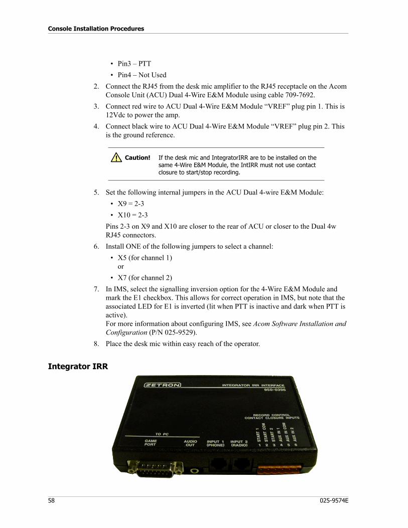
Console Installation Procedures
58 025-9574E
• Pin3 – PTT• Pin4 – Not Used
2. Connect the RJ45 from the desk mic amplifier to the RJ45 receptacle on the Acom Console Unit (ACU) Dual 4-Wire E&M Module using cable 709-7692.
3. Connect red wire to ACU Dual 4-Wire E&M Module “VREF” plug pin 1. This is 12Vdc to power the amp.
4. Connect black wire to ACU Dual 4-Wire E&M Module “VREF” plug pin 2. This is the ground reference.
5. Set the following internal jumpers in the ACU Dual 4-wire E&M Module:• X9 = 2-3• X10 = 2-3
Pins 2-3 on X9 and X10 are closer to the rear of ACU or closer to the Dual 4w RJ45 connectors.
6. Install ONE of the following jumpers to select a channel:• X5 (for channel 1)
or• X7 (for channel 2)
7. In IMS, select the signalling inversion option for the 4-Wire E&M Module and mark the E1 checkbox. This allows for correct operation in IMS, but note that the associated LED for E1 is inverted (lit when PTT is inactive and dark when PTT is active).For more information about configuring IMS, see Acom Software Installation and Configuration (P/N 025-9529).
8. Place the desk mic within easy reach of the operator.
Integrator IRR
Caution! If the desk mic and IntegratorIRR are to be installed on the same 4-Wire E&M Module, the IntIRR must not use contact closure to start/stop recording.
!
59
Acom Console Unit Installation
This section only contains the information about Integrator IRR that is related to Acom. For more complete information about Integrator IRR, refer to the manual Integrator IRR Product Manual (P/N 025-9496).
The Integrator IRR is a software-based instant recall recorder used to save and playback position audio by the operator. When used with an Acom system it can record phone calls and radio transmissions to the PC hard drive.
Requirements• Integrator IRR (includes IRR module, Game port cable, PC audio cable, IRR
Manual 025-9496, and IRR software, Soundblaster Live sound card)• Acom Console Unit equipped with E&M 4-Wire E&M Module• Acom Console Unit to IRR cable 709-7639• Zetron User Management Software (UMS)• One free, full-height PCI slot in the console PC (suitable for a SoundBlaster Live
sound card)
Theory of Operation
The IRR will record transmit and receive audio from the Acom console. The IRR will record under any of the following conditions:
• A phone line is selected.• A selected radio channel (radio base) has CD or VOX activity.• A radio channel is keyed by the operator.
The IRR can use contact closure, software control, or VOX to trigger the start/stop of a recording. Only one application can command the IntIRR with software control at a time, so we recommend using software control unless you are installing the Acom console in conjunction with a Zetron M3200 phone.
Software Control
The Console PC will use software commands to control the IRR application when activated with the following setting in the “AcomConsole.ini” file:
[IMS Terminal]EnableIRR=True
Contact Closure
The M1 lead from the Dual 4-wire E&M Module goes active to signal the PC to begin recording. The IRR box provides a ground reference to the M1 lead of the E&M card. Under idle conditions this ground is passed out the +VREF (pin 1-left) of the center orange connector X2 on the E&M card. When recording should begin, the ground is removed from the +VREF lead which signals the PC to begin recording.

Console Installation Procedures
60 025-9574E
VOX Recording
The IRR has the ability to record based on the presence of audio alone. This option should be used as a last resort as it does not provide the finite control of recording that the other two options do.
SoundBlaster Installation
IntegratorIRR requires a SoundBlaster Live card.
♦ To install the SoundBlaster card and drivers:
1. Shut down the computer.2. Insert the "SoundBlaster Live! Value" card into an empty slot in the computer.3. Restart the computer.4. The Found New Hardware wizard screen should appear. Do not insert the
SoundBlaster CD at this time.
5. Follow the wizard's instructions to search for a suitable driver for the new device. Set the search locations parameter to the CD drive.
6. Insert the Creative SoundBlaster Installation CD into the CD drive. When the SoundBlaster installation program starts, click Cancel.
7. Follow the rest of the Add New Hardware wizard instructions to finish installing the driver found on the CD.
8. When the wizard is finished, go to the Windows Start menu and select Settings, Control Panel, Sounds and Multimedia.
9. Click on the Audio tab.10. From the item lists, select the item corresponding to Creative SB Live! (or Emul
10Kx Audio[E000]) for both Sound Playback and Sound Recording.11. Mark the Use only preferred devices checkbox.12. Click OK.13. Restart the computer.
SoundBlaster Configuration
♦ To configure the sound card:
1. Click START, Settings, Control Panel to open the Windows Control Panel.2. Open Sounds and Multimedia in the Control Panel. Select the Audio tab and set
Playback and Recording to use the SoundBlaster Live card.
Caution! It is very important that you use the Windows Add New Hardware feature to install the driver for this sound card. Do not use the installation program that comes on the SoundBlaster CD.
!
61
Acom Console Unit Installation
3. Select Use preferred devices only.4. Click OK on the Sounds and Multimedia panel to save your changes.5. From the Windows Control Panel, open Gaming Options. Add a new controller of
type 2-axis 2-button joystick. This is required for contact closure operation to start recording.
6. Click OK to save your changes.
Hardware Installation
♦ To install IntegratorIRR:
1. Install cable 709-7728 "Software/VOX Control Cable" or 709-7639 "Contact Control Cable" between one of the dual 4-wire ports on the Acom Console Unit and "Input 2 (Radio)" on the IRR module.
2. Connect the 2.5mm audio cable provided with the IRR between the IRR Hardware Module jack and the Line Input (Black port) of the Soundblaster Live soundcard.
3. If using contact closure to trigger the start and stop of recording, connect the game port cable provided with the IRR between the IRR module DB15 connector and the Soundblaster Live game port.
4. Use the provided Velcro to secure the IRR module to the side or top of the Console PC.
5. Connect the IRR Hardware Module "Input 1 (Phone)" to the 3rd party phone system if applicable.
E&M 4-Wire Module Installation
If the Acom Console Unit did not come with the required E&M Module pre-installed, install the 4-Wire E&M Module now. See Dual 4W E&M Module on page 89.
Configuring Acom for Integrator IRR
♦ To configure Acom for Integrator IRR:
1. Connect to the Acom Console Unit using IMS ACU.2. Right-click on the 4-Wire E&M Module and choose Acom Definitions.3. Click Channel 1 and configure it for Voice Logger/IRR.4. Set the console number to match the position number and click Save.
Warning! If the desk mic and IntegratorIRR are to be installed on the same 4-Wire E&M Module, the IntegratorIRR must not use contact closure to start/stop recording.
STOP
Note Use of Integrator IRR contact closure recording is incompatible with the Acom Deskmic if used on the same Dual 4 wire module. The Deskmic may be used with software or VOX controlled IRR.

Console Installation Procedures
62 025-9574E
You may configure only one “Voice Logger” and one “IRR” per console number.5. Right-click on the 4-Wire E&M Module and choose Signalling Inversion. Invert
the M1 signal for Channel 1 only and click Save.The M1 lead is used to trigger the recording of Acom audio.
6. Right-click on the 4-Wire E&M Module and choose Gain. Set the transmit gain to +6dB for Channel 1.
7. From the IMS menu click File, Update to NVRam to save your changes to flash.8. Reset to console from the Tools, Reset menu in IMS.9. Close IMS ACU.
Integrator Software Installation
♦ To install Integrator software:
1. Insert the Integrator IRR Install CD into the PC CD-ROM drive.2. The installer should automatically start; if it does not, click START, Run, and type
“D:\Setup” where D is the drive letter of your CD-ROM.3. Install UMS Client on the local machine. This will require a reboot. Leave the CD
in during the reboot and the second phase of the installation will begin automatically when Windows restarts.The User Management System (UMS) controls access to Zetron applications.
4. Install IntegratorIRR from the CD. Follow the installer’s prompts to complete the installation of Integrator IRR.
5. After installation, copy the .LIC file provided by Zetron into the “C:\Program Files\Zetron\Integrator IRR\” folder. If you don’t have a license file (*.LIC) yet, contact Zetron tech support.
6. Run the UMS shortcut from either the start menu or desktop; it will start in “Off-Line” mode.
7. Log into UMS using the name “z_admin” and no password (blank).8. Run ZAM and activate “On-Line” mode to connect with the UMS Server.
Configure your users with the permission to execute Integrator IRR. For additional information, see the UMS manual (P/N 025-9516).
Configuring Integrator IRR
♦ To configure Integrator IRR:
1. Double click on the IRR icon to start the program.
Note If desired, the IRR may be installed without the UMS requirement. There is a registry patch on the installation CD that will allow it to be run without requiring a UMS logon. Without this patch, the operator will be required to log into UMS prior to running Integrator IRR.
63
Acom Console Unit Installation
2. Once the program has started, click Edit, Options.
3. In the Options box of the Audio Settings tab, click Input 2, Sources Alias, and type “Acom”. Saved recordings will be labeled with their source.
4. Click the Record Control tab, then Input 2.5. Set Input Gain to +6 dB.6. Select AGC Enabled.7. Select the type of recording control you wish (software control is recommended).8. Click Apply, then OK.9. Select the Storage tab.10. Set Disk Allocation to a reasonable size (500MB).11. Set Warning Threshold to “10%”.12. Click Browse and navigate to “C:\Program Files\Zetron\Integrator IRR”13. Add “\Recordings” to the end of the path and accept the popup that will appear.
Verify that Storage Location reflects “C:\Program Files\Zetron\Integrator IRR\Messages”
14. Click OK to save the changes.
Configure Acom Console to use IRR
♦ To configure the AcomConsole.ini file for Integrator IRR:
1. Browse to the folder for the Acom console software. This may be “C:\Program Files\Zetron\ACS” or “C:\Program Files\ACS”.
2. Open AcomConsole.ini using Notepad or other text editor.3. Search for the section called [ACS].4. Add/modify the following values in the [ACS] section to launch IntIRR on login
and use software control to control recording:EnableIRR=TrueEnableIRRSoftwareControl=TrueIRRChannelAlias=Acom
5. If you will be using UMS to control permissions for IntIRR, add/modify the following value in the [ACS] section:
EnableUMS=True
6. Save the file and start the console software from the Windows Start menu.
Note The options menu is controlled by the user’s UMS permissions.
Note If you have not licensed the software, you may get a warning window that this demo will expire in 10 days. If the warning window appears, contact Zetron tech support. The first time the program runs it will warn you to configure your storage settings, click OK to proceed.
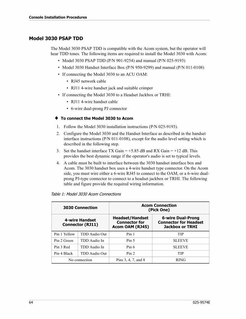
Console Installation Procedures
64 025-9574E
Model 3030 PSAP TDD
The Model 3030 PSAP TDD is compatible with the Acom system, but the operator will hear TDD tones. The following items are required to install the Model 3030 with Acom:
• Model 3030 PSAP TDD (P/N 901-9254) and manual (P/N 025-9193)• Model 3030 Handset Interface Box (P/N 950-9299) and manual (P/N 011-0108)• If connecting the Model 3030 to an ACU OAM:
• RJ45 network cable• RJ11 4-wire handset jack and suitable crimper
• If connecting the Model 3030 to a Headset Jackbox or TRHI:• RJ11 4-wire handset cable• 6-wire dual-prong PJ connector
♦ To connect the Model 3030 to Acom
1. Follow the Model 3030 installation instructions (P/N 025-9193).2. Configure the Model 3030 and the Handset Interface as described in the handset
interface instructions (P/N 011-0108), except for the audio level setting which is described in the following step.
3. Set the handset interface TX Gain = +5.85 dB and RX Gain = +12 dB. This provides the best dynamic range if the operator's audio is set to typical levels.
4. A cable must be built to interface between the 3030 handset interface box and Acom. The 3030 handset box uses a 4-wire handset type connector. On the Acom side, you must wire either a 6-wire RJ45 to connect to the OAM, or a 6-wire dual-prong PJ-type connector to connect to a headset jackbox or TRHI. The following table and figure provide the required wiring information.
Table 1: Model 3030 Acom Connections
3030 Connection Acom Connection(Pick One)
4-wire Handset Connector (RJ11)
Headset/Handset Connector for
Acom OAM (RJ45)
6-wire Dual-Prong Connector for Headset
Jackbox or TRHI
Pin 1 Yellow TDD Audio Out Pin 1 TIPPin 2 Green TDD Audio In Pin 5 SLEEVEPin 3 Red TDD Audio In Pin 6 SLEEVEPin 4 Black TDD Audio Out Pin 2 TIP
No connection Pins 3, 4, 7, and 8 RING
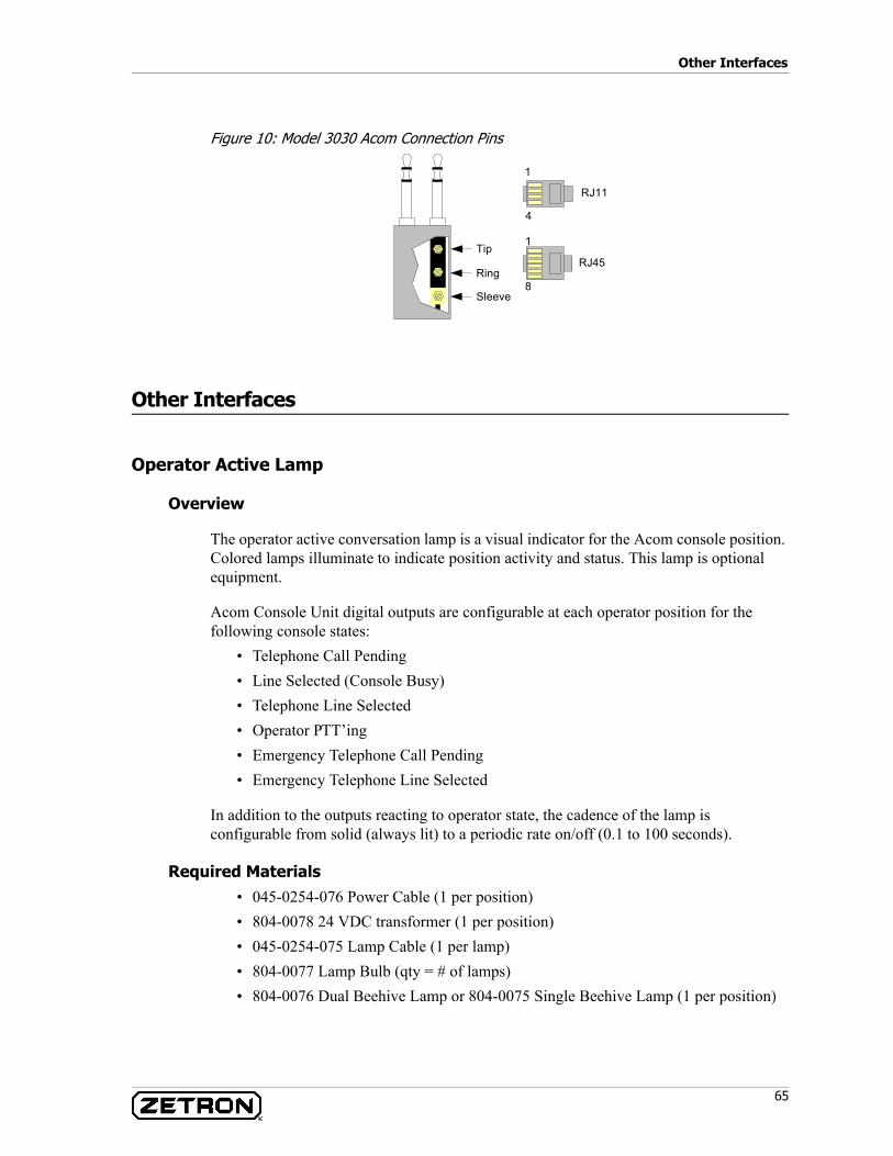
65
Other Interfaces
Figure 10: Model 3030 Acom Connection Pins
Other Interfaces
Operator Active Lamp
Overview
The operator active conversation lamp is a visual indicator for the Acom console position. Colored lamps illuminate to indicate position activity and status. This lamp is optional equipment.
Acom Console Unit digital outputs are configurable at each operator position for the following console states:
• Telephone Call Pending• Line Selected (Console Busy)• Telephone Line Selected• Operator PTT’ing• Emergency Telephone Call Pending • Emergency Telephone Line Selected
In addition to the outputs reacting to operator state, the cadence of the lamp is configurable from solid (always lit) to a periodic rate on/off (0.1 to 100 seconds).
Required Materials• 045-0254-076 Power Cable (1 per position)• 804-0078 24 VDC transformer (1 per position)• 045-0254-075 Lamp Cable (1 per lamp)• 804-0077 Lamp Bulb (qty = # of lamps)• 804-0076 Dual Beehive Lamp or 804-0075 Single Beehive Lamp (1 per position)
1
4
RJ11
1
8
RJ45Tip
Ring
Sleeve
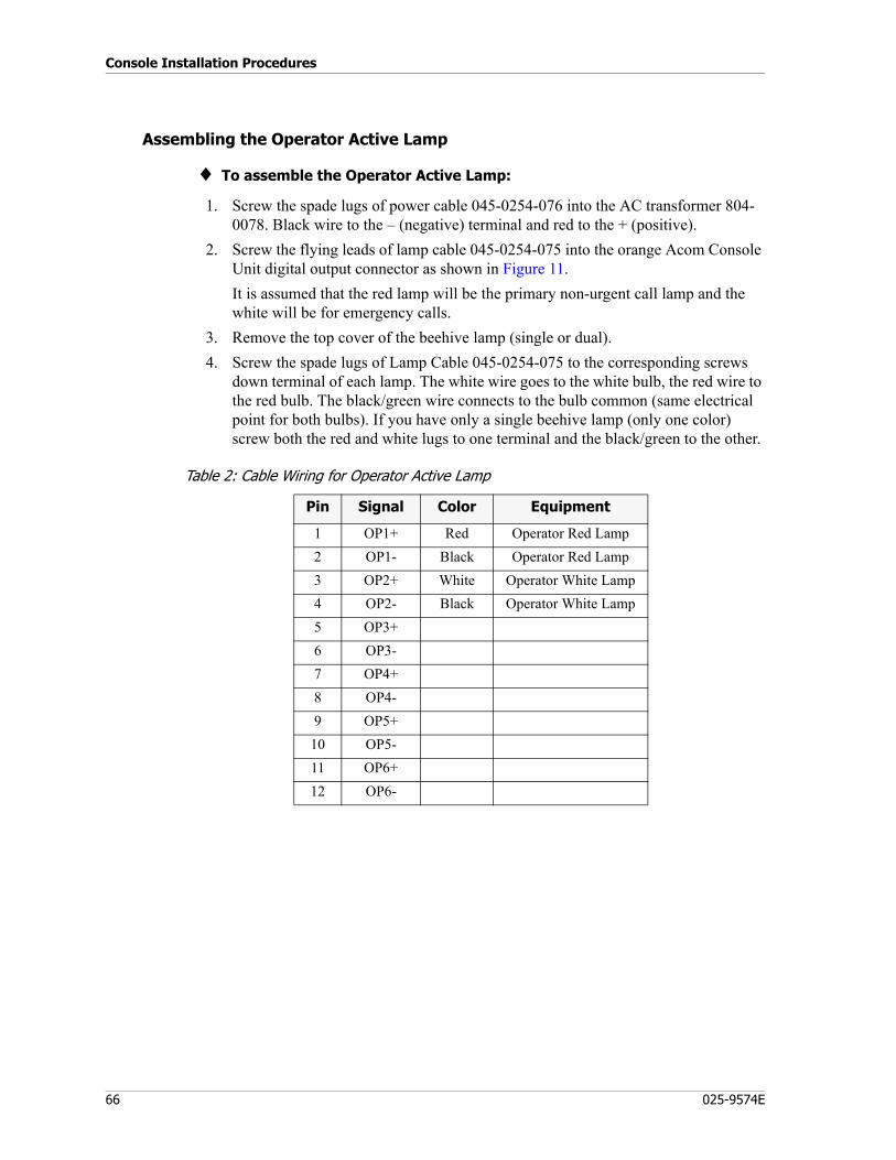
Console Installation Procedures
66 025-9574E
Assembling the Operator Active Lamp
♦ To assemble the Operator Active Lamp:
1. Screw the spade lugs of power cable 045-0254-076 into the AC transformer 804-0078. Black wire to the – (negative) terminal and red to the + (positive).
2. Screw the flying leads of lamp cable 045-0254-075 into the orange Acom Console Unit digital output connector as shown in Figure 11.It is assumed that the red lamp will be the primary non-urgent call lamp and the white will be for emergency calls.
3. Remove the top cover of the beehive lamp (single or dual).4. Screw the spade lugs of Lamp Cable 045-0254-075 to the corresponding screws
down terminal of each lamp. The white wire goes to the white bulb, the red wire to the red bulb. The black/green wire connects to the bulb common (same electrical point for both bulbs). If you have only a single beehive lamp (only one color) screw both the red and white lugs to one terminal and the black/green to the other.
Table 2: Cable Wiring for Operator Active Lamp
Pin Signal Color Equipment
1 OP1+ Red Operator Red Lamp2 OP1- Black Operator Red Lamp3 OP2+ White Operator White Lamp4 OP2- Black Operator White Lamp5 OP3+6 OP3-7 OP4+8 OP4-9 OP5+
10 OP5-11 OP6+12 OP6-
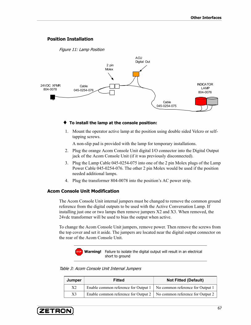
67
Other Interfaces
Position Installation
Figure 11: Lamp Position
♦ To install the lamp at the console position:
1. Mount the operator active lamp at the position using double sided Velcro or self-tapping screws.A non-slip pad is provided with the lamp for temporary installations.
2. Plug the orange Acom Console Unit digital I/O connector into the Digital Output jack of the Acom Console Unit (if it was previously disconnected).
3. Plug the Lamp Cable 045-0254-075 into one of the 2 pin Molex plugs of the Lamp Power Cable 045-0254-076. The other 2 pin Molex would be used if the position needed additional lamps.
4. Plug the transformer 804-0078 into the position’s AC power strip.
Acom Console Unit Modification
The Acom Console Unit internal jumpers must be changed to remove the common ground reference from the digital outputs to be used with the Active Conversation Lamp. If installing just one or two lamps then remove jumpers X2 and X3. When removed, the 24vdc transformer will be used to bias the output when active.
To change the Acom Console Unit jumpers, remove power. Then remove the screws from the top cover and set it aside. The jumpers are located near the digital output connector on the rear of the Acom Console Unit.
Table 3: Acom Console Unit Internal Jumpers
INDICATORLAMP
804-0076
24VDC XFMR804-0078
Cable045-0254-075
Cable045-0254-076
2 pinMolex
ACUDigital Out
Warning! Failure to isolate the digital output will result in an electrical short to ground
Jumper Fitted Not Fitted (Default)
X2 Enable common reference for Output 1 No common reference for Output 1X3 Enable common reference for Output 2 No common reference for Output 2
STOP
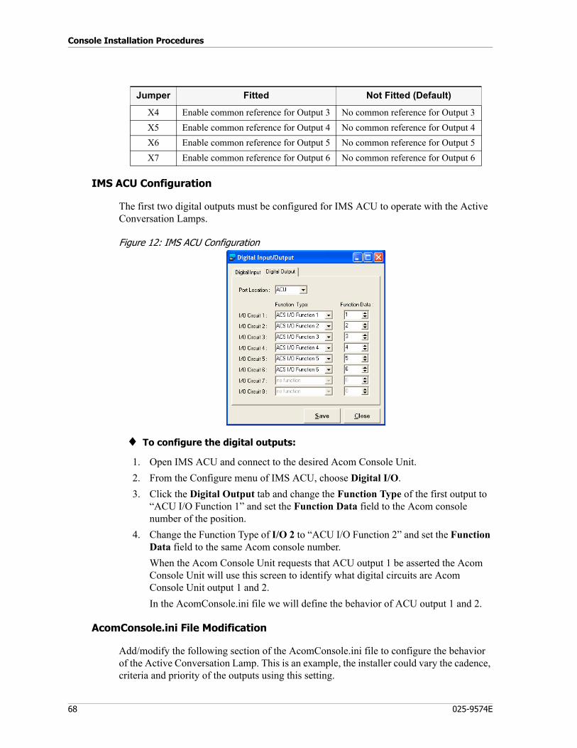
Console Installation Procedures
68 025-9574E
IMS ACU Configuration
The first two digital outputs must be configured for IMS ACU to operate with the Active Conversation Lamps.
Figure 12: IMS ACU Configuration
♦ To configure the digital outputs:
1. Open IMS ACU and connect to the desired Acom Console Unit.2. From the Configure menu of IMS ACU, choose Digital I/O.3. Click the Digital Output tab and change the Function Type of the first output to
“ACU I/O Function 1” and set the Function Data field to the Acom console number of the position.
4. Change the Function Type of I/O 2 to “ACU I/O Function 2” and set the Function Data field to the same Acom console number.When the Acom Console Unit requests that ACU output 1 be asserted the Acom Console Unit will use this screen to identify what digital circuits are Acom Console Unit output 1 and 2.In the AcomConsole.ini file we will define the behavior of ACU output 1 and 2.
AcomConsole.ini File Modification
Add/modify the following section of the AcomConsole.ini file to configure the behavior of the Active Conversation Lamp. This is an example, the installer could vary the cadence, criteria and priority of the outputs using this setting.
X4 Enable common reference for Output 3 No common reference for Output 3X5 Enable common reference for Output 4 No common reference for Output 4X6 Enable common reference for Output 5 No common reference for Output 5X7 Enable common reference for Output 6 No common reference for Output 6
Jumper Fitted Not Fitted (Default)
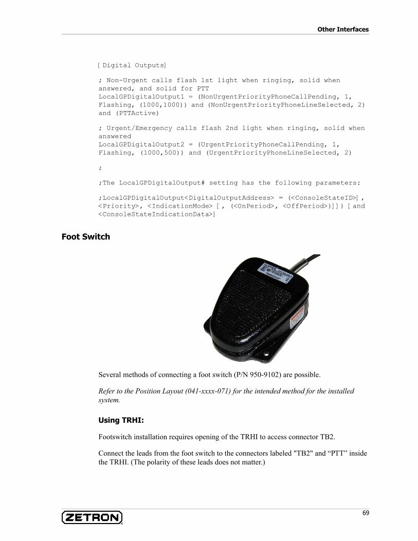
69
Other Interfaces
[Digital Outputs]
; Non-Urgent calls flash 1st light when ringing, solid when answered, and solid for PTTLocalGPDigitalOutput1 = (NonUrgentPriorityPhoneCallPending, 1, Flashing, (1000,1000)) and (NonUrgentPriorityPhoneLineSelected, 2) and (PTTActive)
; Urgent/Emergency calls flash 2nd light when ringing, solid when answeredLocalGPDigitalOutput2 = (UrgentPriorityPhoneCallPending, 1, Flashing, (1000,500)) and (UrgentPriorityPhoneLineSelected, 2)
;
;The LocalGPDigitalOutput# setting has the following parameters:
;LocalGPDigitalOutput<DigitalOutputAddress> = (<ConsoleStateID>[, <Priority>, <IndicationMode> [, (<OnPeriod>, <OffPeriod>)]]) [and <ConsoleStateIndicationData>]
Foot Switch
Several methods of connecting a foot switch (P/N 950-9102) are possible.
Refer to the Position Layout (041-xxxx-071) for the intended method for the installed system.
Using TRHI:
Footswitch installation requires opening of the TRHI to access connector TB2.
Connect the leads from the foot switch to the connectors labeled "TB2" and “PTT” inside the TRHI. (The polarity of these leads does not matter.)
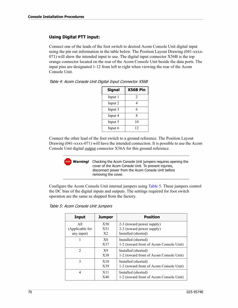
Console Installation Procedures
70 025-9574E
Using Digital PTT input:
Connect one of the leads of the foot switch to desired Acom Console Unit digital input using the pin out information in the table below. The Position Layout Drawing (041-xxxx-071) will show the intended input to use. The digital input connector X56B is the top orange connector located on the rear of the Acom Console Unit beside the data ports. The input pins are designated 1-12 from left to right when viewing the rear of the Acom Console Unit.
Table 4: Acom Console Unit Digital Input Connector X56B
Connect the other lead of the foot switch to a ground reference. The Position Layout Drawing (041-xxxx-071) will have the intended connection. It is possible to use the Acom Console Unit digital output connector X56A for this ground reference.
Configure the Acom Console Unit internal jumpers using Table 5. These jumpers control the DC bias of the digital inputs and outputs. The settings required for foot switch operation are the same as shipped from the factory.
Table 5: Acom Console Unit Jumpers
Signal X56B Pin
Input 1 2Input 2 4Input 3 6Input 4 8Input 5 10Input 6 12
Warning! Checking the Acom Console Unit jumpers requires opening the cover of the Acom Console Unit. To prevent injuries, disconnect power from the Acom Console Unit before removing the cover.
Input Jumper Position
All(Applicable for
any input)
X50X51X2
2-3 (toward power supply)2-3 (toward power supply)Installed (shorted)
1 X8X37
Installed (shorted)1-2 (toward front of Acom Console Unit)
2 X9X38
Installed (shorted)1-2 (toward front of Acom Console Unit)
3 X10X39
Installed (shorted)1-2 (toward front of Acom Console Unit)
4 X11X40
Installed (shorted)1-2 (toward front of Acom Console Unit)
STOP

71
Console Quick Checkout Instructions
E1 Digital Interfaces
See Console Loop Installation on page 40.
Console Quick Checkout Instructions
This section describes a quick checkout of an operator position to be done after the replacement/installation of any hardware. The purpose is to ensure the console audio interfaces are properly connected and functional.
♦ To check a console:
1. Start the Acom Console Software and log on.a. Verify the Acom Console Software starts up without errors. If it does not
communicate, the serial port may not be installed correctly.b. Verify the console number is correct as per the Network Diagram (041-xxxx-
062).c. Verify that all radio, phone, and digital IO buttons appear active (not grayed
out).2. Install a handset into the left Zetron jackbox.
a. Verify that Acom Console Software “Mode:” shows H-Set. If it does not, check that its connected to an HS port.
3. Move the handset to the right Zetron jackbox.a. Verify that the Acom Console Software “Mode:” shows H-Set. If it does not,
check that its connected to an HS port.4. Test the various PTT sources.
a. Use the Handset/Headset inline PTT to key a radio channel, verify the PTT button changes color and the line text turns yellow. Repeat for the second jackbox.
b. Use the footswitch (if installed) to key a radio channel, verify the PTT button changes color and the line text turns yellow.
c. Use the desk mic (if installed) to key a radio channel, verify the PTT button changes color and the line text turns yellow.
5. Select a phone line.
5 X12X41
Installed (shorted)1-2 (toward front of Acom Console Unit)
6 X13X42
Installed (shorted)1-2 (toward front of Acom Console Unit)
Input Jumper Position
Console Installation Procedures
72 025-9574E
a. Verify you can hear a dialtone and that you can dial.b. Verify that Integrator IRR (if installed) has recorded the phone call.
6. Place an active radio channel into monitor speaker 1. If there is no activity, generate a test tone for that line as an audio source.a. Verify that the test tone can be heard in the left speaker of this position. If it
appears in the right the connections are swapped at the rear of the PC.7. Place an active radio channel into monitor speaker 2.
a. Verify the test tone can be heard in the right speaker.8. Select an active radio channel.
a. Verify the audio can be heard in the handset/headset.b. Verify that Integrator IRR (if installed) has recorded the phone call.
9. Clear all selected lines and monitors from the console and log off the Acom Console Software.
This concludes the installation procedures for the “front room” (console) equipment. The remainder of this document provides detailed reference information for console equipment.
Acom Console Unit (ACU)
73
Hardware Components
This chapter provides reference material for various hardware components:
Acom Console Unit (ACU) on page 73Acom Line Subracks on page 92Acom DS3 Switch (ADS) Subrack on page 102Changeover Subrack on page 105
For cards, see Acom Card Reference on page 111.
Acom Console Unit (ACU)
This section describes the Acom Console Unit (ACU) and how to connect the Acom Console Units to the other interfacing hardware. After the Acom Console Unit is connected, it is configured using the IMS ACU software. See Acom Software Installation and Configuration (P/N 025-9529) for more information.)
General
The ACU provides the data and voice interface for each console position. The Acom Console PC running the Acom Console Software communicates serially to the COM1 data port on the ACU. The audio interfaces are connected to plug in modules in the ACU to support speakers, handsets, desk mics, and other interfaces.
The ACU is a 1U component that provides audio and data interfaces between the operator position and the CCE using an E1 cable. It provides a serial data interface for the System Console. In addition, it also provides speaker, handset, and microphone interfaces for the operator position.
Note The Acom Console Unit was formerly named Operator Console Unit (OCU) and Digital Switch.
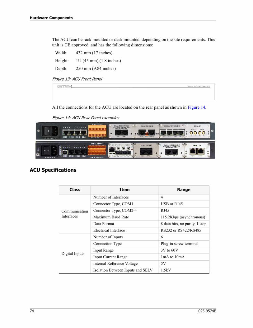
Hardware Components
74 025-9574E
The ACU can be rack mounted or desk mounted, depending on the site requirements. This unit is CE approved, and has the following dimensions:
Width: 432 mm (17 inches)
Height: 1U (45 mm) (1.8 inches)
Depth: 250 mm (9.84 inches)
Figure 13: ACU Front Panel
All the connections for the ACU are located on the rear panel as shown in Figure 14.
Figure 14: ACU Rear Panel examples
ACU Specifications
Class Item Range
CommunicationInterfaces
Number of Interfaces 4Connector Type, COM1 USB or RJ45Connector Type, COM2-4 RJ45Maximum Baud Rate 115.2Kbps (asynchronous)Data Format 8 data bits, no parity, 1 stopElectrical Interface RS232 or RS422/RS485
Digital Inputs
Number of Inputs 6Connection Type Plug-in screw terminalInput Range 3V to 60VInput Current Range 1mA to 10mAInternal Reference Voltage 5VIsolation Between Inputs and SELV 1.5kV

75
Acom Console Unit (ACU)
ACU Power Requirements
Digital Outputs
Number of Outputs 6Connection Type Plug-in screw terminalMaximum Switched Voltage 60VdcMaximum Output Current 100mAInternal Reference Voltage 0V (ground)Isolation Between Outputs and SELV 1.5kV
EnvironmentOperating Temperature 0 to 60 degrees CStorage Temperature -10 to 70 degrees CHumidity 95% RH at 40 degrees C
Electrical
Power from AC Mains 85 to 260 Vac47 to 63 Hz96 VA
Maximum +5V power consumption 1AMaximum +12V power consumption 1.2A
Class Item Range
AC Unit 12/24VDC Unit 48VDC Unit
Input Voltage Range 85 to 260 Vrms 9 to 36 V 18 to 60 VMax Input Current 0.4 A (240V), 0.6 A (115V) 2.1 A 1.1 AInput Power 35 W 50 W 50 WFrequency 47 to 63 Hz
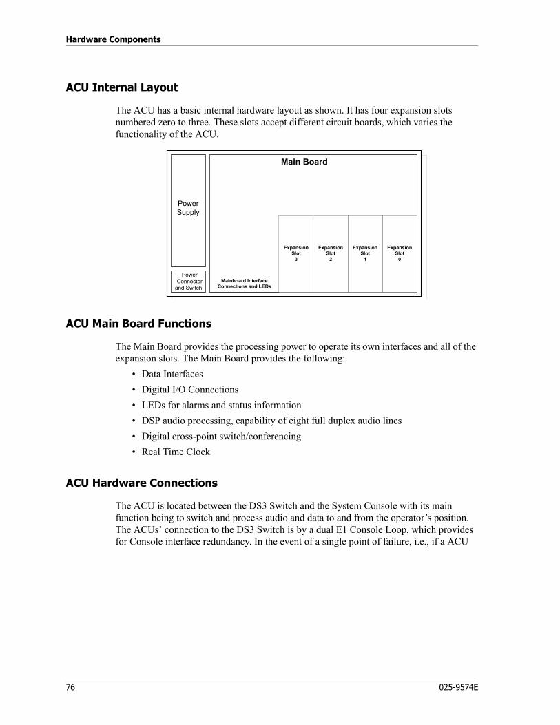
Hardware Components
76 025-9574E
ACU Internal Layout
The ACU has a basic internal hardware layout as shown. It has four expansion slots numbered zero to three. These slots accept different circuit boards, which varies the functionality of the ACU.
ACU Main Board Functions
The Main Board provides the processing power to operate its own interfaces and all of the expansion slots. The Main Board provides the following:
• Data Interfaces• Digital I/O Connections• LEDs for alarms and status information• DSP audio processing, capability of eight full duplex audio lines• Digital cross-point switch/conferencing• Real Time Clock
ACU Hardware Connections
The ACU is located between the DS3 Switch and the System Console with its main function being to switch and process audio and data to and from the operator’s position. The ACUs’ connection to the DS3 Switch is by a dual E1 Console Loop, which provides for Console interface redundancy. In the event of a single point of failure, i.e., if a ACU
Main Board
ExpansionSlot
0
ExpansionSlot
1
ExpansionSlot
2
ExpansionSlot
3
Mainboard InterfaceConnections and LEDs
PowerConnector
and Switch
PowerSupply

77
Acom Console Unit (ACU)
becomes inoperable or the Console Loop fails, the other Consoles in the chain still maintain a connection path to the DS3 Switch.
ACU External Interfaces
The following illustration shows the ACU’s external interfaces, however, the physical locations for the connectors are all on the ACU’s rear panel.
AcomConsole Unit
(1)
E1Links
System Console
Voice Voice
System Console
n = 2 to 8
E1Links
(n)
DS3 Loop
P1 P2 P1 P2
Port A Port B Port BPort A
AcomConsole Unit
Acom DS3 Switch (ADS)
Acom DS3 Switch (ADS)
Acom ConsoleUnit (ACU)
H/S1H/S2
AUDIO
PC
Tone
s
DATA
COM 1
G703
DS3 Switch
Next ACU
G703Speaker(Left)
Speaker(Right)
OperatorAudioModule
DualE1
Module
Acom Console PC
PCSoundCard
Handset
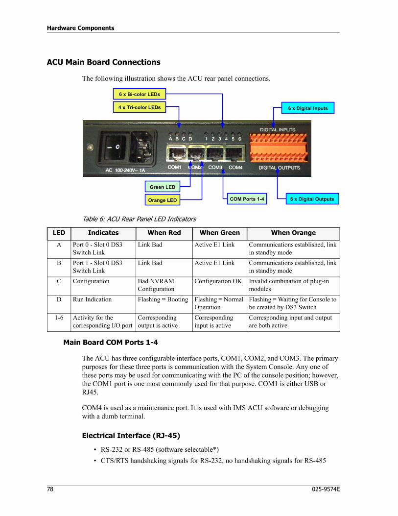
Hardware Components
78 025-9574E
ACU Main Board Connections
The following illustration shows the ACU rear panel connections.
Table 6: ACU Rear Panel LED Indicators
Main Board COM Ports 1-4
The ACU has three configurable interface ports, COM1, COM2, and COM3. The primary purposes for these three ports is communication with the System Console. Any one of these ports may be used for communicating with the PC of the console position; however, the COM1 port is one most commonly used for that purpose. COM1 is either USB or RJ45.
COM4 is used as a maintenance port. It is used with IMS ACU software or debugging with a dumb terminal.
Electrical Interface (RJ-45)
• RS-232 or RS-485 (software selectable*)• CTS/RTS handshaking signals for RS-232, no handshaking signals for RS-485
Orange LED
Green LED
4 x Tri-color LEDs
6 x Bi-color LEDs
COM Ports 1-4 6 x Digital Outputs
6 x Digital Inputs
LED Indicates When Red When Green When Orange
A Port 0 - Slot 0 DS3 Switch Link
Link Bad Active E1 Link Communications established, link in standby mode
B Port 1 - Slot 0 DS3 Switch Link
Link Bad Active E1 Link Communications established, link in standby mode
C Configuration Bad NVRAM Configuration
Configuration OK Invalid combination of plug-in modules
D Run Indication Flashing = Booting Flashing = Normal Operation
Flashing = Waiting for Console to be created by DS3 Switch
1-6 Activity for the corresponding I/O port
Corresponding output is active
Corresponding input is active
Corresponding input and output are both active

79
Acom Console Unit (ACU)
• Full duplex operation• Data format (software selectable)• Maximum baud rate of 115.2 Kbps (asynchronous only)• External interface through an RJ-45 connector• Loopback capability for self-test functionality• LED indicates data is being sent and received
* RS-485 termination at the ACU requires jumpers to be set.
Recommended communication settings are 19,200 or 38,400 baud, no parity, 8 data bits, 1 stop bit, no flow control.
Pinout (RJ-45)
Use Zetron cable 709-7615 with these ports. Does not apply to COM1 USB ports.
Table 7: ACU COM Port 1-3 Pinout
Table 8: ACU COM Port 4 Pinout
Note Not all versions of the ACU have activity LEDs on the COM ports.
Pin(s) Function Direction
1 to 3 No connection4 Signal ground Output5 RS232 Mode
RS485 ModeReceive Data
Receive Data -InputInput
6 RS232 ModeRS485 Mode
Transmit DataTransmit Data -
OutputOutput
7 RS232 ModeRS485 Mode
Clear to SendReceive Data +
InputInput
8 RS232 ModeRS485 Mode
Request to SendTransmit Data +
OutputOutput
Pin Function Direction
1RS-232 ModeRS-422 Mode
LAN Mode
No ConnectionNo ConnectionTransmit Data + Output
2RS-232 ModeRS-422 Mode
LAN Mode
No ConnectionNo ConnectionTransmit Data - Output
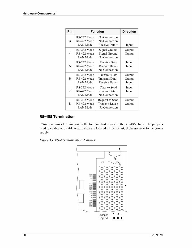
Hardware Components
80 025-9574E
RS-485 Termination
RS-485 requires termination on the first and last device in the RS-485 chain. The jumpers used to enable or disable termination are located inside the ACU chassis next to the power supply.
Figure 15: RS-485 Termination Jumpers
3RS-232 ModeRS-422 ModeLAN Mode
No ConnectionNo ConnectionReceive Data + Input
4RS-232 ModeRS-422 ModeLAN Mode
Signal GroundSignal GroundNo Connection
OutputOutput
5RS-232 ModeRS-422 ModeLAN Mode
Receive DataReceive Data -No Connection
InputInput
6RS-232 ModeRS-422 ModeLAN Mode
Transmit DataTransmit Data -Receive Data -
OutputOutputInput
7RS-232 ModeRS-422 ModeLAN Mode
Clear to SendReceive Data +No Connection
InputInput
8RS-232 ModeRS-422 ModeLAN Mode
Request to SendTransmit Data +No Connection
OutputOutput
Pin Function Direction
X23X24X22X21
X27X28X26X25
X31X32X30X29
X35X36X34X33
3 2 1Jumper Legend
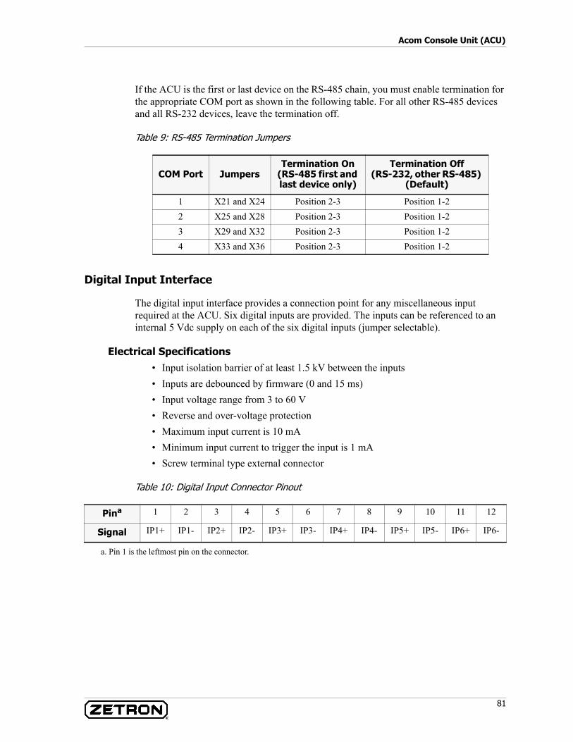
81
Acom Console Unit (ACU)
If the ACU is the first or last device on the RS-485 chain, you must enable termination for the appropriate COM port as shown in the following table. For all other RS-485 devices and all RS-232 devices, leave the termination off.
Table 9: RS-485 Termination Jumpers
Digital Input Interface
The digital input interface provides a connection point for any miscellaneous input required at the ACU. Six digital inputs are provided. The inputs can be referenced to an internal 5 Vdc supply on each of the six digital inputs (jumper selectable).
Electrical Specifications• Input isolation barrier of at least 1.5 kV between the inputs• Inputs are debounced by firmware (0 and 15 ms)• Input voltage range from 3 to 60 V• Reverse and over-voltage protection• Maximum input current is 10 mA• Minimum input current to trigger the input is 1 mA• Screw terminal type external connector
Table 10: Digital Input Connector Pinout
COM Port JumpersTermination On
(RS-485 first and last device only)
Termination Off(RS-232, other RS-485)
(Default)
1 X21 and X24 Position 2-3 Position 1-22 X25 and X28 Position 2-3 Position 1-23 X29 and X32 Position 2-3 Position 1-24 X33 and X36 Position 2-3 Position 1-2
Pina 1 2 3 4 5 6 7 8 9 10 11 12
Signal IP1+ IP1- IP2+ IP2- IP3+ IP3- IP4+ IP4- IP5+ IP5- IP6+ IP6-
a. Pin 1 is the leftmost pin on the connector.
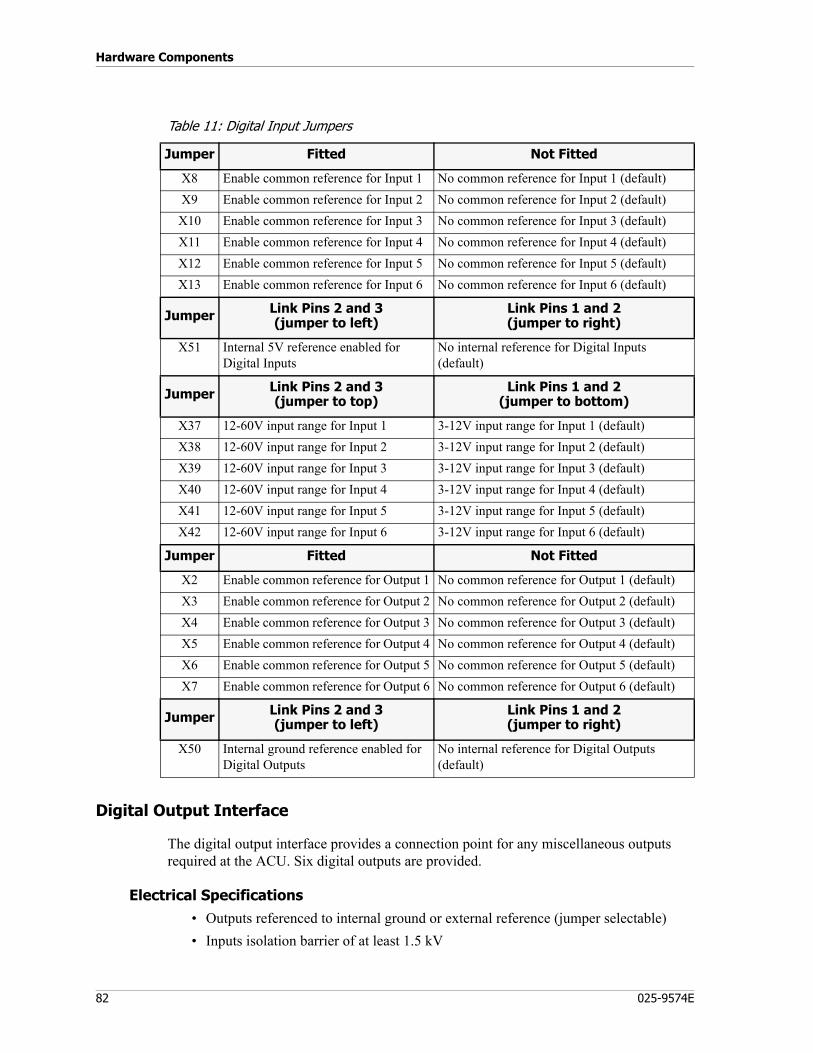
Hardware Components
82 025-9574E
Table 11: Digital Input Jumpers
Digital Output Interface
The digital output interface provides a connection point for any miscellaneous outputs required at the ACU. Six digital outputs are provided.
Electrical Specifications• Outputs referenced to internal ground or external reference (jumper selectable)• Inputs isolation barrier of at least 1.5 kV
Jumper Fitted Not Fitted
X8 Enable common reference for Input 1 No common reference for Input 1 (default)X9 Enable common reference for Input 2 No common reference for Input 2 (default)X10 Enable common reference for Input 3 No common reference for Input 3 (default)X11 Enable common reference for Input 4 No common reference for Input 4 (default)X12 Enable common reference for Input 5 No common reference for Input 5 (default)X13 Enable common reference for Input 6 No common reference for Input 6 (default)
Jumper Link Pins 2 and 3(jumper to left)
Link Pins 1 and 2(jumper to right)
X51 Internal 5V reference enabled for Digital Inputs
No internal reference for Digital Inputs (default)
Jumper Link Pins 2 and 3(jumper to top)
Link Pins 1 and 2(jumper to bottom)
X37 12-60V input range for Input 1 3-12V input range for Input 1 (default)X38 12-60V input range for Input 2 3-12V input range for Input 2 (default)X39 12-60V input range for Input 3 3-12V input range for Input 3 (default)X40 12-60V input range for Input 4 3-12V input range for Input 4 (default)X41 12-60V input range for Input 5 3-12V input range for Input 5 (default)X42 12-60V input range for Input 6 3-12V input range for Input 6 (default)
Jumper Fitted Not Fitted
X2 Enable common reference for Output 1 No common reference for Output 1 (default)X3 Enable common reference for Output 2 No common reference for Output 2 (default)X4 Enable common reference for Output 3 No common reference for Output 3 (default)X5 Enable common reference for Output 4 No common reference for Output 4 (default)X6 Enable common reference for Output 5 No common reference for Output 5 (default)X7 Enable common reference for Output 6 No common reference for Output 6 (default)
Jumper Link Pins 2 and 3(jumper to left)
Link Pins 1 and 2(jumper to right)
X50 Internal ground reference enabled for Digital Outputs
No internal reference for Digital Outputs (default)
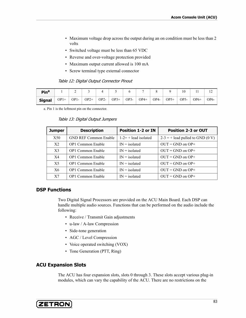
83
Acom Console Unit (ACU)
• Maximum voltage drop across the output during an on condition must be less than 2 volts
• Switched voltage must be less than 65 VDC• Reverse and over-voltage protection provided• Maximum output current allowed is 100 mA• Screw terminal type external connector
Table 12: Digital Output Connector Pinout
Table 13: Digital Output Jumpers
DSP Functions
Two Digital Signal Processors are provided on the ACU Main Board. Each DSP can handle multiple audio sources. Functions that can be performed on the audio include the following:
• Receive / Transmit Gain adjustments• u-law / A-law Compression• Side-tone generation• AGC / Level Compression• Voice operated switching (VOX)• Tone Generation (PTT, Ring)
ACU Expansion Slots
The ACU has four expansion slots, slots 0 through 3. These slots accept various plug-in modules, which can vary the capability of the ACU. There are no restrictions on the
Pina 1 2 3 4 5 6 7 8 9 10 11 12
Signal OP1+ OP1- OP2+ OP2- OP3+ OP3- OP4+ OP4- OP5+ OP5- OP6+ OP6-
a. Pin 1 is the leftmost pin on the connector.
Jumper Description Position 1-2 or IN Position 2-3 or OUT
X50 GND REF Common Enable 1-2= + lead isolated 2-3 = + lead pulled to GND (0 V)X2 OP1 Common Enable IN = isolated OUT = GND on OP+X3 OP1 Common Enable IN = isolated OUT = GND on OP+X4 OP1 Common Enable IN = isolated OUT = GND on OP+X5 OP1 Common Enable IN = isolated OUT = GND on OP+X6 OP1 Common Enable IN = isolated OUT = GND on OP+X7 OP1 Common Enable IN = isolated OUT = GND on OP+
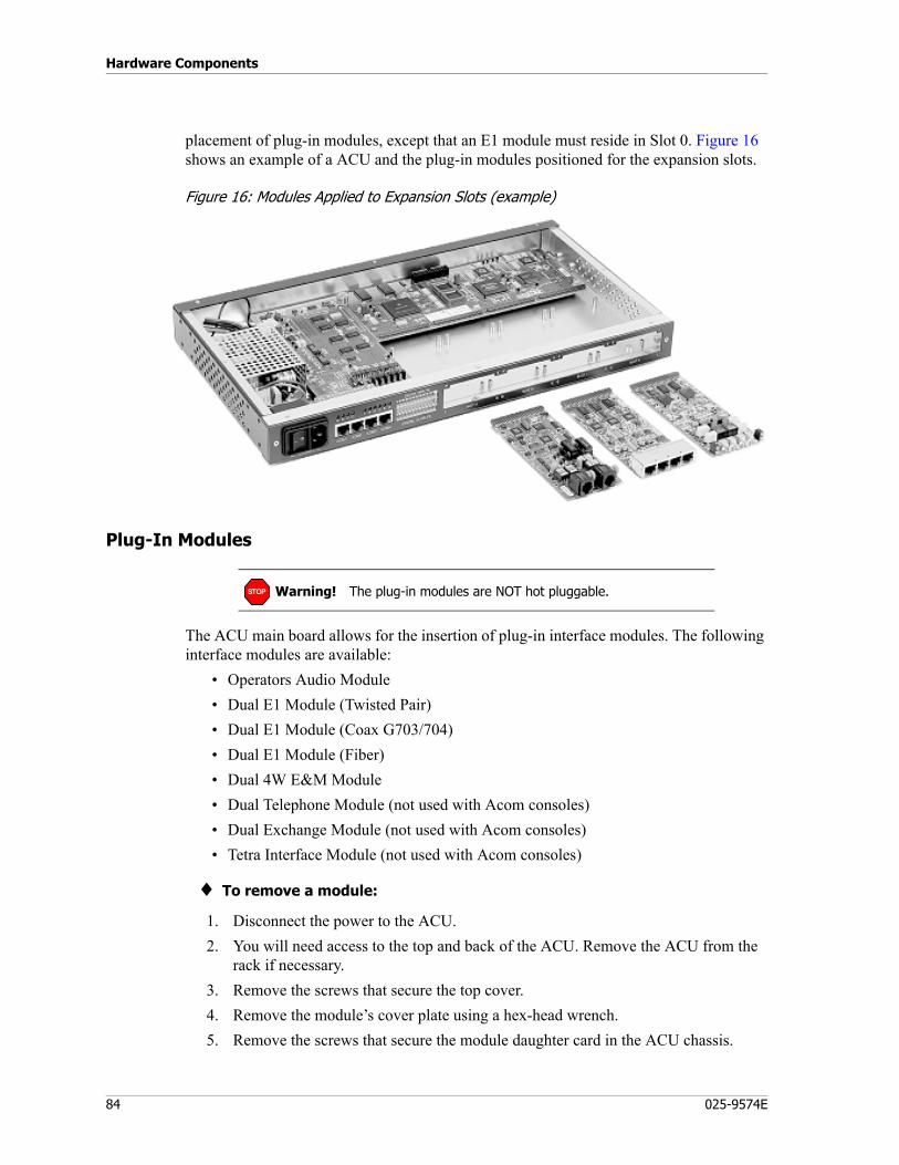
Hardware Components
84 025-9574E
placement of plug-in modules, except that an E1 module must reside in Slot 0. Figure 16 shows an example of a ACU and the plug-in modules positioned for the expansion slots.
Figure 16: Modules Applied to Expansion Slots (example)
Plug-In Modules
The ACU main board allows for the insertion of plug-in interface modules. The following interface modules are available:
• Operators Audio Module• Dual E1 Module (Twisted Pair)• Dual E1 Module (Coax G703/704)• Dual E1 Module (Fiber)• Dual 4W E&M Module• Dual Telephone Module (not used with Acom consoles)• Dual Exchange Module (not used with Acom consoles)• Tetra Interface Module (not used with Acom consoles)
♦ To remove a module:
1. Disconnect the power to the ACU.2. You will need access to the top and back of the ACU. Remove the ACU from the
rack if necessary.3. Remove the screws that secure the top cover.4. Remove the module’s cover plate using a hex-head wrench.5. Remove the screws that secure the module daughter card in the ACU chassis.
Warning! The plug-in modules are NOT hot pluggable.STOP
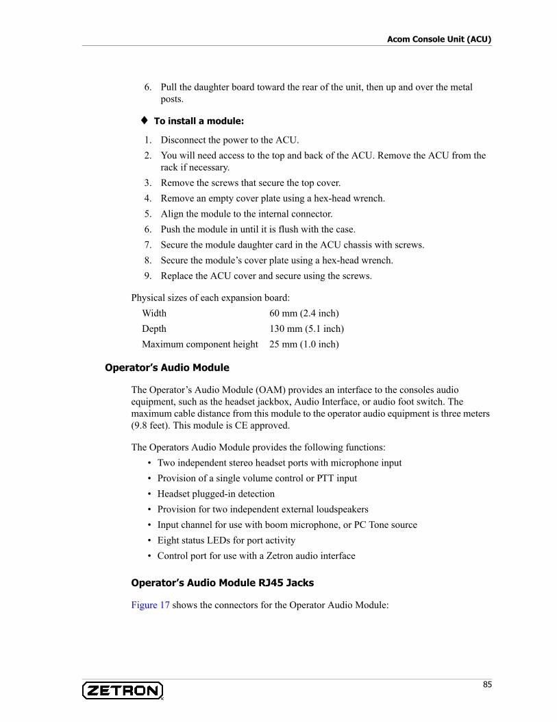
85
Acom Console Unit (ACU)
6. Pull the daughter board toward the rear of the unit, then up and over the metal posts.
♦ To install a module:
1. Disconnect the power to the ACU.2. You will need access to the top and back of the ACU. Remove the ACU from the
rack if necessary.3. Remove the screws that secure the top cover.4. Remove an empty cover plate using a hex-head wrench.5. Align the module to the internal connector.6. Push the module in until it is flush with the case.7. Secure the module daughter card in the ACU chassis with screws.8. Secure the module’s cover plate using a hex-head wrench.9. Replace the ACU cover and secure using the screws.
Physical sizes of each expansion board:Width 60 mm (2.4 inch)Depth 130 mm (5.1 inch)Maximum component height 25 mm (1.0 inch)
Operator’s Audio Module
The Operator’s Audio Module (OAM) provides an interface to the consoles audio equipment, such as the headset jackbox, Audio Interface, or audio foot switch. The maximum cable distance from this module to the operator audio equipment is three meters (9.8 feet). This module is CE approved.
The Operators Audio Module provides the following functions:• Two independent stereo headset ports with microphone input• Provision of a single volume control or PTT input• Headset plugged-in detection• Provision for two independent external loudspeakers• Input channel for use with boom microphone, or PC Tone source• Eight status LEDs for port activity• Control port for use with a Zetron audio interface
Operator’s Audio Module RJ45 Jacks
Figure 17 shows the connectors for the Operator Audio Module:
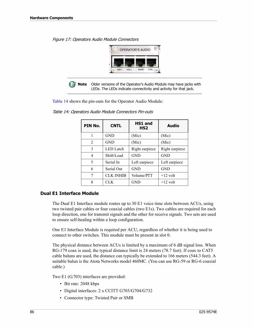
Hardware Components
86 025-9574E
Figure 17: Operators Audio Module Connectors
Table 14 shows the pin-outs for the Operator Audio Module:
Table 14: Operators Audio Module Connectors Pin-outs
Dual E1 Interface Module
The Dual E1 Interface module routes up to 30 E1 voice time slots between ACUs, using two twisted pair cables or four coaxial cables (two E1s). Two cables are required for each loop direction, one for transmit signals and the other for receive signals. Two sets are used to ensure self-healing within a loop configuration.
One E1 Interface Module is required per ACU, regardless of whether it is being used to connect to other switches. This module must be present in slot 0.
The physical distance between ACUs is limited by a maximum of 6 dB signal loss. When RG-179 coax is used, the typical distance limit is 24 meters (78.7 feet). If coax to CAT5 cable baluns are used, the distance can typically be extended to 166 meters (544.3 feet). A suitable balun is the Atota Networks model 460MC. (You can use RG-59 or RG-6 coaxial cable.)
Two E1 (G.703) interfaces are provided:• Bit rate: 2048 kbps• Digital interfaces: 2 x CCITT G703/G704/G732• Connector type: Twisted Pair or SMB
Note Older versions of the Operator’s Audio Module may have jacks with LEDs. The LEDs indicate connectivity and activity for that jack.
PIN No. CNTL HS1 and HS2 Audio
1 GND (Mic) (Mic)2 GND (Mic) (Mic)3 LED Latch Right earpiece Right earpiece4 Shift/Load GND GND5 Serial In Left earpiece Left earpiece6 Serial Out GND GND7 CLK INHIB Volume/PTT +12 volt8 CLK GND +12 volt
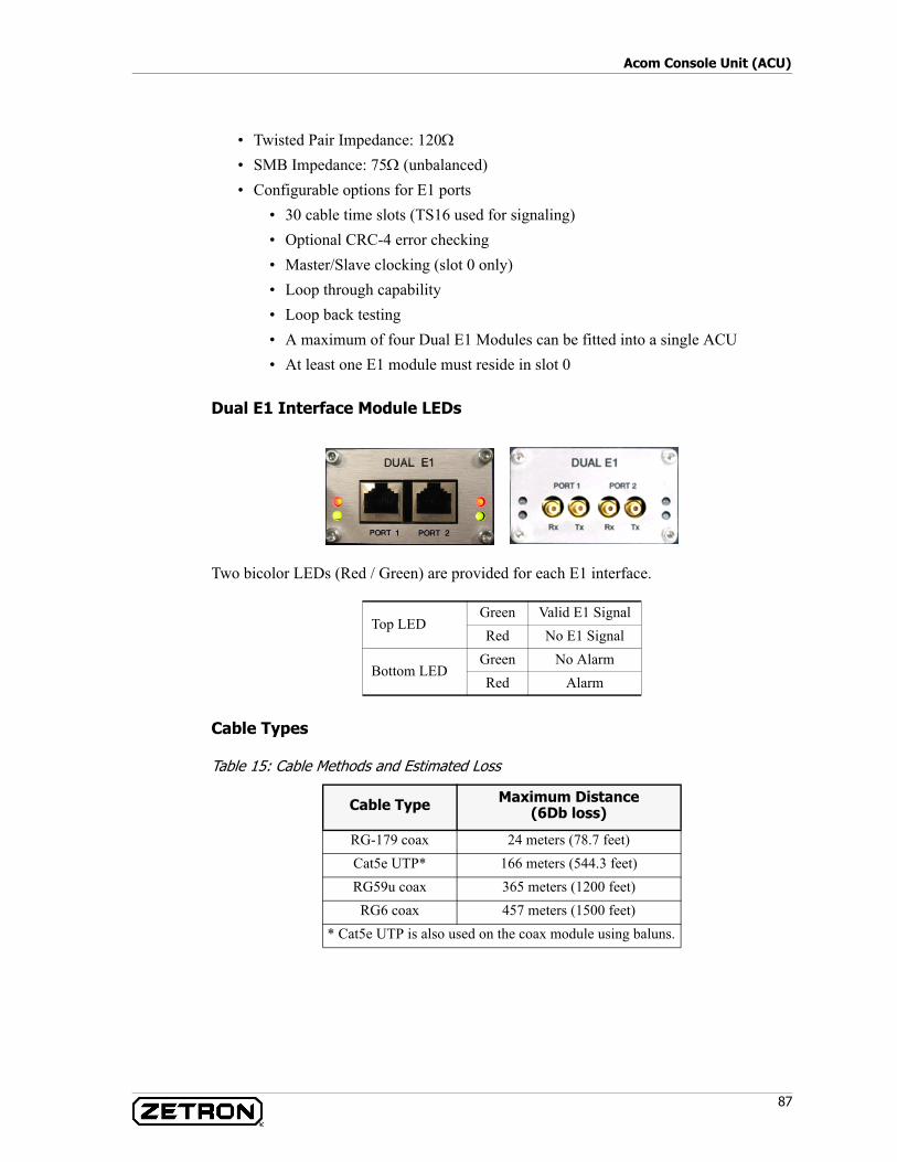
87
Acom Console Unit (ACU)
• Twisted Pair Impedance: 120Ω
• SMB Impedance: 75Ω (unbalanced)• Configurable options for E1 ports
• 30 cable time slots (TS16 used for signaling)• Optional CRC-4 error checking• Master/Slave clocking (slot 0 only)• Loop through capability• Loop back testing• A maximum of four Dual E1 Modules can be fitted into a single ACU• At least one E1 module must reside in slot 0
Dual E1 Interface Module LEDs
Two bicolor LEDs (Red / Green) are provided for each E1 interface.
Cable Types
Table 15: Cable Methods and Estimated Loss
Top LEDGreen Valid E1 SignalRed No E1 Signal
Bottom LEDGreen No AlarmRed Alarm
Cable Type Maximum Distance(6Db loss)
RG-179 coax 24 meters (78.7 feet)Cat5e UTP* 166 meters (544.3 feet)RG59u coax 365 meters (1200 feet)RG6 coax 457 meters (1500 feet)
* Cat5e UTP is also used on the coax module using baluns.

Hardware Components
88 025-9574E
Pinout (UTP Version)
The pinout for the UTP version is identical to the MCU E1 ports.
Dual E1 Fiber Module
The Dual E1 Fiber Module is a trunk line interface card that is primarily used to connect all of the ACUs in an Acom system together. When it is used to connect the ACUs, it can be installed only in Slot 0 of the ACU.
This module provides two E1 (G703) ports. The configurable options for the E1 ports include:
• 30 or 31 allocatable time slots (CAS in TS16)• Optional CRC-4 error checking • Master/Slave clocking (slot 0 only)• Loop back testing Specification
The Dual E1 Module can be used as the interface for a logging recorder for the Acom system. When used in this way, it can be installed in any of slots 1 through 4 of the ACU.
Specifications
Function Pins for Balanced Receive Pair
Pins for Balanced Transmit pair
Port 1 1, 2 4, 5Port 2 1, 2 4, 5
Parameter Single Mode Multi Mode
Data Rate 2048 kbps +/- 50 ppm 2048 kbps +/- 50 ppmDigital Interfaces CCIT G703/G704 CCIT G703/G704
Frame Format Double Frame or CRC Multiframe
Double Frame or CRC Multiframe
Physical Connector MT-RJ MT-RJLine Code NRZ NRZOptical Source 1300 nm laser 1300 nm LEDFiber Diameter 9 μm 62.5 μm / 125 μmTransmit Power -14 to -20 dBm -14 to -19 dBmTransmit Center Wavelength 1261 to 1360 nm 1270 to 1380 nmReceive Sensitivity -31 dBm -31 dBmReceiver Saturation -8 dBm -14 dBmAverage Transmission Distance 15 Km 2 KmOperating Temperature 0 to 50 degrees C 0 to 50 degrees CStorage Temperature -10 to 70 degrees C -10 to 70 degrees C
89
Acom Console Unit (ACU)
LEDs
There are two LEDs adjacent to each E1 port on the module. They indicate the status of the ports.
Table 16: Dual E1 Fiber Module LED Functions
Dual 4W E&M Module
The Dual 4W E&M module provides an interface to two analog, 4-wire, 600 ohm, E&M circuits, connecting fixed channel radios or 4-wire E&M telephone circuits, loggers or other 600 ohm circuits. Each circuit contains two sets of E&M signals. One set of E&M signals can be used for radio COR/PTT, using appropriate external interface circuitry. The function of the other set is programmable. Provisions exist for using either an internal 12 V, non-isolated reference voltage, or external, isolated reference voltages for the E&M leads of the ACU. The physical connection for each circuit is an 8-conductor, 8-position RJ-45 connector. This module may be present in slots one through three. This module is CE approved.
Each channel provides the following:• A balanced 2-wire 600 ohm transformer isolated audio Input.• A balanced 2-wire 600 ohm transformer isolated audio Output.• Two opto-isolated inputs (E leads).• Two opto-isolated outputs (M leads).• Two voltage reference leads are provided for the E and M leads.• An LED indication for each E&M lead.
Humidity 45% RH at 45 degrees C 45% RH at 45 degrees CMaximum Power Consumption +5V 300mA 300mAMaximum Power Consumption +12V 0mA 0mA
LED Position Description Color Function
Top LED left of Port 1 Port 1 Signal StatusRed Loss of Signal
Green Valid Signal
Bottom LED left of Port 1 Port 1 Alarm StatusRed RRA Alarm active
Green RRA Alarm inactive
Top LED right of Port 2 Port 2 Signal StatusRed Loss of Signal
Green Valid Signal
Bottom LED right of Port 2 Port 2 Alarm StatusRed RRA Alarm active
Green RRA Alarm inactive
Parameter Single Mode Multi Mode
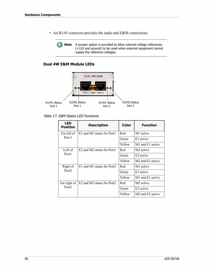
Hardware Components
90 025-9574E
• An RJ-45 connector provides the audio and E&M connections.
Dual 4W E&M Module LEDs
Table 17: E&M Status LED Functions
Note A jumper option is provided to allow internal voltage references (+12V and ground) to be used when external equipment cannot supply the reference voltages.
LEDPosition Description Color Function
Far left of Port 1
E1 and M1 status for Port1 Red M1 activeGreen E1 activeYellow M1 and E1 active
Left of Port1
E2 and M2 status for Port1 Red M2 activeGreen E2 activeYellow M2 and E2 active
Right of Port2
E1 and M1 status for Port2 Red M1 activeGreen E1 activeYellow M1 and E1 active
Far right of Port2
E2 and M2 status for Port2 Red M2 activeGreen E2 activeYellow M2 and E2 active
E1/M1 StatusPort 1
E2/M2 StatusPort 1
E1/M1 StatusPort 2
E2/M2 StatusPort 2
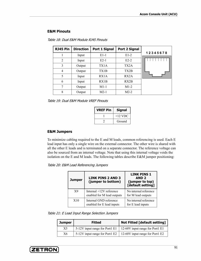
91
Acom Console Unit (ACU)
E&M Pinouts
Table 18: Dual E&M Module RJ45 Pinouts
Table 19: Dual E&M Module VREF Pinouts
E&M Jumpers
To minimize cabling required to the E and M leads, common referencing is used. Each E lead input has only a single wire on the external connector. The other wire is shared with all the other E leads and is terminated on a separate connector. The reference voltage can also be sourced from an internal voltage. Note that using this internal voltage voids the isolation on the E and M leads. The following tables describe E&M jumper positioning:
Table 20: E&M Lead Referencing Jumpers
Table 21: E Lead Input Range Selection Jumpers
RJ45 Pin Direction Port 1 Signal Port 2 Signal
1 Input E1-1 E1-22 Input E2-1 E2-23 Output TX1A TX2A4 Output TX1B TX2B5 Input RX1A RX2A6 Input RX1B RX2B7 Output M1-1 M1-28 Output M2-1 M2-2
VREF Pin Signal
1 +12 VDC2 Ground
Jumper LINK PINS 2 AND 3(jumper to bottom)
LINK PINS 1 AND 2
(jumper to top)[default setting]
X9 Internal +12V reference enabled for M lead outputs
No internal reference for M lead outputs
X10 Internal GND reference enabled for E lead inputs
No internal reference for E lead inputs
Jumper Fitted Not Fitted [default setting]
X5 5-12V input range for Port1 E1 12-60V input range for Port1 E1X6 5-12V input range for Port1 E2 12-60V input range for Port1 E2
1 2 3 4 5 6 7 8
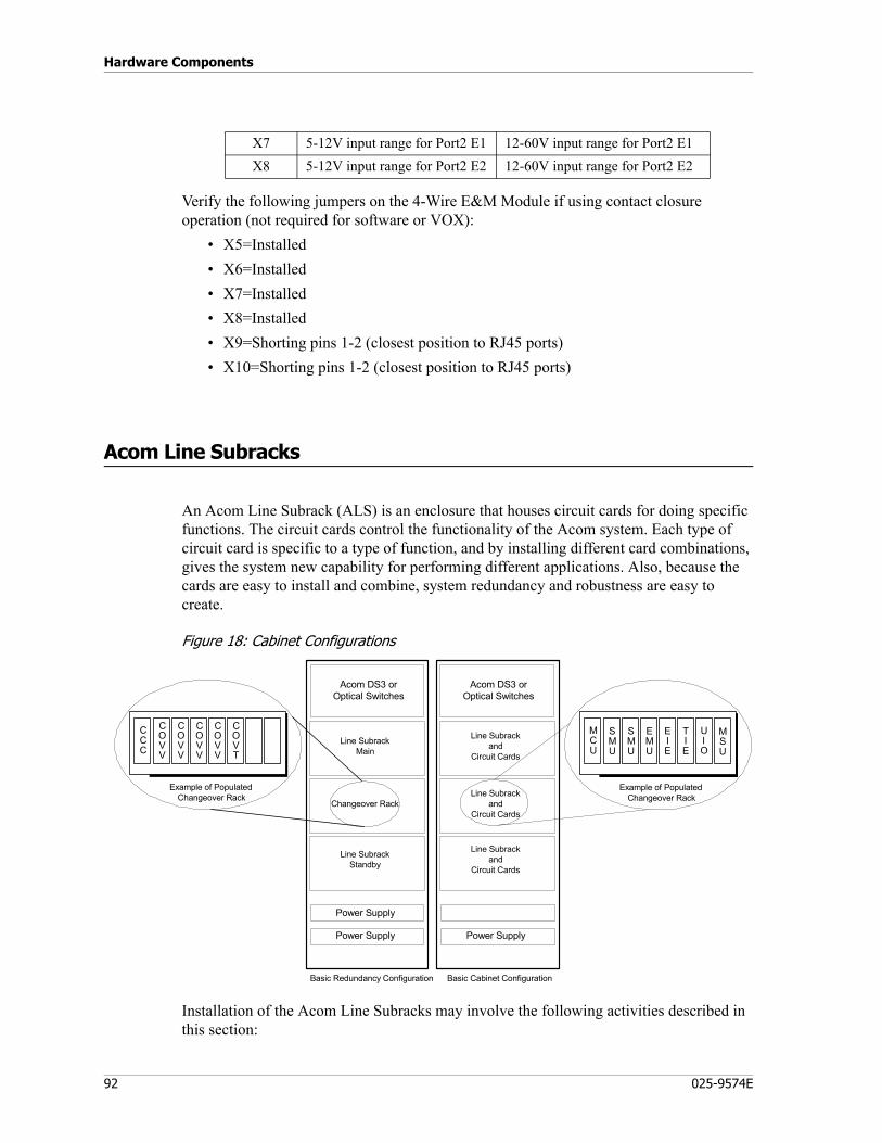
Hardware Components
92 025-9574E
Verify the following jumpers on the 4-Wire E&M Module if using contact closure operation (not required for software or VOX):
• X5=Installed• X6=Installed• X7=Installed• X8=Installed• X9=Shorting pins 1-2 (closest position to RJ45 ports)• X10=Shorting pins 1-2 (closest position to RJ45 ports)
Acom Line Subracks
An Acom Line Subrack (ALS) is an enclosure that houses circuit cards for doing specific functions. The circuit cards control the functionality of the Acom system. Each type of circuit card is specific to a type of function, and by installing different card combinations, gives the system new capability for performing different applications. Also, because the cards are easy to install and combine, system redundancy and robustness are easy to create.
Figure 18: Cabinet Configurations
Installation of the Acom Line Subracks may involve the following activities described in this section:
X7 5-12V input range for Port2 E1 12-60V input range for Port2 E1X8 5-12V input range for Port2 E2 12-60V input range for Port2 E2
Line Subrackand
Circuit Cards
Line Subrackand
Circuit Cards
Line Subrackand
Circuit Cards
Power Supply
Basic Cabinet ConfigurationBasic Redundancy Configuration
Line SubrackMain
Changeover Rack
Line SubrackStandby
Acom DS3 orOptical Switches
Power Supply
Power Supply
SMU
MCU
SMU
EMU
MSU
Example of PopulatedChangeover Rack
TIE
EIE
UIO
CCC
Example of PopulatedChangeover Rack
COVV
COVV
COVV
COVV
COVT
Acom DS3 orOptical Switches
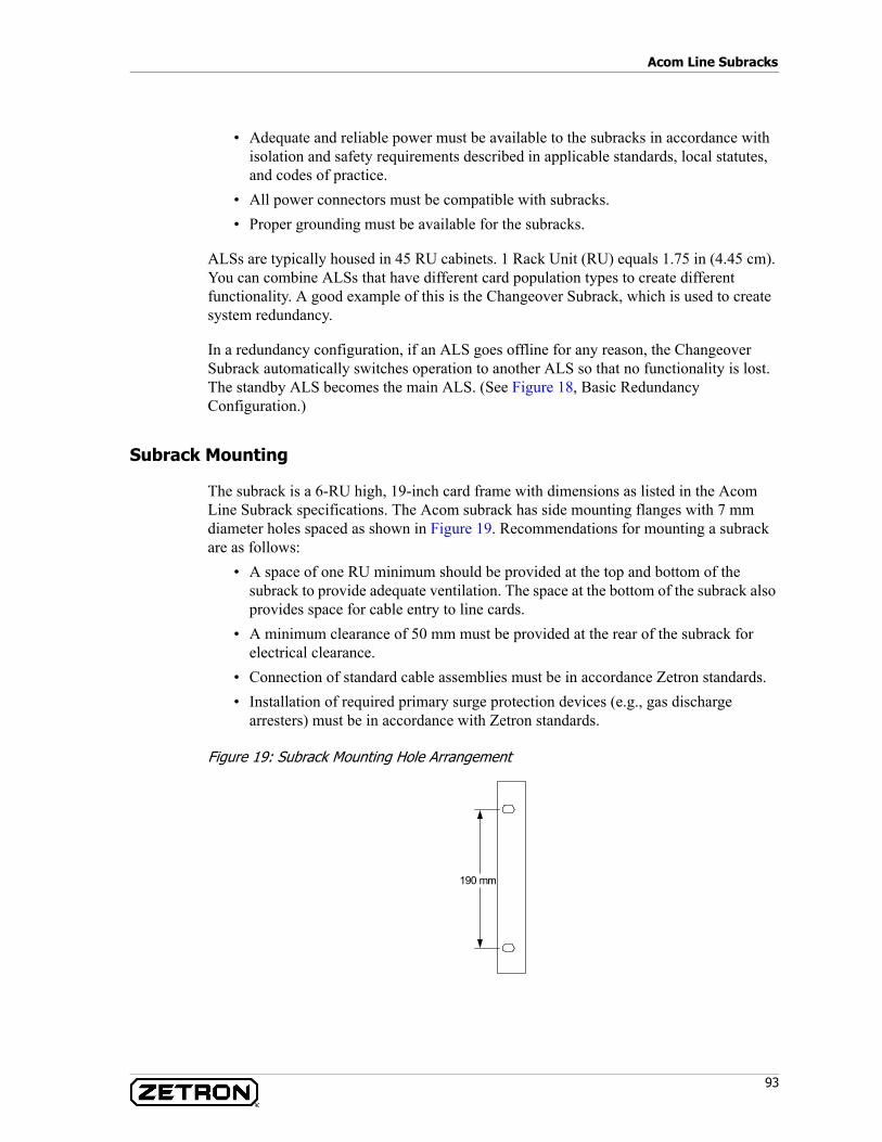
93
Acom Line Subracks
• Adequate and reliable power must be available to the subracks in accordance with isolation and safety requirements described in applicable standards, local statutes, and codes of practice.
• All power connectors must be compatible with subracks.• Proper grounding must be available for the subracks.
ALSs are typically housed in 45 RU cabinets. 1 Rack Unit (RU) equals 1.75 in (4.45 cm). You can combine ALSs that have different card population types to create different functionality. A good example of this is the Changeover Subrack, which is used to create system redundancy.
In a redundancy configuration, if an ALS goes offline for any reason, the Changeover Subrack automatically switches operation to another ALS so that no functionality is lost. The standby ALS becomes the main ALS. (See Figure 18, Basic Redundancy Configuration.)
Subrack Mounting
The subrack is a 6-RU high, 19-inch card frame with dimensions as listed in the Acom Line Subrack specifications. The Acom subrack has side mounting flanges with 7 mm diameter holes spaced as shown in Figure 19. Recommendations for mounting a subrack are as follows:
• A space of one RU minimum should be provided at the top and bottom of the subrack to provide adequate ventilation. The space at the bottom of the subrack also provides space for cable entry to line cards.
• A minimum clearance of 50 mm must be provided at the rear of the subrack for electrical clearance.
• Connection of standard cable assemblies must be in accordance Zetron standards.• Installation of required primary surge protection devices (e.g., gas discharge
arresters) must be in accordance with Zetron standards.
Figure 19: Subrack Mounting Hole Arrangement
190 mm
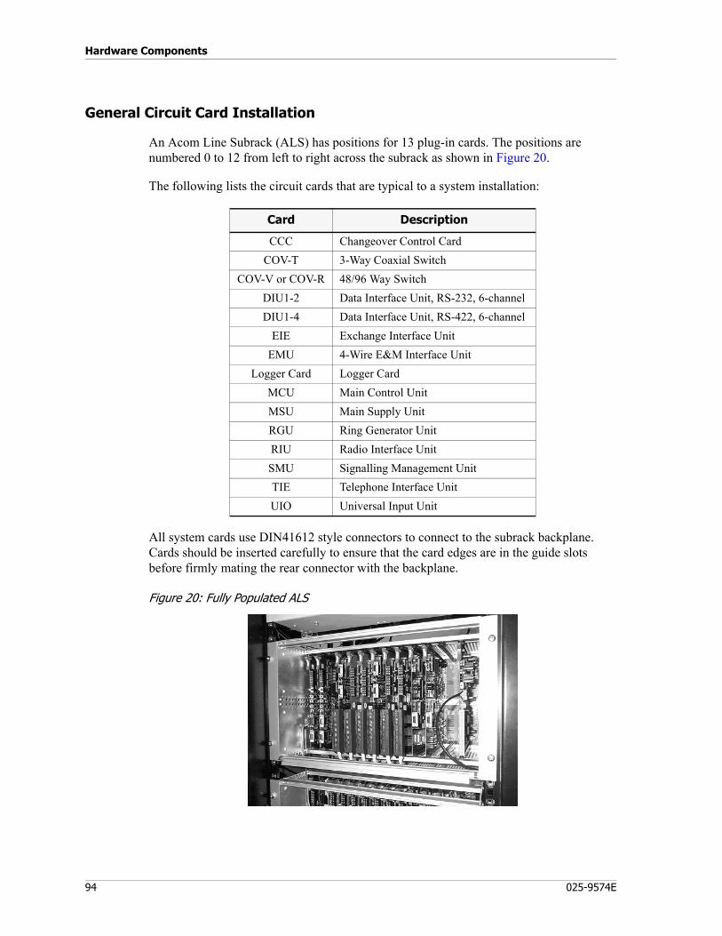
Hardware Components
94 025-9574E
General Circuit Card Installation
An Acom Line Subrack (ALS) has positions for 13 plug-in cards. The positions are numbered 0 to 12 from left to right across the subrack as shown in Figure 20.
The following lists the circuit cards that are typical to a system installation:
All system cards use DIN41612 style connectors to connect to the subrack backplane. Cards should be inserted carefully to ensure that the card edges are in the guide slots before firmly mating the rear connector with the backplane.
Figure 20: Fully Populated ALS
Card Description
CCC Changeover Control CardCOV-T 3-Way Coaxial Switch
COV-V or COV-R 48/96 Way SwitchDIU1-2 Data Interface Unit, RS-232, 6-channel DIU1-4 Data Interface Unit, RS-422, 6-channel
EIE Exchange Interface UnitEMU 4-Wire E&M Interface Unit
Logger Card Logger CardMCU Main Control UnitMSU Main Supply UnitRGU Ring Generator UnitRIU Radio Interface UnitSMU Signalling Management UnitTIE Telephone Interface UnitUIO Universal Input Unit
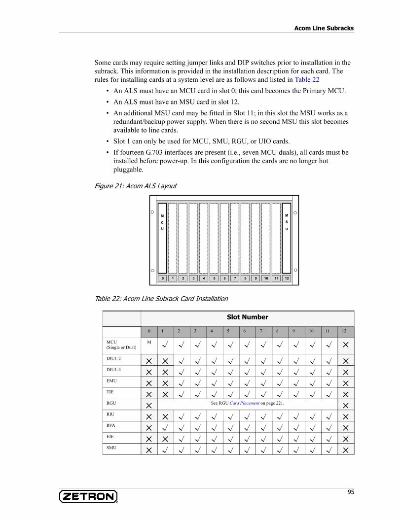
95
Acom Line Subracks
Some cards may require setting jumper links and DIP switches prior to installation in the subrack. This information is provided in the installation description for each card. The rules for installing cards at a system level are as follows and listed in Table 22
• An ALS must have an MCU card in slot 0; this card becomes the Primary MCU.• An ALS must have an MSU card in slot 12.• An additional MSU card may be fitted in Slot 11; in this slot the MSU works as a
redundant/backup power supply. When there is no second MSU this slot becomes available to line cards.
• Slot 1 can only be used for MCU, SMU, RGU, or UIO cards.• If fourteen G.703 interfaces are present (i.e., seven MCU duals), all cards must be
installed before power-up. In this configuration the cards are no longer hot pluggable.
Figure 21: Acom ALS Layout
Table 22: Acom Line Subrack Card Installation
Slot Number
0 1 2 3 4 5 6 7 8 9 10 11 12
MCU(Single or Dual)
M
DIU1-2
DIU1-4
EMU
TIE
RGU See RGU Card Placement on page 221.
RIU
RVA
EIE
SMU
2 3 4 5 6 7 8 9
M
U
S
1210 1110
M
UC
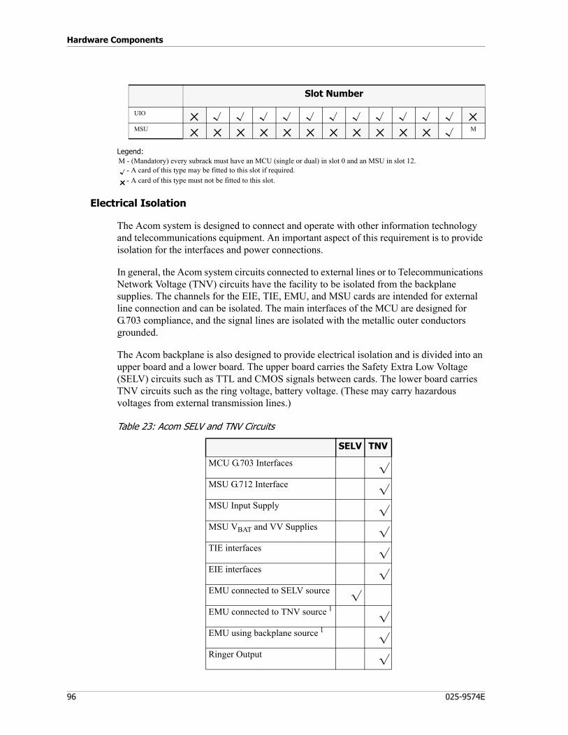
Hardware Components
96 025-9574E
Legend:M - (Mandatory) every subrack must have an MCU (single or dual) in slot 0 and an MSU in slot 12.
- A card of this type may be fitted to this slot if required.- A card of this type must not be fitted to this slot.
Electrical Isolation
The Acom system is designed to connect and operate with other information technology and telecommunications equipment. An important aspect of this requirement is to provide isolation for the interfaces and power connections.
In general, the Acom system circuits connected to external lines or to Telecommunications Network Voltage (TNV) circuits have the facility to be isolated from the backplane supplies. The channels for the EIE, TIE, EMU, and MSU cards are intended for external line connection and can be isolated. The main interfaces of the MCU are designed for G.703 compliance, and the signal lines are isolated with the metallic outer conductors grounded.
The Acom backplane is also designed to provide electrical isolation and is divided into an upper board and a lower board. The upper board carries the Safety Extra Low Voltage (SELV) circuits such as TTL and CMOS signals between cards. The lower board carries TNV circuits such as the ring voltage, battery voltage. (These may carry hazardous voltages from external transmission lines.)
Table 23: Acom SELV and TNV Circuits
UIO
MSU M
Slot Number
SELV TNV
MCU G.703 Interfaces
MSU G.712 Interface
MSU Input Supply
MSU VBAT and VV Supplies
TIE interfaces
EIE interfaces
EMU connected to SELV source
EMU connected to TNV source 1
EMU using backplane source 1
Ringer Output
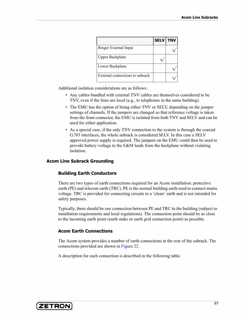
97
Acom Line Subracks
Additional isolation considerations are as follows:• Any cables bundled with external TNV cables are themselves considered to be
TNV, even if the lines are local (e.g., to telephones in the same building).• The EMU has the option of being either TNV or SELV, depending on the jumper
settings of channels. If the jumpers are changed so that reference voltage is taken from the front connector, the EMU is isolated from both TNV and SELV and can be used for either application.
• As a special case, if the only TNV connection to the system is through the coaxial G.703 interfaces, the whole subrack is considered SELV. In this case a SELV approved power supply is required. The jumpers on the EMU could then be used to provide battery voltage to the E&M leads from the backplane without violating isolation.
Acom Line Subrack Grounding
Building Earth Conductors
There are two types of earth connections required for an Acom installation: protective earth (PE) and telecom earth (TRC). PE is the normal building earth used to connect mains voltage. TRC is provided for connecting circuits to a ‘clean’ earth and is not intended for safety purposes.
Typically, there should be one connection between PE and TRC in the building (subject to installation requirements and local regulations). The connection point should be as close to the incoming earth point (earth stake or earth grid connection point) as possible.
Acom Earth Connections
The Acom system provides a number of earth connections at the rear of the subrack. The connections provided are shown in Figure 22.
A description for each connection is described in the following table.
Ringer External Input
Upper Backplane
Lower Backplane
External connections to subrack
SELV TNV

Hardware Components
98 025-9574E
Table 24: Acom Earth Connection
Figure 22: Acom Subrack Earth Connections
Connection Description PE TRC SELV TNV
J15: 1 and 2 Subrack chassis connection
J14: 2 and 3 SELV system earth
J18: 1 to 4 SELV electrostatic discharge protection
J20: 1 +VBAT (DC power positive supply)
J17: 2 to 4 TNV electrostatic discharge protection
J13-BATGNDGNDRING
J14
Upper BackplaneJ15
J13
PROTECTIVEEARTH
(PE)
J18
Lower Backplane
J20
J17TNVESDGNDTELECOM
EARTH(TRC)

99
Acom Line Subracks
Signal Cable Connections
Standard Cable Assemblies
The recommended method of signal cable connection is to use standard cable assemblies, which are available in a range of lengths. The assemblies are fitted with ferrite cores when required for compliance to EMC standards. Available types are listed in the Table 25.
Table 25: Acom Cable Assemblies
Tip If the cable assembly description includes a length, that length denotes the standard length of the cable.
The -xxx part of the cable number is optional. If it is present on the cable, the number denotes the length of the finished cable. An additional -M or -F indicates meters or feet.
For example, cable “709-7699-10-F D” indicates a 10 foot long cable, revision D (fourth revision of the cable with this number).
Part Numbers Cable Assembly
408-0045-xxx RJ-21, 25-Pair Plenum cable, 80 feet (24.4m)
709-0059-xxx PC-PC Null Modem Cable
709-0060-xxx Intercabinet Patch Panel
709-0062-xxx Multi-mode fiber, 7 meters (23 feet)
709-0063-xxx Multi-mode fiber, 12 inches (30.5cm)
709-0065-xxx Cat5e, black, 6 feet (1.8m)
709-7345-xxx Straight-through RS-232 9-pin M/F test cable
709-7592-xxx SMU Diagnostic cable
709-7601-xxx COV 12 pair to tail
709-7602-xxx COV 25 pair to tail
709-7604-xxx EIE to COV
709-7605-xxx UIO to COV upper cable, 1 foot (30.5cm)
709-7606-xxx MCU(T1) to COV
709-7611-xxx BNC to SMB
709-7612-xxx SMB to SMB
709-7613-xxx BNC to BNC
709-7615-xxx PC to Acom Console Unit (RS-232 Data)
709-7616-xxx Acom Console Unit to Modem
709-7617-xxx Acom Console Unit to generic speakers (audio cable)
709-7618-xxx Power Supply L5-15P cable
709-7630-xxx EMU to COV
709-7637-xxx Operator position wiring, AFT control cable
709-7638-xxx Operator position wiring, speaker cable
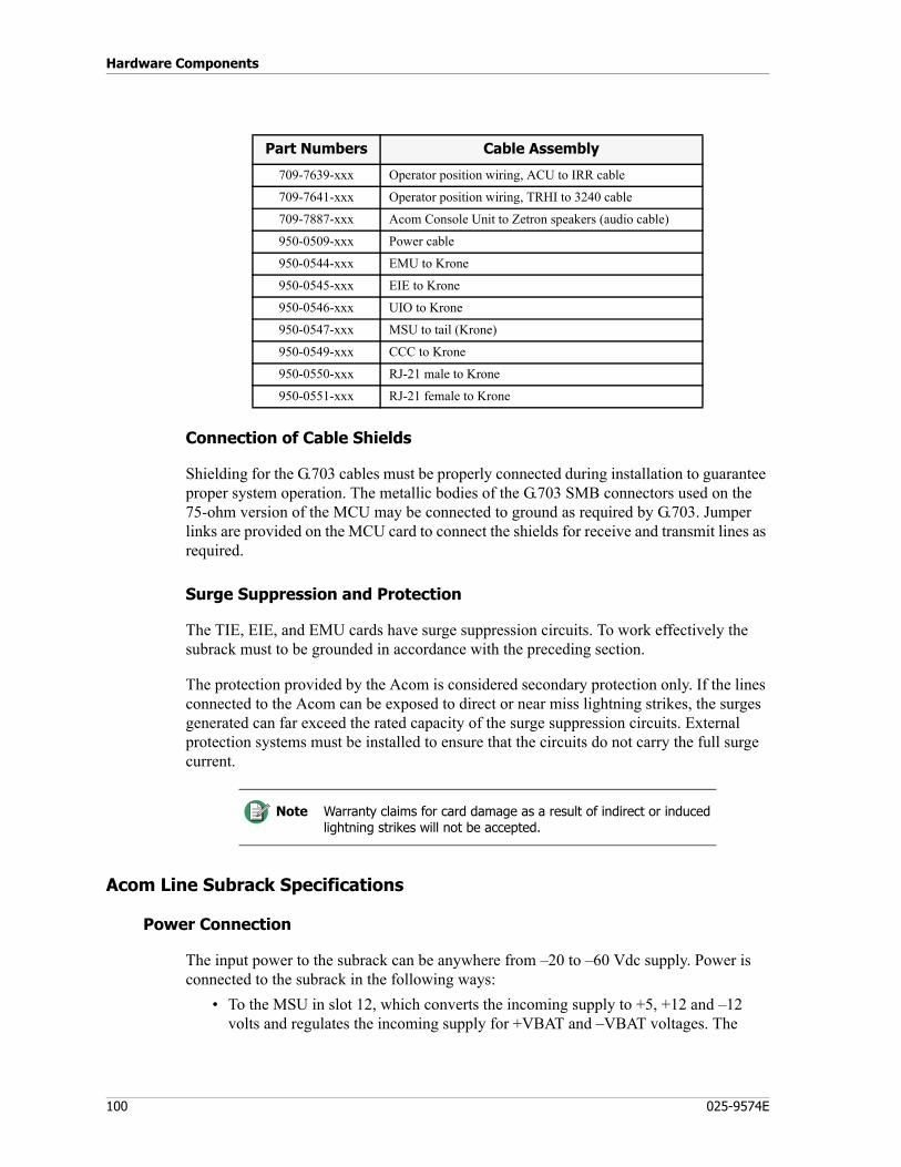
Hardware Components
100 025-9574E
Connection of Cable Shields
Shielding for the G.703 cables must be properly connected during installation to guarantee proper system operation. The metallic bodies of the G.703 SMB connectors used on the 75-ohm version of the MCU may be connected to ground as required by G.703. Jumper links are provided on the MCU card to connect the shields for receive and transmit lines as required.
Surge Suppression and Protection
The TIE, EIE, and EMU cards have surge suppression circuits. To work effectively the subrack must to be grounded in accordance with the preceding section.
The protection provided by the Acom is considered secondary protection only. If the lines connected to the Acom can be exposed to direct or near miss lightning strikes, the surges generated can far exceed the rated capacity of the surge suppression circuits. External protection systems must be installed to ensure that the circuits do not carry the full surge current.
Acom Line Subrack Specifications
Power Connection
The input power to the subrack can be anywhere from –20 to –60 Vdc supply. Power is connected to the subrack in the following ways:
• To the MSU in slot 12, which converts the incoming supply to +5, +12 and –12 volts and regulates the incoming supply for +VBAT and –VBAT voltages. The
709-7639-xxx Operator position wiring, ACU to IRR cable
709-7641-xxx Operator position wiring, TRHI to 3240 cable
709-7887-xxx Acom Console Unit to Zetron speakers (audio cable)
950-0509-xxx Power cable
950-0544-xxx EMU to Krone
950-0545-xxx EIE to Krone
950-0546-xxx UIO to Krone
950-0547-xxx MSU to tail (Krone)
950-0549-xxx CCC to Krone
950-0550-xxx RJ-21 male to Krone
950-0551-xxx RJ-21 female to Krone
Note Warranty claims for card damage as a result of indirect or induced lightning strikes will not be accepted.
Part Numbers Cable Assembly
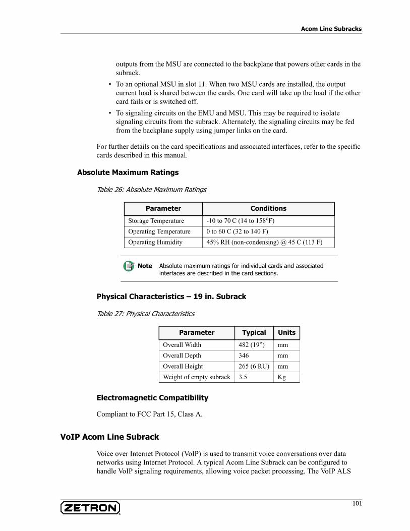
101
Acom Line Subracks
outputs from the MSU are connected to the backplane that powers other cards in the subrack.
• To an optional MSU in slot 11. When two MSU cards are installed, the output current load is shared between the cards. One card will take up the load if the other card fails or is switched off.
• To signaling circuits on the EMU and MSU. This may be required to isolate signaling circuits from the subrack. Alternately, the signaling circuits may be fed from the backplane supply using jumper links on the card.
For further details on the card specifications and associated interfaces, refer to the specific cards described in this manual.
Absolute Maximum Ratings
Table 26: Absolute Maximum Ratings
Physical Characteristics – 19 in. Subrack
Table 27: Physical Characteristics
Electromagnetic Compatibility
Compliant to FCC Part 15, Class A.
VoIP Acom Line Subrack
Voice over Internet Protocol (VoIP) is used to transmit voice conversations over data networks using Internet Protocol. A typical Acom Line Subrack can be configured to handle VoIP signaling requirements, allowing voice packet processing. The VoIP ALS
Parameter Conditions
Storage Temperature -10 to 70 C (14 to 158oF)Operating Temperature 0 to 60 C (32 to 140 F)Operating Humidity 45% RH (non-condensing) @ 45 C (113 F)
Note Absolute maximum ratings for individual cards and associated interfaces are described in the card sections.
Parameter Typical Units
Overall Width 482 (19”) mmOverall Depth 346 mmOverall Height 265 (6 RU) mmWeight of empty subrack 3.5 Kg
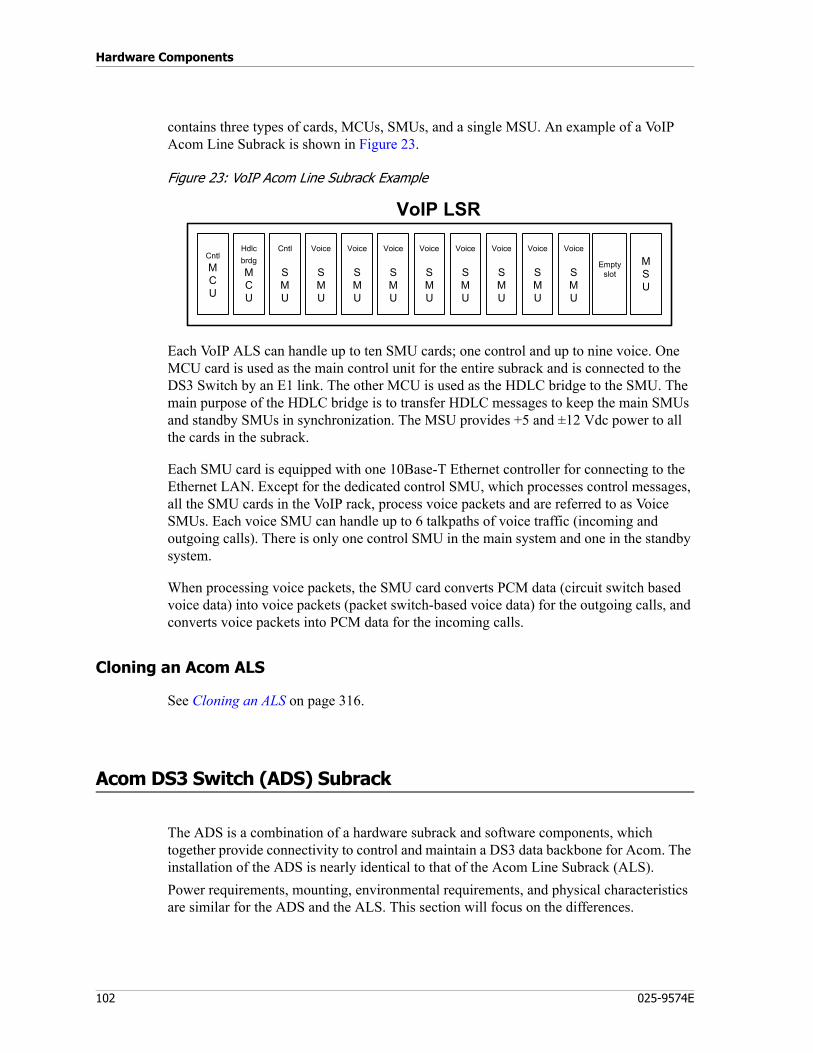
Hardware Components
102 025-9574E
contains three types of cards, MCUs, SMUs, and a single MSU. An example of a VoIP Acom Line Subrack is shown in Figure 23.
Figure 23: VoIP Acom Line Subrack Example
Each VoIP ALS can handle up to ten SMU cards; one control and up to nine voice. One MCU card is used as the main control unit for the entire subrack and is connected to the DS3 Switch by an E1 link. The other MCU is used as the HDLC bridge to the SMU. The main purpose of the HDLC bridge is to transfer HDLC messages to keep the main SMUs and standby SMUs in synchronization. The MSU provides +5 and ±12 Vdc power to all the cards in the subrack.
Each SMU card is equipped with one 10Base-T Ethernet controller for connecting to the Ethernet LAN. Except for the dedicated control SMU, which processes control messages, all the SMU cards in the VoIP rack, process voice packets and are referred to as Voice SMUs. Each voice SMU can handle up to 6 talkpaths of voice traffic (incoming and outgoing calls). There is only one control SMU in the main system and one in the standby system.
When processing voice packets, the SMU card converts PCM data (circuit switch based voice data) into voice packets (packet switch-based voice data) for the outgoing calls, and converts voice packets into PCM data for the incoming calls.
Cloning an Acom ALS
See Cloning an ALS on page 316.
Acom DS3 Switch (ADS) Subrack
The ADS is a combination of a hardware subrack and software components, which together provide connectivity to control and maintain a DS3 data backbone for Acom. The installation of the ADS is nearly identical to that of the Acom Line Subrack (ALS).Power requirements, mounting, environmental requirements, and physical characteristics are similar for the ADS and the ALS. This section will focus on the differences.
VoIP LSR
HdlcbrdgMCU
CntlMCU
Cntl
SMU
Voice
SMU
Voice
SMU
Voice
SMU
Voice
SMU
Voice
SMU
Voice
SMU
Voice
SMU
Voice
SMU
Emptyslot
MSU
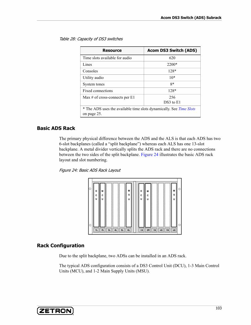
103
Acom DS3 Switch (ADS) Subrack
Table 28: Capacity of DS3 switches
Basic ADS Rack
The primary physical difference between the ADS and the ALS is that each ADS has two 6-slot backplanes (called a “split backplane”) whereas each ALS has one 13-slot backplane. A metal divider vertically splits the ADS rack and there are no connections between the two sides of the split backplane. Figure 24 illustrates the basic ADS rack layout and slot numbering.
Figure 24: Basic ADS Rack Layout
Rack Configuration
Due to the split backplane, two ADSs can be installed in an ADS rack.
The typical ADS configuration consists of a DS3 Control Unit (DCU), 1-3 Main Control Units (MCU), and 1-2 Main Supply Units (MSU).
Resource Acom DS3 Switch (ADS)
Time slots available for audio 620Lines 2200*Consoles 128*Utility audio 10*System tones 8*Fixed connections 128*Max # of cross-connects per E1 256
DS3 to E1* The ADS uses the available time slots dynamically. See Time Slots on page 25.
3L 4L 5L 6L 1R 2R 3R
M
U
S
6R4R 5R2L1L
D
UC
D
UC
M
U
SM
UC
M
UC
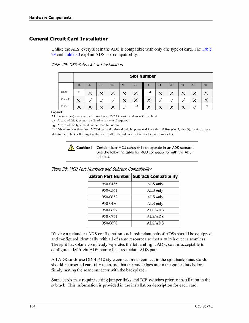
Hardware Components
104 025-9574E
General Circuit Card Installation
Unlike the ALS, every slot in the ADS is compatible with only one type of card. The Table 29 and Table 30 explain ADS slot compatibility:
Table 29: DS3 Subrack Card Installation
Legend:M - (Mandatory) every subrack must have a DCU in slot 0 and an MSU in slot 6.
- A card of this type may be fitted to this slot if required.- A card of this type must not be fitted to this slot.
* - If there are less than three MCU4 cards, the slots should be populated from the left first (slot 2, then 3), leaving empty slots to the right. (Left to right within each half of the subrack, not across the entire subrack.)
Table 30: MCU Part Numbers and Subrack Compatibility
If using a redundant ADS configuration, each redundant pair of ADSs should be equipped and configured identically with all of same resources so that a switch over is seamless. The split backplane completely separates the left and right ADS, so it is acceptable to configure a left/right ADS pair to be a redundant ADS pair.
All ADS cards use DIN41612 style connectors to connect to the split backplane. Cards should be inserted carefully to ensure that the card edges are in the guide slots before firmly mating the rear connector with the backplane.
Some cards may require setting jumper links and DIP switches prior to installation in the subrack. This information is provided in the installation description for each card.
Slot Number
1L 2L 3L 4L 5L 6L 1R 2R 3R 4R 5R 6R
DCU M M
MCU4*
MSU M M
Caution! Certain older MCU cards will not operate in an ADS subrack. See the following table for MCU compatibility with the ADS subrack.
!
Zetron Part Number Subrack Compatibility
950-0485 ALS only950-0561 ALS only950-0652 ALS only950-0486 ALS only950-0697 ALS/ADS950-0771 ALS/ADS950-0698 ALS/ADS
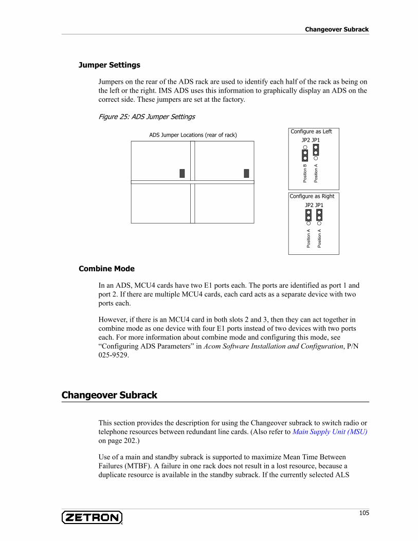
105
Changeover Subrack
Jumper Settings
Jumpers on the rear of the ADS rack are used to identify each half of the rack as being on the left or the right. IMS ADS uses this information to graphically display an ADS on the correct side. These jumpers are set at the factory.
Figure 25: ADS Jumper Settings
Combine Mode
In an ADS, MCU4 cards have two E1 ports each. The ports are identified as port 1 and port 2. If there are multiple MCU4 cards, each card acts as a separate device with two ports each.
However, if there is an MCU4 card in both slots 2 and 3, then they can act together in combine mode as one device with four E1 ports instead of two devices with two ports each. For more information about combine mode and configuring this mode, see “Configuring ADS Parameters” in Acom Software Installation and Configuration, P/N 025-9529.
Changeover Subrack
This section provides the description for using the Changeover subrack to switch radio or telephone resources between redundant line cards. (Also refer to Main Supply Unit (MSU) on page 202.)
Use of a main and standby subrack is supported to maximize Mean Time Between Failures (MTBF). A failure in one rack does not result in a lost resource, because a duplicate resource is available in the standby subrack. If the currently selected ALS
Configure as Left
JP2 JP1
Configure as Right
JP2 JP1
Pos
ition
A
Pos
ition
AP
ositi
on A
Pos
ition
B
ADS Jumper Locations (rear of rack)
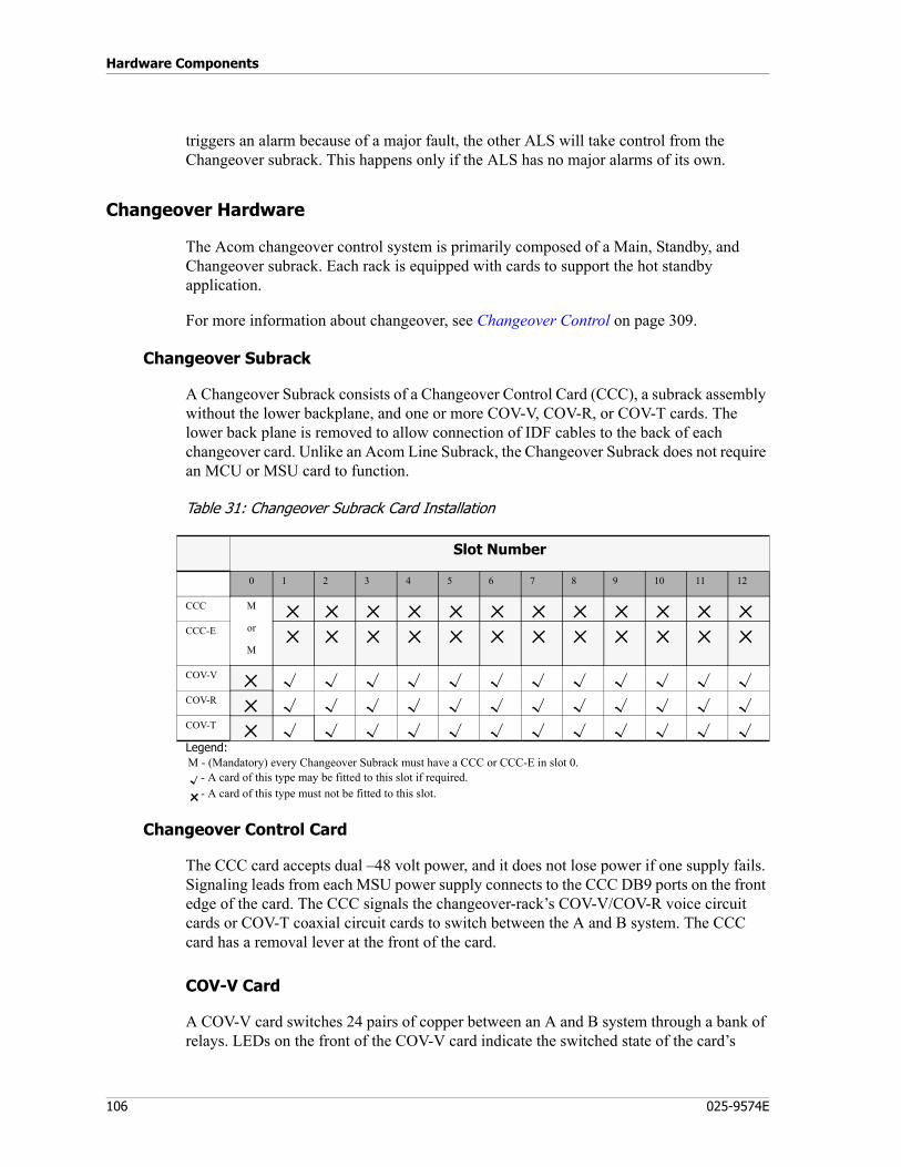
Hardware Components
106 025-9574E
triggers an alarm because of a major fault, the other ALS will take control from the Changeover subrack. This happens only if the ALS has no major alarms of its own.
Changeover Hardware
The Acom changeover control system is primarily composed of a Main, Standby, and Changeover subrack. Each rack is equipped with cards to support the hot standby application.
For more information about changeover, see Changeover Control on page 309.
Changeover Subrack
A Changeover Subrack consists of a Changeover Control Card (CCC), a subrack assembly without the lower backplane, and one or more COV-V, COV-R, or COV-T cards. The lower back plane is removed to allow connection of IDF cables to the back of each changeover card. Unlike an Acom Line Subrack, the Changeover Subrack does not require an MCU or MSU card to function.
Table 31: Changeover Subrack Card Installation
Legend:M - (Mandatory) every Changeover Subrack must have a CCC or CCC-E in slot 0.
- A card of this type may be fitted to this slot if required.- A card of this type must not be fitted to this slot.
Changeover Control Card
The CCC card accepts dual –48 volt power, and it does not lose power if one supply fails. Signaling leads from each MSU power supply connects to the CCC DB9 ports on the front edge of the card. The CCC signals the changeover-rack’s COV-V/COV-R voice circuit cards or COV-T coaxial circuit cards to switch between the A and B system. The CCC card has a removal lever at the front of the card.
COV-V Card
A COV-V card switches 24 pairs of copper between an A and B system through a bank of relays. LEDs on the front of the COV-V card indicate the switched state of the card’s
Slot Number
0 1 2 3 4 5 6 7 8 9 10 11 12
CCC M
or
M
CCC-E
COV-V
COV-R
COV-T
107
Changeover Subrack
relays. An LED on the front of the COV-V card indicates if it is receiving power from the CCC card.
If a relay on the COV-V card fails, it will probably fail in either the A or B state. If both subracks are operating, the failure may go unnoticed. Each of the six LEDs on the front of the card reflects the switched state for two of the 12 relays on the COV-V card.
Inputs from the A ALS are connected to the top connector P2 of the COV-V card. Inputs from the B ALS are connected to the bottom connector P3 of the COV-V card. The common outputs of the COV-V card are connected to the back connector P1 and are terminated at an IDF for connection to a resource.
The COV-V card is not equipped with a removal lever at the top of the card.
COV-R Card
The COV-R card is functionally identical to the COV-V card. The primary difference is that the COV-R card uses RJ-21 connectors for A system, B system, and the common connector at the rear. Due to its smaller connectors, the COV-R card has a removal lever on the front of the card.
COV-T Card
A COV-T card switches three sets of coaxial links between an A and B system. This card is typically used to switch E1 or ISDN links from the CO between the A and B rack. It is not used to switch E1 links between subracks and DS3 Switch, nor a Acom Console Unit and DS3 Switch. These connections are already redundant and do not need to pass through a changeover card.
The common pair of coaxial lines connects to the top connector on each of the three connection sets. The first set of connections is on the top front of the COV-T card. The top pair is the common; the second pair is the “A” side, and the third pair is the “B” side. Just below these coaxial connections are the second set with a similar order. The third set of coaxial links is connected to the rear of the COV-T card. Unlike the COV-V and COV-R cards, the common connections on a COV-T are not made through the back; instead there are two common sets of connections on the front of the card, and one on the back.
The COV-T card is not equipped with a removal lever at the top of the card.
Card placement
The CCC card must be located in slot 0 of the changeover cabinet. The COV-V, COV-R, and COV-T cards should be located in slots 1 through 12 of the Changeover Subrack.
Additional Hardware
The common connections secure to the back of the rack and changeover cards using screw terminal connections. Care should be taken to verify the card seats completely into the back cable. Use of spacers may be required to get a secure connection.
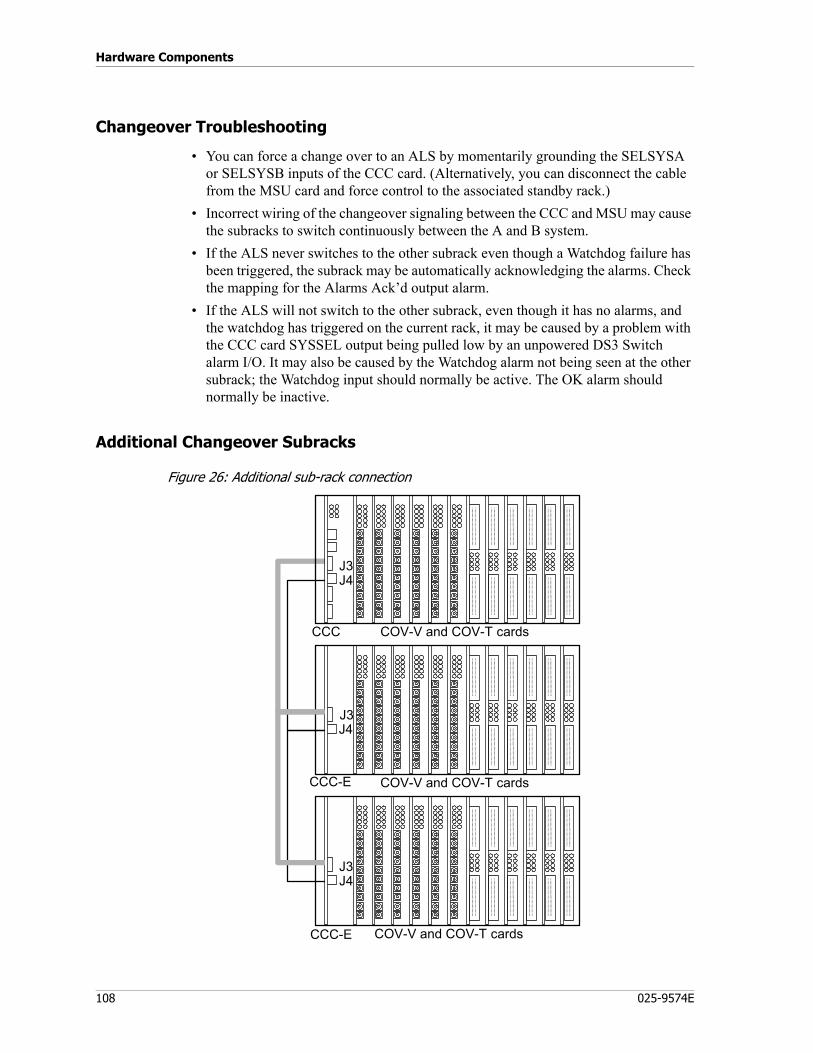
Hardware Components
108 025-9574E
Changeover Troubleshooting
• You can force a change over to an ALS by momentarily grounding the SELSYSA or SELSYSB inputs of the CCC card. (Alternatively, you can disconnect the cable from the MSU card and force control to the associated standby rack.)
• Incorrect wiring of the changeover signaling between the CCC and MSU may cause the subracks to switch continuously between the A and B system.
• If the ALS never switches to the other subrack even though a Watchdog failure has been triggered, the subrack may be automatically acknowledging the alarms. Check the mapping for the Alarms Ack’d output alarm.
• If the ALS will not switch to the other subrack, even though it has no alarms, and the watchdog has triggered on the current rack, it may be caused by a problem with the CCC card SYSSEL output being pulled low by an unpowered DS3 Switch alarm I/O. It may also be caused by the Watchdog alarm not being seen at the other subrack; the Watchdog input should normally be active. The OK alarm should normally be inactive.
Additional Changeover Subracks
Figure 26: Additional sub-rack connection
J4J3
J4J3
J4J3
COV-V and COV-T cards
COV-V and COV-T cards
COV-V and COV-T cards
CCC-E
CCC-E
CCC

109
Changeover Subrack
Where more than one subrack is required to house all the COV cards involved in the change over, they are connected to the first subrack by a jumper cable between the two common connectors J3 and J4 as shown in Figure 26.

Hardware Components
110 025-9574E
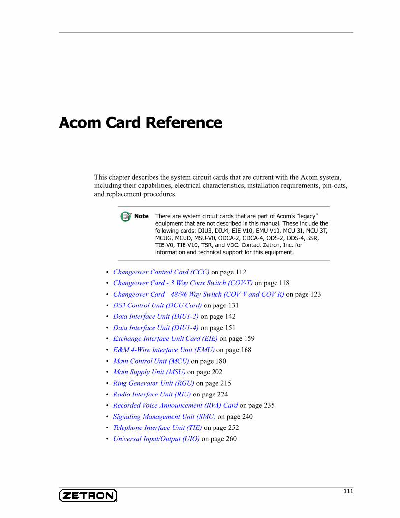
111
Acom Card Reference
This chapter describes the system circuit cards that are current with the Acom system, including their capabilities, electrical characteristics, installation requirements, pin-outs, and replacement procedures.
• Changeover Control Card (CCC) on page 112• Changeover Card - 3 Way Coax Switch (COV-T) on page 118• Changeover Card - 48/96 Way Switch (COV-V and COV-R) on page 123• DS3 Control Unit (DCU Card) on page 131• Data Interface Unit (DIU1-2) on page 142• Data Interface Unit (DIU1-4) on page 151• Exchange Interface Unit Card (EIE) on page 159• E&M 4-Wire Interface Unit (EMU) on page 168• Main Control Unit (MCU) on page 180• Main Supply Unit (MSU) on page 202• Ring Generator Unit (RGU) on page 215• Radio Interface Unit (RIU) on page 224• Recorded Voice Announcement (RVA) Card on page 235• Signaling Management Unit (SMU) on page 240• Telephone Interface Unit (TIE) on page 252• Universal Input/Output (UIO) on page 260
Note There are system circuit cards that are part of Acom’s “legacy” equipment that are not described in this manual. These include the following cards: DIU3, DIU4, EIE V10, EMU V10, MCU 3I, MCU 3T, MCUG, MCUD, MSU-V0, ODCA-2, ODCA-4, ODS-2, ODS-4, SSR, TIE-V0, TIE-V10, TSR, and VDC. Contact Zetron, Inc. for information and technical support for this equipment.

Acom Card Reference
112 025-9574E
Changeover Control Card (CCC)
P/N 950-0492
The Changeover Control Card (CCC) is mounted in a separate sub-rack than the standard Acom system cards and controls the switching between a primary and standby Acom system. All of the primary Acom switching facilities can be duplicated in adjoining sub-racks.
The card monitors the status of two Acom systems by a connection to the Main Supply Unit (MSU) for the system. In the event that the Primary system fails, the MSU signals the CCC to change from the primary to the standby system. The CCC then drives the changeover performed by the Changeover Card - 48/96 Way Switch (COV-V or COV-R) and Changeover Card - 3 Way Coaxial Switch (COV-T) cards. These cards change the external signal lines before the lines reach any line cards of the Acom switch.
The CCC has the following features:• Initiates changeover of COV cards on command from the primary or standby Acom
system.• Supports voice, data, or 2 Mb/s interfaces using COV cards.
The relationships between the Acom, the CCC, COV, and the standby line cards are shown in Figure 27
Figure 27: Standby Acom Configuration
The CCC is connected to the MSU alarm input and outputs on each Acom system. When one of the Acom systems has gained control, it provides an earth pulse of 20 ms or greater on the appropriate alarm output. This energizes a relay in the CCC and switches the externally supplied relay voltages through to the COV cards. The changeover relay is magnetically latched, and the selected state remains until changed by another alarm output. The currently selected system is fed back to each MSU through the alarm-input lines and is indicated on the CCC LEDs.
The CCC is used to switch between two functionally identical systems. These systems are referred to as the primary system and the standby system. Although there is no difference
Note In many applications the primary system and the standby systems are referred to respectively as System A and System B.
CCC
COVCOV
Acom
Acom
Terminal oroperator
equipment
Terminal oroperator
equipment
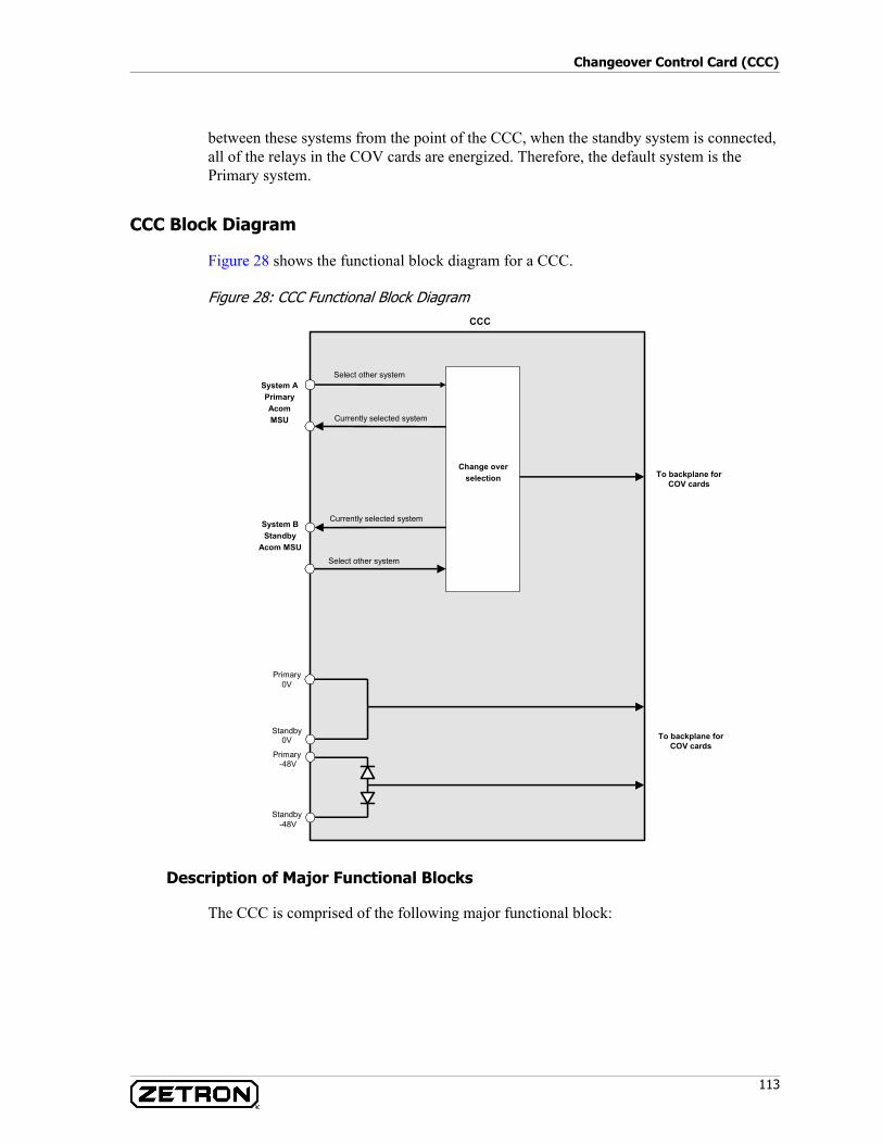
113
Changeover Control Card (CCC)
between these systems from the point of the CCC, when the standby system is connected, all of the relays in the COV cards are energized. Therefore, the default system is the Primary system.
CCC Block Diagram
Figure 28 shows the functional block diagram for a CCC.
Figure 28: CCC Functional Block Diagram
Description of Major Functional Blocks
The CCC is comprised of the following major functional block:
CCC
Select other system
Select other system
Currently selected system
Currently selected system
System APrimaryAcomMSU
System BStandby
Acom MSU
Change overselection
Standby -48V
Primary -48V
Standby0V
Primary0V
To backplane forCOV cards
To backplane forCOV cards
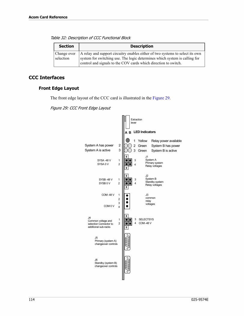
Acom Card Reference
114 025-9574E
Table 32: Description of CCC Functional Block
CCC Interfaces
Front Edge Layout
The front edge layout of the CCC card is illustrated in the Figure 29.
Figure 29: CCC Front Edge Layout
Section Description
Change over selection
A relay and support circuitry enables either of two systems to select its own system for switching use. The logic determines which system is calling for control and signals to the COV cards which direction to switch.
A B
System A has power 2System A is active 3
LED Indicators
1 Yellow Relay power available2 Green System B has power3 Green System B is active
Extractionlever
J1System APrimary systemRelay voltages
J2System BStandby systemRelay voltages
SYSA -48 VSYSA 0 V
COM -48 V
COM 0 V
J4Common voltage andselection Connector toadditional sub-racks
J3commonrelayvoltages
3
21
14
4
2
3
J5Primary (system A)changeover controls
J6Standby (system B)changeover controls
SYSB -48 VSYSB 0 V
3142
SELECTSYSCOM -48 V
3142
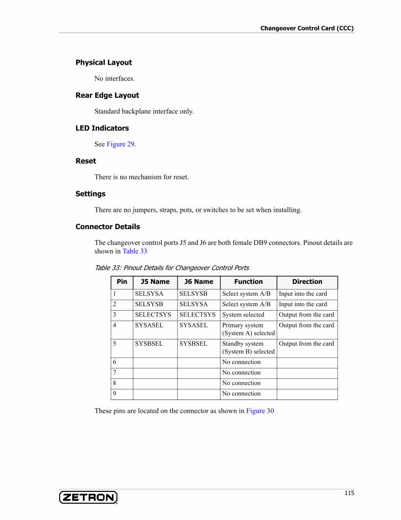
115
Changeover Control Card (CCC)
Physical Layout
No interfaces.
Rear Edge Layout
Standard backplane interface only.
LED Indicators
See Figure 29.
Reset
There is no mechanism for reset.
Settings
There are no jumpers, straps, pots, or switches to be set when installing.
Connector Details
The changeover control ports J5 and J6 are both female DB9 connectors. Pinout details are shown in Table 33
Table 33: Pinout Details for Changeover Control Ports
These pins are located on the connector as shown in Figure 30
Pin J5 Name J6 Name Function Direction
1 SELSYSA SELSYSB Select system A/B Input into the card2 SELSYSB SELSYSA Select system A/B Input into the card3 SELECTSYS SELECTSYS System selected Output from the card4 SYSASEL SYSASEL Primary system
(System A) selectedOutput from the card
5 SYSBSEL SYSBSEL Standby system (System B) selected
Output from the card
6 No connection7 No connection8 No connection9 No connection
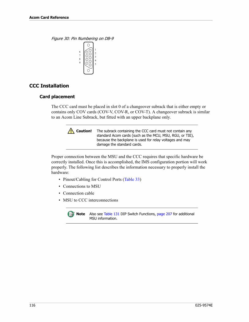
Acom Card Reference
116 025-9574E
Figure 30: Pin Numbering on DB-9
CCC Installation
Card placement
The CCC card must be placed in slot 0 of a changeover subrack that is either empty or contains only COV cards (COV-V, COV-R, or COV-T). A changeover subrack is similar to an Acom Line Subrack, but fitted with an upper backplane only.
Proper connection between the MSU and the CCC requires that specific hardware be correctly installed. Once this is accomplished, the IMS configuration portion will work properly. The following list describes the information necessary to properly install the hardware:
• Pinout/Cabling for Control Ports (Table 33)• Connections to MSU• Connection cable• MSU to CCC interconnections
6789
12345
Caution! The subrack containing the CCC card must not contain any standard Acom cards (such as the MCU, MSU, RGU, or TIE), because the backplane is used for relay voltages and may damage the standard cards.
Note Also see Table 131 DIP Switch Functions, page 207 for additional MSU information.
!
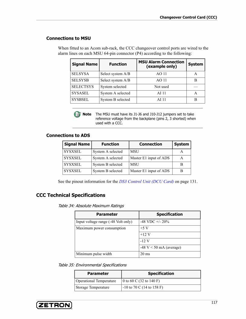
117
Changeover Control Card (CCC)
Connections to MSU
When fitted to an Acom sub-rack, the CCC changeover control ports are wired to the alarm lines on each MSU 64-pin connector (P4) according to the following:
Connections to ADS
See the pinout information for the DS3 Control Unit (DCU Card) on page 131.
CCC Technical Specifications
Table 34: Absolute Maximum Ratings
Table 35: Environmental Specifications
Signal Name Function MSU Alarm Connection (example only) System
SELSYSA Select system A/B AO 11 ASELSYSB Select system A/B AO 11 BSELECTSYS System selected Not used —SYSASEL System A selected AI 11 ASYSBSEL System B selected AI 11 B
Note The MSU must have its J1-J6 and J10-J12 jumpers set to take reference voltage from the backplane (pins 2, 3 shorted) when used with a CCC.
Signal Name Function Connection System
SYSXSEL System A selected MSU ASYSXSEL System A selected Master E1 input of ADS ASYSXSEL System B selected MSU BSYSXSEL System B selected Master E1 input of ADS B
Parameter Specification
Input voltage range (-48 Volt only) -48 VDC +/- 20%Maximum power consumption +5 V
+12 V-12 V-48 V < 50 mA (average)
Minimum pulse width 20 ms
Parameter Specification
Operational Temperature 0 to 60 C (32 to 140 F)Storage Temperature -10 to 70 C (14 to 158 F)
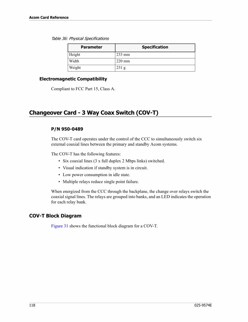
Acom Card Reference
118 025-9574E
Table 36: Physical Specifications
Electromagnetic Compatibility
Compliant to FCC Part 15, Class A.
Changeover Card - 3 Way Coax Switch (COV-T)
P/N 950-0489
The COV-T card operates under the control of the CCC to simultaneously switch six external coaxial lines between the primary and standby Acom systems.
The COV-T has the following features:• Six coaxial lines (3 x full duplex 2 Mbps links) switched.• Visual indication if standby system is in circuit.• Low power consumption in idle state.• Multiple relays reduce single point failure.
When energized from the CCC through the backplane, the change over relays switch the coaxial signal lines. The relays are grouped into banks, and an LED indicates the operation for each relay bank.
COV-T Block Diagram
Figure 31 shows the functional block diagram for a COV-T.
Parameter Specification
Height 233 mmWidth 220 mmWeight 231 g
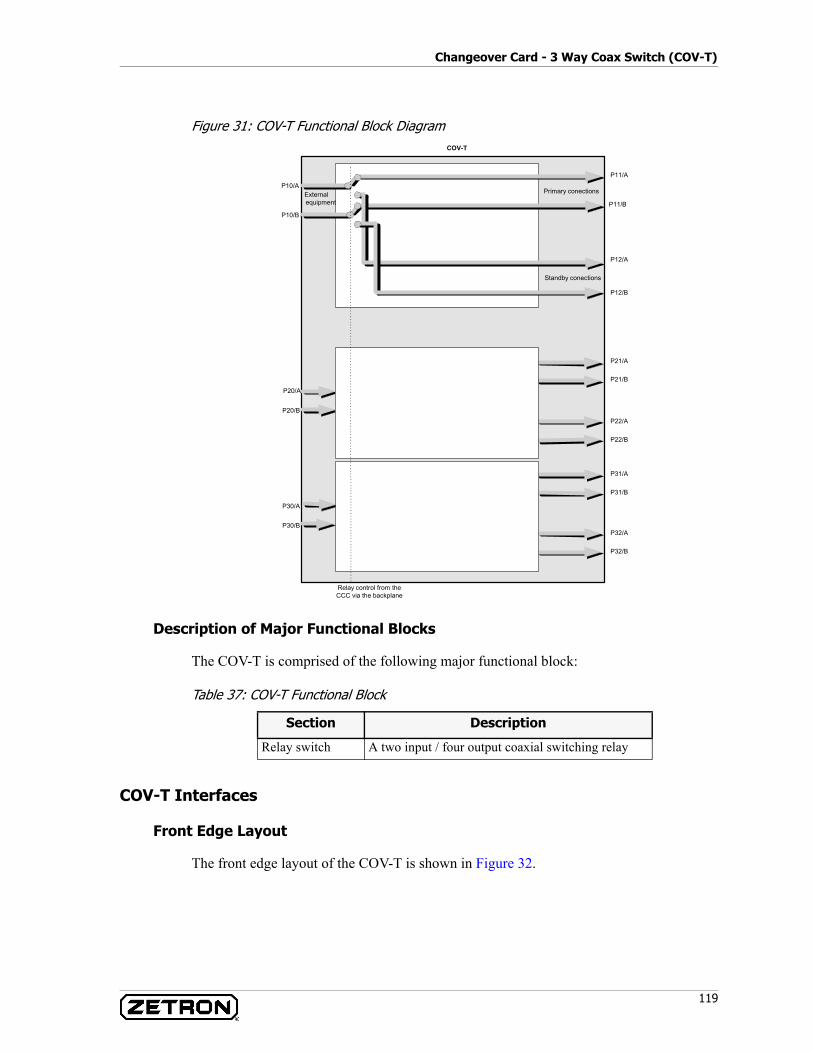
119
Changeover Card - 3 Way Coax Switch (COV-T)
Figure 31: COV-T Functional Block Diagram
Description of Major Functional Blocks
The COV-T is comprised of the following major functional block:
Table 37: COV-T Functional Block
COV-T Interfaces
Front Edge Layout
The front edge layout of the COV-T is shown in Figure 32.
COV-T
P10/B
P12/B
P12/A
P11/A
P11/B
P10/APrimary conections
Standby conections
P20/A
P20/B
P30/A
P30/B
Relay control from theCCC via the backplane
Externalequipment
P22/B
P22/A
P21/A
P21/B
P32/B
P32/A
P31/A
P31/B
Section Description
Relay switch A two input / four output coaxial switching relay
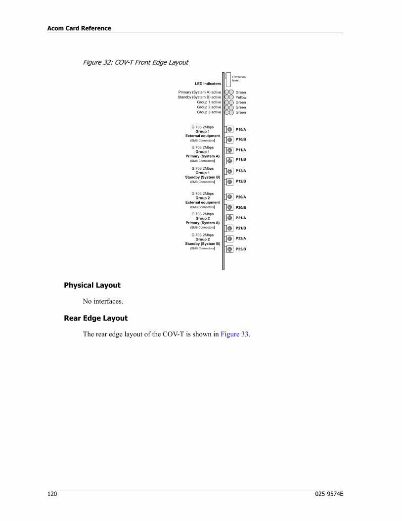
Acom Card Reference
120 025-9574E
Figure 32: COV-T Front Edge Layout
Physical Layout
No interfaces.
Rear Edge Layout
The rear edge layout of the COV-T is shown in Figure 33.
Extractionlever
LED Indicators
Primary (System A) activeStandby (System B) active
Group 1 activeGroup 2 activeGroup 3 active
GreenYellowGreenGreenGreen
P10/A
G.703 2MbpsGroup 1
Standby (System B)(SMB Connectors)
G.703 2MbpsGroup 1
Primary (System A)(SMB Connectors)
G.703 2MbpsGroup 1
External equipment(SMB Connectors) P10/B
P11/A
P11/B
P12/A
P12/B
P20/A
P20/B
P21/A
P21/B
P22/A
P22/B
G.703 2MbpsGroup 2
Standby (System B)(SMB Connectors)
G.703 2MbpsGroup 2
Primary (System A)(SMB Connectors)
G.703 2MbpsGroup 2
External equipment(SMB Connectors)
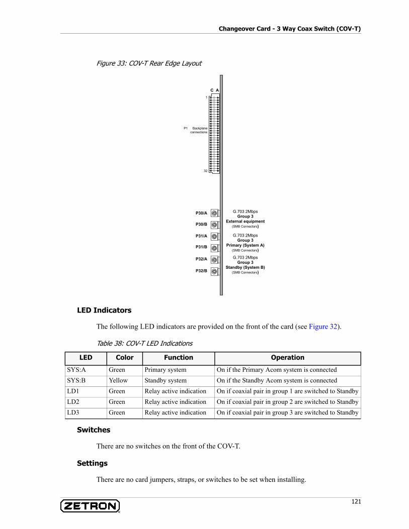
121
Changeover Card - 3 Way Coax Switch (COV-T)
Figure 33: COV-T Rear Edge Layout
LED Indicators
The following LED indicators are provided on the front of the card (see Figure 32).
Table 38: COV-T LED Indications
Switches
There are no switches on the front of the COV-T.
Settings
There are no card jumpers, straps, or switches to be set when installing.
P30/A
P30/B
P31/A
P31/B
P32/A
P32/B
G.703 2MbpsGroup 3
Standby (System B)(SMB Connectors)
G.703 2MbpsGroup 3
Primary (System A)(SMB Connectors)
G.703 2MbpsGroup 3
External equipment(SMB Connectors)
C A1
P1 Backplane connections
32
LED Color Function Operation
SYS:A Green Primary system On if the Primary Acom system is connectedSYS:B Yellow Standby system On if the Standby Acom system is connectedLD1 Green Relay active indication On if coaxial pair in group 1 are switched to StandbyLD2 Green Relay active indication On if coaxial pair in group 2 are switched to StandbyLD3 Green Relay active indication On if coaxial pair in group 3 are switched to Standby
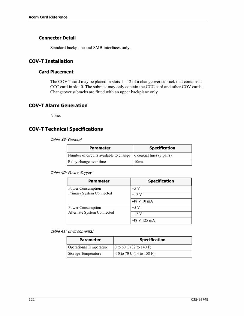
Acom Card Reference
122 025-9574E
Connector Detail
Standard backplane and SMB interfaces only.
COV-T Installation
Card Placement
The COV-T card may be placed in slots 1 - 12 of a changeover subrack that contains a CCC card in slot 0. The subrack may only contain the CCC card and other COV cards. Changeover subracks are fitted with an upper backplane only.
COV-T Alarm Generation
None.
COV-T Technical Specifications
Table 39: General
Table 40: Power Supply
Table 41: Environmental
Parameter Specification
Number of circuits available to change 6 coaxial lines (3 pairs)Relay change over time 10ms
Parameter Specification
Power ConsumptionPrimary System Connected
+5 V+12 V-48 V 10 mA
Power ConsumptionAlternate System Connected
+5 V+12 V-48 V 125 mA
Parameter Specification
Operational Temperature 0 to 60 C (32 to 140 F)Storage Temperature -10 to 70 C (14 to 158 F)
123
Changeover Card - 48/96 Way Switch (COV-V and COV-R)
Table 42: Physical
Electromagnetic Compatibility
Compliant to FCC Part 15, Class A.
Changeover Card - 48/96 Way Switch (COV-V and COV-R)
P/N COV-V 950-0488P/N COV-R 950-0837
The COV-V and COV-R cards operate under the control of the CCC to simultaneously switch 48 external signal lines (24 pairs) between a primary and standby Acom system.
The COV-V and COV-R have the following features:• 48 signal lines switched (24 signal pairs). These may be used for switching standard
VF, data, or contact closures.• Visual indication if standby system is in circuit.• Low power consumption in idle state.• Multiple relays reduce single point failure.
Energized from the CCC through the backplane, the changeover relays switch the 2 x 2 wire signal lines. The relays are grouped into banks, and each bank of energized relays is indicated by an LED. To switch back to the original system, the relays are de-energized.
COV-V and COV-R Block Diagram
Figure 34 shows the functional block diagram for a COV-V or COV-R.
Parameter Specification
Height 233 mmWidth 220 mmWeight 278 g
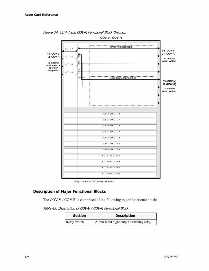
Acom Card Reference
124 025-9574E
Figure 34: COV-V and COV-R Functional Block Diagram
Description of Major Functional Blocks
The COV-V / COV-R is comprised of the following major functional block:
Table 43: Description of COV-V / COV-R Functional Block
To externalequipment or
operatorequipment
COV-V / COV-R
CCT5-1 to CCT5-4
CCT4-5 to CCT 4-8
CCT4-1 to CCT 4-4
CCT3-5 to CCT 3-8
CCT3-1 to CCT 3-4
CCT2-5 to CCT 2-8
CCT2-1 to CCT 2-4
CCT1-5 to CCT 1-8
CCT 1-4
CCT 1-3
CCT 1-2
CCT 1-1
CCT5-5 to CCT5-8
CCT6-1 to CCT6-4
CCT6-5 to CCT6-8
Primary connections
Secondary connections
P2 (COV-V)J1 (COV-R)P4 (COV-V)
P2 (COV-R)
Relay control from CCC through backplane
To primaryAcom system
To standbyAcom system
P3 (COV-V)J2 (COV-R)
Section Description
Relay switch A four input eight output switching relay.
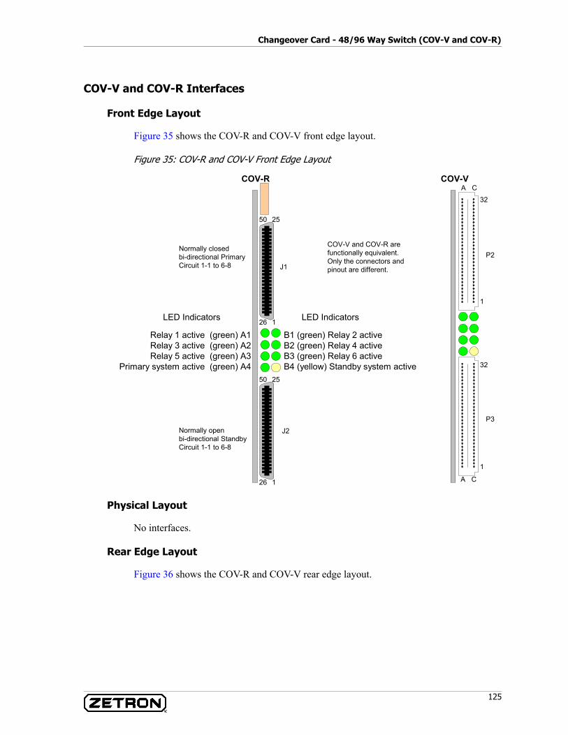
125
Changeover Card - 48/96 Way Switch (COV-V and COV-R)
COV-V and COV-R Interfaces
Front Edge Layout
Figure 35 shows the COV-R and COV-V front edge layout.
Figure 35: COV-R and COV-V Front Edge Layout
Physical Layout
No interfaces.
Rear Edge Layout
Figure 36 shows the COV-R and COV-V rear edge layout.
COV-R
B1 (green) Relay 2 activeB2 (green) Relay 4 activeB3 (green) Relay 6 activeB4 (yellow) Standby system active
Relay 1 active (green) A1Relay 3 active (green) A2Relay 5 active (green) A3
Primary system active (green) A4
LED IndicatorsLED Indicators
25
1
50
26
25
1
50
26
Normally closedbi-directional PrimaryCircuit 1-1 to 6-8
Normally openbi-directional StandbyCircuit 1-1 to 6-8
32
1
A CCOV-V
COV-V and COV-R arefunctionally equivalent.Only the connectors andpinout are different.
32
1
A C
P2
P3
J2
J1

Acom Card Reference
126 025-9574E
Figure 36: COV-R and COV-V Rear Edge Layout
LED Indicators
The following LED indicators are provided on the front of the card (see Figure 35).
Table 44: LED Indicators
COV-R
Bi-directional PrimaryCircuit 1-1 to 6-8
32
1C A
COV-V
COV-V and COV-R arefunctionally equivalent.Only the connectors andpinout are different.
32
1
C A
P1
P4
25
1
50
26
P2
Backplane Connections
32
1C A
P1
LED Color Function Operation
A1 Green Relay active indication On if circuit 1-1 to 1-8 are switched to standbyB1 Green Relay active indication On if circuit 2-1 to 2-8 are switched to standbyA2 Green Relay active indication On if circuit 3-1 to 3-8 are switched to standbyB2 Green Relay active indication On if circuit 4-1 to 4-8 are switched to standbyA3 Green Relay active indication On if circuit 5-1 to 5-8 are switched to standbyB3 Green Relay active indication On if circuit 6-1 to 6-8 are switched to standbyA4 Green Primary system On if the primary Acom system is connectedB4 Yellow Standby system On if the standby Acom system is connected
127
Changeover Card - 48/96 Way Switch (COV-V and COV-R)
Settings
When installing a COV-V / COV-R card there are no settings, jumpers, pots, straps, or switches to be set.
COV-V Connector Detail
(For COV-R card pinout, see Table 46 on page 129.)
Table 45 shows the pinout cable connections for P4, P2 and P3 on the COV-V card. Cabling is done so that the cable terminating into connector P4 can be plugged directly into either of the cables terminating into P2 or P3, removing the COV-V card from the circuit. Mounting P4 upside down relative to either P2 or P3 means that pin 1a of P4 will connect to pin 32a of P2 or P3 if the two cables were connected directly.
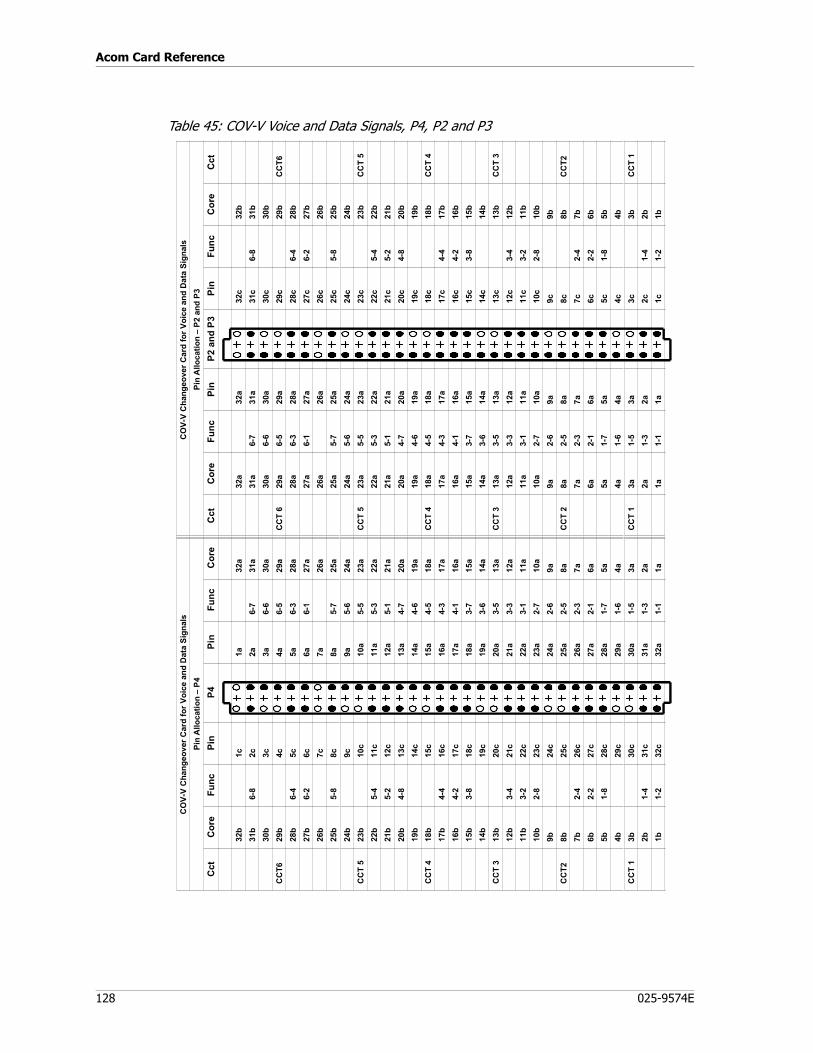
Acom Card Reference
128 025-9574E
Table 45: COV-V Voice and Data Signals, P4, P2 and P3
CO
V-V
Cha
ngeo
ver C
ard
for V
oice
and
Dat
a Si
gnal
sC
OV-
V C
hang
eove
r Car
d fo
r Voi
ce a
nd D
ata
Sign
als
Pin
Allo
catio
n –
P4Pi
n A
lloca
tion
– P2
and
P3
Cct
Cor
eFu
ncPi
nP4
Pin
Func
Cor
eC
ctC
ore
Func
Pin
P2 a
nd P
3Pi
nFu
ncC
ore
Cct
32b
1c1a
32a
32a
32a
32c
32b
31b
6-8
2c2a
6-7
31a
31a
6-7
31a
31c
6-8
31b
30b
3c3a
6-6
30a
30a
6-6
30a
30c
30b
CC
T629
b4c
4a6-
529
aC
CT
629
a6-
529
a29
c29
bC
CT6
28b
6-4
5c5a
6-3
28a
28a
6-3
28a
28c
6-4
28b
27b
6-2
6c6a
6-1
27a
27a
6-1
27a
27c
6-2
27b
26b
7c7a
26a
26a
26a
26c
26b
25b
5-8
8c8a
5-7
25a
25a
5-7
25a
25c
5-8
25b
24b
9c9a
5-6
24a
24a
5-6
24a
24c
24b
CC
T 5
23b
10c
10a
5-5
23a
CC
T 5
23a
5-5
23a
23c
23b
CC
T 5
22b
5-4
11c
11a
5-3
22a
22a
5-3
22a
22c
5-4
22b
21b
5-2
12c
12a
5-1
21a
21a
5-1
21a
21c
5-2
21b
20b
4-8
13c
13a
4-7
20a
20a
4-7
20a
20c
4-8
20b
19b
14c
14a
4-6
19a
19a
4-6
19a
19c
19b
CC
T 4
18b
15c
15a
4-5
18a
CC
T 4
18a
4-5
18a
18c
18b
CC
T 4
17b
4-4
16c
16a
4-3
17a
17a
4-3
17a
17c
4-4
17b
16b
4-2
17c
17a
4-1
16a
16a
4-1
16a
16c
4-2
16b
15b
3-8
18c
18a
3-7
15a
15a
3-7
15a
15c
3-8
15b
14b
19c
19a
3-6
14a
14a
3-6
14a
14c
14b
CC
T 3
13b
20c
20a
3-5
13a
CC
T 3
13a
3-5
13a
13c
13b
CC
T 3
12b
3-4
21c
21a
3-3
12a
12a
3-3
12a
12c
3-4
12b
11b
3-2
22c
22a
3-1
11a
11a
3-1
11a
11c
3-2
11b
10b
2-8
23c
23a
2-7
10a
10a
2-7
10a
10c
2-8
10b
9b24
c24
a2-
69a
9a2-
69a
9c9b
CC
T28b
25c
25a
2-5
8aC
CT
28a
2-5
8a8c
8bC
CT2
7b2-
426
c26
a2-
37a
7a2-
37a
7c2-
47b
6b2-
227
c27
a2-
16a
6a2-
16a
6c2-
26b
5b1-
828
c28
a1-
75a
5a1-
75a
5c1-
85b
4b29
c29
a1-
64a
4a1-
64a
4c4b
CC
T 1
3b30
c30
a1-
53a
CC
T 1
3a1-
53a
3c3b
CC
T 1
2b1-
431
c31
a1-
32a
2a1-
32a
2c1-
42b
1b1-
232
c32
a1-
11a
1a1-
11a
1c1-
21b
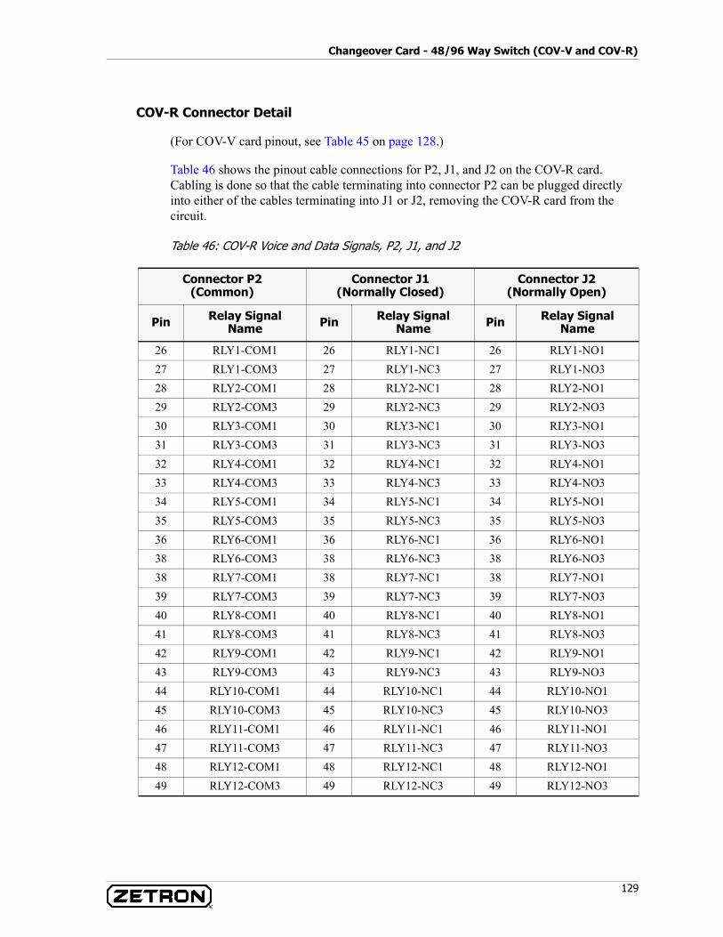
129
Changeover Card - 48/96 Way Switch (COV-V and COV-R)
COV-R Connector Detail
(For COV-V card pinout, see Table 45 on page 128.)
Table 46 shows the pinout cable connections for P2, J1, and J2 on the COV-R card. Cabling is done so that the cable terminating into connector P2 can be plugged directly into either of the cables terminating into J1 or J2, removing the COV-R card from the circuit.
Table 46: COV-R Voice and Data Signals, P2, J1, and J2
Connector P2(Common)
Connector J1(Normally Closed)
Connector J2(Normally Open)
Pin Relay Signal Name Pin Relay Signal
Name Pin Relay Signal Name
26 RLY1-COM1 26 RLY1-NC1 26 RLY1-NO127 RLY1-COM3 27 RLY1-NC3 27 RLY1-NO328 RLY2-COM1 28 RLY2-NC1 28 RLY2-NO129 RLY2-COM3 29 RLY2-NC3 29 RLY2-NO330 RLY3-COM1 30 RLY3-NC1 30 RLY3-NO131 RLY3-COM3 31 RLY3-NC3 31 RLY3-NO332 RLY4-COM1 32 RLY4-NC1 32 RLY4-NO133 RLY4-COM3 33 RLY4-NC3 33 RLY4-NO334 RLY5-COM1 34 RLY5-NC1 34 RLY5-NO135 RLY5-COM3 35 RLY5-NC3 35 RLY5-NO336 RLY6-COM1 36 RLY6-NC1 36 RLY6-NO138 RLY6-COM3 38 RLY6-NC3 38 RLY6-NO338 RLY7-COM1 38 RLY7-NC1 38 RLY7-NO139 RLY7-COM3 39 RLY7-NC3 39 RLY7-NO340 RLY8-COM1 40 RLY8-NC1 40 RLY8-NO141 RLY8-COM3 41 RLY8-NC3 41 RLY8-NO342 RLY9-COM1 42 RLY9-NC1 42 RLY9-NO143 RLY9-COM3 43 RLY9-NC3 43 RLY9-NO344 RLY10-COM1 44 RLY10-NC1 44 RLY10-NO145 RLY10-COM3 45 RLY10-NC3 45 RLY10-NO346 RLY11-COM1 46 RLY11-NC1 46 RLY11-NO147 RLY11-COM3 47 RLY11-NC3 47 RLY11-NO348 RLY12-COM1 48 RLY12-NC1 48 RLY12-NO149 RLY12-COM3 49 RLY12-NC3 49 RLY12-NO3
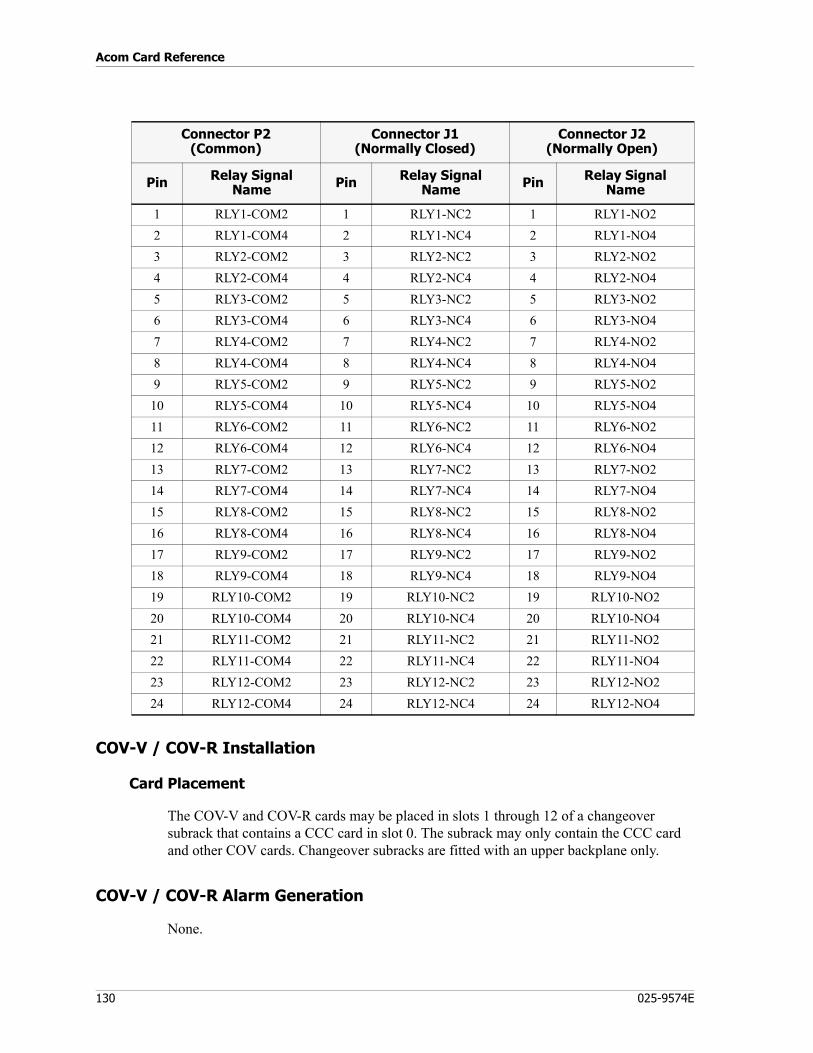
Acom Card Reference
130 025-9574E
COV-V / COV-R Installation
Card Placement
The COV-V and COV-R cards may be placed in slots 1 through 12 of a changeover subrack that contains a CCC card in slot 0. The subrack may only contain the CCC card and other COV cards. Changeover subracks are fitted with an upper backplane only.
COV-V / COV-R Alarm Generation
None.
1 RLY1-COM2 1 RLY1-NC2 1 RLY1-NO22 RLY1-COM4 2 RLY1-NC4 2 RLY1-NO43 RLY2-COM2 3 RLY2-NC2 3 RLY2-NO24 RLY2-COM4 4 RLY2-NC4 4 RLY2-NO45 RLY3-COM2 5 RLY3-NC2 5 RLY3-NO26 RLY3-COM4 6 RLY3-NC4 6 RLY3-NO47 RLY4-COM2 7 RLY4-NC2 7 RLY4-NO28 RLY4-COM4 8 RLY4-NC4 8 RLY4-NO49 RLY5-COM2 9 RLY5-NC2 9 RLY5-NO2
10 RLY5-COM4 10 RLY5-NC4 10 RLY5-NO411 RLY6-COM2 11 RLY6-NC2 11 RLY6-NO212 RLY6-COM4 12 RLY6-NC4 12 RLY6-NO413 RLY7-COM2 13 RLY7-NC2 13 RLY7-NO214 RLY7-COM4 14 RLY7-NC4 14 RLY7-NO415 RLY8-COM2 15 RLY8-NC2 15 RLY8-NO216 RLY8-COM4 16 RLY8-NC4 16 RLY8-NO417 RLY9-COM2 17 RLY9-NC2 17 RLY9-NO218 RLY9-COM4 18 RLY9-NC4 18 RLY9-NO419 RLY10-COM2 19 RLY10-NC2 19 RLY10-NO220 RLY10-COM4 20 RLY10-NC4 20 RLY10-NO421 RLY11-COM2 21 RLY11-NC2 21 RLY11-NO222 RLY11-COM4 22 RLY11-NC4 22 RLY11-NO423 RLY12-COM2 23 RLY12-NC2 23 RLY12-NO224 RLY12-COM4 24 RLY12-NC4 24 RLY12-NO4
Connector P2(Common)
Connector J1(Normally Closed)
Connector J2(Normally Open)
Pin Relay Signal Name Pin Relay Signal
Name Pin Relay Signal Name
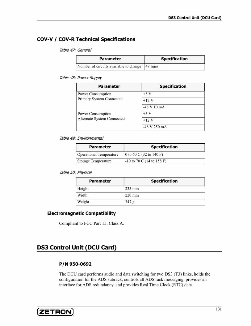
131
DS3 Control Unit (DCU Card)
COV-V / COV-R Technical Specifications
Table 47: General
Table 48: Power Supply
Table 49: Environmental
Table 50: Physical
Electromagnetic Compatibility
Compliant to FCC Part 15, Class A.
DS3 Control Unit (DCU Card)
P/N 950-0692
The DCU card performs audio and data switching for two DS3 (T3) links, holds the configuration for the ADS subrack, controls all ADS rack messaging, provides an interface for ADS redundancy, and provides Real Time Clock (RTC) data.
Parameter Specification
Number of circuits available to change 48 lines
Parameter Specification
Power ConsumptionPrimary System Connected
+5 V+12 V-48 V 10 mA
Power ConsumptionAlternate System Connected
+5 V+12 V-48 V 250 mA
Parameter Specification
Operational Temperature 0 to 60 C (32 to 140 F)Storage Temperature -10 to 70 C (14 to 158 F)
Parameter Specification
Height 233 mmWidth 220 mmWeight 347 g
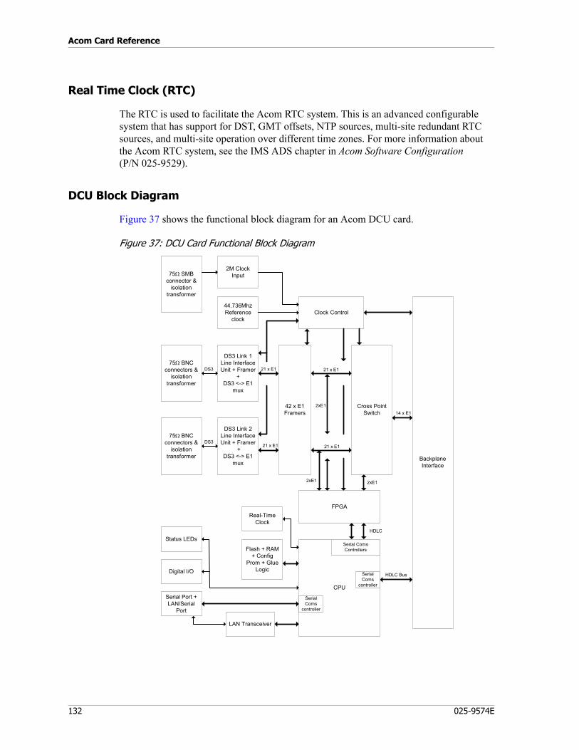
Acom Card Reference
132 025-9574E
Real Time Clock (RTC)
The RTC is used to facilitate the Acom RTC system. This is an advanced configurable system that has support for DST, GMT offsets, NTP sources, multi-site redundant RTC sources, and multi-site operation over different time zones. For more information about the Acom RTC system, see the IMS ADS chapter in Acom Software Configuration (P/N 025-9529).
DCU Block Diagram
Figure 37 shows the functional block diagram for an Acom DCU card.
Figure 37: DCU Card Functional Block Diagram
DS3 Link 1Line InterfaceUnit + Framer
+DS3 <-> E1
mux
DS3 Link 2Line InterfaceUnit + Framer
+DS3 <-> E1
mux
75Ω BNCconnectors &
isolationtransformer
75Ω BNCconnectors &
isolationtransformer
CPU
42 x E1Framers
Cross PointSwitch
44.736MhzReference
clock
Flash + RAM+ Config
Prom + GlueLogic
Serial Port +LAN/Serial
Port
DS3
DS3
21 x E1
21 x E1
2xE1
21 x E1
21 x E1
BackplaneInterface
HDLC Bus
14 x E1
Clock Control
Status LEDs
Digital I/O
Serial ComsControllers
SerialComs
controller
SerialComs
controller
75Ω SMBconnector &
isolationtransformer
2M ClockInput
FPGAReal-Time
Clock
LAN Transceiver
2xE1
2xE1
HDLC
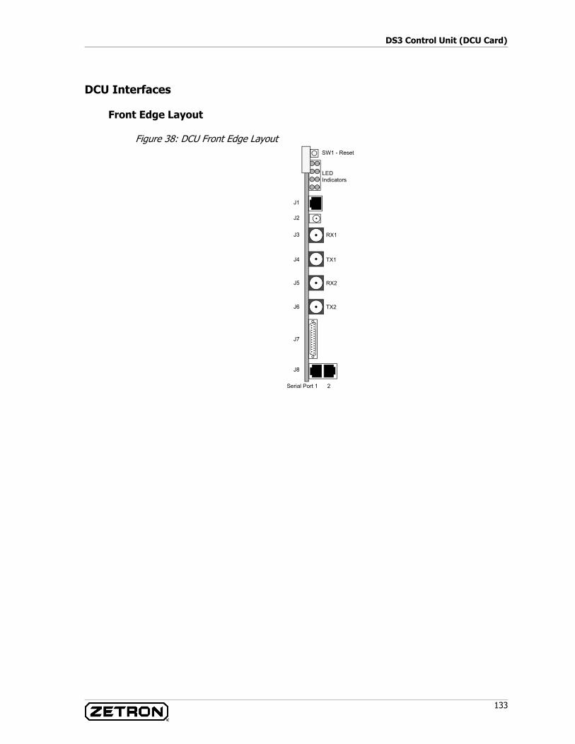
133
DS3 Control Unit (DCU Card)
DCU Interfaces
Front Edge Layout
Figure 38: DCU Front Edge Layout
J2
J1
J3
J4
J5
J6
J7
J8
LED Indicators
SW1 - Reset
RX1
TX1
RX2
TX2
Serial Port 1 2
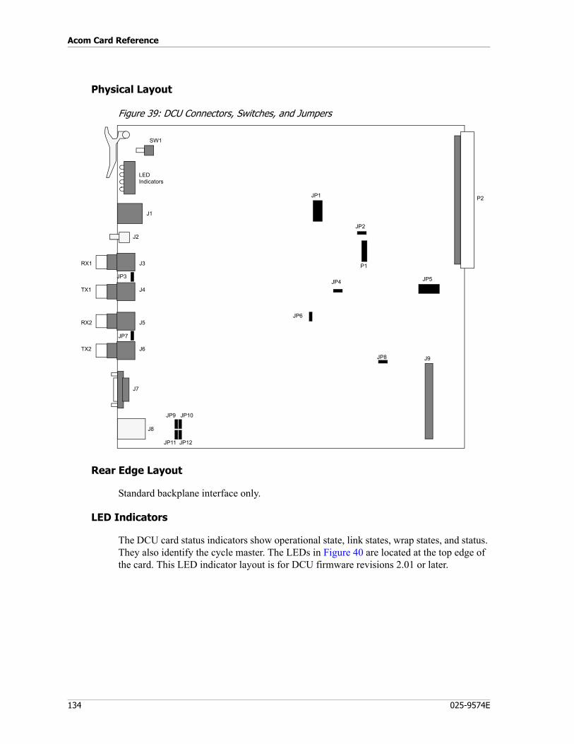
Acom Card Reference
134 025-9574E
Physical Layout
Figure 39: DCU Connectors, Switches, and Jumpers
Rear Edge Layout
Standard backplane interface only.
LED Indicators
The DCU card status indicators show operational state, link states, wrap states, and status. They also identify the cycle master. The LEDs in Figure 40 are located at the top edge of the card. This LED indicator layout is for DCU firmware revisions 2.01 or later.
SW1
J9
JP9 JP10
JP11 JP12
RX1
TX1
RX2
TX2
JP7
JP3
J3
J4
J5
J6
J1
J2
J7
J8
LED Indicators
JP4
JP6
JP8
JP2
JP1
JP5
P2
P1
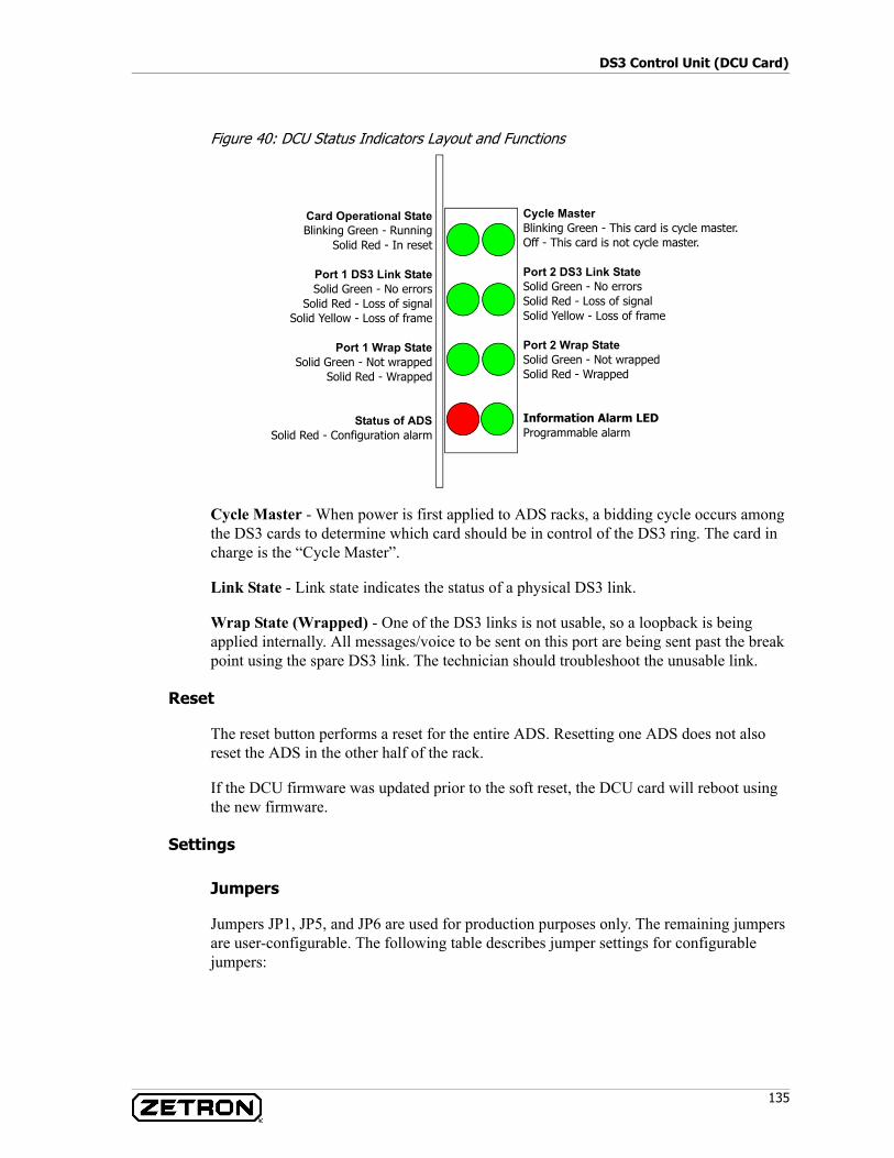
135
DS3 Control Unit (DCU Card)
Figure 40: DCU Status Indicators Layout and Functions
Cycle Master - When power is first applied to ADS racks, a bidding cycle occurs among the DS3 cards to determine which card should be in control of the DS3 ring. The card in charge is the “Cycle Master”.
Link State - Link state indicates the status of a physical DS3 link.
Wrap State (Wrapped) - One of the DS3 links is not usable, so a loopback is being applied internally. All messages/voice to be sent on this port are being sent past the break point using the spare DS3 link. The technician should troubleshoot the unusable link.
Reset
The reset button performs a reset for the entire ADS. Resetting one ADS does not also reset the ADS in the other half of the rack.
If the DCU firmware was updated prior to the soft reset, the DCU card will reboot using the new firmware.
Settings
Jumpers
Jumpers JP1, JP5, and JP6 are used for production purposes only. The remaining jumpers are user-configurable. The following table describes jumper settings for configurable jumpers:
Cycle MasterBlinking Green - This card is cycle master.Off - This card is not cycle master.
Port 2 DS3 Link StateSolid Green - No errorsSolid Red - Loss of signalSolid Yellow - Loss of frame
Port 2 Wrap StateSolid Green - Not wrappedSolid Red - Wrapped
Information Alarm LEDProgrammable alarm
Card Operational StateBlinking Green - Running
Solid Red - In reset
Port 1 DS3 Link StateSolid Green - No errors
Solid Red - Loss of signalSolid Yellow - Loss of frame
Port 1 Wrap StateSolid Green - Not wrapped
Solid Red - Wrapped
Status of ADSSolid Red - Configuration alarm

Acom Card Reference
136 025-9574E
Table 51: DCU Card Jumper Settings
Connector Detail
Connector J1 - Ethernet LAN Port
Connector J2 - External Clock Port
Jumper Position A (Pins 1-2) Position B (Pins 2-3)
JP2 Run card self-test during bootup. (Default)
Bypass card self-test during bootup.
JP4 Execute full version of code at startup. (Default)
Execute failsafe version of code at startup.
JP9 No resistive termination on serial port 1 receive pair. (Default)
120 ohm termination placed across serial port 1 receive pair.
JP10 No resistive termination on serial port 1 transmit pair. (Default)
120 ohm termination placed across serial port 1 transmit pair.
JP11 No resistive termination on serial port 2 transmit pair. (Default)
120 ohm termination placed across serial port 2 transmit pair.
JP12 No resistive termination on serial port 2 receive pair. (Default)
120 ohm termination placed across serial port 2 receive pair.
Jumper Installed (Pins 1-2) Not Installed
JP3 Grounds the shield of the DS3 receive port J3.
Leaves the shield of the DS3 receive port J3 not grounded. (Default)
JP7 Grounds the shield of the DS3 receive port J5.
Leaves the shield of the DS3 receive port J5 not grounded. (Default)
JP8 Allow the bootloader and failsafe codes to be overwritten.
Bootloader and failsafe code are write-protected. (Default)
Note The external serial clock, if implemented, is connected to serial port 2 (J8).
Pin 1: TX+Pin 2: TX-Pin 3: RX+
Pin 6: RX-
Outer conductor: Ground for clock input signal
Center: 2Mbps clock input signal
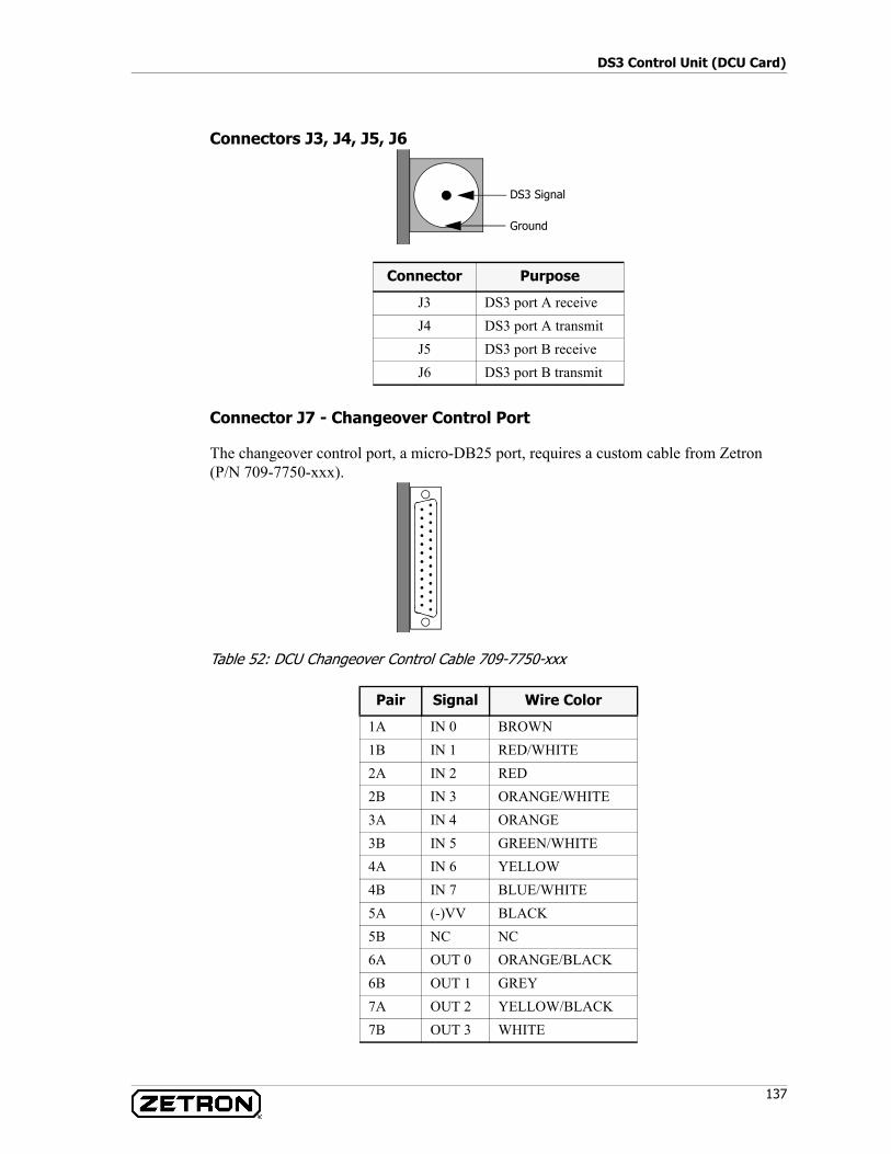
137
DS3 Control Unit (DCU Card)
Connectors J3, J4, J5, J6
Connector J7 - Changeover Control Port
The changeover control port, a micro-DB25 port, requires a custom cable from Zetron (P/N 709-7750-xxx).
Table 52: DCU Changeover Control Cable 709-7750-xxx
Connector Purpose
J3 DS3 port A receiveJ4 DS3 port A transmitJ5 DS3 port B receiveJ6 DS3 port B transmit
Pair Signal Wire Color
1A IN 0 BROWN1B IN 1 RED/WHITE2A IN 2 RED2B IN 3 ORANGE/WHITE3A IN 4 ORANGE3B IN 5 GREEN/WHITE4A IN 6 YELLOW4B IN 7 BLUE/WHITE5A (-)VV BLACK5B NC NC6A OUT 0 ORANGE/BLACK6B OUT 1 GREY7A OUT 2 YELLOW/BLACK7B OUT 3 WHITE
Ground
DS3 Signal
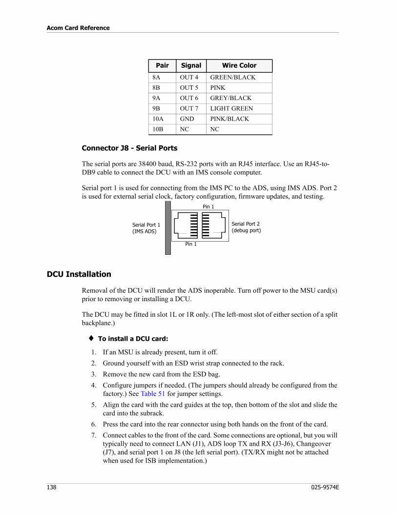
Acom Card Reference
138 025-9574E
Connector J8 - Serial Ports
The serial ports are 38400 baud, RS-232 ports with an RJ45 interface. Use an RJ45-to-DB9 cable to connect the DCU with an IMS console computer.
Serial port 1 is used for connecting from the IMS PC to the ADS, using IMS ADS. Port 2 is used for external serial clock, factory configuration, firmware updates, and testing.
DCU Installation
Removal of the DCU will render the ADS inoperable. Turn off power to the MSU card(s) prior to removing or installing a DCU.
The DCU may be fitted in slot 1L or 1R only. (The left-most slot of either section of a split backplane.)
♦ To install a DCU card:
1. If an MSU is already present, turn it off.2. Ground yourself with an ESD wrist strap connected to the rack.3. Remove the new card from the ESD bag.4. Configure jumpers if needed. (The jumpers should already be configured from the
factory.) See Table 51 for jumper settings.5. Align the card with the card guides at the top, then bottom of the slot and slide the
card into the subrack.6. Press the card into the rear connector using both hands on the front of the card.7. Connect cables to the front of the card. Some connections are optional, but you will
typically need to connect LAN (J1), ADS loop TX and RX (J3-J6), Changeover (J7), and serial port 1 on J8 (the left serial port). (TX/RX might not be attached when used for ISB implementation.)
8A OUT 4 GREEN/BLACK8B OUT 5 PINK9A OUT 6 GREY/BLACK9B OUT 7 LIGHT GREEN10A GND PINK/BLACK10B NC NC
Pair Signal Wire Color
Pin 1
Pin 1
Serial Port 1(IMS ADS)
Serial Port 2(debug port)
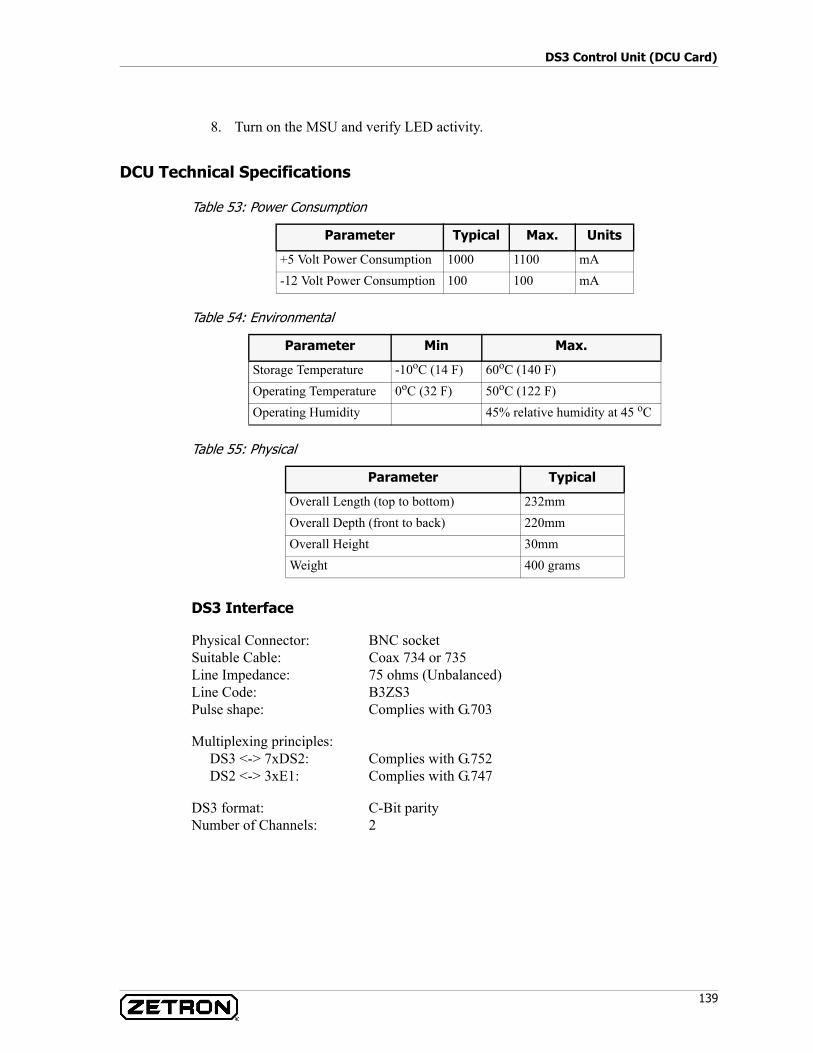
139
DS3 Control Unit (DCU Card)
8. Turn on the MSU and verify LED activity.
DCU Technical Specifications
Table 53: Power Consumption
Table 54: Environmental
Table 55: Physical
DS3 Interface
Physical Connector: BNC socketSuitable Cable: Coax 734 or 735Line Impedance: 75 ohms (Unbalanced)Line Code: B3ZS3Pulse shape: Complies with G.703
Multiplexing principles:DS3 <-> 7xDS2: Complies with G.752DS2 <-> 3xE1: Complies with G.747
DS3 format: C-Bit parityNumber of Channels: 2
Parameter Typical Max. Units
+5 Volt Power Consumption 1000 1100 mA-12 Volt Power Consumption 100 100 mA
Parameter Min Max.
Storage Temperature -10oC (14 F) 60oC (140 F)Operating Temperature 0oC (32 F) 50oC (122 F)Operating Humidity 45% relative humidity at 45 oC
Parameter Typical
Overall Length (top to bottom) 232mmOverall Depth (front to back) 220mmOverall Height 30mmWeight 400 grams
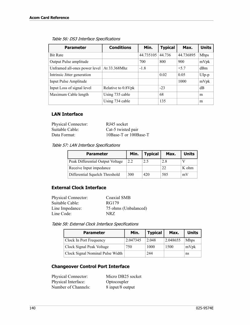
Acom Card Reference
140 025-9574E
Table 56: DS3 Interface Specifications
LAN Interface
Physical Connector: RJ45 socketSuitable Cable: Cat-5 twisted pairData Format: 10Base-T or 100Base-T
Table 57: LAN Interface Specifications
External Clock Interface
Physical Connector: Coaxial SMBSuitable Cable: RG179Line Impedance: 75 ohms (Unbalanced)Line Code: NRZ
Table 58: External Clock Interface Specifications
Changeover Control Port Interface
Physical Connector: Micro DB25 socketPhysical Interface: OptocouplerNumber of Channels: 8 input/8 output
Parameter Conditions Min. Typical Max. Units
Bit Rate 44.735105 44.736 44.736895 MbpsOutput Pulse amplitude 700 800 900 mVpkUnframed all-ones power level At 33.368Mhz -1.8 +5.7 dBmIntrinsic Jitter generation 0.02 0.05 UIp-pInput Pulse Amplitude 1000 mVpkInput Loss of signal level Relative to 0.8Vpk -23 dBMaximum Cable length Using 735 cable 68 m
Using 734 cable 135 m
Parameter Min. Typical Max. Units
Peak Differential Output Voltage 2.2 2.5 2.8 VReceive Input impedance 22 K ohmDifferential Squelch Threshold 300 420 585 mV
Parameter Min. Typical Max. Units
Clock In Port Frequency 2.047345 2.048 2.048655 MbpsClock Signal Peak Voltage 750 1000 1500 mVpkClock Signal Nominal Pulse Width 244 ns
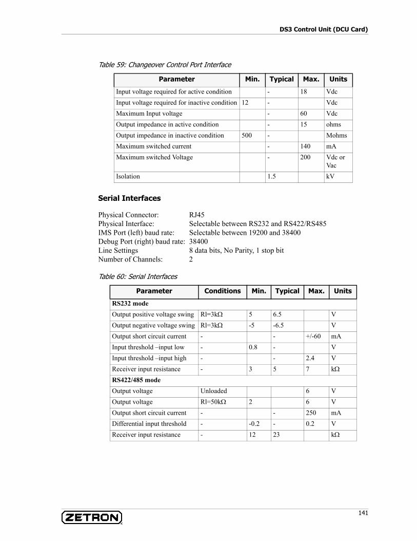
141
DS3 Control Unit (DCU Card)
Table 59: Changeover Control Port Interface
Serial Interfaces
Physical Connector: RJ45Physical Interface: Selectable between RS232 and RS422/RS485IMS Port (left) baud rate: Selectable between 19200 and 38400Debug Port (right) baud rate: 38400Line Settings 8 data bits, No Parity, 1 stop bitNumber of Channels: 2
Table 60: Serial Interfaces
Parameter Min. Typical Max. Units
Input voltage required for active condition - 18 VdcInput voltage required for inactive condition 12 - VdcMaximum Input voltage - 60 VdcOutput impedance in active condition - 15 ohmsOutput impedance in inactive condition 500 - MohmsMaximum switched current - 140 mAMaximum switched Voltage - 200 Vdc or
VacIsolation 1.5 kV
Parameter Conditions Min. Typical Max. Units
RS232 modeOutput positive voltage swing Rl=3kΩ 5 6.5 VOutput negative voltage swing Rl=3kΩ -5 -6.5 VOutput short circuit current - - +/-60 mAInput threshold –input low - 0.8 - VInput threshold –input high - - 2.4 VReceiver input resistance - 3 5 7 kΩ
RS422/485 modeOutput voltage Unloaded 6 VOutput voltage Rl=50kΩ 2 6 VOutput short circuit current - - 250 mADifferential input threshold - -0.2 - 0.2 VReceiver input resistance - 12 23 kΩ
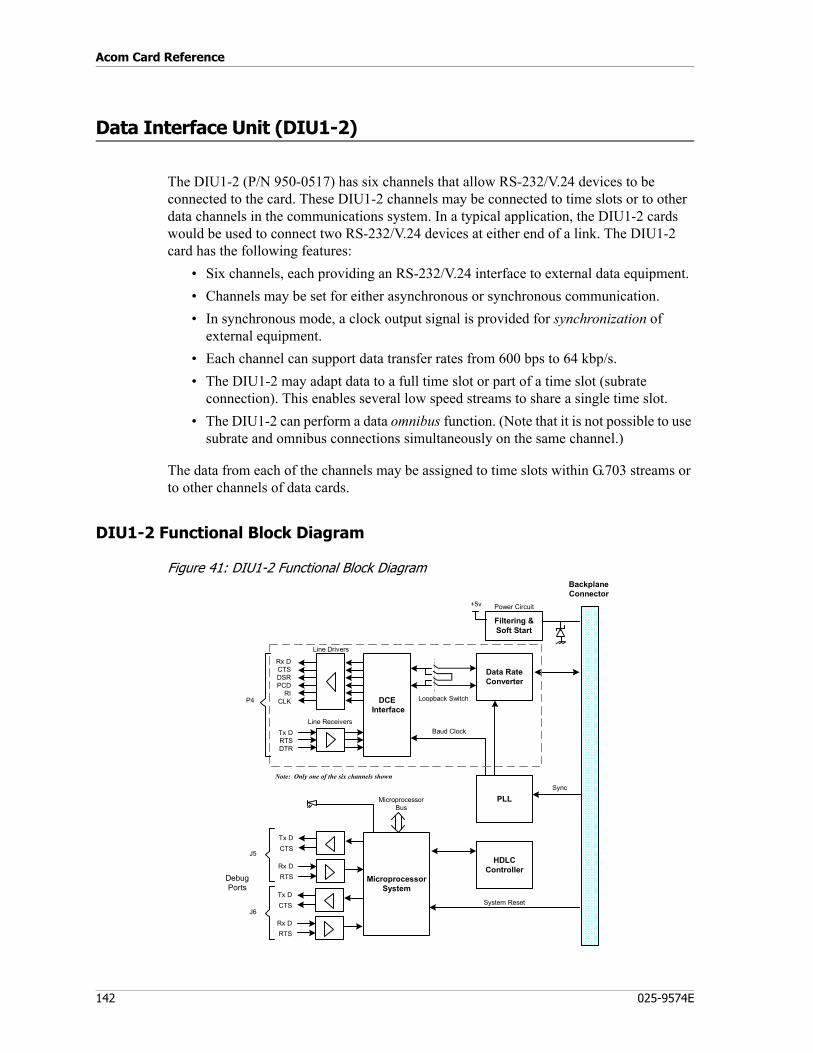
Acom Card Reference
142 025-9574E
Data Interface Unit (DIU1-2)
The DIU1-2 (P/N 950-0517) has six channels that allow RS-232/V.24 devices to be connected to the card. These DIU1-2 channels may be connected to time slots or to other data channels in the communications system. In a typical application, the DIU1-2 cards would be used to connect two RS-232/V.24 devices at either end of a link. The DIU1-2 card has the following features:
• Six channels, each providing an RS-232/V.24 interface to external data equipment.• Channels may be set for either asynchronous or synchronous communication.• In synchronous mode, a clock output signal is provided for synchronization of
external equipment.• Each channel can support data transfer rates from 600 bps to 64 kbp/s.• The DIU1-2 may adapt data to a full time slot or part of a time slot (subrate
connection). This enables several low speed streams to share a single time slot.• The DIU1-2 can perform a data omnibus function. (Note that it is not possible to use
subrate and omnibus connections simultaneously on the same channel.)
The data from each of the channels may be assigned to time slots within G.703 streams or to other channels of data cards.
DIU1-2 Functional Block Diagram
Figure 41: DIU1-2 Functional Block Diagram
Data RateConverter
MicroprocessorSystem
Rx DCTSDSRPCD
RICLK
Line Drivers
System Reset
BackplaneConnector
Note: Only one of the six channels shown
PLL
DCE Interface
Line Receivers
Power Circuit
Filtering &Soft Start
+5v
Loopback Switch
Tx DRTSDTR
Sync
HDLCController
Tx DCTS
Rx DRTS
Tx DCTS
Rx DRTS
Baud Clock
MicroprocessorBus
J6
J5
P4
DebugPorts
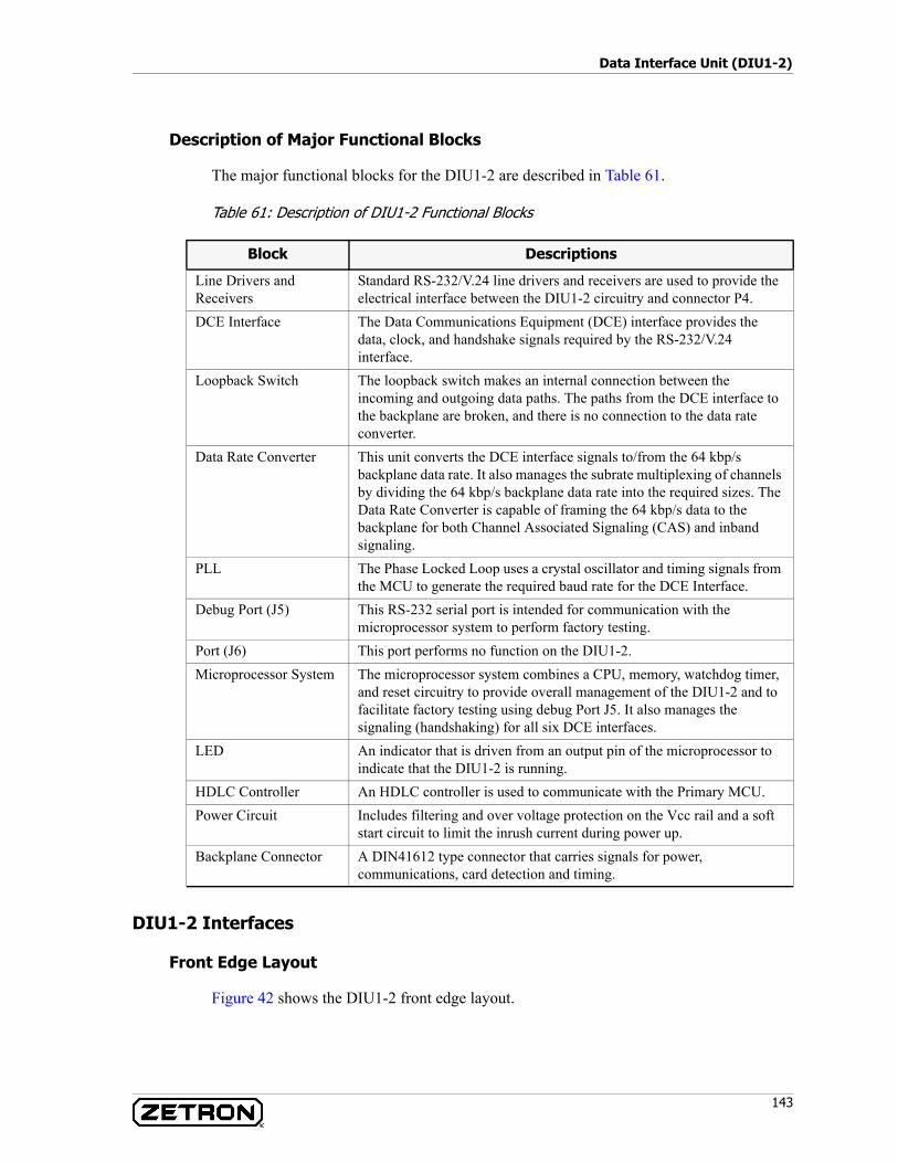
143
Data Interface Unit (DIU1-2)
Description of Major Functional Blocks
The major functional blocks for the DIU1-2 are described in Table 61.
Table 61: Description of DIU1-2 Functional Blocks
DIU1-2 Interfaces
Front Edge Layout
Figure 42 shows the DIU1-2 front edge layout.
Block Descriptions
Line Drivers and Receivers
Standard RS-232/V.24 line drivers and receivers are used to provide the electrical interface between the DIU1-2 circuitry and connector P4.
DCE Interface The Data Communications Equipment (DCE) interface provides the data, clock, and handshake signals required by the RS-232/V.24 interface.
Loopback Switch The loopback switch makes an internal connection between the incoming and outgoing data paths. The paths from the DCE interface to the backplane are broken, and there is no connection to the data rate converter.
Data Rate Converter This unit converts the DCE interface signals to/from the 64 kbp/s backplane data rate. It also manages the subrate multiplexing of channels by dividing the 64 kbp/s backplane data rate into the required sizes. The Data Rate Converter is capable of framing the 64 kbp/s data to the backplane for both Channel Associated Signaling (CAS) and inband signaling.
PLL The Phase Locked Loop uses a crystal oscillator and timing signals from the MCU to generate the required baud rate for the DCE Interface.
Debug Port (J5) This RS-232 serial port is intended for communication with the microprocessor system to perform factory testing.
Port (J6) This port performs no function on the DIU1-2. Microprocessor System The microprocessor system combines a CPU, memory, watchdog timer,
and reset circuitry to provide overall management of the DIU1-2 and to facilitate factory testing using debug Port J5. It also manages the signaling (handshaking) for all six DCE interfaces.
LED An indicator that is driven from an output pin of the microprocessor to indicate that the DIU1-2 is running.
HDLC Controller An HDLC controller is used to communicate with the Primary MCU.Power Circuit Includes filtering and over voltage protection on the Vcc rail and a soft
start circuit to limit the inrush current during power up.Backplane Connector A DIN41612 type connector that carries signals for power,
communications, card detection and timing.
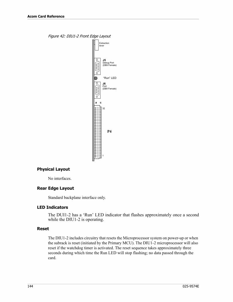
Acom Card Reference
144 025-9574E
Figure 42: DIU1-2 Front Edge Layout
Physical Layout
No interfaces.
Rear Edge Layout
Standard backplane interface only.
LED Indicators
The DUI1-2 has a ‘Run’ LED indicator that flashes approximately once a secondwhile the DIU1-2 is operating.
Reset
The DIU1-2 includes circuitry that resets the Microprocessor system on power-up or when the subrack is reset (initiated by the Primary MCU). The DIU1-2 microprocessor will also reset if the watchdog timer is activated. The reset sequence takes approximately three seconds during which time the Run LED will stop flashing; no data passed through the card.
a c
32
1
Extractionlever
J6Port(DB9 Female)
“Run” LED
J5Debug Port(DB9 Female)
P4
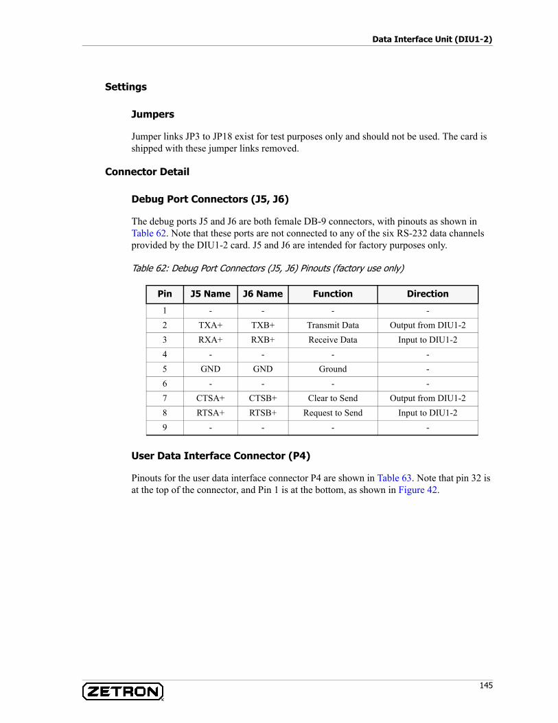
145
Data Interface Unit (DIU1-2)
Settings
Jumpers
Jumper links JP3 to JP18 exist for test purposes only and should not be used. The card is shipped with these jumper links removed.
Connector Detail
Debug Port Connectors (J5, J6)
The debug ports J5 and J6 are both female DB-9 connectors, with pinouts as shown in Table 62. Note that these ports are not connected to any of the six RS-232 data channels provided by the DIU1-2 card. J5 and J6 are intended for factory purposes only.
Table 62: Debug Port Connectors (J5, J6) Pinouts (factory use only)
User Data Interface Connector (P4)
Pinouts for the user data interface connector P4 are shown in Table 63. Note that pin 32 is at the top of the connector, and Pin 1 is at the bottom, as shown in Figure 42.
Pin J5 Name J6 Name Function Direction
1 - - - -2 TXA+ TXB+ Transmit Data Output from DIU1-23 RXA+ RXB+ Receive Data Input to DIU1-24 - - - -5 GND GND Ground -6 - - - -7 CTSA+ CTSB+ Clear to Send Output from DIU1-28 RTSA+ RTSB+ Request to Send Input to DIU1-29 - - - -
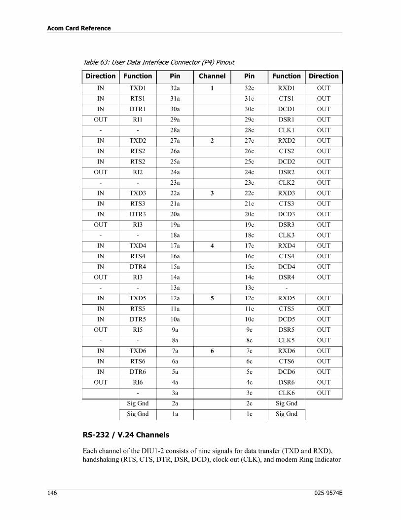
Acom Card Reference
146 025-9574E
Table 63: User Data Interface Connector (P4) Pinout
RS-232 / V.24 Channels
Each channel of the DIU1-2 consists of nine signals for data transfer (TXD and RXD), handshaking (RTS, CTS, DTR, DSR, DCD), clock out (CLK), and modem Ring Indicator
Direction Function Pin Channel Pin Function Direction
IN TXD1 32a 1 32c RXD1 OUTIN RTS1 31a 31c CTS1 OUTIN DTR1 30a 30c DCD1 OUT
OUT RI1 29a 29c DSR1 OUT- - 28a 28c CLK1 OUT
IN TXD2 27a 2 27c RXD2 OUTIN RTS2 26a 26c CTS2 OUTIN RTS2 25a 25c DCD2 OUT
OUT RI2 24a 24c DSR2 OUT- - 23a 23c CLK2 OUT
IN TXD3 22a 3 22c RXD3 OUTIN RTS3 21a 21c CTS3 OUTIN DTR3 20a 20c DCD3 OUT
OUT RI3 19a 19c DSR3 OUT- - 18a 18c CLK3 OUT
IN TXD4 17a 4 17c RXD4 OUTIN RTS4 16a 16c CTS4 OUTIN DTR4 15a 15c DCD4 OUT
OUT RI3 14a 14c DSR4 OUT- - 13a 13c -
IN TXD5 12a 5 12c RXD5 OUTIN RTS5 11a 11c CTS5 OUTIN DTR5 10a 10c DCD5 OUT
OUT RI5 9a 9c DSR5 OUT- - 8a 8c CLK5 OUT
IN TXD6 7a 6 7c RXD6 OUTIN RTS6 6a 6c CTS6 OUTIN DTR6 5a 5c DCD6 OUT
OUT RI6 4a 4c DSR6 OUT- 3a 3c CLK6 OUT
Sig Gnd 2a 2c Sig GndSig Gnd 1a 1c Sig Gnd
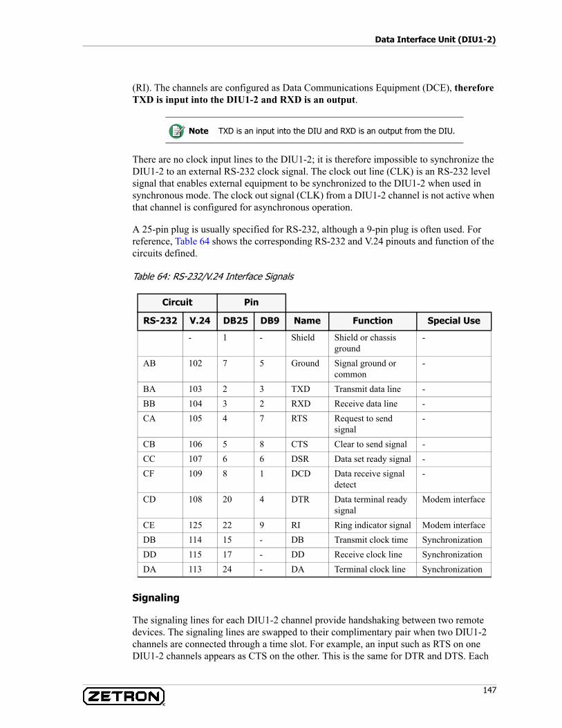
147
Data Interface Unit (DIU1-2)
(RI). The channels are configured as Data Communications Equipment (DCE), therefore TXD is input into the DIU1-2 and RXD is an output.
There are no clock input lines to the DIU1-2; it is therefore impossible to synchronize the DIU1-2 to an external RS-232 clock signal. The clock out line (CLK) is an RS-232 level signal that enables external equipment to be synchronized to the DIU1-2 when used in synchronous mode. The clock out signal (CLK) from a DIU1-2 channel is not active when that channel is configured for asynchronous operation.
A 25-pin plug is usually specified for RS-232, although a 9-pin plug is often used. For reference, Table 64 shows the corresponding RS-232 and V.24 pinouts and function of the circuits defined.
Table 64: RS-232/V.24 Interface Signals
Signaling
The signaling lines for each DIU1-2 channel provide handshaking between two remote devices. The signaling lines are swapped to their complimentary pair when two DIU1-2 channels are connected through a time slot. For example, an input such as RTS on one DIU1-2 channels appears as CTS on the other. This is the same for DTR and DTS. Each
Note TXD is an input into the DIU and RXD is an output from the DIU.
Circuit Pin
RS-232 V.24 DB25 DB9 Name Function Special Use
- 1 - Shield Shield or chassis ground
-
AB 102 7 5 Ground Signal ground or common
-
BA 103 2 3 TXD Transmit data line -BB 104 3 2 RXD Receive data line -CA 105 4 7 RTS Request to send
signal-
CB 106 5 8 CTS Clear to send signal -CC 107 6 6 DSR Data set ready signal -CF 109 8 1 DCD Data receive signal
detect-
CD 108 20 4 DTR Data terminal ready signal
Modem interface
CE 125 22 9 RI Ring indicator signal Modem interfaceDB 114 15 - DB Transmit clock time SynchronizationDD 115 17 - DD Receive clock line SynchronizationDA 113 24 - DA Terminal clock line Synchronization
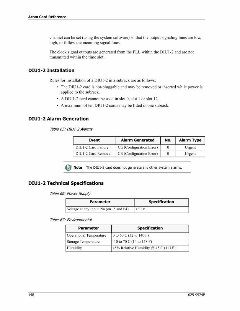
Acom Card Reference
148 025-9574E
channel can be set (using the system software) so that the output signaling lines are low, high, or follow the incoming signal lines.
The clock signal outputs are generated from the PLL within the DIU1-2 and are not transmitted within the time slot.
DIU1-2 Installation
Rules for installation of a DIU1-2 in a subrack are as follows:• The DIU1-2 card is hot-pluggable and may be removed or inserted while power is
applied to the subrack.• A DIU1-2 card cannot be used in slot 0, slot 1 or slot 12.• A maximum of ten DIU1-2 cards may be fitted in one subrack.
DIU1-2 Alarm Generation
Table 65: DIU1-2 Alarms
DIU1-2 Technical Specifications
Table 66: Power Supply
Table 67: Environmental
Event Alarm Generated No. Alarm Type
DIU1-2 Card Failure CE (Configuration Error) 0 UrgentDIU1-2 Card Removal CE (Configuration Error) 0 Urgent
Note The DIU1-2 card does not generate any other system alarms.
Parameter Specification
Voltage at any Input Pin (on J5 and P4) ±30 V
Parameter Specification
Operational Temperature 0 to 60 C (32 to 140 F)Storage Temperature -10 to 70 C (14 to 158 F)Humidity 45% Relative Humidity @ 45 C (113 F)
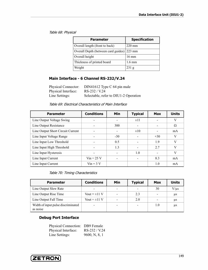
149
Data Interface Unit (DIU1-2)
Table 68: Physical
Main Interface - 6 Channel RS-232/V.24
Physical Connector: DIN41612 Type C 64 pin malePhysical Interface: RS-232 / V.24Line Settings: Selectable, refer to DIU1-2 Operation
Table 69: Electrical Characteristics of Main Interface
Table 70: Timing Characteristics
Debug Port Interface
Physical Connection: DB9 FemalePhysical Interface: RS-232 / V.24Line Settings: 9600, N, 8, 1
Parameter Specification
Overall length (front to back) 220 mmOverall Depth (between card guides) 223 mmOverall height 16 mmThickness of printed board 1.6 mmWeight 231 g
Parameter Conditions Min Typical Max Units
Line Output Voltage Swing - - ±11 - VLine Output Resistance - 300 - - Ω
Line Output Short Circuit Current - - ±10 - mALine Input Voltage Range - -30 - +30 VLine Input Low Threshold - 0.5 - 1.9 VLine Input High Threshold - 1.3 - 2.7 VLine Input Hysteresis - - 1.0 - VLine Input Current Vin = 25 V - - 8.3 mALine Input Current Vin = 3 V 1.0 mA
Parameter Conditions Min Typical Max Units
Line Output Slew Rate - - - 30 V/µsLine Output Rise Time Vout = ±11 V - 2.3 - µsLine Output Fall Time Vout = ±11 V - 2.0 - µsWidth of input pulse discriminated as noise
- - - 1.0 µs
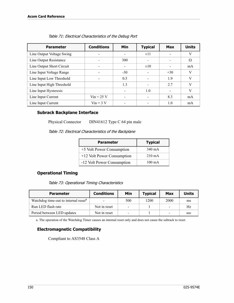
Acom Card Reference
150 025-9574E
Table 71: Electrical Characteristics of the Debug Port
Subrack Backplane Interface
Physical Connector DIN41612 Type C 64 pin male
Table 72: Electrical Characteristics of the Backplane
Operational Timing
Table 73: Operational Timing Characteristics
Electromagnetic Compatibility
Compliant to AS3548 Class A
Parameter Conditions Min Typical Max Units
Line Output Voltage Swing - - ±11 - VLine Output Resistance - 300 - - Ω
Line Output Short Circuit - - ±10 - mALine Input Voltage Range - -30 - +30 VLine Input Low Threshold - 0.5 - 1.9 VLine Input High Threshold 1.3 - 2.7 VLine Input Hysteresis - 1.0 - VLine Input Current Vin = 25 V - - 8.3 mALine Input Current Vin = 3 V - - 1.0 mA
Parameter Typical
+5 Volt Power Consumption 340 mA
+12 Volt Power Consumption 210 mA
-12 Volt Power Consumption 100 mA
Parameter Conditions Min Typical Max Units
Watchdog time-out to internal reseta - 500 1200 2000 msRun LED flash rate Not in reset - 1 - HzPeriod between LED updates Not in reset - 1 - sec
a. The operation of the Watchdog Timer causes an internal reset only and does not cause the subrack to reset.
151
Data Interface Unit (DIU1-4)
Data Interface Unit (DIU1-4)
P/N 950-0516
The DIU1-4 has six channels that allow RS-422/V.11 devices to be connected to time slots or to other line cards. The DIU1-4 is typically used to connect two RS-422/v.11 devices to either end of a communications network.
The DIU1-4 card has the following features:• Six independent channels, each providing an RS-422/V.11 interface to external data
equipment.• Channels may be individually set up as either asynchronous or synchronous.• In the synchronous mode, clock output signals are provided for synchronization of
external equipment.• Each channel can support data transfer rates from 600 bp/s to 64 kbp/s.• The DIU1-4 may adapt data to a full time slot or part of a time slot (subrate
connection). This enables several low speed streams to share a single time slot.• The DIU1-4 can perform a data omnibus function. (Note that it is not possible to
use subrate and omnibus connections simultaneously on the same channel.)• The data from each of the channels may be assigned to time slots within G.703
streams or to channels of other line cards.
DIU1-4 Block Diagram
Figure 43 shows the functional block diagram for an DIU1-4.
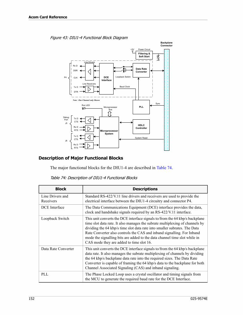
Acom Card Reference
152 025-9574E
Figure 43: DIU1-4 Functional Block Diagram
Description of Major Functional Blocks
The major functional blocks for the DIU1-4 are described in Table 74.
Table 74: Description of DIU1-4 Functional Blocks
Data RateConverter
MicroprocessorSystem
System Reset
BackplaneConnector
Note: One Channel only Shown
PLL
DCE Interface
Power Circuit
Filtering &Soft Start
+5V
Loopback Switch
Sync
HDLCController
Tx DCTS
Rx DRTS
Baud Clock
MicroprocessorBus
J6
J5
Rx D
DSR
CLK
Line Drivers
Line ReceiversTx D
DTR
P4
Run LED
DebugPort
Tx DCTS
Rx DRTS
Block Descriptions
Line Drivers and Receivers
Standard RS-422/V.11 line drivers and receivers are used to provide the electrical interface between the DIU1-4 circuitry and connector P4.
DCE Interface The Data Communications Equipment (DCE) interface provides the data, clock and handshake signals required by an RS-422/V.11 interface.
Loopback Switch This unit converts the DCE interface signals to/from the 64 kbp/s backplane time slot data rate. It also manages the subrate multiplexing of channels by dividing the 64 kbp/s time slot data rate into smaller subrates. The Data Rate Converter also controls the CAS and inband signalling. For Inband mode the signalling bits are added to the data channel time slot while in CAS mode they are added to time slot 16.
Data Rate Converter This unit converts the DCE interface signals to/from the 64 kbp/s backplane data rate. It also manages the subrate multiplexing of channels by dividing the 64 kbp/s backplane data rate into the required sizes. The Data Rate Converter is capable of framing the 64 kbp/s data to the backplane for both Channel Associated Signaling (CAS) and inband signaling.
PLL The Phase Locked Loop uses a crystal oscillator and timing signals from the MCU to generate the required baud rate for the DCE Interface.
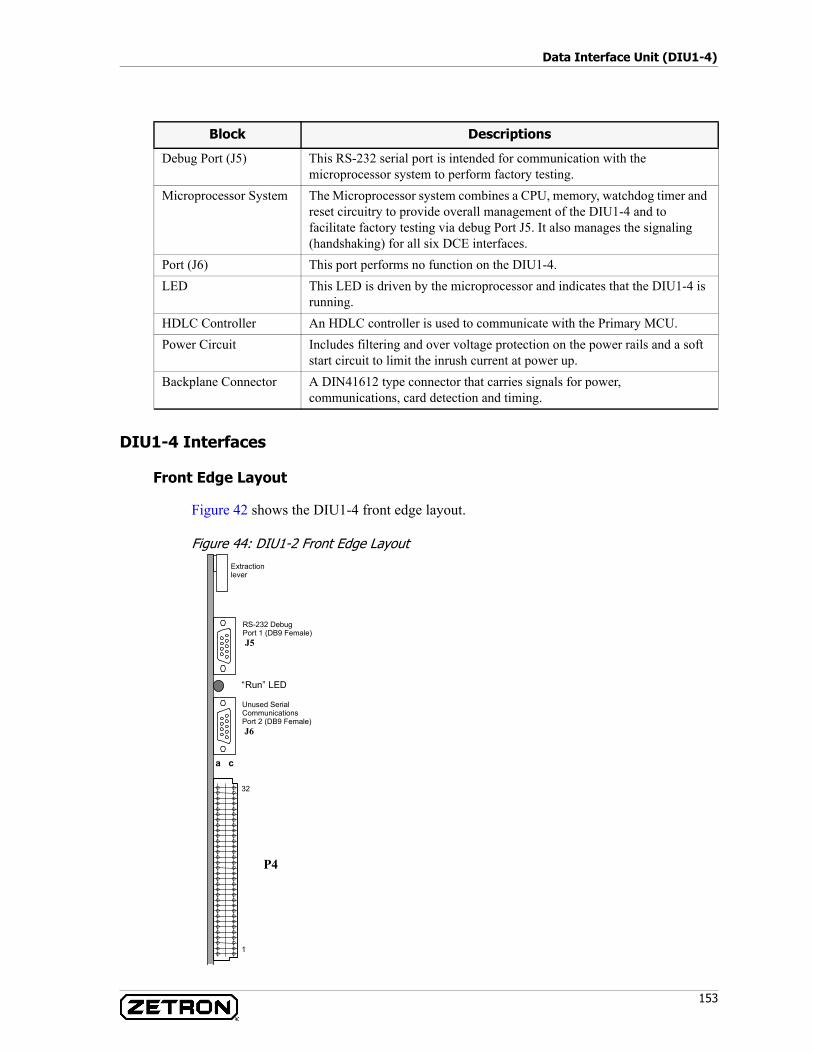
153
Data Interface Unit (DIU1-4)
DIU1-4 Interfaces
Front Edge Layout
Figure 42 shows the DIU1-4 front edge layout.
Figure 44: DIU1-2 Front Edge Layout
Debug Port (J5) This RS-232 serial port is intended for communication with the microprocessor system to perform factory testing.
Microprocessor System The Microprocessor system combines a CPU, memory, watchdog timer and reset circuitry to provide overall management of the DIU1-4 and to facilitate factory testing via debug Port J5. It also manages the signaling (handshaking) for all six DCE interfaces.
Port (J6) This port performs no function on the DIU1-4. LED This LED is driven by the microprocessor and indicates that the DIU1-4 is
running.HDLC Controller An HDLC controller is used to communicate with the Primary MCU.Power Circuit Includes filtering and over voltage protection on the power rails and a soft
start circuit to limit the inrush current at power up.Backplane Connector A DIN41612 type connector that carries signals for power,
communications, card detection and timing.
Block Descriptions
a c
32
1
Extractionlever
Unused SerialCommunicationsPort 2 (DB9 Female) J6
“Run” LED
RS-232 DebugPort 1 (DB9 Female) J5
P4
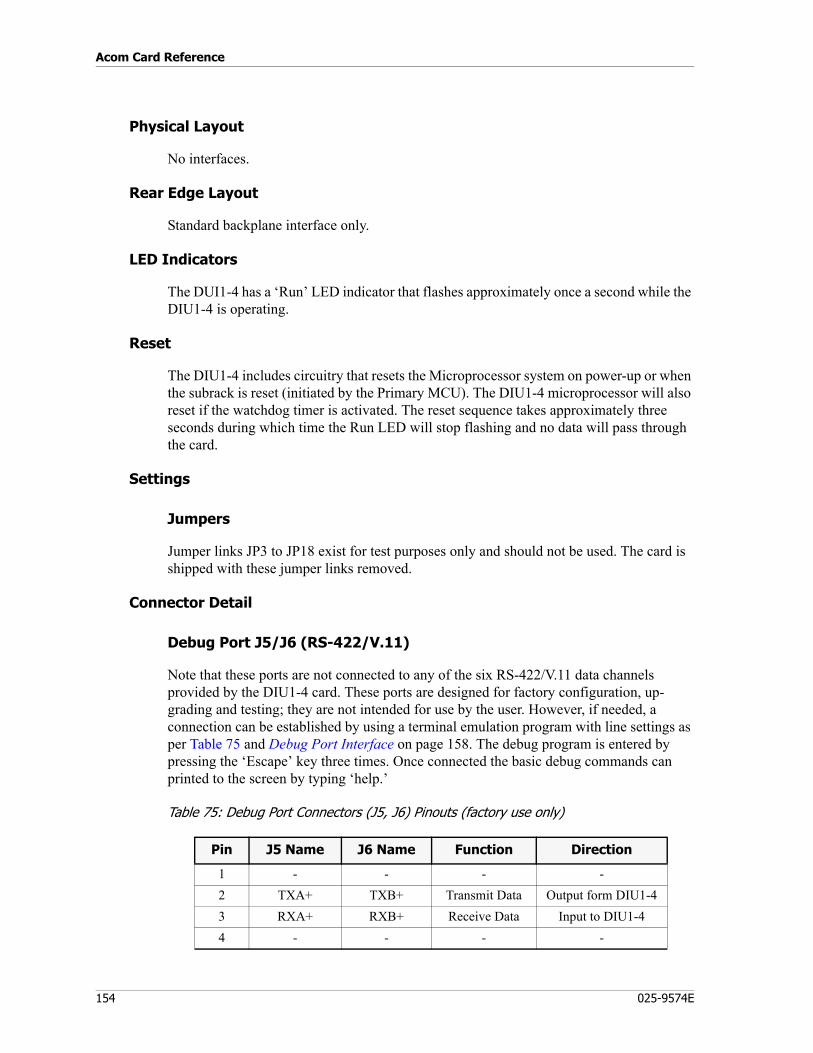
Acom Card Reference
154 025-9574E
Physical Layout
No interfaces.
Rear Edge Layout
Standard backplane interface only.
LED Indicators
The DUI1-4 has a ‘Run’ LED indicator that flashes approximately once a second while the DIU1-4 is operating.
Reset
The DIU1-4 includes circuitry that resets the Microprocessor system on power-up or when the subrack is reset (initiated by the Primary MCU). The DIU1-4 microprocessor will also reset if the watchdog timer is activated. The reset sequence takes approximately three seconds during which time the Run LED will stop flashing and no data will pass through the card.
Settings
Jumpers
Jumper links JP3 to JP18 exist for test purposes only and should not be used. The card is shipped with these jumper links removed.
Connector Detail
Debug Port J5/J6 (RS-422/V.11)
Note that these ports are not connected to any of the six RS-422/V.11 data channels provided by the DIU1-4 card. These ports are designed for factory configuration, up-grading and testing; they are not intended for use by the user. However, if needed, a connection can be established by using a terminal emulation program with line settings as per Table 75 and Debug Port Interface on page 158. The debug program is entered by pressing the ‘Escape’ key three times. Once connected the basic debug commands can printed to the screen by typing ‘help.’
Table 75: Debug Port Connectors (J5, J6) Pinouts (factory use only)
Pin J5 Name J6 Name Function Direction
1 - - - -2 TXA+ TXB+ Transmit Data Output form DIU1-43 RXA+ RXB+ Receive Data Input to DIU1-44 - - - -
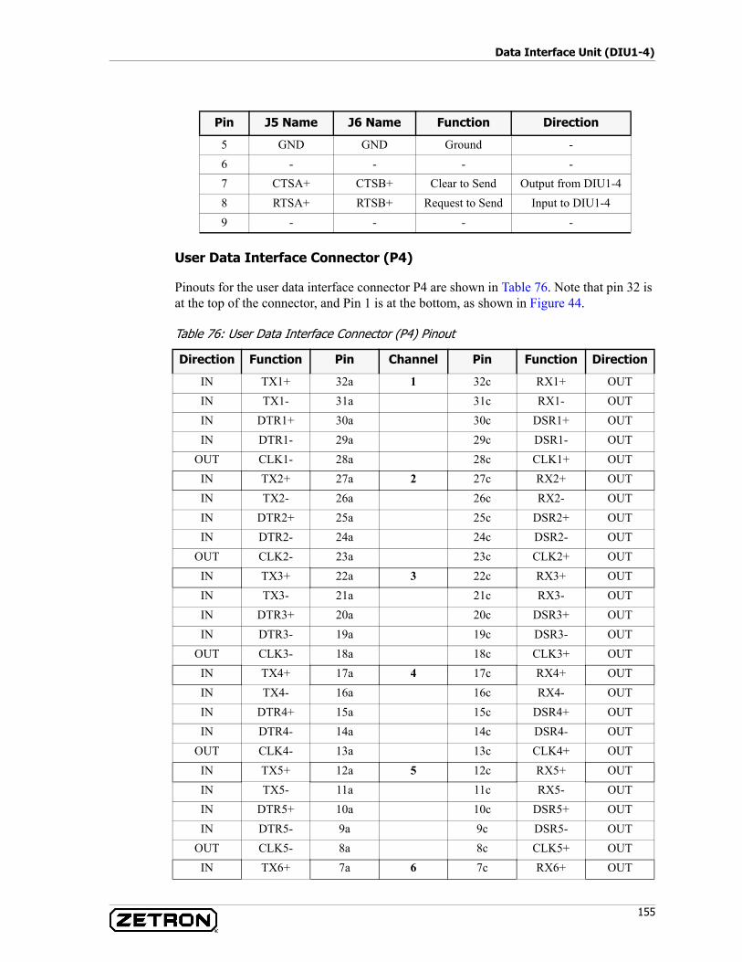
155
Data Interface Unit (DIU1-4)
User Data Interface Connector (P4)
Pinouts for the user data interface connector P4 are shown in Table 76. Note that pin 32 is at the top of the connector, and Pin 1 is at the bottom, as shown in Figure 44.
Table 76: User Data Interface Connector (P4) Pinout
5 GND GND Ground -6 - - - -7 CTSA+ CTSB+ Clear to Send Output from DIU1-48 RTSA+ RTSB+ Request to Send Input to DIU1-49 - - - -
Direction Function Pin Channel Pin Function Direction
IN TX1+ 32a 1 32c RX1+ OUTIN TX1- 31a 31c RX1- OUTIN DTR1+ 30a 30c DSR1+ OUTIN DTR1- 29a 29c DSR1- OUT
OUT CLK1- 28a 28c CLK1+ OUTIN TX2+ 27a 2 27c RX2+ OUTIN TX2- 26a 26c RX2- OUTIN DTR2+ 25a 25c DSR2+ OUTIN DTR2- 24a 24c DSR2- OUT
OUT CLK2- 23a 23c CLK2+ OUTIN TX3+ 22a 3 22c RX3+ OUTIN TX3- 21a 21c RX3- OUTIN DTR3+ 20a 20c DSR3+ OUTIN DTR3- 19a 19c DSR3- OUT
OUT CLK3- 18a 18c CLK3+ OUTIN TX4+ 17a 4 17c RX4+ OUTIN TX4- 16a 16c RX4- OUTIN DTR4+ 15a 15c DSR4+ OUTIN DTR4- 14a 14c DSR4- OUT
OUT CLK4- 13a 13c CLK4+ OUTIN TX5+ 12a 5 12c RX5+ OUTIN TX5- 11a 11c RX5- OUTIN DTR5+ 10a 10c DSR5+ OUTIN DTR5- 9a 9c DSR5- OUT
OUT CLK5- 8a 8c CLK5+ OUTIN TX6+ 7a 6 7c RX6+ OUT
Pin J5 Name J6 Name Function Direction
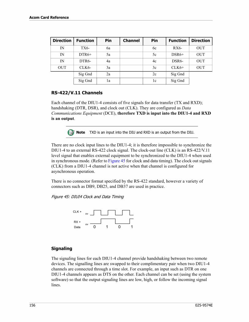
Acom Card Reference
156 025-9574E
RS-422/V.11 Channels
Each channel of the DIU1-4 consists of five signals for data transfer (TX and RXD); handshaking (DTR, DSR), and clock out (CLK). They are configured as Data Communications Equipment (DCE), therefore TXD is input into the DIU1-4 and RXD is an output.
There are no clock input lines to the DIU1-4; it is therefore impossible to synchronize the DIU1-4 to an external RS-422 clock signal. The clock-out line (CLK) is an RS-422/V.11 level signal that enables external equipment to be synchronized to the DIU1-4 when used in synchronous mode. (Refer to Figure 45 for clock and data timing). The clock out signals (CLK) from a DIU1-4 channel is not active when that channel is configured for asynchronous operation.
There is no connector format specified by the RS-422 standard, however a variety of connectors such as DB9, DB25, and DB37 are used in practice.
Figure 45: DIUI4 Clock and Data Timing
Signaling
The signaling lines for each DIU1-4 channel provide handshaking between two remote devices. The signalling lines are swapped to their complimentary pair when two DIU1-4 channels are connected through a time slot. For example, an input such as DTR on one DIU1-4 channels appears as DTS on the other. Each channel can be set (using the system software) so that the output signaling lines are low, high, or follow the incoming signal lines.
IN TX6- 6a 6c RX6- OUTIN DTR6+ 5a 5c DSR6+ OUTIN DTR6- 4a 4c DSR6- OUT
OUT CLK6- 3a 3c CLK6+ OUTSig Gnd 2a 2c Sig GndSig Gnd 1a 1c Sig Gnd
Note TXD is an input into the DIU and RXD is an output from the DIU.
Direction Function Pin Channel Pin Function Direction
ov
ov0 1 0 1
CLK +
RX +
Data
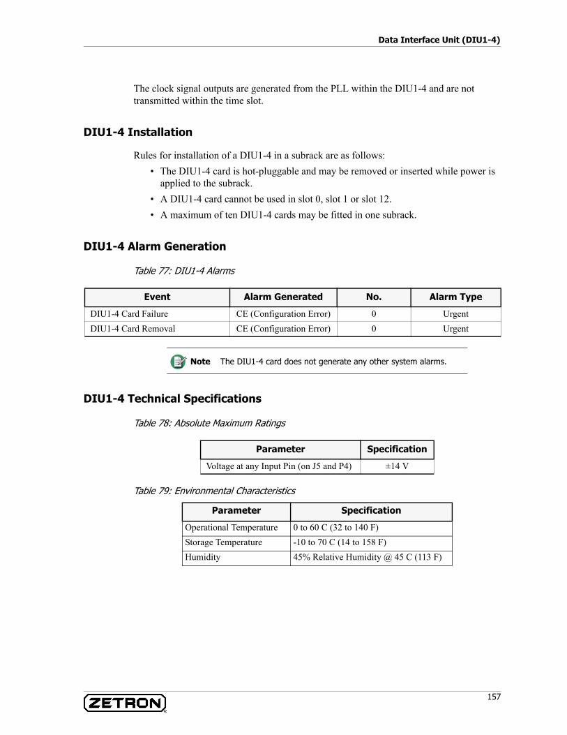
157
Data Interface Unit (DIU1-4)
The clock signal outputs are generated from the PLL within the DIU1-4 and are not transmitted within the time slot.
DIU1-4 Installation
Rules for installation of a DIU1-4 in a subrack are as follows:• The DIU1-4 card is hot-pluggable and may be removed or inserted while power is
applied to the subrack. • A DIU1-4 card cannot be used in slot 0, slot 1 or slot 12. • A maximum of ten DIU1-4 cards may be fitted in one subrack.
DIU1-4 Alarm Generation
Table 77: DIU1-4 Alarms
DIU1-4 Technical Specifications
Table 78: Absolute Maximum Ratings
Table 79: Environmental Characteristics
Event Alarm Generated No. Alarm Type
DIU1-4 Card Failure CE (Configuration Error) 0 UrgentDIU1-4 Card Removal CE (Configuration Error) 0 Urgent
Note The DIU1-4 card does not generate any other system alarms.
Parameter Specification
Voltage at any Input Pin (on J5 and P4) ±14 V
Parameter Specification
Operational Temperature 0 to 60 C (32 to 140 F)Storage Temperature -10 to 70 C (14 to 158 F)Humidity 45% Relative Humidity @ 45 C (113 F)
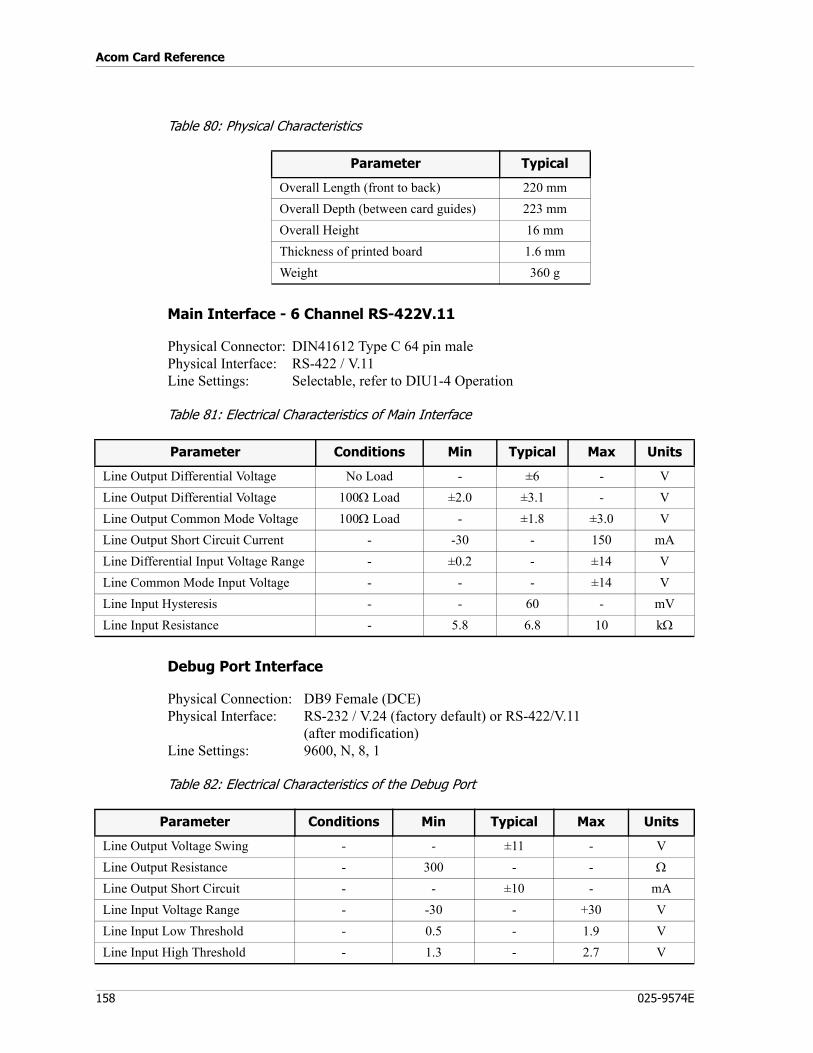
Acom Card Reference
158 025-9574E
Table 80: Physical Characteristics
Main Interface - 6 Channel RS-422V.11
Physical Connector: DIN41612 Type C 64 pin malePhysical Interface: RS-422 / V.11Line Settings: Selectable, refer to DIU1-4 Operation
Table 81: Electrical Characteristics of Main Interface
Debug Port Interface
Physical Connection: DB9 Female (DCE)Physical Interface: RS-232 / V.24 (factory default) or RS-422/V.11
(after modification)Line Settings: 9600, N, 8, 1
Table 82: Electrical Characteristics of the Debug Port
Parameter Typical
Overall Length (front to back) 220 mmOverall Depth (between card guides) 223 mmOverall Height 16 mmThickness of printed board 1.6 mmWeight 360 g
Parameter Conditions Min Typical Max Units
Line Output Differential Voltage No Load - ±6 - VLine Output Differential Voltage 100Ω Load ±2.0 ±3.1 - VLine Output Common Mode Voltage 100Ω Load - ±1.8 ±3.0 VLine Output Short Circuit Current - -30 - 150 mALine Differential Input Voltage Range - ±0.2 - ±14 VLine Common Mode Input Voltage - - - ±14 VLine Input Hysteresis - - 60 - mVLine Input Resistance - 5.8 6.8 10 kΩ
Parameter Conditions Min Typical Max Units
Line Output Voltage Swing - - ±11 - VLine Output Resistance - 300 - - Ω
Line Output Short Circuit - - ±10 - mALine Input Voltage Range - -30 - +30 VLine Input Low Threshold - 0.5 - 1.9 VLine Input High Threshold - 1.3 - 2.7 V
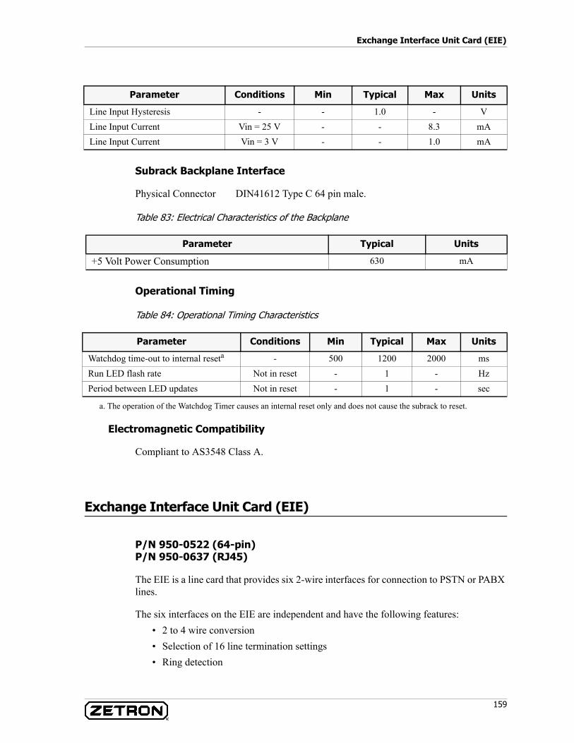
159
Exchange Interface Unit Card (EIE)
Subrack Backplane Interface
Physical Connector DIN41612 Type C 64 pin male.
Table 83: Electrical Characteristics of the Backplane
Operational Timing
Table 84: Operational Timing Characteristics
Electromagnetic Compatibility
Compliant to AS3548 Class A.
Exchange Interface Unit Card (EIE)
P/N 950-0522 (64-pin)P/N 950-0637 (RJ45)
The EIE is a line card that provides six 2-wire interfaces for connection to PSTN or PABX lines.
The six interfaces on the EIE are independent and have the following features:• 2 to 4 wire conversion• Selection of 16 line termination settings• Ring detection
Line Input Hysteresis - - 1.0 - VLine Input Current Vin = 25 V - - 8.3 mALine Input Current Vin = 3 V - - 1.0 mA
Parameter Conditions Min Typical Max Units
Parameter Typical Units
+5 Volt Power Consumption 630 mA
Parameter Conditions Min Typical Max Units
Watchdog time-out to internal reseta - 500 1200 2000 msRun LED flash rate Not in reset - 1 - HzPeriod between LED updates Not in reset - 1 - sec
a. The operation of the Watchdog Timer causes an internal reset only and does not cause the subrack to reset.
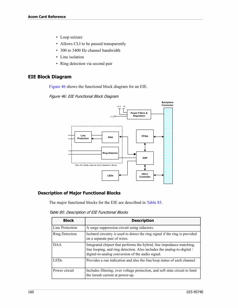
Acom Card Reference
160 025-9574E
• Loop seizure• Allows CLI to be passed transparently• 300 to 3400 Hz channel bandwidth• Line isolation• Ring detection via second pair
EIE Block Diagram
Figure 46 shows the functional block diagram for an EIE.
Figure 46: EIE Functional Block Diagram
Description of Major Functional Blocks
The major functional blocks for the EIE are described in Table 85.
Table 85: Description of EIE Functional Blocks
FPGA
LEDs HDLCController
BackplaneConnector
LineProtection
+1.5
Note: For clarity, only one of six channels is shown.
+3.3 +5
Power Filters &Regulation
DSP
Ring Detector
DAA
Block Description
Line Protection A surge suppression circuit using sidactors.Ring Detection Isolated circuitry is used to detect the ring signal if the ring is provided
on a separate pair of wires.DAA Integrated chipset that performs the hybrid, line impedance matching,
line looping, and ring detection. Also includes the analog-to-digital / digital-to-analog conversion of the audio signal.
LEDs Provides a run indication and also the line/loop status of each channel.
Power circuit Includes filtering, over voltage protection, and soft state circuit to limit the inrush current at power-up.
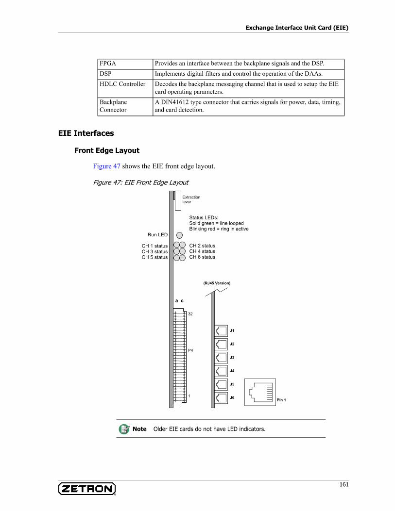
161
Exchange Interface Unit Card (EIE)
EIE Interfaces
Front Edge Layout
Figure 47 shows the EIE front edge layout.
Figure 47: EIE Front Edge Layout
FPGA Provides an interface between the backplane signals and the DSP.DSP Implements digital filters and control the operation of the DAAs.HDLC Controller Decodes the backplane messaging channel that is used to setup the EIE
card operating parameters.Backplane Connector
A DIN41612 type connector that carries signals for power, data, timing, and card detection.
Note Older EIE cards do not have LED indicators.
a c
32
P4
1
Extractionlever
Status LEDs:Solid green = line loopedBlinking red = ring in active
CH 2 statusCH 4 statusCH 6 status
Run LED
CH 1 statusCH 3 statusCH 5 status
J1
J3
J6
J2
J4
J5
(RJ45 Version)
Pin 1
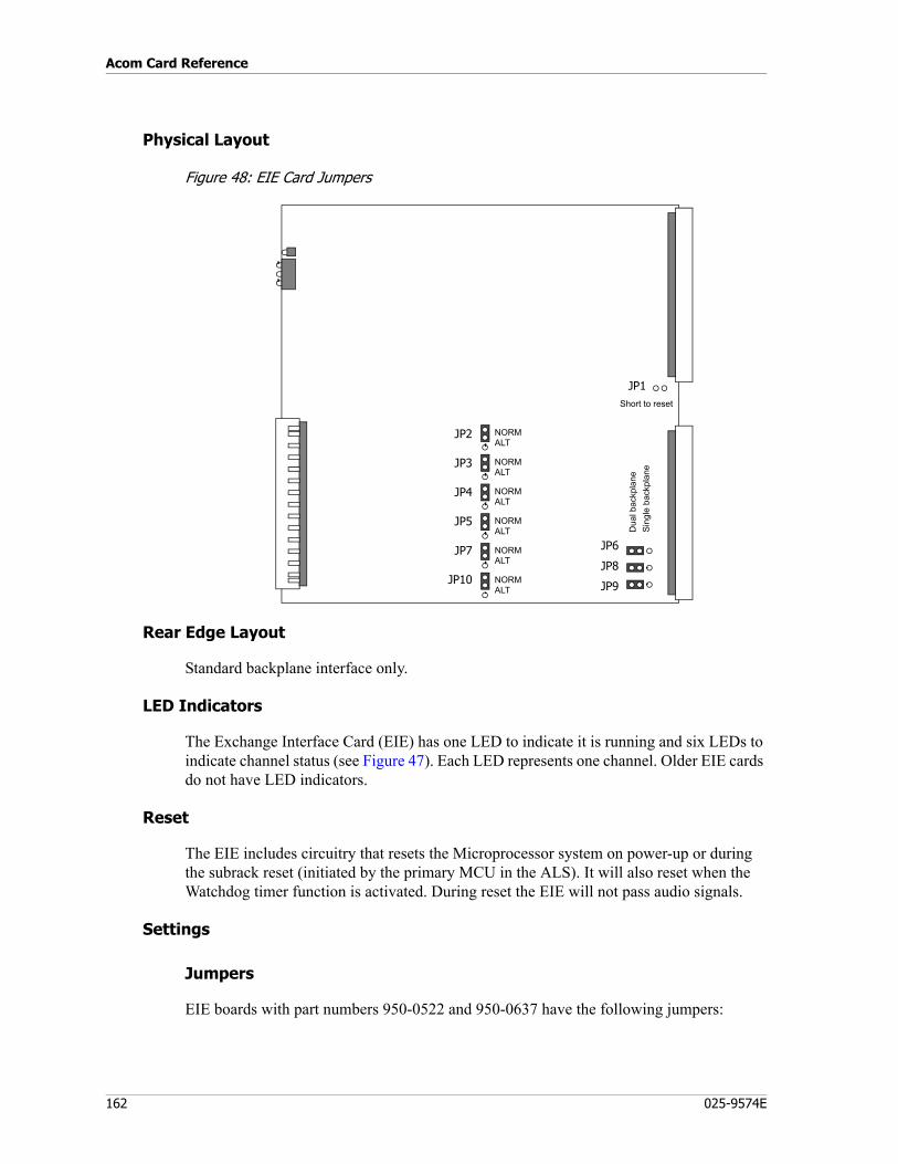
Acom Card Reference
162 025-9574E
Physical Layout
Figure 48: EIE Card Jumpers
Rear Edge Layout
Standard backplane interface only.
LED Indicators
The Exchange Interface Card (EIE) has one LED to indicate it is running and six LEDs to indicate channel status (see Figure 47). Each LED represents one channel. Older EIE cards do not have LED indicators.
Reset
The EIE includes circuitry that resets the Microprocessor system on power-up or during the subrack reset (initiated by the primary MCU in the ALS). It will also reset when the Watchdog timer function is activated. During reset the EIE will not pass audio signals.
Settings
Jumpers
EIE boards with part numbers 950-0522 and 950-0637 have the following jumpers:
JP2
JP3
JP4
JP5
JP7
JP10
JP1
NORMALT
NORMALT
NORMALT
NORMALT
NORMALT
NORMALT
JP6
JP8
JP9
Short to reset
Dua
l bac
kpla
neSi
ngle
bac
kpla
ne
163
Exchange Interface Unit Card (EIE)
JP1: Located below connector P1, this jumper is provided to allow resetting of the card. These pins are supplied with no jumper fitted. Momentarily shorting the pins of JP1 will RESET the card (for test purposes only).
JP6, JP8, and JP9: Located near the bottom right-hand corner of the PCB, these are used where the EIE card is to be fitted into a subrack containing either an upper backplane only (SINGLE) or both upper and lower backplanes (DUAL). Default position is for DUAL, where both backplanes exist in the subrack.
JP2, JP3, JP4, JP5, JP7, and JP10: Located towards the bottom center of the PCB, these are used to select the ring detect source of the 6 EIE channels respectively. Ring detection can be from the EIE line circuits (NORMal) or the ALT RING detectors to the left of the jumpers (ALTernate). Default position of these jumpers is NORM.
Connector Detail
Each EIE has six 2-wire interfaces; each can be connected to a telephone exchange (PSTN or PABX). The status of the lines is detected and their associated signaling such as ring detection and line looping are generated.
DAAs perform amplification and analog-to-digital conversion of the audio signals, which allows the gain of each channel to be programmed (using the system software package). Transmit and receive signals in excess of the maximum instantaneous input levels may be subject to clipping. When the transmit and receive gains are set to 0 dB, the insertion loss on both the transmit and receive paths is 0 dB.
All external signal connections are made at the front edge of the card through connector P4. The connector pinout is shown in Table 86. The connector pinout for the RJ45 version is shown in Table 87.
Note All three jumpers (JP6, JP8, and JP9) MUST be set together (i.e. all to DUAL or SINGLE position).
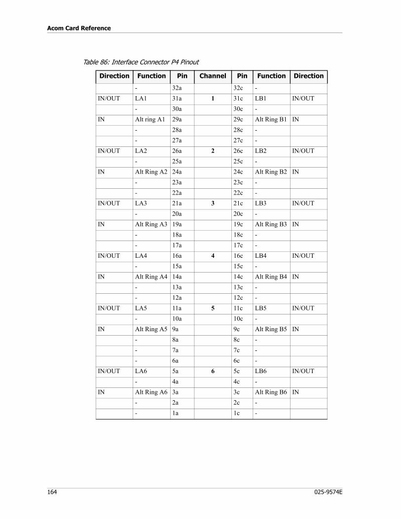
Acom Card Reference
164 025-9574E
Table 86: Interface Connector P4 Pinout
Direction Function Pin Channel Pin Function Direction
- 32a 32c -IN/OUT LA1 31a 1 31c LB1 IN/OUT
- 30a 30c -IN Alt ring A1 29a 29c Alt Ring B1 IN
- 28a 28c -- 27a 27c -
IN/OUT LA2 26a 2 26c LB2 IN/OUT- 25a 25c -
IN Alt Ring A2 24a 24c Alt Ring B2 IN- 23a 23c -- 22a 22c -
IN/OUT LA3 21a 3 21c LB3 IN/OUT- 20a 20c -
IN Alt Ring A3 19a 19c Alt Ring B3 IN- 18a 18c -- 17a 17c -
IN/OUT LA4 16a 4 16c LB4 IN/OUT- 15a 15c -
IN Alt Ring A4 14a 14c Alt Ring B4 IN- 13a 13c -- 12a 12c -
IN/OUT LA5 11a 5 11c LB5 IN/OUT- 10a 10c -
IN Alt Ring A5 9a 9c Alt Ring B5 IN- 8a 8c -- 7a 7c -- 6a 6c -
IN/OUT LA6 5a 6 5c LB6 IN/OUT- 4a 4c -
IN Alt Ring A6 3a 3c Alt Ring B6 IN- 2a 2c -- 1a 1c -
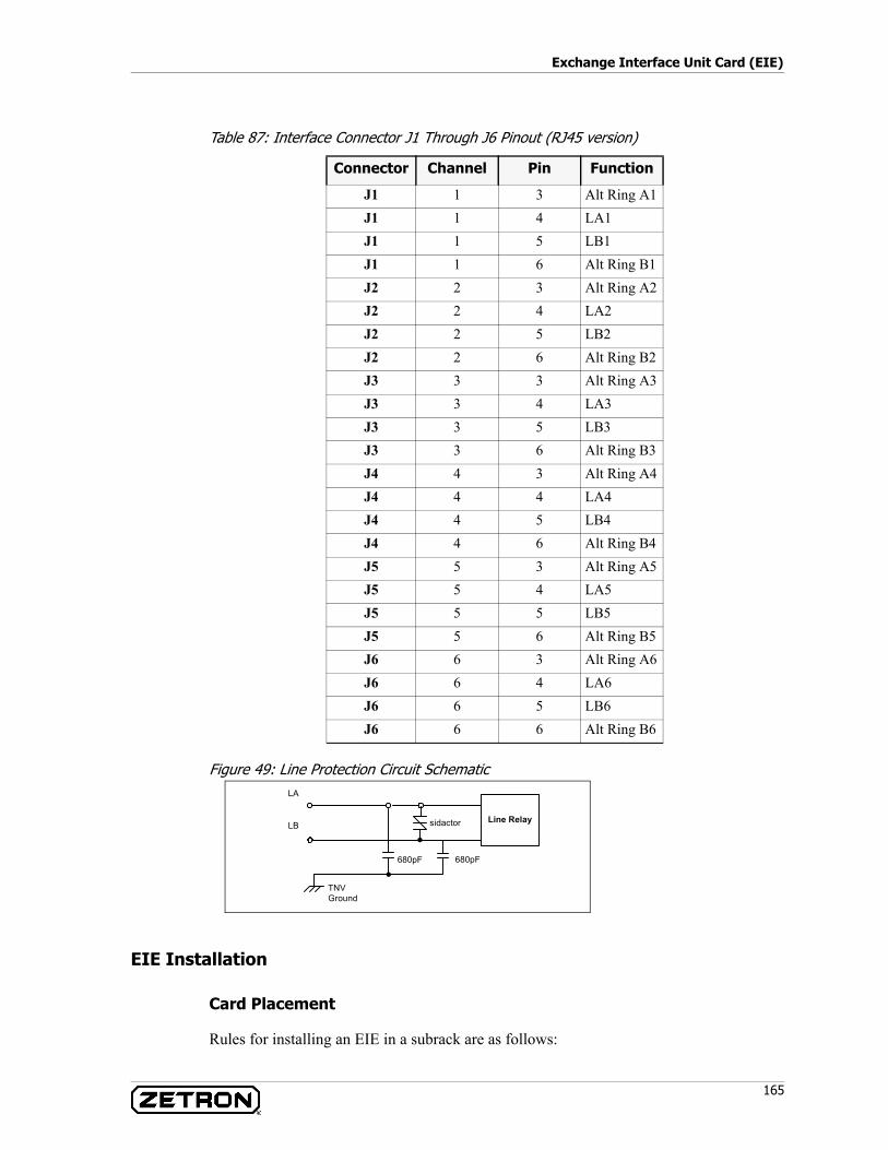
165
Exchange Interface Unit Card (EIE)
Table 87: Interface Connector J1 Through J6 Pinout (RJ45 version)
Figure 49: Line Protection Circuit Schematic
EIE Installation
Card Placement
Rules for installing an EIE in a subrack are as follows:
Connector Channel Pin Function
J1 1 3 Alt Ring A1J1 1 4 LA1J1 1 5 LB1J1 1 6 Alt Ring B1J2 2 3 Alt Ring A2J2 2 4 LA2J2 2 5 LB2J2 2 6 Alt Ring B2J3 3 3 Alt Ring A3J3 3 4 LA3J3 3 5 LB3J3 3 6 Alt Ring B3J4 4 3 Alt Ring A4J4 4 4 LA4J4 4 5 LB4J4 4 6 Alt Ring B4J5 5 3 Alt Ring A5J5 5 4 LA5J5 5 5 LB5J5 5 6 Alt Ring B5J6 6 3 Alt Ring A6J6 6 4 LA6J6 6 5 LB6J6 6 6 Alt Ring B6
LA
LB
680pF 680pF
TNVGround
Line Relaysidactor

Acom Card Reference
166 025-9574E
• The EIE card is hot-plug capable and may be removed or inserted with power applied to the rack.
• The EIE may be fitted to any slot in the subrack except slots 0, 1, and 12.
Line Impedance
The line impedance can be configured for each line through the system software. A 2-wire telephone line connected with a short cable has an impedance of 600 ohm (resistive). As the length of the line increases, the resistance and capacitance increase and the impedance becomes complex (i.e., combination of resistance / capacitance and/or inductive impedance). The EIE includes a switchable network that is intended to help the EIE match the impedance of longer lines. The EIE can select one of 16 options to help it match the impedance of longer lines.
Signaling
There are three signaling lines used to control and monitor the status of the EIE interfaces:• Ring detect• Loop out
When a ring voltage is detected, the line remains on-hook and mutes the audio paths.
The loop out circuit connects a load, which appears resistive at DC and is seen as high impedance AC. The loop circuit is used for decadic (pulse) dialing.
EIE Alarm Generation
The removal of a configured EIE, or the failure of a CODEC, will generate a Configuration Error (CE) alarm.
Table 88: EIE Alarms
EIE Technical Specifications
Table 89: Power Supply
Event Alarm Generated No Alarm TypeEIE Card Failure CE (Configuration Error) 0 UrgentEIE Card Removal CE (Configuration Error) 0 Urgent
Parameter Max Rating
Line Interface DC Voltage 60 VRing Voltage 100 VRMS
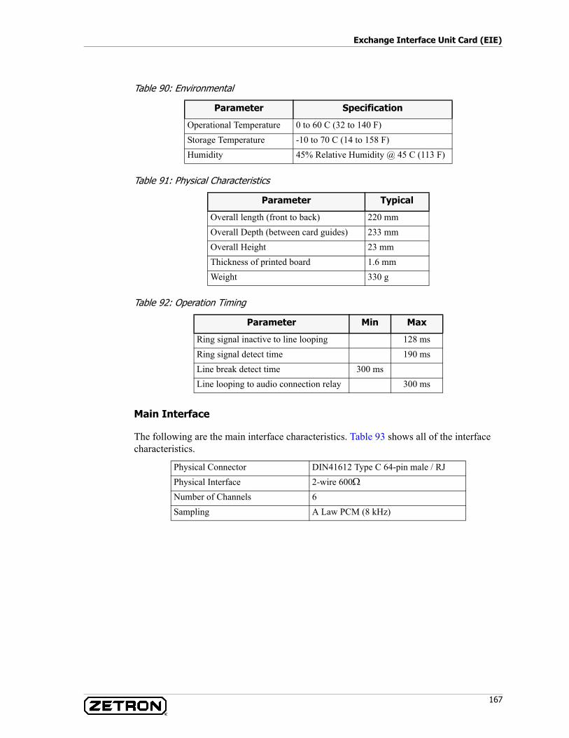
167
Exchange Interface Unit Card (EIE)
Table 90: Environmental
Table 91: Physical Characteristics
Table 92: Operation Timing
Main Interface
The following are the main interface characteristics. Table 93 shows all of the interface characteristics.
Parameter Specification
Operational Temperature 0 to 60 C (32 to 140 F)Storage Temperature -10 to 70 C (14 to 158 F)Humidity 45% Relative Humidity @ 45 C (113 F)
Parameter Typical
Overall length (front to back) 220 mmOverall Depth (between card guides) 233 mmOverall Height 23 mmThickness of printed board 1.6 mmWeight 330 g
Parameter Min Max
Ring signal inactive to line looping 128 msRing signal detect time 190 msLine break detect time 300 msLine looping to audio connection relay 300 ms
Physical Connector DIN41612 Type C 64-pin male / RJPhysical Interface 2-wire 600ΩNumber of Channels 6Sampling A Law PCM (8 kHz)
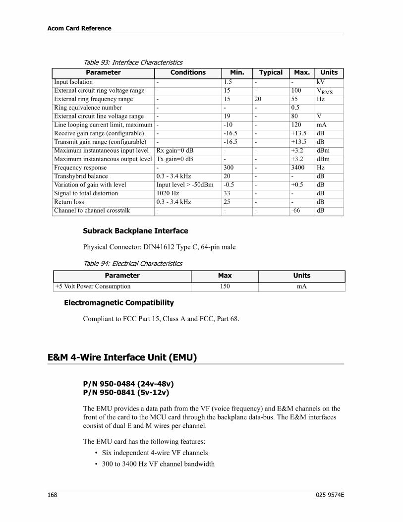
Acom Card Reference
168 025-9574E
Table 93: Interface Characteristics
Subrack Backplane Interface
Physical Connector: DIN41612 Type C, 64-pin male
Table 94: Electrical Characteristics
Electromagnetic Compatibility
Compliant to FCC Part 15, Class A and FCC, Part 68.
E&M 4-Wire Interface Unit (EMU)
P/N 950-0484 (24v-48v)P/N 950-0841 (5v-12v)
The EMU provides a data path from the VF (voice frequency) and E&M channels on the front of the card to the MCU card through the backplane data-bus. The E&M interfaces consist of dual E and M wires per channel.
The EMU card has the following features:• Six independent 4-wire VF channels• 300 to 3400 Hz VF channel bandwidth
Parameter Conditions Min. Typical Max. UnitsInput Isolation - 1.5 - - kVExternal circuit ring voltage range - 15 - 100 VRMSExternal ring frequency range - 15 20 55 HzRing equivalence number - - - 0.5External circuit line voltage range - 19 - 80 VLine looping current limit, maximum - -10 - 120 mAReceive gain range (configurable) - -16.5 - +13.5 dBTransmit gain range (configurable) - -16.5 - +13.5 dBMaximum instantaneous input level Rx gain=0 dB - - +3.2 dBmMaximum instantaneous output level Tx gain=0 dB - - +3.2 dBmFrequency response - 300 - 3400 HzTranshybrid balance 0.3 - 3.4 kHz 20 - - dBVariation of gain with level Input level > -50dBm -0.5 - +0.5 dBSignal to total distortion 1020 Hz 33 - - dBReturn loss 0.3 - 3.4 kHz 25 - - dBChannel to channel crosstalk - - - -66 dB
Parameter Max Units
+5 Volt Power Consumption 150 mA

169
E&M 4-Wire Interface Unit (EMU)
• 600Ω balanced (transformer coupled) VF inputs• Dual ‘E’ and ‘M’ leads per channel
EMU Block Diagram
Figure 50 shows the functional block diagram for an EMU.
Figure 50: EMU Functional Block Diagram
Description of Major Functional Blocks
The EMU is comprised of the major blocks described in Table 95.
Table 95: Description of EMU Functional Blocks
CODEC1/2
AudioTransmitCircuit
AudioReceiveCircuit
Signalling OutCircuits
LedDriver
Signalling
InCircuit
Debounce
TxATxB
RxARxB
So 1So 2
SI 1SI 2
So 1So 2SI 1SI 2
DIPSwitches
LEDEnable
ResetCircuit
SupplyFilters &
Regulation
+5 +12
-5 -12
BackplaneConnector
Note: For clarity, only one of six channels is shown.
Block Description
Audio Interface The audio interfaces consists of a two-wire transformer isolated 600Ω receive and transmit circuits.
Signaling Circuits The signaling in and signaling out circuits consist of optically coupled transistors and over-voltage protection.
Debounce A debounce circuit is used for noise discrimination on the signaling input lines. A pulse of less than 0.5 milliseconds duration on the signaling input lines will be rejected by the debounce circuit. (Debounce is also available using IMS software.)
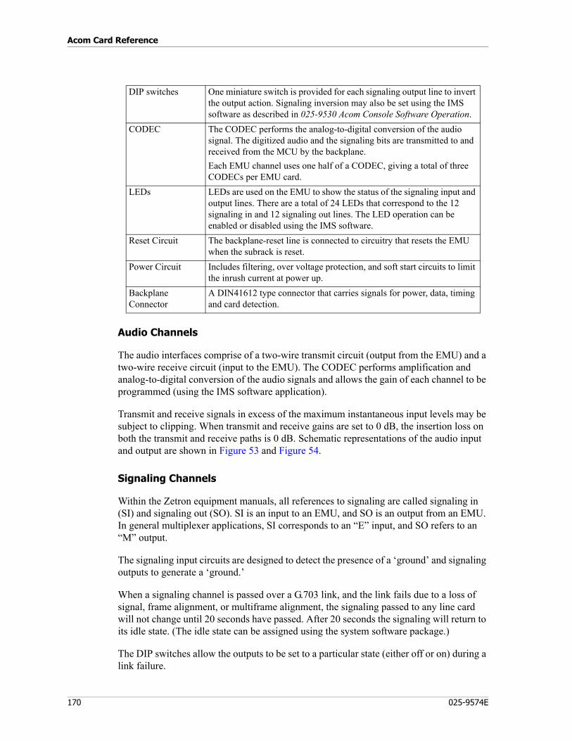
Acom Card Reference
170 025-9574E
Audio Channels
The audio interfaces comprise of a two-wire transmit circuit (output from the EMU) and a two-wire receive circuit (input to the EMU). The CODEC performs amplification and analog-to-digital conversion of the audio signals and allows the gain of each channel to be programmed (using the IMS software application).
Transmit and receive signals in excess of the maximum instantaneous input levels may be subject to clipping. When transmit and receive gains are set to 0 dB, the insertion loss on both the transmit and receive paths is 0 dB. Schematic representations of the audio input and output are shown in Figure 53 and Figure 54.
Signaling Channels
Within the Zetron equipment manuals, all references to signaling are called signaling in (SI) and signaling out (SO). SI is an input to an EMU, and SO is an output from an EMU. In general multiplexer applications, SI corresponds to an “E” input, and SO refers to an “M” output.
The signaling input circuits are designed to detect the presence of a ‘ground’ and signaling outputs to generate a ‘ground.’
When a signaling channel is passed over a G.703 link, and the link fails due to a loss of signal, frame alignment, or multiframe alignment, the signaling passed to any line card will not change until 20 seconds have passed. After 20 seconds the signaling will return to its idle state. (The idle state can be assigned using the system software package.)
The DIP switches allow the outputs to be set to a particular state (either off or on) during a link failure.
DIP switches One miniature switch is provided for each signaling output line to invert the output action. Signaling inversion may also be set using the IMS software as described in 025-9530 Acom Console Software Operation.
CODEC The CODEC performs the analog-to-digital conversion of the audio signal. The digitized audio and the signaling bits are transmitted to and received from the MCU by the backplane.Each EMU channel uses one half of a CODEC, giving a total of three CODECs per EMU card.
LEDs LEDs are used on the EMU to show the status of the signaling input and output lines. There are a total of 24 LEDs that correspond to the 12 signaling in and 12 signaling out lines. The LED operation can be enabled or disabled using the IMS software.
Reset Circuit The backplane-reset line is connected to circuitry that resets the EMU when the subrack is reset.
Power Circuit Includes filtering, over voltage protection, and soft start circuits to limit the inrush current at power up.
Backplane Connector
A DIN41612 type connector that carries signals for power, data, timing and card detection.
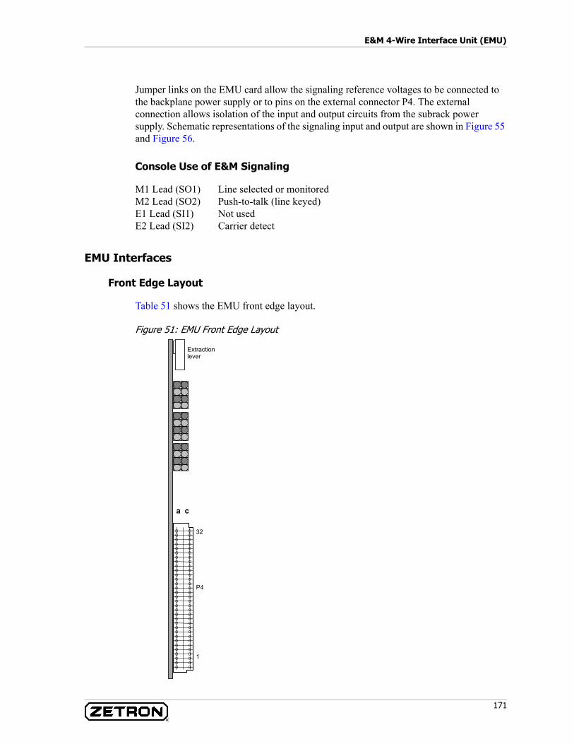
171
E&M 4-Wire Interface Unit (EMU)
Jumper links on the EMU card allow the signaling reference voltages to be connected to the backplane power supply or to pins on the external connector P4. The external connection allows isolation of the input and output circuits from the subrack power supply. Schematic representations of the signaling input and output are shown in Figure 55 and Figure 56.
Console Use of E&M Signaling
M1 Lead (SO1) Line selected or monitoredM2 Lead (SO2) Push-to-talk (line keyed)E1 Lead (SI1) Not usedE2 Lead (SI2) Carrier detect
EMU Interfaces
Front Edge Layout
Table 51 shows the EMU front edge layout.
Figure 51: EMU Front Edge Layout
a c
32
P4
1
Extractionlever
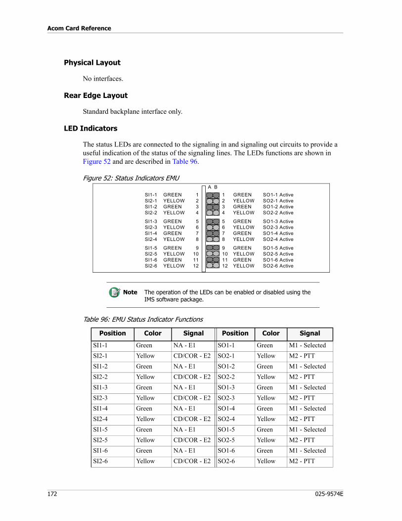
Acom Card Reference
172 025-9574E
Physical Layout
No interfaces.
Rear Edge Layout
Standard backplane interface only.
LED Indicators
The status LEDs are connected to the signaling in and signaling out circuits to provide a useful indication of the status of the signaling lines. The LEDs functions are shown in Figure 52 and are described in Table 96.
Figure 52: Status Indicators EMU
Table 96: EMU Status Indicator Functions
Note The operation of the LEDs can be enabled or disabled using the IMS software package.
A B1 GREEN SO1-1 Active2 YELLOW SO2-1 Active3 GREEN SO1-2 Active4 YELLOW SO2-2 Active
5 GREEN SO1-3 Active6 YELLOW SO2-3 Active7 GREEN SO1-4 Active8 YELLOW SO2-4 Active
9 GREEN SO1-5 Active10 YELLOW SO2-5 Active11 GREEN SO1-6 Active12 YELLOW SO2-6 Active
SI1-1 GREEN 1SI2-1 YELLOW 2SI1-2 GREEN 3SI2-2 YELLOW 4
SI1-3 GREEN 5SI2-3 YELLOW 6SI1-4 GREEN 7SI2-4 YELLOW 8
SI1-5 GREEN 9SI2-5 YELLOW 10SI1-6 GREEN 11SI2-6 YELLOW 12
Position Color Signal Position Color Signal
SI1-1 Green NA - E1 SO1-1 Green M1 - SelectedSI2-1 Yellow CD/COR - E2 SO2-1 Yellow M2 - PTTSI1-2 Green NA - E1 SO1-2 Green M1 - SelectedSI2-2 Yellow CD/COR - E2 SO2-2 Yellow M2 - PTTSI1-3 Green NA - E1 SO1-3 Green M1 - SelectedSI2-3 Yellow CD/COR - E2 SO2-3 Yellow M2 - PTTSI1-4 Green NA - E1 SO1-4 Green M1 - SelectedSI2-4 Yellow CD/COR - E2 SO2-4 Yellow M2 - PTTSI1-5 Green NA - E1 SO1-5 Green M1 - SelectedSI2-5 Yellow CD/COR - E2 SO2-5 Yellow M2 - PTTSI1-6 Green NA - E1 SO1-6 Green M1 - SelectedSI2-6 Yellow CD/COR - E2 SO2-6 Yellow M2 - PTT
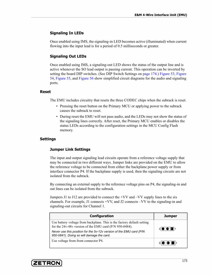
173
E&M 4-Wire Interface Unit (EMU)
Signaling In LEDs
Once enabled using IMS, the signaling-in LED becomes active (illuminated) when current flowing into the input lead is for a period of 0.5 milliseconds or greater.
Signaling Out LEDs
Once enabled using IMS, a signaling-out LED shows the status of the output line and is active whenever the SO lead output is passing current. This operation can be inverted by setting the board DIP switches. (See DIP Switch Settings on page 174.) Figure 53, Figure 54, Figure 55, and Figure 56 show simplified circuit diagrams for the audio and signaling ports.
Reset
The EMU includes circuitry that resets the three CODEC chips when the subrack is reset.• Pressing the reset button on the Primary MCU or applying power to the subrack
causes the subrack to reset.• During reset the EMU will not pass audio, and the LEDs may not show the status of
the signaling lines correctly. After reset, the Primary MCU enables or disables the status LEDs according to the configuration settings in the MCU Config Flash memory.
Settings
Jumper Link Settings
The input and output signaling lead circuits operate from a reference voltage supply that may be connected in two different ways. Jumper links are provided on the EMU to allow the reference voltage to be connected from either the backplane power supply or from interface connector P4. If the backplane supply is used, then the signaling circuits are not isolated from the subrack.
By connecting an external supply to the reference voltage pins on P4, the signaling-in and out lines can be isolated from the subrack.
Jumpers J1 to J12 are provided to connect the +VV and –VV supply lines to the six channels. For example, J1 connects +VV, and J2 connects –VV to the signaling-in and signaling-out circuits for Channel 1.
Configuration Jumper
Use battery voltage from backplane. This is the factory default setting for the 24v-48v version of the EMU card (P/N 950-0484).Never use this position for the 5v-12v version of the EMU card (P/N950-0841). Doing so will damage the card.
Use voltage from front connector P4.
3 1
3 1
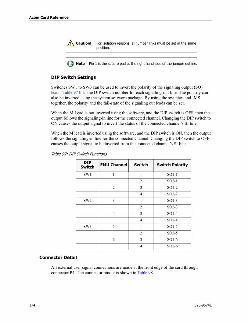
Acom Card Reference
174 025-9574E
DIP Switch Settings
Switches SW1 to SW3 can be used to invert the polarity of the signaling output (SO) leads. Table 97 lists the DIP switch number for each signaling-out line. The polarity can also be inverted using the system software package. By using the switches and IMS together, the polarity and the fail-state of the signaling out leads can be set.
When the M Lead is not inverted using the software, and the DIP switch is OFF, then the output follows the signaling-in line for the connected channel. Changing the DIP switch to ON causes the output signal to invert the status of the connected channel’s SI line.
When the M lead is inverted using the software, and the DIP switch is ON, then the output follows the signaling-in line for the connected channel. Changing the DIP switch to OFF causes the output signal to be inverted from the connected channel’s SI line.
Table 97: DIP Switch Functions
Connector Detail
All external user signal connections are made at the front edge of the card through connector P4. The connector pinout is shown in Table 98.
Caution! For isolation reasons, all jumper links must be set in the same position.
Note Pin 1 is the square pad at the right hand side of the jumper outline.
DIP Switch EMU Channel Switch Switch Polarity
SW1 1 1 SO1-12 SO2-1
2 3 SO1-24 SO2-2
SW2 3 1 SO1-32 SO2-3
4 3 SO1-44 SO2-4
SW3 5 1 SO1-52 SO2-5
6 3 SO1-64 SO2-6
!
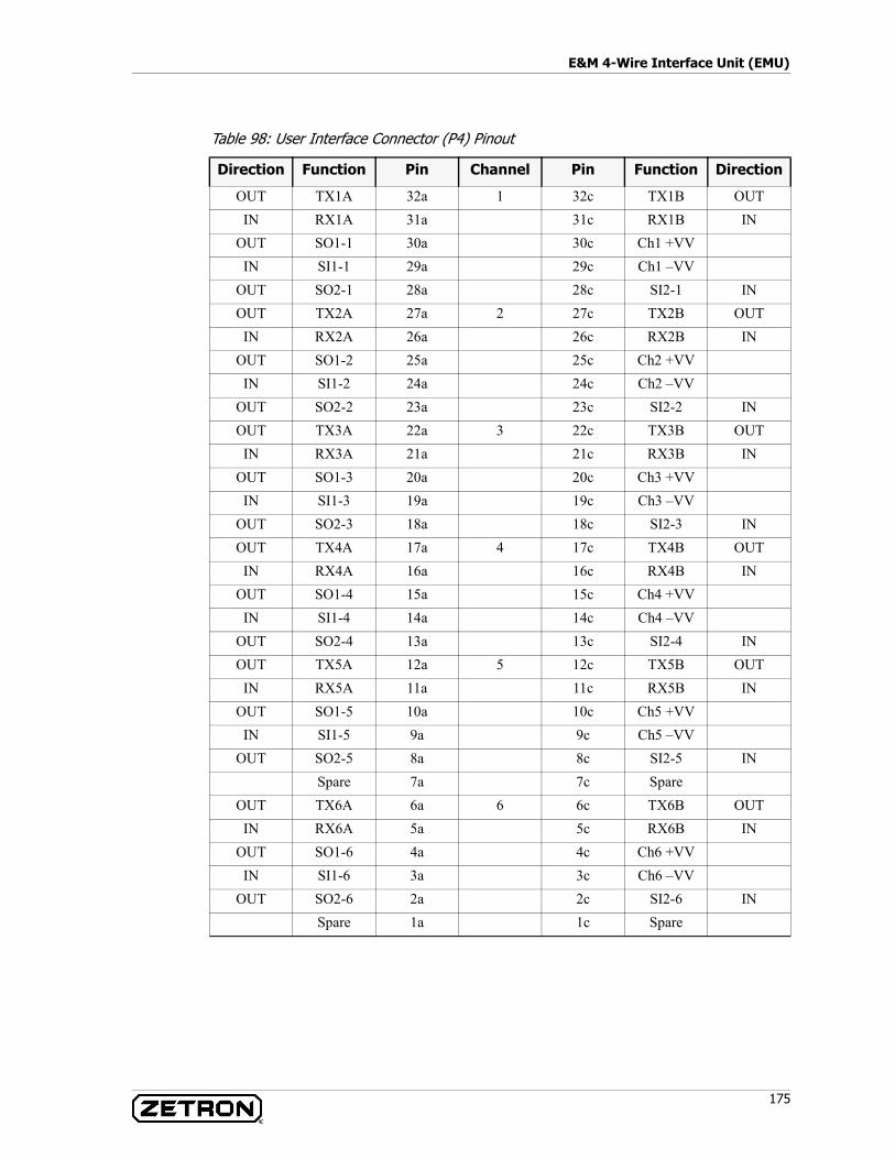
175
E&M 4-Wire Interface Unit (EMU)
Table 98: User Interface Connector (P4) Pinout
Direction Function Pin Channel Pin Function Direction
OUT TX1A 32a 1 32c TX1B OUTIN RX1A 31a 31c RX1B IN
OUT SO1-1 30a 30c Ch1 +VVIN SI1-1 29a 29c Ch1 –VV
OUT SO2-1 28a 28c SI2-1 INOUT TX2A 27a 2 27c TX2B OUT
IN RX2A 26a 26c RX2B INOUT SO1-2 25a 25c Ch2 +VV
IN SI1-2 24a 24c Ch2 –VVOUT SO2-2 23a 23c SI2-2 INOUT TX3A 22a 3 22c TX3B OUT
IN RX3A 21a 21c RX3B INOUT SO1-3 20a 20c Ch3 +VV
IN SI1-3 19a 19c Ch3 –VVOUT SO2-3 18a 18c SI2-3 INOUT TX4A 17a 4 17c TX4B OUT
IN RX4A 16a 16c RX4B INOUT SO1-4 15a 15c Ch4 +VV
IN SI1-4 14a 14c Ch4 –VVOUT SO2-4 13a 13c SI2-4 INOUT TX5A 12a 5 12c TX5B OUT
IN RX5A 11a 11c RX5B INOUT SO1-5 10a 10c Ch5 +VV
IN SI1-5 9a 9c Ch5 –VVOUT SO2-5 8a 8c SI2-5 IN
Spare 7a 7c SpareOUT TX6A 6a 6 6c TX6B OUT
IN RX6A 5a 5c RX6B INOUT SO1-6 4a 4c Ch6 +VV
IN SI1-6 3a 3c Ch6 –VVOUT SO2-6 2a 2c SI2-6 IN
Spare 1a 1c Spare
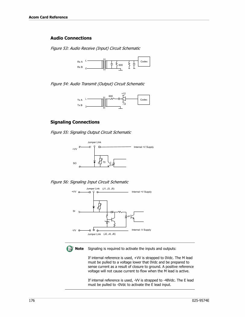
Acom Card Reference
176 025-9574E
Audio Connections
Figure 53: Audio Receive (Input) Circuit Schematic
Figure 54: Audio Transmit (Output) Circuit Schematic
Signaling Connections
Figure 55: Signaling Output Circuit Schematic
Figure 56: Signaling Input Circuit Schematic
Note Signaling is required to activate the inputs and outputs:
If internal reference is used, +VV is strapped to 0Vdc. The M lead must be pulled to a voltage lower that 0Vdc and be prepared to sense current as a result of closure to ground. A positive reference voltage will not cause current to flow when the M lead is active.
If internal reference is used, -VV is strapped to -48Vdc. The E lead must be pulled to -0Vdc to activate the E lead input.
Rx A
Rx B600
Codec
+12
Tx A
Tx B
600Codec
-12
+VV
SO
Jumper LInk
Internal +V Supply
70
Internal -V Supply
+VV
SI
Jumper LinkInternal +V Supply
Jumper Link-VV
(J1, J3, J5)
(J2, J4, J6)

177
E&M 4-Wire Interface Unit (EMU)
EMU Installation
Card Placement
Rules for installation of an EMU in a subrack are as follows:• The EMU card is hot pluggable and may be removed or inserted while power is
applied to the rack. • The EMU may be fitted to any slot in the subrack except slots 0, 1, and 12.
Listen-in Line Support
Listen-in Line Support is a custom option when using Acom with a 3200 system. With Listen-in Line Support, Acom can listen (receive only) to positions connected to the 3200 system.
Listen-in Line Support is installed by connecting Acom EMU cards to the position logger outputs on the 3200 (the RJ21 logger ports on station card shelves). A Krone block is used for phone isolation, which isolates M3200 Logger output from Acom EMU 600ohm input as shown in the following diagram:
Installation of Listen-in Line Support is custom. Refer to the following documents:• E&M 4-Wire Interface Unit (EMU) on page 168 of this manual• S3200 Installation Manual (P/N 025-9419)• 3200 Listen-in Wiring Diagram (P/N 045-0278-077-03)
EMU Alarm Generation
The failure of a CODEC, the interface from the CODEC to the backplane, or the removal of the EMU from the rack, will generate a configuration alarm. The EMU generates no other alarms.
Table 99: EMU Alarms
1 2 3 4 5 6 7 8 9 0
K R O N E
1a - Tip IN1b - Ring IN2a - Tip OUT2b - NC3a - Ring OUT
Event Alarm Generated No Alarm Type
EMU Card Failure CE (Configuration Error) 0 UrgentEMU Card Removal CE (Configuration Error) 0 UrgentCODEC Failure CE (Configuration Error) 0 UrgentFailure of interface between CODEC and backplane
CE (Configuration Error) 0 Urgent
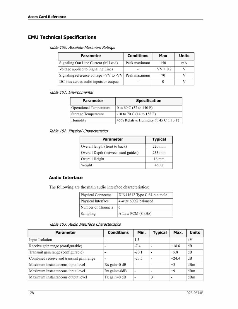
Acom Card Reference
178 025-9574E
EMU Technical Specifications
Table 100: Absolute Maximum Ratings
Table 101: Environmental
Table 102: Physical Characteristics
Audio Interface
The following are the main audio interface characteristics:
Table 103: Audio Interface Characteristics
Parameter Conditions Max Units
Signaling Out Line Current (M Lead) Peak maximum 150 mAVoltage applied to Signaling Lines - +VV + 0.2 VSignaling reference voltage +VV to -VV Peak maximum 70 VDC bias across audio inputs or outputs - 0 V
Parameter Specification
Operational Temperature 0 to 60 C (32 to 140 F)Storage Temperature -10 to 70 C (14 to 158 F)Humidity 45% Relative Humidity @ 45 C (113 F)
Parameter Typical
Overall length (front to back) 220 mmOverall Depth (between card guides) 233 mmOverall Height 16 mmWeight 460 g
Physical Connector DIN41612 Type C 64-pin malePhysical Interface 4-wire 600Ω balancedNumber of Channels 6Sampling A Law PCM (8 kHz)
Parameter Conditions Min. Typical Max. Units
Input Isolation - 1.5 - - kVReceive gain range (configurable) - -7.4 - +18.6 dBTransmit gain range (configurable) - -20.1 - +5.8 dBCombined receive and transmit gain range - -27.5 - +24.4 dBMaximum instantaneous input level Rx gain=0 dB - - +3 dBmMaximum instantaneous input level Rx gain=-6dB - - +9 dBmMaximum instantaneous output level Tx gain=0 dB - 3 - dBm
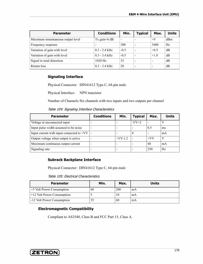
179
E&M 4-Wire Interface Unit (EMU)
Signaling Interface
Physical Connector: DIN41612 Type C, 64-pin male
Physical Interface: NPN transistor
Number of Channels:Six channels with two inputs and two outputs per channel
Table 104: Signaling Interface Characteristics
Subrack Backplane Interface
Physical Connector: DIN41612 Type C, 64-pin male
Table 105: Electrical Characteristics
Electromagnetic Compatibility
Compliant to AS3548, Class B and FCC Part 15, Class A.
Maximum instantaneous output level Tx gain=6 dB - - +9 dBmFrequency response - 300 - 3400 HzVariation of gain with level 0.3 - 2.4 kHz -0.5 - +0.5 dBVariation of gain with level 0.3 - 3.4 kHz -0.5 - +1.8 dBSignal to total distortion 1020 Hz 33 - - dBReturn loss 0.3 - 3.4 kHz 20 - - dB
Parameter Conditions Min. Typical Max. Units
Parameter Conditions Min. Typical Max. Units
Voltage at unconnected input - - -VV+2 - VInput pulse width assumed to be noise - - - 0.5 msInput current with input connected to +VV - - 4 - mAOutput voltage when output is active - +VV-1.2 - +VV VMaximum continuous output current - - - 60 mASignaling rate - - - 250 Hz
Parameter Min. Max. Units
+5 Volt Power Consumption 60 200 mA+12 Volt Power Consumption 5 10 mA-12 Volt Power Consumption 35 60 mA
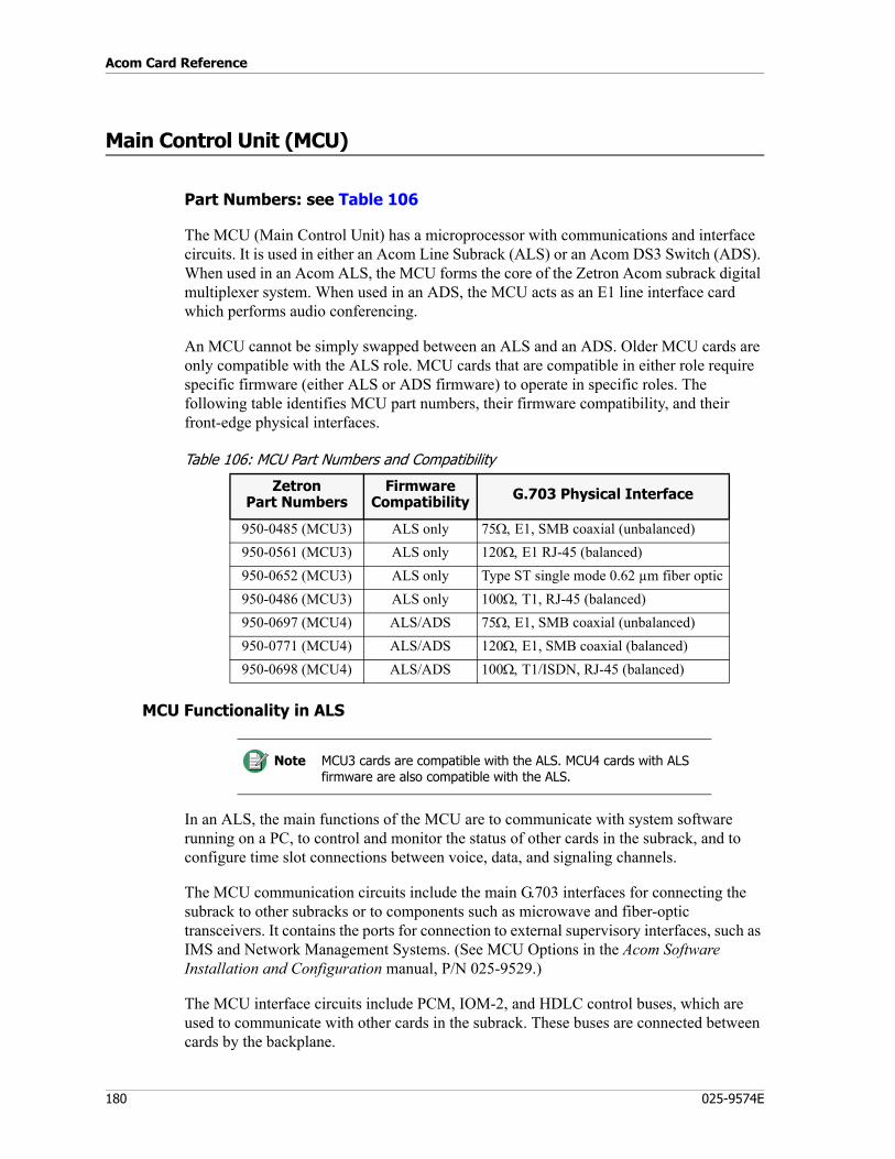
Acom Card Reference
180 025-9574E
Main Control Unit (MCU)
Part Numbers: see Table 106
The MCU (Main Control Unit) has a microprocessor with communications and interface circuits. It is used in either an Acom Line Subrack (ALS) or an Acom DS3 Switch (ADS). When used in an Acom ALS, the MCU forms the core of the Zetron Acom subrack digital multiplexer system. When used in an ADS, the MCU acts as an E1 line interface card which performs audio conferencing.
An MCU cannot be simply swapped between an ALS and an ADS. Older MCU cards are only compatible with the ALS role. MCU cards that are compatible in either role require specific firmware (either ALS or ADS firmware) to operate in specific roles. The following table identifies MCU part numbers, their firmware compatibility, and their front-edge physical interfaces.
Table 106: MCU Part Numbers and Compatibility
MCU Functionality in ALS
In an ALS, the main functions of the MCU are to communicate with system software running on a PC, to control and monitor the status of other cards in the subrack, and to configure time slot connections between voice, data, and signaling channels.
The MCU communication circuits include the main G.703 interfaces for connecting the subrack to other subracks or to components such as microwave and fiber-optic transceivers. It contains the ports for connection to external supervisory interfaces, such as IMS and Network Management Systems. (See MCU Options in the Acom Software Installation and Configuration manual, P/N 025-9529.)
The MCU interface circuits include PCM, IOM-2, and HDLC control buses, which are used to communicate with other cards in the subrack. These buses are connected between cards by the backplane.
ZetronPart Numbers
Firmware Compatibility G.703 Physical Interface
950-0485 (MCU3) ALS only 75Ω, E1, SMB coaxial (unbalanced)950-0561 (MCU3) ALS only 120Ω, E1 RJ-45 (balanced)950-0652 (MCU3) ALS only Type ST single mode 0.62 µm fiber optic950-0486 (MCU3) ALS only 100Ω, T1, RJ-45 (balanced)950-0697 (MCU4) ALS/ADS 75Ω, E1, SMB coaxial (unbalanced)950-0771 (MCU4) ALS/ADS 120Ω, E1, SMB coaxial (balanced)950-0698 (MCU4) ALS/ADS 100Ω, T1/ISDN, RJ-45 (balanced)
Note MCU3 cards are compatible with the ALS. MCU4 cards with ALS firmware are also compatible with the ALS.
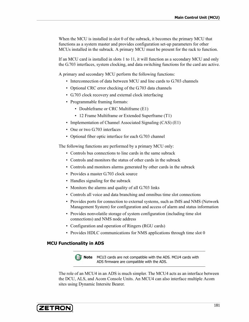
181
Main Control Unit (MCU)
When the MCU is installed in slot 0 of the subrack, it becomes the primary MCU that functions as a system master and provides configuration set-up parameters for other MCUs installed in the subrack. A primary MCU must be present for the rack to function.
If an MCU card is installed in slots 1 to 11, it will function as a secondary MCU and only the G.703 interfaces, system clocking, and data switching functions for the card are active.
A primary and secondary MCU perform the following functions:• Interconnection of data between MCU and line cards to G.703 channels• Optional CRC error checking of the G.703 data channels• G.703 clock recovery and external clock interfacing• Programmable framing formats:
• Doubleframe or CRC Multiframe (E1)• 12 Frame Multiframe or Extended Superframe (T1)
• Implementation of Channel Associated Signaling (CAS) (E1)• One or two G.703 interfaces• Optional fiber optic interface for each G.703 channel
The following functions are performed by a primary MCU only:• Controls bus connections to line cards in the same subrack• Controls and monitors the status of other cards in the subrack• Controls and monitors alarms generated by other cards in the subrack• Provides a master G.703 clock source• Handles signaling for the subrack• Monitors the alarms and quality of all G.703 links• Controls all voice and data branching and omnibus time slot connections• Provides ports for connection to external systems, such as IMS and NMS (Network
Management System) for configuration and access of alarm and status information• Provides nonvolatile storage of system configuration (including time slot
connections) and NMS node address• Configuration and operation of Ringers (RGU cards)• Provides HDLC communications for NMS applications through time slot 0
MCU Functionality in ADS
The role of an MCU4 in an ADS is much simpler. The MCU4 acts as an interface between the DCU, ALS, and Acom Console Units. An MCU4 can also interface multiple Acom sites using Dynamic Intersite Bearer.
Note MCU3 cards are not compatible with the ADS. MCU4 cards with ADS firmware are compatible with the ADS.
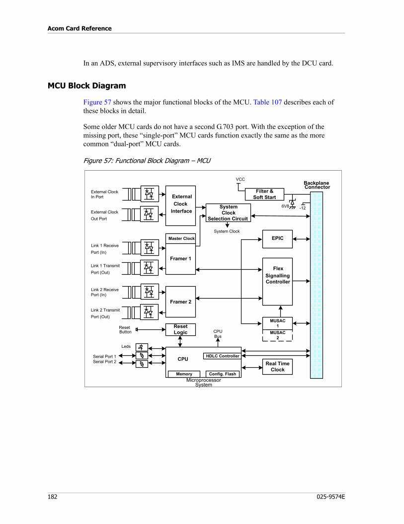
Acom Card Reference
182 025-9574E
In an ADS, external supervisory interfaces such as IMS are handled by the DCU card.
MCU Block Diagram
Figure 57 shows the major functional blocks of the MCU. Table 107 describes each of these blocks in detail.
Some older MCU cards do not have a second G.703 port. With the exception of the missing port, these “single-port” MCU cards function exactly the same as the more common “dual-port” MCU cards.
Figure 57: Functional Block Diagram – MCU
FlexSignallingController
Real TimeClock
CPUBus
Framer 2
MUSAC2
MicroprocessorSystem
Memory Config. Flash
HDLC ControllerCPU
MUSAC1
EPIC
Serial Port 1Serial Port 2
Leds
ResetLogic
ResetButton
Framer 1
Master ClockLink 1 ReceivePort (In)
Link 1 TransmitPort (Out)
Link 2 ReceivePort (In)
Link 2 TransmitPort (Out)
VCC
SystemClock
Selection Circuit
BackplaneConnector
Filter &Soft Start
-126V8
ExternalClock
Interface
External ClockIn Port
External ClockOut Port
System Clock

183
Main Control Unit (MCU)
Description of Major Functional Blocks
Table 107: Description of MCU Major Functional Blocks
BLOCK DESCRIPTION
MUSAC The MUSAC is a cross-point switch responsible for the time slot connections and conferencing of channels on all internal G.703 buses up-to a maximum of 14 streams (512 time slots).
Framers The Framers process the frame in accordance with G.704 and provide electrical interfaces for the G.703 signals. There is one framer per each G.703 link. The Framer circuit performs clock recovery, AIS injection, CAS signaling, remote alarm generation, CRC error handling, transmit line monitoring, local loopback connection, error monitoring and alarm simulation.
Line Transformers Provide electrical isolation between the Framers and the external line connections and diodes for over-voltage protection.
Microprocessor System
The microprocessor system combines a CPU, memory, watchdog timer and reset circuitry to provide overall management of the MCU. Configuration settings are stored in the Config Flash memory. The MCU includes software routines to check the program memory checksum and to check for the presence of the Config Flash memory. The microprocessor system includes reset circuitry, which is controlled by the reset push button and the CPU.
Config Flash Memory
Memory used to store two sets of configuration parameters such as time slot connections, address, clocking sources, etc., and to store fault logs.
LEDs Sixteen Status indicators for monitoring the status of links, ringers, alarms and MCU operation.
Serial Port 1 (X17) Serial port 1 is an RS-232 port typically used for communication with the Microprocessor System. Configuration of software parameters can be achieved by connecting a personal computer with the IMS software package to this port. The serial port itself can be configured (see the section “Serial Port” in Acom Software Installation and Configuration, P/N 025-9529)
Serial Port 2 (X18) Serial port 2 is normally supplied configured as RS-485 full duplex with no collision detection. The default setting for this port is no operation. This port is typically used to feed an external clock signal into the MCU/system. The serial port can be configured (see the section “Serial Port” in Acom Software Installation and Configuration, P/N 025-9529)
Real Time Clock A 24-hour clock and calendar with leap year correction.Flex Signaling Controller
Processes all signaling for the MCU and provides signaling inversion when configured using system software. Provides a time slot connection path from the backplane to the MUSAC, EPIC and Framers.
EPIC The EPIC allows the MCU to detect, configure and interface to CODEC based line cards.
Master Clock The Master Clock is a free running crystal oscillator.External Clock Interface
Supplies an ITU G.703 standard (clause 10), external G.703 synchronization clock input and output.
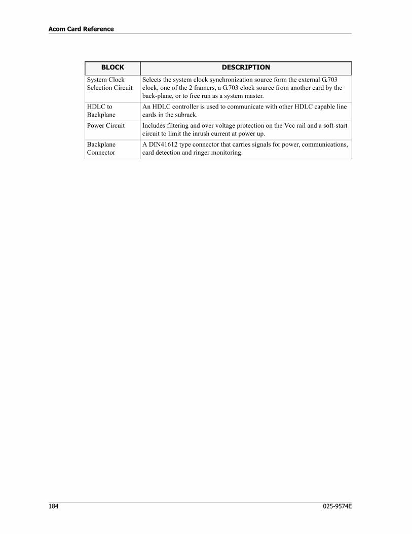
Acom Card Reference
184 025-9574E
System Clock Selection Circuit
Selects the system clock synchronization source form the external G.703 clock, one of the 2 framers, a G.703 clock source from another card by the back-plane, or to free run as a system master.
HDLC to Backplane
An HDLC controller is used to communicate with other HDLC capable line cards in the subrack.
Power Circuit Includes filtering and over voltage protection on the Vcc rail and a soft-start circuit to limit the inrush current at power up.
Backplane Connector
A DIN41612 type connector that carries signals for power, communications, card detection and ringer monitoring.
BLOCK DESCRIPTION
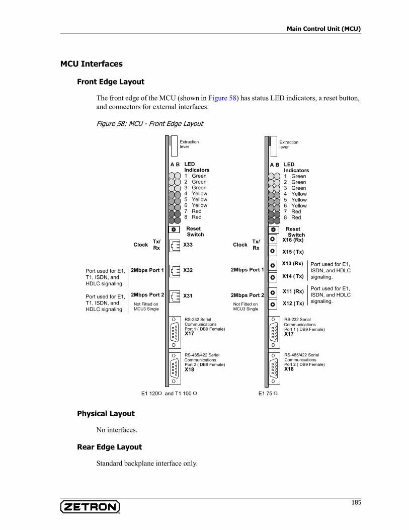
185
Main Control Unit (MCU)
MCU Interfaces
Front Edge Layout
The front edge of the MCU (shown in Figure 58) has status LED indicators, a reset button, and connectors for external interfaces.
Figure 58: MCU - Front Edge Layout
Physical Layout
No interfaces.
Rear Edge Layout
Standard backplane interface only.
Clock Tx/Rx
X32
X31
A B
ResetSwitch
RS-232 SerialCommunicationsPort 1 ( DB9 Female)X17
LEDIndicators1 Green2 Green3 Green4 Yellow5 Yellow6 Yellow7 Red8 Red
Extractionlever
RS-485/422 SerialCommunicationsPort 2 ( DB9 Female)X18
X33
2Mbps Port 1
2Mbps Port 2
X13 (Rx)
Clock Tx/Rx
X14 ( Tx)
X11 (Rx)
X12 (Tx)
A B
ResetSwitch
RS-232 SerialCommunicationsPort 1 ( DB9 Female)X17
LEDIndicators1 Green2 Green3 Green4 Yellow5 Yellow6 Yellow7 Red8 Red
Extractionlever
RS-485/422 SerialCommunicationsPort 2 ( DB9 Female)X18
X15 ( Tx)
2Mbps Port 1
2Mbps Port 2
X16 (Rx)
Not Fitted onMCU3 Single
E1 120Ω and T1 100 Ω E1 75 Ω
Not Fitted onMCU3 Single
Port used for E1,ISDN, and HDLCsignaling.
Port used for E1,ISDN, and HDLCsignaling.
Port used for E1,T1, ISDN, andHDLC signaling.
Port used for E1,T1, ISDN, andHDLC signaling.
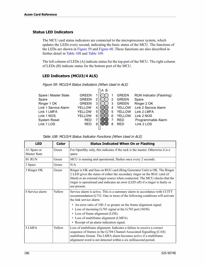
Acom Card Reference
186 025-9574E
Status LED Indicators
The MCU card status indicators are connected to the microprocessor system, which updates the LEDs every second, indicating the basic status of the MCU. The functions of the LEDs are shown in Figure 59 and Figure 60. These functions are also described in further detail in Table 108 and Table 109.
The left column of LEDs (A) indicate status for the top port of the MCU. The right column of LEDs (B) indicate status for the bottom port of the MCU.
LED Indicators (MCU3/4 ALS)
Figure 59: MCU3/4 Status Indicators (When Used in ALS)
Table 108: MCU3/4 Status Indicator Functions (When Used in ALS)
A B1 GREEN RUN Indicator (Flashing)2 GREEN Spare3 GREEN Ringer 2 OK4 YELLOW Link 2 Service Alarm5 YELLOW Link 2 LMFA6 YELLOW Link 2 NOS7 RED Programmable Alarm8 RED Link 2 LOS
Spare / Master State GREEN 1Spare GREEN 2Ringer 1 OK GREEN 3Link 1 Service Alarm YELLOW 4Link 1 LMFA YELLOW 5Link 1 NOS YELLOW 6System Reset RED 7Link 1 LOS RED 8
LED Color Status Indicated When On or Flashing
A1 Spare orMaster State
Green For OpenSky only, this indicates if the rack is the master. Otherwise it is a spare.
B1 RUN Green MCU is running and operational, flashes once every 2 seconds.2 Spare Green N/A3 Ringer OK Green Ringer is OK and fuse on RGU card (Ring Generator Unit) is OK. The Ringer
2 LED gives the status of either the secondary ringer on the RGU card (if fitted) or an external ringer source when connected. The MCU checks that the ringer is operational and indicates an error (LED off) if a ringer is faulty or not present.
4 Service alarm Yellow Service alarm is active. This is a summary alarm in accordance with CCITT recommendation G.732. One or more of the following conditions will activate the link service alarm:
• An error ratio of 10E-3 or greater on the frame alignment signal.• Loss of incoming G.703 signal at the G.703 port (NOS).• Loss of frame alignment (LOS).• Loss of multiframe alignment (LMFA).• Receipt of an alarm indication signal.
5 LMFA Yellow Loss of multiframe alignment. Indicates a failure to receive a correct sequence of frames in the G.704 Channel Associated Signalling (CAS) multiframe format. The LMFA alarm becomes active if a multiframe alignment word is not detected within a six millisecond period.
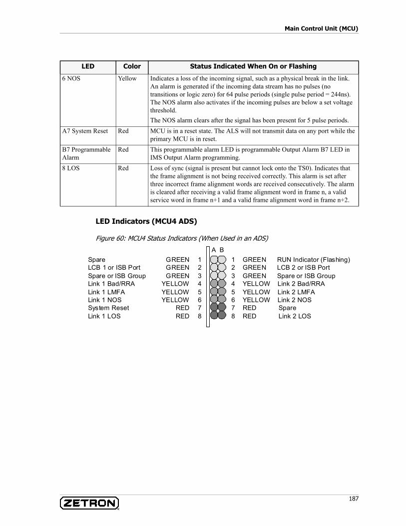
187
Main Control Unit (MCU)
LED Indicators (MCU4 ADS)
Figure 60: MCU4 Status Indicators (When Used in an ADS)
6 NOS Yellow Indicates a loss of the incoming signal, such as a physical break in the link. An alarm is generated if the incoming data stream has no pulses (no transitions or logic zero) for 64 pulse periods (single pulse period = 244ns). The NOS alarm also activates if the incoming pulses are below a set voltage threshold.The NOS alarm clears after the signal has been present for 5 pulse periods.
A7 System Reset Red MCU is in a reset state. The ALS will not transmit data on any port while the primary MCU is in reset.
B7 Programmable Alarm
Red This programmable alarm LED is programmable Output Alarm B7 LED in IMS Output Alarm programming.
8 LOS Red Loss of sync (signal is present but cannot lock onto the TS0). Indicates that the frame alignment is not being received correctly. This alarm is set after three incorrect frame alignment words are received consecutively. The alarm is cleared after receiving a valid frame alignment word in frame n, a valid service word in frame n+1 and a valid frame alignment word in frame n+2.
LED Color Status Indicated When On or Flashing
A B 1 GREEN RUN Indicator (Flashing) 2 GREEN LCB 2 or ISB Port 3 GREEN Spare or ISB Group 4 YELLOW Link 2 Bad/RRA 5 YELLOW Link 2 LMFA 6 YELLOW Link 2 NOS 7 RED Spare 8 RED Link 2 LOS
Spare GREEN 1 LCB 1 or ISB Port GREEN 2 Spare or ISB Group GREEN 3 Link 1 Bad/RRA YELLOW 4 Link 1 LMFA YELLOW 5 Link 1 NOS YELLOW 6 System Reset RED 7 Link 1 LOS RED 8
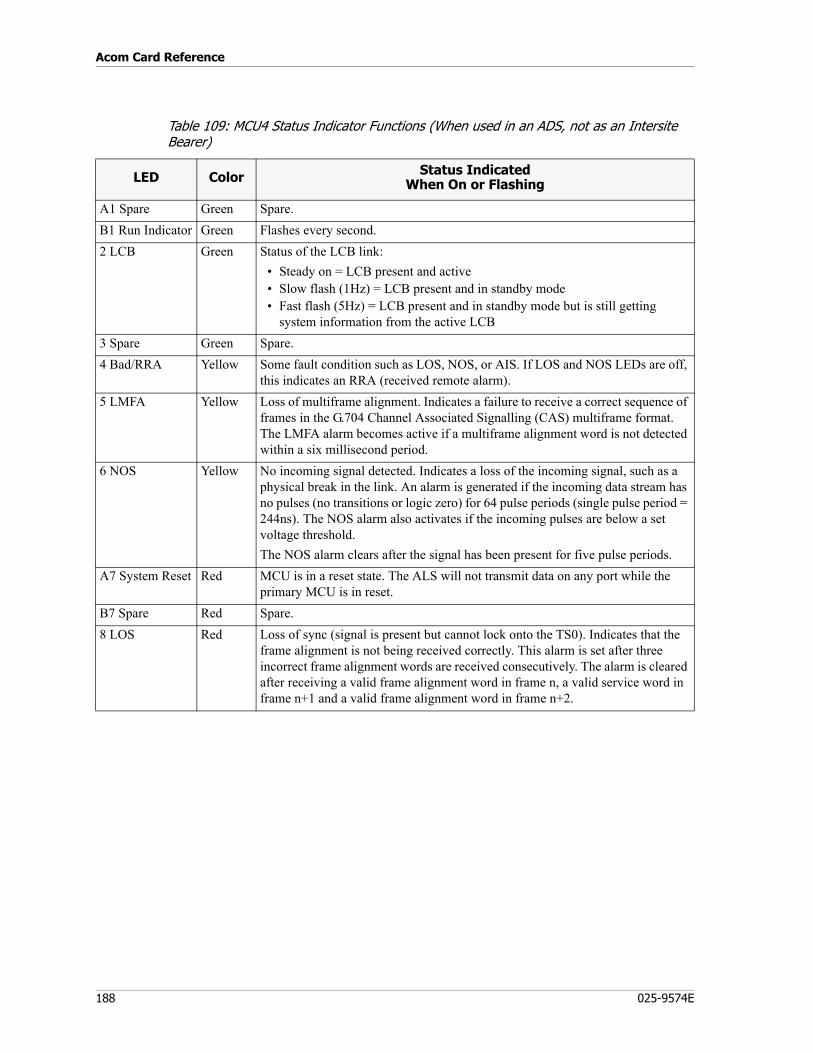
Acom Card Reference
188 025-9574E
Table 109: MCU4 Status Indicator Functions (When used in an ADS, not as an Intersite Bearer)
LED Color Status IndicatedWhen On or Flashing
A1 Spare Green Spare.B1 Run Indicator Green Flashes every second.2 LCB Green Status of the LCB link:
• Steady on = LCB present and active• Slow flash (1Hz) = LCB present and in standby mode• Fast flash (5Hz) = LCB present and in standby mode but is still getting
system information from the active LCB3 Spare Green Spare.4 Bad/RRA Yellow Some fault condition such as LOS, NOS, or AIS. If LOS and NOS LEDs are off,
this indicates an RRA (received remote alarm).5 LMFA Yellow Loss of multiframe alignment. Indicates a failure to receive a correct sequence of
frames in the G.704 Channel Associated Signalling (CAS) multiframe format. The LMFA alarm becomes active if a multiframe alignment word is not detected within a six millisecond period.
6 NOS Yellow No incoming signal detected. Indicates a loss of the incoming signal, such as a physical break in the link. An alarm is generated if the incoming data stream has no pulses (no transitions or logic zero) for 64 pulse periods (single pulse period = 244ns). The NOS alarm also activates if the incoming pulses are below a set voltage threshold.The NOS alarm clears after the signal has been present for five pulse periods.
A7 System Reset Red MCU is in a reset state. The ALS will not transmit data on any port while the primary MCU is in reset.
B7 Spare Red Spare.8 LOS Red Loss of sync (signal is present but cannot lock onto the TS0). Indicates that the
frame alignment is not being received correctly. This alarm is set after three incorrect frame alignment words are received consecutively. The alarm is cleared after receiving a valid frame alignment word in frame n, a valid service word in frame n+1 and a valid frame alignment word in frame n+2.
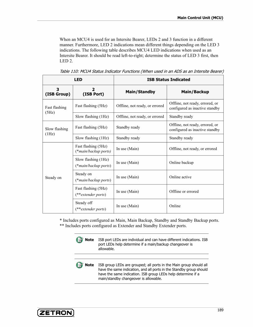
189
Main Control Unit (MCU)
When an MCU4 is used for an Intersite Bearer, LEDs 2 and 3 function in a different manner. Furthermore, LED 2 indications mean different things depending on the LED 3 indications. The following table describes MCU4 LED indications when used as an Intersite Bearer. It should be read left-to-right; determine the status of LED 3 first, then LED 2.
Table 110: MCU4 Status Indicator Functions (When used in an ADS as an Intersite Bearer)
* Includes ports configured as Main, Main Backup, Standby and Standby Backup ports.** Includes ports configured as Extender and Standby Extender ports.
LED ISB Status Indicated
3(ISB Group)
2(ISB Port) Main/Standby Main/Backup
Fast flashing (5Hz)
Fast flashing (5Hz) Offline, not ready, or errored Offline, not ready, errored, or configured as inactive standby
Slow flashing (1Hz) Offline, not ready, or errored Standby ready
Slow flashing (1Hz)
Fast flashing (5Hz) Standby ready Offline, not ready, errored, or configured as inactive standby
Slow flashing (1Hz) Standby ready Standby ready
Steady on
Fast flashing (5Hz)(*main/backup ports) In use (Main) Offline, not ready, or errored
Slow flashing (1Hz)(*main/backup ports)
In use (Main) Online backup
Steady on(*main/backup ports)
In use (Main) Online active
Fast flashing (5Hz)(**extender ports)
In use (Main) Offline or errored
Steady off(**extender ports)
In use (Main) Online
Note ISB port LEDs are individual and can have different indications. ISB port LEDs help determine if a main/backup changeover is allowable.
Note ISB group LEDs are grouped; all ports in the Main group should all have the same indication, and all ports in the Standby group should have the same indication. ISB group LEDs help determine if a main/standby changeover is allowable.
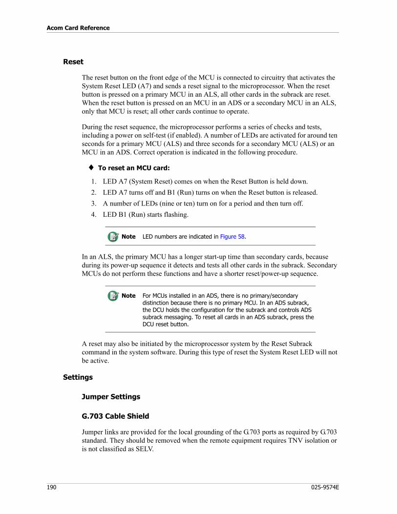
Acom Card Reference
190 025-9574E
Reset
The reset button on the front edge of the MCU is connected to circuitry that activates the System Reset LED (A7) and sends a reset signal to the microprocessor. When the reset button is pressed on a primary MCU in an ALS, all other cards in the subrack are reset. When the reset button is pressed on an MCU in an ADS or a secondary MCU in an ALS, only that MCU is reset; all other cards continue to operate.
During the reset sequence, the microprocessor performs a series of checks and tests, including a power on self-test (if enabled). A number of LEDs are activated for around ten seconds for a primary MCU (ALS) and three seconds for a secondary MCU (ALS) or an MCU in an ADS. Correct operation is indicated in the following procedure.
♦ To reset an MCU card:
1. LED A7 (System Reset) comes on when the Reset Button is held down.2. LED A7 turns off and B1 (Run) turns on when the Reset button is released.3. A number of LEDs (nine or ten) turn on for a period and then turn off.4. LED B1 (Run) starts flashing.
In an ALS, the primary MCU has a longer start-up time than secondary cards, because during its power-up sequence it detects and tests all other cards in the subrack. Secondary MCUs do not perform these functions and have a shorter reset/power-up sequence.
A reset may also be initiated by the microprocessor system by the Reset Subrack command in the system software. During this type of reset the System Reset LED will not be active.
Settings
Jumper Settings
G.703 Cable Shield
Jumper links are provided for the local grounding of the G.703 ports as required by G.703 standard. They should be removed when the remote equipment requires TNV isolation or is not classified as SELV.
Note LED numbers are indicated in Figure 58.
Note For MCUs installed in an ADS, there is no primary/secondary distinction because there is no primary MCU. In an ADS subrack, the DCU holds the configuration for the subrack and controls ADS subrack messaging. To reset all cards in an ADS subrack, press the DCU reset button.
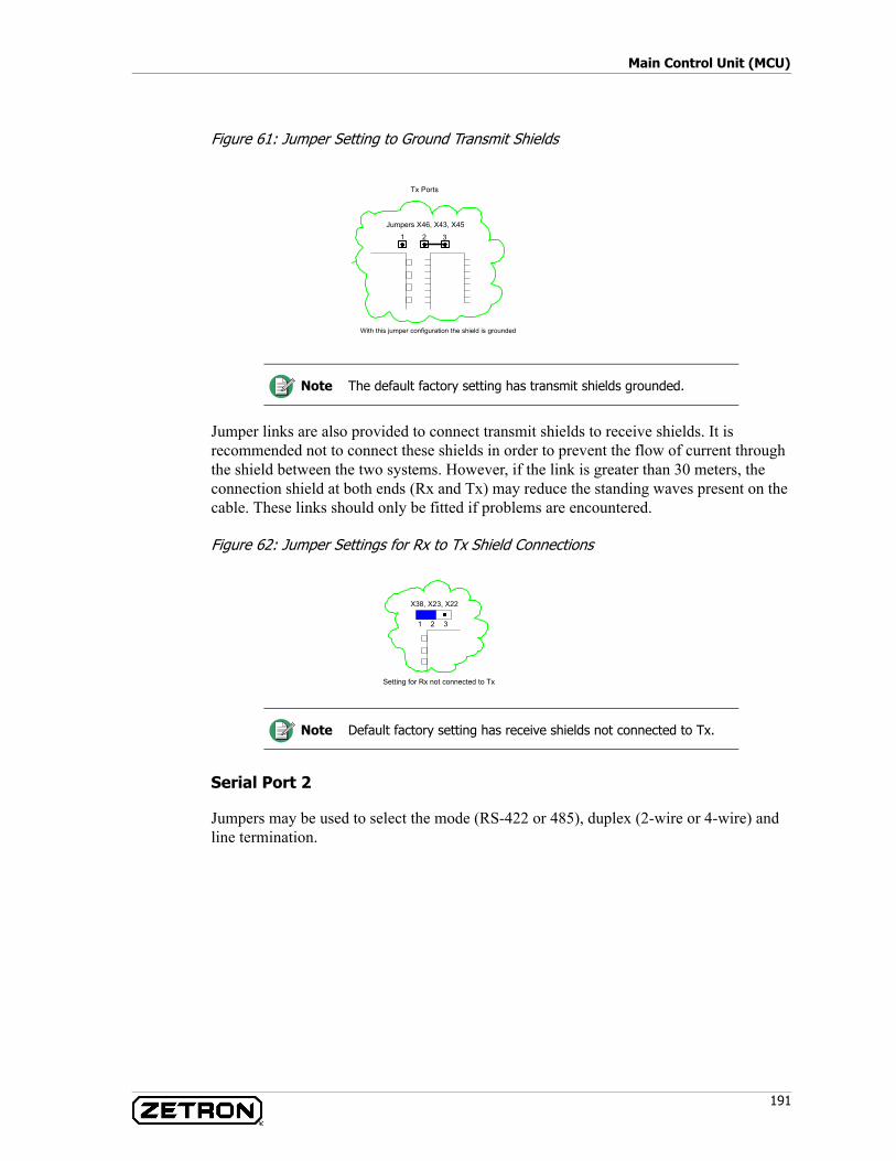
191
Main Control Unit (MCU)
Figure 61: Jumper Setting to Ground Transmit Shields
Jumper links are also provided to connect transmit shields to receive shields. It is recommended not to connect these shields in order to prevent the flow of current through the shield between the two systems. However, if the link is greater than 30 meters, the connection shield at both ends (Rx and Tx) may reduce the standing waves present on the cable. These links should only be fitted if problems are encountered.
Figure 62: Jumper Settings for Rx to Tx Shield Connections
Serial Port 2
Jumpers may be used to select the mode (RS-422 or 485), duplex (2-wire or 4-wire) and line termination.
Note The default factory setting has transmit shields grounded.
Note Default factory setting has receive shields not connected to Tx.
Tx Ports
With this jumper configuration the shield is grounded
Jumpers X46, X43, X45
1 2 3
Setting for Rx not connected to Tx
1 2 3
X38, X23, X22
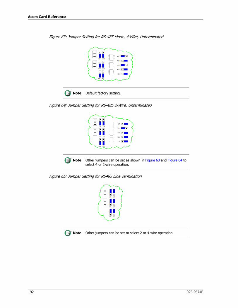
Acom Card Reference
192 025-9574E
Figure 63: Jumper Setting for RS-485 Mode, 4-Wire, Unterminated
Figure 64: Jumper Setting for RS-485 2-Wire, Unterminated
Figure 65: Jumper Setting for RS485 Line Termination
Note Default factory setting.
Note Other jumpers can be set as shown in Figure 63 and Figure 64 to select 4 or 2-wire operation.
Note Other jumpers can be set to select 2 or 4-wire operation.
x24 x28
x20 x21
x29 x37
x27
X25
X30
X26
X36
x24 x28
x20 x21
x29 x37
x27
X25
X30
X26
X36
x24 x28
x20 x21
x29 x37
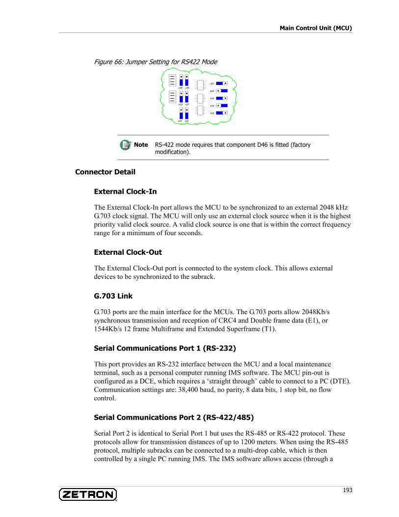
193
Main Control Unit (MCU)
Figure 66: Jumper Setting for RS422 Mode
Connector Detail
External Clock-In
The External Clock-In port allows the MCU to be synchronized to an external 2048 kHz G.703 clock signal. The MCU will only use an external clock source when it is the highest priority valid clock source. A valid clock source is one that is within the correct frequency range for a minimum of four seconds.
External Clock-Out
The External Clock-Out port is connected to the system clock. This allows external devices to be synchronized to the subrack.
G.703 Link
G.703 ports are the main interface for the MCUs. The G.703 ports allow 2048Kb/s synchronous transmission and reception of CRC4 and Double frame data (E1), or 1544Kb/s 12 frame Multiframe and Extended Superframe (T1).
Serial Communications Port 1 (RS-232)
This port provides an RS-232 interface between the MCU and a local maintenance terminal, such as a personal computer running IMS software. The MCU pin-out is configured as a DCE, which requires a ‘straight through’ cable to connect to a PC (DTE). Communication settings are: 38,400 baud, no parity, 8 data bits, 1 stop bit, no flow control.
Serial Communications Port 2 (RS-422/485)
Serial Port 2 is identical to Serial Port 1 but uses the RS-485 or RS-422 protocol. These protocols allow for transmission distances of up to 1200 meters. When using the RS-485 protocol, multiple subracks can be connected to a multi-drop cable, which is then controlled by a single PC running IMS. The IMS software allows access (through a
Note RS-422 mode requires that component D46 is fitted (factory modification).
x24 x28
x20 x21
x29 x37
x27
X25
X30
X26
X36
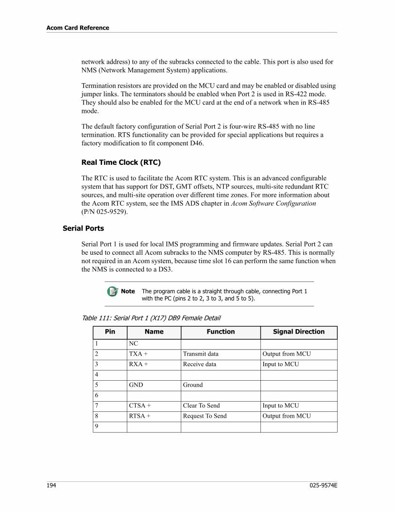
Acom Card Reference
194 025-9574E
network address) to any of the subracks connected to the cable. This port is also used for NMS (Network Management System) applications.
Termination resistors are provided on the MCU card and may be enabled or disabled using jumper links. The terminators should be enabled when Port 2 is used in RS-422 mode. They should also be enabled for the MCU card at the end of a network when in RS-485 mode.
The default factory configuration of Serial Port 2 is four-wire RS-485 with no line termination. RTS functionality can be provided for special applications but requires a factory modification to fit component D46.
Real Time Clock (RTC)
The RTC is used to facilitate the Acom RTC system. This is an advanced configurable system that has support for DST, GMT offsets, NTP sources, multi-site redundant RTC sources, and multi-site operation over different time zones. For more information about the Acom RTC system, see the IMS ADS chapter in Acom Software Configuration (P/N 025-9529).
Serial Ports
Serial Port 1 is used for local IMS programming and firmware updates. Serial Port 2 can be used to connect all Acom subracks to the NMS computer by RS-485. This is normally not required in an Acom system, because time slot 16 can perform the same function when the NMS is connected to a DS3.
Table 111: Serial Port 1 (X17) DB9 Female Detail
Note The program cable is a straight through cable, connecting Port 1 with the PC (pins 2 to 2, 3 to 3, and 5 to 5).
Pin Name Function Signal Direction
1 NC2 TXA + Transmit data Output from MCU3 RXA + Receive data Input to MCU45 GND Ground67 CTSA + Clear To Send Input to MCU8 RTSA + Request To Send Output from MCU9
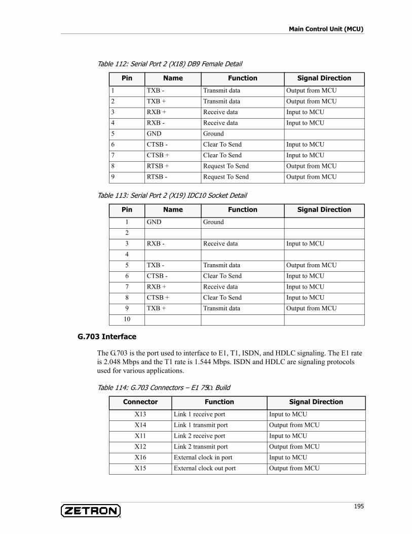
195
Main Control Unit (MCU)
Table 112: Serial Port 2 (X18) DB9 Female Detail
Table 113: Serial Port 2 (X19) IDC10 Socket Detail
G.703 Interface
The G.703 is the port used to interface to E1, T1, ISDN, and HDLC signaling. The E1 rate is 2.048 Mbps and the T1 rate is 1.544 Mbps. ISDN and HDLC are signaling protocols used for various applications.
Table 114: G.703 Connectors – E1 75Ω Build
Pin Name Function Signal Direction
1 TXB - Transmit data Output from MCU2 TXB + Transmit data Output from MCU3 RXB + Receive data Input to MCU4 RXB - Receive data Input to MCU5 GND Ground6 CTSB - Clear To Send Input to MCU7 CTSB + Clear To Send Input to MCU8 RTSB + Request To Send Output from MCU9 RTSB - Request To Send Output from MCU
Pin Name Function Signal Direction
1 GND Ground23 RXB - Receive data Input to MCU45 TXB - Transmit data Output from MCU6 CTSB - Clear To Send Input to MCU7 RXB + Receive data Input to MCU8 CTSB + Clear To Send Input to MCU9 TXB + Transmit data Output from MCU
10
Connector Function Signal Direction
X13 Link 1 receive port Input to MCUX14 Link 1 transmit port Output from MCUX11 Link 2 receive port Input to MCUX12 Link 2 transmit port Output from MCUX16 External clock in port Input to MCUX15 External clock out port Output from MCU
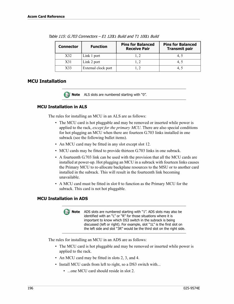
Acom Card Reference
196 025-9574E
Table 115: G.703 Connectors – E1 120Ω Build and T1 100Ω Build
MCU Installation
MCU Installation in ALS
The rules for installing an MCU in an ALS are as follows:• The MCU card is hot pluggable and may be removed or inserted while power is
applied to the rack, except for the primary MCU. There are also special conditions for hot plugging an MCU when there are fourteen G.703 links installed in one subrack (see the following bullet items).
• An MCU card may be fitted in any slot except slot 12.• MCU cards may be fitted to provide thirteen G.703 links in one subrack.• A fourteenth G.703 link can be used with the provision that all the MCU cards are
installed at power-up. Hot plugging an MCU in a subrack with fourteen links causes the Primary MCU to re-allocate backplane resources to the MSU or to another card installed in the subrack. This will result in the fourteenth link becoming unavailable.
• A MCU card must be fitted in slot 0 to function as the Primary MCU for the subrack. This card is not hot pluggable.
MCU Installation in ADS
The rules for installing an MCU in an ADS are as follows:• The MCU card is hot pluggable and may be removed or inserted while power is
applied to the rack.• An MCU card may be fitted in slots 2, 3, and 4.• Install MCU cards from left to right, so a DS3 switch with...
• ...one MCU card should reside in slot 2.
Connector Function Pins for Balanced Receive Pair
Pins for Balanced Transmit pair
X32 Link 1 port 1, 2 4, 5X31 Link 2 port 1, 2 4, 5X33 External clock port 1, 2 4, 5
Note ALS slots are numbered starting with “0”.
Note ADS slots are numbered starting with “1”. ADS slots may also be identified with an “L” or “R” for those situations where it is important to know which DS3 switch in the subrack is being discussed (left or right). For example, slot “1L” is the first slot on the left side and slot “3R” would be the third slot on the right side.
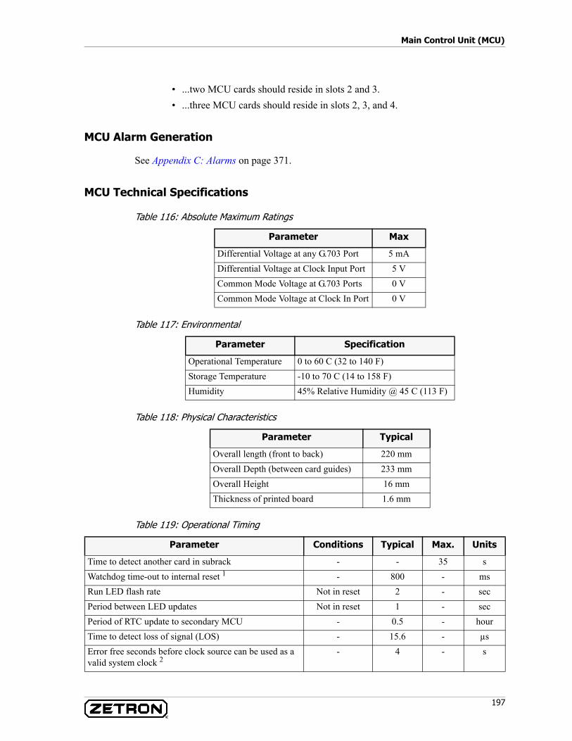
197
Main Control Unit (MCU)
• ...two MCU cards should reside in slots 2 and 3.• ...three MCU cards should reside in slots 2, 3, and 4.
MCU Alarm Generation
See Appendix C: Alarms on page 371.
MCU Technical Specifications
Table 116: Absolute Maximum Ratings
Table 117: Environmental
Table 118: Physical Characteristics
Table 119: Operational Timing
Parameter Max
Differential Voltage at any G.703 Port 5 mADifferential Voltage at Clock Input Port 5 VCommon Mode Voltage at G.703 Ports 0 VCommon Mode Voltage at Clock In Port 0 V
Parameter Specification
Operational Temperature 0 to 60 C (32 to 140 F)Storage Temperature -10 to 70 C (14 to 158 F)Humidity 45% Relative Humidity @ 45 C (113 F)
Parameter Typical
Overall length (front to back) 220 mmOverall Depth (between card guides) 233 mmOverall Height 16 mmThickness of printed board 1.6 mm
Parameter Conditions Typical Max. Units
Time to detect another card in subrack - - 35 sWatchdog time-out to internal reset 1 - 800 - msRun LED flash rate Not in reset 2 - secPeriod between LED updates Not in reset 1 - secPeriod of RTC update to secondary MCU - 0.5 - hourTime to detect loss of signal (LOS) - 15.6 - µsError free seconds before clock source can be used as a valid system clock 2
- 4 - s

Acom Card Reference
198 025-9574E
1.The operation of the Watchdog Timer causes an internal reset only and does not cause the MCU Reset LED to operate.
2.Clock sources may include recovered or external clocks.
1544 Kbps Data Processing
Main Interface Data Rate: 1544 kbps ± 50 ppmFrame Format: Selectable 12 Frame Multi-Frame or Extended
SuperFrameFrame Rate: 8000 frames/secondFrames per Multi-frame: 12 or 24Time slots per Frame: 24Bits per Time Slot: 8Multiplex Principle: Time Slot Interleaving
2048 Kbps Data Processing
Main Interface Data Rate: 2048 kbps ± 50 ppmFrame Format: Selectable Double-Frame or CRC Multi-frameFrame Rate: 8000 frames/secondFrames per Multi-frame: 16Time Slots per Frame: 32Bits per Time Slot: 8Multiplex Principle: Time Slot Interleaving
2048 kbps Digital Interface – 75Ω G.703/G.823
Physical Connection: Coaxial, type SMB (RG179 Coax)Line Code: HDB3Line Impedance: 75Ω (unbalanced)
Table 120: 75Ω Digital Interface - Electrical Characteristics
Error free seconds before Link alarms are deactivated. - 4 - s
Parameter Conditions Typical Max. Units
Parameter Conditions Min. Typical Max Units
Bit Rate - 2047897 2048000 2048102 HzPeak voltage of a mark (pulse) - 2.13 2.37 2.61 VPeak voltage of a space (no pulse) - -0.237 0 0.237 VNominal pulse width - - 244 - nsIntrinsic Jitter 20 –1E5 Hz - - 0.015 UI p-pReceiver Differential Input Threshold - - 1.04 - VReturn Loss 102-2048 Hz 18 - - dBInput Signal Attenuation No equalizing. - 6 - dB
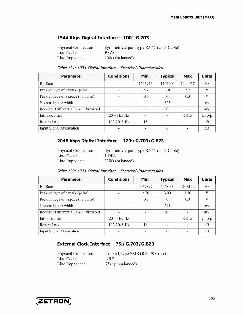
199
Main Control Unit (MCU)
1544 Kbps Digital Interface – 100Ω G.703
Physical Connection: Symmetrical pair, type RJ-45 (UTP Cable)Line Code: B8ZSLine Impedance: 100Ω (balanced)
Table 121: 100Ω Digital Interface – Electrical Characteristics
2048 kbps Digital Interface – 120Ω G.703/G.823
Physical Connection: Symmetrical pair, type RJ-45 (UTP Cable)Line Code: HDB3Line Impedance: 120Ω (balanced)
Table 122: 120Ω Digital Interface – Electrical Characteristics
External Clock Interface – 75Ω G.703/G.823
Physical Connection: Coaxial, type SMB (RG179 Coax)Line Code: NRZLine Impedance: 75Ω (unbalanced)
Parameter Conditions Min. Typical Max Units
Bit Rate - 1543923 1544000 1544077 HzPeak voltage of a mark (pulse) - 2.3 3.0 3.7 VPeak voltage of a space (no pulse) - -0.3 0 0.3 VNominal pulse width - - 323 - nsReceiver Differential Input Threshold - - 200 - mVIntrinsic Jitter 20 – 1E5 Hz - - 0.015 UI p-pReturn Loss 102-2048 Hz 18 - - dBInput Signal Attenuation - - 6 - dB
Parameter Conditions Min. Typical Max Units
Bit Rate - 2047897 2048000 2048102 HzPeak voltage of a mark (pulse) - 2.70 3.00 3.30 VPeak voltage of a space (no pulse) - -0.3 0 0.3 VNominal pulse width - - 244 - nsReceiver Differential Input Threshold - - 200 - mVIntrinsic Jitter 20 – 1E5 Hz - - 0.015 UI p-pReturn Loss 102-2048 Hz 18 - - dBInput Signal Attenuation - - 6 - dB

Acom Card Reference
200 025-9574E
Table 123: 75Ω Clock Interface - Electrical Characteristics
External Clock Interface – 100Ω G.703
Physical Connection: Symmetrical pair, type RJ-45 (UTP Cable)Line Code: NRZLine Impedance: 100Ω (balanced)
Table 124: 100Ω Clock Interface - Electrical Characteristics
External Clock Interface – 120Ω G.703/G.823
Physical Connection: Symmetrical pair, type RJ-45 (UTP Cable)Line Code: NRZLine Impedance: 120Ω (balanced)
Table 125: 120Ω Clock Interface – Electrical Characteristics
Maintenance Terminal Interface RS-232
Physical Connection: DB9 FemalePhysical Interface: RS-232C / V24Line Settings: 38400, N, 8, 1
Table 126: Maintenance Terminal Interface – Electrical Characteristics
Parameter Conditions Min. Typical Max Units
Clock Out Port Frequency - 2047897 2048000 2048102 HzClock In Port Frequency - 2047693 2048000 2048307 HzClock Signal Peak Voltage - 0.75 1.0 1.5 VClock Signal Nominal Pulse Width - - 244 - ns
Parameter Conditions Min. Typical Max Units
Bit Rate - 1543923 1544000 1544077 HzPeak Voltage - 1.0 1.5 1.9 VNominal Pulse Width - - 323 - ns
Parameter Conditions Min. Typical Max Units
Bit Rate - 2047897 2048000 2048102 HzPeak Voltage - 1.0 1.5 1.9 VNominal Pulse Width - - 244 - ns
Parameter Conditions Min. Typical Max Units
Data Rate - - 38400 - bpsTransmitter Output Voltage Swing 3 kΩ Load ±5 ±9 - V
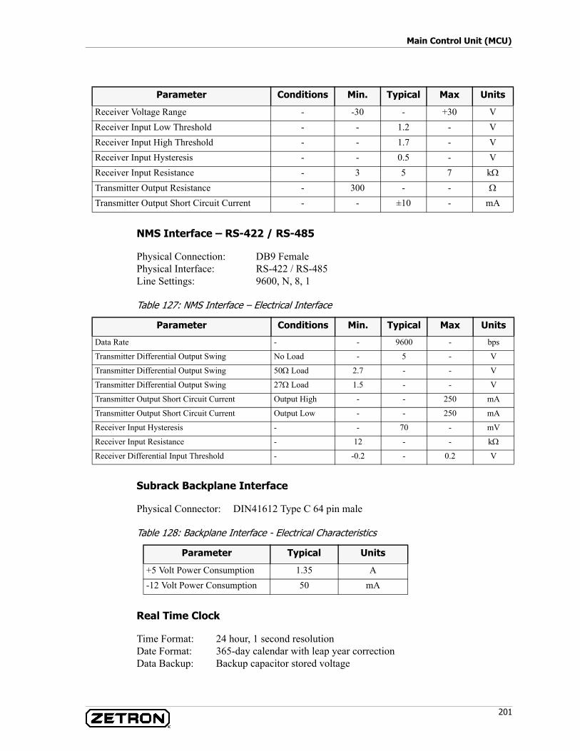
201
Main Control Unit (MCU)
NMS Interface – RS-422 / RS-485
Physical Connection: DB9 FemalePhysical Interface: RS-422 / RS-485Line Settings: 9600, N, 8, 1
Table 127: NMS Interface – Electrical Interface
Subrack Backplane Interface
Physical Connector: DIN41612 Type C 64 pin male
Table 128: Backplane Interface - Electrical Characteristics
Real Time Clock
Time Format: 24 hour, 1 second resolutionDate Format: 365-day calendar with leap year correctionData Backup: Backup capacitor stored voltage
Receiver Voltage Range - -30 - +30 VReceiver Input Low Threshold - - 1.2 - VReceiver Input High Threshold - - 1.7 - VReceiver Input Hysteresis - - 0.5 - VReceiver Input Resistance - 3 5 7 kΩ
Transmitter Output Resistance - 300 - - Ω
Transmitter Output Short Circuit Current - - ±10 - mA
Parameter Conditions Min. Typical Max Units
Parameter Conditions Min. Typical Max Units
Data Rate - - 9600 - bps
Transmitter Differential Output Swing No Load - 5 - V
Transmitter Differential Output Swing 50Ω Load 2.7 - - V
Transmitter Differential Output Swing 27Ω Load 1.5 - - V
Transmitter Output Short Circuit Current Output High - - 250 mA
Transmitter Output Short Circuit Current Output Low - - 250 mA
Receiver Input Hysteresis - - 70 - mV
Receiver Input Resistance - 12 - - kΩ
Receiver Differential Input Threshold - -0.2 - 0.2 V
Parameter Typical Units
+5 Volt Power Consumption 1.35 A-12 Volt Power Consumption 50 mA

Acom Card Reference
202 025-9574E
Backup Duration
The card can hold time without power for up to three days.
Electromagnetic Compatibility
Compliant to AS3548, Class A and FCC Part 15, Class A.
Main Supply Unit (MSU)
P/N 950-0487
The MSU provides DC-DC conversion that powers the Acom subrack or ADS rack from a battery or rectifier ‘station supply.’ The input voltage must be in the -20 to -60 VDC range. The MSU generates the +5, +12, and –12 volt power rails required by the plug-in cards as well as an isolated –12 volt supply used for TNV circuitry. The MSU also handles system alarms and provides a general purpose 4-wire audio interface. (See MSU Options in Acom Software Installation and Configuration, P/N 025-9529.)
The MSU card has the following features:• DC-DC conversion• Redundant / Load sharing operation• Automatic shutdown on failure• LEDs and relays for three G.732 composite general system alarms• Six general-purpose alarm inputs• Six alarm outputs, one fixed and five programmable general-purpose• A general-purpose 4-wire audio interface intended for use as an engineering order
wire (EOW) system, voice recorder output, or as a test port• Tone generation
MSU Block Diagram
Figure 67 shows the major functional blocks in the MSU. Table 129 describes these functional blocks in detail.
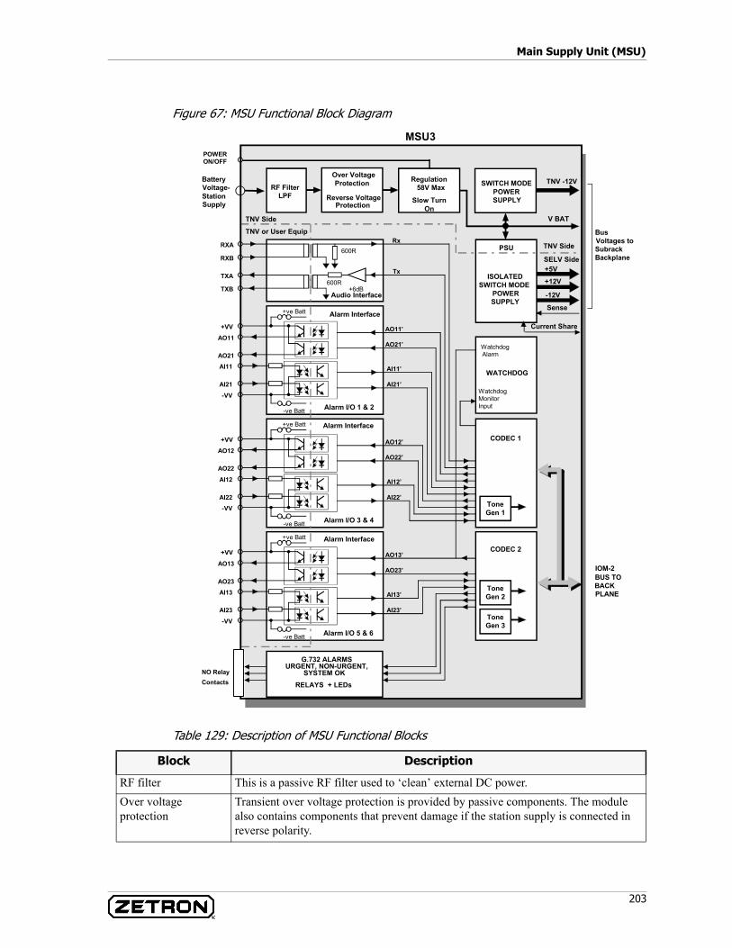
203
Main Supply Unit (MSU)
Figure 67: MSU Functional Block Diagram
Table 129: Description of MSU Functional Blocks
+5V
+12V
-12V
V BAT
TNV -12VSWITCH MODEPOWERSUPPLY
ISOLATEDSWITCH MODE
POWERSUPPLY
PSU TNV Side
SELV Side
RXA Rx
MSU3
RXB
Audio Interface
600R
TXA
TXB600R
+6dB
Tx
Regulation58V Max
Slow TurnOn
Over VoltageProtection
Reverse VoltageProtection
RF FilterLPF
WATCHDOG
TNV Side
TNV or User Equip
BatteryVoltage-StationSupply
+VV
AO11
AO21
-VV
AI21
AI11
Alarm Interface
AO11’
AO21’
AI11’
AI21’
Alarm I/O 1 & 2
+ve Batt
-ve Batt
CODEC 1+VV
AO12
AO22
-VVAI22
AI12
Alarm Interface
AO12’
AO22’
AI12’
AI22’
Alarm I/O 3 & 4
+ve Batt
-ve Batt
WatchdogMonitorInput
WatchdogAlarm
POWERON/OFF
CODEC 2+VV
AO13
AO23
NO Relay
-VV
AI23
AI13
Alarm Interface
AO13’
AO23’
AI13’
AI23’
Alarm I/O 5 & 6
+ve Batt
-ve Batt
IOM-2BUS TOBACKPLANE
BusVoltages toSubrackBackplane
ToneGen 3
ToneGen 2
ToneGen 1
G.732 ALARMSURGENT, NON-URGENT,
SYSTEM OK
Sense
Current Share
RELAYS + LEDsContacts
Block Description
RF filter This is a passive RF filter used to ‘clean’ external DC power.Over voltage protection
Transient over voltage protection is provided by passive components. The module also contains components that prevent damage if the station supply is connected in reverse polarity.
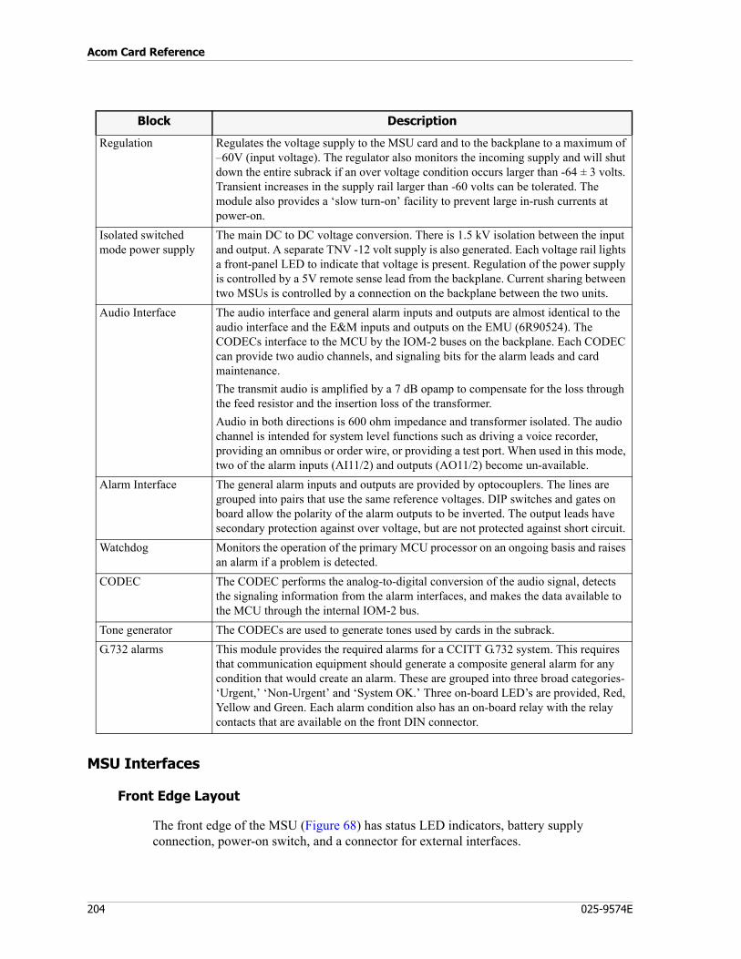
Acom Card Reference
204 025-9574E
MSU Interfaces
Front Edge Layout
The front edge of the MSU (Figure 68) has status LED indicators, battery supply connection, power-on switch, and a connector for external interfaces.
Regulation Regulates the voltage supply to the MSU card and to the backplane to a maximum of –60V (input voltage). The regulator also monitors the incoming supply and will shut down the entire subrack if an over voltage condition occurs larger than -64 ± 3 volts. Transient increases in the supply rail larger than -60 volts can be tolerated. The module also provides a ‘slow turn-on’ facility to prevent large in-rush currents at power-on.
Isolated switched mode power supply
The main DC to DC voltage conversion. There is 1.5 kV isolation between the input and output. A separate TNV -12 volt supply is also generated. Each voltage rail lights a front-panel LED to indicate that voltage is present. Regulation of the power supply is controlled by a 5V remote sense lead from the backplane. Current sharing between two MSUs is controlled by a connection on the backplane between the two units.
Audio Interface The audio interface and general alarm inputs and outputs are almost identical to the audio interface and the E&M inputs and outputs on the EMU (6R90524). The CODECs interface to the MCU by the IOM-2 buses on the backplane. Each CODEC can provide two audio channels, and signaling bits for the alarm leads and card maintenance.The transmit audio is amplified by a 7 dB opamp to compensate for the loss through the feed resistor and the insertion loss of the transformer.Audio in both directions is 600 ohm impedance and transformer isolated. The audio channel is intended for system level functions such as driving a voice recorder, providing an omnibus or order wire, or providing a test port. When used in this mode, two of the alarm inputs (AI11/2) and outputs (AO11/2) become un-available.
Alarm Interface The general alarm inputs and outputs are provided by optocouplers. The lines are grouped into pairs that use the same reference voltages. DIP switches and gates on board allow the polarity of the alarm outputs to be inverted. The output leads have secondary protection against over voltage, but are not protected against short circuit.
Watchdog Monitors the operation of the primary MCU processor on an ongoing basis and raises an alarm if a problem is detected.
CODEC The CODEC performs the analog-to-digital conversion of the audio signal, detects the signaling information from the alarm interfaces, and makes the data available to the MCU through the internal IOM-2 bus.
Tone generator The CODECs are used to generate tones used by cards in the subrack.G.732 alarms This module provides the required alarms for a CCITT G.732 system. This requires
that communication equipment should generate a composite general alarm for any condition that would create an alarm. These are grouped into three broad categories- ‘Urgent,’ ‘Non-Urgent’ and ‘System OK.’ Three on-board LED’s are provided, Red, Yellow and Green. Each alarm condition also has an on-board relay with the relay contacts that are available on the front DIN connector.
Block Description
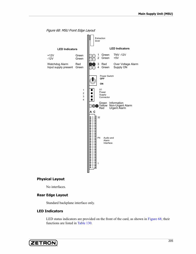
205
Main Supply Unit (MSU)
Figure 68: MSU Front Edge Layout
Physical Layout
No interfaces.
Rear Edge Layout
Standard backplane interface only.
LED Indicators
LED status indicators are provided on the front of the card, as shown in Figure 68; their functions are listed in Table 130.
X1PowerSupplyConnector
LED Indicators
1 Green TNV -12V2 Green +5V
Extractionlever
LED Indicators
+12V Green-12V Green
A C
32
P4 Audio andAlarmInterface
1
3 Red Over Voltage Alarm4 Green Supply ON
Watchdog Alarm RedInput supply present Green
Green InformationYellow Non-Urgent AlarmRed Urgent Alarm
Power SwitchOFF
ON
21
43
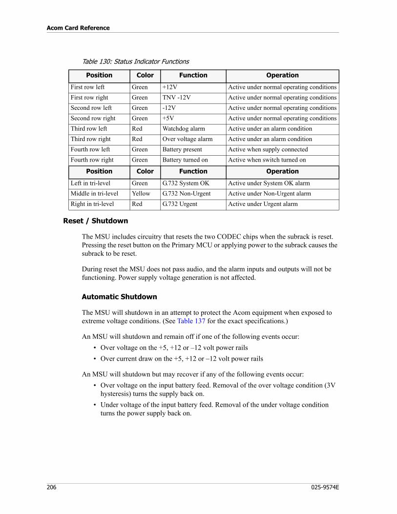
Acom Card Reference
206 025-9574E
Table 130: Status Indicator Functions
Reset / Shutdown
The MSU includes circuitry that resets the two CODEC chips when the subrack is reset. Pressing the reset button on the Primary MCU or applying power to the subrack causes the subrack to be reset.
During reset the MSU does not pass audio, and the alarm inputs and outputs will not be functioning. Power supply voltage generation is not affected.
Automatic Shutdown
The MSU will shutdown in an attempt to protect the Acom equipment when exposed to extreme voltage conditions. (See Table 137 for the exact specifications.)
An MSU will shutdown and remain off if one of the following events occur:• Over voltage on the +5, +12 or –12 volt power rails• Over current draw on the +5, +12 or –12 volt power rails
An MSU will shutdown but may recover if any of the following events occur:• Over voltage on the input battery feed. Removal of the over voltage condition (3V
hysteresis) turns the supply back on.• Under voltage of the input battery feed. Removal of the under voltage condition
turns the power supply back on.
Position Color Function Operation
First row left Green +12V Active under normal operating conditionsFirst row right Green TNV -12V Active under normal operating conditionsSecond row left Green -12V Active under normal operating conditionsSecond row right Green +5V Active under normal operating conditionsThird row left Red Watchdog alarm Active under an alarm conditionThird row right Red Over voltage alarm Active under an alarm conditionFourth row left Green Battery present Active when supply connectedFourth row right Green Battery turned on Active when switch turned on
Position Color Function Operation
Left in tri-level Green G.732 System OK Active under System OK alarmMiddle in tri-level Yellow G.732 Non-Urgent Active under Non-Urgent alarmRight in tri-level Red G.732 Urgent Active under Urgent alarm
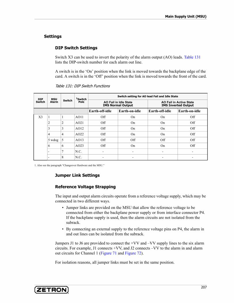
207
Main Supply Unit (MSU)
Settings
DIP Switch Settings
Switch X3 can be used to invert the polarity of the alarm output (AO) leads. Table 131 lists the DIP-switch number for each alarm out line.
A switch is in the ‘On’ position when the link is moved towards the backplane edge of the card. A switch is in the ‘Off’ position when the link is moved towards the front of the card.
Table 131: DIP Switch Functions
1. Also see the paragraph “Changeover Hardware and the MSU.”
Jumper Link Settings
Reference Voltage Strapping
The input and output alarm circuits operate from a reference voltage supply, which may be connected in two different ways.
• Jumper links are provided on the MSU that allow the reference voltage to be connected from either the backplane power supply or from interface connector P4. If the backplane supply is used, then the alarm circuits are not isolated from the subrack.
• By connecting an external supply to the reference voltage pins on P4, the alarm in and out lines can be isolated from the subrack.
Jumpers J1 to J6 are provided to connect the +VV and –VV supply lines to the six alarm circuits. For example, J1 connects +VV, and J2 connects –VV to the alarm in and alarm out circuits for Channel 1 (Figure 71 and Figure 72).
For isolation reasons, all jumper links must be set in the same position.
DIP Switch
MSU Alarm Switch
1Switch Pole
Switch setting for AO lead Fail and Idle State
AO Fail in Idle StateIMS Normal Output
AO Fail in Active StateIMS Inverted Output
Earth-off-idle Earth-on-idle Earth-off-idle Earth-on-idleX3 1 1 AO11 Off On On Off
2 2 AO21 Off On On Off
3 3 AO12 Off On On Off
4 4 AO22 Off On On Off
5 wdog 5 AO13 Off Off Off Off
6 6 AO23 Off On On Off
- 7 N.C. - - - -
- 8 N.C. - - - -
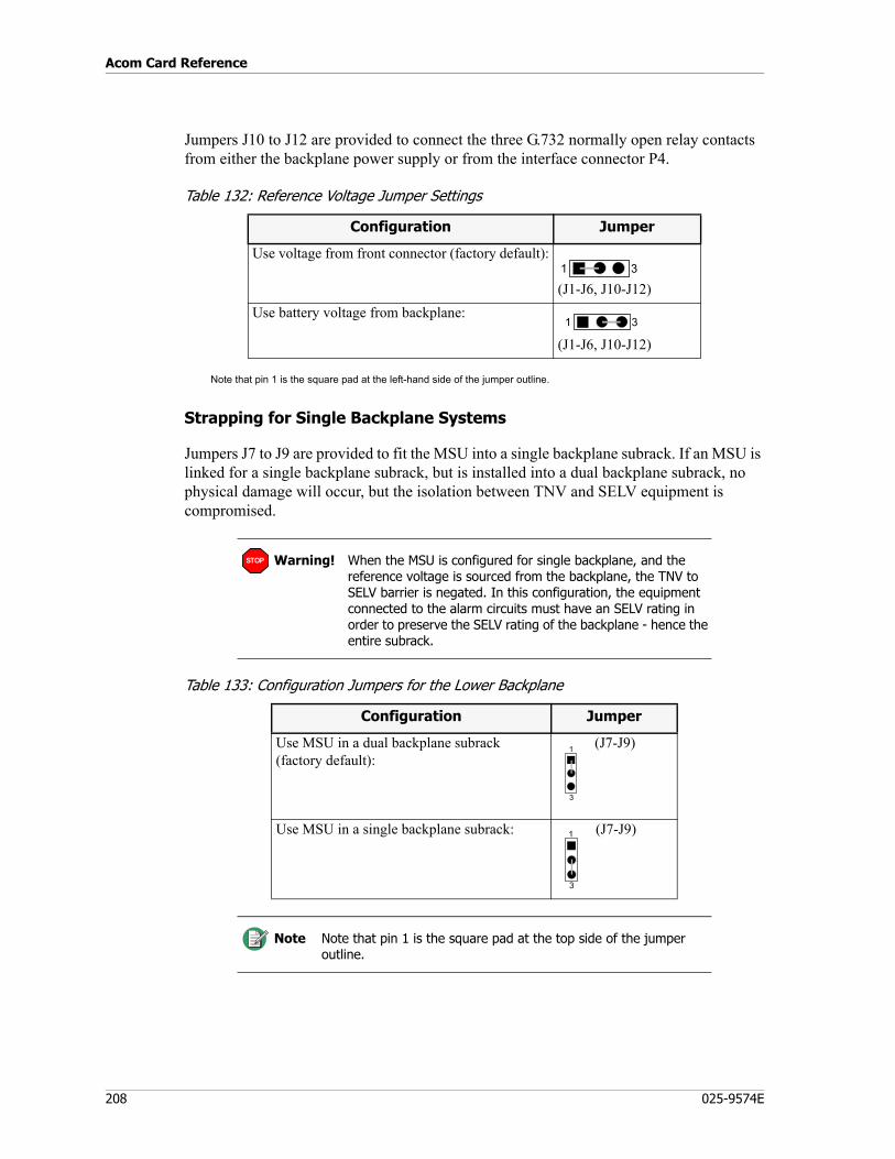
Acom Card Reference
208 025-9574E
Jumpers J10 to J12 are provided to connect the three G.732 normally open relay contacts from either the backplane power supply or from the interface connector P4.
Table 132: Reference Voltage Jumper Settings
Note that pin 1 is the square pad at the left-hand side of the jumper outline.
Strapping for Single Backplane Systems
Jumpers J7 to J9 are provided to fit the MSU into a single backplane subrack. If an MSU is linked for a single backplane subrack, but is installed into a dual backplane subrack, no physical damage will occur, but the isolation between TNV and SELV equipment is compromised.
Table 133: Configuration Jumpers for the Lower Backplane
Configuration Jumper
Use voltage from front connector (factory default):
(J1-J6, J10-J12)Use battery voltage from backplane:
(J1-J6, J10-J12)
1 3
1 3
Warning! When the MSU is configured for single backplane, and the reference voltage is sourced from the backplane, the TNV to SELV barrier is negated. In this configuration, the equipment connected to the alarm circuits must have an SELV rating in order to preserve the SELV rating of the backplane - hence the entire subrack.
Configuration Jumper
Use MSU in a dual backplane subrack (factory default):
(J7-J9)
Use MSU in a single backplane subrack: (J7-J9)
Note Note that pin 1 is the square pad at the top side of the jumper outline.
STOP
1
3
1
3
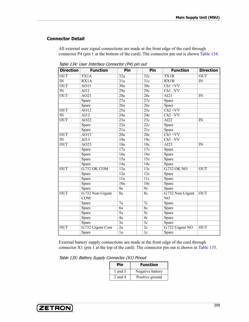
209
Main Supply Unit (MSU)
Connector Detail
All external user signal connections are made at the front edge of the card through connector P4 (pin 1 at the bottom of the card). The connector pin out is shown Table 134.
Table 134: User Interface Connector (P4) pin out
External battery supply connections are made at the front edge of the card through connector X1 (pin 1 at the top of the card). The connector pin out is shown in Table 135.
Table 135: Battery Supply Connector (X1) Pinout
Direction Function Pin Pin Function DirectionOUT TX1A 32a 32c TX1B OUTIN RX1A 31a 31c RX1B INOUT AO11 30a 30c Ch1 +VVIN AI11 29a 29c Ch1 –VVOUT AO21 28a 28c AI21 IN
Spare 27a 27c SpareSpare 26a 26c Spare
OUT AO12 25a 25c Ch2 +VVIN AI12 24a 24c Ch2 –VVOUT AO22 23a 23c AI22 IN
Spare 22a 22c SpareSpare 21a 21c Spare
OUT AO13 20a 20c Ch3 +VVIN AI13 19a 19c Ch3 –VVOUT AO23 18a 18c AI23 IN
Spare 17a 17c SpareSpare 16a 16c SpareSpare 15a 15c SpareSpare 14a 14c Spare
OUT G.732 OK COM 13a 13c G.732 OK NO OUTSpare 12a 12c SpareSpare 11a 11c SpareSpare 10a 10c SpareSpare 9a 9c Spare
OUT G.732 Non-Urgent COM
8a 8c G.732 Non-Urgent NO
OUT
Spare 7a 7c SpareSpare 6a 6c SpareSpare 5a 5c SpareSpare 4a 4c SpareSpare 3a 3c Spare
OUT G.732 Urgent Com 2a 2c G.732 Urgent NO OUTSpare 1a 1c Spare
Pin Function
1 and 3 Negative battery2 and 4 Positive ground
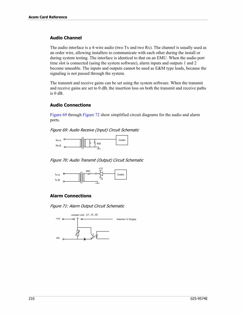
Acom Card Reference
210 025-9574E
Audio Channel
The audio interface is a 4-wire audio (two Tx and two Rx). The channel is usually used as an order wire, allowing installers to communicate with each other during the install or during system testing. The interface is identical to that on an EMU. When the audio port time slot is connected (using the system software), alarm inputs and outputs 1 and 2 become unusable. The inputs and outputs cannot be used as E&M type leads, because the signaling is not passed through the system.
The transmit and receive gains can be set using the system software. When the transmit and receive gains are set to 0 dB, the insertion loss on both the transmit and receive paths is 0 dB.
Audio Connections
Figure 69 through Figure 72 show simplified circuit diagrams for the audio and alarm ports.
Figure 69: Audio Receive (Input) Circuit Schematic
Figure 70: Audio Transmit (Output) Circuit Schematic
Alarm Connections
Figure 71: Alarm Output Circuit Schematic
Rx A
Rx B600
Codec
+12
Tx A
Tx B
600Codec
-12
+VV
AO
Jumper Link
Internal +V Supply
(J1, J3, J5)
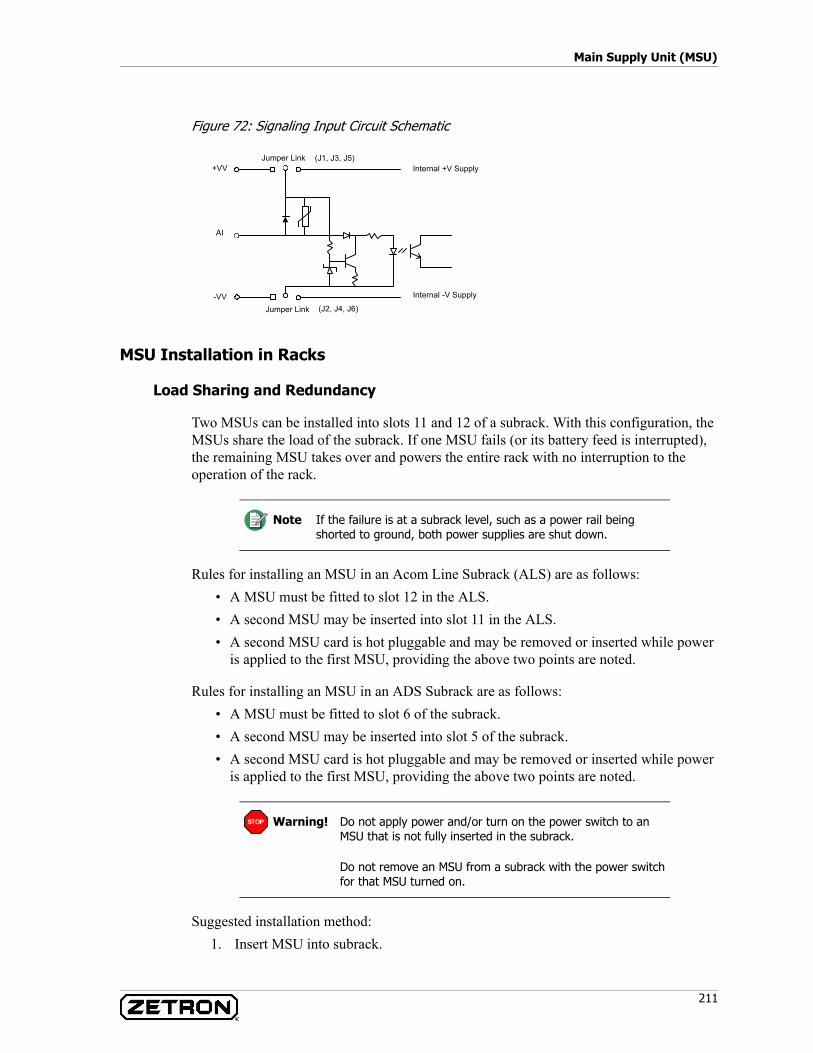
211
Main Supply Unit (MSU)
Figure 72: Signaling Input Circuit Schematic
MSU Installation in Racks
Load Sharing and Redundancy
Two MSUs can be installed into slots 11 and 12 of a subrack. With this configuration, the MSUs share the load of the subrack. If one MSU fails (or its battery feed is interrupted), the remaining MSU takes over and powers the entire rack with no interruption to the operation of the rack.
Rules for installing an MSU in an Acom Line Subrack (ALS) are as follows:• A MSU must be fitted to slot 12 in the ALS.• A second MSU may be inserted into slot 11 in the ALS.• A second MSU card is hot pluggable and may be removed or inserted while power
is applied to the first MSU, providing the above two points are noted.
Rules for installing an MSU in an ADS Subrack are as follows:• A MSU must be fitted to slot 6 of the subrack.• A second MSU may be inserted into slot 5 of the subrack.• A second MSU card is hot pluggable and may be removed or inserted while power
is applied to the first MSU, providing the above two points are noted.
Suggested installation method:1. Insert MSU into subrack.
Internal -V Supply
+VV
AI
Jumper LinkInternal +V Supply
Jumper Link-VV
(J1, J3, J5)
(J2, J4, J6)
Note If the failure is at a subrack level, such as a power rail being shorted to ground, both power supplies are shut down.
Warning! Do not apply power and/or turn on the power switch to an MSU that is not fully inserted in the subrack.
Do not remove an MSU from a subrack with the power switch for that MSU turned on.
STOP
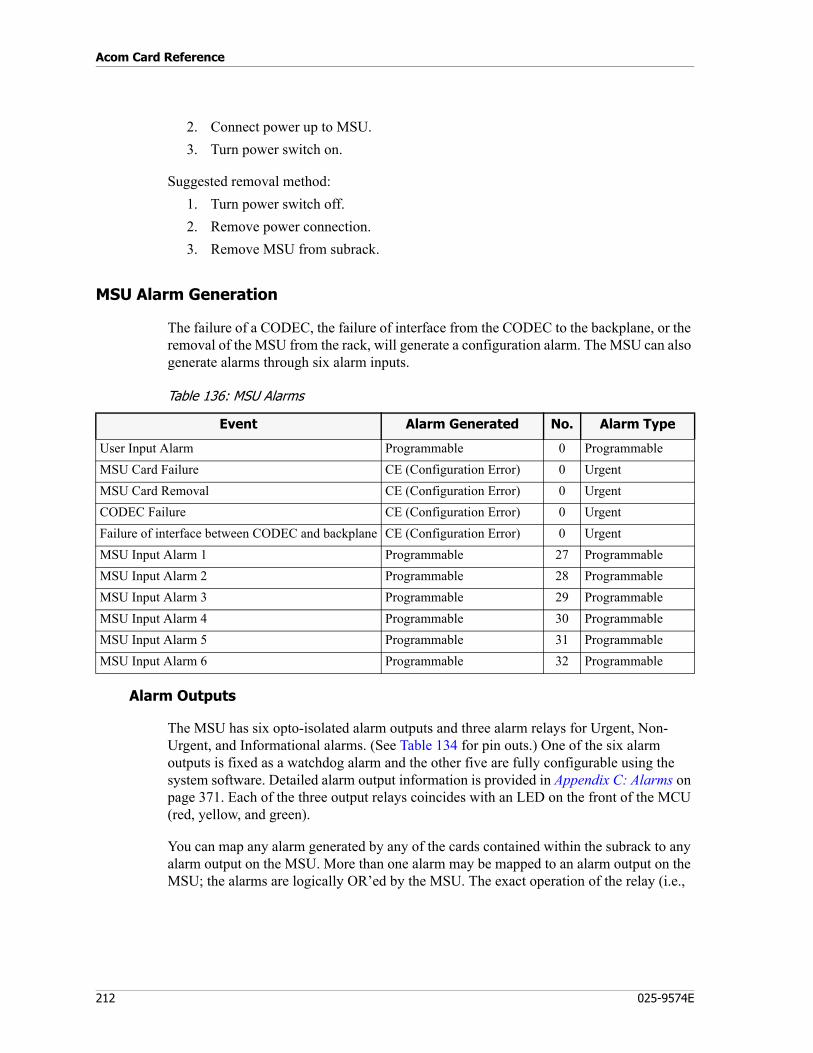
Acom Card Reference
212 025-9574E
2. Connect power up to MSU.3. Turn power switch on.
Suggested removal method:1. Turn power switch off.2. Remove power connection.3. Remove MSU from subrack.
MSU Alarm Generation
The failure of a CODEC, the failure of interface from the CODEC to the backplane, or the removal of the MSU from the rack, will generate a configuration alarm. The MSU can also generate alarms through six alarm inputs.
Table 136: MSU Alarms
Alarm Outputs
The MSU has six opto-isolated alarm outputs and three alarm relays for Urgent, Non-Urgent, and Informational alarms. (See Table 134 for pin outs.) One of the six alarm outputs is fixed as a watchdog alarm and the other five are fully configurable using the system software. Detailed alarm output information is provided in Appendix C: Alarms on page 371. Each of the three output relays coincides with an LED on the front of the MCU (red, yellow, and green).
You can map any alarm generated by any of the cards contained within the subrack to any alarm output on the MSU. More than one alarm may be mapped to an alarm output on the MSU; the alarms are logically OR’ed by the MSU. The exact operation of the relay (i.e.,
Event Alarm Generated No. Alarm Type
User Input Alarm Programmable 0 ProgrammableMSU Card Failure CE (Configuration Error) 0 UrgentMSU Card Removal CE (Configuration Error) 0 UrgentCODEC Failure CE (Configuration Error) 0 UrgentFailure of interface between CODEC and backplane CE (Configuration Error) 0 UrgentMSU Input Alarm 1 Programmable 27 ProgrammableMSU Input Alarm 2 Programmable 28 ProgrammableMSU Input Alarm 3 Programmable 29 ProgrammableMSU Input Alarm 4 Programmable 30 ProgrammableMSU Input Alarm 5 Programmable 31 ProgrammableMSU Input Alarm 6 Programmable 32 Programmable
213
Main Supply Unit (MSU)
normally open or normally closed) can be set by using jumpers on the MSU board. The operation of the alarms can also be inverted by using the system software.
Watchdog Alarm
The watchdog alarm (AO13) of the MSU is a fixed alarm. If the primary MCU stops responding, the watchdog alarm is activated. This mapping is fixed and cannot be removed, however other system alarms can be mapped to the watchdog alarm output.
While the Watchdog is fixed to alarm on loss of primary MCU or power, other alarms may be mapped to the output in addition to the fixed conditions.
Programmable Alarms
The other five alarms on the MSU are fully configurable. You can map any card alarms to any MSU alarm output.
Alarm Inputs
The MSU has six alarm inputs that can be used to generate alarms within the MSU. (See Table 134 for pinouts.) These inputs can be used to trigger output alarms, or perform functions such as ‘acknowledge all alarms.’ This mapping is done using the system software.
The alarm input circuits are designed to detect the presence of a ‘ground’ on their input and alarm outputs or to generate a ‘ground’ (+VV = Gnd, -VV = -20 to -70V). Jumper links on the MSU card allow the alarm reference voltages (VV) to be connected to the backplane power supply or to pins on the external connector P4. The external connection allows isolation of the input and output circuits from the subrack power supply.
MSU Technical Specifications
Table 137: Absolute Maximum Ratings
Note The alarm outputs for each unit are identical when two MSU’s are installed.
Note In the case of a power failure, the watchdog alarm (AO13) becomes active, however the watchdog LED does not illuminate.
Parameter Conditions Max
Operating Input Voltage (DC) - -60 VSignaling Out Line Current (M Lead) Peak maximum 150 mAVoltage applied to Alarm Lines - +VV + 0.2 VAlarm reference voltage +VV to -VV Peak maximum 70 VDC bias across audio inputs or outputs - 0 V
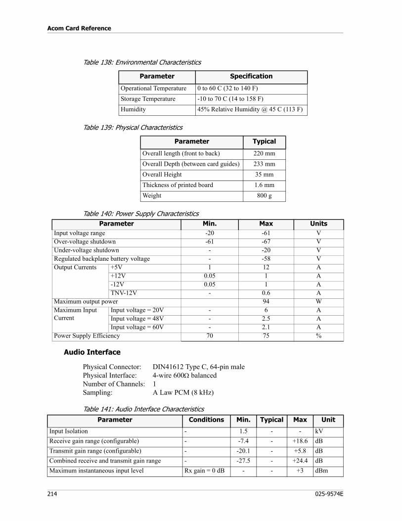
Acom Card Reference
214 025-9574E
Table 138: Environmental Characteristics
Table 139: Physical Characteristics
Table 140: Power Supply Characteristics
Audio Interface
Physical Connector: DIN41612 Type C, 64-pin malePhysical Interface: 4-wire 600Ω balancedNumber of Channels: 1Sampling: A Law PCM (8 kHz)
Table 141: Audio Interface Characteristics
Parameter Specification
Operational Temperature 0 to 60 C (32 to 140 F)Storage Temperature -10 to 70 C (14 to 158 F)Humidity 45% Relative Humidity @ 45 C (113 F)
Parameter Typical
Overall length (front to back) 220 mmOverall Depth (between card guides) 233 mmOverall Height 35 mmThickness of printed board 1.6 mmWeight 800 g
Parameter Min. Max UnitsInput voltage range -20 -61 VOver-voltage shutdown -61 -67 VUnder-voltage shutdown - -20 VRegulated backplane battery voltage - -58 VOutput Currents +5V 1 12 A
+12V 0.05 1 A-12V 0.05 1 ATNV-12V - 0.6 A
Maximum output power 94 WMaximum Input Current
Input voltage = 20V - 6 AInput voltage = 48V - 2.5 AInput voltage = 60V - 2.1 A
Power Supply Efficiency 70 75 %
Parameter Conditions Min. Typical Max Unit
Input Isolation - 1.5 - - kVReceive gain range (configurable) - -7.4 - +18.6 dBTransmit gain range (configurable) - -20.1 - +5.8 dBCombined receive and transmit gain range - -27.5 - +24.4 dBMaximum instantaneous input level Rx gain = 0 dB - - +3 dBm
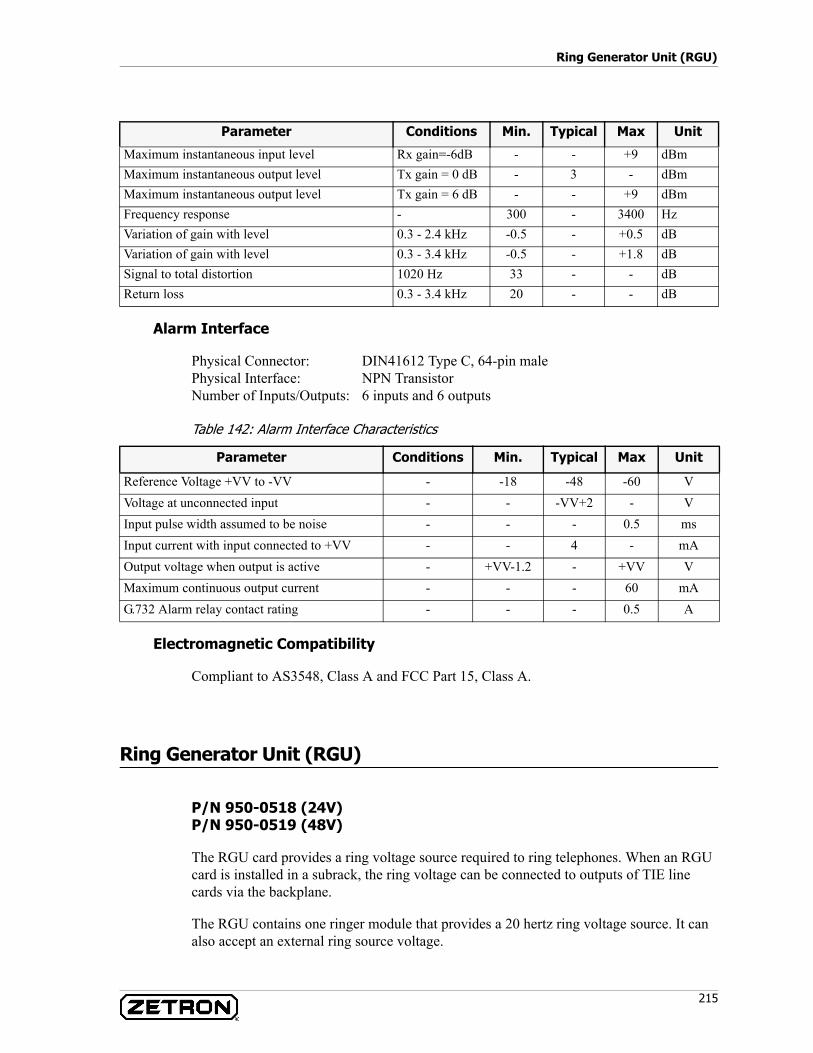
215
Ring Generator Unit (RGU)
Alarm Interface
Physical Connector: DIN41612 Type C, 64-pin malePhysical Interface: NPN TransistorNumber of Inputs/Outputs: 6 inputs and 6 outputs
Table 142: Alarm Interface Characteristics
Electromagnetic Compatibility
Compliant to AS3548, Class A and FCC Part 15, Class A.
Ring Generator Unit (RGU)
P/N 950-0518 (24V)P/N 950-0519 (48V)
The RGU card provides a ring voltage source required to ring telephones. When an RGU card is installed in a subrack, the ring voltage can be connected to outputs of TIE line cards via the backplane.
The RGU contains one ringer module that provides a 20 hertz ring voltage source. It can also accept an external ring source voltage.
Maximum instantaneous input level Rx gain=-6dB - - +9 dBmMaximum instantaneous output level Tx gain = 0 dB - 3 - dBmMaximum instantaneous output level Tx gain = 6 dB - - +9 dBmFrequency response - 300 - 3400 HzVariation of gain with level 0.3 - 2.4 kHz -0.5 - +0.5 dBVariation of gain with level 0.3 - 3.4 kHz -0.5 - +1.8 dBSignal to total distortion 1020 Hz 33 - - dBReturn loss 0.3 - 3.4 kHz 20 - - dB
Parameter Conditions Min. Typical Max Unit
Parameter Conditions Min. Typical Max Unit
Reference Voltage +VV to -VV - -18 -48 -60 VVoltage at unconnected input - - -VV+2 - VInput pulse width assumed to be noise - - - 0.5 msInput current with input connected to +VV - - 4 - mAOutput voltage when output is active - +VV-1.2 - +VV VMaximum continuous output current - - - 60 mAG.732 Alarm relay contact rating - - - 0.5 A

Acom Card Reference
216 025-9574E
The RGU can be configured to use either the internal ringer or the external ringer input. It can also use both in a Primary/Standby (when there is more than one ringer source) mode where the ringer source is switched if one ringer source fails.
The external ringer source input is also useful in applications where the number of telephones to be supplied exceeds the output rating of the internal ringer module.
The ring voltage output from the RGU is connected to the subrack backplane. TIE cards in the subrack take the ring voltage from the backplane and use a relay to connect the ring voltage to the TIE two-wire interfaces when a ring tone is required.
The RGU has the following functionality and features:• LED indication of the ringer voltage status (healthy or fail).• Automatic selection of a healthy ringer source when the Primary/Standby mode is
used.• Output short circuit protection of the internal ringer source.
RGU Description
Block Diagram
A functional block diagram of the RGU is illustrated in Figure 73. Table 143 describes each of these blocks in detail.
Figure 73: Functional Block Diagram
Ringer SourceSelector
InternalRingerOK
J2
RingerSource
Detector
+5
BackplaneConnector
- Bat
Power Fitter &Soft Start
FSI
Ringer SourceSelector
RingerModule
ExternalSource Input
Ringer SourceSelector
ExternalRingerOK
Ringer SourceDetector
BalancingTransformer Input
J1
Relays
Active Ringer Source
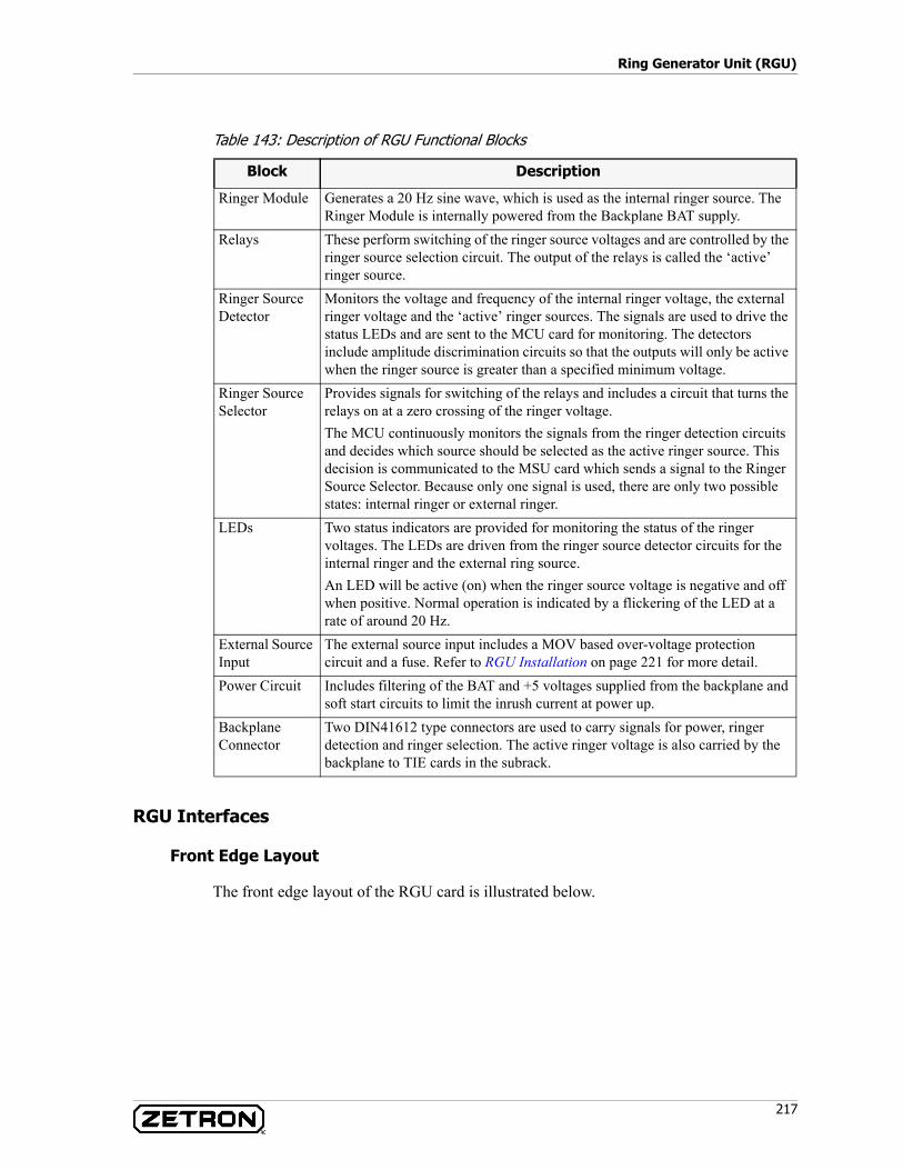
217
Ring Generator Unit (RGU)
Table 143: Description of RGU Functional Blocks
RGU Interfaces
Front Edge Layout
The front edge layout of the RGU card is illustrated below.
Block Description
Ringer Module Generates a 20 Hz sine wave, which is used as the internal ringer source. The Ringer Module is internally powered from the Backplane BAT supply.
Relays These perform switching of the ringer source voltages and are controlled by the ringer source selection circuit. The output of the relays is called the ‘active’ ringer source.
Ringer Source Detector
Monitors the voltage and frequency of the internal ringer voltage, the external ringer voltage and the ‘active’ ringer sources. The signals are used to drive the status LEDs and are sent to the MCU card for monitoring. The detectors include amplitude discrimination circuits so that the outputs will only be active when the ringer source is greater than a specified minimum voltage.
Ringer Source Selector
Provides signals for switching of the relays and includes a circuit that turns the relays on at a zero crossing of the ringer voltage.The MCU continuously monitors the signals from the ringer detection circuits and decides which source should be selected as the active ringer source. This decision is communicated to the MSU card which sends a signal to the Ringer Source Selector. Because only one signal is used, there are only two possible states: internal ringer or external ringer.
LEDs Two status indicators are provided for monitoring the status of the ringer voltages. The LEDs are driven from the ringer source detector circuits for the internal ringer and the external ring source.An LED will be active (on) when the ringer source voltage is negative and off when positive. Normal operation is indicated by a flickering of the LED at a rate of around 20 Hz.
External Source Input
The external source input includes a MOV based over-voltage protection circuit and a fuse. Refer to RGU Installation on page 221 for more detail.
Power Circuit Includes filtering of the BAT and +5 voltages supplied from the backplane and soft start circuits to limit the inrush current at power up.
BackplaneConnector
Two DIN41612 type connectors are used to carry signals for power, ringer detection and ringer selection. The active ringer voltage is also carried by the backplane to TIE cards in the subrack.
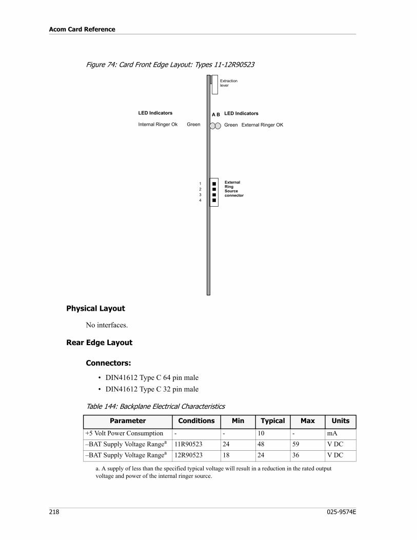
Acom Card Reference
218 025-9574E
Figure 74: Card Front Edge Layout: Types 11-12R90523
Physical Layout
No interfaces.
Rear Edge Layout
Connectors:
• DIN41612 Type C 64 pin male• DIN41612 Type C 32 pin male
Table 144: Backplane Electrical Characteristics
A B LED Indicators
Green External Ringer OK
Extractionlever
LED Indicators
Internal Ringer Ok Green
21 External
RingSourceconnector
43
Parameter Conditions Min Typical Max Units
+5 Volt Power Consumption - - 10 - mA–BAT Supply Voltage Rangea 11R90523 24 48 59 V DC–BAT Supply Voltage Rangea 12R90523 18 24 36 V DC
a. A supply of less than the specified typical voltage will result in a reduction in the rated output voltage and power of the internal ringer source.
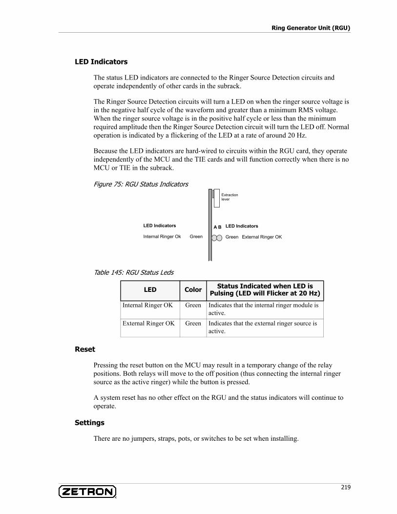
219
Ring Generator Unit (RGU)
LED Indicators
The status LED indicators are connected to the Ringer Source Detection circuits and operate independently of other cards in the subrack.
The Ringer Source Detection circuits will turn a LED on when the ringer source voltage is in the negative half cycle of the waveform and greater than a minimum RMS voltage. When the ringer source voltage is in the positive half cycle or less than the minimum required amplitude then the Ringer Source Detection circuit will turn the LED off. Normal operation is indicated by a flickering of the LED at a rate of around 20 Hz.
Because the LED indicators are hard-wired to circuits within the RGU card, they operate independently of the MCU and the TIE cards and will function correctly when there is no MCU or TIE in the subrack.
Figure 75: RGU Status Indicators
Table 145: RGU Status Leds
Reset
Pressing the reset button on the MCU may result in a temporary change of the relay positions. Both relays will move to the off position (thus connecting the internal ringer source as the active ringer) while the button is pressed.
A system reset has no other effect on the RGU and the status indicators will continue to operate.
Settings
There are no jumpers, straps, pots, or switches to be set when installing.
LED Color Status Indicated when LED is Pulsing (LED will Flicker at 20 Hz)
Internal Ringer OK Green Indicates that the internal ringer module is active.
External Ringer OK Green Indicates that the external ringer source is active.
A B LED Indicators
Green External Ringer OK
Extractionlever
LED Indicators
Internal Ringer Ok Green
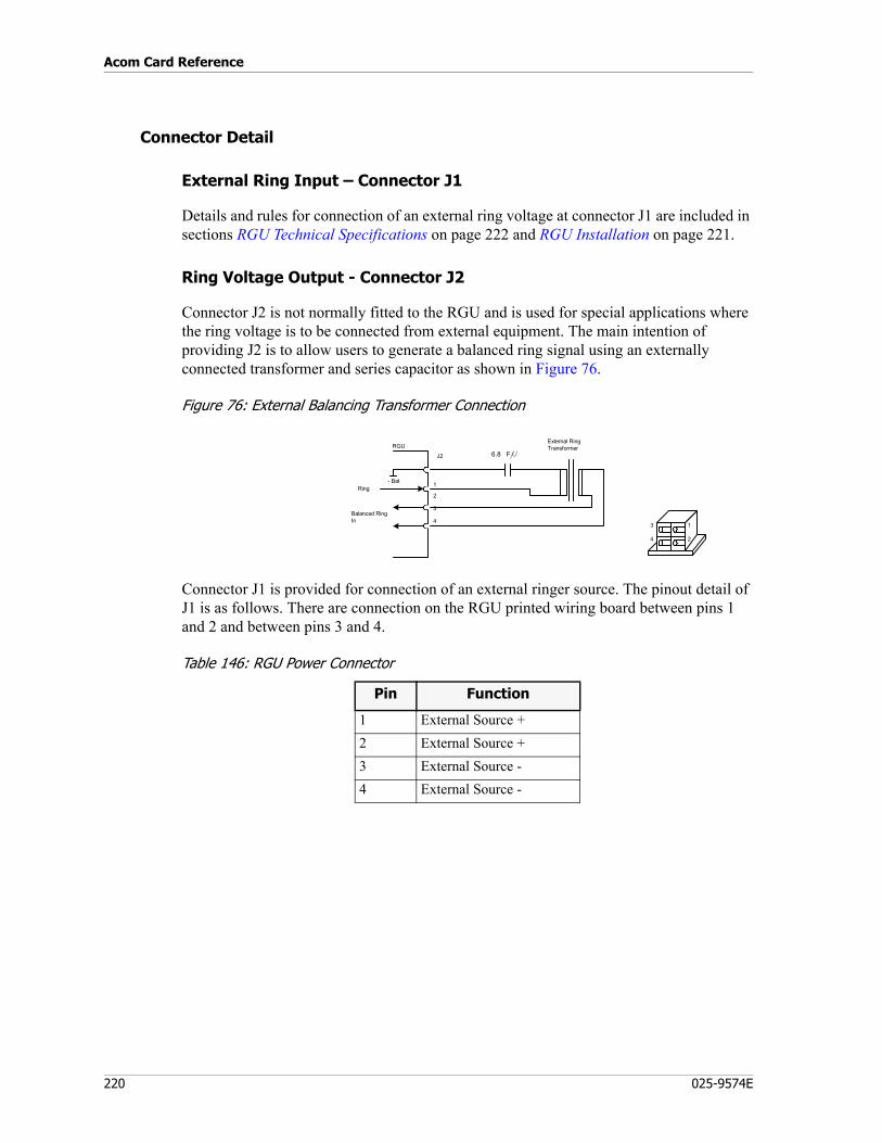
Acom Card Reference
220 025-9574E
Connector Detail
External Ring Input – Connector J1
Details and rules for connection of an external ring voltage at connector J1 are included in sections RGU Technical Specifications on page 222 and RGU Installation on page 221.
Ring Voltage Output - Connector J2
Connector J2 is not normally fitted to the RGU and is used for special applications where the ring voltage is to be connected from external equipment. The main intention of providing J2 is to allow users to generate a balanced ring signal using an externally connected transformer and series capacitor as shown in Figure 76.
Figure 76: External Balancing Transformer Connection
Connector J1 is provided for connection of an external ringer source. The pinout detail of J1 is as follows. There are connection on the RGU printed wiring board between pins 1 and 2 and between pins 3 and 4.
Table 146: RGU Power Connector
Pin Function
1 External Source +2 External Source +3 External Source -4 External Source -
1
2
3
4
External RingTransformerRGU
J2 6.8 F
Ring
Balanced RingIn
- Bat
3 1
4 2
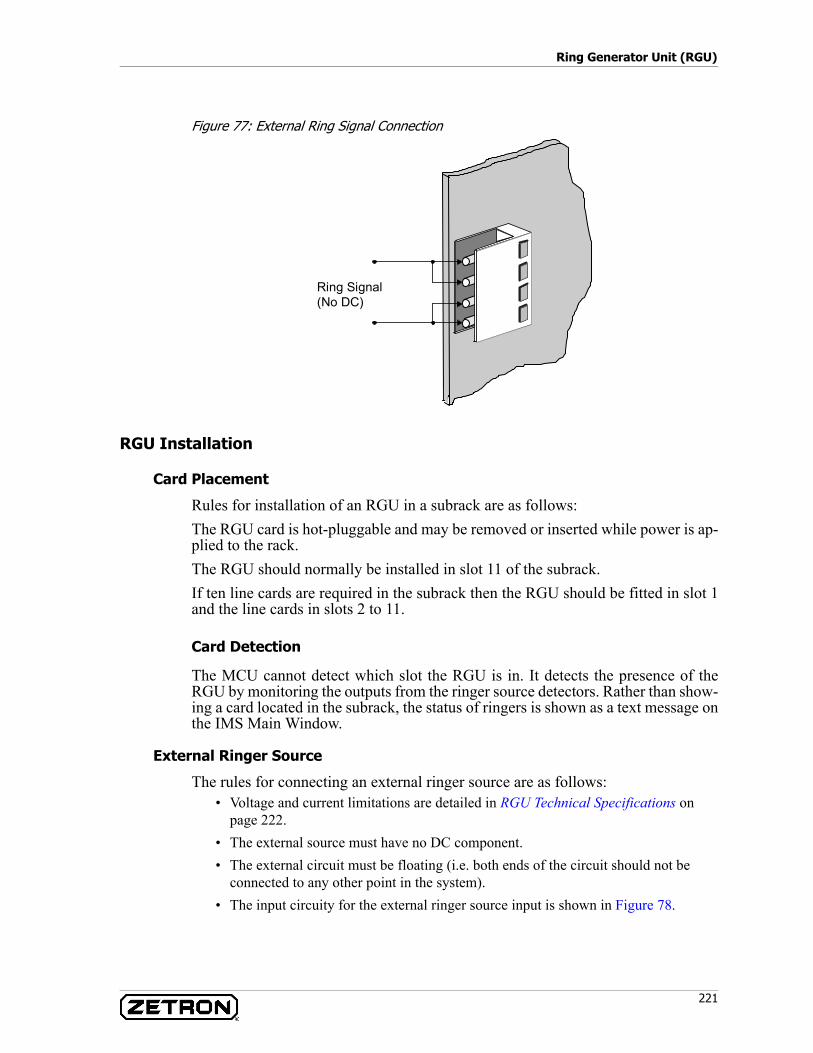
221
Ring Generator Unit (RGU)
Figure 77: External Ring Signal Connection
RGU Installation
Card Placement
Rules for installation of an RGU in a subrack are as follows:The RGU card is hot-pluggable and may be removed or inserted while power is ap-plied to the rack.The RGU should normally be installed in slot 11 of the subrack.If ten line cards are required in the subrack then the RGU should be fitted in slot 1and the line cards in slots 2 to 11.
Card Detection
The MCU cannot detect which slot the RGU is in. It detects the presence of theRGU by monitoring the outputs from the ringer source detectors. Rather than show-ing a card located in the subrack, the status of ringers is shown as a text message onthe IMS Main Window.
External Ringer Source
The rules for connecting an external ringer source are as follows:• Voltage and current limitations are detailed in RGU Technical Specifications on
page 222.• The external source must have no DC component.• The external circuit must be floating (i.e. both ends of the circuit should not be
connected to any other point in the system).• The input circuity for the external ringer source input is shown in Figure 78.
Ring Signal(No DC)
J1
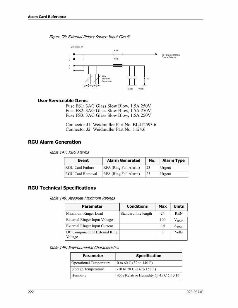
Acom Card Reference
222 025-9574E
Figure 78: External Ringer Source Input Circuit
User Serviceable ItemsFuse FS1: 3AG Glass Slow Blow, 1.5A 250VFuse FS2: 3AG Glass Slow Blow, 1.5A 250VFuse FS3: 3AG Glass Slow Blow, 1.5A 250V
Connector J1: Weidmuller Part No. BL412593.6Connector J2: Weidmuller Part No. 1124.6
RGU Alarm Generation
Table 147: RGU Alarms
RGU Technical Specifications
Table 148: Absolute Maximum Ratings
Table 149: Environmental Characteristics
12
34
To Relay and RingerSource Detector
10
+V Bat -V Bat
MoVTransientSupressors
FS3
FS2
Connector J1
Event Alarm Generated No. Alarm Type
RGU Card Failure RFA (Ring Fail Alarm) 23 UrgentRGU Card Removal RFA (Ring Fail Alarm) 23 Urgent
Parameter Conditions Max Units
Maximum Ringer Load Standard line length 24 RENExternal Ringer Input Voltage 100 VRMS
External Ringer Input Current 1.5 ARMS
DC Component of External Ring Voltage
0 Volts
Parameter Specification
Operational Temperature 0 to 60 C (32 to 140 F)Storage Temperature -10 to 70 C (14 to 158 F)Humidity 45% Relative Humidity @ 45 C (113 F)
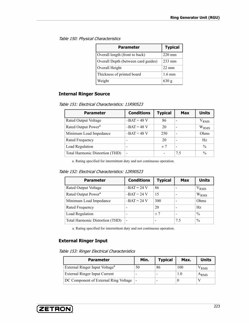
223
Ring Generator Unit (RGU)
Table 150: Physical Characteristics
Internal Ringer Source
Table 151: Electrical Characteristics: 11R90523
Table 152: Electrical Characteristics: 12R90523
External Ringer Input
Table 153: Ringer Electrical Characteristics
Parameter Typical
Overall length (front to back) 220 mmOverall Depth (between card guides) 233 mmOverall Height 22 mmThickness of printed board 1.6 mmWeight 630 g
Parameter Conditions Typical Max Units
Rated Output Voltage –BAT = 48 V 86 - VRMS
Rated Output Powera
a. Rating specified for intermittent duty and not continuous operation.
–BAT = 48 V 20 - WRMS
Minimum Load Impedance –BAT = 48 V 250 - OhmsRated Frequency - 20 - HzLoad Regulation - ± 7 - %Total Harmonic Distortion (THD) - - 7.5 %
Parameter Conditions Typical Max Units
Rated Output Voltage –BAT = 24 V 86 - VRMS
Rated Output Powera
a. Rating specified for intermittent duty and not continuous operation.
–BAT = 24 V 15 - WRMS
Minimum Load Impedance –BAT = 24 V 300 - OhmsRated Frequency - 20 - HzLoad Regulation - ± 7 - %Total Harmonic Distortion (THD) - - 7.5 %
Parameter Min. Typical Max. Units
External Ringer Input Voltagea 50 86 100 VRMS
External Ringer Input Current - - 1.0 ARMS
DC Component of External Ring Voltage - - 0 V

Acom Card Reference
224 025-9574E
Electromagnetic Compatibility
Compliant to AS3548 Class B.
Radio Interface Unit (RIU)
P/N 950-0838
The RIU is a card for the Acom Line Subrack (ALS) that provides interfaces for up to six conventional radio channels via local or tone remote control. The six channels can be configured to serve as an interface to a 2-wire or 4-wire tone remote base station, a local radio, or an E&M circuit*. Voice logger outputs are available for all six channels and all configurations.
The RIU card has LEDs that provide visible indication of COR (E) and PTT (M) status for each channel. Configuration and audio level adjustments are performed via the Integrated Management System (IMS).
a. A voltage below the specified minimum will not be properly detected by the RGU status monitoring circuits.
Note * The RIU does not have -48v capability on E&M lines.
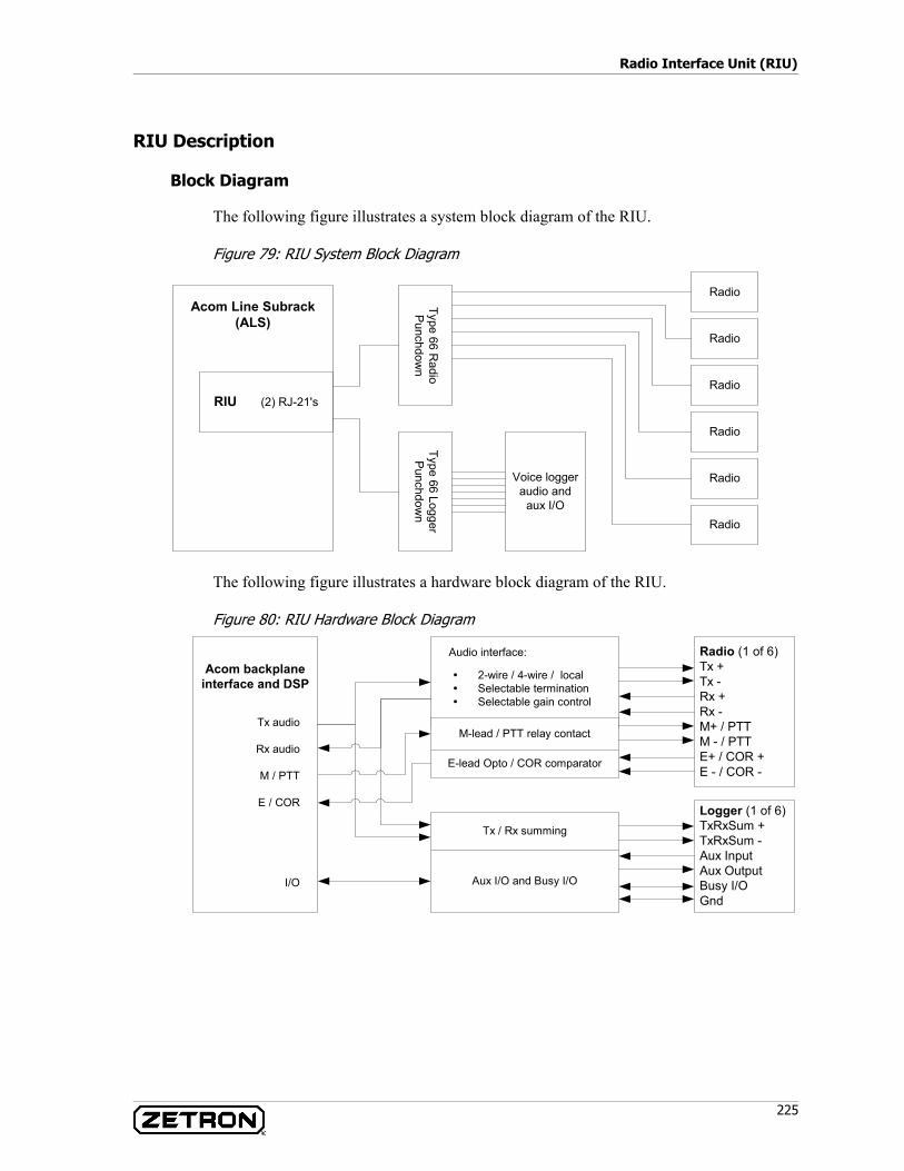
225
Radio Interface Unit (RIU)
RIU Description
Block Diagram
The following figure illustrates a system block diagram of the RIU.
Figure 79: RIU System Block Diagram
The following figure illustrates a hardware block diagram of the RIU.
Figure 80: RIU Hardware Block Diagram
Acom Line Subrack(ALS)
RIU (2) RJ-21's
Radio
Type 66 LoggerP
unchdown
Type 66 Radio
Punchdow
nVoice logger
audio andaux I/O
Radio
Radio
Radio
Radio
Radio
2-wire / 4-wire / localSelectable terminationSelectable gain control
Acom backplaneinterface and DSP
Tx audio
Rx audio
M / PTT
E / COR
I/O
Audio interface:
M-lead / PTT relay contact
E-lead Opto / COR comparator
Radio (1 of 6)Tx +Tx -Rx +Rx -M+ / PTTM - / PTTE+ / COR +E - / COR -
Tx / Rx summing
Aux I/O and Busy I/O
Logger (1 of 6)TxRxSum +TxRxSum -Aux InputAux OutputBusy I/OGnd
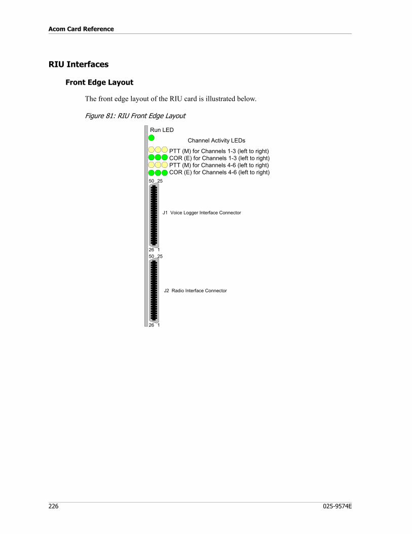
Acom Card Reference
226 025-9574E
RIU Interfaces
Front Edge Layout
The front edge layout of the RIU card is illustrated below.
Figure 81: RIU Front Edge Layout
PTT (M) for Channels 1-3 (left to right)COR (E) for Channels 1-3 (left to right)PTT (M) for Channels 4-6 (left to right)COR (E) for Channels 4-6 (left to right)
Channel Activity LEDs
25
1
50
2625
1
50
26
J2 Radio Interface Connector
J1 Voice Logger Interface Connector
Run LED

227
Radio Interface Unit (RIU)
Rear Edge Layout
The rear edge layout of the RIU card is illustrated below.
32
1C A
32
1
C A
P1
P2
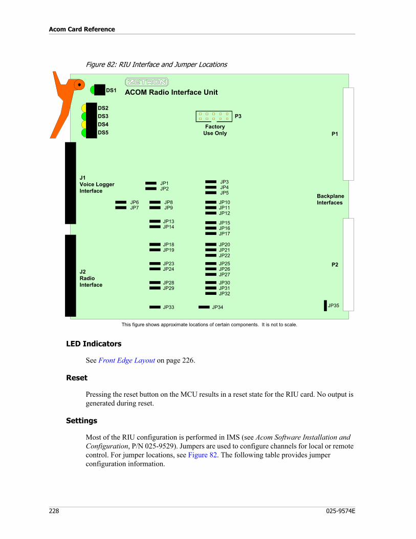
Acom Card Reference
228 025-9574E
Figure 82: RIU Interface and Jumper Locations
LED Indicators
See Front Edge Layout on page 226.
Reset
Pressing the reset button on the MCU results in a reset state for the RIU card. No output is generated during reset.
Settings
Most of the RIU configuration is performed in IMS (see Acom Software Installation and Configuration, P/N 025-9529). Jumpers are used to configure channels for local or remote control. For jumper locations, see Figure 82. The following table provides jumper configuration information.
This figure shows approximate locations of certain components. It is not to scale.
P1
P2
JP35
JP6
FactoryUse Only
ACOM Radio Interface UnitDS1
DS2DS3DS4DS5
J1Voice LoggerInterface
J2RadioInterface
JP7
JP1JP2
JP8JP9
JP13JP14
JP18JP19
JP23JP24
JP28JP29
JP33
JP3JP4JP5
JP10JP11JP12
JP15JP16JP17
JP20JP21JP22
JP25JP26JP27
JP30JP31JP32
JP34
P3
BackplaneInterfaces

229
Radio Interface Unit (RIU)
Table 154: RIU Jumpers
If any mixture of these Functions is used, set JP1=IN. (The only caveat is that you will not be able to connect telco lines to the card. This should not present any problem.)
Factory defaults JP34=OUT and JP35=A should never be changed.
Connector Detail
For connector locations, see Figure 82.
Voice Logger Connector (J1)
The RIU’s voice logger is just a line logger for the specific RIU channel it is attached to. The voice logger interface is a 50-pin RJ-21 connector with the following pinout:
Function Channel 1
Channel 2
Channel 3
Channel 4
Channel 5
Channel 6
Local Radio Interface COR and
PTT
JP29=BJP30=AJP31=INJP32=BJP33=B
JP24=BJP25=AJP26=INJP27=BJP28=B
JP19=BJP20=AJP21=INJP22=BJP23=B
JP14=BJP15=AJP16=INJP17=BJP18=B
JP9=BJP10=AJP11=INJP12=BJP13=B
JP2=BJP3=AJP4=INJP5=BJP8=B
Dry(no VBAT)
E&M
JP29=OUTJP30=AJP31=OUTJP32=AJP33=B
JP24=OUTJP25=AJP26=OUTJP27=AJP28=B
JP19=OUTJP20=AJP21=OUTJP22=AJP23=B
JP14=OUTJP15=AJP16=OUTJP17=AJP18=B
JP9=OUTJP10=AJP11=OUTJP12=AJP13=B
JP2=OUTJP3=AJP4=OUTJP5=AJP8=B
Pin Description Type Notes
1 CH1 Voice Logger + Audio Output Paired with Voice Logger -• Transformer coupled• RO = 600 ohm +/- 10 %• Shall be capable of driving +5 dBm into 600 ohm• Shall withstand > 50 VDC through 1k ohm
26 CH1 Voice Logger - Audio Output See Voice Logger +3 CH1 Busy I/O + Open
Collector I/OPaired with signal ground
• Open collector input/output with hysteresis on the input
• 10k ohm pull up to +12 VDC nominal• RACTIVE < 50 ohms, RINACTIVE > 10k ohm• Shall withstand > 50 VDC through 1k ohm
28 CH1 Busy I/O - Ground Signal ground
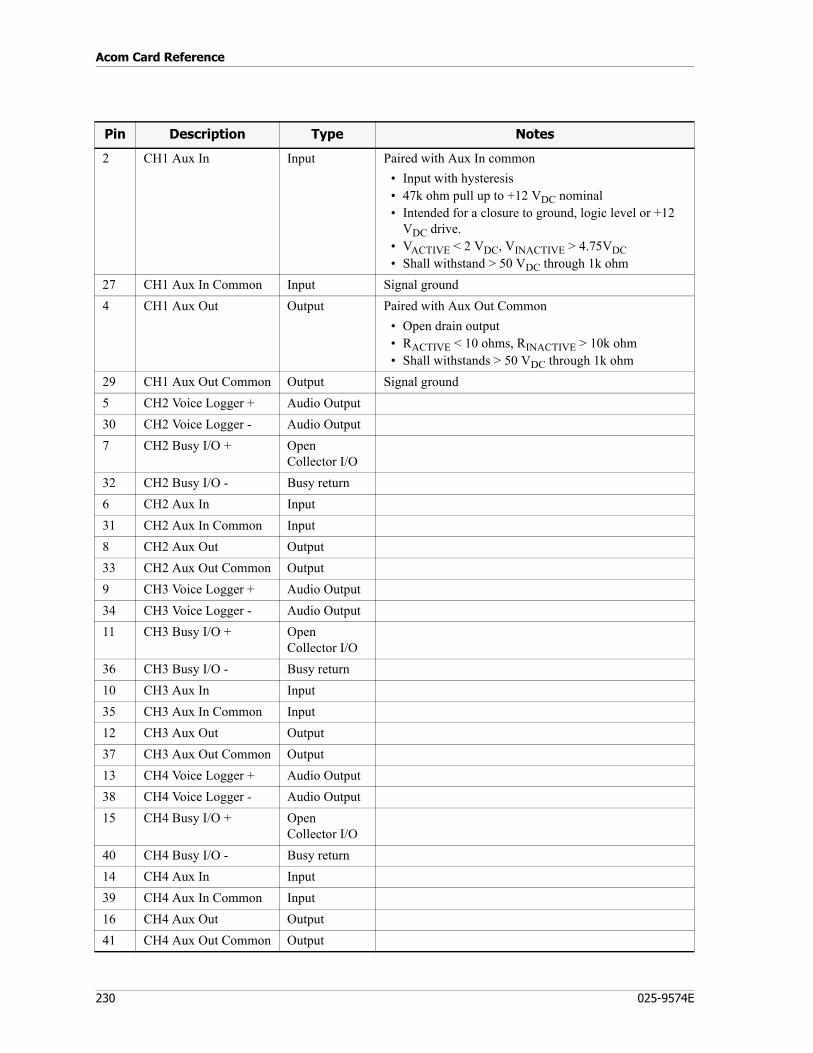
Acom Card Reference
230 025-9574E
2 CH1 Aux In Input Paired with Aux In common• Input with hysteresis• 47k ohm pull up to +12 VDC nominal • Intended for a closure to ground, logic level or +12
VDC drive.• VACTIVE < 2 VDC, VINACTIVE > 4.75VDC • Shall withstand > 50 VDC through 1k ohm
27 CH1 Aux In Common Input Signal ground 4 CH1 Aux Out Output Paired with Aux Out Common
• Open drain output• RACTIVE < 10 ohms, RINACTIVE > 10k ohm• Shall withstands > 50 VDC through 1k ohm
29 CH1 Aux Out Common Output Signal ground5 CH2 Voice Logger + Audio Output30 CH2 Voice Logger - Audio Output7 CH2 Busy I/O + Open
Collector I/O32 CH2 Busy I/O - Busy return6 CH2 Aux In Input31 CH2 Aux In Common Input 8 CH2 Aux Out Output33 CH2 Aux Out Common Output9 CH3 Voice Logger + Audio Output34 CH3 Voice Logger - Audio Output11 CH3 Busy I/O + Open
Collector I/O36 CH3 Busy I/O - Busy return10 CH3 Aux In Input35 CH3 Aux In Common Input 12 CH3 Aux Out Output37 CH3 Aux Out Common Output13 CH4 Voice Logger + Audio Output38 CH4 Voice Logger - Audio Output15 CH4 Busy I/O + Open
Collector I/O40 CH4 Busy I/O - Busy return14 CH4 Aux In Input39 CH4 Aux In Common Input 16 CH4 Aux Out Output41 CH4 Aux Out Common Output
Pin Description Type Notes
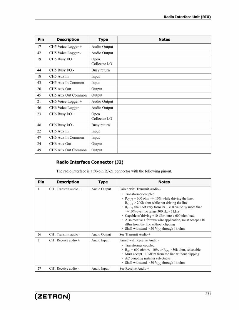
231
Radio Interface Unit (RIU)
Radio Interface Connector (J2)
The radio interface is a 50-pin RJ-21 connector with the following pinout.
17 CH5 Voice Logger + Audio Output42 CH5 Voice Logger - Audio Output19 CH5 Busy I/O + Open
Collector I/O44 CH5 Busy I/O - Busy return18 CH5 Aux In Input43 CH5 Aux In Common Input 20 CH5 Aux Out Output45 CH5 Aux Out Common Output21 CH6 Voice Logger + Audio Output46 CH6 Voice Logger - Audio Output23 CH6 Busy I/O + Open
Collector I/O48 CH6 Busy I/O - Busy return22 CH6 Aux In Input47 CH6 Aux In Common Input 24 CH6 Aux Out Output49 CH6 Aux Out Common Output
Pin Description Type Notes
Pin Description Type Notes
1 CH1 Transmit audio + Audio Output Paired with Transmit Audio -• Transformer coupled• ROUT = 600 ohm +/- 10% while driving the line,
ROUT > 200k ohm while not driving the line• ROUT shall not vary from its 1 kHz value by more than
+/-10% over the range 300 Hz - 3 kHz• Capable of driving +10 dBm into a 600 ohm load• Also receive + for two wire application, must accept +10
dBm from the line without clipping• Shall withstand > 50 VDC through 1k ohm
26 CH1 Transmit audio - Audio Output See Transmit Audio +
2 CH1 Receive audio + Audio Input Paired with Receive Audio -• Transformer coupled• RIN = 600 ohm +/- 10% or RIN > 50k ohm, selectable• Must accept +10 dBm from the line without clipping• AC coupling installer selectable• Shall withstand > 50 VDC through 1k ohm
27 CH1 Receive audio - Audio Input See Receive Audio +
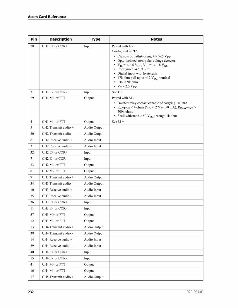
Acom Card Reference
232 025-9574E
28 CH1 E+ or COR+ Input Paired with E -Configured as "E":
• Capable of withstanding +/- 56.5 VDC• Opto-isolated, non-polar voltage detector• VIL = +/- .6 VDC, VIH = +/- 18 VDC• Configured as "COR":• Digital input with hysteresis• 47k ohm pull up to +12 VDC nominal• RIN > 9k ohm• VT ~ 2.5 VDC
3 CH1 E- or COR- Input See E +
29 CH1 M+ or PTT Output Paired with M -• Isolated relay contact capable of carrying 100 mA• RACTIVE < 4 ohms (VO < .2 V @ 50 mA), RINACTIVE >
500k ohms• Shall withstand > 50 VDC through 1k ohm
4 CH1 M- or PTT Output See M +
5 CH2 Transmit audio + Audio Output
30 CH2 Transmit audio - Audio Output
6 CH2 Receive audio + Audio Input
31 CH2 Receive audio - Audio Input
32 CH2 E+ or COR+ Input
7 CH2 E- or COR- Input
33 CH2 M+ or PTT Output
8 CH2 M- or PTT Output
9 CH3 Transmit audio + Audio Output
34 CH3 Transmit audio - Audio Output
10 CH3 Receive audio + Audio Input
35 CH3 Receive audio - Audio Input
36 CH3 E+ or COR+ Input
11 CH3 E- or COR- Input
37 CH3 M+ or PTT Output
12 CH3 M- or PTT Output
13 CH4 Transmit audio + Audio Output
38 CH4 Transmit audio - Audio Output
14 CH4 Receive audio + Audio Input
39 CH4 Receive audio - Audio Input
40 CH4 E+ or COR+ Input
15 CH4 E- or COR- Input
41 CH4 M+ or PTT Output
16 CH4 M- or PTT Output
17 CH5 Transmit audio + Audio Output
Pin Description Type Notes
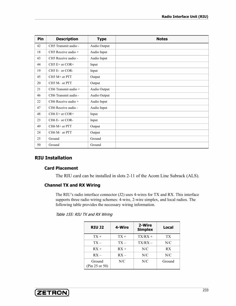
233
Radio Interface Unit (RIU)
RIU Installation
Card Placement
The RIU card can be installed in slots 2-11 of the Acom Line Subrack (ALS).
Channel TX and RX Wiring
The RIU’s radio interface connector (J2) uses 4-wires for TX and RX. This interface supports three radio wiring schemes: 4-wire, 2-wire simplex, and local radios. The following table provides the necessary wiring information.
Table 155: RIU TX and RX Wiring
42 CH5 Transmit audio - Audio Output
18 CH5 Receive audio + Audio Input
43 CH5 Receive audio - Audio Input
44 CH5 E+ or COR+ Input
19 CH5 E- or COR- Input
45 CH5 M+ or PTT Output
20 CH5 M- or PTT Output
21 CH6 Transmit audio + Audio Output
46 CH6 Transmit audio - Audio Output
22 CH6 Receive audio + Audio Input
47 CH6 Receive audio - Audio Input
48 CH6 E+ or COR+ Input
23 CH6 E- or COR- Input
49 CH6 M+ or PTT Output
24 CH6 M- or PTT Output
25 Ground Ground
50 Ground Ground
Pin Description Type Notes
RIU J2 4-Wire 2-Wire Simplex Local
TX + TX + TX/RX + TXTX – TX – TX/RX – N/CRX + RX + N/C RXRX – RX – N/C N/C
Ground(Pin 25 or 50)
N/C N/C Ground
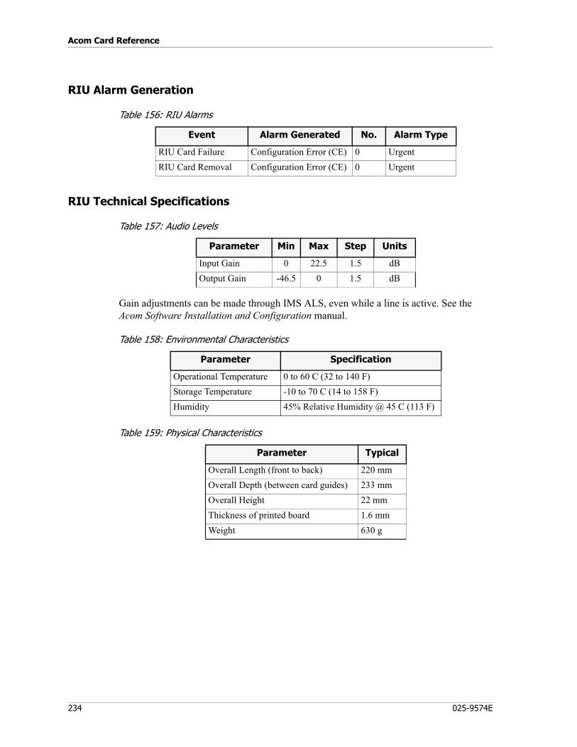
Acom Card Reference
234 025-9574E
RIU Alarm Generation
Table 156: RIU Alarms
RIU Technical Specifications
Table 157: Audio Levels
Gain adjustments can be made through IMS ALS, even while a line is active. See the Acom Software Installation and Configuration manual.
Table 158: Environmental Characteristics
Table 159: Physical Characteristics
Event Alarm Generated No. Alarm Type
RIU Card Failure Configuration Error (CE) 0 UrgentRIU Card Removal Configuration Error (CE) 0 Urgent
Parameter Min Max Step Units
Input Gain 0 22.5 1.5 dBOutput Gain -46.5 0 1.5 dB
Parameter Specification
Operational Temperature 0 to 60 C (32 to 140 F)Storage Temperature -10 to 70 C (14 to 158 F)Humidity 45% Relative Humidity @ 45 C (113 F)
Parameter Typical
Overall Length (front to back) 220 mmOverall Depth (between card guides) 233 mmOverall Height 22 mmThickness of printed board 1.6 mmWeight 630 g
235
Recorded Voice Announcement (RVA) Card
Recorded Voice Announcement (RVA) Card
P/N 950-0650
The Recorded Voice Announcement (RVA) card provides playback of recorded announcements. Multiple announcements may be recorded and stored in non-volatile memory. The playing back of the announcement is controlled by pre-determined events set up within the system.
The announcements stored in the RVA are downloaded into the cards non-volatile memory via Zetron maintenance terminal software. The RVA accepts 8kHz, 8-bit mono .wav files. If required, announcements can be recorded directly into the RVA via a handset that plugs into the RJ12 socket on the front of the card.
The RVA has the following functionality and features:• RVA playback uses the A-law PCM format• Announcements are stored in non-volatile memory (i.e. retained during power
down)• 516 seconds of total record time• Longest single announcement length of 30 seconds• Maximum of 30 separate recordings• Maximum of 30 simultaneous playbacks of one or more recordings• Able to playback an announcement while recording a new announcement• A dual purpose reset / heartbeat LED indicator.• Date / time stamp and name (up to 30 characters) for each announcement stored in
the non-volatile memory• RJ12 socket for recording and playback of announcement messages (invoked via
debug mode only)
RVA Block Diagram
A functional block diagram of the RVA is illustrated in Figure 83. Table 160 describes each of these blocks in detail.
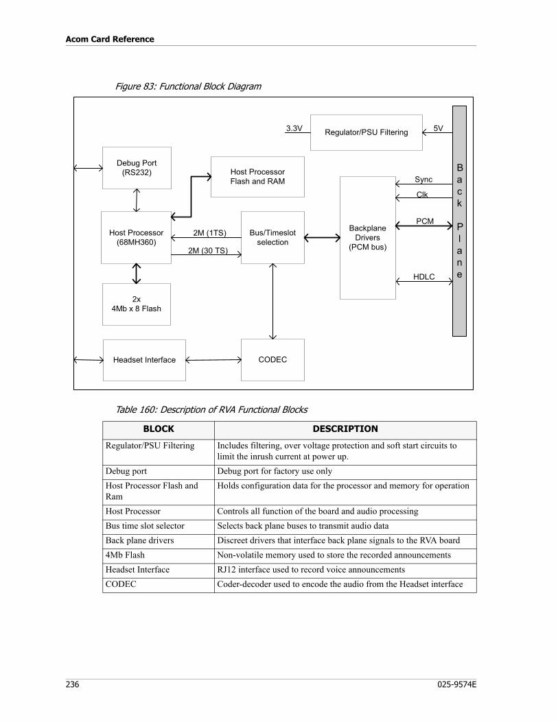
Acom Card Reference
236 025-9574E
Figure 83: Functional Block Diagram
Table 160: Description of RVA Functional Blocks
BackplaneDrivers
(PCM bus)
Regulator/PSU Filtering
Clk
Sync
5V
PCM
3.3V
Host Processor(68MH360)
Bus/Timeslotselection
HDLC
2M (30 TS)
Host ProcessorFlash and RAM
Debug Port(RS232)
2M (1TS)
2x4Mb x 8 Flash
Headset Interface CODEC
Back
Plane
BLOCK DESCRIPTION
Regulator/PSU Filtering Includes filtering, over voltage protection and soft start circuits to limit the inrush current at power up.
Debug port Debug port for factory use onlyHost Processor Flash and Ram
Holds configuration data for the processor and memory for operation
Host Processor Controls all function of the board and audio processingBus time slot selector Selects back plane buses to transmit audio dataBack plane drivers Discreet drivers that interface back plane signals to the RVA board4Mb Flash Non-volatile memory used to store the recorded announcementsHeadset Interface RJ12 interface used to record voice announcementsCODEC Coder-decoder used to encode the audio from the Headset interface
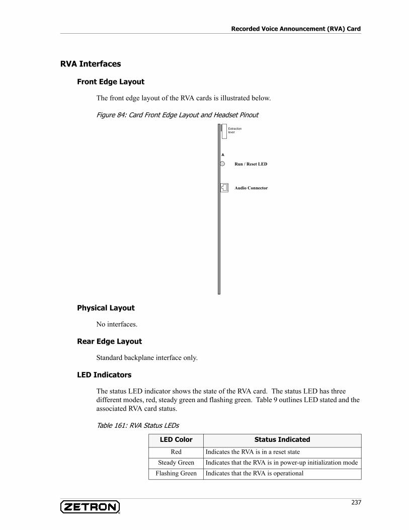
237
Recorded Voice Announcement (RVA) Card
RVA Interfaces
Front Edge Layout
The front edge layout of the RVA cards is illustrated below.
Figure 84: Card Front Edge Layout and Headset Pinout
Physical Layout
No interfaces.
Rear Edge Layout
Standard backplane interface only.
LED Indicators
The status LED indicator shows the state of the RVA card. The status LED has three different modes, red, steady green and flashing green. Table 9 outlines LED stated and the associated RVA card status.
Table 161: RVA Status LEDs
A
Extraction lever
Audio Connector
Run / Reset LED
LED Color Status Indicated
Red Indicates the RVA is in a reset stateSteady Green Indicates that the RVA is in power-up initialization mode
Flashing Green Indicates that the RVA is operational
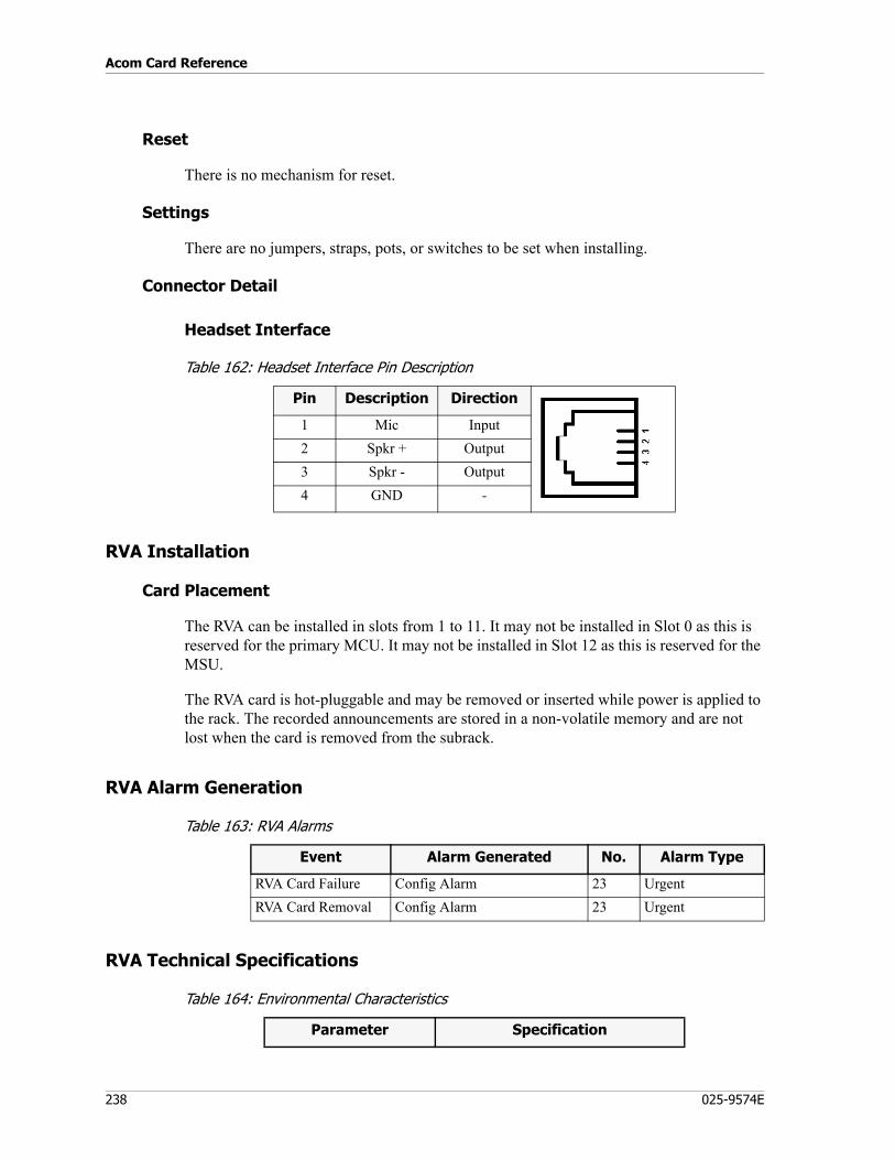
Acom Card Reference
238 025-9574E
Reset
There is no mechanism for reset.
Settings
There are no jumpers, straps, pots, or switches to be set when installing.
Connector Detail
Headset Interface
Table 162: Headset Interface Pin Description
RVA Installation
Card Placement
The RVA can be installed in slots from 1 to 11. It may not be installed in Slot 0 as this is reserved for the primary MCU. It may not be installed in Slot 12 as this is reserved for the MSU.
The RVA card is hot-pluggable and may be removed or inserted while power is applied to the rack. The recorded announcements are stored in a non-volatile memory and are not lost when the card is removed from the subrack.
RVA Alarm Generation
Table 163: RVA Alarms
RVA Technical Specifications
Table 164: Environmental Characteristics
Pin Description Direction
1 Mic Input2 Spkr + Output3 Spkr - Output4 GND -
Event Alarm Generated No. Alarm Type
RVA Card Failure Config Alarm 23 UrgentRVA Card Removal Config Alarm 23 Urgent
Parameter Specification
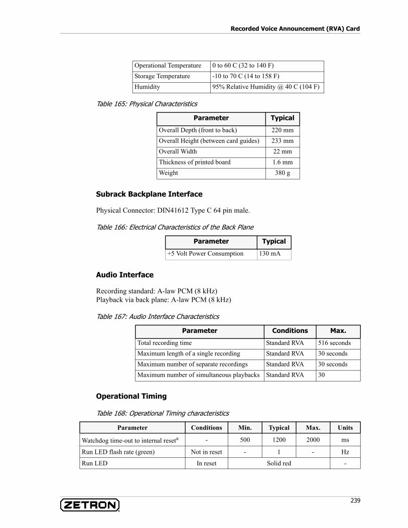
239
Recorded Voice Announcement (RVA) Card
Table 165: Physical Characteristics
Subrack Backplane Interface
Physical Connector: DIN41612 Type C 64 pin male.
Table 166: Electrical Characteristics of the Back Plane
Audio Interface
Recording standard: A-law PCM (8 kHz)Playback via back plane: A-law PCM (8 kHz)
Table 167: Audio Interface Characteristics
Operational Timing
Table 168: Operational Timing characteristics
Operational Temperature 0 to 60 C (32 to 140 F)Storage Temperature -10 to 70 C (14 to 158 F)Humidity 95% Relative Humidity @ 40 C (104 F)
Parameter Typical
Overall Depth (front to back) 220 mmOverall Height (between card guides) 233 mmOverall Width 22 mmThickness of printed board 1.6 mmWeight 380 g
Parameter Typical
+5 Volt Power Consumption 130 mA
Parameter Conditions Max.
Total recording time Standard RVA 516 secondsMaximum length of a single recording Standard RVA 30 secondsMaximum number of separate recordings Standard RVA 30 secondsMaximum number of simultaneous playbacks Standard RVA 30
Parameter Conditions Min. Typical Max. Units
Watchdog time-out to internal reseta - 500 1200 2000 ms
Run LED flash rate (green) Not in reset - 1 - Hz
Run LED In reset Solid red -
Acom Card Reference
240 025-9574E
Signaling Management Unit (SMU)
P/N 950-0512
The Signaling Management Unit (SMU) contains a microprocessor and up to three Digital Signal Processors (DSP), providing a general purpose signal processing resource for Acom systems. It also contains an IEEE 802.3 Ethernet port (10 Base-T) and a diagnostic serial port. With the optional SMU Adapter board (R93634), up to two of the Operators Console Unit analog-daughter boards can be mounted to the SMU board for additional I/O capability.
The microprocessor’s main functions are to communicate with the MCU card in slot 0 of the subrack and to manage the on-board signal processing and I/O resources. This includes translating resource allocation commands from the MCU and reporting operational status.
The SMU communicates with the MCU over an HDLC circuit on the subrack. It also has an RS-232 serial debugging port and status LED on the front of the card. The Ethernet port also has two diagnostic LEDs near the front of the card.
The SMU board supports up to three Digital Signal Processors to process the digitized audio information contained in the subrack PCM buses. These DSPs are connected through the FPGA to the PCM busses on the backplane and to the I/O connector to any daughter boards. A wide range of additional signal processing or specialized I/O capabilities are possible by designing daughter boards that mount on the SMU board and interface through the 100-pin I/O connector.
SMU interface circuits include the PCM and HDLC control buses, which are used to communicate with other cards in the subrack. These control buses are connected between cards by the backplane.
Multiple SMU cards can be installed in slots 1 through 11 of a subrack.
The DSP processing capabilities on the SMU provides the following functions:• Selective Calling (SELCAL) encoding and decoding• DTMF encoding and decoding• Complex tone generation with programmable tone type, frequency amplitude, and
duration• Voice detection (VOX)• Voice compression
a. The operation of the Watchdog Timer causes an internal reset only and does not cause the subrack to reset.
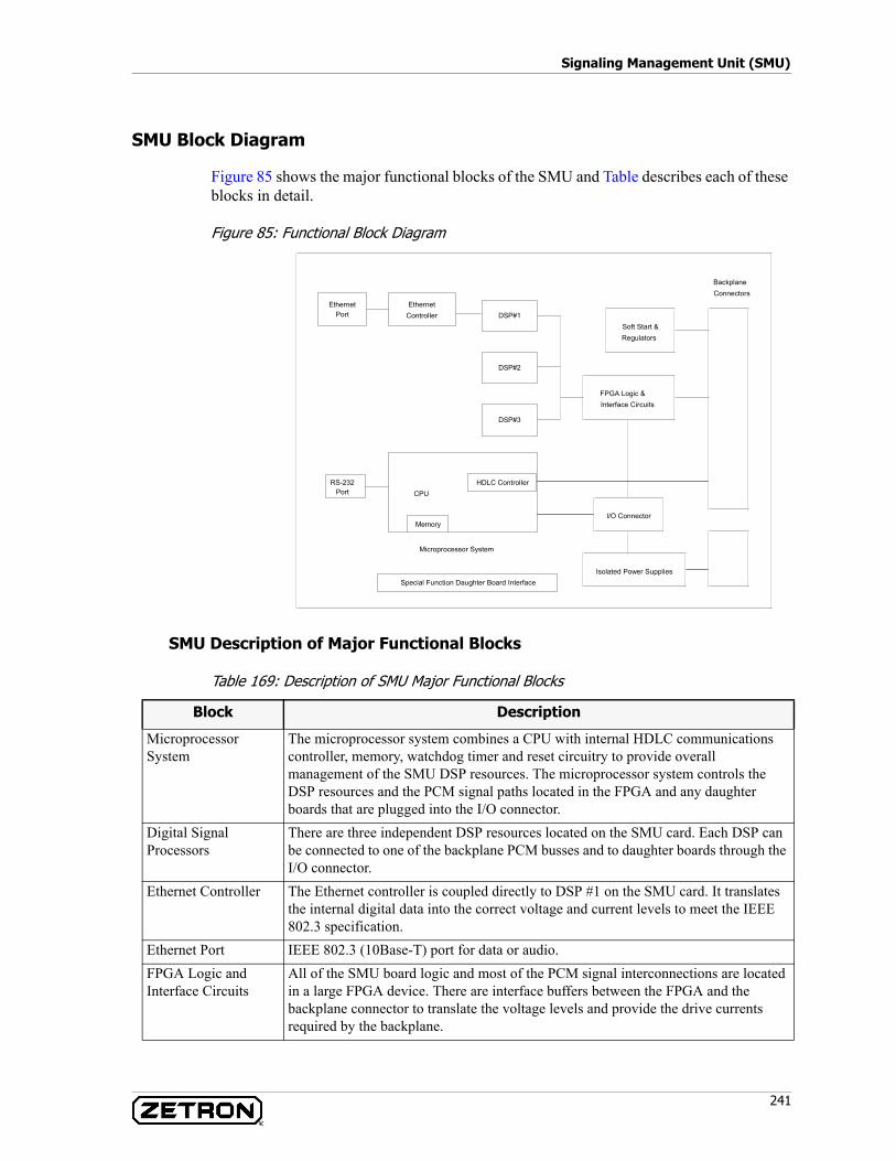
241
Signaling Management Unit (SMU)
SMU Block Diagram
Figure 85 shows the major functional blocks of the SMU and Table describes each of these blocks in detail.
Figure 85: Functional Block Diagram
SMU Description of Major Functional Blocks
Table 169: Description of SMU Major Functional Blocks
BackplaneConnectors
EthernetController
Soft Start &Regulators
FPGA Logic &Interface Circuits
RS-232 HDLC ControllerPort CPU
I/O ConnectorMemory
Microprocessor System
Isolated Power Supplies
DSP#3
DSP#2
DSP#1Ethernet
Port
Special Function Daughter Board Interface
Block Description
Microprocessor System
The microprocessor system combines a CPU with internal HDLC communications controller, memory, watchdog timer and reset circuitry to provide overall management of the SMU DSP resources. The microprocessor system controls the DSP resources and the PCM signal paths located in the FPGA and any daughter boards that are plugged into the I/O connector.
Digital Signal Processors
There are three independent DSP resources located on the SMU card. Each DSP can be connected to one of the backplane PCM busses and to daughter boards through the I/O connector.
Ethernet Controller The Ethernet controller is coupled directly to DSP #1 on the SMU card. It translates the internal digital data into the correct voltage and current levels to meet the IEEE 802.3 specification.
Ethernet Port IEEE 802.3 (10Base-T) port for data or audio.FPGA Logic and Interface Circuits
All of the SMU board logic and most of the PCM signal interconnections are located in a large FPGA device. There are interface buffers between the FPGA and the backplane connector to translate the voltage levels and provide the drive currents required by the backplane.
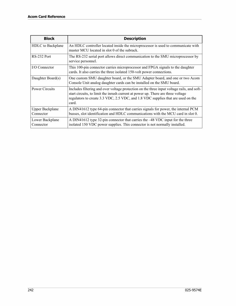
Acom Card Reference
242 025-9574E
HDLC to Backplane An HDLC controller located inside the microprocessor is used to communicate with master MCU located in slot 0 of the subrack.
RS-232 Port The RS-232 serial port allows direct communication to the SMU microprocessor by service personnel.
I/O Connector This 100-pin connector carries microprocessor and FPGA signals to the daughter cards. It also carries the three isolated 150-volt power connections.
Daughter Board(s) One custom SMU daughter board, or the SMU Adapter board, and one or two Acom Console Unit analog daughter cards can be installed on the SMU board.
Power Circuits Includes filtering and over voltage protection on the three input voltage rails, and soft-start circuits, to limit the inrush current at power up. There are three voltage regulators to create 3.3 VDC, 2.5 VDC, and 1.8 VDC supplies that are used on the card.
Upper Backplane Connector
A DIN41612 type 64-pin connector that carries signals for power, the internal PCM busses, slot identification and HDLC communications with the MCU card in slot 0.
Lower Backplane Connector
A DIN41612 type 32-pin connector that carries the –48 VDC input for the three isolated 150 VDC power supplies. This connector is not normally installed.
Block Description

243
Signaling Management Unit (SMU)
SMU Interfaces
Front Edge Layout
Figure 86: SMU - Front Edge Layout
The front edge of the SMU in Figure 86 has an Ethernet connector, a Run LED, and the Diagnostic RS-232 connector.
Physical Layout
The SMU layout of major components is shown in Table 87. For a detailed layout of all components, see the SMU Component Overlay drawing (Zetron No. 410-0072).
LEVEREXTRACTION
ETHERNETPORT
X5
RUN LEDV6
RS-232 PORTX14
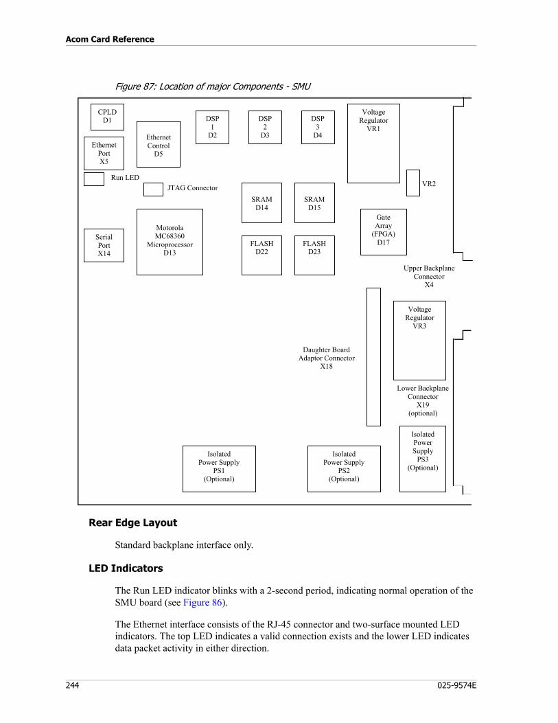
Acom Card Reference
244 025-9574E
Figure 87: Location of major Components - SMU
Rear Edge Layout
Standard backplane interface only.
LED Indicators
The Run LED indicator blinks with a 2-second period, indicating normal operation of the SMU board (see Figure 86).
The Ethernet interface consists of the RJ-45 connector and two-surface mounted LED indicators. The top LED indicates a valid connection exists and the lower LED indicates data packet activity in either direction.
Lower BackplaneConnector
X19(optional)
Run LED
Upper BackplaneConnector
X4
IsolatedPowerSupply
PS3(Optional)
VoltageRegulator
VR3
IsolatedPower Supply
PS2(Optional)
IsolatedPower Supply
PS1(Optional)
GateArray
(FPGA)D17
VoltageRegulator
VR1
MotorolaMC68360
MicroprocessorD13
FLASHD23
FLASHD22
SRAMD15
SRAMD14
DSP3
D4
DSP2
D3
DSP1
D2
Daughter BoardAdaptor Connector
X18
VR2
EthernetControl
D5
CPLDD1
SerialPortX14
JTAG Connector
EthernetPortX5
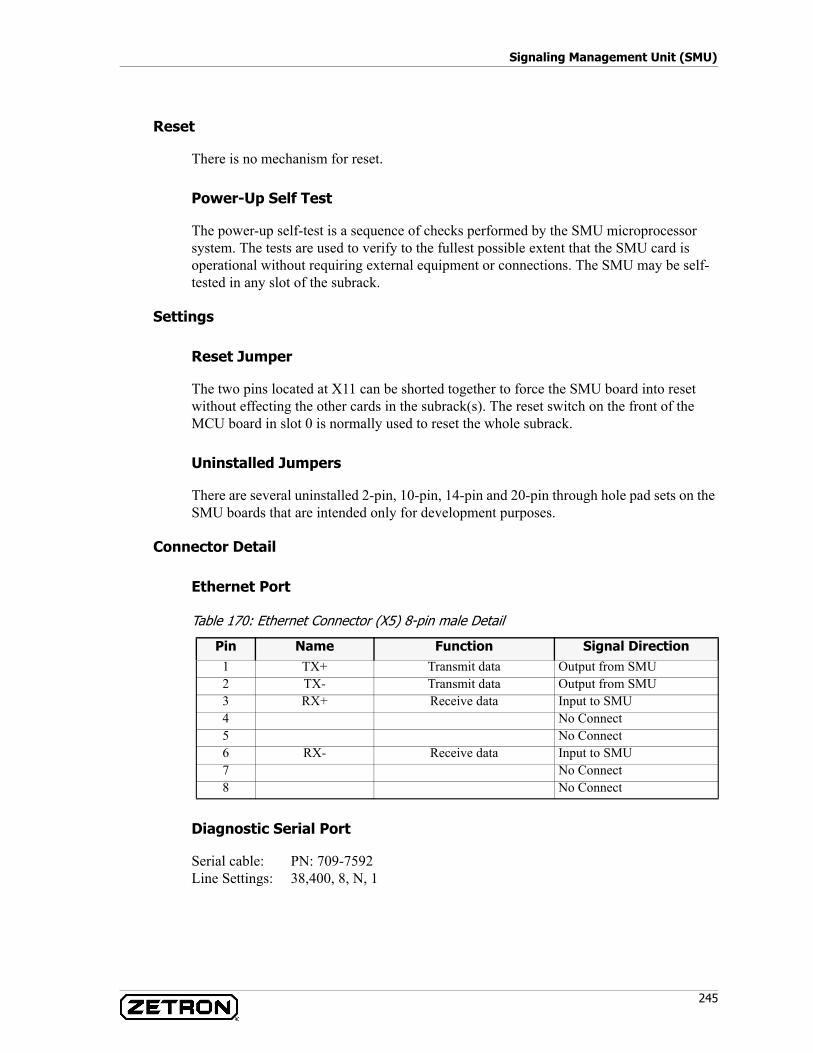
245
Signaling Management Unit (SMU)
Reset
There is no mechanism for reset.
Power-Up Self Test
The power-up self-test is a sequence of checks performed by the SMU microprocessor system. The tests are used to verify to the fullest possible extent that the SMU card is operational without requiring external equipment or connections. The SMU may be self-tested in any slot of the subrack.
Settings
Reset Jumper
The two pins located at X11 can be shorted together to force the SMU board into reset without effecting the other cards in the subrack(s). The reset switch on the front of the MCU board in slot 0 is normally used to reset the whole subrack.
Uninstalled Jumpers
There are several uninstalled 2-pin, 10-pin, 14-pin and 20-pin through hole pad sets on the SMU boards that are intended only for development purposes.
Connector Detail
Ethernet Port
Table 170: Ethernet Connector (X5) 8-pin male Detail
Diagnostic Serial Port
Serial cable: PN: 709-7592Line Settings: 38,400, 8, N, 1
Pin Name Function Signal Direction1 TX+ Transmit data Output from SMU2 TX- Transmit data Output from SMU3 RX+ Receive data Input to SMU4 No Connect5 No Connect6 RX- Receive data Input to SMU7 No Connect8 No Connect
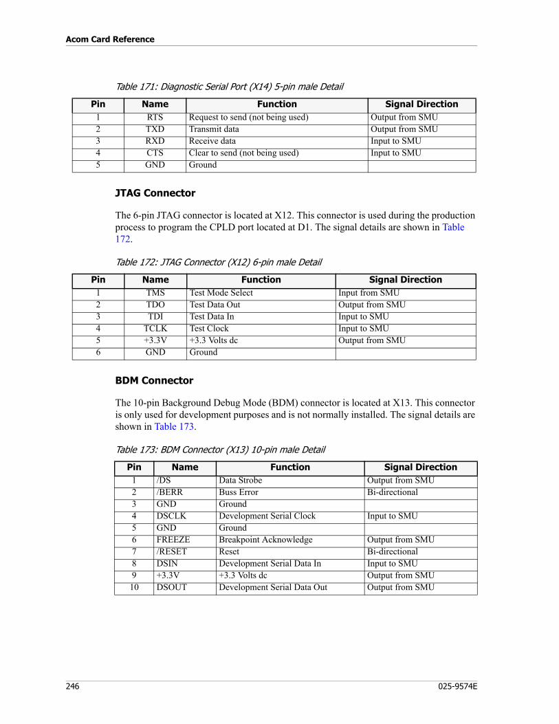
Acom Card Reference
246 025-9574E
Table 171: Diagnostic Serial Port (X14) 5-pin male Detail
JTAG Connector
The 6-pin JTAG connector is located at X12. This connector is used during the production process to program the CPLD port located at D1. The signal details are shown in Table 172.
Table 172: JTAG Connector (X12) 6-pin male Detail
BDM Connector
The 10-pin Background Debug Mode (BDM) connector is located at X13. This connector is only used for development purposes and is not normally installed. The signal details are shown in Table 173.
Table 173: BDM Connector (X13) 10-pin male Detail
Pin Name Function Signal Direction1 RTS Request to send (not being used) Output from SMU2 TXD Transmit data Output from SMU3 RXD Receive data Input to SMU4 CTS Clear to send (not being used) Input to SMU5 GND Ground
Pin Name Function Signal Direction1 TMS Test Mode Select Input from SMU2 TDO Test Data Out Output from SMU3 TDI Test Data In Input to SMU4 TCLK Test Clock Input to SMU5 +3.3V +3.3 Volts dc Output from SMU6 GND Ground
Pin Name Function Signal Direction1 /DS Data Strobe Output from SMU2 /BERR Buss Error Bi-directional3 GND Ground4 DSCLK Development Serial Clock Input to SMU5 GND Ground6 FREEZE Breakpoint Acknowledge Output from SMU7 /RESET Reset Bi-directional8 DSIN Development Serial Data In Input to SMU9 +3.3V +3.3 Volts dc Output from SMU10 DSOUT Development Serial Data Out Output from SMU
247
Signaling Management Unit (SMU)
Time Slot Connections
The SMU can be used to connect one or more time slots within the subrack. A description of time slot connection types can be found in the IMS chapter of the Acom Software Installation and Configuration manual (P/N 025-9529).
The time slot connections made on the SMU card are application dependent and are directed by the MCU located in slot 0.
Ethernet Interface
The Ethernet interface consists of the RJ-45 connector (X5), transformer (T1), controller (D5), nonvolatile memory (D6), and two surface mounted LED indicators. The top LED (V2) indicates a valid connection exists; the lower LED (V3) indicates data packet activity in either direction. DSP1 (D2) controls the Ethernet Controller through the CPLD (D1). The CPLD is used to expand the number of I/O addresses needed to control the Ethernet Controller and match the signal timing between the two ICs. DSP1 doubles the 39.00104 MHz clock input it receives from PLL (D8) to 78.00208 MHz for the internal timing in the CPLD IC. The Ethernet MAC address is stored in the nonvolatile memory (D6). The Ethernet interface is optimized for 100 ohm cables.
FPGA and Interface Circuits
The FPGA (D17) contains most of the logic on the SMU board. It is SRAM based and is programmed at start-up by the microprocessor. It contains several registers that are programmed by the microprocessor to control the routing of the serial signals between the three DSPs and the 14 PCM buses on the backplane. Other FPGA registers control connections between the second DSP serial ports and any daughter boards mounted to the SMU board.
The backplane signals all connect through 74LVT type buffers (D9, D10, D18 and D19) and receivers (D11, D20 and D24), which match the 5-volt, 74ABT logic levels on the other cards in the subrack. The exceptions are the 4.096 MHz clock and 8 KHz sync signals that have 100 ohm series resistors. This is to minimize RF emissions from the board.
Diagnostic RS-232 Interface
This port provides an RS-232 interface between the SMU and a local maintenance terminal. (This port is not intended for general use and should only be use for firmware upgrades or as instructed by Zetron maintenance personnel.)
The 6-pin connector (X14) provides an RS-232 interface between the SMU and a local maintenance terminal, such as a personal computer running a terminal capable of serial communication. The serial port controller is inside the microprocessor (D13). The 3.3-volt logic signals are translated to RS-232 levels (+/- 9-volts) by D21 before they are connected to the 5-pin diagnostic port connector (X22). This port runs at 38,400 Baud with 8 data bits and no parity. The 2 hardware control signals (RTS and CTS) are connected to the connector but are not used by the software to control the flow of data.
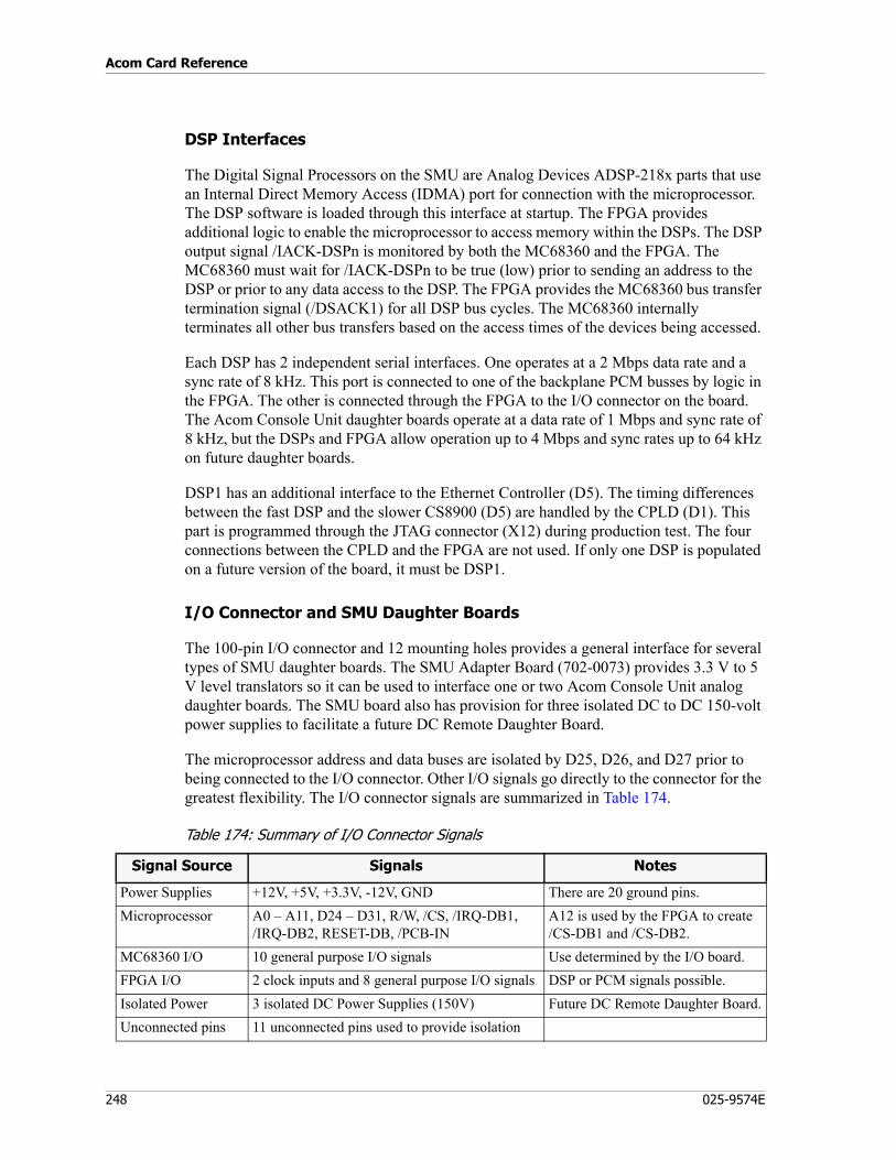
Acom Card Reference
248 025-9574E
DSP Interfaces
The Digital Signal Processors on the SMU are Analog Devices ADSP-218x parts that use an Internal Direct Memory Access (IDMA) port for connection with the microprocessor. The DSP software is loaded through this interface at startup. The FPGA provides additional logic to enable the microprocessor to access memory within the DSPs. The DSP output signal /IACK-DSPn is monitored by both the MC68360 and the FPGA. The MC68360 must wait for /IACK-DSPn to be true (low) prior to sending an address to the DSP or prior to any data access to the DSP. The FPGA provides the MC68360 bus transfer termination signal (/DSACK1) for all DSP bus cycles. The MC68360 internally terminates all other bus transfers based on the access times of the devices being accessed.
Each DSP has 2 independent serial interfaces. One operates at a 2 Mbps data rate and a sync rate of 8 kHz. This port is connected to one of the backplane PCM busses by logic in the FPGA. The other is connected through the FPGA to the I/O connector on the board. The Acom Console Unit daughter boards operate at a data rate of 1 Mbps and sync rate of 8 kHz, but the DSPs and FPGA allow operation up to 4 Mbps and sync rates up to 64 kHz on future daughter boards.
DSP1 has an additional interface to the Ethernet Controller (D5). The timing differences between the fast DSP and the slower CS8900 (D5) are handled by the CPLD (D1). This part is programmed through the JTAG connector (X12) during production test. The four connections between the CPLD and the FPGA are not used. If only one DSP is populated on a future version of the board, it must be DSP1.
I/O Connector and SMU Daughter Boards
The 100-pin I/O connector and 12 mounting holes provides a general interface for several types of SMU daughter boards. The SMU Adapter Board (702-0073) provides 3.3 V to 5 V level translators so it can be used to interface one or two Acom Console Unit analog daughter boards. The SMU board also has provision for three isolated DC to DC 150-volt power supplies to facilitate a future DC Remote Daughter Board.
The microprocessor address and data buses are isolated by D25, D26, and D27 prior to being connected to the I/O connector. Other I/O signals go directly to the connector for the greatest flexibility. The I/O connector signals are summarized in Table 174.
Table 174: Summary of I/O Connector Signals
Signal Source Signals Notes
Power Supplies +12V, +5V, +3.3V, -12V, GND There are 20 ground pins.Microprocessor A0 – A11, D24 – D31, R/W, /CS, /IRQ-DB1,
/IRQ-DB2, RESET-DB, /PCB-INA12 is used by the FPGA to create /CS-DB1 and /CS-DB2.
MC68360 I/O 10 general purpose I/O signals Use determined by the I/O board.FPGA I/O 2 clock inputs and 8 general purpose I/O signals DSP or PCM signals possible.Isolated Power 3 isolated DC Power Supplies (150V) Future DC Remote Daughter Board.Unconnected pins 11 unconnected pins used to provide isolation
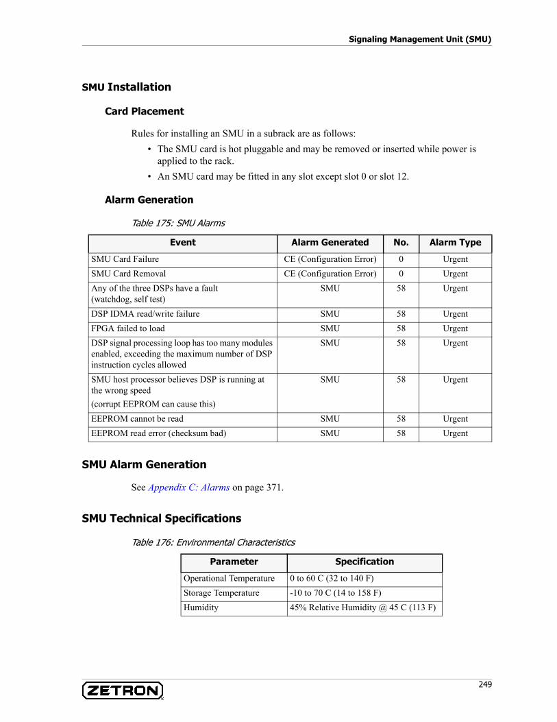
249
Signaling Management Unit (SMU)
SMU Installation
Card Placement
Rules for installing an SMU in a subrack are as follows:• The SMU card is hot pluggable and may be removed or inserted while power is
applied to the rack.• An SMU card may be fitted in any slot except slot 0 or slot 12.
Alarm Generation
Table 175: SMU Alarms
SMU Alarm Generation
See Appendix C: Alarms on page 371.
SMU Technical Specifications
Table 176: Environmental Characteristics
Event Alarm Generated No. Alarm Type
SMU Card Failure CE (Configuration Error) 0 UrgentSMU Card Removal CE (Configuration Error) 0 UrgentAny of the three DSPs have a fault(watchdog, self test)
SMU 58 Urgent
DSP IDMA read/write failure SMU 58 UrgentFPGA failed to load SMU 58 UrgentDSP signal processing loop has too many modules enabled, exceeding the maximum number of DSP instruction cycles allowed
SMU 58 Urgent
SMU host processor believes DSP is running at the wrong speed(corrupt EEPROM can cause this)
SMU 58 Urgent
EEPROM cannot be read SMU 58 UrgentEEPROM read error (checksum bad) SMU 58 Urgent
Parameter Specification
Operational Temperature 0 to 60 C (32 to 140 F)Storage Temperature -10 to 70 C (14 to 158 F)Humidity 45% Relative Humidity @ 45 C (113 F)
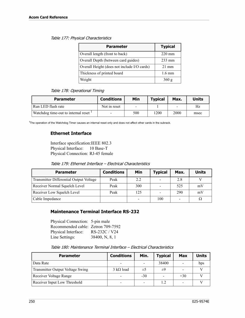
Acom Card Reference
250 025-9574E
Table 177: Physical Characteristics
Table 178: Operational Timing
1The operation of the Watchdog Timer causes an internal reset only and does not affect other cards in the subrack.
Ethernet Interface
Interface specification:IEEE 802.3Physical Interface: 10 Base-TPhysical Connection: RJ-45 female
Table 179: Ethernet Interface – Electrical Characteristics
Maintenance Terminal Interface RS-232
Physical Connection: 5-pin maleRecommended cable: Zetron 709-7592Physical Interface: RS-232C / V24Line Settings: 38400, N, 8, 1
Table 180: Maintenance Terminal Interface – Electrical Characteristics
Parameter Typical
Overall length (front to back) 220 mmOverall Depth (between card guides) 233 mmOverall Height (does not include I/O cards) 21 mmThickness of printed board 1.6 mmWeight 360 g
Parameter Conditions Min Typical Max. Units
Run LED flash rate Not in reset - 1 - HzWatchdog time-out to internal reset 1 - 500 1200 2000 msec
Parameter Conditions Min Typical Max. Units
Transmitter Differential Output Voltage Peak 2.2 - 2.8 VReceiver Normal Squelch Level Peak 300 - 525 mVReceiver Low Squelch Level Peak 125 - 290 mVCable Impedance - 100 - Ω
Parameter Conditions Min. Typical Max Units
Data Rate - - 38400 - bpsTransmitter Output Voltage Swing 3 kΩ load ±5 ±9 - VReceiver Voltage Range - -30 - +30 VReceiver Input Low Threshold - - 1.2 - V
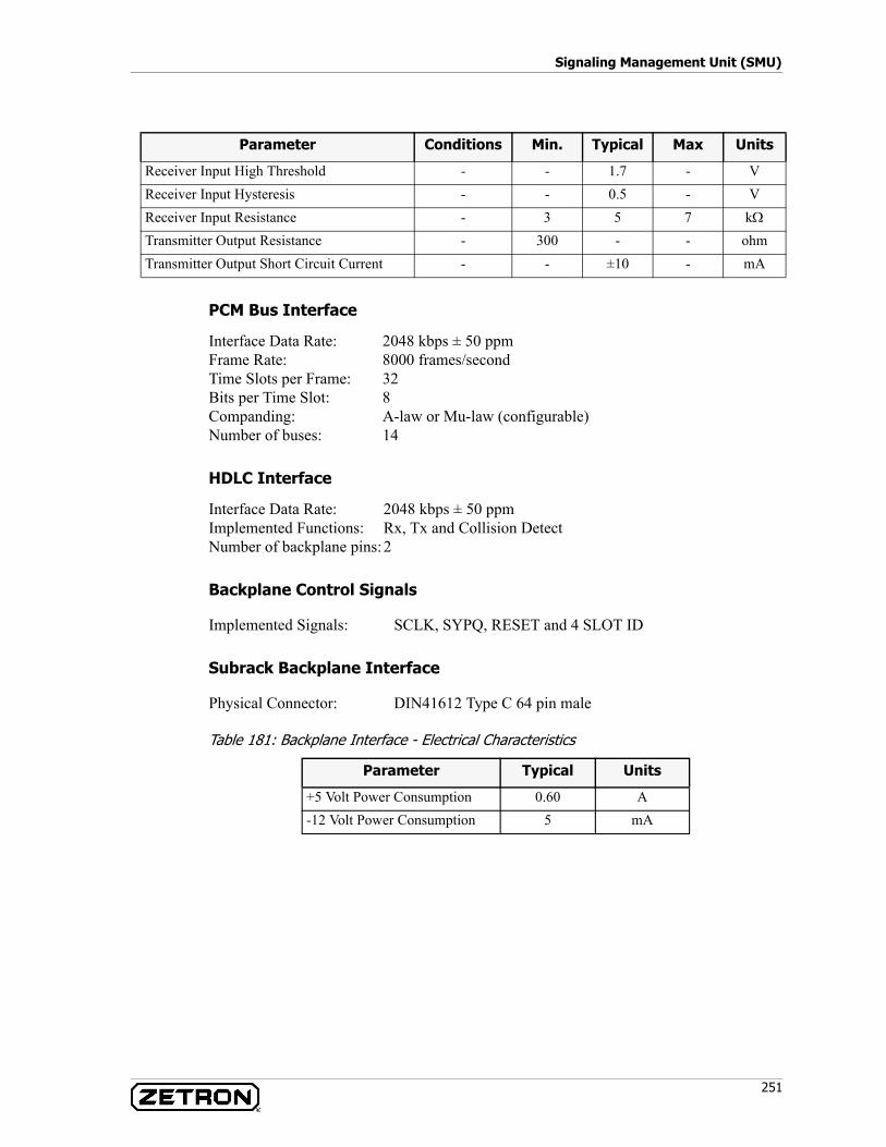
251
Signaling Management Unit (SMU)
PCM Bus Interface
Interface Data Rate: 2048 kbps ± 50 ppmFrame Rate: 8000 frames/secondTime Slots per Frame: 32Bits per Time Slot: 8Companding: A-law or Mu-law (configurable)Number of buses: 14
HDLC Interface
Interface Data Rate: 2048 kbps ± 50 ppmImplemented Functions: Rx, Tx and Collision DetectNumber of backplane pins:2
Backplane Control Signals
Implemented Signals: SCLK, SYPQ, RESET and 4 SLOT ID
Subrack Backplane Interface
Physical Connector: DIN41612 Type C 64 pin male
Table 181: Backplane Interface - Electrical Characteristics
Receiver Input High Threshold - - 1.7 - VReceiver Input Hysteresis - - 0.5 - VReceiver Input Resistance - 3 5 7 kΩ
Transmitter Output Resistance - 300 - - ohmTransmitter Output Short Circuit Current - - ±10 - mA
Parameter Conditions Min. Typical Max Units
Parameter Typical Units
+5 Volt Power Consumption 0.60 A-12 Volt Power Consumption 5 mA
Acom Card Reference
252 025-9574E
Telephone Interface Unit (TIE)
P/N 950-0483 (Australia)P/N 950-0591 (USA)
The TIE is a line card that provides a data path from the six 2-wire audio interfaces on the front of the card to other cards through the backplane data bus. It provides an interface between external subscriber telephone equipment and a communications system that can handle all ringing and telephone line-state detection such as ring out/loop in signaling.
The TIE has six independent 2-wire telephone channels. Each channel has the following features:
• 600Ω or complex line termination• Battery voltage feed• Loop detection• Decadic dialing detection• Ring signal output (requires an RGU card in the subrack)• Earth Recall Signal detection• Line Break detection• Allows CLI to be passed transparently• 300 to 3400 Hz channel bandwidth• Line isolation
The channel gain can be set using the IMS software package.
TIE Block Diagram
Figure 88 shows the major functional blocks of the TIE. Table 182 describes each of these blocks in detail.

253
Telephone Interface Unit (TIE)
Figure 88: TIE Functional Block Diagram
Description of TIE Functional Blocks
Table 182: Description of TIE Functional Blocks
Codec 1/2
Microprocessor System
BackplaneConnector
Note: For clarity, only one of six channels is shown
ResetCircuit
LA
LB
Microprocessor Bus
Line Relay
+12 +5
-12
Power Filters& Regulation
FactoryTest
Interface
Hybrid
RingTrip
Detect
LineProtection
LoopDetect
BatteryFeed
Ring Voltage+ VBat
Line BreakSwitch
Block Description
Line Protection A surge suppression circuit comprising MOVs and inductors.Line Relay When the MCU activates a signaling bit to the TIE, the TIE uses a relay to
disconnect the line from the audio circuits and connect it to the ring voltage. A signaling bit from the Primary MCU controls the relay.
Line Break Switch The line break switch is controlled by a signaling bit from the Primary MCU and opens the lines so that no ring voltage or audio is connected.
Battery Feed Provides a DC battery voltage from the TIE to the line and appears as a high impedance AC.
Loop Detect Consists of detection circuits for positive and negative flow of battery voltage into the line. If either LA or LB is connected to ground, then the Loop Detect circuit allows the TIE to detect an Earth Recall Signal. Signaling bits indicating the status of the loop (i.e., loop detect and Earth Recall) are sent to the Primary MCU.
Hybrid A transformer and electronic circuit are used to provide line impedance of either 600Ω or Complex.
Ring Trip Detection
This circuit is used to detect a phone going off-hook when the TIE is ringing out. When activated, the Microprocessor disconnects the ring voltage by deactivating the Line Relay.
Acom Card Reference
254 025-9574E
TIE Interfaces
The TIE card interfaces can be connected to analog telephone line or to an EIE card interface. These interfaces are used to pass audio and ring voltage. The status of the lines is detected and the associated signaling such as ringing and loop detection are generated.
CODECs perform amplification and analog-to-digital conversion of the audio signals, which allows the gain of each channel to be programmed (using the IMS software package). Transmit and receive signals in excess of the maximum instantaneous input levels may be subject to clipping. When the transmit and receive gains are set to 0 dB, the insertion loss on both the transmit and receive paths is 0 dB.
When the TIE is installed in a subrack with an RGU card, the ring voltage generated by the RGU is used as the TIE ring signal. A TIE will function in a subrack without an RGU card, but there will be no ring voltage available at the TIE interface during ringing.
Signaling
The four types of signals used to control and monitor the status of the TIE interfaces are the following:
• Ring• Line break• Loop detect• Earth recall
Front Edge Layout
Figure 89 shows the front edge layout of the TIE card.
CODEC The CODEC performs the analog-to-digital conversion of the audio signal. The digitized audio and the signaling bits are transmitted to and received from the MCU through the backplane.Each TIE channel uses one half of a CODEC, and there is a total of three CODECs on the TIE.
Microprocessor System
The Microprocessor system combines a CPU, memory, watchdog timer and reset circuitry to provide overall management of the TIE. A factory test interface is provided at connector J15.
Reset Circuit The backplane reset line is connected to circuitry that resets the TIE when the subrack is reset or when the TIE is powered up.
Power Circuit Includes filtering, over voltage protection and soft start circuits to limit the inrush current at power up.
Backplane Connector
A DIN41612 type connector that carries signals for power, data, timing and card detection.
Block Description
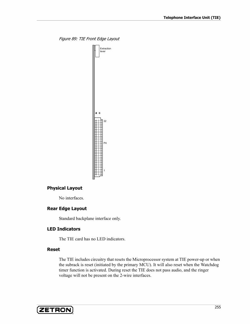
255
Telephone Interface Unit (TIE)
Figure 89: TIE Front Edge Layout
Physical Layout
No interfaces.
Rear Edge Layout
Standard backplane interface only.
LED Indicators
The TIE card has no LED indicators.
Reset
The TIE includes circuitry that resets the Microprocessor system at TIE power-up or when the subrack is reset (initiated by the primary MCU). It will also reset when the Watchdog timer function is activated. During reset the TIE does not pass audio, and the ringer voltage will not be present on the 2-wire interfaces.
a c
32
P4
1
Extractionlever
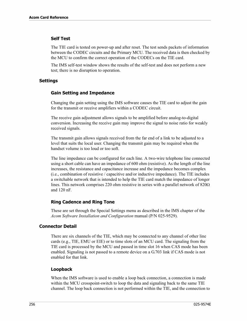
Acom Card Reference
256 025-9574E
Self Test
The TIE card is tested on power-up and after reset. The test sends packets of information between the CODEC circuits and the Primary MCU. The received data is then checked by the MCU to confirm the correct operation of the CODECs on the TIE card.The IMS self-test window shows the results of the self-test and does not perform a new test; there is no disruption to operation.
Settings
Gain Setting and Impedance
Changing the gain setting using the IMS software causes the TIE card to adjust the gain for the transmit or receive amplifiers within a CODEC circuit.
The receive gain adjustment allows signals to be amplified before analog-to-digital conversion. Increasing the receive gain may improve the signal to noise ratio for weakly received signals.
The transmit gain allows signals received from the far end of a link to be adjusted to a level that suits the local user. Changing the transmit gain may be required when the handset volume is too loud or too soft.
The line impedance can be configured for each line. A two-wire telephone line connected using a short cable can have an impedance of 600 ohm (resistive). As the length of the line increases, the resistance and capacitance increase and the impedance becomes complex (i.e., combination of resistive / capacitive and/or inductive impedance). The TIE includes a switchable network that is intended to help the TIE card match the impedance of longer lines. This network comprises 220 ohm resistive in series with a parallel network of 820Ω and 120 nF.
Ring Cadence and Ring Tone
These are set through the Special Settings menu as described in the IMS chapter of the Acom Software Installation and Configuration manual (P/N 025-9529).
Connector Detail
There are six channels of the TIE, which may be connected to any channel of other line cards (e.g., TIE, EMU or EIE) or to time slots of an MCU card. The signaling from the TIE card is processed by the MCU and passed in time slot 16 when CAS mode has been enabled. Signaling is not passed to a remote device on a G.703 link if CAS mode is not enabled for that link.
Loopback
When the IMS software is used to enable a loop back connection, a connection is made within the MCU crosspoint-switch to loop the data and signaling back to the same TIE channel. The loop back connection is not performed within the TIE, and the connection to
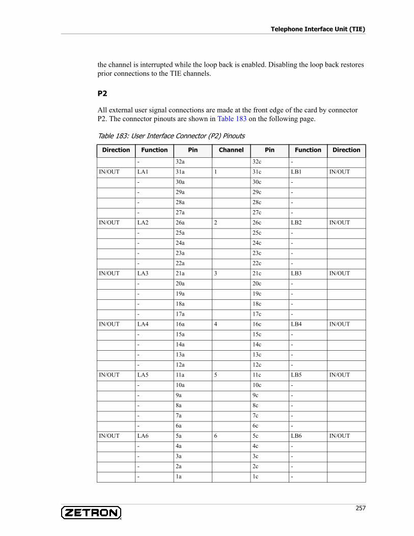
257
Telephone Interface Unit (TIE)
the channel is interrupted while the loop back is enabled. Disabling the loop back restores prior connections to the TIE channels.
P2
All external user signal connections are made at the front edge of the card by connector P2. The connector pinouts are shown in Table 183 on the following page.
Table 183: User Interface Connector (P2) Pinouts
Direction Function Pin Channel Pin Function Direction
- 32a 32c -
IN/OUT LA1 31a 1 31c LB1 IN/OUT
- 30a 30c -
- 29a 29c -
- 28a 28c -
- 27a 27c -
IN/OUT LA2 26a 2 26c LB2 IN/OUT
- 25a 25c -
- 24a 24c -
- 23a 23c -
- 22a 22c -
IN/OUT LA3 21a 3 21c LB3 IN/OUT
- 20a 20c -
- 19a 19c -
- 18a 18c -
- 17a 17c -
IN/OUT LA4 16a 4 16c LB4 IN/OUT
- 15a 15c -
- 14a 14c -
- 13a 13c -
- 12a 12c -
IN/OUT LA5 11a 5 11c LB5 IN/OUT
- 10a 10c -
- 9a 9c -
- 8a 8c -
- 7a 7c -
- 6a 6c -
IN/OUT LA6 5a 6 5c LB6 IN/OUT
- 4a 4c -
- 3a 3c -
- 2a 2c -
- 1a 1c -
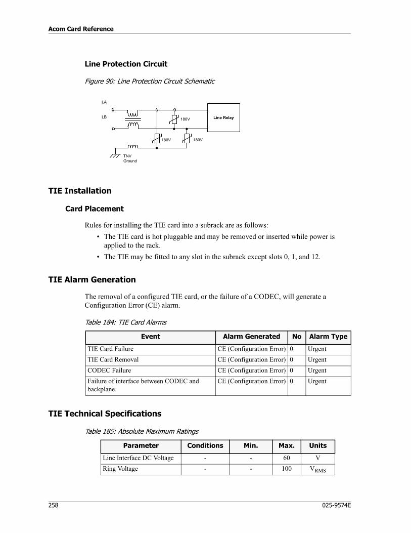
Acom Card Reference
258 025-9574E
Line Protection Circuit
Figure 90: Line Protection Circuit Schematic
TIE Installation
Card Placement
Rules for installing the TIE card into a subrack are as follows:• The TIE card is hot pluggable and may be removed or inserted while power is
applied to the rack. • The TIE may be fitted to any slot in the subrack except slots 0, 1, and 12.
TIE Alarm Generation
The removal of a configured TIE card, or the failure of a CODEC, will generate a Configuration Error (CE) alarm.
Table 184: TIE Card Alarms
TIE Technical Specifications
Table 185: Absolute Maximum Ratings
LA
LB
180V 180V
TNVGround
Line Relay180V
.
.
Event Alarm Generated No Alarm Type
TIE Card Failure CE (Configuration Error) 0 UrgentTIE Card Removal CE (Configuration Error) 0 UrgentCODEC Failure CE (Configuration Error) 0 UrgentFailure of interface between CODEC and backplane.
CE (Configuration Error) 0 Urgent
Parameter Conditions Min. Max. Units
Line Interface DC Voltage - - 60 VRing Voltage - - 100 VRMS
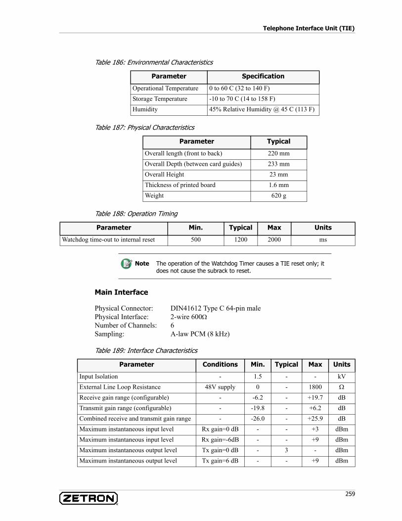
259
Telephone Interface Unit (TIE)
Table 186: Environmental Characteristics
Table 187: Physical Characteristics
Table 188: Operation Timing
Main Interface
Physical Connector: DIN41612 Type C 64-pin malePhysical Interface: 2-wire 600ΩNumber of Channels: 6Sampling: A-law PCM (8 kHz)
Table 189: Interface Characteristics
Parameter Specification
Operational Temperature 0 to 60 C (32 to 140 F)Storage Temperature -10 to 70 C (14 to 158 F)Humidity 45% Relative Humidity @ 45 C (113 F)
Parameter Typical
Overall length (front to back) 220 mmOverall Depth (between card guides) 233 mmOverall Height 23 mmThickness of printed board 1.6 mmWeight 620 g
Parameter Min. Typical Max Units
Watchdog time-out to internal reset 500 1200 2000 ms
Note The operation of the Watchdog Timer causes a TIE reset only; it does not cause the subrack to reset.
Parameter Conditions Min. Typical Max Units
Input Isolation - 1.5 - - kVExternal Line Loop Resistance 48V supply 0 - 1800 Ω
Receive gain range (configurable) - -6.2 - +19.7 dBTransmit gain range (configurable) - -19.8 - +6.2 dBCombined receive and transmit gain range - -26.0 - +25.9 dBMaximum instantaneous input level Rx gain=0 dB - - +3 dBmMaximum instantaneous input level Rx gain=-6dB - - +9 dBmMaximum instantaneous output level Tx gain=0 dB - 3 - dBmMaximum instantaneous output level Tx gain=6 dB - - +9 dBm

Acom Card Reference
260 025-9574E
Subrack Backplane Interface
Physical Connector: DIN41612 Type C 64-pin male
Table 190: Electrical Characteristics
Electromagnetic Compatibility
Compliant to AS3548 Class A and FCC Part 15, Class A.
Universal Input/Output (UIO)
P/N 950-0490
The Universal Input/Output (UIO) system card provides connections from the channel interfaces to the primary MCU by the backplane data bus. The card provides an interface between external equipment requiring discrete contact closure signals and a communications system.
Frequency response - 300 - 3400 HzVariation of gain with level 0.3 - 2.4 kHz -0.5 - +0.5 dBVariation of gain with level 0.3 - 3.4 kHz -0.5 - +1.8 dBSignal to total distortion 1020 Hz 33 - - dBReturn loss 0.3 - 3.4 kHz 20 - - dBChannel to channel cross talk - - - -66 dB
Parameter Conditions Min. Typical Max Units
Parameter Max Units
-12 Volt TNV Power Consumption 71 mA+5 Volt Power Consumption 120 mA+12 Volt Power Consumption 5 mA-12 Volt Power Consumption 59 mA
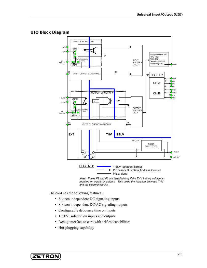
261
Universal Input/Output (UIO)
UIO Block Diagram
The card has the following features:• Sixteen independent DC signaling inputs• Sixteen independent DC/AC signaling outputs• Configurable debounce time on inputs• 1.5 kV isolation on inputs and outputs• Debug interface to card with selftest capabilities• Hot-plugging capability
OUTPUT COMMONBUS
TNV_-12V
OUTA1
OUTC1
INPUT COMMONBUS
INA1
INC1
JMP1A..F
JMP19
JMP3
JMP2
15
30
30
15
INPUT CIRCUIT CH1
OUTPUT CIRCUIT CH1
DC-DCCONVERTER
OUTPUTBUFFERSU8,U9
INPUTBUFFERSU10,U11
Microprocessor (U1)ROM (U2)RAM (U3)Decoding (U4,U5)WatchDog (U6)
HDLC U7INPUT CIRCUITS CH2-CH16
OUTPUT CIRCUITS CH2-CH16
RLY1
+VE_BAT
-VE_BAT
F2
F3
LEGEND: 1.5KV Isolation BarrierProcessor Bus:Data,Address,ControlMisc. signal
DCLK
FSC
DU1
DD1
SCLK
SYPQ
CTX
CRX
CH B
CH A
RESET
EXT TNV SELV
P5PINS 1&3
P5PINS 2&4
Note: Fuses F2 and F3 are installed only if the TNV battery voltage isrequired on inputs or outputs. This voids the isolation between TNVand the external circuits.
Acom Card Reference
262 025-9574E
Description of Major Functional Blocks
The following describes the major functional blocks illustrated in the above diagram.
Input Interface
The input interface is comprised of 16 identical circuits providing polarity and independent conversion of DC signaling inputs to opto isolated logic inputs. The rectified output from the bridge is then conditioned by the circuitry comprised of Q1, R1, R2, D1, and D2. This circuit configuration provides a constant current drive for the opto-coupler diode of nominally 1.5 mA over most of the input voltage range. Capacitor C1 across the rectifier input is for RF suppression, and varistor V1 is for transient over voltage protection. The isolated opto coupler logic output from device U12 is buffered from the system data bus by an octal latch, U10.
Output Interface
The output interface is comprised of 16 identical circuits providing opto-isolated discrete contact closure outputs.
The opto-isolated logic control device U16 performs the contact changeover, switching the TNV-12V to the relay coil. Diode D33 provides back EMF protection of the photo-transistor. No on-board protection against over current or short circuit is provided.
Microcontroller Section
The microcontroller section employs a 647180 microprocessor and 128K each of flash ROM and static RAM.
HDLC Section
The HDLC controller U7 handles backplane communications to and from the primary MCU. All signals to and from the backplane are buffered by ABT devices for hot plugging.
DC-DC Converter
Deriving its output from the isolated TNV battery voltage, this circuit provides a nominal 12 VDC output for the relay coils. The circuit is based around the LT1172HVCT device U27 and is capable of operating over a supply range of -20 to -63 VDC.
UIO Interfaces
Front Edge Layout

263
Universal Input/Output (UIO)
Figure 91: Front Layout for UIO card
Physical Layout
No interfaces.
Rear Edge Layout
Standard backplane interface only.
LED Indicators
A single green LED is provided on the front edge of the card (see Figure 91). This is the 'RUN' LED, and it flashes approximately once per second indicating normal operation.
Reset
There is no mechanism for reset.
C32 (INC1)(INA1)A32
(OUTA16)A32 C32 (OUTC16)
P2
DEBUG PORT
P5
Run LED
Extractionlever
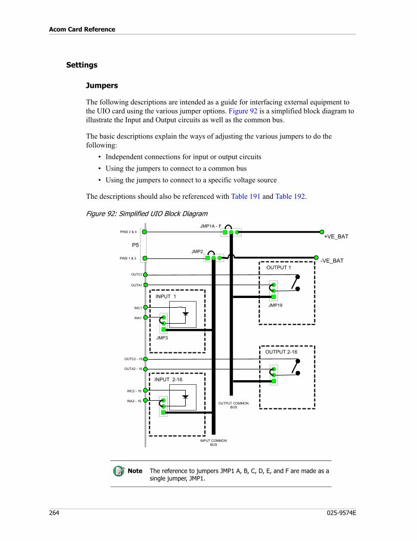
Acom Card Reference
264 025-9574E
Settings
Jumpers
The following descriptions are intended as a guide for interfacing external equipment to the UIO card using the various jumper options. Figure 92 is a simplified block diagram to illustrate the Input and Output circuits as well as the common bus.
The basic descriptions explain the ways of adjusting the various jumpers to do the following:
• Independent connections for input or output circuits• Using the jumpers to connect to a common bus• Using the jumpers to connect to a specific voltage source
The descriptions should also be referenced with Table 191 and Table 192.
Figure 92: Simplified UIO Block Diagram
INPUT COMMONBUS
INA1
INC1
JMP3
INPUT 1
INA2 - 16
INC2 - 16
OUTPUT COMMONBUS
-VE_BAT
+VE_BAT
INPUT 2-16
OUTA1
OUTC1
JMP19
OUTPUT 1
OUTA2 - 16
OUTC2 - 16
OUTPUT 2-16
P5JMP2
JMP1A - F
PINS 1 & 3
PINS 2 & 4
Note The reference to jumpers JMP1 A, B, C, D, E, and F are made as a single jumper, JMP1.
265
Universal Input/Output (UIO)
• The default settings for the jumpers on the UIO have all the inputs and outputs floating; i.e., all channel connections are independent of one another. Under these conditions, use of the card requires that all input and output channels be wired out from connector P2 as individual pairs.
• Any one or more of the input and output channels may be assigned to a common input and output bus respectively. This is handled by the jumper associated with the particular channel(s) located immediately behind the front-plane connector P2. This may be a desirable option where independence of channels is not a concern since the wiring requirements for P2 can be reduced.
• The options regarding the use of the common input and output busses depend on the jumpers JMP2 and JMP1 respectively. Each common bus may be extended out onto connector P5 or referenced to the TNV supply (Figure 92): TNV_-VE_BAT in the case of the common input bus, and TNV_+VE_BAT in the case of the common output bus.
• Under some circumstances it may be desirable to reference both common busses to the same voltage, most likely user ground. No provision exists on the UIO for the two common busses to be tied together. This must be done externally.
• Jumpers JMP35 and JMP36 are zero ohm links. They are used ONLY in the event of the card being used in a subrack having a single upper backplane. Such an installation will void the SELV-TNV isolation.
• Jumpers JMP37 and JMP38 are not used.• Jumpers JMP3 to JMP18 are associated with the 16 input channels. They allow one
input leg to be extended out onto the front-plane connector P2. This is done by either strapping between pins 2-3 or by strapping between pins 1-2 connected to the common input bus (INCOM).
• Jumpers JMP19 to JMP34 are associated with the 16 output channels. They allow one output to be extended out onto the front-plane connector P2. This is done by either strapping between pins 2-3 or by strapping between 1-2 connected to the common output bus (OUTCOM).
• Jumper JMP2 extends the common input bus (INCOM) to either pin 1 or 3 on the front-plane connector P5 by strapping pins 1-2, or referencing JMP2 to -VE_BAT by strapping pins 2-3.
• Jumpers JMP1 A, B, C, D, E, and F extend the common output bus (OUTCOM) to either pins 2 and 4 on front-plane connector P5 by strapping pins 1-2, or references
Warning! If the full 2 amp rating of all outputs is a requirement, the individual outputs must be used (default). Otherwise, use of the common output bus is limited to the total current drawn to 12 amp if connected through P5, or 4 amp if referenced to the TNV supply by the F2.
Since no protection against over current or short circuit conditions is provided on the UIO outputs, it is the responsibility of the user to ensure that adequate protection is provided within the external interface.
STOP
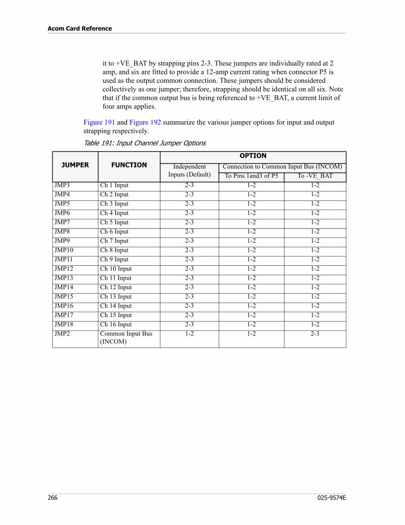
Acom Card Reference
266 025-9574E
it to +VE_BAT by strapping pins 2-3. These jumpers are individually rated at 2 amp, and six are fitted to provide a 12-amp current rating when connector P5 is used as the output common connection. These jumpers should be considered collectively as one jumper; therefore, strapping should be identical on all six. Note that if the common output bus is being referenced to +VE_BAT, a current limit of four amps applies.
Figure 191 and Figure 192 summarize the various jumper options for input and output strapping respectively.
Table 191: Input Channel Jumper Options
JUMPER FUNCTIONOPTION
IndependentInputs (Default)
Connection to Common Input Bus (INCOM)To Pins 1and3 of P5 To -VE_BAT
JMP3 Ch 1 Input 2-3 1-2 1-2JMP4 Ch 2 Input 2-3 1-2 1-2JMP5 Ch 3 Input 2-3 1-2 1-2JMP6 Ch 4 Input 2-3 1-2 1-2JMP7 Ch 5 Input 2-3 1-2 1-2JMP8 Ch 6 Input 2-3 1-2 1-2JMP9 Ch 7 Input 2-3 1-2 1-2JMP10 Ch 8 Input 2-3 1-2 1-2JMP11 Ch 9 Input 2-3 1-2 1-2JMP12 Ch 10 Input 2-3 1-2 1-2JMP13 Ch 11 Input 2-3 1-2 1-2JMP14 Ch 12 Input 2-3 1-2 1-2JMP15 Ch 13 Input 2-3 1-2 1-2JMP16 Ch 14 Input 2-3 1-2 1-2JMP17 Ch 15 Input 2-3 1-2 1-2JMP18 Ch 16 Input 2-3 1-2 1-2JMP2 Common Input Bus
(INCOM)1-2 1-2 2-3
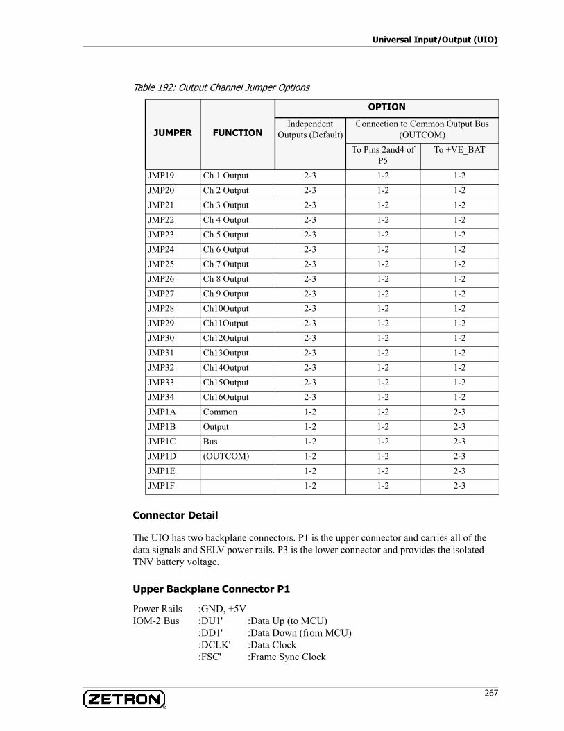
267
Universal Input/Output (UIO)
Table 192: Output Channel Jumper Options
Connector Detail
The UIO has two backplane connectors. P1 is the upper connector and carries all of the data signals and SELV power rails. P3 is the lower connector and provides the isolated TNV battery voltage.
Upper Backplane Connector P1
Power Rails :GND, +5VIOM-2 Bus :DU1' :Data Up (to MCU)
:DD1' :Data Down (from MCU):DCLK' :Data Clock:FSC' :Frame Sync Clock
JUMPER FUNCTION
OPTION
IndependentOutputs (Default)
Connection to Common Output Bus (OUTCOM)
To Pins 2and4 of P5
To +VE_BAT
JMP19 Ch 1 Output 2-3 1-2 1-2JMP20 Ch 2 Output 2-3 1-2 1-2JMP21 Ch 3 Output 2-3 1-2 1-2JMP22 Ch 4 Output 2-3 1-2 1-2JMP23 Ch 5 Output 2-3 1-2 1-2JMP24 Ch 6 Output 2-3 1-2 1-2JMP25 Ch 7 Output 2-3 1-2 1-2JMP26 Ch 8 Output 2-3 1-2 1-2JMP27 Ch 9 Output 2-3 1-2 1-2JMP28 Ch10Output 2-3 1-2 1-2JMP29 Ch11Output 2-3 1-2 1-2JMP30 Ch12Output 2-3 1-2 1-2JMP31 Ch13Output 2-3 1-2 1-2JMP32 Ch14Output 2-3 1-2 1-2JMP33 Ch15Output 2-3 1-2 1-2JMP34 Ch16Output 2-3 1-2 1-2JMP1A Common 1-2 1-2 2-3JMP1B Output 1-2 1-2 2-3JMP1C Bus 1-2 1-2 2-3JMP1D (OUTCOM) 1-2 1-2 2-3JMP1E 1-2 1-2 2-3JMP1F 1-2 1-2 2-3
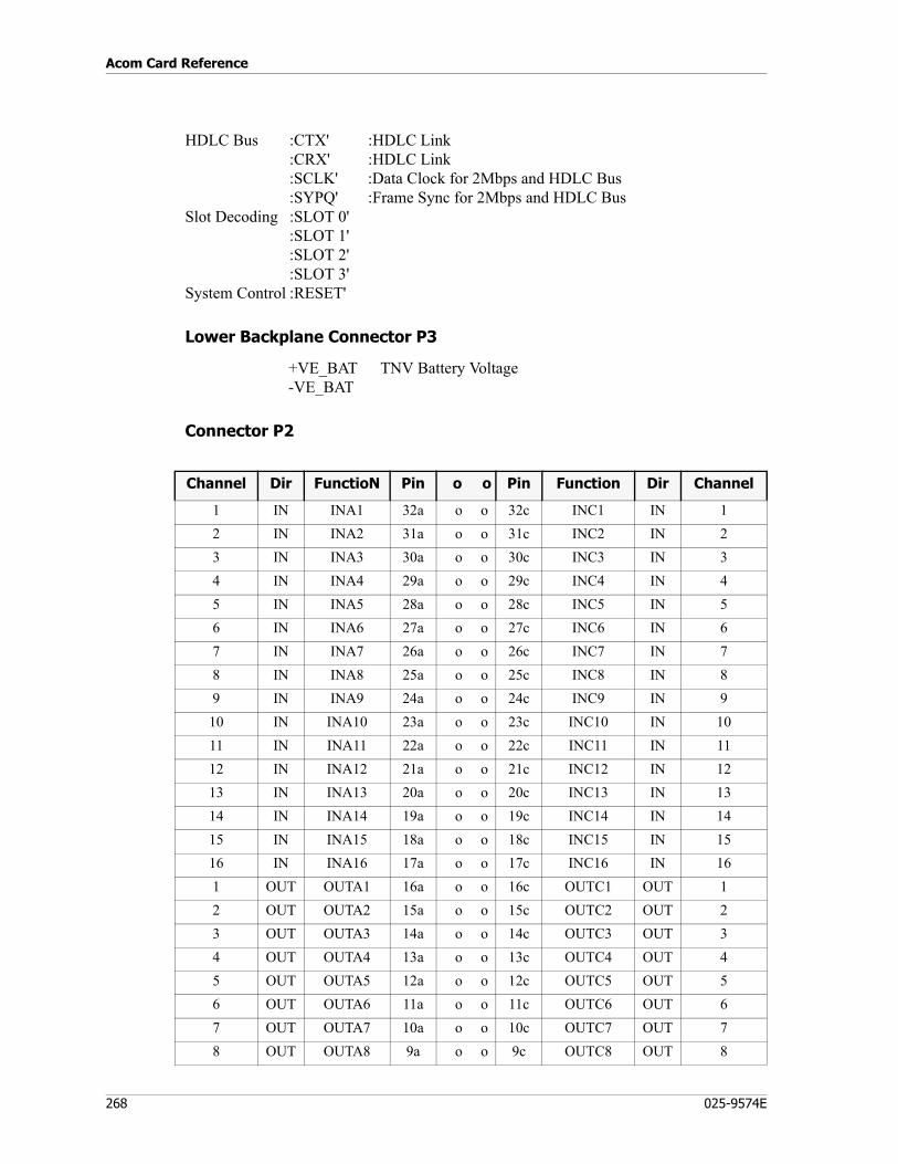
Acom Card Reference
268 025-9574E
HDLC Bus :CTX' :HDLC Link:CRX' :HDLC Link:SCLK' :Data Clock for 2Mbps and HDLC Bus:SYPQ' :Frame Sync for 2Mbps and HDLC Bus
Slot Decoding :SLOT 0':SLOT 1':SLOT 2':SLOT 3'
System Control :RESET'
Lower Backplane Connector P3
+VE_BAT TNV Battery Voltage-VE_BAT
Connector P2
Channel Dir FunctioN Pin o o Pin Function Dir Channel
1 IN INA1 32a o o 32c INC1 IN 12 IN INA2 31a o o 31c INC2 IN 23 IN INA3 30a o o 30c INC3 IN 34 IN INA4 29a o o 29c INC4 IN 45 IN INA5 28a o o 28c INC5 IN 56 IN INA6 27a o o 27c INC6 IN 67 IN INA7 26a o o 26c INC7 IN 78 IN INA8 25a o o 25c INC8 IN 89 IN INA9 24a o o 24c INC9 IN 910 IN INA10 23a o o 23c INC10 IN 1011 IN INA11 22a o o 22c INC11 IN 1112 IN INA12 21a o o 21c INC12 IN 1213 IN INA13 20a o o 20c INC13 IN 1314 IN INA14 19a o o 19c INC14 IN 1415 IN INA15 18a o o 18c INC15 IN 1516 IN INA16 17a o o 17c INC16 IN 161 OUT OUTA1 16a o o 16c OUTC1 OUT 12 OUT OUTA2 15a o o 15c OUTC2 OUT 23 OUT OUTA3 14a o o 14c OUTC3 OUT 34 OUT OUTA4 13a o o 13c OUTC4 OUT 45 OUT OUTA5 12a o o 12c OUTC5 OUT 56 OUT OUTA6 11a o o 11c OUTC6 OUT 67 OUT OUTA7 10a o o 10c OUTC7 OUT 78 OUT OUTA8 9a o o 9c OUTC8 OUT 8
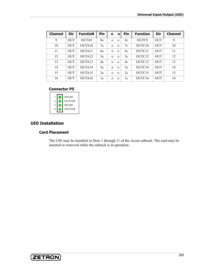
269
Universal Input/Output (UIO)
Connector P5
UIO Installation
Card Placement
The UIO may be installed in Slots 1 through 11 of the Acom subrack. The card may be inserted or removed while the subrack is in operation.
9 OUT OUTA9 8a o o 8c OUTC9 OUT 910 OUT OUTA10 7a o o 7c OUTC10 OUT 1011 OUT OUTA11 6a o o 6c OUTC11 OUT 1112 OUT OUTA12 5a o o 5c OUTC12 OUT 1213 OUT OUTA13 4a o o 4c OUTC13 OUT 1314 OUT OUTA14 3a o o 3c OUTC14 OUT 1415 OUT OUTA15 2a o o 2c OUTC15 OUT 1516 OUT OUTA16 1a o o 1c OUTC16 OUT 16
Channel Dir FunctioN Pin o o Pin Function Dir Channel
OUTCOM1234
INCOM
INCOMOUTCOM
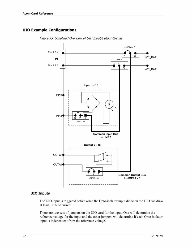
Acom Card Reference
270 025-9574E
UIO Example Configurations
Figure 93: Simplified Overview of UIO Input/Output Circuits
UIO Inputs
The UIO input is triggered active when the Opto-isolator input diode on the UIO can draw at least 1mA of current.
There are two sets of jumpers on the UIO card for the input. One will determine the reference voltage for the input and the other jumpers will determine if each Opto-isolator input is independent from the reference voltage.
1 3 +VE_BATP5
Pins 2 & 4
Pins 1 & 3
JMP1A - F
1 3
JMP2
-VE_BAT
INC1
INA1
JMP3 - 18
3 12
Input x - 16
Common Input Busto JMP2
Output x - 16
3 12 Common Output Busto JMP1A - F
OUTC1
OUTA1
JMP19 - 34
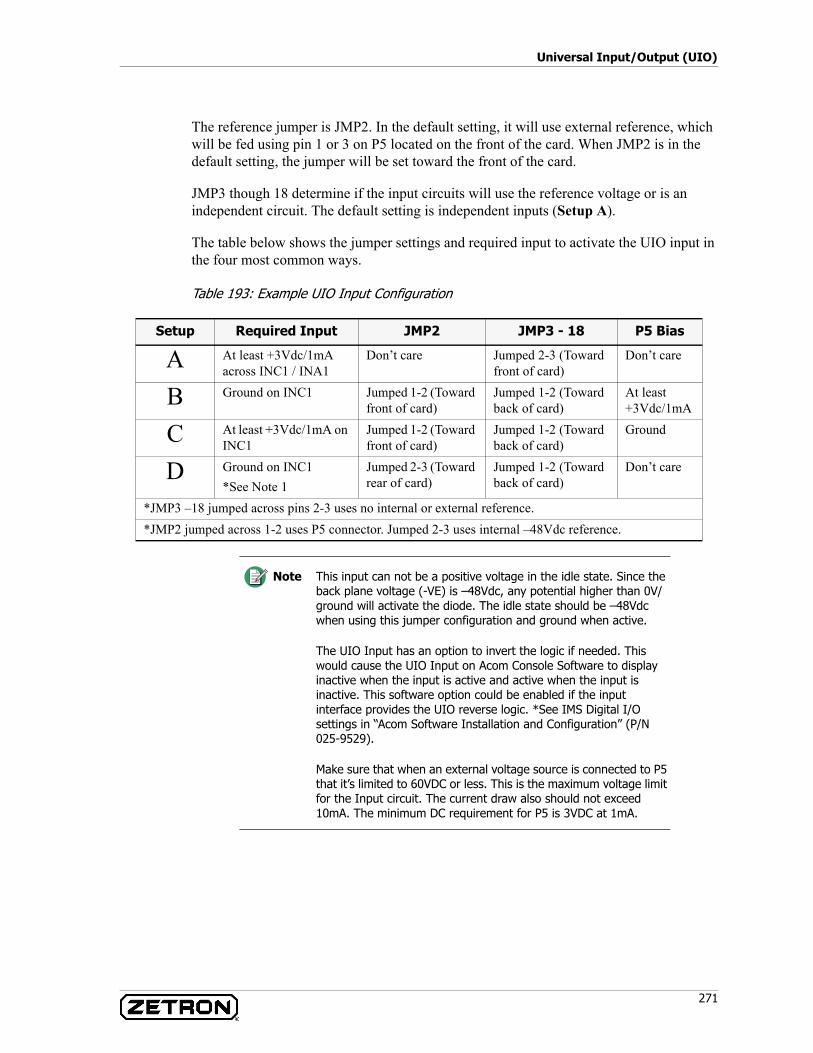
271
Universal Input/Output (UIO)
The reference jumper is JMP2. In the default setting, it will use external reference, which will be fed using pin 1 or 3 on P5 located on the front of the card. When JMP2 is in the default setting, the jumper will be set toward the front of the card.
JMP3 though 18 determine if the input circuits will use the reference voltage or is an independent circuit. The default setting is independent inputs (Setup A).
The table below shows the jumper settings and required input to activate the UIO input in the four most common ways.
Table 193: Example UIO Input Configuration
Setup Required Input JMP2 JMP3 - 18 P5 Bias
A At least +3Vdc/1mA across INC1 / INA1
Don’t care Jumped 2-3 (Toward front of card)
Don’t care
B Ground on INC1 Jumped 1-2 (Toward front of card)
Jumped 1-2 (Toward back of card)
At least +3Vdc/1mA
C At least +3Vdc/1mA on INC1
Jumped 1-2 (Toward front of card)
Jumped 1-2 (Toward back of card)
Ground
D Ground on INC1*See Note 1
Jumped 2-3 (Toward rear of card)
Jumped 1-2 (Toward back of card)
Don’t care
*JMP3 –18 jumped across pins 2-3 uses no internal or external reference.*JMP2 jumped across 1-2 uses P5 connector. Jumped 2-3 uses internal –48Vdc reference.
Note This input can not be a positive voltage in the idle state. Since the back plane voltage (-VE) is –48Vdc, any potential higher than 0V/ground will activate the diode. The idle state should be –48Vdc when using this jumper configuration and ground when active.
The UIO Input has an option to invert the logic if needed. This would cause the UIO Input on Acom Console Software to display inactive when the input is active and active when the input is inactive. This software option could be enabled if the input interface provides the UIO reverse logic. *See IMS Digital I/O settings in “Acom Software Installation and Configuration” (P/N 025-9529).
Make sure that when an external voltage source is connected to P5 that it’s limited to 60VDC or less. This is the maximum voltage limit for the Input circuit. The current draw also should not exceed 10mA. The minimum DC requirement for P5 is 3VDC at 1mA.
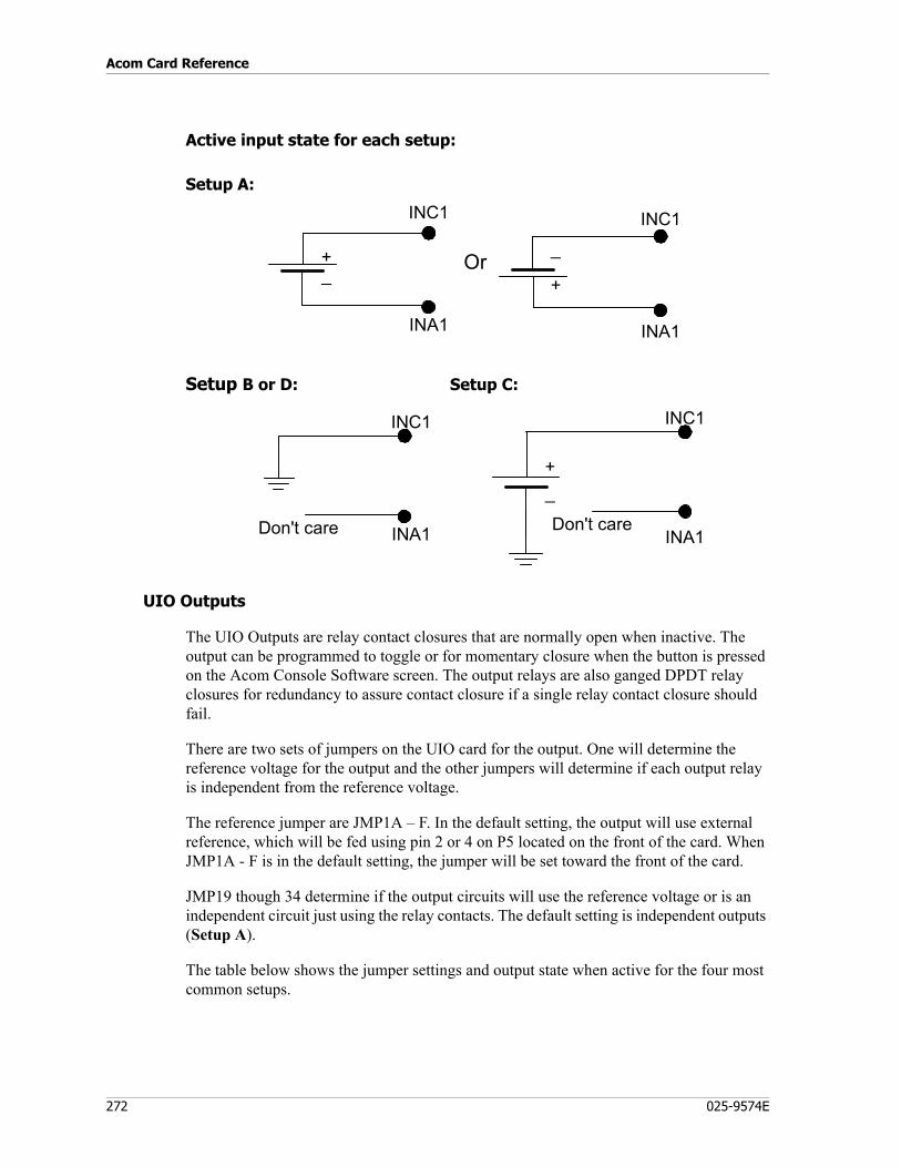
Acom Card Reference
272 025-9574E
Active input state for each setup:
Setup A:
Setup B or D: Setup C:
UIO Outputs
The UIO Outputs are relay contact closures that are normally open when inactive. The output can be programmed to toggle or for momentary closure when the button is pressed on the Acom Console Software screen. The output relays are also ganged DPDT relay closures for redundancy to assure contact closure if a single relay contact closure should fail.
There are two sets of jumpers on the UIO card for the output. One will determine the reference voltage for the output and the other jumpers will determine if each output relay is independent from the reference voltage.
The reference jumper are JMP1A – F. In the default setting, the output will use external reference, which will be fed using pin 2 or 4 on P5 located on the front of the card. When JMP1A - F is in the default setting, the jumper will be set toward the front of the card.
JMP19 though 34 determine if the output circuits will use the reference voltage or is an independent circuit just using the relay contacts. The default setting is independent outputs (Setup A).
The table below shows the jumper settings and output state when active for the four most common setups.
INC1
INA1
Or
INC1
INA1
_+ _
+
INC1
INA1Don't care
INC1
INA1Don't care
_+
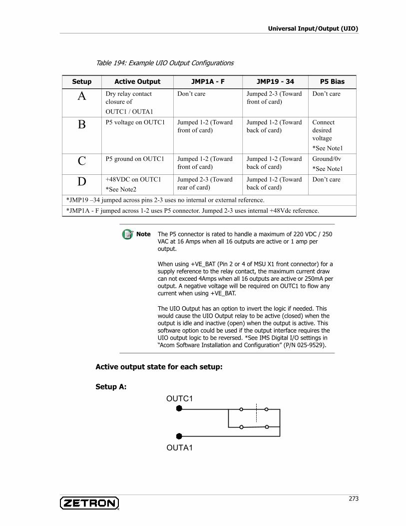
273
Universal Input/Output (UIO)
Table 194: Example UIO Output Configurations
Active output state for each setup:
Setup A:
Setup Active Output JMP1A - F JMP19 - 34 P5 Bias
A Dry relay contact closure of OUTC1 / OUTA1
Don’t care Jumped 2-3 (Toward front of card)
Don’t care
B P5 voltage on OUTC1 Jumped 1-2 (Toward front of card)
Jumped 1-2 (Toward back of card)
Connect desired voltage*See Note1
C P5 ground on OUTC1 Jumped 1-2 (Toward front of card)
Jumped 1-2 (Toward back of card)
Ground/0v*See Note1
D +48VDC on OUTC1*See Note2
Jumped 2-3 (Toward rear of card)
Jumped 1-2 (Toward back of card)
Don’t care
*JMP19 –34 jumped across pins 2-3 uses no internal or external reference.*JMP1A - F jumped across 1-2 uses P5 connector. Jumped 2-3 uses internal +48Vdc reference.
Note The P5 connector is rated to handle a maximum of 220 VDC / 250 VAC at 16 Amps when all 16 outputs are active or 1 amp per output.
When using +VE_BAT (Pin 2 or 4 of MSU X1 front connector) for a supply reference to the relay contact, the maximum current draw can not exceed 4Amps when all 16 outputs are active or 250mA per output. A negative voltage will be required on OUTC1 to flow any current when using +VE_BAT.
The UIO Output has an option to invert the logic if needed. This would cause the UIO Output relay to be active (closed) when the output is idle and inactive (open) when the output is active. This software option could be used if the output interface requires the UIO output logic to be reversed. *See IMS Digital I/O settings in “Acom Software Installation and Configuration” (P/N 025-9529).
OUTC1
OUTA1
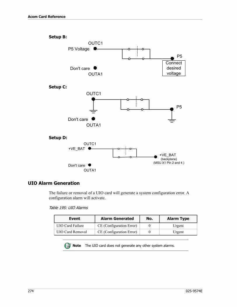
Acom Card Reference
274 025-9574E
Setup B:
Setup C:
Setup D:
UIO Alarm Generation
The failure or removal of a UIO card will generate a system configuration error. A configuration alarm will activate.
Table 195: UIO Alarms
P5
OUTC1
OUTA1Don't care
P5 Voltage
Connectdesiredvoltage
P5
OUTC1
OUTA1Don't care
+VE_BAT
OUTC1
OUTA1Don't care
+VE_BAT
(backplane)(MSU X1 Pin 2 and 4 )
Event Alarm Generated No. Alarm Type
UIO Card Failure CE (Configuration Error) 0 UrgentUIO Card Removal CE (Configuration Error) 0 Urgent
Note The UIO card does not generate any other system alarms.
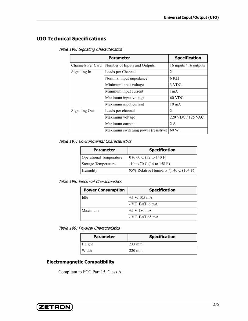
275
Universal Input/Output (UIO)
UIO Technical Specifications
Table 196: Signaling Characteristics
Table 197: Environmental Characteristics
Table 198: Electrical Characteristics
Table 199: Physical Characteristics
Electromagnetic Compatibility
Compliant to FCC Part 15, Class A.
Parameter Specification
Channels Per Card Number of Inputs and Outputs 16 inputs / 16 outputsSignaling In Leads per Channel 2
Nominal input impedance 6 KΩ
Minimum input voltage 3 VDCMinimum input current 1mAMaximum input voltage 60 VDCMaximum input current 10 mA
Signaling Out Leads per channel 2Maximum voltage 220 VDC / 125 VACMaximum current 2 AMaximum switching power (resistive) 60 W
Parameter Specification
Operational Temperature 0 to 60 C (32 to 140 F)Storage Temperature -10 to 70 C (14 to 158 F)Humidity 95% Relative Humidity @ 40 C (104 F)
Power Consumption Specification
Idle +5 V: 105 mA- VE_BAT: 6 mA
Maximum +5 V 180 mA- VE_BAT:65 mA
Parameter Specification
Height 233 mmWidth 220 mm

Acom Card Reference
276 025-9574E
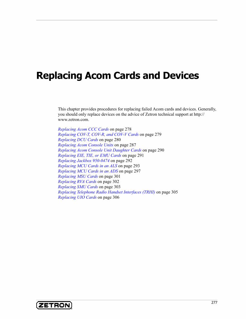
277
Replacing Acom Cards and Devices
This chapter provides procedures for replacing failed Acom cards and devices. Generally, you should only replace devices on the advice of Zetron technical support at http://www.zetron.com.
Replacing Acom CCC Cards on page 278Replacing COV-T, COV-R, and COV-V Cards on page 279Replacing DCU Cards on page 280Replacing Acom Console Units on page 287Replacing Acom Console Unit Daughter Cards on page 290Replacing EIE, TIE, or EMU Cards on page 291Replacing Jackbox 950-0474 on page 292Replacing MCU Cards in an ALS on page 293Replacing MCU Cards in an ADS on page 297Replacing MSU Cards on page 301Replacing RVA Cards on page 302Replacing SMU Cards on page 303Replacing Telephone Radio Handset Interfaces (TRHI) on page 305Replacing UIO Cards on page 306
Replacing Acom Cards and Devices
278 025-9574E
Replacing Acom CCC Cards
The Changeover Control Card (CCC) signals the COV-V, COV-R, and COV-T relay cards to switch from main to standby.
Equipment Required
• Small flat head screwdriver
♦ To remove the CCC card:
1. When removing a CCC card, change the system over to the primary/main (A) side of the system. This will assure that audio/data from the ALS to the demark will remain active and available. From the primary/main ALS force control over to the other ALS:a. Launch IMS Terminal, and login.b. Double click the ALS. From the Tools menu, select Change Over, select the
Manual option and select the ALS NOT in control.c. Verify that the icon in IMS turns blue for the other ALS.d. Select the Automatic option and exit the Change Over menu.
2. Use a grounding wrist strap to prevent ESD damage to the equipment.3. If you are replacing a CCC card, removing all connectors from the front of the
card. Make sure the cables are labeled. If they are not labeled, label them now so they can be properly connected to the replacement card.
4. The DB9 connectors can be removed using the small flat head screwdriver. The orange weidmuller plug can be pulled out if there are wires connected to them. The power plugs can be removed by squeezing the locking latch on the right side of the plug. It may be easier to pull the CCC card out partially to get a good grasp on the connector/latch to remove the plugs.
5. Flip the top lever on card upward to dislodge it from the backplane. Slide card out slowly and carefully.
6. Once all connectors have been removed, remove the CCC card.
Warning! Please exercise electro-static discharge (ESD) precautions when handling all cards.
STOP
Note These cards are HOT SWAPPABLE but removing the CCC will remove power from the ChangeOver Subrack rack backplane and the COV-T, COV-R, or COV-V cards will default to the primary/main (A) side of the system. Although these cards are hot swappable, it is preferable to turn off the power when swapping out any cards in the system.
Subrack programming is not required when replacing these cards.
279
Replacing COV-T, COV-R, and COV-V Cards
7. Place the old card in the ESB bag.
♦ To install the replacement CCC card:
1. Ground yourself with an ESD wrist strap connected to the rack.2. Remove the new card from the ESD bag.3. Align the card with the card guides at the top, then bottom of the slot.4. Slowly and carefully slide the card into the rack.5. Press the card into the rear connector using two hands on the front of the card.6. Connect the cables to the connectors on the front of the card.7. The LED’s on the COV-T, COV-R, or COV-V card should indicate that they are
active on the primary/main (A) side.8. Change the system over to the backup/standby (B) ALS and verify that audio/data
is passed and the COV-T, COV-R, or COV-V indicate they are switched over to backup/standby (B).
9. After you are satisfied that the Backup/Standby (B) rack is functional, change system back over to the Primary/Main (A) rack for normal operation.
Replacing COV-T, COV-R, and COV-V Cards
The COV-T card is fitted with relays that can switch 6 coaxial SMB connections between the main and standby subracks. This card is hot-swappable.
The COV-V and COV-R cards is fitted with relays that can switch 50 conductors (25 pairs) between the main and standby subracks. There is a common connector on the rear of the card for the line interfaces and 2 connections on the front for the main and standby subracks. This card is hot-swappable.
♦ To remove the COV-T, COV-R, or COV-V card:
1. When removing a COV-T/COV-R/COV-V card, any line resources using the card will not be able to get audio/data to the outside world/demark. The ALSs will be transparent to this and will not know but the operators should be aware not to use
Warning! Please exercise electro-static discharge (ESD) precautions when handling all cards.
STOP
Note Although these cards are hot swappable, it is preferable to turn off the power when swapping out any cards in the system.
Subrack programming is not required when replacing these cards.
Replacing Acom Cards and Devices
280 025-9574E
the line resources associated to the card because they will not be available when the card is removed.
2. Use a grounding wrist strap to prevent ESD damage to the equipment.3. Ensure the connectors are labeled so they can be reconnected in the correct order.4. Carefully disconnect the connectors six SMB coax connectors (COV-T) or two
EURO96 connectors (COV-V) from the front of the card by squeezing at the top and bottom of the connector while pulling straight out. For COV-R cards, you may have to loosen a screw at the top of the two RJ-21 connectors first.
5. Flip top lever on card upward to dislodge it from the backplane connector. Slide card out slowly and carefully.
6. Place card in ESD bag.
♦ To install the replacement COV card:
1. Ground yourself with an ESD wrist strap connected to the rack.2. Remove the new card from the ESD bag.3. Align the card with the card guides at the top, then bottom of the slot.4. Slowly and carefully slide the card into the rack.5. Press the card into the rear connector using two hands on the front of the card.6. Connect the six SMB coax connectors (COV-T), two EURO96 connectors (COV-
V), or two RJ-45 connectors (COV-R) to the front of the card.7. The LEDs on the COV card should indicate that the card is active.8. Perform some tests on the primary/main (A) side and backup/standby (B) side to
make sure both sides are functional.
Replacing DCU Cards
The DCU card performs audio and data switching for two DS3 (T3) links. This card holds the configuration for the ADS subrack and controls all rack messaging.
Equipment Required
• Zetron PC to Acom Console Unit cable: 709-7615-xxx (xxx = cable length)• PC/Laptop equipped with Windows, a terminal program capable of serial
communication, and a DB9 RS232 Serial Com Port
Warning! Please exercise electro-static discharge (ESD) precautions when handling all cards.
STOP
Note The DCU card is NOT hot-swappable.
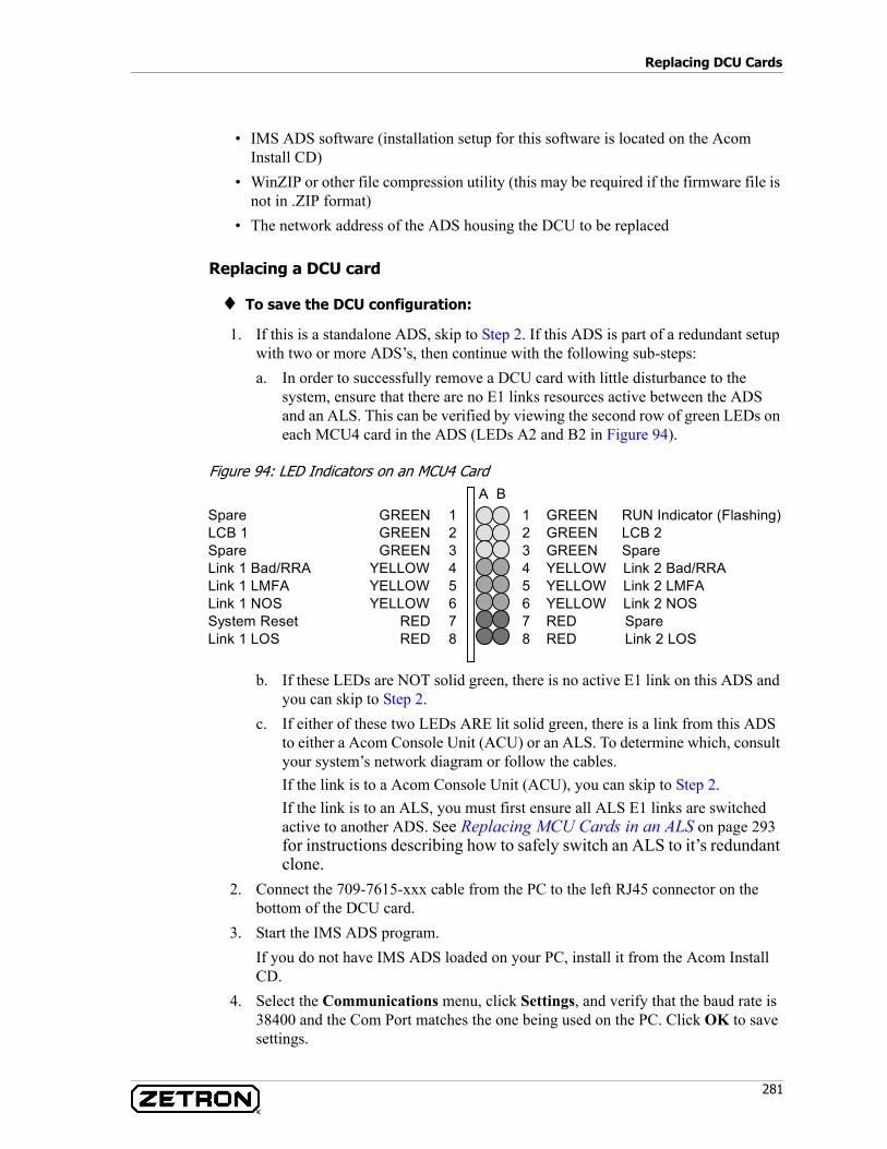
281
Replacing DCU Cards
• IMS ADS software (installation setup for this software is located on the Acom Install CD)
• WinZIP or other file compression utility (this may be required if the firmware file is not in .ZIP format)
• The network address of the ADS housing the DCU to be replaced
Replacing a DCU card
♦ To save the DCU configuration:
1. If this is a standalone ADS, skip to Step 2. If this ADS is part of a redundant setup with two or more ADS’s, then continue with the following sub-steps:a. In order to successfully remove a DCU card with little disturbance to the
system, ensure that there are no E1 links resources active between the ADS and an ALS. This can be verified by viewing the second row of green LEDs on each MCU4 card in the ADS (LEDs A2 and B2 in Figure 94).
Figure 94: LED Indicators on an MCU4 Card
b. If these LEDs are NOT solid green, there is no active E1 link on this ADS and you can skip to Step 2.
c. If either of these two LEDs ARE lit solid green, there is a link from this ADS to either a Acom Console Unit (ACU) or an ALS. To determine which, consult your system’s network diagram or follow the cables.If the link is to a Acom Console Unit (ACU), you can skip to Step 2.If the link is to an ALS, you must first ensure all ALS E1 links are switched active to another ADS. See Replacing MCU Cards in an ALS on page 293 for instructions describing how to safely switch an ALS to it’s redundant clone.
2. Connect the 709-7615-xxx cable from the PC to the left RJ45 connector on the bottom of the DCU card.
3. Start the IMS ADS program.If you do not have IMS ADS loaded on your PC, install it from the Acom Install CD.
4. Select the Communications menu, click Settings, and verify that the baud rate is 38400 and the Com Port matches the one being used on the PC. Click OK to save settings.
A B1 GREEN RUN Indicator (Flashing)2 GREEN LCB 23 GREEN Spare4 YELLOW Link 2 Bad/RRA5 YELLOW Link 2 LMFA6 YELLOW Link 2 NOS7 RED Spare8 RED Link 2 LOS
Spare GREEN 1LCB 1 GREEN 2Spare GREEN 3Link 1 Bad/RRA YELLOW 4Link 1 LMFA YELLOW 5Link 1 NOS YELLOW 6System Reset RED 7Link 1 LOS RED 8
Replacing Acom Cards and Devices
282 025-9574E
5. Select the Communications menu and click Connect. When prompted for the Network address, enter the ADS Network address and click OK.(The network address is typically on a sticker on the ADS and also can be found in the “As-Built” documents for your particular system).
6. When prompted with the password dialog, click the Default button and it should allow access to the ADS.
7. Access the File menu and select Save to Disk. When prompted for the configuration file name, use a descriptive file name. For example: ADS<network address>.bin
8. Once the file has been saved, select the Communications menu and select Disconnect.
9. Close the IMS ADS program.
♦ To record the firmware version:
1. Open a terminal program capable of serial communication.2. Open a terminal connection using the COM port connected to the DCU. The COM
port should be configured for the following settings:Bits per second = 38400 (default for an DCU)Data bits = 8Parity = NoneStop bits = 1Flow Control = None
3. Press Esc on your keyboard until you see a “Password:” prompt. It should only take three presses. If you do not get the “Password:” prompt, check the COM port and its settings.
4. When the Password prompt appears, type “8564888” and press Enter.5. A menu should appear with some selections. Press 1, then Enter.6. Once logged in, type ver and press Enter. Record the results for Release and
Library.7. To exit debug mode, press Esc, then X.
Note Make note of the Network address because it will be needed when installing the replacement card.
Note A Progress Meter window will appear when saving the file to disk. It may take up to 30 seconds to save the file. When the file save is complete, the Progress Meter window will disappear.
Note The DCU card holds the configuration for the ADS.
283
Replacing DCU Cards
♦ To remove the failed DCU:
1. Turn off power to the ADS by switching the MSU power switch off (up).2. Ground yourself with an ESD wrist strap to the ADS rack.
3. Disconnect the RJ45, BNC coax, and other connections from the front of the card.4. Use the card removal handle at the top of the card to slide the card forward.5. Remove the card and place it in an ESD bag.
♦ To install and update the new DCU:
1. Ground yourself with an ESD wrist strap to the rack.2. Remove the new card from the ESD bag.3. Align the card with the card guides at the top, then bottom of the slot.4. Slide the card into the subrack and press the card into the rear connector using both
hands on the front of the card.5. Apply power to the subrack by turning on (down) the MSU card and verify LED
activity.6. It is necessary to make sure the DCU card installed has the same version of
the DCU card removed. Verify firmware version:a. Determine the firmware version of the new card (see To record the firmware
version: on page 282) and compare with the version of the old card.b. If the DCU firmware is the same, skip to To restore ADS configuration on page
286. If the firmware versions are different, continue:7. Before you proceed with updating the firmware, make sure you have a copy of the
Ds3<version>.zip firmware file. If you do not have this file, call Zetron (see http://www.zetron.com).
8. Open the terminal program in Windows.
Warning! The DCU card is NOT hot-swappable. Power down the ADS before removing the DCU card.
Tip If the cables are not labeled, label them now so you know where to connect them on the replacement card.
Warning! The new DCU must be the same revision as the one you are replacing.
Note This procedure requires a terminal program capable of serial communication and file transfers using the 1K xmodem protocol. If this is not available, see Updating the DCU firmware (FTP alternative method): on page 285.
STOP
STOP
Replacing Acom Cards and Devices
284 025-9574E
9. Open a terminal connection using the COM port connected to the DCU. The COM port should be configured for the following settings:
Bits per second = 38400 (default for a DCU)Data bits = 8Parity = NoneStop bits = 1Flow Control = None
10. Press Esc on your keyboard until you see a “Password:” prompt. It should only take three presses. If you do not get the “Password:” prompt, check the COM port and its settings.
11. When the Password prompt appears, enter “8564888” and press Enter.12. A menu should appear with some selections. Press 1, then Enter.13. At the LR> prompt, type download. This causes the DCU to expect and wait for a
file transfer.14. Using your terminal program, send the zipped firmware file using the 1K xmodem
protocol.
15. After the file has been transferred, the DCU will flash the file to memory. This will take approximately 60 seconds. Once the firmware has been flashed, the DCU will return to the prompt.
16. Press Enter, then type RESET /Y to reset the DCU/ADS. In about 120 seconds, the DCU should come online.
17. After the DCU is online, check the firmware version to verify that the uploaded firmware is now active (see To record the firmware version: on page 282).
18. Repeat the firmware update to load the new firmware version into the other firmware image.
Warning! Choosing the incorrect file or file transfer protocol may result in a dead ACU. The only way to recover a dead ACU is to send it to Zetron for repair.
Note The DCU supports the zip file compression format. After the zip file has been transferred, the DCU will CRC check the zip file, unzip it, and update to flash.
Note The DCU holds two copies of the firmware images, and both images should be updated. The first time you send a firmware update, the DCU is using one firmware image while overwriting the other with your update. After the reset in Step 16, the DCU automatically uses the newer of the two firmware images, leaving the older firmware image ready for an update.
STOP
285
Replacing DCU Cards
♦ Updating the DCU firmware (FTP alternative method):
Use the following procedure to update the firmware on one DCU, or the first of many DCUs.
1. Place the DCU firmware file in a location on the IMS console computer where you can easily find it and FTP it to the DCU. The firmware file must be unzipped and it must be named “dcu.binary”.
2. At a Windows Command Prompt, navigate to the location of the firmware file.3. Use the following command to FTP to the DCU where [IP Address] is the IP
address of the DCU:> FTP [IP Address]
4. Press Enter for the user name (none).5. Type the password (default is 8564888).6. Select binary mode:
FTP> binary
7. Upload the firmware file:FTP> put dcu.binary
(This may take a few minutes.)8. When the FTP prompt returns, check the directory for file errors:
FTP> dir
If there are file errors in the directory, the firmware update has failed. Press the reset button on the DCU.
9. Exit FTP.FTP> quit
10. Press the reset button on the DCU.11. The resetting DCU will put on an LED “lightshow” while booting up. The status
LEDs will return to normal in a minute or two.
♦ To update the firmware for all networked DCUs:
If you haven’t already, use the previous procedure to update the firmware on the first DCU. The following procedure “copies” the updated firmware from that first DCU to all other networked DCUs.
1. At a Windows Command Prompt, Telnet to the DCU with the updated firmware:
Warning! Sending a ZIP file or using the wrong file may result in an inoperable DCU.
Warning! Failure to use binary mode will cause FTP to send a corrupt file to the DCU’s firmware. This may result in an inoperable DCU.
STOP
STOP
Replacing Acom Cards and Devices
286 025-9574E
> telnet [IP Address]
where [IP Address] is the IP address of the DCU.2. Press Enter for the user name (none).3. Type the password (default is 8564888) and press Enter. You should have an LR>
prompt.4. Use the following two commands to check the version of this DCU and all other
networked DCUs:LR> ver
LR> rver
5. The first DCU should have a newer version than the other networked DCUs.6. Update the networked DCUs:
LR> rdown /M7. As each DCU is being updated, you should see the following message where XXX
is the DCU address and YY is the slot holding the DCU.“Rack Address XXX in slot YY is burning.”
After several minutes of updating DCU firmware, the LR> prompt returns. This is an indication that the update process is complete.
8. Each DCU will reboot itself after the firmware update is complete.
♦ To restore ADS configuration
1. Launch IMS ADS on the PC. Select Communications then Connect. Enter the network address of 1 when prompted, click OK.If using a network address of 1 does not allow you access to the MCU, try using 0 or 255.
2. At password screen click default.3. Click File, Load From Disk, and select the file name that was saved earlier (see To
save the DCU configuration: on page 281).4. Click File, Update to rack.5. When prompted for the network address, use the address that provided access in
Step 1.6. When prompted for the Configuration name, use the one supplied, which should be
the name of the DCU that was replaced.7. Access the Configure menu and select Set Address. Enter the Network Address
recorded earlier in To save the DCU configuration: on page 281.8. Click File, Update to rack.9. To finalize the changes, click Tools, then Reset Rack from the IMS menu.10. When the DCU is back up and running (top right LED on DCU card is blinking
slowly) proceed to the following section.
♦ To reconnect the cables
1. Turn off power to the ADS by switching the MSU power switch off (up).
287
Replacing Acom Console Units
2. Re-connect the cables to the front of the card.3. Turn power on the ADS.4. Wait 120 seconds for the ADS to come on line.5. Make ALSs connected to this DCU/ADS active by performing an ALS changeover
described in Replacing MCU Cards in an ALS on page 293.6. Test some line resources to verify that the system resources are functional on this
DCU/ADS.
Replacing Acom Console Units
The Acom Console Unit provides the console data and voice interfaces for the position. The unit holds up to four expansion modules.
♦ To remove an Acom Console Unit:
1. Back up the unit's configuration to disk using IMS. (See Acom Software Installation and Configuration, P/N 025-9529.) Note the Acom Console Unit’s network address displayed in the title bar of IMS ACU.
2. Make a note of the unit's firmware version; the new Acom Console Unit must be the same revision. Using IMS ACU, access the ACU and hover the mouse over the Dual E1 card and the firmware version will appear in the status bar on the bottom of the IMS ACU program.
3. Turn off power to the Acom Console Unit using the switch on the rear of the unit.4. Disconnect AC power from the rear of the unit.5. Disconnect all serial connections from the data ports, noting their connection and
marking if needed.6. Disconnect all voice connections from the OAM or 4-Wire E&M Modules.7. Disconnect the Digital Input and Digital Output connectors if used.8. Remove the ground lead from the Acom Console Unit.9. Remove the E1 cables from the Dual E1 card.10. With all leads disconnected, unscrew the unit from the underside of the desk.
Replacing Acom Cards and Devices
288 025-9574E
♦ To install a Acom Console Unit/ACU:
1. If the ACU is not being mounted under the desk, skip to Step 5.2. Install any required modules in the ACU. See Replacing Acom Console Unit
Daughter Cards on page 290.3. Install the under desk mounting option.4. Screw the ACU to the under side of the work surface using self-tapping screws.5. Make all serial connections to the data ports. The ACS serial connection often uses
ACU COM1.6. Make all voice connections to the OAM or 4-Wire E&M Modules. Refer to the
position layout drawing for your system for specific details on position connections.
• Jackbox or TRHI• Speakers• PC Tones
7. Connect any digital I/Os. This may include foot switches, TRHI, or active conversation lamps.
8. Connect the ground lead to the ground post near the power connection.9. Connect the AC power cable and turn on the ACU using the power switch on the
rear of the unit.10. Access the ACU using IMS ACU. When prompted for the network address, try
using 2, 0, or 255.11. Hover the mouse over the Dual E1 card and note the firmware version. If the
firmware version is NOT the same as the ACU being replaced, continue to the next step. Otherwise, skip to Step 20.
12. Move the ACS cable currently plugged in the ACU Data Port COM1 to COM4.13. Open a terminal connection using the COM port connected to the ACU. The COM
port should be configured for the following settings:Bits per second = 38400 (default for a ACU)Data bits = 8Parity = NoneStop bits = 1Flow Control = None
Note If a firmware update is needed, then a zipped ACU firmware update file is required for this procedure. This file is typically supplied via email from Zetron technical support or located on the Acom Install CD. The supplied file may be titled ACU_101.zip or similar.
Note This procedure requires a terminal program capable of serial communication and file transfers using the 1K xmodem protocol.

289
Replacing Acom Console Units
14. Press Esc on your keyboard until you see a “Password:” prompt. It should only take three presses. If you do not get the “Password:” prompt, check the COM port and its settings.
15. When the Password prompt appears, type 8564888 and press Enter.16. Once logged in, type ver and press Enter and record the current version.17. Using your terminal program, send the zipped firmware file using the 1K xmodem
protocol.
18. After the firmware has been uploaded, the ACU will reset itself. Once it appears that the ACU is operating again, press Esc three times to get another Password prompt. Enter 8564888 and type ver to verify that the ACU now has the current version.If the version is correct, type Exit to end the debug session.
19. Move the ACS cable currently plugged in the ACU Data Port COM4 to COM1.20. Using IMS ACU, access the File menu and select Load from disk.
Locate the save file and load it.21. From the File menu, select Update to NVRAM.
When prompted for the Network address, try 2, 0, or 255.When prompted for the Configuration name, use the one supplied.
22. Access the Configure menu and select Network Address.23. Enter the appropriate Network Address recorded earlier.24. Access the File menu and select Update to NVRAM.25. Power down the ACU and connect the E1 cables to the Dual E1 card.26. Power on the ACU and verify that it is online and ACS is operational.
Warning! Choosing the incorrect file or file transfer protocol may result in a dead ACU. The only way to recover a dead ACU is to send it to Zetron for repair.
Note The ACU supports the zip file compression format. After the zip file has been transferred, the ACU will CRC check the zip file, unzip it, and update to flash. It is recommended that you keep the firmware update in the zip file and do not unzip it before transferring to the ACU. This will minimize the transfer time and protect the bin file with the CRC checking provided by the zip format.
STOP

Replacing Acom Cards and Devices
290 025-9574E
Replacing Acom Console Unit Daughter Cards
The Acom Console Unit daughter cards are available in several varieties:
♦ Removal:
1. Ground yourself to the Acom Console Unit using an ESD wrist strap.2. Remove the Acom Console Unit (see Replacing Acom Console Units on page
287).3. Remove the screws that secure the top cover on the Acom Console Unit using a
medium Phillips screwdriver.4. Remove the Allen screws that secure the cover plate on the rear of the module.5. Remove the two Phillips screws that secure the card inside the Acom Console
Unit.6. Gently pull the card toward the rear of the Acom Console Unit to unseat the
connector.7. Lift the module out over the guide posts and place it in an ESD bag.8. Secure the top cover of the Acom Console Unit using the existing screws.
♦ Installation:
1. Ground yourself to the Acom Console Unit using an ESD wrist strap.2. Follow the instructions for removing the Acom Console Unit.3. Remove the screws that secure the top cover on the Acom Console Unit using a
medium Phillips screwdriver.4. If there is a cover plate at the intended location for the module, remove the Allen
screws that secure the cover plate and set the plate aside.5. Set the module into the Acom Console Unit slot so it fits over the guide posts and
gently slide it into the connector.6. Secure the card inside the Acom Console Unit with two provided Phillips screws.
Dual E1 Module Provides multiple E1 connections for installing the position in an E1 loop. The Dual E1 must be installed in slot 0 (farthest away from data ports).
Dual 4-Wire E&M Module
Provides two 4-wire E&M interfaces for IRR, desk mic, speakers or other purposes.
Operator's Audio Module (OAM)
Provides voice and data ports for speakers, handsets, mics, and more.
DCOAM Provides voice, logging, foot switch, PC Tones, and handset ports.
Warning! Please exercise electro-static discharge (ESD) precautions when handling all cards.
STOP
291
Replacing EIE, TIE, or EMU Cards
7. Attach the new cover plate using the existing Allen screws.8. Secure the top cover of the Acom Console Unit using the existing screws.9. Install the Acom Console Unit (see Replacing Acom Console Units on page 287).
Replacing EIE, TIE, or EMU Cards
The EIE card provides six independent ring in/loop out channels that interface to CO provided POTS circuits. This card is hot-swappable.
The TIE card provides six independent ring out/loop in channels that interface to local phones. This card is hot-swappable.
The EMU card provides six independent 4-wire E&M channels that interface to radios or other 4-wire circuits. This card is hot-swappable.
♦ To remove the old card:
1. If this ALS is part of a Main-Standby setup and it is currently in control, force control over to the other ALS:a. Launch IMS Terminal, and login.b. Double click the ALS. From the Tools menu, select Change Over, select the
Manual option and select the ALS NOT in control.c. Verify that the icon in IMS turns blue for the other ALS.d. Select the Automatic option and exit the Change Over menu.
2. Power down the subrack by setting the toggle switch on the MSU card to the UP position.
3. Use a grounding wrist strap to prevent ESD damage to the equipment.4. Carefully disconnect the EURO96 connectors from the front of the card by
squeezing at the top and bottom of the connector while pulling straight out.5. Flip top lever on card upward to dislodge it from the backplane connector. Slide
card out slowly and carefully.6. Place card in ESD bag.
Warning! Please exercise electro-static discharge (ESD) precautions when handling all cards.
STOP
Note Although these cards are hot swappable, it is preferable to turn off the power when swapping out any cards in the system.
Subrack programming is not required when replacing these cards.
Replacing Acom Cards and Devices
292 025-9574E
♦ To install the replacement card:
1. Ground yourself with an ESD wrist strap connected to the rack.2. Remove the new card from the ESD bag.3. For an EIE card with part numbers 950-0522 or 950-0637, check jumpers JP6, JP8,
and JP9. These jumpers need to be set to “Dual” or “Single” (as printed on the board itself), depending on whether the subrack has dual or single backplanes. EIE cards with part number 950-0491 do not have jumpers for this purpose and are compatible with dual backplanes only.
4. Align the card with the card guides at the top, then bottom of the slot.5. Slowly and carefully slide the card into the subrack.6. Press the card into the rear connector using two hands on the front of the card.7. Connect the EURO96 connectors to the front of the card.8. Apply power to the subrack.9. Verify in IMS Terminal that the new card appears and the slot box for it is green.10. If this ALS is part of a Main-Standby setup, force control back to this ALS:
a. From the Tools menu in IMS Terminal, select Change Over.b. Select the Manual option and select this ALS.c. Verify the ALS icon in IMS turns light blue to show that this ALS is in control.d. Once this ALS has taken control, select the Automatic option and exit the
Change Over menu.11. Test the new card. Verify that the run LED flashes.
Replacing Jackbox 950-0474
The jackbox is the headset or handset interface for the Acom Console Unit.
♦ Removal:
1. Remove the jackbox audio connection from OAM RJ45 port on the rear of the Acom Console Unit.
2. Using a flat head screwdriver, remove the cover plate of the jackbox.3. Remove the jackbox by unscrewing it from its mounted location.
♦ Installation:
1. Using a flat head screwdriver, remove the cover plate of the jackbox.
Note For a 5v-12v version of the EMU card (P/N 950-0841), jumpers J1 through J12 must always be in the 2-3 position.
293
Replacing MCU Cards in an ALS
2. Secure the jackbox to the underside of the work surface using self-tapping screws. Mount the jackbox far enough away from the front edge of the work surface to prevent the handset connector from protruding.
3. Install the jackbox cover plate using the existing flat head screws.4. Route the audio connection to the OAM module of the Acom Console Unit and
connect it to one of the HS ports (HS1/HS2).
Replacing MCU Cards in an ALS
This procedure is only for an MCU3 or MCU4 in an ALS. For an MCU4 in an ADS, see Replacing MCU Cards in an ADS on page 297.
If an MCU card is installed in slot 0 of an ALS, it is considered the primary MCU; it holds the configuration for the subrack and controls all rack messaging.
Required Equipment
• Straight-through RS232 serial cable(Zetron cable part number 709-7345)
• Laptop/PC with Windows or better and a serial port.• IMS Program. (Typically installed from the Acom install disk)• Winzip or other unzipping utility if installing using an emailed zip file.
♦ To backup the MCU configuration:
1. Connect the laptop’s serial com port to port 1 of the MCU card. (Port 1 of the MCU card is the top 9-pin serial connector on the front of the MCU card, labeled X17 on the PCB.)
2. Launch IMS ALS on the laptop.3. From the main menu, select Communications then Connect.
Warning! The Primary MCU is NOT hot-swappable. Only secondary MCU cards are hot-swappable.
Caution! The new MCU must be the same revision as the one you removed.
Note It is preferred that the power be turned off when swapping out any cards in the system.
STOP
!
Replacing Acom Cards and Devices
294 025-9574E
4. When prompted, enter the Network Address of the subrack, and click OK. (The network address is typically on a sticker on the subrack and can also be found in the as-built documents for your system.)
5. At the password screen click the default button.6. If this ALS is part of a Main-Standby setup, force control to the other ALS:
a. From the Tools menu in IMS Terminal, select Change Over.b. Select the Manual option and select the other ALS.c. Verify the ALS icon in IMS turns light blue to show that the other ALS is in
control.d. Once the other ALS has taken control, select the Automatic option and exit
the Change Over menu.7. Once connected choose File then Save to Disk. Save the file with a descriptive
name, for example:ADS<network address>.cfg
8. Choose Configure then Subrack Address write down the subrack address. Also note if this is the Main or Standby ALS.
9. Select the Communications menu then Disconnect to disconnect from the ALS.
♦ To record the current firmware version:
1. Open a terminal program capable of serial communication.2. Open a terminal connection using the COM port connected to the MCU. The COM
port should be configured for the following settings:Bits per second = 38400 (default for an MCU)Data bits = 8Parity = NoneStop bits = 1Flow Control = None
3. Press Esc on your keyboard until you see a “Password:” prompt. It should only take three presses. If you do not get the “Password:” prompt, check the COM port and its settings.
4. When the Password prompt appears, type the password (default 8564888) and press Enter.
5. Once logged in, type ver and press Enter.6. Record the results.
Note A Progress Meter window will appear when saving the file to disk. It can take several minutes to completely save the file. When the file save is complete, the Progress Meter window will disappear.
295
Replacing MCU Cards in an ALS
♦ To remove the old MCU card:
1. Power down the subrack by setting the toggle switch on the MSU card to the up position.
2. Use a grounding wrist strap to prevent ESD damage to the equipment.3. If the cables are not labeled, label them now so you know where to plug them in on
the new card.4. Disconnect all cables from front of MCU card.
For SMB connections, grab them at the elbow with the thumb and index finger, and pull gently straight out.If a net clock connection exists, make a note of the port it is connected to before removing it.
5. Flip the top lever on MCU card to dislodge it from the backplane connector. Slide the card out slowly and carefully.
6. Place card in ESD bag.
♦ To install the new MCU card:
1. Ground yourself with an ESD wrist strap connected to the rack.2. Remove the new card from the ESD bag.3. Align the card with the card guides at the top, then bottom of the slot.4. Slowly and carefully slide the card into the subrack.5. Press the card into the rear connector using two hands on the front of the card.
Do NOT connect the SMB cables to the new MCU at this time.6. Apply power to the subrack and verify that the top right green LED is blinking
slowly approximately once per second. This shows that the MCU up and running.
♦ To verify or upgrade the firmware of the card:
Requirements:• A zipped MCU3 firmware update file. This is typically supplied via email
from zetron technical support or located on the Acom Install CD. The supplied file may be titled “ADS_100.zip” or similar.
1. Open a terminal program capable of serial communication.2. Open a terminal connection using the COM port connected to the MCU. The COM
port should be configured for the following settings:Bits per second = 38400 (default for an MCU)Data bits = 8Parity = NoneStop bits = 1
Note The sub rack will not function while updating the firmware on a Primary MCU card.
Replacing Acom Cards and Devices
296 025-9574E
Flow Control = None3. Press Esc on your keyboard until you see a “Password:” prompt. It should only
take three presses. If you do not get the “Password:” prompt, check the COM port and its settings.
4. When the Password prompt appears, type the password (default 8564888) and press Enter.
5. Once logged in, type ver and press Enter.
6. At the prompt, type Download and press Enter. This command will cause the MCU to prompt for a Xmodem transfer by sending a “C” character repeatedly.
7. Using your terminal program, send the zipped firmware file using the 1K xmodem protocol.
8. After the MCU has reset itself and appears to be operating again, press Esc three times to get another “Password” prompt.
9. Type ver and note the results.
♦ To restore the ALS configuration:(only if replacing MCU in slot 0)
1. On the laptop, launch IMS ALS.2. Select “Communications” then “Connect”.3. Enter the network address of 1 when prompted, and click OK.
If using a network address of 1 does not allow you access to the MCU, try using 0 or 255.
4. At the password screen, click default.5. Click File, then Load From Disk and choose the file name that was saved in To
backup the MCU configuration: on page 293.6. Select File, then Update To Rack to transfer the new file to the ALS.
Note If the firmware version is the same as recorded in To backup the MCU configuration: on page 293, then skip the remaining steps in this procedure and proceed to the next procedure.
Warning! Choosing the incorrect file or file transfer protocol may result in a dead MCU card. The only way to recover a dead MCU card is to send it to Zetron for repair.
Note The MCU supports the zip file compression format. After the zip file has been transferred, the MCU will CRC check the zip file, unzip it, and update to flash. It is recommended that you keep the firmware update in the zip file and do not unzip it before transferring to the MCU. This will minimize the transfer time and protect the bin file with the CRC checking provided by the zip format.
STOP
297
Replacing MCU Cards in an ADS
7. When prompted for the network address, use the one that worked correctly in Step 3.
8. When prompted for the configuration name, use the one supplied, which should be the name of the MCU that was replaced.
9. Click Tools, then Reset Rack from the IMS menu to finalize the changes.10. Click File, Update To Rack.11. When the rack is back up and running (top right LED on MCU card is blinking
slowly), reconnect and verify the network and subrack addresses.12. Select Configure, then Subrack Address.
Set the subrack address to the value recorded in To backup the MCU configuration: on page 293, then click Save.
13. Click Configure, then Network Address.Set the network address to the same value recorded in To backup the MCU configuration: on page 293, then click Save.
14. Power down the rack and reconnect the SMB cables to the MCU.15. Power up the rack.
Within a minute or two, the rack should be operating normally. Only the top right green LED on the MCU should be flashing and on if everything is normal.
♦ To switch back to this rack and test:
1. Select Tools, then Change over.2. Set “Mode” to manual.3. Under “Select Active Device” click the button for the offline rack. This should
force a cut over back to this ALS.4. Set “Mode” back to Automatic.5. Go to the Acom Console PC. Verify in IMS ALS that this subrack is now blue
(online-OK) and the other rack is green (offline-OK)
Replacing MCU Cards in an ADS
This procedure is only for an MCU4 in an ADS. For an MCU3 or MCU4 in an ALS, see Replacing MCU Cards in an ALS on page 293.
Required Equipment
• Zetron straight through cable part number 709-7345• PC/Laptop equipped with Windows or better and an RS232 Serial Com Port• IMS ADS software
(installation for this software is located on the Acom Install CD)
Replacing Acom Cards and Devices
298 025-9574E
• WinZIP or other file compression utility(this may be required if the firmware file is not in .ZIP format)
♦ To verify MCU4/ADS is not active:
1. If this is a standalone ADS, skip to the next procedure To record the firmware version: on page 298.If this ADS is part of a redundant setup with two or more ADS’s, then continue.
2. Make sure no E1 links are active on the ADS. This can be verified by viewing the second row of green LEDs (right below the top right flashing green LED) on each MCU4 card in the ADS. For a diagram of MCU LEDs, see Figure 60 MCU4 Status Indicators (When Used in an ADS) on page 187.If any of these LEDs are lit solid, there is either a link to a Acom Console Unit/ACU or an active link to an ALS. Consult the system Network Diagram or follow the cables and make sure it’s NOT an active E1 link to an ALS.If there are no active E1 links to an ALS, skip to the next procedure, To record the firmware version: on page 298. If there are active links to an ALS, make sure that all ALS E1 links are switched active to the other ADS:a. At the IMS console, launch IMS Terminal, and login.b. Double click the ALS. From the Tools menu, select Change Over, select the
Manual option and select the ALS NOT in control.c. Verify that the icon in IMS turns blue for the other ALS.d. Select the Automatic option and exit the Change Over menu.
♦ To record the firmware version:
1. Open a terminal program capable of serial communication.2. Open a terminal connection using the COM port connected to the MCU. The COM
port should be configured for the following settings:Bits per second = 38400 (default for a MCU)Data bits = 8Parity = NoneStop bits = 1Flow Control = None
3. Press Esc on your keyboard until you see a “Password:” prompt. It should only take three presses. If you do not get the “Password:” prompt, check the COM port and its settings.
4. When the Password prompt appears, enter 8564888 and press Enter.5. A menu should appear with some selections. Enter 1 and press Enter.6. Once logged in, type ver and press Enter.7. Record the results for Release and Library.
299
Replacing MCU Cards in an ADS
8. Press the Esc key then press X to exit debug.
9. Ground yourself with an ESD wrist strap to the ADS rack.
10. Disconnect the SMB connections from the front of the MCU4 card by grasping the gold connectors and pulling on them. DO NOT pull on the cable itself or you may damage the cable.
11. Disconnect the DB9 serial cable.12. Use the card removal handle at the top of the card to slide the card forward.13. Remove the card and place in an ESD bag.
♦ To install the MCU4:
1. Ground yourself with an ESD wrist strap to the rack.2. Remove the new card from the ESD bag.3. Align the card with the card guides at the top, then bottom of the slot.4. Slide the card into the subrack and press the card into the rear connector using both
hands on the front of the card.5. Apply power to the subrack by turning on (down) the MSU card.6. Verify LED activity.
♦ To verify and update the firmware version:
1. It is necessary to make sure the MCU4 card installed has the same firmware version of the MCU4 card removed.
2. Check the firmware version of the new card and compare it with the firmware version you recorded for the old card (see To record the firmware version: on page 298).
3. If the MCU4 firmware is the same, skip to To reconnect the cables: on page 300.4. Before you proceed, make sure you have a copy of the MCU4<version>.zip
firmware file. If you do not have this file, call Zetron.5. Open a terminal program capable of serial communication.6. Open a terminal connection using the COM port connected to the MCU. The COM
port should be configured for the following settings:
Warning! The new MCU4 must be the same revision as the one you are replacing.
Note Although the MCU4 card is hot-swappable, it is preferred that the power be turned off when swapping out any cards in the system.
Warning! If the cables are not labeled, label them so you know where to connect them on the replacement card.
STOP
STOP
Replacing Acom Cards and Devices
300 025-9574E
Bits per second = 38400 (default for a MCU)Data bits = 8Parity = NoneStop bits = 1Flow Control = None
7. Press Esc on your keyboard until you see a “Password:” prompt. It should only take three presses. If you do not get the “Password:” prompt, check the COM port and its settings.
8. When the Password prompt appears, enter “8564888” and press Enter.9. A menu should appear with some selections. Enter 1 then press Enter.10. At the MCUX> prompt, type download. The download process will begin.11. Using your terminal program, send the zipped firmware file using the 1K xmodem
protocol.
12. After the file has been transferred, the MCU4 will flash the file to memory then reset. This will take about 60 seconds.
13. After the MCU4 is online, check the firmware version to verify that the uploaded firmware is now active (see To verify and update the firmware version: on page 299).
♦ To reconnect the cables:
1. Turn off power to the ADS by switching the MSU power switch off (up).2. Re-connect the cables to the front of the card.3. Restore power to the ADS by switching the MSU power switch on (down).4. Wait 120 seconds for the ADS to come on line.5. Make ALSs connected to this MCU4/ADS active by performing a changeover
described in Replacing MCU Cards in an ALS on page 293.6. Test some line resources to verify that the system resources are functional on this
MCU4/ADS.
Warning! Choosing the incorrect file or file transfer protocol may result in a dead MCU4 card. The only way to recover a dead MCU4 card is to send it to Zetron for repair.
Note The MCU4 supports the zip file compression format. After the zip file has been transferred, the MCU4 will CRC check the zip file, unzip it, and update to flash.
STOP
301
Replacing MSU Cards
Replacing MSU Cards
♦ To remove the old MSU card:
1. If this ALS is part of a Main-Standby setup and it is currently in control, force control over to the other ALS:a. At the IMS console, launch IMS Terminal, and login.b. Double click the ALS. From the Tools menu, select Change Over, select the
Manual option and select the ALS NOT in control.c. Verify that the icon in IMS turns blue for the other ALS.d. Select the Automatic option and exit the Change Over menu.
2. Power down the subrack by setting the toggle switch on the MSU card to the up position.
3. Remove power from the rack at the fuse or breaker panel.4. Use a grounding wrist strap to prevent ESD damage to the equipment.5. Carefully disconnect the EURO96 connector from the front of the card by
squeezing at the top and bottom of the connector while pulling straight out.6. Remove the weidmuller 48volt power connection from the front of the MSU by
pulling straight out.7. Flip top lever on card upward to dislodge it from the backplane connector. Slide
card out slowly and carefully.
♦ Install replacement card:
1. Verify that power has been removed from the subrack at the fuse or breaker panel.2. Ground yourself with an ESD wrist strap connected to the rack.3. Remove the new card from the ESD bag.4. Review the jumpers on the old card and verify all jumpers are set the same on the
new card.5. Place card old card in ESD bag.6. Verify MSU power switch is in the UP position.7. Align the card with the card guides at the top, then bottom of the slot.8. Slowly and carefully slide the card into the subrack.9. Press the card into the rear connector using two hands on the front of the card.
Note Please exercise electro-static discharge (ESD) precautions when handling all cards.
Warning! The MSU card is NOT hot-swappable.STOP
Replacing Acom Cards and Devices
302 025-9574E
10. Connect the EURO96 connector and weidmuller power connector to the front of the card.
11. Apply power to the rack using the fuse panel or circuit breaker.12. Push the power switch DOWN on the MSU.13. Verify in IMS Terminal that the ALS with the replaced MSU card appears and has
no Urgent Alarms.14. If this ALS is part of a Main-Standby setup, force control back to this ALS:
a. From the Tools menu in IMS Terminal, select Change Over.b. Select the Manual option and select this ALS.c. Verify the ALS icon in IMS turns light blue to show that this ALS is in control.d. Once this ALS has taken control, select the Automatic option and exit the
Change Over menu.15. Test the new card. Verify that the run LED flashes.
Replacing RVA Cards
The RVA card provides Acom with the capability of using recorded voice announcements. The RVA card is hot-swappable. Recorded announcements are stored in non-volatile memory, so recordings are retained even if the RVA card loses power. This also means you can move the RVA card from one slot to another without losing the recordings.
♦ To remove an RVA card:
1. If the ALS that contains the RVA card is part of a Main-Standby setup, force control over to the other ALS:a. At the IMS console, launch IMS Terminal, and login.b. Double click the ALS. From the Tools menu, click Change Over, the Manual
option, and then select the ALS NOT in control.c. Verify that the icon in IMS turns blue for the other ALS.d. Select the Automatic option and exit the Change Over menu.
2. In IMS, make a note of the card’s firmware version; the new card must be the same revision. Ground yourself with an ESD wrist strap attached to the rack.
3. If there is an audio device connected to the headset jack, remove the device.4. Use the card removal handle at the top of the card to slide the card forward.5. Remove the card and place it in an ESD bag.
Warning! Please exercise electro-static discharge (ESD) precautions when handling all cards.
STOP
303
Replacing SMU Cards
♦ To install an RVA card:
1. Ground yourself with an ESD wrist strap attached to the rack.2. Remove the new card from the ESD bag.3. Align the card with the card guides at the top, then bottom of the slot.4. Slide the card into the subrack.5. Press the card into the rear connector using both hands on the front of the card.6. If applicable, reconnect the audio device to the headset jack.7. Verify that the card can be seen in IMS and that the run LED flashes (see Recorded
Voice Announcement (RVA) Card on page 235).8. Upgrade the unit's firmware if necessary (contact Zetron Technical Support).9. If necessary, use IMS to download or record your voice announcements to RVA
card. (See Acom Software Installation and Configuration, P/N 025-9529.)
Replacing SMU Cards
The SMU card provides all signalling for the subrack (VOX, DTMF, TRC, AGC, …). It may alternatively be used for VoIP radio interfaces such as OpenSky. This card is hot-swappable.
Required Equipment
• Zetron SMU cable, part number 709-7592-xxx (xxx=cable length)• PC with Windows, serial com port, and terminal software capable of serial comm
♦ To record the current Firmware version:
1. If the ALS that contains the SMU card is part of a Main-Standby setup, force control over to the other ALS:a. At the IMS console, launch IMS Terminal, and login.b. Double click the ALS. From the Tools menu, click Change Over, the Manual
option, and then select the ALS NOT in control.
Caution! Please exercise electro-static discharge (ESD) precautions when handling all cards.
!
Note Although these cards are hot swappable, it is preferable that the power be turned off when swapping out any cards.
No subrack programming is required when replacing these cards.
Replacing Acom Cards and Devices
304 025-9574E
c. Verify that the icon in IMS turns blue for the other ALS.d. Select the Automatic option and exit the Change Over menu.
2. Connect the SMU cable between the PC and the front connector on the SMU. The connector on the SMU is keyed and can only fit properly one way.
3. Open a terminal program capable of serial communication.4. Open a terminal connection using the COM port connected to the SMU. The COM
port should be configured for the following settings:Bits per second = 38400 (default for a SMU)Data bits = 8Parity = NoneStop bits = 1Flow Control = None
5. Press Esc on your keyboard until you see a “Password:” prompt. It should only take three presses. If you do not get the “Password:” prompt, check the COM port and its settings.
6. When the Password prompt appears, enter 8564888 and press Enter.7. Once logged in type ver and press Enter, record the results.
♦ To remove the old card:
1. If the ALS that contains the SMU card is part of a Main-Standby setup, force control over to the other ALS:a. At the IMS console, launch IMS Terminal, and login.b. Double click the ALS. From the Tools menu, select Change Over, select the
Manual option and select the ALS NOT in control.c. Verify that the icon in IMS turns blue for the other ALS.d. Select the Automatic option and exit the Change Over menu.
2. Use a grounding wrist strap to prevent ESD damage to the equipment.3. Flip top lever on card upward to dislodge it from the backplane connector. Slide
card out slowly and carefully.4. Place card in ESD bag.
♦ To install the replacement card:
1. Ground yourself with an ESD wrist strap connected to the rack.2. Remove the new card from the ESD bag.3. Align the card with the card guides at the top, then bottom of the slot.4. Slowly and carefully slide the card into the subrack.5. Press the card into the rear connector using two hands on the front of the card.6. Verify in IMS Terminal that the ALS is reporting no Urgent Alarms.
305
Replacing Telephone Radio Handset Interfaces (TRHI)
♦ To verify or upgrade the firmware of the SMU:
Requirements:• SMU update file. This is typically supplied via email from Zetron technical
support or located on the Acom Install CD. The supplied file may be titled “smu_141.raw” or similar.
1. Open a terminal session as described in To record the current Firmware version: on page 303.
2. Press Esc until you see a “Password:” prompt, it should only take three presses. If you do not get the “Password:” prompt, check the COM port and its settings.
3. When the Password prompt appears, enter 8564888 and press Enter.4. Once logged in type ver and press Enter, record the results.
5. Type Download and press Enter. This command will cause the SMU to prompt for a Xmodem transfer by sending a “C” character repeatedly.
6. Using your terminal program, send the zipped firmware file using the 1K xmodem protocol.
7. Press Esc three times to get another Password prompt.8. Type 8564888 and press Enter.9. Type the ver command again and note the results.
Replacing Telephone Radio Handset Interfaces (TRHI)
The Telephone Radio Handset Interface (TRHI) provides a common point between a phone and radio system to allow for a single headset to service both systems. It functions as a jackbox and handset interface, but also as an audio amplifier and switching device.
Warning! The sub rack will not function properly while updating the SMU firmware.
Note If firmware version in the new card is the same as the firmware version recorded earlier in the old card, then the install has been completed.
Warning! Choosing the incorrect file or file transfer protocol may result in a dead SMU card. The only way to recover a dead SMU card is to send it to Zetron for repair.
STOP
STOP
Replacing Acom Cards and Devices
306 025-9574E
♦ Removal:
1. Disconnect the ground wire from the rear of the TRHI.2. Disconnect power from the TRHI.3. Disconnect the DB9 and Weidmuller connections from the rear of the TRHI.4. Remove the side screws that hold the TRHI to the top cover and remove the unit
from under the desk. If you are not replacing this unit, remove the top cover as well.
♦ Installation:
1. Remove the top cover and set the jumpers as required. Refer to the previously installed unit's settings or TRHI manual 025-9553.
2. Secure the TRHI top cover to the bottom of the writing surface using the supplied screws. Mount the TRHI far enough away from the front edge of the work surface to prevent the handset connector from protruding.
3. Attach the body of the interface to the top cover.4. Connect the case ground, located on the rear panel, to the central earth ground.5. Install cable 709-7629 or 709-7684 between the DB9 connector of the TRHI and
one of the HS ports of the OAM (HS1/HS2). (Cable 709-7629 draws power from the Acom Console Unit and cable 709-7684 draws power from an AC/DC transformer.)
6. Connect the lead labelled “PTT” to the Acom Console Unit’s digital output pin 2.7. Connect the lead labelled “HSE” to the Acom Console Unit’s digital input pin 6.8. Connect the 12V power source to the TRHI.9. Perform level adjustments described in the TRHI manual (P/N 025-9553).
Replacing UIO Cards
♦ To remove the old card:
1. If the ALS that contains the UIO card is part of a Main-Standby setup, force control over to the other ALS:a. At the IMS console, launch IMS Terminal, and login.
Caution! Please exercise electro-static discharge (ESD) precautions when handling all cards.
Note Although these cards are hot swappable, it is preferable that the power be turned off when swapping out any cards in the system.
!

307
Replacing UIO Cards
b. Double click the ALS. From the Tools menu, select Change Over, select the Manual option and select the ALS NOT in control.
c. Verify that the icon in IMS turns blue for the other ALS.d. Select the Automatic option and exit the Change Over menu.
2. Power down the subrack by setting the toggle switch on the MSU card to the up position.
3. Use a grounding wrist strap to prevent ESD damage to the equipment.4. Carefully disconnect the EURO96 connector from the front of the card by
squeezing at the top and bottom of the connector while pulling straight out.5. Flip top lever on card upward to dislodge it from the backplane connector. Slide
card out slowly and carefully.
♦ Install replacement card:
1. Ground yourself with an ESD wrist strap connected to the rack.2. Remove the new card from the ESD bag.3. Review the jumpers on the old card and verify all jumpers are set the same on the
new card.4. Place card old card in ESD bag.5. Align the card with the card guides at the top, then bottom of the slot.6. Slowly and carefully slide the card into the subrack.7. Press the card into the rear connector using two hands on the front of the card.8. Connect the EURO96 connector to the front of the card.9. Apply power to the subrack.10. Verify in IMS Terminal that the new card appears and that the slot box for it is
green.11. If this ALS is part of a Main-Standby setup, force control back to this ALS:
a. At the IMS console, launch IMS Terminal, and login.b. Double click the ALS. From the Tools menu, select Change Over, select the
Manual option and select the ALS NOT in control.c. Verify that the icon in IMS turns blue for this ALS.d. Select the Automatic option and exit the Change Over menu.
12. Test some of the UIO input to make sure they are functional.

Replacing Acom Cards and Devices
308 025-9574E
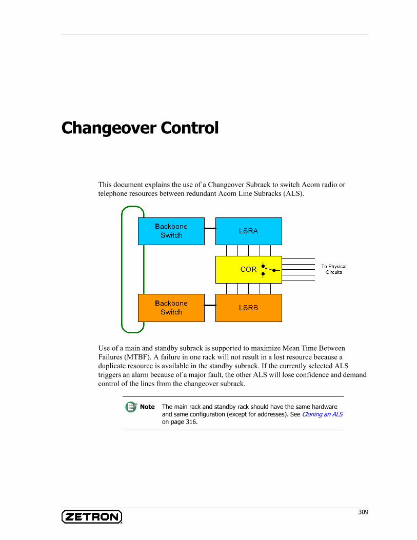
309
Changeover Control
This document explains the use of a Changeover Subrack to switch Acom radio or telephone resources between redundant Acom Line Subracks (ALS).
Use of a main and standby subrack is supported to maximize Mean Time Between Failures (MTBF). A failure in one rack will not result in a lost resource because a duplicate resource is available in the standby subrack. If the currently selected ALS triggers an alarm because of a major fault, the other ALS will lose confidence and demand control of the lines from the changeover subrack.
Note The main rack and standby rack should have the same hardware and same configuration (except for addresses). See Cloning an ALS on page 316.
Changeover Control
310 025-9574E
Changeover Hardware
The Acom changeover control system is primarily composed of a main, standby, and changeover subrack. Each rack is equipped with cards to support the hot standby application. The E1 links from the subrack to the ADS (Acom DS3 Switch) are not switched, a combination of signaling lines between the racks determine which E1 link is considered active to be presented to the system backbone.
The Acom Line Subrack (ALS)
An Acom Line Subrack consists of a Main Control Unit (MCU), a Main Supply Unit (MSU), a subrack assembly, and line cards. Each redundant pair of ALSs in the changeover system should be equipped and configured identically with all of the same resources so switchover is seamless to the user.
An ALS will demand control when it loses confidence in the opposite subrack. By monitoring the Watchdog (AI13) and Standby Fault (AI21) alarm outputs of the opposite subrack, the MSU card can demand a switchover to take control by asserting the System Select (AO11) output. By momentarily grounding this output, the MSU will signal the Changeover Control Card (CCC) in the Changeover subrack that it wishes control of the radio and phone lines. The CCC will command all COV-V, COV-R, and COV-T relay cards to switch lines over to give the subrack control and will assert the System A Selected or System B Selected outputs to tell the subracks which ALS now has control. This CCC output is connected to the MSU “System Selected” input (AI11) and a parallel connection is made to the ADS input.
MSU
The Main Supply Unit (MSU) serves many functions in an Acom system, system tone generation, DC-DC conversion, and alarm inputs and outputs. The MSU has six input and six output alarms. MSU input alarms are pulled high to –48 volts by the MSU card’s internal jumpers JP1-JP6. A ground on any of these inputs will cause the input to become active. The output alarms of the MSU are opto-isolated common collector outputs that pull to ground (+VV) when active.
System Selected and Select System (AO11/AI11)
The SYSSEL output (AO11) is grounded by the MSU card to signal the CCC card that it wishes to take control. AI11 is then grounded by the CCC card to signal the MSU that it has control. The subrack will take control when it sees its Standby Fault input go active or its Watchdog Fault input go inactive. The subrack may additionally take control if the local alarms clear and the opposite subrack still has either a Standby Fault or Watchdog Fault.
311
Changeover Hardware
Standby Fault (AO21/AI21)
This is the primary health alarm of the subrack. It is used to signal the other subrack when it has an urgent alarm. The output is programmable; it is useful to configure this alarm identically to the Urgent Output alarm.
This input is expected to be normally inactive and if it becomes active a fault in the standby rack is assumed. This signal is used in conjunction with the Watchdog Fault to provide communication between main and standby subracks. If the Standby Fault input goes active, the local subrack will take control of the lines.
Watchdog (AO13/AI13)
The Watchdog output (AO13) is in an active state under normal operation. There are two alarms that are hard coded (fixed) to the Watchdog output alarm. Should the Primary MCU card in the ALS go dead, or the MSU lose power, the Watchdog output will go inactive to indicate it has failed. In addition to these two non-configurable triggers, additional alarm inputs can be mapped to this MSU output to trigger a changeover (see “Alarms” in Acom Software Installation and Configuration P/N 025-9529). It is common to connect all operational alarms to the Standby Fault output and leave only the loss of power and failure of a primary MCU to trigger the watchdog.
The Watchdog input (AI13) monitors the Watchdog output of the other sub rack. If this input goes inactive the MSU will demand control by asserting the SYSSEL Output (AO11).
Bad E1 (AO23/AI23)
The AI23 input is commonly used to detect a problem associated with the E1 link connected to the rack. The ADS that services this subrack provide this signal if any of the E1 links from the ALS to the switch fail. It provides a faster indication of a lost E1 than waiting for a LOS, NOS, or RRA signal and will result in a quicker changeover between subracks.
Changeover Subrack
A Changeover Subrack consists of a Changeover Control Card (CCC), a subrack assembly without the lower backplane, and one or more COV-V/COV-R/COV-T cards. The lower backplane of the Changeover Subrack is removed to allow for the connection of IDF cables to the back of each changeover card (COV-V/COV-R/COV-T). Unlike an Acom Line Subrack, the Changeover Subrack does not require an MCU or MSU card to function.
In an Acom system, to minimize the number of resources affected by a problem, only two ALSs should be connected to one Changeover subrack. The complexity involved in switching more than two ALSs from a single Changeover is more trouble than its worth. If a fault existed in one of the “A” ALSs and one of the “B” ALSs, there is not good state where all resources are in working order unless each ALS pair is switched independently.
Changeover Control
312 025-9574E
There are applications where two ALSs could be switched together but that is beyond the scope of this document.
Changeover Control Card (CCC)
The CCC card is designed to take changeover control commands from the connected subracks and command the installed COV-V, COV-R, or COV-T relay cards to switch the common connections to the subrack in control. The CCC card accepts dual 48vdc power inputs so it does not lose power if one supply fails. Signaling leads in the audio/alarm interface from each MSU power supply connect to the CCC DB9 ports on the front edge of the CCC card. The CCC signals the Changeover Subrack’s COV-V/COV-R voice circuit cards or COV-T coaxial circuit cards to switch between the A and B system. LEDs on the front of the CCC card indicate A power, B power, and a status of which system is in control (see “CCC” in Acom Maintenance, P/N 025-9528).
Changeover Card - 48/96 Way Switch (COV-V / COV-R)
The COV-V and COV-R cards switch 24 2-wire circuits (or pairs) between an A and B system through a bank of relays. LEDs on the front of the card indicate the switched state of the card’s relays. Another LED on the front of the card indicates if it is receiving power from the CCC card. Each of the six LEDs on the front of the card reflects the switched state for 2 of the 12 relays on the card (see Changeover Card - 48/96 Way Switch (COV-V and COV-R) on page 123).
Inputs from the A ALS are connected to the top connector of the COV card (P2 on the COV-V card or J1 on the COV-R card). Inputs from the B ALS are connected to the bottom connector (P3 on the COV-V or J2 on the COV-R). The common outputs of the COV-V and COV-R cards are connected to the back connector P1 and are terminated at an independent distribution frame (IDF) for connection to the physical line or circuit.
Changeover Card - 3 Way Coaxial Switch (COV-T)
A COV-T card switches three sets (pairs) of coaxial links between an A and B system. This card is typically used to switch E1 or ISDN links from the phone system and the A and B rack. It is not used to switch E1 links between subracks and the backbone switch (ADS). The COV-T is not meant to switch E1s between the Acom Console Unit loops and backbone switch. These connections are already redundant and do not need to pass through a changeover card.
The common pair of coaxial lines connect to the top SMB pair on each of the three connection sets. The first set of connections is on the top front of the COV-T card. The top pair is the common, the second pair is the A side, and the third pair is the B side. Just below these coaxial connections are the second set and the third set of coaxial links are connected to the rear of the COV-T card. Unlike the COV-V and COV-R cards, the common connections are NOT made through the back, instead there are two common sets of connections on the front of the card, and one on the back. (See Changeover Card - 3 Way Coax Switch (COV-T) on page 118.)
313
Changeover Hardware
Card Placement
The CCC card should be located in slot 0 (far left) of the changeover cabinet The COV-V, COV-R, and COV-T cards should be located in slots 1 through 12 of the Changeover Subrack.
Additional Hardware
The common connections secure to the back of the rack and changeover cards using screw terminal connections. Care should be taken to verify the card seats completely into the back cable.
Backbone Switch Signaling
The backbone switch is an Acom DS3 Switch (ADS). The ADS switches E1 circuits to/from the high speed backbone.
The CCC card’s SYSSEL output is used by the backbone switch to determine which E1 is to be switched onto the high-speed backbone (DS3). With the E1s of both the A and B subracks permanently connected to backbone switch, the system needs to know which E1 is the valid signal (in control) for the subrack’s associated lines. The E1 signal from the subrack that is in control of the physical circuits will be connected to the backbone to be made available for other Acom devices.
The CCC card has two outputs for the SYSASEL signal and two for the SYSBSEL signal. One of each signal is connected to the ALS, and the other is connected to the backbone switch associated with the ALS. The SYSSEL input signals the backbone switch that the associated E1 link is connected to the active ALS and should be considered the valid signal (and connected to the backbone).
An output from the backbone switch is connected to the ALS as an advanced indicator of a problem on the E1 links from the ALS. This signal is connected between one of the backbone switch digital outputs and the ALS MSU alarm input AI23 “Bad E1”. If the backbone switch detects a problem with the E1 on the corresponding link (such as NOS/LOS) it will signal this output to give the ALS advanced warning and prompt a changeover. This output can provide a faster indication of a bad E1 than just monitoring for LOS, NOS, or RRA on the MCU card.
Acom DS3 Switch (ADS)
The ADS digital I/O for changeover control is connected via a 25-pin connector on the front of the DS3 Control Unit (DCU). The DCU has 8 inputs and eight outputs. The inputs are pulled to –48 volts using the externally provided bias voltages on the front of the DCU. An external bias voltage must be provided, the DCU does not have a way to internally bias these IOs. To signal the DCU that the ALS on the corresponding E1 circuit is in control and its E1s should be used, an input is pulled low (0Vdc). ADS inputs and outputs are programmable, any input may be used to set one or more E1 links as active. Any output can be programmed to activate on a bad E1 link.
Changeover Control
314 025-9574E
The ADS can be signaled which ALS is in control by grounding the corresponding input on the DCU I/O connector. The input is programmable, any input can be configured to represent any number of links that are active (in control). This input is typically connected to the Changeover Control Card (CCC) output SYSASEL or SYSBSEL. The input is pulled to –48vdc internally by the ADS and is taken active by grounding it (0Vdc).
Once an ALS is communicating with the connected ADS on E1 TS16, the MCU4 LED B1 (link 1) or B2 (link 2) will come on solid for the ALS that has control and will slowly flash green on the link(s) connected to the standby ALS (see Main Control Unit (MCU) on page 180).
ADS outputs indicating the link status are also available from the DCU I/O connector. The output is programmable, any output may represent any number of bad E1 links. These outputs should be connected to MSU AI23 (input 6) and programmed to trigger an Urgent Alarm LED and Standby Fault when active. The output will indicate active by being pulled to 0vdc (ground). The connected equipment should pull this output high to –48vdc and watch for the ground. The programmed DCU output will be pulled to +VV (ground) by the ADS when there is a failure (NOS/LOS) on the corresponding 2Mbit port.
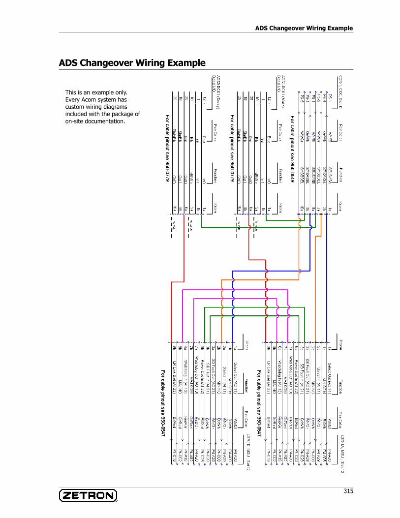
315
ADS Changeover Wiring Example
ADS Changeover Wiring Example
This is an example only. Every Acom system has custom wiring diagrams included with the package of on-site documentation.
Changeover Control
316 025-9574E
Forcing a Changeover
• A technician can force a changeover using IMS (see “Change Over” in the “Tools Menu” section of Acom Software Installation and Configuration, P/N 025-9529). Alternatively, a technician can force a changeover to an ALS by removing the front edge connector of the MSU card. These are the preferred methods to cause a changeover because they are the least disruptive.
• Incorrect wiring of the changeover signaling between the CCC and MSU may cause the subracks to switch continuously between the A and B system. This could happen if both racks have Watchdog and Standby faults active. Check your changeover wiring diagrams against the actual wiring in the Krone blocks.
• If the ALS never switches to the other sub rack even though a Watchdog failure has been triggered, the sub rack may be automatically acknowledging the alarms, check the mapping for the “Alarms ACK’d” output alarm in IMS (see “Alarms” in Acom Software Installation and Configuration, P/N 025-9529).
• If the ALS will not switch to the other subrack even though it has no alarms and the Watchdog has triggered on the active rack, it may be caused by a lack of confidence that the other rack is okay because of a problem with the SYSSEL output of the CCC card is pulled low by an unpowered DS3 Switch alarm I/O. Make sure the backbone switch alarms are biased by providing an external –48vdc reference. It may also be caused by the Watchdog alarm not being seen at the other subrack, the Watchdog input should normally be active. The OK alarm should be normally inactive.
Cloning an ALS
This section provides instructions for a Zetron Certified Acom technician to clone the ALS configuration from the main rack to the backup. Cloning the main configuration into the backup is a fast way to copy your changes to the standby ALS and keep both racks in sync. It is assumed that both ALSs have identical cards.
Equipment• Straight through RS-232 serial cable (DB9 to DB9)• Computer with IMS installed
Warning! If you change over using IMS, be certain to set “Mode” back to “Automatic”. Leaving this in manual mode will prevent an ALS from taking control in the event of a failure.
STOP
317
Cloning an ALS
Procedure1. Connect to the MCU3 connector X13 of the “Main” ALS using a straight-through
RS-232 cable.2. Start IMS and choose Communications-Connect from the IMS menu to connect.
Enter the network address of the main sub rack when prompted.3. Once connected, click File, Save to Disk from the IMS menu.4. Disconnect from the “Main” ALS and move the RS-232 cable from the “Main” to
the “Standby” ALS.5. From the IMS menu, click File, Load from Disk, and select the file you
previously saved from the “Main” ALS.6. The only options that should be different between the “Main” and “Standby” ALS
are the Sub-rack Address and External Clocking. Click Configure, Subrack Address from the IMS menu. Set the option to Standby and click Save.
7. Choose File, Update to Rack from the IMS menu to transfer the configuration to the ALS.
8. Reset the “Standby” ALS to finalize the changes.

Changeover Control
318 025-9574E
319
Preventative Maintenance
This chapter provides recommended preventative maintenance tips for an Acom system.
Check for Faults
The most important preventative maintenance you can do for your Acom system is to watch for faults and alarms. There are many faults that can occur that do not cause a loss of service. You can identify these issues using the IMS fault logs, the IMS alarm displays, and the LEDs associated with the equipment.
LEDs
The LEDs on the front of the equipment may be the first thing that makes you aware of an issue. On a periodic basis, walk by the common control electronics and check for any red, yellow, or amber LEDs that might indicate a problem. The LEDs may direct you to check the alarms of the associated device. Refer to the chapter Hardware Components on page 73 for a detailed description of the system LEDs.
Alarms
The IMS Terminal application can give you a high-level summary of the alarms in the system. While it does not include alarms that have come and gone, it does show devices with active alarms. Once the alarming device(s) have been identified, you could dive deeper into the specific input alarms or check the fault logs. Consult the chapter Appendix C: Alarms on page 371 for a detailed description of the input alarm definitions. Consult the chapter Troubleshooting on page 325 for a list of error messages and their causes.
Fault logs
The IMS fault logs should be checked on a periodic basis to monitor past alarms. If an alarm came and went before you could look at the alarms, the fault logs would still provide a history of when the alarm was active and inactive. Compare the fault logs against your maintenance records and flag anything that can’t be explained. Consult the section IMS Fault Logs on page 373 for a detailed description of the fault log messages.

Preventative Maintenance
320 025-9574E
Backups
Creating current backups of the system’s configuration is critical to recovering from a failure quickly. Make backups whenever the configuration changes.
Full Backups
Make full backups of the computer on a regular basis. A full computer backup can be quickly restored, simplifying the recovery process. It may be possible to automate backups.
IMS Backup
When changing the configuration of an Acom device such as a Acom Console Unit, save the configuration to disk on the maintenance terminal. Backup the IMS Terminal folder C:\Program Files\Zetron\IMS Terminal\ on a regular basis to archive the configurations off the server.
ACS Backup
Backup the latest copy of your ACS configuration by copying the entire C:\Program Files\Zetron\ACS\ folder to disk or other backup medium. This only needs be done for one position.
Standby Backup
Backing up also means copying the system configuration between the main and standby subracks. Any changes you make to the system A racks should be duplicated or cloned on the system B racks. Consult the section Cloning an ALS on page 316 for instructions on cloning an ALS.
Maintenance Log
When performing maintenance, changes, upgrades, or troubleshooting the system, make a record of the date and time with a short description of the action taken. Note in the log when backups are made. Note intermittent symptoms and any Zetron trouble ticket numbers you received as part of a trouble call. The maintenance log should be kept in the equipment room accessible to you.
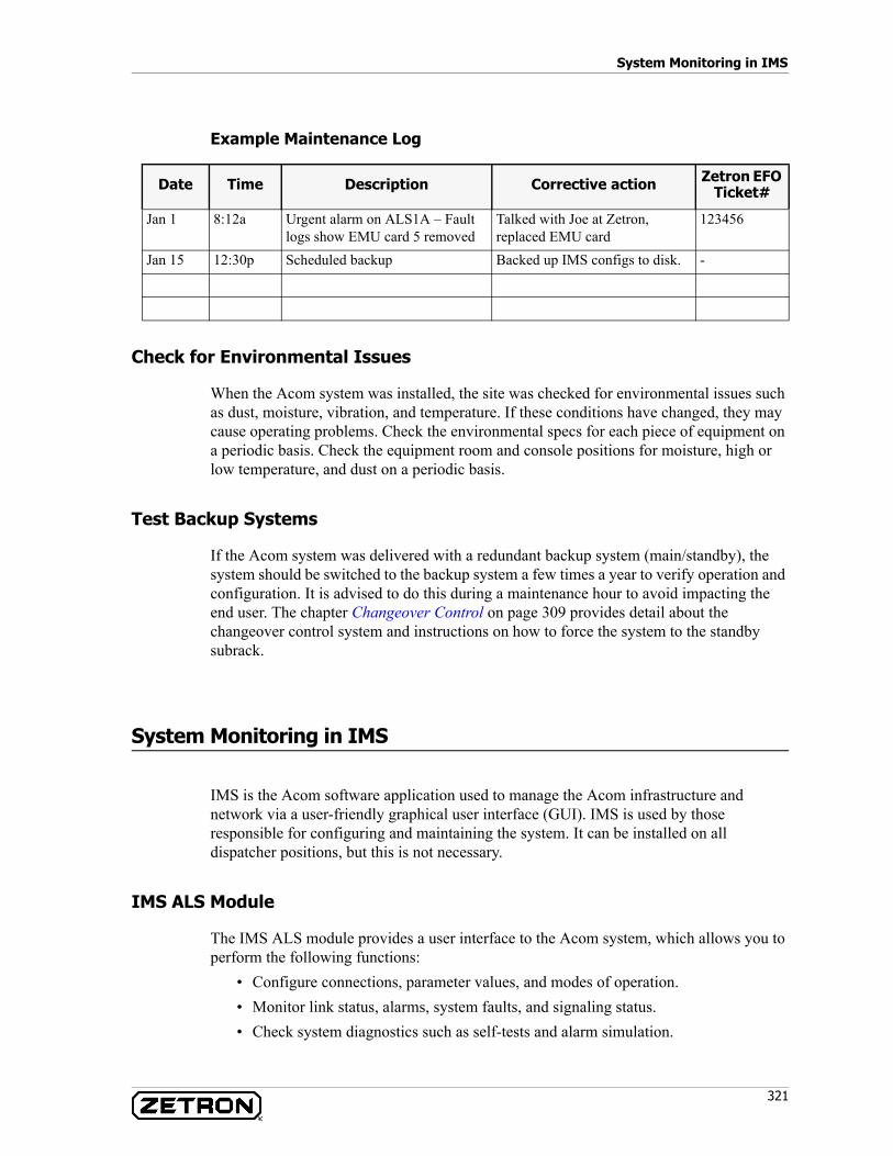
321
System Monitoring in IMS
Example Maintenance Log
Check for Environmental Issues
When the Acom system was installed, the site was checked for environmental issues such as dust, moisture, vibration, and temperature. If these conditions have changed, they may cause operating problems. Check the environmental specs for each piece of equipment on a periodic basis. Check the equipment room and console positions for moisture, high or low temperature, and dust on a periodic basis.
Test Backup Systems
If the Acom system was delivered with a redundant backup system (main/standby), the system should be switched to the backup system a few times a year to verify operation and configuration. It is advised to do this during a maintenance hour to avoid impacting the end user. The chapter Changeover Control on page 309 provides detail about the changeover control system and instructions on how to force the system to the standby subrack.
System Monitoring in IMS
IMS is the Acom software application used to manage the Acom infrastructure and network via a user-friendly graphical user interface (GUI). IMS is used by those responsible for configuring and maintaining the system. It can be installed on all dispatcher positions, but this is not necessary.
IMS ALS Module
The IMS ALS module provides a user interface to the Acom system, which allows you to perform the following functions:
• Configure connections, parameter values, and modes of operation.• Monitor link status, alarms, system faults, and signaling status.• Check system diagnostics such as self-tests and alarm simulation.
Date Time Description Corrective action Zetron EFO Ticket#
Jan 1 8:12a Urgent alarm on ALS1A – Fault logs show EMU card 5 removed
Talked with Joe at Zetron, replaced EMU card
123456
Jan 15 12:30p Scheduled backup Backed up IMS configs to disk. -
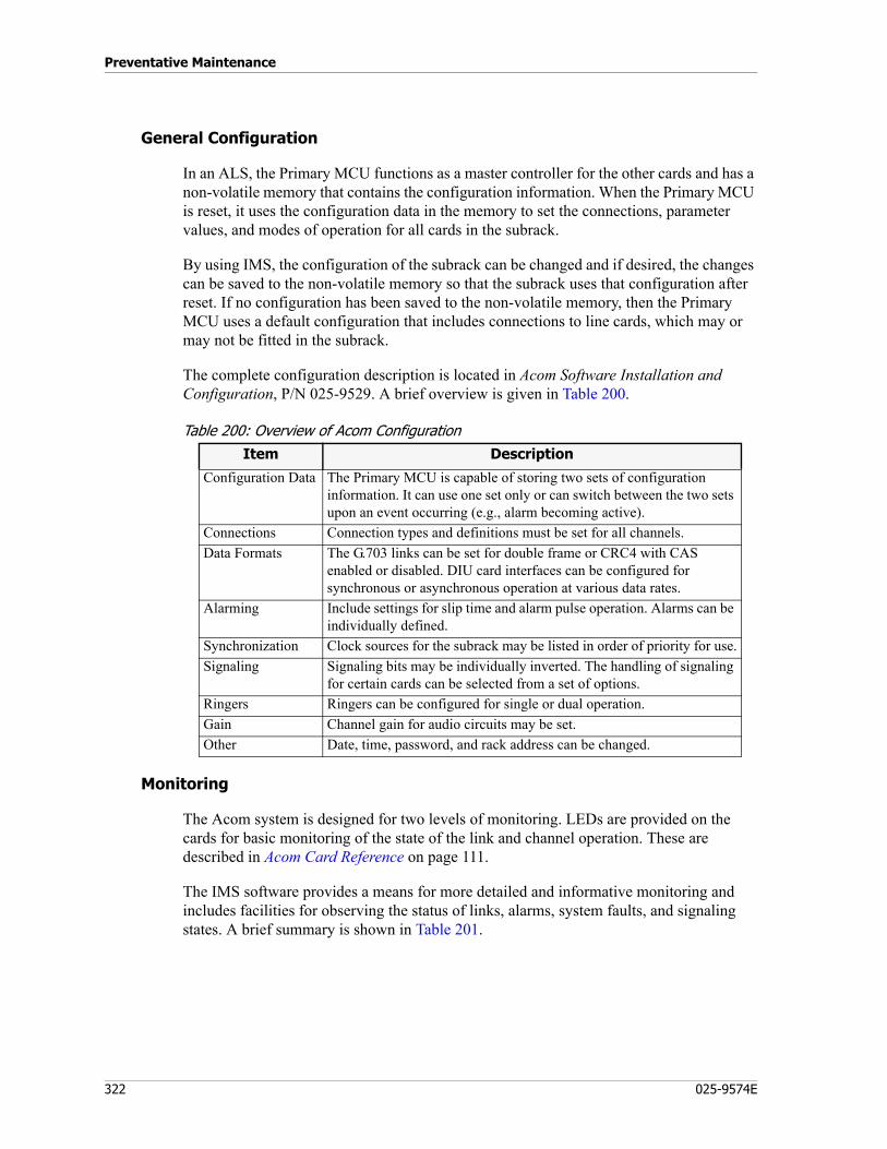
Preventative Maintenance
322 025-9574E
General Configuration
In an ALS, the Primary MCU functions as a master controller for the other cards and has a non-volatile memory that contains the configuration information. When the Primary MCU is reset, it uses the configuration data in the memory to set the connections, parameter values, and modes of operation for all cards in the subrack.
By using IMS, the configuration of the subrack can be changed and if desired, the changes can be saved to the non-volatile memory so that the subrack uses that configuration after reset. If no configuration has been saved to the non-volatile memory, then the Primary MCU uses a default configuration that includes connections to line cards, which may or may not be fitted in the subrack.
The complete configuration description is located in Acom Software Installation and Configuration, P/N 025-9529. A brief overview is given in Table 200.
Table 200: Overview of Acom Configuration
Monitoring
The Acom system is designed for two levels of monitoring. LEDs are provided on the cards for basic monitoring of the state of the link and channel operation. These are described in Acom Card Reference on page 111.
The IMS software provides a means for more detailed and informative monitoring and includes facilities for observing the status of links, alarms, system faults, and signaling states. A brief summary is shown in Table 201.
Item Description
Configuration Data The Primary MCU is capable of storing two sets of configuration information. It can use one set only or can switch between the two sets upon an event occurring (e.g., alarm becoming active).
Connections Connection types and definitions must be set for all channels.Data Formats The G.703 links can be set for double frame or CRC4 with CAS
enabled or disabled. DIU card interfaces can be configured for synchronous or asynchronous operation at various data rates.
Alarming Include settings for slip time and alarm pulse operation. Alarms can be individually defined.
Synchronization Clock sources for the subrack may be listed in order of priority for use.Signaling Signaling bits may be individually inverted. The handling of signaling
for certain cards can be selected from a set of options.Ringers Ringers can be configured for single or dual operation.Gain Channel gain for audio circuits may be set.Other Date, time, password, and rack address can be changed.
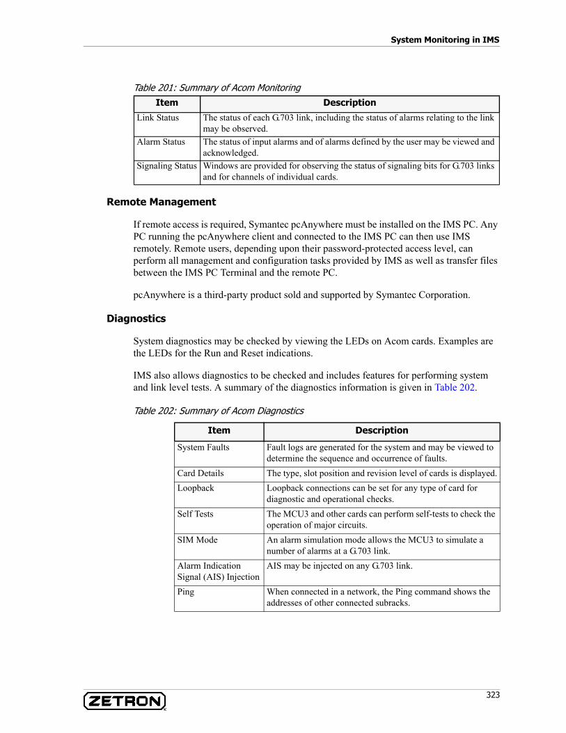
323
System Monitoring in IMS
Table 201: Summary of Acom Monitoring
Remote Management
If remote access is required, Symantec pcAnywhere must be installed on the IMS PC. Any PC running the pcAnywhere client and connected to the IMS PC can then use IMS remotely. Remote users, depending upon their password-protected access level, can perform all management and configuration tasks provided by IMS as well as transfer files between the IMS PC Terminal and the remote PC.
pcAnywhere is a third-party product sold and supported by Symantec Corporation.
Diagnostics
System diagnostics may be checked by viewing the LEDs on Acom cards. Examples are the LEDs for the Run and Reset indications.
IMS also allows diagnostics to be checked and includes features for performing system and link level tests. A summary of the diagnostics information is given in Table 202.
Table 202: Summary of Acom Diagnostics
Item Description
Link Status The status of each G.703 link, including the status of alarms relating to the link may be observed.
Alarm Status The status of input alarms and of alarms defined by the user may be viewed and acknowledged.
Signaling Status Windows are provided for observing the status of signaling bits for G.703 links and for channels of individual cards.
Item Description
System Faults Fault logs are generated for the system and may be viewed to determine the sequence and occurrence of faults.
Card Details The type, slot position and revision level of cards is displayed.Loopback Loopback connections can be set for any type of card for
diagnostic and operational checks. Self Tests The MCU3 and other cards can perform self-tests to check the
operation of major circuits. SIM Mode An alarm simulation mode allows the MCU3 to simulate a
number of alarms at a G.703 link. Alarm Indication Signal (AIS) Injection
AIS may be injected on any G.703 link.
Ping When connected in a network, the Ping command shows the addresses of other connected subracks.
Preventative Maintenance
324 025-9574E
Performance Testing and Troubleshooting
The Acom system features a facility to monitor and record transmission performance of the G.703 links using IMS. The parameters monitored include No Signal (NOS), Alarm Indication Signal (AIS), Loss of Synchronization (LOS), remote alarm and slip detection. The event log also records the statistical performance of the G.703 data stream, recording HDB3 code violations, CRC-4 error counts, and an ongoing measure of the bit error rate (BER) of the data.
A major feature provided by this system is the capability to perform internal loopbacks in the various signal paths. Loopbacks are used during commissioning and fault finding. By creating loops on signal paths it is possible to check the integrity of a channel from a given point in the system. To set a loopback, see “Loopback” in Acom Software Installation and Configuration, P/N 025-9529.
Installation and Configuration References
Additional topics related to Acom maintenance are the Installation and Configuration instructions described in the following documents:
Acom Software Installation and Configuration (P/N 025-9529)Acom Console Software Operation (P/N 025-9530)
General Troubleshooting
325
Troubleshooting
General Troubleshooting
Use the following general methods to detect and identify problems.
Gather symptoms by running a functional test and checking for alarms and faults.
Other symptoms may arise if you exercise the system. These symptoms may help you find the source of the problem. Check fault logs, system alarms, and LEDs, as they may lead you to the solution.
What has changed?
Ask yourself and others what has changed with the system that might have caused this. For example, recent configuration updates.
Reset the associated device
If you can, reset the associated Acom Console Unit, ALS, or ADS. If your system is redundant, you may not lose any functionality. While this does not help you understand what was wrong, it may correct the fault very quickly.
Isolate
Break the problem into blocks and isolate them. Can you isolate the problem to one position? One loop? A particular ADS? Is it common to a single line or circuit? A group of lines shared by a line card?
Switch to the backup system and retest; if the problem is now resolved, it may have been localized to the main system. Once you have isolated a problem, understanding what has caused it becomes easier.
Troubleshooting
326 025-9574E
Substitute
Once you have isolated the issue, try substituting a spare. Switching to the standby system is a method of substitution. Substitution can help you isolate problems as well.
Call for help
Zetron technical support is available 24/7. Your support contract will determine if support is free or requires a credit card. Please have your System ID ready when you call (the ID number is often found on the front of the Zetron cabinets).
For contact information, see http://www.zetron.com.
Specific Troubleshooting
Audio Problems on page 326
Console Problems on page 327
Other Problems on page 329
Audio Problems
Incorrect Audio or No Audio
There is no transmit audio from one position; all other positions are fine on page 329
One line has no transmit audio on all positions on page 330
Users cannot hear selected lines in the handset/headset on one console only on page 330
There is no receive audio from a monitored line on one console only on page 330
There is no audio from a line on any console on page 331
Selected or monitored lines do not present parallel operator transmit audio, only receive audio on page 333
Selected lines do not appear in the select speaker on page 334
Select audio does not appear in the select speaker on page 337
Monitored or selected lines are unmonitored or unselected by themselves on page 344
327
Specific Troubleshooting
Mute Not Working
Some functions like “Ring Mute” and “Mute All” time out on page 334
The “All Mute” or “Monitor Mute” function does not completely mute the receive audio on page 334
Volume and Audio Quality
Adjacent operators are too loud in my speakers on page 345
The level of the monitored channels cannot be changed on page 335
Crackle or static sound at position on page 344
Noise in speaker, clicking/ticking sound at times. Happens the most during logon on page 344
60hz buzz in speakers. on page 344
Hearing conversation from an adjacent position in headset or speaker on page 345
Console Problems
General
The ACS crashes on startup with a Windows error when run from a Windows login without administrative permissions on page 338
Cannot exit to Windows on page 332
Cannot log off ACS on page 332
Cannot select a radio channel on the ACS, console plays a “Bing” sound when line clicked on page 332
The ACS does not show Tx indication (yellow text) on radio line on page 332
The ACS did not bring up the dial pad, the button is stuck in the depressed position on page 333
The ACS popup forms, such as dial pad, monitor, and conference, are blocking access to other buttons and cannot be moved on page 333
The time on the console is wrong on page 335
All lines on the ACS gray out during operation on page 335
Intercom fails and ACS plays a “Bing” without connecting to selected console on page 345

Troubleshooting
328 025-9574E
Integrator IRR
IntegratorIRR is not recording messages on page 342
IntIRR is recording blank (silent) messages on page 342
Popup message “IRR failed to record” on page 343
IRR not working. Message: “irr.exe has generated errors and will be closed by Windows, you will need to restart this program, an error log is being created” on page 343
IntegratorIRR failure “the currently recording message has exceeded the imposed size limit for a single recorded message. Ensure that your record control configuration parameters are optimally set to avoid recording messages that are too large” on page 343
Console Error Messages
The console displays “Heartbeat Timeout” message on page 331
The console displays “No Audio Interface” message on page 331
The status bar says “SOMETHING.WAV does not exist” on page 333
The Status bar shows “Console Waiting ##” on page 337
The ACS pops up a dialog “Cannot open quick dial database” and does not start on page 338
The ACS pops up a dialog “Line key XX type does not match physical line XX” when loading the form file on page 338
The ACS logon dialog box shows “Fail Over” mode instead of “Online” on page 340
The ACS logon dialog box shows “Offline” mode instead of “Online” on page 340
Popup message “IRR failed to record” on page 343
IRR not working. Message: “irr.exe has generated errors and will be closed by Windows, you will need to restart this program, an error log is being created” on page 343
IntegratorIRR failure “the currently recording message has exceeded the imposed size limit for a single recorded message. Ensure that your record control configuration parameters are optimally set to avoid recording messages that are too large” on page 343
Missing or Unavailable Functions
There are missing monitors in the Monitor selection popup. MS1/MS2/MS3/MS4 are gray and not selectable on page 336
The Dial Pad does not have a Send button when an ISDN line is selected / Cannot make calls on ISDN lines on page 337
329
Recommended Actions
The Alpha Search button is missing from the Dial Pad on page 338
The Broadcast and Announce buttons are missing from the Intercom popup on page 339
Headset/Handset/Footswitch
The foot switch does not key the selected radio channel on page 339
The handset/headset does not key the selected radio channel, does not show yellow text on line on page 339
Other Problems
The phone line turns green but will not ring for inbound calls on page 334
The ACS is slow to respond to button presses such as line selection or PTT on page 336
Right-clicking on a radio channel causes a popup dialog to appear instead of causing an instant transmit on page 340
The passwords for the ACS have been lost or forgotten on page 341
The passwords for the ACU, DCU, or MCU have been lost or forgotten on page 341
Hunt Groups are not working; a line is not selected on page 346
Recommended Actions
There is no transmit audio from one position; all other positions are fine
Possible Cause Recommended Action
Handset not detected. If the Status Panel in ACS shows “Speaker”, the handset is not detected. Check its connection and try a different handset. The ACS uses the microphone current to detect the headset/handset.
Console in Demo mode. Check status bar that console is “Online”. May have gone into demo mode because of communications errors.
Microphone is muted. Check the Mute function. If it is flashing, the operator’s microphone is muted.
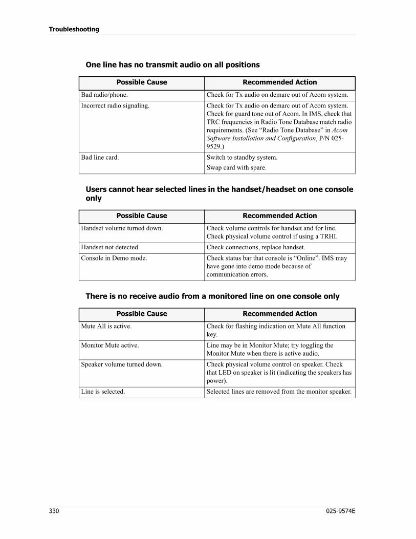
Troubleshooting
330 025-9574E
One line has no transmit audio on all positions
Users cannot hear selected lines in the handset/headset on one console only
There is no receive audio from a monitored line on one console only
Possible Cause Recommended Action
Bad radio/phone. Check for Tx audio on demarc out of Acom system.Incorrect radio signaling. Check for Tx audio on demarc out of Acom system.
Check for guard tone out of Acom. In IMS, check that TRC frequencies in Radio Tone Database match radio requirements. (See “Radio Tone Database” in Acom Software Installation and Configuration, P/N 025-9529.)
Bad line card. Switch to standby system.Swap card with spare.
Possible Cause Recommended Action
Handset volume turned down. Check volume controls for handset and for line. Check physical volume control if using a TRHI.
Handset not detected. Check connections, replace handset.Console in Demo mode. Check status bar that console is “Online”. IMS may
have gone into demo mode because of communication errors.
Possible Cause Recommended Action
Mute All is active. Check for flashing indication on Mute All function key.
Monitor Mute active. Line may be in Monitor Mute; try toggling the Monitor Mute when there is active audio.
Speaker volume turned down. Check physical volume control on speaker. Check that LED on speaker is lit (indicating the speakers has power).
Line is selected. Selected lines are removed from the monitor speaker.
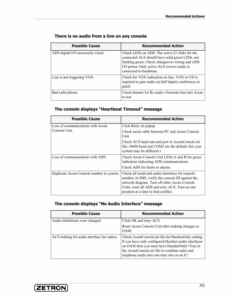
331
Recommended Actions
There is no audio from a line on any console
The console displays “Heartbeat Timeout” message
The console displays “No Audio Interface” message
Possible Cause Recommended Action
ADS digital I/O incorrectly wired. Check LEDs on ADS. The active E1 links for the connected ALS should have solid green LEDs, not flashing green. Check changeover wiring and ADS I/O power. Only active ALS receive audio is connected to backbone.
Line is not triggering VOX. Check for VOX indication on line. VOX or CD is required to gate audio on half duplex conference or patch.
Bad radio/phone. Check demarc for Rx audio. Generate tone into Acom to test.
Possible Cause Recommended Action
Loss of communications with Acom Console Unit.
Click Retry on popup.Check serial cable between PC and Acom Console Unit.Check ACS baud rate and port in AcomConsole.ini file. (9600 baud and COM2 are the default, but your system may be different.)
Loss of communications with ADS. Check Acom Console Unit LEDs A and B for green indication indicating ADS communications.Check ADS for faults or alarms.
Duplicate Acom Console number in system. Check all serial and audio interfaces for console number. In IMS, verify the console ID against the network diagram. Turn off other Acom Console Units, reset all ADS and retry ACS. Turn on one position at a time to find conflict.
Possible Cause Recommended Action
Audio definitions were changed. Click OK and retry ACS.Reset Acom Console Unit after making changes to OAM.
ACS looking for audio interface for radios. Check AcomConsole.ini file for HandsetOnly setting. If you have only configured Headset audio interfaces on OAM then you must have HandsetOnly=True in the AcomConsole.ini file to combine radio and telephone audio into one time slot on an E1.
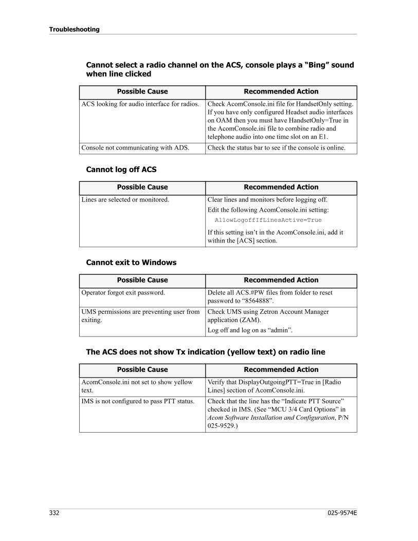
Troubleshooting
332 025-9574E
Cannot select a radio channel on the ACS, console plays a “Bing” sound when line clicked
Cannot log off ACS
Cannot exit to Windows
The ACS does not show Tx indication (yellow text) on radio line
Possible Cause Recommended Action
ACS looking for audio interface for radios. Check AcomConsole.ini file for HandsetOnly setting. If you have only configured Headset audio interfaces on OAM then you must have HandsetOnly=True in the AcomConsole.ini file to combine radio and telephone audio into one time slot on an E1.
Console not communicating with ADS. Check the status bar to see if the console is online.
Possible Cause Recommended Action
Lines are selected or monitored. Clear lines and monitors before logging off.Edit the following AcomConsole.ini setting:AllowLogoffIfLinesActive=True
If this setting isn’t in the AcomConsole.ini, add it within the [ACS] section.
Possible Cause Recommended Action
Operator forgot exit password. Delete all ACS.#PW files from folder to reset password to “8564888”.
UMS permissions are preventing user from exiting.
Check UMS using Zetron Account Manager application (ZAM).Log off and log on as “admin”.
Possible Cause Recommended Action
AcomConsole.ini not set to show yellow text.
Verify that DisplayOutgoingPTT=True in [Radio Lines] section of AcomConsole.ini.
IMS is not configured to pass PTT status. Check that the line has the “Indicate PTT Source” checked in IMS. (See “MCU 3/4 Card Options” in Acom Software Installation and Configuration, P/N 025-9529.)
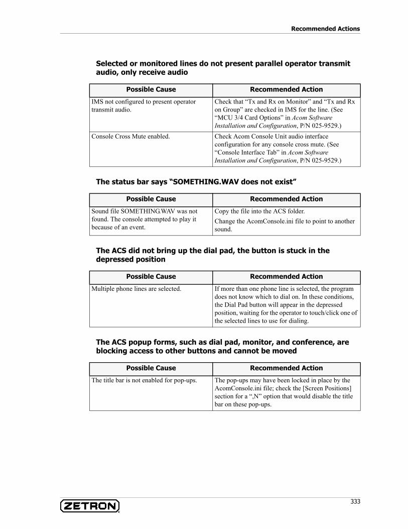
333
Recommended Actions
Selected or monitored lines do not present parallel operator transmit audio, only receive audio
The status bar says “SOMETHING.WAV does not exist”
The ACS did not bring up the dial pad, the button is stuck in the depressed position
The ACS popup forms, such as dial pad, monitor, and conference, are blocking access to other buttons and cannot be moved
Possible Cause Recommended Action
IMS not configured to present operator transmit audio.
Check that “Tx and Rx on Monitor” and “Tx and Rx on Group” are checked in IMS for the line. (See “MCU 3/4 Card Options” in Acom Software Installation and Configuration, P/N 025-9529.)
Console Cross Mute enabled. Check Acom Console Unit audio interface configuration for any console cross mute. (See “Console Interface Tab” in Acom Software Installation and Configuration, P/N 025-9529.)
Possible Cause Recommended Action
Sound file SOMETHING.WAV was not found. The console attempted to play it because of an event.
Copy the file into the ACS folder.Change the AcomConsole.ini file to point to another sound.
Possible Cause Recommended Action
Multiple phone lines are selected. If more than one phone line is selected, the program does not know which to dial on. In these conditions, the Dial Pad button will appear in the depressed position, waiting for the operator to touch/click one of the selected lines to use for dialing.
Possible Cause Recommended Action
The title bar is not enabled for pop-ups. The pop-ups may have been locked in place by the AcomConsole.ini file; check the [Screen Positions] section for a “,N” option that would disable the title bar on these pop-ups.
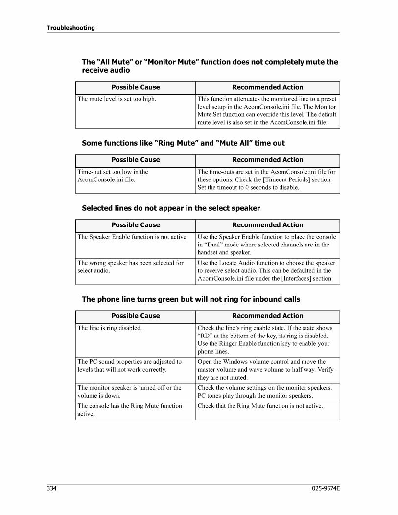
Troubleshooting
334 025-9574E
The “All Mute” or “Monitor Mute” function does not completely mute the receive audio
Some functions like “Ring Mute” and “Mute All” time out
Selected lines do not appear in the select speaker
The phone line turns green but will not ring for inbound calls
Possible Cause Recommended Action
The mute level is set too high. This function attenuates the monitored line to a preset level setup in the AcomConsole.ini file. The Monitor Mute Set function can override this level. The default mute level is also set in the AcomConsole.ini file.
Possible Cause Recommended Action
Time-out set too low in the AcomConsole.ini file.
The time-outs are set in the AcomConsole.ini file for these options. Check the [Timeout Periods] section. Set the timeout to 0 seconds to disable.
Possible Cause Recommended Action
The Speaker Enable function is not active. Use the Speaker Enable function to place the console in “Dual” mode where selected channels are in the handset and speaker.
The wrong speaker has been selected for select audio.
Use the Locate Audio function to choose the speaker to receive select audio. This can be defaulted in the AcomConsole.ini file under the [Interfaces] section.
Possible Cause Recommended Action
The line is ring disabled. Check the line’s ring enable state. If the state shows “RD” at the bottom of the key, its ring is disabled. Use the Ringer Enable function key to enable your phone lines.
The PC sound properties are adjusted to levels that will not work correctly.
Open the Windows volume control and move the master volume and wave volume to half way. Verify they are not muted.
The monitor speaker is turned off or the volume is down.
Check the volume settings on the monitor speakers. PC tones play through the monitor speakers.
The console has the Ring Mute function active.
Check that the Ring Mute function is not active.
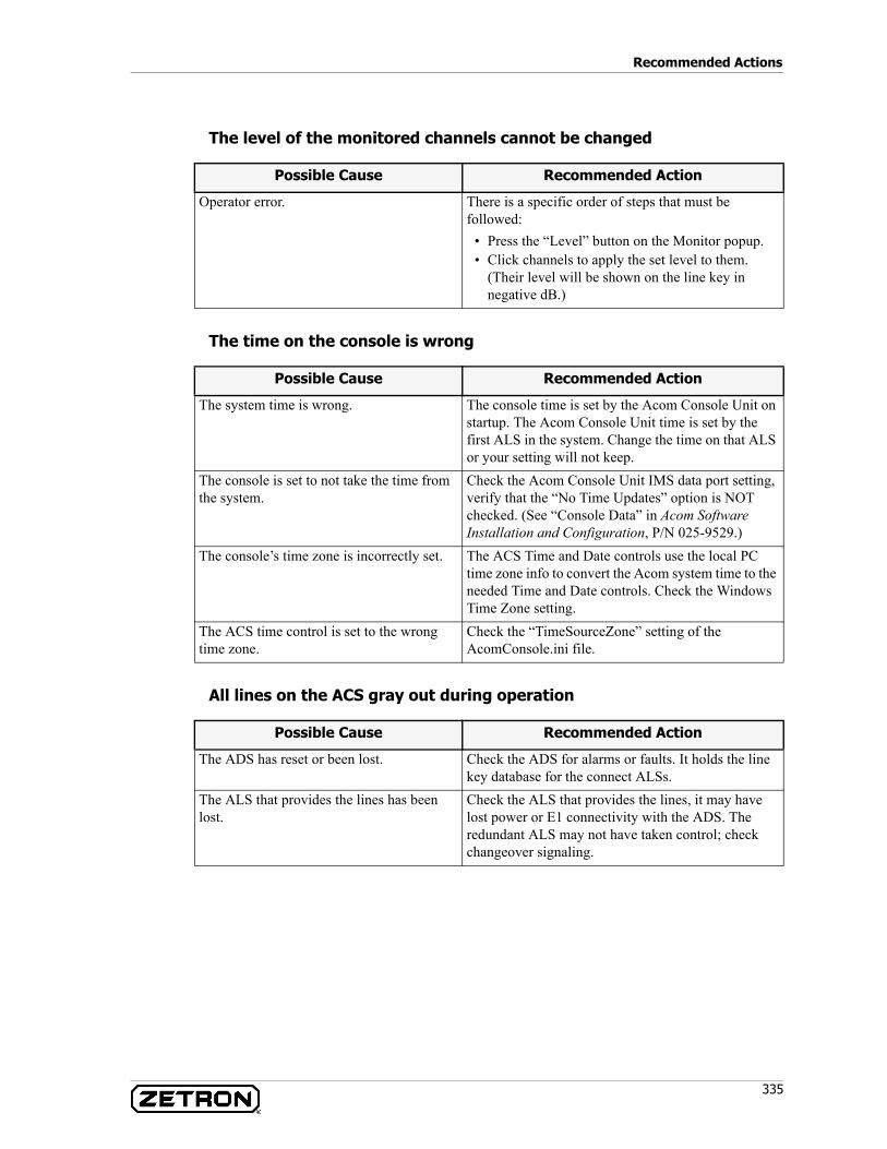
335
Recommended Actions
The level of the monitored channels cannot be changed
The time on the console is wrong
All lines on the ACS gray out during operation
Possible Cause Recommended Action
Operator error. There is a specific order of steps that must be followed:
• Press the “Level” button on the Monitor popup.• Click channels to apply the set level to them.
(Their level will be shown on the line key in negative dB.)
Possible Cause Recommended Action
The system time is wrong. The console time is set by the Acom Console Unit on startup. The Acom Console Unit time is set by the first ALS in the system. Change the time on that ALS or your setting will not keep.
The console is set to not take the time from the system.
Check the Acom Console Unit IMS data port setting, verify that the “No Time Updates” option is NOT checked. (See “Console Data” in Acom Software Installation and Configuration, P/N 025-9529.)
The console’s time zone is incorrectly set. The ACS Time and Date controls use the local PC time zone info to convert the Acom system time to the needed Time and Date controls. Check the Windows Time Zone setting.
The ACS time control is set to the wrong time zone.
Check the “TimeSourceZone” setting of the AcomConsole.ini file.
Possible Cause Recommended Action
The ADS has reset or been lost. Check the ADS for alarms or faults. It holds the line key database for the connect ALSs.
The ALS that provides the lines has been lost.
Check the ALS that provides the lines, it may have lost power or E1 connectivity with the ADS. The redundant ALS may not have taken control; check changeover signaling.
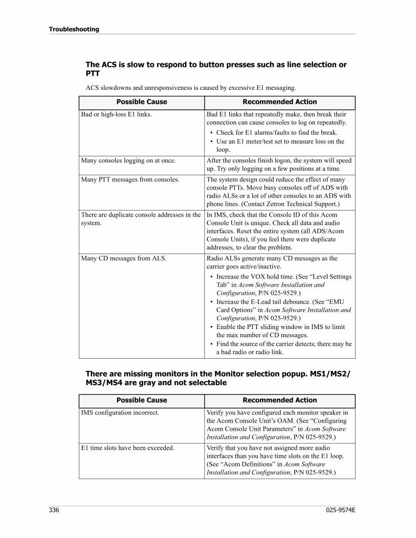
Troubleshooting
336 025-9574E
The ACS is slow to respond to button presses such as line selection or PTT
ACS slowdowns and unresponsiveness is caused by excessive E1 messaging.
There are missing monitors in the Monitor selection popup. MS1/MS2/MS3/MS4 are gray and not selectable
Possible Cause Recommended Action
Bad or high-loss E1 links. Bad E1 links that repeatedly make, then break their connection can cause consoles to log on repeatedly.
• Check for E1 alarms/faults to find the break.• Use an E1 meter/test set to measure loss on the
loop.Many consoles logging on at once. After the consoles finish logon, the system will speed
up. Try only logging on a few positions at a time.Many PTT messages from consoles. The system design could reduce the effect of many
console PTTs. Move busy consoles off of ADS with radio ALSs or a lot of other consoles to an ADS with phone lines. (Contact Zetron Technical Support.)
There are duplicate console addresses in the system.
In IMS, check that the Console ID of this Acom Console Unit is unique. Check all data and audio interfaces. Reset the entire system (all ADS/Acom Console Units), if you feel there were duplicate addresses, to clear the problem.
Many CD messages from ALS. Radio ALSs generate many CD messages as the carrier goes active/inactive.
• Increase the VOX hold time. (See “Level Settings Tab” in Acom Software Installation and Configuration, P/N 025-9529.)
• Increase the E-Lead tail debounce. (See “EMU Card Options” in Acom Software Installation and Configuration, P/N 025-9529.)
• Enable the PTT sliding window in IMS to limit the max number of CD messages.
• Find the source of the carrier detects; there may be a bad radio or radio link.
Possible Cause Recommended Action
IMS configuration incorrect. Verify you have configured each monitor speaker in the Acom Console Unit’s OAM. (See “Configuring Acom Console Unit Parameters” in Acom Software Installation and Configuration, P/N 025-9529.)
E1 time slots have been exceeded. Verify that you have not assigned more audio interfaces than you have time slots on the E1 loop. (See “Acom Definitions” in Acom Software Installation and Configuration, P/N 025-9529.)
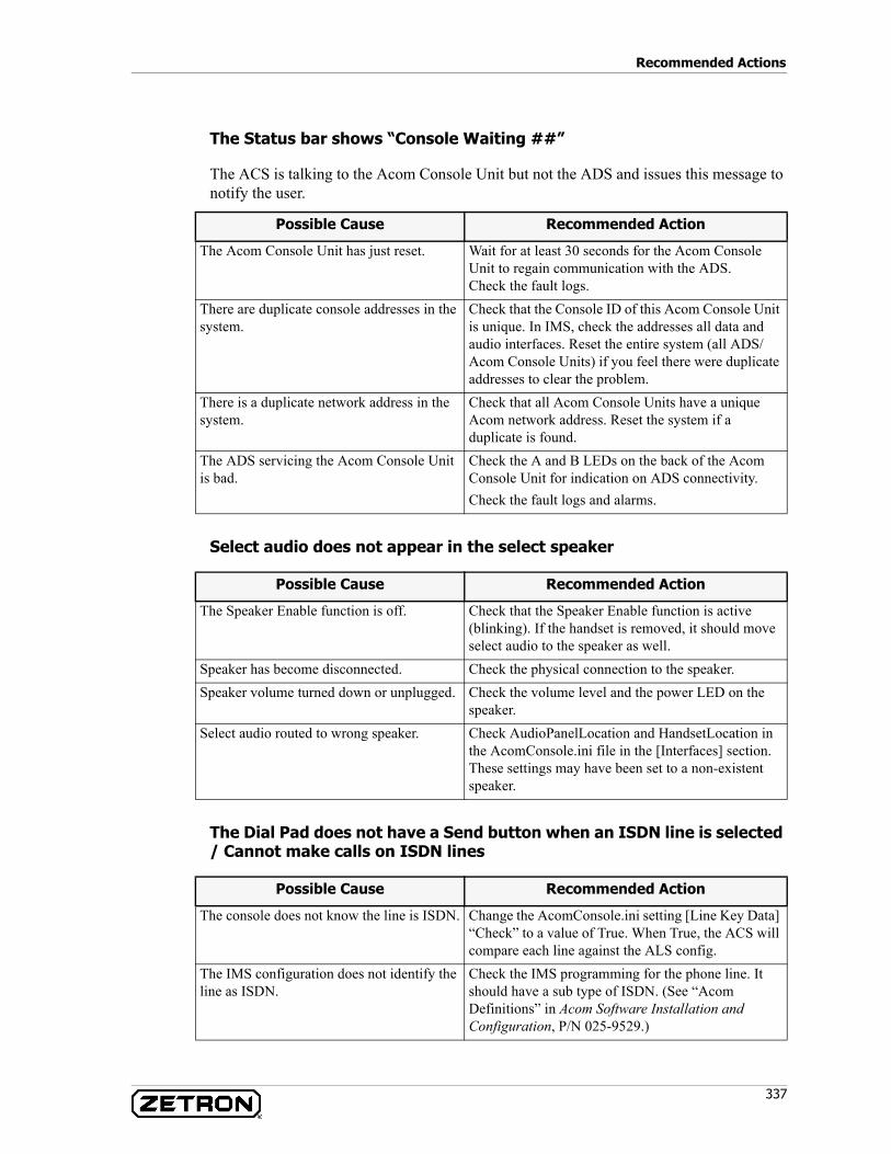
337
Recommended Actions
The Status bar shows “Console Waiting ##”
The ACS is talking to the Acom Console Unit but not the ADS and issues this message to notify the user.
Select audio does not appear in the select speaker
The Dial Pad does not have a Send button when an ISDN line is selected / Cannot make calls on ISDN lines
Possible Cause Recommended Action
The Acom Console Unit has just reset. Wait for at least 30 seconds for the Acom Console Unit to regain communication with the ADS. Check the fault logs.
There are duplicate console addresses in the system.
Check that the Console ID of this Acom Console Unit is unique. In IMS, check the addresses all data and audio interfaces. Reset the entire system (all ADS/Acom Console Units) if you feel there were duplicate addresses to clear the problem.
There is a duplicate network address in the system.
Check that all Acom Console Units have a unique Acom network address. Reset the system if a duplicate is found.
The ADS servicing the Acom Console Unit is bad.
Check the A and B LEDs on the back of the Acom Console Unit for indication on ADS connectivity.Check the fault logs and alarms.
Possible Cause Recommended Action
The Speaker Enable function is off. Check that the Speaker Enable function is active (blinking). If the handset is removed, it should move select audio to the speaker as well.
Speaker has become disconnected. Check the physical connection to the speaker.Speaker volume turned down or unplugged. Check the volume level and the power LED on the
speaker.Select audio routed to wrong speaker. Check AudioPanelLocation and HandsetLocation in
the AcomConsole.ini file in the [Interfaces] section. These settings may have been set to a non-existent speaker.
Possible Cause Recommended Action
The console does not know the line is ISDN. Change the AcomConsole.ini setting [Line Key Data] “Check” to a value of True. When True, the ACS will compare each line against the ALS config.
The IMS configuration does not identify the line as ISDN.
Check the IMS programming for the phone line. It should have a sub type of ISDN. (See “Acom Definitions” in Acom Software Installation and Configuration, P/N 025-9529.)
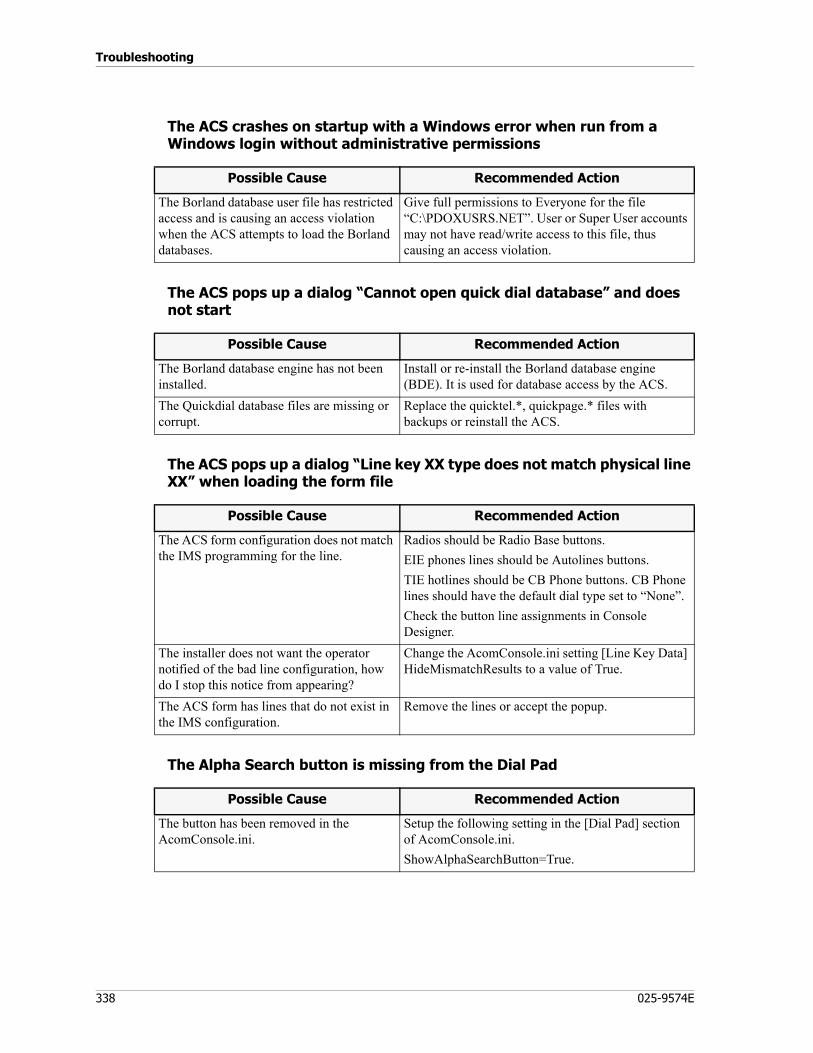
Troubleshooting
338 025-9574E
The ACS crashes on startup with a Windows error when run from a Windows login without administrative permissions
The ACS pops up a dialog “Cannot open quick dial database” and does not start
The ACS pops up a dialog “Line key XX type does not match physical line XX” when loading the form file
The Alpha Search button is missing from the Dial Pad
Possible Cause Recommended Action
The Borland database user file has restricted access and is causing an access violation when the ACS attempts to load the Borland databases.
Give full permissions to Everyone for the file “C:\PDOXUSRS.NET”. User or Super User accounts may not have read/write access to this file, thus causing an access violation.
Possible Cause Recommended Action
The Borland database engine has not been installed.
Install or re-install the Borland database engine (BDE). It is used for database access by the ACS.
The Quickdial database files are missing or corrupt.
Replace the quicktel.*, quickpage.* files with backups or reinstall the ACS.
Possible Cause Recommended Action
The ACS form configuration does not match the IMS programming for the line.
Radios should be Radio Base buttons.EIE phones lines should be Autolines buttons.TIE hotlines should be CB Phone buttons. CB Phone lines should have the default dial type set to “None”.Check the button line assignments in Console Designer.
The installer does not want the operator notified of the bad line configuration, how do I stop this notice from appearing?
Change the AcomConsole.ini setting [Line Key Data] HideMismatchResults to a value of True.
The ACS form has lines that do not exist in the IMS configuration.
Remove the lines or accept the popup.
Possible Cause Recommended Action
The button has been removed in the AcomConsole.ini.
Setup the following setting in the [Dial Pad] section of AcomConsole.ini.ShowAlphaSearchButton=True.
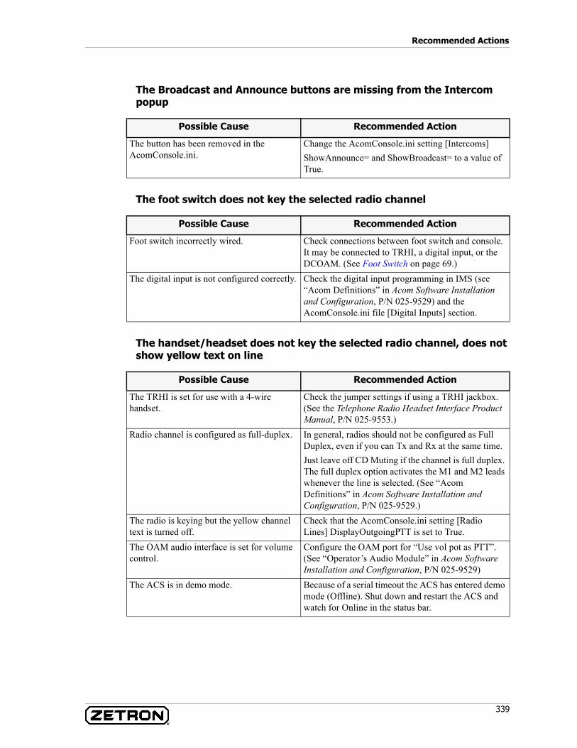
339
Recommended Actions
The Broadcast and Announce buttons are missing from the Intercom popup
The foot switch does not key the selected radio channel
The handset/headset does not key the selected radio channel, does not show yellow text on line
Possible Cause Recommended Action
The button has been removed in the AcomConsole.ini.
Change the AcomConsole.ini setting [Intercoms] ShowAnnounce= and ShowBroadcast= to a value of True.
Possible Cause Recommended Action
Foot switch incorrectly wired. Check connections between foot switch and console. It may be connected to TRHI, a digital input, or the DCOAM. (See Foot Switch on page 69.)
The digital input is not configured correctly. Check the digital input programming in IMS (see “Acom Definitions” in Acom Software Installation and Configuration, P/N 025-9529) and the AcomConsole.ini file [Digital Inputs] section.
Possible Cause Recommended Action
The TRHI is set for use with a 4-wire handset.
Check the jumper settings if using a TRHI jackbox. (See the Telephone Radio Headset Interface Product Manual, P/N 025-9553.)
Radio channel is configured as full-duplex. In general, radios should not be configured as Full Duplex, even if you can Tx and Rx at the same time.Just leave off CD Muting if the channel is full duplex. The full duplex option activates the M1 and M2 leads whenever the line is selected. (See “Acom Definitions” in Acom Software Installation and Configuration, P/N 025-9529.)
The radio is keying but the yellow channel text is turned off.
Check that the AcomConsole.ini setting [Radio Lines] DisplayOutgoingPTT is set to True.
The OAM audio interface is set for volume control.
Configure the OAM port for “Use vol pot as PTT”. (See “Operator’s Audio Module” in Acom Software Installation and Configuration, P/N 025-9529)
The ACS is in demo mode. Because of a serial timeout the ACS has entered demo mode (Offline). Shut down and restart the ACS and watch for Online in the status bar.
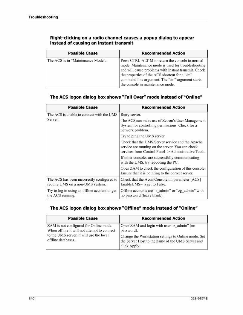
Troubleshooting
340 025-9574E
Right-clicking on a radio channel causes a popup dialog to appear instead of causing an instant transmit
The ACS logon dialog box shows “Fail Over” mode instead of “Online”
The ACS logon dialog box shows “Offline” mode instead of “Online”
Possible Cause Recommended Action
The ACS is in “Maintenance Mode”. Press CTRL-ALT-M to return the console to normal mode. Maintenance mode is used for troubleshooting and will cause problems with instant transmit. Check the properties of the ACS shortcut for a “/m” command line argument. The “/m” argument starts the console in maintenance mode.
Possible Cause Recommended Action
The ACS is unable to connect with the UMS Server.
Retry server.The ACS can make use of Zetron’s User Management System for controlling permissions. Check for a network problem.Try to ping the UMS server.Check that the UMS Server service and the Apache service are running on the server. You can check services from Control Panel -> Administrative Tools.If other consoles are successfully communicating with the UMS, try rebooting the PC.Open ZAM to check the configuration of this console. Ensure that it is pointing to the correct server.
The ACS has been incorrectly configured to require UMS on a non-UMS system.
Check that the AcomConsole.ini parameter [ACS] EnableUMS= is set to False.
Try to log in using an offline account to get the ACS running.
Offline accounts are “z_admin” or “zg_admin” with no password (leave blank).
Possible Cause Recommended Action
ZAM is not configured for Online mode. When offline it will not attempt to connect to the UMS server, it will use the local offline databases.
Open ZAM and login with user “z_admin” (no password).Change the Workstation settings to Online mode. Set the Server Host to the name of the UMS Server and click Apply.
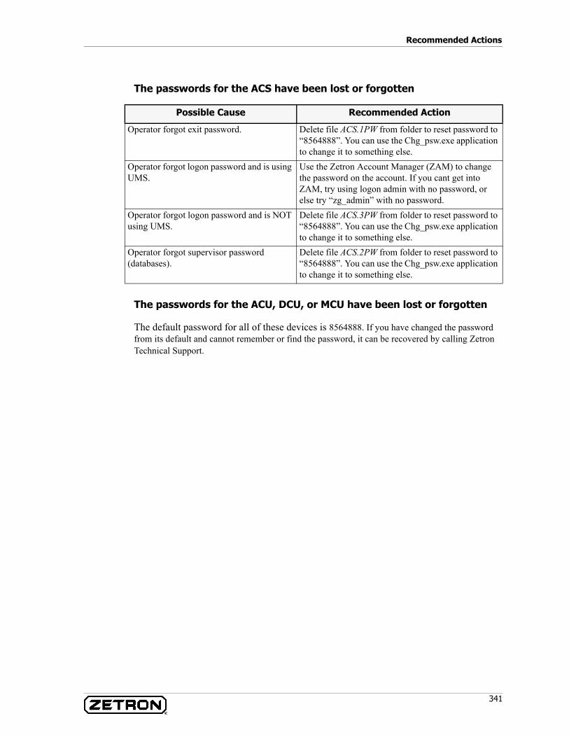
341
Recommended Actions
The passwords for the ACS have been lost or forgotten
The passwords for the ACU, DCU, or MCU have been lost or forgotten
The default password for all of these devices is 8564888. If you have changed the password from its default and cannot remember or find the password, it can be recovered by calling Zetron Technical Support.
Possible Cause Recommended Action
Operator forgot exit password. Delete file ACS.1PW from folder to reset password to “8564888”. You can use the Chg_psw.exe application to change it to something else.
Operator forgot logon password and is using UMS.
Use the Zetron Account Manager (ZAM) to change the password on the account. If you cant get into ZAM, try using logon admin with no password, or else try “zg_admin” with no password.
Operator forgot logon password and is NOT using UMS.
Delete file ACS.3PW from folder to reset password to “8564888”. You can use the Chg_psw.exe application to change it to something else.
Operator forgot supervisor password (databases).
Delete file ACS.2PW from folder to reset password to “8564888”. You can use the Chg_psw.exe application to change it to something else.
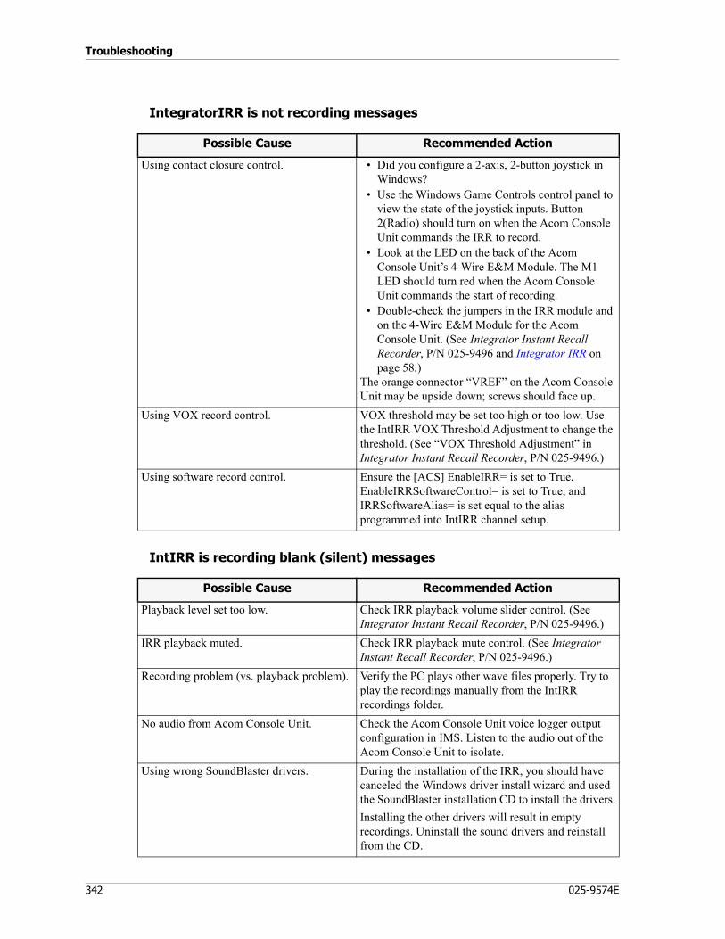
Troubleshooting
342 025-9574E
IntegratorIRR is not recording messages
IntIRR is recording blank (silent) messages
Possible Cause Recommended Action
Using contact closure control. • Did you configure a 2-axis, 2-button joystick in Windows?
• Use the Windows Game Controls control panel to view the state of the joystick inputs. Button 2(Radio) should turn on when the Acom Console Unit commands the IRR to record.
• Look at the LED on the back of the Acom Console Unit’s 4-Wire E&M Module. The M1 LED should turn red when the Acom Console Unit commands the start of recording.
• Double-check the jumpers in the IRR module and on the 4-Wire E&M Module for the Acom Console Unit. (See Integrator Instant Recall Recorder, P/N 025-9496 and Integrator IRR on page 58.)
The orange connector “VREF” on the Acom Console Unit may be upside down; screws should face up.
Using VOX record control. VOX threshold may be set too high or too low. Use the IntIRR VOX Threshold Adjustment to change the threshold. (See “VOX Threshold Adjustment” in Integrator Instant Recall Recorder, P/N 025-9496.)
Using software record control. Ensure the [ACS] EnableIRR= is set to True, EnableIRRSoftwareControl= is set to True, and IRRSoftwareAlias= is set equal to the alias programmed into IntIRR channel setup.
Possible Cause Recommended Action
Playback level set too low. Check IRR playback volume slider control. (See Integrator Instant Recall Recorder, P/N 025-9496.)
IRR playback muted. Check IRR playback mute control. (See Integrator Instant Recall Recorder, P/N 025-9496.)
Recording problem (vs. playback problem). Verify the PC plays other wave files properly. Try to play the recordings manually from the IntIRR recordings folder.
No audio from Acom Console Unit. Check the Acom Console Unit voice logger output configuration in IMS. Listen to the audio out of the Acom Console Unit to isolate.
Using wrong SoundBlaster drivers. During the installation of the IRR, you should have canceled the Windows driver install wizard and used the SoundBlaster installation CD to install the drivers.Installing the other drivers will result in empty recordings. Uninstall the sound drivers and reinstall from the CD.
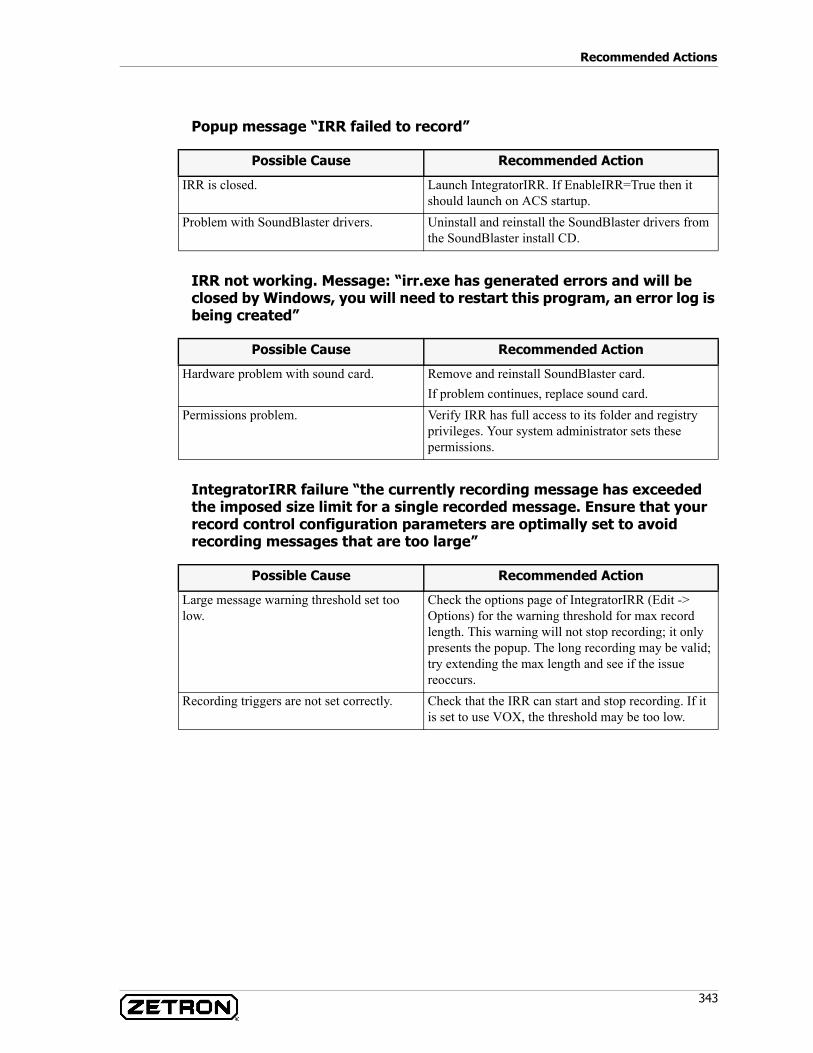
343
Recommended Actions
Popup message “IRR failed to record”
IRR not working. Message: “irr.exe has generated errors and will be closed by Windows, you will need to restart this program, an error log is being created”
IntegratorIRR failure “the currently recording message has exceeded the imposed size limit for a single recorded message. Ensure that your record control configuration parameters are optimally set to avoid recording messages that are too large”
Possible Cause Recommended Action
IRR is closed. Launch IntegratorIRR. If EnableIRR=True then it should launch on ACS startup.
Problem with SoundBlaster drivers. Uninstall and reinstall the SoundBlaster drivers from the SoundBlaster install CD.
Possible Cause Recommended Action
Hardware problem with sound card. Remove and reinstall SoundBlaster card.If problem continues, replace sound card.
Permissions problem. Verify IRR has full access to its folder and registry privileges. Your system administrator sets these permissions.
Possible Cause Recommended Action
Large message warning threshold set too low.
Check the options page of IntegratorIRR (Edit -> Options) for the warning threshold for max record length. This warning will not stop recording; it only presents the popup. The long recording may be valid; try extending the max length and see if the issue reoccurs.
Recording triggers are not set correctly. Check that the IRR can start and stop recording. If it is set to use VOX, the threshold may be too low.
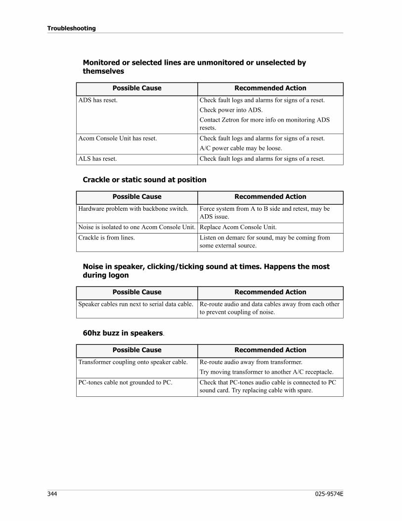
Troubleshooting
344 025-9574E
Monitored or selected lines are unmonitored or unselected by themselves
Crackle or static sound at position
Noise in speaker, clicking/ticking sound at times. Happens the most during logon
60hz buzz in speakers.
Possible Cause Recommended Action
ADS has reset. Check fault logs and alarms for signs of a reset.Check power into ADS.Contact Zetron for more info on monitoring ADS resets.
Acom Console Unit has reset. Check fault logs and alarms for signs of a reset.A/C power cable may be loose.
ALS has reset. Check fault logs and alarms for signs of a reset.
Possible Cause Recommended Action
Hardware problem with backbone switch. Force system from A to B side and retest, may be ADS issue.
Noise is isolated to one Acom Console Unit. Replace Acom Console Unit.Crackle is from lines. Listen on demarc for sound, may be coming from
some external source.
Possible Cause Recommended Action
Speaker cables run next to serial data cable. Re-route audio and data cables away from each other to prevent coupling of noise.
Possible Cause Recommended Action
Transformer coupling onto speaker cable. Re-route audio away from transformer.Try moving transformer to another A/C receptacle.
PC-tones cable not grounded to PC. Check that PC-tones audio cable is connected to PC sound card. Try replacing cable with spare.

345
Recommended Actions
Hearing conversation from an adjacent position in headset or speaker
Intercom fails and ACS plays a “Bing” without connecting to selected console
Adjacent operators are too loud in my speakers
Possible Cause Recommended Action
Parallel console has been assigned the same E1 time slot as the local position.
Check IMS E1 definitions (see “Dual E1 Module” in Acom Software Installation and Configuration, P/N 025-9529). Two consoles may be using the same time slot. Reset Acom Console Units to force reallocation of audio interface time slots. When the Acom Console Unit is reset, it is assigned audio interface E1 time slots by the ADS if configured for “Define External Device” or “Configure Acom Console Unit over E1 Link” in IMS.
Cross-talk occurring on external circuits. Check punchdown blocks for possible cross talk on the system’s receive.
Possible Cause Recommended Action
The destination console is busy. The destination console may not have another free intercom button to receive the intercom call on.
The destination console is not online. The destination console may not be logged in or the ACS is not started.
Possible Cause Recommended Action
Operator’s microphone sensitivity is too high.
Use IMS ACU to reduce the Rx gain on the OAM microphone channel. (See “Operator’s Audio Module” in Acom Software Installation and Configuration, P/N 025-9529).Try disabling operator AGC on the Acom Console Unit to reduce input gain. (See “Operator’s Audio Module” in Acom Software Installation and Configuration, P/N 025-9529).
Operator is too close, causing feedback. Enable position cross muting for the adjacent positions in IMS. (See “Operator’s Audio Module” in Acom Software Installation and Configuration, P/N 025-9529).Turn off the “Enable Tx and Rx on Group” and “Enable Tx and Rx on Monitor” to remove parallel operator Tx audio from selected and monitored channels.
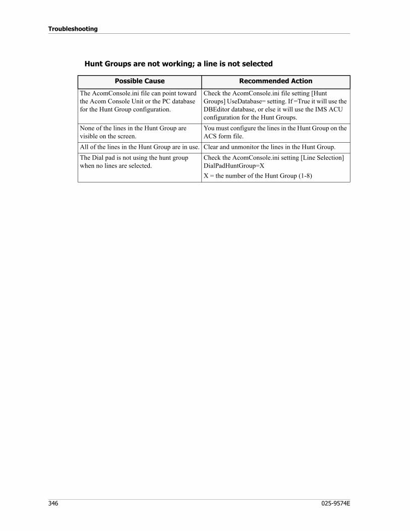
Troubleshooting
346 025-9574E
Hunt Groups are not working; a line is not selected
Possible Cause Recommended Action
The AcomConsole.ini file can point toward the Acom Console Unit or the PC database for the Hunt Group configuration.
Check the AcomConsole.ini file setting [Hunt Groups] UseDatabase= setting. If =True it will use the DBEditor database, or else it will use the IMS ACU configuration for the Hunt Groups.
None of the lines in the Hunt Group are visible on the screen.
You must configure the lines in the Hunt Group on the ACS form file.
All of the lines in the Hunt Group are in use. Clear and unmonitor the lines in the Hunt Group.The Dial pad is not using the hunt group when no lines are selected.
Check the AcomConsole.ini setting [Line Selection] DialPadHuntGroup=XX = the number of the Hunt Group (1-8)
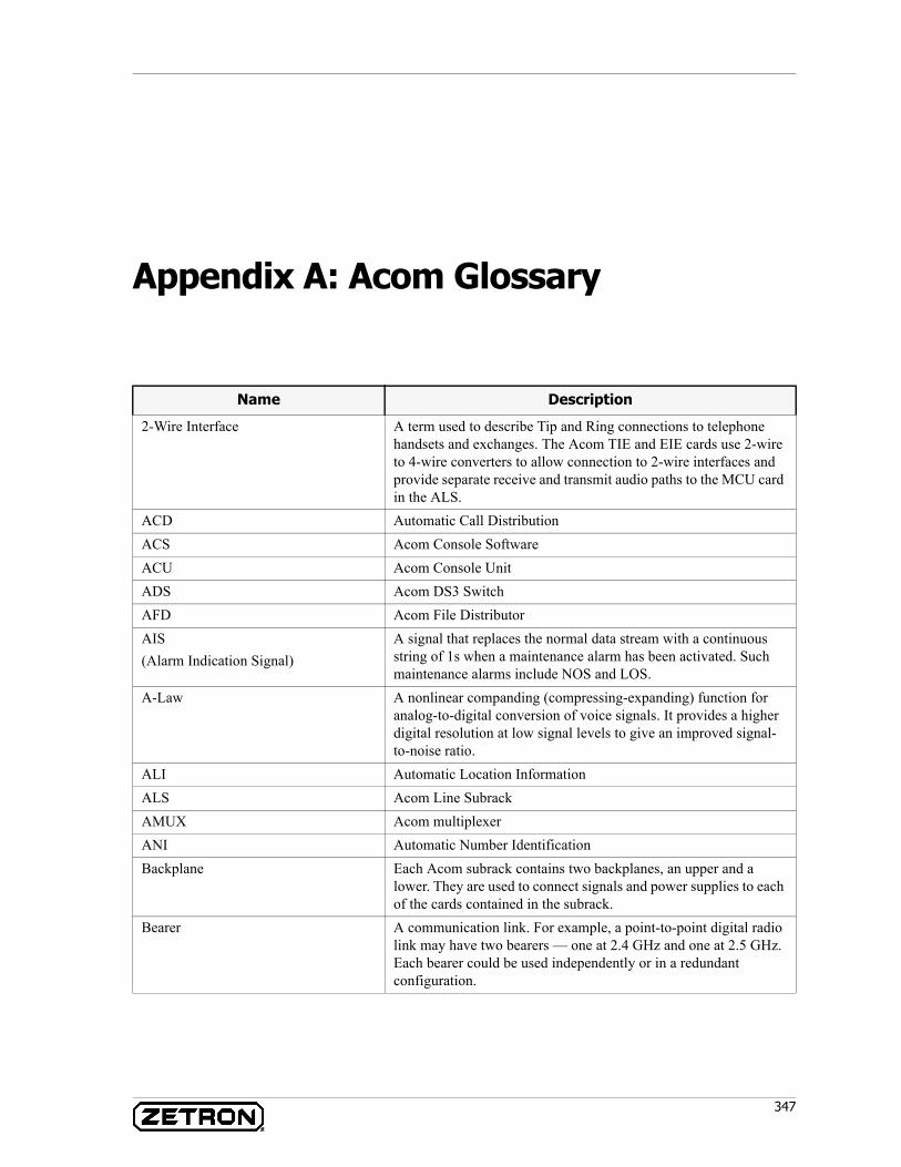
347
Appendix A: Acom Glossary
Name Description
2-Wire Interface A term used to describe Tip and Ring connections to telephone handsets and exchanges. The Acom TIE and EIE cards use 2-wire to 4-wire converters to allow connection to 2-wire interfaces and provide separate receive and transmit audio paths to the MCU card in the ALS.
ACD Automatic Call DistributionACS Acom Console SoftwareACU Acom Console UnitADS Acom DS3 SwitchAFD Acom File DistributorAIS(Alarm Indication Signal)
A signal that replaces the normal data stream with a continuous string of 1s when a maintenance alarm has been activated. Such maintenance alarms include NOS and LOS.
A-Law A nonlinear companding (compressing-expanding) function for analog-to-digital conversion of voice signals. It provides a higher digital resolution at low signal levels to give an improved signal-to-noise ratio.
ALI Automatic Location InformationALS Acom Line SubrackAMUX Acom multiplexerANI Automatic Number IdentificationBackplane Each Acom subrack contains two backplanes, an upper and a
lower. They are used to connect signals and power supplies to each of the cards contained in the subrack.
Bearer A communication link. For example, a point-to-point digital radio link may have two bearers — one at 2.4 GHz and one at 2.5 GHz. Each bearer could be used independently or in a redundant configuration.
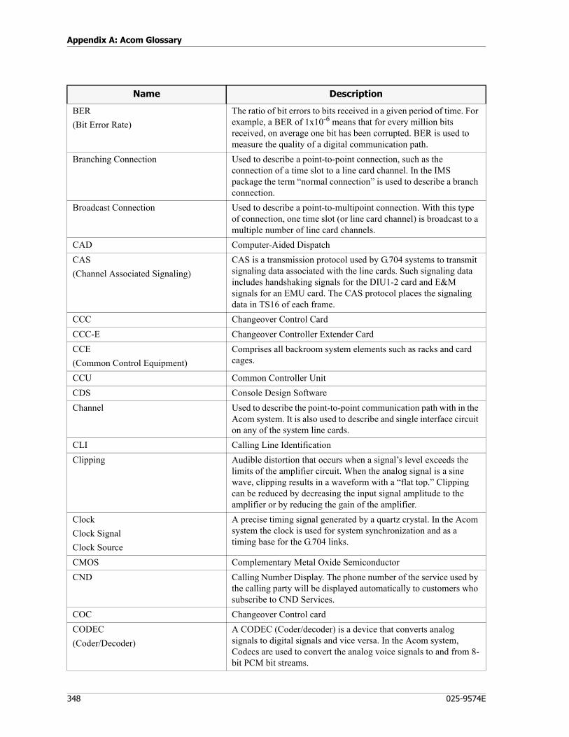
Appendix A: Acom Glossary
348 025-9574E
BER(Bit Error Rate)
The ratio of bit errors to bits received in a given period of time. For example, a BER of 1x10⁻⁶ means that for every million bits received, on average one bit has been corrupted. BER is used to measure the quality of a digital communication path.
Branching Connection Used to describe a point-to-point connection, such as the connection of a time slot to a line card channel. In the IMS package the term “normal connection” is used to describe a branch connection.
Broadcast Connection Used to describe a point-to-multipoint connection. With this type of connection, one time slot (or line card channel) is broadcast to a multiple number of line card channels.
CAD Computer-Aided DispatchCAS(Channel Associated Signaling)
CAS is a transmission protocol used by G.704 systems to transmit signaling data associated with the line cards. Such signaling data includes handshaking signals for the DIU1-2 card and E&M signals for an EMU card. The CAS protocol places the signaling data in TS16 of each frame.
CCC Changeover Control CardCCC-E Changeover Controller Extender CardCCE(Common Control Equipment)
Comprises all backroom system elements such as racks and card cages.
CCU Common Controller UnitCDS Console Design SoftwareChannel Used to describe the point-to-point communication path with in the
Acom system. It is also used to describe and single interface circuit on any of the system line cards.
CLI Calling Line IdentificationClipping Audible distortion that occurs when a signal’s level exceeds the
limits of the amplifier circuit. When the analog signal is a sine wave, clipping results in a waveform with a “flat top.” Clipping can be reduced by decreasing the input signal amplitude to the amplifier or by reducing the gain of the amplifier.
ClockClock SignalClock Source
A precise timing signal generated by a quartz crystal. In the Acom system the clock is used for system synchronization and as a timing base for the G.704 links.
CMOS Complementary Metal Oxide SemiconductorCND Calling Number Display. The phone number of the service used by
the calling party will be displayed automatically to customers who subscribe to CND Services.
COC Changeover Control cardCODEC(Coder/Decoder)
A CODEC (Coder/decoder) is a device that converts analog signals to digital signals and vice versa. In the Acom system, Codecs are used to convert the analog voice signals to and from 8-bit PCM bit streams.
Name Description
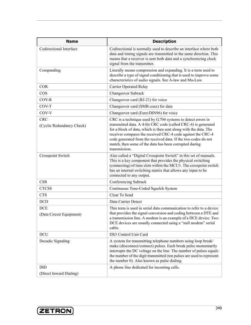
349
Codirectional Interface Codirectional is normally used to describe an interface where both data and timing signals are transmitted in the same direction. This means that a receiver is sent both data and a synchronizing clock signal from the transmitter.
Companding Literally means compression and expanding. It is a term used to describe a type of signal conditioning that is used to improve some characteristics of audio signals. See A-law and Mu-Law.
COR Carrier Operated RelayCOS Changeover SubrackCOV-R Changeover card (RJ-21) for voiceCOV-T Changeover card (SMB coax) for dataCOV-V Changeover card (Euro/DIN96) for voiceCRC(Cyclic Redundancy Check)
CRC is a technique used by G.704 systems to detect errors in transmitted data. A 4-bit CRC code (called CRC-4) is generated for a block of data, which is then sent along with the data. The receiver compares the received CRC-4 code against the CRC-4 code generated from the received data. If the two codes do not match, then some of the data has been corrupted during transmission.
Crosspoint Switch Also called a “Digital Crosspoint Switch” in this set of manuals. This is a key component that provides the physical switching (connecting) of time slots within the MCU3. The crosspoint switch has an internal switching matrix that allows any input to be connected to any output.
CSR Conferencing SubrackCTCSS Continuous Tone-Coded Squelch SystemCTS Clear To SendDCD Data Carrier DetectDCE(Data Circuit Equipment)
This term is used in serial data communication to refer to a device that provides the signal conversion and coding between a DTE and a transmission line. A modem is an example of a DCE device. Two DCE devices are usually connected using a “null modem” serial cable.
DCU DS3 Control Unit CardDecadic Signaling A system for transmitting telephone numbers using loop break/
make (disconnect/connect) pulses. Each break pulse momentarily interrupts the DC voltage on the line. The number of pulses equals the number of the digit transmitted (ten pulses are used to represent the number 0). Also known as pulse dialing.
DID(Direct Inward Dialing)
A phone line dedicated for incoming calls.
Name Description
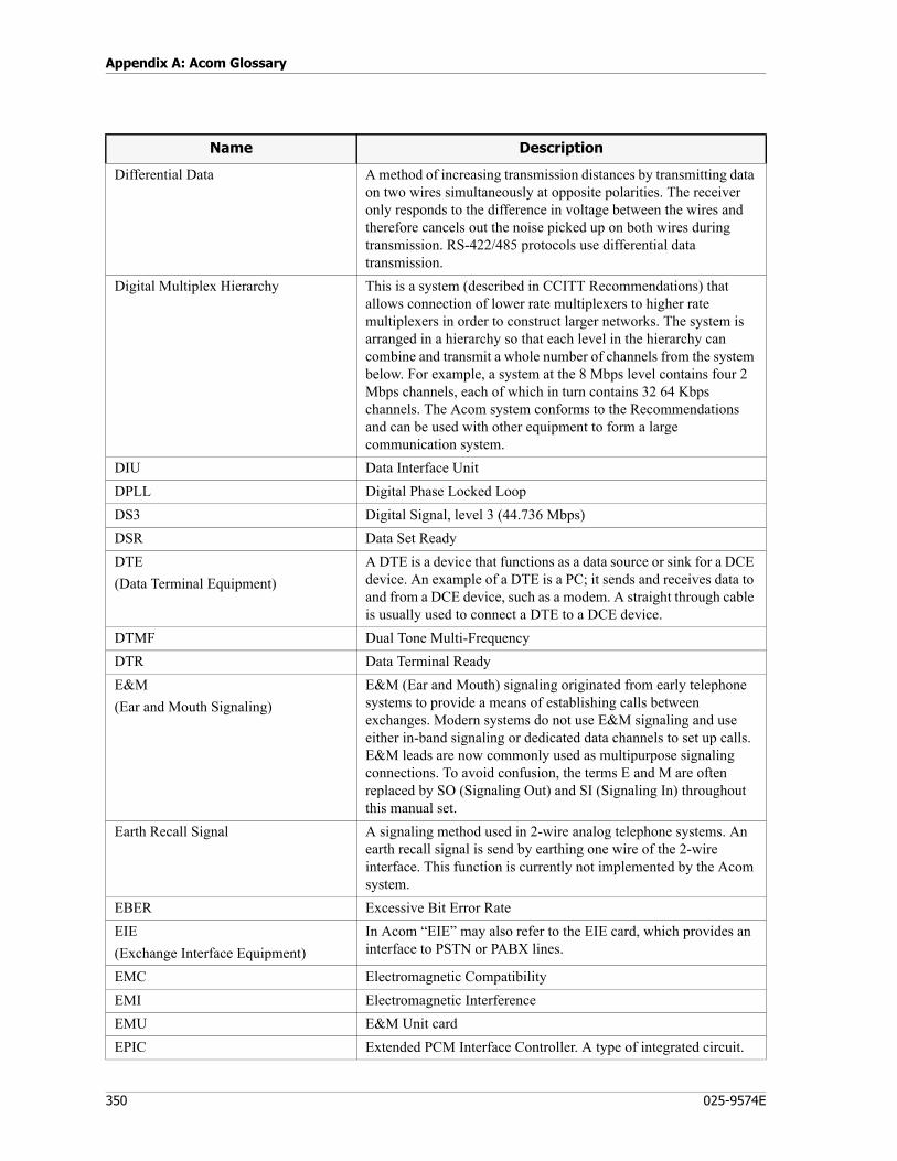
Appendix A: Acom Glossary
350 025-9574E
Differential Data A method of increasing transmission distances by transmitting data on two wires simultaneously at opposite polarities. The receiver only responds to the difference in voltage between the wires and therefore cancels out the noise picked up on both wires during transmission. RS-422/485 protocols use differential data transmission.
Digital Multiplex Hierarchy This is a system (described in CCITT Recommendations) that allows connection of lower rate multiplexers to higher rate multiplexers in order to construct larger networks. The system is arranged in a hierarchy so that each level in the hierarchy can combine and transmit a whole number of channels from the system below. For example, a system at the 8 Mbps level contains four 2 Mbps channels, each of which in turn contains 32 64 Kbps channels. The Acom system conforms to the Recommendations and can be used with other equipment to form a large communication system.
DIU Data Interface UnitDPLL Digital Phase Locked LoopDS3 Digital Signal, level 3 (44.736 Mbps)DSR Data Set ReadyDTE(Data Terminal Equipment)
A DTE is a device that functions as a data source or sink for a DCE device. An example of a DTE is a PC; it sends and receives data to and from a DCE device, such as a modem. A straight through cable is usually used to connect a DTE to a DCE device.
DTMF Dual Tone Multi-FrequencyDTR Data Terminal ReadyE&M(Ear and Mouth Signaling)
E&M (Ear and Mouth) signaling originated from early telephone systems to provide a means of establishing calls between exchanges. Modern systems do not use E&M signaling and use either in-band signaling or dedicated data channels to set up calls. E&M leads are now commonly used as multipurpose signaling connections. To avoid confusion, the terms E and M are often replaced by SO (Signaling Out) and SI (Signaling In) throughout this manual set.
Earth Recall Signal A signaling method used in 2-wire analog telephone systems. An earth recall signal is send by earthing one wire of the 2-wire interface. This function is currently not implemented by the Acom system.
EBER Excessive Bit Error RateEIE(Exchange Interface Equipment)
In Acom “EIE” may also refer to the EIE card, which provides an interface to PSTN or PABX lines.
EMC Electromagnetic CompatibilityEMI Electromagnetic InterferenceEMU E&M Unit cardEPIC Extended PCM Interface Controller. A type of integrated circuit.
Name Description
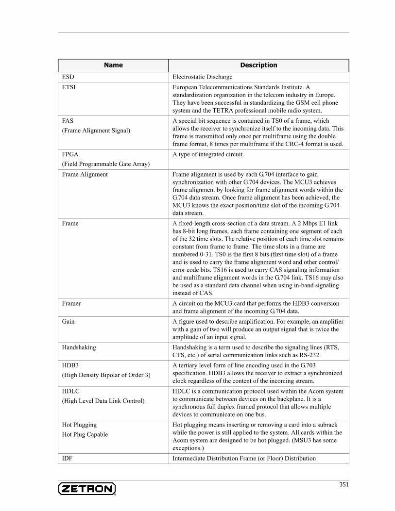
351
ESD Electrostatic DischargeETSI European Telecommunications Standards Institute. A
standardization organization in the telecom industry in Europe. They have been successful in standardizing the GSM cell phone system and the TETRA professional mobile radio system.
FAS(Frame Alignment Signal)
A special bit sequence is contained in TS0 of a frame, which allows the receiver to synchronize itself to the incoming data. This frame is transmitted only once per multiframe using the double frame format, 8 times per multiframe if the CRC-4 format is used.
FPGA (Field Programmable Gate Array)
A type of integrated circuit.
Frame Alignment Frame alignment is used by each G.704 interface to gain synchronization with other G.704 devices. The MCU3 achieves frame alignment by looking for frame alignment words within the G.704 data stream. Once frame alignment has been achieved, the MCU3 knows the exact position/time slot of the incoming G.704 data stream.
Frame A fixed-length cross-section of a data stream. A 2 Mbps E1 link has 8-bit long frames, each frame containing one segment of each of the 32 time slots. The relative position of each time slot remains constant from frame to frame. The time slots in a frame are numbered 0-31. TS0 is the first 8 bits (first time slot) of a frame and is used to carry the frame alignment word and other control/error code bits. TS16 is used to carry CAS signaling information and multiframe alignment words in the G.704 link. TS16 may also be used as a standard data channel when using in-band signaling instead of CAS.
Framer A circuit on the MCU3 card that performs the HDB3 conversion and frame alignment of the incoming G.704 data.
Gain A figure used to describe amplification. For example, an amplifier with a gain of two will produce an output signal that is twice the amplitude of an input signal.
Handshaking Handshaking is a term used to describe the signaling lines (RTS, CTS, etc.) of serial communication links such as RS-232.
HDB3(High Density Bipolar of Order 3)
A tertiary level form of line encoding used in the G.703 specification. HDB3 allows the receiver to extract a synchronized clock regardless of the content of the incoming stream.
HDLC(High Level Data Link Control)
HDLC is a communication protocol used within the Acom system to communicate between devices on the backplane. It is a synchronous full duplex framed protocol that allows multiple devices to communicate on one bus.
Hot PluggingHot Plug Capable
Hot plugging means inserting or removing a card into a subrack while the power is still applied to the system. All cards within the Acom system are designed to be hot plugged. (MSU3 has some exceptions.)
IDF Intermediate Distribution Frame (or Floor) Distribution
Name Description

Appendix A: Acom Glossary
352 025-9574E
IMS Terminal(Integrated Management System)
A top level applications package that manages access to the IMS applications for configuration, monitoring, and diagnostics for each part of every CCE and Acom Console Unit in your system. ACS may have the following modules installed: IMS ALS, IMS ADS, and IMS ACU.
IMS(Integrated Management System)
A software suite produced by Zetron for the management of Acom systems. The suite contains several IMS modules that can each run in a stand-alone environment or within ACS. IMS provides a fully functional network management system capable of configuration, remote reconfiguration, fault detection, and diagnostics through a graphical display interface. IMS allows easy configuration and maintenance for the entire system, from general component setting and network adjustments, to individual card configuration.
In-band Signaling In-band signaling is a method use to transmit signaling information. The signaling information is placed into the same time slot as the data for that channel.
IOM-2(ISDN Oriented Modular bus,version 2)
This is a communication bus used internally by the Acom system, that provides a means for communication with voice and signaling interfaces on line cards. It is a framed protocol with data sent in time slots between cards in the subrack.
IPAT(ISDN Primary Access Transceiver)
A type of integrated circuit.
IRR(Instant Recall Recorder)
IRR is an application used to control the voice recording process.
ISB(Intersite Bearer)
A means of interconnecting two or more Acom systems that are at different sites to provide remote or backup operation. ISB connections are implemented between ADSs of separate Acom sites, by way of E1 or T1 connections on the MCU4 cards.
ISDN(Integrated Services Digital Network)
A network that provides or supports a range of telecommunication services by providing digital connections between user network interfaces.
LCB Link Control BlockLine Break A term used in telephone systems to indicate a break (opening) of a
telephone line. Brief line breaks are used in decadic dialing, while an extended line break is used to release (hang up) a connection.
Line Card This is a general term that refers to the voice and data cards. A line card contains a number of channels to decode/encode local signals that can then be branched to other channels or time slots by using a G.703 link.
Link This term is used to describe a communication path that is used to transfer multiple channels of information. In the case of the Acom documentation, “link” means a connection from a 2048 or 1544 Kbps G.703 interface.
LIT Line Integrity Test card
Name Description
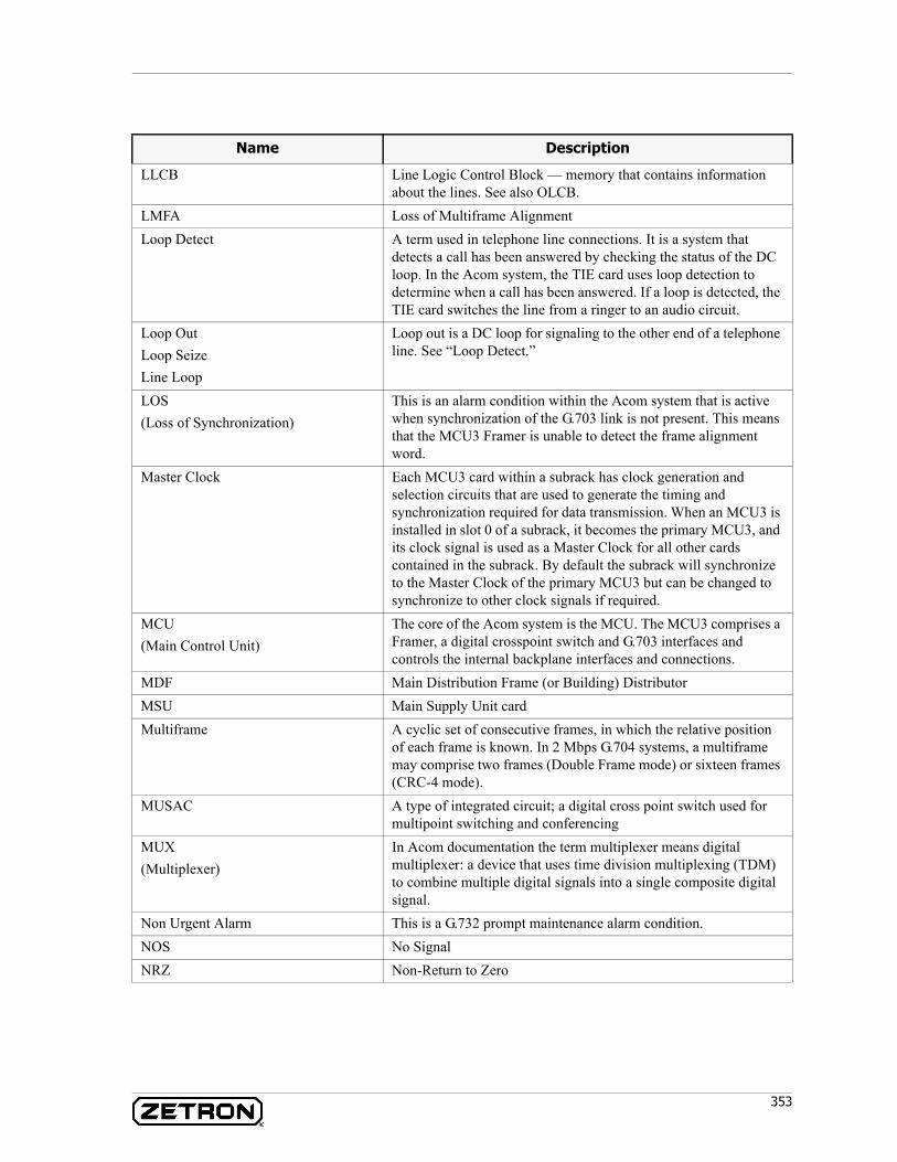
353
LLCB Line Logic Control Block — memory that contains information about the lines. See also OLCB.
LMFA Loss of Multiframe AlignmentLoop Detect A term used in telephone line connections. It is a system that
detects a call has been answered by checking the status of the DC loop. In the Acom system, the TIE card uses loop detection to determine when a call has been answered. If a loop is detected, the TIE card switches the line from a ringer to an audio circuit.
Loop OutLoop SeizeLine Loop
Loop out is a DC loop for signaling to the other end of a telephone line. See “Loop Detect.”
LOS(Loss of Synchronization)
This is an alarm condition within the Acom system that is active when synchronization of the G.703 link is not present. This means that the MCU3 Framer is unable to detect the frame alignment word.
Master Clock Each MCU3 card within a subrack has clock generation and selection circuits that are used to generate the timing and synchronization required for data transmission. When an MCU3 is installed in slot 0 of a subrack, it becomes the primary MCU3, and its clock signal is used as a Master Clock for all other cards contained in the subrack. By default the subrack will synchronize to the Master Clock of the primary MCU3 but can be changed to synchronize to other clock signals if required.
MCU(Main Control Unit)
The core of the Acom system is the MCU. The MCU3 comprises a Framer, a digital crosspoint switch and G.703 interfaces and controls the internal backplane interfaces and connections.
MDF Main Distribution Frame (or Building) DistributorMSU Main Supply Unit cardMultiframe A cyclic set of consecutive frames, in which the relative position
of each frame is known. In 2 Mbps G.704 systems, a multiframe may comprise two frames (Double Frame mode) or sixteen frames (CRC-4 mode).
MUSAC A type of integrated circuit; a digital cross point switch used for multipoint switching and conferencing
MUX(Multiplexer)
In Acom documentation the term multiplexer means digital multiplexer: a device that uses time division multiplexing (TDM) to combine multiple digital signals into a single composite digital signal.
Non Urgent Alarm This is a G.732 prompt maintenance alarm condition.NOS No SignalNRZ Non-Return to Zero
Name Description
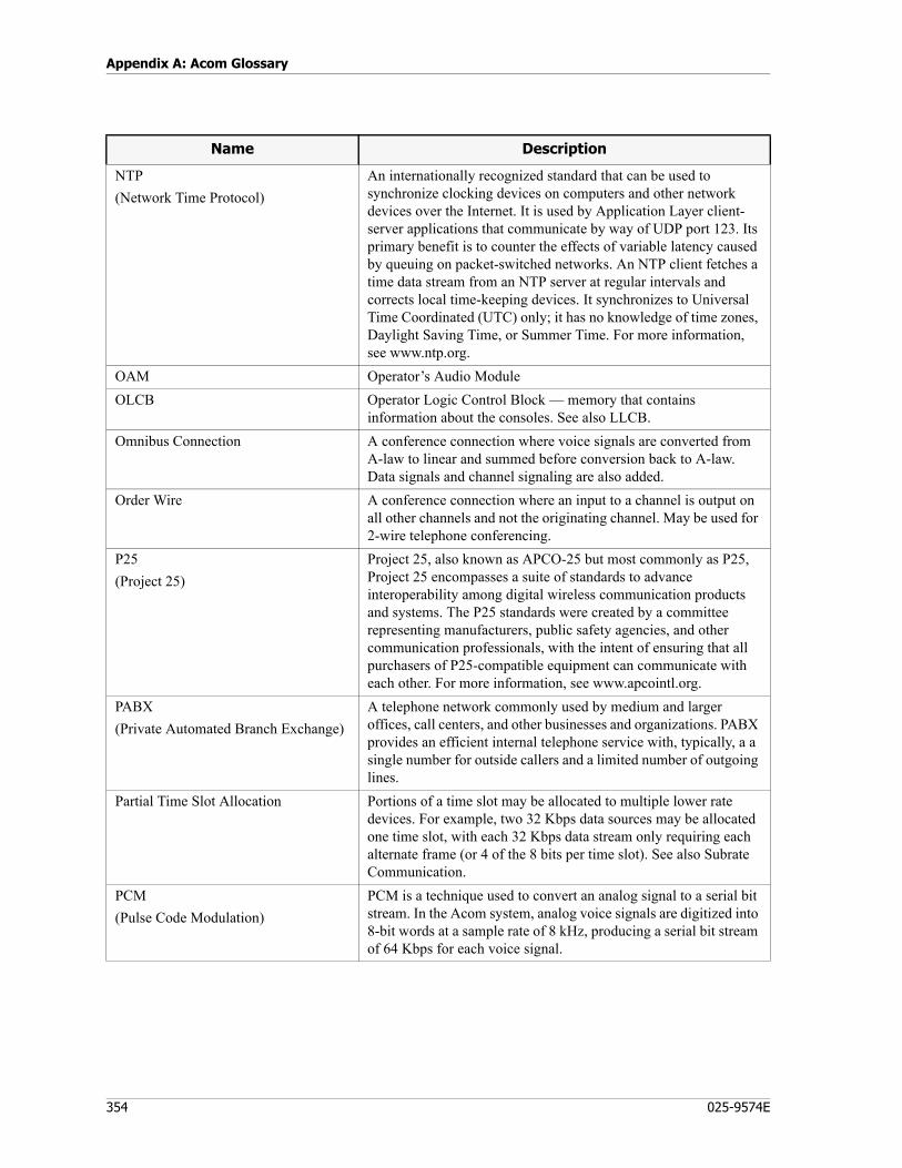
Appendix A: Acom Glossary
354 025-9574E
NTP(Network Time Protocol)
An internationally recognized standard that can be used to synchronize clocking devices on computers and other network devices over the Internet. It is used by Application Layer client-server applications that communicate by way of UDP port 123. Its primary benefit is to counter the effects of variable latency caused by queuing on packet-switched networks. An NTP client fetches a time data stream from an NTP server at regular intervals and corrects local time-keeping devices. It synchronizes to Universal Time Coordinated (UTC) only; it has no knowledge of time zones, Daylight Saving Time, or Summer Time. For more information, see www.ntp.org.
OAM Operator’s Audio ModuleOLCB Operator Logic Control Block — memory that contains
information about the consoles. See also LLCB.Omnibus Connection A conference connection where voice signals are converted from
A-law to linear and summed before conversion back to A-law. Data signals and channel signaling are also added.
Order Wire A conference connection where an input to a channel is output on all other channels and not the originating channel. May be used for 2-wire telephone conferencing.
P25(Project 25)
Project 25, also known as APCO-25 but most commonly as P25, Project 25 encompasses a suite of standards to advance interoperability among digital wireless communication products and systems. The P25 standards were created by a committee representing manufacturers, public safety agencies, and other communication professionals, with the intent of ensuring that all purchasers of P25-compatible equipment can communicate with each other. For more information, see www.apcointl.org.
PABX(Private Automated Branch Exchange)
A telephone network commonly used by medium and larger offices, call centers, and other businesses and organizations. PABX provides an efficient internal telephone service with, typically, a a single number for outside callers and a limited number of outgoing lines.
Partial Time Slot Allocation Portions of a time slot may be allocated to multiple lower rate devices. For example, two 32 Kbps data sources may be allocated one time slot, with each 32 Kbps data stream only requiring each alternate frame (or 4 of the 8 bits per time slot). See also Subrate Communication.
PCM(Pulse Code Modulation)
PCM is a technique used to convert an analog signal to a serial bit stream. In the Acom system, analog voice signals are digitized into 8-bit words at a sample rate of 8 kHz, producing a serial bit stream of 64 Kbps for each voice signal.
Name Description
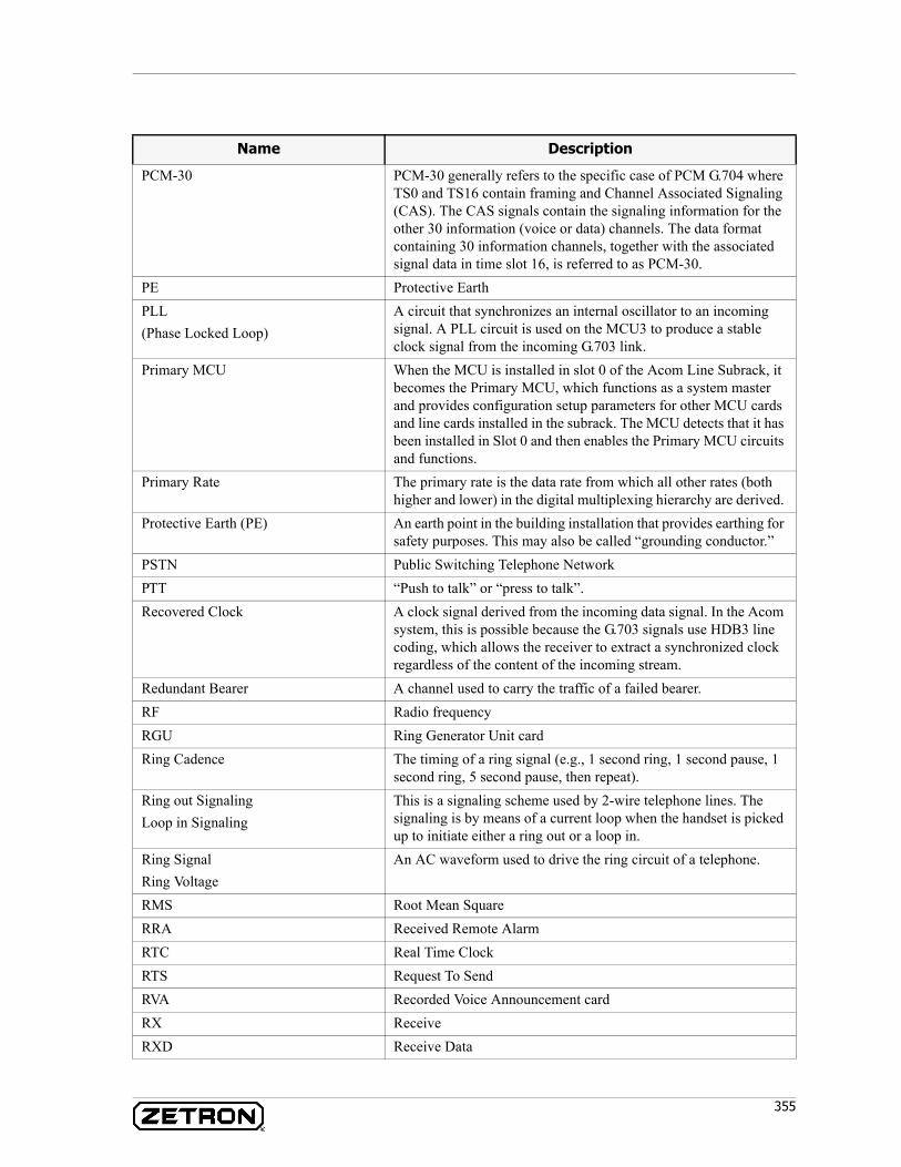
355
PCM-30 PCM-30 generally refers to the specific case of PCM G.704 where TS0 and TS16 contain framing and Channel Associated Signaling (CAS). The CAS signals contain the signaling information for the other 30 information (voice or data) channels. The data format containing 30 information channels, together with the associated signal data in time slot 16, is referred to as PCM-30.
PE Protective EarthPLL(Phase Locked Loop)
A circuit that synchronizes an internal oscillator to an incoming signal. A PLL circuit is used on the MCU3 to produce a stable clock signal from the incoming G.703 link.
Primary MCU When the MCU is installed in slot 0 of the Acom Line Subrack, it becomes the Primary MCU, which functions as a system master and provides configuration setup parameters for other MCU cards and line cards installed in the subrack. The MCU detects that it has been installed in Slot 0 and then enables the Primary MCU circuits and functions.
Primary Rate The primary rate is the data rate from which all other rates (both higher and lower) in the digital multiplexing hierarchy are derived.
Protective Earth (PE) An earth point in the building installation that provides earthing for safety purposes. This may also be called “grounding conductor.”
PSTN Public Switching Telephone NetworkPTT “Push to talk” or “press to talk”.Recovered Clock A clock signal derived from the incoming data signal. In the Acom
system, this is possible because the G.703 signals use HDB3 line coding, which allows the receiver to extract a synchronized clock regardless of the content of the incoming stream.
Redundant Bearer A channel used to carry the traffic of a failed bearer.RF Radio frequencyRGU Ring Generator Unit cardRing Cadence The timing of a ring signal (e.g., 1 second ring, 1 second pause, 1
second ring, 5 second pause, then repeat).Ring out SignalingLoop in Signaling
This is a signaling scheme used by 2-wire telephone lines. The signaling is by means of a current loop when the handset is picked up to initiate either a ring out or a loop in.
Ring SignalRing Voltage
An AC waveform used to drive the ring circuit of a telephone.
RMS Root Mean SquareRRA Received Remote AlarmRTC Real Time ClockRTS Request To SendRVA Recorded Voice Announcement cardRX ReceiveRXD Receive Data
Name Description
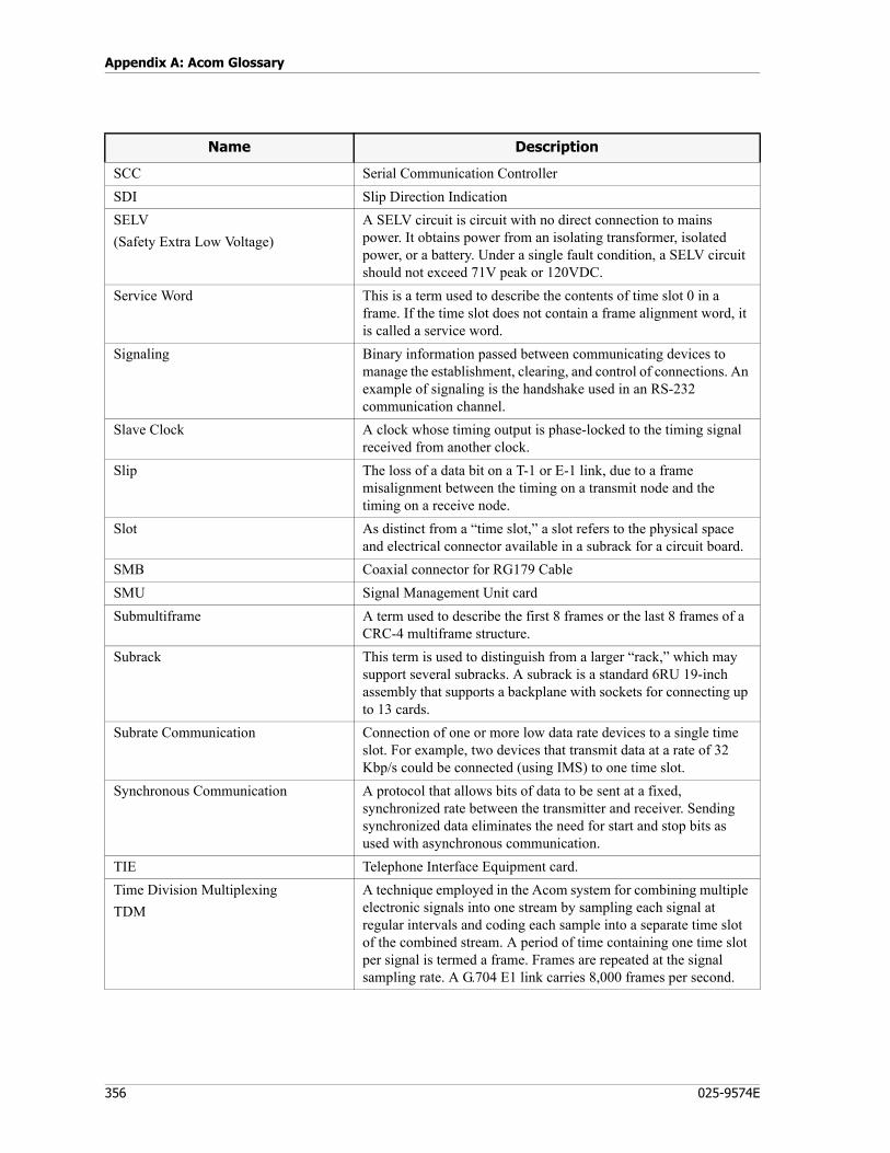
Appendix A: Acom Glossary
356 025-9574E
SCC Serial Communication ControllerSDI Slip Direction IndicationSELV(Safety Extra Low Voltage)
A SELV circuit is circuit with no direct connection to mains power. It obtains power from an isolating transformer, isolated power, or a battery. Under a single fault condition, a SELV circuit should not exceed 71V peak or 120VDC.
Service Word This is a term used to describe the contents of time slot 0 in a frame. If the time slot does not contain a frame alignment word, it is called a service word.
Signaling Binary information passed between communicating devices to manage the establishment, clearing, and control of connections. An example of signaling is the handshake used in an RS-232 communication channel.
Slave Clock A clock whose timing output is phase-locked to the timing signal received from another clock.
Slip The loss of a data bit on a T-1 or E-1 link, due to a frame misalignment between the timing on a transmit node and the timing on a receive node.
Slot As distinct from a “time slot,” a slot refers to the physical space and electrical connector available in a subrack for a circuit board.
SMB Coaxial connector for RG179 CableSMU Signal Management Unit cardSubmultiframe A term used to describe the first 8 frames or the last 8 frames of a
CRC-4 multiframe structure. Subrack This term is used to distinguish from a larger “rack,” which may
support several subracks. A subrack is a standard 6RU 19-inch assembly that supports a backplane with sockets for connecting up to 13 cards.
Subrate Communication Connection of one or more low data rate devices to a single time slot. For example, two devices that transmit data at a rate of 32 Kbp/s could be connected (using IMS) to one time slot.
Synchronous Communication A protocol that allows bits of data to be sent at a fixed, synchronized rate between the transmitter and receiver. Sending synchronized data eliminates the need for start and stop bits as used with asynchronous communication.
TIE Telephone Interface Equipment card.Time Division MultiplexingTDM
A technique employed in the Acom system for combining multiple electronic signals into one stream by sampling each signal at regular intervals and coding each sample into a separate time slot of the combined stream. A period of time containing one time slot per signal is termed a frame. Frames are repeated at the signal sampling rate. A G.704 E1 link carries 8,000 frames per second.
Name Description

357
Time SlotTS
In the context of TDM, the data stream is divided into parallel time slots. An E1 link carries 32 time slots, each representing one 64 Kbps channel. Each time slot is divided into serial frames, each 8 bits long.
TNV(Telecommunication Network Voltage)
A circuit that under normal operating conditions carries telecommunication signals. Telecommunication signals are a steady state, varying amplitude, or intermittent voltage or current intended for use on a telecommunication network. A TNV circuit, which is connected to a telecommunication network, may be subject to over-voltages due to lightning or power system faults. TNV excludes the mains supply, TV cable systems and SELV circuits.
Traffic General reference to data signals, that are intended for multiplexing and demultiplexing within an Acom system. Intended to distinguish from and exclude signals, that are used internally to the system, such as for system coordination and CPU operations.
Transceiver A circuit that can connect to a shared bus for the purpose of receiving and transmitting. A cooperative protocol for the bus ensures that only one transceiver on a bus transmits at any one time.
TRC Telecom Reference ConductorTS Time SlotTSI Time Slot InterchangeTTL Transistor-Transistor LogicTX TransmitTXD Transmit DataUIO Universal Input/Output cardUMS(User Management System)
UMS is a client/server application used to control system access and privileges.
Urgent Alarm This is a G.732 service alarm condition.VF (Voice Frequency) An audio signal in the band 300-3400 Hz.VoIP (Voice over Internet Protocol) A method for using IP-compatible networks such as a LAN or
WAN to convey voice communication or other audio such as radio control tones.
Watchdog Timer A watchdog timer is a circuit that monitors a microprocessor. If the microprocessor stops responding, the watchdog timer will reset the microprocessor in an attempt to resume normal operation.
Name Description

Appendix A: Acom Glossary
358 025-9574E
Purpose
359
Appendix B: System Failure Worksheet
Purpose
To provide a worksheet to be filled out in case of an Acom system with a severe failure such as an inactive or unstable system. Capturing the state of the LEDs captures information required to help determine the cause of failure. Fill out each section applicable to the failure, and report your findings to Zetron. See http://www.zetron.com for contact information.
Worksheets are available for:• DCU LEDs on page 360• MCU3/4 LEDs (in ALS) on page 362• MCU4 LEDs (in ADS) on page 364• MSU LEDs on page 366• Acom Console Unit (ACU) LEDs on page 368
Note Make as many copies of these worksheet pages as needed to capture the LED information from all ACUs, DCUs, MSUs, and MCUs in the system.
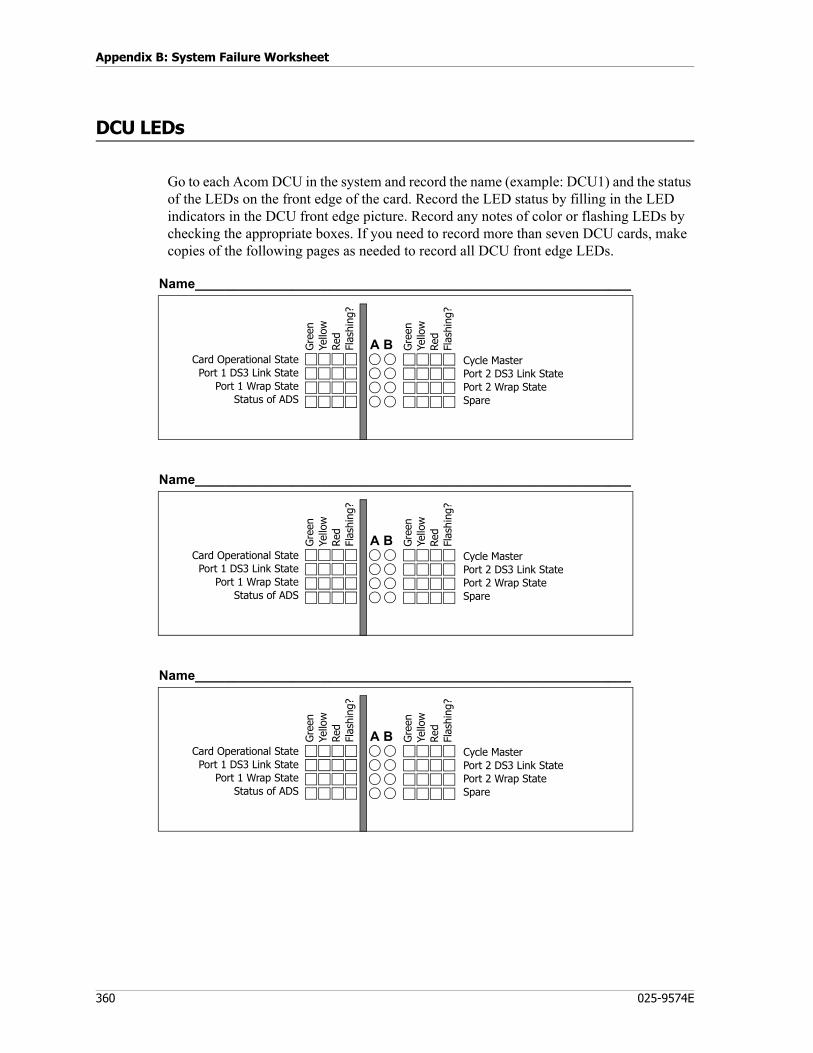
Appendix B: System Failure Worksheet
360 025-9574E
DCU LEDs
Go to each Acom DCU in the system and record the name (example: DCU1) and the status of the LEDs on the front edge of the card. Record the LED status by filling in the LED indicators in the DCU front edge picture. Record any notes of color or flashing LEDs by checking the appropriate boxes. If you need to record more than seven DCU cards, make copies of the following pages as needed to record all DCU front edge LEDs.
Cycle MasterPort 2 DS3 Link StatePort 2 Wrap StateSpare
Name___________________________________________________________
A BCard Operational StatePort 1 DS3 Link State
Port 1 Wrap StateStatus of ADS
Gre
enYe
llow
Red
Flas
hing
?
Gre
enYe
llow
Red
Flas
hing
?
Cycle MasterPort 2 DS3 Link StatePort 2 Wrap StateSpare
Name___________________________________________________________
A BCard Operational StatePort 1 DS3 Link State
Port 1 Wrap StateStatus of ADS
Gre
enYe
llow
Red
Flas
hing
?
Gre
enYe
llow
Red
Flas
hing
?
Cycle MasterPort 2 DS3 Link StatePort 2 Wrap StateSpare
Name___________________________________________________________
A BCard Operational StatePort 1 DS3 Link State
Port 1 Wrap StateStatus of ADS
Gre
enYe
llow
Red
Flas
hing
?
Gre
enYe
llow
Red
Flas
hing
?
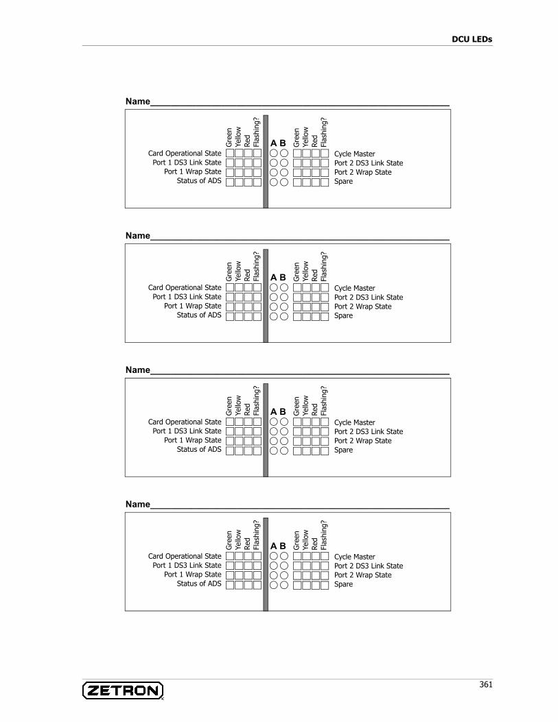
361
DCU LEDs
Cycle MasterPort 2 DS3 Link StatePort 2 Wrap StateSpare
Name___________________________________________________________
A BCard Operational StatePort 1 DS3 Link State
Port 1 Wrap StateStatus of ADS
Gre
enYe
llow
Red
Flas
hing
?
Gre
enYe
llow
Red
Flas
hing
?
Cycle MasterPort 2 DS3 Link StatePort 2 Wrap StateSpare
Name___________________________________________________________
A BCard Operational StatePort 1 DS3 Link State
Port 1 Wrap StateStatus of ADS
Gre
enYe
llow
Red
Flas
hing
?
Gre
enYe
llow
Red
Flas
hing
?
Cycle MasterPort 2 DS3 Link StatePort 2 Wrap StateSpare
Name___________________________________________________________
A BCard Operational StatePort 1 DS3 Link State
Port 1 Wrap StateStatus of ADS
Gre
enYe
llow
Red
Flas
hing
?
Gre
enYe
llow
Red
Flas
hing
?
Cycle MasterPort 2 DS3 Link StatePort 2 Wrap StateSpare
Name___________________________________________________________
A BCard Operational StatePort 1 DS3 Link State
Port 1 Wrap StateStatus of ADS
Gre
enYe
llow
Red
Flas
hing
?
Gre
enYe
llow
Red
Flas
hing
?
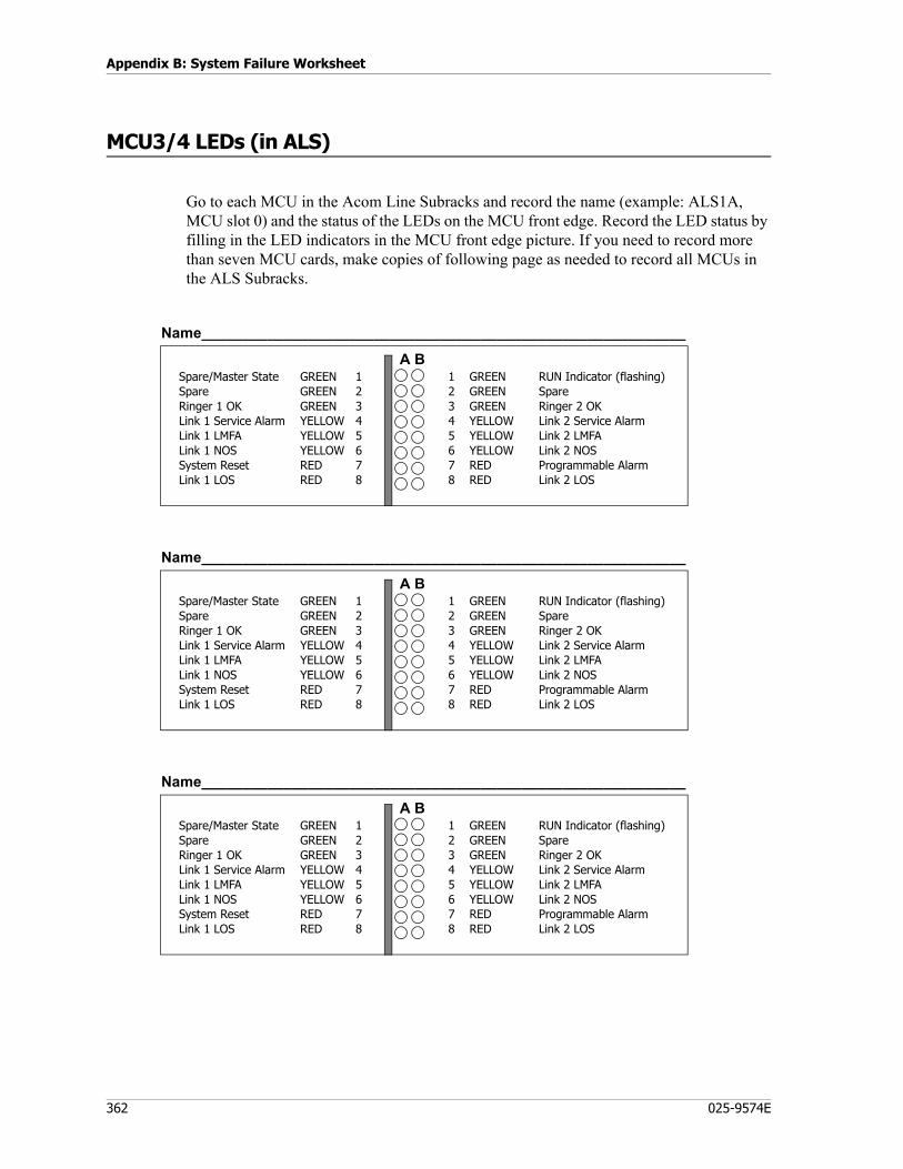
Appendix B: System Failure Worksheet
362 025-9574E
MCU3/4 LEDs (in ALS)
Go to each MCU in the Acom Line Subracks and record the name (example: ALS1A, MCU slot 0) and the status of the LEDs on the MCU front edge. Record the LED status by filling in the LED indicators in the MCU front edge picture. If you need to record more than seven MCU cards, make copies of following page as needed to record all MCUs in the ALS Subracks.
Spare/Master StateSpareRinger 1 OKLink 1 Service AlarmLink 1 LMFALink 1 NOSSystem ResetLink 1 LOS
GREEN 1GREEN 2GREEN 3YELLOW 4YELLOW 5YELLOW 6RED 7RED 8
1 GREEN2 GREEN3 GREEN4 YELLOW5 YELLOW6 YELLOW7 RED8 RED
RUN Indicator (flashing)SpareRinger 2 OKLink 2 Service AlarmLink 2 LMFALink 2 NOSProgrammable AlarmLink 2 LOS
Name___________________________________________________________
A B
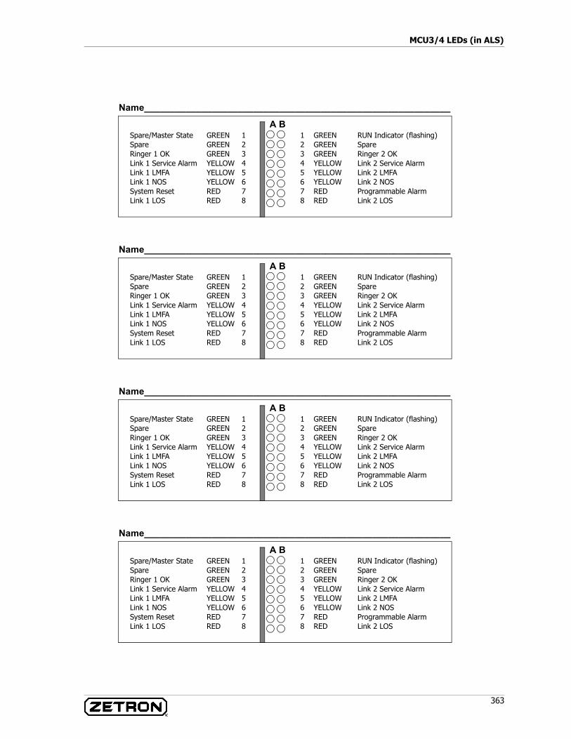
363
MCU3/4 LEDs (in ALS)
Spare/Master StateSpareRinger 1 OKLink 1 Service AlarmLink 1 LMFALink 1 NOSSystem ResetLink 1 LOS
GREEN 1GREEN 2GREEN 3YELLOW 4YELLOW 5YELLOW 6RED 7RED 8
1 GREEN2 GREEN3 GREEN4 YELLOW5 YELLOW6 YELLOW7 RED8 RED
RUN Indicator (flashing)SpareRinger 2 OKLink 2 Service AlarmLink 2 LMFALink 2 NOSProgrammable AlarmLink 2 LOS
Name___________________________________________________________
A B
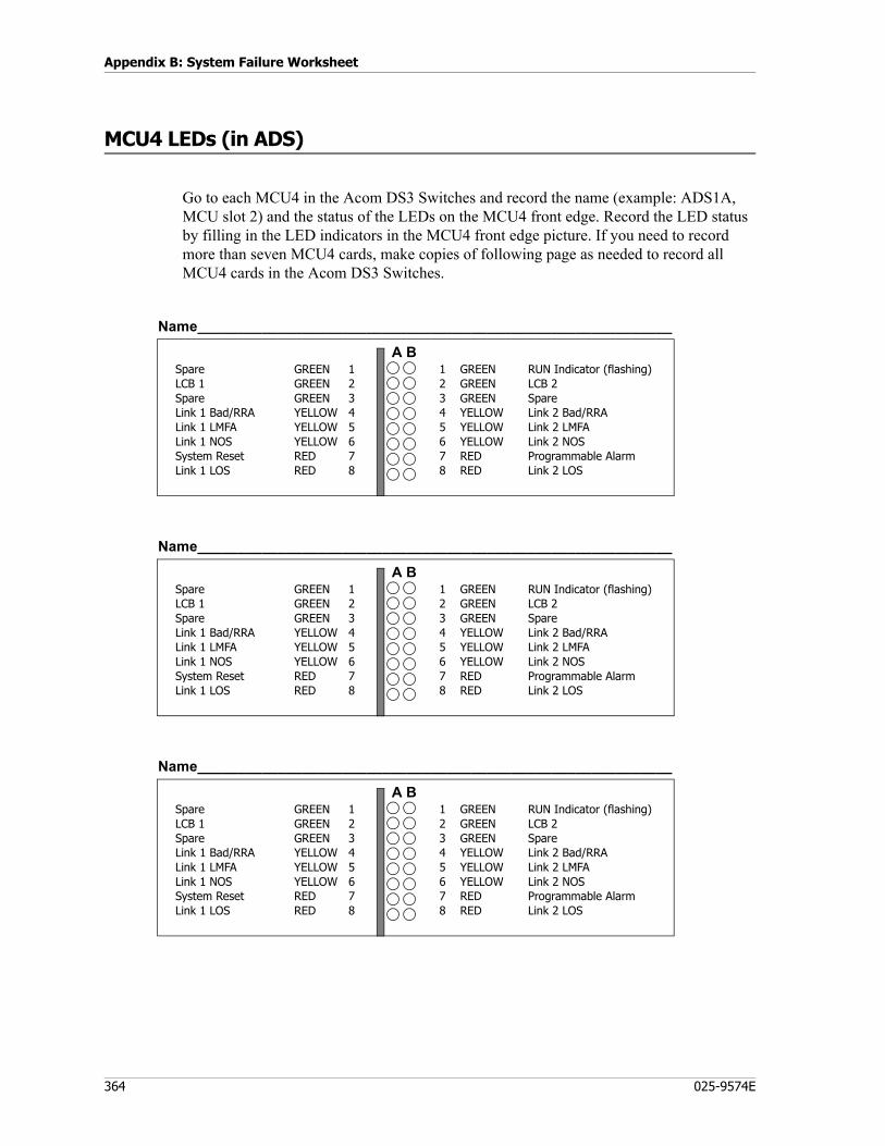
Appendix B: System Failure Worksheet
364 025-9574E
MCU4 LEDs (in ADS)
Go to each MCU4 in the Acom DS3 Switches and record the name (example: ADS1A, MCU slot 2) and the status of the LEDs on the MCU4 front edge. Record the LED status by filling in the LED indicators in the MCU4 front edge picture. If you need to record more than seven MCU4 cards, make copies of following page as needed to record all MCU4 cards in the Acom DS3 Switches.
SpareLCB 1SpareLink 1 Bad/RRALink 1 LMFALink 1 NOSSystem ResetLink 1 LOS
GREEN 1GREEN 2GREEN 3YELLOW 4YELLOW 5YELLOW 6RED 7RED 8
1 GREEN2 GREEN3 GREEN4 YELLOW5 YELLOW6 YELLOW7 RED8 RED
RUN Indicator (flashing)LCB 2SpareLink 2 Bad/RRALink 2 LMFALink 2 NOSProgrammable AlarmLink 2 LOS
Name___________________________________________________________
A B
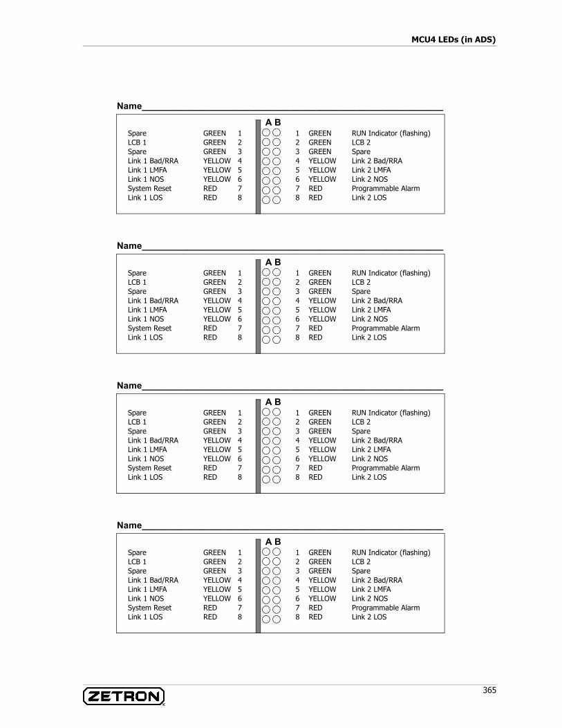
365
MCU4 LEDs (in ADS)
SpareLCB 1SpareLink 1 Bad/RRALink 1 LMFALink 1 NOSSystem ResetLink 1 LOS
GREEN 1GREEN 2GREEN 3YELLOW 4YELLOW 5YELLOW 6RED 7RED 8
1 GREEN2 GREEN3 GREEN4 YELLOW5 YELLOW6 YELLOW7 RED8 RED
RUN Indicator (flashing)LCB 2SpareLink 2 Bad/RRALink 2 LMFALink 2 NOSProgrammable AlarmLink 2 LOS
Name___________________________________________________________
A B
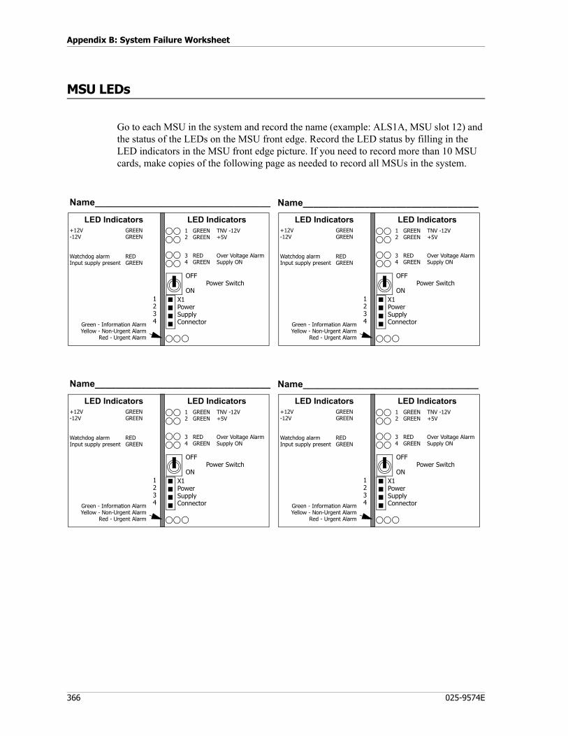
Appendix B: System Failure Worksheet
366 025-9574E
MSU LEDs
Go to each MSU in the system and record the name (example: ALS1A, MSU slot 12) and the status of the LEDs on the MSU front edge. Record the LED status by filling in the LED indicators in the MSU front edge picture. If you need to record more than 10 MSU cards, make copies of the following page as needed to record all MSUs in the system.
Name__________________________________
X1PowerSupplyConnector
3 RED Over Voltage Alarm4 GREEN Supply ON
+12V GREEN-12V GREEN
Watchdog alarm REDInput supply present GREEN
LED Indicators LED Indicators
1234Green - Information Alarm
Yellow - Non-Urgent AlarmRed - Urgent Alarm
OFFPower Switch
ON
1 GREEN TNV -12V2 GREEN +5V
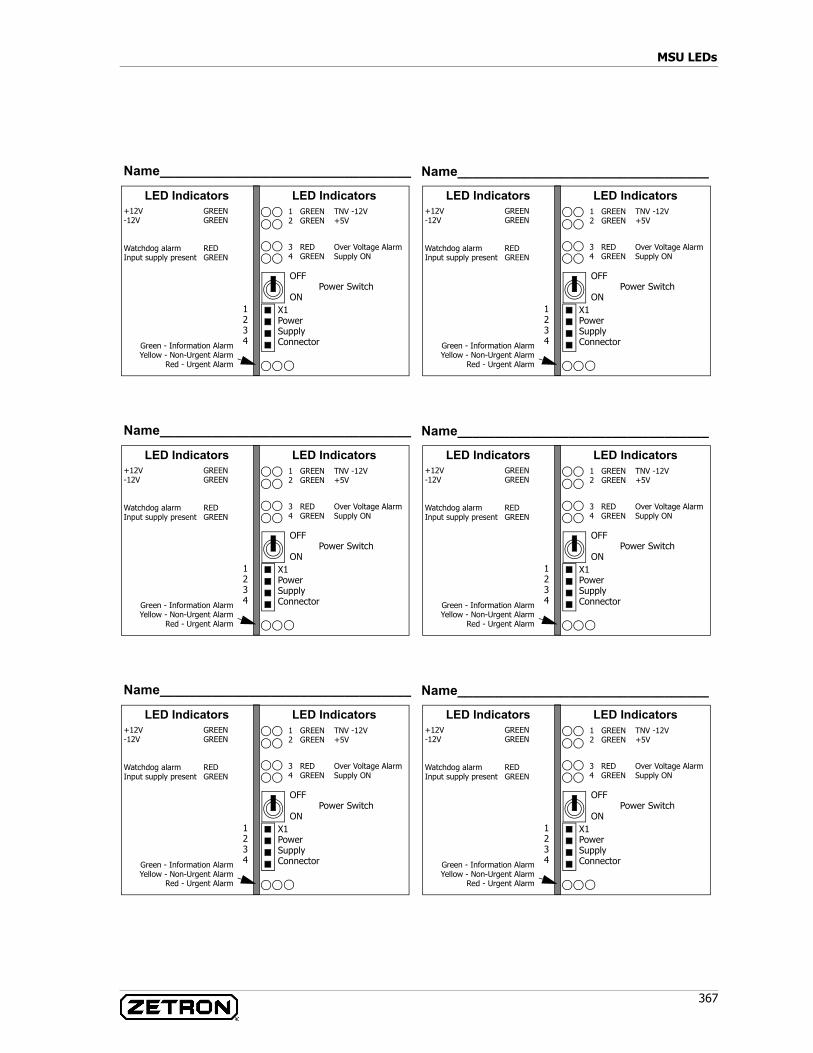
367
MSU LEDs
Name__________________________________
X1PowerSupplyConnector
3 RED Over Voltage Alarm4 GREEN Supply ON
+12V GREEN-12V GREEN
Watchdog alarm REDInput supply present GREEN
LED Indicators LED Indicators
1234Green - Information Alarm
Yellow - Non-Urgent AlarmRed - Urgent Alarm
OFFPower Switch
ON
1 GREEN TNV -12V2 GREEN +5V
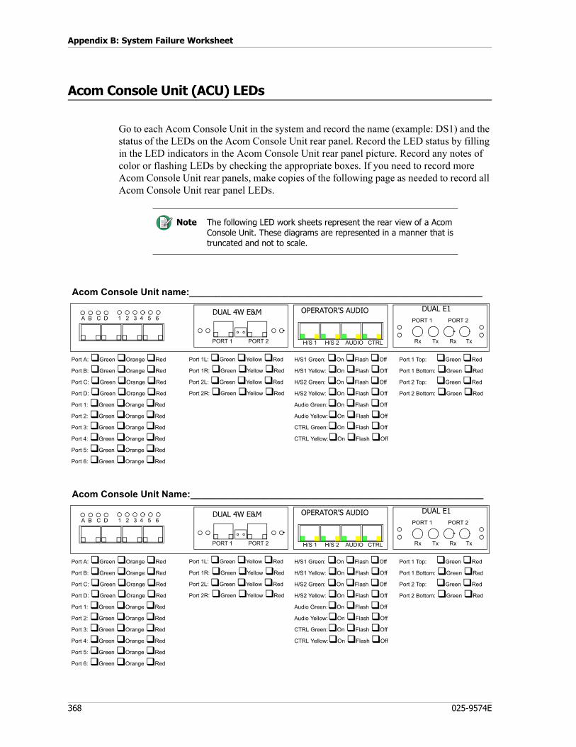
Appendix B: System Failure Worksheet
368 025-9574E
Acom Console Unit (ACU) LEDs
Go to each Acom Console Unit in the system and record the name (example: DS1) and the status of the LEDs on the Acom Console Unit rear panel. Record the LED status by filling in the LED indicators in the Acom Console Unit rear panel picture. Record any notes of color or flashing LEDs by checking the appropriate boxes. If you need to record more Acom Console Unit rear panels, make copies of the following page as needed to record all Acom Console Unit rear panel LEDs.
Note The following LED work sheets represent the rear view of a Acom Console Unit. These diagrams are represented in a manner that is truncated and not to scale.
A B C D 1 2 3 4 5 6 PORT 1 PORT 2DUAL 4W E&M OPERATOR’S AUDIO
Port A: Green Orange Red
Port B: Green Orange Red
Port C: Green Orange Red
Port D: Green Orange Red
Port 1: Green Orange Red
Port 2: Green Orange Red
Port 3: Green Orange Red
Port 4: Green Orange Red
Port 5: Green Orange Red
Port 6: Green Orange Red
Port 1L: Green Yellow Red
Port 1R: Green Yellow Red
Port 2L: Green Yellow Red
Port 2R: Green Yellow Red
H/S1 Green: On Flash Off
H/S1 Yellow: On Flash Off
H/S2 Green: On Flash Off
H/S2 Yellow: On Flash Off
Audio Green: On Flash Off
Audio Yellow: On Flash Off
CTRL Green: On Flash Off
CTRL Yellow: On Flash Off
H/S 1 H/S 2 AUDIO CTRL
Port 1 Top: Green Red
Port 1 Bottom: Green Red
Port 2 Top: Green Red
Port 2 Bottom: Green Red
DUAL E1
Rx Tx Rx Tx
Acom Console Unit name:________________________________________________________
PORT 1 PORT 2
A B C D 1 2 3 4 5 6 PORT 1 PORT 2DUAL 4W E&M OPERATOR’S AUDIO
Port A: Green Orange Red
Port B: Green Orange Red
Port C: Green Orange Red
Port D: Green Orange Red
Port 1: Green Orange Red
Port 2: Green Orange Red
Port 3: Green Orange Red
Port 4: Green Orange Red
Port 5: Green Orange Red
Port 6: Green Orange Red
Port 1L: Green Yellow Red
Port 1R: Green Yellow Red
Port 2L: Green Yellow Red
Port 2R: Green Yellow Red
H/S1 Green: On Flash Off
H/S1 Yellow: On Flash Off
H/S2 Green: On Flash Off
H/S2 Yellow: On Flash Off
Audio Green: On Flash Off
Audio Yellow: On Flash Off
CTRL Green: On Flash Off
CTRL Yellow: On Flash Off
H/S 1 H/S 2 AUDIO CTRL
Port 1 Top: Green Red
Port 1 Bottom: Green Red
Port 2 Top: Green Red
Port 2 Bottom: Green Red
DUAL E1
Rx Tx Rx Tx
Acom Console Unit Name:________________________________________________________
PORT 1 PORT 2
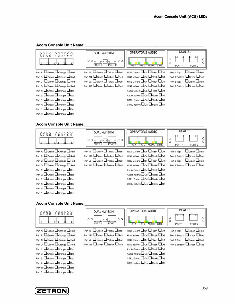
369
Acom Console Unit (ACU) LEDs
A B C D 1 2 3 4 5 6
PORT 1 PORT 2
DUAL 4W E&M OPERATOR’S AUDIO
Port A: Green Orange Red
Port B: Green Orange Red
Port C: Green Orange Red
Port D: Green Orange Red
Port 1: Green Orange Red
Port 2: Green Orange Red
Port 3: Green Orange Red
Port 4: Green Orange Red
Port 5: Green Orange Red
Port 6: Green Orange Red
Port 1L: Green Yellow Red
Port 1R: Green Yellow Red
Port 2L: Green Yellow Red
Port 2R: Green Yellow Red
H/S1 Green: On Flash Off
H/S1 Yellow: On Flash Off
H/S2 Green: On Flash Off
H/S2 Yellow: On Flash Off
Audio Green: On Flash Off
Audio Yellow: On Flash Off
CTRL Green: On Flash Off
CTRL Yellow: On Flash Off
H/S 1 H/S 2 AUDIO CTRL
Port 1 Top: Green Red
Port 1 Bottom: Green Red
Port 2 Top: Green Red
Port 2 Bottom: Green Red
DUAL E1
Acom Console Unit Name:________________________________________________________
PORT 1 PORT 2

Appendix B: System Failure Worksheet
370 025-9574E
Alarm System
371
Appendix C: Alarms
Major topics in this chapter are:Alarm System on page 371IMS Fault Logs on page 373
Fault Log Input Alarms on page 377Fault Log Output Alarms on page 382
General Alarms on page 383ALS Alarm Definitions on page 385Acom Console Unit (ACU) Alarm Definitions on page 402ADS Alarm Descriptions on page 408Supervisor Alarms in IMS on page 426Acom Console Unit (ACU) Alarms in IMS on page 428
Alarm System
Aside from the visual alarms that can be defined and monitored, there are relay contacts on the MSU card. The contacts may be connected to a wide range of external circuits and equipment; they may be configured to activate when a user defined alarm occurs. They can be deactivated in many ways, depending on the alarm mode (see Output Alarms on page 372).
Typical applications may include connection of the urgent alarm relay to a visual or audible alarm, alerting personnel of a link failure.
Note Many of the alarms identified in this chapter are listed as “not used with Acom.” These alarms, although not used with Acom hardware, appear in the IMS software because other hardware system use the alarms. All alarms are included here for completeness.
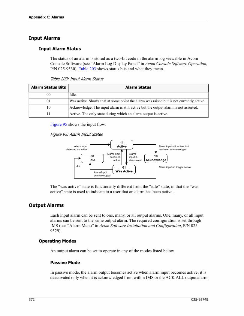
Appendix C: Alarms
372 025-9574E
Input Alarms
Input Alarm Status
The status of an alarm is stored as a two-bit code in the alarm log viewable in Acom Console Software (see “Alarm Log Display Panel” in Acom Console Software Operation, P/N 025-9530). Table 203 shows status bits and what they mean.
Table 203: Input Alarm Status
Figure 95 shows the input flow.
Figure 95: Alarm Input States
The “was active” state is functionally different from the “idle” state, in that the “was active” state is used to indicate to a user that an alarm has been active.
Output Alarms
Each input alarm can be sent to one, many, or all output alarms. One, many, or all input alarms can be sent to the same output alarm. The required configuration is set through IMS (see “Alarm Menu” in Acom Software Installation and Configuration, P/N 025-9529).
Operating Modes
An output alarm can be set to operate in any of the modes listed below.
Passive Mode
In passive mode, the alarm output becomes active when alarm input becomes active; it is deactivated only when it is acknowledged from within IMS or the ACK ALL output alarm
Alarm Status Bits Alarm Status
00 Idle.01 Was active. Shows that at some point the alarm was raised but is not currently active.10 Acknowledge. The input alarm is still active but the output alarm is not asserted.11 Active. The only state during which an alarm output is active.
11Active
01Was Active
10Acknowledge
00Idle
Alarm inputdetected as active
Alarm input still active, buthas been acknowledged
Alarm input no longer active
Alarm inputacknowledged
Idle
Alarm inputbecomes
active
Alarminput isdeactivated

373
IMS Fault Logs
or the input alarms become deactivated. Passive mode is the default operating mode for alarm outputs.
Locked Mode
In locked mode, the alarm output becomes active when the alarm input becomes active. It can only be deactivated when acknowledged from IMS or the ACK ALL output. The alarm input becoming deactivated does not put the alarm output into the idle state. The alarm output can be set active from IMS, but again it is only cleared by acknowledging it. In this mode a brief failure, such a temporary link failure, is latched until the alarm is acknowledged.
Pulsed Mode
In pulsed mode, the alarm output becomes active when alarm input becomes active. The output will stay active for a set time and then become deactivated. The active pulse time is set from IMS and is common for all pulsed outputs. Before the output can become active again, the alarm input has to be deactivated or the alarm acknowledged.
Protected Mode
In protected mode the alarm output becomes active when the alarm input becomes active. It can only be deactivated when the input alarm is deactivated. The alarm input becoming acknowledged from IMS or the ACK ALL does not put the alarm output into the idle state.
Protected mode outputs are used for scenarios where acknowledging input alarms does not change the system state, for example Acom subrack redundancy state. Refer to ISB Status in the manual Acom Software Configuration (P/N 025-9529).
IMS Fault Logs
The fault log is a long-term record of all input alarms, output alarms, and events for the rack. It provides a history to help explain what has happened in the past.
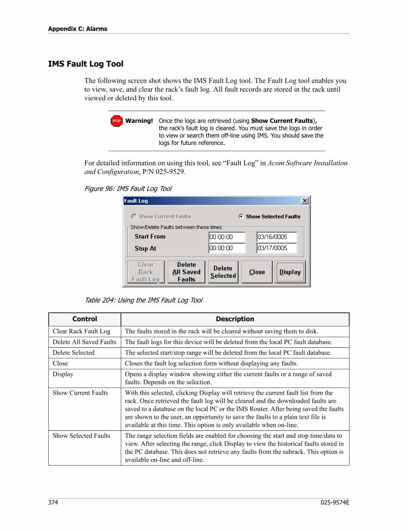
Appendix C: Alarms
374 025-9574E
IMS Fault Log Tool
The following screen shot shows the IMS Fault Log tool. The Fault Log tool enables you to view, save, and clear the rack’s fault log. All fault records are stored in the rack until viewed or deleted by this tool.
For detailed information on using this tool, see “Fault Log” in Acom Software Installation and Configuration, P/N 025-9529.
Figure 96: IMS Fault Log Tool
Table 204: Using the IMS Fault Log Tool
Warning! Once the logs are retrieved (using Show Current Faults), the rack's fault log is cleared. You must save the logs in order to view or search them off-line using IMS. You should save the logs for future reference.
STOP
Control Description
Clear Rack Fault Log The faults stored in the rack will be cleared without saving them to disk.Delete All Saved Faults The fault logs for this device will be deleted from the local PC fault database. Delete Selected The selected start/stop range will be deleted from the local PC fault database.Close Closes the fault log selection form without displaying any faults.Display Opens a display window showing either the current faults or a range of saved
faults. Depends on the selection.Show Current Faults With this selected, clicking Display will retrieve the current fault list from the
rack. Once retrieved the fault log will be cleared and the downloaded faults are saved to a database on the local PC or the IMS Router. After being saved the faults are shown to the user, an opportunity to save the faults to a plain text file is available at this time. This option is only available when on-line.
Show Selected Faults The range selection fields are enabled for choosing the start and stop time/data to view. After selecting the range, click Display to view the historical faults stored in the PC database. This does not retrieve any faults from the subrack. This option is available on-line and off-line.

375
IMS Fault Logs
Fault Log Header
Syntax
The fault log header uses the following syntax:
-------------------------------------------Device Time Date Alarm (State)
Device is the Acom identifier for the card with an alarm.
Time/Date is the time and date of the event.
Alarm is the type and name of alarm that occurred (see Table 205).
(State) is the event that the alarm changed to (Active/Inactive).
Alarm Types
Alarms will be one of three types: Input Alarms, Output Alarms, or Other Events.
Input Alarms
Prefixed by alarm text “Input Alarm (InActive)” or “Input Alarm (Active)”. Input alarms are created by digital inputs on the MSU card, an internal fault or message, or an E1/T1 fault.
For a complete list of fault log input alarms, see Fault Log Input Alarms on page 377.
Output Alarms
Prefixed by alarm text “Output Alarm (InActive)” or “Output Alarm (Active)”. Output alarms are created as a result of one or more connected/mapped input alarms. They may trigger LEDs, relays, E1/T1 alarms, or internal messages. See the Output alarm list for a complete description of the output alarms and their meaning.
For a complete list of fault log output alarms, see Fault Log Output Alarms on page 382.
Other Events
Other internal messages are logged to the fault log as they happen. Here is a description of some common events.
Alarm Names
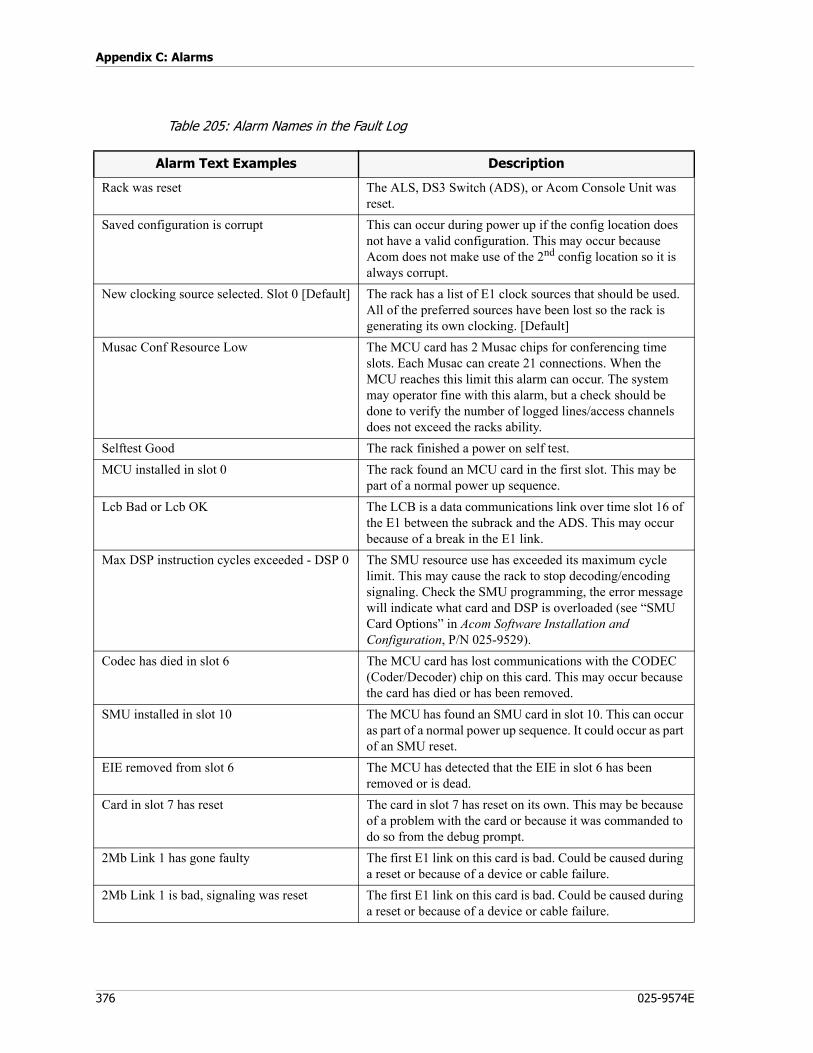
Appendix C: Alarms
376 025-9574E
Table 205: Alarm Names in the Fault Log
Alarm Text Examples Description
Rack was reset The ALS, DS3 Switch (ADS), or Acom Console Unit was reset.
Saved configuration is corrupt This can occur during power up if the config location does not have a valid configuration. This may occur because Acom does not make use of the 2nd config location so it is always corrupt.
New clocking source selected. Slot 0 [Default] The rack has a list of E1 clock sources that should be used. All of the preferred sources have been lost so the rack is generating its own clocking. [Default]
Musac Conf Resource Low The MCU card has 2 Musac chips for conferencing time slots. Each Musac can create 21 connections. When the MCU reaches this limit this alarm can occur. The system may operator fine with this alarm, but a check should be done to verify the number of logged lines/access channels does not exceed the racks ability.
Selftest Good The rack finished a power on self test.MCU installed in slot 0 The rack found an MCU card in the first slot. This may be
part of a normal power up sequence.Lcb Bad or Lcb OK The LCB is a data communications link over time slot 16 of
the E1 between the subrack and the ADS. This may occur because of a break in the E1 link.
Max DSP instruction cycles exceeded - DSP 0 The SMU resource use has exceeded its maximum cycle limit. This may cause the rack to stop decoding/encoding signaling. Check the SMU programming, the error message will indicate what card and DSP is overloaded (see “SMU Card Options” in Acom Software Installation and Configuration, P/N 025-9529).
Codec has died in slot 6 The MCU card has lost communications with the CODEC (Coder/Decoder) chip on this card. This may occur because the card has died or has been removed.
SMU installed in slot 10 The MCU has found an SMU card in slot 10. This can occur as part of a normal power up sequence. It could occur as part of an SMU reset.
EIE removed from slot 6 The MCU has detected that the EIE in slot 6 has been removed or is dead.
Card in slot 7 has reset The card in slot 7 has reset on its own. This may be because of a problem with the card or because it was commanded to do so from the debug prompt.
2Mb Link 1 has gone faulty The first E1 link on this card is bad. Could be caused during a reset or because of a device or cable failure.
2Mb Link 1 is bad, signaling was reset The first E1 link on this card is bad. Could be caused during a reset or because of a device or cable failure.
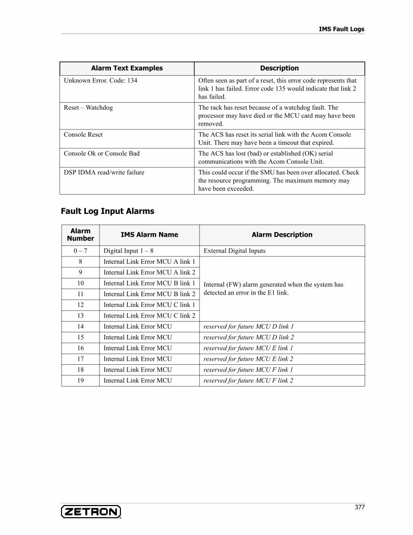
377
IMS Fault Logs
Fault Log Input Alarms
Unknown Error. Code: 134 Often seen as part of a reset, this error code represents that link 1 has failed. Error code 135 would indicate that link 2 has failed.
Reset – Watchdog The rack has reset because of a watchdog fault. The processor may have died or the MCU card may have been removed.
Console Reset The ACS has reset its serial link with the Acom Console Unit. There may have been a timeout that expired.
Console Ok or Console Bad The ACS has lost (bad) or established (OK) serial communications with the Acom Console Unit.
DSP IDMA read/write failure This could occur if the SMU has been over allocated. Check the resource programming. The maximum memory may have been exceeded.
Alarm Number IMS Alarm Name Alarm Description
0 – 7 Digital Input 1 – 8 External Digital Inputs8 Internal Link Error MCU A link 1
Internal (FW) alarm generated when the system has detected an error in the E1 link.
9 Internal Link Error MCU A link 210 Internal Link Error MCU B link 111 Internal Link Error MCU B link 212 Internal Link Error MCU C link 113 Internal Link Error MCU C link 214 Internal Link Error MCU reserved for future MCU D link 115 Internal Link Error MCU reserved for future MCU D link 216 Internal Link Error MCU reserved for future MCU E link 117 Internal Link Error MCU reserved for future MCU E link 218 Internal Link Error MCU reserved for future MCU F link 119 Internal Link Error MCU reserved for future MCU F link 2
Alarm Text Examples Description
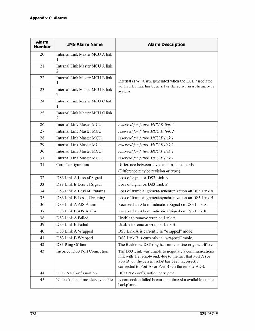
Appendix C: Alarms
378 025-9574E
20 Internal Link Master MCU A link 1
Internal (FW) alarm generated when the LCB associated with an E1 link has been set as the active in a changeover system.
21 Internal Link Master MCU A link 2
22 Internal Link Master MCU B link 1
23 Internal Link Master MCU B link 2
24 Internal Link Master MCU C link 1
25 Internal Link Master MCU C link 2
26 Internal Link Master MCU reserved for future MCU D link 127 Internal Link Master MCU reserved for future MCU D link 228 Internal Link Master MCU reserved for future MCU E link 129 Internal Link Master MCU reserved for future MCU E link 230 Internal Link Master MCU reserved for future MCU F link 131 Internal Link Master MCU reserved for future MCU F link 231 Card Configuration Difference between saved and installed cards.
(Difference may be revision or type.)32 DS3 Link A Loss of Signal Loss of signal on DS3 Link A33 DS3 Link B Loss of Signal Loss of signal on DS3 Link B34 DS3 Link A Loss of Framing Loss of frame alignment/synchronization on DS3 Link A35 DS3 Link B Loss of Framing Loss of frame alignment/synchronization on DS3 Link B36 DS3 Link A AIS Alarm Received an Alarm Indication Signal on DS3 Link A.37 DS3 Link B AIS Alarm Received an Alarm Indication Signal on DS3 Link B.38 DS3 Link A Failed Unable to remove wrap on Link A.39 DS3 Link B Failed Unable to remove wrap on Link B.40 DS3 Link A Wrapped DS3 Link A is currently in “wrapped” mode.41 DS3 Link B Wrapped DS3 Link B is currently in “wrapped” mode.42 DS3 Ring Offline The Backbone DS3 ring has come online or gone offline.43 Incorrect DS3 Port Connection The DS3 Link was unable to negotiate a communications
link with the remote end, due to the fact that Port A (or Port B) on the current ADS has been incorrectly connected to Port A (or Port B) on the remote ADS.
44 DCU NV Configuration DCU NV configuration corrupted45 No backplane time slots available A connection failed because no time slot available on the
backplane.
Alarm Number IMS Alarm Name Alarm Description
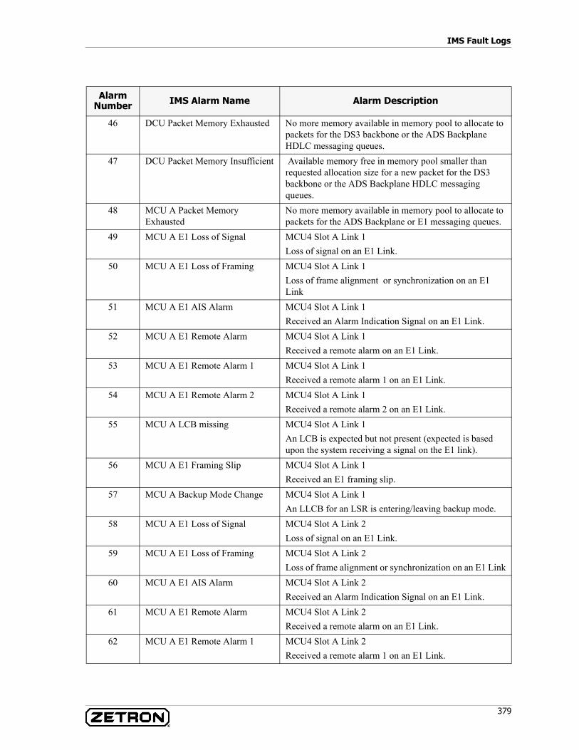
379
IMS Fault Logs
46 DCU Packet Memory Exhausted No more memory available in memory pool to allocate to packets for the DS3 backbone or the ADS Backplane HDLC messaging queues.
47 DCU Packet Memory Insufficient Available memory free in memory pool smaller than requested allocation size for a new packet for the DS3 backbone or the ADS Backplane HDLC messaging queues.
48 MCU A Packet Memory Exhausted
No more memory available in memory pool to allocate to packets for the ADS Backplane or E1 messaging queues.
49 MCU A E1 Loss of Signal MCU4 Slot A Link 1Loss of signal on an E1 Link.
50 MCU A E1 Loss of Framing MCU4 Slot A Link 1Loss of frame alignment or synchronization on an E1 Link
51 MCU A E1 AIS Alarm MCU4 Slot A Link 1Received an Alarm Indication Signal on an E1 Link.
52 MCU A E1 Remote Alarm MCU4 Slot A Link 1Received a remote alarm on an E1 Link.
53 MCU A E1 Remote Alarm 1 MCU4 Slot A Link 1Received a remote alarm 1 on an E1 Link.
54 MCU A E1 Remote Alarm 2 MCU4 Slot A Link 1Received a remote alarm 2 on an E1 Link.
55 MCU A LCB missing MCU4 Slot A Link 1An LCB is expected but not present (expected is based upon the system receiving a signal on the E1 link).
56 MCU A E1 Framing Slip MCU4 Slot A Link 1Received an E1 framing slip.
57 MCU A Backup Mode Change MCU4 Slot A Link 1An LLCB for an LSR is entering/leaving backup mode.
58 MCU A E1 Loss of Signal MCU4 Slot A Link 2Loss of signal on an E1 Link.
59 MCU A E1 Loss of Framing MCU4 Slot A Link 2Loss of frame alignment or synchronization on an E1 Link
60 MCU A E1 AIS Alarm MCU4 Slot A Link 2Received an Alarm Indication Signal on an E1 Link.
61 MCU A E1 Remote Alarm MCU4 Slot A Link 2Received a remote alarm on an E1 Link.
62 MCU A E1 Remote Alarm 1 MCU4 Slot A Link 2Received a remote alarm 1 on an E1 Link.
Alarm Number IMS Alarm Name Alarm Description

Appendix C: Alarms
380 025-9574E
63 MCU A E1 Remote Alarm 2 MCU4 Slot A Link 2Received a remote alarm 2 on an E1 Link.
64 MCU A LCB missing MCU4 Slot A Link 2An LCB is expected but not present (expected is based upon the system receiving a signal on the E1 link).
65 MCU A E1 Framing Slip MCU4 Slot A Link 2Received an E1 framing slip.
66 MCU A Backup Mode Change MCU4 Slot A Link 2An LLCB for an LSR is entering/leaving backup mode.
67-71 MCU A Spare reserved for future72 MCU B Packet Memory
ExhaustedNo more memory available in memory pool to allocate to packets for the ADS Backplane or E1 messaging queues.
73 MCU B E1 Loss of Signal MCU4 Slot B Link 1Loss of signal on an E1 Link.
74 MCU B E1 Loss of Framing MCU4 Slot B Link 1Loss of frame alignment or synchronization on an E1 Link
75 MCU B E1 AIS Alarm MCU4 Slot B Link 1Received an Alarm Indication Signal on an E1 Link.
76 MCU B E1 Remote Alarm MCU4 Slot B Link 1Received a remote alarm on an E1 Link.
77 MCU B E1 Remote Alarm 1 MCU4 Slot B Link 1Received a remote alarm 1 on an E1 Link.
78 MCU B E1 Remote Alarm 2 MCU4 Slot B Link 1Received a remote alarm 2 on an E1 Link.
79 MCU B LCB missing MCU4 Slot B Link 1An LCB is expected but not present (expected is based upon the system receiving a signal on the E1 link).
80 MCU B E1 Framing Slip MCU4 Slot B Link 1Received an E1 framing slip.
81 MCU B Backup Mode Change MCU4 Slot B Link 1An LLCB for an LSR is entering/leaving backup mode.
82 MCU B E1 Loss of Signal MCU4 Slot B Link 2Loss of signal on an E1 Link.
83 MCU B E1 Loss of Framing MCU4 Slot B Link 2- Loss of frame alignment or synchronization on an E1 Link
84 MCU B E1 AIS Alarm MCU4 Slot B Link 2- Received an Alarm Indication Signal on an E1 Link.
85 MCU B E1 Remote Alarm MCU4 Slot B Link 2- Received a remote alarm on an E1 Link.
Alarm Number IMS Alarm Name Alarm Description
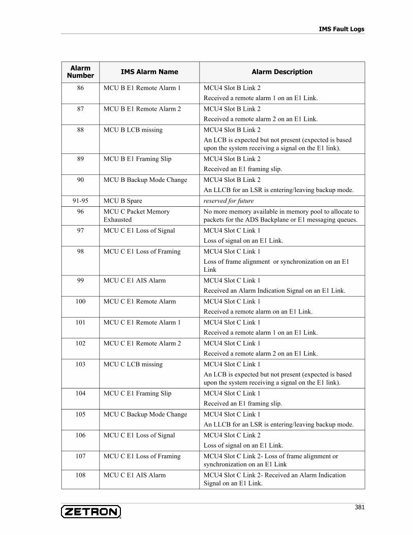
381
IMS Fault Logs
86 MCU B E1 Remote Alarm 1 MCU4 Slot B Link 2Received a remote alarm 1 on an E1 Link.
87 MCU B E1 Remote Alarm 2 MCU4 Slot B Link 2Received a remote alarm 2 on an E1 Link.
88 MCU B LCB missing MCU4 Slot B Link 2An LCB is expected but not present (expected is based upon the system receiving a signal on the E1 link).
89 MCU B E1 Framing Slip MCU4 Slot B Link 2Received an E1 framing slip.
90 MCU B Backup Mode Change MCU4 Slot B Link 2An LLCB for an LSR is entering/leaving backup mode.
91-95 MCU B Spare reserved for future96 MCU C Packet Memory
ExhaustedNo more memory available in memory pool to allocate to packets for the ADS Backplane or E1 messaging queues.
97 MCU C E1 Loss of Signal MCU4 Slot C Link 1Loss of signal on an E1 Link.
98 MCU C E1 Loss of Framing MCU4 Slot C Link 1Loss of frame alignment or synchronization on an E1 Link
99 MCU C E1 AIS Alarm MCU4 Slot C Link 1Received an Alarm Indication Signal on an E1 Link.
100 MCU C E1 Remote Alarm MCU4 Slot C Link 1Received a remote alarm on an E1 Link.
101 MCU C E1 Remote Alarm 1 MCU4 Slot C Link 1Received a remote alarm 1 on an E1 Link.
102 MCU C E1 Remote Alarm 2 MCU4 Slot C Link 1Received a remote alarm 2 on an E1 Link.
103 MCU C LCB missing MCU4 Slot C Link 1An LCB is expected but not present (expected is based upon the system receiving a signal on the E1 link).
104 MCU C E1 Framing Slip MCU4 Slot C Link 1Received an E1 framing slip.
105 MCU C Backup Mode Change MCU4 Slot C Link 1An LLCB for an LSR is entering/leaving backup mode.
106 MCU C E1 Loss of Signal MCU4 Slot C Link 2Loss of signal on an E1 Link.
107 MCU C E1 Loss of Framing MCU4 Slot C Link 2- Loss of frame alignment or synchronization on an E1 Link
108 MCU C E1 AIS Alarm MCU4 Slot C Link 2- Received an Alarm Indication Signal on an E1 Link.
Alarm Number IMS Alarm Name Alarm Description

Appendix C: Alarms
382 025-9574E
Fault Log Output Alarms
109 MCU C E1 Remote Alarm MCU4 Slot C Link 2- Received a remote alarm on an E1 Link.
110 MCU C E1 Remote Alarm 1 MCU4 Slot C Link 2Received a remote alarm 1 on an E1 Link.
111 MCU C E1 Remote Alarm 2 MCU4 Slot C Link 2Received a remote alarm 2 on an E1 Link.
112 MCU C LCB missing MCU4 Slot C Link 2An LCB is expected but not present (expected is based upon the system receiving a signal on the E1 link).
113 MCU C E1 Framing Slip MCU4 Slot C Link 2Received an E1 framing slip.
114 MCU C Backup Mode Change MCU4 Slot C Link 2An LLCB for an LSR is entering/leaving backup mode.
115-119 MCU C Spare reserved for future120 DCU Boot Error Error starting DCU code, running from backup or failsafe
image121 2Mb Clock Source Error A 2Mb clock source configured to generate an alarm has
failed.
Alarm Number Function
0 Urgent Alarm1 Non-urgent Alarm2 Information Alarm
3-10 Represents External Digital Output 1-811-16 Internal System Select.
(Used to tell the DS3 that the LCB is the selected active for a changeover. Usually driven by a digital input that is wired to a CCC changeover controller.)11 – MCU A, E1 Link 112 – MCU A, E1 Link 213 – MCU B, E1 Link 114 – MCU B, E1 Link 215 – MCU C, E1 Link 116 – MCU C, E1 Link 2
Alarm Number IMS Alarm Name Alarm Description
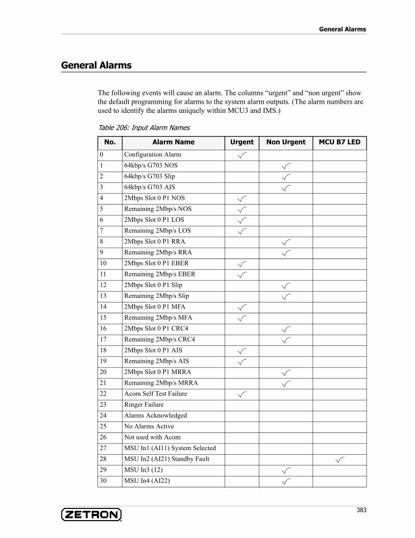
383
General Alarms
General Alarms
The following events will cause an alarm. The columns “urgent” and “non urgent” show the default programming for alarms to the system alarm outputs. (The alarm numbers are used to identify the alarms uniquely within MCU3 and IMS.)
Table 206: Input Alarm Names
No. Alarm Name Urgent Non Urgent MCU B7 LED
0 Configuration Alarm1 64kbp/s G703 NOS2 64kbp/s G703 Slip3 64kbp/s G703 AIS4 2Mbps Slot 0 P1 NOS5 Remaining 2Mbp/s NOS6 2Mbps Slot 0 P1 LOS7 Remaining 2Mbp/s LOS8 2Mbps Slot 0 P1 RRA9 Remaining 2Mbp/s RRA10 2Mbps Slot 0 P1 EBER11 Remaining 2Mbp/s EBER12 2Mbps Slot 0 P1 Slip13 Remaining 2Mbp/s Slip14 2Mbps Slot 0 P1 MFA15 Remaining 2Mbp/s MFA16 2Mbps Slot 0 P1 CRC417 Remaining 2Mbp/s CRC418 2Mbps Slot 0 P1 AIS19 Remaining 2Mbp/s AIS20 2Mbps Slot 0 P1 MRRA21 Remaining 2Mbp/s MRRA22 Acom Self Test Failure23 Ringer Failure24 Alarms Acknowledged25 No Alarms Active26 Not used with Acom27 MSU In1 (AI11) System Selected28 MSU In2 (AI21) Standby Fault29 MSU In3 (12)30 MSU In4 (AI22)
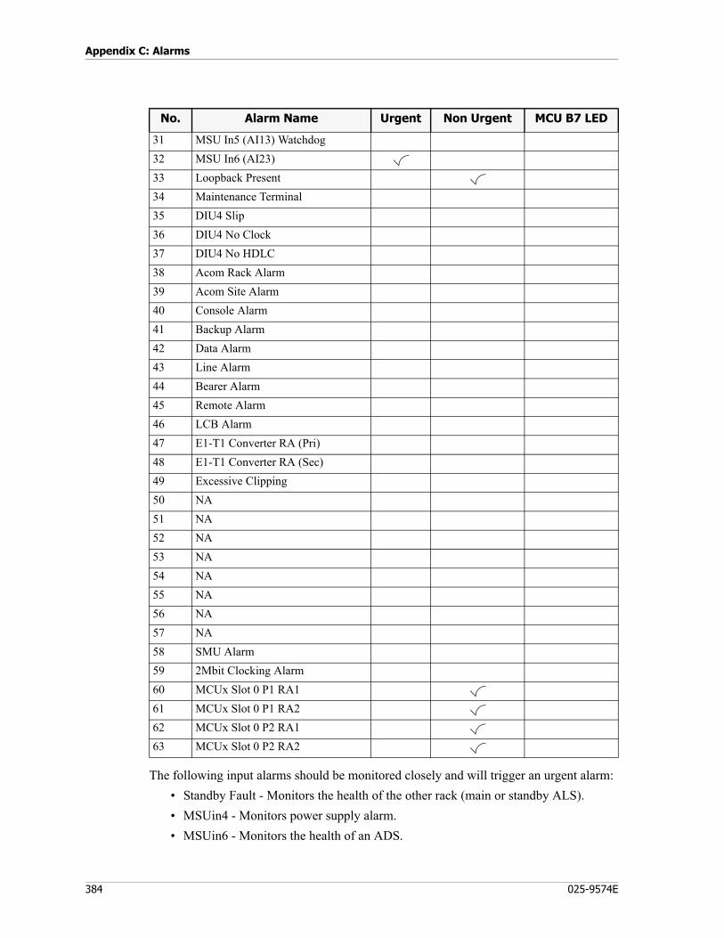
Appendix C: Alarms
384 025-9574E
The following input alarms should be monitored closely and will trigger an urgent alarm:• Standby Fault - Monitors the health of the other rack (main or standby ALS).• MSUin4 - Monitors power supply alarm.• MSUin6 - Monitors the health of an ADS.
31 MSU In5 (AI13) Watchdog32 MSU In6 (AI23)33 Loopback Present34 Maintenance Terminal35 DIU4 Slip 36 DIU4 No Clock37 DIU4 No HDLC 38 Acom Rack Alarm39 Acom Site Alarm40 Console Alarm41 Backup Alarm42 Data Alarm43 Line Alarm44 Bearer Alarm45 Remote Alarm46 LCB Alarm47 E1-T1 Converter RA (Pri)48 E1-T1 Converter RA (Sec)49 Excessive Clipping50 NA51 NA52 NA53 NA54 NA55 NA56 NA57 NA58 SMU Alarm59 2Mbit Clocking Alarm60 MCUx Slot 0 P1 RA161 MCUx Slot 0 P1 RA262 MCUx Slot 0 P2 RA163 MCUx Slot 0 P2 RA2
No. Alarm Name Urgent Non Urgent MCU B7 LED
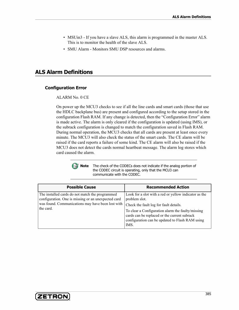
385
ALS Alarm Definitions
• MSUin3 - If you have a slave ALS, this alarm is programmed in the master ALS. This is to monitor the health of the slave ALS.
• SMU Alarm - Monitors SMU DSP resources and alarms.
ALS Alarm Definitions
Configuration Error
ALARM No. 0 CE
On power up the MCU3 checks to see if all the line cards and smart cards (those that use the HDLC backplane bus) are present and configured according to the setup stored in the configuration Flash RAM. If any change is detected, then the “Configuration Error” alarm is made active. The alarm is only cleared if the configuration is updated (using IMS), or the subrack configuration is changed to match the configuration saved in Flash RAM. During normal operation, the MCU3 checks that all cards are present at least once every minute. The MCU3 will also check the status of the smart cards. The CE alarm will be raised if the card reports a failure of some kind. The CE alarm will also be raised if the MCU3 does not detect the cards normal heartbeat message. The alarm log stores which card caused the alarm.
Note The check of the CODECs does not indicate if the analog portion of the CODEC circuit is operating, only that the MCU3 can communicate with the CODEC.
Possible Cause Recommended Action
The installed cards do not match the programmed configuration. One is missing or an unexpected card was found. Communications may have been lost with the card.
Look for a slot with a red or yellow indicator as the problem slot. Check the fault log for fault details. To clear a Configuration alarm the faulty/missing cards can be replaced or the current subrack configuration can be updated to Flash RAM using IMS.
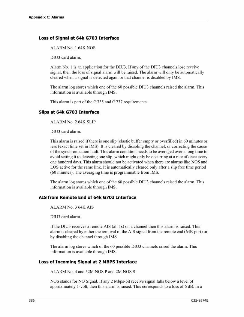
Appendix C: Alarms
386 025-9574E
Loss of Signal at 64k G703 Interface
ALARM No. 1 64K NOS
DIU3 card alarm.
Alarm No. 1 is an application for the DIU3. If any of the DIU3 channels lose receive signal, then the loss of signal alarm will be raised. The alarm will only be automatically cleared when a signal is detected again or that channel is disabled by IMS.
The alarm log stores which one of the 60 possible DIU3 channels raised the alarm. This information is available through IMS.
This alarm is part of the G.735 and G.737 requirements.
Slips at 64k G703 Interface
ALARM No. 2 64K SLIP
DIU3 card alarm.
This alarm is raised if there is one slip (elastic buffer empty or overfilled) in 60 minutes or less (exact time set in IMS). It is cleared by disabling the channel, or correcting the cause of the synchronization fault. This alarm condition needs to be averaged over a long time to avoid setting it to detecting one slip, which might only be occurring at a rate of once every one hundred days. This alarm should not be activated when there are alarms like NOS and LOS active for the same link. It is automatically cleared only after a slip free time period (60 minutes). The averaging time is programmable from IMS.
The alarm log stores which one of the 60 possible DIU3 channels raised the alarm. This information is available through IMS.
AIS from Remote End of 64k G703 Interface
ALARM No. 3 64K AIS
DIU3 card alarm.
If the DIU3 receives a remote AIS (all 1s) on a channel then this alarm is raised. This alarm is cleared by either the removal of the AIS signal from the remote end (64K port) or by disabling the channel through IMS.
The alarm log stores which of the 60 possible DIU3 channels raised the alarm. This information is available through IMS.
Loss of Incoming Signal at 2 MBPS Interface
ALARM No. 4 and 52M NOS P and 2M NOS S
NOS stands for NO Signal. If any 2 Mbps-bit receive signal falls below a level of approximately 1-volt, then this alarm is raised. This corresponds to a loss of 6 dB. In a
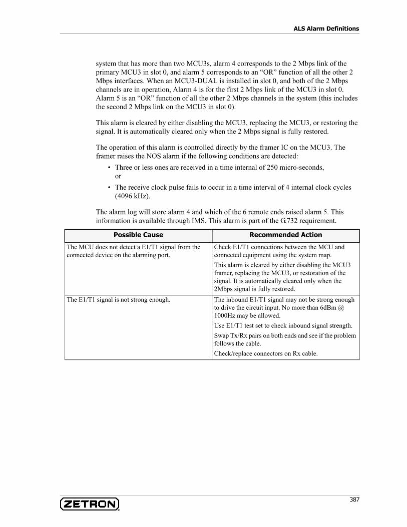
387
ALS Alarm Definitions
system that has more than two MCU3s, alarm 4 corresponds to the 2 Mbps link of the primary MCU3 in slot 0, and alarm 5 corresponds to an “OR” function of all the other 2 Mbps interfaces. When an MCU3-DUAL is installed in slot 0, and both of the 2 Mbps channels are in operation, Alarm 4 is for the first 2 Mbps link of the MCU3 in slot 0. Alarm 5 is an “OR” function of all the other 2 Mbps channels in the system (this includes the second 2 Mbps link on the MCU3 in slot 0).
This alarm is cleared by either disabling the MCU3, replacing the MCU3, or restoring the signal. It is automatically cleared only when the 2 Mbps signal is fully restored.
The operation of this alarm is controlled directly by the framer IC on the MCU3. The framer raises the NOS alarm if the following conditions are detected:
• Three or less ones are received in a time internal of 250 micro-seconds, or
• The receive clock pulse fails to occur in a time interval of 4 internal clock cycles (4096 kHz).
The alarm log will store alarm 4 and which of the 6 remote ends raised alarm 5. This information is available through IMS. This alarm is part of the G.732 requirement.
Possible Cause Recommended Action
The MCU does not detect a E1/T1 signal from the connected device on the alarming port.
Check E1/T1 connections between the MCU and connected equipment using the system map.This alarm is cleared by either disabling the MCU3 framer, replacing the MCU3, or restoration of the signal. It is automatically cleared only when the 2Mbps signal is fully restored.
The E1/T1 signal is not strong enough. The inbound E1/T1 signal may not be strong enough to drive the circuit input. No more than 6dBm @ 1000Hz may be allowed. Use E1/T1 test set to check inbound signal strength.Swap Tx/Rx pairs on both ends and see if the problem follows the cable. Check/replace connectors on Rx cable.
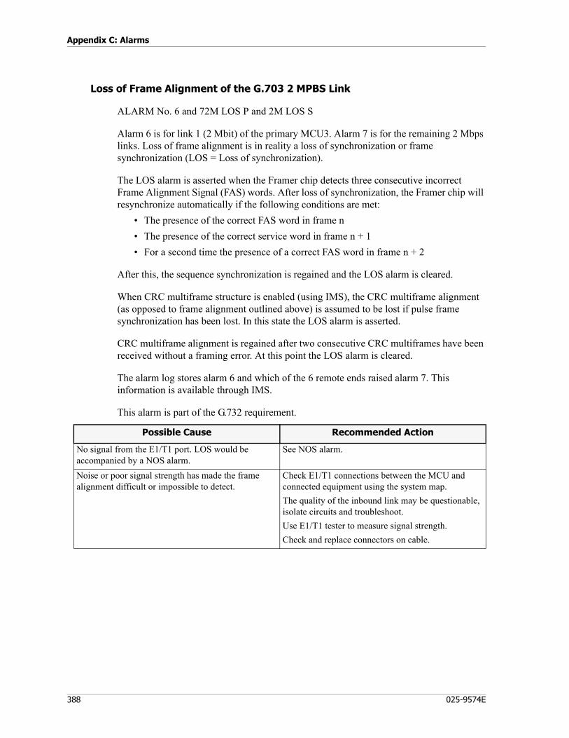
Appendix C: Alarms
388 025-9574E
Loss of Frame Alignment of the G.703 2 MPBS Link
ALARM No. 6 and 72M LOS P and 2M LOS S
Alarm 6 is for link 1 (2 Mbit) of the primary MCU3. Alarm 7 is for the remaining 2 Mbps links. Loss of frame alignment is in reality a loss of synchronization or frame synchronization (LOS = Loss of synchronization).
The LOS alarm is asserted when the Framer chip detects three consecutive incorrect Frame Alignment Signal (FAS) words. After loss of synchronization, the Framer chip will resynchronize automatically if the following conditions are met:
• The presence of the correct FAS word in frame n • The presence of the correct service word in frame n + 1 • For a second time the presence of a correct FAS word in frame n + 2
After this, the sequence synchronization is regained and the LOS alarm is cleared.
When CRC multiframe structure is enabled (using IMS), the CRC multiframe alignment (as opposed to frame alignment outlined above) is assumed to be lost if pulse frame synchronization has been lost. In this state the LOS alarm is asserted.
CRC multiframe alignment is regained after two consecutive CRC multiframes have been received without a framing error. At this point the LOS alarm is cleared.
The alarm log stores alarm 6 and which of the 6 remote ends raised alarm 7. This information is available through IMS.
This alarm is part of the G.732 requirement.
Possible Cause Recommended Action
No signal from the E1/T1 port. LOS would be accompanied by a NOS alarm.
See NOS alarm.
Noise or poor signal strength has made the frame alignment difficult or impossible to detect.
Check E1/T1 connections between the MCU and connected equipment using the system map. The quality of the inbound link may be questionable, isolate circuits and troubleshoot.Use E1/T1 tester to measure signal strength.Check and replace connectors on cable.
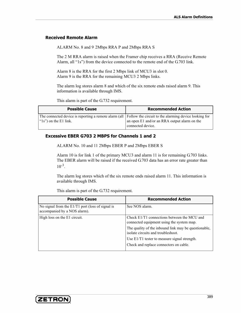
389
ALS Alarm Definitions
Received Remote Alarm
ALARM No. 8 and 9 2Mbps RRA P and 2Mbps RRA S
The 2 M RRA alarm is raised when the Framer chip receives a RRA (Receive Remote Alarm, all “1s”) from the device connected to the remote end of the G.703 link.
Alarm 8 is the RRA for the first 2 Mbps link of MCU3 in slot 0.Alarm 9 is the RRA for the remaining MCU3 2 Mbps links.
The alarm log stores alarm 8 and which of the six remote ends raised alarm 9. This information is available through IMS.
This alarm is part of the G.732 requirement.
Excessive EBER G703 2 MBPS for Channels 1 and 2
ALARM No. 10 and 11 2Mbps EBER P and 2Mbps EBER S
Alarm 10 is for link 1 of the primary MCU3 and alarm 11 is for remaining G.703 links. The EBER alarm will be raised if the received G.703 data has an error rate greater than 10-3.
The alarm log stores which of the six remote ends raised alarm 11. This information is available through IMS.
This alarm is part of the G.732 requirement.
Possible Cause Recommended Action
The connected device is reporting a remote alarm (all “1s”) on the E1 link.
Follow the circuit to the alarming device looking for an open E1 and/or an RRA output alarm on the connected device.
Possible Cause Recommended Action
No signal from the E1/T1 port (loss of signal is accompanied by a NOS alarm).
See NOS alarm.
High loss on the E1 circuit. Check E1/T1 connections between the MCU and connected equipment using the system map. The quality of the inbound link may be questionable, isolate circuits and troubleshoot.Use E1/T1 tester to measure signal strength.Check and replace connectors on cable.
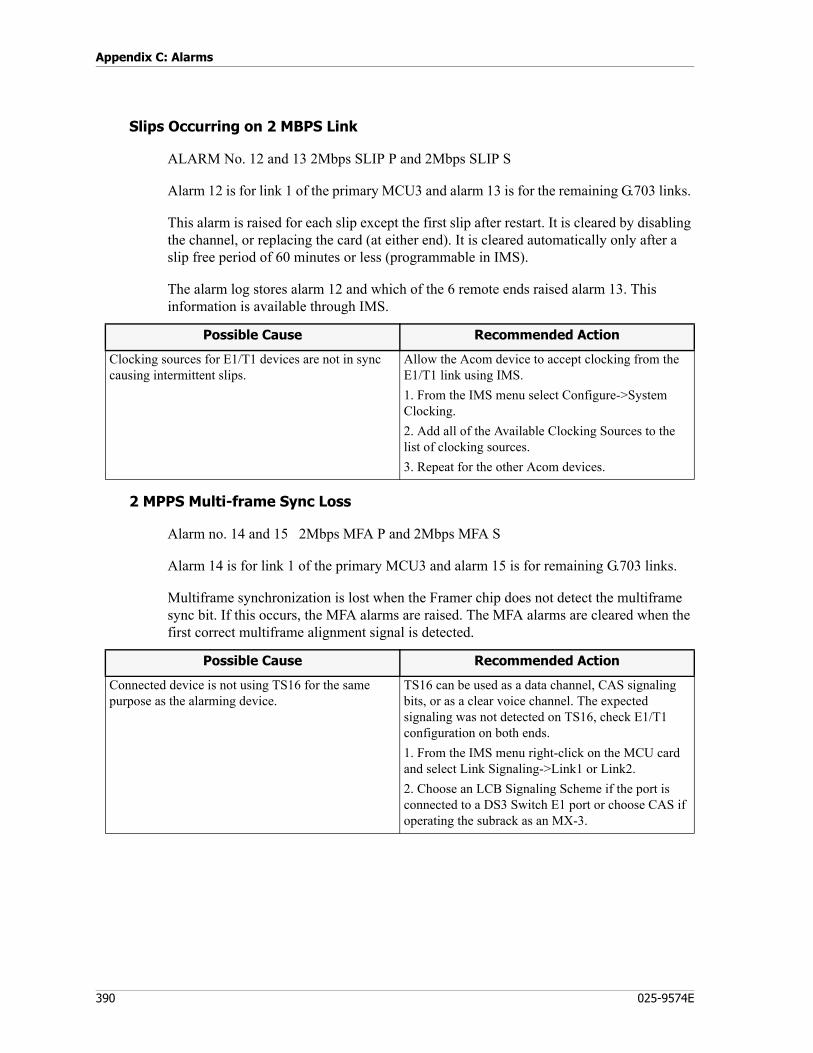
Appendix C: Alarms
390 025-9574E
Slips Occurring on 2 MBPS Link
ALARM No. 12 and 13 2Mbps SLIP P and 2Mbps SLIP S
Alarm 12 is for link 1 of the primary MCU3 and alarm 13 is for the remaining G.703 links.
This alarm is raised for each slip except the first slip after restart. It is cleared by disabling the channel, or replacing the card (at either end). It is cleared automatically only after a slip free period of 60 minutes or less (programmable in IMS).
The alarm log stores alarm 12 and which of the 6 remote ends raised alarm 13. This information is available through IMS.
2 MPPS Multi-frame Sync Loss
Alarm no. 14 and 15 2Mbps MFA P and 2Mbps MFA S
Alarm 14 is for link 1 of the primary MCU3 and alarm 15 is for remaining G.703 links.
Multiframe synchronization is lost when the Framer chip does not detect the multiframe sync bit. If this occurs, the MFA alarms are raised. The MFA alarms are cleared when the first correct multiframe alignment signal is detected.
Possible Cause Recommended Action
Clocking sources for E1/T1 devices are not in sync causing intermittent slips.
Allow the Acom device to accept clocking from the E1/T1 link using IMS. 1. From the IMS menu select Configure->System Clocking.2. Add all of the Available Clocking Sources to the list of clocking sources.3. Repeat for the other Acom devices.
Possible Cause Recommended Action
Connected device is not using TS16 for the same purpose as the alarming device.
TS16 can be used as a data channel, CAS signaling bits, or as a clear voice channel. The expected signaling was not detected on TS16, check E1/T1 configuration on both ends.1. From the IMS menu right-click on the MCU card and select Link Signaling->Link1 or Link2.2. Choose an LCB Signaling Scheme if the port is connected to a DS3 Switch E1 port or choose CAS if operating the subrack as an MX-3.
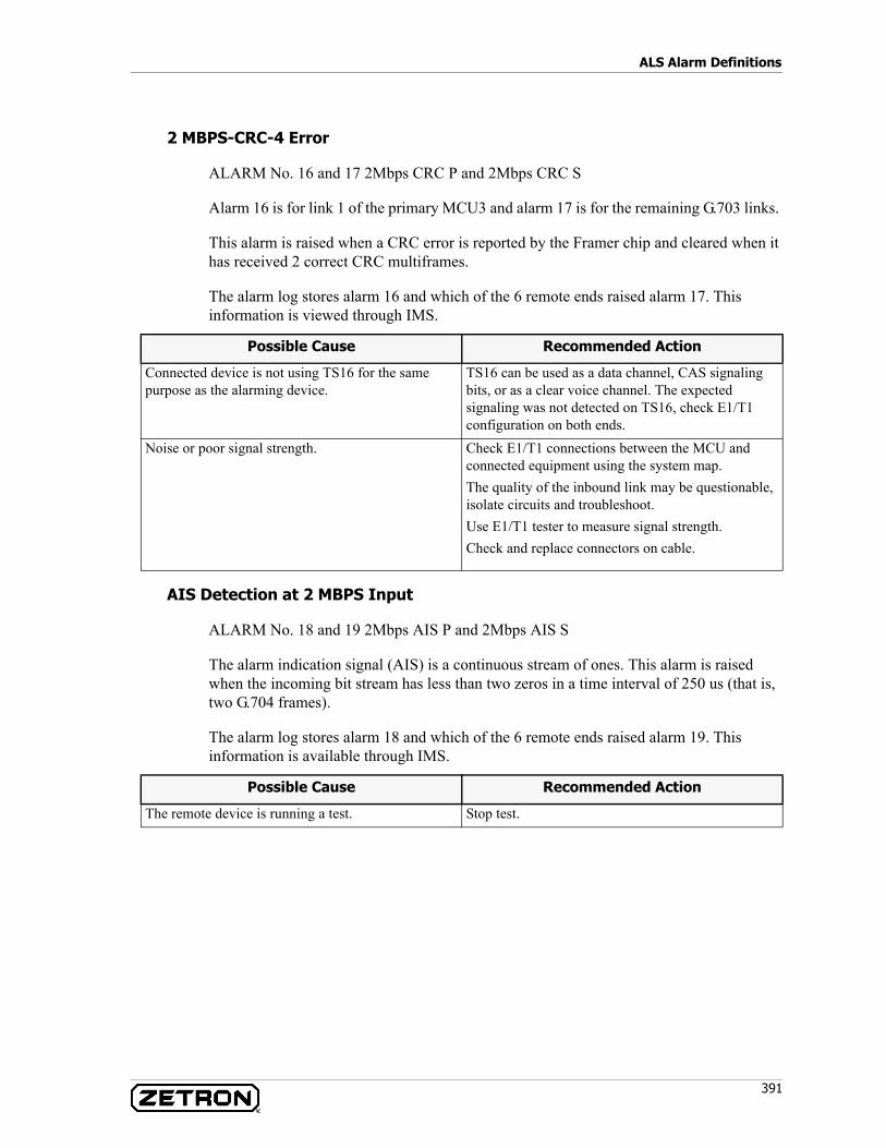
391
ALS Alarm Definitions
2 MBPS-CRC-4 Error
ALARM No. 16 and 17 2Mbps CRC P and 2Mbps CRC S
Alarm 16 is for link 1 of the primary MCU3 and alarm 17 is for the remaining G.703 links.
This alarm is raised when a CRC error is reported by the Framer chip and cleared when it has received 2 correct CRC multiframes.
The alarm log stores alarm 16 and which of the 6 remote ends raised alarm 17. This information is viewed through IMS.
AIS Detection at 2 MBPS Input
ALARM No. 18 and 19 2Mbps AIS P and 2Mbps AIS S
The alarm indication signal (AIS) is a continuous stream of ones. This alarm is raised when the incoming bit stream has less than two zeros in a time interval of 250 us (that is, two G.704 frames).
The alarm log stores alarm 18 and which of the 6 remote ends raised alarm 19. This information is available through IMS.
Possible Cause Recommended Action
Connected device is not using TS16 for the same purpose as the alarming device.
TS16 can be used as a data channel, CAS signaling bits, or as a clear voice channel. The expected signaling was not detected on TS16, check E1/T1 configuration on both ends.
Noise or poor signal strength. Check E1/T1 connections between the MCU and connected equipment using the system map. The quality of the inbound link may be questionable, isolate circuits and troubleshoot.Use E1/T1 tester to measure signal strength.Check and replace connectors on cable.
Possible Cause Recommended Action
The remote device is running a test. Stop test.
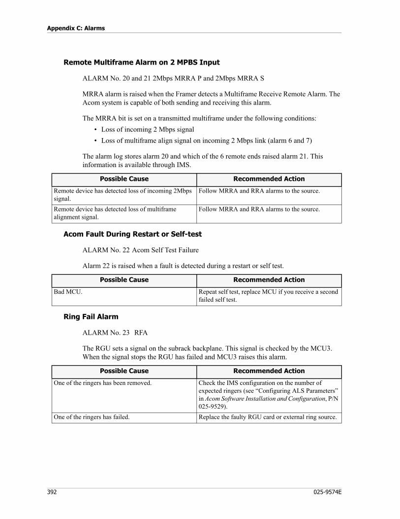
Appendix C: Alarms
392 025-9574E
Remote Multiframe Alarm on 2 MPBS Input
ALARM No. 20 and 21 2Mbps MRRA P and 2Mbps MRRA S
MRRA alarm is raised when the Framer detects a Multiframe Receive Remote Alarm. The Acom system is capable of both sending and receiving this alarm.
The MRRA bit is set on a transmitted multiframe under the following conditions:• Loss of incoming 2 Mbps signal• Loss of multiframe align signal on incoming 2 Mbps link (alarm 6 and 7)
The alarm log stores alarm 20 and which of the 6 remote ends raised alarm 21. This information is available through IMS.
Acom Fault During Restart or Self-test
ALARM No. 22 Acom Self Test Failure
Alarm 22 is raised when a fault is detected during a restart or self test.
Ring Fail Alarm
ALARM No. 23 RFA
The RGU sets a signal on the subrack backplane. This signal is checked by the MCU3. When the signal stops the RGU has failed and MCU3 raises this alarm.
Possible Cause Recommended Action
Remote device has detected loss of incoming 2Mbps signal.
Follow MRRA and RRA alarms to the source.
Remote device has detected loss of multiframe alignment signal.
Follow MRRA and RRA alarms to the source.
Possible Cause Recommended Action
Bad MCU. Repeat self test, replace MCU if you receive a second failed self test.
Possible Cause Recommended Action
One of the ringers has been removed. Check the IMS configuration on the number of expected ringers (see “Configuring ALS Parameters” in Acom Software Installation and Configuration, P/N 025-9529).
One of the ringers has failed. Replace the faulty RGU card or external ring source.
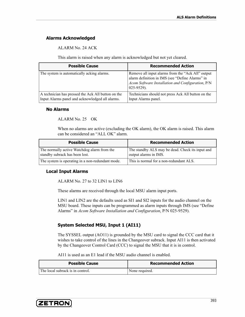
393
ALS Alarm Definitions
Alarms Acknowledged
ALARM No. 24 ACK
This alarm is raised when any alarm is acknowledged but not yet cleared.
No Alarms
ALARM No. 25 OK
When no alarms are active (excluding the OK alarm), the OK alarm is raised. This alarm can be considered an “ALL OK” alarm.
Local Input Alarms
ALARM No. 27 to 32 LIN1 to LIN6
These alarms are received through the local MSU alarm input ports.
LIN1 and LIN2 are the defaults used as SI1 and SI2 inputs for the audio channel on the MSU board. These inputs can be programmed as alarm inputs through IMS (see “Define Alarms” in Acom Software Installation and Configuration, P/N 025-9529).
System Selected MSU, Input 1 (AI11)
The SYSSEL output (AO11) is grounded by the MSU card to signal the CCC card that it wishes to take control of the lines in the Changeover subrack. Input AI11 is then activated by the Changeover Control Card (CCC) to signal the MSU that it is in control.
AI11 is used as an E1 lead if the MSU audio channel is enabled.
Possible Cause Recommended Action
The system is automatically acking alarms. Remove all input alarms from the “Ack All” output alarm definition in IMS (see “Define Alarms” in Acom Software Installation and Configuration, P/N 025-9529).
A technician has pressed the Ack All button on the Input Alarms panel and acknowledged all alarms.
Technicians should not press Ack All button on the Input Alarms panel.
Possible Cause Recommended Action
The normally active Watchdog alarm from the standby subrack has been lost.
The standby ALS may be dead. Check its input and output alarms in IMS.
The system is operating in a non-redundant mode. This is normal for a non-redundant ALS.
Possible Cause Recommended Action
The local subrack is in control. None required.

Appendix C: Alarms
394 025-9574E
Standby Fault MSU, Input 2 (AI21)
This is the health alarm of the standby subrack. This input is expected to be normally inactive and if it becomes active a fault in the standby rack is assumed. Like the Watchdog alarm it provides communication between main and standby MSU cards. It is common to duplicate the same type of alarm mapping to the Standby Fault alarm as the Urgent Alarm Output so as to switch control if an Urgent alarm was to occur.
AI11 is used as an E2 lead if the MSU audio channel is enabled.
MSU Input 3 (AI12)
This is an MSU input alarm that may be used for other purposes such as monitoring the power supply alarms.
MSU Input 4 (AI22)
This is an MSU input alarm that may be used for other purposes such as monitoring the power supply alarms.
Watchdog, MSU Input 5 (AI13)
Should the Primary MCU card in the ALS go dead, or the MSU lose power, this output will go inactive to indicate it has failed. In addition to these two non-configurable triggers, additional alarm inputs can be mapped to this MSU output to trigger a changeover (see “Define Alarms” in Acom Software Installation and Configuration, P/N 025-9529). It is common to connect all operational alarms to the Standby Fault output and leave only the loss of power and failure of a primary MCU to trigger the watchdog. The Watchdog input (AI13) monitors the Watchdog output of the other subrack. If this input goes high (inactive) the MSU will demand control by asserting the SYSSEL Output (AO11).
MSU Input 6 (AI23)
The AI23 input is commonly used to detect a problem with the E1 link associated with the local subrack. The backbone switch (ADS) connected to the E1 ports of the Primary MCU card provides this signal. It provides a faster indication of a lost E1 than waiting for a LOS, NOS, or RRA signal on the E1 link and will result in a quicker changeover between subracks.
Possible Cause Recommended Action
The redundant standby subrack has a problem. Use IMS to view the input/output alarms of the standby subrack.
Note The Watchdog output (AO13) is in an active state under normal operation. For this reason a redundant ALS will never have the “All OK” alarm active.

395
ALS Alarm Definitions
Test Condition
ALARM No. 33 TEST
This alarm is raised when a loopback test is initiated from the maintenance terminal.
Maintenance Terminal Active
ALARM No. 34 MAINT
This alarm is raised when a maintenance terminal is opened on the ALS.
DIU4 Alarms
ALARM No. 35, 36, 37 DIU4 SLIPS, DIU4 NO CLOCK, DIU4 NO HDLC
These alarms are raised when the DIU4 board detects a slip, loss of clocking, or loss of HDLC (High-level Data Link Control) communication with the Primary MCU3.
ALARM No. 40 Console Alarm
Indicates a console from the local Operator SubRack (OSR) has lost serial communications with the console PC.
Possible Cause Recommended Action
A loopback test is underway on an E1 link in this subrack.
Use IMS to remove the loopback test. (See “Loopback” in Acom Software Installation and Configuration, P/N 025-9529).
Possible Cause Recommended Action
A local IMS connection is active with this subrack. Not a problem, indicates there is a local RS232 IMS session active.
Possible Cause Recommended Action
Console PC turned off. Check the power to the console PC and that it isturned on.
ACS application not running. Check that the ACS application is running and logged in. Acknowledge any popup messages it might display and check the status bar to verify communications with the Acom Console Unit.
Baud rate or serial settings wrong in DIU configuration.
Check the IMS and ACS configuration for the serial port and baud rate (see “Serial Port” in Acom Software Installation and Configuration, P/N 025-9529).
The physical RS422 port to the console PC is bad. Check DIU connection to console.
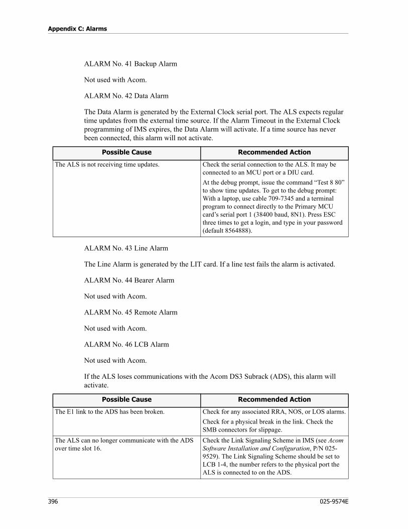
Appendix C: Alarms
396 025-9574E
ALARM No. 41 Backup Alarm
Not used with Acom.
ALARM No. 42 Data Alarm
The Data Alarm is generated by the External Clock serial port. The ALS expects regular time updates from the external time source. If the Alarm Timeout in the External Clock programming of IMS expires, the Data Alarm will activate. If a time source has never been connected, this alarm will not activate.
ALARM No. 43 Line Alarm
The Line Alarm is generated by the LIT card. If a line test fails the alarm is activated.
ALARM No. 44 Bearer Alarm
Not used with Acom.
ALARM No. 45 Remote Alarm
Not used with Acom.
ALARM No. 46 LCB Alarm
Not used with Acom.
If the ALS loses communications with the Acom DS3 Subrack (ADS), this alarm will activate.
Possible Cause Recommended Action
The ALS is not receiving time updates. Check the serial connection to the ALS. It may be connected to an MCU port or a DIU card.At the debug prompt, issue the command “Test 8 80” to show time updates. To get to the debug prompt: With a laptop, use cable 709-7345 and a terminal program to connect directly to the Primary MCU card’s serial port 1 (38400 baud, 8N1). Press ESC three times to get a login, and type in your password (default 8564888).
Possible Cause Recommended Action
The E1 link to the ADS has been broken. Check for any associated RRA, NOS, or LOS alarms.Check for a physical break in the link. Check the SMB connectors for slippage.
The ALS can no longer communicate with the ADS over time slot 16.
Check the Link Signaling Scheme in IMS (see Acom Software Installation and Configuration, P/N 025-9529). The Link Signaling Scheme should be set to LCB 1-4, the number refers to the physical port the ALS is connected to on the ADS.
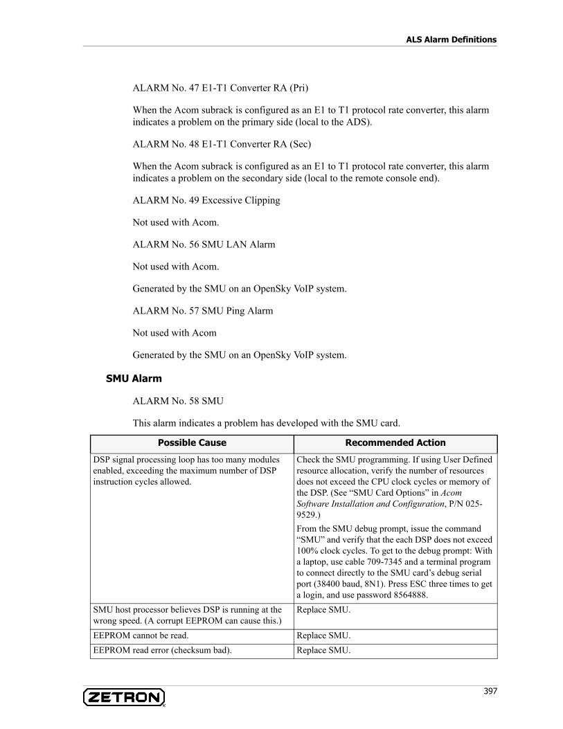
397
ALS Alarm Definitions
ALARM No. 47 E1-T1 Converter RA (Pri)
When the Acom subrack is configured as an E1 to T1 protocol rate converter, this alarm indicates a problem on the primary side (local to the ADS).
ALARM No. 48 E1-T1 Converter RA (Sec)
When the Acom subrack is configured as an E1 to T1 protocol rate converter, this alarm indicates a problem on the secondary side (local to the remote console end).
ALARM No. 49 Excessive Clipping
Not used with Acom.
ALARM No. 56 SMU LAN Alarm
Not used with Acom.
Generated by the SMU on an OpenSky VoIP system.
ALARM No. 57 SMU Ping Alarm
Not used with Acom
Generated by the SMU on an OpenSky VoIP system.
SMU Alarm
ALARM No. 58 SMU
This alarm indicates a problem has developed with the SMU card.
Possible Cause Recommended Action
DSP signal processing loop has too many modules enabled, exceeding the maximum number of DSP instruction cycles allowed.
Check the SMU programming. If using User Defined resource allocation, verify the number of resources does not exceed the CPU clock cycles or memory of the DSP. (See “SMU Card Options” in Acom Software Installation and Configuration, P/N 025-9529.)From the SMU debug prompt, issue the command “SMU” and verify that the each DSP does not exceed 100% clock cycles. To get to the debug prompt: With a laptop, use cable 709-7345 and a terminal program to connect directly to the SMU card’s debug serial port (38400 baud, 8N1). Press ESC three times to get a login, and use password 8564888.
SMU host processor believes DSP is running at the wrong speed. (A corrupt EEPROM can cause this.)
Replace SMU.
EEPROM cannot be read. Replace SMU.EEPROM read error (checksum bad). Replace SMU.
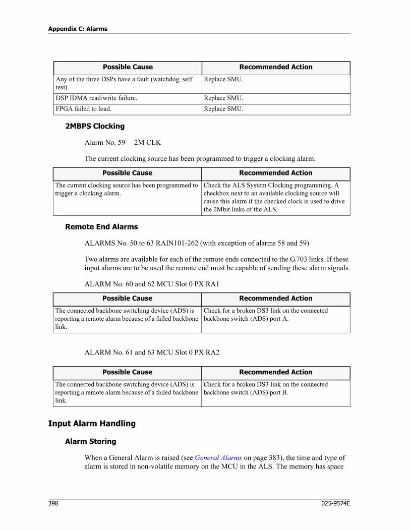
Appendix C: Alarms
398 025-9574E
2MBPS Clocking
Alarm No. 59 2M CLK
The current clocking source has been programmed to trigger a clocking alarm.
Remote End Alarms
ALARMS No. 50 to 63 RAIN101-262 (with exception of alarms 58 and 59)
Two alarms are available for each of the remote ends connected to the G.703 links. If these input alarms are to be used the remote end must be capable of sending these alarm signals.
ALARM No. 60 and 62 MCU Slot 0 PX RA1
ALARM No. 61 and 63 MCU Slot 0 PX RA2
Input Alarm Handling
Alarm Storing
When a General Alarm is raised (see General Alarms on page 383), the time and type of alarm is stored in non-volatile memory on the MCU in the ALS. The memory has space
Any of the three DSPs have a fault (watchdog, self test).
Replace SMU.
DSP IDMA read/write failure. Replace SMU.FPGA failed to load. Replace SMU.
Possible Cause Recommended Action
Possible Cause Recommended Action
The current clocking source has been programmed to trigger a clocking alarm.
Check the ALS System Clocking programming. A checkbox next to an available clocking source will cause this alarm if the checked clock is used to drive the 2Mbit links of the ALS.
Possible Cause Recommended Action
The connected backbone switching device (ADS) is reporting a remote alarm because of a failed backbone link.
Check for a broken DS3 link on the connected backbone switch (ADS) port A.
Possible Cause Recommended Action
The connected backbone switching device (ADS) is reporting a remote alarm because of a failed backbone link.
Check for a broken DS3 link on the connected backbone switch (ADS) port B.
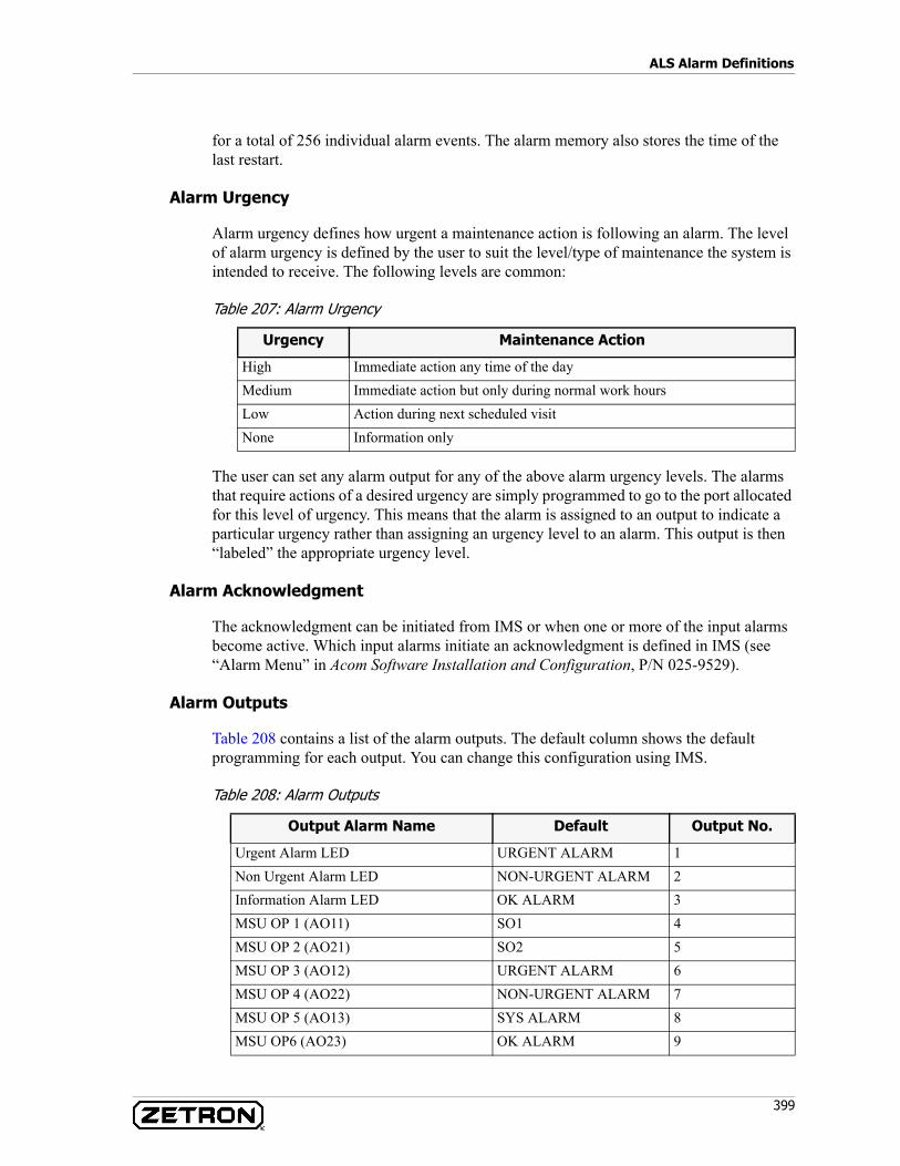
399
ALS Alarm Definitions
for a total of 256 individual alarm events. The alarm memory also stores the time of the last restart.
Alarm Urgency
Alarm urgency defines how urgent a maintenance action is following an alarm. The level of alarm urgency is defined by the user to suit the level/type of maintenance the system is intended to receive. The following levels are common:
Table 207: Alarm Urgency
The user can set any alarm output for any of the above alarm urgency levels. The alarms that require actions of a desired urgency are simply programmed to go to the port allocated for this level of urgency. This means that the alarm is assigned to an output to indicate a particular urgency rather than assigning an urgency level to an alarm. This output is then “labeled” the appropriate urgency level.
Alarm Acknowledgment
The acknowledgment can be initiated from IMS or when one or more of the input alarms become active. Which input alarms initiate an acknowledgment is defined in IMS (see “Alarm Menu” in Acom Software Installation and Configuration, P/N 025-9529).
Alarm Outputs
Table 208 contains a list of the alarm outputs. The default column shows the default programming for each output. You can change this configuration using IMS.
Table 208: Alarm Outputs
Urgency Maintenance Action
High Immediate action any time of the dayMedium Immediate action but only during normal work hoursLow Action during next scheduled visitNone Information only
Output Alarm Name Default Output No.
Urgent Alarm LED URGENT ALARM 1Non Urgent Alarm LED NON-URGENT ALARM 2Information Alarm LED OK ALARM 3MSU OP 1 (AO11) SO1 4MSU OP 2 (AO21) SO2 5MSU OP 3 (AO12) URGENT ALARM 6MSU OP 4 (AO22) NON-URGENT ALARM 7MSU OP 5 (AO13) SYS ALARM 8MSU OP6 (AO23) OK ALARM 9
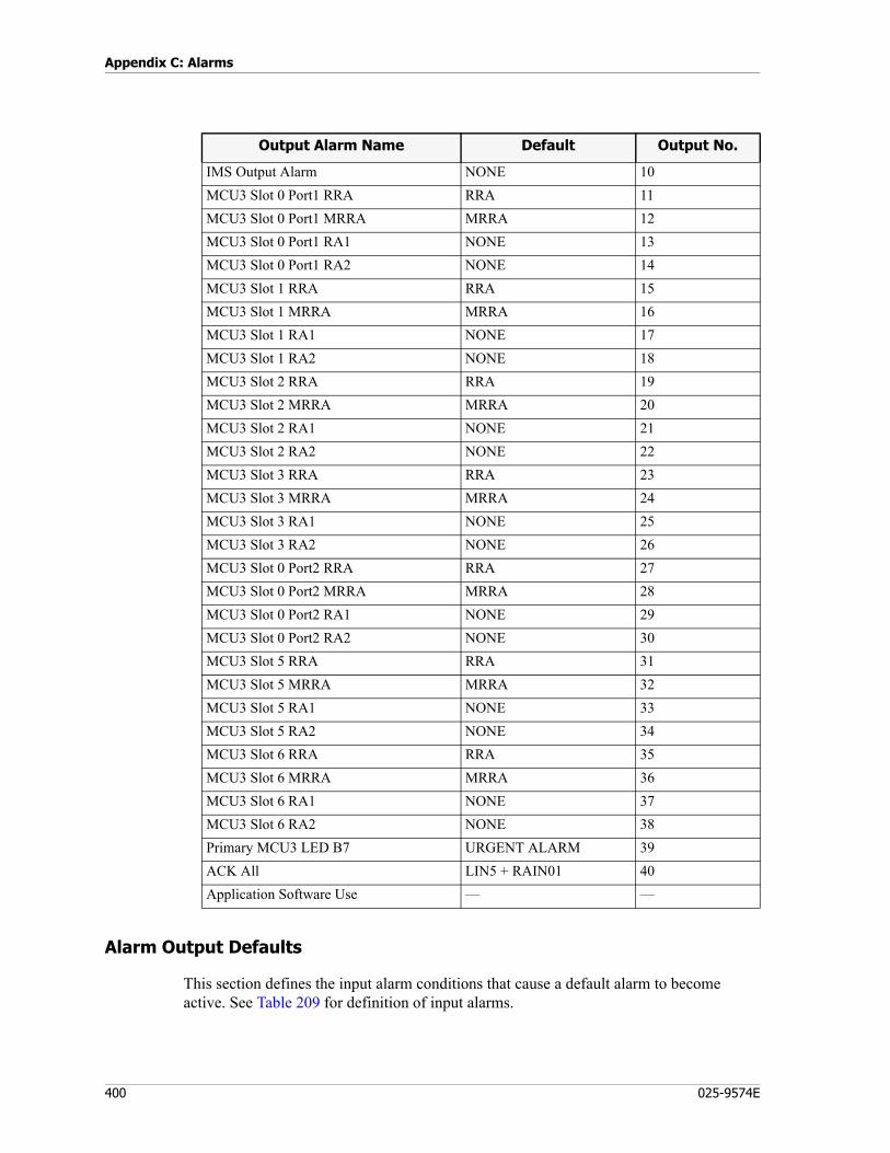
Appendix C: Alarms
400 025-9574E
Alarm Output Defaults
This section defines the input alarm conditions that cause a default alarm to become active. See Table 209 for definition of input alarms.
IMS Output Alarm NONE 10MCU3 Slot 0 Port1 RRA RRA 11MCU3 Slot 0 Port1 MRRA MRRA 12MCU3 Slot 0 Port1 RA1 NONE 13MCU3 Slot 0 Port1 RA2 NONE 14MCU3 Slot 1 RRA RRA 15MCU3 Slot 1 MRRA MRRA 16MCU3 Slot 1 RA1 NONE 17MCU3 Slot 1 RA2 NONE 18MCU3 Slot 2 RRA RRA 19MCU3 Slot 2 MRRA MRRA 20MCU3 Slot 2 RA1 NONE 21MCU3 Slot 2 RA2 NONE 22MCU3 Slot 3 RRA RRA 23MCU3 Slot 3 MRRA MRRA 24MCU3 Slot 3 RA1 NONE 25MCU3 Slot 3 RA2 NONE 26MCU3 Slot 0 Port2 RRA RRA 27MCU3 Slot 0 Port2 MRRA MRRA 28MCU3 Slot 0 Port2 RA1 NONE 29MCU3 Slot 0 Port2 RA2 NONE 30MCU3 Slot 5 RRA RRA 31MCU3 Slot 5 MRRA MRRA 32MCU3 Slot 5 RA1 NONE 33MCU3 Slot 5 RA2 NONE 34MCU3 Slot 6 RRA RRA 35MCU3 Slot 6 MRRA MRRA 36MCU3 Slot 6 RA1 NONE 37MCU3 Slot 6 RA2 NONE 38Primary MCU3 LED B7 URGENT ALARM 39ACK All LIN5 + RAIN01 40Application Software Use — —
Output Alarm Name Default Output No.
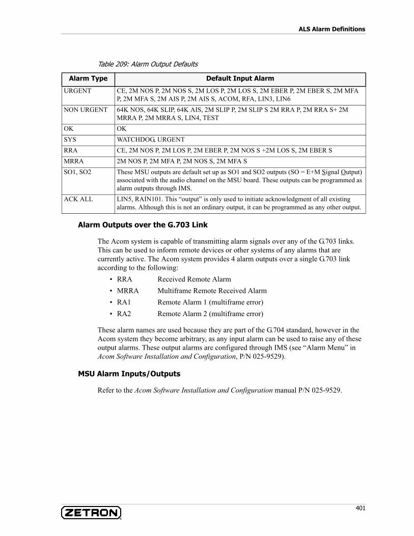
401
ALS Alarm Definitions
Table 209: Alarm Output Defaults
Alarm Outputs over the G.703 Link
The Acom system is capable of transmitting alarm signals over any of the G.703 links. This can be used to inform remote devices or other systems of any alarms that are currently active. The Acom system provides 4 alarm outputs over a single G.703 link according to the following:
• RRA Received Remote Alarm• MRRA Multiframe Remote Received Alarm• RA1 Remote Alarm 1 (multiframe error)• RA2 Remote Alarm 2 (multiframe error)
These alarm names are used because they are part of the G.704 standard, however in the Acom system they become arbitrary, as any input alarm can be used to raise any of these output alarms. These output alarms are configured through IMS (see “Alarm Menu” in Acom Software Installation and Configuration, P/N 025-9529).
MSU Alarm Inputs/Outputs
Refer to the Acom Software Installation and Configuration manual P/N 025-9529.
Alarm Type Default Input Alarm
URGENT CE, 2M NOS P, 2M NOS S, 2M LOS P, 2M LOS S, 2M EBER P, 2M EBER S, 2M MFA P, 2M MFA S, 2M AIS P, 2M AIS S, ACOM, RFA, LIN3, LIN6
NON URGENT 64K NOS, 64K SLIP, 64K AIS, 2M SLIP P, 2M SLIP S 2M RRA P, 2M RRA S+ 2M MRRA P, 2M MRRA S, LIN4, TEST
OK OKSYS WATCHDOG, URGENTRRA CE, 2M NOS P, 2M LOS P, 2M EBER P, 2M NOS S +2M LOS S, 2M EBER SMRRA 2M NOS P, 2M MFA P, 2M NOS S, 2M MFA SSO1, SO2 These MSU outputs are default set up as SO1 and SO2 outputs (SO = E+M Signal Output)
associated with the audio channel on the MSU board. These outputs can be programmed as alarm outputs through IMS.
ACK ALL LIN5, RAIN101. This “output” is only used to initiate acknowledgment of all existing alarms. Although this is not an ordinary output, it can be programmed as any other output.
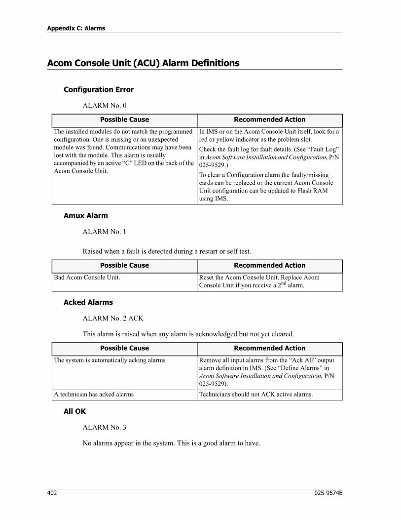
Appendix C: Alarms
402 025-9574E
Acom Console Unit (ACU) Alarm Definitions
Configuration Error
ALARM No. 0
Amux Alarm
ALARM No. 1
Raised when a fault is detected during a restart or self test.
Acked Alarms
ALARM No. 2 ACK
This alarm is raised when any alarm is acknowledged but not yet cleared.
All OK
ALARM No. 3
No alarms appear in the system. This is a good alarm to have.
Possible Cause Recommended Action
The installed modules do not match the programmed configuration. One is missing or an unexpected module was found. Communications may have been lost with the module. This alarm is usually accompanied by an active “C” LED on the back of the Acom Console Unit.
In IMS or on the Acom Console Unit itself, look for a red or yellow indicator as the problem slot.Check the fault log for fault details. (See “Fault Log” in Acom Software Installation and Configuration, P/N 025-9529.)To clear a Configuration alarm the faulty/missing cards can be replaced or the current Acom Console Unit configuration can be updated to Flash RAM using IMS.
Possible Cause Recommended Action
Bad Acom Console Unit. Reset the Acom Console Unit. Replace Acom Console Unit if you receive a 2nd alarm.
Possible Cause Recommended Action
The system is automatically acking alarms Remove all input alarms from the “Ack All” output alarm definition in IMS. (See “Define Alarms” in Acom Software Installation and Configuration, P/N 025-9529).
A technician has acked alarms Technicians should not ACK active alarms.
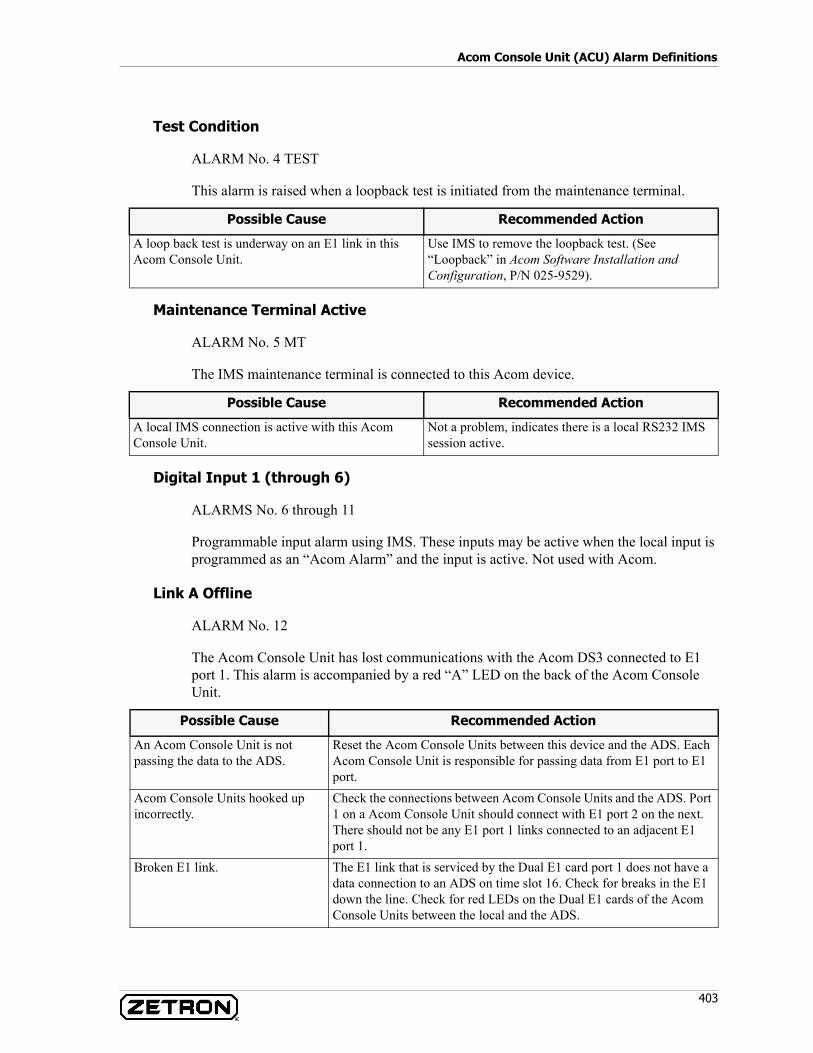
403
Acom Console Unit (ACU) Alarm Definitions
Test Condition
ALARM No. 4 TEST
This alarm is raised when a loopback test is initiated from the maintenance terminal.
Maintenance Terminal Active
ALARM No. 5 MT
The IMS maintenance terminal is connected to this Acom device.
Digital Input 1 (through 6)
ALARMS No. 6 through 11
Programmable input alarm using IMS. These inputs may be active when the local input is programmed as an “Acom Alarm” and the input is active. Not used with Acom.
Link A Offline
ALARM No. 12
The Acom Console Unit has lost communications with the Acom DS3 connected to E1 port 1. This alarm is accompanied by a red “A” LED on the back of the Acom Console Unit.
Possible Cause Recommended Action
A loop back test is underway on an E1 link in this Acom Console Unit.
Use IMS to remove the loopback test. (See “Loopback” in Acom Software Installation and Configuration, P/N 025-9529).
Possible Cause Recommended Action
A local IMS connection is active with this Acom Console Unit.
Not a problem, indicates there is a local RS232 IMS session active.
Possible Cause Recommended Action
An Acom Console Unit is not passing the data to the ADS.
Reset the Acom Console Units between this device and the ADS. Each Acom Console Unit is responsible for passing data from E1 port to E1 port.
Acom Console Units hooked up incorrectly.
Check the connections between Acom Console Units and the ADS. Port 1 on a Acom Console Unit should connect with E1 port 2 on the next. There should not be any E1 port 1 links connected to an adjacent E1 port 1.
Broken E1 link. The E1 link that is serviced by the Dual E1 card port 1 does not have a data connection to an ADS on time slot 16. Check for breaks in the E1 down the line. Check for red LEDs on the Dual E1 cards of the Acom Console Units between the local and the ADS.
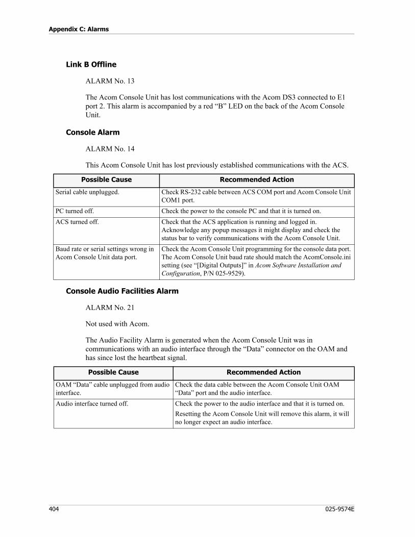
Appendix C: Alarms
404 025-9574E
Link B Offline
ALARM No. 13
The Acom Console Unit has lost communications with the Acom DS3 connected to E1 port 2. This alarm is accompanied by a red “B” LED on the back of the Acom Console Unit.
Console Alarm
ALARM No. 14
This Acom Console Unit has lost previously established communications with the ACS.
Console Audio Facilities Alarm
ALARM No. 21
Not used with Acom.
The Audio Facility Alarm is generated when the Acom Console Unit was in communications with an audio interface through the “Data” connector on the OAM and has since lost the heartbeat signal.
Possible Cause Recommended Action
Serial cable unplugged. Check RS-232 cable between ACS COM port and Acom Console Unit COM1 port.
PC turned off. Check the power to the console PC and that it is turned on.ACS turned off. Check that the ACS application is running and logged in.
Acknowledge any popup messages it might display and check the status bar to verify communications with the Acom Console Unit.
Baud rate or serial settings wrong in Acom Console Unit data port.
Check the Acom Console Unit programming for the console data port. The Acom Console Unit baud rate should match the AcomConsole.ini setting (see “[Digital Outputs]” in Acom Software Installation and Configuration, P/N 025-9529).
Possible Cause Recommended Action
OAM “Data” cable unplugged from audio interface.
Check the data cable between the Acom Console Unit OAM “Data” port and the audio interface.
Audio interface turned off. Check the power to the audio interface and that it is turned on.Resetting the Acom Console Unit will remove this alarm, it will no longer expect an audio interface.
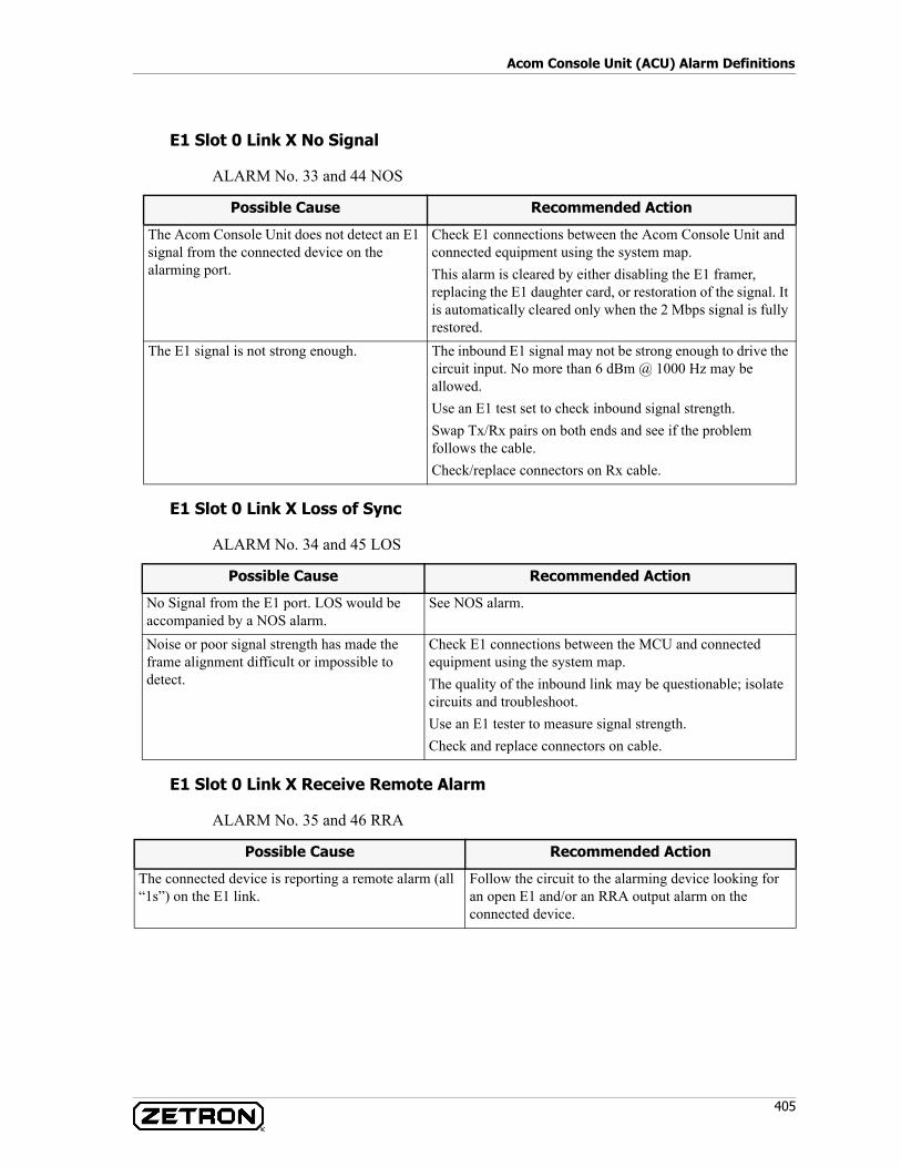
405
Acom Console Unit (ACU) Alarm Definitions
E1 Slot 0 Link X No Signal
ALARM No. 33 and 44 NOS
E1 Slot 0 Link X Loss of Sync
ALARM No. 34 and 45 LOS
E1 Slot 0 Link X Receive Remote Alarm
ALARM No. 35 and 46 RRA
Possible Cause Recommended Action
The Acom Console Unit does not detect an E1 signal from the connected device on the alarming port.
Check E1 connections between the Acom Console Unit and connected equipment using the system map.This alarm is cleared by either disabling the E1 framer, replacing the E1 daughter card, or restoration of the signal. It is automatically cleared only when the 2 Mbps signal is fully restored.
The E1 signal is not strong enough. The inbound E1 signal may not be strong enough to drive the circuit input. No more than 6 dBm @ 1000 Hz may be allowed.Use an E1 test set to check inbound signal strength.Swap Tx/Rx pairs on both ends and see if the problem follows the cable.Check/replace connectors on Rx cable.
Possible Cause Recommended Action
No Signal from the E1 port. LOS would be accompanied by a NOS alarm.
See NOS alarm.
Noise or poor signal strength has made the frame alignment difficult or impossible to detect.
Check E1 connections between the MCU and connected equipment using the system map.The quality of the inbound link may be questionable; isolate circuits and troubleshoot.Use an E1 tester to measure signal strength.Check and replace connectors on cable.
Possible Cause Recommended Action
The connected device is reporting a remote alarm (all “1s”) on the E1 link.
Follow the circuit to the alarming device looking for an open E1 and/or an RRA output alarm on the connected device.
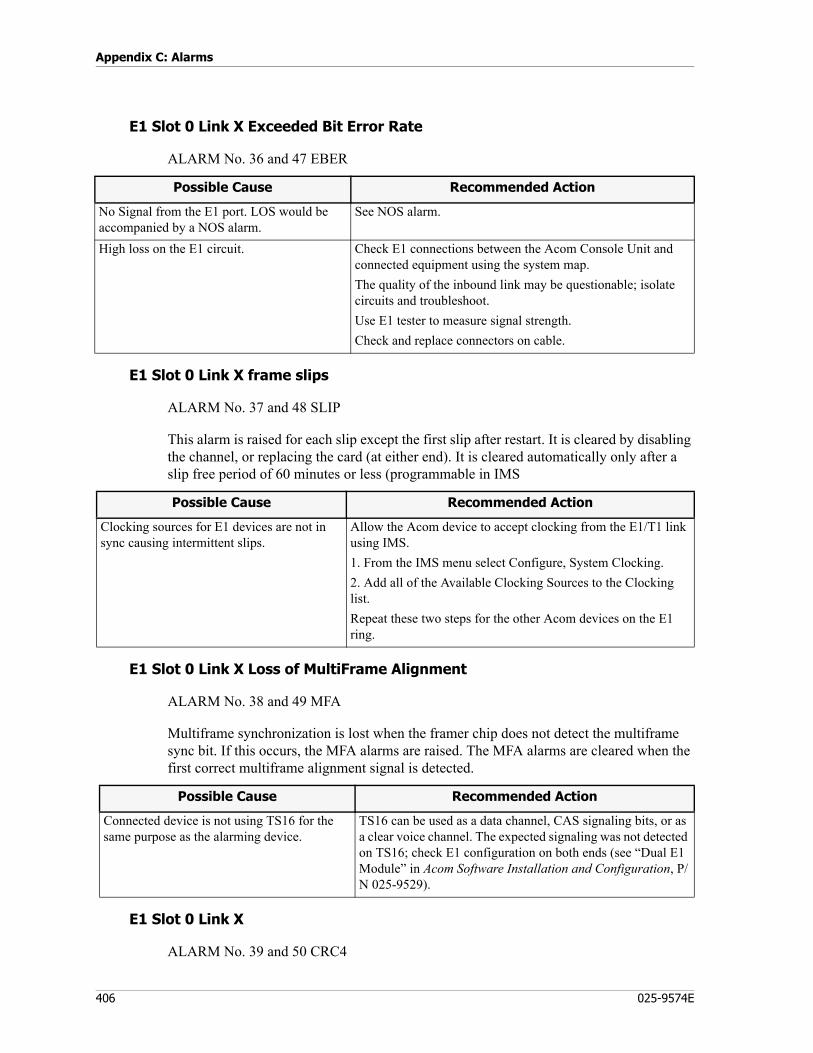
Appendix C: Alarms
406 025-9574E
E1 Slot 0 Link X Exceeded Bit Error Rate
ALARM No. 36 and 47 EBER
E1 Slot 0 Link X frame slips
ALARM No. 37 and 48 SLIP
This alarm is raised for each slip except the first slip after restart. It is cleared by disabling the channel, or replacing the card (at either end). It is cleared automatically only after a slip free period of 60 minutes or less (programmable in IMS
E1 Slot 0 Link X Loss of MultiFrame Alignment
ALARM No. 38 and 49 MFA
Multiframe synchronization is lost when the framer chip does not detect the multiframe sync bit. If this occurs, the MFA alarms are raised. The MFA alarms are cleared when the first correct multiframe alignment signal is detected.
E1 Slot 0 Link X
ALARM No. 39 and 50 CRC4
Possible Cause Recommended Action
No Signal from the E1 port. LOS would be accompanied by a NOS alarm.
See NOS alarm.
High loss on the E1 circuit. Check E1 connections between the Acom Console Unit and connected equipment using the system map.The quality of the inbound link may be questionable; isolate circuits and troubleshoot.Use E1 tester to measure signal strength.Check and replace connectors on cable.
Possible Cause Recommended Action
Clocking sources for E1 devices are not in sync causing intermittent slips.
Allow the Acom device to accept clocking from the E1/T1 link using IMS. 1. From the IMS menu select Configure, System Clocking.2. Add all of the Available Clocking Sources to the Clocking list.Repeat these two steps for the other Acom devices on the E1 ring.
Possible Cause Recommended Action
Connected device is not using TS16 for the same purpose as the alarming device.
TS16 can be used as a data channel, CAS signaling bits, or as a clear voice channel. The expected signaling was not detected on TS16; check E1 configuration on both ends (see “Dual E1 Module” in Acom Software Installation and Configuration, P/N 025-9529).
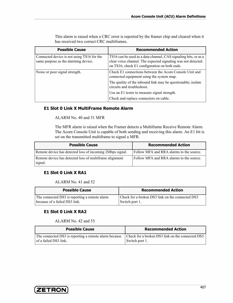
407
Acom Console Unit (ACU) Alarm Definitions
This alarm is raised when a CRC error is reported by the framer chip and cleared when it has received two correct CRC multiframes.
E1 Slot 0 Link X MultiFrame Remote Alarm
ALARM No. 40 and 51 MFR
The MFR alarm is raised when the Framer detects a Multiframe Receive Remote Alarm. The Acom Console Unit is capable of both sending and receiving this alarm. An E1 bit is set on the transmitted multiframe to signal a MFR.
E1 Slot 0 Link X RA1
ALARM No. 41 and 52
E1 Slot 0 Link X RA2
ALARM No. 42 and 53
Possible Cause Recommended Action
Connected device is not using TS16 for the same purpose as the alarming device.
TS16 can be used as a data channel, CAS signaling bits, or as a clear voice channel. The expected signaling was not detected on TS16, check E1 configuration on both ends.
Noise or poor signal strength. Check E1 connections between the Acom Console Unit and connected equipment using the system map.The quality of the inbound link may be questionable; isolate circuits and troubleshoot.Use an E1 tester to measure signal strength.Check and replace connectors on cable.
Possible Cause Recommended Action
Remote device has detected loss of incoming 2Mbps signal. Follow MFA and RRA alarms to the source.Remote device has detected loss of multiframe alignment signal.
Follow MFA and RRA alarms to the source.
Possible Cause Recommended Action
The connected DS3 is reporting a remote alarm because of a failed DS3 link.
Check for a broken DS3 link on the connected DS3 Switch port 1.
Possible Cause Recommended Action
The connected DS3 is reporting a remote alarm because of a failed DS3 link.
Check for a broken DS3 link on the connected DS3 Switch port 1.
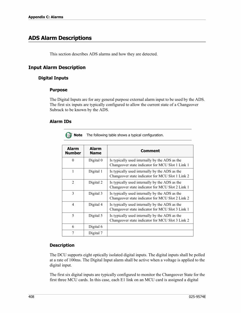
Appendix C: Alarms
408 025-9574E
ADS Alarm Descriptions
This section describes ADS alarms and how they are detected.
Input Alarm Description
Digital Inputs
Purpose
The Digital Inputs are for any general purpose external alarm input to be used by the ADS. The first six inputs are typically configured to allow the current state of a Changeover Subrack to be known by the ADS.
Alarm IDs
Description
The DCU supports eight optically isolated digital inputs. The digital inputs shall be polled at a rate of 100ms. The Digital Input alarm shall be active when a voltage is applied to the digital input.
The first six digital inputs are typically configured to monitor the Changeover State for the first three MCU cards. In this case, each E1 link on an MCU card is assigned a digital
Note The following table shows a typical configuration.
Alarm Number
Alarm Name Comment
0 Digital 0 Is typically used internally by the ADS as the Changeover state indicator for MCU Slot 1 Link 1
1 Digital 1 Is typically used internally by the ADS as the Changeover state indicator for MCU Slot 1 Link 2
2 Digital 2 Is typically used internally by the ADS as the Changeover state indicator for MCU Slot 2 Link 1
3 Digital 3 Is typically used internally by the ADS as the Changeover state indicator for MCU Slot 2 Link 2
4 Digital 4 Is typically used internally by the ADS as the Changeover state indicator for MCU Slot 3 Link 1
5 Digital 5 Is typically used internally by the ADS as the Changeover state indicator for MCU Slot 3 Link 2
6 Digital 67 Digital 7
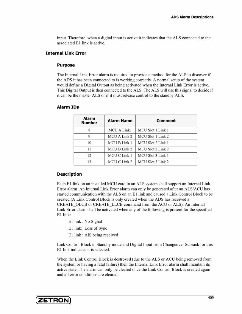
409
ADS Alarm Descriptions
input. Therefore, when a digital input is active it indicates that the ALS connected to the associated E1 link is active.
Internal Link Error
Purpose
The Internal Link Error alarm is required to provide a method for the ALS to discover if the ADS it has been connected to is working correctly. A normal setup of the system would define a Digital Output as being activated when the Internal Link Error is active. This Digital Output is then connected to the ALS. The ALS will use this signal to decide if it can be the master ALS or if it must release control to the standby ALS.
Alarm IDs
Description
Each E1 link on an installed MCU card in an ALS system shall support an Internal Link Error alarm. An Internal Link Error alarm can only be generated after an ALS/ACU has started communication with the ALS on an E1 link and caused a Link Control Block to be created (A Link Control Block is only created when the ADS has received a CREATE_OLCB or CREATE_LLCB command from the ACU or ALS). An Internal Link Error alarm shall be activated when any of the following is present for the specified E1 link:
E1 link : No SignalE1 link: Loss of SyncE1 link : AIS being received
Link Control Block in Standby mode and Digital Input from Changeover Subrack for this E1 link indicates it is selected.
When the Link Control Block is destroyed (due to the ALS or ACU being removed from the system or having a fatal failure) then the Internal Link Error alarm shall maintain its active state. The alarm can only be cleared once the Link Control Block is created again and all error conditions are cleared.
Alarm Number Alarm Name Comment
8 MCU A Link1 MCU Slot 1 Link 19 MCU A Link 2 MCU Slot 1 Link 2
10 MCU B Link 1 MCU Slot 2 Link 111 MCU B Link 2 MCU Slot 2 Link 212 MCU C Link 1 MCU Slot 3 Link 113 MCU C Link 2 MCU Slot 3 Link 2
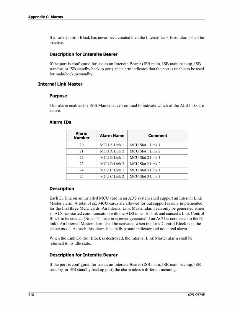
Appendix C: Alarms
410 025-9574E
If a Link Control Block has never been created then the Internal Link Error alarm shall be inactive.
Description for Intersite Bearer
If the port is configured for use as an Intersite Bearer (ISB main, ISB main backup, ISB standby, or ISB standby backup port), the alarm indicates that the port is unable to be used for main/backup/standby.
Internal Link Master
Purpose
This alarm enables the IMS Maintenance Terminal to indicate which of the ALS links are active.
Alarm IDs
Description
Each E1 link on an installed MCU card in an ADS system shall support an Internal Link Master alarm. A total of six MCU cards are allowed for but support is only implemented for the first three MCU cards. An Internal Link Master alarm can only be generated when an ALS has started communication with the ADS on an E1 link and caused a Link Control Block to be created (Note: This alarm is never generated if an ACU is connected to the E1 link). An Internal Master alarm shall be activated when the Link Control Block is in the active mode. As such this alarm is actually a state indicator and not a real alarm.
When the Link Control Block is destroyed, the Internal Link Master alarm shall be returned to its idle state.
Description for Intersite Bearer
If the port is configured for use as an Intersite Bearer (ISB main, ISB main backup, ISB standby, or ISB standby backup port) the alarm takes a different meaning.
Alarm Number Alarm Name Comment
20 MCU A Link 1 MCU Slot 1 Link 121 MCU A Link 2 MCU Slot 1 Link 222 MCU B Link 1 MCU Slot 2 Link 123 MCU B Link 2 MCU Slot 2 Link 224 MCU C Link 1 MCU Slot 3 Link 125 MCU C Link 2 MCU Slot 3 Link 2
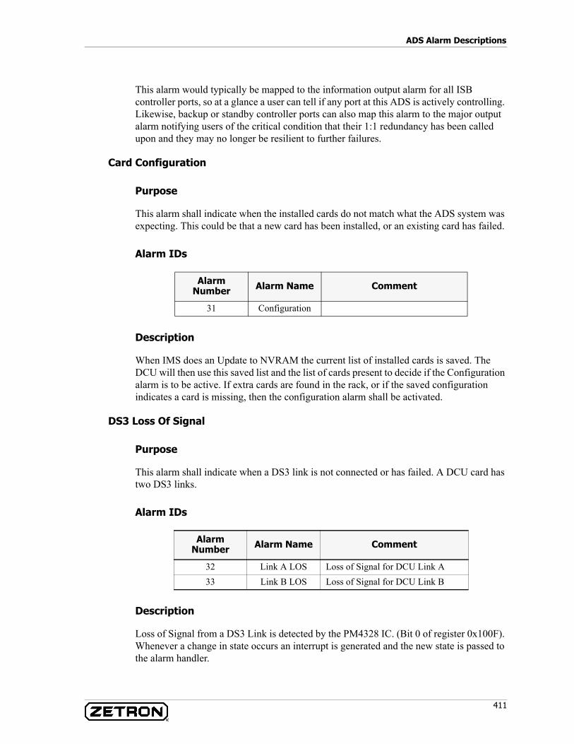
411
ADS Alarm Descriptions
This alarm would typically be mapped to the information output alarm for all ISB controller ports, so at a glance a user can tell if any port at this ADS is actively controlling. Likewise, backup or standby controller ports can also map this alarm to the major output alarm notifying users of the critical condition that their 1:1 redundancy has been called upon and they may no longer be resilient to further failures.
Card Configuration
Purpose
This alarm shall indicate when the installed cards do not match what the ADS system was expecting. This could be that a new card has been installed, or an existing card has failed.
Alarm IDs
Description
When IMS does an Update to NVRAM the current list of installed cards is saved. The DCU will then use this saved list and the list of cards present to decide if the Configuration alarm is to be active. If extra cards are found in the rack, or if the saved configuration indicates a card is missing, then the configuration alarm shall be activated.
DS3 Loss Of Signal
Purpose
This alarm shall indicate when a DS3 link is not connected or has failed. A DCU card has two DS3 links.
Alarm IDs
Description
Loss of Signal from a DS3 Link is detected by the PM4328 IC. (Bit 0 of register 0x100F). Whenever a change in state occurs an interrupt is generated and the new state is passed to the alarm handler.
Alarm Number Alarm Name Comment
31 Configuration
Alarm Number Alarm Name Comment
32 Link A LOS Loss of Signal for DCU Link A33 Link B LOS Loss of Signal for DCU Link B
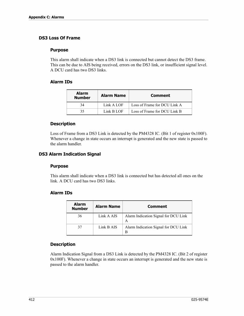
Appendix C: Alarms
412 025-9574E
DS3 Loss Of Frame
Purpose
This alarm shall indicate when a DS3 link is connected but cannot detect the DS3 frame. This can be due to AIS being received, errors on the DS3 link, or insufficient signal level. A DCU card has two DS3 links.
Alarm IDs
Description
Loss of Frame from a DS3 Link is detected by the PM4328 IC. (Bit 1 of register 0x100F). Whenever a change in state occurs an interrupt is generated and the new state is passed to the alarm handler.
DS3 Alarm Indication Signal
Purpose
This alarm shall indicate when a DS3 link is connected but has detected all ones on the link. A DCU card has two DS3 links.
Alarm IDs
Description
Alarm Indication Signal from a DS3 Link is detected by the PM4328 IC. (Bit 2 of register 0x100F). Whenever a change in state occurs an interrupt is generated and the new state is passed to the alarm handler.
Alarm Number Alarm Name Comment
34 Link A LOF Loss of Frame for DCU Link A35 Link B LOF Loss of Frame for DCU Link B
Alarm Number Alarm Name Comment
36 Link A AIS Alarm Indication Signal for DCU Link A
37 Link B AIS Alarm Indication Signal for DCU Link B

413
ADS Alarm Descriptions
DS3 Link Failure
Purpose
This alarm shall indicate when a DS3 link is unable to be used to pass audio/data around the ADS ring.
Alarm IDs
Description
The Link Failed alarm is made active whenever the DCU discovers that it cannot use the link to talk to the adjacent racks. This alarm shall be set when any of the following conditions are present:
• DS3 Loss Of Signal• DS3 Loss Of Frame• DS3 Alarm Indication Signal• Failure of C-Bit messaging to talk to adjacent rack• Lockup of adjacent rack
DS3 Link Wrapped
Purpose
This alarm shall indicate when a DS3 link has been placed into the wrapped mode. Wrapped mode is used to cause all data and audio to go around the ring in the opposite direction and hence skip the broken link.
Alarm IDs
Alarm Number Alarm Name Comment
38 Link A Failed Link A not usable39 Link B Failed Link B not usable
Alarm Number Alarm Name Comment
40 Link A Wrapped Link A is wrapped41 Link B Wrapped Link B is wrapped
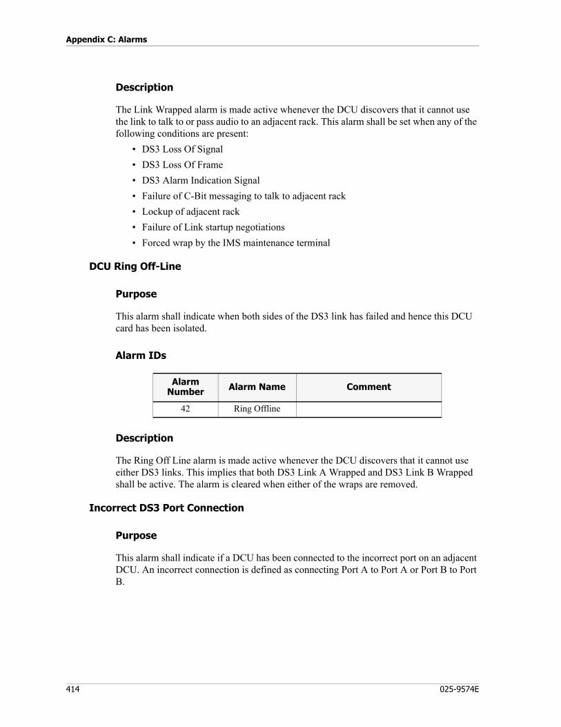
Appendix C: Alarms
414 025-9574E
Description
The Link Wrapped alarm is made active whenever the DCU discovers that it cannot use the link to talk to or pass audio to an adjacent rack. This alarm shall be set when any of the following conditions are present:
• DS3 Loss Of Signal• DS3 Loss Of Frame• DS3 Alarm Indication Signal• Failure of C-Bit messaging to talk to adjacent rack• Lockup of adjacent rack• Failure of Link startup negotiations• Forced wrap by the IMS maintenance terminal
DCU Ring Off-Line
Purpose
This alarm shall indicate when both sides of the DS3 link has failed and hence this DCU card has been isolated.
Alarm IDs
Description
The Ring Off Line alarm is made active whenever the DCU discovers that it cannot use either DS3 links. This implies that both DS3 Link A Wrapped and DS3 Link B Wrapped shall be active. The alarm is cleared when either of the wraps are removed.
Incorrect DS3 Port Connection
Purpose
This alarm shall indicate if a DCU has been connected to the incorrect port on an adjacent DCU. An incorrect connection is defined as connecting Port A to Port A or Port B to Port B.
Alarm Number Alarm Name Comment
42 Ring Offline
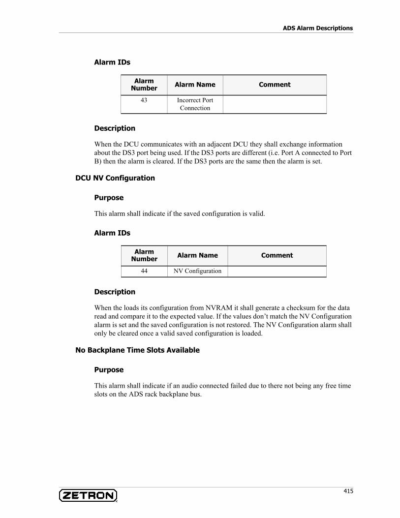
415
ADS Alarm Descriptions
Alarm IDs
Description
When the DCU communicates with an adjacent DCU they shall exchange information about the DS3 port being used. If the DS3 ports are different (i.e. Port A connected to Port B) then the alarm is cleared. If the DS3 ports are the same then the alarm is set.
DCU NV Configuration
Purpose
This alarm shall indicate if the saved configuration is valid.
Alarm IDs
Description
When the loads its configuration from NVRAM it shall generate a checksum for the data read and compare it to the expected value. If the values don’t match the NV Configuration alarm is set and the saved configuration is not restored. The NV Configuration alarm shall only be cleared once a valid saved configuration is loaded.
No Backplane Time Slots Available
Purpose
This alarm shall indicate if an audio connected failed due to there not being any free time slots on the ADS rack backplane bus.
Alarm Number Alarm Name Comment
43 Incorrect Port Connection
Alarm Number Alarm Name Comment
44 NV Configuration
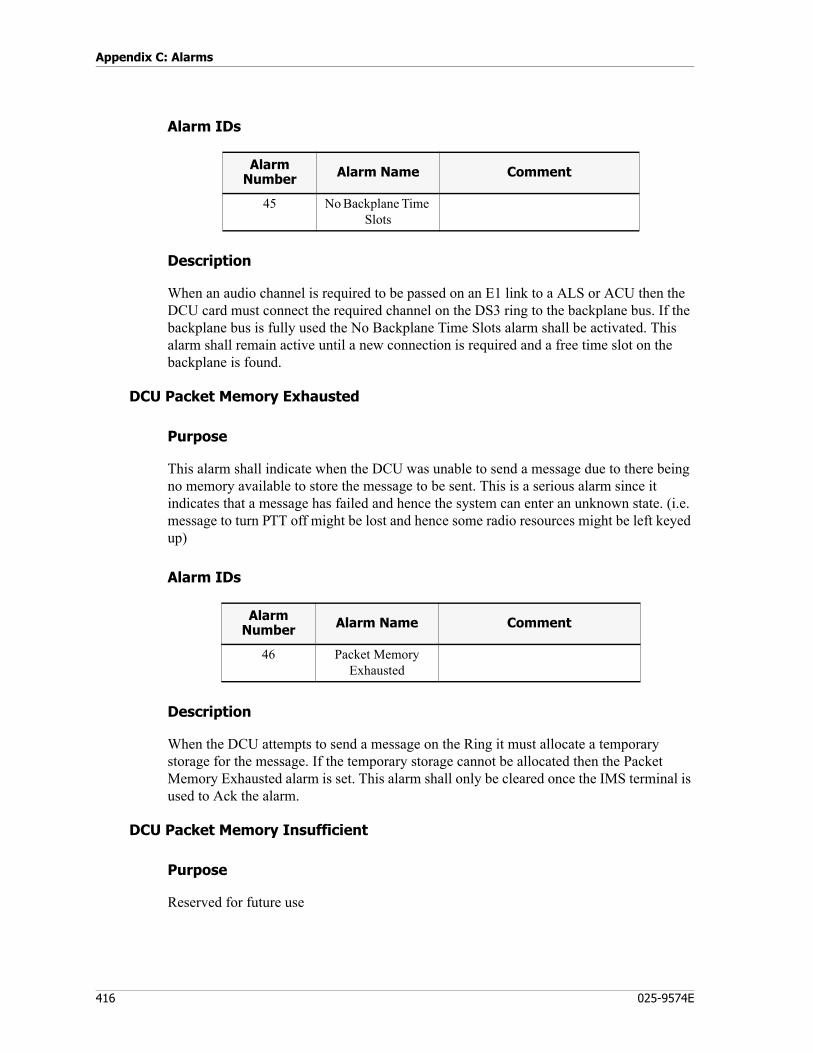
Appendix C: Alarms
416 025-9574E
Alarm IDs
Description
When an audio channel is required to be passed on an E1 link to a ALS or ACU then the DCU card must connect the required channel on the DS3 ring to the backplane bus. If the backplane bus is fully used the No Backplane Time Slots alarm shall be activated. This alarm shall remain active until a new connection is required and a free time slot on the backplane is found.
DCU Packet Memory Exhausted
Purpose
This alarm shall indicate when the DCU was unable to send a message due to there being no memory available to store the message to be sent. This is a serious alarm since it indicates that a message has failed and hence the system can enter an unknown state. (i.e. message to turn PTT off might be lost and hence some radio resources might be left keyed up)
Alarm IDs
Description
When the DCU attempts to send a message on the Ring it must allocate a temporary storage for the message. If the temporary storage cannot be allocated then the Packet Memory Exhausted alarm is set. This alarm shall only be cleared once the IMS terminal is used to Ack the alarm.
DCU Packet Memory Insufficient
Purpose
Reserved for future use
Alarm Number Alarm Name Comment
45 No Backplane Time Slots
Alarm Number Alarm Name Comment
46 Packet Memory Exhausted
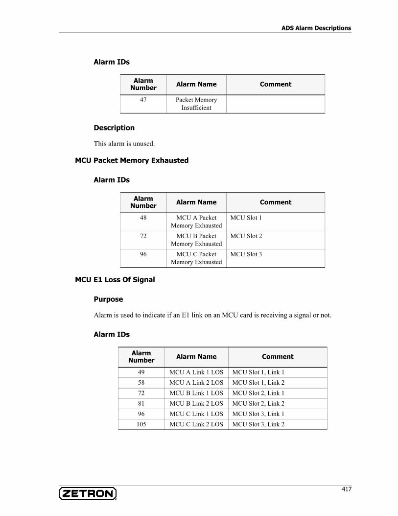
417
ADS Alarm Descriptions
Alarm IDs
Description
This alarm is unused.
MCU Packet Memory Exhausted
Alarm IDs
MCU E1 Loss Of Signal
Purpose
Alarm is used to indicate if an E1 link on an MCU card is receiving a signal or not.
Alarm IDs
Alarm Number Alarm Name Comment
47 Packet Memory Insufficient
Alarm Number Alarm Name Comment
48 MCU A Packet Memory Exhausted
MCU Slot 1
72 MCU B Packet Memory Exhausted
MCU Slot 2
96 MCU C Packet Memory Exhausted
MCU Slot 3
Alarm Number Alarm Name Comment
49 MCU A Link 1 LOS MCU Slot 1, Link 158 MCU A Link 2 LOS MCU Slot 1, Link 272 MCU B Link 1 LOS MCU Slot 2, Link 181 MCU B Link 2 LOS MCU Slot 2, Link 296 MCU C Link 1 LOS MCU Slot 3, Link 1105 MCU C Link 2 LOS MCU Slot 3, Link 2
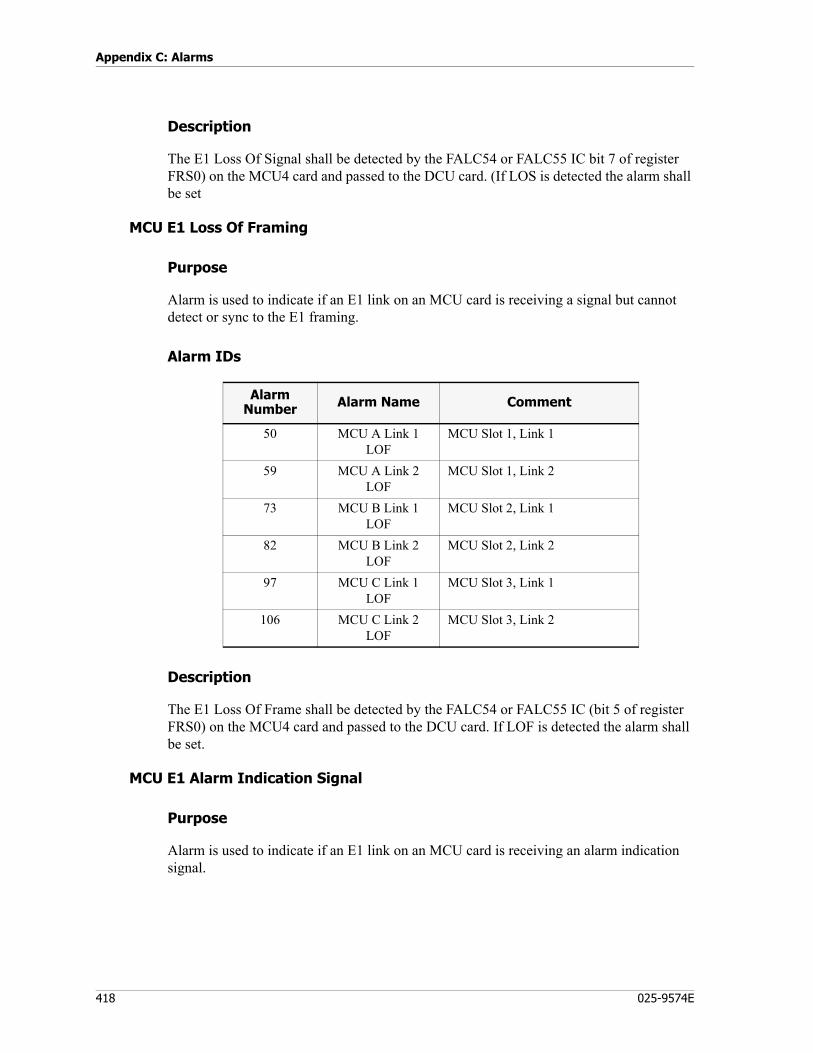
Appendix C: Alarms
418 025-9574E
Description
The E1 Loss Of Signal shall be detected by the FALC54 or FALC55 IC bit 7 of register FRS0) on the MCU4 card and passed to the DCU card. (If LOS is detected the alarm shall be set
MCU E1 Loss Of Framing
Purpose
Alarm is used to indicate if an E1 link on an MCU card is receiving a signal but cannot detect or sync to the E1 framing.
Alarm IDs
Description
The E1 Loss Of Frame shall be detected by the FALC54 or FALC55 IC (bit 5 of register FRS0) on the MCU4 card and passed to the DCU card. If LOF is detected the alarm shall be set.
MCU E1 Alarm Indication Signal
Purpose
Alarm is used to indicate if an E1 link on an MCU card is receiving an alarm indication signal.
Alarm Number Alarm Name Comment
50 MCU A Link 1 LOF
MCU Slot 1, Link 1
59 MCU A Link 2 LOF
MCU Slot 1, Link 2
73 MCU B Link 1 LOF
MCU Slot 2, Link 1
82 MCU B Link 2 LOF
MCU Slot 2, Link 2
97 MCU C Link 1 LOF
MCU Slot 3, Link 1
106 MCU C Link 2 LOF
MCU Slot 3, Link 2
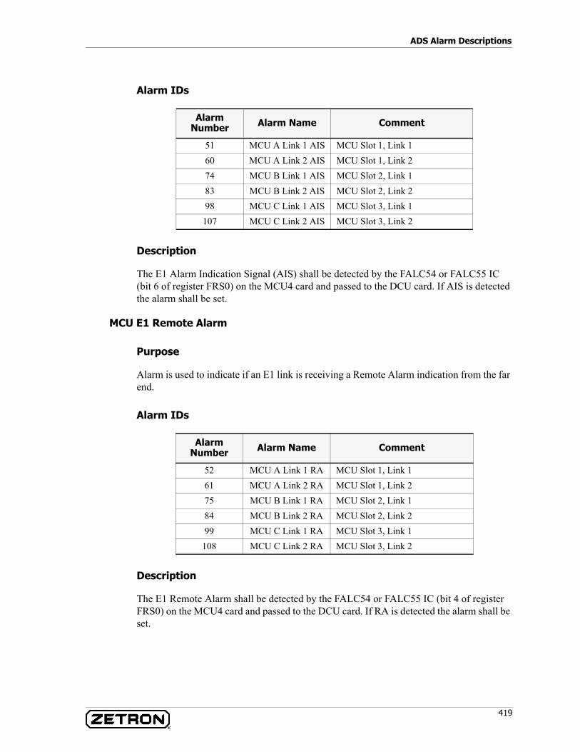
419
ADS Alarm Descriptions
Alarm IDs
Description
The E1 Alarm Indication Signal (AIS) shall be detected by the FALC54 or FALC55 IC (bit 6 of register FRS0) on the MCU4 card and passed to the DCU card. If AIS is detected the alarm shall be set.
MCU E1 Remote Alarm
Purpose
Alarm is used to indicate if an E1 link is receiving a Remote Alarm indication from the far end.
Alarm IDs
Description
The E1 Remote Alarm shall be detected by the FALC54 or FALC55 IC (bit 4 of register FRS0) on the MCU4 card and passed to the DCU card. If RA is detected the alarm shall be set.
Alarm Number Alarm Name Comment
51 MCU A Link 1 AIS MCU Slot 1, Link 160 MCU A Link 2 AIS MCU Slot 1, Link 274 MCU B Link 1 AIS MCU Slot 2, Link 183 MCU B Link 2 AIS MCU Slot 2, Link 298 MCU C Link 1 AIS MCU Slot 3, Link 1
107 MCU C Link 2 AIS MCU Slot 3, Link 2
Alarm Number Alarm Name Comment
52 MCU A Link 1 RA MCU Slot 1, Link 161 MCU A Link 2 RA MCU Slot 1, Link 275 MCU B Link 1 RA MCU Slot 2, Link 184 MCU B Link 2 RA MCU Slot 2, Link 299 MCU C Link 1 RA MCU Slot 3, Link 1
108 MCU C Link 2 RA MCU Slot 3, Link 2

Appendix C: Alarms
420 025-9574E
MCU E1 Remote Alarm 1
Purpose
Alarm is used to indicate if the CCS signaling on an E1 link is receiving a Remote Alarm 1.
Remote Alarm 1 is defined as bit 2 of the CCS stream for time slot 16.
Alarm IDs
Description
The E1 Remote Alarm 1 shall be detected by the DCU card. When the ALS or ACU activates its Remote Alarm 1 output a CCS message for time slot 16 is sent. This is passed by the MCU4 card to the DCU card. The DCU card shall then check if the CCS message was for time slot 16 and if so shall test bit 2. If bit 2 is a 0 the alarm shall be made active.
MCU E1 Remote Alarm 2
Purpose
Alarm is used to indicate if the CCS signaling on an E1 link is receiving a Remote Alarm 2.
Remote Alarm 3 is defined as bit 2 of the CCS stream for time slot 16.
Alarm Number Alarm Name Comment
53 MCU A Link 1 RA1 MCU Slot 1, Link 162 MCU A Link 2 RA1 MCU Slot 1, Link 276 MCU B Link 1 RA1 MCU Slot 2, Link 185 MCU B Link 2 RA1 MCU Slot 2, Link 2
100 MCU C Link 1 RA1 MCU Slot 3, Link 1109 MCU C Link 2 RA1 MCU Slot 3, Link 2
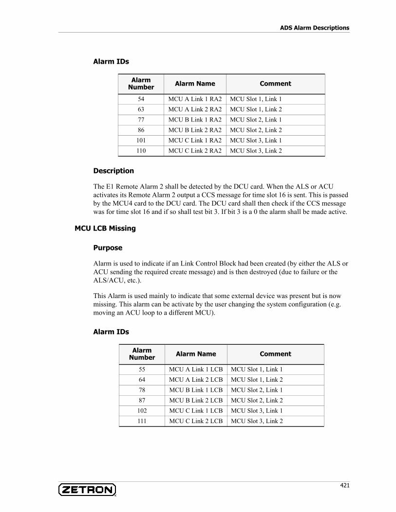
421
ADS Alarm Descriptions
Alarm IDs
Description
The E1 Remote Alarm 2 shall be detected by the DCU card. When the ALS or ACU activates its Remote Alarm 2 output a CCS message for time slot 16 is sent. This is passed by the MCU4 card to the DCU card. The DCU card shall then check if the CCS message was for time slot 16 and if so shall test bit 3. If bit 3 is a 0 the alarm shall be made active.
MCU LCB Missing
Purpose
Alarm is used to indicate if an Link Control Block had been created (by either the ALS or ACU sending the required create message) and is then destroyed (due to failure or the ALS/ACU, etc.).
This Alarm is used mainly to indicate that some external device was present but is now missing. This alarm can be activate by the user changing the system configuration (e.g. moving an ACU loop to a different MCU).
Alarm IDs
Alarm Number Alarm Name Comment
54 MCU A Link 1 RA2 MCU Slot 1, Link 163 MCU A Link 2 RA2 MCU Slot 1, Link 277 MCU B Link 1 RA2 MCU Slot 2, Link 186 MCU B Link 2 RA2 MCU Slot 2, Link 2
101 MCU C Link 1 RA2 MCU Slot 3, Link 1110 MCU C Link 2 RA2 MCU Slot 3, Link 2
Alarm Number Alarm Name Comment
55 MCU A Link 1 LCB MCU Slot 1, Link 164 MCU A Link 2 LCB MCU Slot 1, Link 278 MCU B Link 1 LCB MCU Slot 2, Link 187 MCU B Link 2 LCB MCU Slot 2, Link 2
102 MCU C Link 1 LCB MCU Slot 3, Link 1111 MCU C Link 2 LCB MCU Slot 3, Link 2
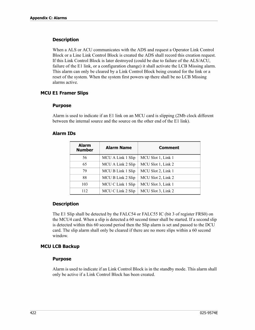
Appendix C: Alarms
422 025-9574E
Description
When a ALS or ACU communicates with the ADS and request a Operator Link Control Block or a Line Link Control Block is created the ADS shall record this creation request. If this Link Control Block is later destroyed (could be due to failure of the ALS/ACU, failure of the E1 link, or a configuration change) it shall activate the LCB Missing alarm. This alarm can only be cleared by a Link Control Block being created for the link or a reset of the system. When the system first powers up there shall be no LCB Missing alarms active.
MCU E1 Framer Slips
Purpose
Alarm is used to indicate if an E1 link on an MCU card is slipping (2Mb clock different between the internal source and the source on the other end of the E1 link).
Alarm IDs
Description
The E1 Slip shall be detected by the FALC54 or FALC55 IC (bit 3 of register FRS0) on the MCU4 card. When a slip is detected a 60 second timer shall be started. If a second slip is detected within this 60 second period then the Slip alarm is set and passed to the DCU card. The slip alarm shall only be cleared if there are no more slips within a 60 second window.
MCU LCB Backup
Purpose
Alarm is used to indicate if an Link Control Block is in the standby mode. This alarm shall only be active if a Link Control Block has been created.
Alarm Number Alarm Name Comment
56 MCU A Link 1 Slip MCU Slot 1, Link 165 MCU A Link 2 Slip MCU Slot 1, Link 279 MCU B Link 1 Slip MCU Slot 2, Link 188 MCU B Link 2 Slip MCU Slot 2, Link 2103 MCU C Link 1 Slip MCU Slot 3, Link 1112 MCU C Link 2 Slip MCU Slot 3, Link 2
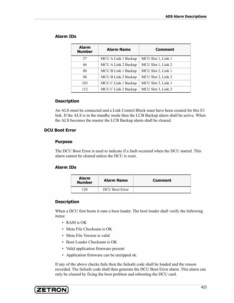
423
ADS Alarm Descriptions
Alarm IDs
Description
An ALS must be connected and a Link Control Block must have been created for this E1 link. If the ALS is in the standby mode then the LCB Backup alarm shall be active. When the ALS becomes the master the LCB Backup alarm shall be cleared.
DCU Boot Error
Purpose
The DCU Boot Error is used to indicate if a fault occurred when the DCU started. This alarm cannot be cleared unless the DCU is reset.
Alarm IDs
Description
When a DCU first boots it runs a boot loader. The boot loader shall verify the following items:
• RAM is OK• Meta File Checksum is OK• Meta File Version is valid• Boot Loader Checksum is OK• Valid application firmware present• Application firmware can be unzipped ok.
If any of the above checks fails then the failsafe code shall be loaded and the reason recorded. The failsafe code shall then generate the DCU Boot Error alarm. This alarm can only be cleared by fixing the boot problem and rebooting the DCU card.
Alarm Number Alarm Name Comment
57 MCU A Link 1 Backup MCU Slot 1, Link 166 MCU A Link 2 Backup MCU Slot 1, Link 280 MCU B Link 1 Backup MCU Slot 2, Link 188 MCU B Link 2 Backup MCU Slot 2, Link 2
103 MCU C Link 1 Backup MCU Slot 3, Link 1112 MCU C Link 2 Backup MCU Slot 3, Link 2
Alarm Number Alarm Name Comment
120 DCU Boot Error
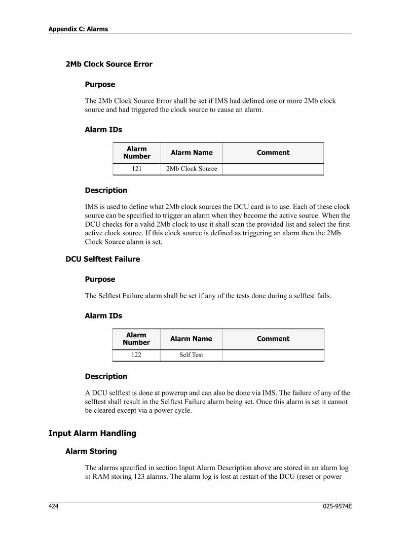
Appendix C: Alarms
424 025-9574E
2Mb Clock Source Error
Purpose
The 2Mb Clock Source Error shall be set if IMS had defined one or more 2Mb clock source and had triggered the clock source to cause an alarm.
Alarm IDs
Description
IMS is used to define what 2Mb clock sources the DCU card is to use. Each of these clock source can be specified to trigger an alarm when they become the active source. When the DCU checks for a valid 2Mb clock to use it shall scan the provided list and select the first active clock source. If this clock source is defined as triggering an alarm then the 2Mb Clock Source alarm is set.
DCU Selftest Failure
Purpose
The Selftest Failure alarm shall be set if any of the tests done during a selftest fails.
Alarm IDs
Description
A DCU selftest is done at powerup and can also be done via IMS. The failure of any of the selftest shall result in the Selftest Failure alarm being set. Once this alarm is set it cannot be cleared except via a power cycle.
Input Alarm Handling
Alarm Storing
The alarms specified in section Input Alarm Description above are stored in an alarm log in RAM storing 123 alarms. The alarm log is lost at restart of the DCU (reset or power
Alarm Number Alarm Name Comment
121 2Mb Clock Source
Alarm Number Alarm Name Comment
122 Self Test
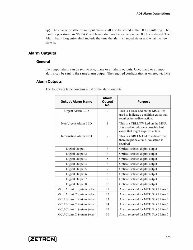
425
ADS Alarm Descriptions
up). The change of state of an input alarm shall also be stored in the DCU Fault Log. The Fault Log is stored in NVRAM and hence shall not be lost when the DCU is restarted. The Alarm Fault Log entry shall include the time the alarm changed states and what the new state is.
Alarm Outputs
General
Each input alarm can be sent to one, many or all alarm outputs. One, many or all input alarms can be sent to the same alarm output. The required configuration is entered via IMS
Alarm Outputs
The following table contains a list of the alarm outputs.
Output Alarm NameAlarm Output
No.Purpose
Urgent Alarm LED 0 This is a RED Led on the MSU. It is used to indicate a condition exists that requires immediate action.
Non Urgent Alarm LED 1 This is a YELLOW Led on the MSU. It is used to indicate a possible fault exists that might required action
Information Alarm LED 2 This is a GREEN Led to indicate that there might be a fault. No action is required.
Digital Output 1 3 Optical Isolated digital outputDigital Output 2 4 Optical Isolated digital outputDigital Output 3 5 Optical Isolated digital outputDigital Output 4 6 Optical Isolated digital outputDigital Output 5 7 Optical Isolated digital outputDigital Output 6 8 Optical Isolated digital outputDigital Output 7 9 Optical Isolated digital outputDigital Output 8 10 Optical Isolated digital output
MCU A Link 1 System Select 11 Alarm reserved for MCU Slot 1 Link 1MCU A Link 2 System Select 12 Alarm reserved for MCU Slot 1 Link 2MCU B Link 1 System Select 13 Alarm reserved for MCU Slot 2 Link 1MCU B Link 2 System Select 14 Alarm reserved for MCU Slot 2 Link 2MCU C Link 1 System Select 15 Alarm reserved for MCU Slot 3 Link 1MCU C Link 2 System Select 16 Alarm reserved for MCU Slot 3 Link 2
Appendix C: Alarms
426 025-9574E
Output Alarm Operating Modes
An output alarm can be set to be in one of three operating modes:1. Passive Mode
In passive mode the alarm output becomes active when an alarm input becomes active and is de-activated only when it is acknowledged from IMS. This is the default operating mode for alarm outputs.
2. Locked ModeIn locked mode the alarm output becomes active when an alarm input becomes active. It can only be de-activated when acknowledged from IMS. The alarm input becoming de-activated does not put the alarm output into the idle state. (In this mode a brief failure, such a temporary link failure is latched until the alarm is acknowledged.)
3. Pulsed ModeIn pulsed mode the alarm output will become active when an alarm input becomes active. The output will stay active for a set time and then become de-activated. The active pulse time is set from IMS and is common for all pulsed outputs.Before the output can become active again the alarm input has to be de-activated or the alarm acknowledged.
Supervisor Alarms in IMS
Supervisor alarms are designed to alert a supervisor that there is a problem with the console system.
Supervisor Console Alarms
Output alarms will cause the on-screen ALARM button to flash red and an audible sound to be played to the supervisor. This functionality was designed to alert supervisors that there is an alarm condition within the system so that he/she may take appropriate action in a timely fashion. Note that some alarms are easily resolved by the supervisor without calling in the system maintenance technician. In order to see alarm indications at an operator console position you must use the login type “SUPERVISOR” and you must have the desired alarm strings defined in the “AcomConsole.ini” file. Alarm strings are defined in the “AcomConsole.ini” file under the [ALARMS] section. Note that if an alarm is not defined then it will not be displayed on the supervisor’s console. There are four types of alarms that can be defined and displayed at the supervisor position. These alarm types include NAME, ACU, CONSOLE, and DEVICE alarms (ACU is Acom Console Unit). These alarms are generated by various system components and are passed around the system via time slot 16 of the E1 console loops.
If the Alarm button exists on the Acom Console Software screen, the device alarms will be reported regardless if you are logged in as Supervisor or any other operator type.
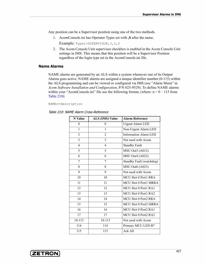
427
Supervisor Alarms in IMS
Any position can be a Supervisor position using one of the two methods.1. AcomConsole.ini has Operator Types set with ,S after the name.
Example: Type1=SUPERVISOR,3,3,S2. The Acom Console Unit supervisor checkbox is enabled in the Acom Console Unit
settings in IMS. This means that this position will be a Supervisor Position regardless of the login type set in the AcomConsole.ini file.
Name Alarms
NAME alarms are generated by an ALS within a system whenever one of its Output Alarms goes active. NAME alarms are assigned a unique identifier number (0-115) within the ALS programming and can be viewed or configured via IMS (see “Alarm Menu” in Acom Software Installation and Configuration, P/N 025-9529). To define NAME alarms within your “AcomConsole.ini” file use the following format, (where: n = 0 – 115 from Table 210):
NAMEn=description
Table 210: NAME Alarm Cross-Reference
N Value ALS (IMS) Value Alarm Reference0 0 Urgent Alarm LED1 1 Non-Urgent Alarm LED2 2 Information Alarm LED3 3 Not used with Acom4 4 Standby Fault5 5 MSU Out3 (A012)6 6 MSU Out4 (A022)7 7 Standby Fault (watchdog)8 8 MSU Out6 (A023)9 9 Not used with Acom
10 10 MCU Slot 0 Port1 RRA11 11 MCU Slot 0 Port1 MRRA12 12 MCU Slot 0 Port1 RA113 13 MCU Slot 0 Port1 RA214 14 MCU Slot 0 Port2 RRA15 15 MCU Slot 0 Port2 MRRA16 16 MCU Slot 0 Port2 RA117 17 MCU Slot 0 Port2 RA2
18-113 18-113 Not used with Acom114 114 Primary MCU LED B7115 115 Ack All
Appendix C: Alarms
428 025-9574E
Acom Console Unit (ACU) Alarms in IMS
ACU alarms are generated by a Acom Console Unit within a system whenever one of its Output Alarms goes active. ACU alarms are assigned a unique identifier number (1-96) within the Acom Console Unit programming and can be viewed/changed via IMS (see “Alarm Menu” in Acom Software Installation and Configuration, P/N 025-9529). To define ACU alarms within your “AcomConsole.ini” file use the following format (where: n = 0 – 96 based on Table 211):
ACUn=description
Note that the ACU alarms as viewed by IMS are zero based but the alarms seen by the supervisor console will be 1’s based. So, to customize ACU alarm 0 your string would start with “ACU1= urgent alarm”.
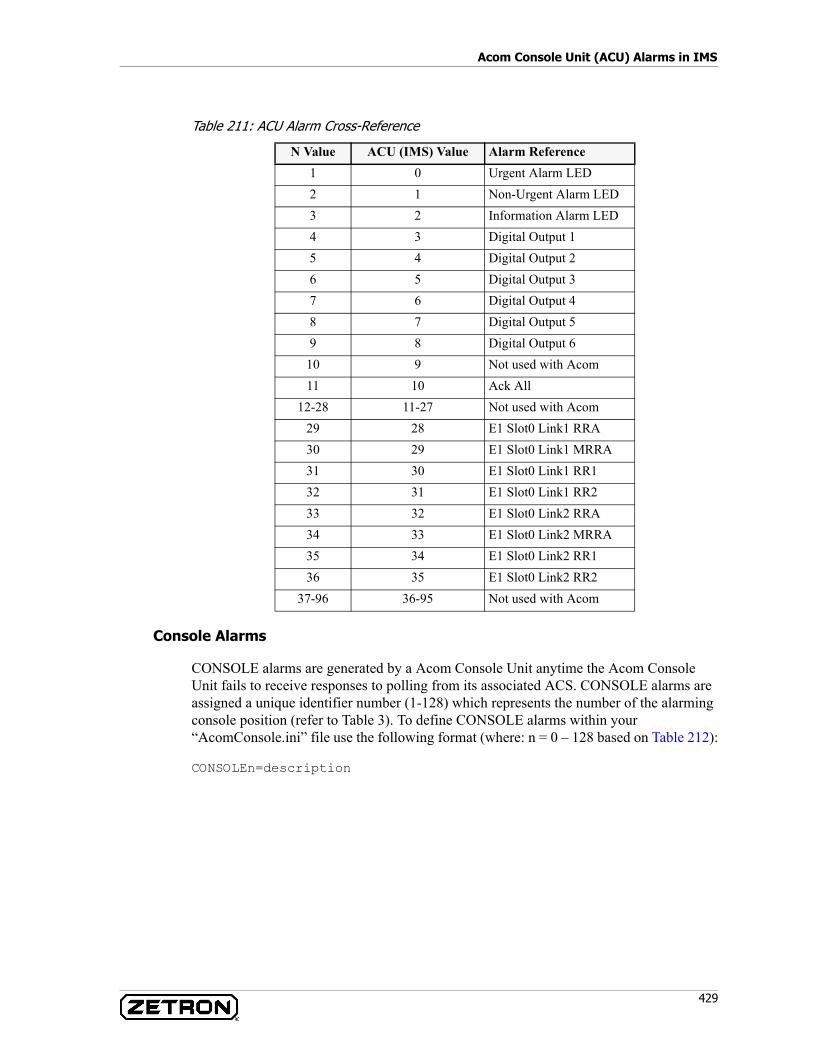
429
Acom Console Unit (ACU) Alarms in IMS
Table 211: ACU Alarm Cross-Reference
Console Alarms
CONSOLE alarms are generated by a Acom Console Unit anytime the Acom Console Unit fails to receive responses to polling from its associated ACS. CONSOLE alarms are assigned a unique identifier number (1-128) which represents the number of the alarming console position (refer to Table 3). To define CONSOLE alarms within your “AcomConsole.ini” file use the following format (where: n = 0 – 128 based on Table 212):
CONSOLEn=description
N Value ACU (IMS) Value Alarm Reference1 0 Urgent Alarm LED2 1 Non-Urgent Alarm LED3 2 Information Alarm LED4 3 Digital Output 15 4 Digital Output 26 5 Digital Output 37 6 Digital Output 48 7 Digital Output 59 8 Digital Output 6
10 9 Not used with Acom11 10 Ack All
12-28 11-27 Not used with Acom29 28 E1 Slot0 Link1 RRA30 29 E1 Slot0 Link1 MRRA31 30 E1 Slot0 Link1 RR132 31 E1 Slot0 Link1 RR233 32 E1 Slot0 Link2 RRA34 33 E1 Slot0 Link2 MRRA35 34 E1 Slot0 Link2 RR136 35 E1 Slot0 Link2 RR2
37-96 36-95 Not used with Acom
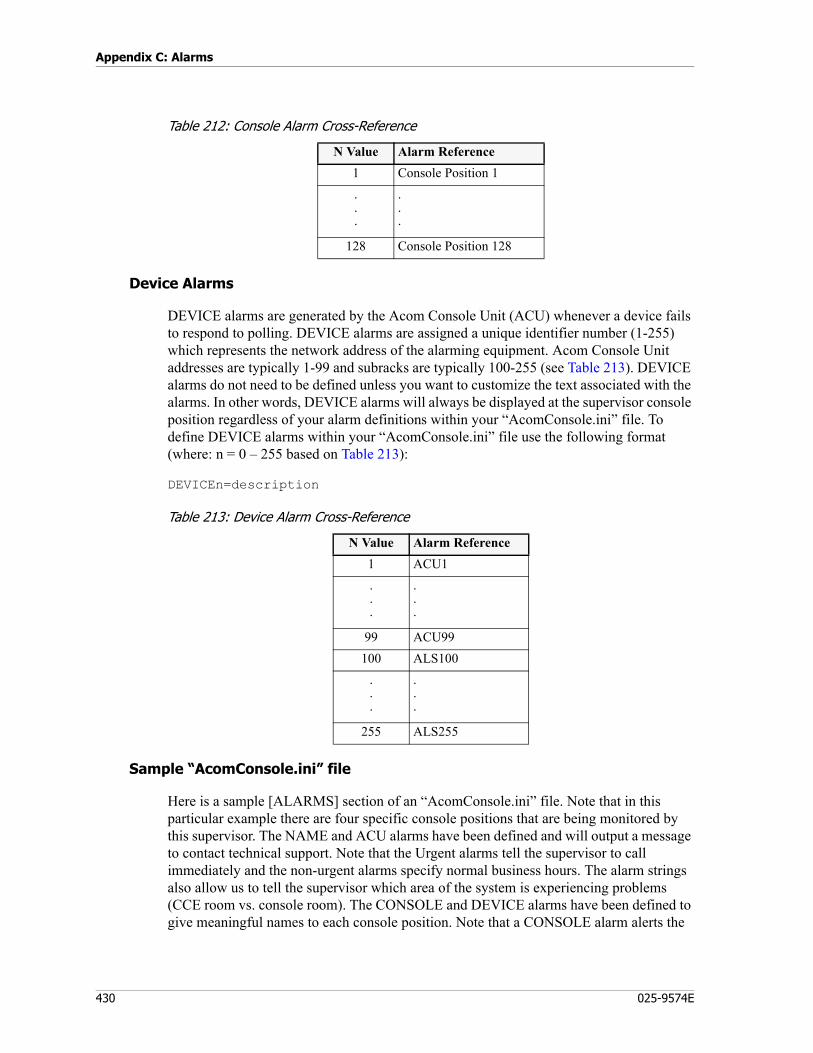
Appendix C: Alarms
430 025-9574E
Table 212: Console Alarm Cross-Reference
Device Alarms
DEVICE alarms are generated by the Acom Console Unit (ACU) whenever a device fails to respond to polling. DEVICE alarms are assigned a unique identifier number (1-255) which represents the network address of the alarming equipment. Acom Console Unit addresses are typically 1-99 and subracks are typically 100-255 (see Table 213). DEVICE alarms do not need to be defined unless you want to customize the text associated with the alarms. In other words, DEVICE alarms will always be displayed at the supervisor console position regardless of your alarm definitions within your “AcomConsole.ini” file. To define DEVICE alarms within your “AcomConsole.ini” file use the following format (where: n = 0 – 255 based on Table 213):
DEVICEn=description
Table 213: Device Alarm Cross-Reference
Sample “AcomConsole.ini” file
Here is a sample [ALARMS] section of an “AcomConsole.ini” file. Note that in this particular example there are four specific console positions that are being monitored by this supervisor. The NAME and ACU alarms have been defined and will output a message to contact technical support. Note that the Urgent alarms tell the supervisor to call immediately and the non-urgent alarms specify normal business hours. The alarm strings also allow us to tell the supervisor which area of the system is experiencing problems (CCE room vs. console room). The CONSOLE and DEVICE alarms have been defined to give meaningful names to each console position. Note that a CONSOLE alarm alerts the
N Value Alarm Reference1 Console Position 1...
.
.
.
128 Console Position 128
N Value Alarm Reference1 ACU1...
.
.
.
99 ACU99100 ALS100
.
.
.
.
.
.
255 ALS255
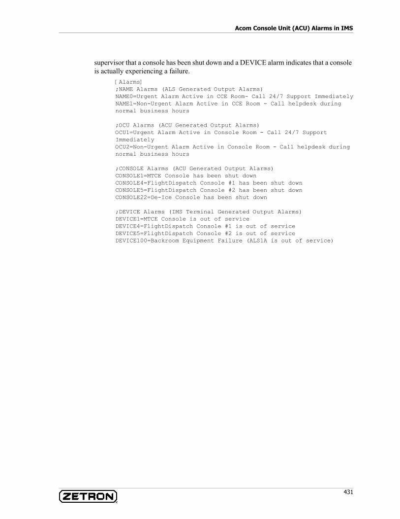
431
Acom Console Unit (ACU) Alarms in IMS
supervisor that a console has been shut down and a DEVICE alarm indicates that a console is actually experiencing a failure.
[Alarms];NAME Alarms (ALS Generated Output Alarms)NAME0=Urgent Alarm Active in CCE Room- Call 24/7 Support ImmediatelyNAME1=Non-Urgent Alarm Active in CCE Room - Call helpdesk during normal business hours
;OCU Alarms (ACU Generated Output Alarms)OCU1=Urgent Alarm Active in Console Room - Call 24/7 Support ImmediatelyOCU2=Non-Urgent Alarm Active in Console Room - Call helpdesk during normal business hours
;CONSOLE Alarms (ACU Generated Output Alarms)CONSOLE1=MTCE Console has been shut downCONSOLE4=FlightDispatch Console #1 has been shut downCONSOLE5=FlightDispatch Console #2 has been shut downCONSOLE22=De-Ice Console has been shut down
;DEVICE Alarms (IMS Terminal Generated Output Alarms)DEVICE1=MTCE Console is out of serviceDEVICE4=FlightDispatch Console #1 is out of serviceDEVICE5=FlightDispatch Console #2 is out of serviceDEVICE100=Backroom Equipment Failure (ALS1A is out of service)

Appendix C: Alarms
432 025-9574E
Index
433
Index
Numerics2-wire interface, 347
AAcom Console Software (ACS), 347Acom Console Unit (ACU), 22, 73, 347Acom DS3 Switch (ADS), 347Acom DS3 Switch (ADS) Subrack, 102Acom Line Subrack (ALS), 347Acom Multiplexer, 347Acom System Overview, 20ACU
COM Ports, 78Mounting, 50specifications, 74
ACU Alarm Definitions, 402ACU Expansion Slots, 83ACU Internal Layout, 76ACU Jumpers, 70ACU Main Board COM Ports 1-3, 78ACU Main Board Connections, 78ACU Main Board Functions, 76ACU Plug-In Modules, 84ACU service port (port 4), 78ADS, 102Alarm Generation, EIE, 166Alarm Generation, EMU, 177Alarm Generation, MSU, 212Alarm Generation, TIE, 258Alarm Indication Signal (AIS), 347Alarm Inputs, MSU, 213Alarm Interface, MSU, 215Alarm System, 371Alarms, 371
ACU, 402ALS, 385General, 383Logs, 373
A-Law, 347ALS, 92
Building Earth Conductors, 97Cable Assemblies, 99Card installation, 94Connection of Cable Shield, 100Earth Connections (Acom), 97Electrical Isolation, 96Grounding, 97Maximum Ratings, 101Physical Characteristics, 101Signal Cable Connections, 99Slot compatibility, 95Specifications, 100Surge Suppression, 100
Antistatic Work Practice, 31As-Built Documentation, 32audible distortion, clipping, 348Audio Interface, MSU, 214Audio Jackbox
Mounting, 51Automatic Call Distribution (ACD), 347Automatic Location Information (ALI), 347Automatic Number Identification (ANI), 347
BBack Room Preparations, 33Backbone Status, 26backbone time slots, 26backplane, 347

Index
434 025-9574E
Backup System Configurations, 320Basic ADS Rack, 103BDM Connector, SMU, 246bearer, 347bearer redundant, 355Bearer Status, 27bearer time slots, 25bit error rate (BER), 348branching connection, 348broadcast connection, 348
CCAD, 348Calling Line Identification (CLI), 348Calling Number Display (CND), 348Capacity, 27Card placement, 107Carrier Operated Relay (COR), 349CAS, 348CCC, 106, 112
Replacing, 278CCC Changeover Details and Specifications, 116CCC Status LED Indications, 114CCC Technical Specifications, 117CCE, 20, 23, 348CCE Components, 73CCE Installation, 43CCE Installation Procedures, 29, 43CCU, 348Changeover Card - 3 Way Coaxial Switch, 118Changeover Card - 48/96 Way Switch, 123Changeover Control Card, 112Changeover Control Card (CCC), 348Changeover Controller Extender Card (CCC-E),
348Changeover Hardware, 106Changeover Subrack, 106Changeover Subrack (COS), 349Changeover Subrack Description, 105Changeover Troubleshooting, 108channel, 348Channel Associated Signaling (CAS), 348Check Cabinet Route, 39Circuit Card Installation (ADS), 104Circuit Card Installation (ALS), 94CLI, 348clipping, 348clock, clock source, 348
Cloning an Acom ALS, 102CMOS, 348CND, 348Coax Loops, 41COC, 348CODEC, 348codirectional interface, 349COM 1 - COM 3, 78Common Control Electronics, 20Common Control Equipment (CCE), 348Common Controller Unit (CCU), 348communication link bearer, 347communications ports, 78companding, 349Computer Aided Dispatch (CAD), 348connection
branching, 348broadcast, 348
Console Installation Procedures, 49Console Loop Installation, 40Console Network Installation, 42Console Room Preparations, 40COR, 349COS, 349COV-R, 123, 349
Replacing, 279COV-R card, 107COV-R Status LED Indications, 126COV-R Technical Specifications, 131COV-R Voice and Data Signals, P2, J1, and J2,
129COV-T, 107, 118, 349
Replacing, 279COV-T Status LED Indications, 121COV-T Technical Specifications, 122COV-V, 123, 349
Replacing, 279COV-V card, 106COV-V Status LED Indications, 126COV-V Technical Specifications, 131COV-V Voice and Data Signals, P4, P2 and P3,
128CRC, 349crosspoint switch, 349CTCSS, 349CTS, 349Cyclic Redundancy Check (CRC), 349
435
Index
DData Circuit Terminating Equip (DCE), 349Data Interface Unit, 142, 151Data Terminal Equipment (DTE), 350DCD, 349DCE, 349DCU, 349
Replacing, 280decadic signaling, 349Deskmic, 57Diagnostic RS-232 Interface, 247Diagnostic Serial Port, SMU, 245DID, 349differential data, 350digital crosspoint switch, 349Digital Input Interface, 81digital inputs, 74digital multiplex hierarchy, 350Digital Output Interface, 82digital outputs, 75DIP Switch Settings, MSU, 207DIU, 350DIU1-2, 142DIU1-2 Technical Specifications, 148DIU1-4, 151DPLL, 350DS, 73DS3, 350DS3 Switch, 24DSP Functions, 83DSP Interfaces, 248DSR, 350DTE, 350DTMF, 350DTR, 350Dual 4W E&M Module, 89Dual E1 Fiber Module, 88Dual E1 Interface Module, 86, 87
EE&M 4-Wire Interface Unit, 168E&M signaling, 350E1 Digital Interfaces, 71earth recall signal, 350EBER, 350EIE, 159, 350EIE Technical Specifications, 166
Electromagnetic Compatibility, 101EMC, 350EMI, 350EMU, 168, 350EMU Connector Detail, 174EMU Status LEDs, 172EMU Technical Specifications, 178Environment, 39Environmental Issues, 321EPIC, 350ESD, 351Ethernet Interface, 247Ethernet Interface, SMU, 250Ethernet Port, SMU, 245ETSI, 351Excessive Bit Error Rate, 350Exchange Interface Card, 162Exchange Interface Equipment (EIE), 350Exchange Interface Unit Card, 159External Interfaces (ACU), 77
FFAS, 351Fault Logs, 373Faults, 319Foot Switch, 69FPGA, 351FPGA and Interface Circuits, 247frame, 25, 351frame alignment, 351Frame Alignment Signal (FAS), 351framer, 351
Ggain, 351Gain Setting and Impedance, TIE, 256General Alarms, 383General Preparation, 30
Hhandshaking, 351Hardware Connections (ACU), 76HDB3, 351HDLC, 195, 351High Density Bipolar of Order 3 (HDB3), 351High-Level Data Link Control (HDLC), 351hot plugging, 351
Index
436 025-9574E
II/O Connector, 248IDF, 351IMS, 352IMS terminal, 352inband signaling, 352Input Alarm Handling, 372Install Additional Power, 35Install Cable Trays, 37Install Grounding System, 36Installation in Subrack
MCU, 211SMU, 249
Installation in Subrack, EMU, 177Installation Procedures, 105Instant Recall Recorder, 352Integrated Management System (IMS), 352Integrated Services Digital Network, 352Integrator IRR
Acom Overview, 58Installation, 61
intersite bearers, 25intersite resources, 25IOM-2, 352IPAT, 352IRR, 352ISB, 25ISDN, 195, 352ISDN Oriented Modular Bus, v2, 352ISDN Primary Access Transceiver, 352
JJTAG Connector, SMU, 246Jumper Link Settings, 207
LLCB, 352Lightning Protection, 38line break, 352line card, 352Line Subrack Alarm Definitions, 385Line Subracks, 92link, 352LIT, 352LMFA, 353Local Area Network (LAN), 21local resources, 26
Log On, 23Logger Card, 131Logs
Alarm, 373loop detect, 353loop out, 353loop seize, 353loop signaling, 355LOS, 353loss of sync, 353
MMain Control Unit, 353MAINTENANCE LOG, 320Maintenance Terminal Interface, 250Manual Reset, 48master clock, 353MCU, 353MCU Card Replacement (ADS), 297MCU Card Replacement (ALS), 293MCU Installation in ADS, 196MCU Installation in LSR, 196MCU Part Numbers and Compatibility, 104, 180MCU Technical Specifications, 197MDF, 353Model 3030 PSAP TDD, 64Mount Acom Punchdown Blocks on Demarc
Wall, 38MSU, 353MSU Interfaces, 209MSU Technical Specifications, 213multiframe, 353Multiplexer Supply Unit, 202MUSAC, 353MUX, 353
Nnon urgent alarm, 353NOS, 353NRZ, 353
OOAM, 354Operating Environment, 30Operator Active Lamp, 65Operator’s Audio Module, 85Operator’s Audio Module LEDs, 85

437
Index
order wire, 354
Ppartial time slot allocation, 354PCM, 354PCM-30, 355PE, 355Phase Locked Loop, 355PLL, 355Preventative Maintenance, 319primary MCU, 355primary rate, 355Programmable Alarms, MSU, 213Protective Earth (PE), 355PSTN, 355PTT, 355Pulse Code Modulation, 354
RRack Configuration, 103Rack Unit, 93Radio Interface Unit (RIU), 224Recommended Installer Materials and
Equipment, 33Recorded Voice Announcement Card, 235Recovered Clock, 355redundant bearer, 355Reference Voltage Strapping, 207Replacing Acom Cards and Devices, 277Replacing CCCs, 278Replacing COV-R Cards, 279Replacing COV-T Cards, 279Replacing COV-V Cards, 279Replacing Daughter Cards in a Acom Console
Unit, 290Replacing DCU Cards, 280Replacing EIE Cards, 291Replacing EMU Cards, 291Replacing Jackboxes, 292Replacing MCU Cards in an ADS, 297Replacing MCU Cards in an ALS, 293Replacing MSU Cards, 301Replacing RVA Cards, 302Replacing SMU Cards, 302, 303Replacing Telephone Radio Handset Interfaces,
305Replacing UIO Cards, 306
Replacing YIE Cards, 291Reset, manual, 48RGU, 355ring cadence, 355Ring Cadence and Ring Tone, TIE, 256Ring Generator Unit (RGU), 215ring out signaling, 355ring signal, 355ring voltage, 355RIU Card, 224RMS, 355RRA, 355RS-232, 78RS-485, 78RTC, 194, 355RTS, 355RUN LED Indicator, SMU, 244RVA, 355RVA Card, 235RX, 355RXD, 355
SSafety, 30Safety Extra Low Voltage, 30Safety Extra Low Voltage (SELV), 356SCC, 356SDI, 356SELV, 30, 356serial ports, 78service word, 356signaling, 356Signaling Management Unit, 240slave clock, 356slip, 356slot, 356SMB, 356SMU, 240, 356SMU Daughter Boards, 248SMU Technical Specifications, 249SoundBlaster
configuration, 60Speakers
Zetron-Brand, 54Specifications (ALS), 100Status LED Indicators, MCU, 186Status LED Indicators, MSU, 205Strap Settings, UIO, 264
Index
438 025-9574E
sub-multiframe, 356subrack, 356subrack backplane, 347Subrack Mounting, 93Subracks (additional), 108subrate communication, 356synchronous communication, 356System Architecture, 31System Card Descriptions, 111System Console Connectors and pin-outs, 23System Console Electrical Requirements, 23System Console Hardware Requirements, 22System Power Up Sequence, 46System Reset, 206System Reset, EMU, 173System Reset, MCU, 190System Reset, TIE, 255
TTDM, 356Telecom Network Voltage, 30Telecommunication Network Voltage (TNV),
357Telephone Interface Unit, 252terminal, IMS, 352Testing Backup Systems, 321Testing of New/Existing Circuits, 34TIE, 252, 356TIE Connections, 256TIE Installation, 258TIE Interfaces, 254Time Division Multiplexing (TDM), 356time slot, 25Time Slot (TS), 357time slots, backbone, 26
TNV, 30, 357traffic, 357transceiver, 357TRC, 357TRHI
Mounting, 53Troubleshooting, 108, 325Troubleshooting Actions, 329TS, 357TSI, 357TTL, 357Twisted Pair Loops, 40TX, 357TXD, 357
UUIO, 260, 357UIO Input Interface, 262UIO Interfaces, 262UIO Output Interface, 262UMS, 357Universal Input/Output, 260urgent alarm, 357User Management System (UMS), 357
VVF, 357Voice Frequency (VF), 357VoIP Line Subrack, 101
WWatchdog Alarm, MSU, 213Watchdog Timer, 357