Embed Size (px)
Citation preview
FEATURE: CONDITION MONITORING
Industrial March/April 2017 31
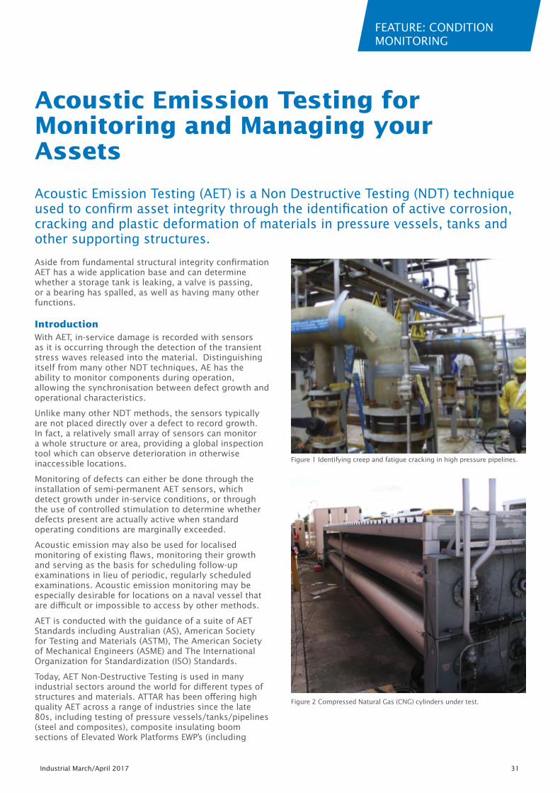
Aside from fundamental structural integrity confirmation AET has a wide application base and can determine whether a storage tank is leaking, a valve is passing, or a bearing has spalled, as well as having many other functions.
IntroductionWith AET, in-service damage is recorded with sensors as it is occurring through the detection of the transient stress waves released into the material. Distinguishing itself from many other NDT techniques, AE has the ability to monitor components during operation, allowing the synchronisation between defect growth and operational characteristics.
Unlike many other NDT methods, the sensors typically are not placed directly over a defect to record growth. In fact, a relatively small array of sensors can monitor a whole structure or area, providing a global inspection tool which can observe deterioration in otherwise inaccessible locations.
Monitoring of defects can either be done through the installation of semi-permanent AET sensors, which detect growth under in-service conditions, or through the use of controlled stimulation to determine whether defects present are actually active when standard operating conditions are marginally exceeded.
Acoustic emission may also be used for localised monitoring of existing flaws, monitoring their growth and serving as the basis for scheduling follow-up examinations in lieu of periodic, regularly scheduled examinations. Acoustic emission monitoring may be especially desirable for locations on a naval vessel that are difficult or impossible to access by other methods.
AET is conducted with the guidance of a suite of AET Standards including Australian (AS), American Society for Testing and Materials (ASTM), The American Society of Mechanical Engineers (ASME) and The International Organization for Standardization (ISO) Standards.
Today, AET Non-Destructive Testing is used in many industrial sectors around the world for different types of structures and materials. ATTAR has been offering high quality AET across a range of industries since the late 80s, including testing of pressure vessels/tanks/pipelines (steel and composites), composite insulating boom sections of Elevated Work Platforms EWP’s (including
Acoustic Emission Testing (AET) is a Non Destructive Testing (NDT) technique used to confirm asset integrity through the identification of active corrosion, cracking and plastic deformation of materials in pressure vessels, tanks and other supporting structures.
Acoustic Emission Testing for Monitoring and Managing your Assets
Figure 1 Identifying creep and fatigue cracking in high pressure pipelines.
Figure 2 Compressed Natural Gas (CNG) cylinders under test.
FEATURE: CONDITION MONITORING
32 Industrial Eye March/April 2017
participating in the development of the Australian Standard AS 4748 – 2001), structures (e.g. bridges) and the monitoring of creep in high pressure, high temperature steam lines.
ApplicationsStructure Stimulation
The application of a controlled stimulation, either progressively applied or applied in stages, with the presence of AET sensors, allows the structure to be monitored during loading conditions which are similar or greater than their standard operating conditions.
Smaller defects which are active at operating stress levels, which might otherwise be missed by other less sensitive NDT methods, can be detected, located and then marked for inspection using complimentary NDT methods for sizing.
Utilising the existing International Standards and ATTAR’s ability to tailor specific AET procedures for a variety of applications, provides engineers with the means of gaining confidence in the testing of an asset. High-risk assets, such as vessels, cylinders, pipelines and more, are safely monitored during a controlled stimulation process.
Corrosion Monitoring
ATTAR works with clients on tank integrity using advanced testing as part of a risk based inspection and drawing upon the requirements AS1940 and API653.
AET is regularly used to assess tank floors, where access to this region is otherwise impossible without the difficult, lengthy and costly processes for draining, gaining access and cleaning. Where a regular programme of AET is undertaken and included in the assessment of the Risk Based Inspection (RBI) programme, good judgements on the tank condition can be made and internal inspections deemed not necessary, until the RBI assessment results indicate a deleterious change.
Where tanks have been in service for some time without an inspection, ATTAR can assist to prioritise which tank or vessel to inspect and when internal inspections could safely fit with operational schedules and plans. Following this inspection giving a base condition, AET can then be used with greater confidence to monitor the condition of the plant.
Fuel, process and waste-water tanks can remain operationally ready by reducing the need for internal inspections, through the introduction of an RBI programme that incorporates AET.
AET can take a matter of 3 to 5 hours with little interruption to operations.
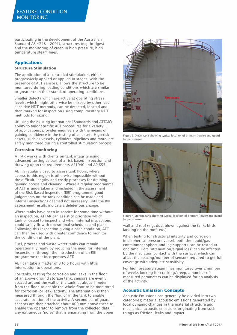
For tanks, testing for corrosion and leaks in the floor of an above ground storage tank, sensors are evenly spaced around the wall of the tank, at about 1 meter from the floor, to enable the whole floor to be monitored for corrosion (or leak) activity. The attenuation is then measured through the “liquid” in the tank to enable accurate location of the activity. A second set of guard sensors are then attached about 800 mm above these to enable the operator to remove from the collected data, any extraneous “noise” that is emanating from the upper
wall and roof (e.g. dust blown against the tank, birds landing on the roof, etc.)
When testing for structural integrity and corrosion in a spherical pressure vessel, both the liquid/gas containment sphere and leg supports can be tested at one time. Here “attenuation/signal loss” can be affected by the insulation contact with the surface, which can affect the spacing/number of sensors required to get full coverage with adequate sensitivity.
For high pressure steam lines monitored over a number of weeks looking for cracking/creep, a number of measured parameters can be displayed for an analysis of the activity.
Acoustic Emission ConceptsAcoustic Emissions can generally be divided into two categories; material acoustic emissions generated by local dynamic changes in the material structure and mechanical acoustic emissions originating from such things as friction, leaks and impact.
Figure 3 Diesel tank showing typical location of primary (lower) and guard (upper) sensor.
Figure 4 Storage tank showing typical location of primary (lower) and guard (upper) sensor.
FEATURE: CONDITION MONITORING
Industrial March/April 2017 33
Sensors have been designed to operate in the 30 to 300 KHz range, to enable better resolution of emissions that are being measured. The AE equipment also collects the waveform of the emission, enabling analysis of the mechanism that is giving rise to the emissions.
The morphology of the detected transient elastic waves varies depending on the type of emission. The characterisation of the waves is made possible using high-speed, high-resolution hardware, capable of modelling both the physical and dimensional waveform properties. Using these characteristics, distinguishing between different noise source types becomes possible.
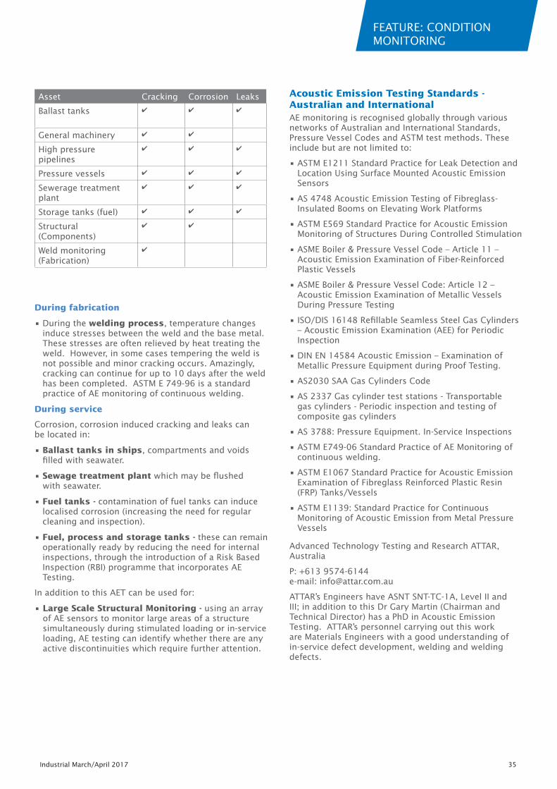
Two waveforms are shown below. Figure 11 is typical of crack-like acoustic emissions, where it presents as a short, sharp signal. Figure 12 is more consistent with mechanical rubbing, where there is a longer duration, and a more even appearance.
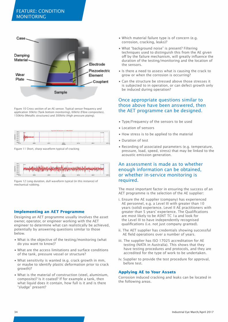
AE sensors are typically piezoelectric and most include a preamplifier to reduce external influence on signals. The sensors are attached and “coupled” to the material surface, with calibration confirmed with the sensor located on the material of the structure to be tested.
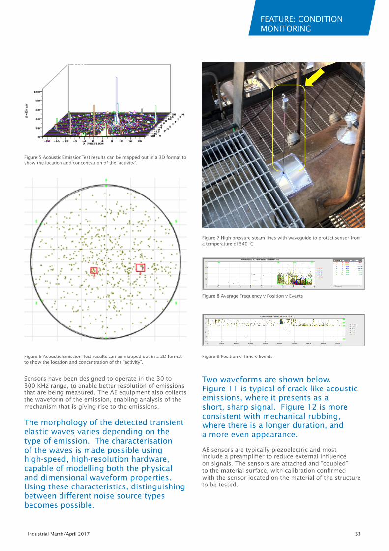
Figure 5 Acoustic EmissionTest results can be mapped out in a 3D format to show the location and concentration of the “activity”.
Figure 7 High pressure steam lines with waveguide to protect sensor from a temperature of 540˚C
Figure 8 Average Frequency v Position v Events
Figure 9 Position v Time v EventsFigure 6 Acoustic Emission Test results can be mapped out in a 2D format to show the location and concentration of the “activity”.
FEATURE: CONDITION MONITORING
34 Industrial Eye March/April 2017
Implementing an AET ProgrammeDesigning an AET programme usually involves the asset owner, operator, or engineer working with the AET engineer to determine what can realistically be achieved, potentially by answering questions similar to those below.
• What is the objective of the testing/monitoring (what do you want to know)?
• What are the access limitations and surface conditions of the tank, pressure vessel or structure?
• What sensitivity is wanted (e.g. crack growth in mm, or maybe to identify plastic deformation prior to crack growth)?
• What is the material of construction (steel, aluminium, composite)? Is it coated? If for example a tank, then what liquid does it contain, how full is it and is there “sludge” present?
• Which material failure type is of concern (e.g. corrosion, cracking, leaks)?
• What “background noise” is present? Filtering techniques used to distinguish this from the AE given off by the failure mechanism, will greatly influence the duration of the testing/monitoring and the location of the sensors.
• Is there a need to assess what is causing the crack to grow or when the corrosion is occurring?
• Can the structure be stressed above those stresses it is subjected to in operation, or can defect growth only be induced during operation?
Once appropriate questions similar to those above have been answered, then the AET programme can be designed.
• Type/Frequency of the sensors to be used
• Location of sensors
• How stress is to be applied to the material
• Duration of test
• Recording of associated parameters (e.g. temperature, pressure, load, speed, stress) that may be linked to the acoustic emission generation.
An assessment is made as to whether enough information can be obtained, or whether in-service monitoring is required.
The most important factor in ensuring the success of an AET programme is the selection of the AE supplier:
i. Ensure the AE supplier (company) has experienced AE personnel, e.g. a Level III with greater than 10 years (solid) experience. Level II AE practitioners with greater than 5 years’ experience. The Qualifications are most likely to be ASNT TC 1a and look for the Level III to have independently recognised qualifications (i.e. not just company granted).
ii. The AET supplier has credentials showing successful AE field operations over a number of years.
iii. The supplier has ISO 17025 accreditation for AE testing (NATA in Australia). This shows that they have testing procedures and protocols, and they are accredited for the type of work to be undertaken.
iv. Supplier to provide the test procedure for approval, before test.
Applying AE to Your AssetsCorrosion induced cracking and leaks can be located in the following areas.
Figure 10 Cross section of an AE sensor. Typical sensor frequency and application 30kHz (Tank bottom monitoring), 60kHz (Fibre composites), 150kHz (Metallic structures) and 300kHz (High pressure piping).
Figure 11 Short, sharp waveform typical of cracking
Figure 12 Long duration, dull waveform typical (in this instance) of mechanical rubbing.
FEATURE: CONDITION MONITORING
Industrial March/April 2017 35
Asset Cracking Corrosion Leaks
Ballast tanks ✔ ✔ ✔
General machinery ✔ ✔
High pressure pipelines
✔ ✔ ✔
Pressure vessels ✔ ✔ ✔
Sewerage treatment plant
✔ ✔ ✔
Storage tanks (fuel) ✔ ✔ ✔
Structural (Components)
✔ ✔
Weld monitoring (Fabrication)
✔
During fabrication
• During the welding process, temperature changes induce stresses between the weld and the base metal. These stresses are often relieved by heat treating the weld. However, in some cases tempering the weld is not possible and minor cracking occurs. Amazingly, cracking can continue for up to 10 days after the weld has been completed. ASTM E 749-96 is a standard practice of AE monitoring of continuous welding.
During service
Corrosion, corrosion induced cracking and leaks can be located in:
• Ballast tanks in ships, compartments and voids filled with seawater.
• Sewage treatment plant which may be flushed with seawater.
• Fuel tanks - contamination of fuel tanks can induce localised corrosion (increasing the need for regular cleaning and inspection).
• Fuel, process and storage tanks - these can remain operationally ready by reducing the need for internal inspections, through the introduction of a Risk Based Inspection (RBI) programme that incorporates AE Testing.
In addition to this AET can be used for:
• Large Scale Structural Monitoring - using an array of AE sensors to monitor large areas of a structure simultaneously during stimulated loading or in-service loading, AE testing can identify whether there are any active discontinuities which require further attention.
Acoustic Emission Testing Standards - Australian and InternationalAE monitoring is recognised globally through various networks of Australian and International Standards, Pressure Vessel Codes and ASTM test methods. These include but are not limited to:
• ASTM E1211 Standard Practice for Leak Detection and Location Using Surface Mounted Acoustic Emission Sensors
• AS 4748 Acoustic Emission Testing of Fibreglass-Insulated Booms on Elevating Work Platforms
• ASTM E569 Standard Practice for Acoustic Emission Monitoring of Structures During Controlled Stimulation
• ASME Boiler & Pressure Vessel Code – Article 11 – Acoustic Emission Examination of Fiber-Reinforced Plastic Vessels
• ASME Boiler & Pressure Vessel Code: Article 12 – Acoustic Emission Examination of Metallic Vessels During Pressure Testing
• ISO/DIS 16148 Refillable Seamless Steel Gas Cylinders – Acoustic Emission Examination (AEE) for Periodic Inspection
• DIN EN 14584 Acoustic Emission – Examination of Metallic Pressure Equipment during Proof Testing.
• AS2030 SAA Gas Cylinders Code
• AS 2337 Gas cylinder test stations - Transportable gas cylinders - Periodic inspection and testing of composite gas cylinders
• AS 3788: Pressure Equipment. In-Service Inspections
• ASTM E749-06 Standard Practice of AE Monitoring of continuous welding.
• ASTM E1067 Standard Practice for Acoustic Emission Examination of Fibreglass Reinforced Plastic Resin (FRP) Tanks/Vessels
• ASTM E1139: Standard Practice for Continuous Monitoring of Acoustic Emission from Metal Pressure Vessels
Advanced Technology Testing and Research ATTAR, Australia
P: +613 9574-6144 e-mail: [email protected]
ATTAR’s Engineers have ASNT SNT-TC-1A, Level II and III; in addition to this Dr Gary Martin (Chairman and Technical Director) has a PhD in Acoustic Emission Testing. ATTAR’s personnel carrying out this work are Materials Engineers with a good understanding of in-service defect development, welding and welding defects.