Embed Size (px)
Citation preview
. .
" .
INTERNATIONAL STANDARD
- Reproduced By GLOBAL ii. . ENGINEERING DOCUMENTS . a With The Permission Of ISO
__.-I? Under Royalty Agreement
ISO 9613-2
First edition 1996-12-15
Acoustics - Attenuation of sound during propagation outdoors -
Part 2: General method of calculation
Acoustique - Attenuation du son /ors de sa propagation a /'air fibre -
Partie 2: Methode generale de ca/cul
-~-- -- -- --- -
~ISOJ -~-- -- -;;:-.;;-=======-;-;;
Reference number 1::;n QR11.?·100RII=\
ISO 9613-2:1996(E)
Foreword
ISO (the International Organization for Standardization) is a worldwide federation of national standards bodies (ISO member bodies). The work of preparing International Standards is normally carried out through ISO technical committees. Each member body interested in a subject for which a technical committee has been established has the right to be represented on that committee. International organizations, governmental and non-governmental, in liaison with ISO, also take part in the work. ISO collaborates closely with the International Electrotechnical Commission (IEC) on all matters of electrotechnical standardization.
Draft International Standards adopted by the technical committees are circulated to· the member bodies for voting. Publication as an International Standard requires approval by at least 75 % of the member bodies casting a vote.
International Standard ISO 9613-2 was prepared by Technical Committee ISO/TC 43, Acoustics, Subcommittee SC 1, Noise.
ISO 9613 consists of the following parts, under the general title Acoustics - Attenuation of sound during propagation outdoors:
Part 1: Calculation of the absorption of sound by the atmosphere
Part 2: General method of calculation
Part 1 is a detailed treatment restricted to the attenuation by atmospheric absorption processes. Part 2 is a more approximate and empirical treatment of a wider subject - the attenuation by all physical mechanisms.
Annexes A and B of this part of ISO 9613 are for information only.
© ISO 1996
All rights reserved. Unless otherwise specified, no part of this publication may be reproduced or utilized in any form or by any means, electronic or mechanical, including photocopying and microfilm, without permission in writing from the publisher.
International Organization for Standardization Case Postale 56 • CH-1211 Geneve 20 • Switzerland
Printed in Switzerland
,, ,.
©ISO ISO 9613-2:1996(E)
Introduction
The ISO 1996 series of standards specifies methods for the description of noise outdoors in community environments. Other standards, on the other hand, specify methods for determining the sound power levels emitted by various noise sources, such as machinery and specified equipment (ISO 3740 series). or industrial plants (ISO 8297). This part of ISO 9613 is intended to bridge the gap between these two types of standard, to enable noise levels in the community to be predicted from sources of known sound emission. The method described in this part of ISO 9613 is general in the sense that it may be applied to a wide variety of noise sources, and covers most of the major mechanisms of attenuation. There are, however, constraints on its use, which arise principally from the description of environmental noise in the ISO 1996 series of standards.

. INTERNATIONAL STANDARD © ISO ISO 9613-2:1996(E)
Acoustics - Attenuation of sound during propagation outdoors -
Part 2: General method of calculation
1 Scope
This part of ISO 9613 specifies an engineering method for calculating the attenuation of sound during propagation outdoors in order to predict the levels of environmental noise at a distance from a variety of sources. The method predicts the equivalent continuous A-weighted sound pressure level (as described in parts 1 to 3 of ISO 1996) under meteorological conditions favourable to propagation from sources of known sound emission.
These conditions are for downwind propagation, as specified in 5.4.3.3 of ISO 1996-2: 1987 or, equivalently, propagation under a well-developed moderate groundbased temperature inversion, such as commonly occurs at night. Inversion conditions over water surfaces are not covered and may result in higher sound pressure levels than predicted from this part of ISO 9613.
The method also predicts a long-term average Aweighted sound pressure level as specified in ISO 1996-1 and ISO 1996-2. The long-term average Aweighted sound pressure level encompasses levels for a wide variety of meteorological conditions.
The method specified in this part of ISO 9613 consists specifically of octave-band algorithms (with nominal midband frequencies from 63 Hz to 8 kHz) for calculating the attenuation of sound which originates from a point sound source, or an assembly of point sources. The source (or sources} may be moving or stationary. Specific terms are provided in the algorithms for the following physical effects:
geometrical divergence;
atmospheric absorption;
ground effect;
reflection from surfaces;
screening by obstacles.
Additional information concerning propagation through housing, foliage and industrial sites is given in annex A.
This method is applicable in practice to a great variety of noise sources and environments. It is applicable, directly or indirectly, to most situations concerning road or rail traffic, industrial noise sources, construction activities, and many other ground-based noise · sources. It does not apply to sound from aircraft in flight, or to blast waves from mining, military or similar operations.
To apply the method of this part of ISO 9613, several parameters need to be known with respect to the geometry of the source and of the environment, the ground surface characteristics, and the source strength in terms of octave-band sound power levels for directions relevant to the propagation.
NOTE 1 If only A-weighted sound power levels of the sources are known, the attenuation terms for 500 Hz may be used to estimate the resulting attenuation.
The accuracy of the method and the limitations to its use in practice are described in clause 9.
2 Normative references
The following standards contain prov1s1ons which, through reference in this text, constitute provisions of this part of ISO 9613. At the time of publication, the editions indicated were valid. All standards are subject to revision, and parties to agreements based on this part of ISO 9613 are encouraged to investigate the possibility of applying the most recent editions of the standards indicated below. Members of IEC and ISO maintain registers of currently valid International Standards.
ISO 1996-1: 1982, Acoustics - Description and measurement of environmental noise - Part 7: Basic quantities and procedures.
ISO 9613-2:1996(E)
ISO 1996-2:1987, Acoustics - Description and measurement of environmental noise - Part 2: Acquisition of data pertinent to land use.
ISO 1996-3: 1987, Acoustics - Description and measurement of environmental noise - Part 3: Application to noise limits.
©ISO
... ( 1)
where
ISO 9613-1: 1993, Acoustics - Attenuation of sound during propagation outdoors - Part 1: Calculation of the absorption of sound by the atmosphere.
PA(t) is the instantaneous A-weighted sound pressure, in pascals;
I EC 651: 1979, Sound level meters, and Amendment 1:1993.
Po is the reference sound pressure (= 20 x 10-6 Pa);
T is a specified time interval, in seconds.
3 Definitions The A-frequency weighting is that specified for sound level meters in IEC 651.
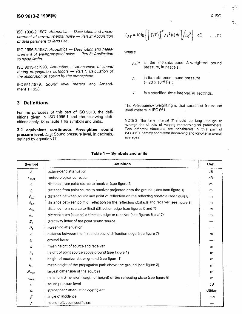
For the purposes of this part of ISO 9613, the definitions given in ISO 1996-1 and the following definitions apply. (See table 1 for symbols and units.)
3.1 equivalent continuous A-weighted sound pressure level, LA7: Sound pressure level, in decibels, defined by equation (1 ):
NOTE 2 The time interval T should be long enough to average the effects of varying meteorological parameters. Two different situations are considered in this part of ISO 9613, namely short-term downwind anq long-term overall averages.
Table 1 - Symbols and units
Symbol Definition Unit
A octave-band attenuation dB
Cmet meteorological correction dB
d distance from point source to receiver (see figure 3) m
dp distance from point source to receiver projected onto the ground plane (see figure 1) m
ds,o distance between source and point of reflection on the reflecting obstacle (see figure 8) m
do,r distance between point of reflection on the reflecting obstacle and receiver (see figure 8) m
dss distance from source to (first) diffraction edge (see figures 6 and 7) m
dsr distance from (second) diffraction edge to receiver (see figures 6 and 7) m
D1 directivity index of the point sound source -Dz screening attenuation -e distance between the first and second diffraction edge (see figure 7) m
G ground factor -h mean height of source and receiver m
hs height of point source above ground (see figure 1) m
h, height of receiver above ground (see figure 1 J m
hm mean height of the propagation path above the ground (see figure 3) m
Hmax largest dimension of the sources m
lmin minimum dimension (length or height) of the reflecting plane (see figure 8) m
L sound pressure level dB
a atmospheric attenuation coefficient dB/km
[3 angle of incidence rad
p sound reflection coefficient -
""
©ISO
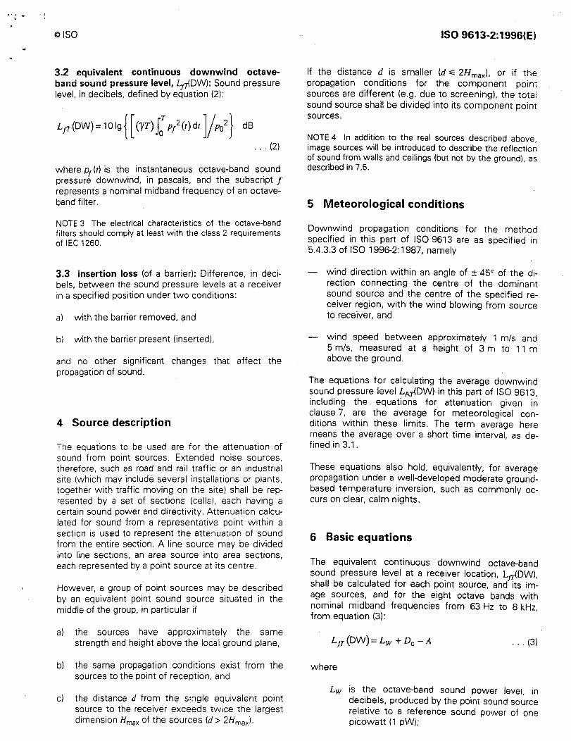
3.2 equivalent continuous downwind octaveband sound pressure level, Lp{DW): Sound pressure level, in decibels, defined by equation (2):
... (2)
where p1 (t) is the instantaneous octave-band sound pressure downwind, in pascals, and the subscript f represents a nominal midband frequency of an octaveband filter.
NOTE 3 The electrical characteristics of the octave-band filters should comply at least with the class 2 requirements of IEC 1260.
3.3 insertion loss (of a barrier): Difference, in decibels, between the sound pressure levels at a receiver in a specified position under two conditions:
a) with the barrier removed, and
b) with the barrier present (inserted),
and no other significant changes that affect the propagation of sound.
4 Source description
The equations to be used are for the attenuation of sound from point sources. Extended noise sources, therefore, such as road and rail traffic or an industrial site (which mav include several installations or plants, together with traffic moving on the site) shall be represented by a set of sections (cells). each having a certain sound power and directivity. Attenuation calculated for sound from a representative point within a section is used to represent the attenuation of sound from the entire section. A line source may be divided into line sections, an area source into area sections, each represented by a point source at its centre.
However, a group of point sources may be described by an equivalent point sound source situated in the middle of the group, in particular if
al the sources have approximately the same strength and height above the local ground plane,
b) the same propagation conditions exist from the sources to the point of reception. and
c) the distance d from the single equivalent point source to the receiver exceeds twice the largest dimension Hmax of the sources (d > 2Hmaxl-
ISO 9613-2:1996(E)
If the distance d is smaller (d..;; 2Hrnaxl, or if the propagation conditions for the component point sources are different (e.g. due to screening), the total sound source shall be divided into its component point sources.
NOTE 4 In addition to the real sources described above image sources will be introduced to describe the reflectio~ of sound from walls and ceilings (but not by the ground), as described in 7.5.
5 Meteorological conditions
Downwind propagation conditions for the method specified in this part of ISO 9613 are as specified in 5.4.3.3 of ISO 1996-2: 1987, namely
wind direction within an angle of ± 45° of the direction connecting the centre of the dominant sound source and the centre of the specified receiver region, with the wind blowing from source to receiver, and
wind speed between approximately 1 m/s and 5 m/s, measured at a height of 3 m to 11 m above the ground.
The equations for calculating the average downwind sound pressure level LArJ..DW) in this part of ISO 9613, including the equations for attenuation given in clause 7, are the average for meteorological conditions within these limits. The term average here means the average over a short time interval. as defined in 3.1.
These equations also hold, equivalently, for average propagation under a well-developed moderate groundbased temperature inversion, such as commonly occurs on clear, calm nights.
6 Basic equations
The equivalent continuous downwind octave-band sound pressure level at a rece_iver location, L.,rJ..DW), shall be calculated for each point source, and its image sources, and for the eight octave bands with nominal midband frequencies from 63 Hz to 8 kHz, from equation (3):
... (3)
where
Lw is the octave-band sound power level, in decibels, produced by the point sound source relative to a reference sound power of one picowatt (1 pW);
ISO 9613-2:1996(E)
De is the directivity correction, in decibels, that describes the extent by which the equivalent continuous sound pressure level from the point sound source deviates in a specified direction from the level of an omnidirectional point sound source producing sound power level Lw: De equals the directivity index D1 of the point sound source plus an index Dn that accounts for sound propagation into solid angles less than 41t steradians; for an omnidirectional point sound source radiating into free space, De= 0 dB;
A is the octave-band attenuation, in decibels, that occurs during propagation from the point sound source to the receiver.
NOTES
5 The letter symbol A (in italic type) signifies attenuation in this part of ISO 9613 except in subscripts, where it designates the A-frequency weighting (in roman type).
6 Sound power levels in equation (3) may be determined from measurements, for example as described in the ISO 3740 series (for machinery) or in ISO 8297 (for industrial plants).
The attenuation term A in equation (3) is given by equation (4):
... (4)
where
Adiv is the attenuation due to geometrical divergence (see 7.1);
Aatm is the attenuation due to atmospheric absorption (see 7.2);
is the attenuation due to the ground effect (see 7.3);
is the attenuation due to a barrier (see 7.4);
Amisc is the attenuation due to miscellaneous other effects (see annex A).
General methods for calculating the first four terms in equation (4) are specified in this part of ISO 9613. Information on three contributions to the last term, Amise
(the attenuation due to propagation through foliage, industrial sites and areas of houses), is given in annex A.
The equivalent continuous A-weighted downwind sound pressure level shall be obtained by summing the contributing time-mean-square sound pressures c;:ilculated accordino to equations (3) and (4) for each
©ISO
point sound source, for each of their image sources, and for each octave band, as specified by equation (5):
LArlDWJ; 1019 l:t[t 10°-1[LJTW)+A.rUl]]l dB
1,=1 J=1 ... (5)
where
n is the number of contributions i (sources and paths);
j is an index indicating the eight standard octave-band midband frequencies from 63 Hz to 8 kHz;
A1 denotes the standard A-weighting (see IEC 651).
The long-term average A-weighted sound pressure level LAr(L Tl shall be calculated according to
... (6)
where Cmet is the meteorological correction described in clause 8.
The calculation and significance of the various terms in equations (1) to (6) are explained in the following clauses. For a more detailed treatment of the attenuation terms, see the literature references given in annex B.
7 Calculation of the attenuation terms
7 .1 Geometrical divergence (Adivl
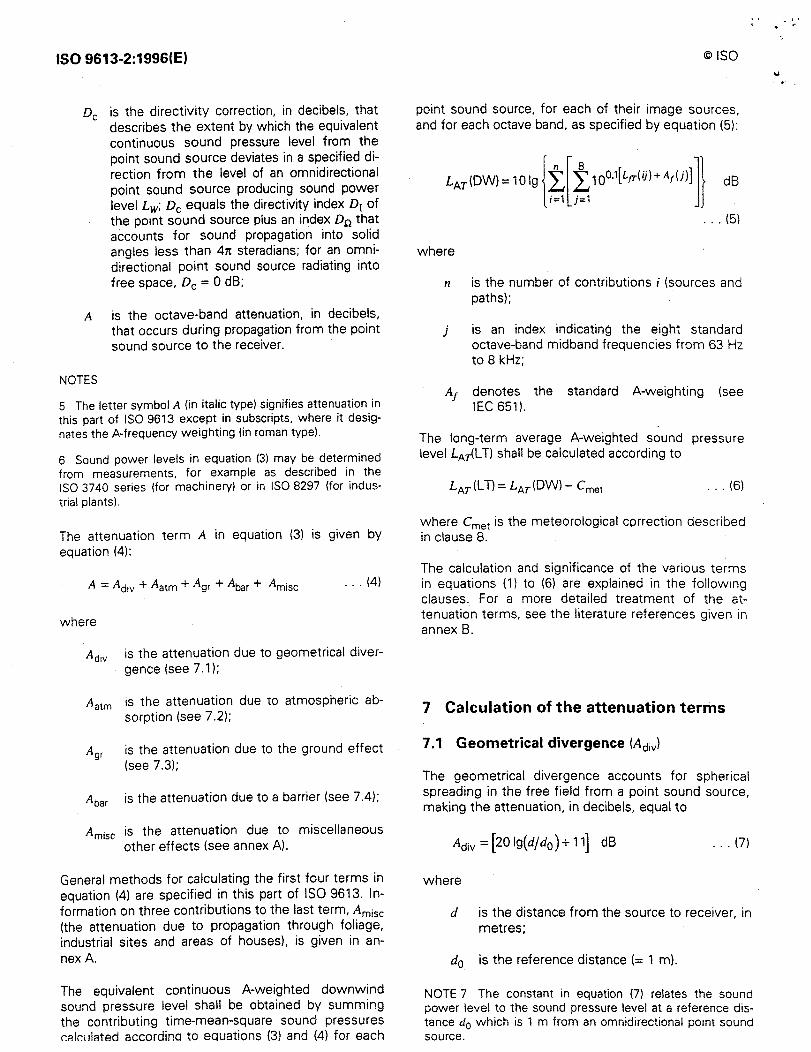
The geometrical divergence accounts for spherical spreading in the free field from a point sound source, making the attenuation, in decibels, equal to
Adiv=[201g(d/d0 )+11] dB ... (7)
where
d is the distance from the source to receiver, in metres;
do is the reference distance (= 1 ml.
NOTE 7 The constant in equation (7) relates the sound power level to the sound pressure level at a reference distance d0 which is 1 m from an omnidirectional point sound source.
'' r
@ISO
7 .2 Atmospheric absorption (Aatml
The attenuation due to atmospheric absorption Aatm• in decibels, during propagation through a distance d, in metres, is given by equation (8):
Aatm = ad/1 000 ... (8)
where a is the atmospheric attenuation coefficient, in decibels per kilometre, for each octave band at the midband frequency (see table 2).
For values of a at atmospheric conditions not covered in table 2, see ISO 9613-1.
NOTES
8 The atmospheric attenuation coefficient depends strongly on the frequency of the sound, the ambient temperature and relative humidity of the air, but only weakly on the ambient pressure.
9 For calculation of environmental noise levels, the atmospheric attenuation coefficient should be based on average values determined by the range of ambient weather which is relevant to the locality.
7 .3 Ground effect (A9rl
7 .3.1 General method of calculation
Ground attenuation, Agr- is mainly the result of sound reflected by the ground surface interfering with the sound propagating directly from source to receiver.
ISO 9613-2:1996(E)
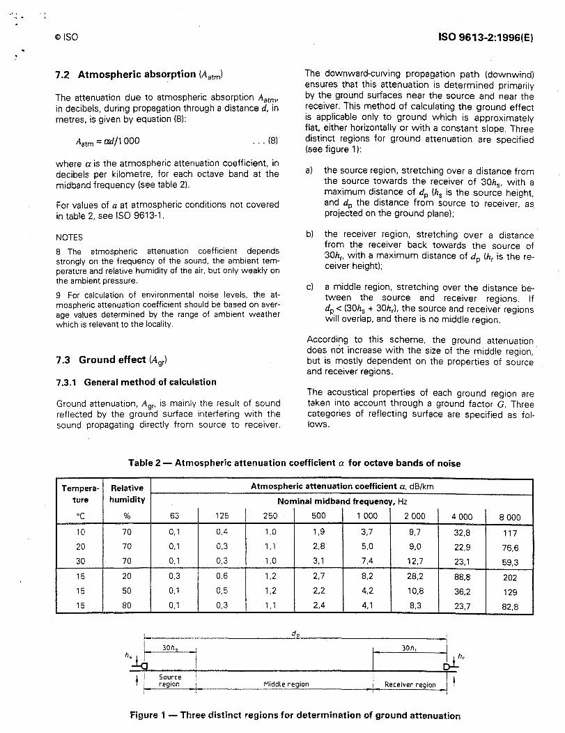
The downward-curving propagation path (downwind) ensures that this attenuation is determined primarily by the ground surfaces near the source and near the receiver. This method of calculating the ground effect is applicable only to ground which is approximately flat, either horizontally or with a constant slope. Three distinct regions for ground attenuation are specified (see figure 1 ):
a) the source region, stretching over a distance from the source towards the receiver of 30h
5, with a
maximum distance of dp (h5 is the source height, and dp the distance from source to receiver, as projected on the ground plane);
b) the receiver region, stretching over a distance from the receiver back towards the source of 30hr, with a maximum distance of dp (hr is the r,eceiver height);
c) a middle region, stretching over the distance between the source and receiver regions. If dp < (30h5 + 30hr). the source and receiver regions will overlap, and there is no middle region.
According to this scheme, the ground attenuation does not increase with the size of the middle region, · but is mostly dependent on the properties of source and receiver regions.
The acoustical properties of each ground region are taken into account through a ground factor G. Three categories of reflecting surface are specified as follows.
Table 2 - Atmospheric attenuation coefficient a for octave bands of noise
Tempera-ture
oc 10
20
30
15 ,,
15
15
Relative humidity
%
70
70
70
20
50
80
63
0, 1
0.1
0,1
0,3
0, 1
0.1
Source region
125
0.4
0,3
0,3
0,6
0,5
0,3
Atmospheric attenuation coefficient a, dB/km
Nominal midband frequency, Hz
250 500 1 000 2 000 4 000
1,0 1,9 3,7 9,7 32,8
1. 1 2,8 5,0 9,0 22,9
1,0 3, 1 7.4 12,7 23,1
1,2 2,7 8,2 28,2 88,8
1,2 2,2 4,2 10,8 36,2
1,1 2.4 4,1 8,3 23,7
30hr
1 · t,t"' Middle region
! I
I
: !
Receiver region / t •I
I
Figure 1 - Three distinct regions for determination of ground attenuation
8 000
117
76,6
59,3
202
129
82,8
ISO 9613-2:1996(E)
a) Hard ground, which includes paving, water, ice, concrete and all other ground surfaces having a low porosity. Tamped ground, for example, as often occurs around industrial sites, can be considered hard. For hard ground G = 0.
NOTE 1 O It should be recalled that inversion conditions over water are not covered by this part of ISO 9613.
bl Porous ground, which includes ground covered by grass, trees or other vegetation, and all other ground surfaces suitable for the growth of vegetation, such as farming land. For porous ground G = 1.
c) Mixed ground: if the surface consists of both hard and porous ground, then G takes on values
al 125 Hz
8
- h = 1.5 m
6 - h = 3.0 m a) ,:,
·,. h = 6.0 m 4
h = 7.5 m
2 h?: 10,0 m
20 50 125 250 500 1000 2 000
Distance dp, m
cl 500 Hz
8
h = 1,5 m
6 a) ,:,
h=1.75m
" 4 h = 2.0 m
h = 2.5 m 2
h?: 3,0 m
20 50 125 250 500 1000 2 000
Distance dp, m
©ISO
ranging from O to 1, the value being the fraction of the region that is porous.
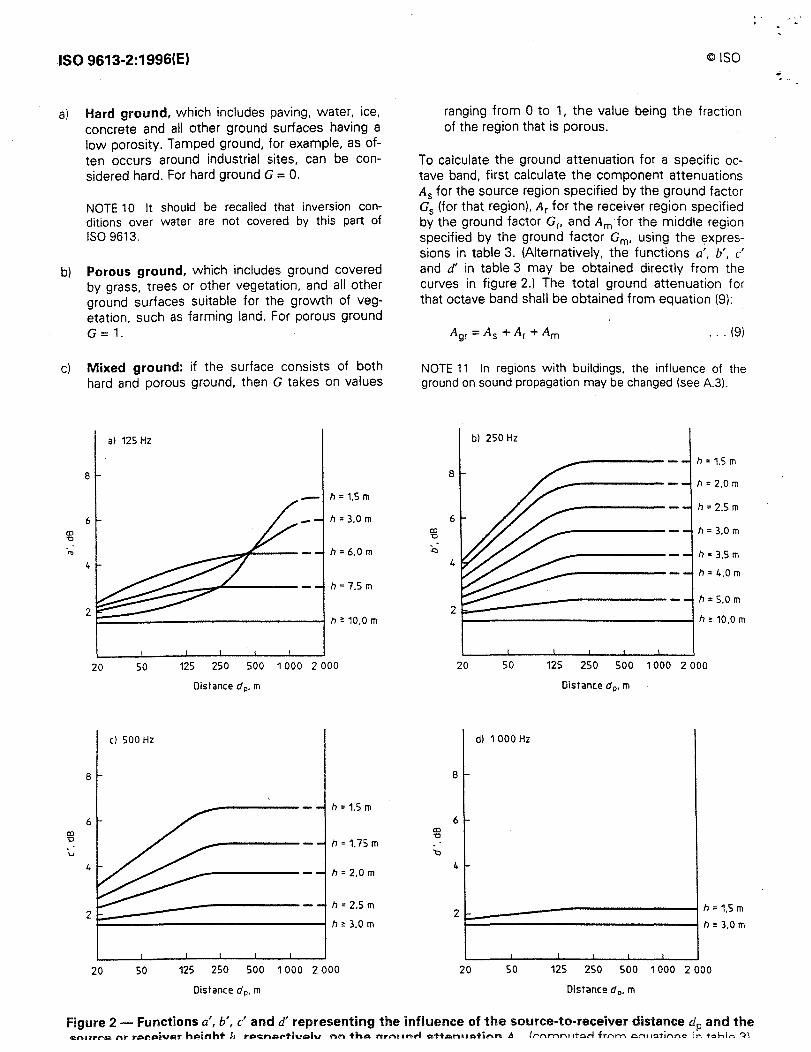
To calculate the ground attenuation for a specific octave band, first calculate the component attenuations As for the source region specified by the ground factor Gs (for that region). Ar for the receiver region specified by the ground factor Gr, and Am for the middle region specified by the ground factor Gm, using the expressions in table 3. (Alternatively, the functions a', b', c' and d' in table 3 may be obtained directly from the curves in figure 2.) The total ground attenuation for that octave band shall be obtained from equation (9):
... (9)
NOTE 11 In regions with buildings, the influence of the ground on sound propagation may be changed (see A.3).
a) ,:,
:.:,
a) ,:,
bl 250 Hz
h = 1.5 m 8
h = 2.0 m
h = 2.5 m 6
h = 3,0 m
h = 3.5 m 4
h = 4.0 m
h = 5.0 m 2
h?: 10,0 m
20 50 125 250 500 1000 2 000
Distance d P• m
d) 1 000 Hz
8 ...
2 k:;...:---------------, h = 1,5 m h"' 3,0 m
I I I I I
20 50 125 250 500 1 000 2 000
Distance d 0 • m
Figure 2 - Functions a', b', c' and d' representing the influence of the source-to-receiver distance dp and the c:n11rro nr rol'oiv1>r hAinht J., roc::nor-tivolu nn th.,, nrn11nrl ""ttcn., .. tinn A /r-,...,rnn1 ,tcrl fr,-,m c,n1 ,<>tir,nc, in T<:>hlo ".)\
©ISO ISO 9613-2:1996(E)
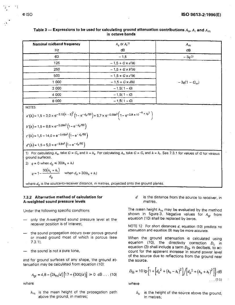
Table 3 - Expressions to be used for calculating ground attenuation contributions A5, Ar and Am in octave bands
Nominal midband frequency As or Ar1l Am
Hz dB dB
63 -1,5 -3q2l
125 - 1,5 + G x a'(h)
250 - 1,5 + G x b'(h)
500 - 1,5 + G x c'(h)
1 000 - 1,5 + G x d(h) -3q(1 - Gm)
2 000 -1,5( 1 - G)
4 000 -1,5( 1 - G)
8 000 -1,5( 1 - G)
NOTES
( )2 ) ( -6 x d 2 ) a'(h)=1,5+3,0xe-0.12h-5 (1-e-dp/50 +5,7xe-0,09h2 1-e-2,8x10 P
b'(h) = 1,5 + 8,6 x e-o.o9h2 (1 - e-dP150 )
c'(h)= 1,5 + 14,0 x e- 0.46h2 (1- e-dp/SO)
d'(lz) = 1,5 + 5,0 x e-O.Sh2 (1 - e-dP150 )
1) For calculating As, take G = G5 and lz = h5 . For calculating Ar, take G =Grand h = hr. See 7.3.1 for values of G for various ground surfaces.
2) q = 0 when dp ~ 30(hs + hrl
q=1-30h +hr)
when dp > 30(h5 + hrl dp
where dp is the source-to-receiver distance, in metres, projected onto the ground planes.
7 .3.2 Alternative method of calculation for A-weighted sound pressure levels
Under the following specific conditions
only the A-weighted sound pressure level at the receiver position is of interest.
the sound propagation occurs over porous ground or mixed ground most of which is porous (see 7.3.1 ),
the sound is not a pure tone,
and for ground surfaces of any shape, the ground attenuation may be calculated from equation (10):
Agr = 4,8 -(2hm/d) [17 + (300/d)] ;.. 0 dB ... (10)
where
hm is the mean height of the propagation path above the ground, in metres;
d is the distance from the source to receiver, in metres.
The mean height hm may be evaluated by the method shown in figure 3. Negative values for Agr from equation (10) shall be replaced by zeros.
NOTE 12 For short distances d, equation (1 O) predicts no attenuation and equation (9) may be more accurate.
When the ground attenuation is calculated using equation ( 10), the directivity correction De in equation (3) shall include a term Dn, in decibels, to account for the apparent increase in sound power level of the source due to reflections from the ground near the source.
Dn = 10 lg {1 + [dl + (h5 -hr )2]/[dl + (h5 + hr )2]} dB
... (11) where
h5 is the height of the source above the ground, in metres;
ISO 9613-2:1996(E)
hr is the height of the receiver above the ground, in metres;
dp is the source-to-receiver distance projected onto the ground plane, in metres.
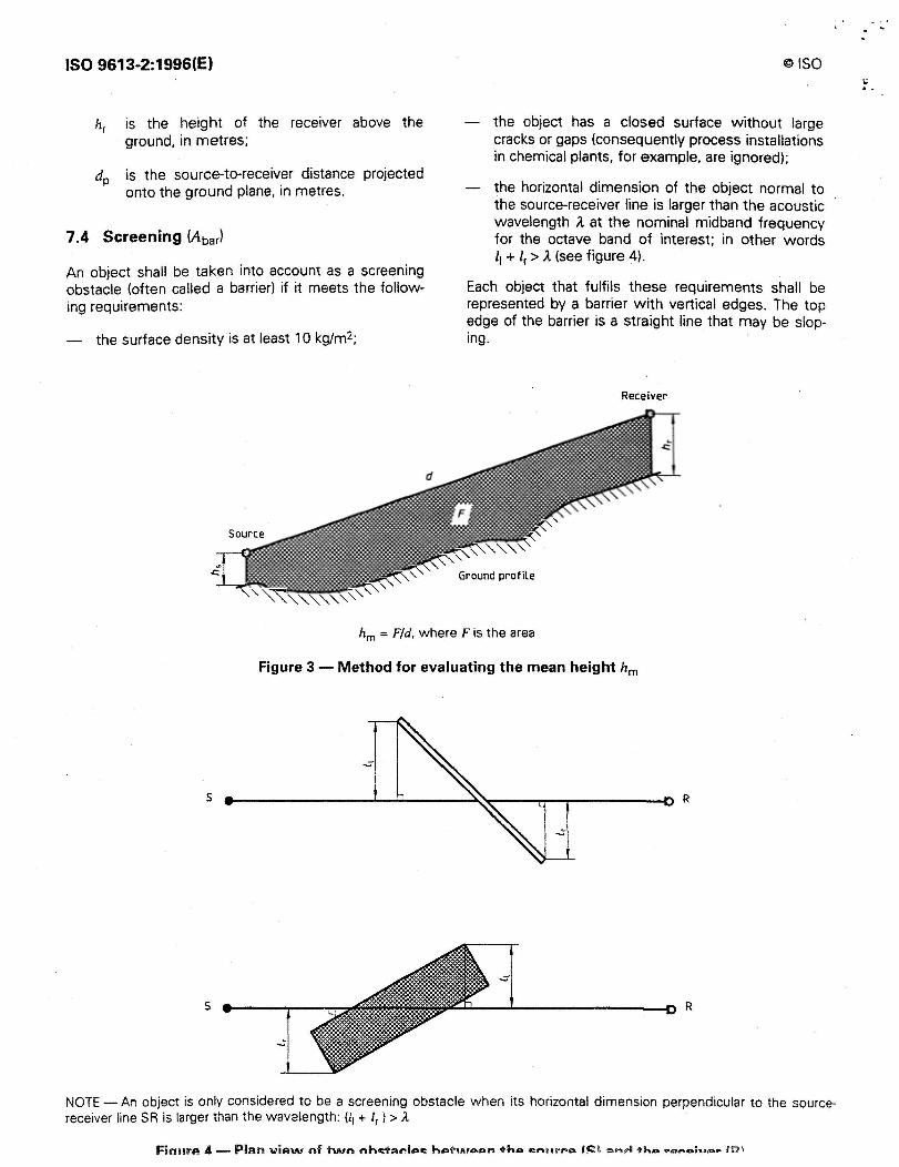
7 .4 Screening (Abarl
An object shall be taken into account as a screening obstacle (often called a barrier) if it meets the following requirements:
- the surface density is at least 10 kg/m2;
@ISO
the object has a closed surface without large cracks or gaps (consequently process installations in chemical plants, for example, are ignored);
the horizontal dimension of the object normal to the source-receiver line is larger than the acoustic wavelength A at the nominal midband frequency for the octave band of interest; in other words 11 + lr > A (see figure 4).
Each object that fulfils these requirements shall be represented by a barrier with vertical edges. The top edge of the barrier is a straight line that may be sloping.
Receiver
Ground profile
hm = F/d. where F is the area
Figure 3 - Method for evaluating the mean height hm
s
s R
NOTE - An object is only considered to be a screening obstacle when its horizontal dimension perpendicular to the sourcereceiver line SR is larger than the wavelength: (11 + lr) > 1
Fin11rP- 4 - Plan v iP-'IN nf t'INn nhc::hu•I ,: .. : h o-t\Aloon ♦ho cn11rl'A f~ \ D n~ +h .. • .,.,.,.;.,,.. ID !
. ' . @ISO
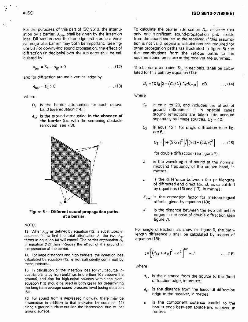
For the purposes of this part of ISO 9613, the attenuation by a barrier, Abar- shall be given by the insertion loss. Diffraction over the top edge and around a vertical edge of a barrier may both be important. (See figure 5.) For downwind sound propagation, the effect of diffraction (in decibels) over the top edge shall be calculated by
... (12)
and for diffraction around a vertical edge by
... (13)
where
Dz is the barrier attenuation for each octave band [see equation (14)];
Agr is the ground attenuation in the absence of the barrier (i.e. with the screening obstacle removed) (see 7.3).
R
Figure 5 - Different sound propagation paths at a barrier
NOTES
13 When Abar as defined by equation (12) is substituted in equation (4) to find the total attenuation A, the two A9, terms in equation (4) will cancel. The barrier attenuation D2
in equation (12) then includes the effect of the ground in the presence of the barrier.
14. For large distances and high barriers, the insertion loss calculated by equation (12) is not sufficiently confirmed by measurements.
15 In calculation of the insertion loss for multisource industrial plants by high buildings (more than 1 O m above the ground), and also for high-noise sources within the plant, equation (13) should be used in both cases for determining the long-term average sound pressure level [using equation (6)).
16 For sound from a depressed highway, there may be attenuation in addition to that indicated by equation (12) along a ground surface outside the depression. due to that ground surface.
ISO 9613-2:1996(E)
To calculate the barrier attenuation Dz, assume that only one significant sound-propagation path exists from the sound source to the receiver. If this assumption is not valid, separate calculations are required for other propagation paths (as illustrated in figure 5) and the contributions from the various paths to the squared sound pressure at the receiver are summed.
The barrier attenuation Dz, in decibels, shall be calculated for this path by equation (14):
... (14)
where
C2 is equal to 20, and includes the effect of ground reflections; if in special cases ground reflections are taken into account separately by image sources, c2 = 40;
c3 is equal to 1 for single diffraction (see figure 6);
for double diffraction (see figure 7);
il is the wavelength of sound at the nominal midband frequency of the octave band, in metres;
z is the difference between the pathlengths of diffracted and direct sound, as calculated by equations (16) and (17), in metres;
Kmet is the correction factor for meteorological effects, given by equation (18);
e is the distance between the two diffraction edges in the case of double diffraction (see figure 7).
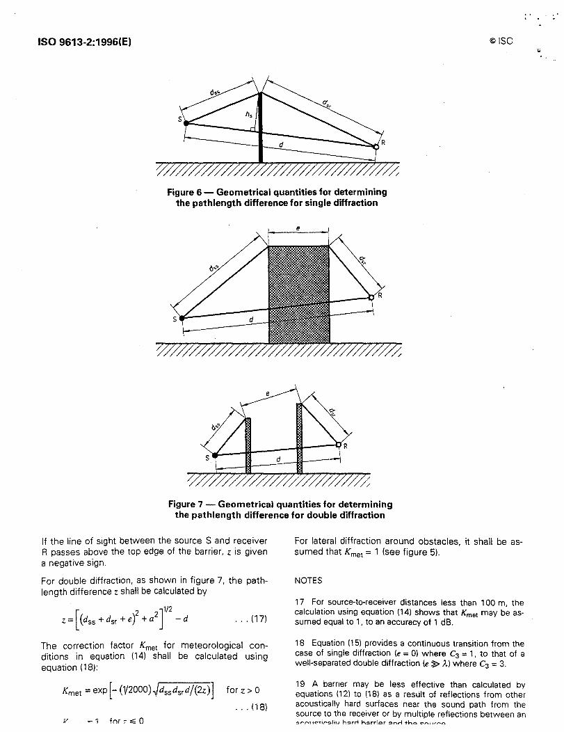
For single diffraction, as shown in figure 6, the pathlength difference z shall be calculated by means of equation (16):
[ 2 ]1/2
z = (dss + dsr) + a2 - d ... (16)
where
d55 is the distance from the source to the (first) diffraction edge, in metres;
d5r is the distance from the (second) diffraction edge to the receiver, in metres;
a is the component distance parallel to the barrier edge between source and receiver, in metres.
ISO 9613-2:1996(E) ©ISO
Figure 6 - Geometrical quantities for determining the pathlength difference for single diffraction
Figure 7 - Geometrical quantities for determining the pathlength difference for double diffraction
If the line of sight between the source S and receiver R passes above the top edge of the barrier, z is given a negative sign.
For double diffraction, as shown in figure 7, the pathlength difference z shall be calculated by
[ 2 2]
112 z = (d55 + d5r + e) + a - d ... (17)
The correction factor Kmet for meteorological conditions in equation (14) shall be calculated using equation (18):
Y = 1 fnr 7,;;; 0
for z > O
... (18)
For lateral diffraction around obstacles, it shall be assumed that Kmet = 1 (see figure 5).
NOTES
17 For source-to-receiver distances less than 100 m, the calculation using equation (14) shows that Kmet may be assumed equal to 1, to an accuracy of 1 dB.
18 Equation (15) provides a continuous transition from the case of single diffraction (e = 0) where c3 = 1, to that of a well-separated double diffraction (e ~ ;\.) where c3 = 3.
19 A barrier may be less effective than calculated by equations (12) to (18) as a result of reflections from other acoustically hard surfaces near the sound path from the source to the receiver or by multiple reflections between an '!:lf"'f'\1 teti,-.'!llh, h~rrl h~rrior '!lnrl -tho c:-r\l ,r,.....o
"'
©ISO
The barrier attenuation D2, in any octave band, should not be taken to be greater than 20 dB in the case of single diffraction (i.e. thin barriers) and 25 dB in the case of double diffraction (i.e. thick barriers).
The barrier attenuation for two barriers is calculated using equation ( 14) for double diffraction, as indicated in the lower part of figure 7. The barrier attenuation for more than two barriers may also be calculated approximately using equation (14). by choosing the two most effective barriers, neglecting the effects of the others.
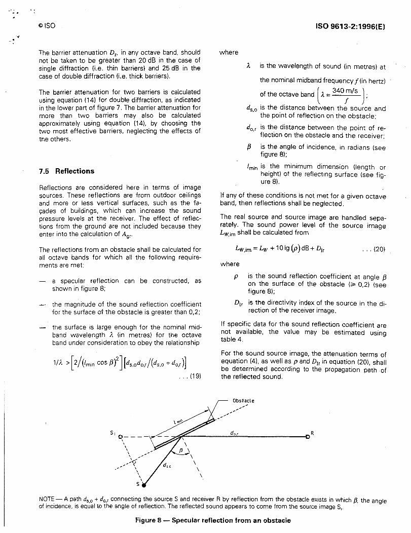
7 .5 Reflections
Reflections are considered here in terms of image sources. These reflections are from outdoor ceilings and more or less vertical surfaces, such as the fa<;ades of buildings, which can increase the sound pressure levels at the receiver. The effect of reflections from the ground are not included because they enter into the calculation of Agr·
The reflections from an obstacle shall be calculated for all octave bands for which all the following requirements are met:
a specular reflection can be constructed, as shown in figure 8;
the magnitude of the sound reflection coefficient for the surface of the obstacle is greater than 0,2;
the surface is large enough for the nominal midband wavelength A (in metres) for the octave band under consideration to obey the relationship
1/A >[2/(tmin cosf3)2][ds,odo,r/(ds,o +do.r)]
S; e,,- - - -
\ \ \
\ \ \ ,
\ ,' ,,,.,,,..,.,,,.? ., \
\ \
\
s
... (19)
where
ISO 9613-2:1996(E)
A is the wavelength of sound (in metres) at
the nominal midband frequency f (in hertz)
of the octave band l A= 340
;/s ) ;
d5 ,0 is the distance between the source and the point of reflection on the obstacle;
d0 ,r is the distance between the point of reflection on the obstacle and the receiver;
/3 is the angle of incidence, in radians (see figure 8);
lmin is the minimum dimension (length or height) of the reflecting surface (see figure 8).
If any of these conditions is not met for a given octave band, then reflections shall be neglected.
The real source and source image are handled separately. The sound power level of the source image Lw,im shall be calculated from
Lw,im = Lw + 10 lg (p) dB+ D1r ... (20)
where
p is the sound reflection coefficient at angle /3 on the surface of the obstacle (;;;. 0,2) (see figure 8);
D1r is the directivity index of the source in the di-rection of the receiver image.
If specific data for the sound reflection coefficient are not available, the value may be estimated using table 4.
For the sound source image, the attenuation terms of equation (4). as well as p and D1r in equation (20). shall be determined according to the propagation path of the reflected sound.
Obstacle
NOTE - A path d5,0 + d0 ,r connecting the source S and receiver R by reflection from the obstacle exists in which /3. the angle of incidence, is equal to the angle of reflection. The reflected sound appears to come from the source images,.
figure 8 - Specular reflection from an obstacle
ISO 9613-2:1996(E) ©ISO
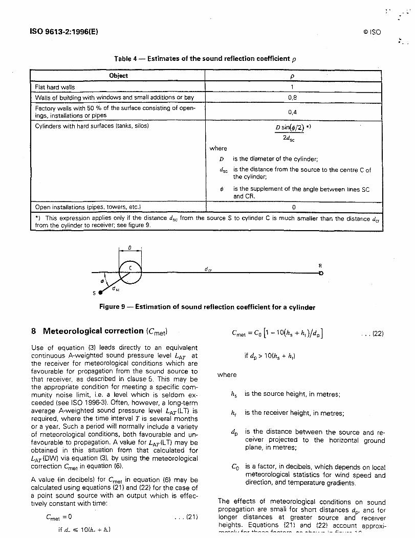
Table 4 - Estimates of the sound reflection coefficient p
Object p
Flat hard walls 1
Walls of building with windows and small additions or bay 0,8
Factory walls with 50 % of the surface consisting of open-0,4
ings, installations or pipes
Cylinders with hard surfaces (tanks, silos) D sin(lf>/2) *> 2dsc
where
D is the diameter of the cylinder;
dsc is the distance from the source to the centre C of the cylinder;
"' is the supplement of the angle between lines SC and CR.
Open installations (pipes, towers, etc.) 0
*) This expression applies only if the distance dsc from the source S to cylinder C is much smaller than the distance dcr from the cylinder to receiver; see figure 9.
0
R
s
Figure 9 - Estimation of sound reflection coefficient for a cylinder
8 Meteorological correction (Cmet)
Use of equation (3) leads directly to an equivalent continuous A-weighted sound pressure level LAT at the receiver for meteorological conditions which are favourable for propagation from the sound source to that receiver, as described in clause 5. This may be the appropriate condition for meeting a specific community noise limit, i.e. a level which is seldom exceeded (see ISO 1996-3). Often, however, a long-term average A-weighted sound pressure level LAT(L T) is required, where the time interval T is several months or a year. Such a period will normally include a variety of meteorological conditions, both favourable and unfavourable to propagation. A value for LAT (LT) may be obtained in this situation from that calculated for LAT (DW) via equation (3), by using the meteorological correction Cmet in equation (6).
A value (in decibels) for Cmet in equation (6) may be calculated using equations (21) and (22) for the case of a point sound source with an output which is effectively constant with time:
Cmet =0 ... (21)
if d_ =s;; 1 O(h_ + h.)
... (22)
where
h5 is the source height, in metres;
hr is the receiver height, in metres;
dp is the distance between the source and receiver projected to the horizontal ground plane, in metres;
C0 is a factor, in decibels, which depends on local meteorological statistics for wind speed and direction, and temperature gradients.
The effects of meteorological conditions on sound propagation are small for short distances dp, and for longer distances at greater source and receiver heights. Equations (21) and (22) account approxi-.................... ,., ,_.,. +L-.-. ..... ,,.., ♦ ..... ,,.. ............... -- -.L..-.. - ·- :- .£: __ --- .. I"'\
.. .
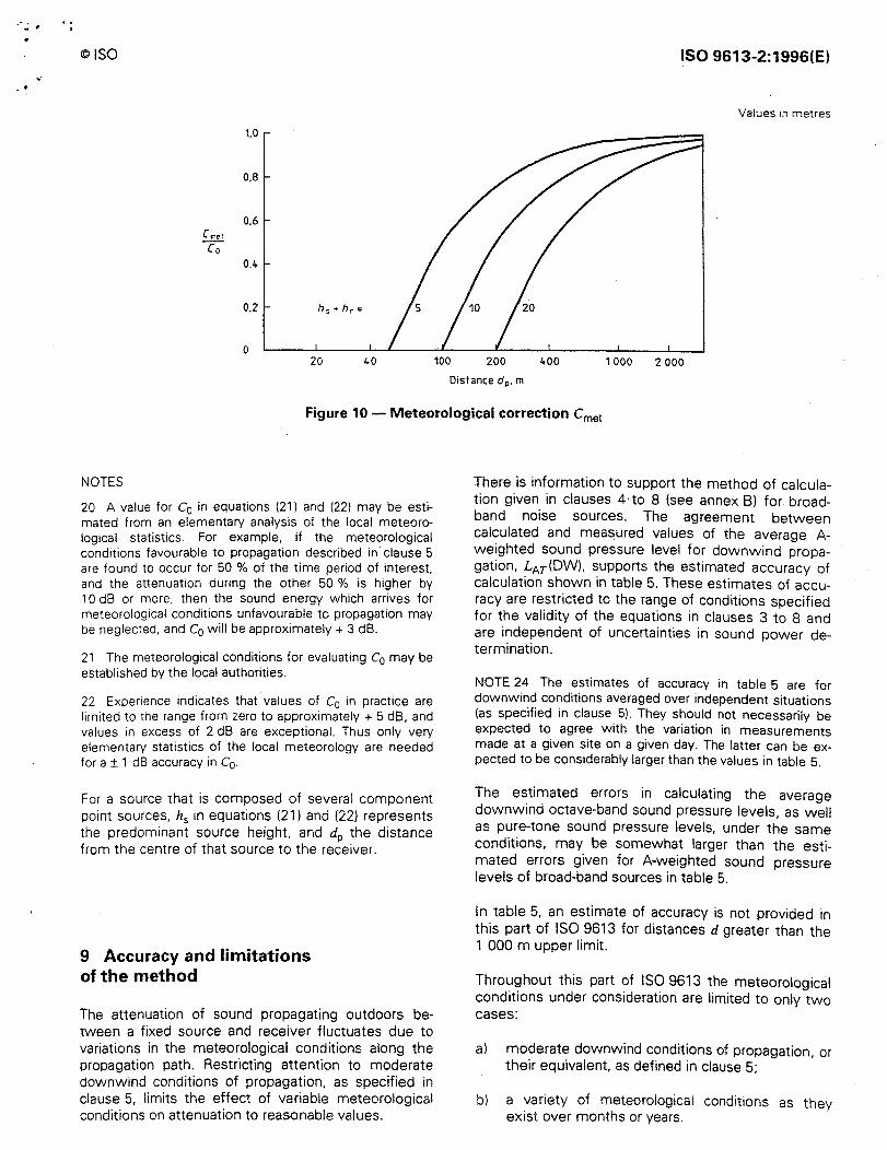
©ISO ISO 9613-2:1996(E)
Values 1n metres
1.0
0,8
0,6 Cmet
Ca 0,4
0,2 h, +hr=
0 20 40 100 200 400 1 000 2 000
Distance dp, m
Figure 10- Meteorological correction Cmet
NOTES
20 A value for c0 in equations (21) and (22) may be estimated from an elementary analysis of the local meteorological statistics. For example. if the meteorological conditions favourable to propagation described in clause 5 are found to occur for 50 % of the time period of interest. and the attenuation during the other 50 % is higher by 1 O dB or more. then the sound energy which arrives for meteorological conditions unfavourable to propagation may be neglected. and Co will be approximately + 3 dB.
21 The meteorological conditions for evaluating Co may be established by the local authorities.
22 Experience indicates that values of C0 in practice are limited to the range from zero to approximately + 5 dB. and values in excess of 2 dB are exceptional. Thus only very elementary statistics of the local meteorology are needed for a ± 1 dB accuracy in C0.
For a source that is composed of several component point sources, lz5 in equations (21) and (22) represents the predominant source height, and dp the distance from the centre of that source to the receiver.
9 Accuracy and limitations of the method
The attenuation of sound propagating outdoors between a fixed source and receiver fluctuates due to variations in the meteorological conditions along the propagation path. Restricting attention to moderate downwind conditions of propagation, as specified in clause 5, limits the effect of variable meteorological conditions on attenuation to reasonable values.
There is information to support the method of calculation given in clauses 4·to 8 (see annex B) for broadband noise sources. The agreement between calculated and measured values of the average Aweighted sound pressure level for downwind propagation, LAr(DW). supports the estimated accuracy of calculation shown in table 5. These estimates of accuracy are restricted to the range of conditions specified for the validity of the equations in clauses 3 to 8 and are independent of uncertainties in sound power determination.
NOTE 24 The estimates of accuracy in table 5 are for downwind conditions averaged over independent situations (as specified in clause 5). They should not necessarily be expected to agree with the variation in measurements made at a given site on a given day. The latter can be expected to be considerably larger than the values in table 5.
The estimated errors in calculating the average downwind octave-band sound pressure levels, as well as pure-tone sound pressure levels, under the same conditions, may be somewhat larger than the estimated errors given for A-weighted sound pressure levels of broad-band sources in table 5.
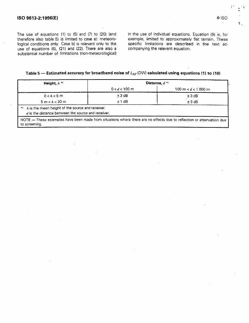
In table 5, an estimate of accuracy is not provided in this part of ISO 9613 for distances d greater than the 1 000 m upper limit.
Throughout this part of ISO 9613 the meteorological conditions under consideration are limited to only two cases:
al moderate downwind conditions of propagation, or their equivalent, as defined in clause 5;
bl a variety of meteorological conditions as they exist over months or years.
ISO 9613-2:1996(E)
The use of equations (1) to (5) and (7) to (20) (and therefore also table 5) is limited to case a): meteorological conditions only. Case b) is relevant only to the use of equations (6), (21) and (22). There are also a substantial number of limitations (non-meteorological)
©ISO
in the use of individual equations. Equation (9) is, for example, limited to approximately flat terrain. These specific limitations are described in the text accompanying the relevant equation.
Table 5 - Estimated accuracy for broadband noise of LAr(DW) calculated using equations (1) to (10)
Height, h *1 Distance, d •i
0 <d< 100 m 1 00 m < d < 1 000 m
0<h<5m ±3 dB ±3 dB
5 m < h <30 m ± 1 dB ±3 dB •) h is the mean height of the source and receiver.
d is the distance between the source and receiver.
NOTE - These estimates have been made from situations where there are no effects due to reflection or attenuation due to screening.
- ..
.
©ISO ISO 9613-2:1996(E)
Annex A (informative)
Additional types of attenuation (Amisd
The term Amisc in equation (4) covers contributions to the attenuation from miscellaneous effects not accessible by the general methods of calculating the attenuation specified in clause 7. These contributions include
A101 , the attenuation of sound during propagation through foliage,
Asite• the attenuation during propagation through an industrial site, and
Ahaus• the attenuation during propagation through a built-up region of houses,
which are all considered in this annex.
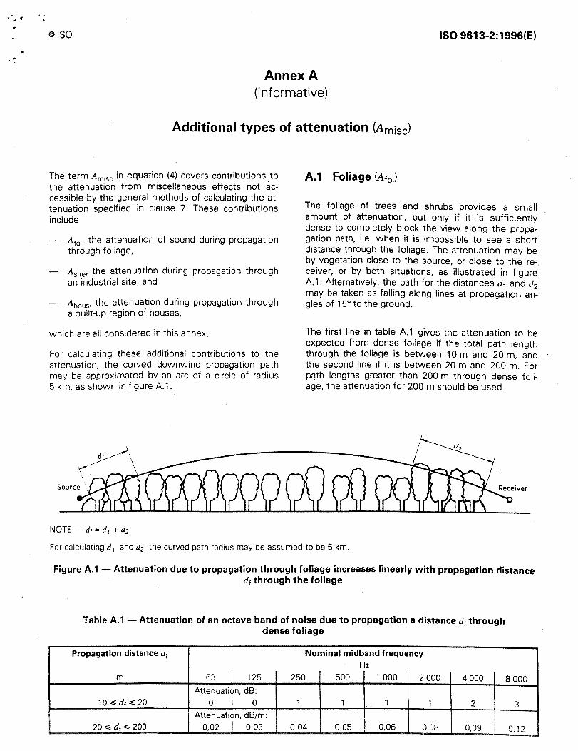
For calculating these additional contributions to the attenuation, the curved downwind propagation path may be approximated by an arc of a circle of radius 5 km, as shown in figure A.1.
NOTE -di= d1 + d2
A.1 Foliage (Afo1)
The foliage of trees and shrubs provides a small amount of attenuation, but only if it is sufficiently dense to completely block the view along the propagation path, i.e. when it is impossible to see a short distance through the foliage. The attenuation may be by vegetation close to the source, or close to the re-, ceiver, or by both situations, as illustrated in figure A.1. Alternatively, the path for the distances d1 and d2 may be taken as falling along lines at propagation angles of 15° to the ground.
The first line in table A.1 gives the attenuation to be expected from dense foliage if the total path length through the foliage is between 1 0 m and 20 m, and the second line if it is between 20 m and 200 m. For pc3th lengths greater than 200 m through dense foliage, the attenuation for 200 m should be used.
For calculating d1 and d2, the curved path radius may be assumed to be 5 km.
Figure A.1 - Attenuation due to propagation through foliage increases linearly with propagation distance d1 through the foliage
Table A.1 - Attenuation of an octave band of noise due to propagation a distance dt through dense foliage
Propagation distance di Nominal midband frequency Hz
m 63 I 125 250 500 1 000 2 000 4 000
Attenuation, dB: 10..; d1 ..; 20 0 I 0 1 1 1 1 2
Attenuation, dB/m: 20..; d1.;; 200 0,02 I 0,03 0,04 0,05 0,06 0,08 0,09
8 000
3
0,12
ISO 9613-2:1996(E}
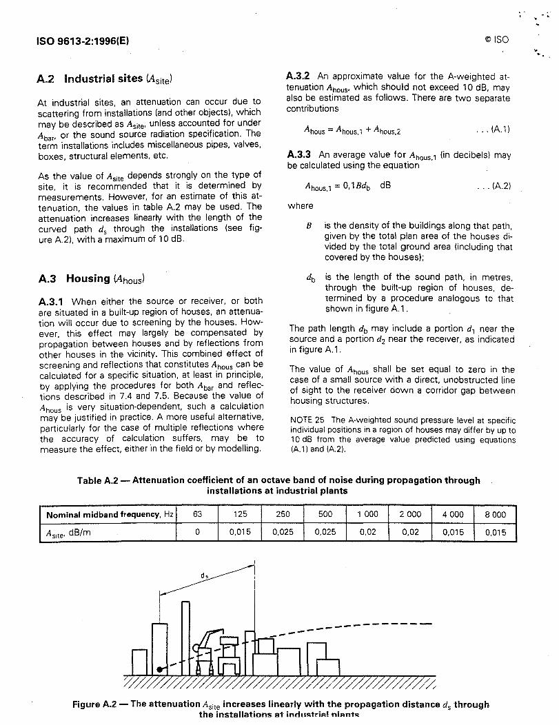
A.2 Industrial sites (Asitel
At industrial sites, an attenuation can occur due to scattering from installations (and other objects), which may be described as Asite• unless accounted for under Abar• or the sound source radiation specification. The term installations includes miscellaneous pipes, valves, boxes, structural elements, etc.
As the value of Asite depends strongly on the type of site, it is recommended that it is determined by measurements. However, for an estimate of this attenuation, the values in table A.2 may be used. The attenuation increases linearly with the length of the curved path ds through the installations (see figure A.2), with a maximum of 10 dB.
A.3 Housing (Ahousl
A.3.1 When either the source or receiver, or both are situated in a built-up region of houses, an attenuation will occur due to screening by the houses. However, this effect may largely be compensated by propagation between houses and by reflections from other houses in the vicinity. This combined effect of screening and reflections that constitutes Ahaus can be calculated for a specific situation, at least in principle, by applying the procedures for both Abar and reflections described in 7.4 and 7.5. Because the value of Ahaus is very situation-dependent, such a calculation may be justified in practice. A mor~ useful alternative, particularly for the case of multiple reflections where the accuracy of calculation suffers, may be to measure the effect, either in the field or by modelling.
©ISO
A.3.2 An approximate value for the A-weighted attenuation Ahaus• which should not exceed 1 O dB, may also be estimated as follows. There are two separate contributions
... (A.1)
A.3.3 An average value for Ahaus., (in decibels) may be calculated using the equation
Ahaus, 1 = 0, 1 Bdb dB
where
... (A.2)
B is the density of the buildings along that path, given by the total plan area of the houses divided by the total ground area (including that covered by the houses);
db is the length of the sound path, in metres, through the built-up region of houses, determined by a procedure analogous to that shown in figure A.1 .
The path length db may include a portion d1 near the source and a portion d2 near the receiver, as indicated in figure A.1 .
The value of Ahaus shall be set equal to zero in the case of a small source with a direct, unobstructed line of sight to the receiver down a corridor gap betw~en housing structures.
NOTE 25 The A-weighted sound pressure level at specific individual positions in a region of houses may differ by up to 10 dB from the average value predicted using equations (A.1) and (A.2).
Table A.2 - Attenuation coefficient of an octave band of noise during propagation through installations at industrial plants
Nominal midband frequency, Hz 63 125 250 500 1 000 2 000 4 000 8 000
Asite• dB/m 0 0,015 0,025 0,025 0,02 0,02 0,015 0,015
-------------
1/✓
Figure A.2 - The attenuation Asite increases linearly with the propagation distanced through the installations at industrial nlants
5
•
•
©ISO
A.3.4 If there are well-defined rows of buildings near a road, a railway, or a similar corridor, an additional term Ahous,2 may be included (provided this term is less than the insertion loss of a barrier at the same position with the mean height of the buildings):
Ahous,2 = - 10 lg[1 - (p/100)] dB ... (A.3)
where p (the percentage of the length of the fac;ades relative to the total length of the road or railway in the vicinity) is :s;:; 90 % .
A.3.5 In a built-up region of houses, the value of Ahous., [as calculated by equation (A.2)] interacts as follows with the value for A9r, the attenuation due to
ISO 9613-2:1996(E)
the ground las calculated by equation (9) or equation (10)].
Let A9r,b be the ground attenuation in the built-up region, and A9r,o be the ground attenuation if the houses were removed [i.e. as calculated by equation (9) or equ~tion (10)]. For propagation through the built-up region in general, A9r,b is assumed to be zero in equation (4). If, however, t~e value of Agr,o is greater than that of Ahous• then the influence of Aho is ignored and only the value of A9r,o is included in eq~~tion (4).
The interaction above is essentially to allow for a range of housing density B. For low-density housing, the value of A9r is dominant, while for high-density housing Ahous dominates.
ISO 9613-2:1996(E) ©ISO
Annex B (informative)
Bibliography
[1 l ISO 266:- 1), Acoustics - Preferred frequencies.
(21 ISO 2204:1979, Acoustics - Guide to International Standards on the measurement of airborne acoustical noise and evaluation of its effect on human beings.
[3] ISO 3740:1980, Acoustics - Determination of sound power levels of noise sources - Guidelines for the use of basic standards and for the preparation of noise test codes.
[4] ISO 3744: 1994, Acoustics - Determination of sound power levels of noise sources using sound pressure - Engineering method in an essentially free field over a reflecting plane.
15] ISO 8297:1994, Acoustics - Determination of sound power levels of multisource industrial plants for the evaluation of sound-pressure levels in the environment - Engineering method.
16] IEC 804:1985, Integrating averaging sound level meters, and Amendment 1: 1989 and Amendment 2:1993.
[7] I EC 1260: 1995, Electroacoustics - Octave-band and fractional-octave-band filters.
18] ANSI S1 .26:1978, Method for the calculation of the absorption of sound by the atmosphere. (American national standard)
[9] BRACKENHOFF H.E.A. et al. Guidelines for the measurement and prediction of environmental noise from industry. Interdepartmental Commission on Health, Report HR-IL-13-01, Delft, April 1981. (In Dutch)
11 O] KRAGH J. et al. Environmental Noise from Industrial Plants: General Prediction Method. Danish Acoustical Institute Report No. 32, Lyngby, 1982. (In English)
111] VDI 2714:1988, Guidelines: Sound propagation outdoors. Verein Deutscher lngenieure. (In German)
[12] VDI 2720-1:1996, Guidelines: Outdoor noise control by means of screening. Verein Deutscher lngenieure. (In German)
(13] Engineering Equipment Material Users Association, Publication 140, London, 1985.

• •

. . ',-l
" ISO 9613-2:1996(E} ©ISO
ICS 17.140.01 Descriptors: acoustics, noise !sound). airborne sound. wave propagation, attenuation, rules ot calculation.