Embed Size (px)
Citation preview

AcquiLite – Data Acquisition ServerObvius, LLC
Installation and Operation Manual
Model A7801
Date Jun 21, 2010
Page 1 A7801 AcquiLite – Data Acquisition Server

Copyright InformationCopyright © 2003 - 2010 by Obvius
Obvius and AcquiLite are trademarks of Obvius Holdings LLcOther brand and product names are trademarks or registered trademarks of their respective holders.
U.S. Government Restricted Rights: Use, duplication or disclosure by the Government is subject to restrictions set fourth in subparagraph (a) through (d) of the Commercial Computer Restricted Rights clause at FAR 52.227-19 when applicable, or subparagraph (c) (1) (ii) of the Rights in Technical Data and Computer Software clause at DFARS 252.227-7013, and in similar clauses in the NASA FAR Supplement.
Limited WarrantyOBVIUS IS PROVIDING THIS WARRANTY IN LIEU OF ALL OTHER EXPRESS OR IMPLIED WARRANTIES, INCLUDING ANY WARRANTY OF MERCHANTABILITY OR FITNESS FOR A PARTICULAR PURPOSE. THIS WARRANTY IS BUYER'S EXCLUSIVE REMEDY FOR ALL CLAIMS AGAINST OBVIUS. OBVIUS SHALL NOT BE LIABLE FOR ANY CONSEQUENTIAL OR INCIDENTAL DAMAGES. OBVIUS'S TOTAL LIABILITY FOR ALL CLAIMS SHALL BE LIMITED TO THE PRICE PAID FOR ITS PRODUCT.
Obvius promises buyer that any standard product manufactured by Obvius shall be free from all material defects in design, material, or manufacturing for a period of 2 years from the manufacture date; provided, however, that the warranty shall not extend to ordinary wear and tear or to normally replaceable components (e.g., batteries). During the warranty period, Obvius may repair or replace (in its sole discretion) any product suffering from a warranty defect and returned freight prepaid by buyer, with no charge to buyer for any warranty repair or replacement. The warranty shall remain in full force and effect for such 2 year period, provided that the product: (1) was installed, operated, and maintained properly; (2) has not been abused or misused; (3) has not been repaired, altered, or modified outside of Obvius's authorized facilities; (4) has not been sold subject to other warranty terms specified at the time of sale; and (5) is still owned by the original purchaser. This warranty provides specific legal rights that may be varied by state law. Obvius's products are not designed for life or safety applications.
Product Application LimitationObvius products are not intended for use in critical applications such as nuclear facilities, human implantable devices or life support. Obvius is not liable, in whole or in part, for any claims or damages arising from such uses.
Obvius strongly believes in continuous improvement, therefore we must reserve the right to change specifications and product offerings without notice. Where possible, we will substitute products with equivalent functionality when necessary.
NOTICE This product is not intended for life safety applications. Do not install this product in hazardous or classified locations. The installer is responsible for conformance to all applicable codes.
FCC Part 15 Information
Note: This equipment has been tested by the manufacturer and found to comply with the limits of a class A digital device, pursuant to part 15 of the FCC rules. These limits are designed to provide reasonable protection against interference when the equipment is operated in a commercial environment. This equipment generates, uses, and can radiate radio frequency energy and, if not installed and used in accordance with the instruction manual, may cause harmful interference to radio communications. Operation of this equipment in a residential area is likely to cause harmful interference in which case the user will be required to correct the interference at his own expense. Modifications of this product without the express authorization of Obvius nullify this statement.
Obvius3300 NW 211th TerraceHillsboro, OR 97007ph: 503-601-2099www.obvius.com
Page 2 A7801 AcquiLite – Data Acquisition Server
Table of ContentsOverview......................................................................................................................................................................................4Installation Checklist...................................................................................................................................................................4Hardware Overview.....................................................................................................................................................................5
A7801 Features and Specifications........................................................................................................................................5Electrical Connections...........................................................................................................................................................6Hardware Installation.............................................................................................................................................................6
Basic Network Configuration......................................................................................................................................................7Laptop/Computer Setup.........................................................................................................................................................8
AcquiLite Administration Overview............................................................................................................................................9Security......................................................................................................................................................................................10Logger........................................................................................................................................................................................11
Pulse Inputs - Status.............................................................................................................................................................11Pulse Input ...........................................................................................................................................................................13Pulse Input Rate configuration.............................................................................................................................................13
Pulse Grouping ..............................................................................................................................................................14Logger Setup........................................................................................................................................................................14
Networking................................................................................................................................................................................15Network Status.....................................................................................................................................................................15Ethernet setup.......................................................................................................................................................................15Troubleshooting Ethernet Problems.....................................................................................................................................16Modem Setup.......................................................................................................................................................................16Modem PPP Dialout............................................................................................................................................................16Example Dialout to an ISP or RAS......................................................................................................................................16Modem PPP Dialin...............................................................................................................................................................17Example Dialin from a Win98/ME computer......................................................................................................................17Example Dialin from a WinXP computer............................................................................................................................18
System Options..........................................................................................................................................................................19Status....................................................................................................................................................................................19Processes..............................................................................................................................................................................19Date and Time......................................................................................................................................................................19
Universal Time Is Your Friend.......................................................................................................................................20System logs..........................................................................................................................................................................20
Diagnostics ...............................................................................................................................................................................21Connection Test...................................................................................................................................................................21
LCD Console.............................................................................................................................................................................21Log File Data.............................................................................................................................................................................23
Log File Status.....................................................................................................................................................................23Log File Format....................................................................................................................................................................23Log Storage Capacity...........................................................................................................................................................24Uploading data to the BMO website....................................................................................................................................24
Retrieving Data From the AcquiLite........................................................................................................................................25HTTP Direct from the AcquiLite.........................................................................................................................................25HTTP/Post Upload To Building Manager Online...............................................................................................................25HTTP/Post Upload To Your Database Server.....................................................................................................................25Enertrax download direct from the AcquiSuite....................................................................................................................25Removing Data From the AcquiLite....................................................................................................................................25Linking to AcquiLite Device Status Pages...........................................................................................................................26
Firmware Update.......................................................................................................................................................................26
Page 3 A7801 AcquiLite – Data Acquisition Server
OverviewThe AcquiLite™ data acquisition system is designed to allow owners and managers of commercial and industrial facilities with a cost-effective means of gathering crucial information in a timely manner. To meet these requirements, the AcquiLite™ system provides the installer with all the tools necessary to install and configure the hardware and software with a minimum of time and investment.
Installation ChecklistAn AcquiLite™ system installation has the following components:
Required hardware
AcquiLite™ A7801-1 Data Acquisition Server (required) Data connection (ethernet or phone line).
Ethernet Cat 5 cable (required for connection to existing Local Area Network); or Ethernet Cat 5 Crossover cable (required for direct laptop-to-AcquiLite connection); or Phone line and cord (required for modem connection)
External hardware
Pulse output transducers for measuring gas, electricity, water, etc. from existing meters and sensors. Make sure to obtain the pulse output scale, or multiplier for each device you will be using.
Next, choose one or more of the following connection methods.
For LAN installations only:
Ethernet 10Mbit half-duplex connection point (hub or switch) IP, Netmask, gateway, and DNS addresses (check with system administrator) HTTP Proxy address (optional), may be required if the AcquiLite is behind a firewall (check with system
administrator)
For dialout installations only: (AcquiLite initiates a phone call to your ISP or modem server)
Phone line with dialtone. May be shared with other devices such as a fax machine. Phone cord for connection to phone system Dial out access prefixes, and long distance access code if required. (ie, dial 9 for local line) Internet dialup account or Modem Server phone number (check with ISP) Time to dial. If phone line is shared, choose a time of day when other devices are not in use, such as 4am. A regular telephone for line testing and diagnostics
For dialin installations only: (AcquiLite receives/answers a phone call from your computer)
Phone line with dialtone. Must be NOT shared with other devices. (or use appropriate line sharing device) Phone cord for connection to phone system. Telephone number for the phone line that the AcquiLite will be attached to. (so you can call the AcquiLite) Make note of the AcquiLite dialin IP/Netmask for future use. A regular telephone for line testing and diagnostics
Page 4 A7801 AcquiLite – Data Acquisition Server

Hardware Overview
A7801 Features and SpecificationsProcessor R2000 - 8bit embedded cpu, 22Mhz.Memory 512K flash, 512k sram.LED 4x pulse input, 4x modem activity, power, alive, Ethernet link/actConsole 2 x 16 LCD (passive), two pushbuttonsLAN 10base-T Ethernet, half duplexModem V.34 bis, 33,600 bpsProtocols TCP/IP, PPP, HTTP/HTML, NTPPower Supply 9-12VDC, 500mA, class 2 wall brick transformer.
North America: 110-120VAC, 60hz, primary. (standard, included)Interval Recording User selectable 1-60 minutes. Default 15 minute intervalInputs1
Pulse Inputs 4 pulse count inputs intended for use with dry contact outputs. (consumption/rate/runtime/status) Standard and KYZ modes for form A and C relay outputsMaximum rate: 10hz, minimum pulse width 50msContact closure threshold: 600Ω
Utility sync input 1x input intended for use with dry contact output.Environmental North America: Indoor, temperature 0º - 50ºc, 0 - 95% humidity, non-condensing. Size 8” x 9.25” x 2.5”
1 inputs are intended for low voltage class 2 outputs.
2 if the product is used in a manner not specified by the manufacture, the protection provided by the equipment may be impaired.
Page 5 A7801 AcquiLite – Data Acquisition Server

Electrical Connections
Hardware InstallationStep 1 - Unpack materials: Remove all materials from shipping box and verify all required components are available
Step 2 - Mount the AcquiLite on the wall or other appropriate location.
Step 3 - Connect the pulse output devices. For KYZ pulse output meters, attach the normally-open circuit to the AcquiLite. These are usually the K and Z terminals. Note: if the meter is a true KYZ meter (form C) you must check the kyz checkbox in the pulse input configuration page. Please refer to the pulse input section of this document for further details.
A special Sync Input contact closure input is provided for "End of demand interval" signal from the utility or other source. When this contact is closed, the AcquiLite will immediately begin a log cycle and record data for each meter. Using this pulse input will override the log cycle period option in the logger/setup configuration page. The terminal block and LED are labeled "Sync Input" in the electrical connections illustration above. The Sync Input status LED will blink whenever a contact closure is detected on this input.
Step 4 - Power-up and diagnostics: After power is applied, the green power light on the AcquiLite should come on and the LCD display will display a series of diagnostic screens ending with the following message on the LCD display (this boot sequence may require up to 10 seconds to complete):
AcquiLite Ready192.168.40.44
This indicates that the AcquiLite has loaded properly and is ready for configuration and connection to the network and sensors. If the “power” light does not come on or the LCD display does not cycle to the above screen, verify that the power cord is plugged in. If after cycling the power the unit still does not power up (or if an error message appears in the LCD display) contact technical support.
Page 6 A7801 AcquiLite – Data Acquisition Server

The Alive LED should blink once per second during normal operation. Contact closure on pulse inputs will cause the red pulse status LEDs to blink. Verify each pulse input is functioning properly by observing the pulse status LEDs.
Alive: The alive LED indicates the system is operating correctly.
Modem TR: the modem is being monitored or operated by the AcquiLite, off when the modem is idle. This LED will be on when a dialout call is in progress, or when dialin is enabled and waiting for an inbound call.
Modem CD: the modem has a carrier connection to a remote system.
Modem TX/RX: data is being sent or received on the modem.
Ethernet Link: The ethernet port is connected to another device such as an ethernet hub, or a computer with a crossover cable.
Ethernet Activity: This yellow LED blinks when network packets are sent or received via the Ethernet port.
Pulse 1-4: pulse input status, LED is on when contacts are closed.
Step 5 - If all devices are connected properly, it is now time to connect the server to the network or phone line for remote reporting and configuration.
Note: For normal operation, the program Jumper must be positioned to the right. (away from the Programming Connector). The programming connector is a standard DB9 RS232 serial port, and is only used to update the firmware in the AcquiLite. Please refer to the Firmware Update section of this manual for further information.
Basic Network ConfigurationStep 1 - Determine the IP addressing needs: The IP address of the AcquiLite™ server can be implemented using one of three methods. Check with the network administrator to determine which method applies. For phone installations, use "direct connection to laptop" to allow initial configuration.
Static IP address - this is a fixed IP address which is assigned by a network administrator and “hard-coded” into the AcquiLite; or
Direct connection between the AcquiLite and a single temporary computer such as a laptop. (primary connection will be dialin or dialout by modem)
You will need the following information from your network administrator: The addresses will be in the form of “###.###.###.###”), where “#” refers to the numbers 0 to 9.
Network Address Worksheet:
Static IP Address Direct Connection to LaptopIP address: ___.___.___.___ Netmask: ___.___.___.___ Gateway: ___.___.___.___ DNS server: ___.___.___.___ DNS server: ___.___.___.___ HTTP Proxy _____________proxy server port: ______
IP Address: 192.168.40.44 Netmask: 255.255.255.0 Gatway: 192.168.40.1 DNS: 70.99.203.62 HTTP Proxy: [blank]
(factory default settings)
Step 2 - Configure the IP address as selected from the table above. For Direct Connection to Laptop, the address settings above are set as the factory default, and you may be able to skip to the "Laptop/Computer Setup" section if the factory default settings are present.
To begin configuration, make sure that the server displays the start screen:
AcquiLite Ready192.168.40.44
If this screen does not appear on the LCD display, press and hold the menu (top) button on the server for several seconds and the message should appear.
Page 7 A7801 AcquiLite – Data Acquisition Server

To change the IP address to the static address assigned by the network administrator, do the following:
A. Press the menu (top) button once to get the TCP/IP configuration menu
[Main Menu]TCP/IP Config
B. Press the select (bottom) button once to get the IP config menu:
[TCP/IP Config]IP Address
C. Press the select button again to see the IP address menu:
[IP Address]192.168.40.44
D. At this point, the cursor on the display will be blinking on the first number in the IP address on the second line.
E. To change the number, press the menu (top) button and the display will cycle through the digits 0-9 as well as “.”. Once the correct digit is displayed, press the select (lower) button to advance to the next digit and repeat the process until all the digits are correct.
F. Once the IP address on the server matches the assigned IP address, press the select (bottom) button once more to return to the main TCP/IP menu.
Step 3 - Set the Netmask, gateway, and DNS server address as noted in the chart "Network Address Worksheet" shown above by repeating steps A-E. The only change is that after Step B, press the menu (top) button multiple times to see the netmask setup menu, then push the select button to set the option.
Step 4 - After the address information has been set, the changes take effect immediately.
Laptop/Computer SetupStep 1 - You must have a computer to access and configure the AcquiLite. This computer must have an ethernet connection (on the LAN or by direct connection) and must have a web browser installed such as Internet Explorer or Netscape.
Note: If your building already has an existing LAN that the AcquiLite is attached to, you can use that existing computer on that LAN. Check with your network administrator for details. If this option is available, use that computer and skip to step 10 below.
The remainder of this section will assume the installer has brought a laptop to the site, and will connect the laptop to the building LAN, or directly to the AcquiLite. Attach the laptop to the AcquiLite or LAN as shown in figure 6, Ethernet hookup.
Page 8 A7801 AcquiLite – Data Acquisition Server

Step 2 - Attach the Laptop to the AcquiLite or to the LAN. If the Laptop is to be attached to an existing LAN, use a standard (direct) ethernet patch cable. If the Laptop is to be attached directly to the AcquiLite as shown in the second figure, use an ethernet "Crossover" cable.
If the Laptop is to be attached to an existing LAN, obtain a static IP address (or use DHCP addressing) from the network administrator.
Static IP Address for the laptop DHCP Direct Connection to LaptopSpecify an IP address IP address: ___.___.___.___ Netmask: ___.___.___.___
Obtain an IP address automatically. (All other required settings are assigned by the DHCP server)
IP Address: 192.168.40.1 Netmask: 255.255.255.0
(AcquiLite factory default settings)
Step 3 - Configure the laptop IP address using the following steps. Note: Only MS Windows is detailed below, however you can use any OS/Browser you wish such as MacOS or Linux. Details on network setup for non-windows operating systems is beyond the scope of this document however.
A. From the Windows start menu, select the "Settings/Control Panel" option. Double click the network icon in the displayed window.Note: If you are using Windows 2000 or Windows XP, select the 'Local Area' connection icon in the network folder, then click the "Properties" button.
B. In the network setup dialog, there should be a list of items including adapters, clients and protocols. Locate the protocol labeled "TCP/IP".Note: If you have multiple ethernet cards, you may have multiple lines labeled "TCP/IP --> ethernet card". Locate the ethernet card that corresponds to the physical connection to the AcquiLite and then select the TCP/IP option that is linked with that ethernet card.
C. Double click the TCP/IP option you selected in step B above. An example is shown in figure 8 above. Set the IP and Netmask from figure 7 (laptop network address worksheet) above. It would be helpful to make note of your previous settings in this dialog so you may set them back after you are done with the AcquiLite Configuration.
D. Close the TCP/IP settings dialog, and Network dialog. If you are using Windows 95, 98, or ME, you will be required to reboot your computer.
AcquiLite Administration OverviewThe AcquiLite should now be available on the local area network for you to access using a web browser such as Internet Explorer or Netscape.
Step 1 - Use your web browser to connect to the AcquiLite by entering
http://192.168.40.44/setup/Where 192.168.40.44 is the IP address displayed on the on the AcquiLite LCD display.
Step 2 - When prompted, use the following default login information
Login: adminPassword: admin
Step 3 - Your web browser should now display the AcquiLite configuration menu. To the left, a list of configuration options are available. On the right, a specific configuration page will be shown. The first page is a welcome message with some system status information. Proceed with the configuration of the AcquiLite using your web browser.
Page 9 A7801 AcquiLite – Data Acquisition Server

Step 4 – In the left side menu, under the accounts section, select the Admin account, and click 'Change Password'. All units are shipped with the same factory default password, and it should be changed to prevent unwanted access.
Step 5 - Expand the Networking option, and select setup. Verify the addresses are consistent with those in the "Network Address Worksheet."
Step 6 - Select the PulseInput/Setup menu option. Specify the System Loop Name. This will become the name of the AcquiLite. This is the name that will appear on the BMO website service (if subscribed). Specify the data logging period. The default is 15 minutes.
Step 7 – Decide upon a method of data transfer. (see section later in this document) . If you select the HTTP/Post method to send data to the BMO website, you can configure this by selecting the LogFileData/ SetupUpload page.
A. Make note of the AcquiLite serial number. B. Select upload options as needed for time of day to upload the data and retry control. C. Specify the "Target address to upload data." This is the website address where the AcquiLite will send the collected
data. If you have an in-house data collection service, you should enter the address of your data server in this field. Obvius also provides a service called Building Manager Online that can collect and report data for you. If you are using the BMO service, the target address to upload data should be set to http://www.buildingmanageronline.com/upload.php
D. When configuring the AcquiLite to send data to the BMO site or your own data collection server, the AcquiLite will authenticate itself with the server by using the serial number and a password. This password must be supplied here, and can be obtained when you subscribe for the BMO service, or by your database administrator.
E. Click "Apply" to save your changes.
If you select a manual transfer method, remove (blank out) the target address in the LogFileData/SetupUpload page.
SecurityThe AcquiLite has one level of security. Once logged in, a user may change any of the AcquiLite settings. . When using a browser to access the AcquiLite, basic http authentication is used to prompt your browser for a username and password. The admin account uses “admin” as the default password. To change the password, select the Accounts menu from the left side tree display. Click the “Change Password” button to set a new password for the selected account.
Page 10 A7801 AcquiLite – Data Acquisition Server

Logger
Pulse Inputs - StatusThe pulse input listing page provides a view of all the data points that are present in the AcquiLite. These are grouped by the pulse input, numbers 1 through 4. The following screen shot shows this grouping.
For each pulse input, there are five data points. These are as follows:
Consumption. This value is updated when a new pulse is counted by the AcquiLite.
Rate of consumption: average rate during the log interval. For kwh, this is the block demand. This value is updated at the end of the logging interval.
Rate instantaneous: the instantaneous rate based on how fast the last 5 pulses arrived. This value is updated when a new pulse is counted by the AcquiLite. This point may be invalid if no pulses were counted during the log interval.
Rate Minimum: minimum instantaneous rate observed during the log interval. This value is updated at the end of the logging interval. This point may be invalid if no pulses were counted during the log interval.
Rate Maximum: maximum instantaneous rate observe during the log interval. This value is updated at the end of the logging interval. This point may be invalid if no pulses were counted during the log interval.
Page 11 A7801 AcquiLite – Data Acquisition Server
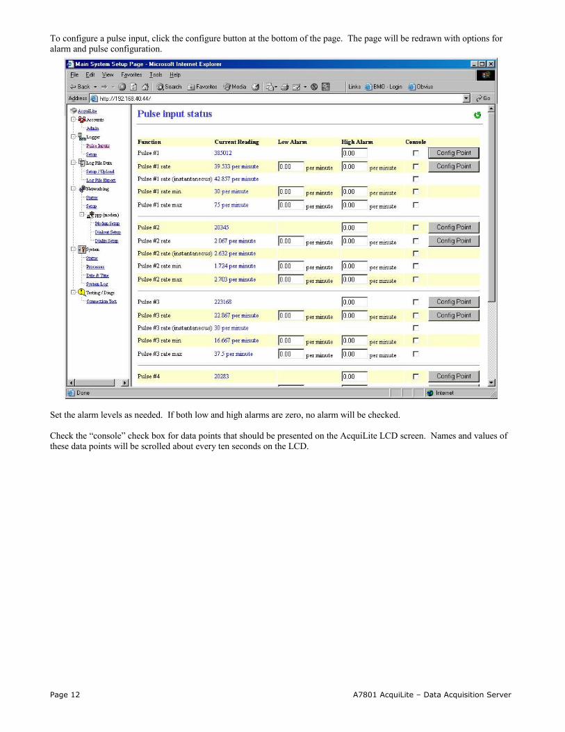
To configure a pulse input, click the configure button at the bottom of the page. The page will be redrawn with options for alarm and pulse configuration.
Set the alarm levels as needed. If both low and high alarms are zero, no alarm will be checked.
Check the “console” check box for data points that should be presented on the AcquiLite LCD screen. Names and values of these data points will be scrolled about every ten seconds on the LCD.
Page 12 A7801 AcquiLite – Data Acquisition Server
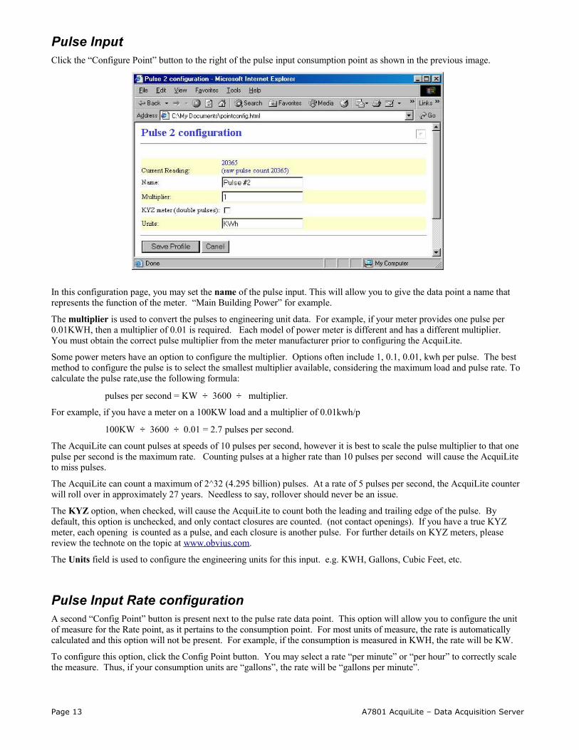
Pulse Input Click the “Configure Point” button to the right of the pulse input consumption point as shown in the previous image.
In this configuration page, you may set the name of the pulse input. This will allow you to give the data point a name that represents the function of the meter. “Main Building Power” for example.
The multiplier is used to convert the pulses to engineering unit data. For example, if your meter provides one pulse per 0.01KWH, then a multiplier of 0.01 is required. Each model of power meter is different and has a different multiplier. You must obtain the correct pulse multiplier from the meter manufacturer prior to configuring the AcquiLite.
Some power meters have an option to configure the multiplier. Options often include 1, 0.1, 0.01, kwh per pulse. The best method to configure the pulse is to select the smallest multiplier available, considering the maximum load and pulse rate. To calculate the pulse rate,use the following formula:
pulses per second = KW ÷ 3600 ÷ multiplier.
For example, if you have a meter on a 100KW load and a multiplier of 0.01kwh/p
100KW ÷ 3600 ÷ 0.01 = 2.7 pulses per second.
The AcquiLite can count pulses at speeds of 10 pulses per second, however it is best to scale the pulse multiplier to that one pulse per second is the maximum rate. Counting pulses at a higher rate than 10 pulses per second will cause the AcquiLite to miss pulses.
The AcquiLite can count a maximum of 2^32 (4.295 billion) pulses. At a rate of 5 pulses per second, the AcquiLite counter will roll over in approximately 27 years. Needless to say, rollover should never be an issue.
The KYZ option, when checked, will cause the AcquiLite to count both the leading and trailing edge of the pulse. By default, this option is unchecked, and only contact closures are counted. (not contact openings). If you have a true KYZ meter, each opening is counted as a pulse, and each closure is another pulse. For further details on KYZ meters, please review the technote on the topic at www.obvius.com.
The Units field is used to configure the engineering units for this input. e.g. KWH, Gallons, Cubic Feet, etc.
Pulse Input Rate configurationA second “Config Point” button is present next to the pulse rate data point. This option will allow you to configure the unit of measure for the Rate point, as it pertains to the consumption point. For most units of measure, the rate is automatically calculated and this option will not be present. For example, if the consumption is measured in KWH, the rate will be KW.
To configure this option, click the Config Point button. You may select a rate “per minute” or “per hour” to correctly scale the measure. Thus, if your consumption units are “gallons”, the rate will be “gallons per minute”.
Page 13 A7801 AcquiLite – Data Acquisition Server

Pulse Grouping The AcquiLite has the ability to track related pulse inputs from KWH and KVARH meters. To enable this, check the group option in the Logger/setup page. The following change will be shown in the Pulse Input – status page.
Notice that there are now four new data points after pulse inputs one and two. The AcquiLite will calculate the following based on the two points in the group.
Apparent Power (demand): The apparent power is calculated at the end of the logging interval, that shows the average KVA during that period.
Apparent Power (instantaneous): The instantaneous apparent power is calculated the same way as the demand value, however the instantaneous rate points are used in the calculation. This point is updated every time a new pulse arrives at the AcuqiLite inputs. This point may be invalid if no pulses were counted on either input during the log interval.
Power Factor (demand): The power factor is calculated at the end of the logging interval, that shows the average during that period.
Power Factor (instantaneous): The instantaneous power factor is calculated the same way as the demand value, however the instantaneous rate points are used in the calculation. This point is updated every time a new pulse arrives at the AcuqiLite inputs. This point may be invalid if no pulses were counted on either input during the log interval.
Note: when configuring the pulse inputs in a group, the KWH pulse input must be attached to input one or three, and the KVARH pulse input must be attached to input two or four.
Logger SetupSerial Number: This is the Unique serial number of the AcquiLite. It is also used as the Ethrenet MAC address. The Serial Number is used in all log file descriptors when uploaded to a central database website such as BMO.
Page 14 A7801 AcquiLite – Data Acquisition Server

System Name: This is the name of the AcquiLite. This name will be present on all log file descriptors when uploaded to a central database website such as BMO. It is helpful to name the AcquiLite based on the physical location of the system, or building.
Log Interval: This option sets the log interval for the AcquiLite. Options range from once per minute to once per hour. All of the selections are evenly divisible by one hour. The AcquiLite calculates the next log time by finding the next multiple of the log period past the start of the hour. For example, if the log period is 15 minutes, log readings will be taken at 0, 15, 30 and 45 minutes past the hour. The log period is not calculated based on “15 minutes after the last reading”
When the AcquiLite is first started, it will take an initial reading immediately. Following that, the next log reading will be calculated as a multiple of the log period after the hour. The initial reading is taken to allow the AcquiLite to gather information for meters that require demand calculations, as well as provide accurate information starting when the AcquiLite is booted.
Instantaneous calculation history: By default, the AcquiLite calculates the instantaneous rate of consumption based on how long it took for the last 5 pulses to be counted. You can change this to calculate based on the last 2 to 20 pulses. Setting this to a smaller number causes the instantaneous rate to jump around in value more than a larger number.
Group KWh/KVARh inputs 1 and 2, (and 3+4): point 1=kwh, point2=kvarh, calculate kva, and power factor for the 'group'. For further details, see the previous section on point groups.
Demo Mode: When checked, the AcquiLite will generate pulses internally, and blink the pulse input LEDs. This is useful for demonstrating the AcquiLite to a customer, or creating log data to review the log file formats. This option should not be enabled in devices that are deployed as working units.
Networking
Network StatusThis page displays the current status of the AcquiLite network connections. The basic network address and netmask will be shown for both the ethernet connection and PPP connection. If the AcquiLite has not made a PPP connection, the PPP address and gateway will be zero. Otherwise it will show the value of the current or last connection.
Gateway address: 192.168.40.1DNS: 70.99.203.62Interface table:# IP addr. Mask Up Type MTU Flags Peer/router- --------------- --------------- --- ----- ---- ------ ---------------0 192.168.40.44 255.255.255.0 yes eth 600 * 192.168.40.1 6 0.0.0.0 255.255.255.255 no ppp 600 0.0.0.0
Ethernet setupThe ethernet setup page has the following options:
IP Address: The ip address of the ethernet interface: Default 192.168.40.50
Netmask: The netmask of the ethernet network. Default 255.255.255.0
Gateway Address: The gateway is the routing device that moves traffic from the LAN to the internet. The default is 192.168.40.1. If you do not have an internet connection for your lan, or you are using a crossover ethernet cable, leave this field blank.
DNS: This is the DNS server address. If you are using a dialout connection, these will be overridden by the address provided by your dialup isp. If you only use the AcquiLite on a crossover cable and/or dialin mode, you should leave these blank.
HTTP Proxy. If your LAN is connected to the internet using a sophisticated firewall, you may need to use the HTTP proxy feature. Check with your LAN administrator first, however if you don't have a proxy set on your computer (MSIE/Tools/Connections-tab/LAN-Settings) then you most likely don't need to configure the AcquiLite to use a proxy. If in doubt, leave this blank first, and try the connection test. If it fails, ask your LAN administrator about proxy servers, if any.
Page 15 A7801 AcquiLite – Data Acquisition Server

After changing any of the settings on this page, you will be required to reboot the AcquiLite Use the system/status web configuration page, or the LCD console to reboot the AcquiLite.
Troubleshooting Ethernet ProblemsAfter reconfiguring the ethernet settings you experience problems accessing the AcquiLite with your web browser, check the following items.
Verify that you rebooted the AcquiLite after making the changes to the network settings.
Use the AcquiLite LCD console. Check the IP address and Netmask. Verify these are correct.
Verify the network connection in your computer has the proper IP address, on the same subnet, to access the AcquiLite.
Modem SetupThis configuration option will allow you to configure specific features in the modem if needed. For most applications, the default settings are ok. The options are as follows:Modem type: multitech: A MultiTech modem was detected. (default on all A7801 AcquiLite devices)Modem Speed: Select the maximum baud rate to use. On noisy phone lines, try setting this to 14.4kbps for a more reliable connection.Modem setup string: This option allows the use of specialized modem setup strings. The default “AT” is sufficient for most applications. Click the “use default” button to enter the default setup string. Speaker Volume: This option sets whether the speaker is on or off.
Modem PPP DialoutThe AcquiLite has a dialout feature that will allow the AcquiLite to place an outboud call and upload data to a central database server. If the dialout feature is enabled, the dialout connection will be initiated before the data upload process is started. Dialout connections allow the AcquiLite to connect to a generic PPP server such as a RAS system, or an internet service provider (ATT Worldnet, Earthlink, Netcom, etc.) Internet services that require custom software such as AOL, Juno, and ATT Global are not supported. To test if a dialup service is supported, simply use the MS Windows built in dialup-networking feature and attempt to establish a connection. If successful, the AcquiLite should work with the service. You may wish to test the dialup account phone number, username and password with windows first to verify that the account works correctly.
Enable/Disable: turn on or off the ability to place an outbound call to an ISP. Note, when enabling this feature, the default gateway in the network setup webpage is removed. You must reboot after enabling or disabling dialout support to make the change take effect.Phone number to dial: This is the phone number to call. A comma can be used to pause for 1 second, useful after dialing 9 for an outside line. Username: the login or username of the dialup account at your ISP.Password: The passowrd for the ISP account.
Example Dialout to an ISP or RASThe AcquiLite has the ability to place phone calls to a Remote Access Server (RAS) or ISP in order to upload data that has been collected from the pulse output devices. This feature is useful when using the AcquiLite on a phone line with the Building Manager Online service, or with your own data collection server. Dialout configuration is not useful if you do not have a central database server to send the data to.
Step 1: Collect the necessary information. You will need some details about the ISP or RAS you will be calling.
Dialout server detailsDialout prefix and long distance access code (if needed) ie dial 9 for an outside line ______ISP or RAS telephone number: ________________________ ISP or RAS DNS server: ___.___.___.___ (optional)ISP or RAS login name _________________ISP or RAS password _________________
Dialout worksheet
Page 16 A7801 AcquiLite – Data Acquisition Server

Step 2: Plug a regular telephone into the phone line that the AcquiLite is to use. Verify the line has dialtone. Attempt dialing the ISP or RAS phone number, and confirm a modem answers the phone. If so, hangup, attach the AcquiLite to the phone line and proceed to the next step.
Step 3: Select the Network/PPP0/ModemSetup option from the AcquiLite configuration webpage. Set the "setup string" by clicking on the "use default" button. The default is simply “AT”. Set the "limit carrier speed" option to 33600. If the phone line is noisy, and dialout connections are failing, you may want to reduce this setting. Click apply changes to save the setting.
Step 4: Select the Network/PPP0/DialoutSetup option from the AcquiLite configuration webpage. Verify the basic configuration page is shown (the default). If the “show basic” button is present in the lower right, click it to reduce the number of choices to the following.
A. Check the box to enable dialout.B. Enter the phone number in the space provided.C. Enter the login name and password to the isp dialup account in the space provided. D. Click Apply Changes to save the settings.
Step 5: Select the Network/Setup option from the AcquiLite configuration webpage. Set the DNS server(s) to the addresses provided by your dialup ISP account provider. Click the "Apply" button to save your changes. You will be prompted to reboot the AcquiLite for the changes to take effect. The DNS server address is required for dialup connections to be able to locate the buildingmanageronline.com website for data uploading. Reboot the AcquiLite (using the system/status page, or the console pushbutton menu.)
Step 6: Use the Connection Test page in the Testing/Diags menu on the AcquiLite for a full report of the dialout connection progress. Even if you are not using the BMO service, you can still test dialout with this feature. You may however receive an error that the AcquiLite is not allowed to transfer data to the BMO server. Further information on the connection test is provided in the connection test section of this manual.
Modem PPP DialinThe AcquiLite is designed to allow incomming connections from any generic PPP system including MacOS, Linux, Windows 9x, XP and 2000. The dialin feature is disabled by default, and must be enabled from LCD console or the dialin options menu in order to receive calls. Dialin options include the following.
Enabled: Check this checkbox to enable dialin support. When checked, the AcquiLite will answer any ring on the phone line, after the first ring. If not checked, the AcquiLite will never answer a ring on the phone line.
Local IP address: This is the IP address assigned to the AcquiLite side of the dialin connection. This address is the one which you must use on the computer in the web browser address line when remotely accessing the AcquiLite with a dialin connection. The default is 192.168.238.1
Remote IP address: This is the IP address assigned to the calling computer. The default is 192.168.238.2
Netmask: The netmask that defines the subnet for both the local and remote ip addresses. The default is 255.255.255.0
Unless you have specific requirements, the default IP, remote IP and Netmask should be sufficient.
Example Dialin from a Win98/ME computerThe AcquiLite has the ability to receive and answer phone calls from a Windows computer in order to allow remote configuration, or to collect data that has been logged from the pulse output devices. This feature is useful when using the AcquiLite on a phone line and a central database server is not present. The dialin feature will support the Windows builtin dialup networking features, and can be used as easily as a dialup ISP service.
Step 1: Collect the necessary information. You will need some details about the ISP or RAS you will be calling.
Dialin detailsA dedicate phone line is required, and can not be shared with a fax machine or other device. Telephone number: ________________________ (the phone line the AcquiLite is attached to)Static IP address: 192.168.238.1 (the AcquiLite PPP IP address)Static Netmask: 255.255.255.0 Remote Address: 192.168.238.2 (the IP address assigned to the calling computer)Admin password: ________________________
Dialin Address Worksheet..
Page 17 A7801 AcquiLite – Data Acquisition Server

Step 2: Plug a regular telephone into the phone line that the AcquiLite is to use. Verify the line has dialtone. Use a second telephone and dial the AcquiLite phone number and verify the first telephone rings, and can be answered. If it does not ring, verify the telephone number dialed is actually associated with physical phone line. If the line tests ok, hangup, attach the AcquiLite to the phone line and proceed to the next step.
Step 3: Select the Network/PPP0/ModemSetup option from the AcquiLite configuration webpage. set the "setup string" by clicking on the "use default" button. Click apply changes to save the setting.
Step 4: Select the Network/PPP0/DialinSetup option from the AcquiLite configuration webpage.
A. Check the "dialin enabled" option B. Set the IP, Netmask, and Remote Address as shown in Figure 9 - Dialin Address Worksheet. The IP addresses
shown (factory default) will work for most dialup connections. If you make changes to the IP address, make note of it for future use.
C. Click "Apply" to save your changes.
Step 5: Dialing into the AcquiLite with Windows:
A. From a Windows 95/98/ME computer, select the Start Menu, and then select the Control Panel. Double click the "dialup networking" folder.
B. Click "Make a new connection" C. Name the connection with an appropriate name for the AcquiLite. Click Next. D. Enter the phone number used to call the AcquiLite as shown in the Dialin Address Worksheet. Click Next, then
Finish. E. Double click the new connection icon in the dialup networking folder. F. Verify the phone number is accurate G. Enter “admin” as the login name, When prompted, enter the password to the AcquiLite admin account. (default is
“admin”H. Click Properties to show a configuration dialog for the connection. I. Click the Network tab, verify the dialup server type is "PPP" and the TCP/IP protocol is the only item checked in
the "allowed protocols area" J. Click TCP/IP Properties, and verify the connection uses a server assigned IP address. K. Click OK to close this dialog. L. Click the "Connect" button to dialin to the AcquiLite.
Once the connection is established, use your web browser to connect to the AcquiLite by entering
http://192.168.238.1/setup/Where 192.168.238.1 is the Static IP address listed in the Dialin Address Worksheet.
Your browser will now be able to access the AcquiLite the same way as you did in the LAN/Direct Connection setup in previous sections of this manual.
Example Dialin from a WinXP computerThe AcquiLite is designed to allow connections from any generic PPP system including MacOS, Linux, Windows 9x, XP and 2000.
We have found that windows XP/2000 has a timeout issue that affects some computers but not others. When calling the AcquiLite with windows XP/2000 you may receive an error message stating that a loopback error was detected, preceded by windows hanging up promptly after connecting to the AcquiLite. If that is the case, a slight delay in the dial process for windows will correct the problem. Adding this delay in a dial script is detailed in steps #1 and #3 below. It is recommended that you test the dialout configuration first without the delay script first, and add it only if required.
Step 1: (optional) Using notepad, create a text file called “c:\windows\system32\ras\AcquiLite.scp”. In that text file, add the following script
proc main delay 2endproc
Save and close the file
Step 2: Create a windows networking connection.
A. From the control panel, select Network Connections. Click “Create a new connection”B. The “Connection Wizard” will appear with a welcome screen and no options. Click next.
Page 18 A7801 AcquiLite – Data Acquisition Server
C. Select “Connect to the internet” and click nextD. Select “Set up my connection manually” and click nextE. Select “Connect using a dialup modem” and click nextF. Enter “My AcquiLite” for the ISP name. (you may want to name each AcquiLite connection by the name of the
building where it resides. ) Click next.G. Enter the phone number of the phone line attached to the AcquiLite. Click next. H. Enter “admin” for the username, and the admin password in the password field. Uncheck the option “Make this the
default internet connection.” Click next. I. The connection wizard will show you that the setup is complete. Click Finish.
Step 3: (optional) Configure connection details.
A. Right click on the “My AcquiLite” connection icon you created in step 2 above. (you may also click the properties button in the dialout dialog box.
B. General Tab: defaults are ok. C. Options Tab: Verify the option “include windows login domain” is not checked. Set any timeout values if desired.D. Security Tab: Security: Use “Typical”, allow unsecured password. At the bottom of the dialog box, in the section
“Interactive Login and Scripting”. Check the “Run Script” checkbox. Click the browse button below the script name. Select the AcquiLite.scp file created in step one above. Click the open button. The script name should appear to the right of the Run Script checkbox.
E. Networking Tab: defaults are ok.F. Advanced Tab: defaults are ok. G. Click Ok to save the changes.
Step 4: Dial the connection.A. Double click the “My AcquiLite” connection icon.B. Complete the password field if it is blank. The password is the Admin password of the AcquiLite. C. Click the dial button. The modem usually takes between 40 and 60 seconds to establish a connection.
Once the connection is established, use your web browser to connect to the AcquiLite by entering
http://192.168.238.1/setup/Where 192.168.238.1 is the Static IP address listed in Figure 9 - Dialin Address Worksheet.
Your browser will now be able to access the AcquiLite the same way as you did in the LAN/Direct Connection setup in previous sections of this manual.
System Options
StatusThe system status page shows the current memory and flash disk utilization values, system up-time, battery status, and current time.
ProcessesThe system process table is shown in both tree and tabular formats. The process list is useful when contacting Obvius technical support.
Date and TimeThe AcquiLite keeps time using UTC or Universal time. All log files are recorded in UTC time as well. Timestamps shown on the AcquiLite local configuration pages are converted to local time for the convenience of the installer. The date/time configuration page provides the following options.
Date/time in UTC and Local time. Use the dropdown menu to set the time manually if needed. (click apply when done)
Time Server: Specify the dns name or ip address of your time server. The default “time.obvius.com” can be used if the AcquiLite has a connection to the Internet. The AcquiLite will attempt to synchronize time with the time server every time an upload session. This will ensure that the clock is checked and adjusted at a minimum of once per day. Typically, the synchronization will align the clock to within +-1 second of the internet time source or atomic clock. You may need to
Page 19 A7801 AcquiLite – Data Acquisition Server
verify if your firewall will allow NTP packets to pass through. Generally, it is better to use a local time server if possible. The time server time.obvius.com supports both NTP and Rdate time protocols.
Note: the AcquiLite only supports the NTP time protocol.
Universal Time Is Your FriendLog data is stored in UTC time. This allows data collection services such as BMO to collect data from multiple sites in different time zones. If you are operating your own database system to store log data from the AcquiLite, it is best to store the data in UTC time in the database as well, and only convert it to local time when generating the final report or graph for the user.
If you store data in Local time, you will have the following issues.
1) Local time is relative. Is Local the time where the AcquiLite exists, or Local to where the data is stored. If local to the AcquiLite, you must shift each AcquiLite data set depending on its location.
2) There are about 11 time zones in the US. Some observe DST, others do not. These include Alaska, Aleutian, Arizona, Central, Eastern, Hawaii, Indiana, Michigan, Mountain, Pacific, and Samoa.
3) When converting to local time, there will be one hour of overlapping data in the fall when the time is adjusted for Daylight Savings time. ie, log entries run 12:45, 1:00, 1:15, 1:30, 1:45, 1:00, 1:15, 1:30, 1:45, 2:00am. This will prevent you from sorting your data by time in your database.
4) In the spring, you will have a gap in the data from 1:59 to 3:00am. This can cause problems if you are calculating demand values based on consumption.
5) Converting Local time to any other timezone usually involves converting it to UTC first.
Using UTC time solves these problems elegantly. The best practice is to store data in the database in UTC format and then convert the information when generating a report for the user.
For example, if you wish to draw a graph of KW over Time, prompt the user for a date range, say Jan 1 midnight to Jan 2 midnight. Take the user specified end points and convert these times from Local time to UTC. Next, create an SQL query using the new UTC formatted data as your select statement. ie:
SELECT * from TABLE where time > '2003-01-01 08:00:00' and time < '2003-01-02 08:00:00'
Note the time is 8 hours ahead of local time. This example is for Pacific which is 8 hours off from UTC. This will return a list of data points between the two specified time ranges. Next, plot the data on a graph, using the UTC times for start and end points. Lastly, when drawing the 'time' legend on the graph, convert the values back to Local time before displaying. Ie, 2003-01-01 00:00:00 to 2003-01-02 00:00:00. Any division lines on the time axis can be handled the same way. The advantage of using this technique is that it will properly draw a graph across DST change boundaries. The graph axis is based on UTC time with no DST, and will not show a gap or overlap a the time of the change. The axis labeling will be correct as well, matching the UTC times precisely.
Another way to handle the conversion is to query and convert all the returned timestamps to local time before drawing the graph. This is useful if you do not have detailed control over the graph legend drawing process. This technique will not properly graph across DST changes as the graph is based on local time including DST changes.
System logsThe AcquiLite can keep several log files that report the general operation of the system, not related to the normal data logs. These include the following:
System Messages: A list of system log messages related to the operation of the AcquiLite. These include the upload log messages, dialin/out, time changes, and any system errors that have ocurred.
Logger Configuration File: This page allows you to view, in text format, the configuration options of the system.
Pulse input configuration file: This page allows you to view, in text format, the configuration options of the pulse inputs.
Pulse log data (html): This page will allow you to view, in a web page, all the stored pulse log data on the AcquiLite.
Pulse log data mb-001.log (export) This page will provide the pulse log data in text (csv) format. You may need to right-click on the mb-001.log link and select “save target as” from the menu to save the log data to your computer hard disk.
Purge Log Files: This button will clear all the system log files listed on this page, but not the meter data log files. (deletes kernel, boot, ftp, messages, upload log files)
Page 20 A7801 AcquiLite – Data Acquisition Server

Diagnostics
Connection TestThe connection test page will attempt to establish an HTTP session with the specified upload server. Click the “begin test” to start this process. Information will be printed in black. Success responses will be printed in Green, failure messages will be printed in Red. A sample upload test follows:
Note: Use the System/SystemLog page to set the log report level to Debug for more detailed information.'2004-03-13 00:03:59',upload,INFO,ProcessUpload: Starting session: v0.04.0312b'2004-03-13 00:03:59',upload,INFO,ProcessUpload: Logfile upload attempt 1 (max 3) started.'2004-03-13 00:03:59',upload,INFO,ProcessUpload: HTTP session trace enabled.'2004-03-13 00:03:59',upload,INFO,ProcessUpload: PPP Dialout disabled, connecting by Ethernet LAN.'2004-03-13 00:03:59',upload,INFO,GetConnectionDetails: Upload URL looks ok,
resolving address for www.buildingmanageronline.com'2004-03-13 00:04:02',upload,INFO,SendAcquiLiteStatus: sending info to remote server.'2004-03-13 00:04:02',upload,INFO,TCPConnect: connecting to server at 70.99.203.62:80'2004-03-13 00:04:03',upload,INFO,ReadUploadResult: Finished reading data from remote host.'2004-03-13 00:04:03',upload,INFO,ReadUploadResult: Got: SUCCESS'2004-03-13 00:04:03',upload,INFO,SendAcquiLiteStatus: AcquiLite status information was uploaded.'2004-03-13 00:04:03',upload,INFO,UploadAllLogFiles: creating log file to upload'2004-03-13 00:04:03',upload,INFO,UploadAllLogFiles: Start upload 3 records'2004-03-13 00:04:03',upload,INFO,TCPConnect: connecting to server at 70.99.203.62:80'2004-03-13 00:04:03',upload,INFO,SendDataFile: original log filesize = 291, total bodysize = 1479'2004-03-13 00:04:04',upload,INFO,ReadUploadResult: Finished reading data from remote host. '2004-03-13 00:04:04',upload,INFO,ReadUploadResult: Got: SUCCESS'2004-03-13 00:04:04',upload,INFO,UploadAllLogFiles: 3 Log data records were uploaded successfully'2004-03-13 00:04:04',upload,INFO,UploadAllLogFiles: Finished file upload procedure.'2004-03-13 00:04:04',upload,INFO,SyncAllConfigFiles: Starting config file sync with remote server.'2004-03-13 00:04:04',upload,INFO,TCPConnect: connecting to server at 70.99.203.62:80'2004-03-13 00:04:05',upload,INFO,GetConfigManifest: finished sending manifest request, reading result.'2004-03-13 00:04:05',upload,INFO,GetConfigManifest: config file loggerconfig.ini checksum match. '2004-03-13 00:04:06',upload,INFO,GetConfigManifest: config file mb-001.ini differs'2004-03-13 00:04:06',upload,INFO,GetConfigManifest: local file is newer by 31418 seconds.'2004-03-13 00:04:06',upload,INFO,SyncAllConfigFiles: Remote configuration files are allowed.'2004-03-13 00:04:06',upload,INFO,GetConfigManifest: config file manifest download complete'2004-03-13 00:04:06',upload,INFO,TCPConnect: connecting to server at 70.99.203.62:80'2004-03-13 00:04:07',upload,INFO,SendConfigFile: Start upload mb-001.ini'2004-03-13 00:04:08',upload,INFO,ReadUploadResult: Finished reading data from remote host. '2004-03-13 00:04:08',upload,INFO,ReadUploadResult: Got: SUCCESS'2004-03-13 00:04:08',upload,INFO,SendConfigFile: config file uploaded successfully'2004-03-13 00:04:08',upload,INFO,SyncTime: adjusted clock drift 0 seconds'2004-03-13 00:04:08',upload,INFO,ProcessUpload: Upload process completed in 9 seconds'2004-03-13 00:04:08',upload,INFO,ProcessUpload: Upload results: 2 ok, 0 fail'2004-03-13 00:04:08',upload,INFO,ProcessUpload: Next upload scheduled for Mar 13, 2004 0:12:08 UTC.
Note in the last section where SUCCESS is indicated. (highlighted in this example for clarity).
LCD ConsoleThe AcquiLite has an LCD console and two push buttons labeled “menu” and “select”. These can be used to configure some of the basic features of the AcquiLite. The intended purpose of the console is to configure the AcquiLite to a point where a computer can communicate with it for further detailed configuration.
When the AcquiLite is running, it will show “AcquiLite Ready” and the current time alternated with the ethernet IP address. If you choose to enable the console display of data points, the LCD will also show the selected point names and current reading values. The display will change to the next listed item about once every 10 seconds. If a data point name is longer than will fit on the 16 character wide display, it will be scrolled. Pressing the select button will cause the display to change to the next configured item. Pressing the select button quickly will skip through multiple display points.
Pressing the Menu button will cause the main menu to appear. Once [Main Menu] is shown on the console, the menu button will change the menu option, and the select button will take action on the currently displayed option. Some options provide sub menus, others allow you to edit the option value. The following is a tree display of the main menu and sub menus.
[Main Menu]TCP/IP Config
[TCP/IP Config]IP AddressNetmask
Page 21 A7801 AcquiLite – Data Acquisition Server

GatewayDNS Server (previous menu)
Dialout[Dialout]Dialout On/OffPhone NumberUsernamePassword(previous menu)
Dialin[Dialin]Dialin On/Off(previous menu)
Data Upload[Data Upload]Show Serial#Upload URLUpload PasswordRetriesUpload Now(previous menu)
System[System]System NameLog IntervalDemo ModeShow Firmware(previous menu)
Shutdown(previous menu)
The TCP/IP sub menu will allow you to configure the ethernet settings for the AcquiLite. To edit the IP settings, use the menu button to change options, and press the select button to edit the option. Once selected, you will see the curent value displayed and a blinking square cursor on the first character. Press the menu button to change the character or digit. Press the select button to use the digit and move the cursor to the right one space. If you press the select button multiple times, the cursor will move right a similar number of spaces, allowing you to skip over characters that may be correct based on the previous settings. When you are finished entering the IP address, select a blank space with the menu button, and press select. Any characters still remaining to the right of the cursor will be eliminated. (ie, if changing 128.193.100.200 to 10.0.0.1, the new ip address will be several digits shorter than the old one.
Dialin: This menu provides the ability to enable or disable dialin support. From the console, the installer can enable dialin support and allow a remote user the ability to call the AcquiLite and configure the options without requiring a computer on site. For more information on connecting to the AcquiLite review the “Modem/PPP Dialin” section of this manual.
Shutdown: This option will stop the data logging processes and secure the flash memory. When secured, the console will state that the power may be disconnected. It is important to shut down the AcquiLite cleanly prior to disconnecting the power from the device. It is important to select this option before removing the battery from the AcquiLite.
The AcquiLite has an advanced menu that can be used to perform system checks and clear all configuration options to the default settings. To access the advanced menu, wait until the LCD shows “AcquiLite Ready” and press both the Menu and Select buttons at the same time. Hold both down together for about 10 seconds. When the advanced menu is displayed, you may release the two buttons. The following is a tree display of the advanced menu.
[Advanced Menu]Reset Config Clear Log(previous menu)
The Reset Config option will remove all the user settings, data, and passwords that have been configured and will return the AcquiLite to the factory default settings. This is mainly useful when reconfiguring an AcquiLite that has been used previously on a different job or project.
Page 22 A7801 AcquiLite – Data Acquisition Server
Log File DataThe AcquiLite stores interval data in non-volatile memory. The system battery maintains this memory when the power is disconnected. When the memory is 100% full, the oldest data records are overwritten by new records. The system can store approximately 37 days of data when logging every 15 minutes.
Log File StatusThe AcquiLite can display a list of log files in the "log file data/status" web configuration page. A bar graph will show the amount of storage capacity that is used by the existing log data.
Log File Format
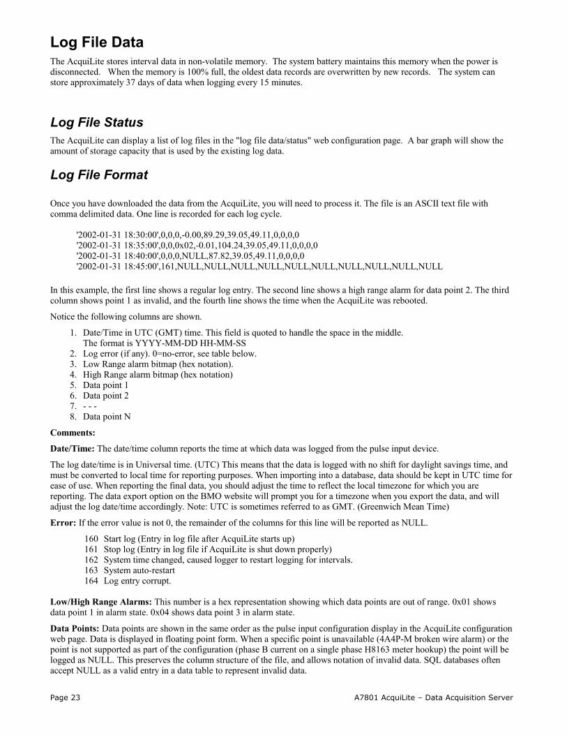
Once you have downloaded the data from the AcquiLite, you will need to process it. The file is an ASCII text file with comma delimited data. One line is recorded for each log cycle.
'2002-01-31 18:30:00',0,0,0,-0.00,89.29,39.05,49.11,0,0,0,0'2002-01-31 18:35:00',0,0,0x02,-0.01,104.24,39.05,49.11,0,0,0,0'2002-01-31 18:40:00',0,0,0,NULL,87.82,39.05,49.11,0,0,0,0'2002-01-31 18:45:00',161,NULL,NULL,NULL,NULL,NULL,NULL,NULL,NULL,NULL,NULL
In this example, the first line shows a regular log entry. The second line shows a high range alarm for data point 2. The third column shows point 1 as invalid, and the fourth line shows the time when the AcquiLite was rebooted.
Notice the following columns are shown.
1. Date/Time in UTC (GMT) time. This field is quoted to handle the space in the middle. The format is YYYY-MM-DD HH-MM-SS
2. Log error (if any). 0=no-error, see table below.3. Low Range alarm bitmap (hex notation). 4. High Range alarm bitmap (hex notation) 5. Data point 1 6. Data point 2 7. - - - 8. Data point N
Comments:
Date/Time: The date/time column reports the time at which data was logged from the pulse input device.
The log date/time is in Universal time. (UTC) This means that the data is logged with no shift for daylight savings time, and must be converted to local time for reporting purposes. When importing into a database, data should be kept in UTC time for ease of use. When reporting the final data, you should adjust the time to reflect the local timezone for which you are reporting. The data export option on the BMO website will prompt you for a timezone when you export the data, and will adjust the log date/time accordingly. Note: UTC is sometimes referred to as GMT. (Greenwich Mean Time)
Error: If the error value is not 0, the remainder of the columns for this line will be reported as NULL.
160 Start log (Entry in log file after AcquiLite starts up)161 Stop log (Entry in log file if AcquiLite is shut down properly)162 System time changed, caused logger to restart logging for intervals.163 System auto-restart164 Log entry corrupt.
Low/High Range Alarms: This number is a hex representation showing which data points are out of range. 0x01 shows data point 1 in alarm state. 0x04 shows data point 3 in alarm state.
Data Points: Data points are shown in the same order as the pulse input configuration display in the AcquiLite configuration web page. Data is displayed in floating point form. When a specific point is unavailable (4A4P-M broken wire alarm) or the point is not supported as part of the configuration (phase B current on a single phase H8163 meter hookup) the point will be logged as NULL. This preserves the column structure of the file, and allows notation of invalid data. SQL databases often accept NULL as a valid entry in a data table to represent invalid data.
Page 23 A7801 AcquiLite – Data Acquisition Server

For data exported from the BMO website, the columns that are invalid (NULL) are reported as blank fields. This makes it easier to import into MS Excel as blank cells. At some point in the future, the AcquiLite will be converted to report blank fileds rather than "NULL" to make direct import of data from the AcquiLite easier, as well as reduce the file size. Developers intending to use data files from the AcquiLite should handle both the word "NULL" as well as a blank column as indications of an invalid data point.
Log Storage CapacityThe AcquiLite stores approximately 3500 interval data records. At a 15 minute logging interval, this will allow about 37 days of data to be collected.
Uploading data to the BMO website.After the AcquiLite has been configured and has logged some data, you will want to collect the data for analysis. There are several ways of collecting the data from the AcquiLite including the Building Manager Online service. Other methods are noted in the data collection FAQ. This section details configuring the AcquiLite for use with the BMO service.
Step 1: First, use your browser to connect to the AcquiLite. Select the logger/setup page and in the “System Name” field enter a name for this AcquiLite to uniquely identify it on the BMO website. Because the BMO site can show multiple AcquiLite devices, it is important to have a descriptive name in this field.
Step 2: Select the Upload Data menu option. The following features are available:
AcquiLite Serial Number: This is the serial number that uniquely identifies this AcquiLite. This number can not be changed. When uploading data to the BMO website, this serial number is used to identify the AcquiLite to the BMO server.
Scheduled upload time: This option allows you to control when the AcquiLite will initiate the upload process. You can select any hour of the day, and the AcquiLite will select some time at random within that hour to start the upload. The random feature allows multiple AcquiLite devices to share a single dialup account or phone line by not starting the dialout at the same time for all devices. If the AcquiLite is on a LAN connection (DSL, Cable Modem, T1, etc) an upload time of "hourly" may be selected.
Upload data on alarm status change will cause the AcquiLite to initiate the upload process if any point on any pulse input data value enters or leaves an alarm state. This allows the AcquiLite to send data when an alarm is detected, and will upload that information to the BMO website in a timely manner. The BMO website will then send email notifications if necessary. If this option is disabled, the BMO website may not be able to send notifications until the end of the day when the AcquiLite calls in at its specified upload time.
Upload data on low disk alarm: This feature will cause the AcquiLite to attempt a data upload immediately if the log file storage area is more than 75% full.
Allow remote device configuration: If enabled, users may remotely configure alarms, multipliers, and other system features on the BMO website. When the AcquiLite uploads data to the BMO website, it will also download any new configuration information as needed. Note: if configuration changes are made to the AcquiLite, those changes will be uploaded to the BMO site. If configuration changes are made at both the AcquiLite and the BMO website, the most recent changes will be used.
Target Address to upload data: This is the website URL to upload data to. This should always be set to "http://www.buildingmanageronline.com/upload.php" unless you are configuring the AcquiLite to send data to your own internal database server. (see the Data Collection FAQ at obvius.com )
Password to upload data: This password is used by the BMO webserver to verify the AcquiLite device authentication before accepting the uploaded data. You should select a password other than the default, and make note of it for future reference.
Number of times to retry: In the event of a failure (often due to dialup problems, busy signals, etc) this option specifies the number of retries to attempt the upload again. If all retries fail, the AcquiLite will wait until the next scheduled upload time before trying again.
Time to wait before retry: In the event of a failure, the AcquiLite can be configured to wait for a specified period of time before attempting another connection. This option specifies how long to wait before retrying.
Step 3: Contact the Obvius Technical Support department. Please have the AcquiLite serial number and password to upload data handy. Your tech support representative will confirm your BMO account and will add the AcquiLite to one of your client databases.
Step 4: Click the "Upload Data Now" button. Your data should be sent to the BMO webserver.
Step 5: For more detailed information about the transfer process, use the Connection Test page in the Testing/Diags menu on the AcquiLite for a full report of the data upload progress.
Page 24 A7801 AcquiLite – Data Acquisition Server
Retrieving Data From the AcquiLiteOverview of how the system was designed to work.
Now that you have installed your AcquiLite and configured it to collect data from your meters and sensors, you will want to collect the data from your AcquiLite. This document will provide an overview for collecting data from the AcquiLite. Processing the data for billing reports, summaries, and other data processing are beyond the scope of this document.
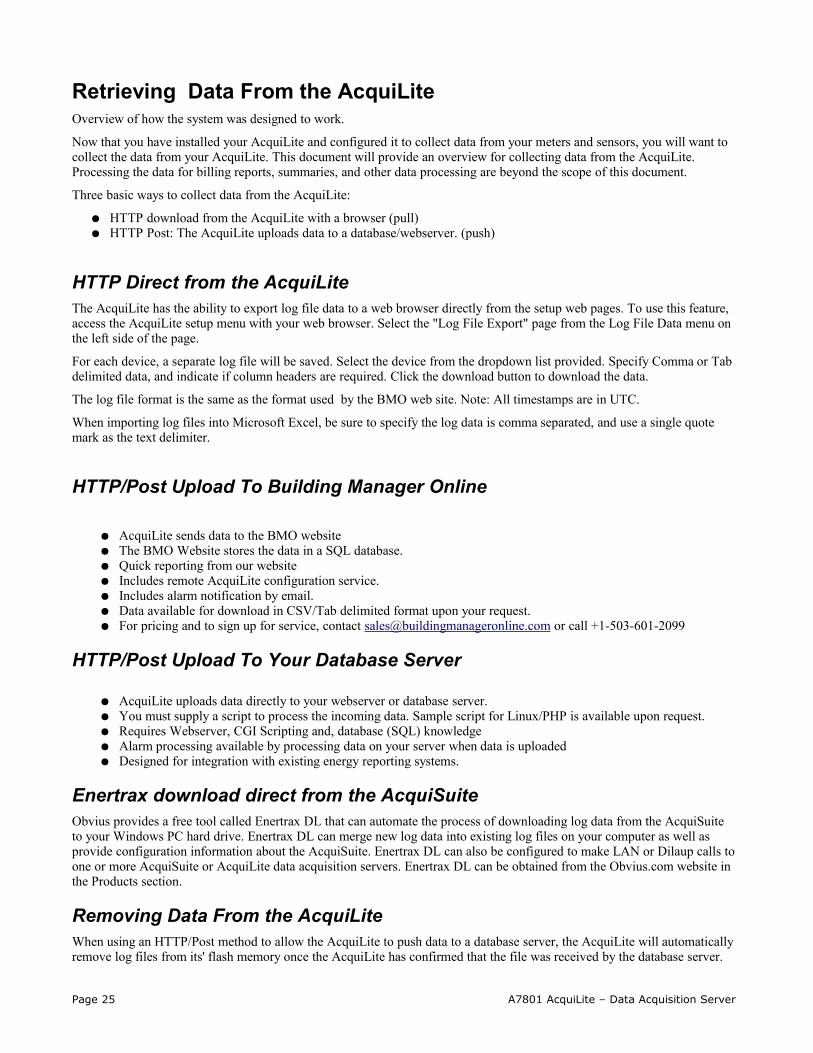
Three basic ways to collect data from the AcquiLite:
HTTP download from the AcquiLite with a browser (pull) HTTP Post: The AcquiLite uploads data to a database/webserver. (push)
HTTP Direct from the AcquiLiteThe AcquiLite has the ability to export log file data to a web browser directly from the setup web pages. To use this feature, access the AcquiLite setup menu with your web browser. Select the "Log File Export" page from the Log File Data menu on the left side of the page.
For each device, a separate log file will be saved. Select the device from the dropdown list provided. Specify Comma or Tab delimited data, and indicate if column headers are required. Click the download button to download the data.
The log file format is the same as the format used by the BMO web site. Note: All timestamps are in UTC.
When importing log files into Microsoft Excel, be sure to specify the log data is comma separated, and use a single quote mark as the text delimiter.
HTTP/Post Upload To Building Manager Online
AcquiLite sends data to the BMO website The BMO Website stores the data in a SQL database. Quick reporting from our website Includes remote AcquiLite configuration service. Includes alarm notification by email. Data available for download in CSV/Tab delimited format upon your request. For pricing and to sign up for service, contact [email protected] or call +1-503-601-2099
HTTP/Post Upload To Your Database Server
AcquiLite uploads data directly to your webserver or database server. You must supply a script to process the incoming data. Sample script for Linux/PHP is available upon request. Requires Webserver, CGI Scripting and, database (SQL) knowledge Alarm processing available by processing data on your server when data is uploaded Designed for integration with existing energy reporting systems.
Enertrax download direct from the AcquiSuiteObvius provides a free tool called Enertrax DL that can automate the process of downloading log data from the AcquiSuite to your Windows PC hard drive. Enertrax DL can merge new log data into existing log files on your computer as well as provide configuration information about the AcquiSuite. Enertrax DL can also be configured to make LAN or Dilaup calls to one or more AcquiSuite or AcquiLite data acquisition servers. Enertrax DL can be obtained from the Obvius.com website in the Products section.
Removing Data From the AcquiLiteWhen using an HTTP/Post method to allow the AcquiLite to push data to a database server, the AcquiLite will automatically remove log files from its' flash memory once the AcquiLite has confirmed that the file was received by the database server.
Page 25 A7801 AcquiLite – Data Acquisition Server
Enertrax DL also has an option to delete data from the AcquiLite
Linking to AcquiLite Device Status PagesIt may be helpful to create a shortcut or a hyperlink on another web page that will direct the browser to bring up a specific device status page in your browser. To do this, right click on the page and select properties. The url for the page will be shown on that dialog. Simply copy/paste this url into your link.
To format a URL that will bypass the username/password prompt, you can include the login information in the URL itself. Note however that this will allow any one to discover the password for the AcquiLite. Consider using the password in the url with caution.. This technique is shown in the following example:
http://mypassword:[email protected]/setup/loggersetup.cgi
Note: To allow the user to be prompted for the login/password, remove “mypassword:admin@” from the example URL.
More recent versions of web browsers may not allow passwords to be specified in the URL and may prompt the user to enter the password when accessing the device.
Firmware UpdateFrom time to time, Obvius may release firmware updates with additional features and system changes. To find out what firmware your AcquiLite has installed, view the system status page in your web browser, or select the “Show Firmware” option from the LCD console in the System menu. Firmware update files may be obtained from Obvius technical support.
The firmware update process requires an RS232 serial port and a windows computer to run the firmware update utility. Before starting this process, verify your computer has a serial port available. You may need to deactivate other software such as the palm pilot utility or ups monitor software. Some USB connected serial ports are not as fast or reliable as standard computer serial ports. We recommend using the Obvius A89-USB232 adapter product.
To update the firmware, use the following procedure.
Step 1: download your log data from the AcquiLite. Log data stored in the AcquiLite memory will not be preserved after the firmware update begins. In addition, you may wish to backup your AcquiLite configuration. Although most firmware updates will preserve the AcquiLite configuration, some updates may require changes to the config storage in the AcquiLite memory.
Step 2: Select the shutdown option from the AcquiLite LCD console. Note: do not simply power down the unit. Selecting the shutdown option causes the AcquiLite to make a backup copy of the pulse count and configuration in flash, so that it will be preserved while the firmware is being updated.
Step 3: Disconnect the power from the AcquiLite. Move the program jumper to the left two pins (closest to the programming connector), Attach a standard serial cable from the AcquiLite programming connector to your computer serial port. Use a DB9 male to DB9 female straight through cable, not a null-modem cable. After the AcquiLite is connected to the computer, reconnect the power to the AcquiLite. The power led on the AcquiLite will turn on, however the LCD will not show any message, nor will the Alive LED blink.
For USB to Ethernet adapters, use the system/device manager control panel to set the com port to a value of 1-4.
Step 4: Install the RFU update utility on your windows computer. The installation consists of simply unziping the RFUzip file to a directory on your C drive. Several files should be present in the same directory, including rfu.exe, flash.ini, coldload.bin, pilot.bin. Note: RFU v2.45 or later is required.
Step 5: Run the RFU.exe utility. Select the setup menu, and choose Communications. In the Communications Options, use the following settings.
Use Serial ConnectionBaud Rate: 57600 (Default) most computers can run at 115200 however.Comm port: Comm1 (use the comm port that you attached to the AcquiLite in step 3 above)Check “enable processor detection”Check “Use USB to Serial Converter”Click OK to save your options.
Page 26 A7801 AcquiLite – Data Acquisition Server

Step 6: Select the Setup menu, and choose “File locations”. The files are should be located in the RFU directory, however you may need to select them manually. The file locations to use are as follows:
Cold Loader: coldload.binPilot BIOS: pilot.binFlash Table: flash.ini.
To select each file location, click the “...” button to the right of the file name area, select the file from the RFU directory, and click ok. Click the OK button when finished with this dialog.
Step 7: From the File menu, select the “Load Flash Image” option.
Step 8: A dialog box with a file location item will be shown. Click the “...” button to the right and select the AcquiLite firmware image file. The firmware image file name will be “AL-1.09.0912.bin” or similar. Click OK when finished.
Step 9: A progress dialog will be shown. The RFU utility will download the image to the AcquiLite. If any problems are encountered, a dialog box will appear to alert you to the issue. When complete, the RFU utility will simply close the progress dialog.
Step 10: Disconnect the AcquiLite from the power connector. Remove the serial cable from the programming connector. Move the program jumper to the right two pins, (away from the programming connector).
Step 11: Reconnect the power to the AcquiLite. The AcquiLite should start up and continue operation. To verify the firmware, press the menu button until the “System” menu is shown, then press select. Next, press the Menu button until “show firmware” is displayed and press select. The new firmware version number will be shown on the LCD. Using a web browser, confirm your system configuration options; the AcquiLite should now be ready for service.
Page 27 A7801 AcquiLite – Data Acquisition Server


![#] +e A ) - 日本弁護士連合会│Japan Federation of … ý Â Â Ë Â Â Ä Â Â Â Å 1 ý Â Â Ë Â Â Ä Â Â Â Å 5U ÊKS 1 ý Â Â Ë Â Â Ä Â Â Â Å1 ý Â](https://img.pdfslide.net/doc/110x75/5ce9840888c993c0208d8cce/-e-a-japan-federation-of-y-a-a-e-a-a-ae.jpg)