Embed Size (px)
Citation preview
Acquisition of 3D Gaze Information from EyeballMovements using Inside-out Camera
Shoichi ShimizuAdvanced Technology R&D Center, Mitsubishi Electric Corporation8-1-1, Tsukaguchi-Honmachi, Amagasaki, Hyogo 661-8661, Japan
Hironobu FujiyoshiDept. of Computer Science, Chubu University1200 Matsumoto, Kasugai, Aichi 487-8501
ABSTRACTWe propose a method for obtaining 3D gaze information usinginside-out camera. Such information on 3D gaze points can be use-ful not only to clarify higher cognitive processes in humans butalso to reproduce the 3D shape of an object from eyeball move-ment simply by gazing at the object as an extension of the visualfunction. Using half-mirrors, an inside-out camera can capture aperson’s eyeball head-on and can capture the person’s visual fieldfrom a position equivalent to that of the eyeball. Here, the relation-ship between the gaze vector obtained from images of the eyeballand the gaze point in images capturing the visual field is expressedby a conversion equation. The 3D position of the gaze point canthen be estimated by using stereo constraints in two scene cameras.In an evaluation experiment, the gaze point could be estimated withan average error of about 15 pixels, and we also showed the 3D scanpath obtained by the proposed method from eyeball movement bygazing at the object.
Categories and Subject DescriptorsI.2.10 [Vision and Scene Understanding]: 3D/stereo scene anal-ysis
General TermsMEASUREMENT
Keywords3D gaze point, inside-out camera, stereo vision
1. INTRODUCTIONThe human eye enables a person to instantly absorb information
and act accordingly. As a consequence, information on a person’sgaze, which reveals what objects in the outside the world the personis looking at, can be valuable in determining that person’s behav-ioral intentions. Noton et al. discovered that similar scanpaths areused when a person is shown the same object at different times[1].Obtaining information on eye movement in this way can thereforebe expected to clarify higher cognitive processes in humans [2].
Permission to make digital or hard copies of all or part of this work forpersonal or classroom use is granted without fee provided that copies arenot made or distributed for profit or commercial advantage and that copiesbear this notice and the full citation on the first page. To copy otherwise, torepublish, to post on servers or to redistribute to lists, requires prior specificpermission and/or a fee./AH ’11/, Mar 13-13 2011, Tokyo, JapanCopyright 2011 ACM 978-1-4503-0426-9/11/03 ...$10.00.
Camera systems for detecting a person’s gaze have been com-mercially available for some time. These systems have been usedfor rehabilitation purposes in relation to impaired visual perceptionfunctions, for comparing and evaluating the visual perception ofroad signs, and for evaluating product usability [3, 4, 5, 6, 7]. Ad-ditionally, the Aided Eyes system proposed by Ishiguro et al. usesinformation on eye activity obtained by a sensor to augment hu-man memory [8]. These commercialized gaze measurement equip-ment consist of a camera for capturing the subject’s eyeball and ascene camera for capturing the subject’s visual field. Due to struc-tural considerations in camera installation, however, a scene cameracannot be placed at the same position as the eyeball, which meansthat the image obtained of the visual field is not the same as theactual visual field. Another problem is that the eyeball cannot becaptured head-on when attempting to measure gaze from eyeballimages since that would obstruct the subject’s visual field.In view of the above problems, we propose a method for ob-
taining 3D gaze information using inside-out camera. Using half-mirrors, an inside-out camera can capture a person’s eyeball head-on and can capture the person’s visual field from a position equiv-alent to that of the eyeball. Here, the relationship between the gazevector obtained from images of the eyeball and the gaze point inimages capturing the visual field is expressed by a conversion equa-tion. The 3D position of the gaze point can then be estimated byusing stereo constraints in two scene cameras. Such informationon 3D gaze points can be useful not only to clarify higher cogni-tive processes in humans but also to reproduce the 3D shape of anobject from eyeball movement simply by gazing at the object as anextension of the visual function.
2. EXISTINGGAZEMEASUREMENTEQUIP-MENT
In this section, we describe two types of existing gaze measure-ment equipment-head-mounted and standalone-and point out theadvantages and disadvantages of each.
2.1 Head-mounted typeThe head-mounted type of gaze measurement equipment [3, 4,
5] can capture both of the subject’s eyes and the subject’s visualfield, using two cameras for capturing the eyeballs and one camerafor capturing the visual field. This type of equipment can be usedto analyze the eye gaze of athletes, and it can be used in computergames by attaching a head-mounted display.
2.2 Standalone typeThe standalone type of gaze measurement equipment [6, 7] does
not make contact with the subject enabling eye gaze to be measuredin a natural state. It cannot, however, capture an image of the sub-
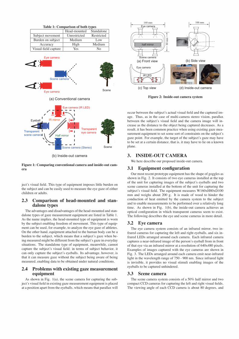
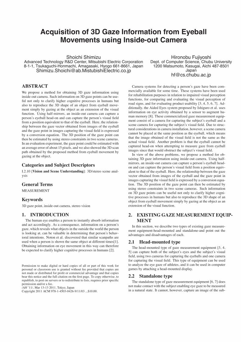
Table 1: Comparison of both typesHead-mounted Standalone
Subject movement Unrestricted RestrictedBurden on subject Medium Low
Accuracy High MediumVisual-field capture Yes No
Figure 1: Comparing conventional camera and inside-out cam-era
ject’s visual field. This type of equipment imposes little burden onthe subject and can be easily used to measure the eye gaze of eitherchildren or adults.
2.3 Comparison of head-mounted and stan-dalone types
The advantages and disadvantages of the head-mounted and stan-dalone types of gaze measurement equipment are listed in Table 1.As the name implies, the head-mounted type of equipment is wornby the subject enabling freedom of movement. This type of equip-ment can be used, for example, to analyze the eye gaze of athletes.On the other hand, equipment attached to the human body can be aburden to the subject, which means that a subject’s gaze when be-ing measured might be different from the subject’s gaze in everydaysituations. The standalone type of equipment, meanwhile, cannotcapture the subject’s visual field; in terms of subject behavior, itcan only capture the subject’s eyeballs. Its advantage, however, isthat it can measure gaze without the subject being aware of beingmeasured, enabling data to be obtained under natural conditions.
2.4 Problems with existing gaze measurementequipment
As shown in Fig. 1(a), the scene camera for capturing the sub-ject’s visual field in existing gaze measurement equipment is placedat a position apart from the eyeballs, which means that parallax will
Figure 2: Inside-out camera system
occur between the subject’s actual visual field and the captured im-age. Thus, as in the case of multi-camera stereo vision, parallaxbetween the subject’s visual field and the camera image will in-crease as the distance to the object being captured decreases. As aresult, it has been common practice when using existing gaze mea-surement equipment to set some sort of constraints on the subject’sgaze point. For example, the target of the subject’s gaze may haveto be set at a certain distance, that is, it may have to lie on a knownplane.
3. INSIDE-OUT CAMERAWe here describe our proposed inside-out camera.
3.1 Equipment configurationOur most recent prototype equipment has the shape of goggles as
shown in Fig. 2. It consists of two eye cameras installed at the topof the unit for capturing images of the subject’s eyeballs and twoscene cameras installed at the bottom of the unit for capturing thesubject’s visual field. The equipment measures W160xH80xD100mm and weighs about 200 g. It is made of wood to hinder theconduction of heat emitted by the camera system to the subjectand to enable measurements to be performed over a relatively longtime. As shown in Fig. 1(b), the inside-out camera achieves anoptical configuration in which transparent cameras seem to exist.The following describes the eye and scene cameras in more detail.
3.2 Eye cameraThe eye camera system consists of an infrared mirror, two in-
frared cameras for capturing the left and right eyeballs, and six in-frared LEDs arranged around each camera. Each infrared cameracaptures a near-infrared image of the person’s eyeball from in frontof that eye via an infrared mirror at a resolution of 640x480 pixels.Examples of images captured with the eye cameras are shown inFig. 3. The LEDs arranged around each camera emit near-infraredlight in the wavelength range of 750 - 900 nm. Since infrared lightis invisible, it provides no visual stimuli enabling images of theeyeballs to be captured unhindered.
3.3 Scene cameraThe scene camera system consists of a 50% half mirror and two
compact CCD cameras for capturing the left and right visual fields.The viewing angle of each CCD camera is about 80 degrees, and
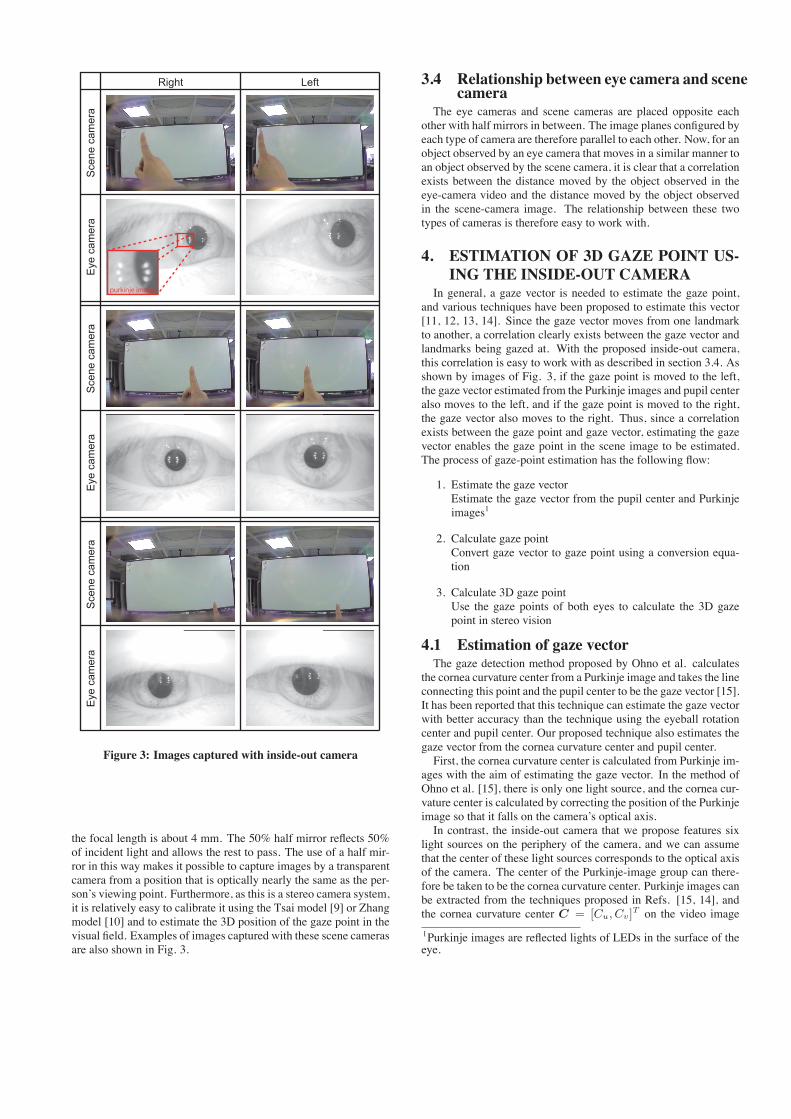
Figure 3: Images captured with inside-out camera
the focal length is about 4 mm. The 50% half mirror reflects 50%of incident light and allows the rest to pass. The use of a half mir-ror in this way makes it possible to capture images by a transparentcamera from a position that is optically nearly the same as the per-son’s viewing point. Furthermore, as this is a stereo camera system,it is relatively easy to calibrate it using the Tsai model [9] or Zhangmodel [10] and to estimate the 3D position of the gaze point in thevisual field. Examples of images captured with these scene camerasare also shown in Fig. 3.
3.4 Relationship between eye camera and scenecamera
The eye cameras and scene cameras are placed opposite eachother with half mirrors in between. The image planes configured byeach type of camera are therefore parallel to each other. Now, for anobject observed by an eye camera that moves in a similar manner toan object observed by the scene camera, it is clear that a correlationexists between the distance moved by the object observed in theeye-camera video and the distance moved by the object observedin the scene-camera image. The relationship between these twotypes of cameras is therefore easy to work with.
4. ESTIMATION OF 3D GAZE POINT US-ING THE INSIDE-OUT CAMERA
In general, a gaze vector is needed to estimate the gaze point,and various techniques have been proposed to estimate this vector[11, 12, 13, 14]. Since the gaze vector moves from one landmarkto another, a correlation clearly exists between the gaze vector andlandmarks being gazed at. With the proposed inside-out camera,this correlation is easy to work with as described in section 3.4. Asshown by images of Fig. 3, if the gaze point is moved to the left,the gaze vector estimated from the Purkinje images and pupil centeralso moves to the left, and if the gaze point is moved to the right,the gaze vector also moves to the right. Thus, since a correlationexists between the gaze point and gaze vector, estimating the gazevector enables the gaze point in the scene image to be estimated.The process of gaze-point estimation has the following flow:
1. Estimate the gaze vectorEstimate the gaze vector from the pupil center and Purkinjeimages1
2. Calculate gaze pointConvert gaze vector to gaze point using a conversion equa-tion
3. Calculate 3D gaze pointUse the gaze points of both eyes to calculate the 3D gazepoint in stereo vision
4.1 Estimation of gaze vectorThe gaze detection method proposed by Ohno et al. calculates
the cornea curvature center from a Purkinje image and takes the lineconnecting this point and the pupil center to be the gaze vector [15].It has been reported that this technique can estimate the gaze vectorwith better accuracy than the technique using the eyeball rotationcenter and pupil center. Our proposed technique also estimates thegaze vector from the cornea curvature center and pupil center.First, the cornea curvature center is calculated from Purkinje im-
ages with the aim of estimating the gaze vector. In the method ofOhno et al. [15], there is only one light source, and the cornea cur-vature center is calculated by correcting the position of the Purkinjeimage so that it falls on the camera’s optical axis.In contrast, the inside-out camera that we propose features six
light sources on the periphery of the camera, and we can assumethat the center of these light sources corresponds to the optical axisof the camera. The center of the Purkinje-image group can there-fore be taken to be the cornea curvature center. Purkinje images canbe extracted from the techniques proposed in Refs. [15, 14], andthe cornea curvature center C = [Cu, Cv]
T on the video image
1Purkinje images are reflected lights of LEDs in the surface of theeye.
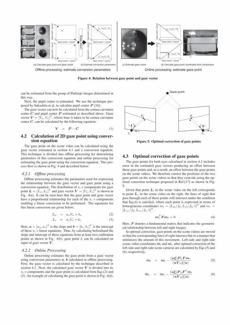
Figure 4: Relation between gaze point and gaze vector
can be estimated from the group of Purkinje images determined inthis way.Next, the pupil center is estimated. We use the technique pro-
posed by Sakashita et al. to calculate pupil center P [16].The gaze vector can now be calculated from the cornea curvature
center C and pupil center P estimated as described above. Gazevector V = [Vu, Vv]
T , whose base is taken to be cornea curvaturecenterC, can be calculated by the following equation:
V = P −C (1)
4.2 Calculation of 2D gaze point using conver-sion equation
The gaze point on the scene video can be calculated using thegaze vector estimated in section 4.1 and a conversion equation.This technique is divided into offline processing for determiningparameters of this conversion equation and online processing forestimating the gaze point using the conversion equation. This pro-cess flow is shown in Fig. 4 and described below.
4.2.1 Offline processingOffline processing estimates the parameters used for expressing
the relationship between the gaze vector and gaze point using aconversion equation. The distribution of u, v components for gazepoint L = [Lu, Lv]
T and gaze vector V = [Vu, Vv]T is shown in
Fig. 4(a). It can be seen here that the gaze point and gaze vectorhave a proportional relationship for each of the u, v componentsenabling a linear conversion to be performed. The equations forthis linear conversion are given below:
Lu = auVu + bu (2)
Lv = avVv + bv (3)
Here, a = [au, av]T is the slope and b = [bu, bv]
T is the interceptof these u, v linear equations. Thus, by calculating beforehand theslope and intercept of these equations from at least two calibrationpoints as shown in Fig. 4(b), gaze point L can be calculated oninput of gaze vector V .
4.2.2 Online ProcessingOnline processing estimates the gaze point from a gaze vector
using conversion parameters a, b calculated in offline processing.First, the gaze vector is calculated by the technique described insection 4.1. Next, the calculated gaze vector V is divided into itsu, v components and the gaze point is calculated from Eqs.(2) and(3). An example of calculating the gaze point is shown in Fig. 4(d).
Figure 5: Optimal correction of gaze points
4.3 Optimal correction of gaze pointsThe gaze points for both eyes calculated in section 4.2 includes
error in the estimated gaze vectors producing an offset betweenthese gaze points and, as a result, an offset between the gaze pointson the scene videos. We therefore correct the positions of the twogaze points on the scene videos so that they coincide using the op-timal correction technique proposed in Ref.[17] as shown in Fig.5.Given that point Ll in the scene video on the left corresponds
to point Lr in the scene video on the right, the lines of sight thatpass through each of these points will intersect under the conditionthat Eq.(4) is satisfied, where each point is expressed in terms ofhomogeneous coordinates ml = [Lul/f0, Lvl/f0, 1]
T and mr =[Lur/f0, Lvr/f0, 1]
T .
mTr Fml = 0 (4)
Here, F denotes a fundamental matrix that indicates the geometri-cal relationship between left and right images.In optimal correction, gaze points on the scene videos are moved
so that the corresponding lines of sight intersect but in a manner thatminimizes the amount of this movement. Left-side and right-sidescene-video coordinates m̂l and m̂r after optimal correction of theleft-side and right-side scene cameras are calculated by Eqs.(5) and(6), respectively.
m̂l = ml − (uξ)P kFmr
(uV 0[ξ]u)(5)
m̂r = mr − (uξ)P kFTml
(uV 0[ξ]u)(6)
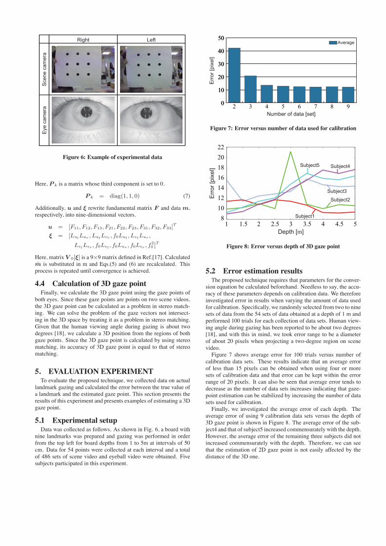
Figure 6: Example of experimental data
Here, P k is a matrix whose third component is set to 0.
P k = diag(1, 1, 0) (7)
Additionally, u and ξ rewrite fundamental matrix F and datam,respectively, into nine-dimensional vectors.
u = [F11, F12, F13, F21, F22, F23, F31, F32, F33]T
ξ = [LulLur , LulLvr , f0Lul , LvlLur ,
LvlLvr , f0Lvl , f0Lur , f0Lvr , f20 ]
T
Here, matrix V 0[ξ] is a 9×9 matrix defined in Ref.[17]. Calculatedm̂ is substituted in m and Eqs.(5) and (6) are recalculated. Thisprocess is repeated until convergence is achieved.
4.4 Calculation of 3D gaze pointFinally, we calculate the 3D gaze point using the gaze points of
both eyes. Since these gaze points are points on two scene videos,the 3D gaze point can be calculated as a problem in stereo match-ing. We can solve the problem of the gaze vectors not intersect-ing in the 3D space by treating it as a problem in stereo matching.Given that the human viewing angle during gazing is about twodegrees [18], we calculate a 3D position from the regions of bothgaze points. Since the 3D gaze point is calculated by using stereomatching, its accuracy of 3D gaze point is equal to that of stereomatching.
5. EVALUATION EXPERIMENTTo evaluate the proposed technique, we collected data on actual
landmark gazing and calculated the error between the true value ofa landmark and the estimated gaze point. This section presents theresults of this experiment and presents examples of estimating a 3Dgaze point.
5.1 Experimental setupData was collected as follows. As shown in Fig. 6, a board with
nine landmarks was prepared and gazing was performed in orderfrom the top left for board depths from 1 to 5m at intervals of 50cm. Data for 54 points were collected at each interval and a totalof 486 sets of scene video and eyeball video were obtained. Fivesubjects participated in this experiment.
0
10
20
30
40
50
987654320
10
20
30
40
50
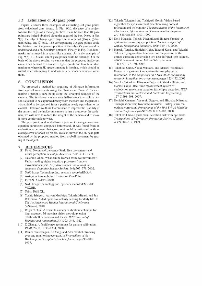
Figure 7: Error versus number of data used for calibration
Figure 8: Error versus depth of 3D gaze point
5.2 Error estimation resultsThe proposed technique requires that parameters for the conver-
sion equation be calculated beforehand. Needless to say, the accu-racy of these parameters depends on calibration data. We thereforeinvestigated error in results when varying the amount of data usedfor calibration. Specifically, we randomly selected from two to ninesets of data from the 54 sets of data obtained at a depth of 1 m andperformed 100 trials for each collection of data sets. Human view-ing angle during gazing has been reported to be about two degrees[18], and with this in mind, we took error range to be a diameterof about 20 pixels when projecting a two-degree region on scenevideo.Figure 7 shows average error for 100 trials versus number of
calibration data sets. These results indicate that an average errorof less than 15 pixels can be obtained when using four or moresets of calibration data and that error can be kept within the errorrange of 20 pixels. It can also be seen that average error tends todecrease as the number of data sets increases indicating that gaze-point estimation can be stabilized by increasing the number of datasets used for calibration.Finally, we investigated the average error of each depth. The
average error of using 9 calibration data sets versus the depth of3D gaze point is shown in Figure 8. The average error of the sub-ject4 and that of subject5 increased commensurately with the depth.However, the average error of the remaining three subjects did notincreased commensurately with the depth. Therefore, we can seethat the estimation of 2D gaze point is not easily affected by thedistance of the 3D one.
5.3 Estimation of 3D gaze pointFigure 9 shows three examples of estimating 3D gaze points
from calculated gaze points. In Fig. 9(a), the gaze of a subjectfollows the edges of a rectangular box. It can be seen that 3D gazepoints are indeed obtained along the edges of the box. Next, in Fig.9(b), the subject changes gaze target in the order of©1 sign,©2 hu-man being, and ©3 box. The corresponding 3D gaze points couldbe obtained, and the general position of the subject’s gaze could beunderstood and a 3D ScanPath obtained. Finally, in Fig. 9(c), land-marks are arranged in a spiral-like manner. As in the example ofFig. 9(b), a 3D ScanPath of gaze points could be obtained. On thebasis of the above results, we can say that the proposed inside-outcamera can be used to estimate 3D gaze points and to obtain infor-mation on where in 3D space someone is looking, which should beuseful when attempting to understand a person’s behavioral inten-tions.
6. CONCLUSIONWe proposed a method for acquiring of 3D gaze information
from eyeball movements using the “Inside-out Camera” for esti-mating a person’s gaze point using the structural features of thecamera. The inside-out camera uses half-mirrors to enable a per-son’s eyeball to be captured directly from the front and the person’svisual field to be captured from a position nearly equivalent to theeyeball. However, we think that we need to improve the usability ofthe system, and the inside-out camera is just a prototype. In partic-ular, we will have to reduce the weight of the camera and to makeit more comfortable to wear.The gaze point is calculated from a gaze vector using conversion-
equation parameters computed beforehand. It was found from anevaluation experiment that gaze point could be estimated with anaverage error of about 15 pixels. We also showed the 3D scan pathobtained by the proposed method from eyeball movement by gaz-ing at the object.
7. REFERENCES[1] David Noton and Lawrence Stark. Eye movements and
visual perception. Scientific American, 224:35–43, 1971.[2] Takehiko Ohno. What can be learned from eye movement? :
Understanding higher cognitive processes from eyemovement analysis. Cognitive studies : bulletin of theJapanese Cognitive Science Society, 9(4):565–579, 2002.
[3] NAC Image Technology Inc. eyemark recorderEMR-9.[4] Arrington Research, inc. EyetrackerViewPoint.[5] ISCAN. AA-ETL-500B.[6] NAC Image Technology Inc. eyemark recorderEMR-AT
VOXER.[7] Tobii. Tobii XL.[8] Yoshio Ishiguro, Adiyan Mujibiya, Takashi Miyaki, and Jun
Rekimoto. Aided eyes: Eye activity sensing for daily life. InThe 1st Augmented Human International Conference(AH2010), 2010.
[9] Roger Y. Tsai. A versatile camera calibration technique forhigh-accuracy 3d machine vision metrology usingoff-the-shelf tv cameras and lenses. IEEE Journal ofRobotics and Automation, 3(4):323–344, 1922.
[10] Z. Zhang. A flexible new technique for camera calibration.PAMI, 22(11):1330–1334, 2000.
[11] Rainer Stiefelhagen, Jie Yang, and Alex Waibel. Trackingeyes and monitoring eye gaze. In Proceedings of theWorkshop on Perceptual User Interfaces, pages 98–100,1997.
[12] Takeshi Takegami and Toshiyuki Gotoh. Vision-basedalgorithm for eye movement detection using cornealreflection and iris contour. The transactions of the Institute ofElectronics, Information and Communication Engineers.D-I, 82(10):1295–1303, 1999.
[13] Keiji Matsuda, Takeshi Nagami, and Shigeru Yamane. Asystem for measuring eye position. Technical report ofIEICE. Thought and language, 100(47):9–16, 2000.
[14] Hiroaki Tanaka, Shinichi Hikita, Takeshi Kasai, and TakashiTakeda. Eye-gaze detection based on the position of thecornea curvature center using two near-infrared light sources.IEICE technical report. ME and bio cybernetics,108(479):177–180, 2009.
[15] Takehiko Ohno, Naoki Mukawa, and Atsushi Yoshikawa.Freegaze: a gaze tracking system for everyday gazeinteraction. In the symposium on ETRA 2002: eye trackingresearch & applications symposium, pages 125–132, 2002.
[16] Yusuke Sakashita, Hironobu Fujiyoshi, Yutaka Hirata, andNaoki Fukaya. Real-time measurement system ofcyclodction movement based on fast ellipse detection. IEEJTransactions on Electrical and Electronic Engineering,127-C:591–598, 2007.
[17] Kenichi Kanatani, Yasuyuki Sugaya, and Hirotaka Niitsuma.Triangulation from two views revisited: Hartley-sturm vs.optimal correction. Proceedings of the 19th British MachineVision Conference (BMVC’08), 8:173–182, 2008.
[18] Takehiko Ohno. Quick menu selection task with eye mark.Transactions of Information Processing Society of Japan,40(2):602–612, 1999.
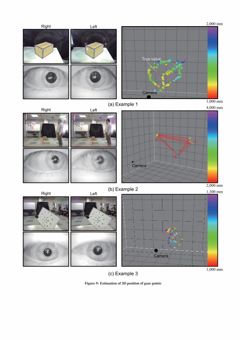
Figure 9: Estimation of 3D position of gaze points