Embed Size (px)
Citation preview

Rev. B 6-3-2015 PAGE 1 OF 12
APPLICABLE MODELS: Full Size trucks with bed lengths of 5.5’ / 6.0’ / 6.5’
Leitner Designs 25675 Taladro Circle Unit E
Mission Viejo, CA 92691 www.leitnerdesigns.com
ACS Instructions
PACKAGE CONTENTS
Driver’s side rail (QTY.1)
Passenger side rail (QTY.1)
Upright A (QTY.2)
Upright B (QTY.2)
Crossbar 60” (QTY.2)
Long bar with T-slot access holes”
(QTY.2)
Hardware
M12 X 40 cap screw (QTY.4)
M8 T-Bolt (QTY.24)
Slide Knob (QTY.4)
M8 locknut (QTY.28)
Crossbar endcap (QTY.4)
Crossbar Pad 60” (QTY.2)
Rivet nut (QTY.6)
(D) (P)
Front upright Brace (QTY.2)
M8 X 20 flange head cap screw (QTY.6)
Cross bar Bracket (QTY.4)
Rail Clamp (QTY.6)
Rear upright Brace bracket (QTY.2)
Rear upright Brace (QTY.2)
M6 X 20 flange head cap screw (QTY.6)
M8 X 60 flange head cap screw (QTY.2)
M8 X 80 cap screw (QTY.6)
Clamp Foot (QTY.6)

Rev. B 6-3-2015 PAGE 2 OF 12
BEFORE INSTALLATION
1) READ ENTIRE INSTRUCTIONS BEFORE PROCEEDING. 2) CLEAN ENTIRE VEHICLE 3) LAY DOWN CARPET OR CARDBOARD TO AVOID SCRATCHING PAINT ON RACK DURING ASSEMBLY
4) MAKE SURE ALL TOOLS ARE AVAILABLE FOR INSTALL.
TORQUE WRENCH TAPE MEASURE
13MM DEEP SOCKET
19MM SOCKET Center Punch RIVET NUT SET
TOOL (INCLUDED)
10MM SOCKET
12MM SOCKET 12MM AND 13MM COMBINATION
WRENCH
3/8 CHUCK ELECTRIC DRILL
25/64 DRILL (INCLUDED)
1
TOOLS REQUIRED
ASSEMBLE DRIVER AND PASSENGER SIDE RAIL ASSEMBLYS
1) INSTALL EIGHT M8 T-BOLTS IN (A) AND (B) UPRIGHTS
AS SHOWN. HAND THREAD WITH M8 LOCKNUT TO KEEP T-NUTS IN PLACE. (FIG 2)
2) INSTALL LONG BAR BY SLIDING INTO UPRIGHT AND
TIGHTEN T-BOLTS TO 16 LB-FT MAKE SURE THE ACCESS HOLES ARE TOWARD THE REAR UPRIGHTS. (FIG 3)
3) INSTALL RAIL USING TWO M12 X 40 BOLTS AS
SHOWN. TIGHTEN TO 55 LB-FT. THE RAILS ARE LABELED AT THE BACK (D) FOR DRIVER AND (P) FOR PASSENGER SIDE. (FIG 4)
4) REPEAT STEPS FOR PASSENGER SIDE
5) A FULL ASSEMBLY IS SHOWN ON PAGE 6 FOR
CLARIFICATION OF ALL ASSEMBLED PARTS.
(fig 4)
Upright B (rear)
Driver’s side shown
Upright A (front)
Long bar access holes
M12 X 40 bolt
(fig 2)
T-BOLT
M8 NUT
Long Bar
Access hole
Rear driver’s rail marked with (D)
(fig 3)

Rev. B 6-3-2015 PAGE 3 OF 12
2
INSTALL FRONT AND REAR UPRIGHT BRACE
1) LOOSLEY INSTALL REAR UPRIGHT BRACE TO REAR UPRIGHT USING (2) M8 X 20 SCREWS AND M8 LOCK NUTS. TIGHTEN SCREWS SO THAT YOU CAN STILL MOVE THE PARTS BY HAND. (FIG 5)
2) LOOSELY ATTACH THE REAR UPRIGHT BRACE
BRACKET TO THE UPRIGHT BRACE USING (1) M8 X 60 SCREW AND (1) M8 LOCKNUT TIGHTEN SCREWS SO THAT YOU CAN STILL MOVE THE PARTS BY HAND. (FIG 6)
3) LOOSELY INSTALL FRONT UPRIGHT BRACE TO FRONT UPRIGHT USING (1) M8 X 20 SCREW AND M8 LOCK NUT. TIGHTEN SCREW SO THAT YOU CAN STILL MOVE THE PARTS BY HAND. (FIG 7)
4) REPEAT STEPS 1-3 FOR OTHER SIDE.
(fig 5)
(fig 6)
Rear upright
Rear
Upright brace
Rear Upright
brace
Upright brace Bracket
(fig 7)
Front upright
Driver’s side shown
Driver’s side shown
`
Front upright
brace

Rev. B 6-3-2015 PAGE 4 OF 12
ATTACH DRIVER AND PASSENGER ASSEMBLYS TO TRUCK
1) LOOSELY THREAD THE (6) M8 X 80 SCREWS INTO THE (6) RAIL CLAMPS AS SHOWN IN (FIG 8)
2) SLIDE 3 RAIL CLAMPS ONTO PASSENGER AND
DRIVERS RAILS, FINISHED IN STEP 3. MAKE SURE THE TAB ON THE CLAMP HOOKS UNDER THE RAIL. (NOTE: SOME TRUCK ONLY HAVE ROOM FOR TWO CLAMPS PER SIDE) (FIG 9)
3) INSTALL ASSEMBLY ONTO TRUCK. (HAVING A
SECOND PERSON STABALIZE THE ASSEMBLY MAKES THIS JOB MUCH EASIER).
4) INSTALL CLAMP FOOT ON ALL 3 RAIL CLAMPS. (FIG 11) TIGHTEN CLAMPS SO THAT THE RAIL STAYS IN PLACE ON THE TRUCK BUT CAN STILL BE MOVED FORWARD AND BACKWARDS.
5) REPEAT FOR OTHER SIDE.
NOTE: SOME BEDLINERS MAY NEED TO BE MODIFIED. CUTTING BEDLINER IN AREA OF RAIL CLAMP MAY BE NECESSARY.
3
Driver’s side shown
Driver’s side shown
(fig 10)
(fig 8)
(fig 9)
Clamp Foot
(fig 11)

Rev. B 6-3-2015 PAGE 5 OF 12
`
4
INSTALL CROSS BAR BRACKETS
`
1) ADJUST THE RACK SO THAT THE SWING TUBE MOUNTING BRACKETS ALIGHNS WITH THE CENTER OF THE D PILLER. INSURE TAILGATE DOES NOT HIT THE BRACKET IN THE CLOSED POSITION (FIG 12)
2) TIGHTEN THE (3) RAIL CLAMPS TO 6 FT-LB
REPEAT FOR OTHER SIDE MAKING SURE THE RAILS ON BOTH SIDES OF THE TRUCK ARE IN THE SAME LOCATION (FRONT TO BACK) USE A TAPE MEASURE TO INSURE LOCATION IS THE SAME ON BOTH PASSENGER AND DRIVERS SIDE +/- 1/8 INCH. (AFTER 500 MILES AND 10,000 MILES THERE AFTER CHECK RAIL CLAMP BOLTS FOR CORRECT TORQUE)
3) INSTALL TWO T-BOLTS AND M8 NUTS INTO EACH OF THE (4) CROSS BAR BRACKETS (FIG 13)
5) SLIDE (4) T-BOLTS INTO THE TOP RAIL USING THE ACCESS HOLES. REPEAT FOR OTHER SIDE.
4) ATTACH (2) OF THE CROSSBAR BRACKET AS FAR FORWARD ON THE RAILS AS POSSIBLE. (ONE ON THE PASSENGER SIDE AND ONE ON THE DRIVERS SIDE). USING TWO M8 NUTS TIGHTEN TO 16 LB-FT. (FIG 14)
5) ATTACH (2) MORE CROSSBAR BRACKET AS
FAR REARWARD ON THE RAILS AS POSSIBLE (ONE ON THE PASSENGER SIDE AND ONE ON THE DRIVERS SIDE. HAND TIGHTEN DOWN USING TWO PLASTIC KNOBS. (FIG 15)
Tailgate
(fig 12)
D-Pillar
(fig 13)
Front of
truck
(fig 14)
(fig 15)
Knob
T-BOLT
M8 NUT
Brackets will touch when all the
way forward

Rev. B 6-3-2015 PAGE 6 OF 12
INSTALL CROSS BARS 5
1) SLIDE THE (2) CROSS BAR 60” ONTO THE T-BOLTS THAT ARE INSTALLD ON THE CROSS BAR BRACKETS. CENTER THE BAR AND LIGHTLY TIGHTEN THE M8 NUTS AS THEY WILL BE ADJUSTED IN A FUTURE STEP. (FIG 16)
2) TAKE MEASURMENT BETWEEN FRONT AND REAR
OF LOWER ALUMINUM T-SLOT RAILS. (FIG 17) RECORD MEASURMENT BELOW. SUBTRACT 18.75” FROM EACH MEASURMENT. THIS IS THE DISTANCE BETWEEN THE PLASTIC ENCAPS ON THE UPRIGHTS. (FIG 18)
3) USING A TAPE MEASURE ADJUST THE DISTANCE
ACCORDINGLY. TIGHTEN THE (8) M8 NUTS THAT HOLD THE CROSS BAR IN PLACE.
DOUBLE CHECK YOUR WORK AS YOU
WILL BE DRILLING HOLES IN THE
NEXT FEW STEPS!!
(fig 16)
MEASURMENT A (FRONT) ________ -18.75 = A1_______
MEASURMENT B (REAR) _______ -18.75 =B1________
A
B
A1
B1
(fig 17) Take measurements from this surface
(fig 18)
Rev. B 6-3-2015 PAGE 7 OF 12
`
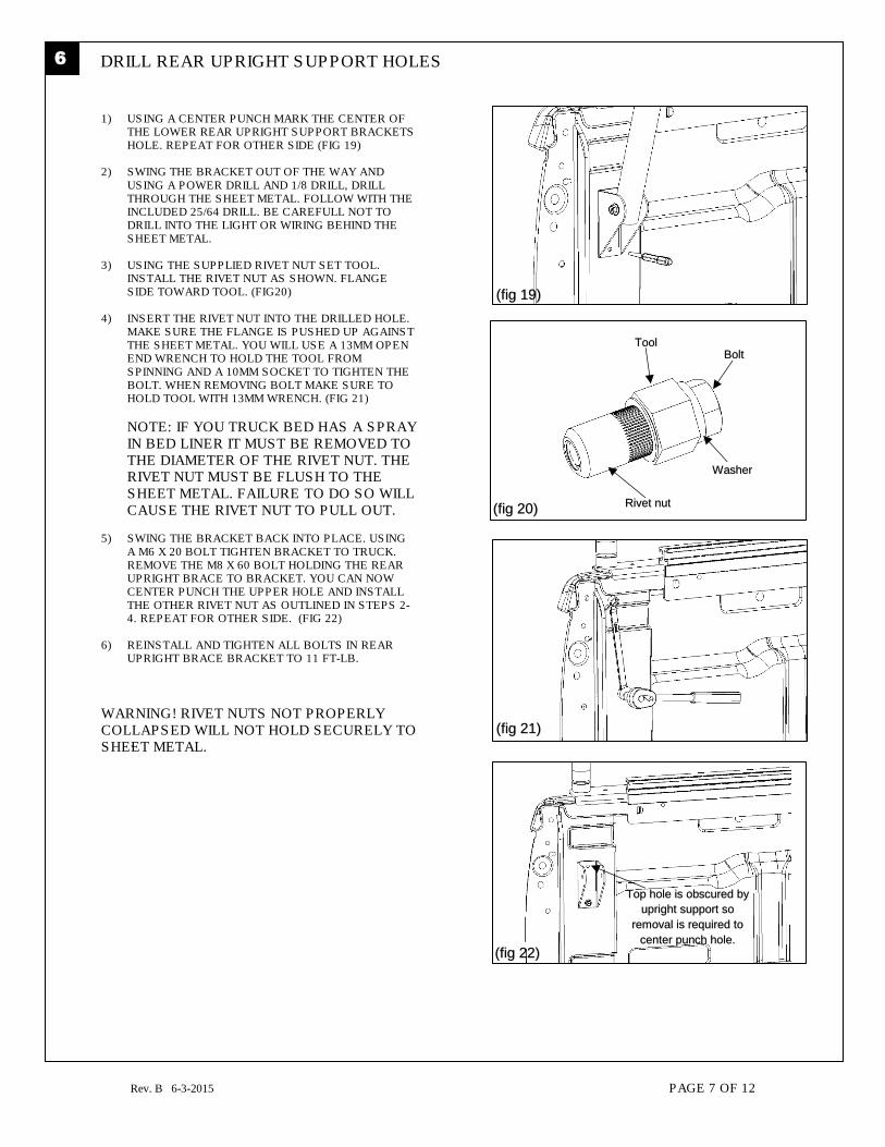
DRILL REAR UPRIGHT SUPPORT HOLES 6
1) USING A CENTER PUNCH MARK THE CENTER OF THE LOWER REAR UPRIGHT SUPPORT BRACKETS HOLE. REPEAT FOR OTHER SIDE (FIG 19)
2) SWING THE BRACKET OUT OF THE WAY AND
USING A POWER DRILL AND 1/8 DRILL, DRILL THROUGH THE SHEET METAL. FOLLOW WITH THE INCLUDED 25/64 DRILL. BE CAREFULL NOT TO DRILL INTO THE LIGHT OR WIRING BEHIND THE SHEET METAL.
3) USING THE SUPPLIED RIVET NUT SET TOOL. INSTALL THE RIVET NUT AS SHOWN. FLANGE SIDE TOWARD TOOL. (FIG20)
4) INSERT THE RIVET NUT INTO THE DRILLED HOLE. MAKE SURE THE FLANGE IS PUSHED UP AGAINST THE SHEET METAL. YOU WILL USE A 13MM OPEN END WRENCH TO HOLD THE TOOL FROM SPINNING AND A 10MM SOCKET TO TIGHTEN THE BOLT. WHEN REMOVING BOLT MAKE SURE TO HOLD TOOL WITH 13MM WRENCH. (FIG 21)
NOTE: IF YOU TRUCK BED HAS A SPRAY IN BED LINER IT MUST BE REMOVED TO THE DIAMETER OF THE RIVET NUT. THE RIVET NUT MUST BE FLUSH TO THE SHEET METAL. FAILURE TO DO SO WILL CAUSE THE RIVET NUT TO PULL OUT.
5) SWING THE BRACKET BACK INTO PLACE. USING A M6 X 20 BOLT TIGHTEN BRACKET TO TRUCK. REMOVE THE M8 X 60 BOLT HOLDING THE REAR UPRIGHT BRACE TO BRACKET. YOU CAN NOW CENTER PUNCH THE UPPER HOLE AND INSTALL THE OTHER RIVET NUT AS OUTLINED IN STEPS 2-4. REPEAT FOR OTHER SIDE. (FIG 22)
6) REINSTALL AND TIGHTEN ALL BOLTS IN REAR UPRIGHT BRACE BRACKET TO 11 FT-LB.
WARNING! RIVET NUTS NOT PROPERLY COLLAPSED WILL NOT HOLD SECURELY TO SHEET METAL.
(fig 19)
(fig 20)
(fig 21)
Washer
ToolBolt
Rivet nut
Top hole is obscured by
upright support so
removal is required to
center punch hole.
(fig 22)

Rev. B 6-3-2015 PAGE 8 OF 12
7
DRILL FRONT UPRIGHT SUPPORT HOLES
1) ALIGN THE FRONT UPRIGHT BRACES WITH THE FRONT OF THE CARGO BED RAIL. CENTER PUNCH BOTH BRACKET HOLES. PILOT DRILL WITH A 1/8 DRILL AND THEN DRILL WITH 25/64 DRILL (INCLUDED). (FIG23)
2) INSTALL RIVET NUTS THE SAME WAY AS YOU DID
IN PREVIOUS STEP.
3) SECURE EACH BRACKET WITH M6 X 20 BOLT. TIGHTEN TO 14 FT-LB. (FIG 24)
4) TIGHTEN UPPER FRONT UPRIGHT BRACE BRACKET BOLT AND NUT TO 18 FT-LB. (FIG 25)
NOTE: IT IS NORMAL FOR THE FRONT SUPPORT BRACKETS TO BEND SLIGHTLY. NOTE: BE CAREFULL NOT TO PUSH ON THE DRILL SO HARD AS TO DRILL INTO THE BACK OF THE TRUCK CAB.
(fig 23)
Drill into center of
this rail.
(fig 24)
(fig 25)
Tighten this nut
and bolt assembly

Rev. B 6-3-2015 PAGE 9 OF 12
8 INSURE REAR CROSSBAR SLIDES AND FINISH INSTALLATION
1) LOOSEN THE 4 PLASTIC KNOBS ON THE REAR
CROSS BAR AND SLIDE RAIL FORWARD.( FIG 26)
2) IF IT DOES NOT SLIDE ALL THE WAY FORWARD
LOOSEN THE FOUR NUTS SECURING THE RAIL TO
THE BRACKETS AND SLIDE INTO MOST
FORWARD POSITION UNTIL BOTH BRACKETS
TOUCH. RETIGHTEN NUTS WHILE KEEPING
CROSS BAR AND BRACKETS IN FORWARD
POSITION. (FIG27)
3) INSTALL (2) CROSSBAR PAD AND (4) ENDCAPS AS
SHOWN. (FIG 28)
4) SLIDE THE CROSSBAR BACK INTO THE
REARWARD POSITION.
5) CONGRATULATIONS YOU ARE NOW READY TO
MAXIMIZE THE CARGO CARING CAPACITY OF
YOUR TRUCK! PLEASE CHECK OUT THE MANY
ACCESSORIES AT WWW.LEITNERDESIGNS.COM
(fig 26)
(fig 27)
Loosen these 4 nuts.
Touch brackets together
(fig 28)

Rev. B 6-3-2015 PAGE 10 OF 12
Rear Passenger upright (A)
Rear Driver
upright (B)
Front Passenger
upright (B)

Rev. B 6-3-2015 PAGE 11 OF 12
When using Leitner Designs carriers and accessories, the user must understand the precautions. The points listed below will assist you in using the rack system and will encourage safety.
• For quality fits and safety, use only the recommended rack or accessories. Do not assume a rack will fit, always check the current Fit Guide when obtaining a new vehicle.
• The maximum load is not to be exceeded. (250# off road – 500# on road). However, this limit is always subordinate to the maximum load recommended by the manufacturer of the vehicle itself. It is always the lower maximum recommended load that applies. Max truck load = load carrier weight + any fitted carrier accessories + the weight of the load itself.
• Make sure all knobs, bolts, screws, straps, and locks are firmly attached, tightened and locked before every trip. Knobs, bolts, screws, straps and locks must be periodically inspected for signs of wear, corrosion, and fatigue. Check your load at stops during the trip to ensure continued fastening security.
• Check local and state laws governing projection of objects beyond the perimeter of a vehicle. Be aware of the width and height of your cargo since low clearance branches, bridges, and parking garages can affect the load. All cargo will affect the vehicle’s driving behavior. Never drive with any lock, knob or rack in an open or unlocked position. All long loads such as, but not limited to, sailboards, surfboards, kayaks, canoes, and lumber must be tied down front and rear to the bumpers or tow hooks of the vehicle.
• All locks must be turned and moved periodically to ensure smooth operation. Use graphite or dry lubricant to help this. Leitner designs locks are designed to deter vandalism and theft but should not be considered theft proof. Remove valuable gear if your vehicle is unattended for an extended period. Place at least one key in the glove compartment.
• For safety to your vehicle and rack system, obey all posted speed limits and traffic cautions. Adapt your speed to the conditions of the road and the load being carried.
• Do not use Leitner Designs load carriers and accessories for purposes other than those for which they were designed. Do not exceed their carrying capacity. Failure to follow these guidelines or the product’s instructions will void the warranty.
• Consult with your Leitner Designs dealer if you have any questions regarding the operations and limits of Thule products. Review all instructions and warranty information carefully.
Rev. B 6-3-2015 PAGE 12 OF 12
Leitner Designs warrants product to be free from defects in material and workmanship, for terms specified below, provided there has been normal use and proper maintenance. All remedies under this warranty are limited to the repair or replacement of any item found by the factory to be defective within the time period specified. If you have a warranty claim, first you must call our factory at the number below for instructions. You must retain proof of purchase and submit a copy with any items returned for warranty work. Upon completion of warranty work, if any, we will return the repaired or replaced item or items to you freight prepaid. Damage to our products caused by accidents, Fire, vandalism, negligence, misinstallation, misuse, Acts of God, or by defective parts not manufactured by us, is not covered under this warranty. THE WARRANTY TIME PERIOD IS AS FOLLOWS: (2) TWO YEARS FROM DATE OF PURCHASE. ANY IMPLIED WARRANTIES OF MERCHANTABILITY AND/OR FITNESS FOR A PARTICULAR PURPOSE CREATED HEREBY ARE LIMITED IN DURATION TO THE SAME DURATION AND SCOPE AS THE EXPRESS WRITTEN WARRANTY. OUR COMPANY SHALL NOT BE LIABLE FOR ANY INCIDENTAL OR CONSEQUENTIAL DAMAGE. Some states do not allow limitations on how long an implied warranty lasts, or the exclusion or limitation of incidental or consequential damages, so the above limitations or exclusions may not apply to you. This warranty gives you specific legal rights, and you may also have other rights that vary from state to state. FOR WARRANTY ISSUES WITH THIS PRODUCT PLEASE CALL LEITNER DESIGNS CUSTOMER SERVICE 949-395-3049 Be sure to read and precisely follow the provided instructions when installing this product. Failure to do so could place the vehicle occupants in a potentially dangerous situation. After installing or reinstalling, re-check to insure that the product is properly installed.