Embed Size (px)
Citation preview
advanced coated system
Fixed Bearing Surgical TechniqueDistal Femur Cut First
4 in 1 Femur Preparation
acs®
knee system

Nota Bene: The surgical technique described herein shows the treatment suggested by the author with uncomplicated interferences. However, it is ultimately the operating surgeon’s decision, which approach is the most meaningful and effective for the respective patient.
Copyright Information: Cepthar®, ACS®, ACCIS®, DiaLoc®, EcoFit®, Aida®, MUTARS® and LOAD SHIFT®, implavit®, implacross® and impla-tan® are registered trademarks of implantcast GmbH. The use and copying of the contents of this brochure, also in part, is only permitted with prior
consent from implantcast GmbH.
1
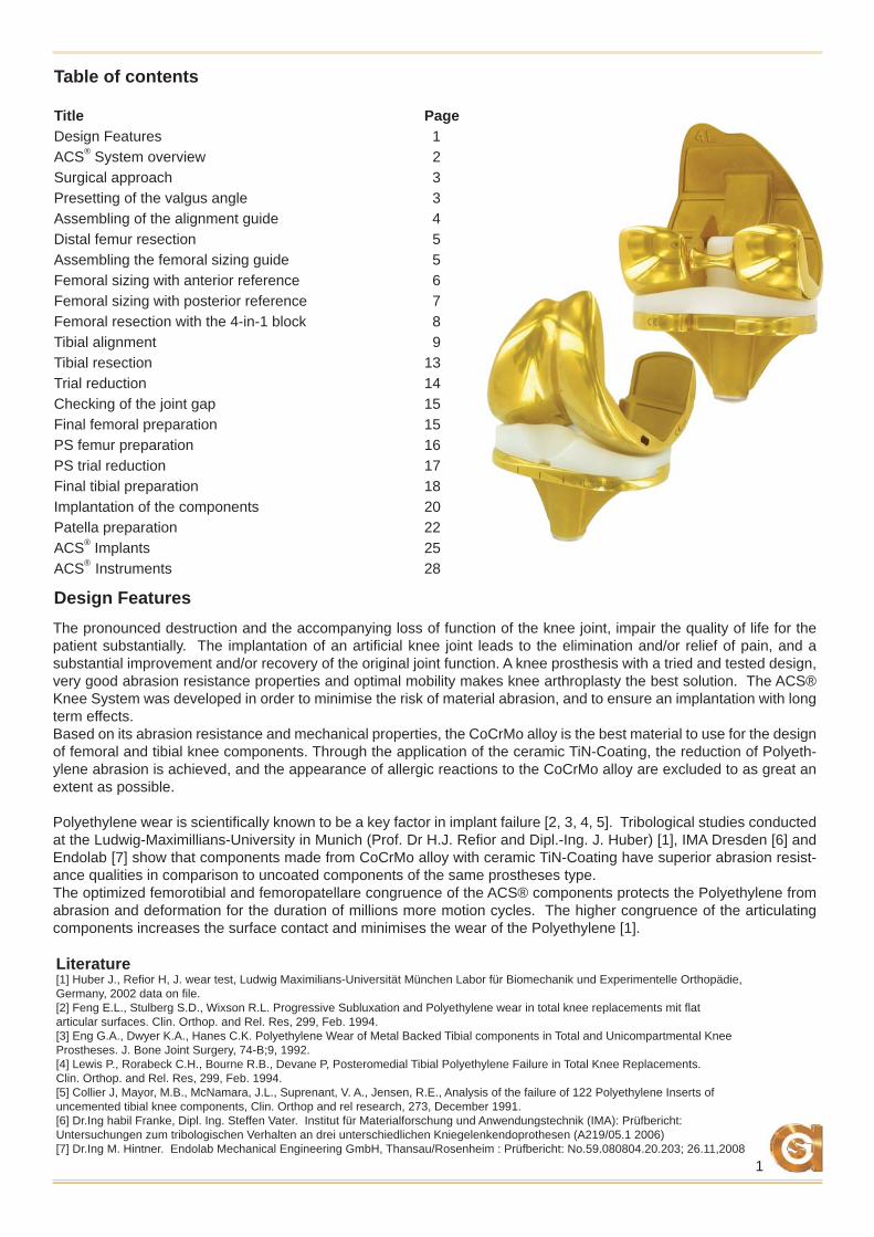
Table of contents
Title PageDesign Features 1ACS® System overview 2Surgical approach 3Presetting of the valgus angle 3Assembling of the alignment guide 4Distal femur resection 5Assembling the femoral sizing guide 5Femoral sizing with anterior reference 6Femoral sizing with posterior reference 7Femoral resection with the 4-in-1 block 8Tibial alignment 9Tibial resection 13Trial reduction 14Checking of the joint gap 15Final femoral preparation 15PS femur preparation 16PS trial reduction 17Final tibial preparation 18Implantation of the components 20Patella preparation 22ACS® Implants 25ACS® Instruments 28
Design FeaturesThe pronounced destruction and the accompanying loss of function of the knee joint, impair the quality of life for the patient substantially. The implantation of an artifi cial knee joint leads to the elimination and/or relief of pain, and a substantial improvement and/or recovery of the original joint function. A knee prosthesis with a tried and tested design, very good abrasion resistance properties and optimal mobility makes knee arthroplasty the best solution. The ACS® Knee System was developed in order to minimise the risk of material abrasion, and to ensure an implantation with long term effects.Based on its abrasion resistance and mechanical properties, the CoCrMo alloy is the best material to use for the design of femoral and tibial knee components. Through the application of the ceramic TiN-Coating, the reduction of Polyeth-ylene abrasion is achieved, and the appearance of allergic reactions to the CoCrMo alloy are excluded to as great an extent as possible.
Polyethylene wear is scientifi cally known to be a key factor in implant failure [2, 3, 4, 5]. Tribological studies conducted at the Ludwig-Maximillians-University in Munich (Prof. Dr H.J. Refi or and Dipl.-Ing. J. Huber) [1], IMA Dresden [6] and Endolab [7] show that components made from CoCrMo alloy with ceramic TiN-Coating have superior abrasion resist-ance qualities in comparison to uncoated components of the same prostheses type.The optimized femorotibial and femoropatellare congruence of the ACS® components protects the Polyethylene from abrasion and deformation for the duration of millions more motion cycles. The higher congruence of the articulating components increases the surface contact and minimises the wear of the Polyethylene [1].
Literature[1] Huber J., Refi or H, J. wear test, Ludwig Maximilians-Universität München Labor für Biomechanik und Experimentelle Orthopädie, Germany, 2002 data on fi le.[2] Feng E.L., Stulberg S.D., Wixson R.L. Progressive Subluxation and Polyethylene wear in total knee replacements mit fl at articular surfaces. Clin. Orthop. and Rel. Res, 299, Feb. 1994.[3] Eng G.A., Dwyer K.A., Hanes C.K. Polyethylene Wear of Metal Backed Tibial components in Total and Unicompartmental Knee Prostheses. J. Bone Joint Surgery, 74-B;9, 1992.[4] Lewis P., Rorabeck C.H., Bourne R.B., Devane P, Posteromedial Tibial Polyethylene Failure in Total Knee Replacements. Clin. Orthop. and Rel. Res, 299, Feb. 1994.[5] Collier J, Mayor, M.B., McNamara, J.L., Suprenant, V. A., Jensen, R.E., Analysis of the failure of 122 Polyethylene Inserts of uncemented tibial knee components, Clin. Orthop and rel research, 273, December 1991.[6] Dr.Ing habil Franke, Dipl. Ing. Steffen Vater. Institut für Materialforschung und Anwendungstechnik (IMA): Prüfbericht: Untersuchungen zum tribologischen Verhalten an drei unterschiedlichen Kniegelenkendoprothesen (A219/05.1 2006)[7] Dr.Ing M. Hintner. Endolab Mechanical Engineering GmbH, Thansau/Rosenheim : Prüfbericht: No.59.080804.20.203; 26.11,2008
2
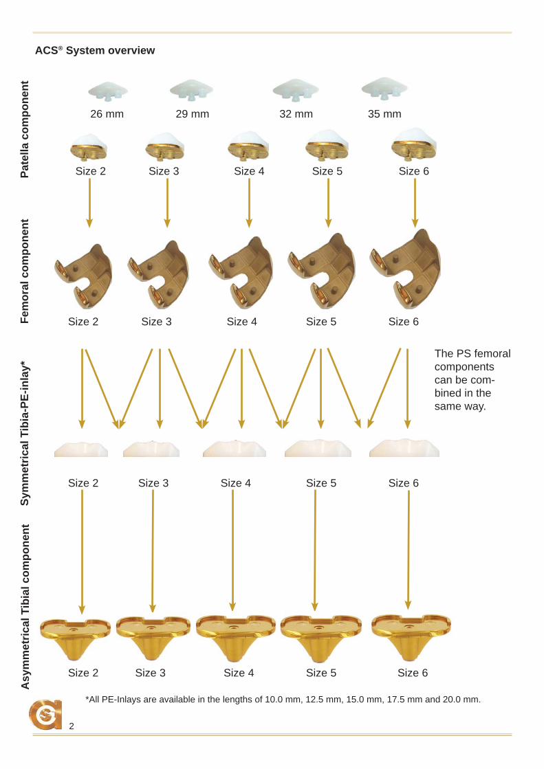
ACS® System overview
26 mm 29 mm 32 mm 35 mm
Pate
lla c
ompo
nent
Asy
mm
etric
al T
ibia
l com
pone
nt
Size 2 Size 3 Size 4 Size 5 Size 6
Size 2 Size 3 Size 4 Size 5 Size 6
Size 2 Size 3 Size 4 Size 5 Size 6
Size 2 Size 3 Size 4 Size 5 Size 6
*All PE-Inlays are available in the lengths of 10.0 mm, 12.5 mm, 15.0 mm, 17.5 mm and 20.0 mm.
Sym
met
rical
Tib
ia-P
E-in
lay*
Fe
mor
al c
ompo
nent
The PS femoral components can be com-bined in the same way.
3
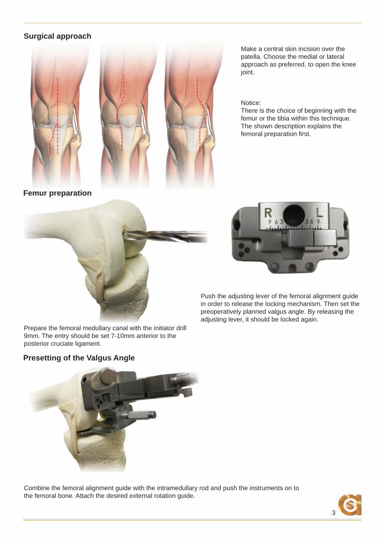
Surgical approach
Femur preparation
Presetting of the Valgus Angle
Make a central skin incision over the patella. Choose the medial or lateral approach as preferred, to open the knee joint.
Push the adjusting lever of the femoral alignment guide in order to release the locking mechanism. Then set the preoperatively planned valgus angle. By releasing the adjusting lever, it should be locked again.
Combine the femoral alignment guide with the intramedullary rod and push the instruments on to the femoral bone. Attach the desired external rotation guide.
Prepare the femoral medullary canal with the initiator drill 9mm. The entry should be set 7-10mm anterior to the posterior cruciate ligament.
Notice:There is the choice of beginning with the femur or the tibia within this technique. The shown description explains the femoral preparation fi rst.
4
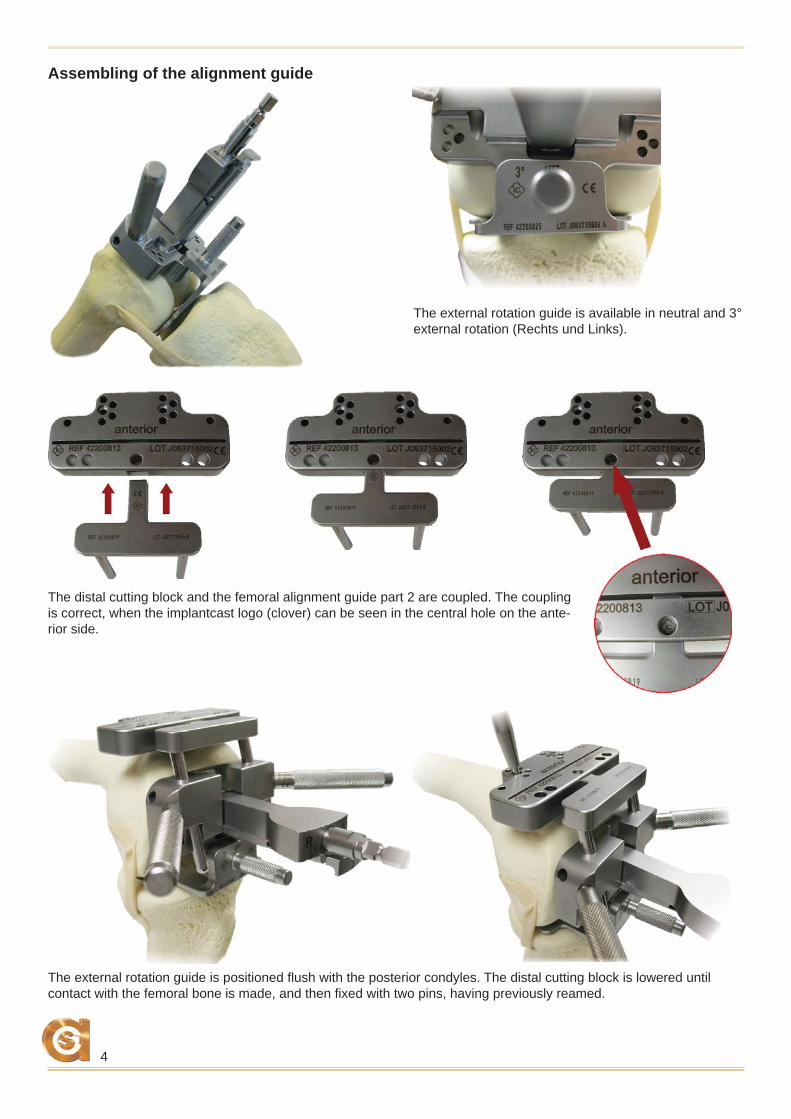
The distal cutting block and the femoral alignment guide part 2 are coupled. The coupling is correct, when the implantcast logo (clover) can be seen in the central hole on the ante-rior side.
The external rotation guide is positioned fl ush with the posterior condyles. The distal cutting block is lowered until contact with the femoral bone is made, and then fi xed with two pins, having previously reamed.
The external rotation guide is available in neutral and 3° external rotation (Rechts und Links).
Assembling of the alignment guide
5
AC
BD
A
B
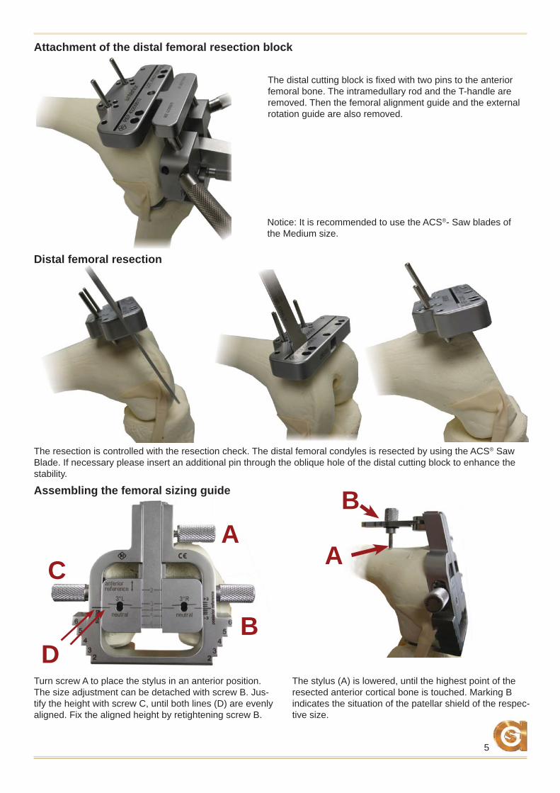
The resection is controlled with the resection check. The distal femoral condyles is resected by using the ACS® Saw Blade. If necessary please insert an additional pin through the oblique hole of the distal cutting block to enhance the stability.
Distal femoral resection
The distal cutting block is fi xed with two pins to the anterior femoral bone. The intramedullary rod and the T-handle are removed. Then the femoral alignment guide and the external rotation guide are also removed.
Turn screw A to place the stylus in an anterior position. The size adjustment can be detached with screw B. Jus-tify the height with screw C, until both lines (D) are evenly aligned. Fix the aligned height by retightening screw B.
The stylus (A) is lowered, until the highest point of the resected anterior cortical bone is touched. Marking B indicates the situation of the patellar shield of the respec-tive size.
Assembling the femoral sizing guide
Attachment of the distal femoral resection block
Notice: It is recommended to use the ACS®- Saw blades of the Medium size.
6
A
BC
C B
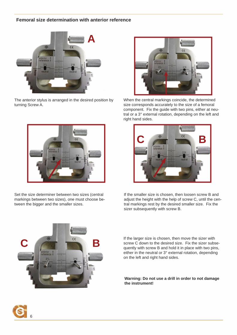
Femoral size determination with anterior reference
The anterior stylus is arranged in the desired position by turning Screw A.
When the central markings coincide, the determined size corresponds accurately to the size of a femoral component. Fix the guide with two pins, either at neu-tral or a 3° external rotation, depending on the left and right hand sides.
Set the size determiner between two sizes (central markings between two sizes), one must choose be-tween the bigger and the smaller sizes.
If the larger size is chosen, then move the sizer with screw C down to the desired size. Fix the sizer subse-quently with screw B and hold it in place with two pins, either in the neutral or 3° external rotation, depending on the left and right hand sides.
If the smaller size is chosen, then loosen screw B and adjust the height with the help of screw C, until the cen-tral markings rest by the desired smaller size. Fix the sizer subsequently with screw B.
Warning: Do not use a drill in order to not damage the instrument!
7
A
B
C B
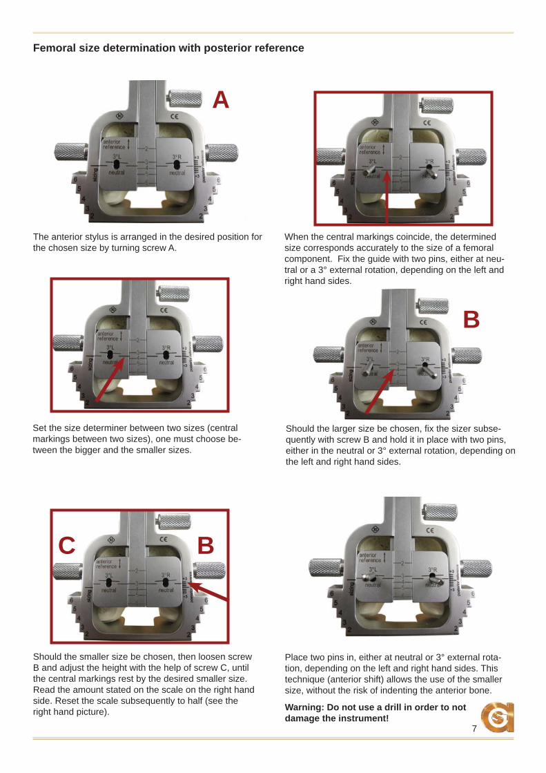
Femoral size determination with posterior reference
The anterior stylus is arranged in the desired position for the chosen size by turning screw A.
When the central markings coincide, the determined size corresponds accurately to the size of a femoral component. Fix the guide with two pins, either at neu-tral or a 3° external rotation, depending on the left and right hand sides.
Should the smaller size be chosen, then loosen screw B and adjust the height with the help of screw C, until the central markings rest by the desired smaller size. Read the amount stated on the scale on the right hand side. Reset the scale subsequently to half (see the right hand picture).
Place two pins in, either at neutral or 3° external rota-tion, depending on the left and right hand sides. This technique (anterior shift) allows the use of the smaller size, without the risk of indenting the anterior bone.
Set the size determiner between two sizes (central markings between two sizes), one must choose be-tween the bigger and the smaller sizes.
Should the larger size be chosen, fi x the sizer subse-quently with screw B and hold it in place with two pins, either in the neutral or 3° external rotation, depending on the left and right hand sides.
Warning: Do not use a drill in order to not damage the instrument!
8
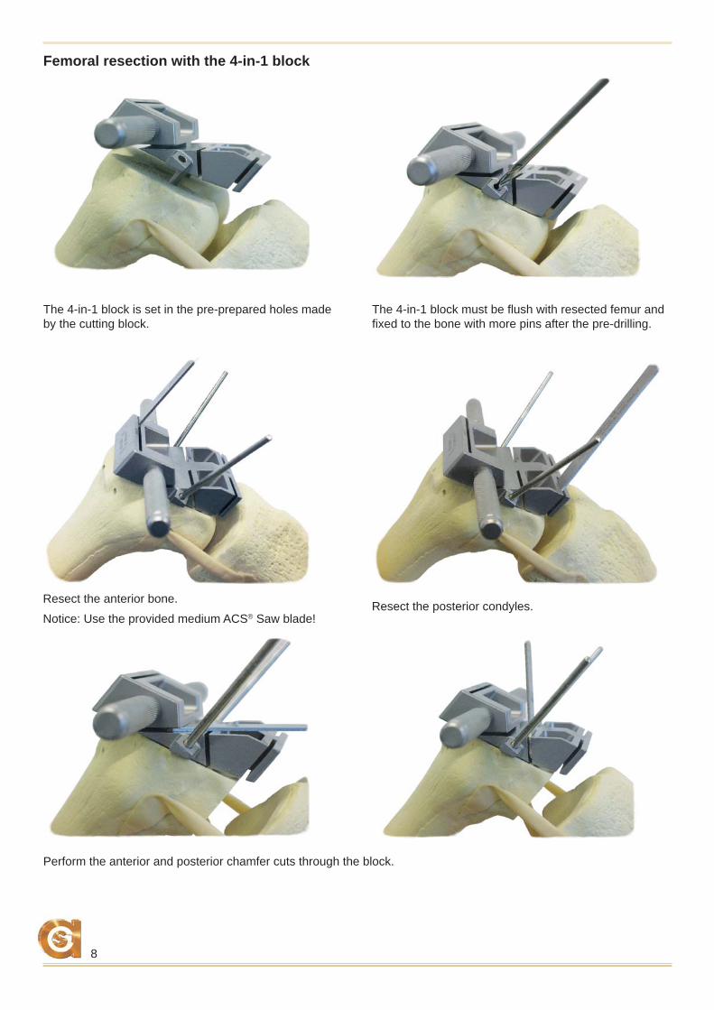
The 4-in-1 block is set in the pre-prepared holes made by the cutting block.
The 4-in-1 block must be fl ush with resected femur and fi xed to the bone with more pins after the pre-drilling.
Resect the anterior bone. Resect the posterior condyles.
Perform the anterior and posterior chamfer cuts through the block.
Femoral resection with the 4-in-1 block
Notice: Use the provided medium ACS® Saw blade!
9
1
4
3
2
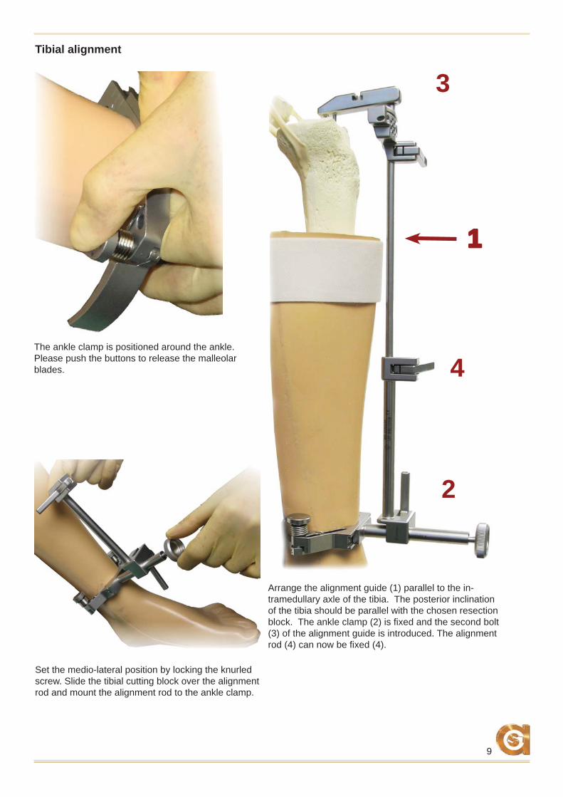
The ankle clamp is positioned around the ankle.Please push the buttons to release the malleolar blades.
Tibial alignment
Arrange the alignment guide (1) parallel to the in-tramedullary axle of the tibia. The posterior inclination of the tibia should be parallel with the chosen resection block. The ankle clamp (2) is fi xed and the second bolt (3) of the alignment guide is introduced. The alignment rod (4) can now be fi xed (4).
Set the medio-lateral position by locking the knurled screw. Slide the tibial cutting block over the alignment rod and mount the alignment rod to the ankle clamp.
10
BA
1
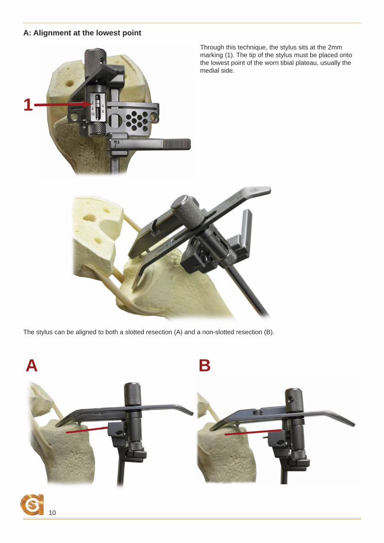
The stylus can be aligned to both a slotted resection (A) and a non-slotted resection (B).
A: Alignment at the lowest point
Through this technique, the stylus sits at the 2mm marking (1). The tip of the stylus must be placed onto the lowest point of the worn tibial plateau, usually the medial side.
11
2
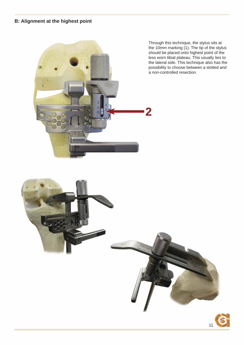
B: Alignment at the highest point
Through this technique, the stylus sits at the 10mm marking (1). The tip of the stylus should be placed onto highest point of the less worn tibial plateau. This usually lies to the lateral side. This technique also has the possibility to choose between a slotted and a non-controlled resection.
12
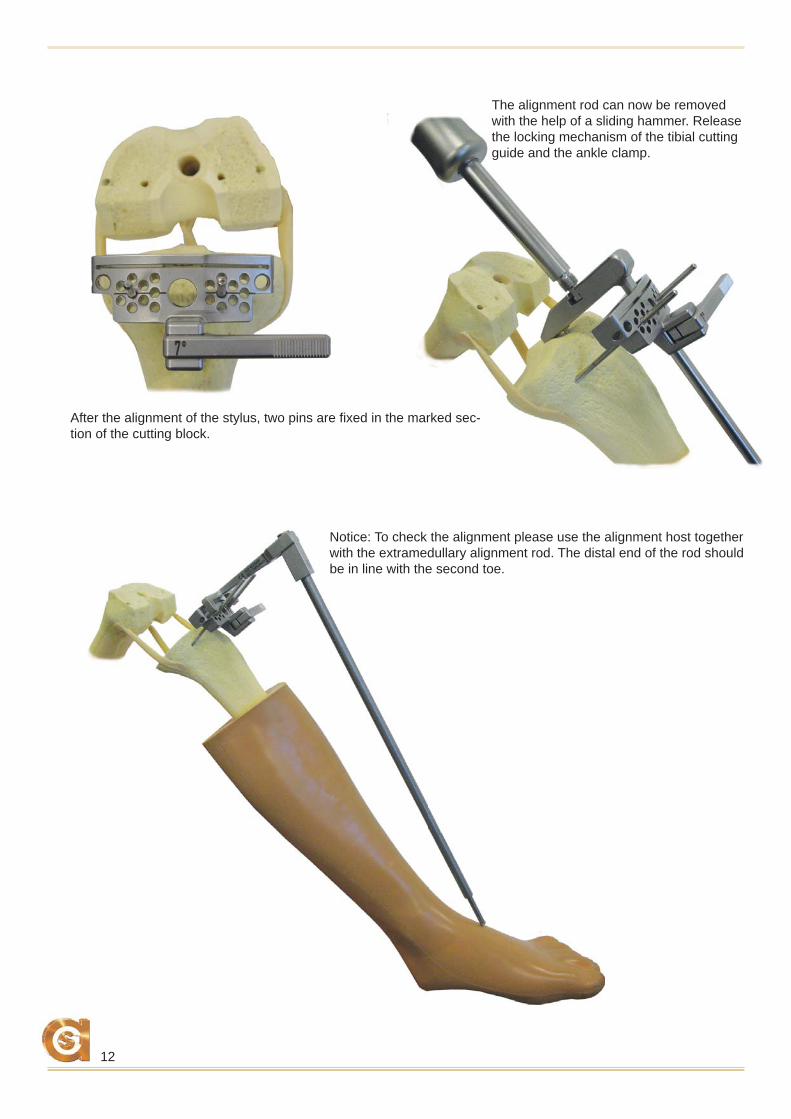
After the alignment of the stylus, two pins are fi xed in the marked sec-tion of the cutting block.
Notice: To check the alignment please use the alignment host together with the extramedullary alignment rod. The distal end of the rod should be in line with the second toe.
The alignment rod can now be removed with the help of a sliding hammer. Release the locking mechanism of the tibial cutting guide and the ankle clamp.
13
A B
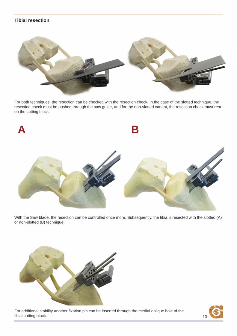
With the Saw blade, the resection can be controlled once more. Subsequently, the tibia is resected with the slotted (A) or non-slotted (B) technique.
Tibial resection
For both techniques, the resection can be checked with the resection check. In the case of the slotted technique, the resection check must be pushed through the saw guide, and for the non-slotted variant, the resection check must rest on the cutting block.
For additional stability another fi xation pin can be inserted through the medial oblique hole of the tibial cutting block.
14
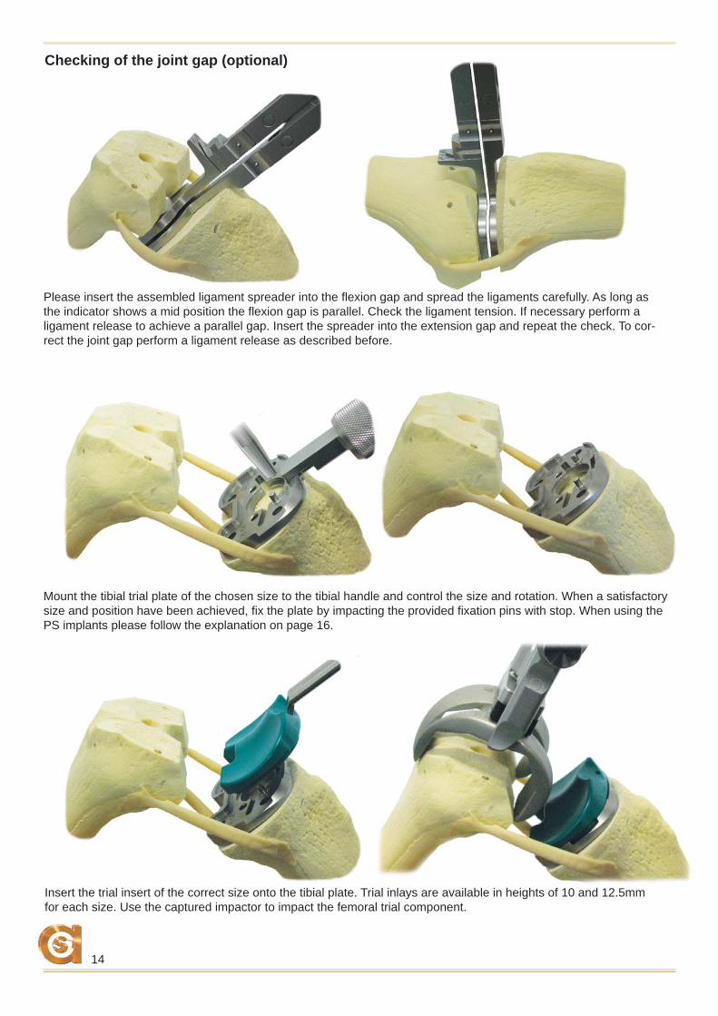
Mount the tibial trial plate of the chosen size to the tibial handle and control the size and rotation. When a satisfactory size and position have been achieved, fi x the plate by impacting the provided fi xation pins with stop. When using the PS implants please follow the explanation on page 16.
Insert the trial insert of the correct size onto the tibial plate. Trial inlays are available in heights of 10 and 12.5mm for each size. Use the captured impactor to impact the femoral trial component.
Checking of the joint gap (optional)
Please insert the assembled ligament spreader into the fl exion gap and spread the ligaments carefully. As long as the indicator shows a mid position the fl exion gap is parallel. Check the ligament tension. If necessary perform a ligament release to achieve a parallel gap. Insert the spreader into the extension gap and repeat the check. To cor-rect the joint gap perform a ligament release as described before.
15
Trial reduction
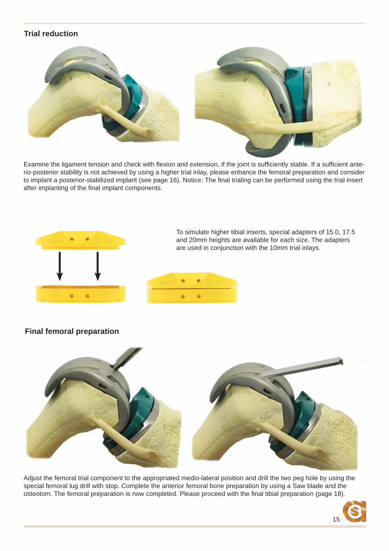
Examine the ligament tension and check with fl exion and extension, if the joint is suffi ciently stable. If a suffi cient ante-rio-posterior stability is not achieved by using a higher trial inlay, please enhance the femoral preparation and consider to implant a posterior-stabilized implant (see page 16). Notice: The fi nal trialing can be performed using the trial insert after implanting of the fi nal implant components.
Adjust the femoral trial component to the appropriated medio-lateral position and drill the two peg hole by using the special femoral lug drill with stop. Complete the anterior femoral bone preparation by using a Saw blade and the osteotom. The femoral preparation is now completed. Please proceed with the fi nal tibial preparation (page 18).
Final femoral preparation
To simulate higher tibial inserts, special adapters of 15.0, 17.5 and 20mm heights are available for each size. The adapters are used in conjunction with the 10mm trial inlays.
16
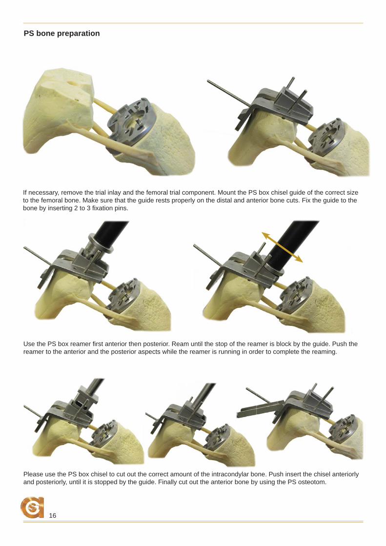
PS bone preparation
If necessary, remove the trial inlay and the femoral trial component. Mount the PS box chisel guide of the correct size to the femoral bone. Make sure that the guide rests properly on the distal and anterior bone cuts. Fix the guide to the bone by inserting 2 to 3 fi xation pins.
Please use the PS box chisel to cut out the correct amount of the intracondylar bone. Push insert the chisel anteriorly and posteriorly, until it is stopped by the guide. Finally cut out the anterior bone by using the PS osteotom.
Use the PS box reamer fi rst anterior then posterior. Ream until the stop of the reamer is block by the guide. Push the reamer to the anterior and the posterior aspects while the reamer is running in order to complete the reaming.
17
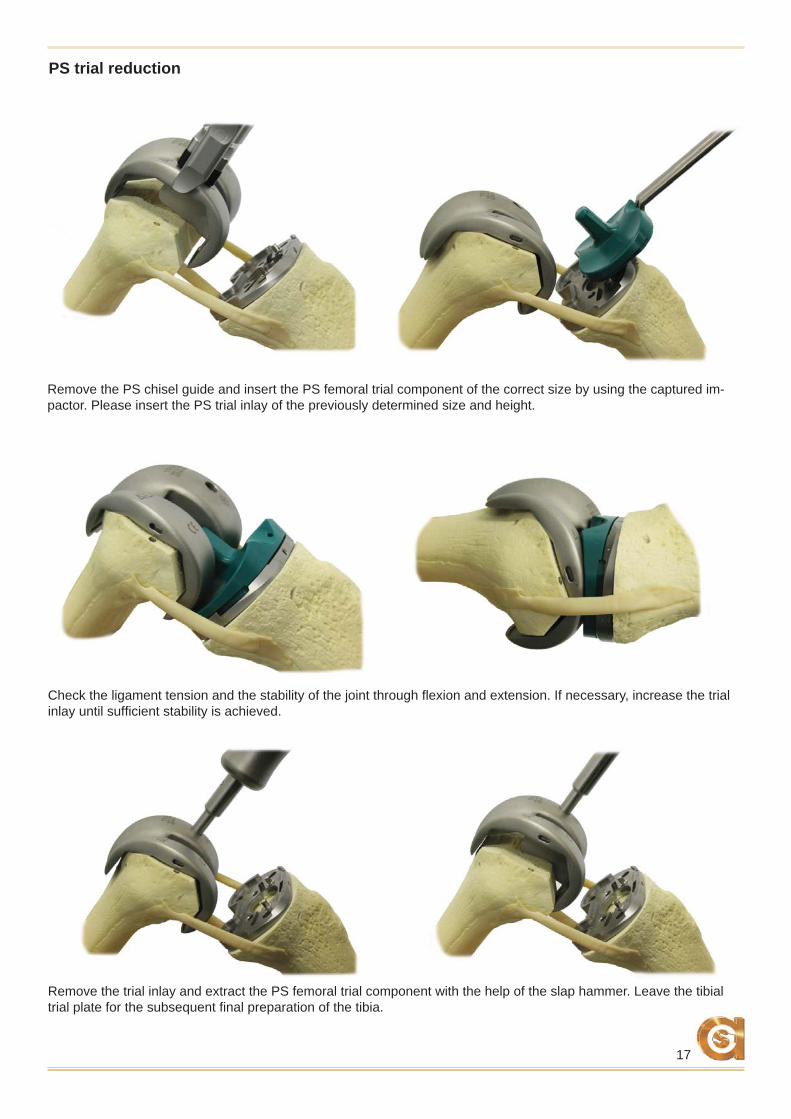
PS trial reduction
Check the ligament tension and the stability of the joint through fl exion and extension. If necessary, increase the trial inlay until suffi cient stability is achieved.
Remove the trial inlay and extract the PS femoral trial component with the help of the slap hammer. Leave the tibial trial plate for the subsequent fi nal preparation of the tibia.
Remove the PS chisel guide and insert the PS femoral trial component of the correct size by using the captured im-pactor. Please insert the PS trial inlay of the previously determined size and height.
18
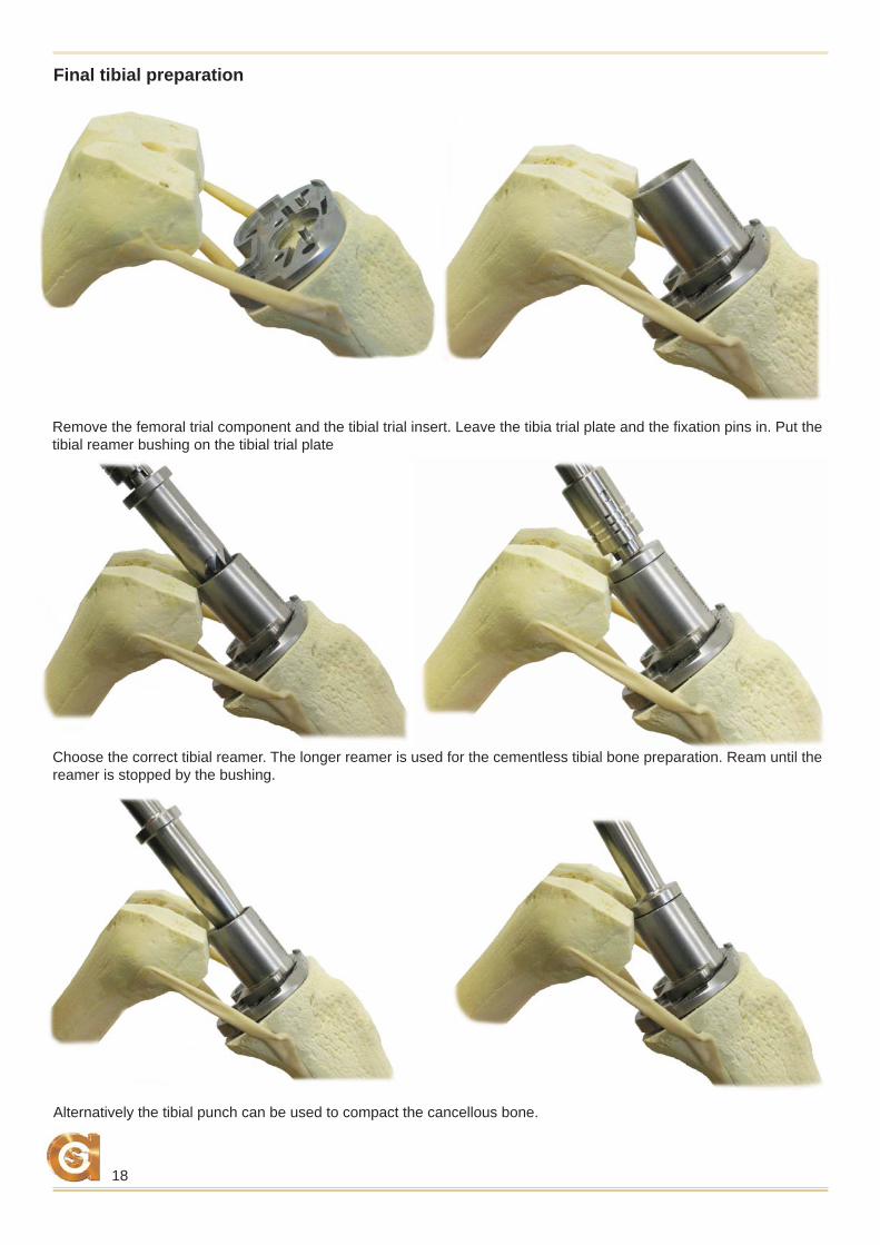
Choose the correct tibial reamer. The longer reamer is used for the cementless tibial bone preparation. Ream until the reamer is stopped by the bushing.
Alternatively the tibial punch can be used to compact the cancellous bone.
Remove the femoral trial component and the tibial trial insert. Leave the tibia trial plate and the fi xation pins in. Put the tibial reamer bushing on the tibial trial plate
Final tibial preparation
19
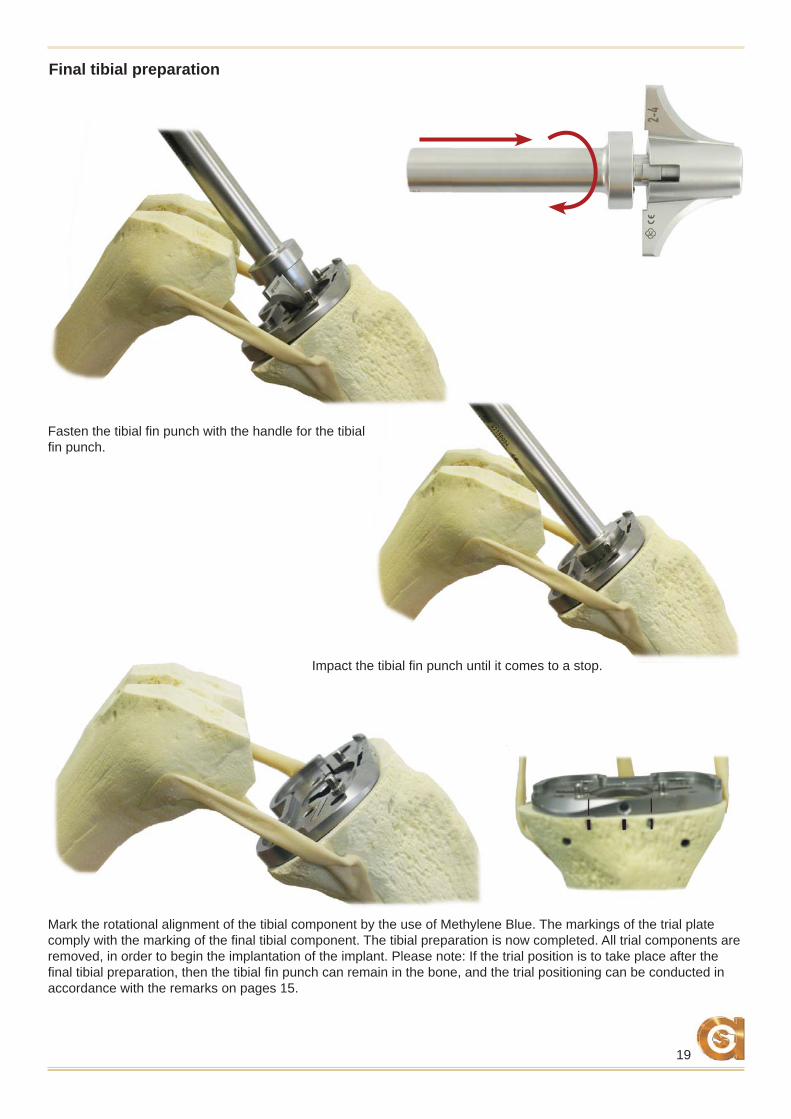
Fasten the tibial fi n punch with the handle for the tibial fi n punch.
Impact the tibial fi n punch until it comes to a stop.
Final tibial preparation
Mark the rotational alignment of the tibial component by the use of Methylene Blue. The markings of the trial plate comply with the marking of the fi nal tibial component. The tibial preparation is now completed. All trial components are removed, in order to begin the implantation of the implant. Please note: If the trial position is to take place after the fi nal tibial preparation, then the tibial fi n punch can remain in the bone, and the trial positioning can be conducted in accordance with the remarks on pages 15.
20
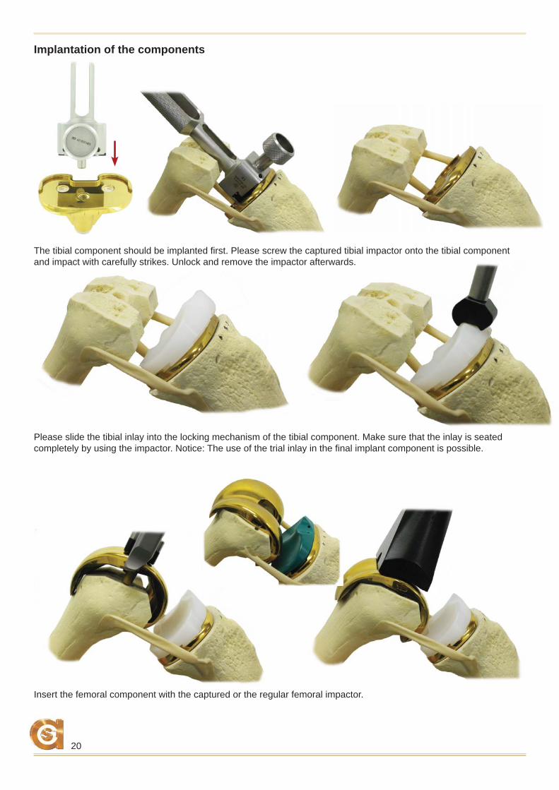
The tibial component should be implanted fi rst. Please screw the captured tibial impactor onto the tibial component and impact with carefully strikes. Unlock and remove the impactor afterwards.
Implantation of the components
Insert the femoral component with the captured or the regular femoral impactor.
Please slide the tibial inlay into the locking mechanism of the tibial component. Make sure that the inlay is seated completely by using the impactor. Notice: The use of the trial inlay in the fi nal implant component is possible.
21
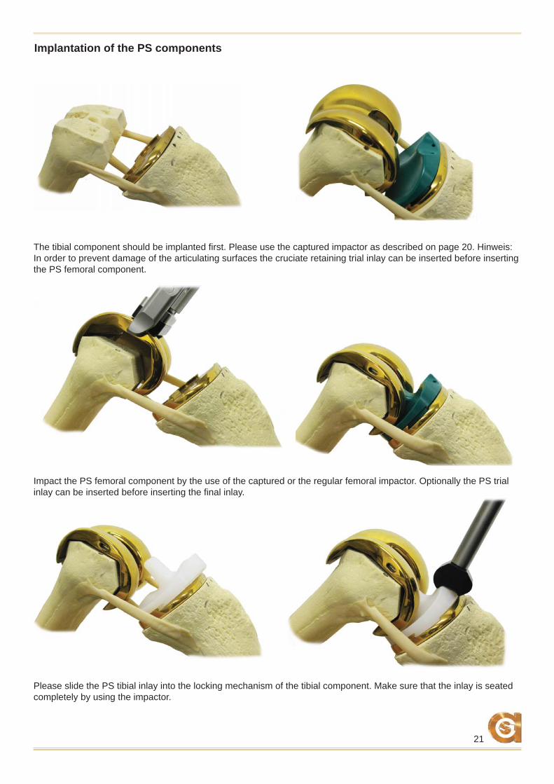
Implantation of the PS components
The tibial component should be implanted fi rst. Please use the captured impactor as described on page 20. Hinweis: In order to prevent damage of the articulating surfaces the cruciate retaining trial inlay can be inserted before inserting the PS femoral component.
Please slide the PS tibial inlay into the locking mechanism of the tibial component. Make sure that the inlay is seated completely by using the impactor.
Impact the PS femoral component by the use of the captured or the regular femoral impactor. Optionally the PS trial inlay can be inserted before inserting the fi nal inlay.
22
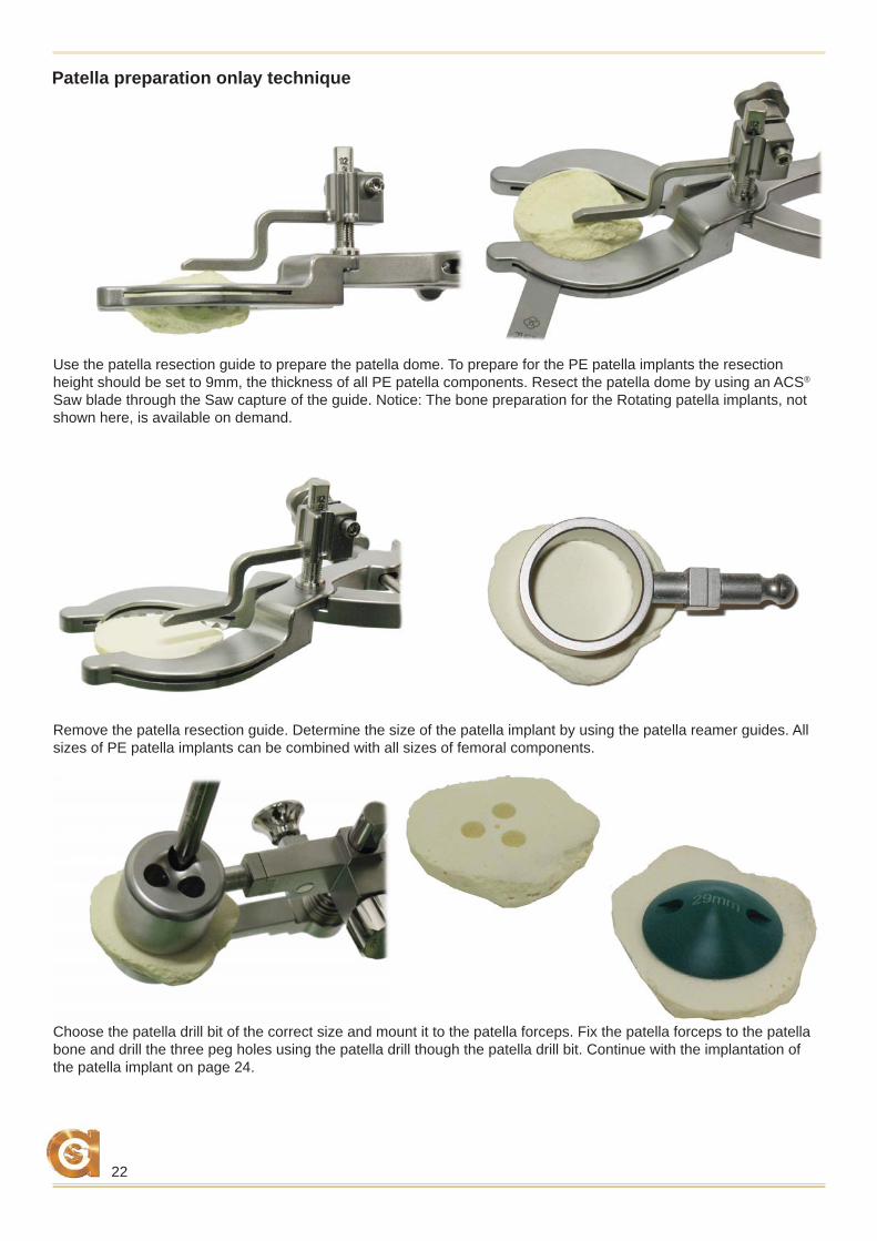
Remove the patella resection guide. Determine the size of the patella implant by using the patella reamer guides. All sizes of PE patella implants can be combined with all sizes of femoral components.
Choose the patella drill bit of the correct size and mount it to the patella forceps. Fix the patella forceps to the patella bone and drill the three peg holes using the patella drill though the patella drill bit. Continue with the implantation of the patella implant on page 24.
Use the patella resection guide to prepare the patella dome. To prepare for the PE patella implants the resection height should be set to 9mm, the thickness of all PE patella components. Resect the patella dome by using an ACS® Saw blade through the Saw capture of the guide. Notice: The bone preparation for the Rotating patella implants, not shown here, is available on demand.
Patella preparation onlay technique
23
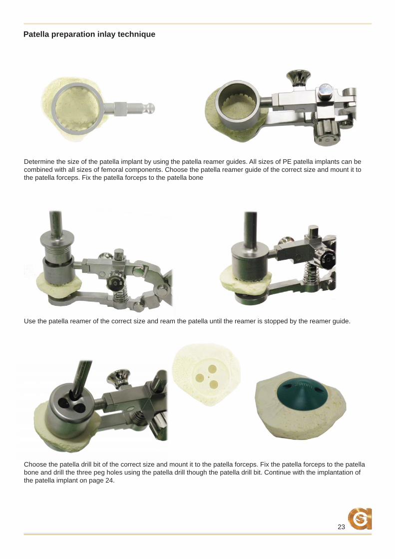
Determine the size of the patella implant by using the patella reamer guides. All sizes of PE patella implants can be combined with all sizes of femoral components. Choose the patella reamer guide of the correct size and mount it to the patella forceps. Fix the patella forceps to the patella bone
Choose the patella drill bit of the correct size and mount it to the patella forceps. Fix the patella forceps to the patella bone and drill the three peg holes using the patella drill though the patella drill bit. Continue with the implantation of the patella implant on page 24.
Use the patella reamer of the correct size and ream the patella until the reamer is stopped by the reamer guide.
Patella preparation inlay technique
24
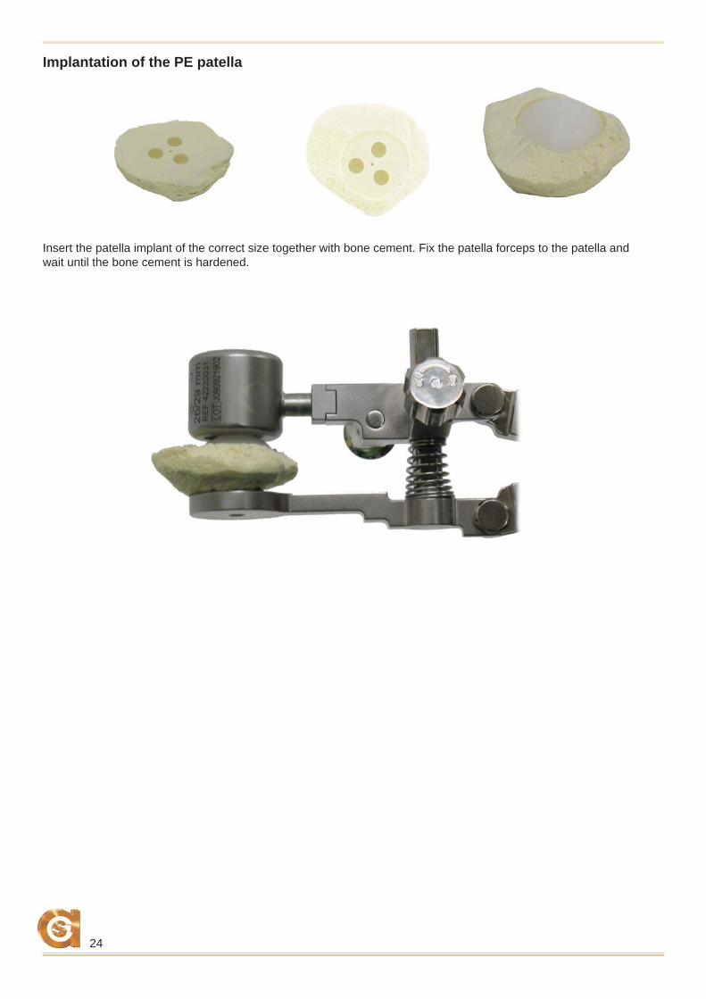
Insert the patella implant of the correct size together with bone cement. Fix the patella forceps to the patella and wait until the bone cement is hardened.
Implantation of the PE patella
25
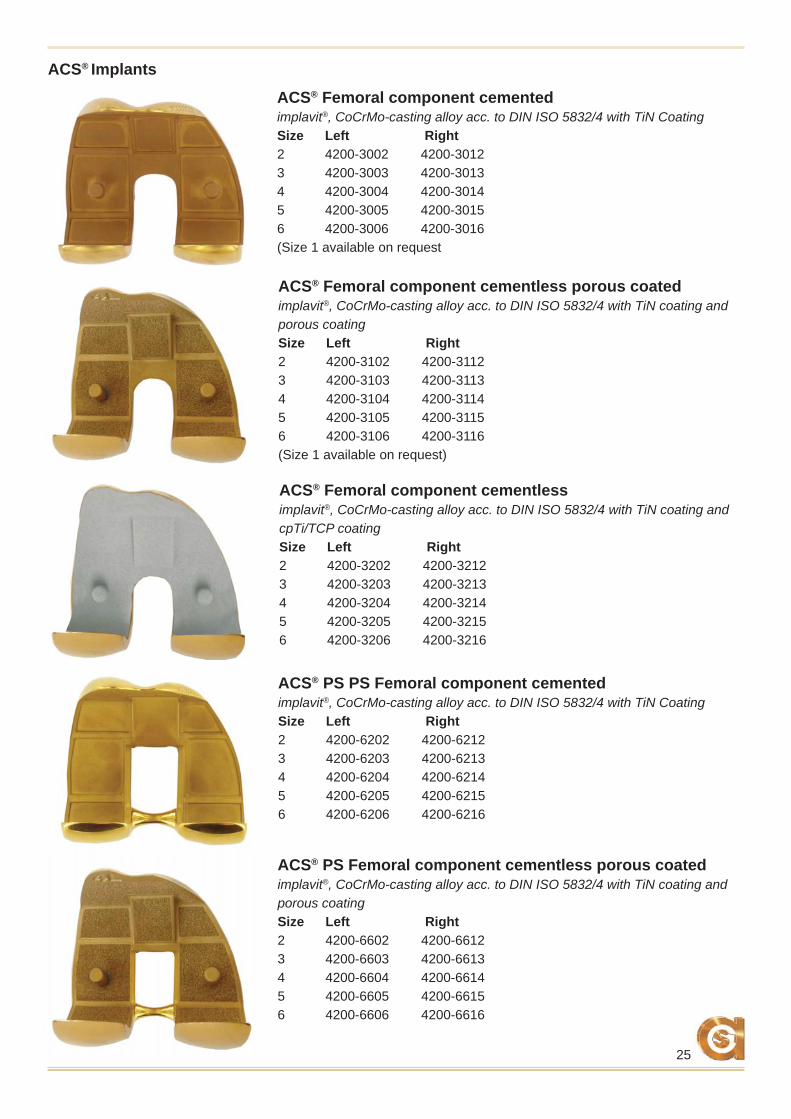
ACS® Femoral component cemented implavit®, CoCrMo-casting alloy acc. to DIN ISO 5832/4 with TiN CoatingSize Left Right2 4200-3002 4200-30123 4200-3003 4200-30134 4200-3004 4200-30145 4200-3005 4200-30156 4200-3006 4200-3016(Size 1 available on request
ACS® Femoral component cementless porous coatedimplavit®, CoCrMo-casting alloy acc. to DIN ISO 5832/4 with TiN coating and porous coatingSize Left Right2 4200-3102 4200-31123 4200-3103 4200-31134 4200-3104 4200-31145 4200-3105 4200-31156 4200-3106 4200-3116(Size 1 available on request)
ACS® Femoral component cementlessimplavit®, CoCrMo-casting alloy acc. to DIN ISO 5832/4 with TiN coating and cpTi/TCP coatingSize Left Right2 4200-3202 4200-32123 4200-3203 4200-32134 4200-3204 4200-32145 4200-3205 4200-32156 4200-3206 4200-3216
ACS® Implants
ACS® PS PS Femoral component cementedimplavit®, CoCrMo-casting alloy acc. to DIN ISO 5832/4 with TiN CoatingSize Left Right2 4200-6202 4200-62123 4200-6203 4200-62134 4200-6204 4200-62145 4200-6205 4200-62156 4200-6206 4200-6216
ACS® PS Femoral component cementless porous coatedimplavit®, CoCrMo-casting alloy acc. to DIN ISO 5832/4 with TiN coating and porous coatingSize Left Right2 4200-6602 4200-66123 4200-6603 4200-66134 4200-6604 4200-66145 4200-6605 4200-66156 4200-6606 4200-6616
26
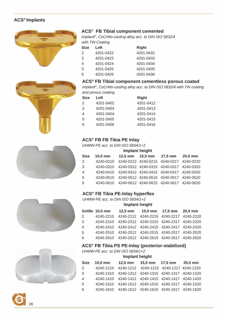
ACS® FB Tibial component cementedimplavit®, CoCrMo-casting alloy acc. to DIN ISO 5832/4 with TiN CoatingSize Left Right2 4201-0422 4201-04323 4201-0423 4201-04334 4201-0424 4201-04345 4201-0425 4201-04356 4201-0426 4201-0436
ACS® FB Tibial component cementless porous coatedimplavit®, CoCrMo-casting alloy acc. to DIN ISO 5832/4 with TiN coating and porous coatingSize Left Right2 4201-0402 4201-04123 4201-0403 4201-04134 4201-0404 4201-04145 4201-0405 4201-04156 4201-0406 4201-0416
ACS® Implants
ACS® FB FB Tibia PE Inlay UHMW-PE acc. to DIN ISO 5834/1+2 Implant heightSize 10,0 mm 12,5 mm 15,0 mm 17,5 mm 20,0 mm2 4240-0210 4240-0212 4240-0215 4240-0217 4240-02203 4240-0310 4240-0312 4240-0315 4240-0317 4240-03204 4240-0410 4240-0412 4240-0415 4240-0417 4240-04205 4240-0510 4240-0512 4240-0515 4240-0517 4240-05206 4240-0610 4240-0612 4240-0615 4240-0617 4240-0620
Größe 10,0 mm 12,5 mm 15,0 mm 17,5 mm 20,0 mm2 4240-2210 4240-2212 4240-2215 4240-2217 4240-22203 4240-2310 4240-2312 4240-2315 4240-2317 4240-23204 4240-2410 4240-2412 4240-2415 4240-2417 4240-24205 4240-2510 4240-2512 4240-2515 4240-2517 4240-25206 4240-2610 4240-2612 4240-2615 4240-2617 4240-2620
ACS® FB Tibia PE-Inlay hyperfl exUHMW-PE acc. to DIN ISO 5834/1+2 Implant height
Size 10,0 mm 12,5 mm 15,0 mm 17,5 mm 20,0 mm2 4240-1210 4240-1212 4240-1215 4240-1217 4240-12203 4240-1310 4240-1312 4240-1315 4240-1317 4240-13204 4240-1410 4240-1412 4240-1415 4240-1417 4240-14205 4240-1510 4240-1512 4240-1515 4240-1517 4240-15206 4240-1610 4240-1612 4240-1615 4240-1617 4240-1620
ACS® FB Tibia PS PE-Inlay (posterior-stabilized)UHMW-PE acc. to DIN ISO 5834/1+2 Implant height
27
ACS® Implants
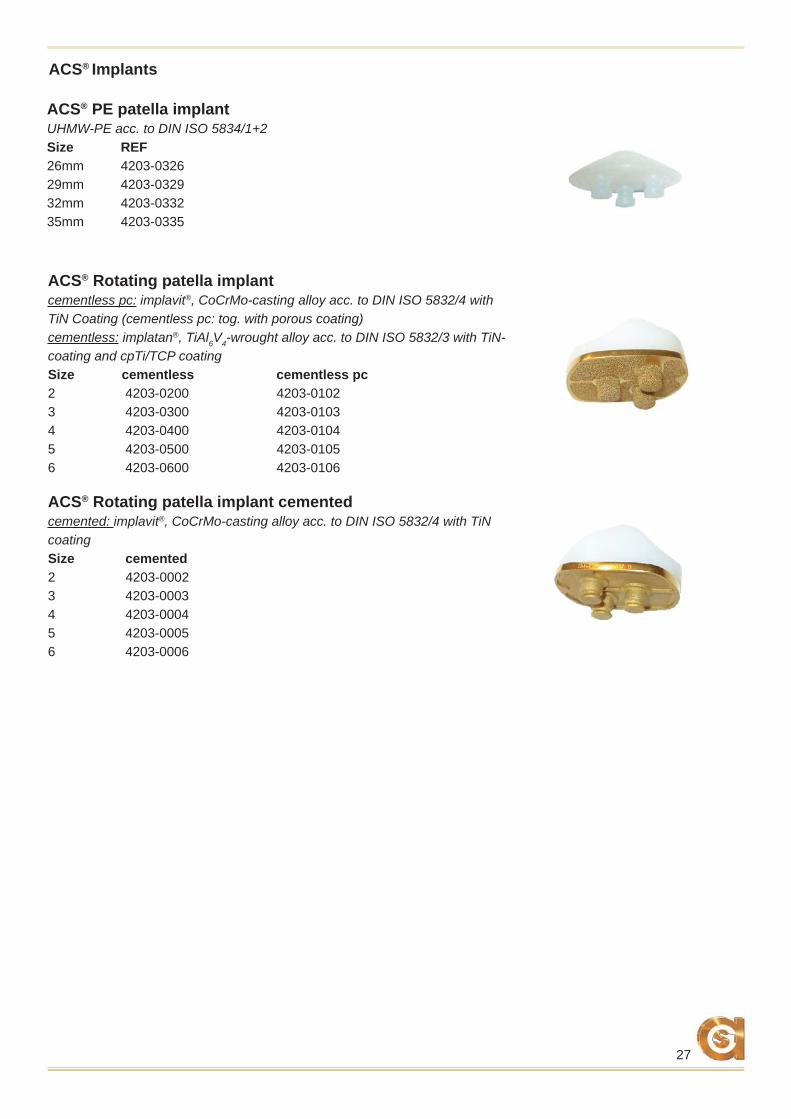
ACS® Rotating patella implantcementless pc: implavit®, CoCrMo-casting alloy acc. to DIN ISO 5832/4 with TiN Coating (cementless pc: tog. with porous coating) cementless: implatan®, TiAl6V4-wrought alloy acc. to DIN ISO 5832/3 with TiN-coating and cpTi/TCP coatingSize cementless cementless pc 2 4203-0200 4203-0102 3 4203-0300 4203-0103 4 4203-0400 4203-0104 5 4203-0500 4203-0105 6 4203-0600 4203-0106
ACS® PE patella implantUHMW-PE acc. to DIN ISO 5834/1+2Size REF 26mm 4203-032629mm 4203-032932mm 4203-033235mm 4203-0335
ACS® Rotating patella implant cementedcemented: implavit®, CoCrMo-casting alloy acc. to DIN ISO 5832/4 with TiN coatingSize cemented2 4203-00023 4203-00034 4203-00045 4203-00056 4203-0006
28
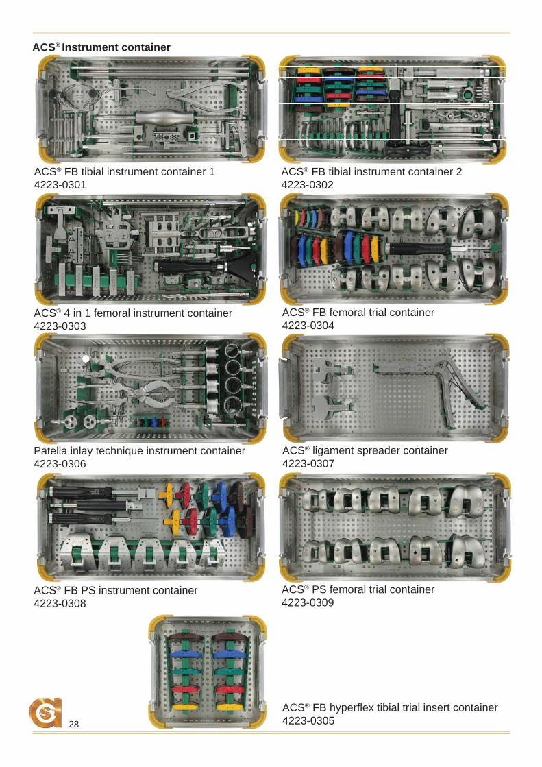
ACS® FB tibial instrument container 1 4223-0301
ACS® FB tibial instrument container 2 4223-0302
ACS® 4 in 1 femoral instrument container 4223-0303
ACS® FB femoral trial container4223-0304
Patella inlay technique instrument container 4223-0306
ACS® Instrument container
ACS® ligament spreader container 4223-0307
ACS® FB PS instrument container4223-0308
ACS® PS femoral trial container 4223-0309
ACS® FB hyperfl ex tibial trial insert container4223-0305
29
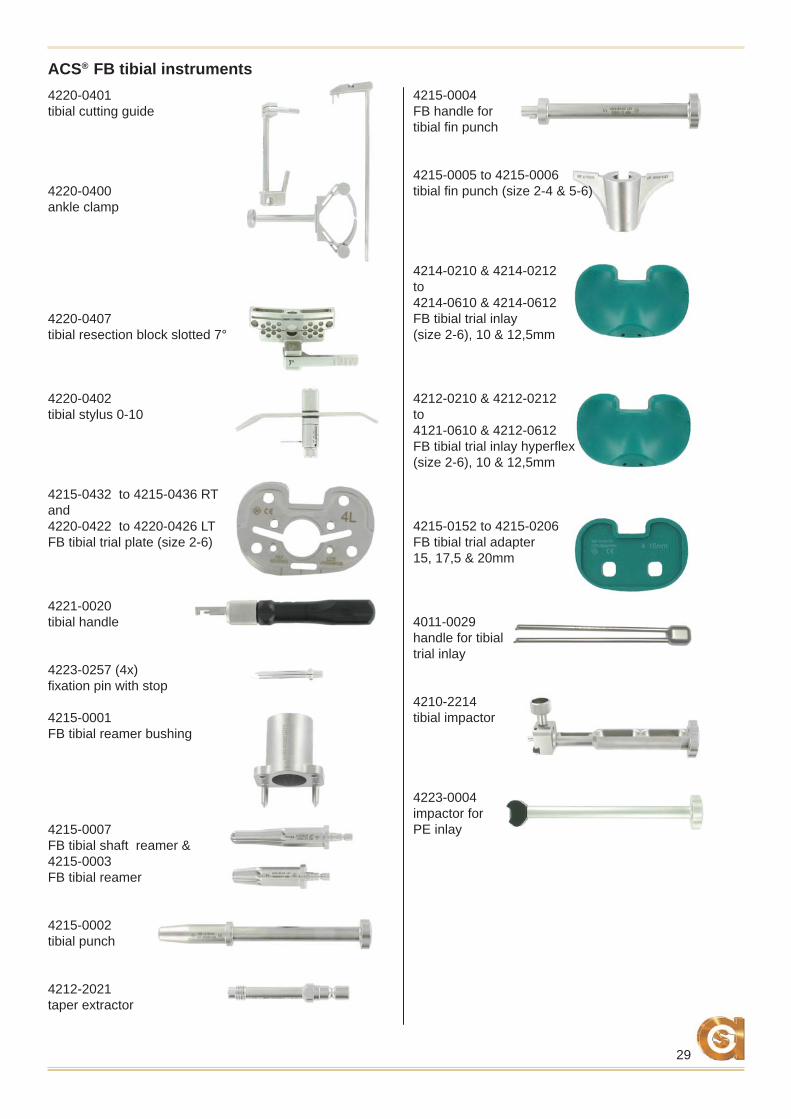
4215-0004FB handle fortibial fi n punch
4215-0005 to 4215-0006tibial fi n punch (size 2-4 & 5-6)
4214-0210 & 4214-0212to 4214-0610 & 4214-0612FB tibial trial inlay(size 2-6), 10 & 12,5mm
4212-0210 & 4212-0212 to 4121-0610 & 4212-0612FB tibial trial inlay hyperfl ex(size 2-6), 10 & 12,5mm
4215-0152 to 4215-0206FB tibial trial adapter 15, 17,5 & 20mm
4011-0029handle for tibial trial inlay
4210-2214tibial impactor
4223-0004impactor forPE inlay
4220-0401 tibial cutting guide
4220-0400 ankle clamp
4220-0407tibial resection block slotted 7°
4220-0402tibial stylus 0-10
4215-0432 to 4215-0436 RTand4220-0422 to 4220-0426 LTFB tibial trial plate (size 2-6)
4221-0020tibial handle
4223-0257 (4x)fi xation pin with stop
4215-0001FB tibial reamer bushing
4215-0007FB tibial shaft reamer &4215-0003 FB tibial reamer
4215-0002tibial punch
4212-2021taper extractor
ACS® FB tibial instruments
30
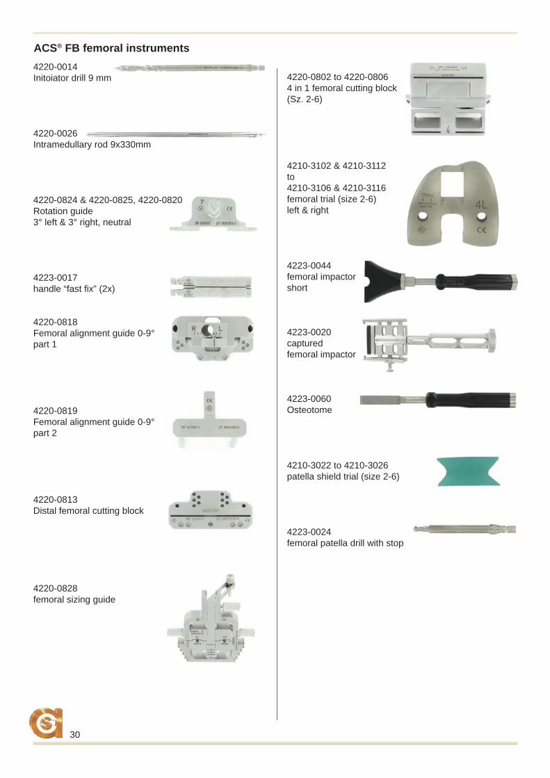
ACS® FB femoral instruments4220-0014Initoiator drill 9 mm
4220-0026Intramedullary rod 9x330mm
4220-0824 & 4220-0825, 4220-0820Rotation guide 3° left & 3° right, neutral
4223-0017handle “fast fi x” (2x)
4220-0818Femoral alignment guide 0-9° part 1
4220-0819Femoral alignment guide 0-9° part 2
4220-0813Distal femoral cutting block
4220-0828femoral sizing guide
4220-0802 to 4220-08064 in 1 femoral cutting block (Sz. 2-6)
4210-3102 & 4210-3112to4210-3106 & 4210-3116femoral trial (size 2-6)left & right
4223-0044femoral impactorshort
4223-0020captured femoral impactor
4223-0060Osteotome
4210-3022 to 4210-3026patella shield trial (size 2-6)
4223-0024femoral patella drill with stop
31
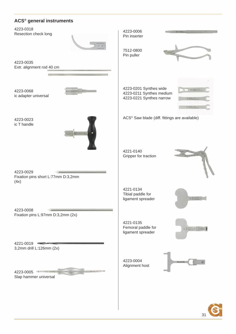
4223-0006Pin inserter
7512-0800Pin puller
4223-0201 Synthes wide4223-0211 Synthes medium4223-0221 Synthes narrow
ACS® Saw blade (diff. fi ttings are available)
4221-0140Gripper for traction
4221-0134Tibial paddle for ligament spreader
4221-0135Femoral paddle for ligament spreader
4223-0004Alignment host
ACS® general instruments4223-0318Resection check long
4223-0035Extr. alignment rod 40 cm
4223-0068ic adapter universal
4223-0023ic T handle
4223-0029Fixation pins short L:77mm D:3,2mm (4x)
4223-0008 Fixation pins L:97mm D:3,2mm (2x)
4221-00193,2mm drill L:126mm (2x)
4223-0005Slap hammer universal
32
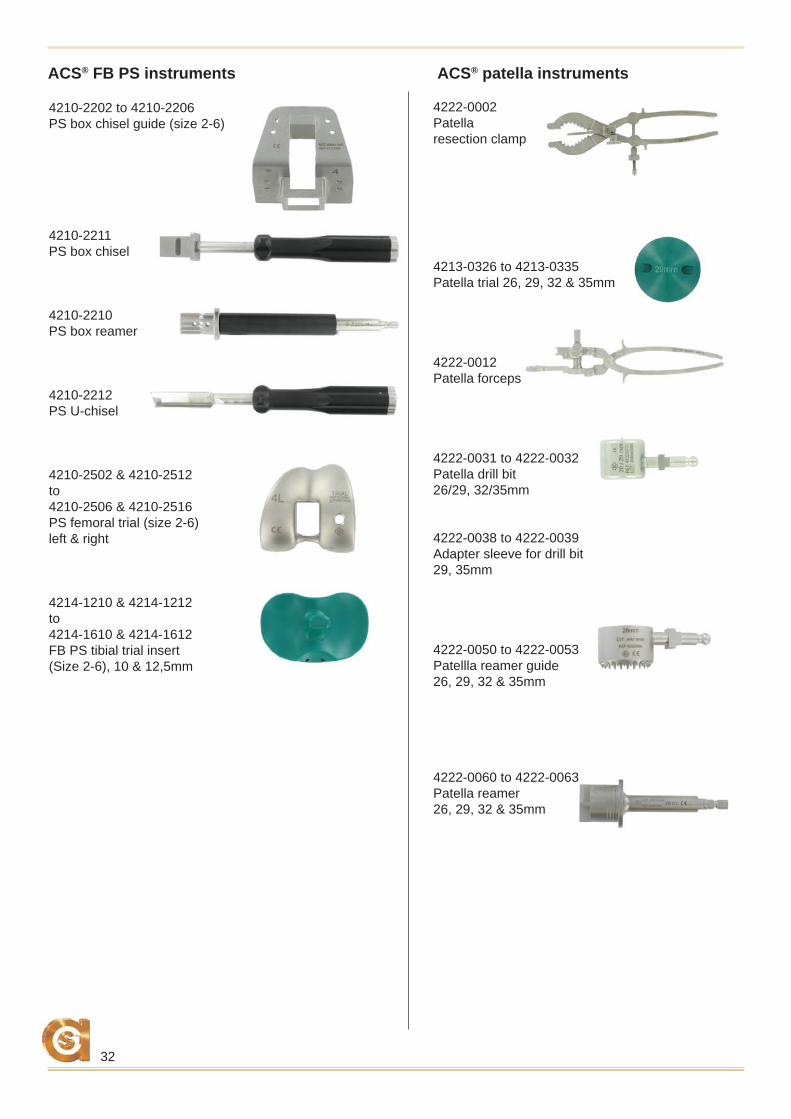
ACS® FB PS instruments ACS® patella instruments
4210-2202 to 4210-2206PS box chisel guide (size 2-6)
4210-2211PS box chisel
4210-2210PS box reamer
4210-2212PS U-chisel
4210-2502 & 4210-2512to4210-2506 & 4210-2516PS femoral trial (size 2-6)left & right
4214-1210 & 4214-1212to4214-1610 & 4214-1612FB PS tibial trial insert(Size 2-6), 10 & 12,5mm
4222-0002Patellaresection clamp
4213-0326 to 4213-0335Patella trial 26, 29, 32 & 35mm
4222-0012Patella forceps
4222-0031 to 4222-0032Patella drill bit26/29, 32/35mm
4222-0038 to 4222-0039Adapter sleeve for drill bit29, 35mm
4222-0050 to 4222-0053Patellla reamer guide26, 29, 32 & 35mm
4222-0060 to 4222-0063Patella reamer26, 29, 32 & 35mm


01230123000123
AC
SFB
OP
E-1
7120
9
*+E1
ICSC
AFBO
PE++
**+
$$E1
IC17
1209
++*implantcast GmbH
Lüneburger Schanze 26D-21614 Buxtehude
Germanyphone: +49 4161 744-0 fax: +49 4161 744-200
e-mail: [email protected]: www.implantcast.de
Your local distributor: