Embed Size (px)
Citation preview
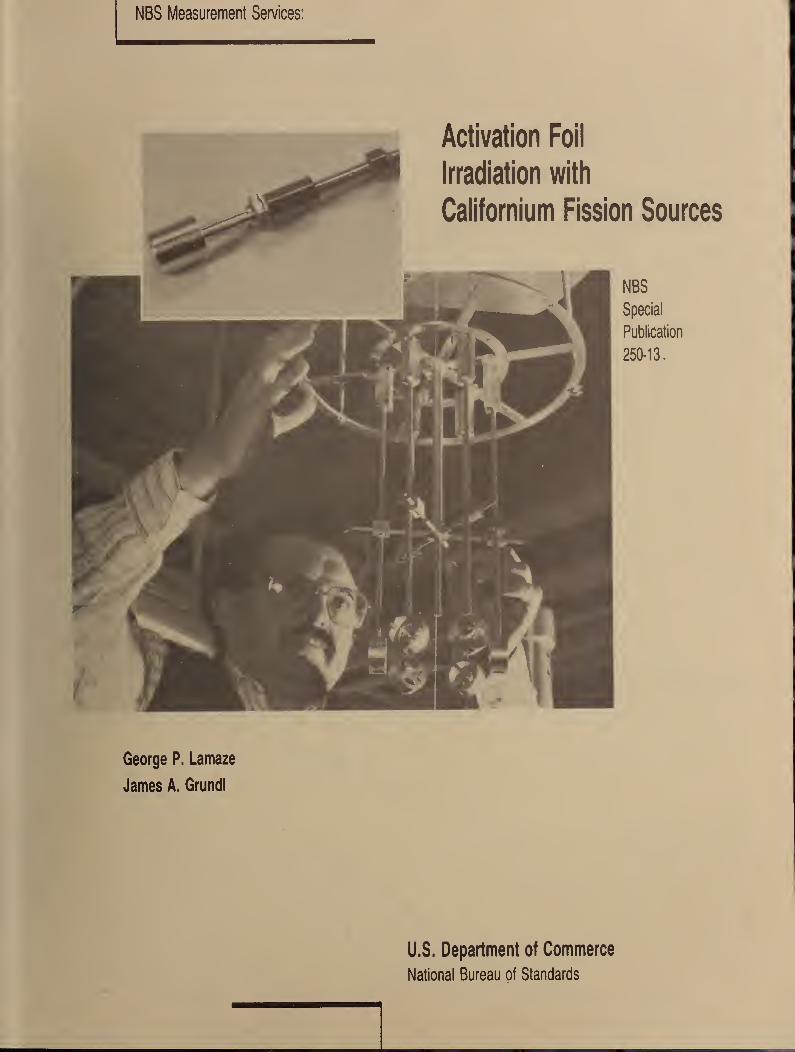
NBS Measurement Services:
Activation Foil
George P. Lamaze
James A. Grundl
U.S. Department of Commerce
National Bureau of Standards
Center for Radiation ResearchThe Center for Radiation Research is a major component of the National Measurement Laboratory in the NationalBureau of Standards. The Center provides the Nation with standards and measurement services for ionizingradiation and for ultraviolet, visible, and Infrared radiation; coordinates and furnishes essential supportto the National Measurement Support Systemfor ionizing radiation; conducts research in radiation relatedfields to develop improved radiation measurement methodology; and generates, conpiles, and criticallyevaluates data to meet major national needs. The Center consists of five Divisions and one Group.
Atomic and Plasma Radiation DivisionCarries out basic theoretical and experimental research into the • Atomic Spectroscopyspectroscopic and radiative properties of atoms and highly ionized • Atomic Radiation Dataspecies; develops well-defined atomic radiation sources as radiometric • Plasma Radiationor wavelength standards; develops new measurement techniques and
methods for spectral analysis and plasma properties; and collects,compiles, and critically evaluates spectroscopic data. The Divisionconsists of the following Groups:
Radiation Physics DivisionProvides the central national basis for the measurement of far ultra- • Far UV Physicsviolet, soft x-ray, and electron radiation; develops and disseminates • Electron Physicsradiation standards, measurement services, and data for for these radia- • Photon Physicstions; conducts theoretical and experimental research with electron,laser, ultraviolet, and soft x-ray radiation for measurement applica-tions; determines fundamental mechanisms of electron and photon inter-actions with matter; and develops advanced electron- and photon-basedmeasurement techiques. The Division consists of the following Groups:
Radiometric Physics Division
Provides national measurement standards and support services for ultra- • Spectral Radiometryviolet, visible, and infrared radiation; provides standards dissemination • Spectrophotometryand measurement quality assurance services; conducts research In optical • Radiometric Measurement Servicesradiation, pyrometry, photometry, and quantum radiometry; and developsspectroradiometric and spectrophotometric standards and calibrationprocedures. The Division consists of the following Groups:
Radiation Source and Instrumentation DivisionDevelops, operates, and improves major NBS radiation facilitiesincluding the electron Linac and race track microtron; develops,designs, and builds electronic and mechanical instrunentation forradiation programs and facilities; provides national leadershipin the standardization of nuclear instrunentation; and developsnew competence In radiation sources and Instrumentation. TheDivision consists of the following Groups:
• Accelerator Research• Linac Operations• Electronic Instrumentation• Mechanical Instrunentation
Ionizing Radiation Division
Provides primary national standards, measurement services, and basicdata for applications of ionizing radiation; develops new methods ofchemical and physical dosimetry; conducts theoretical and experimentalresearch on the fundamental physical and chemical interactions ofionizing radiation with matter; provides essential standards andmeasurement support services to the National Measurement SupportSystem for Ionizing Radiation; and develops and operates radiationsources needed to provide primary radiation standards, fields, andwell-characterized beams of radiation for research on radiationinteractions and for development of measurement methods. The Divisionconsists of the following Office and Groups:
Office of Radiation MeasurementRadiation TheoryRadiation Chemistry and Chemical
DosimetryNeutron Measurements and ResearchNeutron DosimetryRadioactivityX-Ray PhysicsDosimetry
Nuclear Physics GroupEngages in forefront research in nuclear and elementary particle physics;performs highly accurate measurements and theoretical analyses whichprobe the structure of nuclear matter; and Improves the quantitativeunderstanding of physical processes that underlie measurement science.
NBS MEASUREMENT SERVICES:ACTIVATION FOIL IRRADIATION WITHCALIFORNIUM FISSION SOURCES
George P. Lamaze
James A. Grundl
Center for Radiation Research
National Measurement Laboratoryj
National Bureau of Standards
Gaithersburg, MD 20899
I
U.S. DEPARTMENT OF COMMERCE, C. William Verity, Secretary
NATIONAL BUREAU OF STANDARDS, Ernest Ambler, Director
Issued March 1988
Library of Congress Catalog Card Number: 88-600508
National Bureau of Standards Special Publication 250-13
Natl. Bur. Stand. (U.S.), Spec. Publ. 250-13, 38 pages (Mar. 1988)
CODEN: XNBSAV
Commercial products— materials and instruments-are Identified in tfiis document for the sole pur-
pose of adequately describing experimental or test procedures. In no event does such identification
imply recommendation or endorsement by the National Bureau of Standards of a particular product;
nor does It imply that a named material or instrument is necessarily the best available for the purpose
it serves.
U.S. GOVERNMENT PRINTING OFFICEWASHINGTON: 1988
For sale by the Superintendent of Documents, U.S. Govemment Printing Office, Washington, DC 20402-9325
PREFACE
The calibration and related measurement services of the National Bureauof Standards are intended to assist the makers and users of precisionmeasuring instruments in achieving the highest possible levels ofaccuracy, quality, and productivity. NBS offers over 300 differentcalibration, special test, and measurement assurance services. Theseservices allow customers to directly link their measurement systems tomeasurement systems and standards maintained by NBS. These servicesare offered to the public and private organizations alike. They aredescribed in NBS Special Publication (SP) 250, NBS Calibration ServicesUsers Guide .
The Users Guide is being supplemented by a number of specialpublications (designated as the "SP 250 Series") that provide a
detailed description of the important features of specific NBScalibration services. These documents provide a description of the:
(1) specifications for the service; (2) design philosophy and theory;
(3) NBS measurement system; (4) NBS operational procedures; (5)assessment of measurement uncertainty including random and systematicerrors and an error budget; and (6) internal quality control proceduresused by NBS. These documents will present more detail than can begiven in an NBS calibration report, or than is generally allowed in
articles in scientific journals. In the past NBS has published suchinformation in a variety of ways. This series will help make this typeof information more readily available to the user.
This document (SP 250-13), NBS Measurements Services: Activation Foil
Irradiation with Californium Fission Sources, by G. P. Lamaze and J. A.
Grundl, is the thirteenth to be published in this new series of specialpublications. The scope of the service, the neutron fieldcharacteristics, the irradiation procedures, and the uncertainties in
the reported neutron fluences or fluence rates are described (see test
number 44080C in the SP 250 Users Guide). Inquiries concerning the
technical content of this document or the specifications for theseservices should be directed to the authors or one of the technical
contacts cited in SP 250.
The Center for Radiation Research (CRR) is in the process of publishing
21 documents in this SP 250 series, covering all of the calibrationservices offered by CRR. A complete listing of these documents can be
found inside the back cover.
NBS would welcome suggestions on how publications such as these might
be made more useful. Suggestions are also welcome concerning the need
for new calibration services, special tests, and measurement assuranceprograms
.
Joe D. SimmonsActing ChiefMeasurement Services
Chris E. KuyattDi rectorCenter for Radiation Research
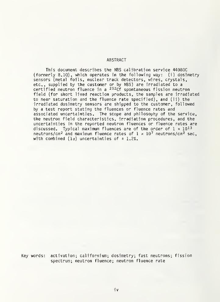
ABSTRACT
This document describes the NBS calibration service 440800(formerly 8.1Q), which operates in the following way: (i) dosimetrysensors (metal foils, nuclear track detectors, wires, crystals,etc., supplied by the customer or by NBS) are irradiated to a
certified neutron fluence in a 252Qf spontaneous fission neutronfield (for short lived reaction products, the samples are irradiatedto near saturation and the fluence rate specified), and (ii) theirradiated dosimetry sensors are shipped to the customer, followedby a test report stating the fluences or fluence rates andassociated uncertainties. The scope and philosophy of the service,the neutron field characteristics, irradiation procedures, and theuncertainties in the reported neutron fluences or fluence rates are
discussed. Typical maximum fluences are of the order of 1 x iQis
neutrons/cm2 and maximum fluence rates of 1 x 10^ neutrons/cm^ sec,
with combined (la) uncertainties of ± 1.2%.
Key words: activation; californium; dosimetry; fast neutrons; fission
spectrum; neutron fluence; neutron fluence rate
i V
TABLE OF CONTENTS
I. DESCRIPTION OF SERVICES AND FACILITIES 1
I. a. Generic Description 2
I.b. Available Fission Neutron Exposures 2
I.e. Corrections for Neutron Scattering at 5 cm Position 2
I. d. Configuration and Characteristics 2
II. NEUTRON FIELD CHARACTERIZATION 8
II. a. Neutron Fluence 9
II. b. Neutron Spectrum 10
Il.b.l. Measurement 10
II. b. 2. Evaluated Spectrum 10
III. DETAILED OPERATING PROCEDURES 12
IV. FLUENCE CALCULATION AND UNCERTAINTIES 13
IV. a. Fluence and Fluence Rate Calculations 13
IV. b. Uncertainties 14
V. BENCHMARK REFERENCING 15
VI. SAFETY 16
REFERENCES 17
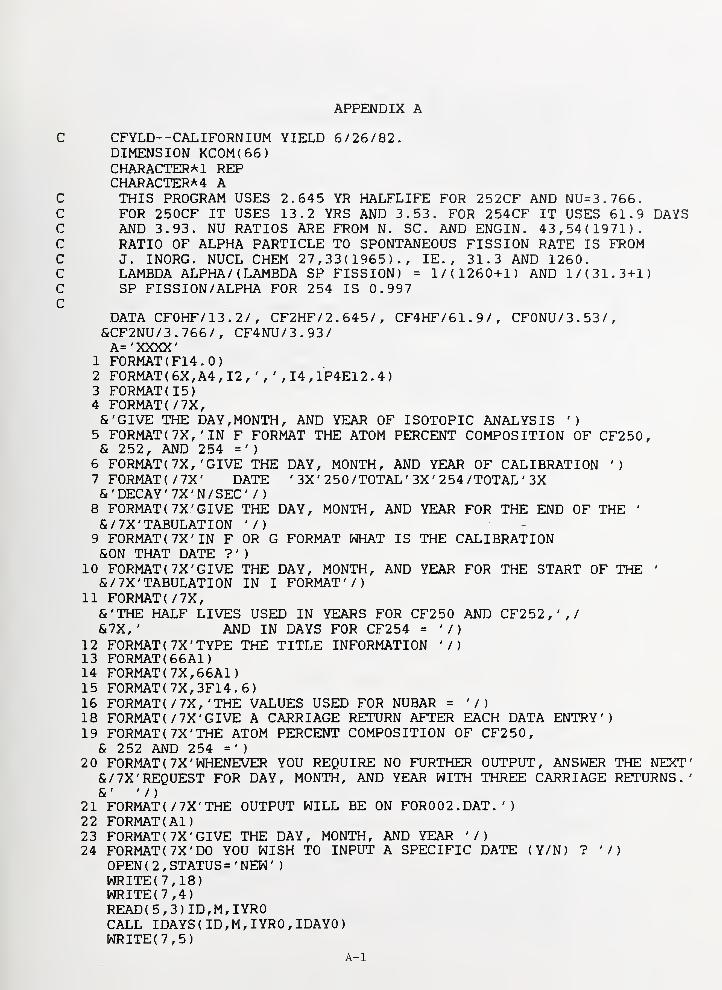
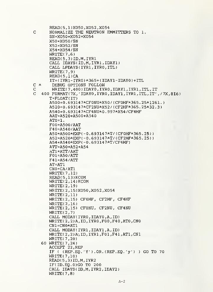
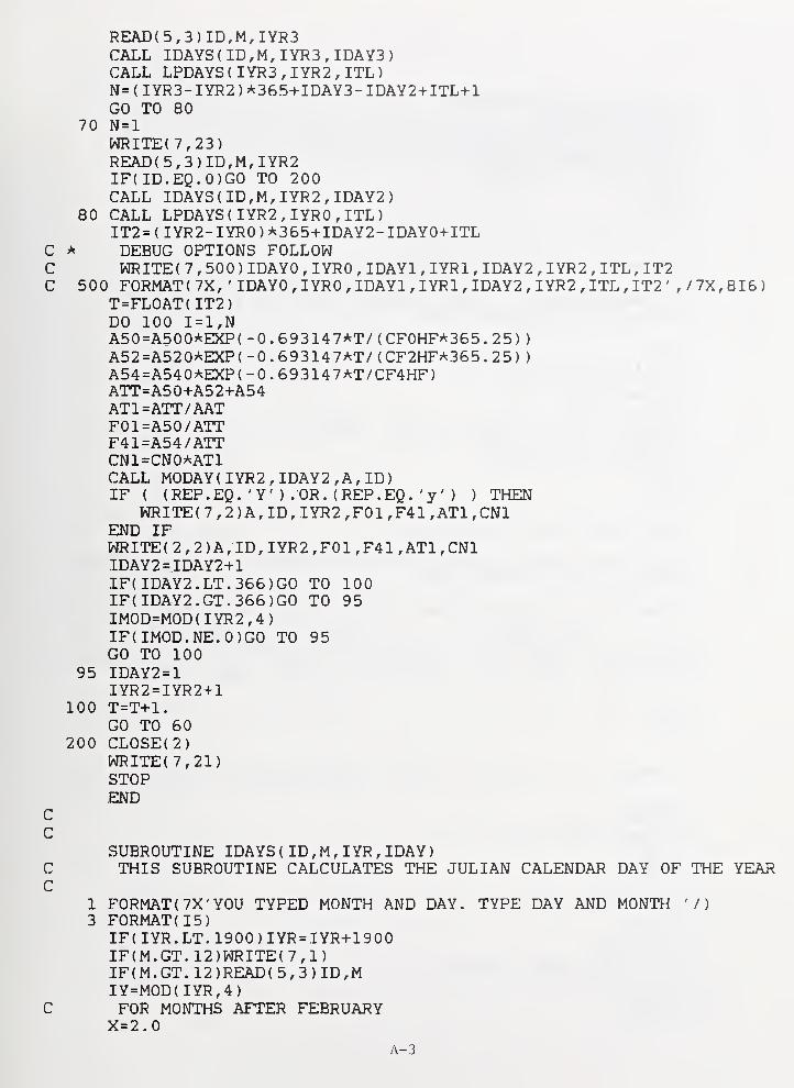
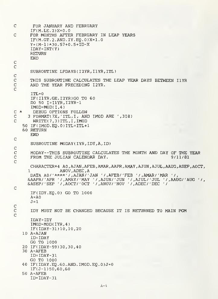
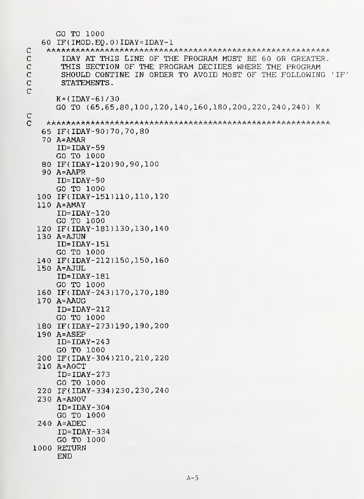
APPENDIX A. Listing of CFYLD A-1
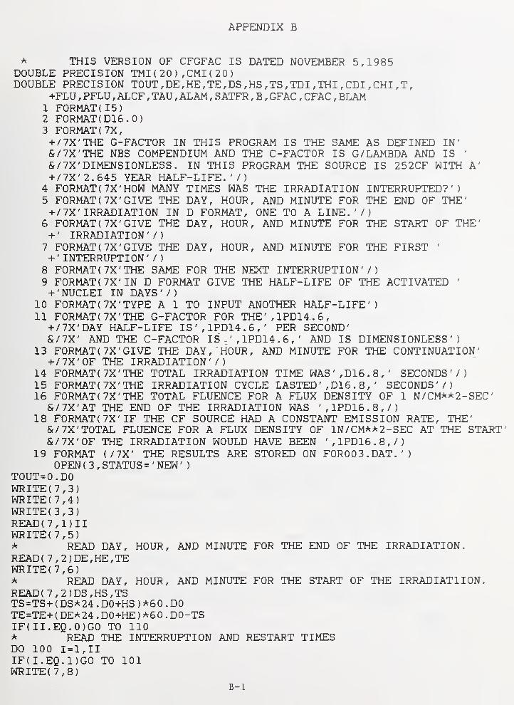
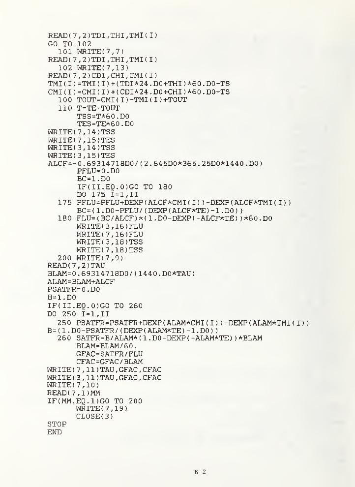
APPENDIX B. Listing of CFGFAC B-1
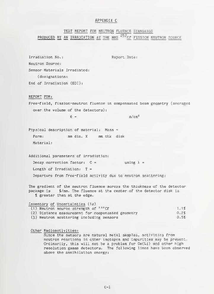
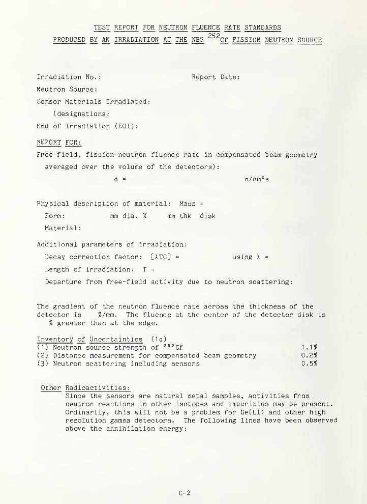
APPENDIX C. Sample Test Reports C-1
LIST OF TABLES
Page
TABLE 1. 252cf Fission Neutron Field Parameters and UncertaintyComponents 5
TABLE 2, Typical Neutron Fluence and Sensor Response Perturbationsdue to Neutron Scattering 8
TABLE 3. Evaluated Fission Neutron Spectra for 252cf 235u -jn
45-Group Format 11
TABLE 4. Uncertainty Estimates for 252cf ^pcl 235u Evaluated FissionNeutron Spectra 12
TABLE 5. Net Scattering Corrections for some Common Sensors 14
vi
LIST OF FIGURES
Page
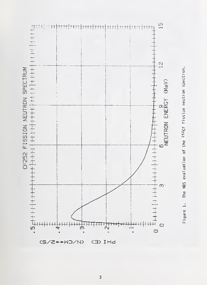
Fig. 1 The NBS evaluation of the 252Qf fission neutron spectrum 3
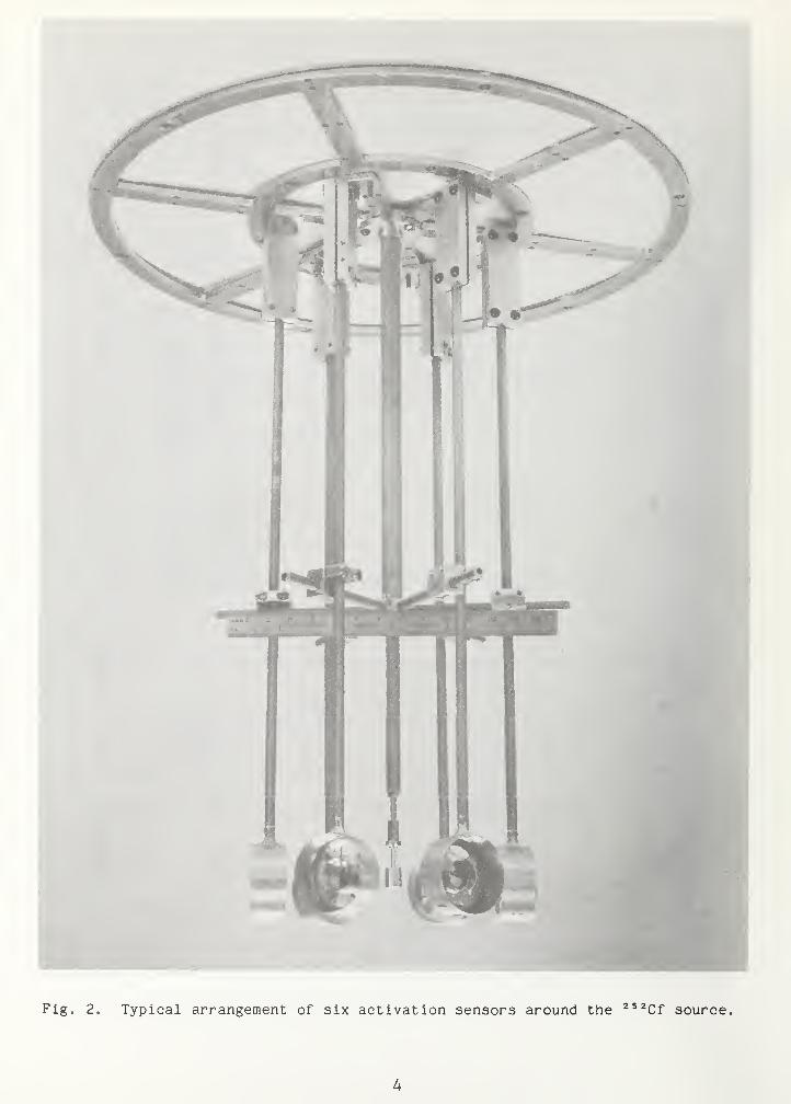
Fig. 2 Typical arrangement of six activation sensors around the
252cf source 4
Fig. 3 Scattering materials in the low-mass 252cf fission neutron
source capsule 6
vii
I. DESCRIPTION OF SERVICES AND FACILITIES
NBS maintains standard fission neutron fields to supply calibrationirradiations and certified fluence and fluence rate standards. The NBS 252cfFission Neutron Source (typical maximum fluence of 1.0 x 10^^ neutrons/cm^ in
24 hours) provides one such standard neutron field spectrum. Known fluencesand fluence rates are based upon Cf source strengths that are traceable to
NBS-I, the U.S. national fast-neutron source standard.
This calibration service (44080C) operates in the following way:
1) dosimetry sensors (metal foils, nuclear track detectors, wires, crystals,etc., supplied by the customer or by NBS) are irradiated to a certifiedneutron fluence in a 252Qf spontaneous fission neutron field (for short lived
reaction products, the samples are irradiated to near saturation and the
fluence rate specified), and 2) the irradiated dosimetry sensors are shippedto the customer, followed by a test report stating the fluences and associateduncertainties. For a typical activation sensor, the customer measures the
activity of the irradiated sensor with his own sensor system and corrects the
activity to obtain the activity at the end of the irradiation (EOI). This
activity is then corrected for scattering effects (see section 2.1) to obtain
the free-field activity at EOI. For simple decay, this free-field activity of
the neutron fluence standard in disintegrations per second is related to the
free-field neutron fluence by the activation equation:
A = A • C • N • a • $ (1)
where: A = free-field activity at EOI (Bq),
A = decay constant of the reaction product (s"i),
C = decay correction factor (dimensi onl ess) given in the test report
(this corrects for activity lost during the irradiation),
N = number of atoms of the target isotope,
a = fission-spectrum-averaged reaction cross section (cm^)
,
and $ = free-field fission neutron fluence (n/cm^) given in the test
report.
The commonly employed reaction rate probability (experimentally, the saturated
specific activity) is given by
ICTN =•
*
where: ttTKT = reaction rate probability (disintegrations per second per
nucl eus )
,
(j)= ($/T), the effective neutron fluence rate (n/cm^ s) or flux
density, and
T = the length of the irradiation given in the test report.
1
I. a. GENERIC DESCRIPTION
A standard 252(;f neutron field consists of neutrons from the spontaneousfission of 252Qf y^j^h little or no energy degradation. The median energy of
the spectrum is 1.68 MeV, with 98% of the neutrons between 0.1 MeV and 8 MeV
(see fig. 1). Neutron fluence rates in the range of 10'^ n/(cm2 s) are
obtained in isolated environments near small, intense ^^^Cf fission sources.Neutron fluences are established in terms of neutron source strength,irradiation time, and source-sensor distance; no microscopic nuclear data or
irradiation monitors are required. Certified free-field fluences of up to10^3 n/cm2 may be obtained with uncertainties as low as ± 1.2% (la).
Measurements of the 252Qf fission neutron spectrum and the closelyrelated the ^ssy fission neutron spectrum are extensive and wel 1 -documented[1]. These two standard neutron fields are therefore much better known thanany other benchmark employed for reactor dosimetry calibration. Moreover, in
the energy range above 2 MeV, many neutron fields in and around test and powerreactors have fission-spectrum-like components.
I.b. AVAILABLE FISSION NEUTRON EXPOSURES
e fluence rate (5 cm from source) ~ 2 x 10'^ n/(cm2 s)
© nominal maximum fluence 1 x lO^^ n/cm2
9 accuracy of free-field fluence (la) ± 1.2%
I.e. CORRECTIONS FOR NEUTRON SCATTERING AT 5 CM POSITION
o Net perturbation for threshold sensor reaction rates: < (1.0 ± 0.8)%(la)
• Net perturbation for ^ssy (n,f) sensor reaction rate: (1.2 ± 0.4)%(la)
I.d. CONFIGURATION AND CHARACTERISTICS [2,3]
The two irradiation locations at NBS are distinguished by the degree towhich the neutron source is isolated from environmental neutron return:
Location A: Large room with thick walls and open ceiling. Source 2.2
meters above floor, nearest wall 4.1 meters.
Location B: Corner area of room with thin walls and ceiling. Source 2.8meters above floor, nearest wall 4.3 meters.
At both locations a lightweight source-sensor assembly is available forirradiation of passive and active neutron sensors. The source-sensor assemblywith six activation sensors mounted on three axes is shown in figure 2.
Location A is currently being used for calibration of health physics typedosimeters. All activation foil irradiations are now done at location B. All
further site specific properties discussed in this report will apply to
location B only, although the site specific properties are very similar.
2
CS/2->«-*tN3/N> C3> IHd
3
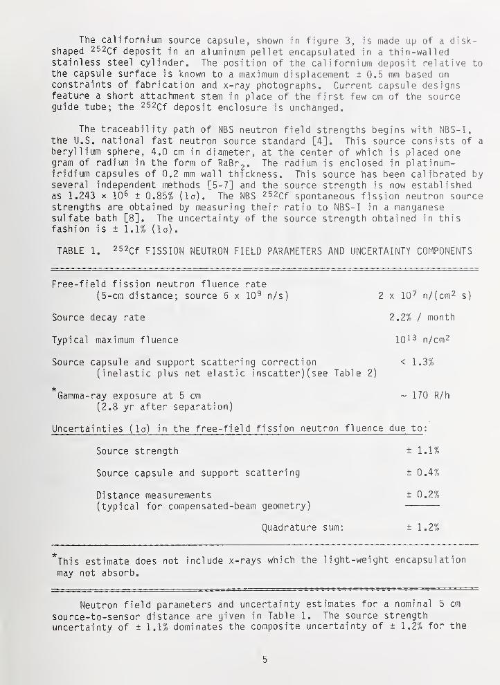
The californium source capsule, shown in fiyure 3, is made up of a disk-shaped 252Qf deposit in an aluminum pellet encapsulated in a thin-walledstainless steel cylinder. The position of the californium deposit relative tothe capsule surface is known to a maximum displacement ± 0.5 mm based onconstraints of fabrication and x-ray photographs. Current capsule designsfeature a short attachment stem in place of the first few cm of the sourceguide tube; the 252cf deposit enclosure is unchanged.
The traceability path of NBS neutron field strengths begins with NBS-I,the U.S. national fast neutron source standard [4]. This source consists of a
beryllium sphere, 4.0 cm in diameter, at the center of which is placed onegram of radium in the form of RaBr^. The radium is enclosed in platinun-iridium capsules of 0.2 mm wall thickness. This source has been calibrated byseveral independent methods [5-7] and the source strength is now establishedas 1.243 X 10^ ± 0.85% (la). The NBS 252cf spontaneous fission neutron sourcestrengths are obtained by measuring their ratio to NBS-I in a manganesesulfate bath [8]. The uncertainty of the source strength obtained in thisfashion is ± 1.1% (la)
.
TABLE 1. 252cf FISSION NEUTRON FIELD PARAMETERS AND UNCERTAINTY COMPONENTS
Free-field fission neutron fluence rate
(5-cm distance; source 6 x 10^ n/s) 2 x 10^ n/(cm2 s]
Source decay rate 2.2% / month
Typical maximum fluence lO^^ n/cm^
Source capsule and support scattering correction < 1.3%(inelastic plus net elastic inscatter) (see Table 2)
it
Gamma-ray exposure at 5 cm ~ 170 R/h
(2.8 yr after separation)
Uncertainties (la) in the free-field fission neutron fluence due to :
Source strength ± 1.1%
Source capsule and support scattering ± 0.4%
Distance measurements ± 0.2%(typical for compensated-beam geometry)
Quadrature sum: ± 1.2%
*This estimate does not include x-rays which the light-weight encapsulation
may not absorb.
Neutron field parameters and uncertainty estimates for a nominal 5 cm
source-to-sensor distance are given in Table 1. The source strength
uncertainty of ± 1.1% dominates the composite uncertainty of ± 1.2% for the
5
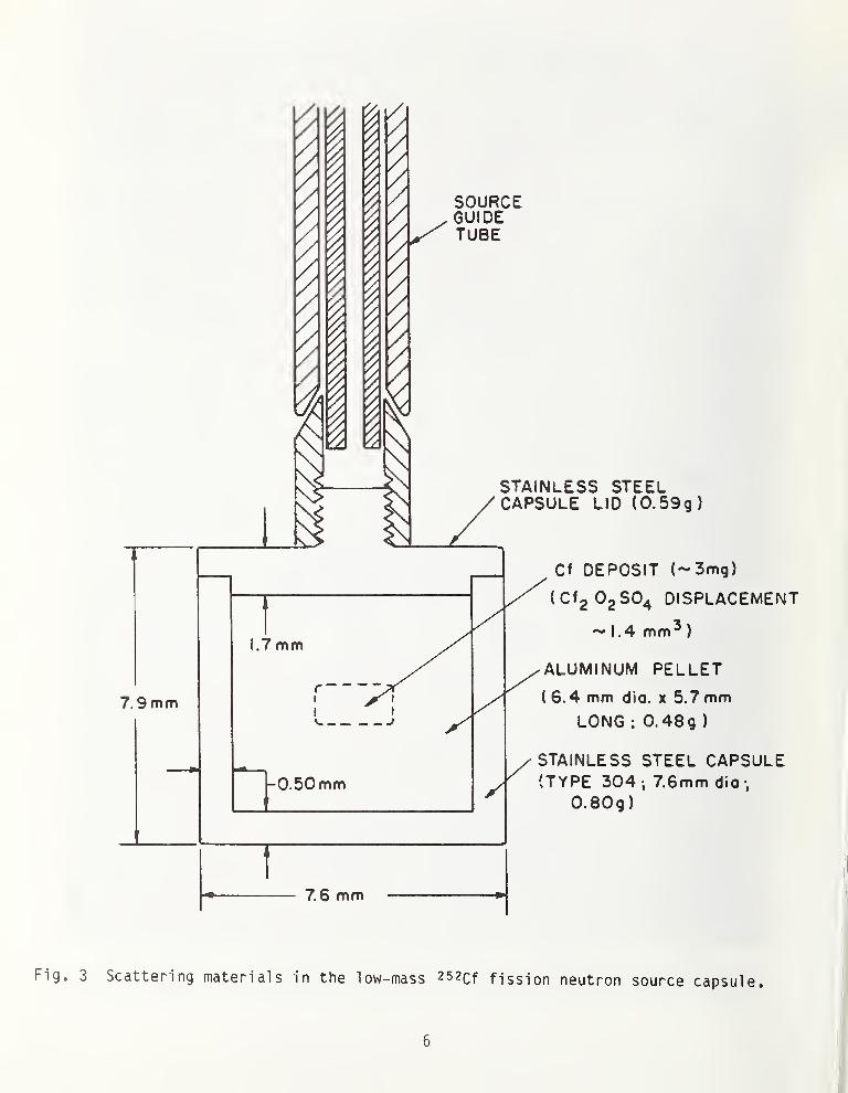
7.9mm
1.7 mm
-0.50mm
7.6 mm
SOURCEGUIDETUBE
STAINLESS STEELCAPSULE LID (0.59g)
Cf DEPOSIT (-3mg)
OgSO^ DISI
1.4 mm^
)
(CfgOgSO^ DISPLACEMENT
ALUMINUM PELLET
( 6.4 mm dio. x 5.7 mmLONG : 0.48g )
STAINLESS STEEL CAPSULE(TYPE 304 i 76mm dio -,
0.80g)
Fig. 3 Scattering materials in the low-mass 252cf fission neutron source capsule.
free-field fission neutron fluence. The irradiation geometry shown infigure 2 is termed compensated-beam geometry and refers to the experimentalpractice of placing sensors of similar sensitivity in pairs on opposite sidesof the source, and nearly equidistant from it. The geometric mean of theresponses of the two sensors in this case can be expressed in terms of a meanneutron fluence which is a function of sensor separation with very littledependence on source position.
It can be shown that the percent uncertainty due to source displacementon axis with the sensors is (Ar2/r2-Ar2) x lOO.
For a 0.5-mm displacement where r = 50 mm, the uncertainty is 0.01'/,. Fordisplacement perpendicular to the displacement axis, the maximum percent
decrease in the fluence rate is (2»[/r^+Ax-r]/r) x 100. For a perpendiculardisplacement of 0.5 mm where r = 50 mm, the fluence rate is decreased by 0.1%.The uncertainty in source position therefore does not contribute to the over-all uncertainty. The principal percent uncertainty due to positioning can be
shown to be equal to (2Ad/d) x 100 where d is the measured distance betweensamples and Ad is the uncertainty in measurement. For the Boice C786coordinate measurement machine, the measuremnt accuracy for linear distancesis ± .005 mm (la). For our sample holders, which are not perfectly rigid, thereproducibility of measurements is ± .04 mm (la). For the previouslydiscussed case of a sample 50 mm from the source (100 mm sample separation),the uncertainty from positioning uncertainty is ± .08% (la).
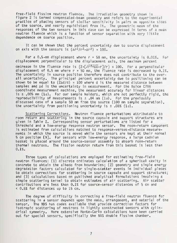
Scattering Corrections . Neutron fluence perturbations attributable toroom return and scattering in the source capsule and support structures are
given in Table 2. Corresponding sensor perturbations are listed for a
threshold and a low-energy response neutron sensor. The room-return componentis estimated from calculations matched to response-versus-di stance measure-ments in which the source is moved while the sensors are kept at their normal
5 cm position [9]. For sensors with low-energy response, a large cadmiumbasket is placed around the source-sensor assembly to absorb room-returnthermal neutrons. The fission neutron return from this basket is less than
0.1%.
Three types of calculations are employed for estimating free-fieldneutron fluences: (1) discrete ordinates calculation of a spherical cavity in
concrete to obtain the albedo from boundaries; (2) geometry and simple energydegradation factors calculated for single-scatter events in individual pieces
to obtain corrections for scattering in source capsule and support structures;and (3) calculations based on published analytical formulations involving a
simple scattering kernel to obtain estimates of air scattering. Air scattercontributions are less than 0.1% for source-sensor distances of 5 cm and
< 0.5% for distances up to 15 cm.
The degree of difficulty in correcting a free-field neutron fluence for
scattering in a sensor depends upon the mass, arrangement, and material of the
sensor. The NBS has codes available that provide correction factors for
isotropic scattering of neutrons in lightly constructed sensors with cylin-drical symmetry. More extensive Monte-Carlo calculations have been carriedout for special sensors, specifically the NBS double fission chamber.
7
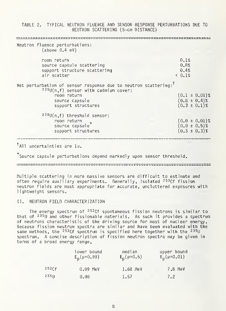
TABLE 2. TYPICAL NEUTRON FLUENCE AND SENSOR RESPONSE PERTURBATIONS DUE TONEUTRON SCATTERING (5-cm DISTANCE)
Neutron fluence perturbations:(above 0.4 eV)
room return 0.1%source capsule scattering 0.8%support structure scattering 0.4%air scatter < 0.1%
Net perturbation of sensor response due to neutron scattering:^235u(n,f) sensor with cadmium cover:
room return (0.1 ± 0.01)%source capsule (0.8 ± 0.4)%support structures (0.3 ± 0.1)%
238u(n,f) threshold sensor:
room return ^ (0.0 ± 0.01)%source capsule (0.0 ± 0.5)%support structures (0.3 ± 0.3)%
^All uncertainties are la.
Source capsule perturbations depend markedly upon sensor threshold.
Multiple scattering in more massive sensors are difficult to estimate andoften require auxiliary experiments. Generally, isolated 252cf fissionneutron fields are most appropriate for accurate, uncluttered exposures withlightweight sensors.
II. NEUTRON FIELD CHARACTERIZATION
The energy spectrum of 252Qf spontaneous fission neutrons is similar tothat of 235u other fissionable materials. As such it provides a spectrumof neutrons characteristic of the driving source for most of nuclear energy.Because fission neutron spectra are similar and have been evaluated with thesame methods, the 252Qf spectrum is specified here together with the ^ssy
spectrum. A concise description of fission neutron spectra may be given in
terms of a broad energy range,
lower bound median upper bound
Ep(p=0.99) Ep(p=0.5) Ep(p=0.01)
252cf 0.09 MeV 1.68 MeV 7.8 MeV
235U 0.08 1.57 7.2
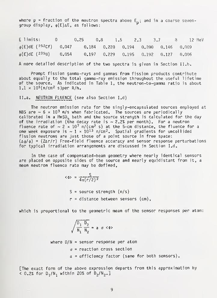
where p = fraction of the neutron spectra above E ; and in a coarse seven-group display, (|)(E)aE, as follows: ^
E limits: 0 0.25 0.8 1.5 2.3 3.7 8 12 fleV
(|)(E)dE ( 252cf) 0.047 0.184 0.220 0.194 0.200 0.146 0.009
(|)(E)dE (235U) 0.054 0.197 0.229 0.195 0.192 0.127 0.006
A more detailed description of the two spectra is given in Section II. b.
Prompt fission gamma-rays and gammas from fission products contributeabout equally to the total gamma-ray emission throughout the useful lifetimeof the source. As indicated in Table 1, the neutron-to-gamma ratio is about1.1 X 105(n/cm2 s)per R/h.
II. a. NEUTRON FLUENCE (see also Section I.d)
The neutron emission rate for the singly-encapsulated sources employed at
NBS are ~ 6 x 10^ n/s when fabricated. The sources are periodicallycalibrated in a flnSOi^ bath and the source strength is calculated for the day
of the irradiation (the decay rate is ~ 2.2% per month). For a neutronfluence rate of ~ 2 x lO'' n/{cm^ s) at the 5-cm distance, the fluence for a
one week exposure is ~ 1 x lO^^ n/cm^. Spatial gradients for uncoil ided
fission neutrons are just those of a point source in free space:
(A(j)/<j)) = (2Ar/r) Free-field fluence accuracy and sensor response perturbationsfor typical irradiation arrangements are discussed in Section I.d.
In the case of compensated-beam geometry where nearly identical sensorsare placed on opposite sides of the source and nearly equidistant from it, a
mean neutron fluence rate may be defined.
<$> =4TT(r/2)2
S = source strength (n/s)
r = distance between sensors (cm),
which is proportional to the geometric mean of the sensor responses per atom;
« a a <$>
where D/N = sensor response per atom
a = reaction cross section
a = efficiency factor (same for both sensors).
[The exact form of the above expression departs from this approximation by
< 0.2% for D^/Nj within 20% of D2/N2.]
9
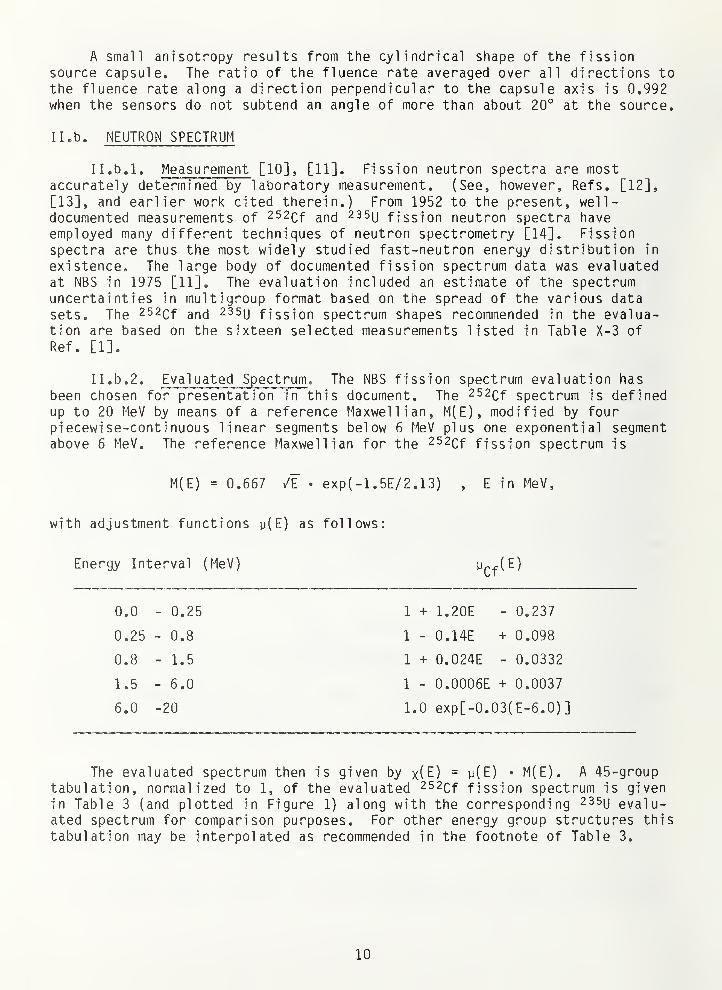
A small anisotropy results from the cylindrical shape of the fissionsource capsule. The ratio of the fluence rate averaged over all directions tothe fluence rate along a direction perpendicular to the capsule axis is 0.992when the sensors do not subtend an angle of more than about 20° at the source.
II. b. NEUTRON SPECTRUM
Il.b.l. Measurement [10], [11]. Fission neutron spectra are mostaccurately determined by laboratory measurement. (See, however, Refs. [12],
[13], and earlier work cited therein.) From 1952 to the present, well-documented measurements of 252cf 235u fission neutron spectra haveemployed many different techniques of neutron spectrometry [14]. Fissionspectra are thus the most widely studied fast-neutron energy distribution in
existence. The large body of documented fission spectrum data was evaluatedat NBS in 1975 [11]. The evaluation included an estimate of the spectrumuncertainties in multigroup format based on the spread of the various datasets. The 252Qf ^^d ^asy fission spectrum shapes recommended in the evalua-tion are based on the sixteen selected measurements listed in Table X-3 of
Ref. [1].
II. b. 2. Evaluated Spectrum . The NBS fission spectrum evaluation has
been chosen for presentation in this document. The 252cf spectrum is definedup to 20 MeV by means of a reference Maxwellian, M(E), modified by fourpiecewi se-conti nuous linear segments below 6 MeV plus one exponential segmentabove 6 MeV, The reference Maxwellian for the 252cf fission spectrum is
M(E) = 0.667 /F . exp(-1.5E/2.13) , E in MeV,
with adjustment functions y(E) as follows:
Energy Interval (MeV) ypf(E)
0.0 - 0.25 1 + 1.20E - 0.237
0.25 - 0.8 1 - 0.14E + 0.098
0.8 - 1.5 1 + 0.024E - 0.0332
1.5 - 6.0 1 - 0.0006E + 0.0037
6.0 -20 1.0 exp[-0.03(E-6.0)]
The evaluated spectrum then is given by x(E) = y(E) • M(E). A 45-grouptabulation, normalized to 1, of the evaluated 252cf fission spectrum is givenin Table 3 (and plotted in Figure 1) along with the corresponding ^ssy evalu-ated spectrum for comparison purposes. For other energy group structures this
tabulation may be interpolated as recommended in the footnote of Table 3.
10
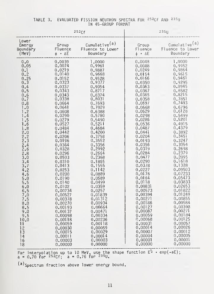
TABLE 3. EVALUATED FISSION NEUTRON SPECTRA FOR 252cf AND 235uIN 45-6R0UP FORMAT
252cf 2 35U
LowerEnergy
Boundary(MeV)
GroupFl uence({) • aE
Cumul at! ve^^)Fluence to Lower
Boundary
GroupFl uence4) • aE
Cumul at ! ve^^^Fluence to Lower
Bounda ry
0,0 0.0039 1 0000 0.0048 1 .00000.05 0.0074 0.9961 0.0088 0.99520.1 0.0?1 9 0.9887 0.0249 0.98640.2 0.0140 0.9668 0.01 54 0.961 5
0 ?5 0.01 52 0 9528 0.01 66 0.94610.3 0.0323 0.9377 0.0350 0.92950.4 0.0337 0.9054 0.0363 0.89450.5 0.0343 0.871
7
0.0367 0.85820 6 0 0343 0.8374 0.0365 0.821 5
0.7 0.0338 0.8031 0.0358 0.78510.8 0.0664 0.7693 0.0697 0.74931 .0 0.0641 0.7029 0.0668 0.67961 .2 0.0608 0.6388 0.0629 0.61281 .4 0.0290 0.5780 0.0298 0.54991 .5 0.0279 0.5490 0.0286 0.5201
1 .6 0.0527 0.521
1
0.0536 0.491
5
1 .8 0.0484 0.4684 0.0487 0.43792.0 0.0442 0.4200 0.0441 0.38922.2 0.0206 0.3758 0.0204 0.34512.3 0.01 96 0.3552 0.01 93 0.32472.4 0.0364 0.3356 0.0356 0.30542.6 0.0328 0.2992 0.0319 0.26982.8 0.0296 0.2664 0.0284 0.23793.0 0.0503 0.2368 0.0477 0.20953 4 0 0310 0.1865 0.0290 0.16183.7 0.041
3
0.1 555 0.0378 0.1 3284 2 0 0253 0.1 1 42 0.0227 0.095034 6 0 0200 0.0889 0.01 76 0.072335 n n 01 90 0 0689 0.01 64 0.054735 5 0.01 40 0.0499 0.01 18 0.03833
0*01 0? 0 0359 0.00831 0.026536 5 0 00734 0.0257 0.00573 0.018227 n/ . u 0 00527 0 01839 0.00394 0.01 2497 5 0 00378 0 01 31 2 0.00271 0.008558 no . u 0 nn?70 0 00934 0 00186 0.005848.5 0.00193 0.00664 0.00127 0.003989.0 0.001 37 0.00471 0.00087 0.002719.5 0.00098 0.00334 0.00059 0.00184
10.0 0.00118 0.00236 0.00068 0.0012511 0.00059 0.00118 0.00031 0.0005712 0.00030 0.00059 0.00014 0.0002613 0.00015 0.00029 0.00007 0.0001 2
14 0.00011 0.00014 0.00004 0.0000516 0.00003 0.00003 0.00001 0.00001
18 0.00000 0.00000 0.00000 0.00000
For interpolation up toa = 0.70 for 252cf; a =
10 MeV, use the shape0.76 for 235U.
function E'^ . exp(-aE);
^^^Spectrum fraction above lower energy bound
11
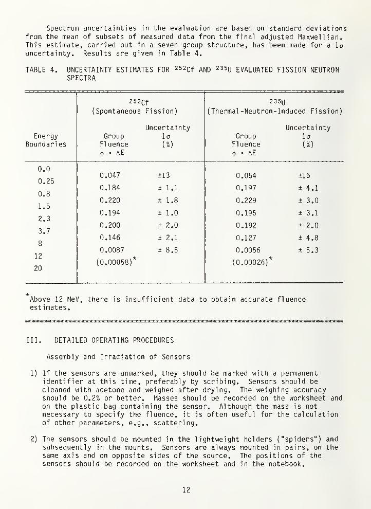
Spectrum uncertainties in the evaluation are based on standard deviationsfrom the mean of subsets of measured data from the final adjusted Maxwellian,This estimate, carried out in a seven group structure, has been made for a launcertainty. Results are given in Table 4.
TABLE 4. UNCERTAINTY ESTIMATES FOR 252cf AND 235u EVALUATED FISSION NEUTRONSPECTRA
EnergyBoundari es
252cf(Spontaneous Fission)
Uncertai nty
235U
(Thermal -Neutron -Induced Fi ssion)
Uncertai nty
d I u u 1 n fir ni 1 n 1 a
Fl uence (%) Fl uence (%)
(}) • AE (j) • AE
0.047 ±13 0.054 ±16
0.184 ± 1.1 0.197 ± 4.1
0.220 ± 1.8 0.229 ± 3.0
0.194 ± 1.0 0.195 ± 3.1
0.200 ± 2.0 0.192 ± 2.0
0.146 ± 2.1 0.127 ± 4.8
0.0087 ± 8.5 0.0056 ± 5.3
(0.00058)* (0.00026)*
0.0
0.25
0.8
1.5
2.3
3.7
8
12
20
Above 12 MeV, there is insufficient data to obtain accurate fluenceestimates.
III. DETAILED OPERATING PROCEDURES
Assembly and Irradiation of Sensors
1) If the sensors are unmarked, they should be marked with a permanentidentifier at this time, preferably by scribing. Sensors should be
cleaned with acetone and weighed after drying. The weighing accuracyshould be 0.2% or better. Masses should be recorded on the worksheet and
on the plastic bag containing the sensor. Although the mass is not
necessary to specify the fluence, it is often useful for the calculationof other parameters, e.g., scattering.
2) The sensors should be mounted in the lightweight holders ("spiders") andsubsequently in the mounts. Sensors are always mounted in pairs, on thesame axis and on opposite sides of the source. The positions of thesensors should be recorded on the worksheet and in the notebook.
12
3) Have the shops measure the separation distance of the sensor pairs on thecoordinate measuring machine. This should be a direct measurement of
face-to-face separation when possible. Record all parameters, so that a
final center-to-center separation can be obtained. A notebook sketch ofthe measurement procedure is advisable. The current shop contact is
Gene Morgan at extension 2448.
4) Arrange time at the Time-of -Fl i ght-Faci 1 i ty (TOFF) with Linac Operations,CW Operations, and the Neutron T-O-F group. Notify Health Physics.
5) Mount the source and sensor holder ring at the TOFF and connect thedesired source to the beaded chain. For some irradiations, the cadmiumshield will be necessary and should be mounted at this time. Lock theroad gate with padlock and put up any required ropes and signs (require-ments vary with source strength and length of irradiation). Be sure thatthere are no persons at the TOFF end stations or in the blockhouse. Turnon the red outside warning lights.
6) Check time marking instrument with telephone time (844-2525) or Naval
Observatory Time (653-0258). Raise the source while noting the time.Note that the source up warning light has come on. After securing thesource, record the time in notebook and source activities log. Visuallyinspect the source with telescope when possible.
7) On leaving, close and padlock locking gate 11; put up rope and sign in
hallway; close but do not lock door at top of stairwell; make sure that Cf
source up sign is showing; leave sign with your name and phone numbersshowing; leave appropriate signs on external door and in Linac controlroom.
8) At the end of the irradiation (EOI) ,again check time. Lower the source
while noting the time. Be sure that the source up warning light goes out !
Record the EOI time in notebook and source activities log. Later be surethat these times are recorded on the worksheets. Secure source, unlockroad gate, remove appropriate ropes and signs. Remove sensor holder.
9) Remove sensors from holders and package individually in labeled plasticcontainers. Store in shielded card file in Building 235, Room B123.
IV. FLUENCE CALCULATIONS AND UNCERTAINTIES
IV. a. FLUENCE AND FLUENCE RATE CALCULATIONS
1) Obtain the source strength, S, from output of the FORTRAN program CFYLD(See Appendix A). This program can be run for a specific day or can list
in tabular form the source strength for consecutive days. The sourcestrength of the most recent manganous sulfate bath measurements of the
source is entered and the program uses the 252cf hg-jf ]]fQ to calculatethe source strength on the days of interest.
13
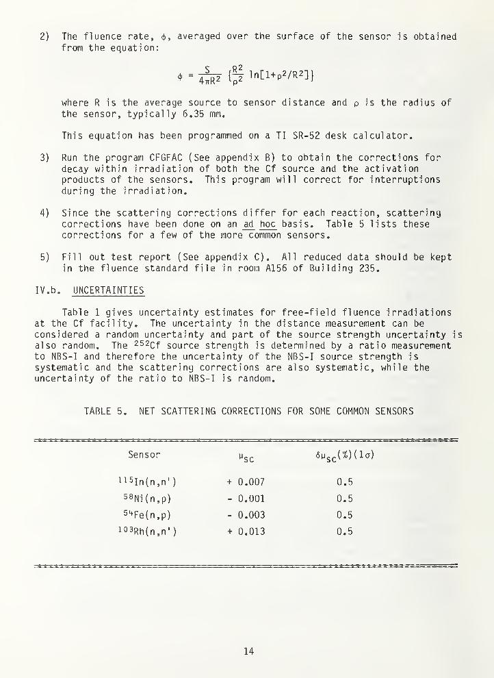
2) The fluence rate, (j), averaged over the surface of the sensor is obtainedfrom the equation:
where R is the average source to sensor distance and p is the radius of
the sensor, typically 6.35 mm.
This equation has been programmed on a TI SR-52 desk calculator,
3) Run the program CFGFAC (See appendix B) to obtain the corrections fordecay within irradiation of both the Cf source and the activationproducts of the sensors. This program will correct for interruptionsduring the irradiation.
4) Since the scattering corrections differ for each reaction, scatteringcorrections have been done on an ad hoc basis. Table 5 lists thesecorrections for a few of the more common sensors.
5) Fill out test report (See appendix C). All reduced data should be keptin the fluence standard file in room A156 of Building 235.
IV. b. UNCERTAINTIES
Table 1 gives uncertainty estimates for free-field fluence irradiationsat the Cf facility. The uncertainty in the distance measurement can be
considered a random uncertainty and part of the source strength uncertainty is
also random. The ^^^Cf source strength is determined by a ratio measurementto NBS-I and therefore the uncertainty of the NBS-I source strength is
systematic and the scattering corrections are also systematic, while theuncertainty of the ratio to NBS-I is random.
TABLE 5. NET SCATTERING CORRECTIONS FOR SOME COMMON SENSORS
Sensor ^c
ii5in(n,n') + 0.007 0.5
58Ni(n,p) - 0.001 0.5
5'^Fe(n,p) - 0.003 0.5
i03Rh(n,n'
)
+ 0.013 0.5
14
V. BENCHMARK REFERENCING
A benchmark neutron field is a wel 1 -character i zed neutron field whichwill provide an accurate neutron fluence for validation or calibration of
experimental techniques and methods. For purposes of fluence transfer to a
study field, the benchmark field should have a neutron energy spectrum that is
similar to the dosimetry environment to be monitored. Exposing identicalsensors in both the benchmark field and the study field and hence determiningreaction rate ratios, eliminates a number of systematic errors (detectorefficiency, gamma attenuation, absolute cross section values, etc.) in thedetermination of the unknown fluence.
Exposure of a dosimetry sensor to a known neutron fluence, xcf» ''^ ^
252cf fission spectrum establishes a calibration factor,
Q _ [observed sensor response]
IxQf neutron fluence] '
which may be used in conjunction with the cal cul ated fission-spectrum-averagedcross section, a^, for the sensor reaction to obtain a consistent benchmark
calibration. The cross section, a , should be calculated with (1) the fissionspectrum shape associated with the ^a priori spectrum (e.g., the source spec-
trum if the a priori spectrum is from a neutron transport calculation); and
(2) the same energy dependent reaction cross section, R(E), used to calculatethe spectrum averaged cross sections of the study field.
[If the absolute detection efficiency for the dosimetry measurementmethod has been established (e.g., a good resolution fission chamber with
known deposit mass, or a calibrated gamma counting system and known reactionparameters, branching ratios, isotopic abundances, fission yields etc.), then
the "observed sensor response" in Eq. (1) becomes the reaction probability,and G is an observed spectrum-averaged cross section for the fissionspectrum.] The calibration factor may then be applied to the investigation of
a study spectrum.
By irradiating samples identical to those irradiated in the 252cf fjeld,
the fluence of the study field, ^'g^jj^y. can be obtained as a simple ratio of
sensor responses, D, and spectrum averaged cross sections, a, so that:
(2)*^studv _ ^studv ^studv
D a $X XX
In practice, [D^^^^y^D ) is simply the time history corrected counting
rate ratio of the sample irradiated in the unknown field to that irradiated in
the Cf field. Uncertainties due to isotopic abundances, nuclear parameters,detector efficiencies, etc., disappear. The cross section ratios must be
calculated, but the absolute value becomes unimportant. The value of is
that given in the test report and one then solves equation (2) for^s^udy*
15
VI. SAFETY
The neutron sources used for these irradiation services range in sourcestrength from 1 to 5 x 10^ n/s. While these sources are not lethal,mishandling can result in radiation exposures well over the legal limit forradiation exposures. The sources should be handled remotely. If closehandling is necessary (e.g., when remounting the source on its holder), thesource should be placed in the water tank. New irradiation setups should be
first practiced with the dummy sources expressly designed for this purpose.Personnel dosimeters must be worn at all times and a "chirper" is recommendedwhen close handling is necessary. Unattended irradiations require that thearea be locked to prevent accidental entry. Ropes with warning signs shouldbe placed at the 2.5 mR radiation level in accordance with NRC regulations.Health Physics will assist in determining the rope locations if necessary.
The irradiated samples will be radioactive, but at a very low level
(usually a few nanocuries). There is therefore no hazard from the samples,but all radioactive shipping regulations must still be followed.
16
REFERENCES
[1] Grundl , J., and Eisenhauer, C, "Compendium of Benchmark Neutron Fields forReactor Dosimetry," NBSIR 85-3151 (January, 1986).
[2] Grundl, J. A., Spiegel, V., Eisenhauer, C. M. , Heaton II, H. T.
,
Gilliam, D. M. NBS; and Bigelow, J., ORNL; "A Cal i f orni um-252 FissionSpectrum Irradiation Facility for Neutron Reaction Rate Measurements," Nucl.Tech. 32, 315 (flarch, 1977).
[3] Lamaze, G. P., McGarry, E.D., and Schima, F. J., "Integral Reaction Ratefleasurements in 252cf 2 3 5ij Fission Spectra," Proc. Int. Conf. on
Nuclear Data for Science and Technology, Antwerp, Belgium (September, 1982).
[4] DeJuren, J. A., Padgett, D. W., and Curt^ss, L. F., J. Res. NBS 40, 63
( 1955)
.
[5] DeJuren, J. A. and Chin, J., J. Res. NBS 40, 311 (1955).
[6] Noyce, R. H., Mosburg, E. R., J'^., Gar^finkel, J. B., and Caswell, R. S. ,
"Absolute Calibration of the National Bureau of Standards PhotoneutronSource-Ill, Absorption in a Heavy Water Solution of Manganese Sulfate,"Reactor Sci. Technol . (J. Nucl. Energy, Part A/B) J7, 313 (1963).
[7] Spiegel, V., private communication.
[8] McGarry, E. D. and Boswell, E. W., "Neutron Source Strength by the ManganeseSulfate Bath Method," NBSIR, to be published.
[9] Li Linpei, "Reflection of 252cf Fission Neutrons from a Concrete Floor,"
Radiation Protection Dosimetry, _5, 237 (1984).
[10] Grundl, J. and Eisenhauer, C, "Fission Rate Measurements for MaterialsNeutron Dosimetry in Reactor Environments," Proceedings First ASTM-EURATOMSymposium on Reactor Dosimetry, EUR5667 e/f, Commission of the European
Committees, Petten (September, 1975).
[11] Grundl, J. A. and Eisenhauer, C. M., "Fission Specti^um Neutrons for Cross
Section Validation and Neutron Flux Transfer," Proc. of Conf. on Nuclear
Cross Sections and Technology, NBS Special Publication 425, U.S. Dept. of
Comme:"ce, Washington, D.C. (March, 1975).
[12] Madland, D. G., and Nix, J. R., "New Calculation of Prompt Fission Neutron
Spectra and Average Prompt Neutron Multiplicities," Nucl. Sci. Eng. _81,
213-271 (1982).
[13] Madland, D. G., LaBauve, R. J., and Nix, J. R., " Di f f erenfi al and Integral
Comparisons of Three Representations of the Prompt Neutron Spectrum for the
Spontaneous Fission of 252Qf^ii Alamos National Lab. Report
LA-UR-84-3557 (1984).
[14] Wiedling, T., Proc. Symp. on Neutr^on Standards and Flux Normalization, ANL
(1970); see also Smith, A. B., Proc. Consultants Meeting on Prompt FissionNeutron Spectra, Vienna (1971); Koster, A., Ibid., Vienna (1971).
17
APPENDIX A
C CFYLD--CALIFORNIUM YIELD 6/26/82.DIMENSION KC0M(66)CHARACTERAl REPCHARACTERA 4 A
C THIS PROGRAM USES 2.645 YR HALFLIFE FOR 252CF AND NU=3.766.C FOR 250CF IT USES 13.2 YRS AND 3.53. FOR 254CF IT USES 61.9 DAYSC AND 3.93. NU RATIOS ARE FROM N. SC. AND ENGIN. 43,54(1971).C RATIO OF ALPHA PARTICLE TO SPONTANEOUS FISSION RATE IS FROMC J. INORG. NUCL CHEM 27,33(1965)., IE., 31.3 AND 1260.C LAMBDA ALPHA/ (LAMBDA SP FISSION) = 1/(1260+1) AND 1/(31.3+1)C SP FISSION/ALPHA FOR 254 IS 0.997C
DATA CFOHF/13. 2/ , CF2HF/ 2 . 645/ , CF4HF/61.9/, CFONU/3.53/,&CF2NU/3.766/ , CF4NU/3.93/A= 'XXXX'
1 FORMAT(F14.0)2 F0RMAT(6X,A4,I2,
'
,' , 14 , 1P4E12 . 4
)
3 F0RMAT(I5)4 FORMAT ( /7X,S'GIVE THE DAY, MONTH, AND YEAR OF ISOTOPIC ANALYSIS ')
5 F0RMAT(7X, ' IN F FORMAT THE ATOM PERCENT COMPOSITION OF CF250,& 252, AND 254 ='
)
6 F0RMAT(7X, 'GIVE THE DAY, MONTH, AND YEAR OF CALIBRATION ')
7 FORMAT (/7X' DATE ' 3X' 250 /TOTAL ' 3X' 254 /TOTAL ' 3X&'DECAY'7X'N/SEC' /
)
8 FORMAT ( 7X' GIVE THE DAY, MONTH, AND YEAR FOR THE END OF THE '
&/7X' TABULATION '/)
9 F0RMAT(7X'IN F OR G FORMAT WHAT IS THE CALIBRATIONSON THAT DATE ?
'
)
10 FORMAT ( 7X' GIVE THE DAY, MONTH, AND YEAR FOR THE START OF THE '
&/7X' TABULATION IN I FORMAT'/)11 F0RMAT(/7X,S'THE HALF LIVES USED IN YEARS FOR CF250 AND CF252,',/&7X,' AND IN DAYS FOR CF254 = '/)
12 FORMAT (7X' TYPE THE TITLE INFORMATION '/)
13 F0RMAT(66A1)14 F0RMAT(7X,66A1)15 FORMAT( 7X,3F14.6)16 FORMAT ( /7X, 'THE VALUES USED FOR NUBAR = '/)
18 FORMAT ( /7X' GIVE A CARRIAGE RETURN AFTER EACH DATA ENTRY')19 FORMAT( 7X'THE ATOM PERCENT COMPOSITION OF CF250,
& 252 AND 254 ='
)
20 FORMAT ( 7X ' WHENEVER YOU REQUIRE NO FURTHER OUTPUT, ANSWER THE NEXT&/7X' REQUEST FOR DAY, MONTH, AND YEAR WITH THREE CARRIAGE RETURNS.&' '/)
21 FORMAT ( /7X' THE OUTPUT WILL BE ON F0R002.DAT.')22 FORMAT (Al)23 FORMAT ( 7X' GIVE THE DAY, MONTH, AND YEAR '/)
24 F0RMAT(7X'D0 YOU WISH TO INPUT A SPECIFIC DATE (Y/N) ? '/)
OPEN ( 2 , STATUS =' NEW ' )
WRITE(7,18)WRITE(7,4)READ(5,3)ID,M,IYR0CALL IDAYS( ID,M,IYRO,IDAYO)WRITE( 7,5)
A-1
READ( 5 , 1 )X050 ,X052 ,X054C NORMALIZE THE NEUTRON EMMITTERS TO 1.
SN=X050+X052+X054X50=X050/SNX52=X052/SNX54=X054/SNWRITE(7,6)READ( 5,3) ID,M,IYR1CALL IDAYS(ID,M,IYR1,IDAY1)CALL LPDAYS(IYR1,IYR0,ITL)WRITE( 7,9)READ(5,1)CAIT=( lYRl-IYRO) A365+( IDAY1-IDAY0)+ITL
C * DEBUG OPTIONS FOLLOWC WRITE( 7 , 400 ) IDAYO , lYRO , IDAYl , lYRl , ITL , ITC 400 F0RMAT(7X, 'IDAYO, lYRO, IDAYl, lYRl, ITL, IT' ,/7X, 816)
T=FLOAT(IT)A500=0.693147*CF0NUAX50/ (CF0HFA365.25A1261.
)
A520 = 0 . 693147 ACF2NU'^X52 /( CF2HFA365 . 25^^32 . 3 )
A540=0 . 693147ACF4NUA0 . 997AX54/CF4HFAAT=A520+A500+A540AT0=1.F00=A500/AATF40=A540/AATA50=A500AEXP( -0. 69314 7AT/ (CF0HFA365. 25)
)
A52=A520AEXP (-0.693147 AT/ (CF2HFA365. 25)
)
A54=A540AEXP( -0 . 693147AT/CF4HF)ATT=A50+A52+A54AT1=ATT/AATF01=A50/ATTF41=A54/ATTAT=AT1CN0=CA/AT1WRITE( 7,12)READ(5,13)KC0MWRITE( 2,14)KC0MWRITE(2,19)WRITE( 2,15)X050,X052,X054WRITE( 2,11)WRITE (2,15) CFOHF, CF2HF, CF4HFWRITE(2,16)WRITE(2,15) CFONU, CF2NU, CF4NUWRITE (2, 7)
CALL MODAY( IYRO,IDAYO,A,ID)WRITE(2,2)A,ID,IYR0,F00,F40,AT0,CN0CN1=CN0AAT1CALL M0DAY(IYR1,IDAY1,A,ID)WRITE(2,2)A',ID,IYR1 ,F01 ,F41,AT1,CN1WRITE( 7,20)
60 WRITE(7,24)ACCEPT 2 2, REPIF ( (REP.EQ. '
Y') .OR. (REP.EQ. 'y
' ) ) GO TO 70WRITE( 7,10)READ(5,3)ID,M,IYR2IF(ID.EQ.0)GO TO 200CALL IDAYS( ID,M,IYR2,IDAY2)WRITE( 7,8)
A-21
READ(5,3)ID,M,IYR3CALL IDAYS(ID,M,IYR3,IDAY3)CALL LPDAYS(IYR3,IYR2,ITL)N=( IYR3-IYR2) A365+IDAY3-IDAY2+ITL+1GO TO 80
70 N=lWRITE( 7,23)READ(5,3)ID,M,IYR2IF(ID.EQ.0)G0 TO 200CALL IDAYS(ID,M,IYR2,IDAY2)
80 CALL LPDAYS(IYR2,IYR0,ITL)IT2= (IYR2-IYR0 ) A365+IDAY2-IDAY0+ITL
C A DEBUG OPTIONS FOLLOWC WRITE( 7 r 500 ) IDAYO , lYRO , IDAYl , lYRl , IDAY2 , IYR2 , ITL , IT2C 500 F0RMAT(7X, ' IDAYO , lYRO , IDAYl , lYRl , IDAY2 , IYR2 , ITL , IT2
',/7X,8I6)
T=FLOAT{ IT2)DO 100 1=1,
N
A50=A500AEXP( -0.693147 AT/ (CF0HFA365. 25)
)
A52=A520AEXP( -0.693147 AT/ (CF2HFA365. 25)
)
A54=A540AEXP( -0.693147AT/CF4HF)ATT=A50+A52+A54AT1=ATT/AATF01=A50/ATTF41=A54/ATTCN1=CN0AAT1CALL M0DAY(IYR2,IDAY2,A,ID)IF ( ( REP . EQ .
'
Y' ) .OR . ( REP . EQ .
'
y' ) ) THEN
WRITE(7,2)A,ID,IYR2,F01,F41,AT1,CN1END IFWRITE(2,2)A,ID,IYR2,F01,F41,AT1,CN1IDAY2=IDAY2+1IF(IDAY2.LT.366)G0 TO 100IF( IDAY2.GT. 366)G0 TO 95IM0D=M0D(IYR2,4)IF( IMOD.NE.0)GO TO 95GO TO 100
95 IDAY2=1IYR2=IYR2+1
100 T=T+1.GO TO 60
200 CL0SE(2)WRITE( 7,21)STOPEND
CC
SUBROUTINE IDAYS ( ID ,M , lYR , IDAY
)
C THIS SUBROUTINE CALCULATES THE JULIAN CALENDAR DAY OF THE YEARC
1 FORMAT ( 7X' YOU TYPED MONTH AND DAY. TYPE DAY AND MONTH '/)
3 FORMAT (15)IF( lYR.LT. 1900) IYR=IYR+1900IF(M.GT. 12)P^ITE( 7,1)IF{M.GT. 12)READ( 5,3)ID,MIY=MOD( IYR,4)
C FOR MONTHS AFTER FEBRUARYX=2. 0
A-
3
1
I
C FOR JANUARY AND FEBRUARYIF(M.LE.2)X=0.0
C FOR MONTHS AFTER FEBRUARY IN LEAP YEARSIF(M.GT.2.AND. IY.EQ.0)X=1.0Y=(M-l)A30.57+0.5+ID-X '
IDAY=INT(Y)RETURNEND
C :
cI
SUBROUTINE LPDAYS ( I2YR , IIYR , ITL)'
C i
C THIS SUBROUTINE CALCULATES THE LEAP YEAR DAYS BETWEEN IIYR i
C AND THE YEAR PRECEDING I2YR. 1
ci
ITL=01
IF( IIYR.GE. I2YR)G0 TO 60 I
DO 50 I=I1YR,I2YR-1 \
IM0D=M0D(I,4) i
C ^ DEBUG OPTIONS FOLLOW|
C 3 FORMAT ( 7X ITL , I , AND IMOD ARE ',318)!
C WRITE(7,3)ITL,I,IMODj
50 IF( IMOD.EQ. 0) ITL=ITL+1 I
60 RETURN1
END I
C"i
SUBROUTINE MODAY ( lYR , IDY , A, ID) 1
C i
C MODAY- -THIS SUBROUTINE CALCULATES THE MONTH AND DAY OF THE YEAR !
C FROM THE JULIAN CALENDAR DAY. 9/11/81 i
CHARACTERA4 AO ,AJAN,AFEB,AMAR,AAPR ,AMAY,AJUN,AJUL,AAUG,ASEP,AOCT, I
I ANOV,ADEC,Ai
DATA AO/ 'AAAA' / ,AJAN/ ' JAN '/,AFEB/'FEB '/,AMAR/'MAR '/,\
&AAPR/'APR '/,AMAY/'MAY '/,AJUN/'JUN '/,AJUL/'JUL '/,AAUG/'AUG '/,j
&ASEP/'SEP '/,AOCT/'OCT '/,ANOV/'NOV '/,ADEC/'DEC '/I
Ci
IF(IDY.EQ.O) GO TO 1000|
A=AOI
J = l
CC IDY MUST NOT BE CHANGED BECAUSE IT IS RETURNED TO MAIN PGMC
IDAY=IDYI
IM0D=M0D(IYR,4) i
IF(IDAY-31)10,10,2010 A=AJAN
ID=IDAYGO TO 1000
20 IF(IDAY-59)30,30,40|
30 A=AFEB!
ID=IDAY-31 j
GO TO 1000i
40 IFdDAY. EQ. 60. AND. IMOD.EQ. 0)J = 0]
IF( J-l)50,60,60j
50 A=AFEBI
ID=IDAY-31 I
A-
4
GO TO 100060 IF(IMOD.EO.O)IDAY=IDAY-1
C AAAAAAAAAA>;?kAAAAAAAAAAAAAAAAAAAAAAAAAAAAAAAAAAAAAAAAAAAAAAC IDAY AT THIS LINE OF THE PROGRAM MUST BE 60 OR GREATER.C THIS SECTION OF THE PROGRAM DECIDES WHERE THE PROGRAMC SHOULD CONTINE IN ORDER TO AVOID MOST OF THE FOLLOWING 'IF'C STATEMENTS
.
CK=(IDAY-6) /30GO TO (65,65,80,100,120,140,160,180,200,220,240,240) K
CC AAAAAAAAAAAAAAAAAAAAAAAAAAAAAAAAAAAAAAAAAAAAAAAAAAAAAAAAAA
65 IF( IDAY-90)70,70,8070 A=AMAR
ID=IDAY-59GO TO 1000
80 IF(IDAY-120)90,90,10090 A=AAPR
ID=IDAY-90GO TO 1000
100 IF(IDAY-151)110,110,120110 A=AMAY
ID=IDAY-120GO TO 1000
120 IF(IDAY-181)130,130,140130 A=AJUN
ID= IDAY- 151GO TO 1000
140 IF( IDAY-212)150,150,160150 A=AJUL
ID= IDAY- 181GO TO 1000
160 IF(IDAY-243)170,170,180170 A=AAUG
ID=IDAY-212GO TO 1000
180 IF(IDAY-273)190,190,200190 A=ASEP
ID=IDAY-243GO TO 1000
200 IF(IDAY-304)210,210,220210 A=AOCT
ID=IDAY-273GO TO 1000
220 IF(IDAY-334)230,230,240230 A=ANOV
ID=IDAY-304GO TO 1000
240 A=ADECID=IDAY-334GO TO 1000
1000 RETURNEND
A-
5
APPENDIX B
A THIS VERSION OF CFGFAC IS DATED NOVEMBER 5,1985DOUBLE PRECISION TMI ( 20 ) ,CMI ( 20
)
DOUBLE PRECISION TOUT ,DE ,HE ,TE ,DS ,HS ,TS ,TDI ,THI , CDI , CHI ,T
,
+FLU r PFLU rALCF , TAU , ALAM , SATFR , B , GFAC , CFAC , BLAM1 FORMATdS)2 FORMAT(D16.0)3 FORMAT (7X,+/7X'THE G-FACTOR IN THIS PROGRAM IS THE SAME AS DEFINED IN'&/7X'THE NBS COMPENDIUM AND THE C-FACTOR IS G/LAMBDA AND IS '
&/7X'DIMENSI0NLESS. IN THIS PROGRAM THE SOURCE IS 252CF WITH A'
+/7X' 2.645 YEAR HALF-LIFE.'/)4 FORMAT( 7X'H0W MANY TIMES WAS THE IRRADIATION INTERRUPTED?')5 FORMAT ( 7X' GIVE THE DAY, HOUR, AND MINUTE FOR THE END OF THE'+/7X' IRRADIATION IN D FORMAT, ONE TO A LINE.'/)
6 FORMAT ( 7X' GIVE THE DAY, HOUR, AND MINUTE FOR THE START OF THE'+' IRRADIATION'/)
7 FORMAT ( 7X' GIVE THE DAY, HOUR, AND MINUTE FOR THE FIRST '
+' INTERRUPTION' /
)
8 FORMAT ( 7X ' THE SAME FOR THE NEXT INTERRUPTION'/)9 F0RMAT(7X'IN D FORMAT GIVE THE HALF-LIFE OF THE ACTIVATED '
+' NUCLEI IN DAYS ' /
)
10 FORMAT ( 7X' TYPE A 1 TO INPUT ANOTHER HALF-LIFE'
)
11 FORMAT( 7X'THE G-FACTOR FOR THE ' , 1PD14.. 6 ,
+/7X'DAY HALF-LIFE IS ' , 1PD14 . 6,
' PER SECOND'&/7X' AND THE C-FACTOR IS ' , 1PD14 . 6
,' AND IS DIMENSIONLESS '
)
13 FORMAT ( 7X' GIVE THE DAY, HOUR, AND MINUTE FOR THE CONTINUATION'+/7X'0F THE IRRADIATION'/)
14 FORMAT ( 7X' THE TOTAL IRRADIATION TIME WAS', DIG. 8,' SECONDS'/)15 FORMAT( 7X'THE IRRADIATION CYCLE LASTED
',D16 . 8
,' SECONDS'/)
16 FORMAT (7X' THE TOTAL FLUENCE FOR A FLUX DENSITY OF 1 N/CMAA2-SEC'&/7X'AT THE END OF THE IRRADIATION WAS ',1PD16.8,/)
18 F0RMAT(7X'IF THE CF SOURCE HAD A CONSTANT EMISSION RATE, THE'&/7X' TOTAL FLUENCE FOR A FLUX DENSITY OF 1N/CMAA2-SEC AT THE START'&/7X'0F THE IRRADIATION WOULD HAVE BEEN ',1PD16.8,/)
19 FORMAT (/7X' THE RESULTS ARE STORED ON F0R003.DAT.')OPEN( 3, STATUS = 'NEW'
)
TOUT=0.D0WRITE( 7,3)WRITE( 7,4)WRITE( 3,3)READ(7,1)IIWRITE( 7,5)A READ DAY, HOUR, AND MINUTE FOR THE END OF THE IRRADIATION.READ(7,2)DE,HE,TEWRITE(7,6)A READ DAY, HOUR, AND MINUTE FOR THE START OF THE IRRADIATIION.READ( 7 ,2)DS,HS,TSTS=TS+ ( DSA24 . DO+HS ) A60 . DOTE=TE+ ( DEA24 . DO+HE ) A60 . DO-TSIF(II.Eg.O)GO TO 110A READ THE INTERRUPTION AND RESTART TIMESDO 100 1=1,11IFd.EQ.DGO TO 101WRITE(7,8)
B-1
READ( 7 , 2 )TDI ,THI ,TMI ( I
)
GO TO 102101 WRITE(7,7)
READ( 7 ,2 )TDI ,THI ,TMI( I
)
102 WRITE(7,13)READ ( 7 , 2 ) GDI , CHI , CMI (I
)
TMK I) =TMI{ I)+(TDIA24.D0+THI) A60.D0-TSGMK I)=GMI( I)+(GDI^24.D0+GHI) A60.D0-TS
100 TOUT=GMI( I)-TMI( I)+TOUT110 T=TE-TOUT
TSS=T'^60.D0TES=TEA60.D0
WRITE ( 7,14) TSSWRITE(7,15)TESWRITE(3,14)TSSWRITE( 3,15)TESALGF=-0.69314718D0/ ( 2 . 645D0A365 . 25D0A1440 . DO
)
PFLU=O.DOBG=1.D0IF(II.EQ.O)GO TO 180DO 175 1=1,11
175 PFLU=PFLU+DEXP ( ALGFAGMI ( I )) -DEXP ( ALGFATMI (I )
)
BC= ( 1 . DO-PFLU/ ( DEXP ( ALGFATE ) -1 . DO )
)
180 FLU=(BG/ALGF) A (1 .DO-DEXP( -ALGFATE) ) A60.D0WRITE(3,16)FLUVmiTEi 7 ,16)FLUWRITE( 3,18)TSSWRITE(7,18)TSS
200 WRITE(7,9)READ(7,2)TAUBLAM=0.69314718D0/ ( 1440.D0ATAU)ALAM=BLAM+ALGFPSATFR=0.D0B=1.D0IF(II.EQ.0)GO TO 260DO 250 1=1,11
250 PSATFR=PSATFR+DEXP(ALAMAGMI ( I )) -DEXP( ALAMATMI ( I )
)
B= ( 1 . DO-PSATFR / ( DEXP ( ALAMATE ) - 1 . DO )
)
260 SATFR=B/ALAMA( 1 .DO -DEXP( -ALAMATE) ) ABLAMBLAM=BLAM/60.GFAG=SATFR/FLUGFAG=GFAC/BLAM
WRITE (7,11) TAU , GFAC , GFAGWR ITE ( 3 , 1 1 ) TAU , GFAG , GFAGWRITE( 7,10)READ(7,1)MMIF(MM.EQ. DGO TO 200
WRITE( 7,19)GL0SE(3)
STOPEND
B-2
APPENDIX C
TEST REPORT FOR NEUTRON FLUENCE STANDARDS
PRODUCED BY AN IRRADIATION AT THE NBS ^^^Cf FISSION NEUTRON SOURCE
Irradiation No.: Report Date:
Neutron Source:
Sensor Materials Irradiated:
( designations
:
End of Irradiation (EOI):
REPORT FOR:
Free-field, fission-neutron fluence in compensated beam geometry (averaged
over the volume of the detectors)
:
4> = n/cm^
Physical description of material: Mass =
Form: mm dia. X mm thk disk
Material:
Additional parameters of irradiation:
Decay correction factor: C = using X =
Length of Irradiation: T =
Departure from free-field activity due to neutron scattering:
The gradient of the neutron fluence across the thickness of the detectorpackage is %/mm. The fluence at the center of the detector disk is
% greater than at the edge.
Inventory of Uncertainties (1 o
)
(1) Neutron source strength of ^^^Cf 1.1%
(2) Distance measurement for compensated geometry 0.2%
(3) Neutron scattering including sensors 0.5%
Other Radioactivities
:
Since the sensors are natural metal samples, activities fromneutron reactions in other isotopes and impurities may be present.Ordinarily, this will not be a problem for Ge(Li) and other highresolution gamma detectors. The following lines have been observedabove the annihilation energy:
C-1
TEST REPORT FOR NEUTRON FLUENCE RATE STANDARDS
PRODUCED BY AN IRRADIATION AT THE NBS ^^^Cf FISSION NEUTRON SOURCE
Irradiation No.: Report Date
Neutron Source:
Sensor Materials Irradiated:
( designations
:
End of Irradiation (EOI):
REPORT FOR:
Free-field, fission-neutron fluence rate in compensated beam geometry
averaged over the volume of the detectors)
:
<p = n/cm^s
Physical description of material: Mass =
Form: mm dia. X mm thk disk
Material
:
Additional parameters of irradiation:
Decay correction factor: [ATC] = using X =
Length of irradiation: T =
Departure from free-field activity due to neutron scattering:
The gradient of the neutron fluence rate across the thickness of the
detector is %/mm. The fluence at the center of the detector disk is
% greater than at the edge.
Inventory of Uncertainties (la)
(1) Neutron source strength of ^^^Cf ^.^%
(2) Distance measurement for compensated beam geometry 0.2%
(3) Neutron scattering including sensors 0.5%
Other Radioactivities:Since the sensors are natural metal samples, activities fromneutron reactions in other isotopes and impurities may be present.Ordinarily, this will not be a problem for Ge(Li) and other highresolution gamma detectors. The following lines have been observedabove the annihilation energy:
C-2
Comments
;
1) This service is offered as SP No. 44080C. A document describing theservice is in preparation and will be forwarded when available.
2) Reference Docoument: "Compendium of Benchmark Neutron Fields forReactor Dosimetry," NBS Document NBSIR 85-3151 (January 1986).
This fluence standard prepared by:
Neutron Dosimetry Group
Reviewed by:
J. A. GrundlNeutron Dosimetry Group
For the Director
R. S. Caswell, ChiefIonizing Radiation Division
Distribution (File copy only)
laboratory contact
testreportsent
fluencestandardsent
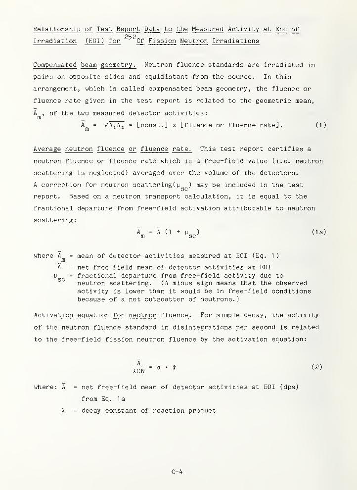
Relationship of Test Report Data to the Measured Activity at End of252
Irradiation (EOI) for Cf Fission Neutron Irradiations
Compensated beam geometry
.
Neutron fluence standards are irradiated in
pairs on opposite sides and equidistant from the source. In this
arrangement, which is called compensated beam geometry, the fluence or
fluence rate given in the test report is related to the geometric mean,
A, of the two measured detector activities:
mA = /A, A, = [const.] x [fluence or fluence rate]. (1)m '
^
Average neutron fluence or fluence rate
.
This test report certifies a
neutron fluence or fluence rate which is a free-field value (i.e. neutron
scattering is neglected) averaged over the volume of the detectors.
A correction for neutron scatteringCy^^) may be included in the test
report. Based on a neutron transport calculation, it is equal to the
fractional departure from free-field activation attributable to neutron
scattering
:
A = A (1 + y ) (la)m sc
where A = mean of detector activities measured at EOI (Eq. 1 )_mA = net free-field mean of detector activities at EOI
M = fractional departure from free-field activity due toneutron scattering. (A minus sign means that the observedactivity is lower than it would be in free-field conditionsbecause of a net outscatter of neutrons.
)
Activation equation for neutron fluence
.
For simple decay, the activity
of the neutron fluence standard in disintegrations per second is related
to the free-field fission neutron fluence by the activation equation:
= 0 • $ (2)XCN
where: A = net free-field mean of detector activities at EOI (dps)
from Eq. la
X = decay constant of reaction product
C-4
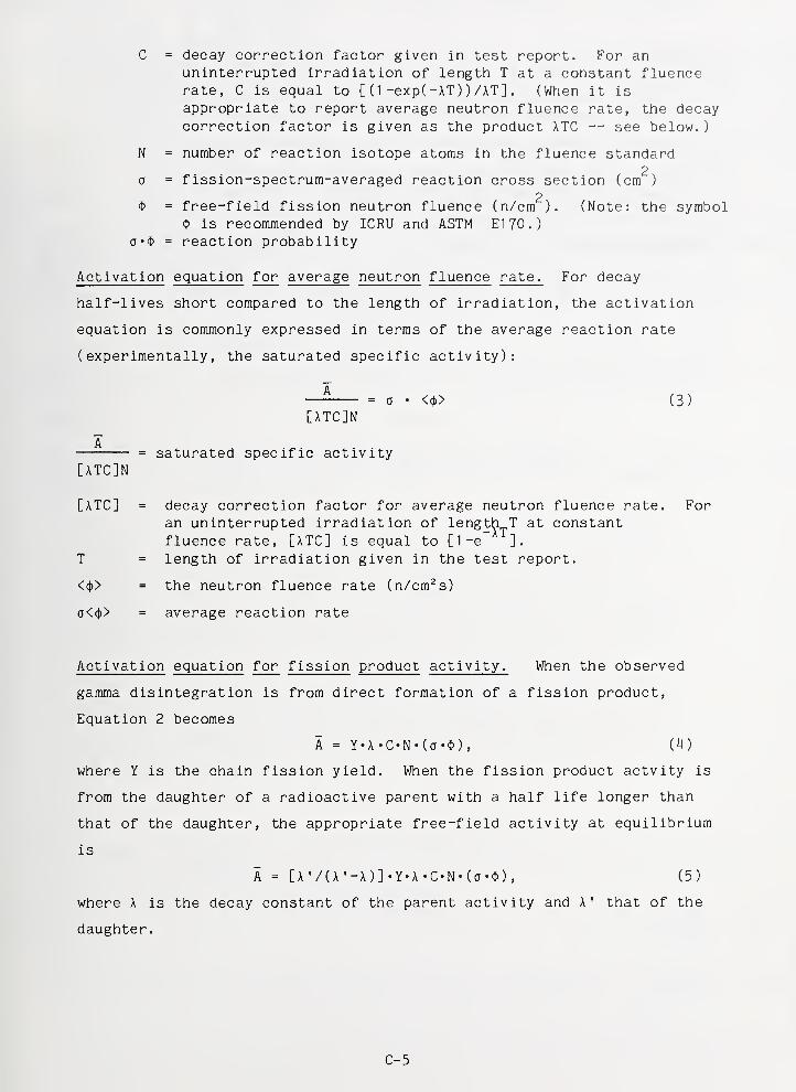
C = decay correction factor given in test report. For anuninterrupted irradiation of length T at a constant fluencerate, C is equal to [ (
1 -exp( -AT ) ) /AT] . (When it is
appropriate to report average neutron fluence rate, the decaycorrection factor is given as the product ATC — see below.)
N = number of reaction isotope atoms in the fluence standard2
0 = fission-spectrum-averaged reaction cross section (cm )
2O = free-field fission neutron fluence (n/cm ). (Note: the symbol
<I> is recommended by ICRU and ASTM El 70.)0'$ = reaction probability
Activation equation for average neutron fluence rate
.
For decay
half-lives short compared to the length of irradiation, the activation
equation is commonly expressed in terms of the average reaction rate
(experimentally, the saturated specific activity):
— = a ' <<t>> (3)
[ATC]N
= saturated specific activity[ATC]N
[ATC] = decay correction factor for average neutron fluence rate. Foran uninterrupted irradiation of lengt^i^T at constantfluence rate, [ATC] is equal to [1-e ].
T = length of irradiation given in the test report.
<<|)> = the neutron fluence rate (n/cm^s)
a<(()> = average reaction rate
Activation equation for fission product activity. When the observed
gamma disintegration is from direct formation of a fission product,
Equation 2 becomes
A = Y«A •C«N«(a'$) , (M)
where Y is the chain fission yield. When the fission product actvity is
from the daughter of a radioactive parent with a half life longer than
that of the daughter, the appropriate free-field activity at equilibrium
is
A = [A '/(A '-A)] -Y-A -C-N- (o-$) , (5)
where A is the decay constant of the parent activity and A' that of the
daughter.
C-5
Recommended Procedure for Establishing a Calibration Factor (x^^)
Use Equations (2) or (3) to derive a free-field neutron fluence or average
fluence rate, respectively, from the measurement of a particular activity
of the neutron sensor. Define a calibration factor for this activity as
the ratio of the NBS certified fission neutron fluence or fluence rate to
the derived neutron fluence or fluence rate. Then, to obtain an NBS
calibrated result for subsequent measurements with this activity, either
multiply observed reaction probability by the calibration factor or divide
the detector cross section by the calibration factor. This calibration
procedure will be most effective if the derived fluence or fluence rate
for the NBS Standard is obtained with the same reaction parameters and
detector cross section set as is used to obtain spectrum-averaged detector
cross-sections for subsequent neutron field measurements.
Revised: November 3, 1986
C-6

NBS-114A iREv. 2.BC)
U.S. DEPT. OF COMM.
BIBLIOGRAPHIC DATASHEET (See instructions)
1. PUBLICATION ORREPORT NO.
NBS/SP-250/13
2. Performing Organ. Report No. 3. Publ icatlon Date
March 1988
4. TITLE AND SUBTITLE
NBS Measurement Services: Activation Foil Irradiation withCalifornium Fission Sources
5. AUTHOR(S)G. P. Lamaze and J. A. Grundl
6. PERFORMING ORGANIZATION (If joint or other than NBS. see instructions)
NATIONAL BUREAU OF STANDARDSU.S. DEPARTMENT OF COMMERCEGAITHERSBURG, MD 20899
7. Contract/Grant No.
8. Type of Report & Period Covered
Final
9. SPONSORING ORGANIZATION NAME AND COMPLETE ADDRESS (Street, City. State, ZIP)
Same as item 6
.
10. SUPPLEMENTARY NOTES
Library of Congress Catalog Card Number 88-600508
I I
Document describes a computer program; SF-185, PIPS Software Summary, is attached.
11. ABSTRACT (A 200-word or less factual sumnr]ary of most significant information,
bibliography or literature survey, mention it here)if document includes a si gnifi cant
This document describes the NBS calibration service 4408nc
(formerly 8.10), which operates in the following way: (i) dosimetrysensors (metal foils, nuclear track detectors, wires, crystals,
etc., supplied by the customer or by NBS) are irradiated to a
certified neutron fluence in a 252Qf spontaneous fission neutronfield (for short lived reaction products, the samples are irradiated
to near saturation and the fluence rate specified), and (ii) the
irradiated dosimetry sensors are shipped to the customer, followed
by a test report stating the fluences or fluence rates and
associated uncertainties. The scope and philosophy of the service,
the neutron field characteristics, irradiation procedures, and the
uncertainties in the reported neutron fluences or fluence rates are
discussed. Typical maximum fluences are of the order of 1 x 10^^
neutrons/cm2 and maximum fluence rates of 1 x lO^ neutrons/cm^ sec,
with combined (la) uncertainties of ± 1,2%.
12. KEY WORDS (Six to twelve entries; alphabetical order; capitalize only proper names; and separate key words by semicolon s)
activation; californium; dosimetry; fast neutrons; fission spectrum;
neutron fluence; neutron fluence rate
13. AVAILABILITY
Unlimited
I I
For Official Distribution. Do Not Release to NTIS
Order From Superintendent of Documents, U.S. Government Printing Office, Washington, D.C.
20402.
Order From National Technical Information Service (NTIS), Springfield, VA. 22161
14. NO. OFPRINTED PAGES
38
15. Price
USCOMM-DC 6043-P80

1
]
I
I
i
I
j
I
i
i
j
I
!
I
!
I
i
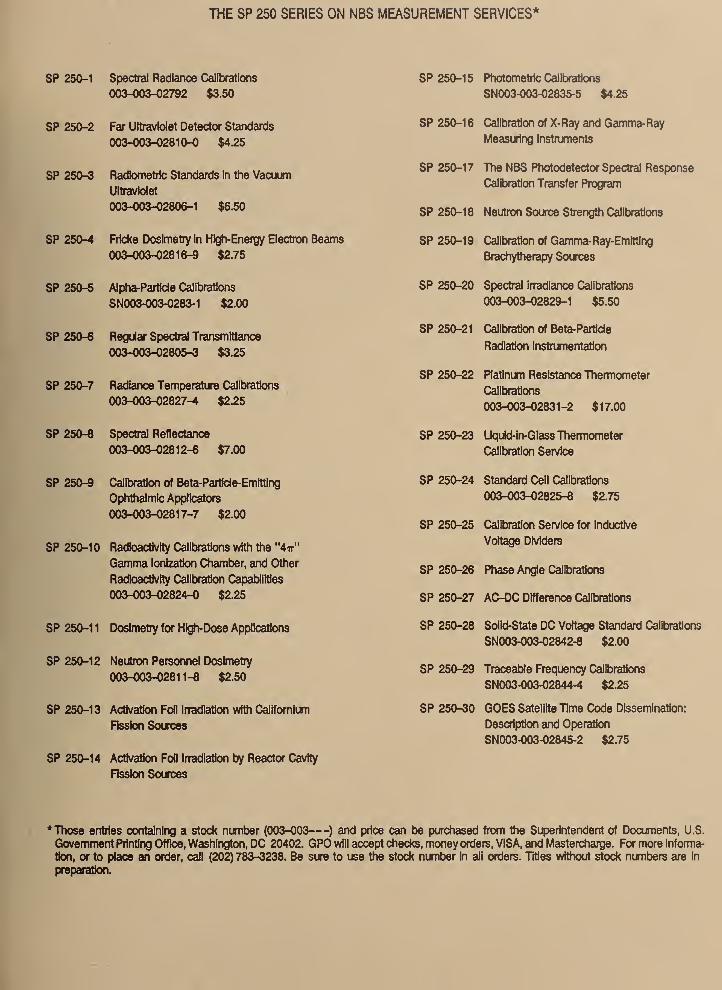
THE SP 250 SERIES ON NBS MEASUREMENT SERVICES*
SP 250-1 Spectral Radiance Calibrations
003-003-02792 $3.50
SP 250-2 Far Ultraviolet Detector Standards
003-003-02810-0 $4.25
SP 250-3 Radiometric Standards In the Vacuum
Ultraviolet
003-003-02806-1 $6.50
SP 250-4 Fricke Dosimetry In High-Energy Electron Beams
003-003-02816-9 $2.75
SP 250-5 Mpha-Partide Calibrations
SN003-003-0283-1 $2.00
SP 250-6 Regular Spectra! Transmtttance
003-003-02805-3 $3.25
SP 250-7 Radiance Temperature Calibrations
003-003-02827-H4 $2.25
SP 250-8 Spectral Reflectance
003-003-02812-6 $7.00
SP 250-9 Calibration of Beta-Partide-Emitting
Ophthalmic Applicators
003-003-02817-7 $2.00
SP 250-10 Radioactivity Calibrations with the "4ir"
Gamma Ionization Chamber, and Other
Radioactivity Calibration Capabilities
003-003-02824-0 $2.25
SP 250-1 1 Dosimetry for Hig^Dose Applications
SP 250-12 Neutron Personnel Doslmetiy
003-003-02811-8 $2.50
SP 250-13 Activation Fofl Irradiation with Californium
Fission Sources
SP 250-14 Activation Foil Irradiation by Reactor Cavity
Fission Sources
SP 250-15 Photometric Calibrations
SN003-003-02835-5 $4.25
SP 250-16 Calibration of X-Ray and Gamma-Ray
Measuring Instmments
SP 250-17 The NBS Photodetector Spectral Response
Calibration Transfer F*rogram
SP 250-18 Neutron Source Strength Calibrations
SP 250-19 Calibration of Gamma-Ray-Emitting
Brachytherapy Sources
SP 250-20 Spectral inadiance Calibrations
003-003-0282^1 $5.50
SP 250-21 Calibration of Beta-Particie
Radiation Instrumentation
SP 250-22 Platinum Resistance Thermometer
Calibrations
003-003-02831-2 $17.00
SP 250-23 Uquid-in-GlassThemiometer
Calitiration Sen/ice
SP 250-24 Standard Cell Calibrations
003-003-02825-8 $2.75
SP 250-25 Calibration Sen/Ice for Inductive
Voltage Dividers
SP 250-26 Phase Angle Calibrations
SP 250-27 AC-DC Difference Calibrations
SP 250-28 Solid-state DC Voltage Standard Calibrations
SN003-003-02842-8 $2.00
SP 250-29 Traceable Frequency Calibrations
SN003-003-02844-4 $2.25
SP 250-30 GOES Satellite Time Code Dissemination:
Description and Operation
SN003-003-02845-2 $2.75
* Those entries containing a stock number (003-003
—
) and price can be purchased from the Superintendent of Documents, U.S.
Government Printing Office, Washington, DC 20402. GPO will accept checks, money orders, VISA, and Mastercharge. For more informa-
tion, or to place an order, call (202)783-3238. Be sure to use the stock number In all orders. Titles without stock numbers are In
preparatkm.
U.S. Department of CommerceNational Bureau of Standards
Gaithersburg, MD 20899
Official Business
Penalty for Private Use $300
75 Years Slimulaling America's Progress19U-19S8