Embed Size (px)
Citation preview
Active Design Methodology of Positioning Precision of Machine Tools
Yanwei XUa and Tancheng XIEb,*
School of Mechatronics Engineering, Henan University of Science and Technology, Luoyang, 471003, China
[email protected], [email protected]
*Corresponding author
Keywords: Machine tool, positioning precision, design methodology
Abstract: Specification of machine precision is an important part of the design specifications and is
essential to machine tools. Conventionally, the precision specification is generally conducted based
on empirical experiences of machine tool manufactures. This may results in a failed design for
insufficient precision specification, or a cost-ineffective design for over specification that will
unnecessarily increase manufacturing cost and difficulty. To give a precise estimation of the
cost-effective precision specification, an innovative machine tools positioning precision active design
methodology is proposed to determine the cost-effective precision specification of machine tools
derived from the machining precision requirements of the work-piece. The methodology consists of
six steps: (1) characterization and selection of formation methods of workpiece features, (2)
determination of motion axes and layout of machine tools, (3) modeling of workpiece surface
formation in terms of the machining principle of the machine tool, (4) machining error modeling
based on the machining model by considering geometric and axial positioning errors of the machine
tool, (5) machining precision modeling based on the machining error model in terms of the geometric
and axial positioning precision of the machine tool, and sensitivity analysis based on the machining
precision model to determined the weights of the machine tool precision indices to machining
precision, and finally (6) allocating the machining precision into machine tool geometric and axial
positioning precision.
Introduction
Machine tool design starts from determination of design specifications. Among the design
specifications precision is an important item and is essential to machine tools. Insufficient precision
specification will cause design failure, while over sufficient precision specification will unnecessarily
increase manufacturing cost and difficulty. Therefore cost-effective precision specification of
machine tools should be critically determined based on specific requirements.
It has been well understood that precision of machine tools is the combined effect of the stiffness
and thermal response of the structure, the precision of the main spindle, the slide ways and the servo
drives, of machine tools [1]. In the last decades, many researches have been conducted on the
precision of machine tools. Schellekens [2] summarized the rules and principles concerning
dimensional metrology, kinematic design, thermal loop, structural loop, metrology frame, drive
offset, force compensation, symmetry and repeatability in design for precision.
It is always necessary to enhance the precision of machine tools for manufacturing of precise
mechanical components. Error compensation and error elimination are two basic methods for
enhancing the precision of machine tools. Ramesh [3] and Ni [4] reviewed error compensation in
machine tools, including source of error, methodology of error elimination, modeling, measurement
and compensation of geometric or kinematic errors, cutting-force induced errors, and thermal errors.
Chen [5] developed a computer-aided error compensation scheme to enhance the accuracy of
multi-axis CNC machine tools by compensating the geometric errors and thermal errors. Wang [6]
proposed an error prediction and compensation system composed of an interpolation algorithm based
on shape functions and developed a practical error compensation system incorporated with an
automatic NC code identifying system to increase the accuracy of multi-axis machines. Tsutsumi [7]
7th International Conference on Manufacturing Science and Engineering (ICMSE 2017)
Copyright © 2017, the Authors. Published by Atlantis Press. This is an open access article under the CC BY-NC license (http://creativecommons.org/licenses/by-nc/4.0/).
Advances in Engineering Research, volume 128
350
presented an algorithm to identify and compensate the positional and angular deviations in 5-axis
machining centers on the basis of the trajectories of simultaneous three-axis and four-axis control
movements. Raksiri [8] proposed a method to compensate the geometric and force errors of a 3-axis
CNC milling machine tool based on the nonlinear error compensation model taking into account
geometric and cutting force induced errors. Yuan [9] presented a real-time error compensation
technique for CNC machining systems, mainly including the general approach for developing
real-time error compensation system, formulation of the error synthesis model, mapping of the
machine errors, optimal modeling, thermal error mode analysis, optimization of the sensor locations,
cutting force-induced error compensation, and compensation control implementation. Lei [10] also
presented a real-time error compensation methods for five-axis CNC machine tool based on the error
identification model by measuring and estimating the unknown link errors in the rotary block of
five-axis CNC machine tools. Choi [11] presented an on-machine measurement and error
compensation system to reduce machining errors of a three-axis machine tool using a touch probe.
Fines [12] calculated error compensation values for axis positioning of a machine tool with artificial
neural networks. Mou [13] presented a systematic approach to enhance machine tool accuracy for
precision manufacturing, including modeling and rapid characterizing of the accuracy of multi-axis
machines, applications of on-machine sensing and analysis, decoupling of process and machine
related errors, and adaptive error correction for more accurate error modeling and compensation.
Ouafi [14] presented an approach for improving the accuracy of multi-axis CNC machines by
software compensation of geometric, thermal and dynamic errors based on a multi-sensor monitoring
system. Zhu [15] presented a method for extraction of repeatable errors from random errors and
compensation of the repeatable errors of machine tool component by incorporating statistical analysis
of the measured data to improve machine tool accuracy. Fan [16] proposed an MBS based universal
kinematics error modeling and analysis method.
Up-to-date literatures on precision issues mostly focused on precision enhancement of machine
tools, no or less concerned the determination of the specification of machine precision. Precision
specification is generally conducted by design experience. This may result in cost-ineffective or failed
precision specification. To mend such a shortage of machine tool design and to give a precise
estimation of the cost-effective precision specification, a methodology named ‘active design’ is
proposed by the authors to determine the cost-effective precision specification of machine tools in
terms of the machining precision requirements of work-piece. The term ‘active design’ means here to
make the machine tools actively adapt to or satisfy the machining precision requirement of the
work-piece in machine tool design. The methodology consists of six steps: (1) characterization and
selection of formation methods of work-piece features, (2) determination of motion axes and layout of
machine tools, (3) modeling of work-piece surface formation in terms of the machining principle of
the machine tool, (4) machining error modeling based on the machining model by considering
geometric and axial positioning errors of the machine tool, (5) machining precision modeling based
on the machining error model in terms of the geometric and axial positioning precision of the machine
tool, and sensitivity analysis based on the machining precision model to determine the weights of the
machine tool precision indices to machining precision, and finally (6) allocating the machining
precision into machine tool geometric and axial positioning precision.
Methodology
The idea of active design of positioning precision of machine tools is to determine the precision
specification of machine tools in terms of the precision requirement of the work-piece to be machined
based on the machining principle, especially for the case that the work-piece surface is formed with
complex principle such as conjugative generation of gear surfaces.
As current work is focused on determination or design of the axial positioning precision
specification of machine tools, following preliminary assumptions are made to simplify the problem
definition: Omit elastic, thermal deformation and geometric errors of the machine tools, and the
Advances in Engineering Research, volume 128
351
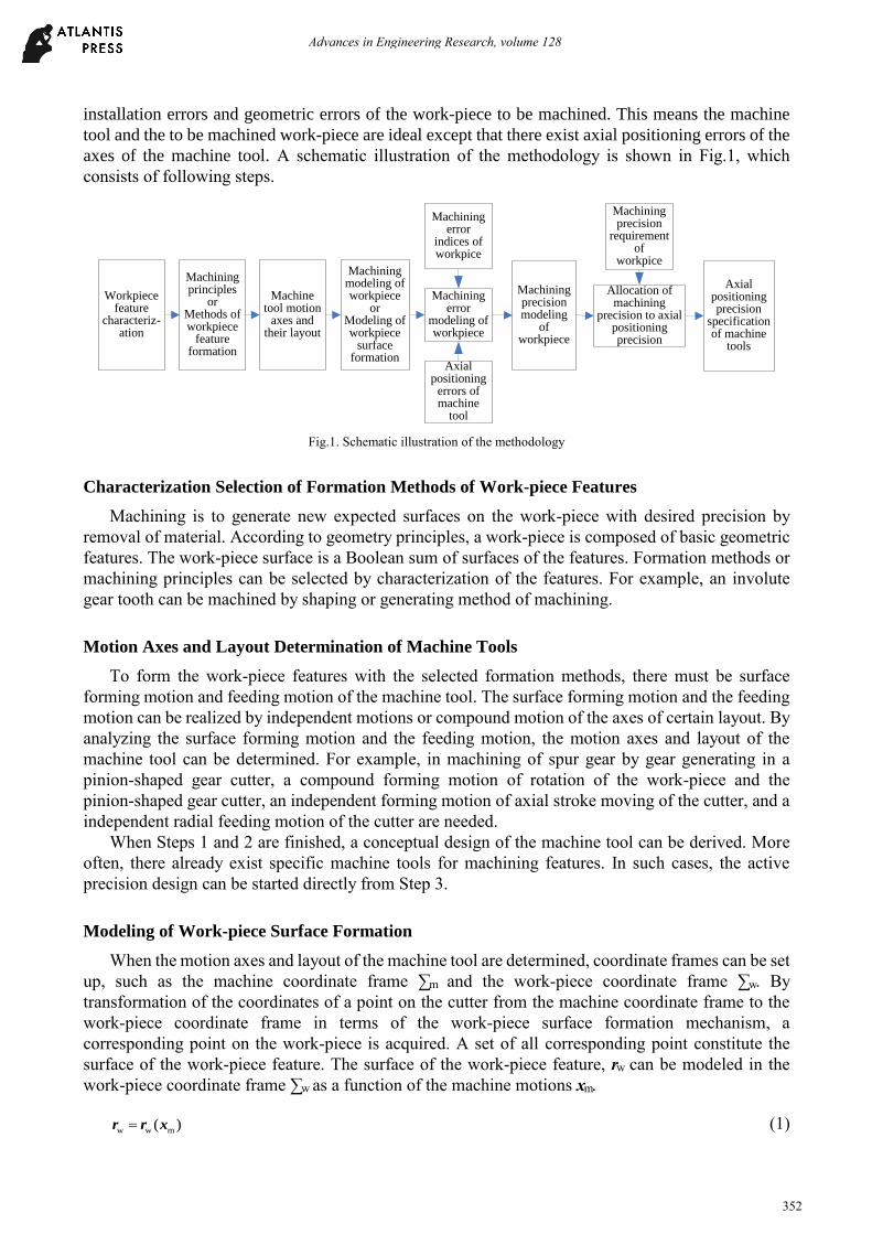
installation errors and geometric errors of the work-piece to be machined. This means the machine
tool and the to be machined work-piece are ideal except that there exist axial positioning errors of the
axes of the machine tool. A schematic illustration of the methodology is shown in Fig.1, which
consists of following steps.
Machining modeling of workpiece
orModeling of workpiece
surface formation
Machining error
modeling of workpiece
Machining error
indices of workpice
Axial positioning
errors of machine
tool
Machining precision
requirement of
workpice
Allocation of machining
precision to axial positioning precision
Axial positioning precision
specification of machine
tools
Machining principles
orMethods of workpiece
feature formation
Workpiece feature
characteriz-ation
Machine tool motion
axes and their layout
Machining precision modeling
of workpiece
Fig.1. Schematic illustration of the methodology
Characterization Selection of Formation Methods of Work-piece Features
Machining is to generate new expected surfaces on the work-piece with desired precision by
removal of material. According to geometry principles, a work-piece is composed of basic geometric
features. The work-piece surface is a Boolean sum of surfaces of the features. Formation methods or
machining principles can be selected by characterization of the features. For example, an involute
gear tooth can be machined by shaping or generating method of machining.
Motion Axes and Layout Determination of Machine Tools
To form the work-piece features with the selected formation methods, there must be surface
forming motion and feeding motion of the machine tool. The surface forming motion and the feeding
motion can be realized by independent motions or compound motion of the axes of certain layout. By
analyzing the surface forming motion and the feeding motion, the motion axes and layout of the
machine tool can be determined. For example, in machining of spur gear by gear generating in a
pinion-shaped gear cutter, a compound forming motion of rotation of the work-piece and the
pinion-shaped gear cutter, an independent forming motion of axial stroke moving of the cutter, and a
independent radial feeding motion of the cutter are needed.
When Steps 1 and 2 are finished, a conceptual design of the machine tool can be derived. More
often, there already exist specific machine tools for machining features. In such cases, the active
precision design can be started directly from Step 3.
Modeling of Work-piece Surface Formation
When the motion axes and layout of the machine tool are determined, coordinate frames can be set
up, such as the machine coordinate frame ∑m and the work-piece coordinate frame ∑w. By
transformation of the coordinates of a point on the cutter from the machine coordinate frame to the
work-piece coordinate frame in terms of the work-piece surface formation mechanism, a
corresponding point on the work-piece is acquired. A set of all corresponding point constitute the
surface of the work-piece feature. The surface of the work-piece feature, rw can be modeled in the
work-piece coordinate frame ∑w as a function of the machine motions xm.
w w m( )r r x (1)
Advances in Engineering Research, volume 128
352
Modeling of Work-piece Machining Error
By introducing positioning errors of the motion axes ∆xm into Eqn. (1), a machined surface with
error can be obtained. The machining error of the work-piece surface can be approximately expressed
as
w
w w m m m m m
m
( , )
rr r x x x K x
x (2)
Generally the components of ∆xm, ∆xmi (i = 1,2,…,n; n is the number of the axes of the machine
tool.) are independent of each other and are normal distributed. In term of the principle of error
synthesis, variance of the machining error, σw will be
2 2 2
w m
1
n
i i
i
K
(3)
where σi is the variance of positioning error of axis i, ∆xmi .
Modeling of Work-piece Machining Precision
In terms of the six-sigma (6σ) principle, machine precision of work-piece, Aw (maximum of
absolute value of error) can be defined as
w w6A (4)
In terms of International Standard ISO 230-2:2006(E) of “Test code for machine tools —Part 2:
Determination of accuracy and repeatability of positioning numerically controlled axes”, the
positioning precision of a motion axis when the system error is calibrated to zero, Ai can be defined as
2 2i iA (5)
Substitute Eqn. (4) into Eqn. (3), then relationship between the machining precision of the
work-piece Aw and the positioning precision Ai of the axes is
2 2 2
w m
1
9
4
n
i i
i
A K A
(6)
Allocating of Machining Precision to Axial Positioning Precision
By reference of the principle of equal effects [32-34] of tolerance allocation, assuming the
positioning precisions of the motion axes follow such relationships as
2 2 2 2
m m ( )i i j jK A K A i j (7)
Substitute Eqn. (7) into Eqn. (6), then the positioning precision Ai of motion axis i of the machine tool
is
w
m
2
3i
i
AA
n K (8)
When finishing this step, the positioning precision specification is acquired. As some other errors as
geometric error, elastic and thermal deformation of the machine tool, are omitted in the modeling of
work-piece machining error, the results of the current modeling only give a reference limits of
positioning precisions of the motion axes. A safety discount should be taken on the acquired
positioning precision specification when used to machine tool design.
Advances in Engineering Research, volume 128
353
Acknowledgement
The authors are grateful for the financial support of the National Natural Science Foundation of
China (51305127) and the scientific research key project fund of the Education Department Henan
Province of China (14A460018).
References
[1] Rao, S. B., 1997. “Metal Cutting Machine Tool Design—A Review”. Journal of Manufacturing Science
and Engineering, 119, pp. 713-716.
[2] Schellekens, N. R., 1998. “Design for Precision: Current Status and Trends”. ClRP Annals, 47(2), pp.
557-586.
[3] Ramesh, R., Mannan, M. A., and Poo, A. N., 2000, “Error Compensation in Machine Tools — A Review:
Part I: Geometric, Cutting-force Induced and Fixture-dependent Errors”. International Journal of
Machine Tools and Manufacture, 40(9), pp. 1235-1256.
[4] Ni, J., 1997. “A Perspective review of CNC Machine Accuracy Enhancement Through Real-time Error
Compensation”. China Mechanical Engineering, 8 (1), pp. 29-33.
[5] Chen, J-S., 1995. “Computer-aided Accuracy Enhancement for Multi-axis CNC Machine Tool.
International Journal of Machine Tools and Manufacture, 35(4), pp. 593-605.
[6] Wang, S-M., Liu, Y-L., and Kang, Y., 2002. “An Efficient Error Compensation System for CNC
Multi-axis Machines”. International Journal of Machine Tools and Manufacture, 42(11), pp. 1235-1245.
[7] Tsutsumi, M. Saito, A., 2003. “Identification and Compensation of Systematic Deviations Particular to
5-axis Machining Centers”. International Journal of Machine Tools and Manufacture, 43(8), pp. 771-780.
[8] Raksiri, C., Parnichkun, M., 2004. “Geometric and Force Errors Compensation in a 3-axis CNC Milling
Machine”. International Journal of Machine Tools and Manufacture, 44(12-13), pp. 1283-1291.
[9] Yuan, J., Ni, J., 1998. “The real-time Error Compensation Technique for CNC Machining Systems”.
Mechatronics, 8(4), pp. 359-380.
[10] Lei, W. T., Hsu, Y. Y., 2003. “Accuracy Enhancement of Five-axis CNC Machines Through Real-time
Error Compensation”. International Journal of Machine Tools and Manufacture, 43(9), pp. 871-877.
[11] Choi, J. P., Min, B. K., and Lee, S. J., 2004. “Reduction of Machining Errors of a Three-axis Machine
Tool by On-machine Measurement and Error Compensation System”. Journal of Materials Processing
Technology, 155-156, pp. 2056-2064. Proceedings of the International Conference on Advances in
Materials and Processing Technologies: Part 2.
[12] Fines, J. M., Agah, A., 2008. “Machine Tool Positioning Error Compensation Using Artificial Neural
Networks”. Engineering Applications of Artificial Intelligence, 21(7), pp. 1013-1026.
[13] Mou, J., 1997. “A systematic Approach to Enhance Machine Tool Accuracy for Precision Manufacturing,
International Journal of Machine Tools and Manufacture, 37(5), pp. 669-685.
[14] Ouafi, A. E., Guillot, M., and Bedrouni, A., 2000. “Accuracy Enhancement of Multi-axis CNC
Machines Through On-line Neuron Compensation”. Journal of Intelligent Manufacturing, 11(6), pp.
535-545.
[15] Zhu, W., Wang, Z., and Yamazaki, K., 2010. “Machine Tool Component Error Extraction and Error
Compensation by Incorporating Statistical Analysis”. International Journal of Machine Tools and
Manufacture, 50(9), pp. 798-806.
[16] Fan, J. W., Guan, J. L., and Wang, W. C. et al, 2002. “A Universal Modeling Method for Enhancement the
Volumetric Accuracy of CNC Machine Tools. Journal of Materials Processing Technology, 129(1-3), pp.
624-628.
Advances in Engineering Research, volume 128
354