Embed Size (px)
Citation preview

THESIS FOR THE DEGREE OF LICENTIATE OF ENGINEERING
IN
MACHINE AND VEHICLE SYSTEMS
Active Muscle Responses in a
Finite Element Human Body Model
JONAS ÖSTH
Vehicle Safety Division Department of Applied Mechanics
CHALMERS UNIVERSITY OF TECHNOLOGY Göteborg, Sweden, 2010
Active Muscle Responses in a Finite Element Human Body Model JONAS ÖSTH ©JONAS ÖSTH, 2010 THESIS FOR LICENTIATE OF ENGINEERING no. 2010:12 ISSN 1652-8565 Department of Applied Mechanics Chalmers University of Technology SE-412 96 Göteborg Sweden Telephone +46 (0)31-772 1000 Chalmers Reproservice Göteborg, Sweden, 2010

i
Active Muscle Responses in a Finite Element Human Body Model
Jonas Östh Vehicle Safety Division, Department of Applied Mechanics
Chalmers University of Technology
Abstract The development of automotive safety systems is moving towards an integration of systems that are active before and during an impact. Consequently, there is a need to make a combined analysis of both the pre-crash and the in-crash phases, which leads to new requirements for Human Body Models (HBMs) that today are used for crash simulations. In the pre-crash phase the extended duration makes the active muscle response a factor that must be taken into account in the HBM to correctly simulate the human kinematics. In this thesis, the active muscle response is modeled using a feedback control strategy with Hill-type line muscle elements implemented in a Finite Element (FE) HBM. A musculoskeletal modeling and feedback control method was developed and evaluated, with simulations of the human response to low level impact loading of the arm in flexion-extension motion. Then, the method was implemented to control trunk and neck musculature in an FE HBM, to simulate the occupant response to autonomous braking. Results show that the method is successful in capturing active human responses and that a variety of responses in volunteer tests can be captured by changing of control parameters. The proposed method, to model active muscle responses in an FE HBM using feedback control, makes it possible to conduct a pre-crash simulation in order to determine the initial conditions for an in-crash simulation with an FE HBM. It also has a large potential to extend the use of FE HBMs to the simulation of combined pre-crash and in-crash scenarios, crash scenarios of longer duration such as roll-over accidents and, eventually, multiple events. Keywords: active muscle; feedback control; posture maintenance; reflexive response; autonomous braking; finite element; human body model

ii

iii
Sammanfattning Utvecklingen av fordonssäkerhetssystem går mot att system som är aktiva under en kollsion integreras med system som är aktiva före kollisionen. Därför har det uppstått ett behov av att kunna utföra analyser av båda dessa förlopp, något som leder till nya krav på humanmodeller som idag enbart används för krocksimulering. Förloppet som föregår en kollision är betydligt längre än själva kollisionen. Detta gör att man här måste ta hänsyn till effekten av muskelreaktioner hos den åkande för att korrekt kunna simulera dess rörelse. I denna avhandling modelleras muskelreaktioner i en Finit Element (FE) humanmodell. En-dimensionella muskelelement av Hill-typ styrs med hjälp av ett återkopplat reglersystem. En metod för att göra detta utvecklades med hjälp av en modell av armbågen. Armbågsmodellen utvärderades genom simuleringar av responsen på plötsliga kraftimpulser hos en volontär. Sedan användes metoden för att reglera muskulaturen i korsrygg och nacke för att simulera rörelsen hos bilpassagerare som utsattes för autonom inbromsning. Resultaten av dessa studier visar att metoden är framgångsrik i att fånga den mänskliga responsen i dessa testfall och att olika beteenden kan fångas genom att modellens reglerparametrar varieras. Den föreslagna metoden, att använda ett återkopplat reglerssystem för att modellera muskelreaktioner i en FE humanmodell, gör det möjligt att genomföra en simulering av förloppet före en kollision för att bestämma begynnelsevillkor för en krocksimulering med samma modell. Metoden uppvisar också en stor potential för att utöka användningsområdet för FE humanmodeller till att också innefatta kombinerade analyser med både förloppet före kollision och själva kollisionen. Det blir också möjligt att simulera andra olycksscenarior som har ett längre förlopp, så som t.ex. roll-over olyckor och i förlängningen olyckor med fler efterföljande kollisioner, s.k. multiple events.

iv
Preface and Acknowledgements The work presented in this licentiate thesis was conducted at the Division of Vehicle Safety, Department of Applied Mechanics, Chalmers University of Technology in Gothenburg, Sweden. It was funded by SAFER – The Vehicle and Traffic Safety Centre at Chalmers, as project B8: Development of Active HBM in Frontal Impact Situations. The overall goal of the research project is to develop a robust HBM that has the capability to maintain its initial posture and to model the human pre–crash response in the sagittal plane. The SAFER partners in this project are Autoliv, Volvo Car Corporation, Saab Automobile, and Volvo Technology. I would like to thank all of those who have given me help and support with the work presented in this thesis:
• First my academic supervisors Professor Jac Wismans, Assistant Professor Karin Brolin and Assistant Professor Johan Davidsson for their advice.
• I am grateful to the industrial partners in the Active HBM project: Bengt Pipkorn, Ph.D., at Autoliv Research, Mats Lindquist, Ph.D., at Saab Automobile, Professor Lotta Jakobsson and Merete Östman at Volvo Car Corporation, Stefan Thorn, Ph.D. and Fredrik Törnvall, Ph.D., at Volvo Technology.
• Assistant Professor Riender Happee at Delft University of Technology who provided valuable help with Paper 1 and many constructive ideas on modeling of human control.
• I thank Lora Sharp McQueen for the language editing of Paper 1 and the thesis. • My colleagues at the Vehicle Safety Division who have helped me with many issues. • Last but not least, I want to thank my wife Katarina and our children Selma and Joakim
for their love and support.
Jonas Östh Göteborg, December 2010

v
Appended Papers
1. Östh J, Brolin K, Happee R.
Active Muscle Response using Feedback Control of a Finite Element Human Arm Model.
Paper accepted (October 25th 2010) for publication in Computer Methods in
Biomechanics and Biomedical Engineering.
2. Östh J, Brolin K, Carlsson S, Wismans J, Davidsson J.
The Occupant Response to Autonomous Braking: A Modeling Approach That Accounts for Active Musculature.
Manuscript submitted to Traffic Injury Prevention.

vi
Acronyms ATD Anthropometric Test Device, also known as a crash test dummy
C1–C7 Cervical vertebrae numbered from the atlas (C1) in the caudal direction
CE Contractile Element
CNS Central Nervous System
EMG Electromyogram
ESC Electronic Stability Control
FE Finite Element
HBM Human Body Model
L1–L5 Lumbar vertebrae numbered in the caudal direction
MB MultiBody
PCSA Physiological Cross-Sectional Area
PE Parallel Elastic element
PMHS Post Mortem Human Subject
PID Proportional, Integral, and Derivative
SE Series Elastic element
T1–T12 Thoracic vertebrae numbered in the caudal direction
THUMS Total HUman Model for Safety

vii
Table of Contents Abstract ............................................................................................................................................. i
Sammanfattning ............................................................................................................................. iii
Preface and Acknowledgements ..................................................................................................... iv
Appended Papers .............................................................................................................................. v
Acronyms ........................................................................................................................................ vi
Notation ........................................................................................................................................ viii
1 Introduction .............................................................................................................................. 1
1.1 Background ........................................................................................................................ 1
1.2 Aim .................................................................................................................................... 2
2 The Modeling of Active Muscle Responses ............................................................................ 3
2.1 Mechanical Properties of Muscles ..................................................................................... 3
2.2 Human Motor Control ....................................................................................................... 5
3 Survey of HBMs for Crash Simulations .................................................................................. 7
4 Summary of Paper 1 ............................................................................................................... 10
5 Summary of Paper 2 ............................................................................................................... 11
6 Discussion .............................................................................................................................. 12
7 Future Work ........................................................................................................................... 15
8 Conclusions ............................................................................................................................ 16
9 References .............................................................................................................................. 17
Appendix A: Musculoskeletal Model ........................................................................................... A1
Muscle Geometry .................................................................................................................... A14
References ............................................................................................................................... A19
Appendix B: Feedback Control ..................................................................................................... B1

viii
Notation
Cleng fv constant for the transition between concentric and eccentric shortening
Cmvl fv constant for the eccentric asymptote
Cshort fv constant for concentric shortening
D Parallel element damping
e(t) Control error
fv Contractile element force-velocity relation
kd Proportional control gain
ki Integral control gain
kp Derivative control gain
l Muscle length
lopt Optimum muscle length
PEmax Parallel element strain at σmax
r(t) Control reference value
Tde Neural delay
Tf Control derivative lowpass filter time constant
Tnaa Muscle activation dynamics time constant for activation
Tnad Muscle activation dynamics time constant for deactivation
Tne Muscle activation dynamics time constant for neural exctitation
V Muscle shortening velocity
Vmax Maximum muscle shortening velocity
y(t) Process value
σmax Muscle maximum isometric stress

1
1 Introduction
The mobility provided by automotive transports is essential to our society and most people’s lives are affected by it every day. However, it comes at a price as accidents in the transport systems are common. The number of traffic related fatalities and injuries worldwide was estimated to be 1.2 million fatalities and up to 50 million injuries annually in the year 2004, with a predicted increase of 65% between years 2000 and 2020 (Peden et al. 2004). In this context, the importance of traffic safety research and the development of automotive safety systems is quite clear.
1.1 Background The development of safety systems requires tools to evaluate the performance of the system. Since the objective of automotive safety systems is to protect the vehicle occupants and humans outside the vehicle, the evaluation criteria should show how well the injuries sustained in an impact can be mitigated by the system. To make this evaluation is a challenging task, as humans can not be subjected to injurious loads in physical testing. Therefore, human surrogates are needed for these types of tests. For physical testing, Anthropometric Test Devices (ATDs), also known as crash-test dummies, are developed based on data from Post Mortem Human Subjects (PMHS) for example, and used for this task. As the development process is iterative, a better system performance can be achieved if a large number of tests can be conducted to allow for parameter and optimization studies. Therefore, as an alternative to ATDs, several mathematical models of ATDs (Eriksson 2000; Noureddine et al. 2002; Mohan et al. 2010) and Human Body Models (HBMs) have been developed. The difference between mathematical models of ATD and HBMs is that the objective of the ATD model is to replicate the response of the dummy, while the objective of the HBM is to replicate the response of the human body directly. Mathematical HBMs are therefore typically more complex, with more human-like geometry and material properties. The advantage of HBMs is that they allow for increased biofidelity and offer the potential for study of injury mechanisms at tissue level (Wismans et al. 2005). The HBMs can be full body models (Happee et al. 1998; Robin 2001; Iwamoto et al. 2002) or models of body parts (de Jager 1996; Kleiven 2002; Behr et
al. 2006).
2
Current HBMs can be used to optimize the performance of passive safety systems through simulation of various crash events. The most widespread passive safety system is probably the seat belt, which has been shown to reduce overall casualties in vehicle crashes by about 40% (Wodzin et al. 2006). More recently, automotive safety has seen the introduction of active safety systems such as Electronic Stability Control (ESC) programs. This type of system has been shown to reduce vehicle crashes significantly (Frampton and Thomas 2007), thereby preventing accidents and casualties. The current development trend for automotive safety systems is to combine these two types of systems to achieve integrated systems that are active both during impact (like the seat belt) and in the pre-crash phase (like the ESC) to improve vehicle safety even further (Aparicio et al. 2006). This generates new requirements for HBMs that are to be used for the evaluation of these systems. The HBM must also be able to respond with human-like kinematics in the pre-crash phase when integrated safety systems will be activated. In general, this is not possible with current HBMs as they have been developed only for use in in-crash simulations and do not account for the active muscle response. The duration and the loading level in the pre-crash phase are such that the active muscle response is an important factor in the kinematic response of an occupant, which is why it must be included to model the occupant kinematics accurately.
1.2 Aim The integration of passive and active systems gives rise to the need for a tool that can evaluate the performance of automotive safety systems in both the pre-crash phase and the following in-crash phase. To simulate the human pre-crash response with an HBM, it is necessary to model the muscle activation to get biofidelic simulation results. The aim of this thesis is to develop and evaluate a method to model the active muscle response with an HBM.

3
2 The Modeling of Active Muscle Responses The active human response is controlled by the Central Nervous System (CNS) and motions are actuated by the musculoskeletal system. Therefore, to be able to model the active human response a mechanical model of the musculature is essential.
2.1 Mechanical Properties of Muscles Two muscle modeling approaches are common in the literature: detailed biophysical cross-bridge models (Huxley 1957) and phenomenological Hill-type models (Hill 1938 & 1970; Winters and Stark 1985). The Hill-type models are more suitable than the cross-bridge ones to model transient events (van den Bogert et al. 1998); they also have the advantage of a lower complexity. In a Hill-type model the mechanical properties of the muscle tissue are described by the three elements shown in Figure 1. The Parallel Elastic (PE) element represents the stiffness of the passive muscle tissue, and the PE element is usually modeled with non-linear characteristics as shown in Figure 2. The PE element can also include a rate dependant term, modeling the viscoelastic properties of the passive muscle tissue. The Series Elastic (SE) element can be considered to be tendons by which the muscle is connected to the skeletal structure. Although the SE and PE elements have a similar shape of the force-length relation, the SE element is usually approximately ten times stiffer.
Figure 1. Hill-type muscle model. CE: Contractile Element; PE: Parallel Elastic element; SE: Series Elastic element.
Figure 2. Force-length relation of active muscle force (solid line) and passive elastic force (dashed line).
CE
PE
SE
(Tendon)
4
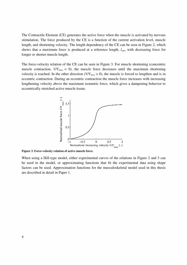
The Contractile Element (CE) generates the active force when the muscle is activated by nervous stimulation. The force produced by the CE is a function of the current activation level, muscle length, and shortening velocity. The length dependency of the CE can be seen in Figure 2, which shows that a maximum force is produced at a reference length, lopt, with decreasing force for longer or shorter muscle length. The force-velocity relation of the CE can be seen in Figure 3. For muscle shortening (concentric muscle contraction, V/Vmax < 0), the muscle force decreases until the maximum shortening velocity is reached. In the other direction (V/Vmax > 0), the muscle is forced to lengthen and is in eccentric contraction. During an eccentric contraction the muscle force increases with increasing lengthening velocity above the maximum isometric force, which gives a dampening behavior to eccentrically stretched active muscle tissue.
Figure 3. Force-velocity relation of active muscle force.
When using a Hill-type model, either experimental curves of the relations in Figure 2 and 3 can be used in the model, or approximating functions that fit the experimental data using shape factors can be used. Approximation functions for the musculoskeletal model used in this thesis are described in detail in Paper 1.

5
2.2 Human Motor Control The action of the muscles in the human body is coordinated by the CNS, which acts as the controller of the human body. The function of the CNS and of human motor control is complex but, with simplified modeling approaches, certain aspects of human motor control can be captured. Voluntary motion and goal directed movement require sophisticated modeling strategies (Gerdes and Happee 1994; Kawato 1999), however it has been shown that reflexive responses and postural control tasks are possible to model using feedback control (Barin 1989; Brouwn 2000; Kou 2005). In a feedback control system, the actuator control signal is generated as a response to changes in the reference signal or to external disturbances. An introduction to feedback control is given in Appendix B. For postural control tasks and reflexive responses, the reference can be considered to be constant and the CNS to be counteracting external disturbances. Such disturbances could be inertial loading due to acceleration or force perturbations. The response of a feedback control system depends on the properties of the subsystems that make up the closed loop. In a closed loop model of the human CNS motor control, the dynamics are determined by the inertia of the limbs controlled, the dynamics of the muscle activation process and the dynamics of the muscle model as described in Section 2.1. The closed loop model could also include dynamics on the controller side, such as transmission delays, sensor dynamics, and a muscle recruitment scheme (Dul et al. 1984), which determines what muscles are activated to perform a certain task. The transmission delay in the nervous system is associated with the signal processes of the nerves and, to a large extent, with the transmission time it takes for a neural signal to travel from the receptors to the CNS and from the CNS to the muscles (Smith et al. 1996). Therefore, it is longer the further away from the brainstem the muscles being controlled are situated. For instance the neural delays of the muscles of the arm have been estimated to range from 30 ms for the shoulder muscles to 40 ms for the muscles of the wrist (de Vlugt et al. 2006). There is a large amount of sensory information available for the CNS to use in the motor control process. Somatosensory receptors such as joint angle receptors, Golgi tendon organs and muscle spindles provide information on the current state of individual joints and muscles (Smith et al. 1996). For postural control, in which the CNS balances the upright human body or keeps a limb in a certain position, more information is involved; the vestibular receptors of the ear act as angular velocity sensors and linear accelerometers; visual input provide input on body rotation and translation (Kou 2005). The dynamics of these sensory systems is usually modeled with a transfer function that characterizes the properties of the various receptors (Agarwal and Gottlieb 1984; Brouwn 2000; Kou 2005; de Vlugt 2006).
6
The human musculoskeletal system is mechanically redundant with regard to the number of muscles present (Dul et al. 1984). Since there are several muscles crossing each joint, there are more muscles than necessary to perform each possible motion. For the modeling of musculoskeletal systems, there are various strategies used to determine which muscles should be activated to achieve a certain task. A common method is to use an optimization strategy to specify, in addition to the requested torque or motion, that the energy spent should be minimized (Dul et al. 1984; Chancey et al. 2002).

7
3 Survey of HBMs for Crash Simulations Today, two techniques are used to model the response of the human body in impact simulations. The first is the MultiBody (MB) dynamics approach, in which the system is modeled with a set of both rigid and flexible bodies with inertial properties, interconnected with joints defined by kinematic constraints (Wismans et al. 2005). The strength of this type of model is that human body kinematics can be simulated very efficiently with short run times, allowing for a large number of simulations. The second approach is to use the Finite Element (FE) method. In this method the body modeled is divided into smaller domains, elements that are defined by a set of nodal points, and the inertial properties of the body are assigned to the nodes. Approximating functions, based on the type of element formulation chosen, are used to solve the differential equations that define the solid mechanics problem of the body. A constitutive material law is applied to relate element deformation to internal forces. An advantage of the FE method is that the internal stresses and strains are available for the evaluation of injury risk, which can then be performed at tissue level. Muscle properties have previously been modeled in HBMs. The simplest representation of musculature is just the inclusion of elements without any activation, modeling the passive elastic and damping response of the muscle tissue (Jost and Nurick 2000; Robin 2001; Toyota Motor Corporation 2008). In other models, limited active muscle responses have been modeled by various approaches to determine the muscle activation levels that represent the nervous stimuli to the muscle. Several models (de Jager 1996; Wittek 2000; van der Horst 2002; Brolin et al. 2005) have accounted for the influence of active behavior by application of a maximum activation starting at a specified time in the simulation. This models a reflexive response which is determined by the choice of time constants in the activation dynamics model or by the shape of the pre-defined activation level curve. With this approach in a MB neck model, de Jager (1996) showed the importance of active muscles to capture the human head-neck response in frontal and lateral impacts; the same model was later refined and employed in rear-end impacts and the importance of active muscles was yet again shown by van der Horst (2002). Wittek (2000) and Brolin et al. (2005) used this approach together with Hill-type line muscle elements in an FE neck model. They studied the protective effect of the neck muscles on cervical facet joint injuries in rear-end impacts and soft tissue injuries in frontal and side impacts, respectively.

8
Chancey et al. (2003) developed a MB neck model with detailed muscles and studied the effect of muscle activation on tensile loading of the neck for two sets of muscle activations. The muscle activations evaluated were determined with an optimization scheme that gave an initial stable posture for relaxed and maximal muscle tension. The neck stabilizing muscle activation levels reported by Chancey et al. (2003) were used as a starting point to find load case specific stabilizing activations in a study with an FE neck model conducted by Brolin et al. (2008). The model was then applied to evaluate the influence of muscle tension on spine injuries in helicopter accident scenarios. A third method to determine muscle activation levels was applied by Behr et al. (2006), Sugiyama et al. (2007), and Chang et al. 2008. These three studies applied muscle activation levels from normalized Electromyogram (EMG) measurements in emergency braking experiments and compared the injury risk in an active state and in a relaxed state using an FE HBM. In all of the studies above, muscle activations have been pre-defined before the simulations. The activation levels determined from experiments have the advantage that actual human-like activation patterns are reproduced in simulation. Unfortunately, the resolution of muscle activation levels derived from experiments is not high enough to discriminate individual muscle activations, due to limitations in recording the EMG signal. However, such detail is provided by the optimization process conducted by Chancey et al. (2003). The muscle activations can be derived by using additional criteria, for example that the energy spent by the muscles should be minimized while a stabilizing task is performed and individual muscle activations will be provided. This method works well for the initial stabilizing task, and it could also be conducted for a dynamic event if accurate kinematic data were available. Due to the iterative nature of the optimization process and the complexity of the HBM though, this is unlikely to be feasible. The activation function used to represent a reflexive response (de Jager 1996; Wittek 2000; van der Horst 2002) could be validated for the individual simulation setup by comparison with experimental data. However, actual human reflexive responses are closed loop (Kou, 2005), not open loop as modeled in these scenarios, which is why the adaptivity of the model to other simulation scenarios would be improved if the actual feedback reflexive response could be captured.

9
Closed loop feedback control to determine muscle activation levels during simulation has been tried in more recent studies with MB HBMs. Cappon et al. (2007) focused on the problem of HBM postural stability in relatively long duration simulations resulting from pre-crash and roll-over situations. To achieve postural stability of an MB HBM, Proportional, Integral, and Derivative (PID) controllers were implemented with torque actuators for each individual vertebral joint. Control parameters were derived from volunteer impactor tests and the model was applied to evaluate the response in a roll-over situation. Budsziewski et al. (2008) made an attempt to use feedback PID control of an upper extremity model. Fraga et al. (2009) used feedback PID control of line muscle elements to stabilize the head of a motorcycle rider in lateral and longitudinal maneuvers for MB simulations. They concluded that their model appears to capture the resulting head kinematics of a volunteer of average awareness when braking a motorcycle. Furthermore, they stated that the model is promising for the development of advanced restraint systems for motorcycle riders, and that it is a step towards fully active HBMs. The head-neck model used by Fraga et al. (2009) was further developed by Nemirovsky and van Rooij (2010) by the implementation of a biofidelic postural controller for the head-neck complex, with the aim of controlling flexion-extension, lateral flexion, and rotation of the head. The motions were decoupled by a muscle recruitment strategy, which would ensure that only one degree of freedom was influenced by each controller; only the model response in flexion-extension was evaluated though. Along with three PID controllers for the three head rotation degrees of freedom a variable co-contraction ratio controller was implemented. The co-contraction ratio was important for the resulting closed loop response, as muscular co-contraction makes a large contribution to the damping of the closed loop system. As in the MB HBM studies above, Almeida et al. (2009) incorporated active response in a MB model; however, this was not one of an actual human, but a model of the ATD THOR. In similarity to Fraga et al. (2009), the motion of the head-neck complex was controlled with PID controllers, but instead of line muscle elements, joint torque was applied for actuation of the control signals. Although the numerical study by Almeida et al. (2009) treats the same problem as the other MB studies above, the goal is different: it is to eventually also incorporate active responses in ATDs for use in physical testing. To the best of my knowledge, there have not been any studies published in which closed loop feedback control is used to model active muscle responses in FE HBM.

10
4 Summary of Paper 1 The aim of Paper 1 is to address the challenges of implementing feedback control of a muscle material model in an FE HBM. A musculoskeletal model was developed, using the right arm and upper extremity of the FE HBM THUMS (Toyota Motor Corporation 2008), but replacing the original contact based elbow joint of the HBM with a rigid body revolute joint. Furthermore, volunteer tests with low impact loads resulting in elbow flexion motions were conducted. Results showed that the musculoskeletal model strength and passive stiffness characteristics were comparable to experimental data in the literature. The feedback control loop implemented was able to stabilize the model in simulations with gravity, thus the model could maintain posture. Simulation of volunteer experiments showed that, by a variation of controller gains, different kinds of instructions to the volunteer could be captured by the model. Simulations with the original contact based joint showed that lower controller gains were necessary due to an increase in phase lag, and that 3D joint motions had to be controlled with a 1D reference signal. The result from simulations of volunteer responses, indicates that by variation of the controller gains it is possible to simulate, with an FE HBM, the various active muscle responses that can be expected in the pre-crash phase. Comparison of simulations with the two joints in the model showed that feedback control can be used in an FE HBM, but that joint definitions should be modeled in more detail to capture human-like passive joint properties. In conclusion, the study in Paper 1 showed that it is possible to use feedback control of a non-linear musculoskeletal model in an FE environment to obtain a posture maintaining HBM and to simulate reflexive muscle responses.

11
5 Summary of Paper 2 The aim of Paper 2 is to model the human kinematic response to autonomous brake interventions. Paravertebral muscles of the lumbar and cervical spine, superficial muscles of the neck, and the abdominal muscles were added to the FE HBM THUMS (Toyota Motor Corporation 2008) and active control was implemented using three PID controllers, for the head, the neck, and the lumbar rotation angles. Volunteer kinematic data from occupants in the passenger seat in autonomous braking interventions was sampled from a study made by Carlsson and Davidsson (2010) for comparison with HBM simulation results. The results showed that the volunteers tried to maintain their line of sight during the braking intervention, which was captured by the model controller objectives to maintain the initial positions. The HBM without active control showed head and neck rotations that were too large and did not correspond to the volunteer kinematic responses. In the active model, two sets of controller parameters captured the response in forward head displacement and rotation angle of two volunteers. It was concluded that, by the implementation of feedback control of active musculature in an FE HBM, it is possible to model the human response to autonomous braking interventions. A limitation of the model appears to be the vertical displacement of the thorax of the HBM, which differs from that of the volunteers, possibly because of the lack of intra-abdominal pressure.

12
6 Discussion A method to model active muscle responses in an FE HBM was successfully introduced (Paper 1). The method was then applied to model the kinematics of a vehicle occupant subjected to autonomous braking interventions (Paper 2). The work reported in the thesis is a step towards HBMs that can capture the active muscle response in the pre-crash phase. Previous efforts to model the active muscle response in HBM have focused on the MB HBM (Cappon et al. 2007; Budsziewski et al. 2008; Fraga et al. 2009; Nemirovsky and van Rooij 2010). The work in this thesis concentrates on modeling the active muscle response using an FE HBM. The difference between these two types of models is discussed in Paper 1. The main benefit of an FE HBM is the ability to predict injury at the tissue level, e.g. that it is possible to predict the number of fractures, and their location, in a crash scenario. This is not a necessary requirement for the objective of this thesis, which is to model the active muscle response in the pre-crash phase. For this, a less complex model such as a MB HBM could be used. Choosing such a model instead of an FE HBM would have the advantage of a shorter simulation time and less demand for computer capacity. However, if the combined pre-crash and in-crash scenario is to be analyzed, a transition must then be made, from the pre-crash MB model to an in-crash FE model, to facilitate the injury prediction of the FE HBM. This transition requires the development of a method to transfer the pre-crash kinematics and muscle activations to the initial state of the FE HBM for the in-crash simulation. This method would in itself be complex (i.e. Marathe et al. 2010), since the full initial state of the FE HBM would require correct deformation of soft tissues, and the internal stresses and strains of the various body parts would have to be generated. By implementing the active functionality directly into the FE HBM, this transition can be avoided, but at the cost of considerably increased simulation time for the pre-crash simulation. However, with active responses included in the FE HBM, the pre-crash simulation could be directly followed by an in-crash simulation, or at least the full initial state for the in-crash simulation is available from the active model. Another advantage is that complex in-crash scenarios, such as roll-overs that have a long duration could also be simulated with the active FE HBM, given that controller objectives for such scenarios are identified. Furthermore, injury prediction in the pre-crash phase would also become possible. This can be of interest in restraint optimization, for instance with vulnerable occupants such as elderly persons, who have lower injury thresholds than the average occupant (Kent et al. 2003).
13
Some aspects of the muscle model used in the appended papers were discussed in Paper 1. Although the modeling approach was robust with regard to numerical stability for both the studies in Papers 1 and 2, there are some limitations associated with it. The same type of line muscle modeling approach was used by de Jager (1996), who reported that the main limitation of the muscle implementation was the inability of these elements to follow the curvature of the neck. For the large head and neck rotations (> 60°) experienced in the 30 g longitudinal peak acceleration validation test performed by de Jager (1996), the action of the muscle elements is changed because of a dramatic change in the moment arm. In the low load applications for which the models in this thesis are intended, this is not an issue. The maximum loading due to pre-crash interventions can be expected to range from 1 to 2 g. The Paper 2 study makes it clear that the human motion in this type of situation is much more limited; the line muscles will maintain their correct biomechanical function. However, for the musculoskeletal model used in Paper 2, the origin of some muscle elements, representing the lumbar erector spinae, was moved due to this problem (see Appendix A). A number of fascicles of the erector spinae have their origin in the thoracic area and insert to the lumbar spine and pelvis. Due to the thoracic, curvature their correct line of action will not be captured with just a straight line from the anatomical origin to insertion. The dynamics of a feedback control system depends on the properties of the components included. In a feedback controlled musculoskeletal model, important properties are the inertia and stiffness of the limbs and joints included, the activation dynamics of the muscles, the neural delay associated with the transfer of the neural signals, and the dynamics of the receptors that provide the feedback information. Receptor dynamics was not included in the present model. This can be justified by the presence of unknowns in the form of the controller gains which are already estimated and will account for this contribution. However, the feedback control method proposed here is more detailed than in previous studies (Cappon et al. 2007; Fraga et al. 2008) in that it includes non-linear muscle activation dynamics and the neural delay. These two parts in the feedback control loop are significant because they limit the performance of the controller implemented; this is indicated by the importance of muscle co-contraction for the human response (Paper 1).
14
As stated in Paper 1, the properties of the original contact based elbow joint in the THUMS did not provide a pure flexion-extension motion; instead, considerable out-of-plane motion was present. This is largely due to insufficient detail in the contact definition of the original model, which was not developed for the type of loading applied. Similar limitations are present for other parts of the THUMS, which was developed and validated for high velocity and energy impact scenarios (Iwamoto et al. 2001, Iwamoto et al. 2002). An example of this is the passive stiffness of the spine. As described in Appendix A, several changes were made to make the model more suitable for low speed simulations, e.g. nodal constraints were removed and elastic moduli were lowered. An important feature for future FE HBMs that are to be used for both low speed and energy (pre-crash) as well as high speed and energy (in-crash) scenarios is to model the rate dependant properties, for instance of the vertebral joints. This is needed to achieve reasonable characteristics when subjected to both types of loading. Another limitation related to the passive properties of the HBM could present new challenges for the controller implementation suggested in Paper 2. If the non-linear neutral zone of the vertebral joint stiffness (Panjabi et al. 2001) is correctly implemented in a spine model, the angle between individual vertebrae must be taken into account to a larger extent. Otherwise there is a risk that the spine will buckle, since the correcting passive moment around the neutral position will be much smaller than compared to one with elastic materials, as in the THUMS and in the present study. This could require the implementation of a controller for each vertebral joint (Cappon et
al. 2007), for which a detailed muscle recruitment scheme (Nemirovsky and van Rooij 2010) is needed to ensure that the correct degrees of freedom are controlled.

15
7 Future Work For the musculoskeletal model of the trunk and neck (Paper 2 and described in Appendix A), a large number of muscles divided into many muscle elements were included. For the study in Paper 2 this level of detail is not necessary, but the detailed representation was implemented to accommodate future work with the model. The next step for the development of the model will be to include active control of the HBM response in lateral motions. Although the lateral response could be modeled in a way similar to that of the motion in the sagittal plane in the present model, the increased degrees of freedom is likely to require a more detailed muscle recruitment strategy, as outlined by Nemirovsky and van Rooij (2010). The muscle modeling approach proposed here is sufficient for the aim of the thesis, and the feedback control method presented does not depend on the muscle model chosen. For future models the muscle line of action could be improved by linking the elements through the skeletal structures (van der Horst 2002) or by using continuum element musculature (Hedenstierna 2008). This is necessary to model areas where muscle curvature is more pronounced than in the examples in Papers 1 and 2, such as the shoulder or the hip joint. An active muscle response that is likely to have a significant effect on the response of the HBM in the in-crash phase is bracing, i.e. co-contracted muscles before the event (Begeman et al. 1980). Bracing could also mean that the vehicle occupant changes position to prepare for an upcoming impact. This has been studied for instance in emergency braking maneuvers (Behr et
al. 2006; Sugiyama et al. 2007; and Chang et al. 2008), but the muscle co-contraction response to autonomous braking interventions in actual vehicles remains to be investigated. As an FE HBM was used in this thesis to study the active human response and as the basis for the control strategy implemented, an important future task is to reduce the computational cost of the model. In the second study some preliminary steps were taken, for example the brain of the FE HBM was made rigid to save computational time. Other body parts that could be handled as rigid to reduce pre-crash simulation time are the skeletal structures in the upper extremities and other parts for which small deformations can be expected. Other more complex approaches could be to reduce the complexity of the material laws, element formulations, and the mesh density in the pre-crash model in areas of the human body for which less detailed information is required.

16
8 Conclusions A method to model active muscle responses with FE HBM was proposed. Paper 1 showed that it is possible to implement and use feedback control of non-linear line muscle elements to achieve posture maintenance and reflexive responses in an FE HBM. In Paper 2 the method was then applied to capture the human kinematic response to autonomous braking interventions with feedback control of the muscles of the trunk and neck. In Paper 1 it was found that instructions to volunteers could be captured by variation of controller gains. Paper 2 illustrated that the responses of two volunteers to autonomous braking could be modeled in a similar way by variation of controller gains. Furthermore, it was found that the volunteers in autonomous braking interventions were to trying to maintain their line of sight during the intervention, which was captured by the controller objectives in the HBM to maintain their initial angular positions. Specific aspects of modeling active muscle responses in FE HBM were found. Although the influence of deformable skeletal structures was not found to have any considerable influence compared to a rigid skeletal structure, a small increase in phase-lag due to the added elasticity was observed, which indicates that an FE HBM could be more difficult to control. Using a contact based elbow joint, however, made a larger contribution to the phase lag. The method developed, to model active muscle responses in FE HBM using feedback control, has good potential to extend the use of FE HBM to simulation of combined pre-crash and in-crash scenarios, crash scenarios of longer duration such as roll-over accidents and, eventually, also multiple events.

17
9 References Agarwal GC, Gottlieb GL. 1984. Mathematical modeling and simulation of the postural control
loop. Crit. Rev. Biomed. Eng. 11(2):113–155. Almeida J, Fraga F, Silva M, Silva-Carvalho L. 2009. Feedback control of the head-neck
complex for nonimpact scenarios using multibody dynamics. Multibody Syst. Dyn. 21: 395–416.
Aparicio F. 2005. EEVC WG19 Activities on Primary and Secondary Safety Interaction. Paper presented at: 19th International Conference on the Enhanced Safety of Vehicles; June 6–9; Washington (DC).
Åström KJ, Murray RM. 2008. Feedback Systems – An Introduction for Scientists and Engineers. Princeton, New Jersey, USA, Princeton University Press.
Barin K. 1989. Evaluation of a Generalized Model of Human Postural Dynamics and Control in the Sagittal Plane. Biol. Cybern. 61:37–50.
Begeman PC, King AI, Levine RS, and Viano DC. 1980. Biodynamic Response of the Musculoskeletal System to Impact Acceleration. 24th Stapp Car Crash Conference Proceedings, Troy, Michigan, USA.
Behr M, Arnoux PJ, Serre T, Thollon L, Brunet C. 2006. Tonic Finite Element Model of the Lower Limb. J. Biomech. Eng. 128:223–228.
Brolin K, Halldin P. 2005. The Effect of Muscle Activation on Neck Response. Traffic Inj. Prev. 6:67–76.
Brolin K, Hedenstierna S, Halldin P, Bass C, Alem N. 2008. The importance of muscle tension on the outcome of impacts with a major vertical component. Int. J. Crashworthiness. 13(5):487–498.
Brouwn GG. 2000. Postural Control of the Human Arm. [PhD Thesis]. [Delft, Netherlands]: Delft University of Technology.
Budziszewski P, van Nunen E, Mordaka JK, Kędzior K. 2008. Active Controlled Muscles in Numerical Model of Human Arm for Movement in Two Degrees of Freedom. Paper presented at: International Conference on the Biomechanics of Impact; Sept. 17–19; Bern, Switzerland.
Cappon H, Mordaka J, van Rooij L, Adamec J, Praxl N, Muggenthaler H. 2007. A Computational Human Model with Stabilizing Spine: A Step Towards Active Safety, SAE Technical Paper no. 2007–01–1171, SAE International. Warrendale, PA, USA.
Carlsson S, Davidsson J. 2010. Volunteer occupant kinematics during driver initiated and autonomous braking when driving in a real traffic environment. Manuscript to be submitted to the International IRCOBI Conference on the Biomechanics of Injury, 2011.
Chancey VC, Nightingale RW, Van Ee CA, Knaub KE, Myers BS. 2003. Improved estimation of human neck tensile tolerance: Reducing the range of reporter tolerance using anthropometrically correct muscles and optimized physiologic initial conditions. Stapp Car Crash J. 47:135–153.

18
Chang CY, Rupp JD, Noboru K, Schneider LW. 2008. Development of a Finite Element Model to Study the Effects of Muscle Forces on Knee-Thigh-Hip Injuries in Frontal Crashes. Stapp Car Crash J. 52:475–504.
de Jager MKJ. 1996. Mathematical Head-Neck Models for Acceleration Impacts. [PhD Thesis]. [Eindhoven, Netherlands]: Eindhoven University of Technology.
de Vlugt E, Schouten AC, van der Helm FCT. 2006. Quantification of intrinsic and reflexive properties during multijoint arm posture. J. Neurosci. Methods 155:328–349.
Dul J, Townsend MA, Shiavi R, Johnson GE. 1984. Muscular Synergism – I. On Criteria for Load Sharing between Synergistic Muscles. J. Biomech. 17(9):663–673.
Eriksson L. 2000. Mathematical Modelling of Low-Speed Read-End Impacts – Development and Validation of MBS-Models, and Influence of Risk Factors on NIC. [Licentiate Thesis]. [Gothenburg, Sweden]: Chalmers University of Technology.
Fraga F, van Rooj L, Symeonidis I, Peldschus S, Happee R, Wismans J. 2009. Development and preliminary validation of a motorcycle rider model with focus on head and neck biofidelity, recurring to line element muscle models and feedback control. Paper presented at: 21st International Conference on the Enhanced Safety of Vehicles; June 15–18; Stuttgart, Germany.
Frampton R, Thomas P. 2007. Effectiveness of Electronic Stability Control Systems in Great Britain. Report prepared for the Department for Transport, VSRC, Loughborough, UK.
Gerdes VGJ, Happee R. 1994. The use of an internal representation in fast goal-directed movements: A modeling approach. Biol. Cybern. 70:513–524.
Happee R, Hoofman M, van den Kroonenberg AJ, Morsink P, Wismans J. 1998. A Mathematical Human Body Model for Frontal and Rearward Seated Automotive Impact Loading. Paper presented at: 42nd Stapp Car Crash Conference; Nov. 2–4; Tempe, Arizona, USA.
Hedenstierna S. 2008. 3D Finite Element Modeling of Cervical Musculature and its Effect on Neck Injury Prevention. [PhD thesis]. [Stockholm, Sweden]: Royal Institute of Technology.
Hill AV. 1938. The heat of shortening and the dynamic constants of muscle. Proc. R. Soc. Lond. B. 126:136–195.
Hill AV. 1970. The First and Last Experiments in Muscle Mechanics. Cambridge: University Press.
Huxley AF. 1957. Muscle Structure and Theories of Contraction. Prog. Biophys. Biophys. Chem.7:255–318.
Iwamoto M, Kazou M, Yang KH. 2001. Development of a Finite Element Model of the Human Shoulder to Investigate the Mechanical Responses and Injuries in Side Impacts. JSME Int. J. Series C. 44(4):1072–1081.
Iwamoto M, Kisanuki Y, Watanabe I, Furusu K, Miki K. 2002. Development of a Finite Element Model of the Total Human Model for Safety (THUMS) and Application to Injury Reconstruction. Paper presented at: International IRCOBI Conference on the Biomechanics of Injury; Sept. 18–20; Munich, Germany.

19
Jost R, Nurick GN. 2000. Development of a finite element model of the human neck subjected to high g-level lateral deceleration. Int. J. Crashworthiness. 5(3):259–270.
Kawato M. 1999. Internal models for motor control and trajectory planning. Curr. Opin. Neurobiol. 9:718–727.
Kent R, Patrie J, Poteau F, Matsuoka F, Mullen C. 2003. Development of an Age-Dependent Thoracic Injury Criterion for Frontal Impact Restraint Loading. Paper presented at: 18th International Conference on the Enhanced Safety of Vehicles; May 19–22; Nagoya, Japan.
Kleiven S. 2002. Finite Element Modeling of the Human Head. [PhD Thesis]. [Stockholm, Sweden]: Royal Institute of Technology.
Kou AD. 2005. An optimal state estimation model of sensory integration in human postural balance. J. Neural Eng. 2:S235–S249.
Marathe R, Chawla A, Mukherjee S. 2010. Prediction of Lumbar Spine Posture for Repositioning of Spinal FE Model. Paper presented at: International IRCOBI Conference on the Biomechanics of Injury; Sept. 15–16; Hanover, Germany.
Mohan P, Park C-K, Marzougui D, Kan C-D, Guha S, Maurath C, Bhalsod D. 2010. LSTC/NCAC Dummy Model Development. Paper presented at: 11th LS-DYNA Users Conference; Jun. 6–8; Detroit, USA.
Nemirovsky N, van Rooij L. 2010. A New Methodology for Biofidelic Head-Neck Postural Control. Paper presented at: International IRCOBI Conference on the Biomechanics of Injury; Sept. 15–16; Hannover, Germany.
Noureddine A, Eskandarian A, Digges K. 2002. Computer Modeling and Validation of a Hybrid III Dummy for Crashworthiness Simulation. Math. Comput. Model. 35:885–893.
Panjabi MM, Crisco JJ, Vasavada A, Oda T, Cholewicki J, Nibu K, Shin E. 2001. Mechanical Properties of the Human Cervical Spine as Shown by Three-Dimensional Load-Displacement Curves. Spine. 26(24):2692–2700.
Peden M, Scurfield R, Sleet D, Mohan D, Hyder AA, Jarawan E, Mathers C, editors. 2004. World Report on Road Traffic Injury Prevention. Geneva, Switzerland: World Health Organization.
Robin S. 2001. Humos: Human Model for Safety – A Joint Effort Towards the Development of Refined Human-like Car Occupant Models. Paper presented at: The 17th International Conference on the Enhanced Safety of Vehicles; June 4–7; Amsterdam, the Netherlands.
Smith LK, Weiss EL, Lehmkuhl LD. 1996. Brunnstrom’s Clinical Kinesiology 5th ed. Philadelpia (PA): F.A. Davis Company.
Sugiyama T, Kimpara H, Iwamoto M, Yamada D, Nakahira Y, Hada M. 2007. Effects of Muscle Tense on Impact Responses of Lower Extremity. Paper presented at: International IRCOBI Conference on the Biomechanics of Injury; Sept. 19–21; Maastricht, the Netherlands.
Toyota Motor Corporation, Toyota Central Labs Inc. 2008. Users' Guide of Computational Human Model THUMS® – AM50 Occupant Model: Version 3.0–080225.

20
van den Bogert AJ, Gerritsen KGM, Cole GK. 1998. Human muscle modeling from a user’s perspective. J. Electromyography Kinesiol. 8:119–124.
van der Horst M. 2002. Human Head Neck Response in Frontal, Lateral and Rear End Impact Loading – Modeling and Validation. [PhD Thesis]. [Eindhoven, Netherlands]: Eindhoven University of Technology.
Winters JM, Stark L. 1985. Analysis of fundamental human movement patterns through the use of in–depth antagonistic muscle models. IEEET. Bio–Med. Eng. 32(10):826–839.
Wismans J, Happee R, van Dommelen JAW. 2005. Computational Human Models. In Gilchrist MD, editor. IUTAM Proceedings on Impact Biomechanics: From Fundamental Insights to Applications. pp. 417–429.
Wittek A. 2000. Mathematical Modeling of the Muscle Effects on the Human Body Responses under Transient Loads – Example of Head-Neck Complex. [PhD thesis]. [Gothenburg, Sweden]: Chalmers University of Technology.
Wodzin E, editor. 2006. Future Research Directions in Injury Biomechanics and Passive Safety Research. Zürich, Austria, International Research Council on the Biomechanics of Impact.

A1
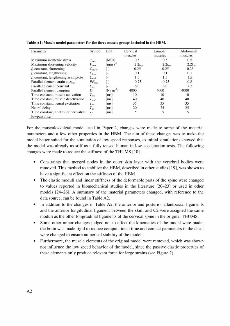
Appendix A: Musculoskeletal Model In the trunk and neck musculoskeletal model used in Paper 2, muscle implementation was based on descriptions from anatomical studies in the literature [1–8] and on implementation in other HBMs [9, 10]. The musculoskeletal model includes the paravertebral muscles of the lumbar and cervical spine, the superficial muscles of the neck, and the abdominal muscles. Muscles that are not included in the model are: the psoas major, the contribution of which to lumbar flexion is negligible [11]; the hyoid muscles of the neck due, to the difficulty of prescribing a correct line of action with only line elements; and the superficial muscles of the back, such as latissimus dorsi and rhomboideus, which mainly contribute to motion of the upper extremities. The skeletal structure of the model was the FE HBM THUMS [10]. The number of elements for each muscle, their origin and insertion points, and the Physiological Cross-Sectional Area (PCSA) of each individual muscle element can be found in Table A3. The PCSA values are taken from dissection studies [1, 3, 7, 12], other HBM studies [9, 13] or those using imaging techniques [14]. For a few muscle elements the curved line of action cannot be represented by a single line element from origin to insertion. Therefore, the node of origin was moved to another location, to give a more biofidelic line of action. The muscles were modeled using the approach described in Paper 1, with the parameters found in Table A1. The maximum isometric stress for all the muscles included in the model were based on the suggestion by Winters and Stark [15], which is a value also used in other HBM studies [13]. The deep muscles of the back consist to a large extent of slow twitch fibers [16], which is why the relation given by Winters and Stark [15] for the maximum shortening velocity gives a value below 5lopt. The value used in the model is half of this value, based on the discussion about muscle element length when tendons are excluded (Paper 1). The constant for fv, Cleng, is chosen so that a smooth transition between eccentric and concentric shortening is achieved. The Cmvl and Cshort are assigned values, used by van der Horst [9], which are also close to those found for the elbow muscles (Paper 1). The PEmax and Cpe are based on curve fits of the passive elastic stiffness reported by Yamada [17]. Data for the rectus abdominis was used for the abdominal muscles and data for the sternocleidomastoid for the rest of the muscles included. Parallel element damping, D, was assigned the value given in Paper 1. The activation dynamics constant for all of the muscles was based on the suggestion by Winters and Stark [15], for muscles that control head movements. Neural delays were estimated, keeping in mind the results reported by de Vlugt et al. [18], for the upper extremity muscles. The head and neck muscles were assigned a shorter delay than the lumbar muscles due to their proximity to the brainstem.
A2
Table A1: Muscle model parameters for the three muscle groups included in the HBM.
Parameter Symbol Unit Cervical muscles
Lumbar muscles
Abdominal muscles
Maximum isometric stress σmax [MPa] 0.5 0.5 0.5 Maximum shortening velocity Vmax [mm s-1] 2.2lopt 2.2lopt 2.2lopt fv constant, shortening Cshort [-] 0.25 0.25 0.25 fv constant, lengthening Cleng [-] 0.1 0.1 0.1 fv constant, lengthening asymptote Cmvl [-] 1.5 1.5 1.5 Parallel element strain at σmax PEmax [-] 0.75 0.75 0.8 Parallel element constant Cpe [-] 6.0 6.0 7.2 Parallel element damping D [Ns m-2] 4000 4000 4000 Time constant, muscle activation Tnaa [ms] 10 10 10 Time constant, muscle deactivation Tnad [ms] 40 40 40 Time constant, neural excitation Tne [ms] 35 35 35 Neural delay Tde [ms] 20 25 25 Time constant, controller derivative lowpass filter
Tf [ms] 5 5 5
For the musculoskeletal model used in Paper 2, changes were made to some of the material parameters and a few other properties in the HBM. The aim of these changes was to make the model better suited for the simulation of low speed responses, as initial simulations showed that the model was already as stiff as a fully tensed human in low acceleration tests. The following changes were made to reduce the stiffness of the THUMS [10].
• Constraints that merged nodes in the outer skin layer with the vertebral bodies were removed. This method to stabilize the HBM, described in other studies [19], was shown to have a significant effect on the stiffness of the HBM.
• The elastic moduli and linear stiffness of the deformable parts of the spine were changed to values reported in biomechanical studies in the literature [20–23] or used in other models [24–26]. A summary of the material parameters changed, with reference to the data source, can be found in Table A2.
• In addition to the changes in Table A2, the anterior and posterior atlantoaxial ligaments and the anterior longitudinal ligament between the skull and C2 were assigned the same moduli as the other longitudinal ligaments of the cervical spine in the original THUMS.
• Some other minor changes judged not to affect the kinematics of the model were made; the brain was made rigid to reduce computational time and contact parameters in the chest were changed to ensure numerical stability of the model.
• Furthermore, the muscle elements of the original model were removed, which was shown not influence the low speed behavior of the model, since the passive elastic properties of these elements only produce relevant force for large strains (see Figure 2).

A3
Table A2. Material parameters changed for the HBM in Paper 2. Anatomical names of the parts from the THUMS model [10]. Eng. strain: Engineering strain.
Part Young’s modulus
Linear stiffness Ref.
[MPa] [N/Eng. strain]
Whole HBM
Invertebral discs, annulus fibrosus 3.4 [20]
Skin, outer shell layer 1.0 [21]
Cervical spine
Ligamentum flavum 3.0 [22]
Ligamentum nuchae 3.0 [24]
Intertransversal ligaments 5.0 [22]
Joint capsules 5.0 [22]
Anterior atlantooccipital membrane 1.5 [23]
Posterior atlantooccipital membrane 3.8 [23]
Alar ligament 9.2 [23]
Cruciform ligament of the atlas 6.0 [25]
Thoracic and lumbar spine
Anterior longitudinal ligament 497 [26]
Posterior longitudinal ligament 200 [26]
Ligamentum flavum 600 [26]
Joint capsules 225 [26]
Supraspinous ligament 300 [26]
Interspinous ligament 240 [26]
A4
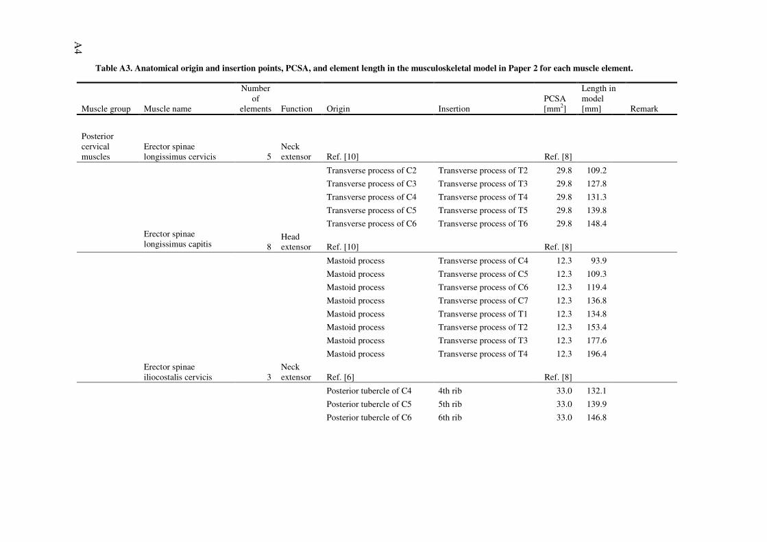
Table A3. Anatomical origin and insertion points, PCSA, and element length in the musculoskeletal model in Paper 2 for each muscle element.
Muscle group Muscle name
Number of
elements Function Origin Insertion PCSA [mm2]
Length in model [mm] Remark
Posterior cervical muscles
Erector spinae longissimus cervicis 5
Neck extensor Ref. [10] Ref. [8]
Transverse process of C2 Transverse process of T2 29.8 109.2
Transverse process of C3 Transverse process of T3 29.8 127.8
Transverse process of C4 Transverse process of T4 29.8 131.3
Transverse process of C5 Transverse process of T5 29.8 139.8
Transverse process of C6 Transverse process of T6 29.8 148.4
Erector spinae longissimus capitis 8
Head extensor Ref. [10] Ref. [8]
Mastoid process Transverse process of C4 12.3 93.9 Mastoid process Transverse process of C5 12.3 109.3 Mastoid process Transverse process of C6 12.3 119.4
Mastoid process Transverse process of C7 12.3 136.8
Mastoid process Transverse process of T1 12.3 134.8
Mastoid process Transverse process of T2 12.3 153.4
Mastoid process Transverse process of T3 12.3 177.6
Mastoid process Transverse process of T4 12.3 196.4
Erector spinae iliocostalis cervicis 3
Neck extensor Ref. [6] Ref. [8]
Posterior tubercle of C4 4th rib 33.0 132.1 Posterior tubercle of C5 5th rib 33.0 139.9 Posterior tubercle of C6 6th rib 33.0 146.8

A5
Muscle group Muscle name
Number of
elements Function Origin Insertion PCSA [mm2]
Length in model [mm] Remark
Multifidus cervicis 12 Neck extensor Ref. [1, 6] Ref. [9]
Spinous process of C2 Transverse process of C5 15.0 48.9 Spinous process of C2 Transverse process of C6 15.0 58.4 Spinous process of C3 Transverse process of C6 15.0 42.2 Spinous process of C3 Transverse process of C7 15.0 58.0 Spinous process of C4 Transverse process of C7 15.0 42.7 Spinous process of C4 Transverse process of T1 15.0 49.2 Spinous process of C5 Transverse process of T1 20.0 38.9 Spinous process of C5 Transverse process of T2 20.0 52.2 Spinous process of C6 Transverse process of T2 40.0 41.6 Spinous process of C6 Transverse process of T3 40.0 67.6 Spinous process of C7 Transverse process of T3 110.0 58.8
Spinous process of C7 Transverse process of T4 130.0 75.8
Semispinalis cervicis 4 Neck extensor Ref. [6] Ref. [8]
Spinous process of C2 Transverse process of T1 100.0 80.9 Spinous process of C3 Transverse process of T2 70.0 83.8 Spinous process of C4 Transverse process of T3 70.0 94.3 Spinous process of C5 Transverse process of T4 70.0 99.3
Semispinalis thoracis 2 Neck extensor Ref. [6] Ref. [-]
Spinous process of C6 Transverse process of T5 70.0 109.0 Estimated PCSA
Spinous process of C7 Transverse process of T6 70.0 122.4 Estimated PCSA

A6
Muscle group Muscle name
Number of
elements Function Origin Insertion PCSA [mm2]
Length in model [mm] Remark
Semispinalis capitis 5 Head extensor Ref. [9, 10] Ref. [8]
Occipital bone Superior articular process of C4
110.0 77.1
Occipital bone Superior articular process of C5
110.0 92.8
Occipital bone Superior articular process of C6
110.0 106.0
Occipital bone Superior articular process of C7
110.0 116.5
Occipital bone Transverse process of T3 110.0 166.2
Splenius cervicis 3 Neck extensor Ref. [6] Ref. [8]
Transverse process of C1 Spinous process of T3 48.0 197.6 Transverse process of C2 Spinous process of T4 48.0 212.3 Transverse process of C3 Spinous process of T5 48.0 230.6
Splenius capitis 6 Head extensor Ref. [6] Ref. [8]
Mastoid process Spinous process of C5 52.0 109.5 Mastoid process Spinous process of C6 52.0 120.1 Mastoid process Spinous process of C7 52.0 129.8 Mastoid process Spinous process of T1 52.0 151.4 Mastoid process Spinous process of T2 52.0 172.2 Mastoid process Spinous process of T3 52.0 198.7
Trapezius 3 Head extensor Ref. [8] Ref. [8]
Skull Clavicula 126.0 209.5 Skull Clavicula 126.0 203.3 Skull Clavicula 126.0 197.2

A7
Muscle group Muscle name
Number of
elements Function Origin Insertion PCSA [mm2]
Length in model [mm] Remark
Levator scapulae 4 Neck extensor Ref. [6] Ref. [8]
Transverse process of C1 Scapula 78.0 173.5 Transverse process of C2 Scapula 78.0 164.4 Transverse process of C3 Scapula 78.0 168.1 Transverse process of C4 Scapula 78.0 153.9
Rectus capitis posterior minor 1
Head extensor Ref. [6] Ref. [8]
Occipital bone Posterior tubercle of C1 92.0 36.6
Rectus capitis posterior major 1
Head extensor Ref. [6] Ref. [8]
Occipital bone Spine of C2 168.0 55.1
Rectus capitis anterior 1 Head flexor Ref. [6] Ref. [13]
Skull C1 70.0 25.3
Rectus capitis lateralis 1 Head extensor Ref. [6] Ref. [13]
Skull C1 70.0 24.0
Obliqus capitis superior 1 Head extensor Ref. [6] Ref. [8]
Occipital bone Transverse process of C1 88.0 39.5
Obliqus capitis inferior 1 Neck extensor Ref. [6] Ref. [8]
Transverse process of C1 Spinous process of C2 195.0 49.7
Anterior cervical muscles Scalenus posterior 3
Neck flexor Ref. [6, 10] Ref. [8]
Transverse process of C4 1st rib 35.0 67.5 Transverse process of C5 1st rib 35.0 44.3 Transverse process of C6 1st rib 35.0 24.8

A8
Muscle group Muscle name
Number of
elements Function Origin Insertion PCSA [mm2]
Length in model [mm] Remark
Scalenus medius 6 Neck flexor Ref. [6] Ref. [8]
C2 1st rib 23.0 135.7 C3 1st rib 23.0 129.7 C4 1st rib 23.0 102.7 C5 1st rib 23.0 90.3 C6 1st rib 23.0 64.7 C7 1st rib 23.0 63.2
Scalenus anterior 4 Neck flexor Ref. [10] Ref. [8]
Anterior tubercle of C3 1st rib 47.0 130.7 Anterior tubercle of C4 1st rib 47.0 106.1 Anterior tubercle of C5 1st rib 47.0 87.9 Anterior tubercle of C6 1st rib 47.0 78.9
Longus colli superior oblique 3
Neck flexor Ref. [6] Ref. [13]
Anterior arch of C1 Transverse process of C3 27.0 38.3 Anterior arch of C1 Transverse process of C4 27.0 56.7 Anterior arch of C1 Transverse process of C5 27.0 70.1
Longus colli vertical 4 Neck flexor Ref. [6] Ref. [13]
Vertebral body of C2 Vertebral body of C7 22.5 91.8 Vertebral body of C2 Vertebral body of T1 22.5 112.5 Vertebral body of C3 Vertebral body of T2 22.5 52.1 Vertebral body of C4 Vertebral body of T3 22.5 21.6
Longus colli inferior oblique 2
Neck flexor Ref. [6] Ref. [13]
Transverse process of C5 Vertebral body of T1 20.0 64.9 Transverse process of C6 Vertebral body of T2 20.0 61.7

A9
Muscle group Muscle name
Number of
elements Function Origin Insertion PCSA [mm2]
Length in model [mm] Remark
Longus capitis 4 Head flexor Ref. [6, 10] Ref. [8]
Occipital bone Transverse process of C3 34.0 59.7 Occipital bone Transverse process of C4 34.0 74.4 Occipital bone Transverse process of C5 34.0 95.3 Occipital bone Transverse process of C6 34.0 109.0
Sternocleidomastoid 2 Head flexor Ref. [6, 10] Ref. [8]
Mastoid process Clavicula 246.0 169.2 Mastoid process Sternum 246.0 205.6
Lumbar muscles Quadratus lumborum 5
Lumbar extensor Ref. [2] Ref. [12]
12th rib Iliac crest 80.0 143.2 Transverse process of L1 Iliac crest 80.0 125.0 Transverse process of L2 Iliac crest 40.0 93.4 Transverse process of L3 Iliac crest 40.0 61.8 Transverse process of L4 Iliac crest 40.0 43.8
Multifidus thoracis 8 Lumbar extensor Ref. [4, 6] Ref. [14]
Spinous process of T8 Transverse process of L1 25.0 121.9 Spinous process of T9 Transverse process of L1 45.0 97.7 Spinous process of T10 Transverse process of L1 39.0 63.5 Spinous process of T10 Transverse process of L2 65.0 102.8 Spinous process of T11 Transverse process of L2 29.0 79.0 Spinous process of T11 Transverse process of L3 90.0 114.6 Spinous process of T12 Transverse process of L3 53.0 80.7 Spinous process of T12 Transverse process of L4 118.0 117.7

A10
Muscle group Muscle name
Number of
elements Function Origin Insertion PCSA [mm2]
Length in model [mm] Remark
Multifidus lumborum 13 Lumbar extensor Ref. [3, 4, 5] Ref. [3]
Spinous process of L1 Mamillary process of L4 40.0 79.1 Spinous process of L1 Mamillary process of L5 42.0 105.6 Spinous process of L1 Sacrum 36.0 139.3 Spinous process of L1 Iliac crest 60.0 157.8 Spinous process of L2 Mamillary process of L5 39.0 73.0 Spinous process of L2 Sacrum 39.0 109.0 Spinous process of L2 Iliac crest 90.0 136.9 Spinous process of L3 Sacrum 54.0 69.9 Spinous process of L3 Iliac crest 157.0 141.1 Spinous process of L4 Sacrum 93.0 82.9 Spinous process of L4 Iliac crest 93.0 101.1 Spinous process of L5 Sacrum 45.0 63.8 Spinous process of L5 Iliac crest 45.0 79.0

A11
Muscle group Muscle name
Number of
elements Function Origin Insertion PCSA [mm2]
Length in model [mm] Remark
Erector spinae longissimus thoracis pars thoracis 12
Lumbar extensor Ref. [3] Ref. [3]
7th rib Spinous process of L2 29.0 219.6 Anatomical origin 1st rib.
8th rib Spinous process of L2 57.0 196.1 Anatomical origin 2nd rib.
8th rib Spinous process of L3 56.0 236.2 Anatomical origin 3rd rib.
9th rib Spinous process of L4 45.0 263.9 Anatomical origin 4th rib.
9th rib Spinous process of L4 44.0 267.1 Anatomical origin 5th rib.
9th rib Spinous process of L5 64.0 262.6 Anatomical origin 6th rib.
10th rib Sacrum 78.0 267.9 Anatomical origin 7th rib.
11th rib Sacrum 125.0 250.2 Anatomical origin 8th rib.
11th rib Sacrum 146.0 270.2 Anatomical origin 9th rib.
11th rib Sacrum 160.0 269.0 Anatomical origin 10th rib.
11th rib Sacrum 167.0 265.7
12th rib Sacrum 138.0 229.6
Erector spinae longissimus thoracis pars lumborum 5
Lumbar extensor Ref. [3] Ref. [3]
Transverse process of L1 Iliac crest 79.0 150.6 Transverse process of L2 Iliac crest 91.0 110.3 Transverse process of L3 Iliac crest 103.0 68.6 Transverse process of L4 Iliac crest 110.0 42.7
Transverse process of L5 Iliac crest 116.0 31.2

A12
Muscle group Muscle name
Number of
elements Function Origin Insertion PCSA [mm2]
Length in model [mm] Remark
Erector spinae iliocostalis lumborum pars thoracis 8
Lumbar extensor Ref. [3] Ref. [3]
12th rib Iliac crest 23.0 197.4 Anatomical origin 5th rib.
12th rib Iliac crest 31.0 175.6 Anatomical origin 6th rib.
12th rib Iliac crest 39.0 161.3 Anatomical origin 7th rib.
12th rib Iliac crest 34.0 155.4 Anatomical origin 8th rib.
12th rib Iliac crest 50.0 134.8 Anatomical origin 9th rib.
12th rib Iliac crest 100.0 141.1 Anatomical origin 10th rib.
12th rib Iliac crest 123.0 136.4 Anatomical origin 11th rib.
12th rib Iliac crest 147.0 143.5
Erector spinae iliocostalis lumborum pars lumborum 4
Lumbar extensor Ref. [3] Ref. [3]
Transverse process of L1 Iliac crest 108.0 150.7 Transverse process of L2 Iliac crest 154.0 106.1 Transverse process of L3 Iliac crest 182.0 63.3 Transverse process of L4 Iliac crest 189.0 42.2

A13
Muscle group Muscle name
Number of
elements Function Origin Insertion PCSA [mm2]
Length in model [mm] Remark
Abdominal muscles Rectus abdominis 3
Lumbar flexor Ref. [6, 7] Ref. [7]
5th costal cartilage Crest of pubis 189.0 260.8
6th costal cartilage Crest of pubis 189.0 232.5 7th costal cartilage Crest of pubis 189.0 210.7
Internal oblique 2 Lumbar flexor Ref. [6, 7] Ref. [7]
Costal cartilage Iliac crest 354.9 108.2 Costal cartilage Iliac crest 354.9 120.9
External oblique 2 Lumbar flexor Ref. [6, 7] Ref. [7]
Costal cartilage Iliac crest 452.4 137.9 Costal cartilage Iliac crest 452.4 143.2

A14
Muscle Geometry
Figure A1. Front view of all muscles implemented
Figure A3. Erector spinae longissimus cervicis
. Front view of all muscles implemented. Figure A2. Rear view of all
Figure A4. Erector spinae longissimus capitis
Figure Ailiocostalis cervicis
. Rear view of all muscles implemented.
Figure A5. Erector spinae iliocostalis cervicis

Figure A6. Multifidus cervicis
Figure A9. Semispinalis capitis
Figure A12. Trapezius
Figure A7. Semispinalis cervicis Figure A
Figure A10. Splenius cervicis Figure A
Figure A13. Levator scapulae Figure Aposterior minor
A15
Figure A8. Semispinalis thoracis
Figure A11. Splenius capitis
Figure A14. Rectus capitis posterior minor

A16
Figure A15. Rectus capitis posterior major
Figure A18. Scalenus posterior
Figure A21. Longus colli superior oblique
Figure A16. Obliqus capitis superior and inferior
Figure Aanterior and lateralis
Figure A19. Scalenus medius Figure A
. Longus colli superior Figure A22. Longus colli vertical Figure Aoblique
Figure A17. Rectus capitis anterior and lateralis
Figure A20. Scalenus anterior
Figure A23. Longus colli inferior

Figure A24. Longus capitis
Figure A26. Quadratus lumborum
Figure A29. Erector spinae longissimus thoracis pars thoracis
Figure A25. Sternocleidomastoid
. Quadratus lumborum Figure A27. Multifidus thoracis Figure A
longissimus thoracis pars thoracis Figure A30. Erector spinae longissimus thoracis pars lumborum
Figure Ailiocostalis lumborum pars thoracis
A17
Figure A28. Multifidus lumborum
Figure A31. Erector spinae iliocostalis lumborum pars
A18
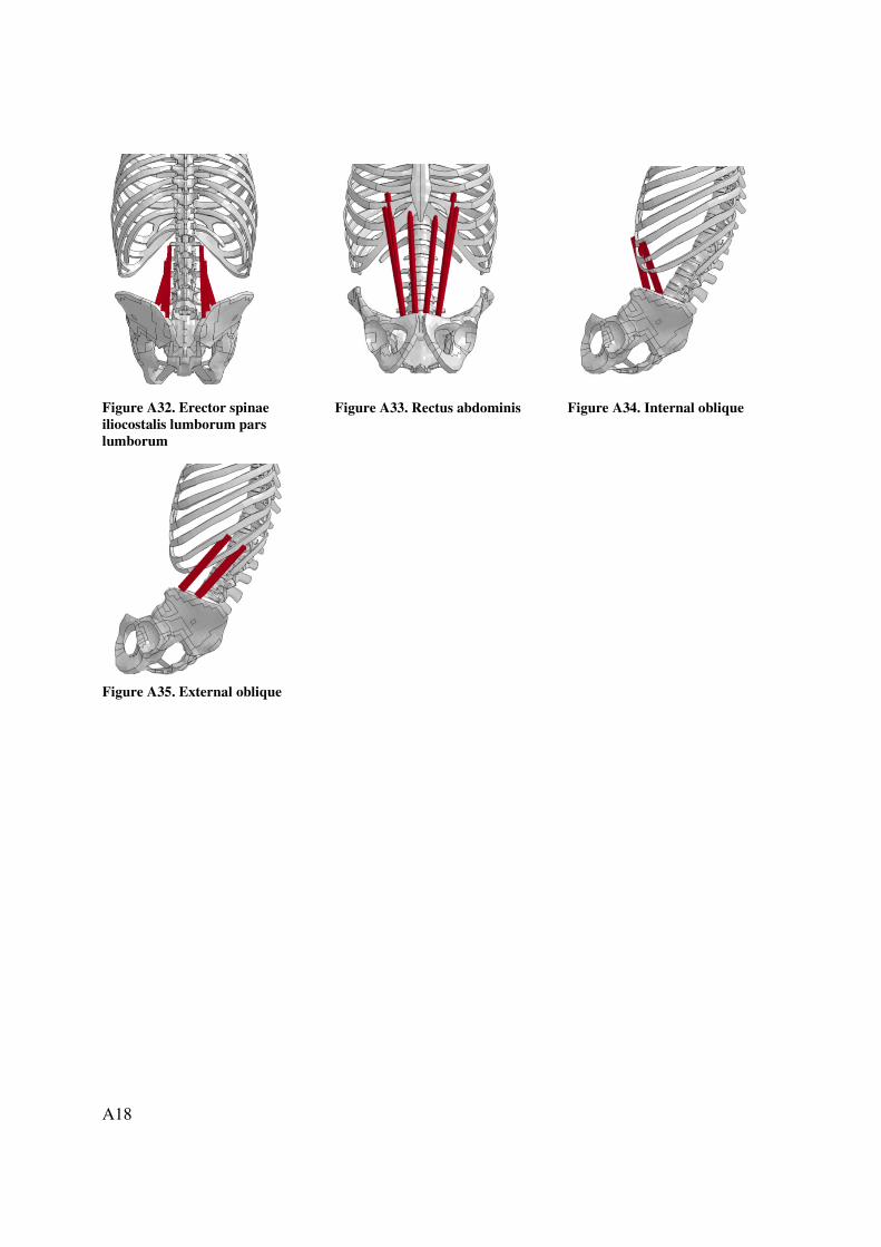
Figure A32. Erector spinae iliocostalis lumborum pars lumborum
Figure A35. External oblique
Figure A33. Rectus abdominis Figure A
Figure A34. Internal oblique
A19
References [1] Anderson JS, Hsu AW, Vasavada AN. 2005. Morphology, Architecture, and
Biomechanics of Human Cervical Multifidus. Spine. 30(4):E86–91. [2] Bogduk N, Endres SM. 2005. Clinical Anatomy of the Lumbar Spine and Sacrum.
London, Elsevier Churchill Livingstone. [3] Bogduk N, Macintosh JE, Pearcy MJ. 1992. A universal model of the lumbar back
muscles in the upright position. Spine. 17(8):897–913. [4] Macintosh JE, Bogduk N. 1986. The biomechanics of the lumbar multifidus. Clin.
Biomech. 1:205–213. [5] Macintosh JE, Valencia F, Bogduk N, Munro RR. 1986. The morphology of the human
lumbar multifidus. Clin. Biomech. 1:196–204. [6] Standring S., editor. 2008. Gray’s Anatomy – The anatomical basis of clinical practice.
London, Elsevier Churchill Livingstone. [7] Stokes IAF, Gardner–Morse M. 1999. Quantitative anatomy of the lumbar musculature. J.
Biomech. 32:311–316. [8] Van Ee CA, Nightingale RW. Camacho DLA, Chancey VC, Knaub KE, Sun EA, Myers
BS. 2000. Tensile Properties of the Human Muscular and Ligamentous Cervical Spine. Stapp Car Crash J. 44, 2000–01–SC10.
[9] van der Horst M. 2002. Human Head Neck Response in Frontal, Lateral and Rear End Impact Loading – Modeling and Validation. [PhD Thesis]. [Eindhoven, Netherlands]: Eindhoven University of Technology.
[10] Toyota Motor Corporation, Toyota Central Labs Inc. 2008. Users' Guide of Computational Human Model THUMS® – AM50 Occupant Model: Version 3.0–080225.
[11] Bogduk N, Pearcy M, Hadfield G. 1992. Anatomy and biomechanics of psoas major. Clin. Biomech. 7:109–119.
[12] Delp SL, Suryanarayanan S, Murray WM, Uhlir J, Triolo RJ. 2001. Architecture of the rectus abdominis, quadratus lumborum, and erector spinae. J. Biomech. 34:371–375.
[13] Hedenstierna S. 2008. 3D Finite Element Modeling of Cervical Musculature and its Effect on Neck Injury Prevention. [PhD Thesis]. [Stockholm, Sweden]: Royal Institute of Technology.
[14] Daggfelt K, Thorstensson A. 2003. The mechanics of back–extensor torque production about the lumbar spine. J. Biomech. 36:815–825.
[15] Winters JM, Stark L. 1988. Estimated mechanical properties of synergistic muscles involved in movements of a variety of human joints. J. Biomech. 21(12):1027–1041.
[16] Jörgenssen K, Nicholaisen T, Kato M. 1993. Muscle Fiber Distribution, Capillary Density, and Ensymatic Activities in the Lumbar Paravertebral Muscles of Young Men. Spine. 18(11):1439–1450.
[17] Yamada H. 1970. Strength of Biological Materials. Baltimore (MD): Williams & Wilkins. [18] de Vlugt E, Schouten AC, van der Helm FCT. 2006. Quantification of intrinsic and
reflexive properties during multijoint arm posture. J. Neurosci. Methods 155:328–349. [19] Kimpara H, Nakahira Y, Iwamoto M, Kazuo M, Ichihara K, Kawano Shun-ichi, Taguchi
T. 2006. Investigation of Anteroposterior Head-Neck Responses during Severe Frontal Impacts Using a Brain-Spinal Cord Complex FE Model. Stapp Car Crash J. 50:509–544.

A20
[20] Yoganandan N, Kumaresan S, Pintar FA. 2001. Biomechanics of the cervical spine Part 2. Cervical spine soft tissue responses and biomechanical modeling. Clin. Biomech. 16:1–27.
[21] Diridillou S, Black D, Lagarde JM, Gall Y, Berson M, Vabre V, Patat F, Valliant L. 2000. Sex- and site-dependent variations in the thickness and mechanical properties of human skin in vivo. Int. J. Cosmetic Sci. 22:421–435.
[22] Yoganandan N, Kumaresan S, Pintar F. 2000. Geometric and Mechanical Properties of Human Cervical Spine Ligaments. J. Biomech. Eng. 122:623–629.
[23] Myklebust JB, Pintar F, Yoganadan N, Cusick JF, Maiman D, Myers TJ, Sances Jr. A. 1988.Tensile Strength of Spinal Ligaments. Spine. 13(5):526–531.
[24] Maurel N, Lavaste F, Skalli W. 1998. A Three-dimensional Parameterized Finite Element Model of the Lower Cervical Spine. Study of the Influence of the Posterior Articular Facets. J. Biomech. 30:921–931.
[25] Brolin K, Halldin P. 2004. Development of a Finite Element Model of the Upper Cervical Spine and a Parameter Study of Ligament Characteristics. Spine. 29(4): 376–385.
[26] Pitzen T, Geisler F, Matthis D, Müller-Storz, Barbier D, Steudel W-I, Feldges A. 2002. A finite element model for predicting the biomechanical behaviour of the human lumbar spine. Control Eng. Pract. 10:83–90.
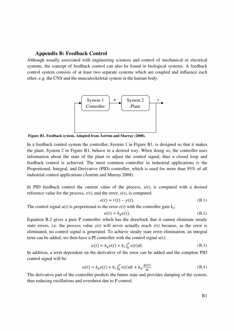
B1
Appendix B: Feedback Control Although usually associated with engineering sciences and control of mechanical or electrical systems, the concept of feedback control can also be found in biological systems. A feedback control system consists of at least two separate systems which are coupled and influence each other, e.g. the CNS and the musculoskeletal system in the human body.
Figure B1. Feedback system. Adapted from Åström and Murray (2008).
In a feedback control system the controller, System 1 in Figure B1, is designed so that it makes the plant, System 2 in Figure B1, behave in a desired way. When doing so, the controller uses information about the state of the plant to adjust the control signal; thus a closed loop and feedback control is achieved. The most common controller in industrial applications is the Proportional, Integral, and Derivative (PID) controller, which is used for more than 95% of all industrial control applications (Åström and Murray 2008). In PID feedback control the current value of the process, y(t), is compared with a desired reference value for the process, r(t), and the error, e(t), is computed: ���� � ���� � ����. (B.1 )
The control signal u(t) is proportional to the error e(t) with the controller gain kp: ��� � �����. (B.2 )
Equation B.2 gives a pure P controller which has the drawback that it cannot eliminate steady state errors, i.e. the process value y(t) will never actually reach r(t) because, as the error is eliminated, no control signal is generated. To achieve steady state error elimination, an integral term can be added; we then have a PI controller with the control signal u(t): ��� � ����� � � ������
�
�. (B.3 )
In addition, a term dependent on the derivative of the error can be added and the complete PID control signal will be:
��� � ����� � � �������
�� �
�����
��. (B.4 )
The derivative part of the controller predicts the future state and provides damping of the system, thus reducing oscillations and overshoot due to P control.
y u System 1 Controller
System 2 Plant

B2
Consider the simple spring-damper system, shown in Figure B2, which is under the influence of the control signal, u(t), generated according to Equations B.1 to B.4. The response of the system to a unit step reference signal, r(t), at time t = 0.1 can be seen in Figure B3.
Figure B2. Spring–damper system with control signal u(t).
The proportional controller gives a quick response, but with a large overshoot and oscillatory behavior before the system enters a steady state. The addition of the derivative part dampens the overshoot and oscillations, while adding integral control eliminates the steady state error. The proportional gain, kp, is usually the most important component of the PID control; to a large extent it influences the response time of the system, which decreases for an increasing proportional gain. However, as can be seen in Figure B3, the proportional gain can also induce oscillations into the system and, for high gains; it can also make the system unstable. Therefore, there is a tradeoff between system performance and stability, and the determination of system stability is central to many studies of control systems.
Figure B3. Spring–damper feedback system response to unit step reference signal (thin solid line) at t = 0.1 with P (solid thick line), PD (dashed line), and PID control (dotted line).
y(t)
cy(t) ky(t)
u(t)
M
•


![Authors’ Responseonline.sfsu.edu/morsella/images/AuthorReply.pdf · [parallel responses into skeletal muscle]), PFT yields novel insights. For example, our approach specifies how,](https://img.pdfslide.net/doc/110x75/603ce2ca6308415eba0a14fa/authorsa-parallel-responses-into-skeletal-muscle-pft-yields-novel-insights.jpg)


![RESEARCH ARTICLE Open Access Changes of direction …bolic responses to straight-line HIE is improving (e.g., cardiorespiratory [13], muscle tissue oxygenation [14] responses), little](https://img.pdfslide.net/doc/110x75/5f0510f17e708231d4111728/research-article-open-access-changes-of-direction-bolic-responses-to-straight-line.jpg)