Embed Size (px)
Citation preview

Actuator control using pre-calibrated force
data on a quadrocopter
Amil LahMaster thesis in Robotics (30 ECTS credits)
Mälardalens University, IDTSupervisor. Giacomo SpampinatotextitExaminer. Lars Asplund
August 21, 2013

Abstract
In ying robots, stability control is often very sensitive to the actuator performances, andthe software module performing the controller, is usually subjected to a long and diculttuning phase strongly dependent on the specic actuator used. The actuators are oftenelectric motors equipped with propellers. The motor and propeller combination performsdierently for every choice of components adopted, even if they are provided by the samevendor with the same part family. The project aims to develop an intelligent actuatormodule for ying robots composed by a BLDC motor and a propeller, which is invariantto the specic motor and propeller adopted.
By gathering the force data of the four used on a quadrocopter, the force and control-signal relation could be dened and stored into the program memory of Arduino. Abattery monitor and a force-pwm controller was implemented such that it takes force asinput and outputs the desired PWM-signal. Tests were made on a prototype of Iqarusquadrocopter and by mounting it with ropes to the oor, it was tested on the lift-ophase. The experiment showed theoretical and practical results, which concludes that thequadrocopter maintained the ability to lift right upwards without any remaining control,assuming proper weight balance of the quadrocopter.

Abstrakt
Inom ygande robotar, är stabilitet kontrollen oerhört känsligt till styrdonets prestation,och mjukvaru modulen som utför kontrollen, är ofta förknippad med en lång och problema-tisk justerings fas starkt beroende av de enskilda styrdonen. Styrdonen är ofta elektriskamotorer med propeller. Motor och propeller kombinationen uppträder olika för varje valav komponent, även om komponenterna är försedda från samma återförsäljare och modell.Syftet med detta projekt är att utveckla en intelligent styrdons modul för ygande robotar,omfattad av en BLDC motor och propeller, som blir oberoende av den särskilda motor ochpropeller kombination som används.
Genom att samla kraft data för de fyra styrdonen som används på en quadrocopter,kunde relationen mellan kraft och kontroll-signal bli denierat och lagrat i program minnet.En batteri monitor och en kraft-pwm kontroller implementerades, vilket tar kraft datasom ingång och skickar ut motsvarande PWM-signal som utgång. Tester var gjorda meden prototyp av Iqarus quadrocopter och genom att binda fast den med rep till golvet,testades den för upplyfts fasen. Experimenten visade teoretiska och praktiska resultat,vilket visar att quadrocoptern bevarade förmågan att lyfta rakt uppåt utan någon övrigkontroll, förutsatt ordentlig vikt balans av quadrocoptern.

Acknowledgements
I would like to thank Giacomo Spampinato, which came up with this interesting projectidea and oered the supervisor position for my thesis. It also gave me the chance to con-tinue developing the quadrocopter, which me and 13 other students from the Roboticprogram worked together with. A big thank to the rest of the project group which suc-cessfully managed to construct and run a quadrocopter, and thanks to Mikael Åsberg andFredrik Ekstrand for guidelines throughout the Iqarus project and for letting me to usethe prototype of Iqarus quadrocopter.
I would also like to thank Ivica Crnkovic, for giving me the signicant opportunity towork on this thesis during my exchange period in UFBA (Federal University of Brazil) inSalvador. And thanks to Eduardo Almeida for being my supervisor during the residencein UFBA, and for providing me with everything I needed for working with my thesis.

Contents
List of Figures 3
1 Introduction 51.1 Background . . . . . . . . . . . . . . . . . . . . . . . . . . . . . . . . . . . . 51.2 Contribution . . . . . . . . . . . . . . . . . . . . . . . . . . . . . . . . . . . 61.3 Motivation . . . . . . . . . . . . . . . . . . . . . . . . . . . . . . . . . . . . . 61.4 Outline . . . . . . . . . . . . . . . . . . . . . . . . . . . . . . . . . . . . . . 7
2 Background 82.1 Hardware components of the actuator line . . . . . . . . . . . . . . . . . . . 8
2.1.1 Motors . . . . . . . . . . . . . . . . . . . . . . . . . . . . . . . . . . . 82.1.2 Lipo battery . . . . . . . . . . . . . . . . . . . . . . . . . . . . . . . 102.1.3 ESC . . . . . . . . . . . . . . . . . . . . . . . . . . . . . . . . . . . . 11
2.2 Control of Iqarus quadrocopter . . . . . . . . . . . . . . . . . . . . . . . . . 122.2.1 Stabilisation . . . . . . . . . . . . . . . . . . . . . . . . . . . . . . . . 122.2.2 Navigation . . . . . . . . . . . . . . . . . . . . . . . . . . . . . . . . 132.2.3 RPM measurement . . . . . . . . . . . . . . . . . . . . . . . . . . . . 14
3 State of the Art 153.1 Related works . . . . . . . . . . . . . . . . . . . . . . . . . . . . . . . . . . . 153.2 Summary . . . . . . . . . . . . . . . . . . . . . . . . . . . . . . . . . . . . . 18
4 Problem Statement 194.1 Problem to be solved . . . . . . . . . . . . . . . . . . . . . . . . . . . . . . . 194.2 Project description . . . . . . . . . . . . . . . . . . . . . . . . . . . . . . . . 194.3 Choice and specication of components . . . . . . . . . . . . . . . . . . . . . 20
4.3.1 Arduino Mega2560 vs. Arduino Due . . . . . . . . . . . . . . . . . . 204.3.2 Force sensor . . . . . . . . . . . . . . . . . . . . . . . . . . . . . . . . 214.3.3 Actuator line . . . . . . . . . . . . . . . . . . . . . . . . . . . . . . . 22
4.4 Summary . . . . . . . . . . . . . . . . . . . . . . . . . . . . . . . . . . . . . 23
5 Hardware Process 245.1 Force sensor . . . . . . . . . . . . . . . . . . . . . . . . . . . . . . . . . . . . 24
5.1.1 Mechanical construction . . . . . . . . . . . . . . . . . . . . . . . . . 245.1.2 Circuit construction . . . . . . . . . . . . . . . . . . . . . . . . . . . 255.1.3 Calibrate the circuit to achieve the force . . . . . . . . . . . . . . . . 265.1.4 LP-lter and EMI rejection . . . . . . . . . . . . . . . . . . . . . . . 285.1.5 Gather data from the load cell . . . . . . . . . . . . . . . . . . . . . 28
5.2 Battery monitor . . . . . . . . . . . . . . . . . . . . . . . . . . . . . . . . . . 305.2.1 Voltage divider . . . . . . . . . . . . . . . . . . . . . . . . . . . . . . 305.2.2 Voltage divider bias of a BJT transistor . . . . . . . . . . . . . . . . 32
5.3 Summary . . . . . . . . . . . . . . . . . . . . . . . . . . . . . . . . . . . . . 33
1

6 Software method 346.1 Read analog inputs from Arduino . . . . . . . . . . . . . . . . . . . . . . . . 346.2 Compensate for the battery monitor . . . . . . . . . . . . . . . . . . . . . . 356.3 Force curve adjustment . . . . . . . . . . . . . . . . . . . . . . . . . . . . . . 366.4 Gather and store data in Arduino . . . . . . . . . . . . . . . . . . . . . . . . 376.5 Force-PWM controller . . . . . . . . . . . . . . . . . . . . . . . . . . . . . . 406.6 Summary . . . . . . . . . . . . . . . . . . . . . . . . . . . . . . . . . . . . . 41
7 Experiments 427.1 Force eect over time . . . . . . . . . . . . . . . . . . . . . . . . . . . . . . . 427.2 Compare motor and propeller . . . . . . . . . . . . . . . . . . . . . . . . . . 437.3 Testing the software . . . . . . . . . . . . . . . . . . . . . . . . . . . . . . . 447.4 Testing the lift-o phase . . . . . . . . . . . . . . . . . . . . . . . . . . . . . 477.5 Summary . . . . . . . . . . . . . . . . . . . . . . . . . . . . . . . . . . . . . 47
8 Analysing the Results 48
9 Summary and Conclusion 49
10 Discussion and Future Work 5110.1 Discussion . . . . . . . . . . . . . . . . . . . . . . . . . . . . . . . . . . . . . 5110.2 Future work . . . . . . . . . . . . . . . . . . . . . . . . . . . . . . . . . . . . 51
Bibliography 53
Glossary 54
A INA125P Datasheet 55
B Vetek Single Point Load cell 56
C T-motor KV1100 Datasheet 57
D T-motor KV900 58
E Arduino Mega2560 Rev3 Schematic 59
F ATMEL Mega2560 Datasheet 60
G Software: Gather and Store 61G.1 Main function . . . . . . . . . . . . . . . . . . . . . . . . . . . . . . . . . . . 61G.2 Filter functions . . . . . . . . . . . . . . . . . . . . . . . . . . . . . . . . . . 64G.3 Write to EEPROM functions . . . . . . . . . . . . . . . . . . . . . . . . . . 66
H Software: Read and Run 68H.1 Main function . . . . . . . . . . . . . . . . . . . . . . . . . . . . . . . . . . . 68H.2 Read from EEPROM function . . . . . . . . . . . . . . . . . . . . . . . . . . 69H.3 Force-PWM Controller . . . . . . . . . . . . . . . . . . . . . . . . . . . . . . 70
2

List of Figures
1.1 Iqarus quadrocopter . . . . . . . . . . . . . . . . . . . . . . . . . . . . . . . 5
2.1 T-motor KV1100 . . . . . . . . . . . . . . . . . . . . . . . . . . . . . . . . . 82.2 Unmounted BLDC Outrunner motor . . . . . . . . . . . . . . . . . . . . . . 92.3 Sequence pattern of a 3-phase motor . . . . . . . . . . . . . . . . . . . . . . 92.4 Motor variation between two BLDC motors . . . . . . . . . . . . . . . . . . 92.5 APC propeller 9x4.7 . . . . . . . . . . . . . . . . . . . . . . . . . . . . . . . 102.6 Lipo battery Tripple 3S 3000mAh . . . . . . . . . . . . . . . . . . . . . . . . 102.7 Hobbywing Flyfun 18-A . . . . . . . . . . . . . . . . . . . . . . . . . . . . . 112.8 Roll and pitch eect on the quadrocopter . . . . . . . . . . . . . . . . . . . 122.9 Constants eect on PID-controller . . . . . . . . . . . . . . . . . . . . . . . 132.10 Movement commands on the quadrocopter . . . . . . . . . . . . . . . . . . . 13
3.1 Test bench using a digital weight scale . . . . . . . . . . . . . . . . . . . . . 153.2 Another test bench using a digital weight scale . . . . . . . . . . . . . . . . 153.3 Thrust data of four motors (Sikiric's) . . . . . . . . . . . . . . . . . . . . . . 163.4 Hobby Prop Balancer . . . . . . . . . . . . . . . . . . . . . . . . . . . . . . . 173.5 Hover thrust vs. Battery voltage . . . . . . . . . . . . . . . . . . . . . . . . 17
4.1 The problems are going to be solved . . . . . . . . . . . . . . . . . . . . . . 194.2 Vetek Single Point Load cell . . . . . . . . . . . . . . . . . . . . . . . . . . . 194.3 Gather data before run-time . . . . . . . . . . . . . . . . . . . . . . . . . . . 204.4 Process the data under run-time . . . . . . . . . . . . . . . . . . . . . . . . 204.5 Load cell construction and strain gauges . . . . . . . . . . . . . . . . . . . . 214.6 Wheatstone bridge circuit . . . . . . . . . . . . . . . . . . . . . . . . . . . . 22
5.1 Pressure applied to load cell . . . . . . . . . . . . . . . . . . . . . . . . . . . 245.2 Plates placed on load cell . . . . . . . . . . . . . . . . . . . . . . . . . . . . 245.3 Final mechanical construction . . . . . . . . . . . . . . . . . . . . . . . . . . 245.4 Suggested circuits for INA125P . . . . . . . . . . . . . . . . . . . . . . . . . 255.5 Resistor values to specify the gain . . . . . . . . . . . . . . . . . . . . . . . . 255.6 Final circuit for INA125P . . . . . . . . . . . . . . . . . . . . . . . . . . . . 265.7 Dierent gain value settings . . . . . . . . . . . . . . . . . . . . . . . . . . . 265.8 Oset resistor set in four dierent ways . . . . . . . . . . . . . . . . . . . . . 275.9 Equation found in Excel . . . . . . . . . . . . . . . . . . . . . . . . . . . . . 275.10 LP-lters and software delay timings . . . . . . . . . . . . . . . . . . . . . . 285.11 PS and Lipo dierence on force output . . . . . . . . . . . . . . . . . . . . . 295.12 Force output of dierent PS voltages . . . . . . . . . . . . . . . . . . . . . . 295.13 Voltage divider with high and low resistance . . . . . . . . . . . . . . . . . . 315.14 Final voltage divider circuit . . . . . . . . . . . . . . . . . . . . . . . . . . . 315.15 Comparison with using a LP-lter . . . . . . . . . . . . . . . . . . . . . . . 315.16 Comparision of battery monitor using PS and Lipo battery . . . . . . . . . 325.17 BJT Transistor circuit . . . . . . . . . . . . . . . . . . . . . . . . . . . . . . 325.18 BJT Transistor circuit with corresponding values . . . . . . . . . . . . . . . 335.19 Simple voltage divider vs. BJT Transistor . . . . . . . . . . . . . . . . . . . 33
6.1 Battery voltage drop . . . . . . . . . . . . . . . . . . . . . . . . . . . . . . . 35
3
6.2 Battery voltage compensation . . . . . . . . . . . . . . . . . . . . . . . . . . 356.3 Battery voltage compensation with oset values . . . . . . . . . . . . . . . . 366.4 Force curve adjustment opt. 2.1 . . . . . . . . . . . . . . . . . . . . . . . . . 366.5 Force curve adjustment opt. 2.3 . . . . . . . . . . . . . . . . . . . . . . . . . 376.6 Force curve adjustment opt. 3 . . . . . . . . . . . . . . . . . . . . . . . . . . 376.7 Interesting area of force data . . . . . . . . . . . . . . . . . . . . . . . . . . 386.8 Program ow for Gather and Store . . . . . . . . . . . . . . . . . . . . . . . 396.9 Program ow for battery compensation . . . . . . . . . . . . . . . . . . . . . 40
7.1 Current to force relation . . . . . . . . . . . . . . . . . . . . . . . . . . . . . 427.2 Current and force over time . . . . . . . . . . . . . . . . . . . . . . . . . . . 427.3 Force line at 400g and 300g over time . . . . . . . . . . . . . . . . . . . . . . 437.4 Dierence between two motors . . . . . . . . . . . . . . . . . . . . . . . . . 437.5 Dierence between two motors and three propellers . . . . . . . . . . . . . . 447.6 Four rst force curves to be stored . . . . . . . . . . . . . . . . . . . . . . . 447.7 Filtered force curve vs. Original . . . . . . . . . . . . . . . . . . . . . . . . . 457.8 Resulting battery voltage (red line) . . . . . . . . . . . . . . . . . . . . . . . 457.9 Resulting battery voltage (red line) under run-time . . . . . . . . . . . . . . 457.10 First, second and estimated force curve . . . . . . . . . . . . . . . . . . . . . 457.11 Four motors with 1st and 2nd force curves . . . . . . . . . . . . . . . . . . . 467.12 The four desired PWM-signals . . . . . . . . . . . . . . . . . . . . . . . . . 467.13 Quadrocopter mounted to the oor . . . . . . . . . . . . . . . . . . . . . . . 47
8.1 Force of 200-300g at 13.10V . . . . . . . . . . . . . . . . . . . . . . . . . . . 488.2 Force of 200-300g at 11.35V . . . . . . . . . . . . . . . . . . . . . . . . . . . 48
4

1 | Introduction
1.1 Background
This project is currently based on the quadrocopter project named Iqarus, which wasdeveloped in a project course in Mälardalens University by 13 Master students. Themain goal of the project was to have 4-5 autonomous quadrocopters with one leader inthe front, following each other like a train. By communicate via bluetooth and perceivethe environment using Computer-Vision system through a camera, the quadrocopters canshare information among each other. The concept can be used in several applications,while the main goal is to be used in search- and rescue missions. This thesis aims todevelop the controller for the actuators (motor and propeller) used on the quadrocopter,which is to investigate the control of the specic motor and propeller combination used.The performance of the actuators depends on other hardware components as well, such asthe power source and the speed controller used. This is what is called to be the actuator
line and involves (power source electronic speed controller motor propeller). Thisthesis also aims to make a open controller, which can be used for several applications whilethe main goal is to help the development of multirotor aircrafts.
Figure 1.1: Iqarus quadrocopter
Under the Iqarus project some issues were found, mainly concerning the motor con-guration used, since two motors of the same model and brand could have dierent per-formance. To solve it, attempts were made by looking at the speed using tachometerand Revolutions Per Minute (RPM)-sensors. Other attempts were made by looking atthe torque, using digital weight scales. Unfortunately, these approaches were never imple-mented nor set to be accurate or reliable enough. Questions were raised, such as "Whattype of data is the most reliable?" and "What data is set to be the most reliable in termsof performance?". In order to guarantee reliable values, a more dedicated measure of theactual performance had to be done. This was not the case in the project, due to lackof time as well as the project continued relying on the Proportional Integral Derivative(PID)-controller to take care of the dierences.
Even though the motors have the same model and brand, the mechanical constructionbetween them does not have to be exactly the same. The dierence is more evident forlow-quality components, and it was stated to be the case under the Iqarus project as well.When two kinds of motors with dierent brands were tested, the more expensive motorproved to be more reliable in terms of providing a more stable sound when running themotor. The performance also plays a roll on the specic propellers used, which can havedimensional dierences. Other components which directly aects the performance is thepower source, as well as the Electronic Speed Controller (ESC) for controlling the motors.It also depends on the connection between these components, in terms of type and size ofcables as well as the soldering and connection between them.
5

From the software side, there is no knowledge of the actual performance the actua-tors will get by sending dierent control-signals. Earlier approaches have been made inthe software, using theoretical formulas to estimate the force and modelling the system.The software is therefore required to have hard-coded in-parameters of the hardware con-straints, in order to solve the equations and estimate the force. Another question is, "Is thetheoretical calculations of the torque consistent with the actual torque produced?". While itjust not depends on the dierence between each motor and propeller used, it also dependson other hardware factors such as stated earlier. In order to distinguish from the theoret-ical estimations of the torque, to rely on the practical outcome, a hardware measurementof the system have to be considered.
1.2 Contribution
The purpose of this project is to sense the force from every actuator, of the normally fourused on a quadrocopter, for each control signal sent to the motor. The values will begathered and stored into the program memory before run-time, and steering commands tothe actuators will be done using force data as input, instead of the control signal earlierused. In this way, knowing the amount of force which contributes to actual performancespecic for every motor, it is possible to control one of them individually with their owncharacteristics independently on the actuator line and mainly independently on the spe-cic actuator used. The actuators can be seen as components, which will be possible toexchange, without aecting the performance of the quadrocopter.
Since the actual force not only depends on the current delivered from the power source,but also on the voltage level, a way of reading the power source have to be done. Since thebattery is discharging under run-time, the performance in terms of force will decrease, andthe force curves must be adjusted according to the battery level to guarantee the properamount of force.
Tests will be done with dierent models of motors as well as dierent models of pro-pellers, to achieve the dierence in force produced from the actuators. Two motors withthe same model and brand will be tested against each other to achieve any motor to motorvariation, regarding the mechanical structure and therefore the performance.
The Force-PWM controller will be tested in the lift-o phase, without the PID-controllerfor stabilisation. This is done to see if the quadrocopter will y right upwards, providingthe same amount of force for every actuator. All tests will be done using a prototype ofthe Iqarus quadrocopter.
1.3 Motivation
This project can be of help concerning any multirotor application, interested to know howthe motor and propeller conguration performs in terms of force. One of the main reasonsof this project, lies on the modularity concept, in which the pre-calibrated actuators canbe seen as individual components possible to exchange without aecting the quadrocopterperformance. This subsection will give some more motivations on why this thesis projectis done, and what it can tell other developers.
• By looking at the speed of an actuator, one can distinguish from which motor is used.By looking at the force produced from an actuator, one can distinguish both for whichmotor and propeller conguration is used.
6
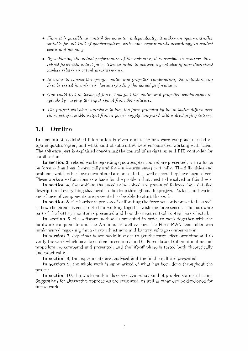
• Since it is possible to control the actuator independently, it makes an open-controllersuitable for all kind of quadrocopters, with some requirements accordingly to controlboard and memory.
• By achieving the actual performance of the actuator, it is possible to compare theo-retical force with actual force. This in order to achieve a good idea of how theoreticalmodels relates to actual measurements.
• In order to choose the specic motor and propeller combination, the actuators canrst be tested in order to choose regarding the actual performance.
• One could test in terms of force, how fast the motor and propeller combination re-sponds by varying the input signal from the software.
• The project will also contribute to how the force provided by the actuator diers overtime, using a stable output from a power supply compared with a discharging battery.
1.4 Outline
In section 2, a detailed information is given about the hardware components used onIqarus quadrocopter, and what kind of diculties were encountered working with them.The software part is explained concerning the control of navigation and PID-controller forstabilisation.
In section 3, related works regarding quadrocopter control are presented, with a focuson force estimations theoretically and force measurements practically. The diculties andproblems which other have encountered are presented, as well as how they have been solved.These works also functions as a basis for the problem that need to be solved in this thesis.
In section 4, the problem that need to be solved are presented followed by a detaileddescription of everything that needs to be done throughout the project. At last, motivationand choice of components are presented to be able to start the work.
In section 5, the hardware process of calibrating the force sensor is presented, as wellas how the circuit is constructed for working together with the force sensor. The hardwarepart of the battery monitor is presented and how the most suitable option was selected.
In section 6, the software method is presented in order to work together with thehardware components and the Arduino, as well as how the Force-PWM controller wasimplemented regarding force curve adjustment and battery voltage compensation.
In section 7, experiments are made in order to get the force eect over time and toverify the work which have been done in section 5 and 6. Force data of dierent motors andpropellers are compared and presented, and the lift-o phase is tested both theoreticallyand practically.
In section 8, the experiments are analysed and the nal result are presented.In section 9, the whole work is summarized of what has been done throughout the
project.In section 10, the whole work is discussed and what kind of problems are still there.
Suggestions for alternative approaches are presented, as well as what can be developed forfuture work.
7

2 | Background
This section will provide theory and specication of the hardware components used for controlling
the motors on Iqarus quadrocopter. It will also give an explanation of how the quadrocopter works
concerning stabilisation and navigation, to be able to proceed the work and process throughout the
report.
2.1 Hardware components of the actuator line
The actuator line on the quadrocopter is made up of a Lithum Polymer (Lipo) battery,ESC, motors and propellers. The ESC gets power from the battery and an input signalin form of a Pulse Width Modulation (PWM)-signal from the control board. The ESCthen translates the PWM commands into a 3-phase signal to the Brushless Direct Current(BLDC) motor, which generates a magnetic eld inside the motor to rotate the shaft.
2.1.1 Motors
The motors which are currently used on the Iqarus quadrocopter are T-motor KV1100(MT2208) (see gure 2.1). The motors are the key aspects regarding the actuator control.The performance of the motor when spinning delivers a torque, which will together withthe propeller deliver a thrust (force in upward direction).
Figure 2.1: T-motor KV1100
The T-motor KV1100 is a type of BLDC electronical motor, and further dened asan Outrunner. The BLDC motors have better eciency and longer life time comparedto Brushed Direct Current (BDC) electronical motors, due to the lack of brushes. Theyalso have a more accurate positioning of the rotor, relying on sensors (usually Hall-eectsensors) inside the motor, which tells the current rotor position [1]. The Outrunners areusually used for quadrocopter applications heavier than 0.5kg [2], since it can provide 5to 7 times higher torque then the Inrunners. On the Outrunners, the magnets are placedon the inside part of the shield and the coils forms the stationary center. This makes thewhole outer part of the motor spin, including the rotor where the propeller is attached (seegure 2.2).
8
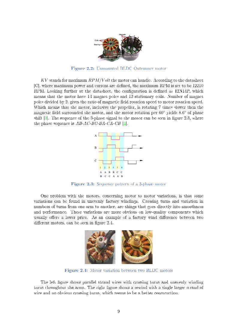
Figure 2.2: Unmounted BLDC Outrunner motor
KV stands for maximum RPM/V olt the motor can handle. According to the datasheet[C], where maximum power and current are dened, the maximum RPM is set to be 12210RPM. Looking further at the datasheet, the conguration is dened as 12N14P, whichmeans that the motor have 14 magnet poles and 12 stationary coils. Number of magnetpoles divided by 2, gives the ratio of magnetic eld rotation speed to motor rotation speed.Which means that the motor, inclusive the propeller, is rotating 7 times slower then themagnetic eld surrounded the motor, and the motor rotation per 60 yields 8.6 of phaseshift [3]. The sequence of the 3-phase signal to the motor can be seen in gure 2.3, wherethe phase sequence is AB-AC-BC-BA-CA-CB [1].
Figure 2.3: Sequence pattern of a 3-phase motor
One problem with the motors, concerning motor to motor variations, is that somevariations can be found in unevenly factory windings. Crossing turns and variation innumbers of turns from one arm to another, are things that goes directly into smoothnessand performance. These variations are more obvious on low-quality components whichusually oers a lower price. As an example of a factory wind dierence between twodierent motors, can be seen in gure 2.4.
Figure 2.4: Motor variation between two BLDC motors
The left gure shows parallel strand wires with crossing turns and unevenly windingturns throughout the arms. The right gure shows a rewind with a single larger strand ofwire and no obvious crossing turns, which seems to be a better construction.
9

Propellers
The propellers currently mounted on the Iqarus quadrocopter are of type APC 9x4.7 (seegure 2.5). They are made of composite, which is known to be a sti and hard material.The standard measure of propellers is "diameter x pitch" in inches, so the length of thepropeller is 9 inches (22.86 centimetres) and the pitch is 4.7 inches (11.93 centimetres).The pitch refers to the angle of incidence at 3
4 of the radius. Using the angle, the pitchis converted into inches by how far the propeller would move after one revolution [4].However, discussion says that pitch measurement is not proved to be 100% exact, sincethe propellers slips in air a bit.
Figure 2.5: APC propeller 9x4.7
According to the airfoil data provided by the motor manufacturers [C], the four pro-pellers are able to lift Iqarus quadrocopter's weight of 1.2kg with a throttle of approximately56% using 11.1V supply. There are four propellers mounted on the quadrocopter, in whichtwo of them will give a moment in Clockwise (CW) direction (pulling) and the other twoin Counter Clockwise (CCW) direction (pushing). The two CW and CCW propellers aremounted opposite each other, to avoid any undesirable yaw rotation. The smaller thepropeller the better manoeuvrability [2], but at the same time the higher the rotor speedhas to be to get the same lift. A greater angle of the blade will give more lift while beingheavier for the motor to spin. A well balanced propeller is important, especially in highrotor speeds [5], since an unbalanced propeller will induce vibrations into the system. In [6]it is shown that the vibrations disturbs the IMU-data by ±6. The blade geometry doesnot either have to be exact from propeller to propeller, even though APC-propellers areknown to be reliable and well-balanced from factory.
2.1.2 Lipo battery
The power source currently used on the Iqarus quadrocopter is a Lipo battery Tripple 3S3000mAh (see gure 2.6), from where all the power is delivered to the quadrocopter. Thebattery is a standard three cell Lipo battery and weights 254 grams. It can deliver up to60A of nominal discharge and be loaded with 15A.
Figure 2.6: Lipo battery Tripple 3S 3000mAh
Suggested batteries for multirotor applications are usually Lipo batteries, since they
10
can deliver a high current for an extended time and are generally smaller in size. All of thebatteries have an amount of internal resistance, also known as Equivalent Series Resistance(ESR). As higher C-rating as lower internal resistance. As more the pack is used, as higherinternal resistance which makes them run warmer and more current will be pulled out.The nominal voltage of every cell is 3.7V, which makes the total voltage of the battery11.1V. Every cell can be charged from 2.7V to 4.23V, which in total means 8.1V to 12.69V.However, it is not recommended to discharge the battery to under 9V, since it can damagethe battery and decrease the life-time. The motors runs approximately at 4A under ight,and the ight time can therefore be estimated to 11.25 min using following formula 2.1.2,also used in [7].
t =Nrcells · 60min
Adrawn ·Nrmotors= 11.25 min (2.1)
The maximum power of the Lipo battery is 756W, while delivering a current of 16A(four motors) the power demand gets 201.6W. Internal resistance opens up a huge andcomplex topic of how to accurately calculate voltage drop in the pack and the total amountof watts being expended in form of heat within the pack. The internal resistance can stillbe estimated by measuring the current in two voltage levels, using the following formula.
Rint =VdiffAdiff
(2.2)
As well as the theoretical discharge rate, in terms of voltage over time, can be estimatedusing the following formula.
V
t=
Vfullbattery3000(mAh)·60(min)
A
=V ·A180
=12.69 · 4
180= 0.282 V/min (2.3)
2.1.3 ESC
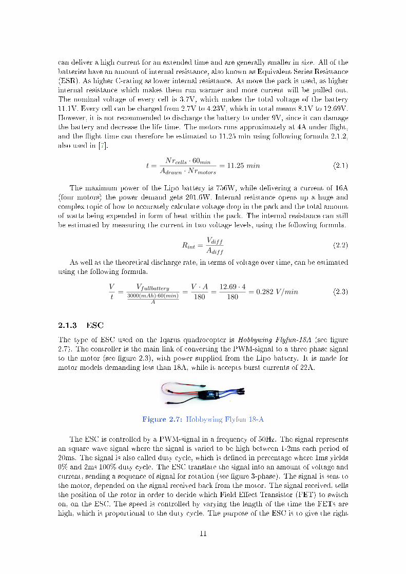
The type of ESC used on the Iqarus quadrocopter is Hobbywing Flyfun-18A (see gure2.7). The controller is the main link of converting the PWM-signal to a three phase signalto the motor (see gure 2.3), with power supplied from the Lipo battery. It is made formotor models demanding less than 18A, while it accepts burst currents of 22A.
Figure 2.7: Hobbywing Flyfun 18-A
The ESC is controlled by a PWM-signal in a frequency of 50Hz. The signal representsan square wave signal where the signal is varied to be high between 1-2ms each period of20ms. The signal is also called duty cycle, which is dened in percentage where 1ms yields0% and 2ms 100% duty cycle. The ESC translate the signal into an amount of voltage andcurrent, sending a sequence of signal for rotation (see gure 3-phase). The signal is sent tothe motor, depended on the signal received back from the motor. The signal received, tellsthe position of the rotor in order to decide which Field Eect Transistor (FET) to switchon, on the ESC. The speed is controlled by varying the length of the time the FETs arehigh, which is proportional to the duty cycle. The purpose of the ESC is to give the right
11
signal in the right amount of time, which are things that goes directly into smoothnessand performance. The ESC never seemed to be a problem throughout the Iqarus project,so no other type of ESC was concluded to be tested in this project.
2.2 Control of Iqarus quadrocopter
2.2.1 Stabilisation
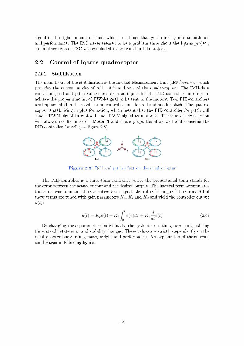
The main heart of the stabilisation is the Inertial Measurement Unit (IMU)-sensor, whichprovides the current angles of roll, pitch and yaw of the quadrocopter. The IMU-dataconcerning roll and pitch values are taken as inputs for the PID-controller, in order toachieve the proper amount of PWM-signal to be sent to the motors. Two PID-controllersare implemented in the stabilisation controller, one for roll and one for pitch. The quadro-copter is stabilising in plus formation, which means that the PID-controller for pitch willsend +PWM-signal to motor 1 and -PWM-signal to motor 2. The sum of these actionwill always results in zero. Motor 3 and 4 are proportional as well and concerns thePID-controller for roll (see gure 2.8).
Figure 2.8: Roll and pitch eect on the quadrocopter
The PID-controller is a three-term controller where the proportional term stands forthe error between the actual output and the desired output. The integral term accumulatesthe error over time and the derivative term equals the rate of change of the error. All ofthese terms are tuned with gain parameters Kp, Ki and Kd and yield the controller outputu(t):
u(t) = Kpe(t) +Ki
∫ t
0e(τ)dτ +Kd
d
dte(t) (2.4)
By changing these parameters individually, the system's rise time, overshoot, settlingtime, steady-state error and stability changes. These values are strictly dependently on thequadrocopter body frame, mass, weight and performance. An explanation of these termscan be seen in following gure.
12

Figure 2.9: Constants eect on PID-controller
There are alternative ways of nding the proper Kp, Ki and Kd constants, such as theZiegler-Nichols method, the Cohen-Coon method and with manual tuning. The Ziegler-Nichols method was chosen to be rst tested in the Iqarus project, since it is a well knownmethod for quadrocopter application and creates a good lter for rejecting disturbances.To nd the constants, Kp, Ki and Kd are set to zero and Kp is increased until the outputoscillates with constant frequency and amplitude. The control constants are then set froma table [8]. The Ziegler-Nichols method could however not be completed since the test rignever oscillated, so a manual tuning was made instead. The found constants were set to beKp = 2.2 and Kd = 0.4. It was however strongly dependent on the platform itself, whichwas changed throughout the project in terms of weight and placement of extra components.The overall conclusion is that the constant are going to be changed, either if the platformchanges or the amount of error value changes from PWM-signal to force data.
2.2.2 Navigation
The Iqarus quadrocopter stabilize in a plus-formation, while movements are done in ax-formation. The movements commands can either come from the Computer-Vision sys-tem or a Joystick controller. The movements commands are done by combining adjacentmovement commands in the plus formation, which means that movement for forward isobtained by combining the movement commands for forward and right in plus-formation(see gure 2.10).
Figure 2.10: Movement commands on the quadrocopter
The stabilisation controller only takes an input of the calculated degree of movement,to be assumed in the PID-controllers for roll and pitch. This means that no further changeshave to be made in the new stabilisation controller, since it can be implemented in thesame way as earlier while changing Kp, Ki and Kd settings. A code snippet of the PID-
13
controller concerning pitch can be seen below, where "PITCH MOVE OFFSET" is thedesired movement in degrees.
P = (PITCH_DESIRED+PITCH_MOVE_OFFSET) - att.pitch;
I += (PITCH_DESIRED-att.pitch)*timeChange;
D = ((P - errorPitchLast)/timeChange);
2.2.3 RPM measurement
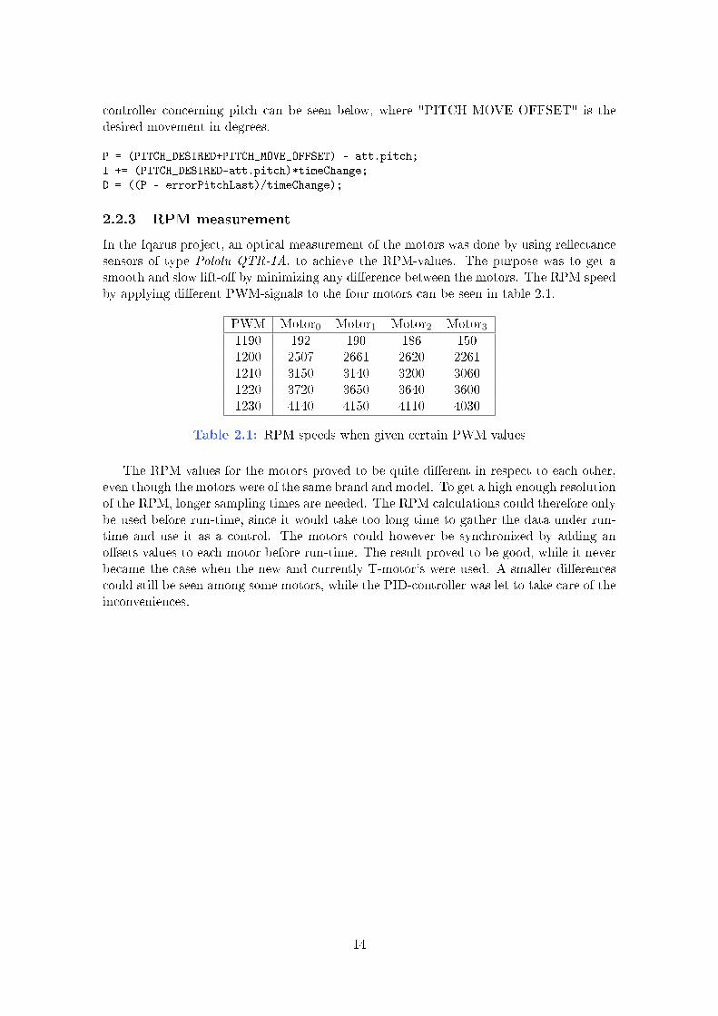
In the Iqarus project, an optical measurement of the motors was done by using reectancesensors of type Pololu QTR-1A, to achieve the RPM-values. The purpose was to get asmooth and slow lift-o by minimizing any dierence between the motors. The RPM speedby applying dierent PWM-signals to the four motors can be seen in table 2.1.
PWM Motor0 Motor1 Motor2 Motor31190 192 190 186 1501200 2507 2661 2620 22611210 3150 3140 3200 30601220 3720 3650 3640 36001230 4140 4150 4110 4030
Table 2.1: RPM speeds when given certain PWM values
The RPM values for the motors proved to be quite dierent in respect to each other,even though the motors were of the same brand and model. To get a high enough resolutionof the RPM, longer sampling times are needed. The RPM calculations could therefore onlybe used before run-time, since it would take too long time to gather the data under run-time and use it as a control. The motors could however be synchronized by adding anosets values to each motor before run-time. The result proved to be good, while it neverbecame the case when the new and currently T-motor's were used. A smaller dierencescould still be seen among some motors, while the PID-controller was let to take care of theinconveniences.
14
3 | State of the Art
The most relevant related work is the Iqarus project, since this project is based with the same hard-
ware components and software strategies as well as testing will be done on the same prototype used
in the Iqarus project. This section will represents what other have done in this area and encoun-
tered diculties, regarding quadrocopter control and estimation of force measurements concerning
theoretical and practical approaches.
3.1 Related works
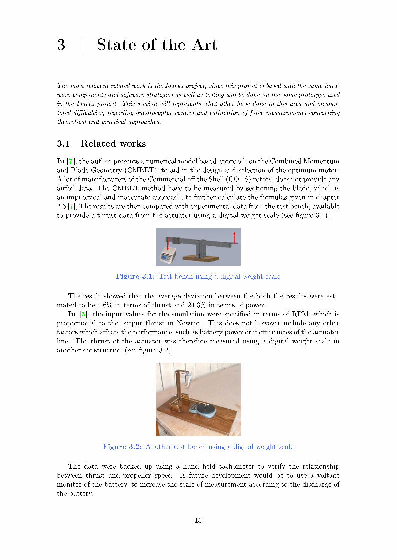
In [7], the author presents a numerical model based approach on the Combined Momentumand Blade Geometry (CMBET), to aid in the design and selection of the optimum motor.A lot of manufacturers of the Commercial o the Shell (COTS) rotors, does not provide anyairfoil data. The CMBET-method have to be measured by sectioning the blade, which isan impractical and inaccurate approach, to further calculate the formulas given in chapter2.6 [7], The results are then compared with experimental data from the test bench, availableto provide a thrust data from the actuator using a digital weight scale (see gure 3.1).
Figure 3.1: Test bench using a digital weight scale
The result showed that the average deviation between the both the results were esti-mated to be 4.6% in terms of thrust and 24.3% in terms of power.
In [5], the input values for the simulation were specied in terms of RPM, which isproportional to the output thrust in Newton. This does not however include any otherfactors which aects the performance, such as battery power or ineciencies of the actuatorline. The thrust of the actuator was therefore measured using a digital weight scale inanother construction (see gure 3.2).
Figure 3.2: Another test bench using a digital weight scale
The data were backed up using a hand held tachometer to verify the relationshipbetween thrust and propeller speed. A future development would be to use a voltagemonitor of the battery, to increase the scale of measurement according to the discharge ofthe battery.
15

In [9], it is said that motors and propellers are dicult to model because of the demand-ing non-linearities imposed by the aerodynamic eects on the propeller. By conducting asimple experiments using a digital weight scale, the motor and propeller combination couldbe tested for actual performance. The force was further calculated as following.
F (N) = gm
s2(scale reading(Kg) − zero volt reading(Kg)) (3.1)
The result obtained by measuring the thrust of the four actuators on the quadrocopter,using the same model of motor and propeller, can be seen in gure 3.3.
Figure 3.3: Thrust data of four motors (Sikiric's)
The four curves represent the force output provided by the actuators, and a quite smallmotor to motor variation could be found between them. A linear approximation (the blueline), was obtained using a least square method on the mean thrust. Further on, a transferfunction were obtained to transfer the servo output signal to force, in order to model thesystem in the software. A representative rise time of 0.3 was conducted and the naltransfer function which was found, can be seen in following formula.
F (s) =0.027843
0.1s+ 1(servo output(s)) (3.2)
Two dierent PID-controllers were compared to each other. A straight forward PID-Acontroller where Kp, Ki and Kd constants were theoretically calculated and implementedin the software. The non-linearities of the motors were however not considered at all. ThePID-B controller was used in a dierent approach, where the motor signal was interruptedand set to zero at intervals calculated by the PID-controller. The advantages was thatthe non-linearities posed by the aerodynamic eects on the propellers did not becameas dominant as for the PID-A controller. The later approach was concluded to be thebetter approach. However, this technique brings diculties such as slower dynamics in thecontroller because of longer time delays.
A power supply was used during tests to maintain a stable voltage. One motor hadmaximum a voltage of 9.6V and a current limit of 10A, which required the battery toprovide 40A. Since it was hard to nd a battery with such small voltage and high current,a larger battery was used together with a voltage regulator. This allowed the force to beconstant, and distinguished the need of using a battery monitor. With 40A of current run-ning in the cables next to the signal cables, it was important to not overlook the shielding.The signal could get contaminated with electrical and magnetic-eld interference.
16

In [4], a quadrocopter was built using the same board used in Iqarus (Arduino Mega2560)and in [5]. The tuning of the PID-controller was made using Ziegler-Nichols method andLambda tuning. It was stated, "that not all of the propellers are equal, neither do theyhave a perfect weight distribution since they are manufactured in large quantities". Theplastic propellers required careful balancing to avoid any vibrations composed by runningat high RPMs. The propellers were therefore rotated on a fastened spindle shaft by hand,and their nal resting position were observed. If the blades were perfectly balanced, theywould end up in a horizontal position which was however not the case, since the bottomsection of the blade proved to be heavier. By modifying the propellers using varnish andsanding, the propellers could be balanced all again.
In [5], another approach for balancing the blades were made by using a Hobby PropBalancer (see gure 3.4). Clear and low prole tape was applied to compensate anyinherent instability on the propeller.
Figure 3.4: Hobby Prop Balancer
In [10], the authors presents an unique approach for calculating the thrust demandat a certain height, to be used for the altitude controller. Since the delivered thrust is afunction of the command signal and the battery voltage, the feed forwarded term uoff isincluded in the following formula 3.1 to achieve the proper thrust uh(t).
uh(t) = Kpeh(t) +Ki
∫ t
0eh(τ)dτ +Kd
d
dteht+ uoff (t) (3.3)
Where the error is eh(t) = z∗ − z and z∗ denotes the desired height, z is the currentmeasurement and uoff is the feed forwarded term. The true height measurement z iscoupled with pitch and roll angle and can be calculated as following z = cos(θ) cos(φ)z,where z is the sensor measurement. The measured nominal thrust command for hoverversus the battery voltage is shown in gure 3.5.
Figure 3.5: Hover thrust vs. Battery voltage
17

As higher voltage level on the battery as lower thrust is needed for hovering. It wasstated that the Lipo battery used, also had a non-linear discharge curve. The voltage dropssignicantly at the start and at the end of discharge, and is continuously decreasing at themid-zone.
In [6], it is said from experiments that the relation between the control inputs and gen-erated thrust is approximately linear across the regime of useful operation. The identiedrising time was set to be 0.2s resulting in a rst order transfer function. The PID-controllerwas derived by Ziegler-Nichols method and was then manually tuned.
3.2 Summary
After research, it was found that other works have been done in this area with similarproblems concerning motors [9] and propeller [4] [5] characteristics, in relation to theIqarus project. Theoretical estimations of the force have been done, for modelling thesystem in software [7] [9] [10]. It was also stated that the battery strictly aects the forceof the actuator [5] [10]. Force measuring of the actuator have been done in curiosity, bymeasuring the force using digital weight scales in dierent constructions [7] [5]. The datahave however not been used for controlling the actuators, such as the proposal and purposefor this project.
18

4 | Problem Statement
Mainly problems regarding the actuator line have been discussed in section [3]. This section will
aim towards the problem on how to avoid the dierences on the actuator line, as well as how to use
the information for controlling the actuators regarding force commands. At rst, an explanation of
the problem that need to be solved, and later a section of choice and specication of the components
that will be used throughout the project.
4.1 Problem to be solved
The problem to be solved, is to minimize system performance sensitivity due to motordierences such was found in [9] (see gure 3.3) and [2] (see table 2.1). Another problemto be solved, is the dierent thrust aects according to dimensional dierences of thepropellers such was found to be the case in [4] [5] [2]. Other factors which directly aectthe force, such as the voltage level of the battery [5] [10] [6] and ESC characteristics, alsoneeds to be solved.
Figure 4.1: The problems are going to be solved
By gathering the force data together with the battery voltage, these problems can beavoided and therefore solved. Further problems involves to nd a method for adjusting theforce curve to the proper output depending on the battery voltage level, and to test thesystem in the lift-o phase.
4.2 Project description
To be able to measure the force, a type of force sensor need to be found such that it cangive enough precision and be able to output an electronic signal. Such sensor was found tobe Vetek Single Point Load Cell 1kg, a load cell which can measure up to 1kg of pressure.The load cell have to be mounted in a way that lets the motor and propeller congurationbe mounted of top of it, to achieve the force in an upward direction (see gure 4.2).
Figure 4.2: Vetek Single Point Load cell
The output of the load cell is just a few millivolts, so it would need to be ampliedin a circuit using an Instrumentation Amplier (INA). Such component was chosen to be
19

INA125P, which was also used in [11] [12]. The amplied output is going to be connectedto one of the analog inputs on the microcontroller, from where the PWM-signals are sentand the motors are controlled. The project is provided by the choice of using one of the twomicrocontrollers, Arduino Mega2560 or Arduino Due. The dierences and motivations willbe discussed in section [4.3]. By sending values of PWM-signals, force and battery voltagevalues will be gathered at the same time and stored into the memory of the Arduino forlater use. See gure 4.3 for the system concerning gathering the data before run-time.
Figure 4.3: Gather data before run-time
When the gatherings are done for every motor, a Force-PWM controller will be im-plemented such that it takes the desired force as input and outputs the correspondingPWM-signal to the ESC. See gure 4.4 for the system concerning the process under run-time.
Figure 4.4: Process the data under run-time
The desired force command for the certain motor is received, and the gathered force andbattery data for the same motor needs to be present in the controller. The force commandwill be adjusted depending on the battery voltage when the data was gathered, in relationto the current battery voltage which is read from a battery monitor. The Force-PWMcontroller will make sure it outputs the correct force command at the current voltage level,by sending the corresponding value of PWM-signal.
4.3 Choice and specication of components
4.3.1 Arduino Mega2560 vs. Arduino Due
The project were given two possibilities of which microcontroller to use, in order to choosethe most proper one for the task. Arduino Mega2560 Rev3 is currently used on Iqarus,which would be a safe choice since no further changes have to be made. On the otherhand, Arduino Due is faster and the rst Arduino board which uses an 32-bit ARM coreprocessor. The Due is a new microcontroller, which was released in September 2012 whileMega2560 was released in December 2012. A comparison between the specications canbe seen in table 4.1.
20

Arduino Mega2560 Arduino DueMicrocontroller Atmega2560 AT91SAM3X8EClock speed 16MHz 84MHz
Operating voltage 3.3V 5VDigital I/O Pins 54 (15 PWMs) 54 (12 PWM)Analog Inputs 16 12
Analog Bit Resolution 10-bit 12-bitAnalog Outputs - 2 (DAC)
DC Current per I/O Pin 40 mA 130 mADC Current for 3.3V Pin 50 mA 800 mADC Current for 5V Pin - 800 mA
Flash Memory 256 KB 512 KBSRAM 8 KB 96 KB
EEPROM 4 KB -
Table 4.1: Comparision between Mega2560 and Due
The highlighted rows shows the most signicant comparison. Arduino Due providesa 12-bit resolution of the Analog to Digital Converter (ADC), which gives 1024 possiblevalues while Mega2560 with 10-bits resolution gives 4096 possible values. The sensitiv-ity for Mega2560 is 5V/1024values = 4.88mV/value, and for Due 3.3V/4096values =0.8mV/value. Due's sensitivity would benet the choice, while not having any availableElectrically Erasable Programmable Read-Only Memory (EEPROM) which is strictly nec-essary. Since Due is a new release, and the open-source Arduino Development Kit is nowin BETA stage, there exists solutions on how to use the ash memory for storing non-erasable data, yet not been established in any conrmed release. While Due only operatesat 3.3V as well as the load cell's sensitivity is 5 mV/g after amplication (compared toDue's sensitivity of 0.8 mV/bit), it was stated that Arduino Mega2560 would be a betterchoice for platform.
4.3.2 Force sensor
The force sensor is a type of Single point load cell 1k, manufactured by Vetek. The loadcell is restricted to a maximum load of 1kg, which was chosen for the task. The load cellis constructed with an aluminium material and have four internal strain gauges (see gure4.5).
Figure 4.5: Load cell construction and strain gauges
As the material holding the strain gauges getting bent by an outside force, the straingauges sense the deformation on the material (in terms of resistance) and outputs thedierence between them according to the Wheatstone bridge conguration (see gure 4.6).
21

Figure 4.6: Wheatstone bridge circuit
The output VG of the Wheatstone bridge circuit is calculated as following.
Vg =
(Rx
R3 +Rx− R2
R1 −R2
)Vs (4.1)
When there is no load on the load cell, the output is zero. According to the datasheet[B], the sensitivity is 1mV/V ±20%. This means that if Vin = 5V, the output would be 5mVat 1kg. The output would need to be amplied 1000 times to meet the maximum voltageallowed on the analog input of the Arduino. INA125P [A] will be used for amplifying thesignal, which is a small Integrated Circuit (IC) normally used for pressure applications. Intheory, with Arduino Mega2560 sensitivity of 4.88mV/value, the gain would need to beset accordingly.
G =Arduino (mV/value)
Loadcell (mv/g)=
4.88
0.005= 976 (4.2)
4.3.3 Actuator line
The currently motor used on the quadrocopter is T-motor KV1100 (MT2208) [C]. Anothertype of motor that will be tested is T-motor KV900 (MT22016-11) [D], which is a smallermotor comparing the KV value while having a higher maximum limit for continuous powerand current. T-motor KV900 can deliver a maximum of 9450 RPM while the KV1100 candeliver 12100 RPM. By looking at the datasheet of the two motors, a comparison betweenthem can be obtained. Running them at 11.1V and 75% throttle, with APC-propeller10x3.8, the performance data can be seen in following table 4.2.
Amps(A) Watts(W) Th(G) Th(OZ) RPM E(G/W) E(OZ/W)
KV900 7,9 87,69 670 23,63 6000 7,64 0,27KV1100 7,6 84,63 590 20,81 5600 6,99 0,25
Table 4.2: Motor KV900 and KV1100 with prop 10x3.8
Three type of propellers will be tested, everyone with the same brand of APC, butwith three dierent size of dimensions 9x4.7, 10x3.8 and 11x4.7. Again, looking at thedatasheets of the two motors it is found that 9x4.7 and 10x3.8 were tested on KV1100,and 10x3.8 and 11x4.7 were tested on KV900. See table 4.3 for the performance data using11.1V with 75% throttle.
22

Prop size Amps(A) Watts(W) Th(G) Th(OZ) RPM E(G/W) E(OZ/W)
KV900 10x3.8 7,9 87,69 670 23,63 6000 7,64 0,2711x4.7 8,6 95,46 730 25,75 5298 7,65 0,27
KV1100 9x4.7 6,4 71,04 500 17,64 6600 7,04 0,2510x3.8 7,6 84,63 590 20,81 5600 6,99 0,25
Table 4.3: Motor KV900 and KV1100 with prop 9x4.7, 10x3.8 and 11x4.7
The motor with higher KV gives an overall weaker output using 10x3.8 propeller, andspecically RPM for interest. As smaller dimension of the propeller as higher velocity interms of RPM, since it gets less heavier for the motor to spin.
Only one type of ESC HobbyWing Flyfun 18A will be used in this project, which isthe same used in Iqarus. Even though the maximum current of T-motor KV900 is 20A, itwould never increase the limit of 18A using these propellers. The Lipo battery is the sameused in Iqarus project. It maintains to t the requirements as it can deliver up to 60A.
4.4 Summary
A denition of the problem was captured, concerning the problems throughout the Iqarusproject which are supported by the problems from other works in section [3]. A solutionto the problem was proposed using a load cell to achieve the force. The work that thisthesis will cover were formulated, concerning setting up the load cell, gathering the databefore run-time and working with the data in the Force-PWM controller under run-time.Section [4.3.1] were given to further understand the area of the work that will be covered.The rst convenience, would be to get the load cell to work.
23

5 | Hardware Process
This section will describe the process of how to get the load cell to work, and how the instrumentation
amplier is settled. This section will also describe how the battery monitor is built and tested in
dierent circuits to select the best approach.
5.1 Force sensor
5.1.1 Mechanical construction
The force sensor can sense weights in both directions. While it is recommended, due tothe construction, to follow the black arrow (see gure 5.1). It does not matter where theforce is applied, while it benets the result if the plate is placed as near the load cell aspossible.
Figure 5.1: Pressure applied to load cell
A perpendicular aluminium plate (1) was mounted on the front side of the load cell(see gure 5.2), so the motor and propeller combination could be mounted on top of it.The plate was screwed from the side and the plate was ensured to have a small distance(d) from the load cell. Another plate (2) was mounted on top of the load cell, in order tox the position.
Figure 5.2: Plates placed on load cell
The load cell was later strapped in a "working-bench" in order to x the horizontalplate. A picture of the construction can be seen in gure 5.3.
Figure 5.3: Final mechanical construction
24

5.1.2 Circuit construction
The load cell have ve coloured cables attached, in which Red corresponds to +Excitation,White Excitation, Green +Signal, Blue -Signal, Grey Earth. It is supplied by 5V andboth of the ground wires are grounded. The red and white cables are connected to the +and - inputs of the INA125P. According to the datasheet of INA125P [A], two circuits ofinterest can be obtained (see gure 5.4).
Figure 5.4: Suggested circuits for INA125P
The circuit to the left shows how the transistor can be used to improve the outputdrive capability of the voltage reference. The transistor also serves to remove power fromthe INA125P. The circuit to the right shows the overall connections and how the externalbridge can be connected. The resistance of RG determines the gain and accordingly to [A],following table can be obtained.
Figure 5.5: Resistor values to specify the gain
A potentiometer will be used to adjust and determine the proper gain in practice.One other potentiometer will be used to determine the oset voltage, in which the bridge"resting position" can be adjusted. Gain and oset resistance goes hand in hand. Ashigher gain as higher the oset voltage get. It is important to choose the gain to maximummeasure 1kg, and to choose the oset voltage as near to zero as possible, which will becovered in the next section [5.1.3]. The nal circuit concerning INA125P settings beforethe load cell was calibrated can be seen in following gure.
25
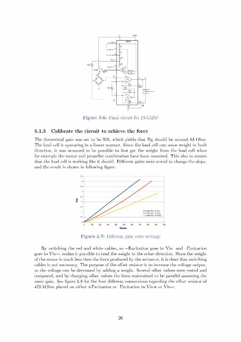
Figure 5.6: Final circuit for INA125P
5.1.3 Calibrate the circuit to achieve the force
The theoretical gain was set to be 976, which yields that Rg should be around 63 Ohm.The load cell is operating in a linear manner. Since the load cell can sense weight in bothdirection, it was assumed to be possible to rst get the weight from the load cell whenfor example the motor and propeller combination have been mounted. This also to ensurethat the load cell is working like it should. Dierent gains were tested to change the slope,and the result is shown in following gure.
Figure 5.7: Dierent gain value settings
By switching the red and white cables, so +Excitation goes to Vin- and Excitationgoes to Vin+, makes it possible to read the weight in the other direction. Since the weightof the motor is much less then the force produced by the actuator, it is clear that switchingcables is not necessary. The purpose of the oset resistor is to increase the voltage output,so the voltage can be decreased by adding a weight. Several oset values were tested andcompared, and by changing oset values the lines maintained to be parallel assuming thesame gain. See gure 5.8 for the four dierent connections regarding the oset resistor of470 kOhm placed on either +Excitation or -Excitation to Vin+ or Vin+.
26

Figure 5.8: Oset resistor set in four dierent ways
As it can be seen from the gure, the oset resistor should be placed between +Ex-citation and +Vin which corresponds to the yellow line. The yellow line is then workinglike the red, when +Excitation is connected to -Vin. It is strictly necessary that the volt-age does not falls below 0V after the weight been placed, since it would destroy for laterreadings. The oset value in terms of grams was found to be 175g according to the yellowline. Subtracting the weight of the perpendicular plate of 60g the oset is set to be 115g.The weight of the T-motor KV1100 is 68g, which yields a margin of 57g to be added forheavier motors. A nal value of 470 kOhm proved to be good enough.
The nal equation for the load cell, using oset resistance of 470 kOhm and gainresistance of 63 Ohm, was achieved by placing weights in the down direction and bylooking at the result. The load cell operates in a linear manner, and the equation for theline could be found in Excel (see gure 5.9).
Figure 5.9: Equation found in Excel
The y-axis represents values of grams and the x-axis number of values read from theADC of Arduino Mega2560. The red line shows the maximum readable values of 870 valuesand 650 grams, when maximum pressure is applied. The gain was further increased byminimizing the gain resistance to 58.4 Ohm, to achieve a greater range of the readings.The nal equation according to the yellow line, was found to be following.
f(x) = 0.7x− 150.46 (5.1)
27

5.1.4 LP-lter and EMI rejection
A LP-lter was needed to be implemented, to get rid of noise (in and external) and Electro-magnetic Interference (EMI). First, second and third-order LP-lters were tested, as wellas dierent values for the resistors and capacitors. The rst and second-order lters didnot seem good enough, so a third-order lter were chosen. See gure 5.10 for tests usingdierent LP-lters as well as the software delay between every increment of PWM-signal.
Figure 5.10: LP-lters and software delay timings
It is good to choose a strong LP-lter as possible, without introducing too long delaytime. The circuit was tested visually by inspecting the reaction of the signal, on anoscilloscope, when pressure was applied on the load cell. The nal LP-lter was chosenaccordingly to the blue line, which shows a third-order LP lter with R1 = 470kOhm,R2 = 100kOhm, R3 = 22kOhm and C1 = 1uF, C2 = 2.2uF + C3 = 10uF. The cut-o frequency got 6.99 Hz and the reaction time proved to be good. The delay time forthe test was set to 300ms, while 200ms was nally chosen since it gave the same result.Even though a LP-lter was implemented, there were still interference obtained from theresults. Ground and voltage cables from the load cell were twinned together, as well as +and Excitation cables. The circuit was further improved by adding decoupling capacitors(0.1uF electrolyte and 0.1nF ceramic) between Arduino's 5V output and the circuit, whichin turn feeds the load cell. One other ceramic capacitor of 0.1uF was placed betweenVrefout and the base input of the transistor. Two other ceramic capacitors of 10nF wereplaced on +Vin and -Vin of the INA125P. The result proved to be better with minimizedinterference.
5.1.5 Gather data from the load cell
Equation 5.1.3 was programmed into the Arduino Mega2560, with the signal from the LP-lter connected to AN0. The program iterates trough all possible PWM-signals and storesthe force data temporary. A power supply was used, which was limited to provide 3.16A. Byparallel connecting the output of the power supply, a current of 6.32A could be delivered.The rst motor to be tested was T-motor KV1100 with APC 9x4.7, and according to [D]the thrust is 500g at 11.1V when the current is 6.4A which (75% throttle). The result ofthe gathered data can be seen in following gure.
28

Figure 5.11: PS and Lipo dierence on force output
The force curves can be approximated to a second order function, in a form of f(x) = x2.The Lipo battery and the power supply give the same result, while the Lipo can delivera higher current. This means that the power supply can be used during tests, while inight a battery will be used. Due to power loss, the Lipo battery can not manage togive a higher force than approximately 600g. Since the motor was applied with 12V, itreached the maximum point earlier at 62% throttle, then if it would be applied with 11.1V.Dierent voltages were applied using a power supply to obtain the dierences (see gure5.12).
Figure 5.12: Force output of dierent PS voltages
As it can be seen, it is not recommended that the battery falls below 9V, and it is alsonot recommended that it falls below 9.7V for this motor and propeller conguration. Theforce curves seems to be relative each other, which means that the oset from one curve toanother yields for the rest of the curves at the same force. This would make some thingssimpler, but unfortunately it is not the case. By looking at how many PWM/Volt arechanged at 300g, table 5.1 can be obtained.
29

PS (V) PWM Di. (PWM/Volt)
9.7 1572 56.6710 1555 4010.5 1535 4211 1514 29.0912.1 1482 3512.5 1468 3213 1452 2614 1426 28
Table 5.1: PWM/Volt change of dierent input voltages
It is stated that as higher the supply voltage gets, as lower the dierence in PWM-signal. It will be an important factor for deciding the approach for force curve adjustmentin section [6.3].
5.2 Battery monitor
The battery monitor will be used before and under run-time. It is required that thecircuit will draw as little current as possible to save battery time. Earlier approacheshave been made using hardware components to stop the ight whenever the battery fallsbelow a certain voltage. These approaches that will be presented here, requires the batterymonitor to be accessed from the software in order to adjust and control the actuators. Someproblems were encountered such as the output from the battery monitor is giving lowervalues as the PWM-signal is increasing, which gives a higher power demand to the ESC.The problem will be discussed in section [6.2]. The battery monitor was not connecteddirectly at the power source referring to gure 4.3, it was however connected betweenthe power source and ESC since it provides the possibility to exchange power source. Twomainly circuits have been investigated, a simple voltage divider and a voltage divider usinga BJT-transistor circuit. Both Lipo battery and power supply were tested in order to seethe dierence.
5.2.1 Voltage divider
The ratio of the resistors were chosen to scale down the voltage to maximum 5V, to beconnected to the analog input of Arduino. The software then converts the value back to thebattery voltage, with use of a mapping function in the Arduino, section [6.1]. The batterymonitor was rst made in a simple voltage divider, with high and low resistor values tocompare the dierence using a Lipo battery (see gure 5.13).
30

Figure 5.13: Voltage divider with high and low resistance
The result showed a small dierence, and the same yields for the power supply. Highresistor values were chosen to minimize the current draw and to achieve a better output,but not to high for decreasing the current ow. The chosen values for the voltage dividerwas set to be R1 = 1.5kOhm and R2 = 3.3kOhm, which gives that the maximum batteryvoltage of 12.69V gives an output of 3.96V and a current ow of 2.65mA. The circuitwas further improved by adding decoupling capacitors and second-order LP-lter and thechosen values can be seen in gure 5.14).
Figure 5.14: Final voltage divider circuit
The dierence between using the LP-lter and not, can be seen in gure 5.15, whereas well using a power supply is compared with using a Lipo battery.
Figure 5.15: Comparison with using a LP-lter
31
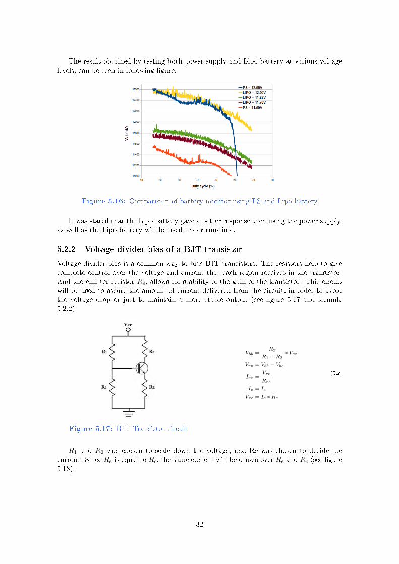
The result obtained by testing both power supply and Lipo battery at various voltagelevels, can be seen in following gure.
Figure 5.16: Comparision of battery monitor using PS and Lipo battery
It was stated that the Lipo battery gave a better response then using the power supply,as well as the Lipo battery will be used under run-time.
5.2.2 Voltage divider bias of a BJT transistor
Voltage divider bias is a common way to bias BJT transistors. The resistors help to givecomplete control over the voltage and current that each region receives in the transistor.And the emitter resistor Re, allows for stability of the gain of the transistor. This circuitwill be used to assure the amount of current delivered from the circuit, in order to avoidthe voltage drop or just to maintain a more stable output (see gure 5.17 and formula5.2.2).
Figure 5.17: BJT Transistor circuit
Vbb =R2
R1 +R2∗ Vcc
Vre = Vbb − Vbe
Ire =Vre
Rre
Ie = Ic
Vrc = Ic ∗Rc
(5.2)
R1 and R2 was chosen to scale down the voltage, and Re was chosen to decide thecurrent. Since Re is equal to Rc, the same current will be drawn over Re and Rc (see gure5.18).
32
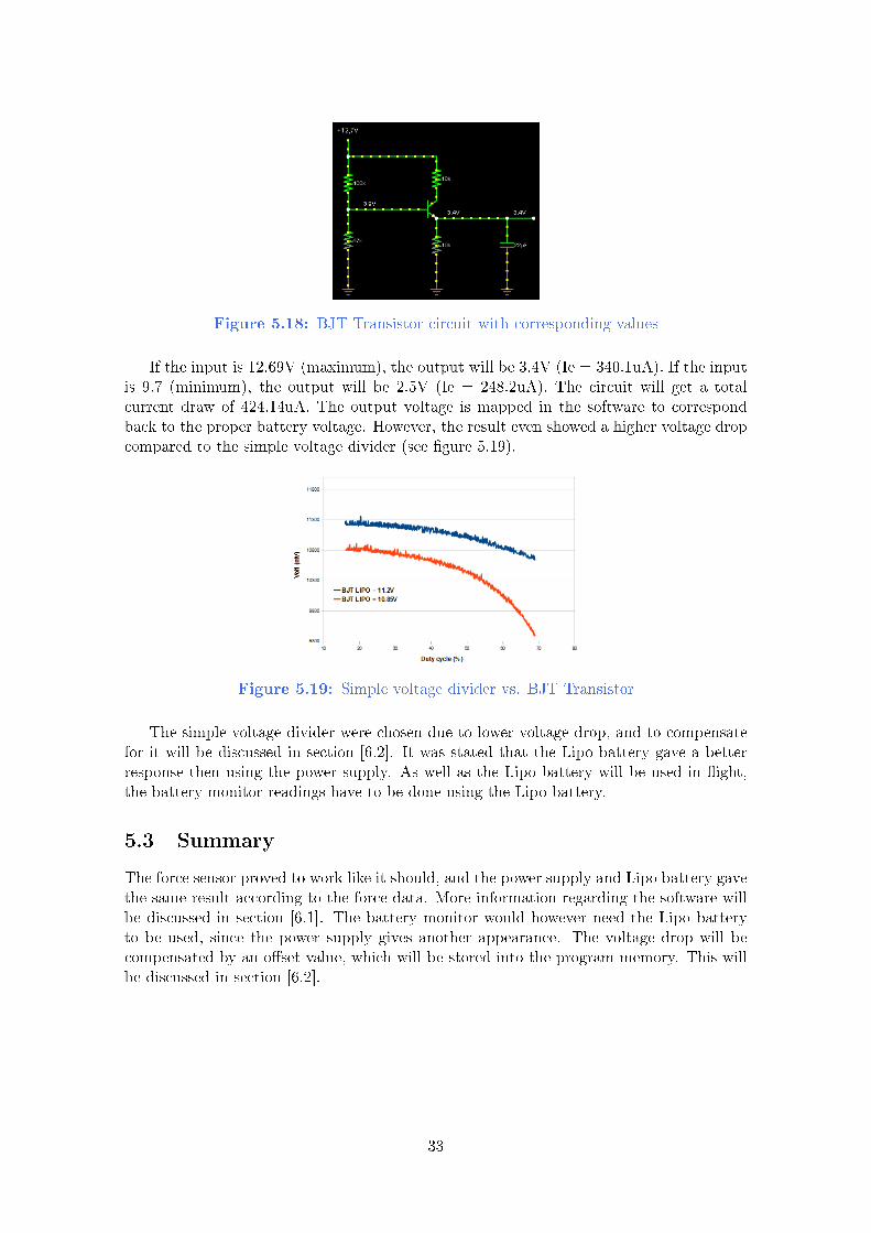
Figure 5.18: BJT Transistor circuit with corresponding values
If the input is 12.69V (maximum), the output will be 3.4V (Ie = 340.1uA). If the inputis 9.7 (minimum), the output will be 2.5V (Ie = 248.2uA). The circuit will get a totalcurrent draw of 424.14uA. The output voltage is mapped in the software to correspondback to the proper battery voltage. However, the result even showed a higher voltage dropcompared to the simple voltage divider (see gure 5.19).
Figure 5.19: Simple voltage divider vs. BJT Transistor
The simple voltage divider were chosen due to lower voltage drop, and to compensatefor it will be discussed in section [6.2]. It was stated that the Lipo battery gave a betterresponse then using the power supply. As well as the Lipo battery will be used in ight,the battery monitor readings have to be done using the Lipo battery.
5.3 Summary
The force sensor proved to work like it should, and the power supply and Lipo battery gavethe same result according to the force data. More information regarding the software willbe discussed in section [6.1]. The battery monitor would however need the Lipo batteryto be used, since the power supply gives another appearance. The voltage drop will becompensated by an oset value, which will be stored into the program memory. This willbe discussed in section [6.2].
33

6 | Software method
This section will present how force and battery monitor data is calculated on the Arduino Software
Development Kit. It will also give a solution on how to compensate for the voltage drop, and
present approaches on how to adjust the force command with help of the battery monitor. At last,
a description of the programs that were implemented will be presented, one which gather and store
the data and another program which reads and run the data. In the read and run program, the
selected approach for force curve adjustment will be implemented.
6.1 Read analog inputs from Arduino
The equation which was found for the load cell was f(x) = 0, 7x−150, 46. The equationwas implemented to the software and the result was inspected at dierent pressure levelson the load cell. The equation was further improved by modifying it to f(x) = 0, 75x−156,see source code in [G.1]. The load cell is connected to the analog input of (AN0), whereone value of the 12-bits ADC corresponds to 4.887585 mV. The x-values are rst sorted inan array of 201 values, before the median is selected and calculated in the above equation.Since the load cell is operating in a linear manner, the "y-intersection" can freely be changedwithout aecting the slope of the equation. The software is divided into two phases, wherethe rst phase reads the weight in the down direction, to get how many grams are puttedon the load cell. When the load cell is calibrated ('c' is pressed) regarding a well knownweight (asked for user input) of the motor and propeller combination exclusive the weight ofthe perpendicular plate, the program jumps into the second phase. On the second phase,the equation is zerolized (putted to zero) and starts to read the weight in the upwarddirection to get the response of force. Here it does not matter how the y-intersection havebeen changed from the rst phase, since the equation works in a linear manner. The mainformula, which is calculated in every iteration, is following.
valueEkv = 0.75*value - 156 CALIBRATION_VALUE;
And the rst phase where calibration is done, is calculated as following.
valueGramsInt = abs(valueEkv) START_WEIGHT;
Where START_WEIGHT is the weight for the perpendicular plate. The calibrationis calculated as following.
CALIBRATION_VALUE = CALIB_WEIGHT + START_WEIGHT + valueEkv + CALIBRATION_VALUE;
Where CALIB_WEIGHT is the motor and propeller weight. The second phase, afterit been zerolized is calculated following.
valueGramsInt = valueEkv + ZEROLIZE_VALUE;
Where ZEROLIZE_VALUE is the inverted value of valueEkv, to start the readingsfrom zero.
The battery monitor is connected to (AN1). These values are converted into millivoltaccording to the ADC, and sorted in an array of 101 values before the median is selected.The median value are later used in a map function, to transfer the range from the ADC(5V) to the actual battery voltage (see following code snippet for map function).
34

long map(long x, long in_min, long in_max, long out_min, long out_max)
return (x - in_min) * (out_max - out_min) / (in_max - in_min) + out_min;
Where long out_max is determined to what the maximum analog output of 5V wouldcorrespond to battery voltage input. According to formula 6.1, the output (and longout_max ) is calculated to be 15.638V.
Vout =R2
R1 +R2Vin => Vin =
R1 +R2
R2Vout =
100 kOhm+ 47 kOhm
47 kOhm5V = 15, 638V
(6.1)
6.2 Compensate for the battery monitor
It was stated that voltage divider was a better choice. One problem is the voltage drop,which occurs as higher PWM-signals are sent to the ESC. As it can be seen in gure 6.1,the voltage have dropped to 10.8V while the actual voltage of the battery is 11.35V.
Figure 6.1: Battery voltage drop
The read curve was achieved by reading the Lipo battery before and after the gatheringphase. The blue curve is the battery monitor data read in Arduino. In order to avoid thevoltage drop, it was proposed that it could be compensated for in the software. This meansthat instead of storing the values of the blue curve, the values of the orange oset arrowswill be stored (see gure 6.2).
Figure 6.2: Battery voltage compensation
Since the memory is limited, as well as the battery values are somehow jumpy, the datais going to be divided to make an average between every increment of 40 PWM-values inorder to smooth out the data. The oset values are now the red lines (see gure 6.3).
35

Figure 6.3: Battery voltage compensation with oset values
Every time the battery monitor is read, the oset value will be added to the currentbattery voltage depending on the PWM-signal sent last time. As higher PWM-signal thatwas sent, as higher oset will be added.
6.3 Force curve adjustment
There were several approaches for adjusting the force command regarding the currentbattery voltage. The rst option was to make a reading of the force curve and the batterymonitor at the same time, with use of the Lipo battery. The second option was to maketwo readings of the force curve, one with a Lipo battery and one with a power supply,which would be easier for adjusting the voltage. Or make two readings using the Lipobattery, but then the voltage would have to be drained a bit.
In the rst option, a pre-determined behaviour of the force curve at dierent voltagelevels had to be done. This can be achieved by testing the actuator at dierent voltagelevels and hard-code the behaviour into the software. One disadvantages though, is that itgets very specied to the specic actuator line used. A more dynamic approach is optiontwo, where everything can be calculated in the software under run-time. It will requiremore of the EEPROM memory, but it will be enough for this task. The second option havethree sub-options (see gure 6.4, 6.5, 6.6) in which every time a force command is sent tothe Force-PWM controller, some things needs to be calculated.
Option 2.1.)
Figure 6.4: Force curve adjustment opt. 2.1
Compare the dierence between the two force curves, in the certain force to be appliedand subtract or add it according to what the battery level is. Where ∆x = x2 − x1 is thedierence when the desired force is for example 400g.
Option 2.2.)
36

Figure 6.5: Force curve adjustment opt. 2.3
Calculate "x" and "b" degrees to the x-axis of the two lines which are pointing to thedesired force we want to apply, to get "how many degrees are changed per volt". Use thedegree to rotate the initial line (in this example "x") around the z-axis using a transforma-tion matrix, with a degree of rotation depending on what the battery monitor says. Thennd the right PWM-signal according to the rotated line. This approach is more dynamic,since the new lines will change according to the desired force to be applied as well as ofthe battery value.
Option 2.3.)
Figure 6.6: Force curve adjustment opt. 3
This approach would be to use an constant line for the initial force curve, and notchange it under run-time. The line can be rotated depending on the battery value as inthe previous option, and with use of an oset value (the red line with the pile), it canbe subtracted before the rotation and added again after the rotation. One disadvantageis that the blue line (the linear approximation) have to be found as near the initial forcecurve as possible for best result. The nal option which was chosen for the task was option2.1, as that would be easiest to implement and seemed to be most reliable.
6.4 Gather and store data in Arduino
A program was made called "Gather and Store" [G.1], which gather and stores each motor'sforce output. The x-values are ltered in a mean equation of 201 arrays-values, before themidpoint value is selected. Arduino Mega2560 provides an EEPROM size of 4096 byteswhich means it can store 4096 numbers with a range of 0-255 values. According to thedatasheet chapter 8.3 [F], the EEPROM is good for 100,000 read/write cycles. This meansthat each memory address can be read or write around 100,000 times, until the memory gets
37

damaged. The limitation of reading together with the memory size, limits the project'sexpectations. The data is therefore only stored once, and read once every start into atemporary buer. The data has also to be crypt in order to t 0-255 values and be storedinto the EEPROM. By using the inbuilt EEPROM library, it is possible to write and readaccordingly.
EEPROM.write(a,b);
z = EEPROM.read(a);
Where "a" is the number of row from 0-4096, "b" is the byte to be stored and "z" isthe byte to be read. A test was made using T-motor KV1100 and APC 9x4.7 at dierentvoltage levels using a power supply, to get the dierence in force output, while non of thesecurves was stored into the memory (see gure 6.7). The PWM-data data is dened from1000-2000 values, while the most interesting area lies between 1080-1680 of PWM-signals,8-68% of duty cycle, and around 300 grams of force.
Figure 6.7: Interesting area of force data
According to gure 6.7, the maximum force is 500g with 12.5V supply. This meansthat 500 values of force is going to be stored for every motor. To store and use the datafor two force curves, together with the battery monitor, the address places for the memoryare divided accordingly (see table 6.1).
To be stored Address places (1024)
Start voltage 11st force curve 500Battery monitor 500/400 = 12.5 ≈ 13Start voltage 1
2nd force curve 500Total 1015
Table 6.1: Address places divided in EEPROM
Since every force value on the force curve may not be dened from the gathering phase,the program will take the two nearest PWM-values and make an average in a lter function[G.2]. The second force curve will only be used to get the distance ∆x from gure 6.6, ata certain force to be applied. The nal data to be stored for motor one, can be seen infollowing table 6.2.
38

Address place Data Value
0 (M0) Start voltage(1) Volt1 (M0) Force(1) 1 PWM. . .
500 (M0) Force(1) 500 PWM501 (M0) Batt mon 1 O. Volt. . .
513 (M0) Batt mon 13 O. Volt514 (M0) Start voltage(2) Volt515 (M0) Force(2) 1 PWM. . .
1015 (M0) Force(2) 500 PWM. . .. . .
1024 (M1) Start voltage Volt1025 (M1) Force(1) 1 PWM. . .
Table 6.2: Data divided in EEPROM
Where the three remaining motors follows the same division, having the same intervalof 1024 address places. Motor 0 starts at 0, motor 1 at 1024, motor 2 at 2048 and motor 3at 3072. Before the data is stored into the memory, it has to be ltered and xed regardingthe requirements already stated in this project. The program ow for gather and storedata can be seen in gure 6.8.
Figure 6.8: Program ow for Gather and Store
When option 1 is pressed from "First or second?", the rst force curve will be storedtogether with the battery values to the corresponding memory place. When two is pressed,the second force curve will be stored. In both of the options, the data needs to be encryptedin order to be placed into the memory. The technique for encrypting the data can be seen
39

in [G.3]. The same technique is used to decrypt the data back to normal script and canbe seen in [H.2]. In "Filter function", the force data is averaged in function lterForce()and the battery oset compensation is done in function lterBattery(). A block diagramof the battery oset compensation can be seen in following gure.
Figure 6.9: Program ow for battery compensation
The battery array (1) of at least 500 values are summed up for every increment of indexpointer (corresponding to the PWM-signal), until 40 values have been summed together(2). The average of the 40 battery values are calculated (3) and if 13 values (n) have beengathered (4), the remaining oset values are found by taking the rst place of the averagearray subtracted by the remaining average values in a loop (5). The rst iteration of 40index increments Average[0] becomes the start voltage value for the actual force curve aswell.
6.5 Force-PWM controller
A program was made called "Read and Run" [H.1], which reads data from the EEPROM[H.2] to store it in the temporary motor structs. The motor struct contains all necessaryinformation, specic for every motor, to be used in the Force-PWM controller under run-time. See the following code snippet concerning variables inside the motor struct.
typedef struct my_motor_struct
// constants
int motor_number;
int first_start_value;
unsigned char first_force[NR_EEPROM_FORCE_DATA];
int first_force_index;
unsigned char first_battery[NR_EEPROM_BATTERY_DATA];
int first_battery_index;
int second_start_value;
unsigned char second_force[NR_EEPROM_FORCE_DATA];
int second_force_index;
// force pwm-controller, non-constants
int last_pwm;
int force_number_ctr;
double force_x_sum;
40

double force_x_result;
int first_offset;
int second_offset;
motor_struct;
The procedure for the Force-PWM controller yield the same theoretical approach pre-sented in section [6.3], and the implemented code can be seen in [H.3] for a more detailedexplanation. When the battery voltage is read, the Force-PWM controller make sure thecorresponding oset value is added depending on the last PWM-signal sent, to compen-sate for the voltage drop. The dierence between the two force curves are calculated atthe desired force, to get how many PWM-signals are changed per volt (PWM/Volt). Thedierence between the rst force curve (which was gathered by the Lipo battery) and thecurrent battery voltage is multiplied together with the calculated rate of PWM/Volt toestimate how much the PWM-signal has to be either added or subtracted from the rstforce curve. The distance is later added to the rst force curve to estimate the desiredPWM-signal as output from the Force-PWM controller.
6.6 Summary
The battery monitor is going to be compensated in an interval of every 40 PWM-value,in order to smooth out the data and save memory place. The force curves are going tobe read twice, to work as a force curve adjustment. Arduinos internal EEPROM wasproved to limit the amount of data to be stored, and only be capable of read/write 100,000times before it got damaged. The force and battery monitor data is therefore only writtenonce when gathered, and read once every start-up of the program. Two programs wereimplemented, one which gather and store the data, and another program which readsand run the memory data to control the quadrocopter. Some experiments regarding thesystem will be explained in section [7], including the Force-PWM controller to be testedboth theoretically and practically.
41

7 | Experiments
This section will explain how force changes over time using either Lipo battery or power supply. For
example, one may think that the heat on the motor generated by running longer times, minimizes the
force eect. The Lipo battery's theoretical discharge rate is compared to the practical measurement.
Dierent motors and propellers are going to be tested and compared to each other. The stored force
curves on the quadrocopter are going to be presented, as well as the output from the Force-PWM
controller when running the motors.
7.1 Force eect over time
The delivered current from the power supply, is proportional to the PWM-signal sentfrom the ESC. Since it is not possible to measure the current from the ESC to the motor(because of the current which goes back and forth) a measurement of the current was doneby connecting a multimeter between the power supply and ESC (see gure 7.1).
Figure 7.1: Current to force relation
The force curve is the data read from the load cell. The relation between force andcurrent yields over time (see gure 7.2).
Figure 7.2: Current and force over time
No obvious force or current dierence was observed by running the motor from coldstart to 10 min. Though when running normally, small variations of 20-30mA was foundwhich aected the force 2-3g. The force was further investigated over time, using the Lipobattery. By adjusting the PWM-signal to achieve 400g respective 300g of force, with 11.2Vrespective 12.35V, the following gure could be obtained.
42

Figure 7.3: Force line at 400g and 300g over time
As it can be seen, the two force curves are decreasing in a linear and parallel manner.After 16 minutes, the blue curve have dropped to 373g and the red to 272g. This gives anaverage decrease of 1.72g/min. The blue line says the battery have dropped 31.25mV andthe red 43,75mV. According to formula 2.1.2, the theoretical discharge rate was 282mV/minwith 4A load. The blue line starts with 4.55A and the red with 2.92A. The same formula2.1.2, gives that the red line discharges 200mV/min and the blue 280mV/min, which iseven lower then the theoretical even though it has 0.55A higher current.
7.2 Compare motor and propeller
To investigate any motor to motor variation, two motors were tested with the same modeland brand. Using the same actuator used on Iqarus quadrocopter, T-motor KV1100 andAPC 9x4.7, the result can be seen in following gure.
Figure 7.4: Dierence between two motors
To achieve the dierence in force between two dierent motors with three dierentpropellers, another test was made. The two motors were T-motor KV1100 (MT2208) andKV900 (MT2216-11), and the propellers APC 9x4.7, 10x3.8 and 11x4.7. The voltage wasset to 12V using a power supply. The result can be seen in following gure.
43

Figure 7.5: Dierence between two motors and three propellers
Motor MT2208 shows a better result compared to motor MT2216-11 using these pro-pellers, as it can be seen from the non-linearity and jumpy values. The smallest propeller9x4.7 (blue line) have not been declared in the datasheet of MT2216-11 [D], and by ob-serving the curve it may be the reason for the choice.
7.3 Testing the software
Two force curves and battery monitor data was gathered for each actuator line, and storedinto the EEPROM. A gure of the four rst force curves which been stored can be seen infollowing gure.
Figure 7.6: Four rst force curves to be stored
The x-axis shows PWM-signal since it directly corresponds to the force and PWM-signal relation dened from the EEPROM. The data is later ltered, to get each force from0-500g to represent a value of PWM-signal. A comparison of the original and ltered forcecurve can be seen in following gure.
44

Figure 7.7: Filtered force curve vs. Original
When gathering the data, the battery monitor oset values are added to the currentbattery value and the result can be seen in following gure.
Figure 7.8: Resulting battery voltage (red line)
Under run-time for motor 0 (see gure 7.9), the battery monitor is read (yellow line)and the oset values are added (blue line). The program make an average (red line) of theadded oset values under run-time.
Figure 7.9: Resulting battery voltage (redline) under run-time
Figure 7.10: First, second and estimatedforce curve
45

The corresponding force curves, can be seen to the right (see gure 7.10). The estimatedforce curve (yellow curve) is shown, together with the rst force curve (blue curve) andthe second force curve (red curve). Because of some disturbance when reading the batteryvoltage, the desired PWM-signal is summed during ve iterations through the Force-PWMcontroller. This to smooth out the result of the desired PWM-signal, and by not changingit as frequently. The result of using the Force-PWM controller to estimate the desiredPWM-signal for each motor under run time, can be seen in following gure.
Figure 7.11: Four motors with 1st and 2nd force curves
The dierence between the four desired PWM-signal lines which came out from theprevious gure (yellow curves), can be seen in following gure.
Figure 7.12: The four desired PWM-signals
46

7.4 Testing the lift-o phase
The aim of this test is to verify if the software manage to deliver equal amount of forcefor every specic actuator used on the quadrocopter, in order to y right upwards. Onthe Iqarus quadrocopter, the lift-o phase was used together with a stabilisation controller(PID-controller) with help of an IMU, in order to lift the quadropcopter until a certainheight was reached and the altitude controller was started. No stabilisation or altitudecontroller were implemented since that would require tests inside a net-cage, to be fullysure that it works. The goal of this experiment was just to test if the quadrocopter liftswithout any other control. The quadrocopter was therefore mounted to the ground withropes and the thrust for every actuator were increased in the same manner. See gure 7.13concerning the quadrocopter mounted with ropes to the oor.
Figure 7.13: Quadrocopter mounted to the oor
The result showed that the oset between the motors were avoided in the start bystarting at the same time (with dierent PWM-signals) and that it was possible to liftthe quadrocopter without any other control. What one has to think about, is to weightbalance the quadrocopter well and make sure the center of gravity remains the center ofthe quadrocopter since no stabilisation controller is used.
7.5 Summary
From what is observed, force and current curves have the same appearance. Using thepower supply does not eect the force over time and the Lipo battery remains to decreasein a linear manner. The result of comparing two motors with three propellers, showsthat the motors already used on Iqarus quadrocopter was the better choice. Testing thesoftware shows that the force curve adjustment managed to estimate and deliver the properamount of PWM-signal regarding the two force curves and the battery monitor. The lift-o phase was tested in practice and the result showed that no further controller had tobe implemented for lifting the quadrocopter, while some consideration had to be madeconcerning the weight balance in order to lift the quadrocopter right upwards.
47

8 | Analysing the Results
The result concerning the experiments from previous chapter are analysed. Questions such as why
is it better to control the actuators with force command rather than PWM-signal are going to be
answered, as well as how the result came out considering the expectations.
Why is it better to control the actuators with force rather than PWM-signal? Theforce control for the lift-o phase is surely a better approach, when not consider any otherimplemented control such as stabilisation and altitude control. In order to make a bettercontrol when ying, it was proposed that it would be better to look at the force producedfrom the actuator. The PWM-signal will in the end produce a force which aects thequadrocopter body and therefore the IMU-sensor, which in turn accumulates a new errorfrom the stabilisation controller to aect the motors again. To minimize the uncertaindierences when controlling the actuator, it seemed more sucient to let the controllerdirectly nd the right force needed, instead of adjusting the PWM-signal to the sameamount of force. By looking at the linear region of 200-300 grams of force from motor 3running at 13.10V (see gure 8.1).
Figure 8.1: Force of 200-300g at 13.10V Figure 8.2: Force of 200-300g at 11.35V
It is shown that one increment of PWM-signal is 1.19 times of the force produced.This means that the force command produced has a higher interval and accuracy than thePWM-signal control. Looking at the same motor running at 11.35V (see gure 8.2), it isshown that one increment of PWM-signal is 0.95 times of the force produced. This giveson the other hand, that the PWM-signal has a higher interval and accuracy than the forcecommand. The controller gain accuracy at voltages just above and higher than 11.35V,while loosing some accuracy when the battery falls below. On the third hand, concerningthe accuracy, it is also a question of how reliable the force sensor is constructed concerninggathering the correct force data. On the fourth hand, it is also essential that the batterymonitor represent the right amount of battery voltage with as small disturbance as possible,in order for the Force-PWM controller to estimate the proper PWM-signal. The bottomline, even though the result proved to be reliable concerning the experiments (gure 7.11)and the lift-o phase, some further work such as implementing the stabilisation controllerwould be necessary to determine if this approach really is a better approach than theprevious PWM-signal control, considering the ight.
48

9 | Summary and Conclusion
This section will review parts from the problem description and explain every problem that was
encountered and how it was solved.
To be able to get the actual performance of the actuator a force sensor needed to befound, such that it could gather the force produced by running the actuator. The datawould need to be stored on the control board of Arduino, from where the PWM-signalsare sent. Such force sensor was found to be a Vetek single point load cell 1kg, which is aaluminium construction using aWheatstone bridge with four strain-gauge sensors to outputthe dierence between them, when the material is getting bent. Since the deformationof the material is signicantly small and the analog signal is too low to establish anyreasonable output, the signal needs to be amplied using an Instrumentation AmplierINA125P. The circuit had to be constructed and designed using resistors, capacitors andtransistors, and the amplication was set to be 976 times of the original signal. A lot of EMIwere interfering the result, and by using decoupling and single capacitors, good shieldingand earth plan as well as twinning and placement of cables, third-ordered LP-lter on theoutput, the interference were avoided.
The force sensor had to be calibrated using well known weights, in order to get theright equation to be implemented on the software of Arduino. The project was providedwith the choice of using on of the two types of microcontrollers, either Arduino Mega2560or Arduino Due. After a comparison, it was stated that Arduino Mega2560 was the betterchoice. Oset and gain resistors on the circuit for INA125P were tested against each otherto nd a suitable range for the force data. The software delay time between each incrementof PWM-signal was compared to the settling time of using a third-ordered LP-lter on theoutput, to achieve the proper signal of force. Since the battery voltage directly aects theforce, a battery monitor had to be implemented in order to control the actuators regardingforce commands. Since the readable battery voltage drops as higher current is delivered,a voltage compensation had to been made in the software. A simple voltage divider wascompared with a circuit using a BJT transistor, with dierent values of resistors andcapacitors, in order to nd the most suitable output with as small voltage drop as possible.The nal battery monitor was chosen to be a simple voltage divider with a third-orderedLP-lter on the output.
The dierence of using a Lipo battery and a power supply were investigated, in order tocompare the output and dierence in voltage drop. It was shown both of the power sourcesdid not gave the same appearance, so a Lipo battery had to be used. The Lipo battery isused for gathering the data in order to achieve the proper battery monitor data and theproper battery oset data for the voltage drop compensation. The force at two dierentvoltage levels had to be gathered in order to use the dierence between to estimate thenal PWM-signal, which corresponds to the proper amount of force at the current batteryvoltage. One gathering is therefore done by the Lipo battery and the other was done witha power supply, since both of the power sources gave the same output of force at a certainvoltage level.
Two programs were implemented, one which gathers the data from the force sensor bysending dierent PWM-signals in a loop [G.1]. When the gatherings are done, the result isltered to dene a PWM-signal for every value of force from 0-500g [G.2]. Because of thesize-limitation of Ardunios inbuilt EEPROM, the data had to be crypt in order to be storedinto the memory [G.3]. Another program was made for reading the EEPROM [H.1], re-crypt and restore the data [H.2] into a temporary motor struct buer, in order to run each
49

individual motor with the Force-PWM controller [H.3]. Dierent motors and propellerswere tested in order to get the dierence between them regarding force output. The forceeect was inspected over time, to see if any heat on the motor could aect the performancein terms of force or current, while it was not found to be the case. The battery voltage andcurrent over time were also inspected in order to get a practical measurement to comparewith a theoretical estimation. The system was later tested by using the battery monitorand force curve adjustment, to see how the program estimates the desired PWM-signal atthe desired force as input (see gure 7.11 and 7.12).
The system were also directly tested on the quadrocopter for the lift-o phase, bybinding the quadrocopter with ropes to the oor, to make sure it just could lift a smalldistance. The result proved to be good, while some further work (e.g implementing thestabilisation controller with new PID-settings) have to be done in order to really see ifthe Force-PWM control is a better approach compared to the simple PWM-signal control,considering the ight.
50
10 | Discussion and Future Work
This section includes a critical analysis of the work which been done, and about the problems which
were encountered but maybe not solved in the best way. Are there any alternative approaches and
what are the positive and negative aspect regarding this work. At last, a proposal for some future
work are going to be presented.
10.1 Discussion
The problems that were encountered during the project, were investigated for solutions andsolved in the most suitable way. There is always some further development that can bedone, and the biggest concern at this stage is the battery monitor, since it outputs somehowjumpy values. This strictly aects the PWM-oset that is added to the rst force curve toestimate the desired PWM-signal. Even though the PWM-oset is summarized to makean average through ve iterations in the Force-PWM controller, it is still important tohave the interference as small as possible to even get a better result. It would also be morebenecial if there was no voltage drop to compensate for, and a greater EEPROM memoryto store the battery monitor data. The voltage drop seems like an unavoidable problembecause of the power limitation of the power sources. Another approach for constructingthe battery monitor, which was never tried due to lack of component, would be to use alinear optocoupler IL300. The linear optocoupler can isolate the battery voltage side bytransferring the voltage into an infra-LED light to be captured by a photodiod on the otherside. Another approach would be to use a hall-eect sensor to sense the proper amountof current, and/or use it as a feedback controller to preserve the right amount of currenttogether with the force input command. Such hall-eect sensor that would be of interest,is ACS714 Current sensor with maximum ±5A and a sensitivity of 185mV/A. Regardingthe force curve adjustment, even though the force curves at dierent voltage levels seemto have the same linear ratio of change (PWM/Volt) at a certain force produced, it is not100% guaranteed that this is the case. This is more an estimation of what it should be, andto know if it is really the case is somehow hard to predict. The uncertainty comes togetherwith the interference of the battery monitor, as well as how reliable the force sensor isworking. Even though the force sensor managed to output the right amount of grams byputting well known weights. A limitation of the project was the size of available EEPROMon the Arduino, which limits the number of force and battery data to be stored, as well asprovoking the need for crypting the data. Another limitation was the power supply, whichcould just deliver a maximum current of 6.42A, which got around 500g of force, using apower source with 13V.
10.2 Future work
Some future work would be to get a more reliable battery monitor, to make it more stableand not to make the average every ve iteration, before it takes eect on the desired PWM-signal. Some other future work would involve to make the stabilisation controller (a newPID-controller), to contribute the error to the force rather than PWM-signal. An altitudecontroller with the proper PD-settings to also be mirrored to the force rather than PWM-signal. This can surely be made by testing it inside a net cage. Alternative approacheswould be to use a gimball such as in [6] (gure 2) or to use a test bench such as in [5]
51

(gure 41). Since this is a development of the Iqarus quadrocopter, this project can be ofhelp for the next-coming students working on the quadrocopter next time. Though, thelong time goal is to be used for other robotic applications and by developers, interested toknow more about the force to pwm relation of the actuator line and its dynamics.
52

Bibliography
[1] Jianwen Shao. Direct back emf detection method for sensorless brushless dc (bldc)motor drives. pages 49, September 2003.
[2] Project group. Project iqarus. pages 0151, January 2013.
[3] Muhammad Saad Shaikh. Quadcopter fuzzy ight controller. page 9, 2011.
[4] Peter O. Basta. Quad copter ight. pages 1819, 24, 3839 May 2012.
[5] Michael David Schmidt. Simulation and control of a quadrotor unmanned aerialvehicle. pages 5354, 7172, April 2011.
[6] Torsten Bertram Frank Homann, Niklas Goddemeier. Attitude estimation and con-trol of a quadrocopter. pages 10731075, October 2010.
[7] Eva Saadé Latorre. Propulsion system optimization for an unmanned lightweightquadrotor. pages 2023, 3544, June 2011.
[8] MStarlabs. Ziegler-nichols tuning rules for pid. http://www.mstarlabs.com/
control/znrule.html, 2013.
[9] Vedran Sikiric. Control of quadrocopter. pages 1523, 2008.
[10] Peter Corke Inkyu Sa. System identication, estimation and control for a cost eectiveopen-source quadcopter. pages 45, September 2011.
[11] Patrik Karlsson Daniel Silvén. Sensornger. pages 1011, 1617, 2009.
[12] Fahti Kocer Jasmir Hamza. Patient supervision. pages 68, June 2002.
53

Glossary
ADC Analog to Digital Converter
BDC Brushed Direct Current
BLDC Brushless Direct Current
CCW Counter Clockwise
CMBET Combined Momentum and Blade Geometry
COTS Commercial o the Shell
CW Clockwise
EEPROM Electrically Erasable Programmable Read-Only Memory
EMI Electromagnetic Interference
ESC Electronic Speed Controller
ESR Equivalent Series Resistance
FET Field Eect Transistor
IC Integrated Circuit
IMU Inertial Measurement Unit
INA Instrumentation Amplier
Lipo Lithum Polymer
PID Proportional Integral Derivative
PWM Pulse Width Modulation
RPM Revolutions Per Minute
54
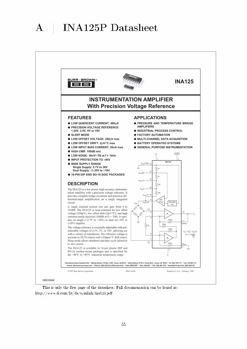
A | INA125P Datasheet
©1997 Burr-Brown Corporation PDS-1361B Printed in U.S.A., February, 1998
®
INA125
INSTRUMENTATION AMPLIFIER
With Precision Voltage Reference
FEATURES LOW QUIESCENT CURRENT: 460µA
PRECISION VOLTAGE REFERENCE:
1.24V, 2.5V, 5V or 10V
SLEEP MODE
LOW OFFSET VOLTAGE: 250µV max
LOW OFFSET DRIFT: 2µV/°C max
LOW INPUT BIAS CURRENT: 20nA max
HIGH CMR: 100dB min
LOW NOISE: 38nV/√ Hz at f = 1kHz
INPUT PROTECTION TO ±40V
WIDE SUPPLY RANGE
Single Supply: 2.7V to 36V
Dual Supply: ±1.35V to ±18V
16-PIN DIP AND SO-16 SOIC PACKAGES
APPLICATIONS PRESSURE AND TEMPERATURE BRIDGE
AMPLIFIERS
INDUSTRIAL PROCESS CONTROL
FACTORY AUTOMATION
MULTI-CHANNEL DATA ACQUISITION
BATTERY OPERATED SYSTEMS
GENERAL PURPOSE INSTRUMENTATION
DESCRIPTIONThe INA125 is a low power, high accuracy instrumen-
tation amplifier with a precision voltage reference. It
provides complete bridge excitation and precision dif-
ferential-input amplification on a single integrated
circuit.
A single external resistor sets any gain from 4 to
10,000. The INA125 is laser-trimmed for low offset
voltage (250µV), low offset drift (2µV/°C), and high
common-mode rejection (100dB at G = 100). It oper-
ates on single (+2.7V to +36V) or dual (±1.35V to
±18V) supplies.
The voltage reference is externally adjustable with pin-
selectable voltages of 2.5V, 5V, or 10V, allowing use
with a variety of transducers. The reference voltage is
accurate to ±0.5% (max) with ±35ppm/°C drift (max).
Sleep mode allows shutdown and duty cycle operation
to save power.
The INA125 is available in 16-pin plastic DIP and
SO-16 surface-mount packages and is specified for
the –40°C to +85°C industrial temperature range.
A1
Ref
Amp10V
A2
30kΩ
10kΩ
10kΩ
30kΩ
Bandgap
VREF
13
12
1
14
15
16
4
6
9
10
11
IAREF
5
8
7
RG
Sense
R
R
2R
4R
INA125VREFCOM
VREFBG
VREF2.5
VREF5
VREF10
VREFOut
VIN
V+
+
VIN–
2
SLEEP
3
V–
VO = (VIN – VIN) G
G = 4 + 60kΩ
+ –
RG
VO
INA125
INA125
International Airport Industrial Park • Mailing Address: PO Box 11400, Tucson, AZ 85734 • Street Address: 6730 S. Tucson Blvd., Tucson, AZ 85706 • Tel: (520) 746-1111 • Twx: 910-952-1111
Internet: http://www.burr-brown.com/ • FAXLine: (800) 548-6133 (US/Canada Only) • Cable: BBRCORP • Telex: 066-6491 • FAX: (520) 889-1510 • Immediate Product Info: (800) 548-6132
SBOS060
This is only the rst page of the datasheet. Full documentation can be found at:
http://www.ti.com/lit/ds/symlink/ina125.pdf
55
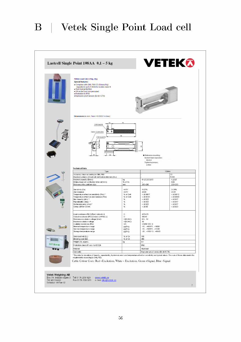
B | Vetek Single Point Load cell
56

C | T-motor KV1100 Datasheet
57
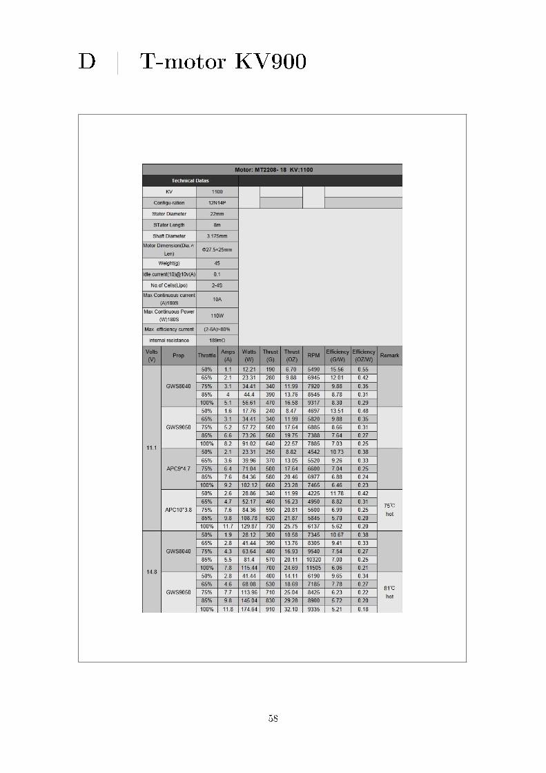
D | T-motor KV900
58

E | Arduino Mega2560 Rev3 Schematic
59

F | ATMEL Mega2560 Datasheet
This is only the rst page of the datasheet. Full documentation can be found at:
http://www.atmel.com/Images/doc2549.pdf
60
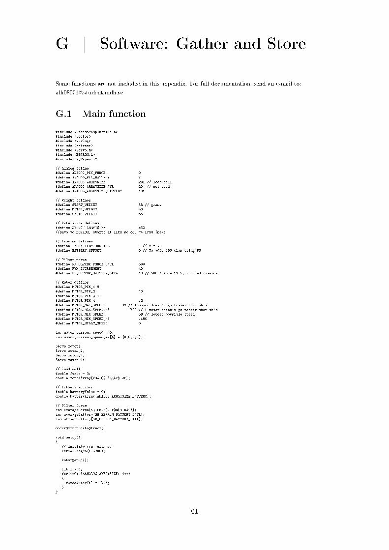
G | Software: Gather and Store
Some functions are not included in this appendix. For full documentation, send an e-mail to:
G.1 Main function
#include <StandardCplusplus.h>#include <vector>#include <string>#include <sstream>#include <Servo.h>#include <EEPROM.h>#include "MyTypes.h"
// Analog define#define ANALOG_PIN_FORCE 0#define ANALOG_PIN_BATTERY 7#define ANALOG_ARRAYSIZE 201 // load cell#define ANALOG_ARRAYSIZE_AVR 20 // not used#define ANALOG_ARRAYSIZE_BATTERY 101
// Weight defines#define START_WEIGHT 58 // grams#define MOTOR_WEIGHT 60#define CALIB_WEIGHT 65
// Data store defines#define STRUCT_ARRAYSIZE 530//Save to EEPROM, starts at 1160 so 540 => 1700 (max)
// Program defines#define IF_BATTERY_MONITOR 1 // 0 = NO#define BATTERY_OFFSET 0 // To add, 150 when using PS
// Filter force#define NR_EEPROM_FORCE_DATA 500#define PWM_INCREEMENT 40#define NR_EEPROM_BATTERY_DATA 13 // 500 / 40 = 12.5, rounded upwards
// Motor defines#define MOTOR_PIN_1 9#define MOTOR_PIN_2 10#define MOTOR_PIN_3 11#define MOTOR_PIN_4 12#define MOTOR_MAX_SPEED 88 // 1 motor doesn't go faster than this#define MOTOR_MAX_SPEED_MS 1700 // 1 motor doesn't go faster than this#define MOTOR_MIN_SPEED 58 // lowest possible speed#define MOTOR_MIN_SPEED_MS 1180#define MOTOR_START_SPEED 0
int motor_current_speed = 0;int motor_current_speed_ms[4] = 0,0,0,0;
Servo motor;Servo motor_2;Servo motor_3;Servo motor_4;
// Load celldouble force = 0;double forceArray[ANALOG_ARRAYSIZE];
// Battery monitordouble batteryValue = 0;double batteryArray[ANALOG_ARRAYSIZE_BATTERY];
// Filter forceint averageForce[NR_EEPROM_FORCE_DATA];int averageBattery[NR_EEPROM_BATTERY_DATA];int offsetBattery[NR_EEPROM_BATTERY_DATA];
motorStruct dataStruct;
void setup()
// initiate com. with pcSerial.begin(115200);
motorSetup();
int i = 0;for(i=0; i<ANALOG_ARRAYSIZE; i++)forceArray[i] = '\0';
61

void loop()
int incomingByte = 0;int i = 0, k = 0;double value = 0;double valueEkv = 0;int valueGramsInt = 0;double CALIBRATION_VALUE = 0;double ZEROLIZE_VALUE = 0;int structCtr = 0;int PHASE = 0;int motorNr = 0;int batteryValueInt=0;int forceNr=0;
yesOrNoText("Lets start the readings?");
while(1)
if (Serial.available() > 0) incomingByte = Serial.read();if (incomingByte == 'q')motorSetSpeed(motorNr, motor_current_speed_ms[motorNr] + 1);
else if (incomingByte == 'a')motorSetSpeed(motorNr, motor_current_speed_ms[motorNr] - 1);
else if (incomingByte == 'w')motorSetSpeed(motorNr, motor_current_speed_ms[motorNr] + 10);
else if (incomingByte == 's')motorSetSpeed(motorNr, motor_current_speed_ms[motorNr] - 10);
else if (incomingByte == 'e')motorSetSpeed(motorNr, motor_current_speed_ms[motorNr] + 50);
else if (incomingByte == 'd')motorSetSpeed(motorNr, motor_current_speed_ms[motorNr] - 50);
else if (incomingByte == 'r')motorSetSpeed(0, motor_current_speed_ms[motorNr] + 1);motorSetSpeed(1, motor_current_speed_ms[motorNr] + 1);motorSetSpeed(2, motor_current_speed_ms[motorNr] + 1);motorSetSpeed(3, motor_current_speed_ms[motorNr] + 1);
else if (incomingByte == 'f')motorSetSpeed(0, motor_current_speed_ms[motorNr] - 1);motorSetSpeed(1, motor_current_speed_ms[motorNr] - 1);motorSetSpeed(2, motor_current_speed_ms[motorNr] - 1);motorSetSpeed(3, motor_current_speed_ms[motorNr] - 1);
else if (incomingByte == 'c')Serial.print("To how many grams do you want to calibrate? ");CALIB_WEIGHT = readCalib();
Serial.print("***CALIBRATING WITH WEIGHT ");Serial.print(CALIB_WEIGHT);Serial.println("***");// how much the difference is to CALIB_WEIGHT, if positive, increase the valueCALIBRATION_VALUE = CALIB_WEIGHT + START_WEIGHT + valueEkv + CALIBRATION_VALUE;Serial.print("***OFFSET BECAME: ");Serial.print(CALIBRATION_VALUE);Serial.println("***");delay(1000);
else if (incomingByte == 'v')// How long is the value from zero// e.g -120g from zero => ZEROLIZED_VALUE = 120 to addZEROLIZE_VALUE = (-1)*valueEkv;Serial.print("***ZEROLIZING THE WEIGHT SCALE: ");Serial.print(ZEROLIZE_VALUE);Serial.println("***");delay(1000);PHASE = 1;
else if (incomingByte == 'b')// Start automatic reading force and store in structwhile(1)
// Stop whenever 'q' is pressedif (Serial.available() > 0)incomingByte = Serial.read();if (incomingByte == 'q')
break;else
;for(i=0; i<ANALOG_ARRAYSIZE; i++)force = analogRead(ANALOG_PIN_FORCE);forceArray[i] = force;
isort(forceArray, ANALOG_ARRAYSIZE);value = forceArray[ANALOG_ARRAYSIZE/2];Serial.print(" Midpoint: ");Serial.print(value);
valueEkv = 0.75*value - 156 - CALIBRATION_VALUE;valueGramsInt = valueEkv + abs(ZEROLIZE_VALUE);Serial.print(" Force: ");Serial.print(valueGramsInt);
62
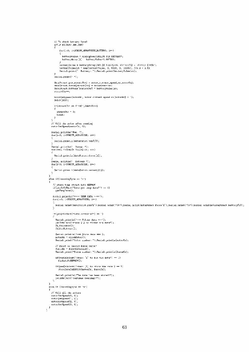
// To check battery levelif(IF_BATTERY_MONITOR)
for(i=0; i<ANALOG_ARRAYSIZE_BATTERY; i++)
batteryValue = analogRead(ANALOG_PIN_BATTERY);batteryArray[i] = batteryValue*4.887585;
batteryValue = batteryArray[ANALOG_ARRAYSIZE_BATTERY/2] - BATTERY_OFFSET;batteryValueInt = map(batteryValue, 0, 5000, 0, 16000); //3.3 + 1.5KSerial.print(" Battery: ");Serial.print(batteryValueInt);
Serial.print(" ");
dataStruct.pwm[structCtr] = motor_current_speed_ms[motorNr];dataStruct.force[structCtr] = valueGramsInt;dataStruct.battery[structCtr] = batteryValueInt;structCtr++;
motorSetSpeed(motorNr, motor_current_speed_ms[motorNr] + 1);delay(200);
if(structCtr == STRUCT_ARRAYSIZE)structCtr = 0;break;
// Kill the motor after readingmotorSetSpeed(motorNr, 0);
Serial.println("Pwm: ");for(i=0; i<STRUCT_ARRAYSIZE; i++)
Serial.println(dataStruct.pwm[i]);Serial.println(" Force: ");for(i=0; i<STRUCT_ARRAYSIZE; i++)
Serial.println(dataStruct.force[i]);Serial.println(" Battery ");for(i=0; i<STRUCT_ARRAYSIZE; i++)
Serial.println(dataStruct.battery[i]);
else if(incomingByte == 'n')
// store temp struct into EEPROMif(yesOrNoText("Lets get temp data?") == 1)
getTempData();
Serial.println("**** TEMP DATA ****");for(i=0; i<STRUCT_ARRAYSIZE; i++)
Serial.print(dataStruct.pwm[i]);Serial.print('\t');Serial.print(dataStruct.force[i]);Serial.print('\t');Serial.println(dataStruct.battery[i]);
if(yesOrNoText("Lets continue?") == 1)
Serial.println("*** Filter data ***");yesOrNoText("Press [1] to filter the data");filterForce();filterBattery();
Serial.println("*** Store data ***");motorNr = whichMotor();Serial.print("Motor number: ");Serial.println(motorNr);
// first or second force curve?forceNr = firstOrSecond();Serial.print("Force number: ");Serial.println(forceNr);
if(yesOrNoText("Press [1] to fix the data") == 1)fixDataToEEPROM();
if(yesOrNoText("Press [1] to store the data") == 1)storeDataToEEPROM(motorNr, forceNr);
Serial.println("The data has been stored!");yesOrNoText("Continue readings?");
else if (incomingByte == 'z')// Kill all the motorsmotorSetSpeed(0, 0);motorSetSpeed(1, 0);motorSetSpeed(2, 0);motorSetSpeed(3, 0);
63

for(i=0; i<ANALOG_ARRAYSIZE; i++)
force = analogRead(ANALOG_PIN_FORCE);forceArray[i] = force;
isort(forceArray, ANALOG_ARRAYSIZE);value = forceArray[ANALOG_ARRAYSIZE/2];
Serial.print(" Midpoint: ");Serial.print(value);
valueEkv = 0.75*value - 156 - CALIBRATION_VALUE;
if(PHASE == 0) // Phase 1
// force downwards, under calibrating and zerolizing, increased when pressed downvalueGramsInt = abs(valueEkv) - START_WEIGHT;
if(PHASE == 1) // Phase 2
// value zerolized, increase the value for the upward forcevalueGramsInt = valueEkv + ZEROLIZE_VALUE;
Serial.print(" Weight: ");Serial.print(valueGramsInt);
// Battery monitorif(IF_BATTERY_MONITOR)
for(i=0; i<ANALOG_ARRAYSIZE_BATTERY; i++)batteryValue = analogRead(ANALOG_PIN_BATTERY);batteryArray[i] = batteryValue*4.887585;
batteryValue = batteryArray[ANALOG_ARRAYSIZE_BATTERY/2] - BATTERY_OFFSET;batteryValueInt = map(batteryValue, 0, 5000, 0, 16000); // Volt div. of 3.3 + 1.5KSerial.print(" Battery: ");Serial.print(batteryValueInt);
Serial.print("Free ram: ");Serial.println(freeRam());
delay(20);
// while
G.2 Filter functions
void filterForce()
int i = 0;int localCounter = 0;double average = 0;int averageInt = 0;int maxForce = 0;int maxPWM = 0;
for(i=0; i<NR_EEPROM_FORCE_DATA; i++)
averageForce[i] = '\0';
averageForce[localCounter] = ((int)MOTOR_MIN_SPEED_MS-20); //= 1160localCounter++;
for(i=0; i<STRUCT_ARRAYSIZE; i++) // up to 530
Serial.print("dataStruct.force[i]: ");Serial.println(dataStruct.force[i]);
// Store max and min values (for interest)if(dataStruct.force[i] >= maxForce)maxForce = dataStruct.force[i];maxPWM = dataStruct.pwm[i];
if(dataStruct.force[i] == localCounter)// Found one right after one otheraverage = dataStruct.pwm[i];averageForce[localCounter] = (int)average;localCounter++;
else if(dataStruct.force[i] == (localCounter+1))// Average on the two latestaverage = ((dataStruct.pwm[(i-1)] + dataStruct.pwm[i])/2);averageForce[localCounter] = (int)average;
64

localCounter++;i--;
else if(dataStruct.force[i] == (localCounter+2))// Average on the two latestaverage = ((dataStruct.pwm[(i-1)] + dataStruct.pwm[i])/2);averageForce[localCounter] = (int)average;localCounter++;i--;
else if(dataStruct.force[i] == (localCounter+3))// Average on the two latestaverage = ((dataStruct.pwm[(i-1)] + dataStruct.pwm[i])/2);averageForce[localCounter] = (int)average;localCounter++;i--;
else if(dataStruct.force[i] == (localCounter+4))// Average on the two latestaverage = ((dataStruct.pwm[(i-1)] + dataStruct.pwm[i])/2);averageForce[localCounter] = (int)average;localCounter++;i--;
elseSerial.println("Error: Force difference bigger than 5..");
if(localCounter==NR_EEPROM_FORCE_DATA) //500Serial.println("break");break;
// Fixing the final values of the force array, to not be zerofor(i=0; i<NR_EEPROM_FORCE_DATA-1; i++)
if(averageForce[i+1] == 0)averageForce[i+1] = averageForce[i];
Serial.println("*** FILTERED FORCE ***");for(i=0; i<NR_EEPROM_FORCE_DATA; i++)
Serial.print(i);Serial.print(" ");Serial.println(averageForce[i]);Serial.print("Max PWM: ");Serial.print(maxPWM);Serial.print(" Max force: ");Serial.println(maxForce);delay(3);
void filterBattery()
int i = 0;int START = 0;int startPWM = 0;double sum = 0;int average = 0;int pwmCounter = 0;int localCounter = 0;
for(i=0; i<NR_EEPROM_BATTERY_DATA; i++)
averageBattery[i] = '\0';offsetBattery[i] = '\0';
// Divide the curve, and make an average of every divisionfor(i=0; i<STRUCT_ARRAYSIZE; i++) // upp till 500
if(dataStruct.force[i] > 0 && START == 0)START = 1;startPWM = dataStruct.pwm[i];Serial.print("Start PWM: ");Serial.println(startPWM);
if(START == 1)sum = sum + dataStruct.battery[i];pwmCounter++;
if(pwmCounter == PWM_INCREEMENT)
Serial.print("PWM: ");Serial.print(dataStruct.pwm[i]);average = (sum/pwmCounter);Serial.print(" Battery average: ");Serial.println(average);averageBattery[localCounter] = average;localCounter++;pwmCounter = 0;sum = 0;
65
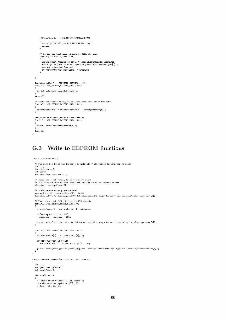
if(localCounter == NR_EEPROM_BATTERY_DATA)
Serial.println("**** FOR LOOP BREAK ****");break;
// Saving the last unsaved data to fill the arrayif((i+1) == STRUCT_ARRAYSIZE)
Serial.print("Number of data: ");Serial.println(localCounter);Serial.print("Finish PWM: ");Serial.println(dataStruct.pwm[i]);average = (sum/pwmCounter);averageBattery[localCounter] = average;
Serial.println("*** FILTERED BATTERY ***");for(i=0; i<NR_EEPROM_BATTERY_DATA; i++)
Serial.println(averageBattery[i]);delay(3);
// Store the offset value, to be added when read under run-timefor(i=0; i<NR_EEPROM_BATTERY_DATA; i++)
offsetBattery[i] = averageBattery[0] - averageBattery[i];
Serial.println("*** OFFSET BATTERY ***");for(i=0; i<NR_EEPROM_BATTERY_DATA; i++)
Serial.println(offsetBattery[i]);delay(3);
G.3 Write to EEPROM functions
void fixDataToEEPROM()
// Fix data for force and battery, to maintain 0-255 values in each adress placeint i=0;int minimize = 0;int ctr=0;unsigned char readChar = 0;
// Store the first value, to be the start point// Will also be used to know which PWM relates to which battery valuesminimize = averageForce[0];
// Minimize the first place by 1000averageForce[0] = averageForce[0] - 1000;Serial.print("i=");Serial.print("0");Serial.print("Average force: ");Serial.println(averageForce[0]);
// Take minus 1000+(255*n) from the PWM-signalsfor(i=1; i<NR_EEPROM_FORCE_DATA; i++)
averageForce[i] = averageForce[i] - minimize;
if(averageForce[i] >= 255)minimize = minimize + 255;
Serial.print("i=");Serial.print(i);Serial.print("Average force: ");Serial.println(averageForce[i]);
for(i=0; i<NR_EEPROM_BATTERY_DATA; i++)
offsetBattery[i] = offsetBattery[i]/10;
if(offsetBattery[i] >= 255)offsetBattery[i] = offsetBattery[i] - 255;
Serial.print("i=");Serial.print(i);Serial.print(" offsetBattery: ");Serial.println(offsetBattery[i]);
void storeDataToEEPROM(int motorNr, int forceNr)
int i=0;unsigned char myChar=0;int startValue=0;
if(forceNr == 1)
// Store start voltage: 0 (ex. motor 0)startValue = averageBattery[0]/100;myChar = startValue;
66

Serial.print("Start value: ");Serial.print((motorNr*1024));Serial.print(" ");Serial.println((int)myChar);EEPROM.write((motorNr*1024), myChar);
// Store force from: 1-500 (ex. motor 0)for(i=0; i<NR_EEPROM_FORCE_DATA; i++)myChar = (unsigned char)averageForce[i];Serial.print("Force1: ");Serial.print((i+1)+(motorNr*1024));Serial.print(" ");Serial.println((int)myChar);EEPROM.write(((i+1)+(motorNr*1024)), myChar);
// Store battery from: 501-513 (ex. motor 0)for(i=0; i<NR_EEPROM_BATTERY_DATA; i++)myChar = (unsigned char)offsetBattery[i];Serial.print("Batt: ");Serial.print((i+1)+(motorNr*1024)+NR_EEPROM_FORCE_DATA);Serial.print(" ");Serial.println((int)myChar);EEPROM.write(((i+1)+(motorNr*1024)+NR_EEPROM_FORCE_DATA), myChar);
else if(forceNr == 2)
// Store second start voltage: 514startValue = averageBattery[0]/100;myChar = startValue;Serial.print("Start value: ");Serial.print(1+(motorNr*1024)+NR_EEPROM_FORCE_DATA+NR_EEPROM_BATTERY_DATA);Serial.print(" ");Serial.println((int)myChar);EEPROM.write((1+(motorNr*1024)+NR_EEPROM_FORCE_DATA+NR_EEPROM_BATTERY_DATA), myChar);
// Store second force curve from 515-1015for(i=0; i<NR_EEPROM_FORCE_DATA; i++)myChar = (unsigned char)averageForce[i];Serial.print("Force2: ");Serial.print((i+2)+(motorNr*1024)+NR_EEPROM_FORCE_DATA+NR_EEPROM_BATTERY_DATA);Serial.print(" ");Serial.println((int)myChar);EEPROM.write(((i+2)+(motorNr*1024)+NR_EEPROM_FORCE_DATA+NR_EEPROM_BATTERY_DATA), myChar);
67

H | Software: Read and Run
Some functions are not included in this appendix. For full documentation, send an e-mail to:
H.1 Main function
#include <StandardCplusplus.h>#include <vector>#include <string>#include <sstream>#include <Servo.h>#include <EEPROM.h>#include "MyTypes.h"
#define STRUCT_ARRAYSIZE 530//Save to EEPROM, starts at 1160 so 540 => 1700 (max)
#define ANALOG_ARRAYSIZE_BATTERY 101#define ANALOG_PIN_BATTERY 7#define BATTERY_OFFSET 0
// filter force#define NR_EEPROM_FORCE_DATA 500#define PWM_INCREEMENT 40#define NR_EEPROM_BATTERY_DATA 13 // 500 / 40 = 12.5, rounded upwards
// motor defines#define MOTOR_PIN_1 9#define MOTOR_PIN_2 10#define MOTOR_PIN_3 11#define MOTOR_PIN_4 12#define MOTOR_MAX_SPEED 88 // 1 motor doesn't go faster than this#define MOTOR_MAX_SPEED_MS 1700 // 1 motor doesn't go faster than this#define MOTOR_MIN_SPEED 58 // lowest possible speed#define MOTOR_MIN_SPEED_MS 1180#define MOTOR_START_SPEED 0
//BATTERY MONITORdouble batteryValue = 0;double batteryArray[ANALOG_ARRAYSIZE_BATTERY];int batteryValueInt = 0;
int motor_current_speed = 0;int motor_current_speed_ms[4] = 0,0,0,0;int motor_increment = 1;Servo motor;Servo motor_2;Servo motor_3;Servo motor_4;
int FORCE_CURVE_ADJUSTMENT = 1; // 0 = NOint BATTERY_MONITOR = 1;
motor_struct m0struct, m1struct, m2struct, m3struct;
int M0Curr = 0;int M1Curr = 0;int M2Curr = 0;int M3Curr = 0;
void setup()// Setup com. with pcSerial.begin(115200);
// MotormotorSetup();
zerolizeCharStruct(&m0struct);zerolizeCharStruct(&m1struct);zerolizeCharStruct(&m2struct);zerolizeCharStruct(&m3struct);
void loop()
int incomingByte = 0;int i = 0;int motorNr = 0;int batteryValueInt = 0;
yesOrNoText("Lets start the program?");while(1)
if (Serial.available() > 0)
68

incomingByte = Serial.read();if (incomingByte == 'q')motorNr = whichMotor();if(motorNr == 0)
readCharDataFromEEPROM(&m0struct, motorNr);else if(motorNr == 1)
readCharDataFromEEPROM(&m1struct, motorNr);else if(motorNr == 2)
readCharDataFromEEPROM(&m2struct, motorNr);else if(motorNr == 3)
readCharDataFromEEPROM(&m3struct, motorNr);yesOrNoText("Continue readings?");
else if (incomingByte == 'w')motorNr = whichMotor();if(motorNr == 0)
printCharStruct(&m0struct);else if(motorNr == 1)
printCharStruct(&m1struct);else if(motorNr == 2)
printCharStruct(&m2struct);else if(motorNr == 3)
printCharStruct(&m3struct);yesOrNoText("Continue readings?");
else if (incomingByte == 'e')yesOrNoText("Motor by motor test");testMotorByMotor();
else if (incomingByte == 'r')yesOrNoText("Automatic lift-off phase");automaticLiftoff();
else if (incomingByte == 'z')// Kill all the motorsmotorSetSpeed(0, 0);motorSetSpeed(1, 0);motorSetSpeed(2, 0);motorSetSpeed(3, 0);
else if (incomingByte == 'x')yesOrNoText("Turn off/on Battery Monitor?");if(BATTERY_MONITOR == 0)
BATTERY_MONITOR = 1;else if(BATTERY_MONITOR == 1)
BATTERY_MONITOR = 0;Serial.print("BATTERY_MONITOR: ");Serial.println(BATTERY_MONITOR);
else if (incomingByte == 'c')yesOrNoText("Turn off/on Force Curve Adjustment?");if(FORCE_CURVE_ADJUSTMENT == 0)
FORCE_CURVE_ADJUSTMENT = 1;else if(FORCE_CURVE_ADJUSTMENT == 1)
FORCE_CURVE_ADJUSTMENT = 0;Serial.print("FORCE_CURVE_ADJUSTMENT: ");Serial.println(FORCE_CURVE_ADJUSTMENT);
batteryValueInt = batteryMonitor();Serial.print("Battery: ");Serial.print(batteryValueInt);Serial.print('\t');
Serial.print("Free ram: ");Serial.println(freeRam());
delay(300);
// while
H.2 Read from EEPROM function
void readCharDataFromEEPROM(struct my_motor_struct * ptr, int motorNr)
unsigned char readChar=0;int i=0;int myInt = 0;int maxInt = 0;int offset = 0;int check = 0;int index = 0;int index_check = 0;
ptr->motor_number = motorNr;Serial.print("*** Motor number ****: ");Serial.println(ptr->motor_number);
69

// Read first start voltage 0readChar = EEPROM.read(motorNr*1024);myInt = ((int)readChar)*100;ptr->first_start_value = myInt;Serial.print("Start value: ");Serial.print((motorNr*1024));Serial.print(" ");Serial.println(ptr->first_start_value);
// Read first start pwmreadChar = EEPROM.read(1+(motorNr*1024));myInt = ((int)readChar)+1000;ptr->last_pwm = myInt;Serial.print("Last pwm: ");Serial.print("0");Serial.print(" ");Serial.println(ptr->last_pwm);ptr->first_force[0] = (unsigned char)readChar;Serial.print("Start pwm: ");Serial.print("0");Serial.print(" ");Serial.println(ptr->first_force[0]);
// Read force from 1-500maxInt = 0;for(i=1; i<NR_EEPROM_FORCE_DATA; i++)
readChar = EEPROM.read((i+1)+(motorNr*1024));myInt = (int)readChar;ptr->first_force[i] = (unsigned char)readChar;
Serial.print("Force1: ");Serial.print(i);Serial.print(" ");Serial.println(ptr->first_force[i]);
if(myInt >= maxInt)maxInt = myInt;ptr->first_force_index = i;Serial.print("Index: ");Serial.print(ptr->first_force_index);Serial.print(" ");
// Read battery from 501-513 (Read and store, find max)maxInt = 0;for(i=0; i<NR_EEPROM_BATTERY_DATA; i++)
readChar = EEPROM.read((i+1)+(motorNr*1024)+NR_EEPROM_FORCE_DATA);myInt = (int)readChar;ptr->first_battery[i] = (unsigned char)readChar;
Serial.print("Batt1: ");Serial.print(i);Serial.print(" ");Serial.println(ptr->first_battery[i]);
if(myInt >= maxInt)maxInt = myInt;ptr->first_battery_index = i;Serial.print("Index: ");Serial.print(ptr->first_battery_index);Serial.print(" ");
// Read second start voltage 514readChar = EEPROM.read((1+(motorNr*1024)+NR_EEPROM_FORCE_DATA+NR_EEPROM_BATTERY_DATA));myInt = ((int)readChar)*100;ptr->second_start_value = myInt;Serial.print("Start value: ");Serial.print(0);Serial.print(" ");Serial.println(ptr->second_start_value);
// Read second start pwm 515readChar = EEPROM.read((2+(motorNr*1024)+NR_EEPROM_FORCE_DATA+NR_EEPROM_BATTERY_DATA));myInt = ((int)readChar)+1000;ptr->second_force[0] = (unsigned char)readChar;Serial.print("Start pwm: ");Serial.print(0);Serial.print(" ");Serial.println(ptr->second_force[0]);
// Read second force curve from 515-1014maxInt = 0;for(i=1; i<NR_EEPROM_FORCE_DATA; i++)
readChar = EEPROM.read((i+2)+(motorNr*1024)+NR_EEPROM_FORCE_DATA+NR_EEPROM_BATTERY_DATA);myInt = (int)readChar;ptr->second_force[i] = (unsigned char)readChar;
Serial.print("Force2: ");Serial.print(i);Serial.print(" ");Serial.println(ptr->second_force[i]);
if(myInt >= maxInt)maxInt = myInt;ptr->second_force_index = i;Serial.print("Index: ");Serial.print(ptr->second_force_index);Serial.print(" ");
H.3 Force-PWM Controller
int forcePwmController(struct my_motor_struct * ptr, int desiredForce)
if(BATTERY_MONITOR == 1)
// Calculate the index and check if its inbetween (0-13) (13*40 = 520)batteryIndex = ((ptr->last_pwm - (ptr->first_force[1]+(ptr->first_force[0]+1000)))/40);
70
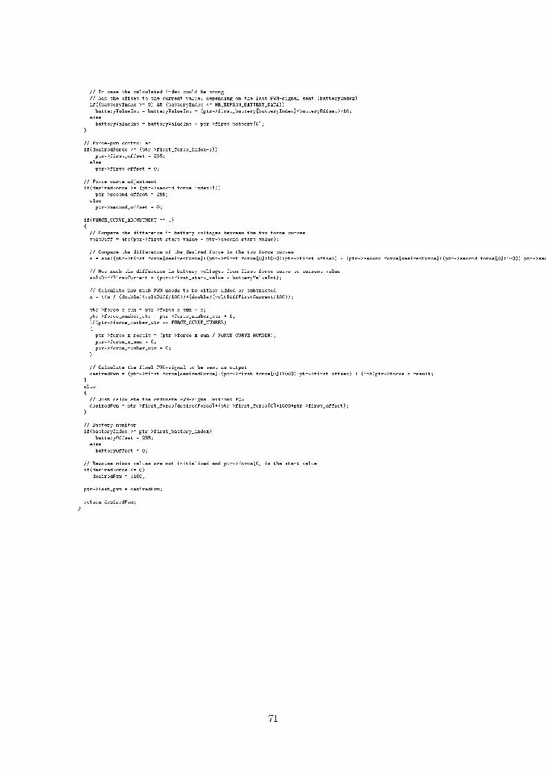
// In case the calculated index could be wrong// Add the offset to the current value, depending on the last PWM-signal sent (batteryIndex)if((batteryIndex >= 0) && (batteryIndex <= NR_EEPROM_BATTERY_DATA))batteryValueInt = batteryValueInt + (ptr->first_battery[batteryIndex]+batteryOffset)*10;
elsebatteryValueInt = batteryValueInt + ptr->first_battery[0];
// Force-pwm controllerif(desiredForce >= (ptr->first_force_index+1))
ptr->first_offset = 255;elseptr->first_offset = 0;
// Force curve adjustmentif(desiredForce >= (ptr->second_force_index+1))
ptr->second_offset = 255;elseptr->second_offset = 0;
if(FORCE_CURVE_ADJUSTMENT == 1)
// Compare the difference in battery voltages between the two force curvesvoltDiff = abs(ptr->first_start_value - ptr->second_start_value);
// Compare the difference of the desired force in the two force curvesa = abs((ptr->first_force[desiredForce]+(ptr->first_force[0]+1000)+ptr->first_offset) - (ptr->second_force[desiredForce]+(ptr->second_force[0]+1000)+ptr->second_offset));
// How much the difference in battery voltages from first force curve to current valuevoltDiffFirstCurrent = (ptr->first_start_value - batteryValueInt);
// Calculate how much PWM needs to be either added or subtractedx = ((a / (double)(voltDiff/100))*(double)(voltDiffFirstCurrent/100));
ptr->force_x_sum = ptr->force_x_sum + x;ptr->force_number_ctr = ptr->force_number_ctr + 1;if(ptr->force_number_ctr == FORCE_CURVE_NUMBER)ptr->force_x_result = (ptr->force_x_sum / FORCE_CURVE_NUMBER);ptr->force_x_sum = 0;ptr->force_number_ctr = 0;
// Calculate the final PWM-signal to be sent as outputdesiredPwm = (ptr->first_force[desiredForce]+(ptr->first_force[0]+1000)+ptr->first_offset) + (int)ptr->force_x_result;
else
// Just calculate the ordinare PWM-signal without FCAdesiredPwm = ptr->first_force[desiredForce]+(ptr->first_force[0]+1000+ptr->first_offset);
// Battery monitorif(batteryIndex >= ptr->first_battery_index)
batteryOffset = 255;elsebatteryOffset = 0;
// Because minus values are not initialized and ptr->force[0] is the start valueif(desiredForce <= 0)
desiredPwm = 1160;
ptr->last_pwm = desiredPwm;
return desiredPwm;
71