Embed Size (px)
Citation preview
Michael David Bryant 10/11/07 ME 392Q Mechatronics 1 University of Texas at Austin 4
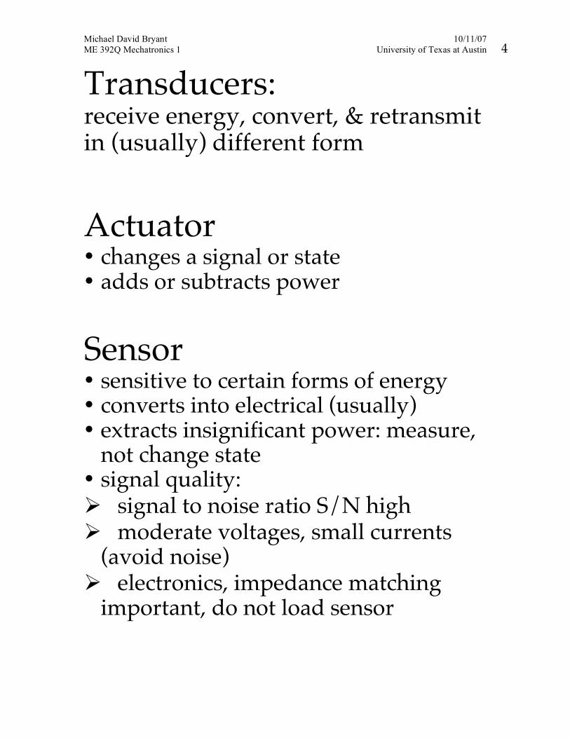
Transducers: receive energy, convert, & retransmit in (usually) different form
Actuator • changes a signal or state • adds or subtracts power
Sensor • sensitive to certain forms of energy • converts into electrical (usually) • extracts insignificant power: measure,
not change state • signal quality: signal to noise ratio S/N high moderate voltages, small currents
(avoid noise) electronics, impedance matching
important, do not load sensor
Michael David Bryant 10/11/07 ME 392Q Mechatronics 1 University of Texas at Austin 5
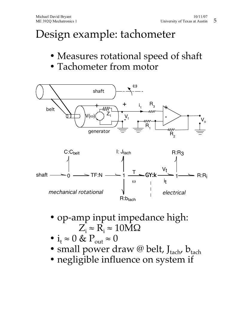
Design example: tachometer
• Measures rotational speed of shaft • Tachometer from motor
shaft
ω
generator
belt +-
1R
2R
3R
tV
ti+
- oVV(ω)
+
- tZ
0 TF:N 1
I: Jtach
!
shaft
R:btach
GY:kT
1
R:R3
electricalmechanical rotational
C:Cbelt
Vt
it
R:Ri
• op-amp input impedance high: Zi ≈ Ri ≈ 10MΩ
• it ≈ 0 & Pout ≈ 0 • small power draw @ belt, Jtach, btach • negligible influence on system if
Michael David Bryant 10/19/06 ME 392Q Mechatronics 1 University of Texas at Austin 1
SENSORS & MEASUREMENTS • Measurement: Comparison of a specimen to a
standard, within some agreed upon reference frame. o A successful measurement must maintain (i.e.,
apply controls to) specimen, standard, and a stable reference frame.
o All measurements based on standard. o Maintenance of standards & reference frame
critical to any measurement • Measurement process: Compare specimen to standard. Errors can arise from variations in
o specimen o standard o reference frame o comparison process
Michael David Bryant 10/19/06 ME 392Q Mechatronics 1 University of Texas at Austin 2
SI Measurement System 7 Basic quantities o Length o Mass o Temperature o Time o Luminous intensity o Amount of substance (moles) o Electric current
Michael David Bryant 10/19/06 ME 392Q Mechatronics 1 University of Texas at Austin 3
• Measurements for mechatronics: o Position o Displacement o Velocity o Force o Torque o Angles o Time o Pressure o Temperature o Flows o Power
Transducers
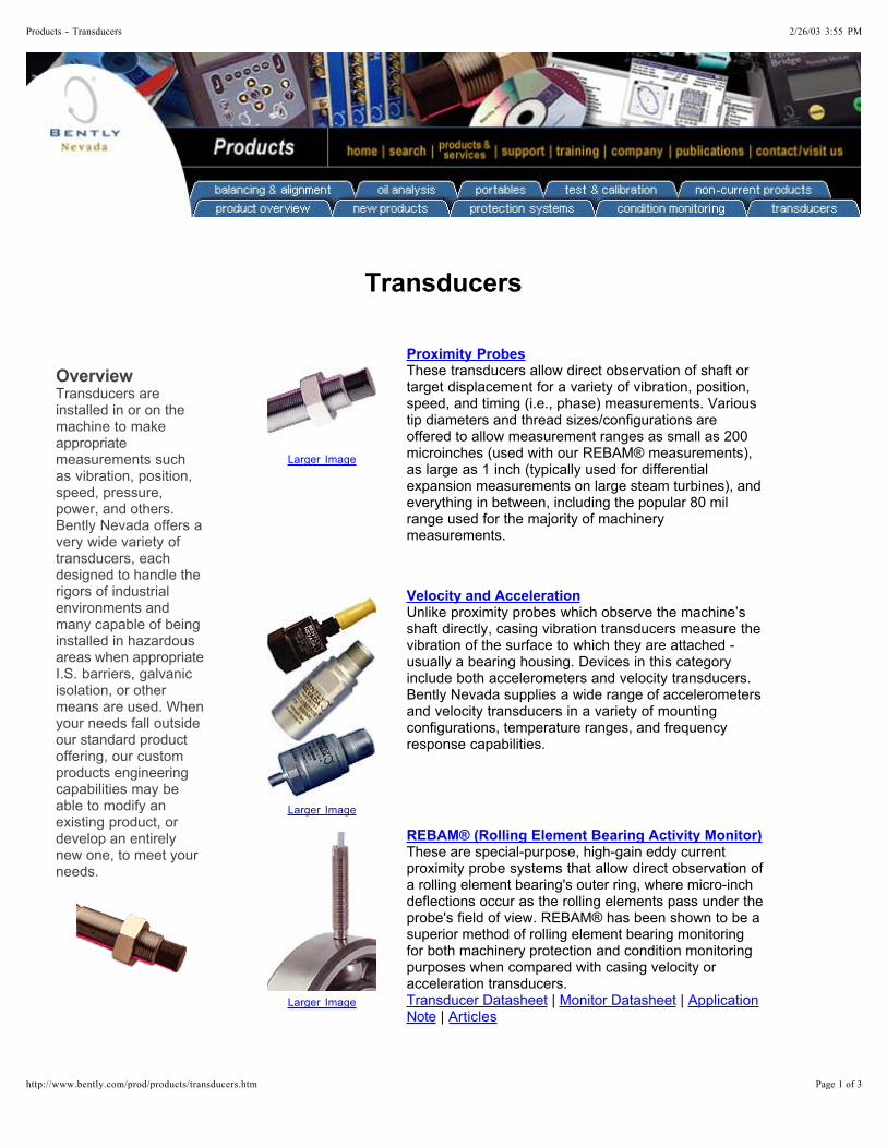
Transducers are installed in or on the machine to make appropriate measurements such as vibration, position, speed, pressure, power, and others. Bently Nevada offers a very wide variety of transducers, each designed to handle the rigors of industrial environments and many capable of being installed in hazardous areas when appropriate I.S. barriers, galvanic isolation, or other means are used. When your needs fall outside our standard product offering, our custom products engineering capabilities may be able to modify an existing product, or develop an entirely new one, to meet your needs.
Overview
Larger Image
These transducers allow direct observation of shaft or target displacement for a variety of vibration, position, speed, and timing (i.e., phase) measurements. Various tip diameters and thread sizes/configurations are offered to allow measurement ranges as small as 200 microinches (used with our REBAM® measurements), as large as 1 inch (typically used for differential expansion measurements on large steam turbines), and everything in between, including the popular 80 mil range used for the majority of machinery measurements.
Proximity Probes
Larger Image
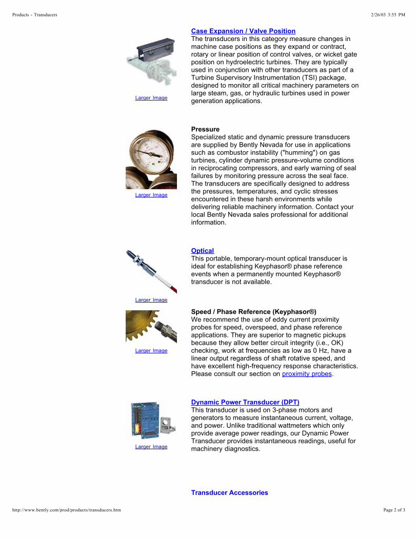
Unlike proximity probes which observe the machine’s shaft directly, casing vibration transducers measure the vibration of the surface to which they are attached - usually a bearing housing. Devices in this category include both accelerometers and velocity transducers. Bently Nevada supplies a wide range of accelerometers and velocity transducers in a variety of mounting configurations, temperature ranges, and frequency response capabilities.
Velocity and Acceleration
Larger Image
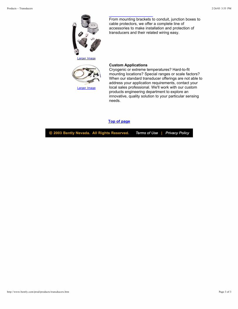
These are special-purpose, high-gain eddy current proximity probe systems that allow direct observation of a rolling element bearing's outer ring, where micro-inch deflections occur as the rolling elements pass under the probe's field of view. REBAM® has been shown to be a superior method of rolling element bearing monitoring for both machinery protection and condition monitoring purposes when compared with casing velocity or acceleration transducers.
| | |
REBAM® (Rolling Element Bearing Activity Monitor)
Transducer Datasheet Monitor Datasheet ApplicationNote Articles
2/26/03 3:55 PMProducts - Transducers
Page 1 of 3http://www.bently.com/prod/products/transducers.htm
Larger Image
The transducers in this category measure changes in machine case positions as they expand or contract, rotary or linear position of control valves, or wicket gate position on hydroelectric turbines. They are typically used in conjunction with other transducers as part of a Turbine Supervisory Instrumentation (TSI) package, designed to monitor all critical machinery parameters on large steam, gas, or hydraulic turbines used in power generation applications.
Case Expansion / Valve Position
Larger Image
Specialized static and dynamic pressure transducers are supplied by Bently Nevada for use in applications such as combustor instability ("humming") on gas turbines, cylinder dynamic pressure-volume conditions in reciprocating compressors, and early warning of seal failures by monitoring pressure across the seal face. The transducers are specifically designed to address the pressures, temperatures, and cyclic stresses encountered in these harsh environments while delivering reliable machinery information. Contact your local Bently Nevada sales professional for additional information.
Pressure
Larger Image
This portable, temporary-mount optical transducer is ideal for establishing Keyphasor® phase reference events when a permanently mounted Keyphasor® transducer is not available.
Optical
Larger Image
We recommend the use of eddy current proximity probes for speed, overspeed, and phase reference applications. They are superior to magnetic pickups because they allow better circuit integrity (i.e., OK) checking, work at frequencies as low as 0 Hz, have a linear output regardless of shaft rotative speed, and have excellent high-frequency response characteristics. Please consult our section on .
Speed / Phase Reference (Keyphasor®)
proximity probes
Larger Image
This transducer is used on 3-phase motors and generators to measure instantaneous current, voltage, and power. Unlike traditional wattmeters which only provide average power readings, our Dynamic Power Transducer provides instantaneous readings, useful for machinery diagnostics.
Dynamic Power Transducer (DPT)
Transducer Accessories
2/26/03 3:55 PMProducts - Transducers
Page 2 of 3http://www.bently.com/prod/products/transducers.htm
Larger Image
From mounting brackets to conduit, junction boxes to cable protectors, we offer a complete line of accessories to make installation and protection of transducers and their related wiring easy.
Larger Image
Cryogenic or extreme temperatures? Hard-to-fit mounting locations? Special ranges or scale factors? When our standard transducer offerings are not able to address your application requirements, contact your local sales professional. We'll work with our custom products engineering department to explore an innovative, quality solution to your particular sensing needs.
Custom Applications
Top of page
2/26/03 3:55 PMProducts - Transducers
Page 3 of 3http://www.bently.com/prod/products/transducers.htm
Michael David Bryant 10/2/07 ME 392Q Mechatronics 1 University of Texas at Austin 5
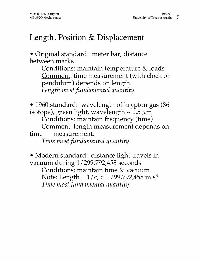
Length, Position & Displacement • Original standard: meter bar, distance between marks Conditions: maintain temperature & loads Comment: time measurement (with clock or pendulum) depends on length. Length most fundamental quantity. • 1960 standard: wavelength of krypton gas (86 isotope), green light, wavelength ~ 0.5 µm Conditions: maintain frequency (time) Comment: length measurement depends on time measurement. Time most fundamental quantity. • Modern standard: distance light travels in vacuum during 1/299,792,458 seconds Conditions: maintain time & vacuum Note: Length = 1/c, c = 299,792,458 m s-1 Time most fundamental quantity.
Michael David Bryant 10/11/07 ME 392Q Mechatronics 1 University of Texas at Austin 7
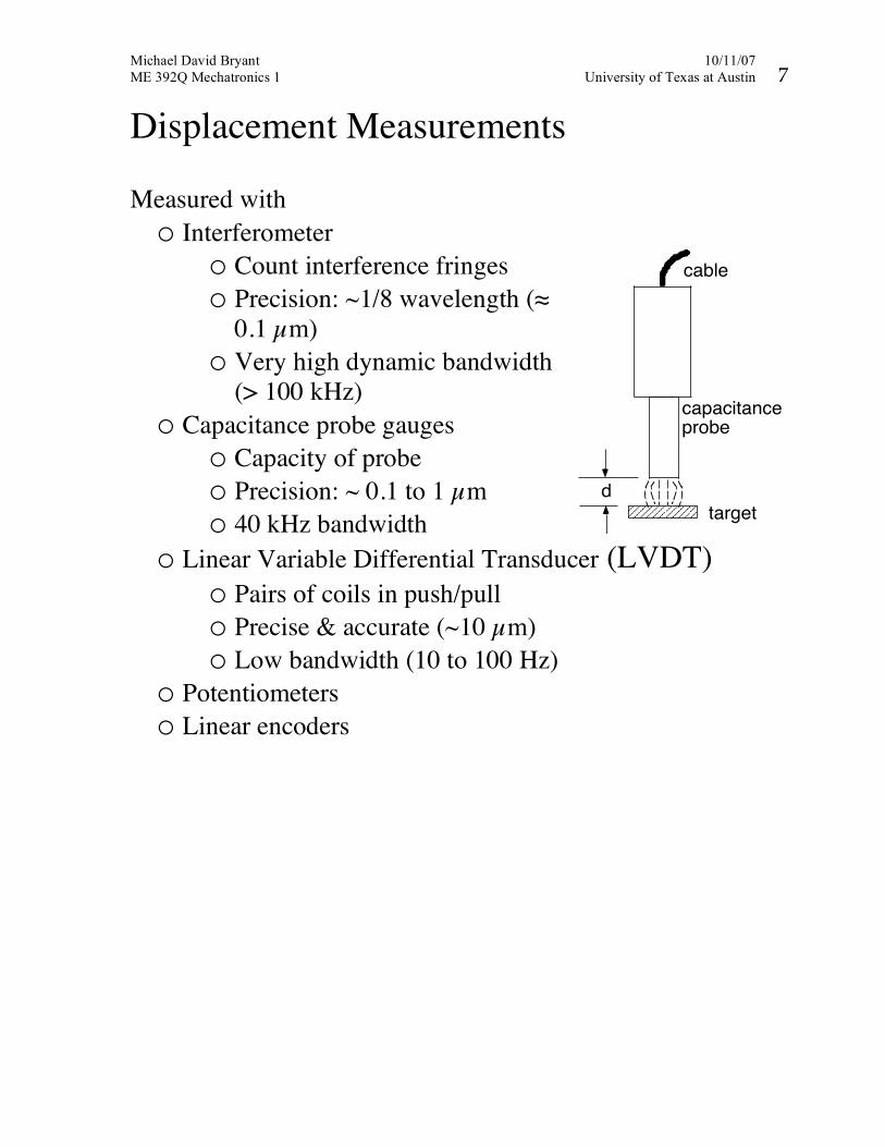
Displacement Measurements Measured with o Interferometer
o Count interference fringes o Precision: ~1/8 wavelength (≈
0.1 µm) o Very high dynamic bandwidth
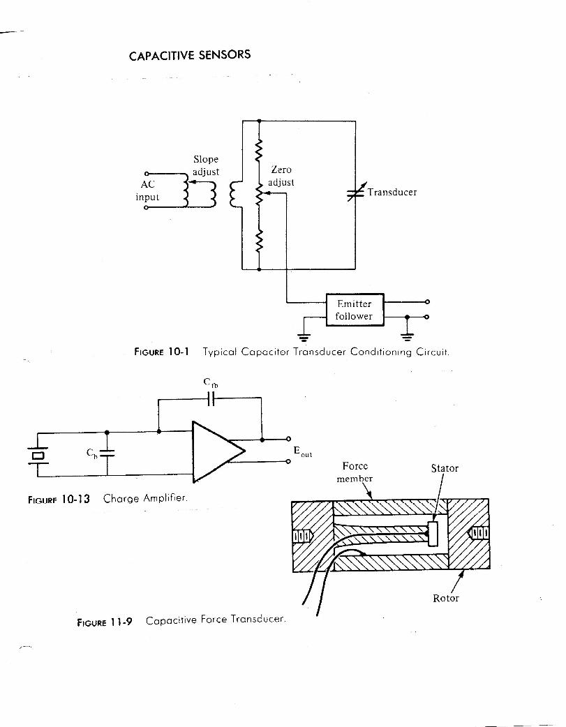
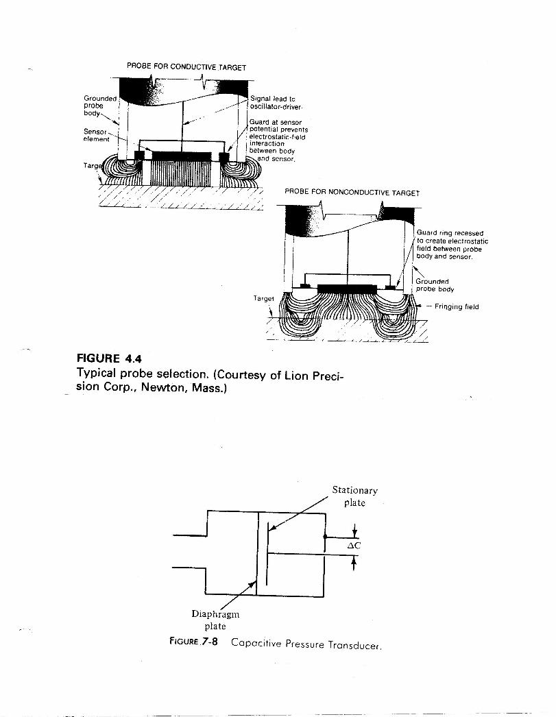
(> 100 kHz) o Capacitance probe gauges
o Capacity of probe o Precision: ~ 0.1 to 1 µm o 40 kHz bandwidth
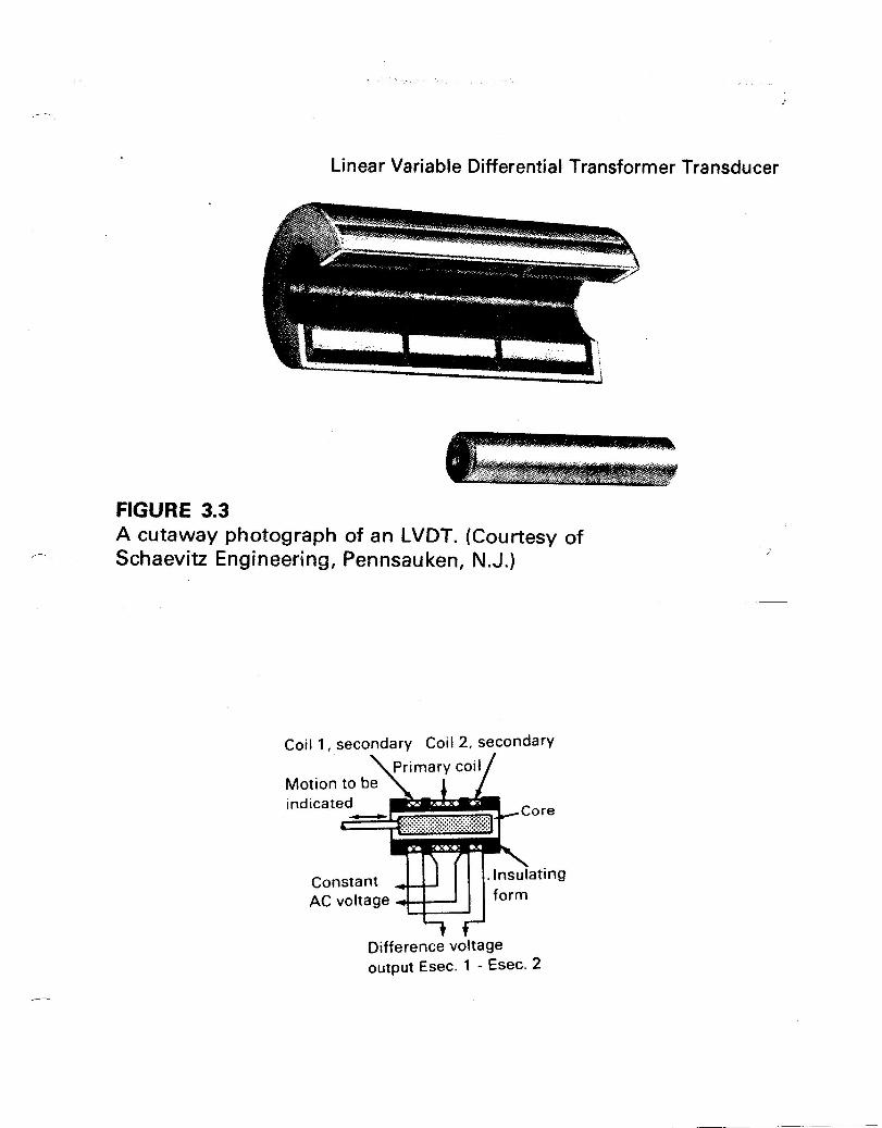
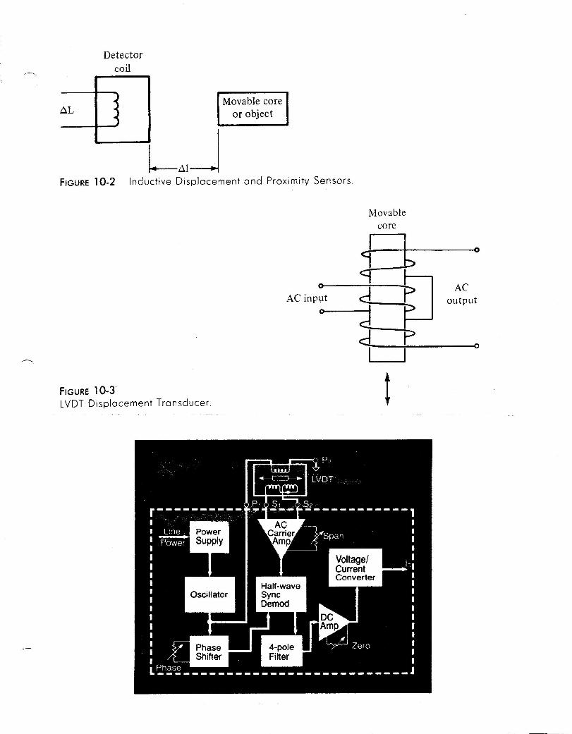
o Linear Variable Differential Transducer (LVDT) o Pairs of coils in push/pull o Precise & accurate (~10 µm) o Low bandwidth (10 to 100 Hz)
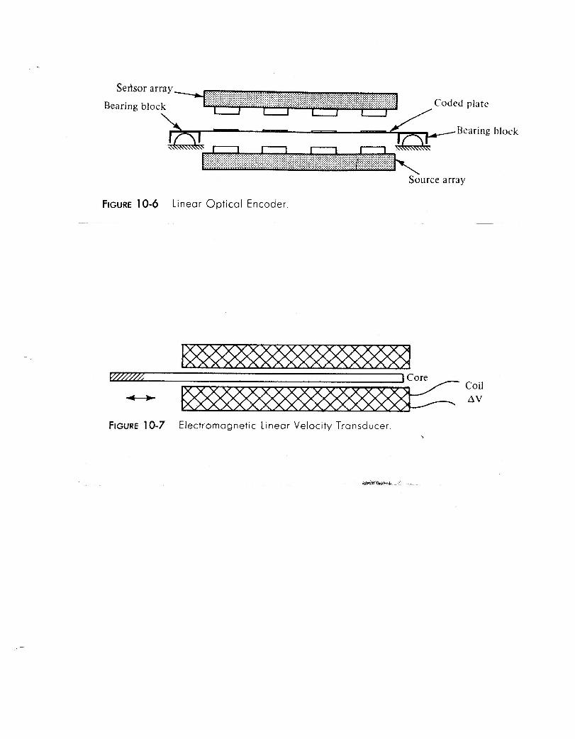
o Potentiometers o Linear encoders
target
capacitanceprobe
d
cable
Search this site02/12/03Database Last Updated:
> > > Categories Sensors, Transducers and Detectors Linear Position Sensing
LVDT Position SensorsFind quickly using GlobalSpec's Product FinderLVDT Position SensorsShow all products & suppliers for LVDT Position SensorsMore products in the areaSensors, Transducers and Detectors
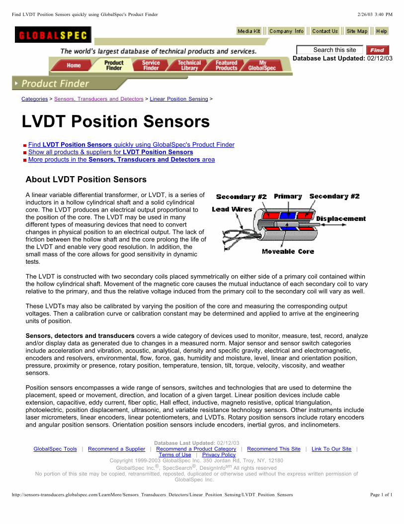
About LVDT Position Sensors
A linear variable differential transformer, or LVDT, is a series of inductors in a hollow cylindrical shaft and a solid cylindrical core. The LVDT produces an electrical output proportional to the position of the core. The LVDT may be used in many different types of measuring devices that need to convert changes in physical position to an electrical output. The lack of friction between the hollow shaft and the core prolong the life of the LVDT and enable very good resolution. In addition, the small mass of the core allows for good sensitivity in dynamic tests.
The LVDT is constructed with two secondary coils placed symmetrically on either side of a primary coil contained within the hollow cylindrical shaft. Movement of the magnetic core causes the mutual inductance of each secondary coil to vary relative to the primary, and thus the relative voltage induced from the primary coil to the secondary coil will vary as well.
These LVDTs may also be calibrated by varying the position of the core and measuring the corresponding output voltages. Then a calibration curve or calibration constant may be determined and applied to arrive at the engineering units of position.
covers a wide category of devices used to monitor, measure, test, record, analyze and/or display data as generated due to changes in a measured norm. Major sensor and sensor switch categories include acceleration and vibration, acoustic, analytical, density and specific gravity, electrical and electromagnetic, encoders and resolvers, environmental, flow, force, gas, humidity and moisture, level, linear and orientation position, pressure, proximity or presence, rotary position, temperature, tension, tilt, torque, velocity, viscosity, and weather sensors.
Position sensors encompasses a wide range of sensors, switches and technologies that are used to determine the placement, speed or movement, direction, and location of a given target. Linear position devices include cable extension, capacitive, eddy current, fiber optic, Hall effect, inductive, magneto resistive, optical triangulation, photoelectric, position displacement, ultrasonic, and variable resistance technology sensors. Other instruments include laser micrometers, linear encoders, linear potentiometers, and LVDTs. Rotary position sensors include rotary encoders and angular position sensors. Orientation position sensors include encoders, inertial gyros, and inclinometers.
Sensors, detectors and transducers
02/12/03 | | | | |
| Copyright 1999-2003 GlobalSpec Inc. 350 Jordan Rd, Troy, NY, 12180
GlobalSpec Inc. , SpecSearch , DesignInfo All rights reserved No portion of this site may be copied, retransmitted, reposted, duplicated or otherwise used without the express written permission of
GlobalSpec Inc.
Database Last Updated: GlobalSpec Tools Recommend a Supplier Recommend a Product Category Recommend This Site Link To Our Site
Terms of Use Privacy Policy
® ® sm
2/26/03 3:40 PMFind LVDT Position Sensors quickly using GlobalSpec's Product Finder
Page 1 of 1http://sensors-transducers.globalspec.com/LearnMore/Sensors_Transducers_Detectors/Linear_Position_Sensing/LVDT_Position_Sensors
NEW from MT/ Instruments!
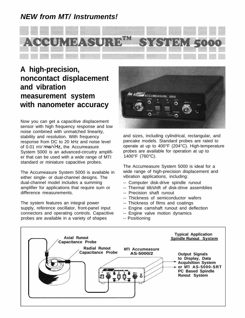
A high-precision,noncontact displacementand vibrationmeasurement systemwith nanometer accuracy
Now you can get a capacitive displacementsensor with high frequency response and lownoise combined with unmatched linearity,stability and resolution. With frequencyresponse from DC to 20 kHz and noise levelof 0.01 mV rms/dHz, the AccumeasureSystem 5000 is an advanced-circuitry amplifi-er that can be used with a wide range of MTIstandard or miniature capacitive probes.
The Accumeasure System 5000 is available ineither single- or dual-channel designs. Thedual-channel model includes a summingamplifier for applications that require sum ordifference measurements.
The system features an integral powersupply, reference oscillator, front-panel inputconnectors and operating controls. Capacitiveprobes are available in a variety of shapes
and sizes, including cylindrical, rectangular, andpancake models. Standard probes are rated tooperate at up to 400°F (204°C). High-temperatureprobes are available for operation at up to1400°F (760°C).
The Accumeasure System 5000 is ideal for awide range of high-precision displacement andvibration applications, including:-- Computer disk-drive spindle runout-- Thermal tilt/shift of disk-drive assemblies-- Precision shaft runout-- Thickness of semiconductor wafers-- Thickness of films and coatings-- Engine camshaft runout and deflection-- Engine valve motion dynamics-- Positioning
Axial RunoutTypical Application
Capacitance ProbeSpindle Runout System
Radial Runout MTI AccumeasureCapacitance Probe AS-5000/2 Output Signals
to Display, DataAcqulsltion Systemor MTI AS-5000-SRTPC Based SpindleRunout System
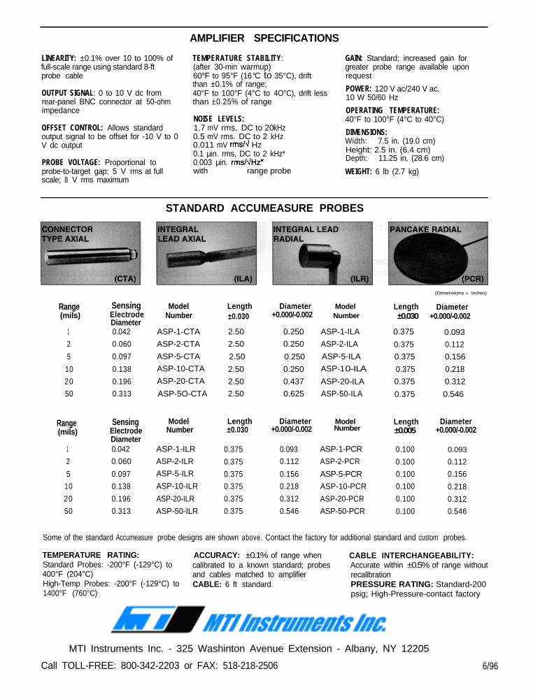
AMPLIFIER SPECIFICATIONS
LINEARITY: ±0.1% over 10 to 100% offull-scale range using standard 8-ftprobe cable
OUTPUT SIGNAL: 0 to 10 V dc fromrear-panel BNC connector at 50-ohmimpedance
OFFSET CONTROL: Allows standardoutput signal to be offset for -10 V to 0V dc output
PROBE VOLTAGE: Proportional toprobe-to-target gap; 5 V rms at fullscale; 8 V rms maximum
TEMPERATURE STABILITY:(after 30-min warmup)60°F to 95°F (16°C to 35°C), drift lessthan ±0.1% of range;40°F to 100°F (4°C to 4O°C), drift lessthan ±0.25% of range
NOISE LEVELS:1.7 mV rms, DC to 20 kHz0.5 mV rms, DC to 2 kHz0.011 mV rms/û Hz0.1 µin. rms, DC to 2 kHz*0.003 µin. rms/dHz’with 2000-µin .in . range probe
GAIN: Standard; increased gain forgreater probe range available uponrequest
POWER: 120 V ac/240 V ac,10 W 50/60 Hz
OPERATING TEMPERATURE:40°F to 100°F (4°C to 40°C)
DIMENSIONS:Width: 7.5 in. (19.0 cm)Height: 2.5 in. (6.4 cm)Depth: 11.25 in. (28.6 cm)
WEIGHT: 6 lb (2.7 kg)
STANDARD ACCUMEASURE PROBES
Range(mils)
1
2
5
10
20
50
Range(mils)
1
2
5
10
20
50
SensingElectrodeDiameter0.042
0.060
0.097
0.138
0.196
0.313
SensingElectrodeDiameter0.042
0.060
0.097
0.138
0.196
0.313
Model Length Diameter Model LengthNumber
±0.030
+0.000/-0.002 Number ±0.030
(Dimensions in Inches)
ASP-1-CTA 2.50 0.250 ASP-1-ILA 0.375 0.093ASP-2-CTA 2.50 0.250 ASP-2-ILA 0.375 0.112
ASP-5-CTA 2.50 0.250 ASP-5-ILA 0.375 0.156
ASP-10-CTA 2.50 0.250 ASP-1 0-ILA 0.375 0.218ASP-20-CTA 2.50 0.437 ASP-20-ILA 0.375 0.312
ASP-5O-CTA 2.50 0.625 ASP-50-ILA 0.375 0.546
ASP-1-ILR
ASP-2-ILR
ASP-5-ILR
ASP-10-ILR
ASP-20-ILR
ASP-50-ILR
0.375
0.375
0.375
0.375
0.375
0.375
0.093 ASP-1-PCR
0.112 ASP-2-PCR
0.156 ASP-5-PCR
0.218 ASP-10-PCR
0.312 ASP-20-PCR
0.546 ASP-50-PCR
0.100
0.100
0.100
0.100
0.100
0.100
0.093
0.112
0.156
0.218
0.312
0.546
Some of the standard Accumeasure probe designs are shown above. Contact the factory for additional standard and custom probes.
TEMPERATURE RATING: ACCURACY: ±0.1% of range when CABLE INTERCHANGEABILITY:Standard Probes: -200°F (-129°C) to calibrated to a known standard; probes Accurate within ±0.5% of range without400°F (204°C) and cables matched to amplifier recalibrationHigh-Temp Probes: -200°F (-129°C) to CABLE: 6 ft standard. PRESSURE RATING: Standard-2001400°F (760°C) psig; High-Pressure-contact factory
MTI Instruments Inc. - 325 Washinton Avenue Extension - Albany, NY 12205
Call TOLL-FREE: 800-342-2203 or FAX: 518-218-2506 6/96
Model Length Diameter Model LengthNumber
±0.030
Number ±0.005 +0.000/-0.002 +0.000/-0.002
Diameter
Diameter
+0.000/-0.002
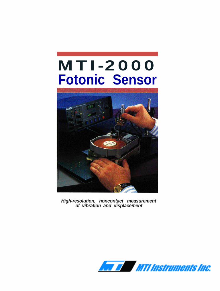
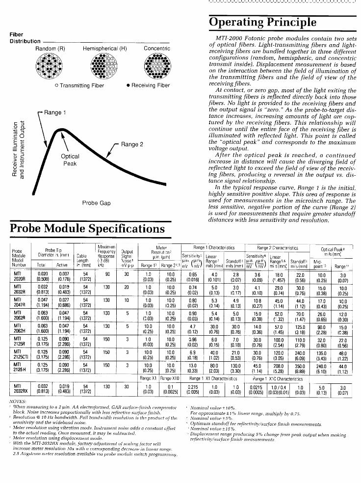
MTI-2000Fotonic Sensor
High-resolution, noncontact measurementof vibration and displacement
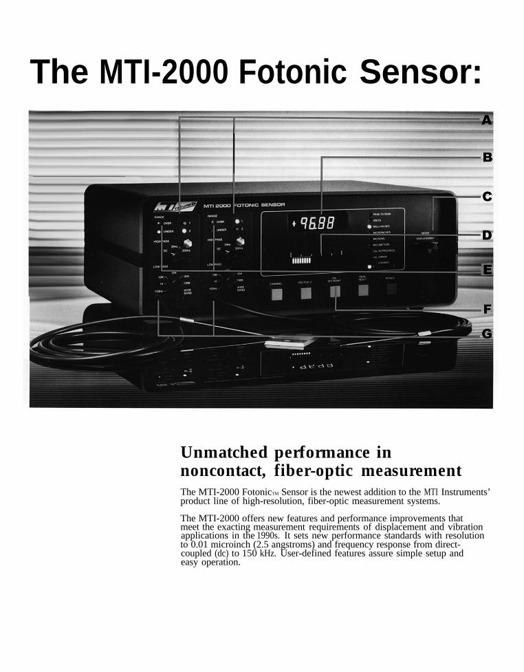
The MTI-2000 Fotonic Sensor:
Unmatched performance innoncontact, fiber-optic measurementThe MTI-2000 FotonicTM Sensor is the newest addition to the MTI Instruments’product line of high-resolution, fiber-optic measurement systems.
The MTI-2000 offers new features and performance improvements thatmeet the exactingapplications in the
measurement requirements of displacement and vibration 1990s. It sets new performance standards with resolution
to 0.01 microinch (2.5 angstroms) and frequency response from direct-coupled (dc) to 150 kHz. User-defined features assure simple setup andeasy operation.
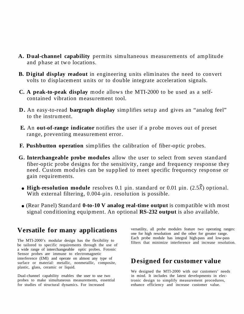
A. Dual-channel capability permits simultaneous measurements of amplitudeand phase at two locations.
B. Digital display readout in engineering units eliminates the need to convertvolts to displacement units or to double integrate acceleration signals.
C. A peak-to-peak display mode allows the MTI-2000 to be used as a self-contained vibration measurement tool.
D. An easy-to-read bargraph display simplifies setup and gives an “analog feel”to the instrument.
E. An out-of-range indicator notifies the user if a probe moves out of presetrange, preventing measurement error.
F. Pushbutton operation simplifies the calibration of fiber-optic probes.
G. Interchangeable probe modules allow the user to select from seven standardfiber-optic probe designs for the sensitivity, range and frequency response theyneed. Custom modules can be supplied to meet specific frequency response orgain requirements.
. High-resolution module resolves 0.1 µin. standard or 0.01 µin. (2.5A° ) optional.With external filtering, 0.004-µin. resolution is possible.
. (Rear Panel) Standard 0-to-10 V analog real-time output is compatible with mostsignal conditioning equipment. An optional RS-232 output is also available.
Versatile for many applicationsThe MTI-2000’s modular design has the flexibility tobe tailored to specific requirements through the use ofa wide range of interchangeable optic probes. FotonicSensor probes are immune to electromagneticinterference (EMI) and operate on almost any type ofsurface or material: metallic, nonmetallic, composite,plastic, glass, ceramic or liquid.
Dual-channel capability enables the user to use twoprobes to make simultaneous measurements, essentialfor studies of structural dynamics. For increased
versatility, all probe modules feature two operating ranges:one for high resolution and the other for greater range.Each probe module has integral high-pass and low-passfilters that minimize interference and increase resolution.
Designed for customer valueWe designed the MTI-2000 with our customers’ needsin mind. It includes the latest developments in elec-tronic design to simplify measurement procedures,enhance efficiency and increase customer value.
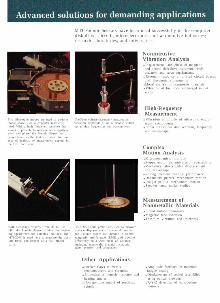
Two fiber-optic probes are used to perform The Fotonic Sensor accurately measures themodal analysis on a computer read/write vibration amplitude of on ultrasonic welderhead. With a high frequency response that tip at high frequencies and accelerations.makes it possible to measure both displace-ment and phase, the Fotonic Sensor hasbeen chosen as the best instrument for thistype of analysis by measurement experts inthe U.S. and Japan.
MTI Fotonic Sensors have been used successfully in the computerdisk-drive, aircraft, microelectronics and automotive industries;research laboratories; and universities.
NonintrusiveVibration Analysis.Displacement and phase of magnetic
and optical disk-drive read/write heads,actuators and servo mechanisms..Resonant response of printed circuit boardsand electronic components.Model analysis of composite materials.Vibration of fuel rods submerged in hotwater
High-FrequencyMeasurement.Vibration amplitude of ultrasonic equip-ment components.Sonar transducer displacement, frequencyand waveshape
ComplexMotion Analysis.Micromechanism motions.Stepper-motor dynamics and repeatability.Mechanical shock pulse displacement
and waveshape.Rolling element bearing performance.Dot-matrix printer mechanism motion.Ink-jet printer mechanism motion.Speaker cone modal studies
Measurement ofNonmetallic Materials.Liquid surface d ynamics.Magnetic tape vibration.Thin-film vibration and thickness
With frequency response from dc to 150 Two fiber-optic probes are used to measurekHz, the Fotonic Sensor is ideal fur analyz- surface displacement of a ceramic resona-ing squarewave and complex motions. The tor. Fotonic probes are immune to electro-MTI-2000 is used here to measure the abso- magnetic interference (EMI) and operatelute travel and bounce of a fuel-injector effectively on a wide range of surfacesvalve. including nonmetalic materials, ceramic,
glass, plastics, and composites.
Other Applications.Surface flaws in metals, .Amplitude feedback in materials
semiconductors and ceramics fatigue testing.Biomcchanics: muscle response and .Displacement of sealed assemblieshearing studies using optical viewport.Nonrepetitive runout of precision .X-Y-Z detection of out-of-planespindle motions
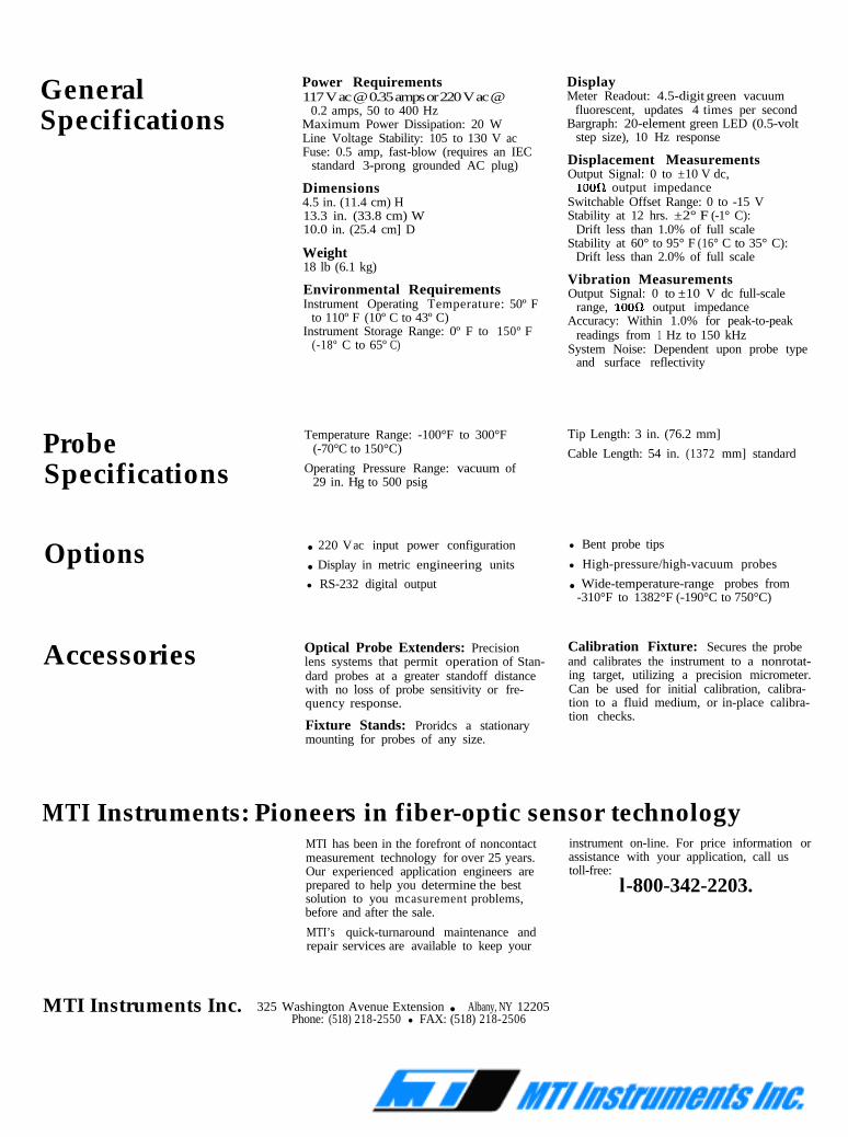
GeneralSpecifications
Power Requirements117 V ac @ 0.35 amps or 220 V ac @
0.2 amps, 50 to 400 HzMaximum Power Dissipation: 20 WLine Voltage Stability: 105 to 130 V acFuse: 0.5 amp, fast-blow (requires an IEC
standard 3-prong grounded AC plug)
Dimensions4.5 in. (11.4 cm) H
ProbeSpecifications
Options
Accessories
13.3 in. (33.8 cm) W10.0 in. (25.4 cm] D
Weight18 lb (6.1 kg)
Environmental RequirementsInstrument Operating Temperature: 50º F
to 110º F (10º C to 43º C)Instrument Storage Range: 0º F to 150º F
(-18º C to 65º C)
Temperature Range: -100°F to 300°F(-70°C to 150°C)
Operating Pressure Range: vacuum of29 in. Hg to 500 psig
. 220 V ac input power configuration. Display in metric engineering units
l RS-232 digital output
Optical Probe Extenders: Precisionlens systems that permit operation of Stan-dard probes at a greater standoff distancewith no loss of probe sensitivity or fre-quency response.
Fixture Stands: Proridcs a stationarymounting for probes of any size.
DisplayMeter Readout: 4.5-digit green vacuum
fluorescent, updates 4 times per secondBargraph: 20-element green LED (0.5-volt
step size), 10 Hz response
Displacement MeasurementsOutput Signal: 0 to ±10 V dc,
1000 output impedanceSwitchable Offset Range: 0 to -15 VStability at 12 hrs. ±2° F (-1° C):
Drift less than 1.0% of full scaleStability at 60° to 95° F (16° C to 35° C):
Drift less than 2.0% of full scale
Vibration MeasurementsOutput Signal: 0 to ±10 V dc full-scale
range, lOOa output impedanceAccuracy: Within 1.0% for peak-to-peak
readings from 1 Hz to 150 kHzSystem Noise: Dependent upon probe type
and surface reflectivity
Tip Length: 3 in. (76.2 mm]
Cable Length: 54 in. (1372 mm] standard
l Bent probe tips
l High-pressure/high-vacuum probes. Wide-temperature-range probes from-310°F to 1382°F (-190°C to 750°C)
Calibration Fixture: Secures the probeand calibrates the instrument to a nonrotat-ing target, utilizing a precision micrometer.Can be used for initial calibration, calibra-tion to a fluid medium, or in-place calibra-tion checks.
MTI Instruments: Pioneers in fiber-optic sensor technologyMTI has been in the forefront of noncontact instrument on-line. For price information ormeasurement technology for over 25 years. assistance with your application, call usOur experienced application engineers are toll-free:prepared to help you determine the bestsolution to you mcasurement problems,
l-800-342-2203.before and after the sale.
MTI’s quick-turnaround maintenance andrepair services are available to keep your
MTI Instruments Inc. 325 Washington Avenue Extension . Albany, NY 12205Phone: (518) 218-2550 l FAX: (518) 218-2506
®
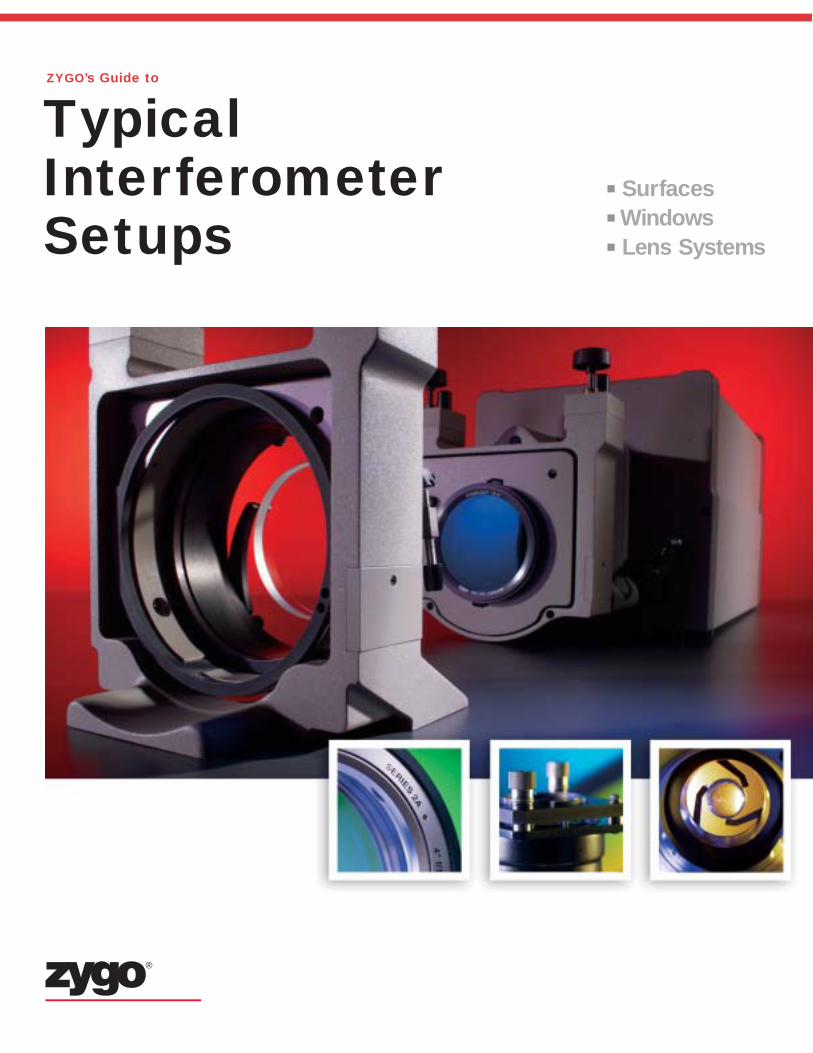
Typical Interferometer Setups
SurfacesWindowsLens Systems
ZYGO’s Guide to
Better Technology. Better Metrology.™
10 A Primer on Displacement Measuring Interferometers
Fixed Mirror
Monochromatic
Light Source
Beamsplitter
To Observer or Detector
Movable Mirror
Displacement(s)
λ/4 λ/4
OPLref
OPLmeas
OPL = Optical Path Length
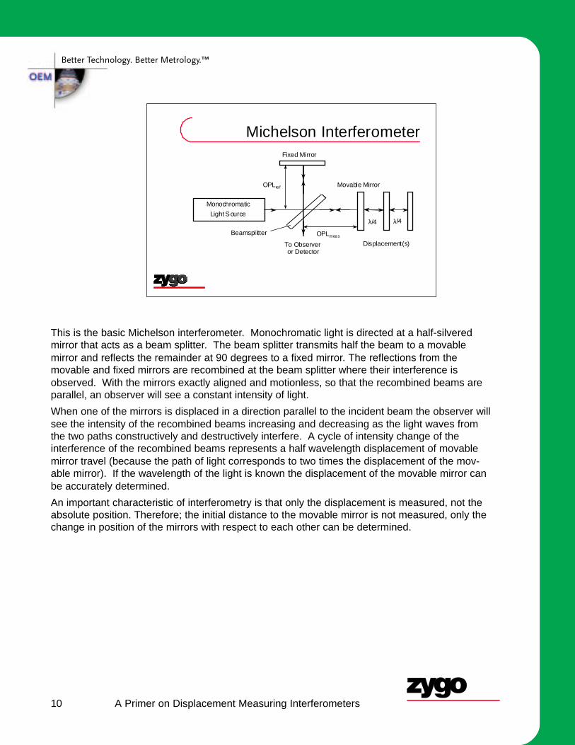
Michelson Interferometer
This is the basic Michelson interferometer. Monochromatic light is directed at a half-silveredmirror that acts as a beam splitter. The beam splitter transmits half the beam to a movablemirror and reflects the remainder at 90 degrees to a fixed mirror. The reflections from themovable and fixed mirrors are recombined at the beam splitter where their interference isobserved. With the mirrors exactly aligned and motionless, so that the recombined beams areparallel, an observer will see a constant intensity of light.
When one of the mirrors is displaced in a direction parallel to the incident beam the observer willsee the intensity of the recombined beams increasing and decreasing as the light waves fromthe two paths constructively and destructively interfere. A cycle of intensity change of theinterference of the recombined beams represents a half wavelength displacement of movablemirror travel (because the path of light corresponds to two times the displacement of the mov-able mirror). If the wavelength of the light is known the displacement of the movable mirror canbe accurately determined.
An important characteristic of interferometry is that only the displacement is measured, not theabsolute position. Therefore; the initial distance to the movable mirror is not measured, only thechange in position of the mirrors with respect to each other can be determined.
Better Technology. Better Metrology.™
11 A Primer on Displacement Measuring Interferometers
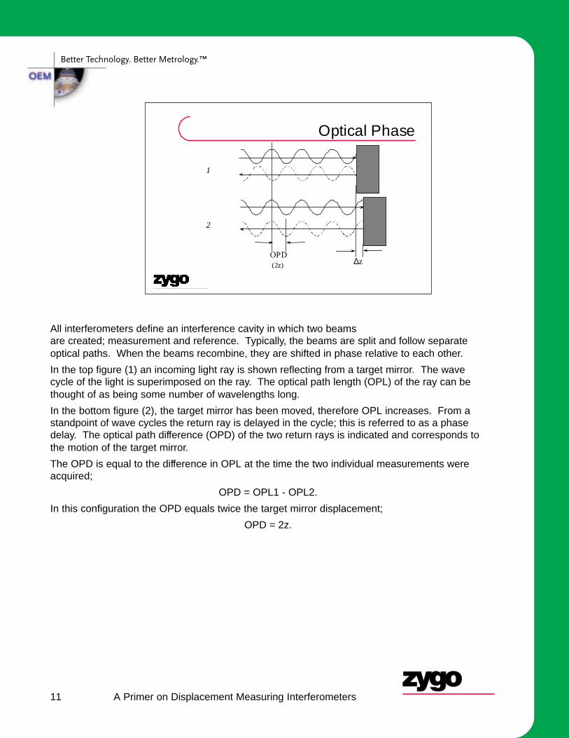
All interferometers define an interference cavity in which two beamsare created; measurement and reference. Typically, the beams are split and follow separateoptical paths. When the beams recombine, they are shifted in phase relative to each other.
In the top figure (1) an incoming light ray is shown reflecting from a target mirror. The wavecycle of the light is superimposed on the ray. The optical path length (OPL) of the ray can bethought of as being some number of wavelengths long.
In the bottom figure (2), the target mirror has been moved, therefore OPL increases. From astandpoint of wave cycles the return ray is delayed in the cycle; this is referred to as a phasedelay. The optical path difference (OPD) of the two return rays is indicated and corresponds tothe motion of the target mirror.
The OPD is equal to the difference in OPL at the time the two individual measurements wereacquired;
OPD = OPL1 - OPL2.
In this configuration the OPD equals twice the target mirror displacement;
OPD = 2z.
OPD (2z) ∆z
Optical Phase
1
2
Better Technology. Better Metrology.™
12 A Primer on Displacement Measuring Interferometers
Interferingwaves
Net E field Intensity
TotallyConstructive
TotallyDestructive
Identical waves complete ly overlapped
1
-1
1
-1 Identic al waves 180 degrees apar t
Interference
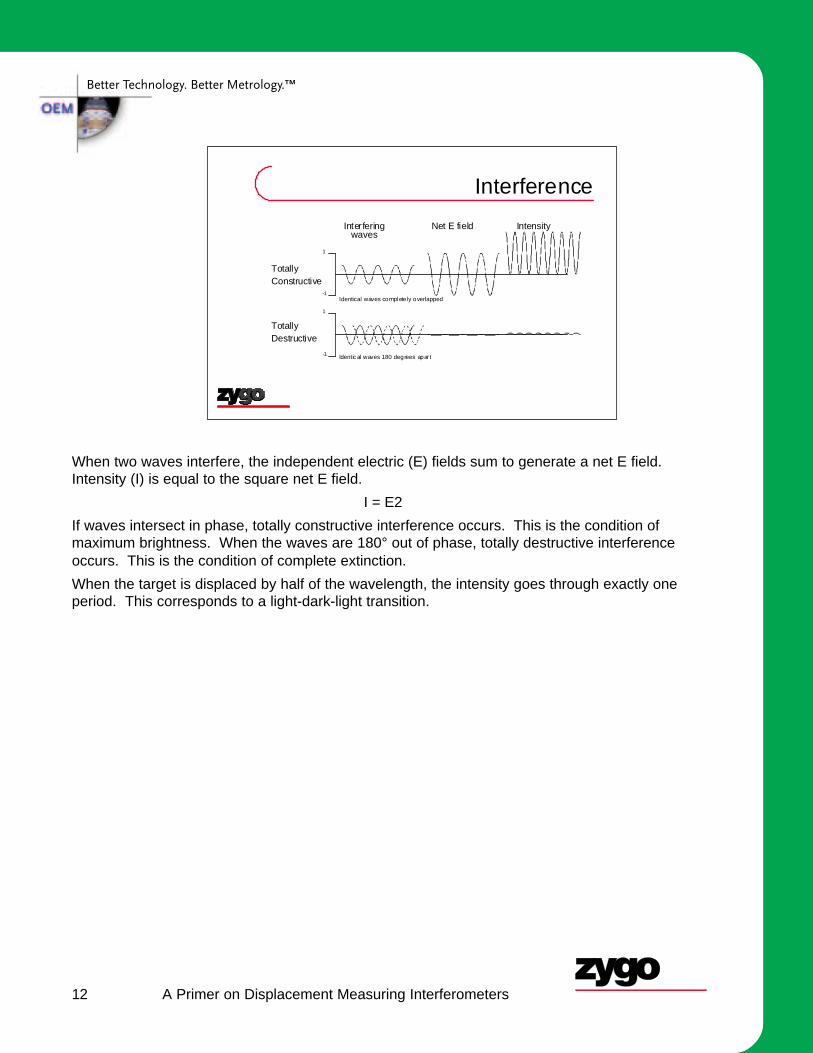
When two waves interfere, the independent electric (E) fields sum to generate a net E field.Intensity (I) is equal to the square net E field.
I = E2
If waves intersect in phase, totally constructive interference occurs. This is the condition ofmaximum brightness. When the waves are 180° out of phase, totally destructive interferenceoccurs. This is the condition of complete extinction.
When the target is displaced by half of the wavelength, the intensity goes through exactly oneperiod. This corresponds to a light-dark-light transition.
Michael David Bryant 10/19/06 ME 392Q Mechatronics 1 University of Texas at Austin 7
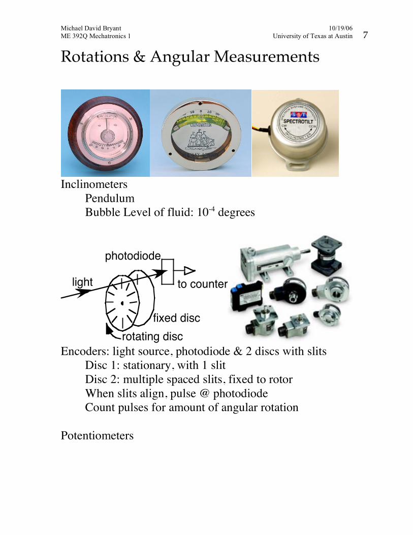
Rotations & Angular Measurements
Inclinometers Pendulum Bubble Level of fluid: 10-4 degrees
light
photodiode
fixed disc
rotating disc
to counter
Encoders: light source, photodiode & 2 discs with slits Disc 1: stationary, with 1 slit Disc 2: multiple spaced slits, fixed to rotor When slits align, pulse @ photodiode Count pulses for amount of angular rotation Potentiometers
Michael David Bryant 10/11/07 ME 392Q Mechatronics 1 University of Texas at Austin 9
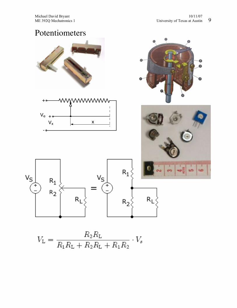
Potentiometers
+
Vx x
-
Ve +
Michael David Bryant 10/2/07 ME 392Q Mechatronics 1 University of Texas at Austin 9
Time Requires periodic event • Original standard: pendulum period Conditions: maintain pendulum length Comment: time derives from length Length most fundamental • 1960 standard: atomic clock Method: Excite Cesium atoms to higher energy, observe frequency (~ 9,192,631,770 Hz) of radiation Comment: length derives from time Current standard: average from 30 atomic clocks Precision = 1/9,192,631,770 = 1.1 x 10⁻¹⁰ s = 0.11 ns Time most fundamental • Future standard: optical clock Method: Excite (Mercury? Strontium? Ytterbium?) atoms with laser. Tune laser frequency to atom. Comments:
o frequencies 105 higher o Improved measurement
Michael David Bryant 10/11/07 ME 392Q Mechatronics 1 University of Texas at Austin 11
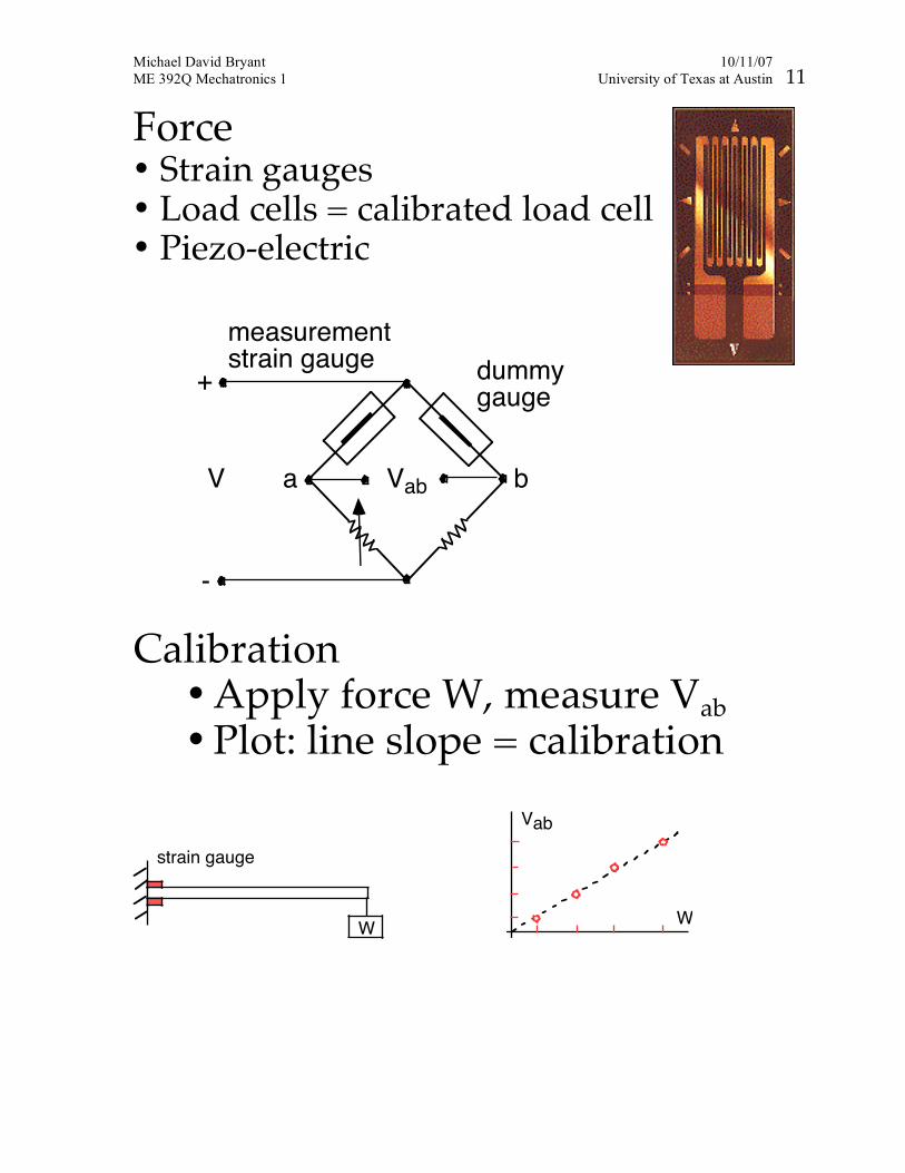
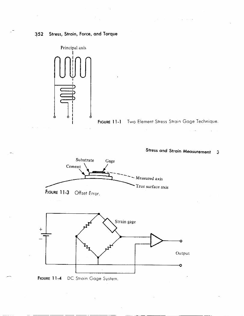
Force • Strain gauges • Load cells = calibrated load cell • Piezo-electric Calibration
• Apply force W, measure Vab • Plot: line slope = calibration
strain gauge
W W
Vab
VabV
dummygauge
a b
measurementstrain gauge
+
-
Michael David Bryant 10/9/07 ME 392Q Mechatronics 1 University of Texas at Austin 11
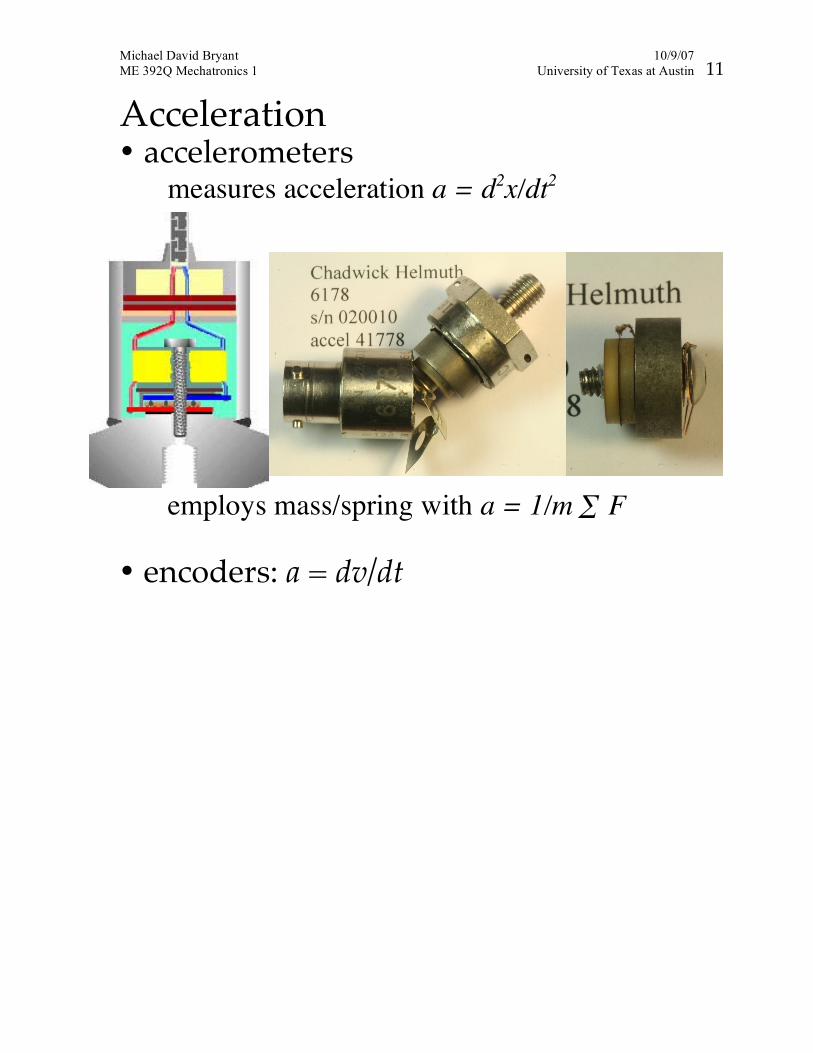
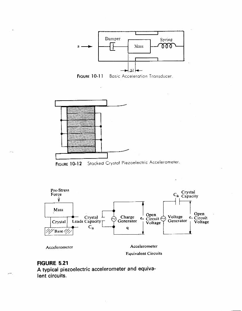
Acceleration • accelerometers measures acceleration a = d2x/dt2
employs mass/spring with a = 1/m ∑ F • encoders: a = dv/dt
Michael David Bryant 10/9/07 ME 392Q Mechatronics 1 University of Texas at Austin 12
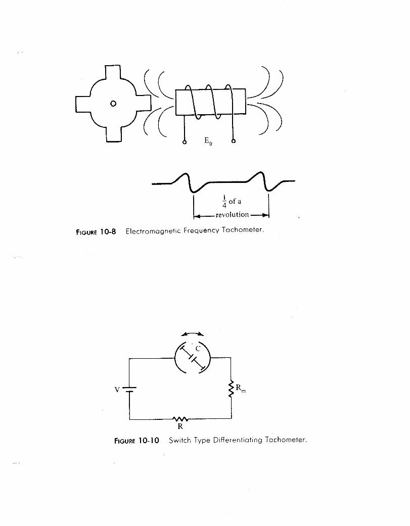
Velocity • tachometers • encoders • velometers: accelerometer with on-
board integrator
Michael David Bryant 10/11/07 ME 392Q Mechatronics 1 University of Texas at Austin 14
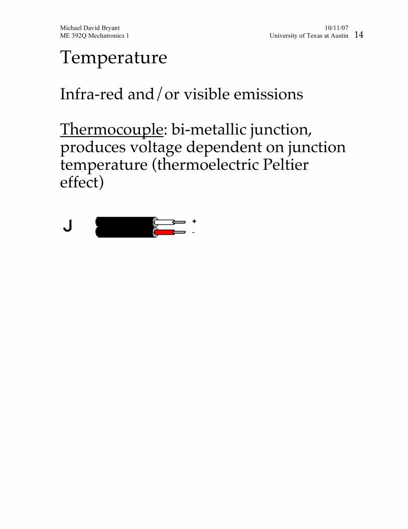
Temperature Infra-red and/or visible emissions Thermocouple: bi-metallic junction, produces voltage dependent on junction temperature (thermoelectric Peltier effect)