Embed Size (px)
Citation preview
Document #101-0036 1 03/20/06
ACW Enclosure withExternal Display
Installation Instructions
Document #101-0036 2 03/20/06
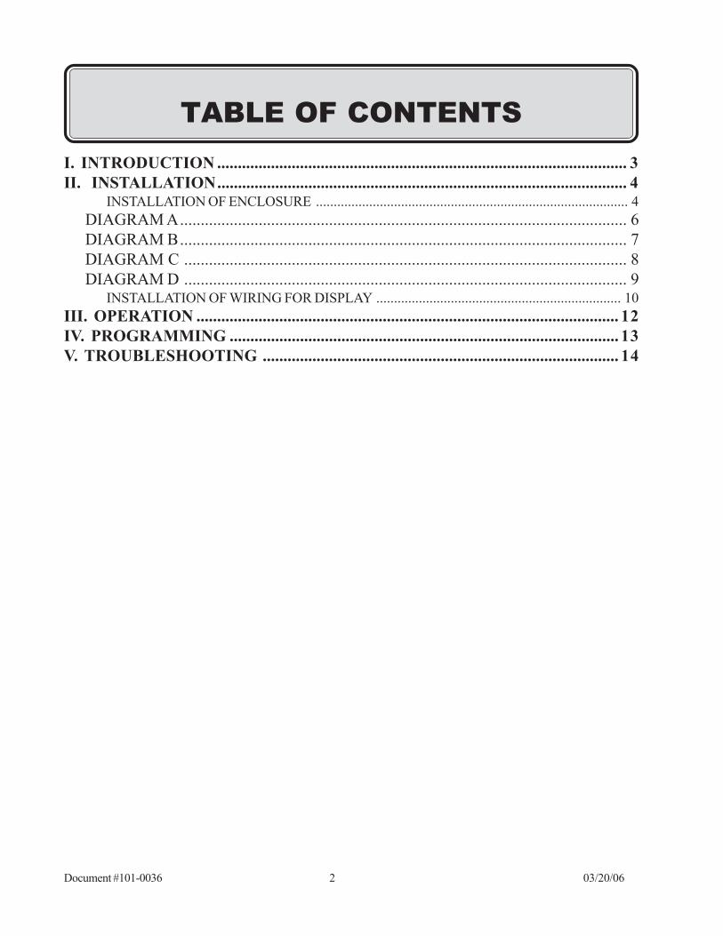
TABLE OF CONTENTSI. INTRODUCTION ................................................................................................... 3II. INSTALLATION................................................................................................... 4
INSTALLATION OF ENCLOSURE ........................................................................................ 4DIAGRAM A............................................................................................................ 6DIAGRAM B............................................................................................................ 7DIAGRAM C ........................................................................................................... 8DIAGRAM D ........................................................................................................... 9
INSTALLATION OF WIRING FOR DISPLAY ..................................................................... 10III. OPERATION ...................................................................................................... 12IV. PROGRAMMING .............................................................................................. 13V. TROUBLESHOOTING ...................................................................................... 14
Document #101-0036 3 03/20/06
I. INTRODUCTION
The Hamilton Manufacturing External Display is a bright, highly visible message center designed not only tohelp customers through their transaction, but also to attract new customers. The External Display provides a3" x 18" scrolling display visible from hundreds of feet away that is sure to attract attention.
While waiting for a customer to start a transaction, the External Display can display the same messages as theACW Controller, or custom messages that have been programmed by the operator. These custom messagescan be anything from additional information on using the car wash to special promotional messages. Suchmessages could include advertisements for weekly specials or discounted beverage prices in the attachedconvenience store. As soon as the customer takes some action, such as inserting money or choosing a washselection, the External Display will automatically duplicate the messages shown on the ACW Controller Dis-play. This helps the customer understand and use the wash more efficiently by seeing the instructions in such abold fashion.
To insure visibility and durability in a variety of situations, the External Display PCB Assembly is protected bya stainless steel enclosure incorporating a 1/4" thick lexan shield. This shield not only helps protect againstvandalism, but also helps filter out bright sunlight, making the display extremely visible in nearly all situations.
Document #101-0036 4 03/20/06
II. INSTALLATIONINSTALLATION OF ENCLOSURE
STEP 1. Switch off the power to the Auto Cashier at the main breaker panel.
STEP 2. Unlock and open the door to the Auto Cashier.
STEP 3. Break loose, but DO NOT REMOVE THE ANCHOR BOLT securing the
Autocashier to the base.
The Auto Cashier becomes top heavy when the door is open. IF BOLTS AREREMOVED ALL AT ONCE, THE UNIT MAY FALL OVER CAUSING INJURY.
STEP 4. Loosen the conduit connectors.
STEP 5. Remove the two anchor bolts on the RIGHT SIDE of the bottom of the Auto Cashier. LEAVE THE ANCHOR BOLTS ON THE LEFT SIDE IN PLACE.
STEP 6. Lift up the right side of the Autocashier approximately 1/2". Slide the bottom flange of theRIGHT SIDE PIECE under the Auto Cashier. Make sure the front flange of the RIGHTSIDE is in front of the flange that is already part of the Auto Cashier. Maneuver the SIDEPIECE and the Auto Cashier cabinet around until all the holes line up.
STEP 7. Reinstall the anchor bolts, but do not tighten completely.
STEP 8. Repeat steps 6 & 7 for the LEFT SIDE PIECE. REMOVE ONLY THE LEFT SIDEANCHOR BOLTS.
STEP 9. Set the LIGHT BRACKET on the top of the two SIDE PIECES. Make sure that the SIDEPIECES set outside of the small tabs located at the front, lower outside edges of theLIGHT BRACKET.
STEP 10. Install four 10-24 x 3/8" screws to secure the LIGHT BRACKET to the SIDE PIECES.Make sure the edges of the LIGHT BRACKET are flush with the outside surfaces of theSIDE PIECES before tightening the screws.
STEP 11. Run conduit up from the conduit hole in the back of the machine to the utility box intendedfor the fluorescent lamp wiring. Follow all applicable local codes. It is recommended to usea separate breaker for the fluorescent lamp so that it can be turned off during the day.
STEP 12. Remove the knockouts from the mounting holes in back of the Auto Cashier cabinet.
STEP 13. Remove the 1/4 x 20" nuts from the studs on the BACK PIECE.
STEP 14. Push the BACK PIECE studs through the holes on the SIDE PIECES and the back of thecabinet.
Document #101-0036 5 03/20/06
STEP 15. Reinstall the 1/4 x 20" nuts onto the studs, but do not tighten.
STEP 16. Make sure the SIDE PIECES are pushed toward the center of the cabinet as far aspossible and tighten the anchor bolts.
STEP 17. Tighten the nuts.
STEP 18. The TOP PIECE is designed to slide forward and slip into catches on the rear of theLIGHT BRACKET. Set the TOP PIECE onto the LIGHT BRACKET about two inchesrearward of the closed position. Hold the front of the TOP PIECE up about 1/2" to clearthe Display and push forward until it stops. Push down on the TOP PIECE to set it inplace.
STEP 19. Install two security screws from the underside of the LIGHT BRACKET and into the TOPPIECE.
Document #101-0036 6 03/20/06
QTY.DESCRIPTIONPART#ITEM#
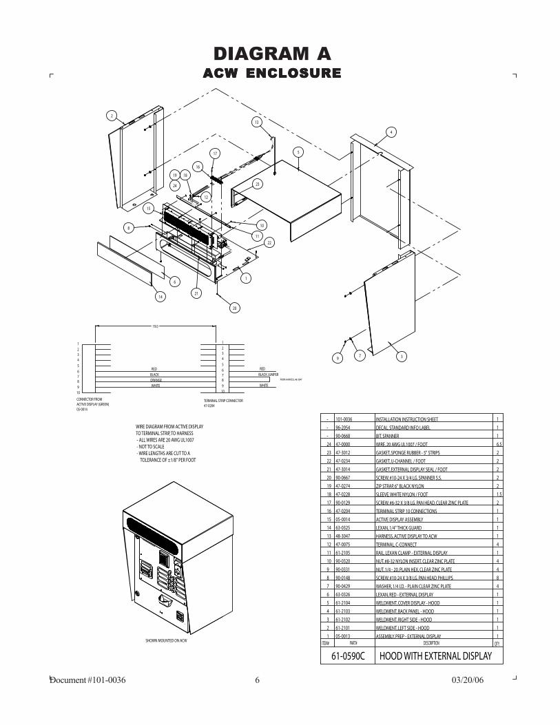
61-0590C HOOD WITH EXTERNAL DISPLAY
1BIT, SPANNER- 90-0668
6.5WIRE, 20 AWG UL1007 / FOOT47-000024
247-301223
2GASKET, U-CHANNEL / FOOT47-023422
2GASKET, EXTERNAL DISPLAY SEAL / FOOT47-301421
2SCREW, #10-24 X 3/4 LG. SPANNER S.S.90-066720
1INSTALLATION INSTRUCTION SHEET101-0036-
1DECAL, STANDARD INFO LABEL96-2054-
2ZIP STRAP, 6" BLACK NYLON47-027419
1.5SLEEVE, WHITE NYLON / FOOT47-022818
1ASSEMBLY, PREP - EXTERNAL DISPLAY1 05-0013
2 61-2101 WELDMENT, LEFT SIDE - HOOD 1
3 61-2102 WELDMENT, RIGHT SIDE - HOOD 1
4 61-2103 WELDMENT, BACK PANEL - HOOD 1
5 61-2104 WELDMENT, COVER DISPLAY - HOOD 1
6 63-0326 LEXAN, RED - EXTERNAL DISPLAY 1
7 90-0429 WASHER, 1/4 I.D. - PLAIN CLEAR ZINC PLATE 4
8 90-0148
9 90-0331 NUT, 1/4 - 20, PLAIN HEX, CLEAR ZINC PLATE 4
10 90-0320 NUT, #8-32 NYLON INSERT, CLEAR ZINC PLATE 4
11 61-2105 RAIL, LEXAN CLAMP - EXTERNAL DISPLAY 1
12 47-0075 TERMINAL, C-CONNECT 4
13 48-3047 HARNESS, ACTIVE DISPLAY TO ACW 1
14 63-0325 LEXAN, 1/4" THICK GUARD 1
15 05-0014 ACTIVE DISPLAY ASSEMBLY 1
16 47-0204 TERMINAL STRIP 10 CONNECTIONS 1
17 90-0129 SCREW, #6-32 X 3/8 LG. PAN HEAD, CLEAR ZINC PLATE 2
GASKET, SPONGE RUBBER - 5" STRIPS
8SCREW, #10-24 X 3/8 LG. PAN HEAD PHILLIPS
WIRE DIAGRAM FROM ACTIVE DISPLAYTO TERMINAL STRIP, TO HARNESS - ALL WIRES ARE 20 AWG UL1007 - NOT TO SCALE - WIRE LENGTHS ARE CUT TO A TOLERANCE OF ±1/8" PER FOOT
FROM HARNESS, 48-3047
WHITE
BLACK JUMPER
RED
1
234
5
678
910
1
234
5
678
910
RED
BLACKORANGEWHITE
TERMINAL STRIP CONNECTOR47-0204
CONNECTOR FROM ACTIVE DISPLAY (GREEN)05-0014
19.0
1
2
3
4
5
6
7
8
9
10
11
12
13
14
15
16
17
1819
20
21
22
2324
SHOWN MOUNTED ON ACW
DIAGRAM AACW ENCLOSUREACW ENCLOSUREACW ENCLOSUREACW ENCLOSUREACW ENCLOSURE
Document #101-0036 7 03/20/06
ACW
CO
NTR
OLL
ER (
49-1
212A
)O
RAU
TOTE
C CO
NTR
OLL
ER (
49-1
201A
)
EXTE
RNAL
DIS
PLAY
TR
ANSF
ORM
ER A
SSEM
BLY
( 60-
0331
A )
TO H
OPP
ER
EXTE
NSI
ON
PLU
GTO
SYS
TEM
HAR
NES
SH
OPP
ER P
LUG
2221
2019
1817
1615
1413
1211
109
87
65
43
21
WH
ITE/
GRE
EN
BRO
WN
BRO
WN
GRE
EN
WH
ITE
WH
ITE/
RED
RED
BLAC
K
EMPT
Y
COM
GN
D
L2 COM
DRO
P
HO
PPER
L1
WH
ITE/
GRE
EN
BRO
WN
EMPT
Y
COM
9 10 11 12
4 3 2 1
BRO
WN
GRE
EN
WH
ITE
COM
GN
D
L25 6 7 8
4 3 2 1
WH
ITE/
RED
RED
BLAC
K
DRO
P
HO
PPER
L11 2 3 4
4 3 2 1
TRANSFORMER
24V
BLAC
K
WH
ITE
YELL
OW
L1L224 V
AC
BLAC
K
BLAC
K
BLU
E
L1L224 V
AC
L1L224 V
AC3 2 1
3 2 122
PO
SITI
ON
CAR
D
EDG
E AD
D IN
PIN
16
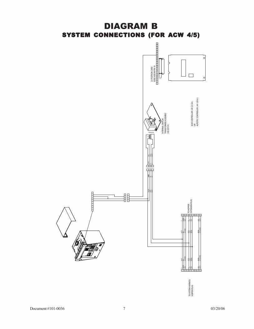
DIAGRAM BSYSYSYSYSYSTEM CONNECTIONS (FOR STEM CONNECTIONS (FOR STEM CONNECTIONS (FOR STEM CONNECTIONS (FOR STEM CONNECTIONS (FOR AAAAACW 4/5)CW 4/5)CW 4/5)CW 4/5)CW 4/5)
Document #101-0036 8 03/20/06
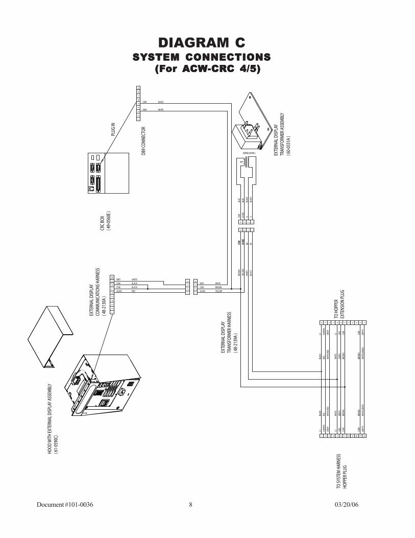
DIAGRAM CSYSYSYSYSYSTEM CONNECTIONSSTEM CONNECTIONSSTEM CONNECTIONSSTEM CONNECTIONSSTEM CONNECTIONS
(F(F(F(F(For or or or or AAAAACWCWCWCWCW-CR-CR-CR-CR-CRC 4/5)C 4/5)C 4/5)C 4/5)C 4/5)
12
34
56
78
24 VAC
910
COM
COM
XMIT
RED
BLACK
BLACK
WHITE
12
34
12
34
1234
24 VAC YELLOW
COM BROWN
XMIT WHITE
1234CO
M
24 VA
C
L2 L1
COM
24 VA
C
L2 L1
BLUE
BLUE
BLAC
K
BLAC
K
COM
24 VA
C
L2 L1
BROW
N
YELL
OW
WHI
TE
BLAC
K
24V
TRANSFORMER
1234
4321L1 HO
PPER
DROP
BLAC
K
RED
WHI
TE/R
ED
1234
8765L2 GN
D
COM
WHI
TE
GREE
N
BROW
N
1234
1211109
COM
EMPT
Y
BROW
N
WHI
TE/G
REEN
L1 HOPP
ER
DROP
COM
L2 GND
COM
EMPT
Y
BLAC
K
RED
WHI
TE/R
ED
WHI
TE
GREE
N
BROW
N
BROW
N
WHI
TE/G
REEN
EXTE
RNAL
DIS
PLAY
CO
MM
UNIC
ATIO
NS H
ARNE
SS( 4
8-21
30A
)
EXTE
RNAL
DIS
PLAY
TR
ANSF
ORM
ER H
ARNE
SS( 4
8-21
39A
)
TO SY
STEM
HAR
NESS
HOPP
ER P
LUG
TO H
OPPE
R EX
TENS
ION
PLUG
EXTE
RNAL
DIS
PLAY
TR
ANSF
ORM
ER A
SSEM
BLY
( 60-
0331
A )
98
76
54
32
1
XMIT WHITE
COM BLACK
DB9
CONN
ECTO
R
PLUG
IN
CRC
BOX
( 49-
0560
E )
HOOD
WIT
H EX
TERN
AL D
ISPL
AY A
SSEM
BLY
( 61-
0590
C)
Document #101-0036 9 03/20/06
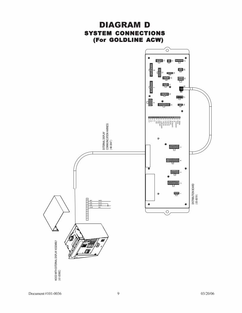
DIAGRAM DSYSYSYSYSYSTEM CONNECTIONSSTEM CONNECTIONSSTEM CONNECTIONSSTEM CONNECTIONSSTEM CONNECTIONS
(F(F(F(F(For GOLDLINE or GOLDLINE or GOLDLINE or GOLDLINE or GOLDLINE AAAAACW)CW)CW)CW)CW)
PRIN
TER
SOUN
DCA
RD R
EADE
REIC
CONT
ROLL
ERRE
FUND
BUTT
ON 4
BUTT
ON 3
BUTT
ON 2
BUTT
ON 1
HOPP
ER EM
PTY
COIN
DRO
PCO
IN 2
COIN
1$5$1+5V
+12V
22
2120
1918
1716
1514
1312
1110
9
87
6
54
32
1
DIST
RIBU
TION
BOA
RD( 0
5-00
19 )
EXTE
RNAL
DIS
PLAY
CO
MM
UNIC
ATIO
N HA
RNES
S( 4
8-30
47 )
12
34
56
78
24 VAC
910
COM
COM
XMIT
RED
BLACK
BLACK
WHITE
HOOD
WIT
H EX
TERN
AL D
ISPL
AY A
SSEM
BLY
( 61-
0590
C)
Document #101-0036 10 03/20/06
INSTALLATION OF WIRING FOR DISPLAY
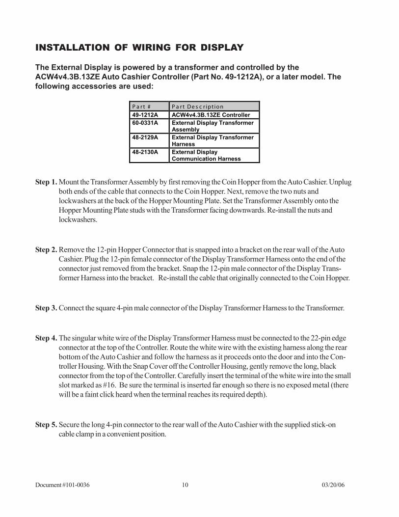
The External Display is powered by a transformer and controlled by theACW4v4.3B.13ZE Auto Cashier Controller (Part No. 49-1212A), or a later model. Thefollowing accessories are used:
Step 1. Mount the Transformer Assembly by first removing the Coin Hopper from the Auto Cashier. Unplugboth ends of the cable that connects to the Coin Hopper. Next, remove the two nuts andlockwashers at the back of the Hopper Mounting Plate. Set the Transformer Assembly onto theHopper Mounting Plate studs with the Transformer facing downwards. Re-install the nuts andlockwashers.
Step 2. Remove the 12-pin Hopper Connector that is snapped into a bracket on the rear wall of the AutoCashier. Plug the 12-pin female connector of the Display Transformer Harness onto the end of theconnector just removed from the bracket. Snap the 12-pin male connector of the Display Trans-former Harness into the bracket. Re-install the cable that originally connected to the Coin Hopper.
Step 3. Connect the square 4-pin male connector of the Display Transformer Harness to the Transformer.
Step 4. The singular white wire of the Display Transformer Harness must be connected to the 22-pin edgeconnector at the top of the Controller. Route the white wire with the existing harness along the rearbottom of the Auto Cashier and follow the harness as it proceeds onto the door and into the Con-troller Housing. With the Snap Cover off the Controller Housing, gently remove the long, blackconnector from the top of the Controller. Carefully insert the terminal of the white wire into the smallslot marked as #16. Be sure the terminal is inserted far enough so there is no exposed metal (therewill be a faint click heard when the terminal reaches its required depth).
Step 5. Secure the long 4-pin connector to the rear wall of the Auto Cashier with the supplied stick-oncable clamp in a convenient position.
P a r t # P a r t D e s c r ipt io n
49-1212A ACW4v4.3B.13ZE Controller
60-0331A External Display Transformer Assembly
48-2129A External Display Transformer Harness
48-2130A External Display Communication Harness
Document #101-0036 11 03/20/06
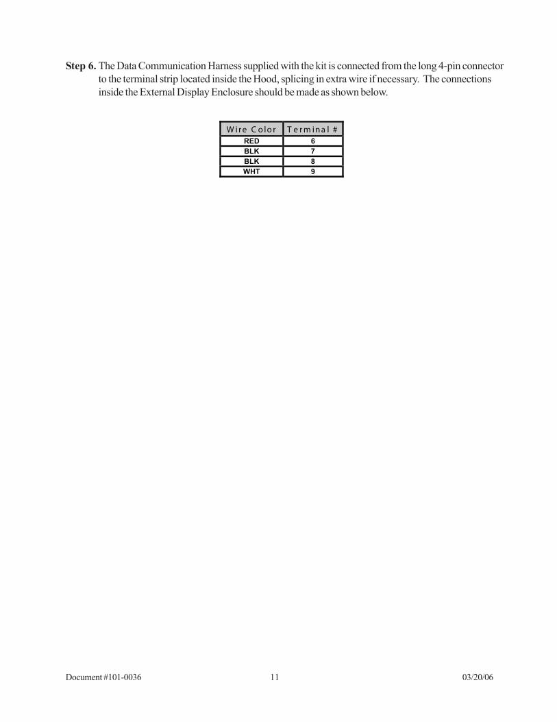
Step 6. The Data Communication Harness supplied with the kit is connected from the long 4-pin connectorto the terminal strip located inside the Hood, splicing in extra wire if necessary. The connectionsinside the External Display Enclosure should be made as shown below.
W ir e C o lo r T e r m in a l # RED 6
BLK 7
BLK 8
WHT 9
Document #101-0036 12 03/20/06
III. OPERATIONThe External Display receives serial data from the ACW Controller. The data received is then displayed in ascrolling fashion. The message being displayed depends on whether the ACW system is processing a transac-tion, and if Custom External Display Messages have been programmed.
First, in the case of processing a customer transaction, the External Display will exactly duplicate the messagesshown on the ACW Controller. For example, messages such as “Deposit $4.00 WASH & WAX”, “Credit$1.00”, and “Thank You! Please Drive Ahead” will be displayed. These messages help the customer to followthe transaction and understand what is to be done.
When there are no transactions being processed the messages displayed on the External Display will dependon whether any Custom External Display Messages have been programmed (instructions on how to programCustom External Display Messages are shown on page 8 of this manual). If all Custom External DisplayMessages have been programmed to “NOT USED “, the External Display will show the same messages as theACW Controller’s Welcome Messages.
If there are any Custom External Display Messages programmed and set to be displayed (any message not setto “NOT USED” will be displayed), these messages will be shown during this idle period. Up to 4 differentmessages of 40 characters each can be programmed. If more than one External Display Message is pro-grammed and displayed, the External Display will show each 40-character message for approximately 12seconds then display the next message. Twelve seconds allows each 40-character message to be scrolledacross the display approximately two times. This continues until all programmed messages have been dis-played and the cycle repeats.
Document #101-0036 13 03/20/06
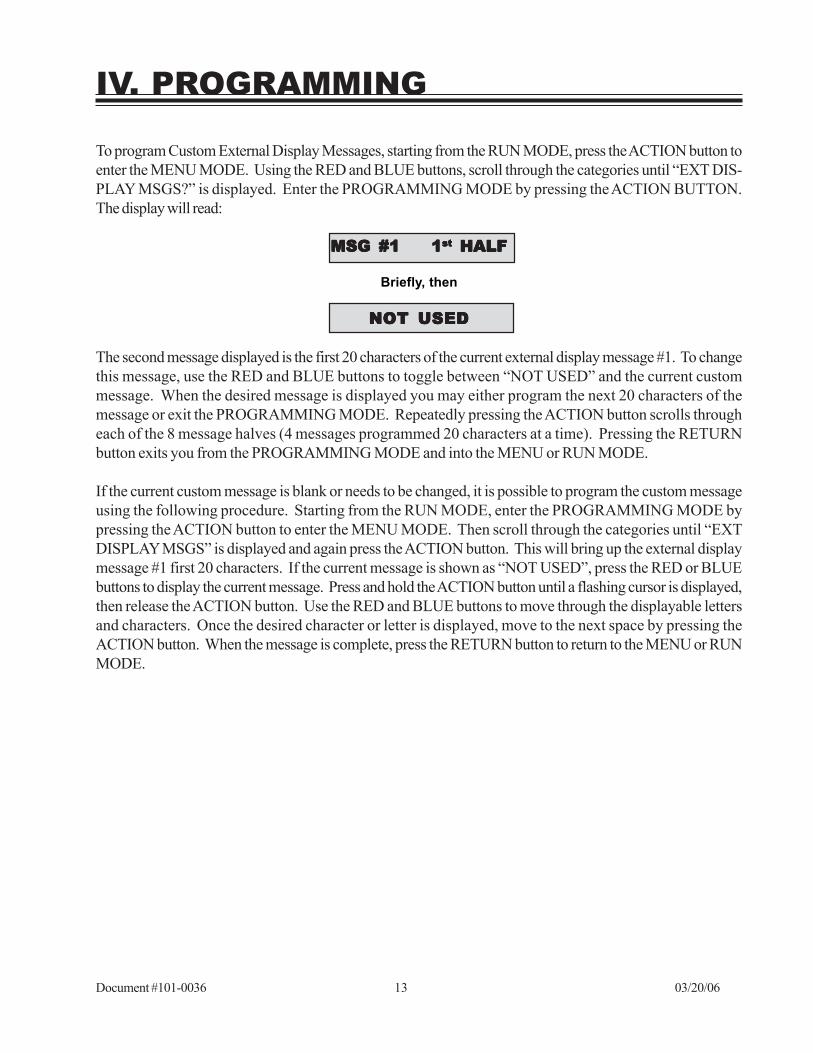
Briefly, then
NOT USEDNOT USEDNOT USEDNOT USEDNOT USED
The second message displayed is the first 20 characters of the current external display message #1. To changethis message, use the RED and BLUE buttons to toggle between “NOT USED” and the current custommessage. When the desired message is displayed you may either program the next 20 characters of themessage or exit the PROGRAMMING MODE. Repeatedly pressing the ACTION button scrolls througheach of the 8 message halves (4 messages programmed 20 characters at a time). Pressing the RETURNbutton exits you from the PROGRAMMING MODE and into the MENU or RUN MODE.
If the current custom message is blank or needs to be changed, it is possible to program the custom messageusing the following procedure. Starting from the RUN MODE, enter the PROGRAMMING MODE bypressing the ACTION button to enter the MENU MODE. Then scroll through the categories until “EXTDISPLAY MSGS” is displayed and again press the ACTION button. This will bring up the external displaymessage #1 first 20 characters. If the current message is shown as “NOT USED”, press the RED or BLUEbuttons to display the current message. Press and hold the ACTION button until a flashing cursor is displayed,then release the ACTION button. Use the RED and BLUE buttons to move through the displayable lettersand characters. Once the desired character or letter is displayed, move to the next space by pressing theACTION button. When the message is complete, press the RETURN button to return to the MENU or RUNMODE.
IV. PROGRAMMING
To program Custom External Display Messages, starting from the RUN MODE, press the ACTION button toenter the MENU MODE. Using the RED and BLUE buttons, scroll through the categories until “EXT DIS-PLAY MSGS?” is displayed. Enter the PROGRAMMING MODE by pressing the ACTION BUTTON.The display will read:
MSG #1 1MSG #1 1MSG #1 1MSG #1 1MSG #1 1ststststst HALF HALF HALF HALF HALF
Document #101-0036 14 03/20/06
V. TROUBLESHOOTING
P R O B L E M / T E S T
P O S I T I V E / Y E S
N E G A T I V E / N O
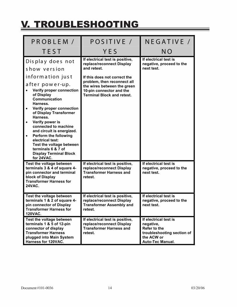
D is pla y do e s n o t s h o w v e r s io n in fo r m a t io n ju s t a f t e r po w e r -u p. Verify proper connection
of Display Communication Harness.
Verify proper connection of Display Transformer Harness.
Verify power is connected to machine and circuit is energized.
Perform the following electrical test: Test the voltage between terminals 6 & 7 of Display Terminal Block for 24VAC.
If electrical test is positive, replace/reconnect Display and retest. If this does not correct the problem, then reconnect all the wires between the green 10-pin connector and the Terminal Block and retest.
If electrical test is negative, proceed to the next test.
Test the voltage between terminals 3 & 4 of square 4-pin connector and terminal block of Display Transformer Harness for 24VAC.
If electrical test is positive, replace/reconnect Display Transformer Harness and retest.
If electrical test is negative, proceed to the next test.
Test the voltage between terminals 1 & 2 of square 4-pin connector of Display Transformer Harness for 120VAC.
If electrical test is positive, replace/reconnect Display Transformer Assembly and retest.
If electrical test is negative, proceed to the next test.
Test the voltage between terminals 1 & 5 of 12-pin connector of display Transformer Harness plugged into Main System Harness for 120VAC.
If electrical test is positive, replace/reconnect Display Transformer Harness and retest.
If electrical test is negative, Refer to the troubleshooting section of the ACW or Auto-Tec Manual.
Document #101-0036 15 03/20/06
P R O B L E M /
T E S T
P O S I T I V E /
Y E S
N E G A T I V E /
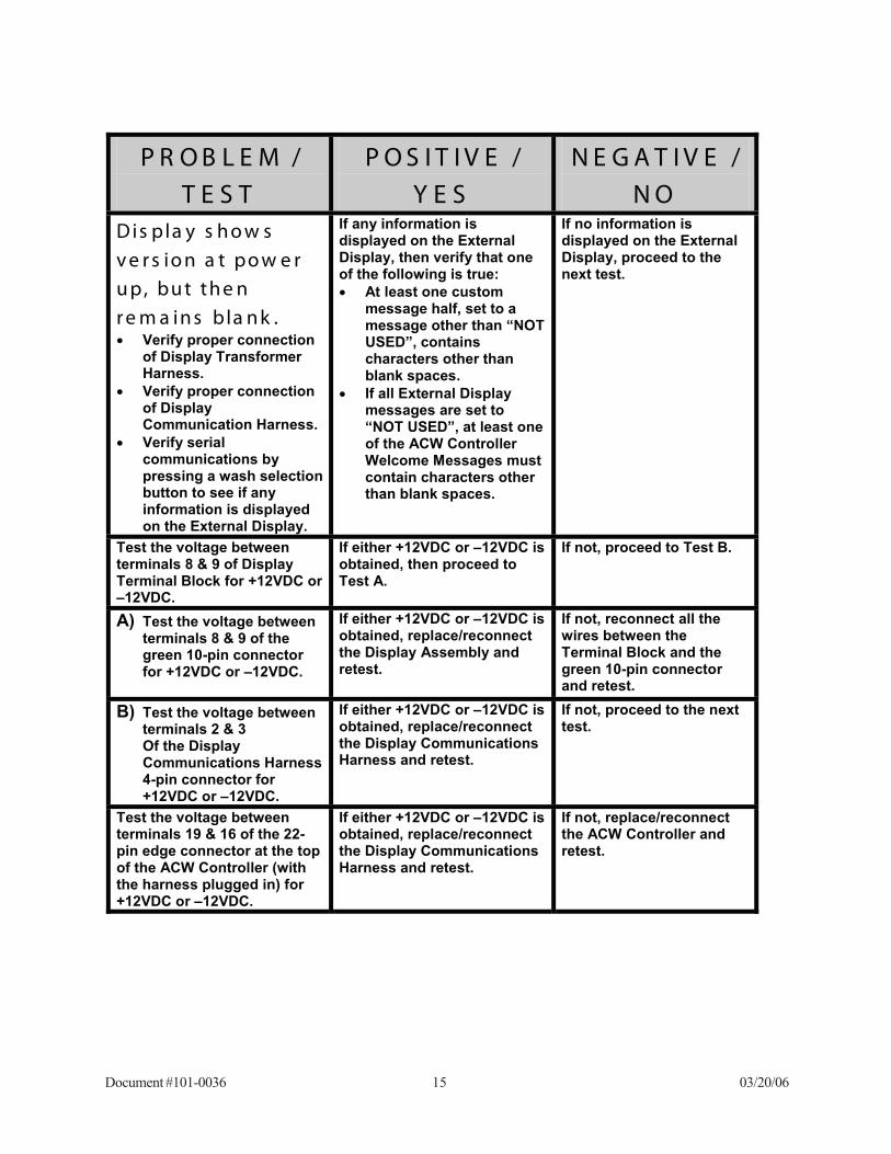
N O D is pla y s h o w s v e r s io n a t po w e r u p, bu t th e n r e m a in s bla n k . Verify proper connection
of Display Transformer Harness.
Verify proper connection of Display Communication Harness.
Verify serial communications by pressing a wash selection button to see if any information is displayed on the External Display.
If any information is displayed on the External Display, then verify that one of the following is true:
At least one custom message half, set to a message other than “NOT USED”, contains characters other than blank spaces.
If all External Display messages are set to “NOT USED”, at least one of the ACW Controller Welcome Messages must contain characters other than blank spaces.
If no information is displayed on the External Display, proceed to the next test.
Test the voltage between terminals 8 & 9 of Display Terminal Block for +12VDC or –12VDC.
If either +12VDC or –12VDC is obtained, then proceed to Test A.
If not, proceed to Test B.
A) Test the voltage between terminals 8 & 9 of the green 10-pin connector for +12VDC or –12VDC.
If either +12VDC or –12VDC is obtained, replace/reconnect the Display Assembly and retest.
If not, reconnect all the wires between the Terminal Block and the green 10-pin connector and retest.
B) Test the voltage between terminals 2 & 3 Of the Display Communications Harness 4-pin connector for +12VDC or –12VDC.
If either +12VDC or –12VDC is obtained, replace/reconnect the Display Communications Harness and retest.
If not, proceed to the next test.
Test the voltage between terminals 19 & 16 of the 22-pin edge connector at the top of the ACW Controller (with the harness plugged in) for +12VDC or –12VDC.
If either +12VDC or –12VDC is obtained, replace/reconnect the Display Communications Harness and retest.
If not, replace/reconnect the ACW Controller and retest.
Document #101-0036 16 03/20/06
P R O B L E M /
T E S T
P O S I T I V E /
Y E S
N E G A T I V E /
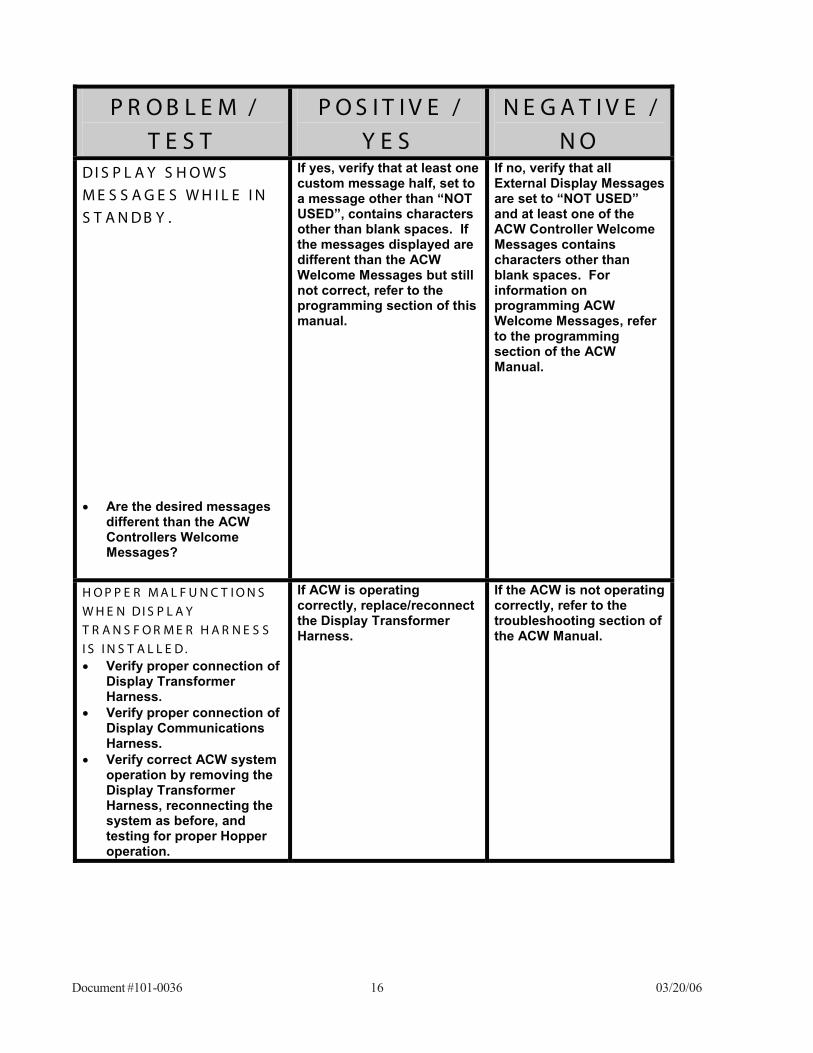
N O D I S P L A Y S H O W S M E S S A G E S W H I L E I N S T A N D B Y . Are the desired messages
different than the ACW Controllers Welcome Messages?
If yes, verify that at least one custom message half, set to a message other than “NOT USED”, contains characters other than blank spaces. If the messages displayed are different than the ACW Welcome Messages but still not correct, refer to the programming section of this manual.
If no, verify that all External Display Messages are set to “NOT USED” and at least one of the ACW Controller Welcome Messages contains characters other than blank spaces. For information on programming ACW Welcome Messages, refer to the programming section of the ACW Manual.
H O P P E R M A L F U N C T I O N S
W H E N D I S P L A Y T R A N S F O R M E R H A R N E S S
I S I N S T A L L E D . Verify proper connection of
Display Transformer Harness.
Verify proper connection of Display Communications Harness.
Verify correct ACW system operation by removing the Display Transformer Harness, reconnecting the system as before, and testing for proper Hopper operation.
If ACW is operating correctly, replace/reconnect the Display Transformer Harness.
If the ACW is not operating correctly, refer to the troubleshooting section of the ACW Manual.
Document #101-0036 17 03/20/06
LIMITED WARRANTY AGREEMENTLIMITED WARRANTY AGREEMENTLIMITED WARRANTY AGREEMENTLIMITED WARRANTY AGREEMENTLIMITED WARRANTY AGREEMENTOF HAMILOF HAMILOF HAMILOF HAMILOF HAMILTTTTTON MANUFON MANUFON MANUFON MANUFON MANUFAAAAACTURING CORPCTURING CORPCTURING CORPCTURING CORPCTURING CORP.....
Hamilton Manufacturing Corp., an Ohio Corporation, (“Seller”) warrants to Purchaser that all newequipment shall be free from defects in material and factory workmanship for a period of one (1) year from theoriginal shipping date. Hamilton Manufacturing Corp. further warrants if any part of said new equipment inSeller’s sole opinion, requires replacement or repair due to a defect in material or factory workmanship duringsaid period, Seller will repair or replace said new equipment. Purchaser’s remedies and the liabilities andobligations of Seller herein shall be limited to repair or replacement of the equipment as Seller may choose, andSeller’s obligation to remedy such defects shall not exceed the Purchaser’s original cost for the equipment.Purchaser EXPRESSLY AGREES this is the EXCLUSIVE REMEDY under this warranty. There are no otherexpress or implied warranties which extend beyond the face hereof. All warranty repair service must beperformed by either a Factory Trained Service Representative or HAMILTON MANUFACTURINGCORP., 1026 Hamilton Drive, Holland, Ohio 43528 PHONE (419) 867-4858 or (800) 837-5561, FAX(419) 867-4867.
The limited warranty for new equipment is conditioned upon the following:
1. The subject equipment has not, in the Seller’s sole opinion, been subjectedto: accident, abuse, misuse, vandalism, civil disobedience, riots, acts ofGod, natural disaster, acts of war or terrorism.
2. The Seller shall not be liable for any expense incurred by Purchaser inci-dental to the repair or replacement of equipment and Purchaser shallassume full responsibility for any freight or shipping charges.
3. The coverage of this warranty shall not extend to expendable parts.4. Purchaser shall have a warranty registration card on file with Seller prior to
any claim in order for warranty protection to apply.5. No warranty coverage is applicable to any equipment used for currency
other than that specified at the time of the purchase.6. Seller expressly disclaims any warranty that counterfeit currency will not
activate said equipment.7. Seller expressly disclaims any warranty for any losses due to bill manipula-
tion or theft or loss of cash under any circumstances.8. Use of the equipment for anything other than its intended and designed use
will void the Limited Warranty Agreement. Use of equipment for anythingother than its intended and designed use includes, but is not limited to,downloading software/applications not certified by Seller such as e-mail,spyware, screen savers, viruses, worms, third party software, web searchengines, cookies, spam, desktop applications, games, web surfing, etc.
Seller further warrants all repair or service work performed by a factory trained representative orHamilton Manufacturing Corp. for a period of ninety (90) days from the date the repair or service work wasperformed. Purchaser’s remedies and the liabilities and obligations of Seller herein shall be limited to repair orreplacement of equipment as Seller may choose, and Seller’s obligation to remedy such defects shall notexceed the Purchaser’s depreciated value of the equipment. Purchaser EXPRESSLY AGREES this is anEXCLUSIVE REMEDY under this warranty. There are no other express or implied warranties on repair orservice work performed by a factory trained representative or Hamilton Manufacturing Corp. which extendbeyond the face hereof.
Document #101-0036 18 03/20/06
The limited warranty for repair and service work is conditioned upon the following:
1. The subject equipment has not, in the Seller’s sole opinion, been subjectedto: accident, abuse, misuse, vandalism, civil disobedience, riots, acts ofGod, natural disaster, acts of war or terrorism.
2. The Seller shall not be liable for any expense incurred by Purchaser inciden-tal to the repair or replacement of equipment and Purchaser shall assume fullresponsibility for any freight or shipping charges.
3. The coverage of this warranty shall not extend to expendable parts.4. Purchaser shall have a warranty registration card on file with Seller prior to
any claim in order for warranty protection to apply.5. No warranty coverage is applicable to any equipment used for currency
other than that specified at the time of the purchase.6. Seller expressly disclaims any warranty that counterfeit currency will not
activate said equipment.7. Seller expressly disclaims any warranty for any losses due to bill manipula-
tion or theft or loss of cash under any circumstances.8. No person or entity other than a factory trained representative or Hamilton
Manufacturing Corp. has performed or attempted to perform the subjectrepair or service.
9. Using equipment which has been serviced or repaired for anything otherthan its intended or designed use such as downloading software applicationsnot certified by Seller will void the Limited Warranty Agreement. Thisincludes software/applications such as e-mail, spyware, screen savers,viruses, worms, third party software, web search engines, cookies, spam,desktop applications, games, web surfing, etc.
THIS AGREEMENT IS MADE WITH THE EXPRESS UNDERSTANDING THAT THERE ARENO IMPLIED WARRANTIES THAT THE EQUIPMENT SHALL BE MERCHANTABLE, OR THATTHE GOODS SHALL BE FIT FOR ANY PARTICULAR PURPOSE. PURCHASER HEREBY AC-KNOWLEDGES THAT IT IS NOT RELYING ON THE SELLER’S SKILL OR JUDGMENT TO SE-LECT OR FURNISH EQUIPMENT SUITABLE FOR ANY PARTICULAR PURPOSE AND THATTHERE ARE NO WARRANTIES WHICH EXTEND BEYOND THAT WHICH IS DESCRIBED HEREIN.
The Purchaser agrees that in no event will the Seller be liable for direct, indirect, or consequentialdamages or for injury resulting from any defective or non-conforming new, repaired or serviced equipment, orfor any loss, damage or expense of any kind, including loss of profits, business interruption, loss of businessinformation or other pecuniary loss arising in connection with this Limited Warranty Agreement, or with the useof, or inability to use the subject equipment regardless of Sellers knowledge of the possibility of the same.

Document #101-0036 19 03/20/06

Document #101-0036 20 03/20/06
1026 Hamilton DriveHolland, OH 43528
Sales Phone: (888) 723-4858 Sales Fax: (419) 867-4850Customer Service Phone: (800) 837-5561 Customer Service Fax: (419) 867-4857
Parts Phone: (866) 835-1721 Parts Fax: (419) 867-4867Website: http://www.hamiltonmfg.com
Email Addresses:[email protected]@[email protected]@hamiltonmfg.com
Hamilton Manufacturing Corp.