Embed Size (px)
Citation preview
PNL-8901 AD-902
FY93 SUMMARY REPORT
DEVELOPMENT OF A MULTI-FUNCTIONAL SCARIFIER DISLODGER WITH AN INTEGRAL PNEUMATIC CONVEYANCE RETRIEVAL SYSTEM FOR SINGLE-SHELL TANK REMEDIATION
J. A. Bamberger M. A. McKinnon D. A. Alberts ( a )
D. E. Steele ( a )
C. T. Crowe ( b )
October 1994
Prepared for the U.S. Department of Energy under Contract DE-AC06-76RLO 1830
Pacific Northwest Laboratory Richland, Washington 99352
(a) Quest Integrated, Inc., Kent, Washington (b) Washington State University, Pullman, Washington
aiSTSTCUTlQN OF THIS DOCUMENT iS UNLIMITED
DISCLAIMER
Portions of this document may be illegible in electronic image products. Images are produced from the best available original document.
EXECUTIVE SUMMARY
The Underground Storage Tank Integrated Demonstration (UST-ID) Waste Dislodging and Conveyance (WD&C) team recommends approaches and develops specifications for methods to dislodge and retrieve radioactive solidified waste from Hanford single-shell tanks.
• This report summarizes FY93 development of one dislodging and retrieval concept: a hydraulic dislodger (scarifier) coupled with a pneumatic conveyance retrieval system. The scarifier uses ultrahigh pressure (50,000 psi), low flow rate (1 gpm) water jets to fracture, dislodge and mobilize the waste. The scarifier technology is hydraulic; however, concurrent suction by the integrated pneumatic conveyance system will suspend the waste and cutting fluid and transport it out of the tank with minimal water accumulation in the tank.
• This research was jointly conducted by Pacific Northwest Laboratory and Quest Integrated, Inc.
• The objective of this investigation is to develop parametric performance data for this hydraulic scarifier/pneumatic conveyance system to specify a system to retrieve salt cake, sludge, and viscous fluids from single-shell tanks. The initial application of this technology is planned for tank C-106.
The current retrieval strategy proposes use of an arm-based system to remove the waste remaining in the tank after past-practice sluicing has reduced the waste volume to an impenetrable heel plus residual sludge. A key variable in the design and procurement of this manipulator is the payload of the proposed waste retrieval system. Size, weight, and reaction loads determine the necessary stiffness, controls requirements, and tank penetration size for the manipulator.
• This research supports definition of the scarifier and pneumatic conveyance system payload. Bounding estimates for system physical dimensions, weights, reaction forces, required positioning accuracies, and retrieval rates are being developed to support the manipulator procurement.
• In FY93 preliminary specifications to address the size and performance of the scarifier and conveyance components were compiled to address the manipulator specification needs. The information was based on the testing to date and knowledge of component performance for other applications.
iii
FY93 scarifier/conveyance investigations confirmed the viability of the proposed dislodging and retrieval method. Scarifier separate-effects testing confirmed the ability of the jets to cut and fracture salt cake and sludge simulants. The results showed that
• ultra-high-pressure water-jet based scarifier dislodging technology appears to be capable of meeting the waste fracture and dislodging rates required (4 ft3/min) for single-shell tank retrieval for both salt cake and sludge waste forms, although more development is required to verify this.
• material removal efficiency increased with hydraulic horsepower, and water cutting efficiency increased with jet pressure. The maximum material removal rate was obtained with the larger diameter (0.025 in.) jet at the higher water pressure (50,000 psi) for both the round and fan jets.
• fan jets appear more effective than round jets for dislodging either simulant, at any combination of angle, pressure, and velocity. Multiple-jet separate-effects experiments explored the interactions
between jets 1) to produce the particle size distribution required for continuous steady pneumatic transport and 2) to direct dislodged waste upward and into the transport system entrance. The experiments showed that
• jet interaction effects produce removal efficiencies greater than the simple sum of material dislodging for the individual jets.
• the fan/fan-jet combination was judged to be superior for sludge dislodging; the jets lifted the simulant in ribbons from the simulant tray.
• round/fan-jet and round/round-jet combinations were very effective at dislodging salt cake simulant. Two mechanisms: erosion and fracture contribute to salt cake dislodging. Jet type and placement can enhance fracture.
Research is continuing to evaluate jet secondary motion, the jet motion within the scarifier head that defines the dislodging rate and the system traverse rate.
Research at PNL supported development of correlations to describe the waste pneumatic conveyance. Conventional pneumatic conveyance correlations describe transport of dry solids in air.
TV
Research at PNL supported development of correlations to describe the waste pneumatic conveyance. Conventional pneumatic conveyance correlations describe transport of dry solids in air.
• The scarified waste is anticipated to exhibit characteristics of three-phase flow: solids (salt cake and sludge waste), liquid (viscous liquid from the tank, scarifier cutting fluid, and conveyance line lubrication) transported in air.
• A pneumatic-conveyance test plan and test fixture have been developed to produce data for correlations defining conveyance of the dislodged waste simulant.
• The integrated scarifier/conveyance test fixture system was sized to evaluate waste retrieval at a rate of 1 to 2 ft/min. A scaling methodology was developed to investigate higher transport rates of 4 or 8 ftymin.
• A pneumatic conveyance test fixture was designed and is under construction in the PNL 336 Building at Hanford. The test fixture is instrumented to develop mechanistic pressure drop and transport data for waste retrieval during both pneumatic conveyance separate-effects experiments and when the conveyance system is integrated with the scarifier. Initial tests will be conducted over a conveyance length of 20 ft. In its current location, the system can be lengthened to prototypic length of 60 ft by addition of pipe segments into an existing pit in the building. These experiments will be conducted in FY94. The scarifier/conveyance investigation began in FY93 with the objective
to develop the scarifier ultra-high-pressure jet dislodger coupled with pneumatic transport retrieval for remediation of single-shell tanks.
In FY94 the task objective has been expanded to develop a fundamental understanding of the mechanics of dislodging, mobilizing, and conveying waste for the two waste dislodging and conveyance system combinations: scarifier (ultra-high-pressure water jet: 40,000 to 50,000 psi) coupled with pneumatic transport and miner (medium-pressure water jet: 5,000 to 11,000 psi) coupled with jet pump transport.
The performance of two dislodgers and two conveyance systems will be investigated in experiments to: develop parametric data to define open issues necessary to resolve prior to system design and specification and recommend specifications for a design that can be tested in the integrated test bed and deployed in a waste tank environment.
v

ACKNOWLEDGMENTS
This report describes work conducted as a part of the Underground Storage Tank Integrated Demonstration (UST-ID). The UST-ID is directed by Sherry Gibson (US DOE EM-50) and Debbie Trader (US DOE Richland Operations Office). The UST-ID is lead by Roger Gilchrist, Westinghouse Hanford Company. This work is a part of the Waste Dislodging and Conveyance development led by Jim Yount and Ron Eschenbaum Retrieval Activity Coordinator.
The research was conducted by a team consisting of Pacific Northwest Laboratory (PNL), Quest Integrated, Inc. (Quest, developers of the scarifier) and Prof. Clayton T. Crowe, Washington State University Department of Mechanical and Materials Engineering. PNL lead the team; dislodger and retrieval system component development was conducted by PNL and Quest. Dr. Crowe consulted to provide independent technical review, expertise on issues associated with multiphase transport, and support development efforts.
vii
CONTENTS
EXECUTIVE SUMMARY iii ACKNOWLEDGMENTS vii 1.0 INTRODUCTION 1.1
1.1 BACKGROUND 1.1 1.2 OBJECTIVES 1.2 1.3 SCOPE 1.4
2.0 CONCLUSIONS AND RECOMMENDATIONS 2.1 2 . 1 CONCLUSIONS 2 . 1
2.1.1 Single-Jet Experimental Results 2.1
2.1.1.1 Salt-Cake Simulant Test Results 2.1
2.1.1.2 Sludge-Simulant Test Results 2.2
2.1.2 Multiple-Jet Experimental Results 2.3
2.1.2.1 Sludge-Simulant Test Results 2.3
2.1.2.2 Salt-Cake Simulant Test Results 2.4
2.1.3 Pneumatic-Conveyance Development 2.5
2.1.3.1 Scaling Methodology 2.5
2.1.3.2 Test Plan 2.5
2.1.3.3 Pneumatic-Conveyance Test Fixture 2.6 2.2 RECOMMENDATIONS 2.6
3.0 SCARIFIER DEVELOPMENT 3.1 3.1 PARAMETERS THAT INFLUENCE SCARIFICATION 3.1 3.2 SINGLE-JET EXPERIMENTS 3.2
3.2.1 Single-Jet Test Matrix 3.2
3.2.1.1 Simulant 3.3
ix
3.2.1.2 Jet Shape - 3.5
3.2.1.3 Jet Size 3.6
3.2.1.4 Incidence Angle 3.6
3.2.1.5 Pressure 3.6
3.2.1.6 Traverse Velocity 3.6
3.2.1.7 Nozzle Stand-Off Distance 3.6
3.2.2 Single-Jet Test Fixture • 3.6
3.2.3 Instrumentation and Data Acquisition 3.7
3.2.4 Salt-Cake Simulant Results 3.7
3.2.5 Sludge Simulant Results 3.15
3.2.6 Recommendations 3.20
3.2.7 Multiple-Jet Experiment Recommendations 3.21
3.3 MULTIPLE-JET EXPERIMENTS 3.21
3.3.1 Multiple-Jet Test Matrix 3.22
3.3.2 Test Fixture 3.23
3.3.3 Results 3.24
3.4 SECONDARY-MOTION EXPERIMENTS 3.33
3.5 SCARIFIER HEAD FOR INTEGRATED-EFFECTS EXPERIMENTS 3.33
4.0 PNEUMATIC CONVEYANCE DEVELOPMENT 4.1
4.1 THEORY AND SCALING 4.1
4.2 SEPARATE-EFFECTS EXPERIMENTS 4.4
4.2.1 Test Matrix 4.5
4.2.2 Parameters that Influence Pneumatic Transport 4.6
4.2.2.1 Pipe Diameter 4.7
4.2.2.2 Simulant 4.7
4.2.2.3 Water Injection Rate 4.9
x
4.2.2.4 Solids Mass Flow Rate 4.9 4.2.2.5 Air Velocity 4.10
4.3 TEST FIXTURE 4.10 4.3.1 Major Components 4.10
4.3.1.1 Test Section 4.10 4.3.1.2 Simulant Feed 4.10 4.3.1.3 Water Injection 4.12 4.3.1.4 Solids Separation System 4.12 4.3.1.5 Blower 4.12
4.3.2 Instrumentation and Data Acquisition 4.12 4.4 INTEGRATED-EFFECTS EXPERIMENTS 4.12
5.0 PRELIMINARY SYSTEM SPECIFICATIONS 5.1 6.0 FY94 PLANS 6.1 REFERENCE'S 7.1
xi
FIGURES
3.1 Round-Jet Profile 3.5
3.2 Fan-Jet P ro f i l e 3.5
3.3 Single-Jet Test Fixture 3.7
3.4 Salt Cake Simulant Results Test 7, Rank 1: 50,000 psi Fan Jet , 5000 in./min, 30-Degree Incidence Angle 3.11
3.5 Salt Cake Simulant Results Test 4, Rank 2: 40,000 psi Fan Jet , 5000 in./min, 45-Degree Incidence Angle 3.11
3.6 Salt Cake Simulant Results Test 2, Rank 3: 40,000 psi Fan Jet , 500 in./min, 45-Degree Incidence Angle 3.12
3.7 Salt Cake Simulant Results Test 1, Rank 4: 40,000 psi Round Jet, 500 in./min, 30-Degree Incidence Angle 3.12
3.8 Salt Cake Simulant Results Test 3, Rank 5: 50,000 psi Round Jet, 5000 in./min, 45-Degree Incidence Angle 3.13
3.9 Salt Cake Simulant Results Test 6, Rank 6: 50,000 psi Round Jet, 500 in./min, 45-Degree Incidence Angle 3.13
3.10 Salt Cake Simulant Results Test 5, Rank 7: 40,000 psi Fan Jet , 500 in./min, 30-Degree Incidence Angle 3.14
3.11 Salt Cake Simulant Results Test 8, Rank 8: 40,000 psi Fan Jet , 5000 in./min, 30-Degree Incidence Angle 3.14
3.12 Sludge Simulant Results Test 15, Rank 1: 50,000 psi Fan Jet, 500 in./min, 45-Degree Incidence Angle 3.16
3.13 Sludge Simulant Results Test 10, Rank 2: 40,000 psi Fan Jet , 500 in./min, 30-Degree Incidence Angle 3.16
3.14 Sludge Simulant Results Test 14, Rank 3: 50,000 psi Fan Jet , 5000 in./min, 45-Degree Incidence Angle 3.17
3.15 Sludge Simulant Results Test 16, Rank 4: 40,000 psi Fan Jet* 5000 in./min, 30-Degree Incidence Angle 3.17
3.16 Sludge Simulant Results Test 9, Rank 5: 50,000 psi Round Jet , 5000 in./min, 30-Degree Incidence Angle 3.18
3.17 Sludge Simulant Results Test 13, Rank 6: 40,000 psi Round Jet, 5000 in./min, 45-Degree Incidence Angle 3.18
xn
3.18 Sludge Simulant Results Test 12, Rank 7: 50,000 psi Round Jet , 500 in./min, 45-Degree Incidence Angle 3.19
3.19 Sludge Simulant Results Test 11, Rank 8: 50,000 psi Round Jet, 500 in./min, 30-Degree Incidence Angle 3.19
3.20 Multiple-Jet Nozzle Fixture 3.24
3.21 Fan/Fan-Jet Nozzle Combination 3.25
3.22 Dual Fan Jet Dislodging, Run 12B 3.26
3.23 Dual Fan-Jet Dislodging, Run 10 3.26
3.24 Salt-Cake Simulant, Run 27 3.30
3.25 Salt-Cake Simulant, Run 26 3.31
3.26 Salt-Cake Simulant Cut by Dual Round Jets , Run 30 3.31
3.27 Salt-Cake Simulant and Dual Fan Jet Pattern Prior to Run 19 . . . . 3 .32
3.28 Salt-Cake Simulant After Run 19 3.32
4.1 Conveyance Test System Schematic Diagram 4.11
4.2 Instrumentation Block Diagram 4.13
xi i i
TABLES
3.1 Parameters that Influence Scarification 3.2 3.2 Scarifier Single-Jet Separate-Effects Test Matrix 3.3 3.3 Simulant Specifications and Recipes 3.4 3.4 Single-Jet Experimental Results 3.9 3.5 Scarifier Multiple-Jet Separate-Effects Test Matrix '. . 3.23 3.6 Multiple-Jet Experimental Results 3.27 4.1 Dimensional Parameters Used to Represent Pneumatic Conveyance . . . 4.2 4.2 Parameters that Influence Pneumatic Conveyance 4.6 4.3 Pneumatic Conveyance Separate-effects Test Matrix 4.7 4.4 Simulant Specifications and Recipes 4.8 5.1 Preliminary Waste Retrieval System Specifications 5.1
xiv
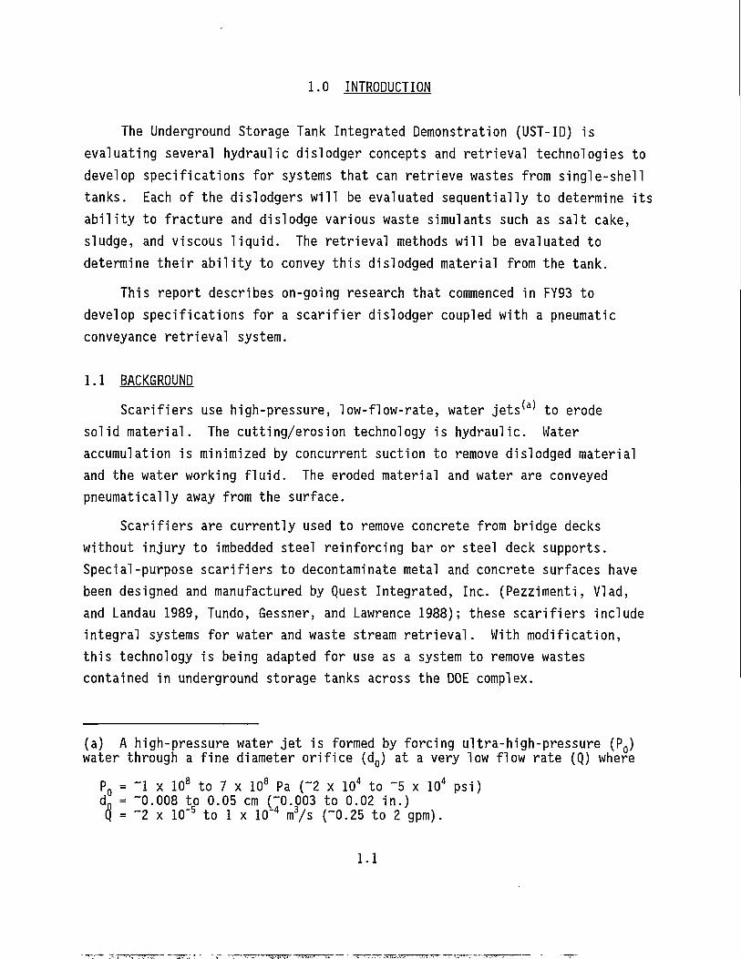
1.0 INTRODUCTION
The Underground Storage Tank Integrated Demonstration (UST-ID) is evaluating several hydraulic dislodger concepts and retrieval technologies to develop specifications for systems that can retrieve wastes from single-shell tanks. Each of the dislodgers will be evaluated sequentially to determine its ability to fracture and dislodge various waste simulants such as salt cake, sludge, and viscous liquid. The retrieval methods will be evaluated to determine their ability to convey this dislodged material from the tank.
This report describes on-going research that commenced in FY93 to develop specifications for a scarifier dislodger coupled with a pneumatic conveyance retrieval system.
1.1 BACKGROUND Scarifiers use high-pressure, low-flow-rate, water jets ( a ) to erode
solid material. The cutting/erosion technology is hydraulic. Water accumulation is minimized by concurrent suction to remove dislodged material and the water working fluid. The eroded material and water are conveyed pneumatically away from the surface.
Scarifiers are currently used to remove concrete from bridge decks without injury to imbedded steel reinforcing bar or steel deck supports. Special-purpose scarifiers to decontaminate metal and concrete surfaces have been designed and manufactured by Quest Integrated, Inc. (Pezzimenti, VIad, and Landau 1989, Tundo, Gessner, and Lawrence 1988); these scarifiers include integral systems for water and waste stream retrieval. With modification, this technology is being adapted for use as a system to remove wastes contained in underground storage tanks across the DOE complex.
(a) A high-pressure water jet is formed by forcing ultra-high-pressure (P0) water through a fine diameter orifice (d0) at a very low flow rate (Q) where
P 0 = ~1 x 10 8 to 7 x 10 8 Pa ("2 x 10 4 to ~5 x 10 4 psi) d D = "0.008 to 0.05 cm ("0.003 to 0.02 in.) Q = "2 x 10"5 to 1 x 10"4 m3/s ("0.25 to 2 gpm).
1.1
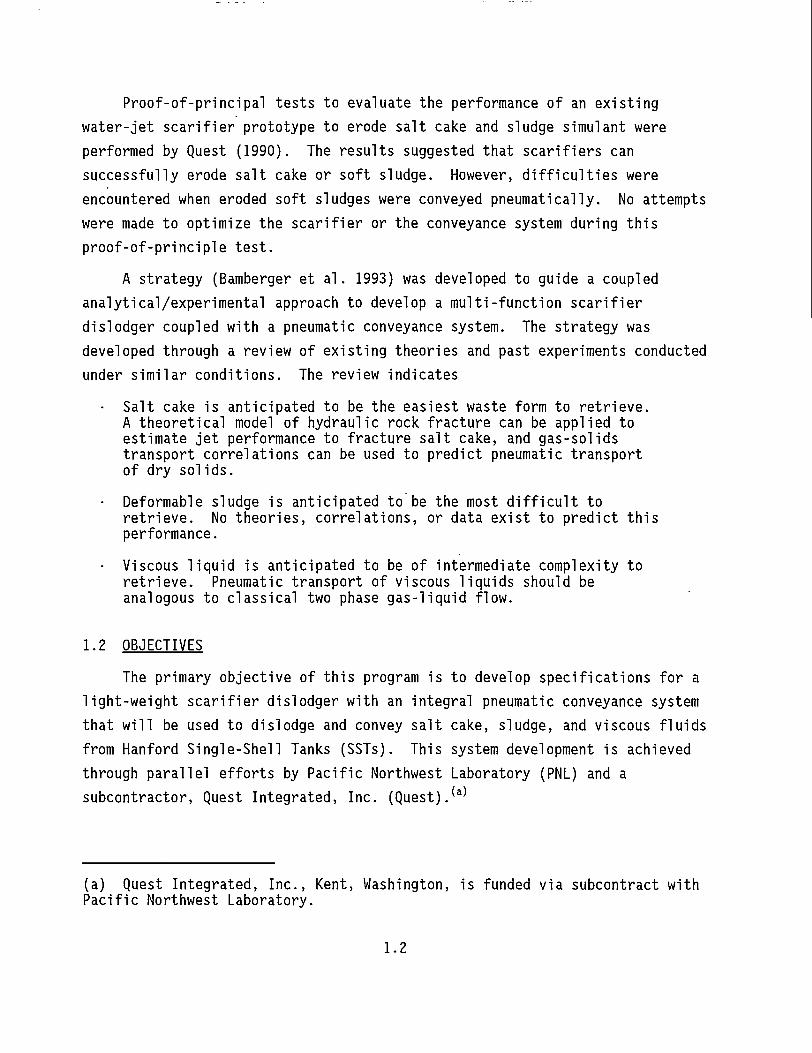
Proof-of-principal tests to evaluate the performance of an existing water-jet scarifier prototype to erode salt cake and sludge simulant were performed by Quest (1990). The results suggested that scarifiers can successfully erode salt cake or soft sludge. However, difficulties were encountered when eroded soft sludges were conveyed pneumatically. No attempts were made to optimize the scarifier or the conveyance system during this proof-of-principle test.
A strategy (Bamberger et al. 1993) was developed to guide a coupled analytical/experimental approach to develop a multi-function scarifier dislodger coupled with a pneumatic conveyance system. The strategy was developed through a review of existing theories and past experiments conducted under similar conditions. The review indicates
Salt cake is anticipated to be the easiest waste form to retrieve. A theoretical model of hydraulic rock fracture can be applied to estimate jet performance to fracture salt cake, and gas-solids transport correlations can be used to predict pneumatic transport of dry solids.
• Deformable sludge is anticipated to be the most difficult to retrieve. No theories, correlations, or data exist to predict this performance.
• Viscous liquid is anticipated to be of intermediate complexity to retrieve. Pneumatic transport of viscous liquids should be analogous to classical two phase gas-liquid flow.
1.2 OBJECTIVES
The primary objective of this program is to develop specifications for a light-weight scarifier dislodger with an integral pneumatic conveyance system that will be used to dislodge and convey salt cake, sludge, and viscous fluids from Hanford Single-Shell Tanks (SSTs). This system development is achieved through parallel efforts by Pacific Northwest Laboratory (PNL) and a subcontractor, Quest Integrated, Inc. (Quest).(a)
(a) Quest Integrated, Inc., Kent, Washington, is funded via subcontract with Pacific Northwest Laboratory.
1.2
'The integrated scarifier/conveyance technology will be adapted to • operate efficiently to remove a variety of waste forms including
salt cake, sludge and viscous fluids • minimize total water accumulation in tanks by incorporating an
integral removal/conveyance system • maximize working fluid retrieval efficiency to limit accumulation • limit water use rate by use of high-energy, high-pressure water
jets • minimize the footprint of the scarifier unit • limit scarifier mass to between 100 Ibm and 200 Ibm to optimize
placement on robotic end effectors • achieve a waste retrieval rate of 4 ft3/nrin in salt cake ( a )
• maximize the solid loading permitted in the conveyance system • optimize the size of solid aggregates that can be transported by
the conveyance system • optimize the size of solid aggregates that are produced by the
scarifier • assure vertical lift capability for the conveyance system of up to
60 ft • design conveyance system resistant to plugging • consider replacing scarifier rotating jet nozzles with linear
motion jet nozzles to reduce potential entanglement with in-tank hardware. The research objective will be accomplished through a multi-year
analytical and experimental investigation consisting of sequential experimental phases:
• Phase 1: Conduct ideal system performance evaluation with homogeneous simulants with horizontal, flat, surface contour. For
(a) Based on a retrieval rate of 1 ft3/min a single-shell tank containing 15 ft of salt cake would require 46 days (1104 hr) of continuous operation. With a retrieval rate of 4 ft3/min the retrieval time would decrease to 11.5 days (276 hr).
1.3
the scarifier and pneumatic conveyance investigations the Phase 1 experiments are separated into two subphases. 1A: Separate-effects experiments to optimize scarifier and conveyance
systems IB: Integrated experiments with a combined scarifier/pneumatic
conveyance system to investigate combined operation • Phase 2: Conduct integrated system experiments with non-
homogeneous simulants and contoured surfaces. All the dislodger evaluations will involve two subphases. 2A: Evaluate retrieval of homogeneous simulants with free surface
contours to model actual in-tank uneven surfaces. 2B: Evaluate retrieval of heterogeneous simulants that include veins of
other waste types, for example, salt cake with inclusions of sludge or viscous liquid.
• Phase 3: Conduct integrated system experiments with simulants that model in-tank debris such as tapes and pipes and edge effects such as the proximity of a tank wall, pipe, or large component.
• Phase 4: Conduct integrated system experiments to characterize performance during potential failure modes, such as power outages or conditions that cause system plugging, to determine the ability of the system to recover from upset conditions. These experimental phases provide the basis for parametric experiments
required to define system operation over a range of anticipated operating conditions. In addition they provide data to address key performance aspects. The data can be used to define the mining strategy for system deployment. Parameters that are important to this strategy are the inter-related stand-off distance of the dislodger and the jet depth of cut as well as the quality of the "machined surface," the waste surface remaining after a scarifier pass. The parametric data will be used to provide design specifications for the system. This data will define the dimensions, capacities and requirements for the waste dislodging and conveyance system. System performance data will also define the dynamic loads for the scarifier and pneumatic conveyance.
1.3 SCOPE In FY93 initial investigations were started to develop data to define
the performance of the combined dislodger and transport system via separate-effects experiments, Phase 1A. The development for scarifier and pneumatic
1.4
conveyance progressed at differing paces based on the availability of test fixtures.
For the scarifier, scope included 1) develop test plan for the scarifier separate-effects experiments 2) conduct separate-effects experiments to investigate the ability of a
single jet to fracture and dislodge waste 3) conduct multiple-jet experiments to investigate the effects of jet
interactions to enhance fracture and dislodging 4) initiate experiments to investigate jet secondary motion 5) initiate specifications for a multiple-jet scarifier head to be
integrated with the pneumatic conveyance system for use during the integrated-effects experiments. For pneumatic conveyance, scope included
1) define the scaling parameters that govern pneumatic transport of moist solids
2) develop test plan for pneumatic conveyance separate-effects experiments 3) design and construct pneumatic conveyance test fixture 4) investigate instrumentation strategies appropriate for monitoring
integrated scarifier/conveyance performance. The scarifier development is described in Section 3; pneumatic
conveyance development is described in Section 4. Preliminary system specifications are listed in Section 5. FY94 plans are summarized in Section 6.
1.5
2.0 CONCLUSIONS AND RECOMMENDATIONS
2.1 CONCLUSIONS • Ultra-high-pressure water-jet based scarifier dislodging technology
appears to be capable of meeting the waste fracture and dislodging rates required (4 ft3/min) for single-shell tank retrieval for both salt cake and sludge waste forms, although more development is required to verify this.
• A pneumatic-conveyance test plan and test fixture have been developed to produce correlations defining conveyance of the dislodged waste simulant.
2.1.1 Single-Jet Experimental Results The single-jet experiments investigated interactions between jets and
simulants. The following conclusions can be drawn from the experiments: • Removal efficiency increased with hydraulic horsepower, and water
cutting efficiency increased with jet pressure. The maximum material removal rate was obtained with the larger diameter jet at the higher pressure for both the round and fan jets.
• Fan jets appear more effective than round jets for dislodging either simulant, at any combination of angle, pressure, and velocity. 2.1.1.1 Salt-Cake Simulant Test Results The following conclusions can be drawn from the salt cake simulant tests
for the round and fan jets: Round-Jet Test Results
• Round jets cut clean and narrow kerfs into the simulant to a depth approximately proportional to hydraulic horsepower (the square of the orifice diameter) and inversely proportional to effective traverse speed, a phenomena commonly found in liquid-jet cutting.
• Kerf widths were approximately 4 times the jet diameter. • Erosion was the primary material removal mechanism, with virtually
no secondary fracturing or material dislodging which could be attributed to the jet pass.
• Removed particles were observed to be fines on the order of 0.025 in. in diameter and smaller.
2.1
• Volumetric removal efficiency was relatively low for round-jet fracture of salt cake. When the volumetric removal efficiency is divided by the hydraulic horsepower, the results are similar for all test conditions. This is attributed to the dominance of an erosion removal mechanism.
• The maximum water volume efficiency occurs at the highest jet pressure. This is the effect of the hydraulic horsepower per unit area of the water jet increasing with pressure.
Fan-Jet Test Results
• Two mechanisms dominated fan jet removed: erosion and solid fracture.
• Primary erosion produced dislodged fines of the same size scale as those under the influence of the round jet. The fan jet preferentially erodes the surface in response to local small-scale variations in salt-cake properties. This erosion process produces a non-uniform rough surface. The varying velocity vector components across the fan result in a randomized jet/surface reflection which effectively fractures material off the roughened surface and increases the volumetric efficiency of this jet shape.
• Material removal rate was higher with the fan jets than the corresponding round jets. This was the result of the secondary fracture mechanism, which contributed to total material dislodged.
2.1.1.2 Sludge-Simulant Test Results
The sludge responded differently under the influence of the round and fan jets.
Round-Jet Test Results
• The round jet sliced cleanly through the sludge simulant which slumped under its own weight behind the jet to close the kerf below approximately 2-in. depth. The larger-diameter round jet pierced to a depth of at least 10 in. in the sludge, but had lost most of it's energy at that depth.
• The sludge was not displaced appreciably by either of the round jets; it tended rather to absorb the jet water and liquefy.
Fan-Jet Test Results
• Fan jets were effective in dislodging sludge.
• Sludge responded to the fan jets more in terms of bulk displacement than erosion. The distributed jet pressure appeared to push, or
2.2
shape, a trench through the sludge with a size proportional to the swept area within the fan.
• The larger fan jet cleared sludge to a distance of approximately 5 in. in front of the nozzle.
• The sludge displaced by the fan jets tended to be lifted or rolled above the surface—creating ribbons of sludge, or be pushed in front of the jet thus forcing a mound of otherwise undisturbed neighboring sludge to rise from the surface.
• Removal efficiency was higher at the lower traverse speeds. Lower traverse speeds give the jet a longer effective jet dwell and the opportunity to remove a greater material mass. Also the effective stand-off distance increases as material is removed. If removal efficiency increases as a function of stand-off distance, the overall efficiency can increase with decreasing traverse speed.
2.1.2 Multiple-Jet Experimental Results The multiple-jet experiments are in progress. Two outcomes are desired:
to produce the required particle size distribution and to direct dislodged waste upward and into the transport system entrance. The following conclusions can be drawn from the results to date: • Fan/fan-jet combination was judged to be superior for sludge
dislodging. • For multiple passes, the average volume of material removed per
pass was larger with multiple passes than with a single pass over a new surface. Second-layer removal, at a lower z-axis position in the simulant, is likely to produce greater volumetric removal rates that those obtained in the first-layer removal.
• The round/fan-jet and round/round-jet combinations show promise with a dislodger configuration that incorporates secondary motion.
• The fan/fan-jet combination may prove acceptable in a system that does not require secondary motion and may also perform relatively well in the presence of mixed waste. 2.1.2.1 Sludge-Simulant Test Results
• Fan/fan-jet combination was judged to be superior for sludge dislodging.
2.3
2.1.2.2 Salt-Cake Simulant Test Results • For multiple passes, the average volume of material removed per
pass was larger with multiple passes than with a single pass over a new surface. Second layer removal, at a lower z-axis position in the simulant, is likely to produce greater volumetric removal rates that those obtained in the first layer removed.
•. In the round/fan-jet combination, kerf depth progressively deepened with each successive pass. The kerf stabilized at a limiting value.
• The round jet cuts a narrow deep kerf, while the fan jet cuts a relatively wide and shallow kerf. When the round/fan-jet combination is used and multiple passes are incorporated, the round jet separates thin webs of material from the simulant and the fan jet follows, pulverizing the thin web.
• The round/fan-jet combination shows promise with a dislodger configuration that incorporates secondary motion.
• The round/round-jet combination appears to remove large amounts of material due to the greater power intensity. The jets cut an hourglass shaped kerf.
• The round/round-jet kerf shape lends itself to a secondary motion device.
• The fan/fan-jet combination cuts a relatively wide and shallow kerf.
• The fan/fan-jet combination may prove acceptable in a system that does not have a secondary motion and may also perform relatively well in the presence of mixed waste. Multiple-jet experimental data is still being analyzed to determine
which combinations should be investigated with secondary motion. Several, types of secondary motion can be implemented into a scarifier: rotary motion, oscillatory motion, or multiple stationary jets that fire linearly. The secondary motion that creates the most efficient motion may not be rotary motion. A reciprocating linear motion has an advantage that none of the operating time is spent waiting for the jet to return to the location of the new material. The effect of traverse velocity will also be investigated during the secondary-motion experiments.
2.4
2.1.3 Pneumatic-Conveyance Development The integrated scarifier/conveyance test fixture system was sized to
evaluate waste retrieval at a rate of 1 to 2 ft3/nrin.(a) A scaling methodology was developed to investigate higher transport rates of 4 or 8 ft3/min.
2.1.3.1 Scaling Methodology To investigate the effect of varying transport line diameter a scaling
methodology has been developed. A dimensional analysis was conducted to quantify the effects of increasing retrieval rate and pipe diameter. The dimensional analysis showed that the ratio of mass flow rate of particulate to the mass flow rate of gas is a function of seven parameters.
The effect of pipe diameter appears in two of these parameters, the Reynolds number and the Stokes number. Scaling to larger pipe diameters would affect these two variables. One would not expect that a slightly higher Reynolds number of a non-transition regime would have a significant effect. A larger Stokes number would lead to a longer acceleration length which would be significant if the acceleration distance is comparable to the pipe length.
2.1.3.2 Test Plan The pneumatic transport test plan was developed to provide mechanistic
performance data to develop performance correlations for retrieval. Pneumatic transport usually concerns the transport of dry solids in air. The transport associated with single-shell tank retrieval will involve transport of wet material. The waste is wet and cutting liquid from the scarifier will further lubricate the waste. b ) A test plan was developed to investigate transport of dry and wet wastes to investigate the effects of particle diameter, pipe
(a) An existing blower was incorporated to power the pneumatic conveyance test fixture. The size of this blower dictated the initial system through put. If required the blower can be augmented to evaluate greater through put. (b) Westinghouse Hanford Company Soft Waste Dislodging Investigations showed that transport is enhanced when a small amount of water sprayed into the conveyance inlet is used to lubricate the conveyance line.
2.5
diameter, solids loading, air flow rate, and liquid addition for the simulant types.
2.1.3.3 Pneumatic-Conveyance Test Fixture
A pneumatic conveyance test fixture was designed and is under construction in the PNL 336 Building at Hanford. The test fixture is instrumented to develop mechanistic pressure drop and transport data for waste retrieval during both pneumatic conveyance separate-effects experiments and when the system is integrated with the scarifier. The test fixture will permit tests at two pipe diameters: 3 in. and 4 in. Initial tests will be conducted over a conveyance length of 20 ft. In its current location, the system can be lengthened to prototypic length of 60 ft by addition of pipe segments into an existing pit in the building. These experiments will be conducted in FY94.
2.2 RECOMMENDATIONS
The scarifier/conveyance investigation began in FY93 with the objective to develop the scarifier ultra-high-pressure jet dislodger coupled with pneumatic transport retrieval for remediation of single-shell tanks. In FY94 the task objective has been expanded to develop a fundamental understanding of the mechanics of dislodging, mobilizing and conveying waste for the two waste dislodging and conveyance system combinations:
• scarifier (ultra-high-pressure water jet: 40,000 to 50,000 psi) coupled with pneumatic transport
• miner (medium-pressure water jet: 5,000 to 11,000 psi) coupled with jet pump transport
to
• develop parametric data to define and resolve open issues critical to system design and specification
recommend specifications for a design that can be tested in the integrated test bed and deployed in a waste tank environment.
2.6
3.0 SCARIFIER DEVELOPMENT
The objective of the scarifier separate-effects experiments is to identify scarifier parameter ranges that will dislodge the three waste forms (salt cake, sludge, and viscous liquids) into discrete particulate that can be efficiently mobilized and transported pneumatically. This information will be used to design a scarifier configuration to be used during the integrated-effects experiments when the combined dislodging and conveyance approach is investigated. Key parameters that must be determined are an optimum jet (diameter, shape, pressure, number, configuration, and translation rate) for fracturing and dislodging the multiple waste forms and an initial containment shroud configuration.
Scarifier separate-effects investigations are divided into four parts: 1) Single-jet experiments: to investigate the ability of a single jet to
fracture and dislodge waste to evaluate jet parameters that influence the size of particulate and to recommend parameter ranges for the multiple-jet experiments.
2) Multiple-jet experiments: to investigate the effects of jet interaction to enhance waste fracture and dislodging to recommend parameter ranges for secondary-motion experiments.
3) Secondary-motion experiments: to investigate the ability of secondary motion to enhance waste dislodging and mobilization to recommend secondary motion to investigate during integrated-effects experiments.
4) Shroud development: to investigate shroud configurations that enhance particulate entrainment into the pneumatic transport line.
3.1 PARAMETERS THAT INFLUENCE SCARIFICATION The parameters that affect scarification can be classified according to
jet properties, material properties, and scarifier process parameters. These parameters and their anticipated ranges are summarized in Table 3.1. In addition to encasing the high pressure jet, the scarifier shroud links the scarifier to the pneumatic transport line. The shroud shape, aerodynamic properties, and interaction with particulate influence pneumatic conveyance. The shroud parameters will be investigated during the integrated-effects experiments.
3.1
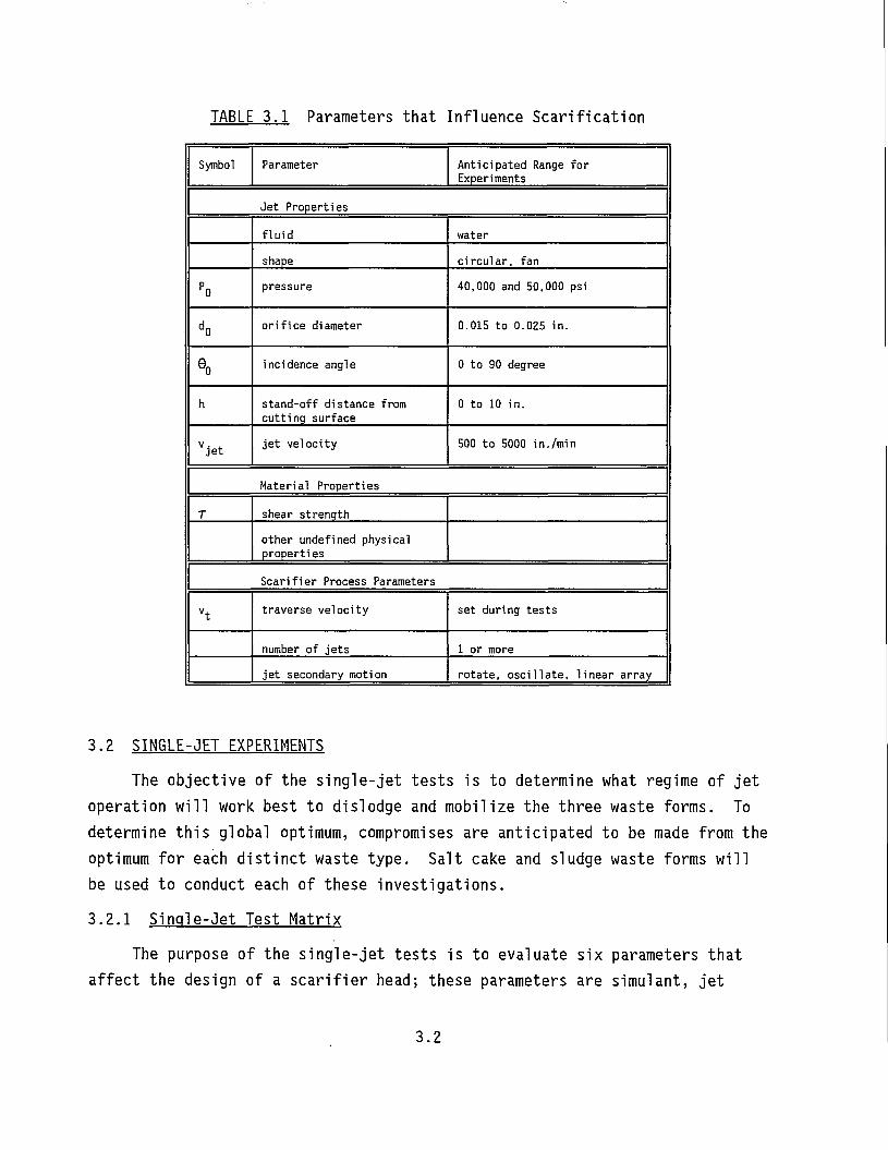
TABLE 3.1 Parameters that Influence Scarification
Symbol Parameter Anticipated Range for Experiments
Jet Properties
fluid water shape circular, fan
P0 pressure 40,000 and 50,000 psi
d0 orifice diameter 0.015 to 0.025 in.
80 incidence angle 0 to 90 degree
h stand-off distance from cutting surface
0 to 10 in.
Vjet jet velocity 500 to 5000 in./min
Material Properties
T shear strength other undefined physical properties
Scarifier Process Parameters
vt traverse velocity set during tests
number of jets 1 or more jet secondary motion rotate, oscillate, linear array
3.2 SINGLE-JET EXPERIMENTS The objective of the single-jet tests is to determine what regime of jet
operation will work best to dislodge and mobilize the three waste forms. To determine this global optimum, compromises are anticipated to be made from the optimum for each distinct waste type. Salt cake and sludge waste forms will be used to conduct each of these investigations. 3.2.1 Single-Jet Test Matrix
The purpose of the single-jet tests is to evaluate six parameters that affect the design of a scarifier head; these parameters are simulant, jet
3.2
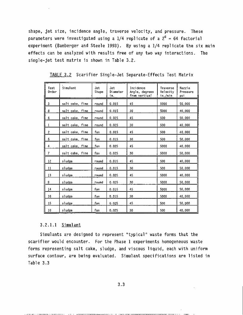
shape, jet size, incidence angle, traverse velocity, and pressure. These parameters were investigated using a 1/4 replicate of a 2 6 = 64 factorial experiment (Bamberger and Steele 1993). By using a 1/4 replicate the six main effects can be analyzed with results free of any two way interactions. The single-jet test matrix is shown in Table 3.2.
TABLE 3.2 Scarifier Single-Jet Separate-Effects Test Matrix
Test Order
Simulant Jet Shape
Jet Diameter in.
Incidence Angle, degrees from vertical
Traverse Velocity in./min
Nozzle Pressure psi
3 salt cake, fine round 0.015 45 5000 50,000
8 salt cake, fine round 0.015 30 5000 40,000
6 salt cake, fine round 0.025 45 500 50.000
1 salt cake, fine round 0.025 30 500 40.000
2 salt cake, fine fan 0.015 45 500 40,000
5 salt cake, fine fan 0.015 30 500 50,000
4 salt cake, fine fan 0.025 45 5000 40,000
7 salt cake, fine fan 0.025 30 5000 50,000
12 sludge round 0.015 45 500 40.000
11 sludge round 0.015 30 500 50,000
13 sludge round 0.025 45 5000 40,000
9 sludge round 0.025 30 5000 50,000
14 sludge fan 0.015 45 5000 50,000
16 sludge fan 0.015 30 5000 40.000
15 sludge fan 0.025 45 500 50,000
10 sludge fan 0.025 30 500 40,000
3.2.1.1 Simulant Simulants are designed to represent "typical" waste forms that the
scarifier would encounter. For the Phase 1 experiments homogeneous waste forms representing salt cake, sludge, and viscous liquid, each with uniform surface contour, are being evaluated. Simulant specifications are listed in Table 3.3
3.3
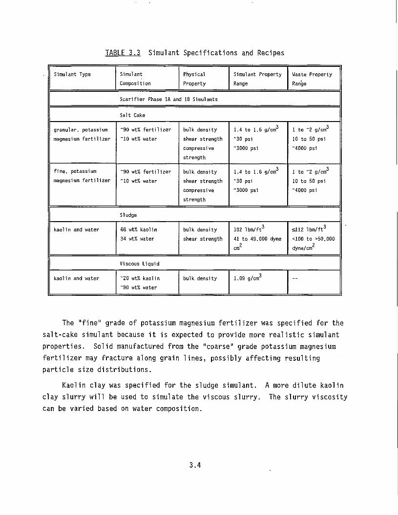
TABLE 3.3 Simulant Specifications and Recipes
Simulant Type Simulant Physical Simulant Property Waste Property Composition Property Range Range
Scarifier Phase 1A and IB Simulants
Salt Cake
granular, potassium ~90 wt% fertilizer bulk density 1.4 to 1.6 g/cm3 1 to "2 g/cm3
magnesium fertilizer "10 wt% water shear strength "30 psi 10 to 50 psi compressive strength
"3000 psi "4000 psi
fine, potassium ~90 wt% fertilizer bulk density 1.4 to 1.6 g/cm3 1 to "2 g/cm3
magnesium fertilizer "10 wt% water shear strength "30 psi 10 to 50 psi compressive strength
"3000 psi "4000 psi
Sludge
kaolin and water 66 wt% kaoli n bulk density 102 lbm/ft3 S112 lbm/ft3
34 wt% water shear strength 41 to 49,000 dyne 2
cm
<100 to >50,000 dyne/cm
Viscous Liquid
kaoli n and water "20 wt% kaolin "80 wt% water
bulk density 1.09 g/cm3 —
The "fine" grade of potassium magnesium fertilizer was specified for the salt-cake simulant because it is expected to provide more realistic simulant properties. Solid manufactured from the "coarse" grade potassium magnesium fertilizer may fracture along grain lines, possibly affecting resulting particle size distributions.
Kaolin clay was specified for the sludge simulant. A more dilute kaolin clay slurry will be used to simulate the viscous slurry. The slurry viscosity can be varied based on water composition.
3.4
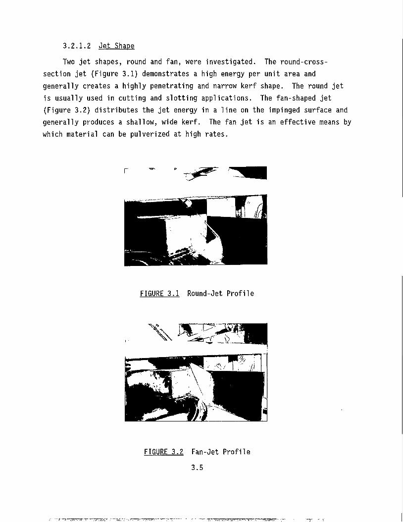
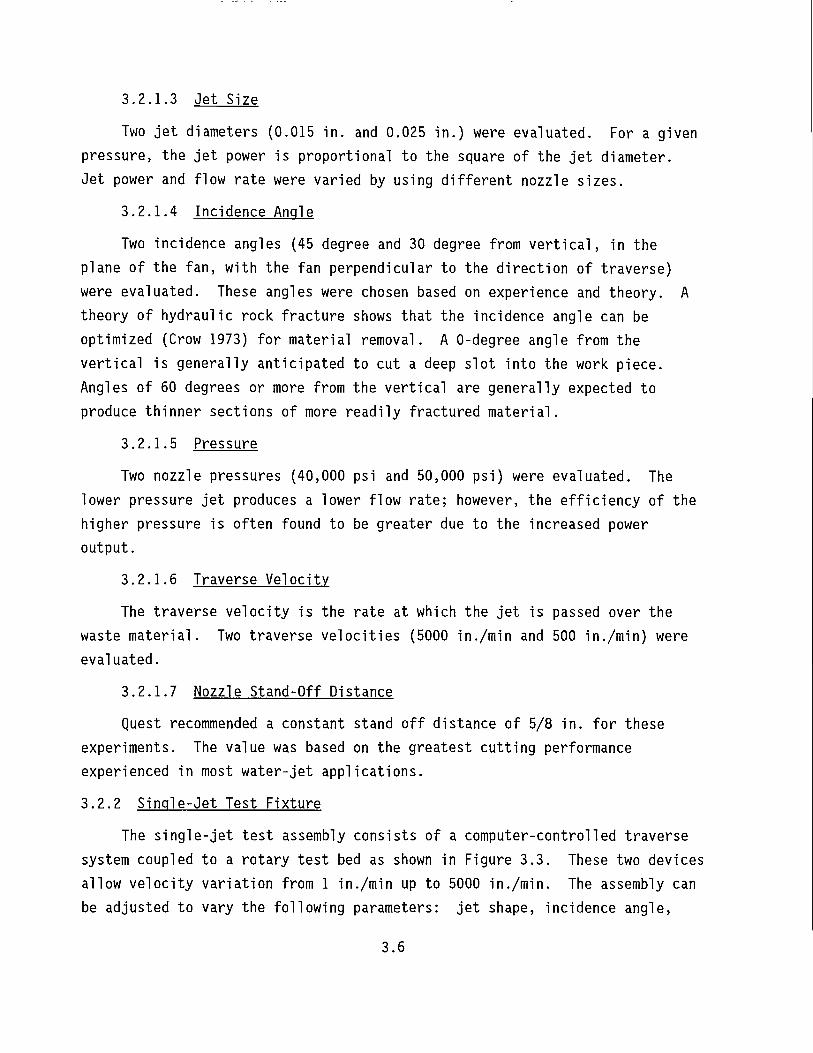
3.2.1.2 Jet Shape Two jet shapes, round and fan, were investigated. The round-cross-
section jet (Figure 3.1) demonstrates a high energy per unit area and generally creates a highly penetrating and narrow kerf shape. The round jet is usually used in cutting and slotting applications. The fan-shaped jet (Figure 3.2) distributes the jet energy in a line on the impinged surface and generally produces a shallow, wide kerf. The fan jet is an effective means by which material can be pulverized at high rates.
FIGURE 3.1 Round-Jet Profile
FIGURE 3.2 Fan-Jet Profile
3.5
3.2.1.3 Jet Size
Two jet diameters (0.015 in. and 0.025 in.) were evaluated. For a given pressure, the jet power is proportional to the square of the jet diameter. Jet power and flow rate were varied by using different nozzle sizes.
3.2.1.4 Incidence Angle
Two incidence angles (45 degree and 30 degree from vertical, in the plane of the fan, with the fan perpendicular to the direction of traverse) were evaluated. These angles were chosen based on experience and theory. A theory of hydraulic rock fracture shows that the incidence angle can be optimized (Crow 1973) for material removal. A 0-degree angle from the vertical is generally anticipated to cut a deep slot into the work piece. Angles of 60 degrees or more from the vertical are generally expected to produce thinner sections of more readily fractured material.
3.2.1.5 Pressure
Two nozzle pressures (40,000 psi and 50,000 psi) were evaluated. The lower pressure jet produces a lower flow rate; however, the efficiency of the higher pressure is often found to be greater due to the increased power output.
3.2.1.6 Traverse Velocity
The traverse velocity is the rate at which the jet is passed over the waste material. Two traverse velocities (5000 in./min and 500 in./min) were evaluated.
3.2.1.7 Nozzle Stand-Off Distance
Quest recommended a constant stand off distance of 5/8 in. for these experiments. The value was based on the greatest cutting performance experienced in most water-jet applications.
3.2.2 Single-Jet Test Fixture
The single-jet test assembly consists of a computer-controlled traverse system coupled to a rotary test bed as shown in Figure 3.3. These two devices allow velocity variation from 1 in./min up to 5000 in./min. The assembly can be adjusted to vary the following parameters: jet shape, incidence angle,
3.6
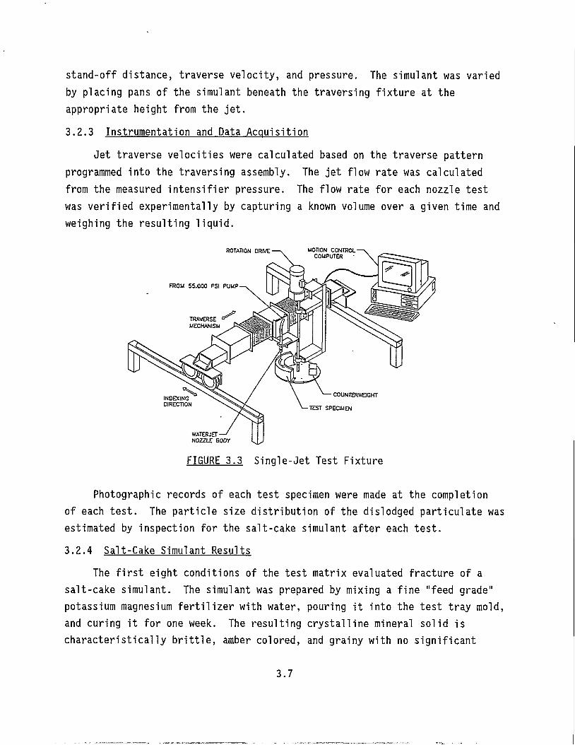
stand-off distance, traverse velocity, and pressure. The simulant was varied by placing pans of the simulant beneath the traversing fixture at the appropriate height from the jet. 3.2.3 Instrumentation and Data Acquisition
Jet traverse velocities were calculated based on the traverse pattern programmed into the traversing assembly. The jet flow rate was calculated from the measured intensifier pressure. The flow rate for each nozzle test was verified experimentally by capturing a known volume over a given time and weighing the resulting liquid.
FIGURE 3.3 Single-Jet Test Fixture
Photographic records of each test specimen were made at the completion of each test. The particle size distribution of the dislodged particulate was estimated by inspection for the salt-cake simulant after each test. 3.2.4 Salt-Cake Simulant Results
The first eight conditions of the test matrix evaluated fracture of a salt-cake simulant. The simulant was prepared by mixing a fine "feed grade" potassium magnesium fertilizer with water, pouring it into the test tray mold, and curing it for one week. The resulting crystalline mineral solid is characteristically brittle, amber colored, and grainy with no significant
3.7
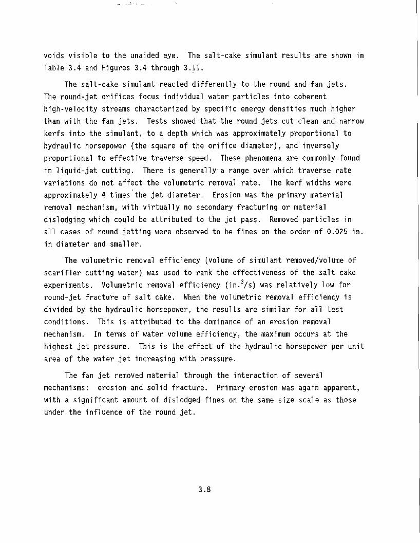
voids visible to the unaided eye. The salt-cake simulant results are shown in Table 3.4 and Figures 3.4 through 3.11.
The salt-cake simulant reacted differently to the round and fan jets. The round-jet orifices focus individual water particles into coherent high-velocity streams characterized by specific energy densities much higher than with the fan jets. Tests showed that the round jets cut clean and narrow kerfs into the simulant, to a depth which was approximately proportional to hydraulic horsepower (the square of the orifice diameter), and inversely proportional to effective traverse speed. These phenomena are commonly found in liquid-jet cutting. There is generally a range over which traverse rate variations do not affect the volumetric removal rate. The kerf widths were approximately 4 times the jet diameter. Erosion was the primary material removal mechanism, with virtually no secondary fracturing or material dislodging which could be attributed to the jet pass. Removed particles in all cases of round jetting were observed to be fines on the order of 0.025 in. in diameter and smaller.
The volumetric removal efficiency (volume of simulant removed/volume of scarifier cutting water) was used to rank the effectiveness of the salt cake experiments. Volumetric removal efficiency (in.3/s) was relatively low for round-jet fracture of salt cake. When the volumetric removal efficiency is divided by the hydraulic horsepower, the results are similar for all test conditions. This is attributed to the dominance of an erosion removal mechanism. In terms of water volume efficiency, the maximum occurs at the highest jet pressure. This is the effect of the hydraulic horsepower per unit area of the water jet increasing with pressure.
The fan jet removed material through the interaction of several mechanisms: erosion and solid fracture. Primary erosion was again apparent, with a significant amount of dislodged fines on the same size scale as those under the influence of the round jet.
3.8
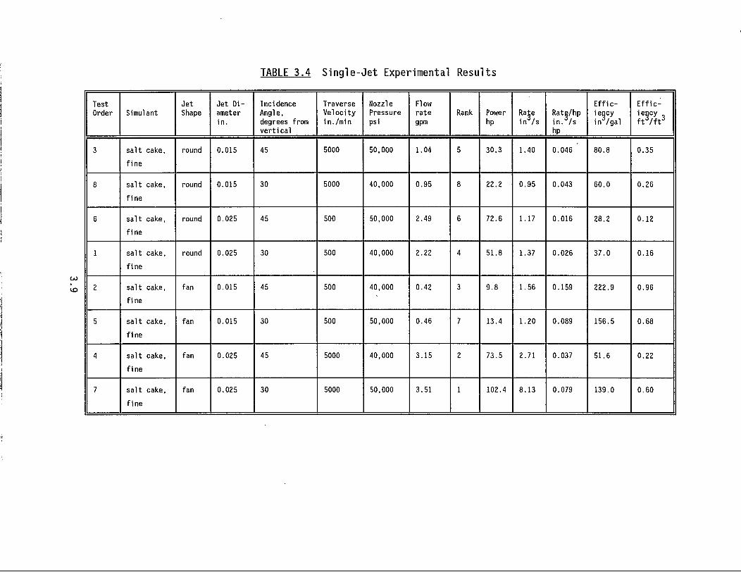
TABLE 3.4 Single-Jet Experimental Results
Test Order Simulant
Jet Shape
Jet Di ameter i n .
Incidence Angle, degrees from ver t i ca l
Traverse Veloci ty i n./mi n
Nozzle Pressure psi
Flow rate gpm
Rank Power hp
Rate inVs
Rate/hp i n . /s hp
E f f i c iency in /gal
E f f i c :
iency f r / f r
3 sal t cake,
f ine
round 0.015 45 5000 50,000 1.04 5 30.3 1.40 0.046 80.8 0.35
8 sa l t cake,
f ine
round 0.015 30 5000 40,000 0.95 8 22.2 0.95 0.043 60.0 0.26
6 sa l t cake,
f ine
round 0.025 45 500 50,000 2.49 6 72.6 1.17 0.016 28.2 0.12
1 sa l t cake,
f ine
round 0.025 30 500 40,000 2.22 4 51.8 1.37 0.026 37.0 0.16
2 sa l t cake,
f ine
fan 0.015 45 500 40,000 0.42 3 9.8 1.56 0.159 222.9 0.96
5 sa l t cake,
f ine
fan 0.015 30 500 50,000 0.46 7 13.4 1.20 0.089 156.5 0.68
4 sa l t cake,
f ine
fan 0.025 45 5000 40,000 3.15 2 73.5 2.71 0.037 51.6 0.22
7 sa l t cake,
f ine
fan 0.025 30 5000 50,000 3.51 1 102.4 8.13 0.079 139.0 0.60
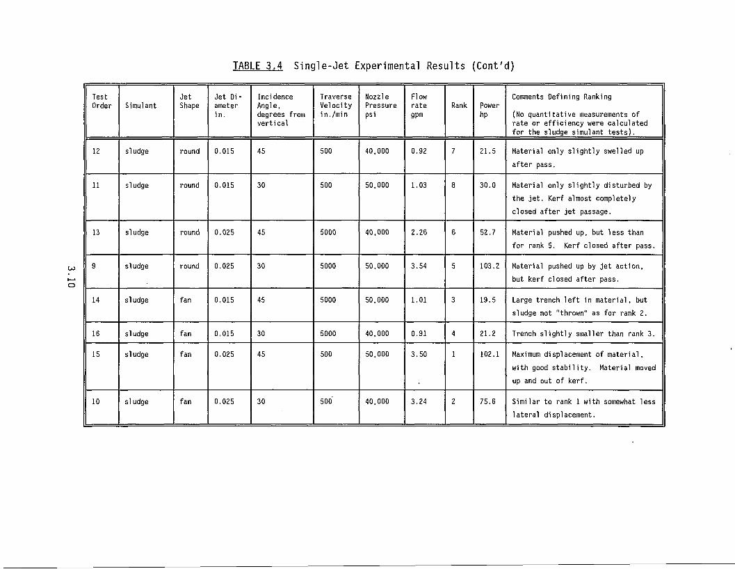
TABLE 3.4 Single-Jet Experimental Results (Cont'd)
Test Order Simulant
Jet Shape
Jet Diameter in.
Incidence Angle, degrees from vertical
Traverse Velocity in./min
Nozzle Pressure psi
Flow rate gpm
Rank Power hp
Comments Defining Ranking
(No quantitative measurements of rate or efficiency were calculated for the sludge simulant tests).
12 sludge round 0.015 45 500 40,000 0.92 7 21.5 Material only slightly swelled up after pass.
11 sludge round 0.015 30 500 50,000 1.03 8 30.0 Material only slightly disturbed by the jet. Kerf almost completely closed after jet passage.
13 sludge round 0.025 45 5000 40,000 2.26 6 52.7 Material pushed up, but less than for rank 5. Kerf closed after pass.
9 sludge round 0.025 30 5000 50,000 3.54 5 103.2 Material pushed up by jet action, but kerf closed after pass.
14 sludge fan 0.015 45 5000 50,000 1.01 3 19.5 Large trench left in material, but sludge not "thrown" as for rank 2.
16 sludge fan 0.015 30 5000 40,000 0.91 4 21.2 Trench slightly smaller than rank 3.
15 sludge fan 0.025 45 500 50,000 3.50 1 102.1 Maximum displacement of material, with good stability. Material moved up and out of kerf.
10 sludge fan 0.025 30 500' 40,000 3.24 2 75.6 Similar to rank 1 with somewhat less lateral displacement.
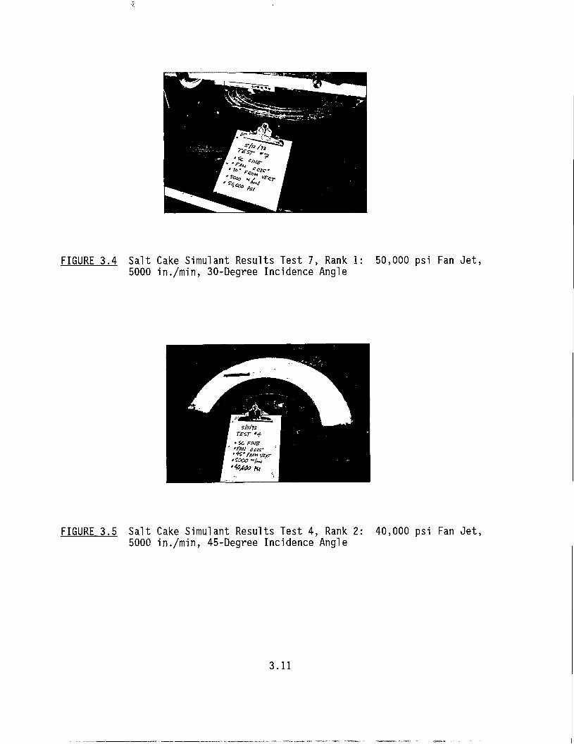
FIGURE 3.4 Salt Cake Simulant Results Test 7, Rank 1: 5000 in./min, 30-Degree Incidence Angle
50,000 psi Fan Jet,
FIGURE 3.5 Salt Cake Simulant Results Test 4, Rank 2: 5000 in./min, 45-Degree Incidence Angle
40,000 psi Fan Jet,
3.11
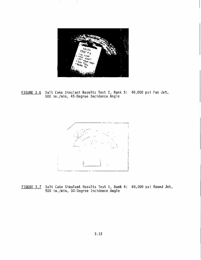
FIGURE 3.6 Salt Cake Simulant Results Test 2, Rank 3: 500 i n . /m in , 45-Degree Incidence Angle
40,000 psi Fan Jet,
FIGURE 3.7 Salt Cake Simulant Results Test 1, Rank 4: 500 in./min, 30-Degree Incidence Angle
40,000 psi Round Jet,
3.12
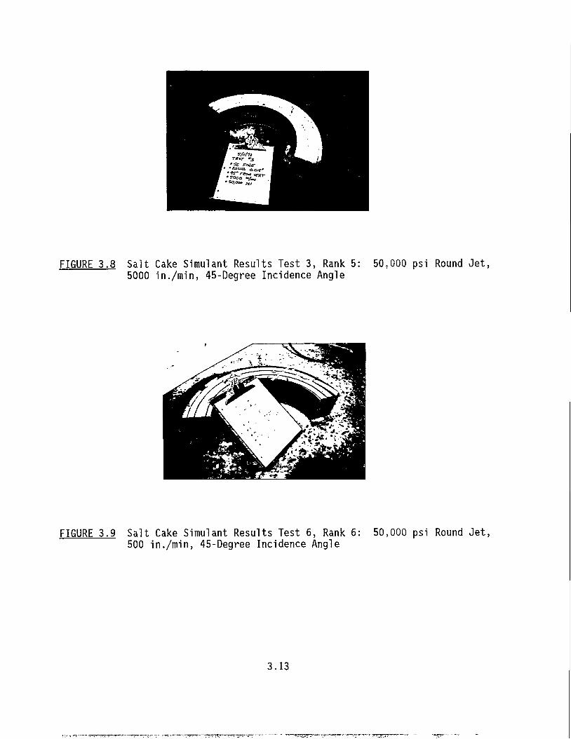
FIGURE 3.8 Salt Cake Simulant Results Test 3, Rank 5: 5000 in./min, 45-Degree Incidence Angle
50,000 psi Round Jet,
FIGURE 3.9 Salt Cake Simulant Results Test 6, Rank 6: 500 in./min, 45-Degree Incidence Angle
50,000 psi Round Jet,
3.13
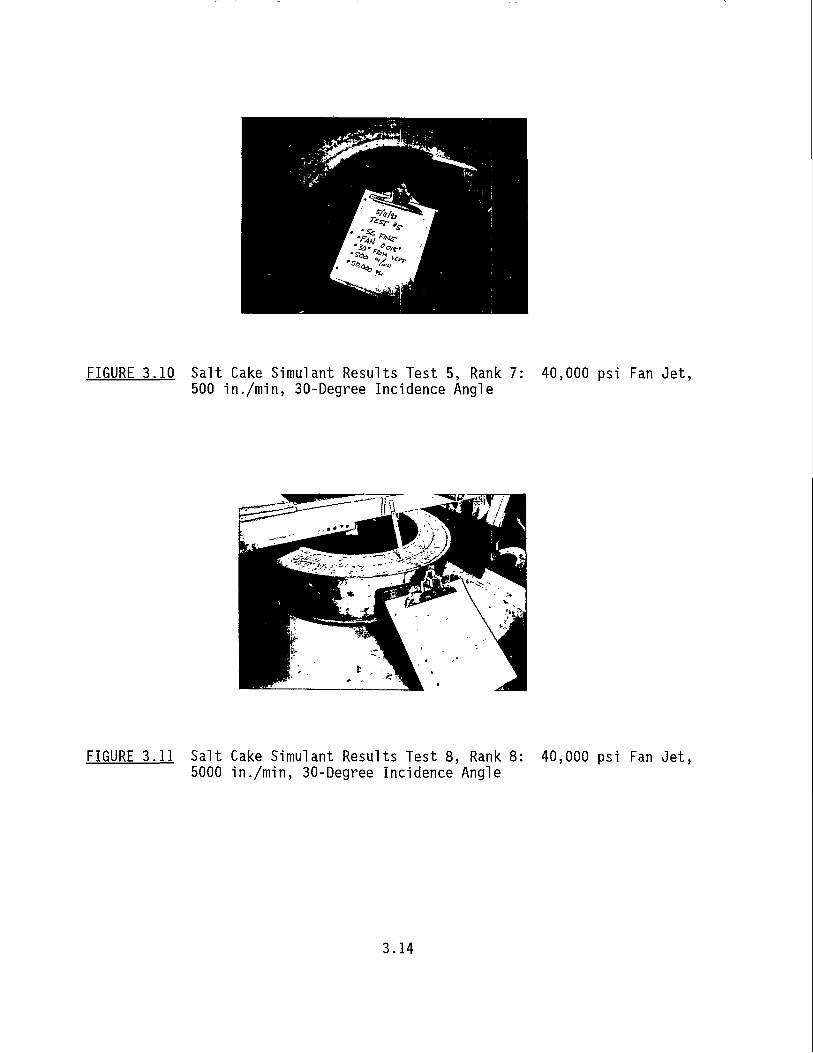
FIGURE 3.10 Salt Cake Simulant Results Test 5, Rank 7: 500 i n . /m in , 30-Degree Incidence Angle
40,000 psi Fan Jet,
FIGURE 3.11 Salt Cake Simulant Results Test 8, Rank 8: 5000 in./min, 30-Degree Incidence Angle
40,000 psi Fan Jet,
3.14
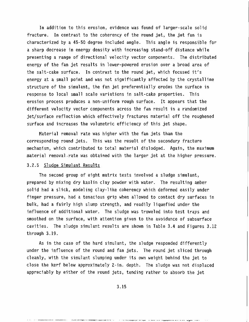
In addition to this erosion, evidence was found of larger-scale solid fracture. In contrast to the coherency of the round jet, the jet fan is characterized by a 45-50 degree included angle. This angle is responsible for a sharp decrease in energy density with increasing stand-off distance while presenting a range of directional velocity vector components. The distributed energy of the fan jet results in lower-powered erosion over a broad area of the salt-cake surface. In contrast to the round jet, which focused it's energy at a small point and was not significantly affected by the crystalline structure of the simulant, the fan jet preferentially erodes the surface in response to local small scale variations in salt-cake properties. This erosion process produces a non-uniform rough surface. It appears that the different velocity vector components across the fan result in a randomized jet/surface reflection which effectively fractures material off the roughened surface and increases the volumetric efficiency of this jet shape.
Material removal rate was higher with the fan jets than the corresponding round jets. This was the result of the secondary fracture mechanism, which contributed to total material dislodged. Again, the maximum material removal-rate was obtained with the larger jet at the higher pressure. 3.2.5 Sludge Simulant Results
The second group of eight matrix tests involved a sludge simulant, prepared by mixing dry kaolin clay powder with water. The resulting amber solid had a slick, modeling clay-like coherency which deformed easily under finger pressure, had a tenacious grip when allowed to contact dry surfaces in bulk, had a fairly high slump strength, and readily liquefied under the influence of additional water. The sludge was troweled into test trays and smoothed on the surface, with attention given to the avoidance of subsurface cavities. The sludge simulant results are shown in Table 3.4 and Figures 3.12 through 3.19.
As in the case of the hard simulant, the sludge responded differently under the influence of the round and fan jets. The round jet sliced through cleanly, with the simulant slumping under its own weight behind the jet to close the kerf below approximately 2-in. depth. The sludge was not displaced appreciably by either of the round jets, tending rather to absorb the jet
3.15
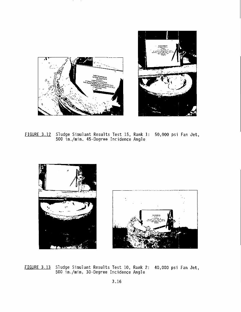
FIGURE 3.12 Sludge Simulant Results Test 15, Rank 1: 500 in./min, 45-Degree Incidence Angle
50,000 psi Fan Jet,
FIGURE 3.13 Sludge Simulant Results Test 10, Rank 2: 500 in./min, 30-Degree Incidence Angle
40,000 psi Fan Jet,
3.16
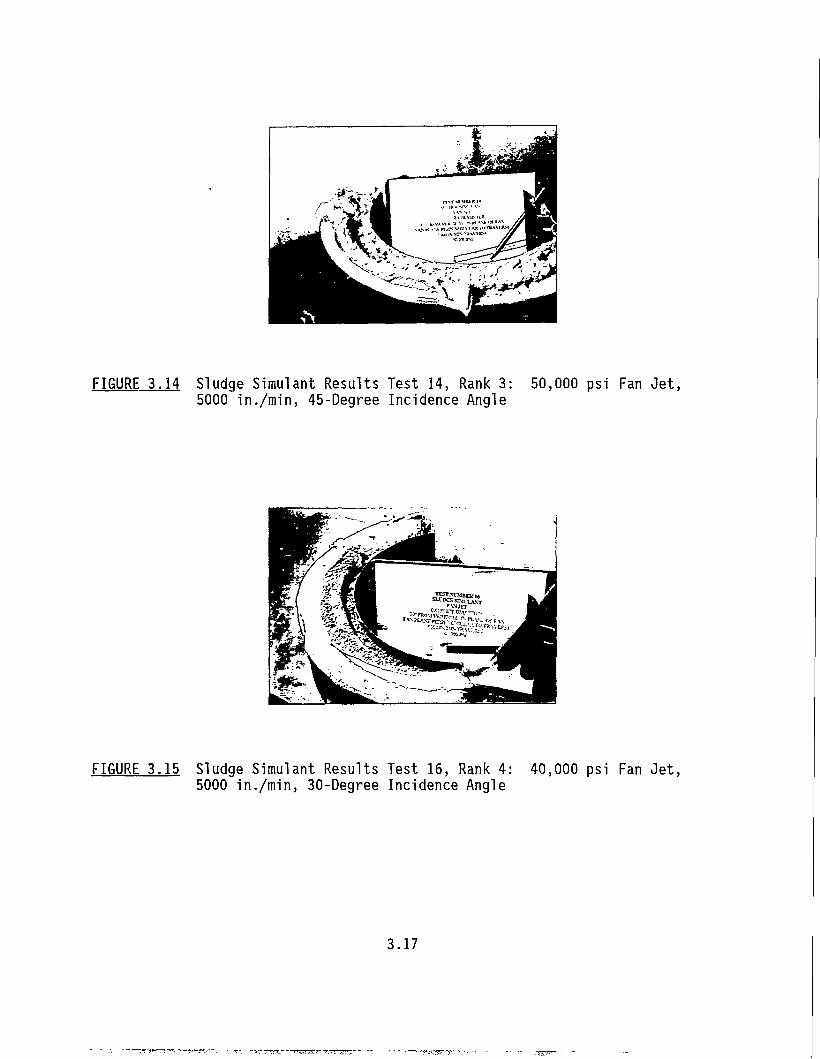
FIGURE 3.14 Sludge Simulant Results Test 14, Rank 3: 5000 in./min, 45-Degree Incidence Angle
50,000 psi Fan Jet,
FIGURE 3.15 Sludge Simulant Results Test 16, Rank 4: 5000 in./min, 30-Degree Incidence Angle
40,000 psi Fan Jet,
3.17
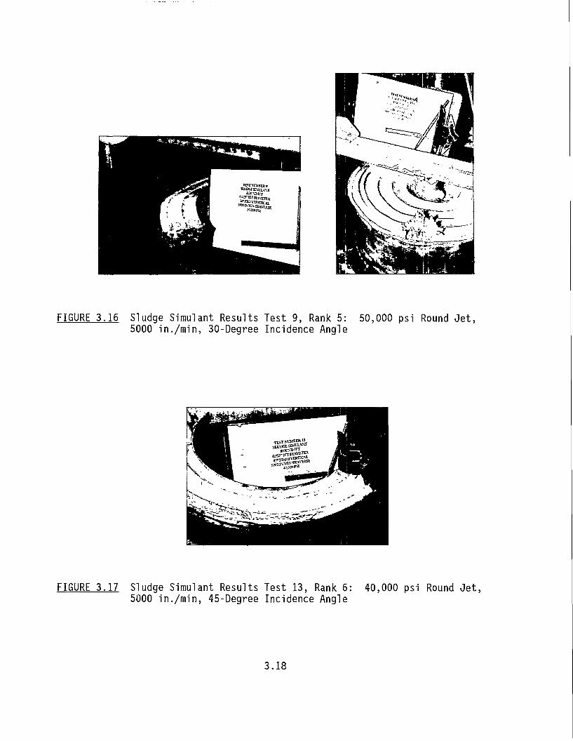
FIGURE 3.16 Sludge Simulant Results Test 9, Rank 5: 50,000 psi Round Jet, 5000 in./min, 30-Degree Incidence Angle
FIGURE 3.17 Sludge Simulant Results Test 13, Rank 6: 5000 in./min, 45-Degree Incidence Angle
40,000 psi Round Jet,
3.18
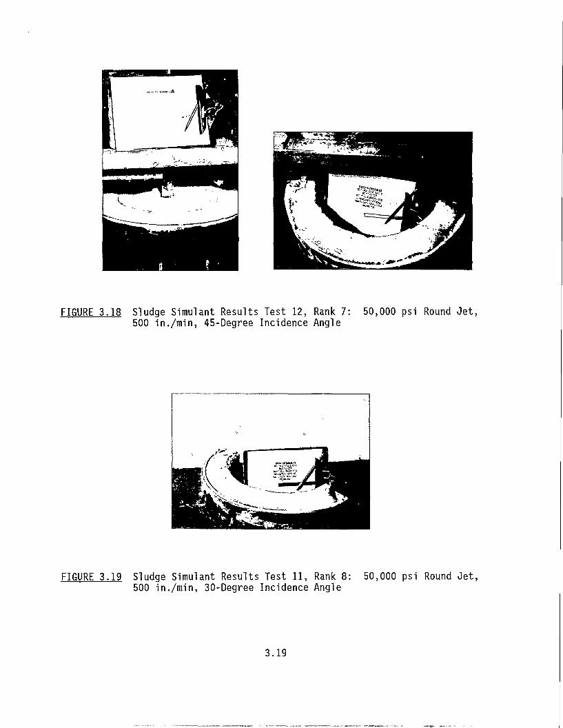
FIGURE 3.18 Sludge Simulant Results Test 12, Rank 7: 500 in./min, 45-Degree Incidence Angle
50,000 psi Round Jet,
FIGURE 3.19 Sludge Simulant Results Test 11, Rank 8: 500 in./min, 30-Degree Incidence Angle
50,000 psi Round Jet,
3.19
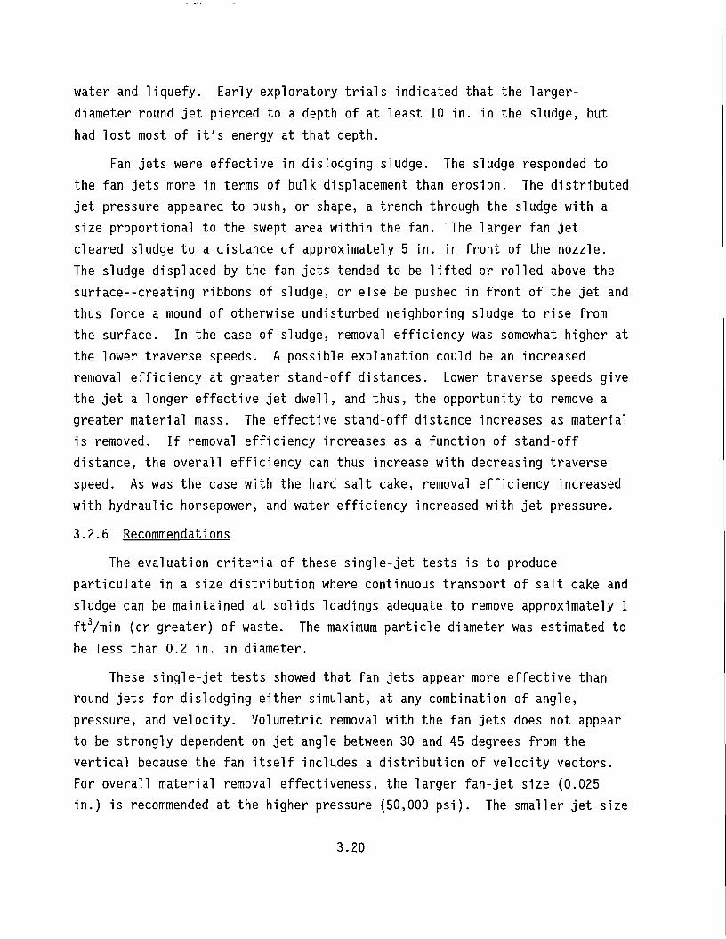
water and liquefy. Early exploratory trials indicated that the larger-diameter round jet pierced to a depth of at least 10 in. in the sludge, but had lost most of it's energy at that depth.
Fan jets were effective in dislodging sludge. The sludge responded to the fan jets more in terms of bulk displacement than erosion. The distributed jet pressure appeared to push, or shape, a trench through the sludge with a size proportional to the swept area within the fan. The larger fan jet cleared sludge to a distance of approximately 5 in. in front of the nozzle. The sludge displaced by the fan jets tended to be lifted or rolled above the surface—creating ribbons of sludge, or else be pushed in front of the jet and thus force a mound of otherwise undisturbed neighboring sludge to rise from the surface. In the case of sludge, removal efficiency was somewhat higher at the lower traverse speeds. A possible explanation could be an increased removal efficiency at greater stand-off distances. Lower traverse speeds give the jet a longer effective jet dwell, and thus, the opportunity to remove a greater material mass. The effective stand-off distance increases as material is removed. If removal efficiency increases as a function of stand-off distance, the overall efficiency can thus increase with decreasing traverse speed. As was the case with the hard salt cake, removal efficiency increased with hydraulic horsepower, and water efficiency increased with jet pressure.
3.2.6 Recommendations
The evaluation criteria of these single-jet tests is to produce particulate in a size distribution where continuous transport of salt cake and sludge can be maintained at solids loadings adequate to remove approximately 1 ft3/min (or greater) of waste. The maximum particle diameter was estimated to be less than 0.2 in. in diameter.
These single-jet tests showed that fan jets appear more effective than round jets for dislodging either simulant, at any combination of angle, pressure, and velocity. Volumetric removal with the fan jets does not appear to be strongly dependent on jet angle between 30 and 45 degrees from the vertical because the fan itself includes a distribution of velocity vectors. For overall material removal effectiveness, the larger fan-jet size (0.025 in.) is recommended at the higher pressure (50,000 psi). The smaller jet size
3.20
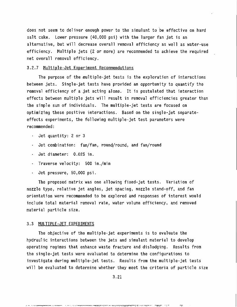
does not seem to deliver enough power to the simulant to be effective on hard salt cake. Lower pressure (40,000 psi) with the larger fan jet is an alternative, but will decrease overall removal efficiency as well as water-use efficiency. Multiple jets (2 or more) are recommended to achieve the required net overall removal efficiency. 3.2.7 Multiple-Jet Experiment Recommendations
The purpose of the multiple-jet tests is the exploration of interactions between jets. Single-jet tests have provided an opportunity to quantify the removal efficiency of a jet acting alone. It is postulated that interaction effects between multiple jets will result in removal efficiencies greater than the simple sum of individuals. The multiple-jet tests are focused on optimizing these positive interactions. Based on the single-jet separate-effects experiments, the following multiple-jet test parameters were recommended:
• Jet quantity: 2 or 3 • Jet combination: fan/fan, round/round, and fan/round • Jet diameter: 0.025 in. • Traverse velocity: 500 in./min • Jet pressure, 50,000 psi.
The proposed matrix was one allowing fixed-jet tests. Variation of nozzle type, relative jet angles, jet spacing, nozzle stand-off, and fan orientation were recommended to be explored and responses of interest would include total material removal rate, water volume efficiency, and removed material particle size.
3.3 MULTIPLE-JET EXPERIMENTS The objective of the multiple-jet experiments is to evaluate the
hydraulic interactions between the jets and simulant material to develop operating regimes that enhance waste fracture and dislodging. Results from the single-jet tests were evaluated to determine the configurations to investigate during multiple-jet tests. Results from the multiple-jet tests will be evaluated to determine whether they meet the criteria of particle size
3.21
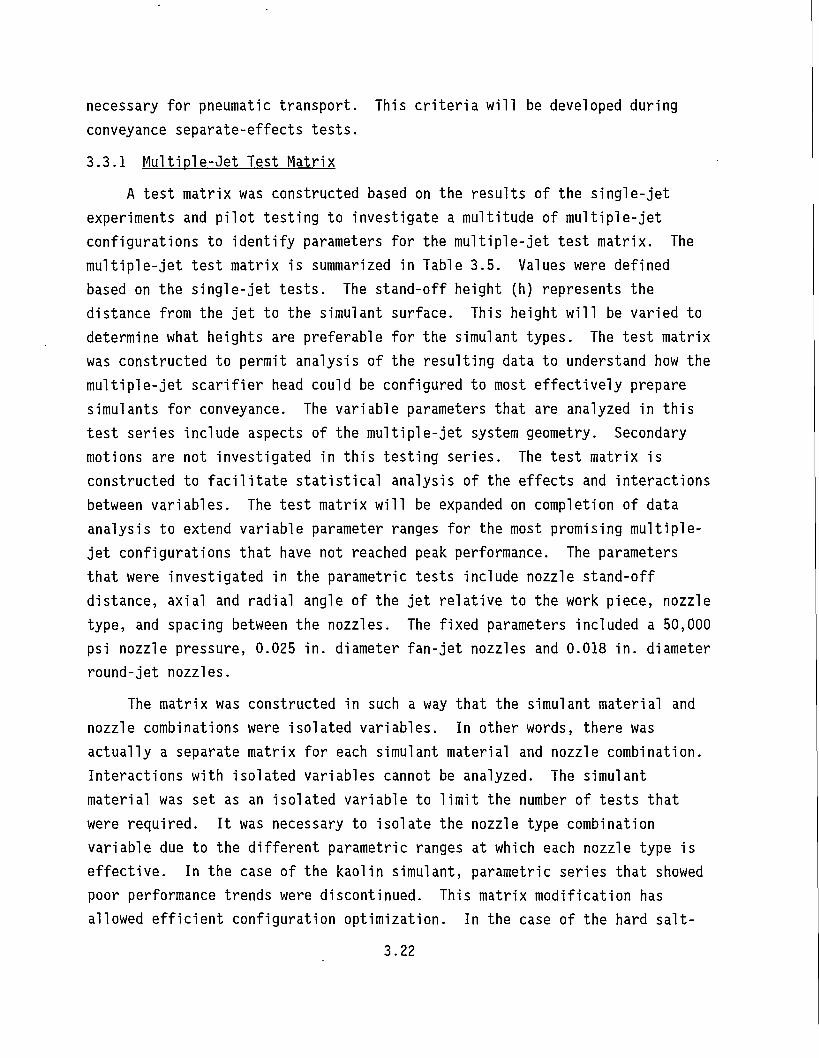
necessary for pneumatic transport. This criteria will be developed during conveyance separate-effects tests. 3.3.1 Multiple-Jet Test Matrix
A test matrix was constructed based on the results of the single-jet experiments and pilot testing to investigate a multitude of multiple-jet configurations to identify parameters for the multiple-jet test matrix. The multiple-jet test matrix is summarized in Table 3.5. Values were defined based on the single-jet tests. The stand-off height (h) represents the distance from the jet to the simulant surface. This height will be varied to determine what heights are preferable for the simulant types. The test matrix was constructed to permit analysis of the resulting data to understand how the multiple-jet scarifier head could be configured to most effectively prepare simulants for conveyance. The variable parameters that are analyzed in this test series include aspects of the multiple-jet system geometry. Secondary motions are not investigated in this testing series. The test matrix is constructed to facilitate statistical analysis of the effects and interactions between variables. The test matrix will be expanded on completion of data analysis to extend variable parameter ranges for the most promising multiple-jet configurations that have not reached peak performance. The parameters that were investigated in the parametric tests include nozzle stand-off distance, axial and radial angle of the jet relative to the work piece, nozzle type, and spacing between the nozzles. The fixed parameters included a 50,000 psi nozzle pressure, 0.025 in. diameter fan-jet nozzles and 0.018 in. diameter round-jet nozzles.
The matrix was constructed in such a way that the simulant material and nozzle combinations were isolated variables. In other words, there was actually a separate matrix for each simulant material and nozzle combination. Interactions with isolated variables cannot be analyzed. The simulant material was set as an isolated variable to limit the number of tests that were required. It was necessary to isolate the nozzle type combination variable due to the different parametric ranges at which each nozzle type is effective. In the case of the kaolin simulant, parametric series that showed poor performance trends were discontinued. This matrix modification has allowed efficient configuration optimization. In the case of the hard salt-
3.22
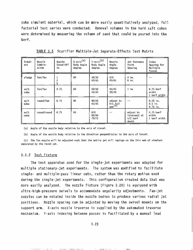
cake simulant material, which can be more easily quantitatively analyzed, full factorial test series were conducted. Removal volumes in the hard salt cakes were determined by measuring the volume of sand that could be poured into the kerf.
TABLE 3.5 Scarifier Multiple-Jet Separate-Effects Test Matrix
Simulant
Nozzle Combi n-ation
Nozzle Stand-Off in.
X-axis ( a )
Body Angle degree
Y-axis ( b )
Body Angle degree
Nozzle Angle degree
Jet Entrance Point Spacing
Index Spacing for Multiple Passes
sludge fan/fan 1 3 6
90 30/30 45/45
0/0 45/45
4 in. 6 in.
—
salt cake
fan/fan 0.75 90 60/60 45/45
45/45 30/30
1 in. 0.75 kerf width 1 kerf width
salt cake
round/fan 0.75 90 90/45 45/45
adjust to hit,full web(c>
— 0.25 in. 0.5 in. 0.75 in.
salt cake
round/round 0.75 90 0/0 60/60 75/75
adjust to intersect at 1/2 kerf depth
0.75 kerf width 1 kerf width
(a) Angle of the nozzle body relative to the axis of travel.
(b) Angle of the nozzle body relative to the direction perpendicular to the axis of travel.
(c) The fan nozzle will be adjusted such that the entire jet will impinge on the thin web of simulant separated by the round jet.
3.3.2 Test Fixture The test apparatus used for the single-jet experiments was adapted for
multiple stationary-jet experiments. The system was modified to facilitate single- and multiple-pass linear cuts, rather than the rotary motion used during the single-jet experiments. This configuration created data that was more easily analyzed. The nozzle fixture (Figure 3.20) is equipped with ultra-high-pressure swivels to accommodate angularity adjustments. Fan-jet nozzles can be rotated inside the nozzle bodies to produce various radial jet positions. Nozzle spacing can be adjusted by moving the swivel mounts on the support arm. X-axis nozzle traverse is supplied by the automated traverse mechanism. Y-axis indexing between passes is facilitated by a manual lead
3.23
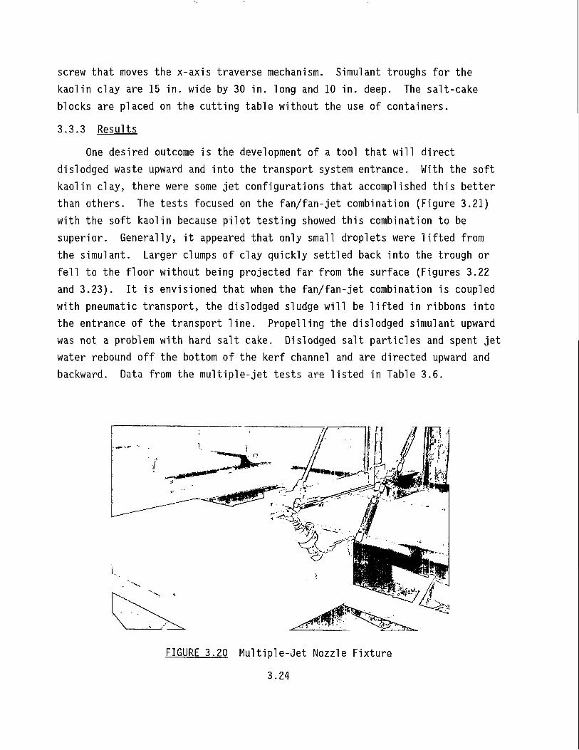
screw that moves the x-axis traverse mechanism. Simulant troughs for the kaolin clay are 15 in. wide by 30 in. long and 10 in. deep. The salt-cake blocks are placed on the cutting table without the use of containers. 3.3.3 Results
One desired outcome is the development of a tool that will direct dislodged waste upward and into the transport system entrance. With the soft kaolin clay, there were some jet configurations that accomplished this better than others. The tests focused on the fan/fan-jet combination (Figure 3.21) with the soft kaolin because pilot testing showed this combination to be superior. Generally, it appeared that only small droplets were lifted from the simulant. Larger clumps of clay quickly settled back into the trough or fell to the floor without being projected far from the surface (Figures 3.22 and 3.23). It is envisioned that when the fan/fan-jet combination is coupled with pneumatic transport, the dislodged sludge will be lifted in ribbons into the entrance of the transport line. Propelling the dislodged simulant upward was not a problem with hard salt cake. Dislodged salt particles and spent jet water rebound off the bottom of the kerf channel and are directed upward and backward. Data from the multiple-jet tests are listed in Table 3.6.
FIGURE 3.20 Multiple-Jet Nozzle Fixture 3.24
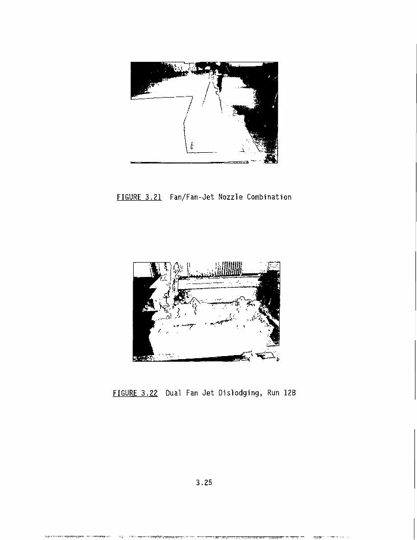
FIGURE 3.21 Fan/Fan-Jet Nozzle Combination
FIGURE 3.22 Dual Fan Jet Dislodging, Run 12B
3.25
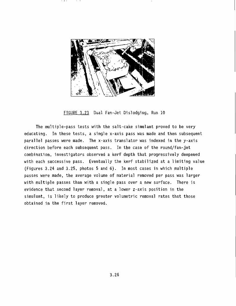
FIGURE 3.23 Dual Fan-Jet Dislodging, Run 10
The multiple-pass tests with the salt-cake simulant proved to be very educating. In these tests, a single x-axis pass was made and then subsequent parallel passes were made. The x-axis translator was indexed in the y-axis direction before each subsequent pass. In the case of the round/fan-jet combination, investigators observed a kerf depth that progressively deepened with each successive pass. Eventually the kerf stabilized at a limiting value (Figures 3.24 and 3.25, photos 5 and 6). In most cases in which multiple passes were made, the average volume of material removed per pass was larger with multiple passes than with a single pass over a new surface. There is evidence that second layer removal, at a lower z-axis position in the simulant, is likely to produce greater volumetric removal rates that those obtained in the first layer removed.
3.26
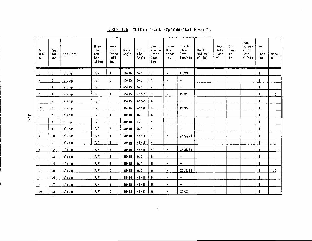
TABLE 3.6 Multiple-Jet Experimental Results
Run Number
Test Number
Simulant
Nozz le Comb in at ion
Nozz le Stand - o f f i n .
Body Angle
Nozz le Angle
Entrance Point Spacing
Index Distance in.
Nozzle Flow Rate 1bm/mi n
Kerf Vol ume ml (a)
Ave Vol / Pass ml
Cut Length i n .
Ave. Volume t r i c Rate ml/mi n
No. of Pass -es
Note s
1 1 sludge F/F 1 45/45 0/0 4 _ 24/22
- 2 sludge F/F 3 45/45 0/0 4 _ _
- 3 sludge F/F 6 45/45 0/0 4 _ _
2 4 sludge F/F 1 45/45 45/45 4 _ 24/23 (b) _ 5 sludge F/F 3 45/45 45/45 4 - -
12 6 sludge F/F 6 45/45 45/45 4 _ 24/23
- 7 sludge F/F 1 30/30 0/0 4 _ _
„ 8 sludge F/F 3 30/30 0/0 4 _ _
, 9 sludge F/F 6 30/30 0/0 4 _ -
3 10 sludge F/F 1 30/30 45/45 4 . 24/22.5
.. 11 sludge F/F 3 30/30 45/45 4 _ _
5 12 sludge F/F 6 30/30 45/45 4 _ 24.5/23
_ 13 sludge F/F 1 45/45 0/0 6 - -
_ 14 sludge F/F 3 45/45 0/0 6 _ _ 1 •
11 15 sludge F/F 6 45/45 0/0 6 _ 23.5/24 (c)
„ 16 sludge F/F 1 45/45 45/45 6 _ _
- 17 sludge F/F 3 45/45 45/45 6 - -
10 18 sludge F/F 6 45/45 45/45 6 - 25/23
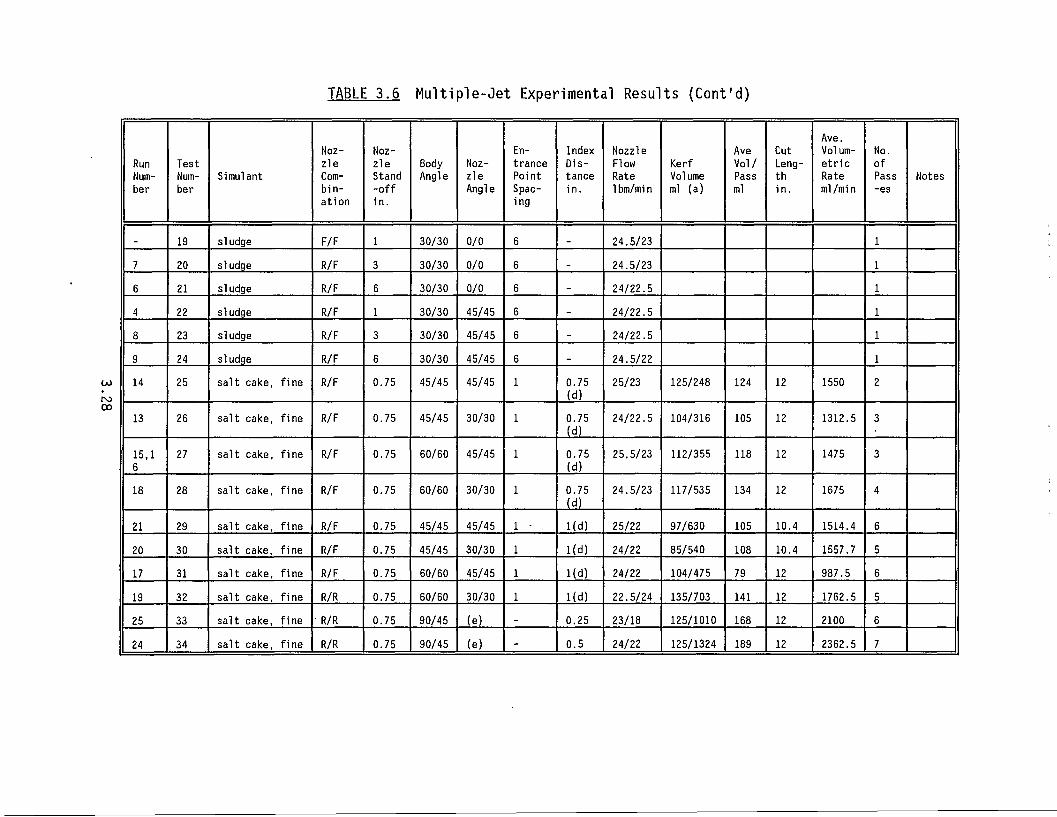
TABLE 3.6 Multiple-Jet Experimental Results (Cont'd)
Run Number
Test Number
Simulant
Nozzle Combination
Nozzle Stand -off in.
Body Angle
Nozzle Angle
Entrance Point Spacing
Index Distance in.
Nozzle Flow Rate 1bm/mi n
Kerf Volume ml (a)
Ave Vol/ Pass ml
Cut Length in.
Ave. Volumetric Rate ml/mi n
No. of Pass -es
Notes
_ 19 sludge F/F 1 30/30 0/0 6 _ 24.5/23
7 20 sludge R/F 3 30/30 0/0 6 _ 24.5/23
6 21 sludge R/F 6 30/30 0/0 6 _ 24/22.5
4 22 sludge R/F 1 30/30 45/45 6 _ 24/22.5
8 23 sludge R/F 3 30/30 45/45 6 _ 24/22.5
9 24 sludge R/F 6 30/30 45/45 6 _ 24.5/22
14 25 salt cake, fine R/F 0.75 45/45 45/45 0.75 (d)
25/23 125/248 124 12 1550 2
13 26 salt cake, fine R/F 0.75 45/45 30/30 0.75 (d)
24/22.5 104/316 105 12 1312.5 3
15,1 6
27 salt cake, fine R/F 0.75 60/60 45/45 0.75 (d)
25.5/23 112/355 118 12 1475 3
18 28 salt cake, fine R/F 0.75 60/60 30/30 0.75 (d)
24.5/23 117/535 134 12 1675 4
21 29 salt cake, fine R/F 0.75 45/45 45/45 Kd) 25/22 97/630 105 10.4 1514.4 6 20 30 salt cake, fine R/F 0.75 45/45 30/30 1(d) 24/22 85/540 108 10.4 1557.7 5 17 31 salt cake, fine R/F 0.75 60/60 45/45 Kd) 24/22 104/475 79 12 987.5 6 19 32 salt cake, fine R/R 0.75 60/60 30/30 Kd) 22.5/24 135/703 141 12 1762.5 5 25 33 salt cake, fine • R/R 0.75 90/45 (e) _ 0.25 23/18 125/1010 168 12 2100 6 24 34 salt cake, fine R/R 0.75 90/45 (e) - 0.5 24/22 125/1324 189 12 2362.5 7
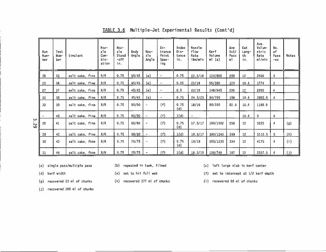
TABLE 3.6 Multiple-Jet Experimental Results (Cont'd)
Run Number
Test Number
Simulant
Nozzle Combination
Nozzle Stand -off in.
Body Angle
Nozzle Angle
Entrance Point Spacing
Index Distance in.
Nozzle Flow Rate 1bm/mi n
Kerf Volume ml (a)
Ave Vol/ Pass ml
Cut Length in.
Ave. Volum-etric Rate ml/min
No. of Pass -es
Notes
26 35 salt cake, fine R/R 0.75 90/45 (e) _ 0.75 23.5/18 124/800 200 12 2500 4 23 36 salt cake, fine R/R 0.75 45/45 (e) « 0.25 23/18 95/369 123 10.4 1774 3 27 37 salt cake, fine R/R 0.75 45/45 (e) _ 0.5 23/18 148/945 236 12 2950 4 22 38 salt cake, fine R/R 0.75 45/45 (e) _ 0.75 24.5/23 94/790 198 10.4 2855.8 4 32 39 salt cake, fine R/R 0.75 90/90 - (f) 0.75
(d) 18/16 80/330 82.5 10.4 1189.9
_ 40 salt cake, fine R/R 9.75 90/90 _ (f) Kd) „ 10.4 0 4 29 41 salt cake, fine R/R 0.75 60/60 - (f) 0.75
(d) 17.5/17 190/1032 258 12 3225 4 (g)
28 42 salt cake, fine R/R 0.75 60/60 _ (f) Kd) 18.5/17 190/1243 249 12 3112.5 5 (h) 30 43 salt cake, fine R/R 0.75 75/75 - (f) 0.75
(d) 18/18 205/1335 334 12 4175 4 (i)
31 44 salt cake, fine R/R 0.75 75/75 - (f) Kd) 18.5/19 138/749 187 12 2337.5 4 ( j )
(a) single pass/multiple pass (b) repeated in tank, filmed (c) left large slab in kerf center
(d) kerf width (e) set to hit full web (f) set to intercept at 1/2 kerf depth
(g) recovered 23 ml of chunks (h) recovered 277 ml of chunks (i) recovered 60 ml of chunks
(j) recovered 285 ml of chunks
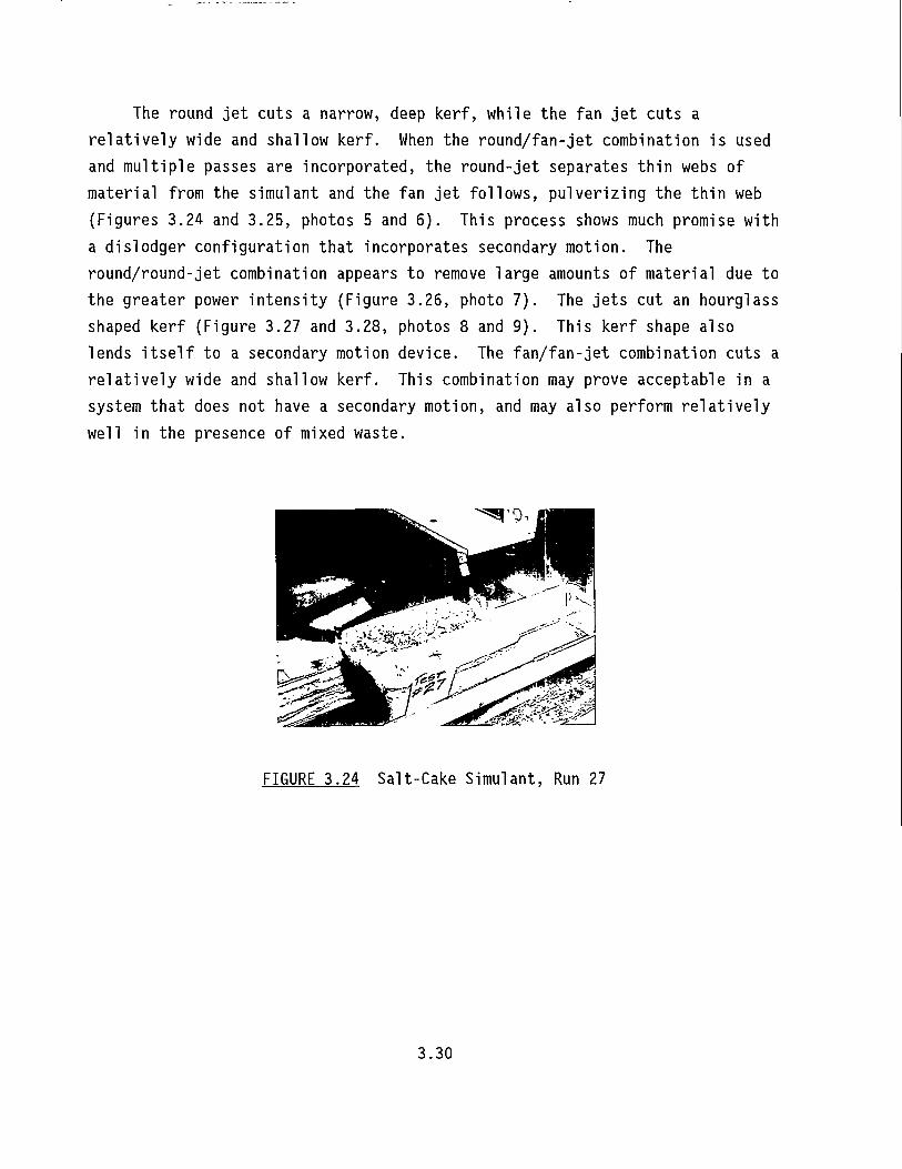
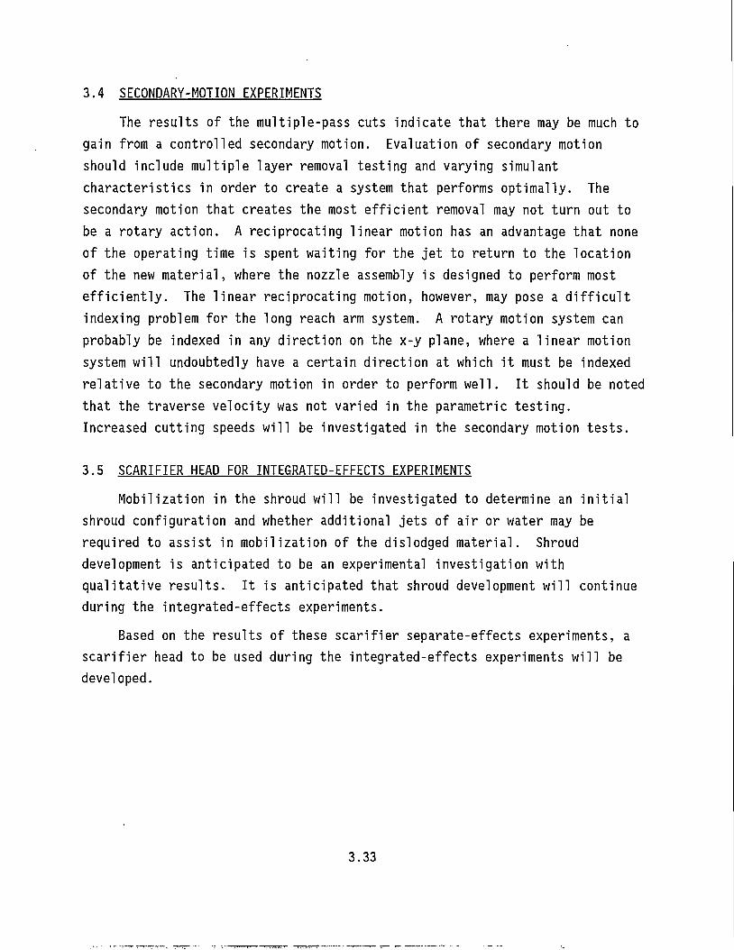
The round jet cuts a narrow, deep kerf, while the fan jet cuts a relatively wide and shallow kerf. When the round/fan-jet combination is used and multiple passes are incorporated, the round-jet separates thin webs of material from the simulant and the fan jet follows, pulverizing the thin web (Figures 3.24 and 3.25, photos 5 and 6). This process shows much promise with a dislodger configuration that incorporates secondary motion. The round/round-jet combination appears to remove large amounts of material due to the greater power intensity (Figure 3.26, photo 7). The jets cut an hourglass shaped kerf (Figure 3.27 and 3.28, photos 8 and 9). This kerf shape also lends itself to a secondary motion device. The fan/fan-jet combination cuts a relatively wide and shallow kerf. This combination may prove acceptable in a system that does not have a secondary motion, and may also perform relatively well in the presence of mixed waste.
FIGURE 3.24 Salt-Cake Simulant, Run 27
3.30
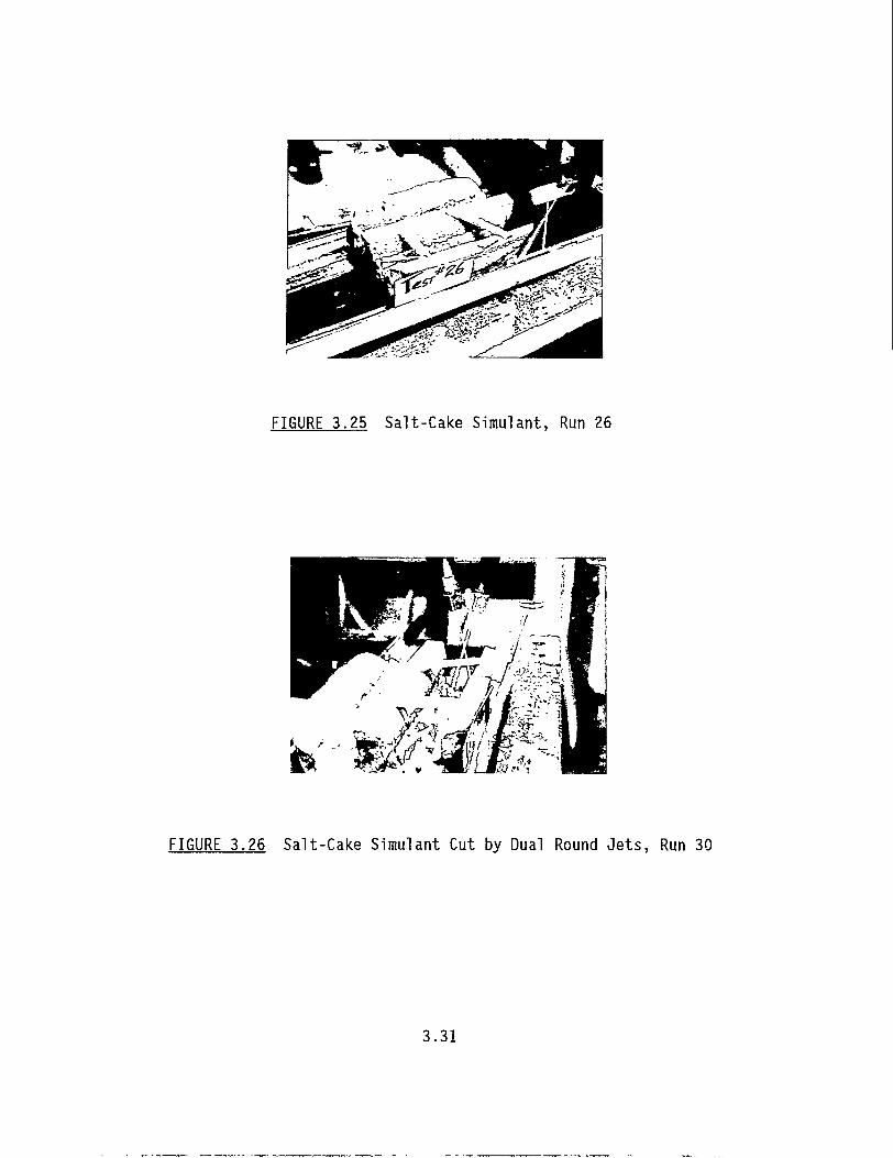
FIGURE 3.25 Salt-Cake Simulant, Run 26
te"' 'mw*-wiM&. "•
FIGURE 3.26 Salt-Cake Simulant Cut by Dual Round Jets, Run 30
3.31
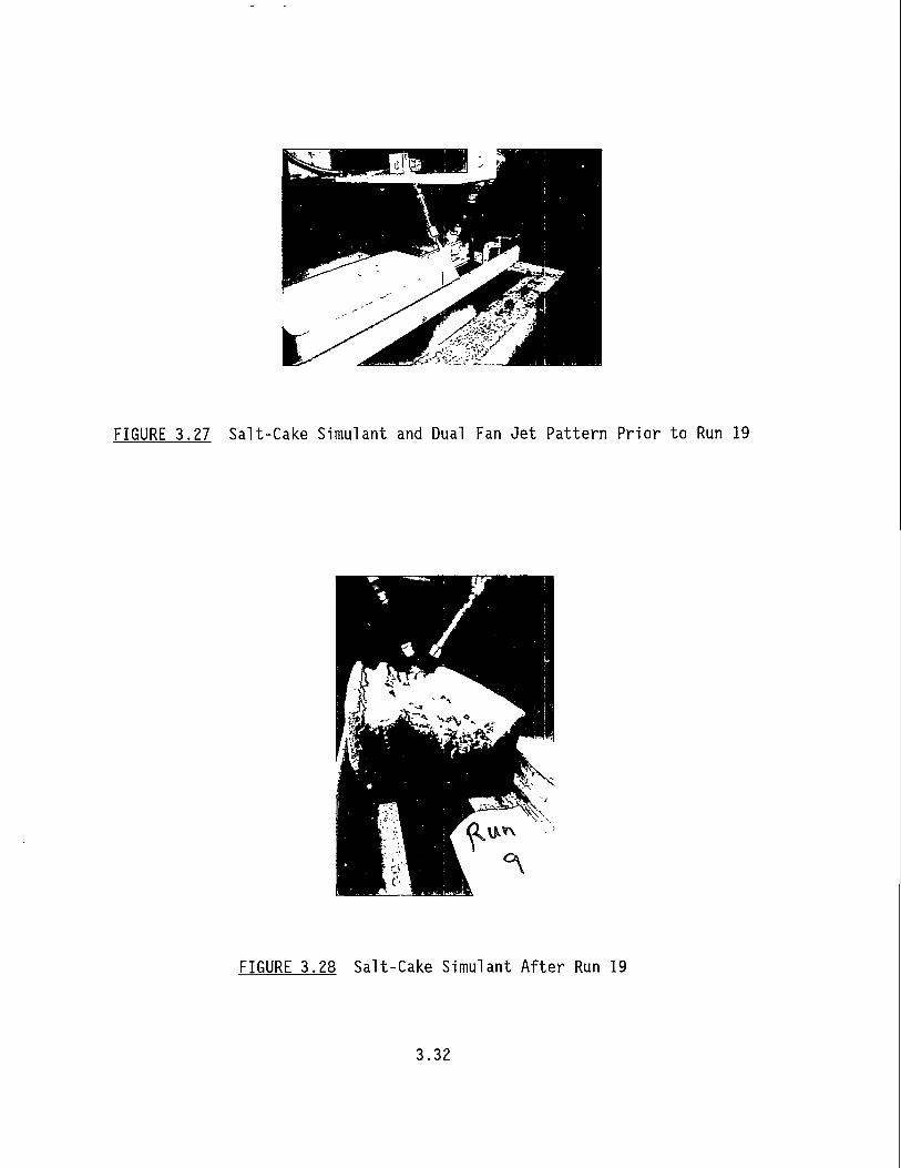
FIGURE 3.27 Salt-Cake Simulant and Dual Fan Jet Pattern Pr ior to Run 19
FIGURE 3.28 Salt-Cake Simulant Af ter Run 19
3.32
3.4 SECONDARY-MOTION EXPERIMENTS The results of the multiple-pass cuts indicate that there may be much to
gain from a controlled secondary motion. Evaluation of secondary motion should include multiple layer removal testing and varying simulant characteristics in order to create a system that performs optimally. The secondary motion that creates the most efficient removal may not turn out to be a rotary action. A reciprocating linear motion has an advantage that none of the operating time is spent waiting for the jet to return to the location of the new material, where the nozzle assembly is designed to perform most efficiently. The linear reciprocating motion, however, may pose a difficult indexing problem for the long reach arm system. A rotary motion system can probably be indexed in any direction on the x-y plane, where a linear motion system will undoubtedly have a certain direction at which it must be indexed relative to the secondary motion in order to perform well. It should be noted that the traverse velocity was not varied in the parametric testing. Increased cutting speeds will be investigated in the secondary motion tests.
3.5 SCARIFIER HEAD FOR INTEGRATED-EFFECTS EXPERIMENTS Mobilization in the shroud will be investigated to determine an initial
shroud configuration and whether additional jets of air or water may be required to assist in mobilization of the dislodged material. Shroud development is anticipated to be an experimental investigation with qualitative results. It is anticipated that shroud development will continue during the integrated-effects experiments.
Based on the results of these scarifier separate-effects experiments, a scarifier head to be used during the integrated-effects experiments will be developed.
3.33
4.0 PNEUMATIC CONVEYANCE DEVELOPMENT
The objective of the pneumatic conveyance development is to develop correlations describing the retrieval of the "three-phase" single-shell tank waste: solids (either salt cake or sludge), liquid (viscous interstitial fluid in the tank, scarifier cutting liquid, and water used to lubricate the inside of the conveyance line), and air (the carrier medium).
In FY93 three activities supported this development: developing a scaling methodology for pneumatic conveyance, preparing the test plan for the pneumatic conveyance separate effects experiments, and designing and constructing the test fixture for the pneumatic conveyance separate-and integrated-effects experiments. In FY94 the pneumatic conveyance separate-effects experiments will be conducted, followed by the combined scarifier/conveyance integrated-effects experiments.
4.1 THEORY AND SCALING To allow the effect of varying transport line diameter to be
investigated, a dimensional analysis was conducted to quantify the effects of increasing retrieval rate and pipe diameter. The dimensional variables associated with pneumatic transport of the "three-phase" mixture (waste moistened by the scarifier cutting fluid and the conveyance line lubricant transported in air) can be grouped by gas-phase parameters, particle-phase parameters, and other parameters as listed in Table 4.1.
The gas-phase parameters include gas-phase velocity, density and viscosity. The particle-phase parameters include particle diameter, particle-phase density, particle mas.s flow rate, and yield stress for particulate material. The particle mass flow rate (M ) was chosen instead of the particle-phase velocity, T represents the yield stress for the particulate. The adhesive/cohesive nature (stickiness) of the particles could possibly also be represented as a yield stress so this parameter represents both a threshold yield stress for the particulate material as well as a "stickiness" parameter.
4.1
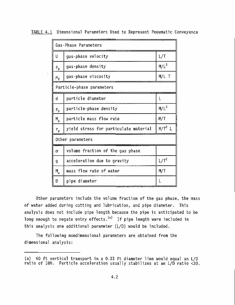
TABLE 4.1 Dimensional Parameters Used to Represent Pneumatic Conveyance
Gas-Phase Parameters
U gas-phase ve loc i ty L/T
Pg gas-phase density M/L3
h gas-phase v iscos i ty M/L T
Particle-phase parameters
d pa r t i c l e diameter L
PP part ic le-phase density M/L3
M P pa r t i c l e mass f low rate M/T
T P y i e l d stress for par t i cu la te material M/T2 L
Other parameters
a volume f rac t ion of the gas phase
g acceleration due to grav i ty L/T2
M w mass flow rate of water M/T
D pipe diameter L
Other parameters include the volume fraction of the gas phase, the mass of water added during cutting and lubrication, and pipe diameter. This analysis does not include pipe length because the pipe is anticipated to be long enough to negate entry effects. ( a ) If pipe length were included in this analysis one additional parameter (L/D) would be included.
The following nondimensional parameters are obtained from the dimensional analysis:
(a) 60 ft vertical transport in a 0.33 ft diameter line would equal an L/D ratio of 180. Particle acceleration usually stabilizes at an L/D ratio <30.
4.2
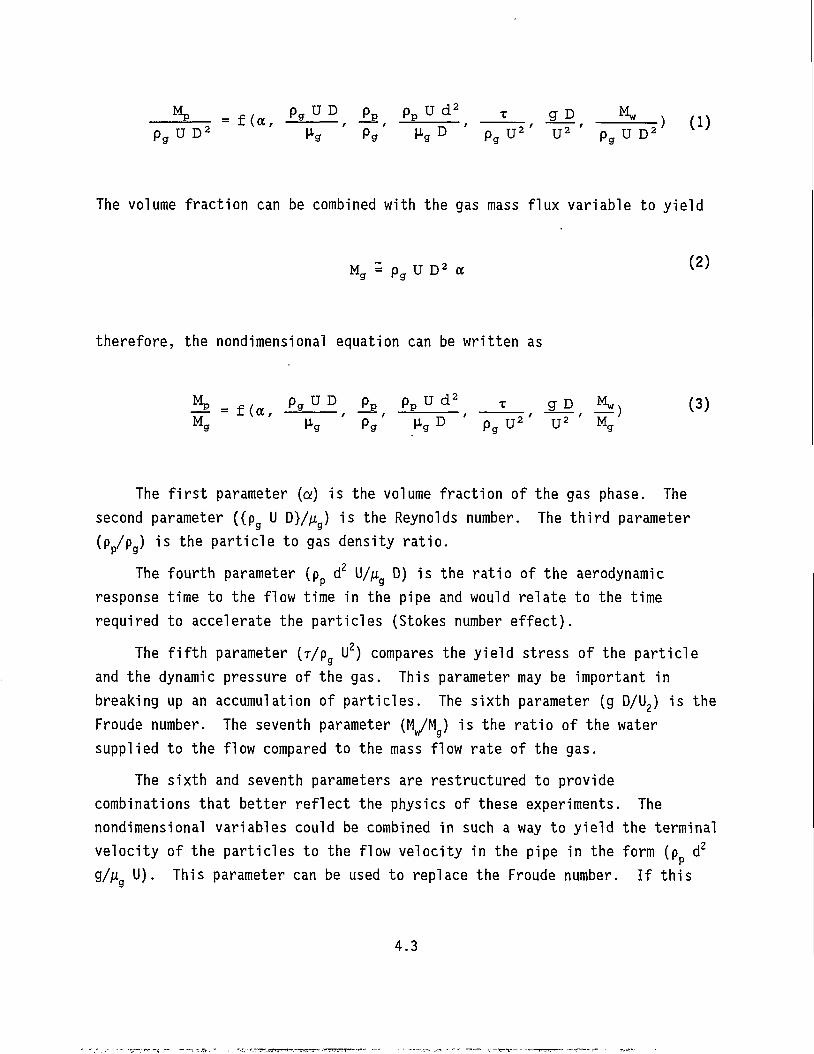
_ i k _ = f ( a , £*_^, i* , Jfe™!, _ E _ , *J>, _ J t _ , ( 1 )
P g U D 2 H f f Pg H g D p g u 2 U 2 p g U D 2
The volume fraction can be combined with the gas mass flux variable to yield
M g = p g U D 2 a (2'
therefore, the nondimensional equation can be written as
^ E = f ( a p g U D i s P p u d 2 t g D K) (3) Mg ' Hg ' P g ' H g D ' P g U
2 ' U 2 ' M g
The first parameter (a) is the volume fraction of the gas phase. The second parameter ({p U D}/u ) is the Reynolds number. The third parameter (p /p ) is the particle to gas density ratio.
The fourth parameter (p d 2 U/ju D) is the ratio of the aerodynamic response time to the flow time in the pipe and would relate to the time required to accelerate the particles (Stokes number effect).
The fifth parameter (r/p U 2) compares the yield stress of the particle and the dynamic pressure of the gas. This parameter may be important in breaking up an accumulation of particles. The sixth parameter (g D/U2) is the Froude number. The seventh parameter (MyM ) is the ratio of the water supplied to the flow compared to the mass flow rate of the gas.
The sixth and seventh parameters are restructured to provide combinations that better reflect the physics of these experiments. The nondimensional variables could be combined in such a way to yield the terminal velocity of the particles to the flow velocity in the pipe in the form (p d 2
g/jiig U). This parameter can be used to replace the Froude number. If this
4.3
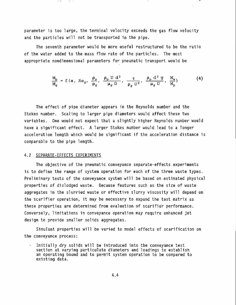
parameter is too large, the terminal velocity exceeds the gas flow velocity and the particles will not be transported in the pipe.
The seventh parameter would be more useful restructured to be the ratio of the water added to the mass flow rate of the particles. The most appropriate nondimensional parameters for pneumatic transport would be
^ - f (a, Re g, £ E , P p p d a , _ * _ , P * d 2 g , £ , W M g
g P g H g D p g U 2 ' H g U Mp
The effect of pipe diameter appears in the Reynolds number and the Stokes number. Scaling to larger pipe diameters would affect these two variables. One would not expect that a slightly higher Reynolds number would have a significant effect. A larger Stokes number would lead to a longer acceleration length which would be significant if the acceleration distance is comparable to the pipe length.
4.2 SEPARATE-EFFECTS EXPERIMENTS The objective of the pneumatic conveyance separate-effects experiments
is to define the range of system operation for each of the three waste types. Preliminary tests of the conveyance system will be based on estimated physical properties of dislodged waste. Because features such as the size of waste aggregates in the slurried waste or effective slurry viscosity will depend on the scarifier operation, it may be necessary to expand the test matrix as these properties are determined from evaluation of scarifier performance. Conversely, limitations in conveyance operation may require enhanced jet design to provide smaller solids aggregates.
Simulant properties will be varied to model effects of scarification on the conveyance process:
Initially dry solids will be introduced into the conveyance test section at varying particulate diameters and loadings to establish an operating bound and to permit system operation to be compared to existing data.
4.4
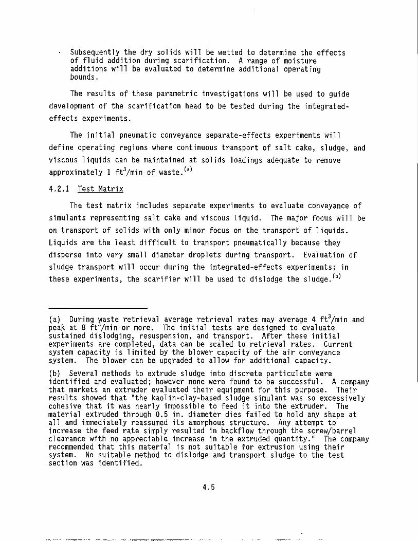
• Subsequently the dry solids will be wetted to determine the effects of fluid addition during scarification. A range of moisture additions will be evaluated to determine additional operating bounds. The results of these parametric investigations will be used to guide
development of the scarification head to be tested during the integrated-effects experiments.
The initial pneumatic conveyance separate-effects experiments will define operating regions where continuous transport of salt cake, sludge, and viscous liquids can be maintained at solids loadings adequate to remove approximately 1 ft3/min of waste. ( a )
4.2.1 Test Matrix The test matrix includes separate experiments to evaluate conveyance of
simulants representing salt cake and viscous liquid. The major focus will be on transport of solids with only minor focus on the transport of liquids. Liquids are the least difficult to transport pneumatically because they disperse into very small diameter droplets during transport. Evaluation of sludge transport will occur during the integrated-effects experiments; in these experiments, the scarifier will be used to dislodge the sludge.(b)
(a) During waste retrieval average retrieval rates may average 4 ft3/min and peak at 8 ft3/min or more. The initial tests are designed to evaluate sustained dislodging, resuspension, and transport. After these initial experiments are completed, data can be scaled to retrieval rates. Current system capacity is limited by the blower capacity of the air conveyance system. The blower can be upgraded to allow for additional capacity. (b) Several methods to extrude sludge into discrete particulate were identified and evaluated; however none were found to be successful. A company that markets an extruder evaluated their equipment for this purpose. Their results showed that "the kaolin-clay-based sludge simulant was so excessively cohesive that it was nearly impossible to feed it into the extruder. The material extruded through 0.5 in. diameter dies failed to hold any shape at all and immediately reassumed its amorphous structure. Any attempt to increase the feed rate simply resulted in backflow through the screw/barrel clearance with no appreciable increase in the extruded quantity." The company recommended that this material is not suitable for extrusion using their system. No suitable method to dislodge and transport sludge to the test section was identified.
4.5
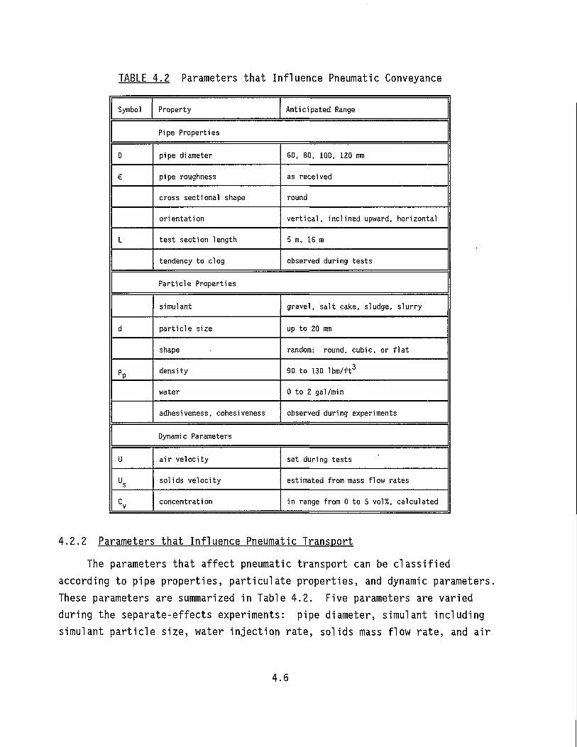
TABLE 4.2 Parameters that Influence Pneumatic Conveyance
Symbol Property Anticipated Range
Pipe Properties
D pipe diameter 60, 80, 100, 120 mm
€ pipe roughness as received
cross sectional shape round
orientation vertical, inclined upward, horizontal
L test section length 5m, 16 m
tendency to clog observed during tests
Particle Properties
simulant gravel, salt cake, sludge, slurry
d particle size up to 20 mm
shape random: round, cubic, or flat
PP density 90 to 130 lbm/ft3
water 0 to 2 gal/min
adhesiveness, cohesiveness observed during experiments
Dynamic Parameters
U air velocity set during tests
Us solids velocity estimated from mass flow rates
C V
concentration in range from 0 to 5 vol%, calculated
4.2.2 Parameters that Influence Pneumatic Transport The parameters that affect pneumatic transport can be classified
according to pipe properties, particulate properties, and dynamic parameters. These parameters are summarized in Table 4.2. Five parameters are varied during the separate-effects experiments: pipe diameter, simulant including simulant particle size, water injection rate, solids mass flow rate, and air
4.6
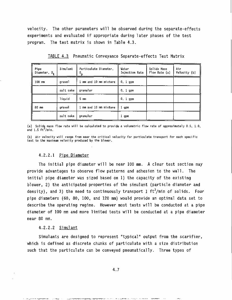
velocity. The other parameters will be observed during the separate-effects experiments and evaluated if appropriate during later phases of the test program. The test matrix is shown in Table 4.3.
TABLE 4.3 Pneumatic Conveyance Separate-effects Test Matrix
Pipe Diameter, D.
Simulant Particulate Diameter, DP
Water Injection Rate
Solids Mass Flow Rate (a)
Air Velocity (b)
100 mm gravel 1 mm and 10 mm mixture 0, 1 gpm
salt cake granular 0, 1 gpm
liquid 5 mm 0, 1 gpm
80 mm gravel 1 mm and 10 mm mixture 1 gpm
salt cake granular 1 gpm
(a) Solids mass flow rate w i l l be calculated to provide a volumetric flow rate of approximately 0.5, 1.0, and 1.5 f t /min.
(b) A i r ve loc i ty w i l l range from near the c r i t i c a l ve loc i ty for par t icu la te transport fo r each spec i f ic tes t to the maximum ve loc i ty produced by the blower.
4.2.2 .1 Pipe Diameter
The initial pipe diameter will be near 100 mm. A clear test section may provide advantages to observe flow patterns and adhesion to the wall. The initial pipe diameter was sized based on 1) the capacity of the existing blov/er, 2) the anticipated properties of the simulant (particle diameter and density), and 3) the need to continuously transport 1 ft3/min of solids. Four pipe diameters (60, 80, 100, and 120 mm) would provide an optimal data set to describe the operating regime. However most tests will be conducted at a pipe diameter of 100 mm and more limited tests will be conducted at a pipe diameter near 80 mm.
4.2.2.2 Simulant Simulants are designed to represent "typical" output from the scarifier,
which is defined as discrete chunks of particulate with a size distribution such that the particulate can be conveyed pneumatically. Three types of
4.7
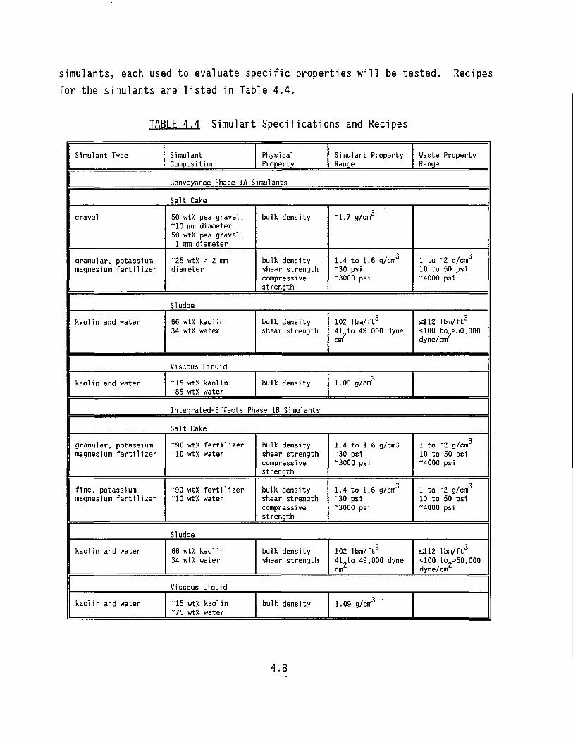
simulants, each used to evaluate specific properties will be tested. Recipes for the simulants are listed in Table 4.4.
TABLE 4.4 Simulant Specifications and Recipes
Simulant Type Simulant Composition
Physical Property
Simulant Property Range
Waste Property Range
Conveyance Phase 1A Simulants
Salt Cake
gravel 50 wt% pea gravel, ~10 mm diameter 50 wt% pea gravel, ~1 mm diameter
bulk density "1.7 g/cm3
granular, potassium magnesium fertilizer
"25 wt% > 2 mm diameter
bulk density shear strength compressive strength
1.4 to 1.6 g/cm3
"30 psi "3000 psi
1 to "2 g/cm3
10 to 50 psi "4000 psi
Sludge
kaoli n and water 66 wt% kaoli n 34 wt% water
bulk density shear strength
102 1 bin/ft3
41 to 49,000 dyne cm
£112 lbm/ft3
<100 to >50,000 dyne/cm
Viscous Liquid
kaoli n and water ~15 wt% kaolin ~85 wt% water
bulk density 1.09 g/cm3
Integrated-Effects Ph ase IB Simulants
Salt Cake
granular, potassium magnesium fertilizer
~90 wt% fertilizer "10 wt% water
bulk density shear strength compressive strength
1.4 to 1.6 g/cm3 "30 psi "3000 psi
1 to ~2 g/cm3
10 to 50 psi "4000 psi
fine, potassium magnesium fertilizer
~90 wt% fertilizer "10 wt% water
bulk density shear strength compressive strength
1.4 to 1.6 g/cm3
~30 psi "3000 psi
1 to "2 g/cm3
10 to 50 psi "4000 psi
Sludge
kaolin and water 66 wt% kaolin 34 wt% water
bulk density shear strength
102 lbm/ft3
41 to 49,000 dyne cm
£112 lbm/ft3
<100 to >50,000 dyne/cm
Viscous Liquid
kaolin and water "15 wt% kaolin ~75 wt% water
bulk density 1.09 g/cm3
4.8
Gravel with a bimodal size distribution with mean diameters near 1 and 10 mm will be evaluated in a 50 wt% mixture to evaluate transport of particle size, density, and concentration matched to that anticipated in the single-shell tanks after waste is fractured and dislodged using the scarifier. The bimodal particle size distribution will allow the effects of interactions between particles of different sizes to be observed. The smaller diameter particles will be transported more quickly through the system than the larger diameter particles; therefore, interaction effects will be included. The gravel is not expected to degrade during testing and can be used multiple times.
A potassium magnesium fertilizer (K-mag) will be used to model the salt cake. This salt is water soluble and possesses properties similar to the salt-cake waste stored in the tanks. During these experiments the effects of wetting the particulate will be evaluated by introducing water to simulate the scarifier cutting jet. The salt may degrade from contact with water; the wetted particulate may adhere to the pipe wall or agglomerate into larger diameter particulate. The wetted simulant may not be able to be reused during the separate-effects experiments. It is anticipated that after the separate-effects tests, the salt cake can be formed into blocks or slabs to be used during the integrated scarifier conveyance tests.
A kaolin clay slurry will be used to simulate the viscous slurry. The slurry viscosity can be varied based on the composition.
4.2.2.3 Water In.iection Rate The simulants will be tested both dry, with no water addition, and wet
with approximately 1 gpm sprayed onto the surface of the simulant as it enters the entrance region of the pneumatic conveyance line. This water spray will simulate the water input from the scarifier during the cutting process and will supply any additional water required to maintain simulant flow.
4.2.2.4 Solids Mass Flow Rate The solids mass flow rates of the salt-cake simulants will be controlled
to provide three volumetric flow rates ranging from 0.5 to 1.5 ft3/min. The design point for the system is to continuously remove 1 ft3/min of solids. If
4.9
rates of 1.5 ft3/min are sustainable, the rate will be increased to 2 ft3/min for selected tests.
4.2.2.5 Air Velocity
At each pipe diameter, the pressure drop per unit length versus velocity will be characterized with only air flow. This will be followed by tests with particulate loading. The air velocity of the system will range from near the critical transport velocity for each simulant at the desired solids mass flow rate to the maximum velocity obtainable with the system blower under those conditions. Multiple air velocities will be investigated for each solids mass flow rate.
4.3 TEST FIXTURE
A schematic diagram for the pneumatic conveyance test equipment is shown in Figure 4.1. Major components, instrumentation, and data acquisition are described.
4.3.1 Ma.ior Components
The major components include the vertical pneumatic conveyance test section, simulant metering equipment, water injection equipment, solids separation system, and the blower.
4.3.1.1 Test Section
The vertical test section consists of an inlet region and transition section ("3 m), a spool piece that may be used to augment flow instrumentation ("1 m), a vertical test section used to monitor pressure drop ("5 m), and a transition piece (~1 m), for an overall vertical length of "9 m. Two systems ("80 and "100 mm in diameter) will be constructed.
4.3.1.2 Simulant Feed
Feed systems will supply a controlled rate of simulant to the entrance of the pneumatic conveyance system. The solids feed system consists of a volumetric feeder with a maximum solids feed rate of 2 ft3/min. This system will be used to meter the solids (gravel and coarse salt) to the entrance of the pneumatic system.
4.10
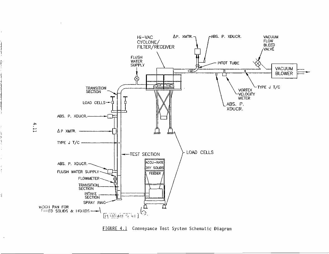
Hi-VAC CYCLONE/ FILTER/RECEIVER
A P. XMTR. ABS. P. XDUCR. VACUUM FLOW BLEED
/VALVE
FLUSH WATER SUPPLY
TRANSITION / ^ SECTION - \ . / f
LOAD CELLS—
WL'ICII PAN FOR f iUFD SOLIDS 8c IIOIIIDS
ABS. P. XDUCR
AP XMTR.
TYPE J T/C
ABS. P. XDUCR.
FLUSH WATER SUPPLY - -~ - iZ£=
FLOWMETER
TRANSITION. SECTION
INTAK SECTION
SPRAY RING
QY^'ii^j"^'-:*' * 1
FIGURE 4.1 Conveyance Test System Schematic Diagram
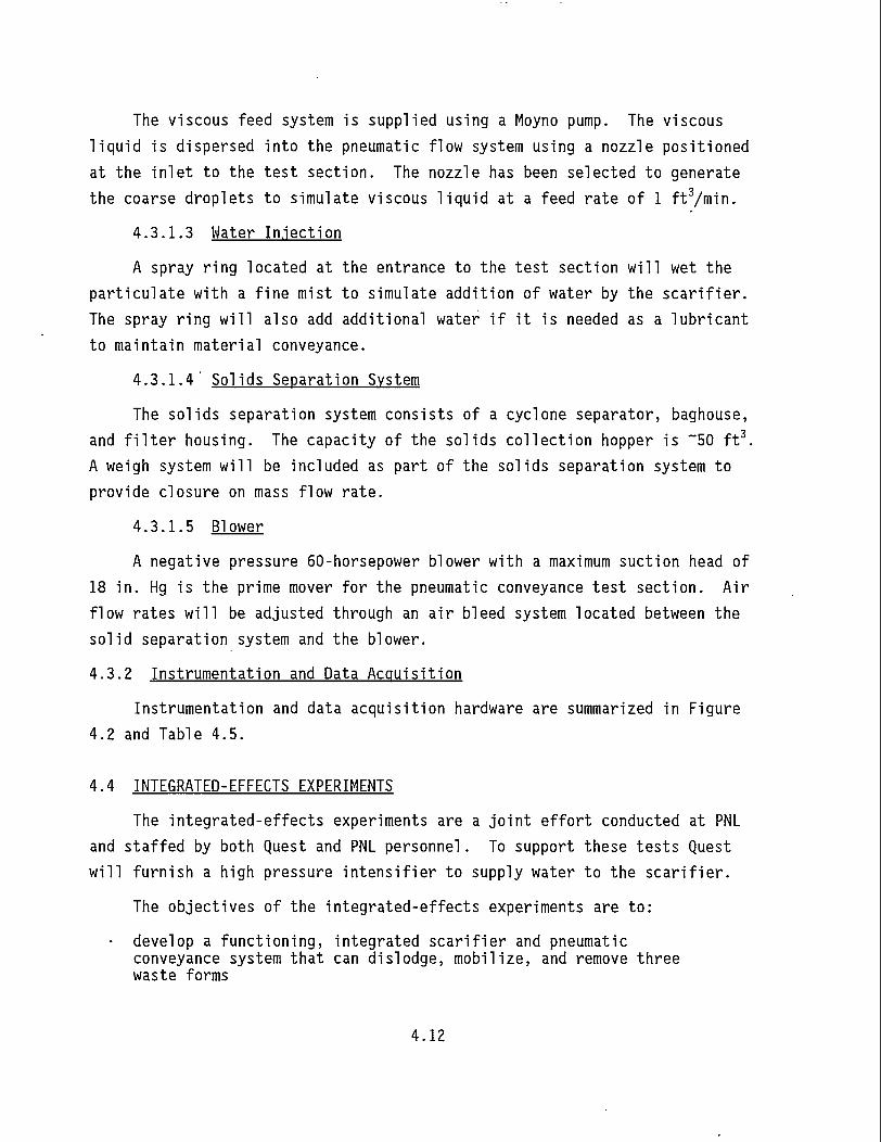
The viscous feed system is supplied using a Moyno pump. The viscous liquid is dispersed into the pneumatic flow system using a nozzle positioned at the inlet to the test section. The nozzle has been selected to generate the coarse droplets to simulate viscous liquid at a feed rate of 1 ft3/min.
4.3.1.3 Hater In.iection
A spray ring located at the entrance to the test section will wet the particulate with a fine mist to simulate addition of water by the scarifier. The spray ring will also add additional water if it is needed as a lubricant to maintain material conveyance.
4.3.1.4' Solids Separation System
The solids separation system consists of a cyclone separator, baghouse, and filter housing. The capacity of the solids collection hopper is ~50 ft3. A weigh system will be included as part of the solids separation system to provide closure on mass flow rate.
4.3.1.5 Blower
A negative pressure 60-horsepower blower with a maximum suction head of 18 in. Hg is the prime mover for the pneumatic conveyance test section. Air flow rates will be adjusted through an air bleed system located between the solid separation system and the blower.
4.3.2 Instrumentation and Data Acquisition
Instrumentation and data acquisition hardware are summarized in Figure 4.2 and Table 4.5.
4.4 INTEGRATED-EFFECTS EXPERIMENTS
The integrated-effects experiments are a joint effort conducted at PNL and staffed by both Quest and PNL personnel. To support these tests Quest will furnish a high pressure intensifier to supply water to the scarifier.
The objectives of the integrated-effects experiments are to:
• develop a functioning, integrated scarifier and pneumatic conveyance system that can dislodge, mobilize, and remove three waste forms
4.12
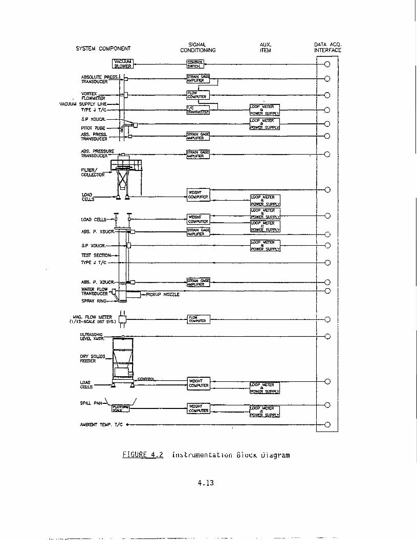
SYSTEM COMPONENT
ABSOLUTE PRESS, TRANSDUCER
SIGNAL CONDITIONING
VORTEX aOWMETER
VACUUM SUPPLY UNE TYPE J T /C
AP XDUCR.
PTOT TUBE A9S. PRESS. TRANSDUCER
ABS. PRESSURE TRANSDUCER
FILTER/ COLLECTOR
LOAD CELLS-
LOAD CELLS
A B S . XDUCR-
AP XDUCR.-
TEST SECTION—
TYPE J T/C —
ABS. P. XDUCR.-
WATER aOW TRANSDUCER
SPRAY Rim-
Q
JSIRAIM CACti PmPUFER V
< 3 - imPUFIER
WAG. FLOW (l/12-SCALE DST
3 Q = METER r~1 3ST SYS.) L_J
PICKUP NOZZLE
COMPUTER
LEVEL xumr
ORY SOUDS_ FEEDER
LOAD CELLS' • £ = 3 ,conreot WEIGHT
COMPUTER
SPtLL PAN A lsc*i> r
WBGHT COMPUTER
AMBIENT TEMP. T/C —
AUX. ITEM
LOOP UETCR
POWSLSUPPLJ
LOOP METER" & POWER SUPPLY
LOOP METER
PCTSR SUPPLY!
DATA ACQ. INTERFACE
-O
-o
-o -o
—o
-o
-o • o
FIGURE 4.2 instrumentation SIUCK. Diagram
4.13
TABLE 4.5 Instrumentation and Data Acquisition
Measurement Sensor Range Desired Accuracy
Sampling Rate
Location
temperature thermocouple ambient, 50 to 100 F
±0.5 C 1/s ambient temperature outside test section, inside test section, and in vacuum supply line
absolute pressure
pressure . . transducer1 '
0 to 15 psia
±0.5% Sl/s as determin ed
test section inlet, outlet and cyclone outlet
absolute pressure
pressure , . transducer1 '
0 to 15 psia
±0.5% 1/s at cyclone outlet (with three press, sensors can determine pressure drop across the cyclone and the filter housing)
differential pressure
differential pressure ,,. transmitter^ '
0 to 2.5 0 to 15 0 to 50 in. Ho0
±0.5% 1/s across test section
air velocity Pi tot tube with absolute pressure transducer*3' and differential pressure . . transmitter1, '
0 to 15 psia, 0 to 0.5 0 to 2 0 to 10 in. H„0
±0.5% in vacuum supply line
air volumetric flow rate
vortex flow meter/ flow computer w/ temperature and absolute pressure inputs
0 to 100 acfm
±2% 1/s in vacuum supply line
dry solids mass and mass rate in feeder
load cells/weigh computer, measure mass and calc. dm/dt in real time
0 to 5K lbm, 0 to 500 1bm/mi n
±3 to 5%
1/s solids feeder
mass and mass rate on feed conveyor
load cells / weigh computer, measure mass and calc. dm/dt in real time
0 to 250 lbm, 0 to 250 1bm/mi n
±3 to 5%
1/s feed conveyor belt
solids receiver/ filter/ collector mass and mass rate
load cells / weigh computer, measure mass and calc. dm/dt in real time
0 to 10K lbm, 0 to 500 1bm/mi n
±5% 1/s collection hopper
water flow rate flow meter 0 to 2 gpm
±5% 1/s spray ring line
viscous liquid flow rate
flow meter 0 to 10 gpm
±0.1% 1/s viscous liquid supply line
(a) Transducer has low-level voltage output requiring amplification.
(b) Transmitter outputs standard process measurement and control: 4 to 20 mA.
4.14
• define operating system regime required for the three waste forms • develop design correlations that can be used to predict system
performance for the three waste forms. The performance criteria will emphasize maximizing the rate of waste and working fluid removal and minimizing the rate of water addition. Mating the scarifier and pneumatic conveyance system is anticipated to require some iteration to make the shroud function in an optimized manner. Initial tests will be conducted with the scarifier mated to a conveyance system with a 5 m vertical section.
4.15
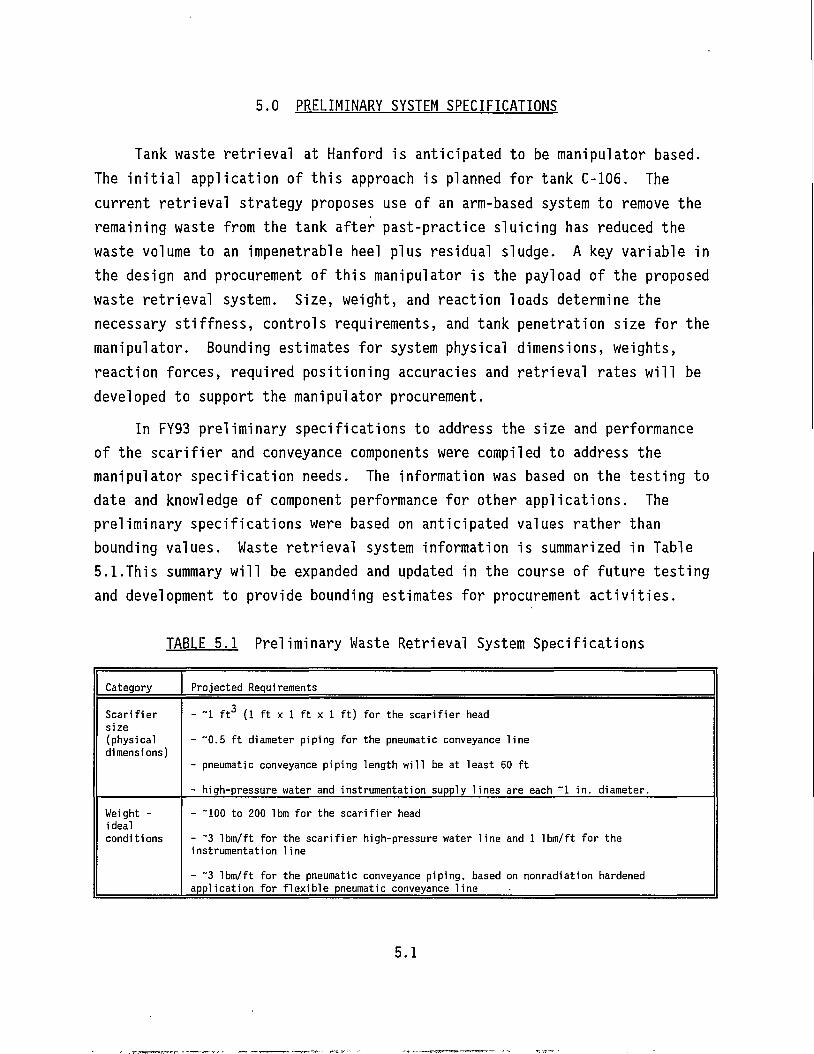
5.0 PRELIMINARY SYSTEM SPECIFICATIONS
Tank waste retrieval at Hanford is anticipated to be manipulator based. The initial application of this approach is planned for tank C-106. The current retrieval strategy proposes use of an arm-based system to remove the remaining waste from the tank after past-practice sluicing has reduced the waste volume to an impenetrable heel plus residual sludge. A key variable in the design and procurement of this manipulator is the payload of the proposed waste retrieval system. Size, weight, and reaction loads determine the necessary stiffness, controls requirements, and tank penetration size for the manipulator. Bounding estimates for system physical dimensions, weights, reaction forces, required positioning accuracies and retrieval rates will be developed to support the manipulator procurement.
In FY93 preliminary specifications to address the size and performance of the scarifier and conveyance components were compiled to address the manipulator specification needs. The information was based on the testing to date and knowledge of component performance for other applications. The preliminary specifications were based on anticipated values rather than bounding values. Waste retrieval system information is summarized in Table 5.1.This summary will be expanded and updated in the course of future testing and development to provide bounding estimates for procurement activities.
TABLE 5.1 Preliminary Waste Retrieval System Specifications
Category Projected Requirements
Scarifier size (physical dimensions)
- ~1 ft 3 (1 ft x 1 ft x 1 ft) for the scarifier head
- ~0.5 ft diameter piping for the pneumatic conveyance line
- pneumatic conveyance piping length will be at least 60 ft
- high-pressure water and instrumentation supply lines are each ~1 in. diameter. Weight -ideal conditions
- "100 to 200 Ibm for the scarifier head - "3 Ibm/ft for the scarifier high-pressure water line and 1 lbm/ft for the instrumentation line - "3 lbm/ft for the pneumatic conveyance piping, based on nonradiation hardened application for flexible pneumatic conveyance line
5.1
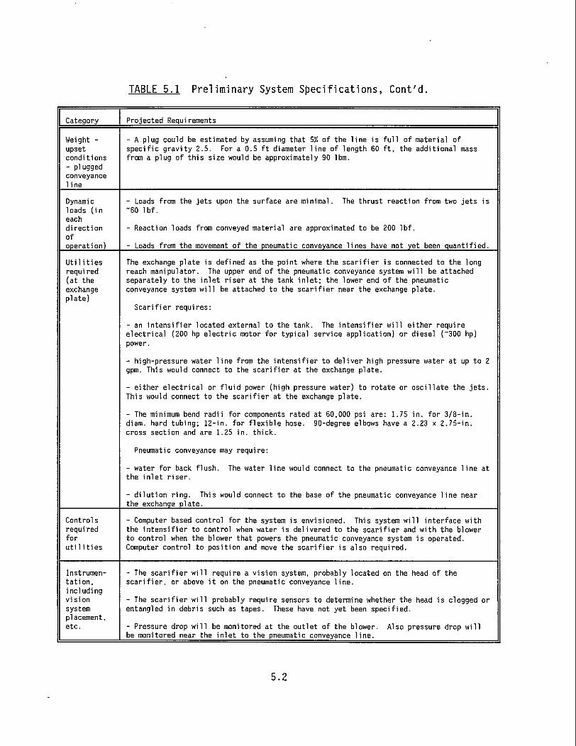
TABLE 5.1 Preliminary System Specifications, Cont'd.
Category Projected Requirements
Weight -upset conditions - plugged conveyance 1 ine
- A plug could be estimated by assuming that 5% of the line is full of material of specific gravity 2.5. For a 0.5 ft diameter line of length 60 ft, the additional mass from a plug of this size would be approximately 90 lbm.
Dynami c loads (in each direction of operation)
- Loads from the jets upon the surface are minimal. The thrust reaction from two jets is -60 lbf.
- Reaction loads from conveyed material are approximated to be 200 lbf.
- Loads from the movement of the pneumatic conveyance lines have not yet been quantified.
Utilities requi red (at the exchange plate)
The exchange plate is defined as the point where the scarifier is connected to the long reach manipulator. The upper end of the pneumatic conveyance system will be attached separately to the inlet riser at the tank inlet; the lower end of the pneumatic conveyance system will be attached to the scarifier near the exchange plate.
Scarifier requires:
- an intensifier located external to the tank. The intensifier will either require electrical (200 hp electric motor for typical service application) or diesel ("300 hp) power.
- high-pressure water line from the intensifier to deliver high pressure water at up to 2 gpm. This would connect to the scarifier at the exchange plate.
- either electrical or fluid power (high pressure water) to rotate or oscillate the jets. This would connect to the scarifier at the exchange plate.
- The minimum bend radii for components rated at 60,000 psi are: 1.75 in. for 3/8-in. diam. hard tubing; 12-in. for flexible hose. 90-degree elbows have a 2.23 x 2.75-in. cross section and are 1.25 in. thick.
Pneumatic conveyance may require:
- water for back flush. The water line would connect to the pneumatic conveyance line at the inlet riser.
- dilution ring. This would connect to the base of the pneumatic conveyance line near the exchange plate.
Controls required for utilities
- Computer based control for the system is envisioned. This system will interface with the intensifier to control when water is delivered to the scarifier and with the blower to control when the blower that powers the pneumatic conveyance system is operated. Computer control to position and move the scarifier is also required.
Instrumentation, including vision system placement, etc.
- The scarifier will require a vision system, probably located on the head of the scarifier, or above it on the pneumatic conveyance line.
- The scarifier will probably require sensors to determine whether the head is clogged or entangled in debris such as tapes. These have not yet been specified.
- Pressure drop will be monitored at the outlet of the blower. Also pressure drop will be monitored near the inlet to the pneumatic conveyance line.
5.2
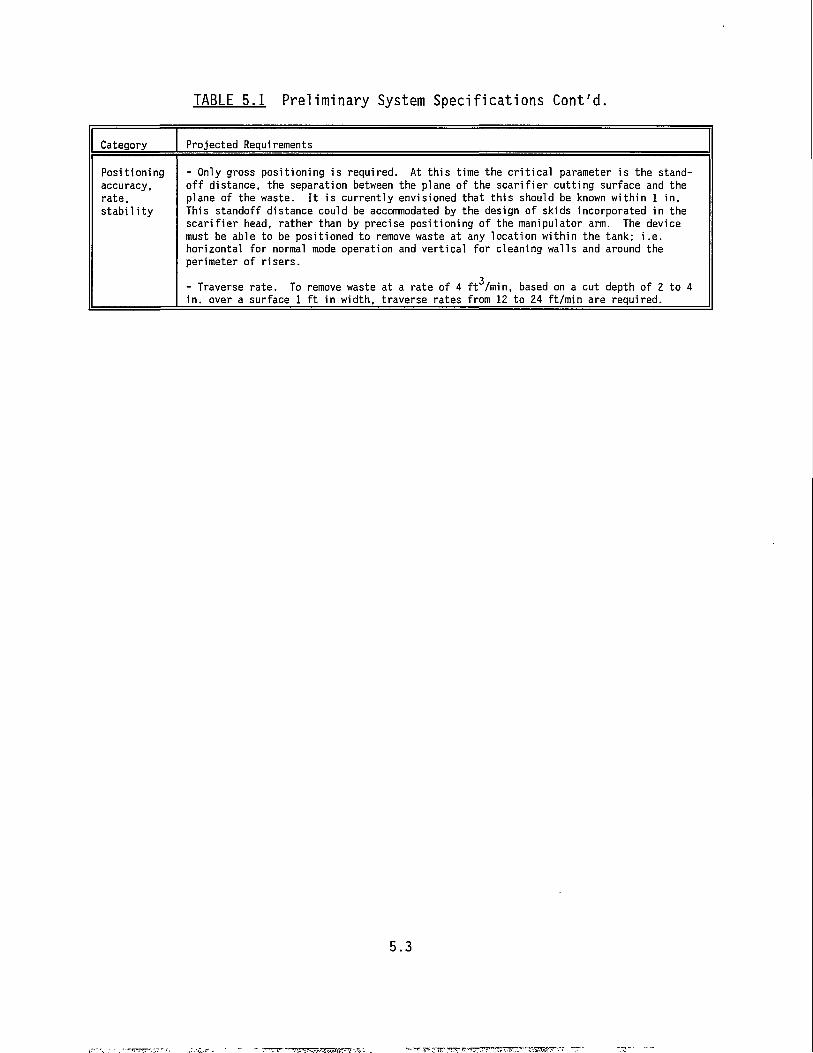
TABLE 5.1 Preliminary System Specifications Cont'd.
Category Projected Requirements
Positioning - Only gross positioning is required. At this time the critical parameter is the stand-accuracy, off distance, the separation between the plane of the scarifier cutting surface and the rate, plane of the waste. It is currently envisioned that this should be known within 1 in. stability This standoff distance could be accommodated by the design of skids incorporated in the
scarifier head, rather than by precise positioning of the manipulator arm. The device must be able to be positioned to remove waste at any location within the tank; i.e. horizontal for normal mode operation and vertical for cleaning walls and around the perimeter of risers.
- Traverse rate. To remove waste at a rate of 4 ft /min, based on a cut depth of 2 in. over a surface 1 ft in width, traverse rates from 12 to 24 ft/min are required.
to 4
5.3
6.0 FY94 PLANS
The scarifier/conveyance investigation began in FY93 with the objective of developing a scarifier ultra-high-pressure jet dislodger coupled with pneumatic transport retrieval for remediation of single-shell tanks. In FY94 the task objective has been expanded to include another waste dislodging and conveyance system. The FY94 effort will increase our fundamental understanding of the mechanics of dislodging, mobilizing and conveying waste for the two waste dislodging and conveyance system combinations. The two systems are:
1). scarifier (ultra-high-pressure water jet: 40,000 to 50,000 psi) coupled with pneumatic transport
2) miner (medium-pressure water jet: 5,000 to 11,000 psi) coupled with jet pump transport. The performance of two dislodgers and two conveyance systems will be
investigated in experiments to 1) develop parametric data to define open issues necessary to resolve prior
to system design and specification and 2) recommend specifications for a design that can be tested in the
integrated test bed and deployed in a waste tank environment. The investigations are coordinated by the Waste Dislodging and Conveyance Mechanics task.
A team consisting of PNL, Quest Integrated, Inc., University of Missouri-Rolla and Dr. Clayton T. Crowe from Washington State University are collaborating during design and testing of the dislodgers and conveyance systems. PNL is leading the team and is responsible for conveyance and integrated system testing. Dr. Crowe acts as a consultant to provide independent technical review, expertise on issues associated with multiphase transport, and support development efforts.
Quest will continue the scarifier ultra-high-pressure water jet investigations. University of Missouri-Rolla will continue miner medium-pressure water jet investigations and jet pump conveyance development. PNL
6.1
will continue the pneumatic conveyance and integrated scarifier/conveyance development.
6.2
REFERENCES
Bamberger, J. A. and D. E. Steele. 1993. "Developing a Scarifier to Retrieve Radioactive Waste from Hanford Single-Shell Tanks," Proceedings of the 7th American Water Jet Conference, M. Hashish, ed., Water Jet Technology Association, St. Louis, Missouri, pp. 737-745. Bamberger, J. A., J. M. Bates, J. K. Keska, M. R. Elmore, and N. J. Lombardo. 1993. Strategy Plan: Strategy to Develop and Test a Multi-Function Scarifier End Effector with an Integral Conveyance System for Waste Tank Remediation, PNL-8477, Pacific Northwest Laboratory, Richland, Washington. Crow, S. C. 1973. "A Theory of Hydraulic Rock Cutting," Int. J. Rock Mech. Min. Sci. & Geomech. Abstr., Pergamon Press, Great Britain, Vol 10, pp. 567-584. Pezzimenti, D. M., P. M. Vlad, and B. Landau. 1989. The Use of the Deep Kerfer for Thick, Steel-Reinforced Concrete Cutting. DOE/NE/44139-58. West Valley Nuclear Services Co., Inc., West Valley, New York. Quest Integrated, Inc. 1990. Water.iet and Air.iet Scarifier Testing For Removal and Decontamination of Radioactive and Hazardous Waste, TR-511/11-90. Kent, Washington. Tundo, D., R. F. Gessner, and R. E. Lawrence. 1988. Lessons Learned at West Vallev During Facility Decontamination for Re-Use. DOE/NE/44139-54. West Valley Nuclear Services Co., Inc., West Valley, New York.
7.1
PNL-8901 AD-902
DISTRIBUTION
No. of Copies
OFFSITE
2 DOE/Office of Scientific and Technical Information
Sherry Gibson DOE HQ 12800 Middle Brook Road Suite 400 Germantown, MD 20874
D. A. Alberts Quest Integrated, Inc. 21414-68th Ave. South Kent, WA 98032
B. Burks Oak Ridge National Laboratory Oak Ridge, TN 37831-6304
C. Christensen Idaho National Eng. Laboratory PO Box 1625 Idaho Falls, ID 83415-3710
Dr. Clayton T. Crowe Department of Mechanical and Material Engineering Washington State University Pullman, WA 99163
D. 0. Monserud Quest Integrated, Inc. 21414-68th Ave. South Kent, WA 98032
No. of Copies
D. E. Steele Quest Integrated, Inc. 21414-68th Ave. South Kent, WA 98032
D. A. Summers University of Missouri-Rolla High Pressure Waterjet Lab Roll a, M0 65401
ONSITE
2 DOE Richland Operations Office
D. E. Trader K8-50 D. A. Brown K8-50
5 Westinqhouse Hanford Company
R. C. Eschenbaum Nl-21 P. W. Gibbons S4-58 0. D. Mullen L5-08 E. J. Shen S4-58 J. A. Yount L5-08
18 Pacific Northwest Laboratory
Bamberger K7-15 (5) Bates K7-15 Enderlin K7-15 Golcar P7-19 Hatchell K5-26 Liljegren K7-15 McKinnon P8-10 Rinker K5-26
Publishing Coordination Technical Report Files (5)
J. A. J. M. c. W. G. R. B. K. L. M. M. A. M. W.
Dist.l


![642-902 exam questions - updated 642-902 test questions [Infographic]](https://img.pdfslide.net/doc/110x75/58e7676d1a28ab5b2a8b656f/642-902-exam-questions-updated-642-902-test-questions-infographic.jpg)
![ΑΝΤΙΣΤΡΟΦΟ [902] ΛΕΞΙΚΟ [ΜΕΣΑΙΩΝΙΚΟ ΓΛΩΣΣΑΡΙΟ] [Α-Ω] [902] ΜΕΡΣΙΟΥ.pdf](https://img.pdfslide.net/doc/110x75/577c7d991a28abe0549f5d01/-902--578131b7b4359.jpg)