Embed Size (px)
Citation preview
AD-A254 960FLOOD CONTROL STRUCTURES 9
RESEARCH PROGRAM
TECHNICAL REPORT HL-92-5
RIPRAP STABILITY: STUDXESIN NEAR-PROTOTYPE SIZE
LABORATORY CHANNEL
by
Stephen T. Maynord
Hydraulics Laboratory
DEPARTMENT OF THE ARMY_Waterways Experiment Station, Corps of Engineers
3909 Halls Ferry Road, Vicksburg, Mississippi 39180-6199
ELEOTEAUG 2 5 195 iI
June 1992'7). Final Report
SC • •'Approved For Public Release; Distribution Is Unlimited
NPrepared for DEPARTMENT OF THE ARMYHYDRAULICS US Army Corps of Engineers
Wasrington, DC 20314-1000
Under Civil-VVrs Investigation Work Unit 32541LABORATORY 1,?

PAGESARE
MISSINGIN
ORIGINALDOCUMENT
Destroy this report when no longer needed. Do not returnit to th' originator.
The findings in this report are not to be construed as an officialDepartment of the Army position unless so designated
by other authorized documents.
The contents of this report are not to be used foradvertising, publication, or promotional purposes.Citation of trade names does not constitute anofficial endorsement or approval of the use of
such commercial products.
Form ApprovedREPORT DOCUMENTATION PAGE 0MB No. 0704-0188
Public reotn budf a his collectcin of information i estimated to aragei hour per rewnse. incluing the timne for revewn instructions. searching existing data sources.gath@ri" dmat= n0inghe data needed, and comlett• reiew lection of in ormation. endcomments rega•dingthis burden estimate or any other 28spe Of this
collection of information. includi ng%.w tions for reducing this burden. to Washington ifeadkuarters Services. Directorate for Information Operations, and Repons. I5 JersJCfferon
Davis Highway. Suite 1204. Arlington. VA 2202 4302. and to the Office of Management and Budget. Paperwork Reduction Project (0704-01f8). Washington. DC 20503
1. AGENCY USE ONLY (Leave blank) 2. REPORT DATE 3. REPORT TYPE AND DATES COVERED
IJune 1992 Final report4. TITLE AND SUBTITLE 5. FUNDING NUMBERS
iprap Stability: Studies in Near-Prototype Size WU 32541boratory Channel
6. AUTHOR(S)
tephen T. Maynord
7. PERFORMING ORGANIZATION NAME(S) AND ADDRESS(ES) B. PERFORMING ORGANIZATIONREPORT NUMBER
SAE Waterways Experiment Station, Hydraulics Technical Reportboratory, 3909 Halls Ferry Road, Vicksburg, MS HL-92-5
39180-61999. SPONSORING/ MONITORING AGENCY NAME(S) AND ADDRESS(ES) 10. SPONSORING /MONITORING
AGENCY REPORT NUMBERUS Army Corps of Engineers, Washington, DC 20314-1000
11. SUPPLEMENTARY NOTES
Available from National Technical Information Service, 5285 Port Royal Road,,Springfield, VA 22161.12a. DISTRIBUTION /AVAILABILITY STATEMENT 12b. DISTRIBUTION CODE
Approved for public release; distribution is unlimited.
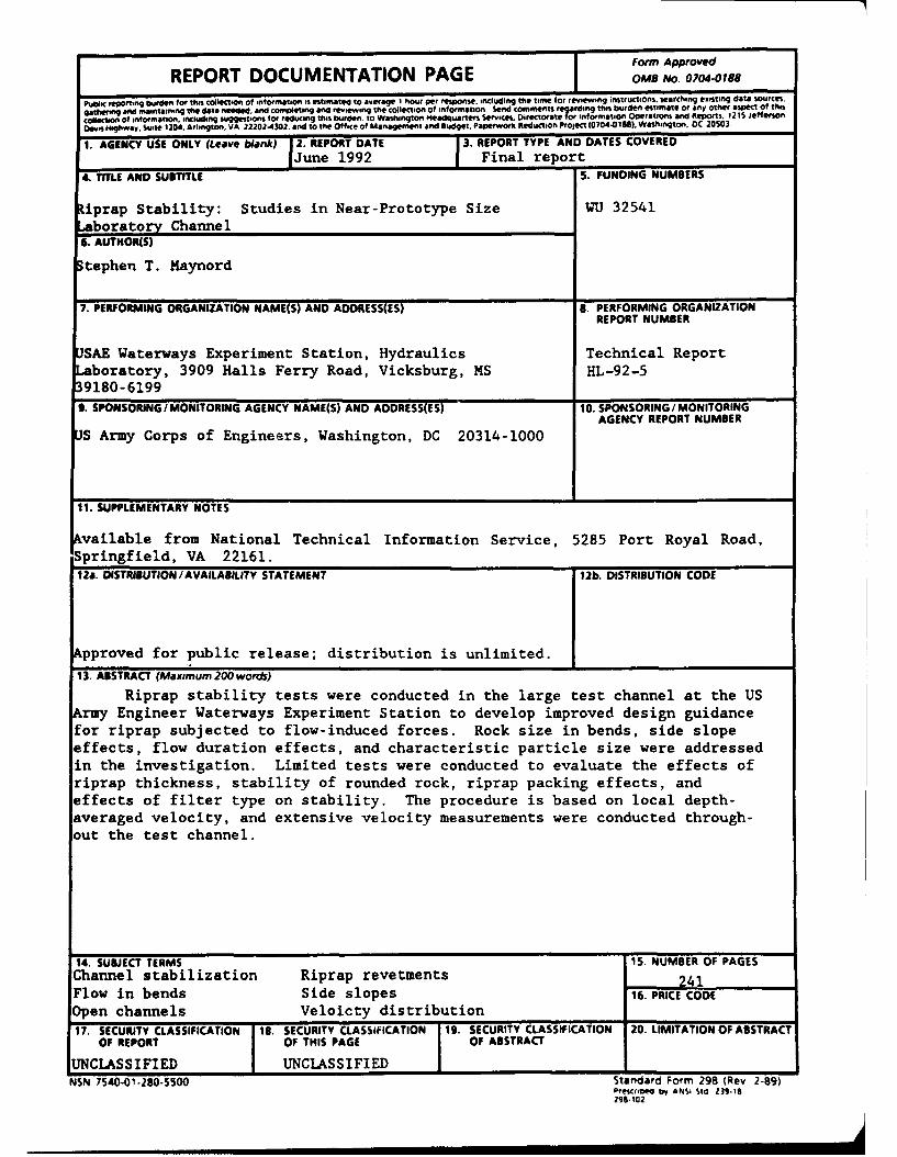
13. ABSTRACT (Maximum 200 words)
Riprap stability tests were conducted in the large test channel at the USArmy Engineer Waterways Experiment Station to develop improved design guidancefor riprap subjected to flow-induced forces. Rock size in bends, side slopeeffects, flow duration effects, and characteristic particle size were addressedin the investigation. Limited tests were conducted to evaluate the effects ofriprap thickness, stability of rounded rock, riprap packing effects, andeffects of filter type on stability. The procedure is based on local depth-averaged velocity, and extensive velocity measurements were conducted through-out the test channel.
14. SUBJECT TERMS 15. NUMBER OF PAGESChannel stabilization Riprap revetments 241Flow in bends Side slopes 16. PRICE CODEOpen channels Veloicty distribution17. SECURITY CLASSIFICATION '1B. SECURITY CLASSIFICATION 19. SECURITY CLASSIFICATION 20. LIMITATION OF ABSTRACT
OF REPORT OF THIS PAGE OF ABSTRACT
UNCLASSIFIED UNCLASSIFIED INSN 7540-01-280-5500 Standard Form 298 (Rev 2-89)
Prescrie by ANSI Sid 139-18298.102
PREFACE
The study described herein was performed by personnel of the Hydraulics
Laboratory, US Army Engineer Waterways Experiment Station (WES), during the
period 1987-1991. It was sponsored by Headquarters, US Army Corps of
Engineers (HQUSACE), as part of the Flood Control Structures Research Programunder Civil Works Investigation Work Unit 32541, "Riprap Design and Cost
Reduction: Studies in Near Prototype Size Laboratory Channel." HQUSACE
Program Monitor was Mr. Tom Munsey.
This study was accomplished under the direction of Messrs. f. A.Herrmann, Jr., Chief of the Hydraulics Laboratory; R. A. Sager, AssistantChief of the Hydraulics Laboratory; and G. A. Pickering, Chief of the
Hydraulic Structures Division, Hydraulics Laboratory. The tests were
conducted by Dr. S. T. Maynord, project engineer, and Messrs. D. M. White and
J. T. Hilbun, Spillways and Channels Branch, Hydraulic Structures Division,under the direct supervision of Mr. N. R. Oswalt, Chief of the Spillways and
Channels Branch. This report was written by Dr. Maynord and edited by
Mrs. Marsha Gay, Information Technology Laboratory, WES.
At the time of publication of this report, Director of WES was
Dr. Robert W. Whalin. Commander and Deputy Director was COL Leonard G.
Hassell, EN.
-- . .. , m • I i mml mm miIN m i m1
CONTENTS
Page
PREFACE .................................................................... 1
CONVERSION FACTORS, NON-SI TO SI (METRIC) UNITS OF MEASUREMENT ......... 3
PART I: INTRODUCTION ..................................................... 4
Background ........................................................... 4Purpose and Scope .................................................... 6
PART II: BASIC EQUATIONS ................................................. 7
PART III: EXPERIMENTAL INVESTIGATION ...................................... 9
Riprap Characteristics ................................................ 9Test Procedure ................................................... 9Data Presentation .................................................... 10
PART IV: ANALYSIS AND RESULTS ............................................ 12
Characteristic Particle Size ........................................ 12Side Slope Angle Effects ............................................ 14Flow Duration Effects on Riprap Stability .......................... 14Characteristic Velocity for Side Slopes ............................. 16Riprap Size in Channel Bends ........................................ 17Bottom Riprap Tests .................................................. 19Riprap Thickness Effects ............................................ 20Stability of Rounded Rock ........................................... 21Effects of Riprap Packing ........................................... 22Effects of Filter Type ............................................... 22
PART V: SUMMARY AND CONCLUSION .......................................... 24
REFERENCES .................................................................. 25
TABLES 1-14
PLATES 1-18
APPENDIX A: VELOCITIES .................................................... Al
APPENDIX B: DESCRIPTION OF ROCK MOVEMENT AND FAILURE .................. BI
APPENDIX C: NOTATION ...................................................... Cl
2
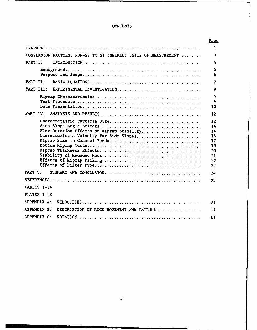
CONVERSION FACTORS, NON-SI TO SI (METRIC)
UNITS OF MEASUREMENT
Non-SI units of measurement used in this report can be converted to SI
(metric) units as follows:
. Multiply By To Obtain
cubic feet 0.02831685 cubic metres
degrees (angle) 0.01745329 radians
degrees Fahrenheit 5/9 Celsius degrees orkelvins*
feet 0.3048 metres
inches 2.54 centimetres
pounds (mass) 0.4535924 kilograms
pounds (mass) per 16.01846 kilograms per cubiccubic foot metre
Accesion ForNTIS C,,&I
UT1C [ 'J,.
ByD: - t i :" "
Uit I
* To obtain Celsius (C) temperature readings from Fahrenheit (F) readings, usethe following formula: C - (5/9)(F - 32). To obtain Kelvin (K) readings, use:K - (5/9)(F - 32) + 273.15.
3
RIPRAP STABILITY: STUDIES IN NEAR-PROTOTYPE
SIZE LABORATORY CHANNEL
PART I: INTRODUCTION
Backzround
1. The US Army Corps of Engineers spends large amounts on riprap chan-
nel protection each year for the project purposes of flood control and naviga-
tion. In an attempt to reduce both initial and maintenance costs, research
has been underway for a number of years to develop improved guidance for
design of riprap. Riprap design guidance must be applicable to a wide range
of channel cross sections and alignments, hydraulic conditions, riprap grada-
tions, thicknesses, and shapes. However, past experience has shown that any
guidance that is not relatively easy to apply will most likely be discarded in
favor of a simple table relating rock size to velocity. Consequently, this
research has attempted to take the complex problem of riprap stability and
define it in parameters that are easy to apply. The design procedures
developed in this research program have been incorporated into Engineer Manual
(EM) 1110-2-1601 (Headquarters, US Army Corps of Engineers 1991).
2. The first step in achieving ease of application was to discard the
traditional tractive force procedure and use velocity to define the forces
imposed on the riprap. While tractive force is preferred because it attempts
to define the forces on the channel boundary, it has not been widely adopted
by engineers involved in riprap design. Furthermore, determining tractive
force in complex geometries or in areas of high relative roughness or signifi-
cant secondary currents is difficult because the logarithmic relationship
between tractive force and depth-averaged velocity is not applicable. Wave
stability equations have taken a similar approach; wave height is used instead
of a force on the boundary.
3. The second step in achieving ease of application is to accept that
some factors are not yet understood and that their effects are lumped into the
empirical stability coefficients. For example, riprap gradation affects
stability in many ways including the following:
4
a. How significant is size segregation when using a gradationhaving a wide range in sizes.
b. In gradations having a wide range of sizes, are small particlessheltered by larger particles or are they more easily washedaway due to turbulence in the wake of the larger particles?
c. What is the impact of gradation on particle interlock?
While each of these are important factors, they were not addressed
individually in this study. This study accepts that the factors affecting
gradation are complex, and empirical stability coefficients that combine many
of these factors are de-ermined for a range of gradation uniformity.
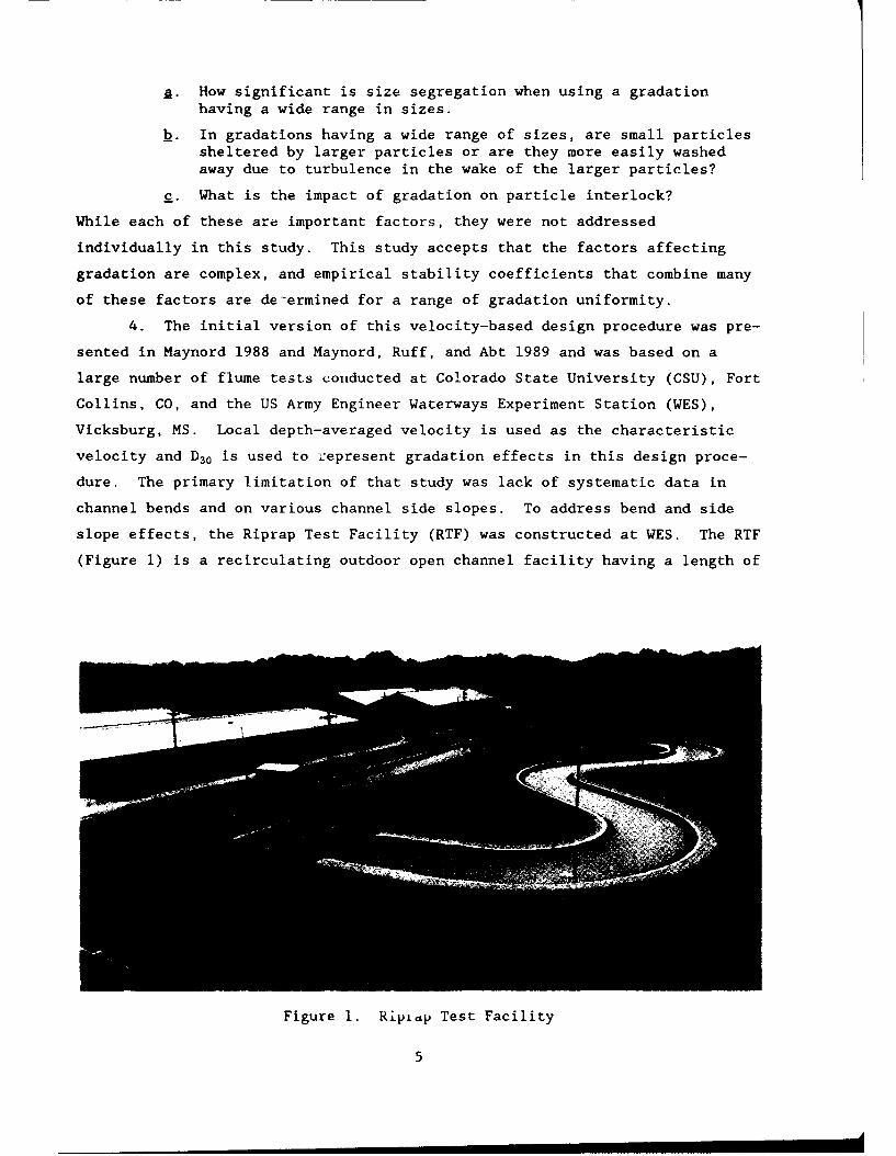
4. The initial version of this velocity-based design procedure was pre-
sented in Maynord 1988 and Maynord, Ruff, and Abt 1989 and was based on a
large number of flume tests conducted at Colorado State University (CSU), Fort
Collins, CO, and the US Army Engineer Waterways Experiment Station (WES),
Vicksburg, MS. Local depth-averaged velocity is used as the characteristic
velocity and D3 0 is used to represent gradation effects in this design proce-
dure. The primary limitation of that study was lack of systematic data in
channel bends and on various channel side slopes. To address bend and side
slope effects, the Riprap Test Facility (RTF) was constructed at WES. The RTF
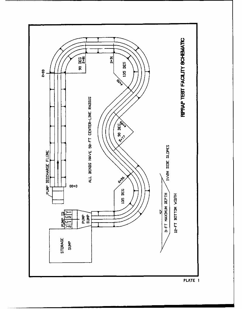
(Figure 1) is a recirculating outdoor open channel facility having a length of
Figure 1. Riptap Test Facility
5
780 ft*, four bendways, and two constant-speed and two variable-speed pumps
that supply a discharge Q of 0-200 cfs. The RTF was initially molded to a
trapezoidal cross section having IV:2H side slopes, 12-ft bottom width,
0.2 percent bottom slope, and 2.5-in.-thick riprap having a maximum stone size
of 2.1 in. on both the bottom and side slopes. The channel schematic is shown
in Plate 1.
Purpose and Scope
5. The objectives of this study are to address the following limita-
tions of the velocity-based procedure presented in Maynord, Ruff, and Abt
(1989):
a. What is the effect of using a single particle size (D3 0 ) tocharacterize a gradation?
b. What is the effect of side slope angle ranging from lV:3H toIV:I.511?
c. What is the influence of flow duration on riprap stability?
d. What is the characteristic velocity for side slopes in bothstraight and curved channels?
e. What is the rock size required on the outer bank of channelbends?
In addition to these objectives, limited tests were conducted to compare bot-
tom riprap stability in the RTF to CSU results, to determine the impacts of
riprap thickness, to evaluate the stability of rounded rock, to determine if
packing riprap improves stability, and to determine the impacts of a granular
filter versus a fabric filter.
A table of factors for converting non-S! "nits of measurement - SI
(metric) units is found on page 3.
6
PART II: BASIC EQUATIONS
6. The basic equation developed by Neill (1967) and presented in
Maynord (1988) is
Dr C V(2j (1)
where
Dr - characteristic particle size*
d - local flow depth
C - coefficient
7. - unit weight of water
73 - unit weight of stone
V - local depth-averaged flow velocity
g - gravitational acceleration
Equation I can be developed from the following equations:
rb = 7. d S (2)
T, C,•8(- - -Y.)Dr (3)
V - 1.49 d 2 / 3 S1 / 2 (4)n
n - C Dr 6 (5)-r
cam _ C(Dr/d)2 /1 5 (6)
where
-- bed shear stress
* For convenience, symbols and unusual abbreviations are listed and defined
in the Notation (Appendix C).
7
S - ei,,rgy slope
T, - crit' 31 tractive force for given particle size on horizontal bed
C. - modi d Shields coefficient
n - Manning's roughness coefficient
The modified Shields coefficient (Equation 6) is conceptually in agreement
with findings of several investigators (Maynord 1988) showing variation of
Shields coefficient with relative roughness. Equation 1 lumps the effects of
velocity profile, turbulence, and Shields stability coefficient into a single
equation. The disadvantage of this approach is that different velocity pro-
files and Shields relationships cannot be easily inserted to make this a more
general procedure such as that proposed by Pilarczyk (1990). The advantage of
this approach is that stability coefficients can be readily determined from
both laboratory ane field data without having to address the interrelated and
complex problems of velocity profile, Shields coefficient, and turbulence
level. The effects of these f :tors are combined into the empirical stability
coefficients.
7. Using tractive force concepts, the tractive force ratio for side
slope K is
K =s (7)Tc
where r, is the critical tractive force on the side slope. Combining Equa-
tions 2-7 results in the following equation, presented in Permanent Interna-
tional Association of Navigation Congresses (1987) and attributed to
Pilarczyk:
12.5Dr -C _Y_ V (8)
Equation 8 will be the basic equation used throughout this investigation.
From Maynord (1988) a characteristic particle size of D30 and a value of C
of 0.30 were determined for bottom riprar in straight channels placed to a
thickness of 1D1 00.
8
PART III: EXPERIMENTAL INVESTIGATION
Riprap Characteristics
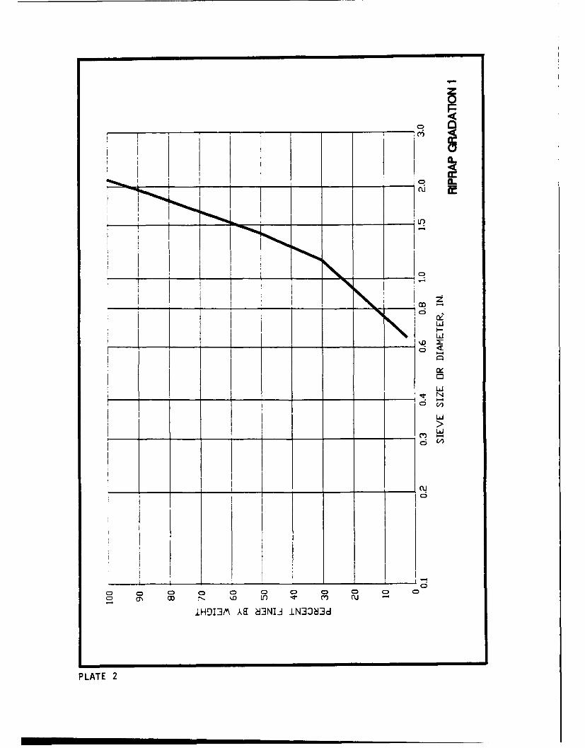
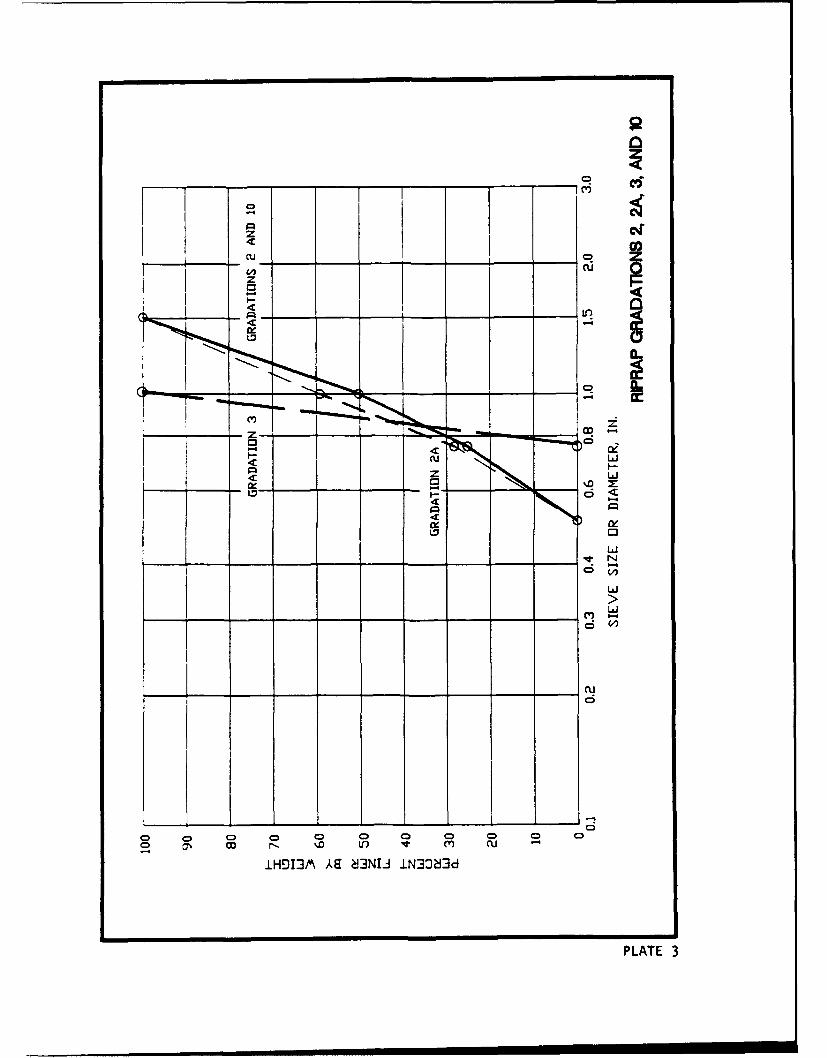
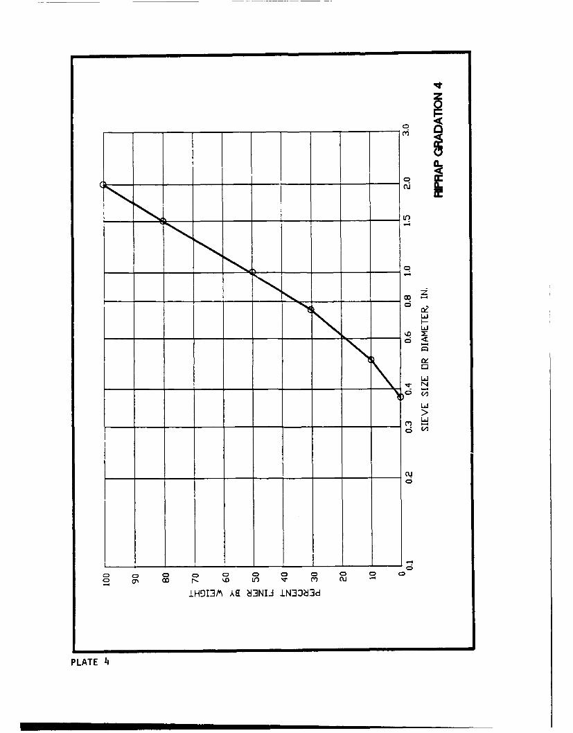
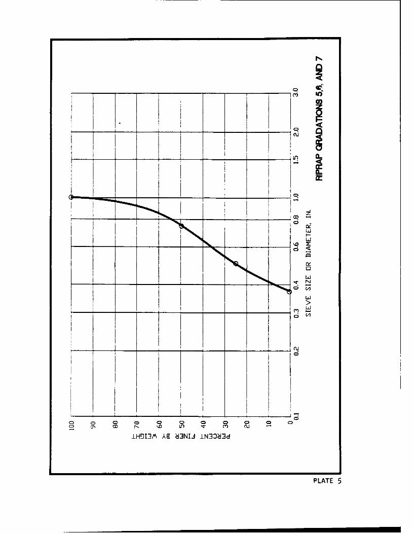
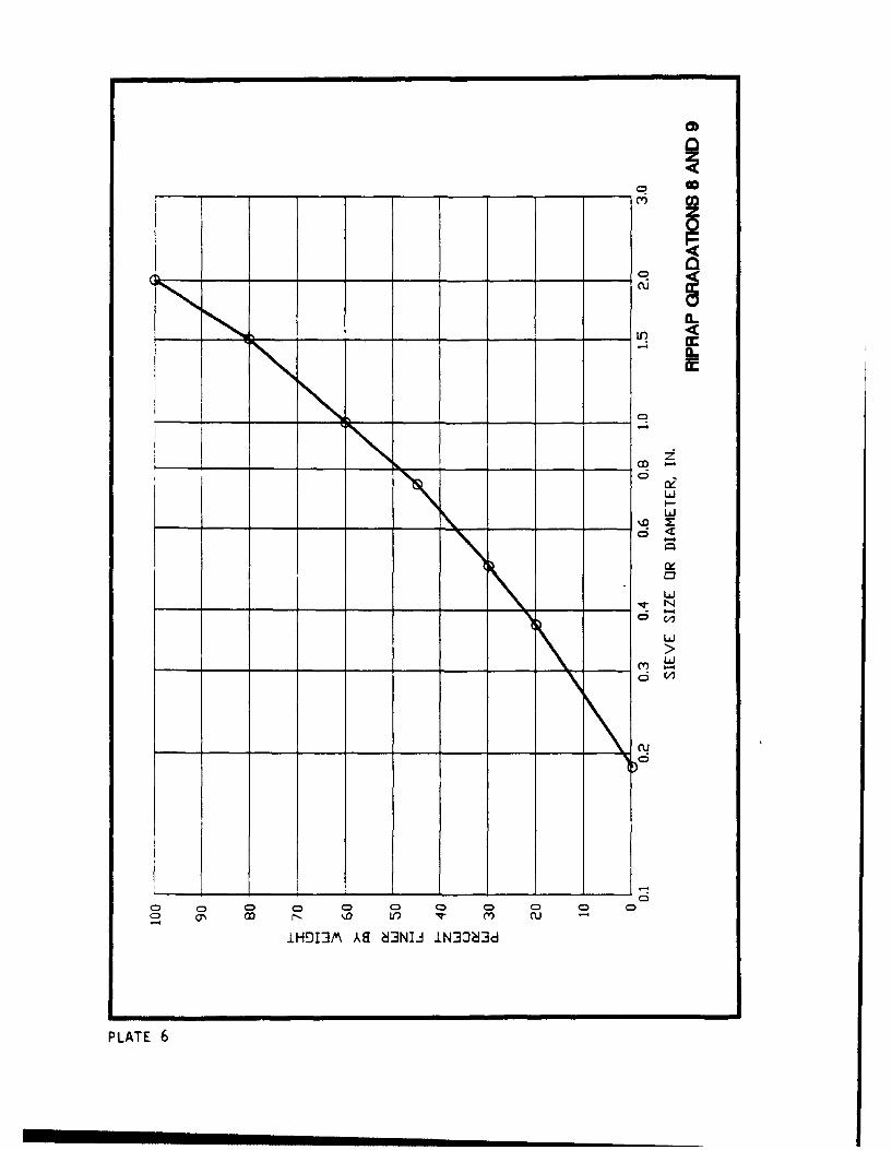
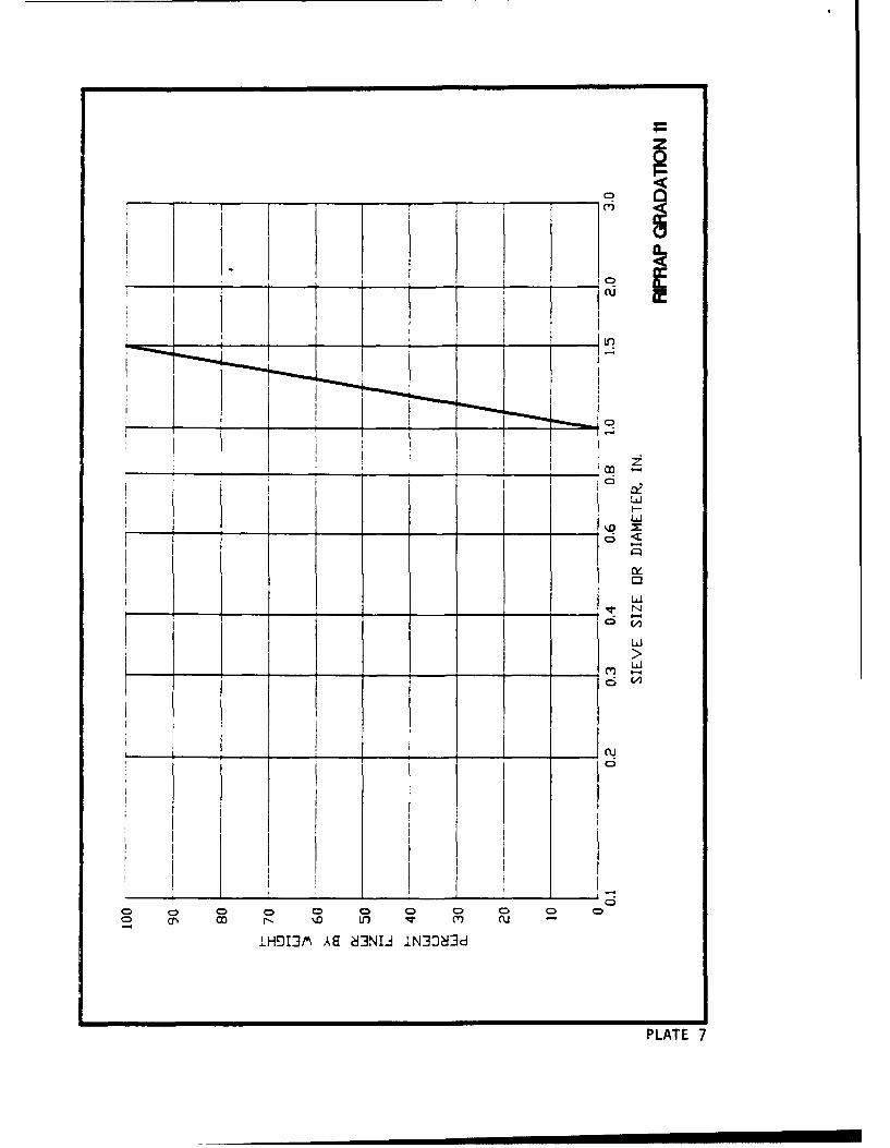
8. The riprap gradations used in this investigation are shown in
Table 1 and Plates 2-7. The shape characteristics of the rock used in grada-
tions 2-9 are shown in Table 2. To determine stone dimensions L and b
consider that the stone has a long axis, an intermediate axis, and a short
axis. Dimension L is the maximum length of the stone, which defines the
long axis of the stone. The intermediate axis is defined by the maximum width
of the stone. The remaining axis, which is perpendicular to the other two
axes, is the short axis. Dimension b is the maximum stone dimension paral-
lel to the short axis. Results of angle of iepose tests for angular rock as a
function of revetment height are shown in Plate 8 along with results from
Ulrich (1987) and Maynord (1988). These tests were conducted with a hinged
plate as described in Ulrich (1987) and Maynord (1988).
Test Procedure
9. The original gradation 1 was placed to a thickness of 1.25 D10 0
throughout the facility. Side slope stability testing of gradations 2-11 took
place in bendways 1 and 3 (bendway 1 is upstream). The gradation to b( tested
was placed from near the upstream end of the bend to the beginning of the next
bend. The riprap was placed on the outer bank side slope and on the channel
bottom for a distance of 2 ft frcm the toe of the outer bank slope. The
remainder of the cross section was left covered with the original gradation 1.
Unless noted, riprap was placed on a nonwoven filter fabric. Riprap placement
in the RTF was intended to simulate placement in the prototype in which the
riprap is dumped close to its final position with a minimum of spreading. No
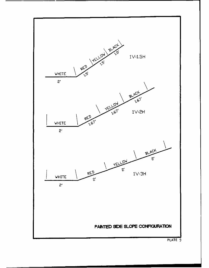
packing or tamping was permitted unless noted. After placement, the riprap
was painted in horizontal strips of different color to facilitate observation
of movement as shown in Figure 2 and Plate 9. For side slope tests with
slopes of IV:l.5H and IV:3H, the outer bank of bendway 1 was remolded to the
desired bank slope keeping the toe of slope in the same location as in the
IV:2H tests. Failure criteria was incipient failure (Maynord 1988), which is
the flow conditions at which the filter fabric begins to be exposed after
9
P1
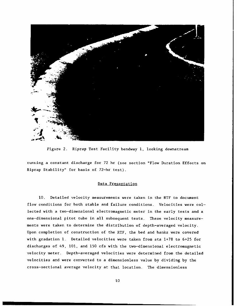
Figure 2. Riprap Test Facility bendway i, looking downstream
running a constant discharge for 72 hr (see section "Flow Duration Effects on
Riprap Stability" for basis of 72-hr test).
Data Presentation
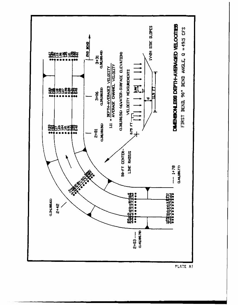
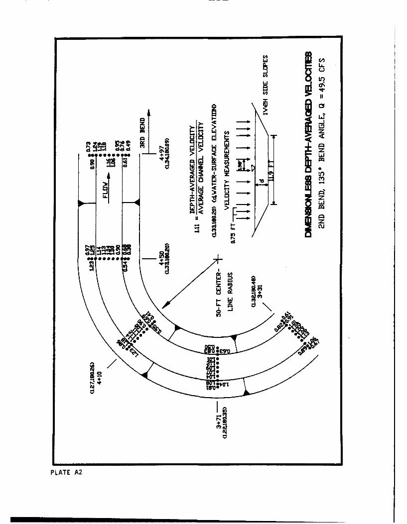
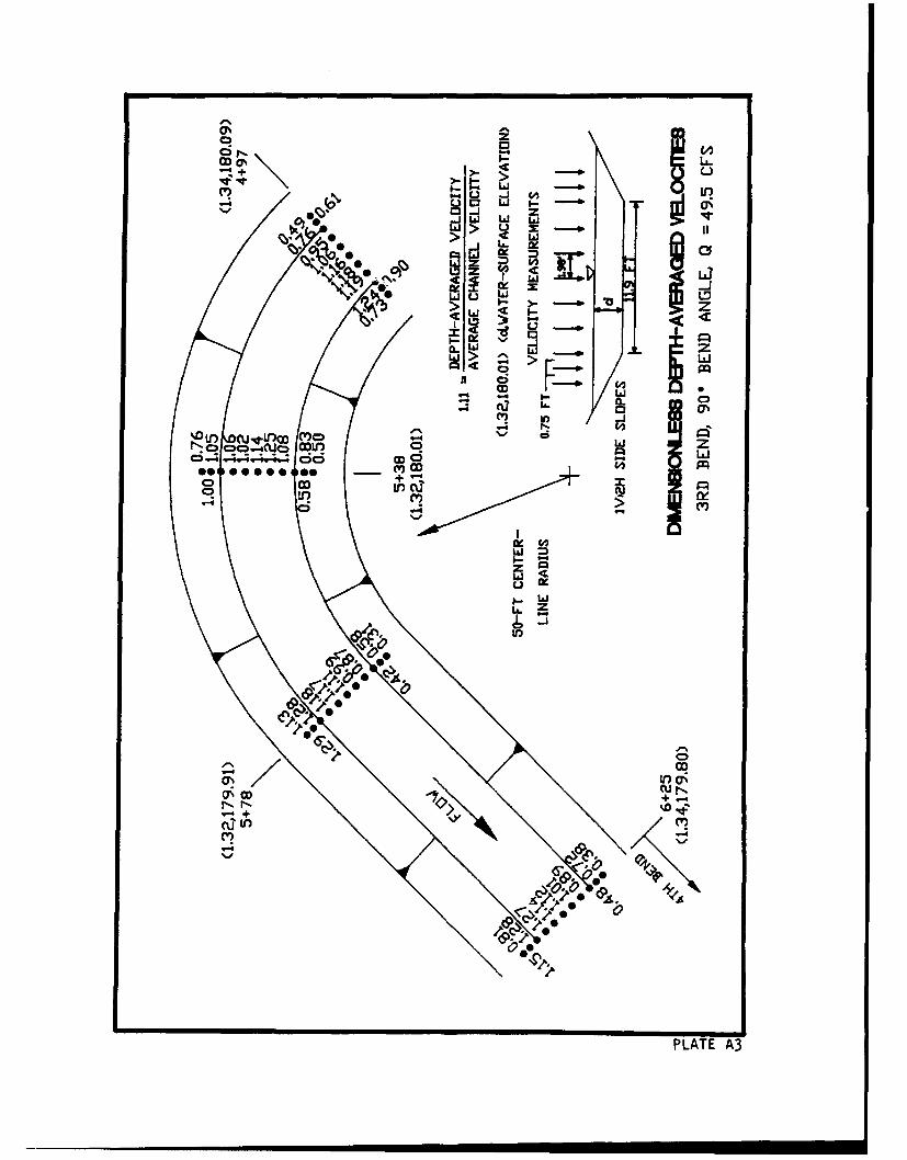
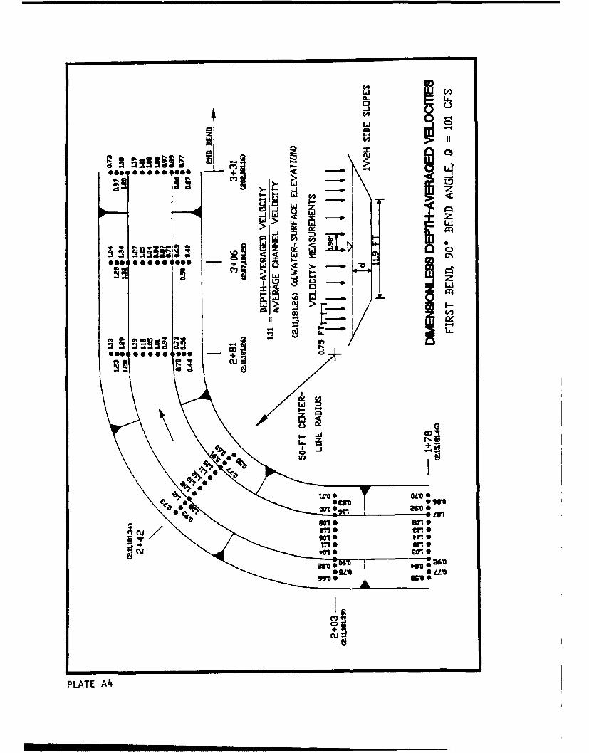
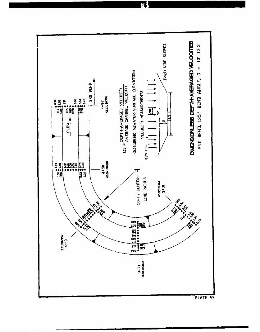
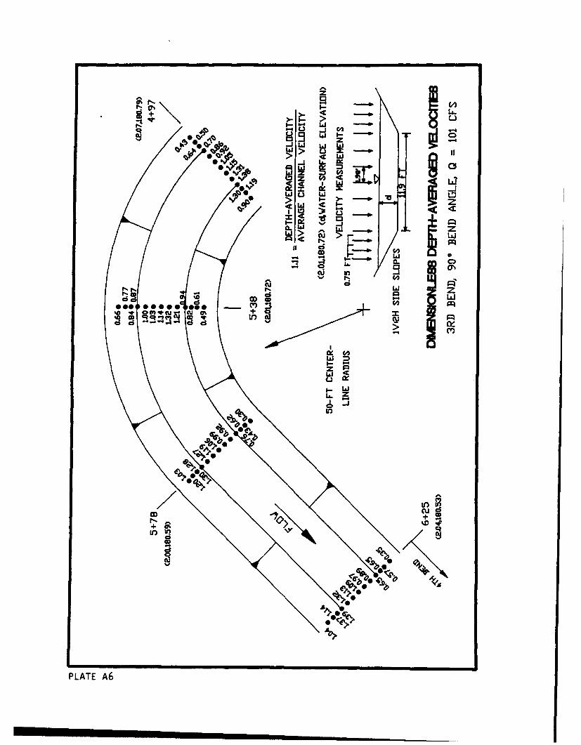
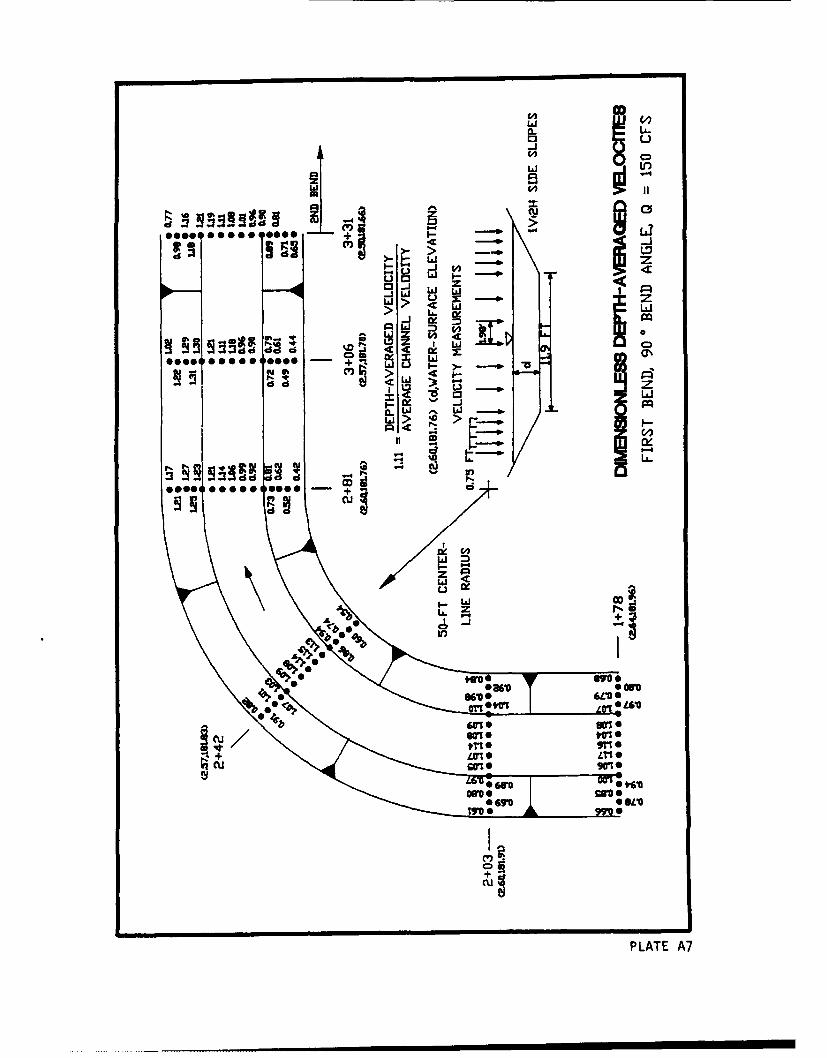
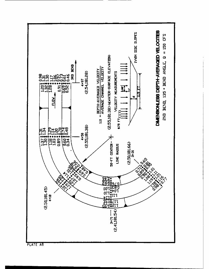
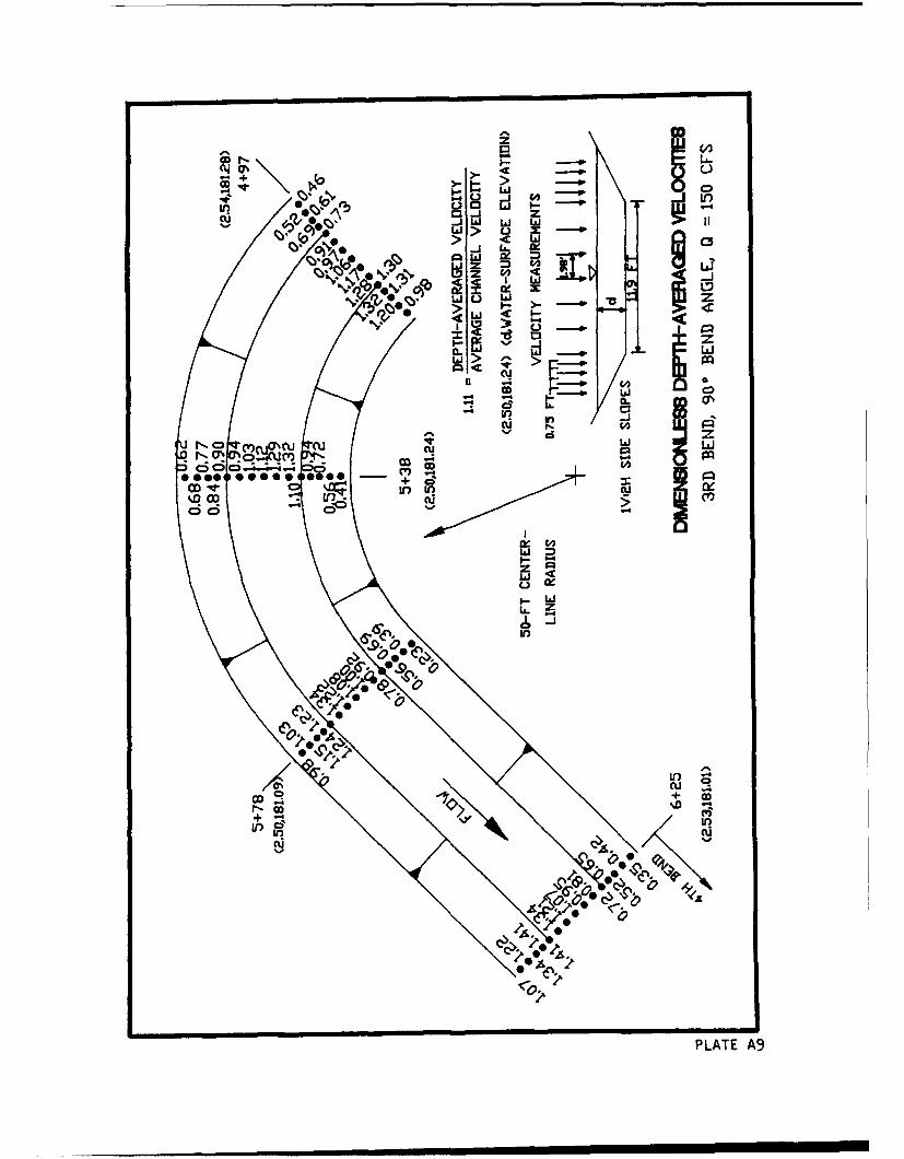
10. Detailed velocity measurements were taken in the RTF to document
flow conditions for both stable and failure conditions. Velocities were col-
lected with a two-dimensional electromagnetic meter in the early tests and a
one-dimensional pitot tube in all subsequent tests. These velocity measure-
ments were taken to determine the distribution of depth-averaged velocity.
Upon completion of construction of the RTF, the bed and banks were covered
with gradation 1. Detailed velocities were taken from sta 1+78 to 6+25 for
discharges of 49, 101, and 150 cfs with the two-dimensional electromagnetic
velocity meter. Depth-averaged velocities were determined from the detailed
velocities and were converted to a dimensionless value by dividing by the
cross-sectional average velocity at that location. The dimensionless
10
depth-averaged velocities for the three discharges are shown in Plates A1-A9.
No riprap failure was observed for any of the three discharges with
gradation 1.
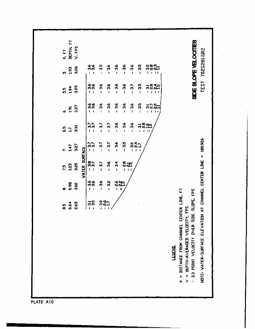
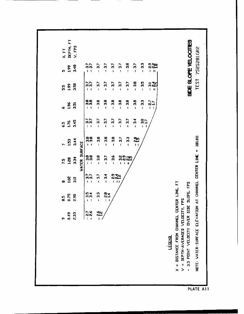
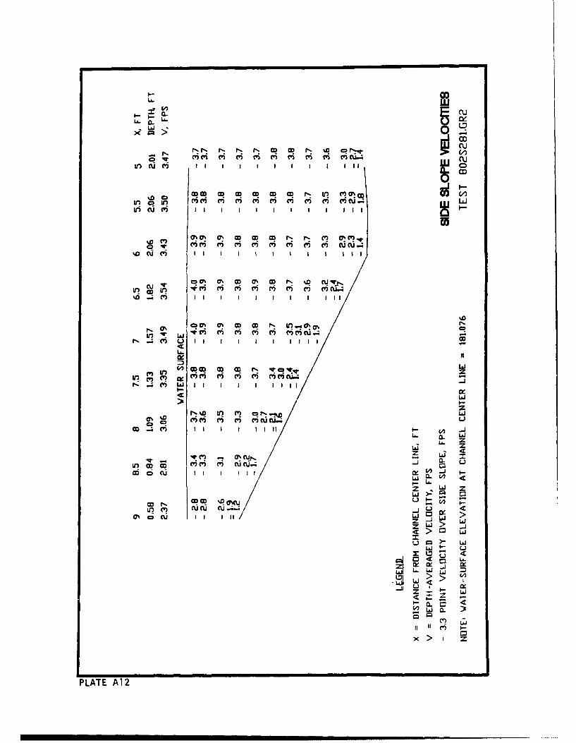
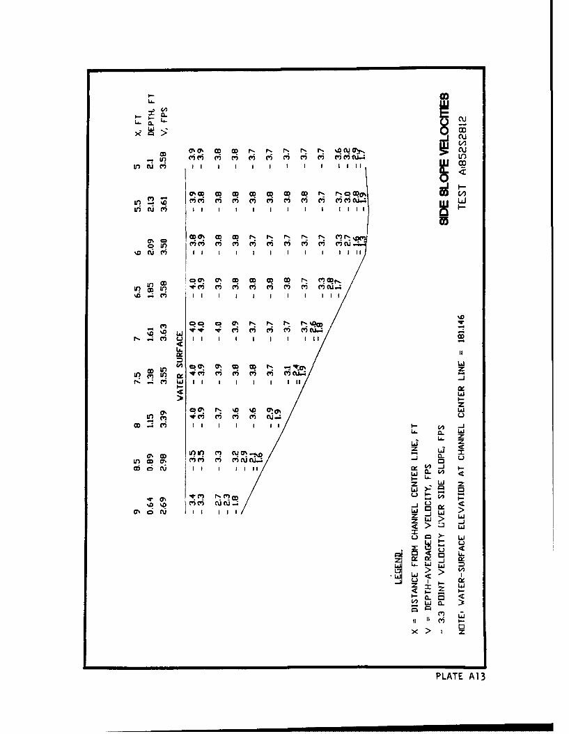
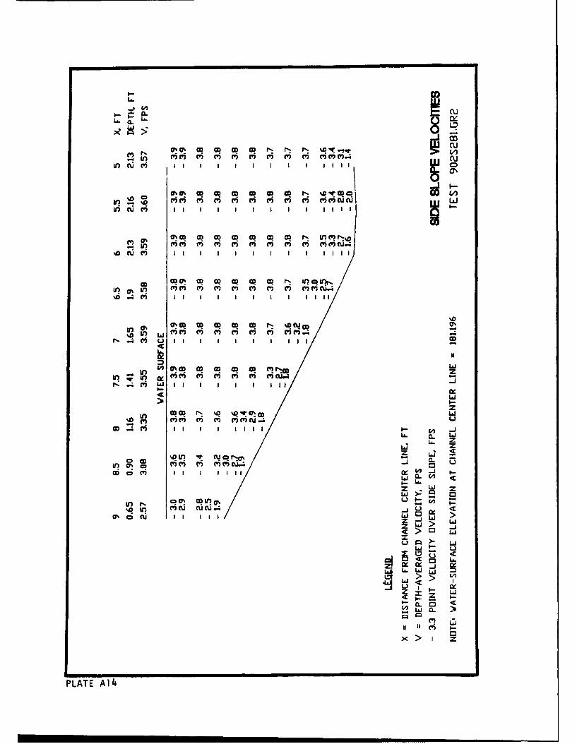
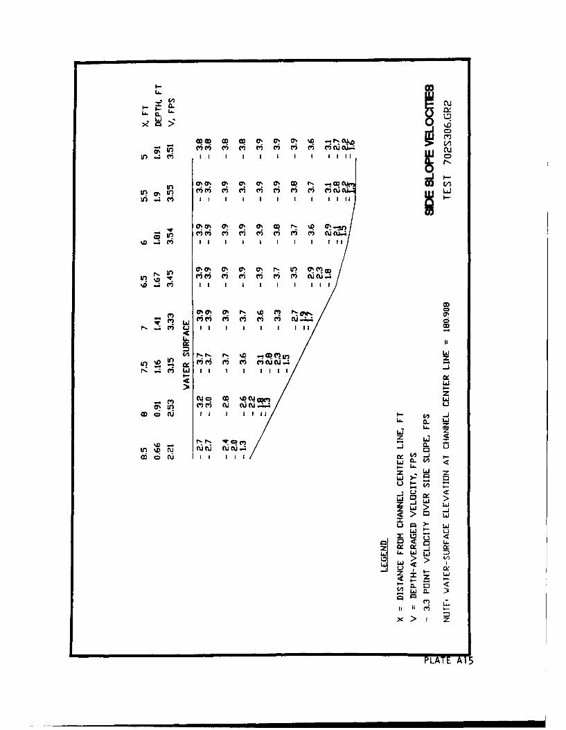
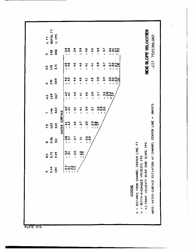
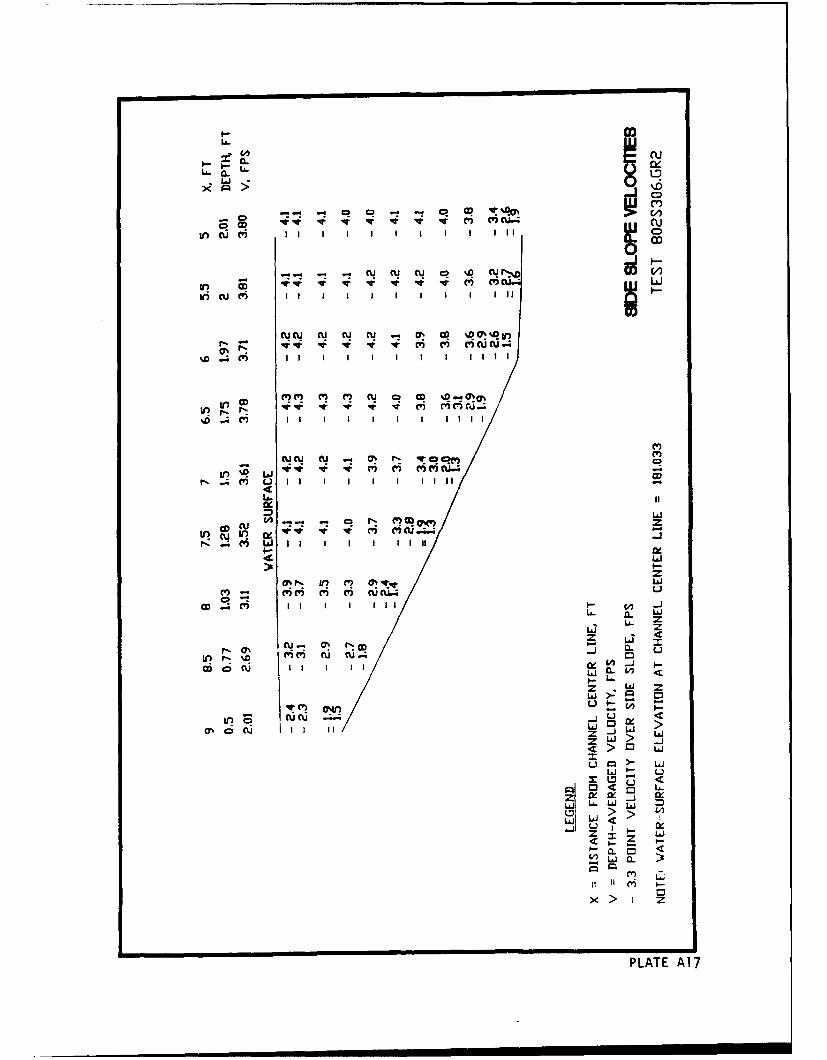
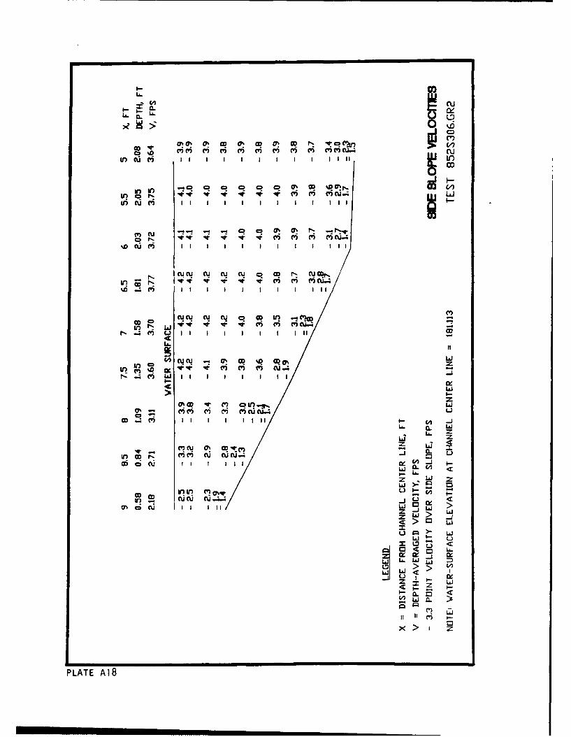
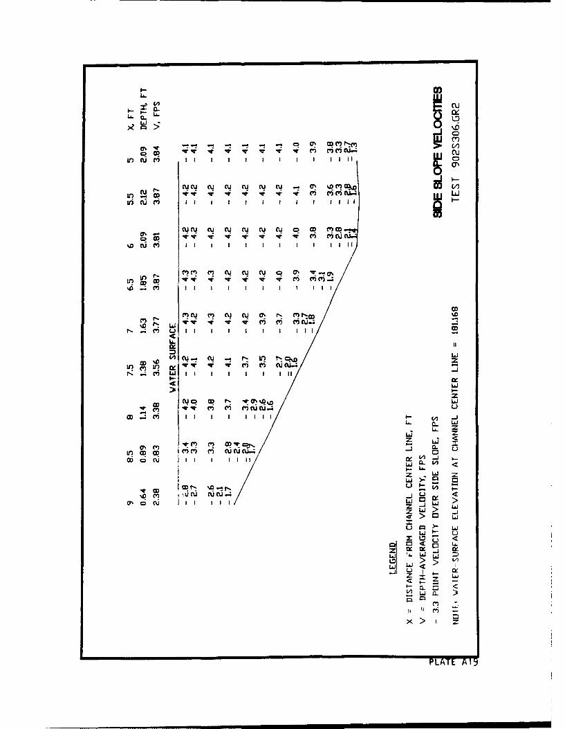
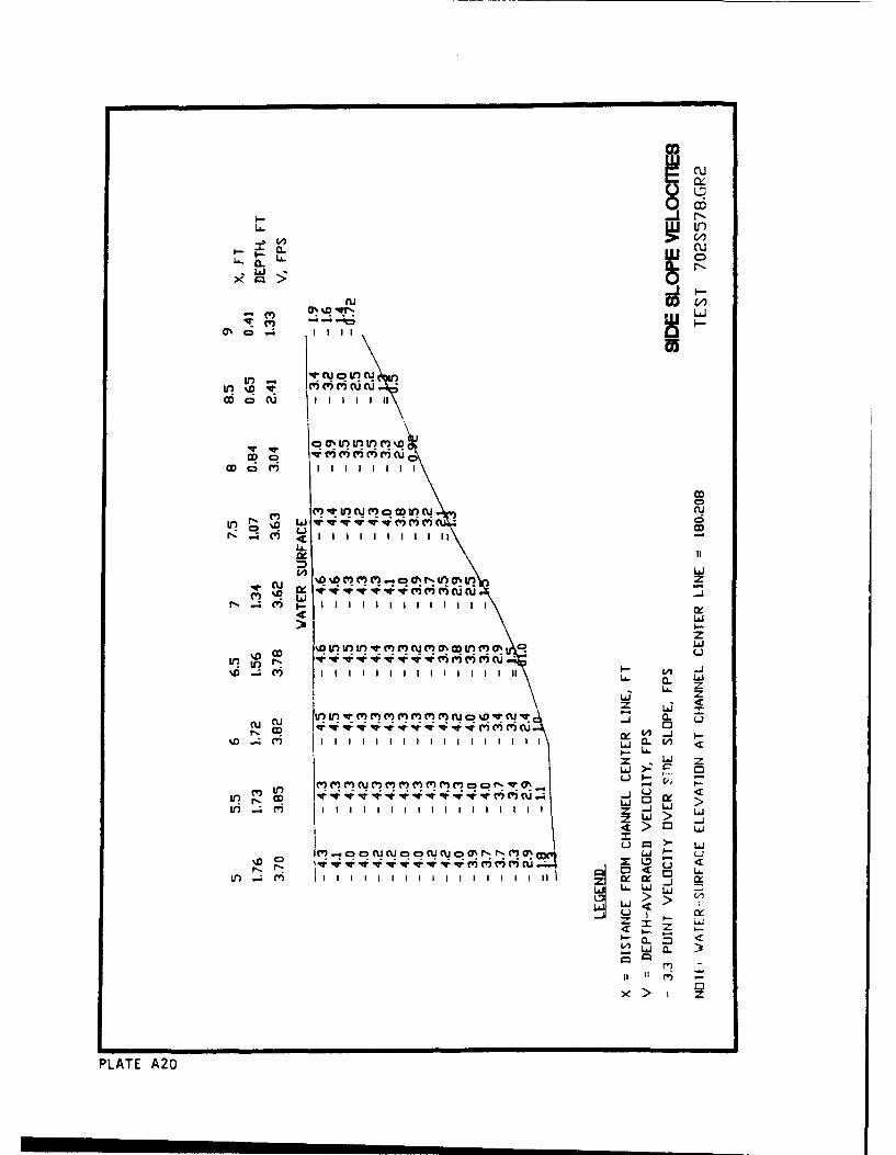
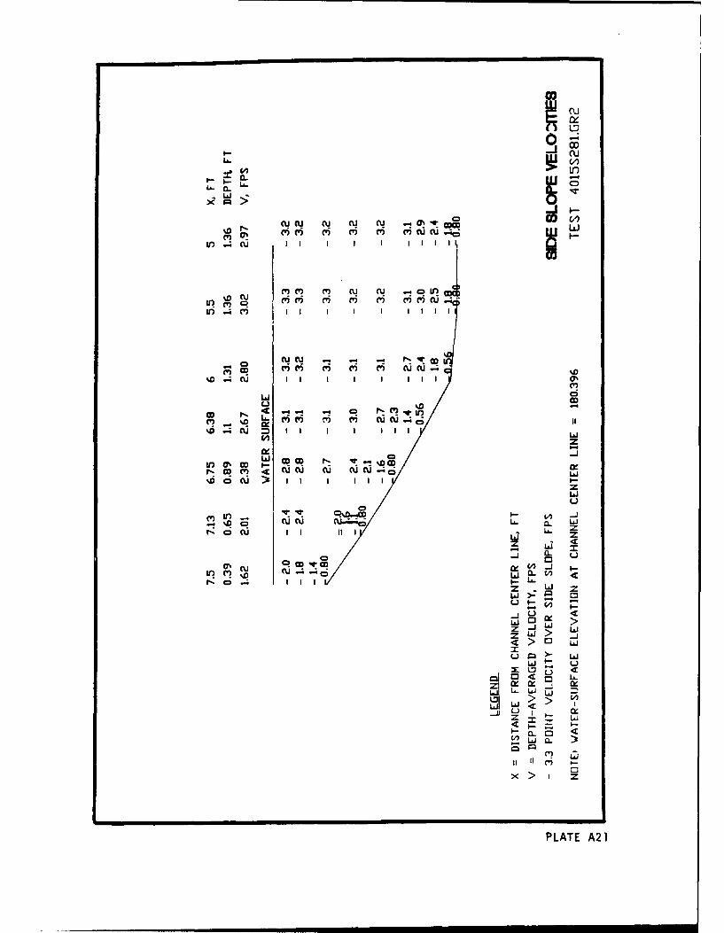
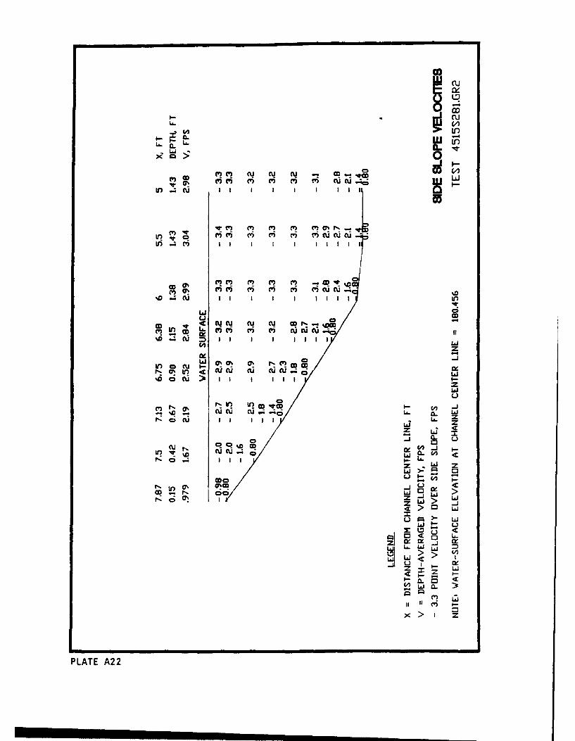
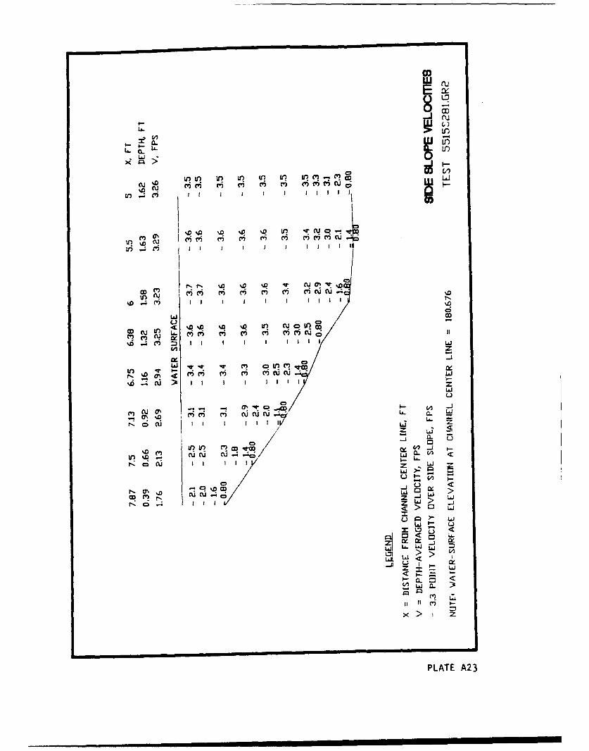
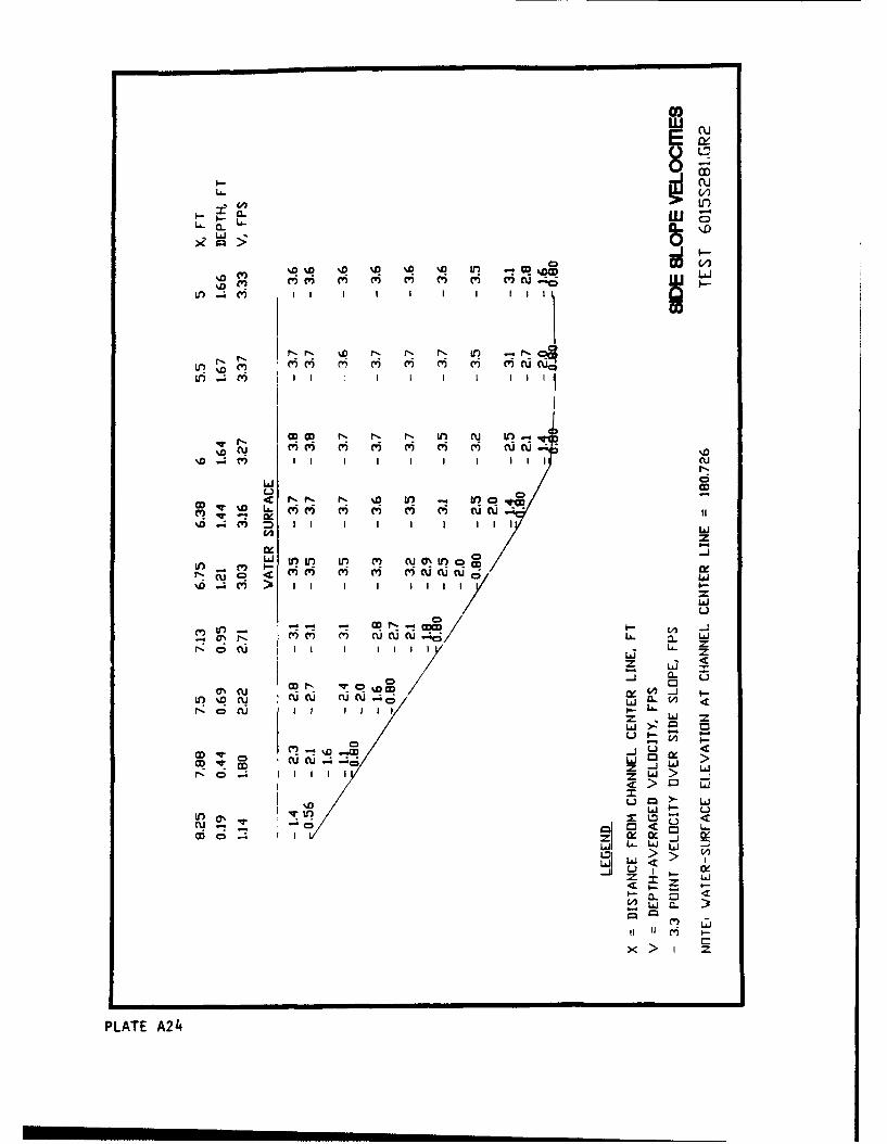
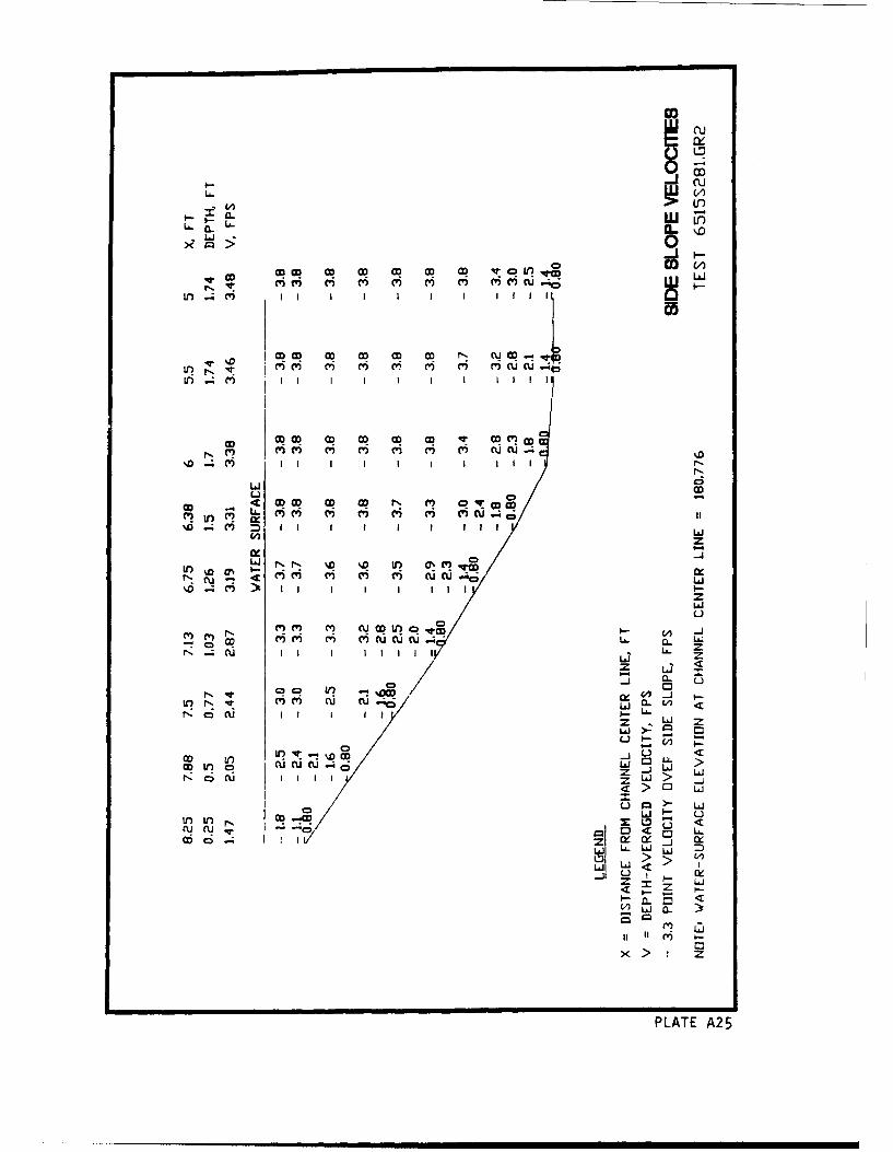
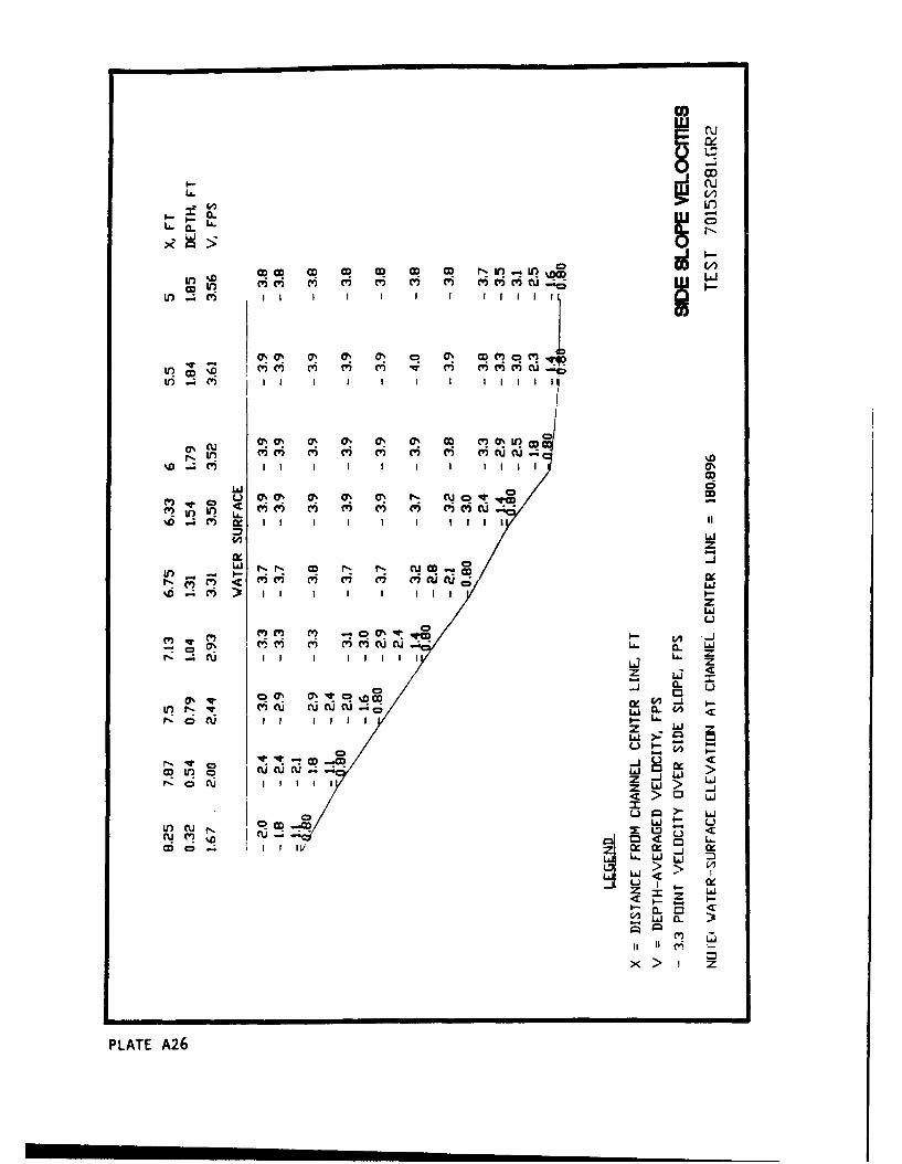
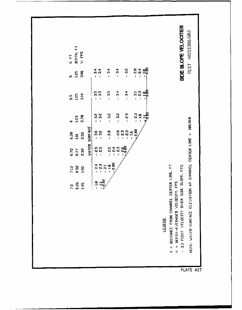
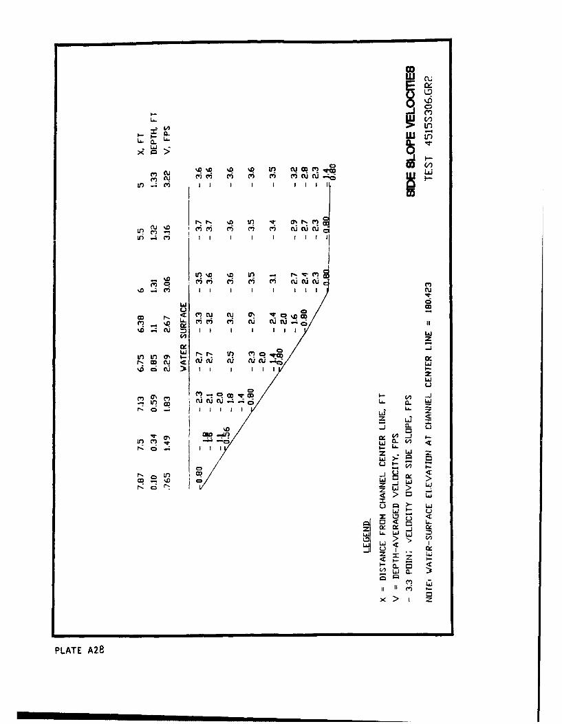
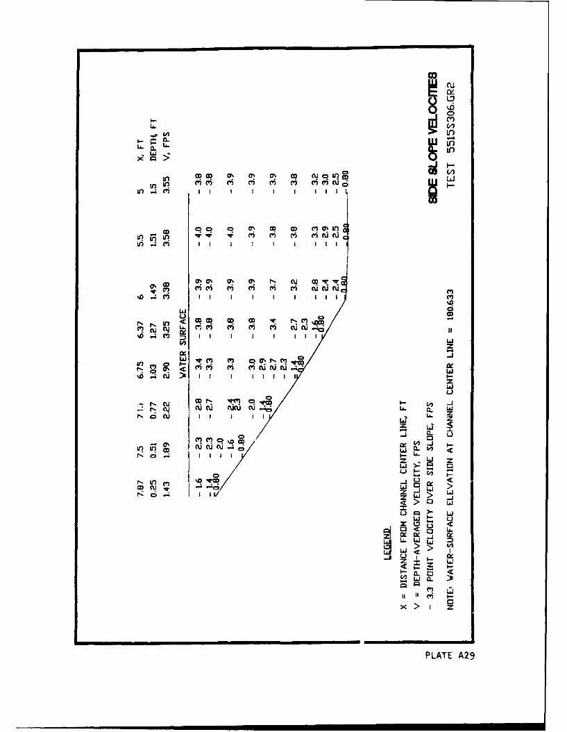
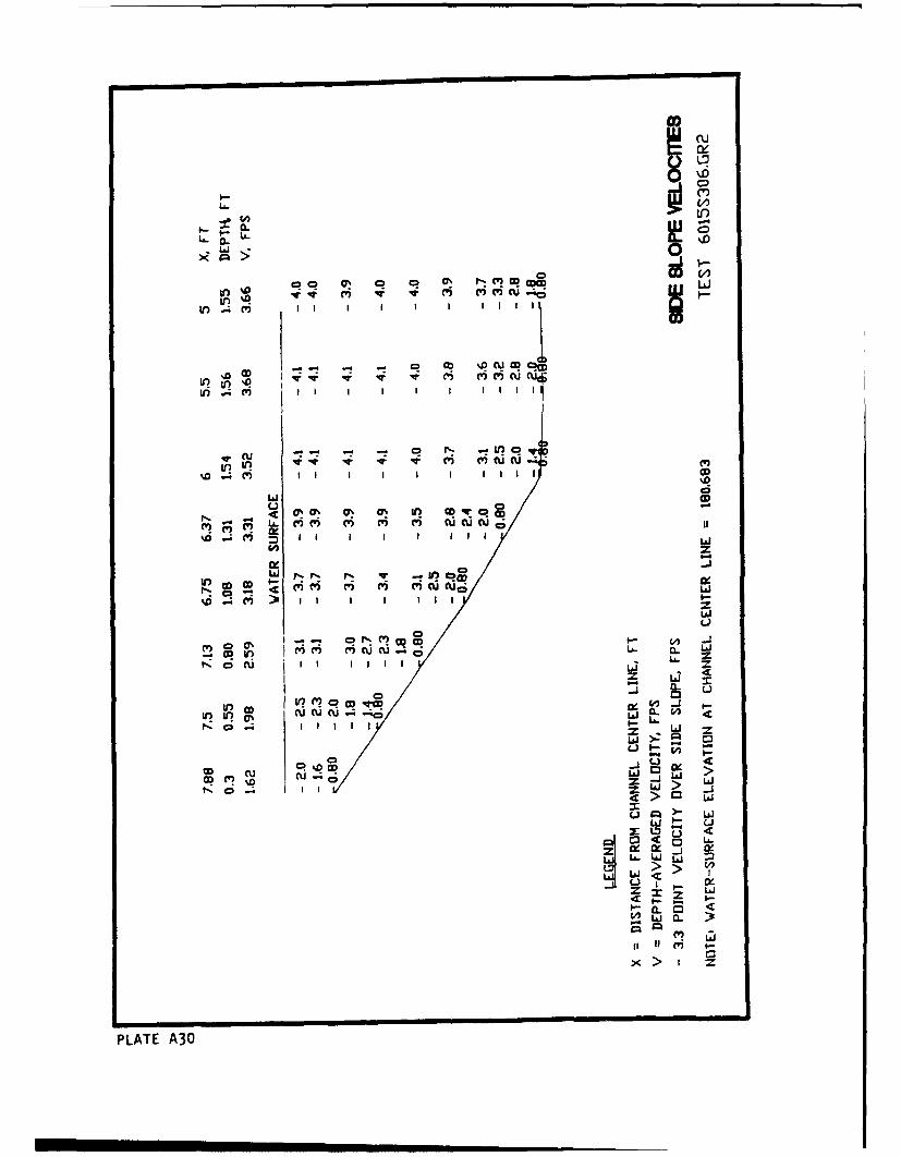
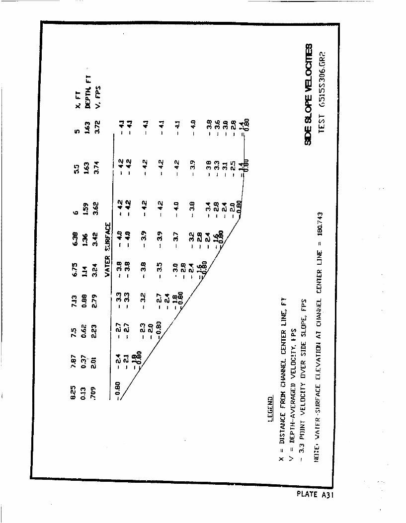
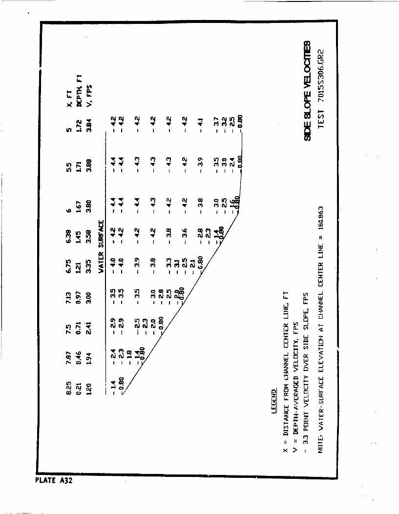
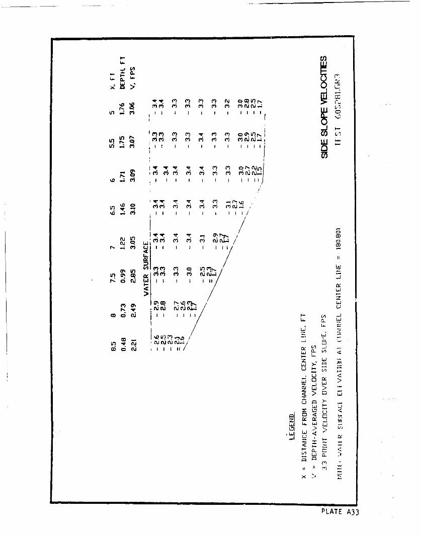
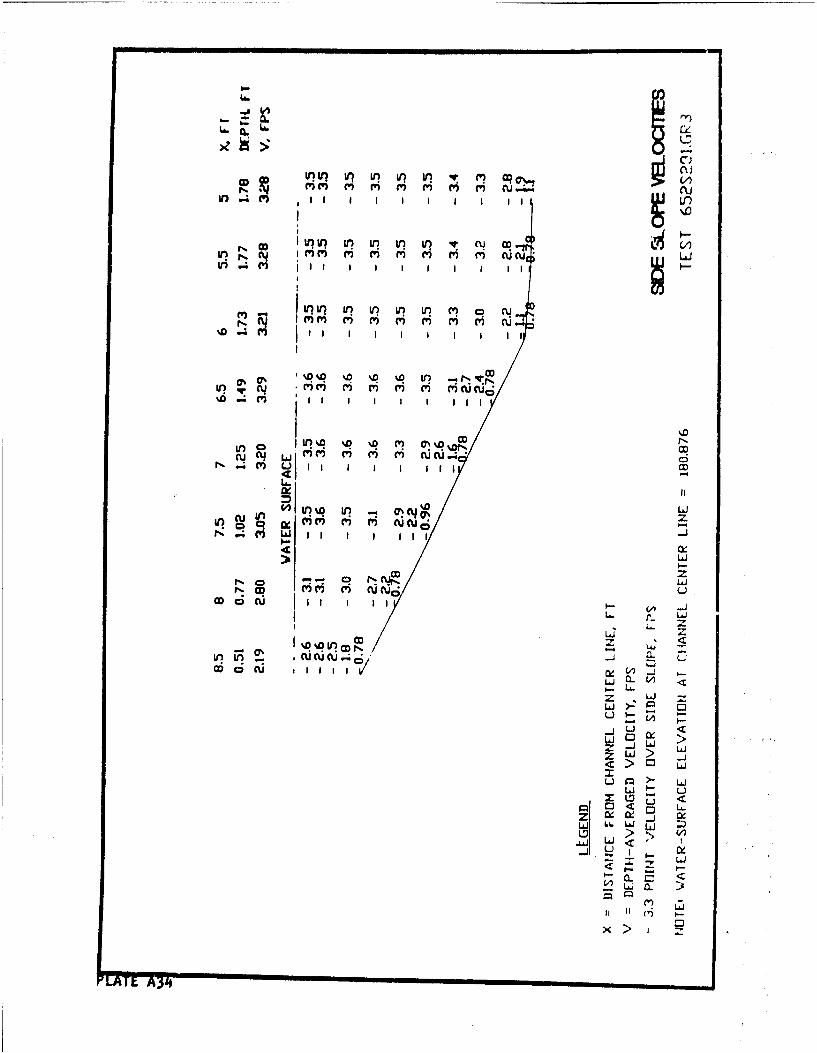
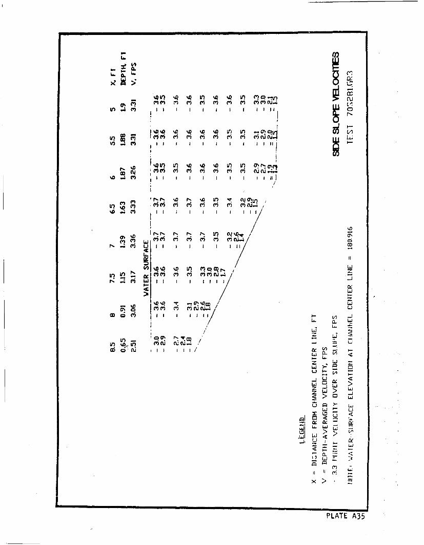
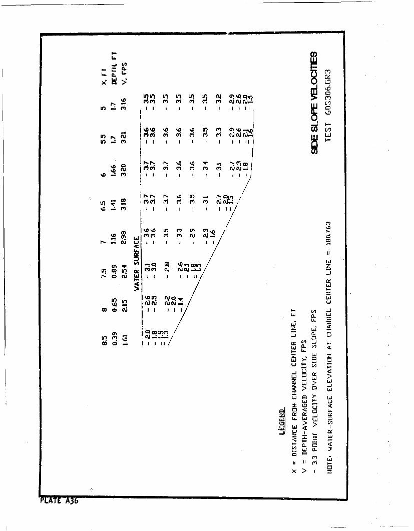
11. Stability testing of gradations 2 through 11 required documentation
of the velocities over the outer bank slope for discharges that resulted in
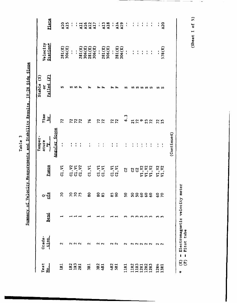
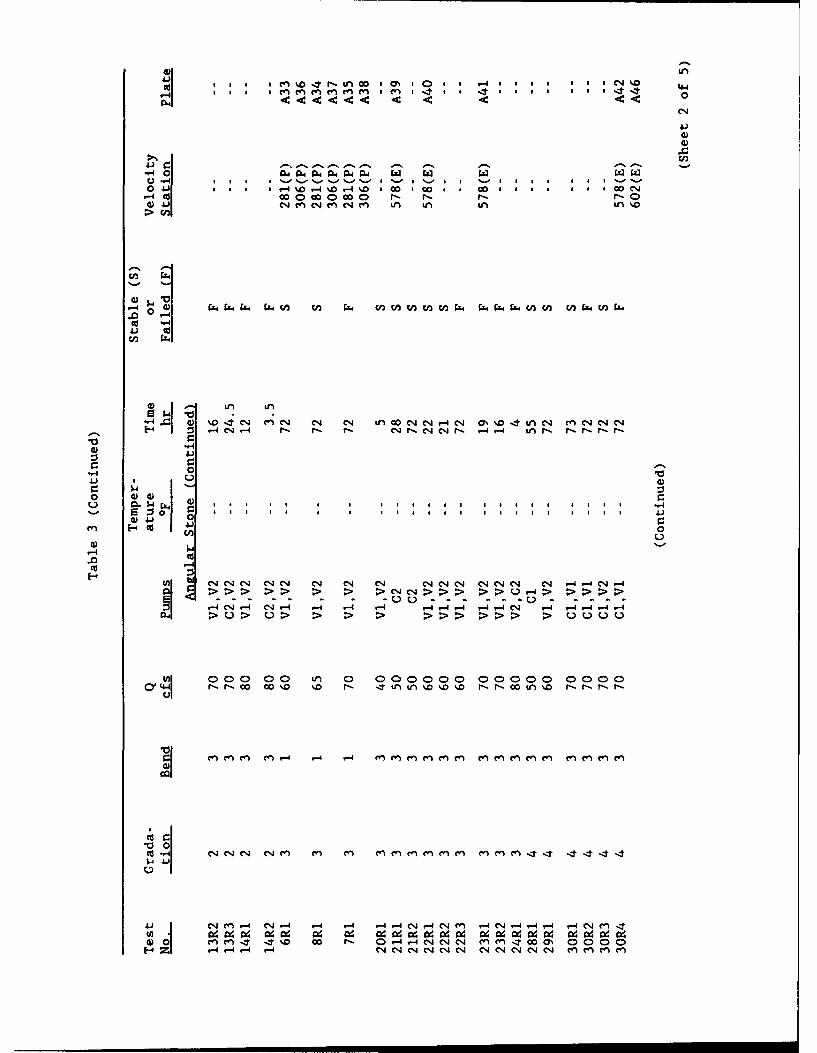
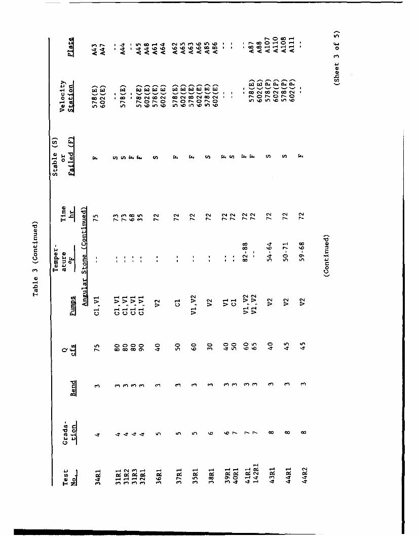
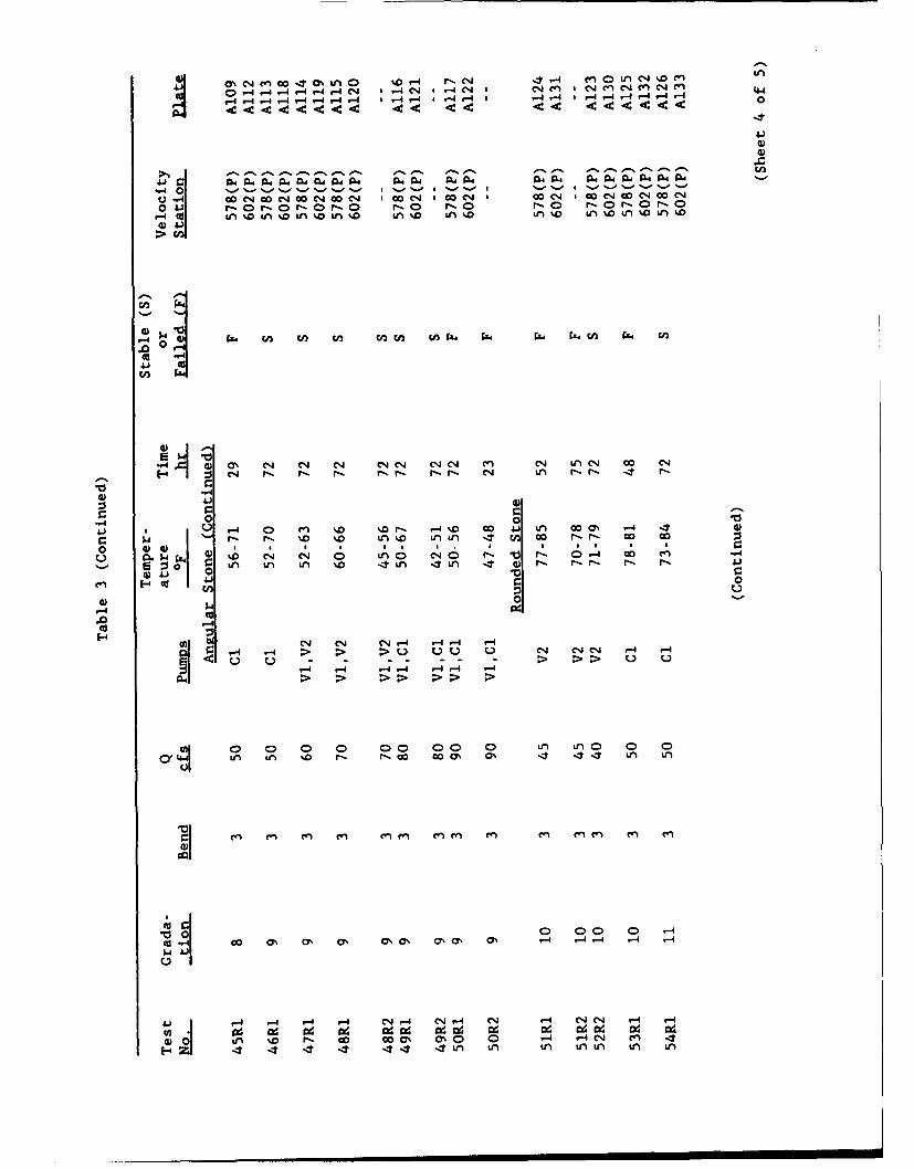
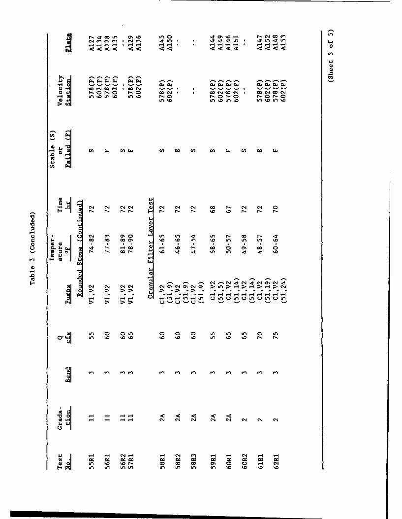
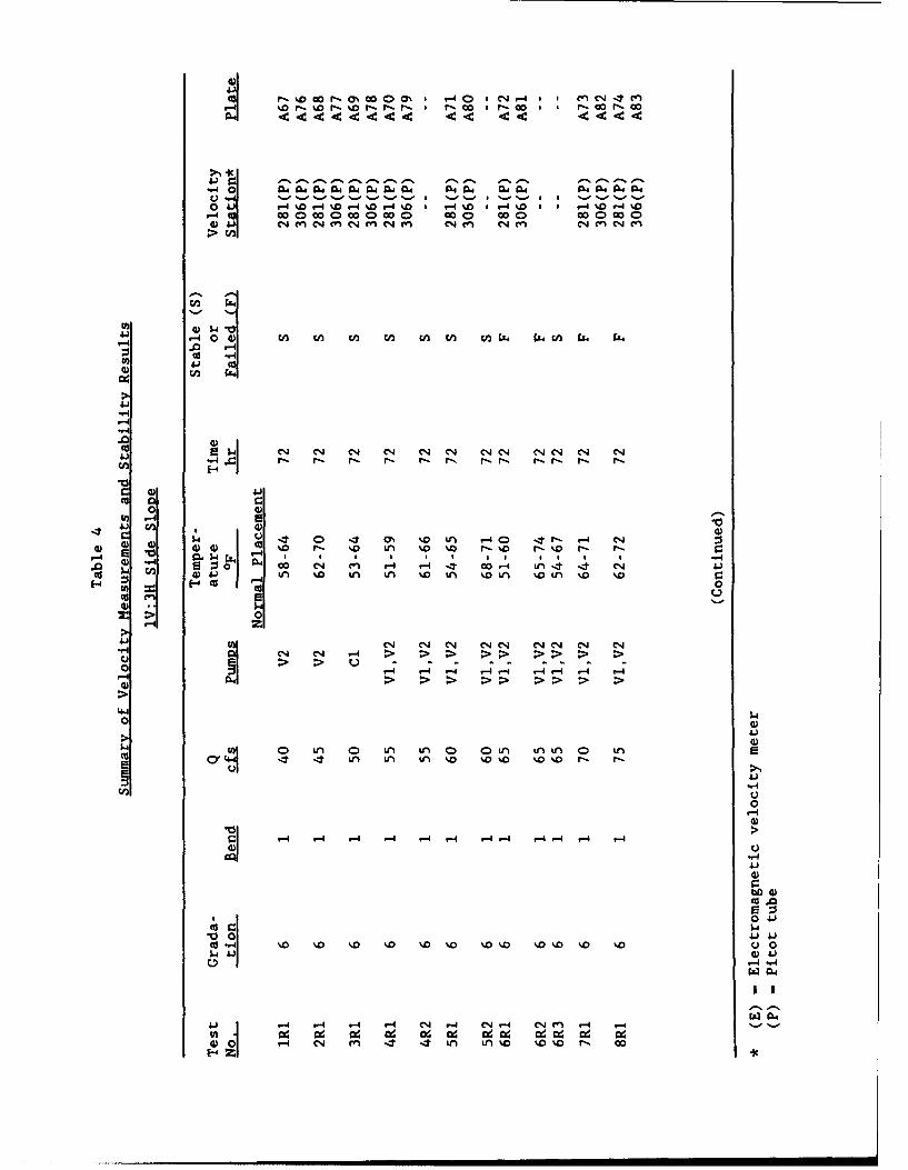
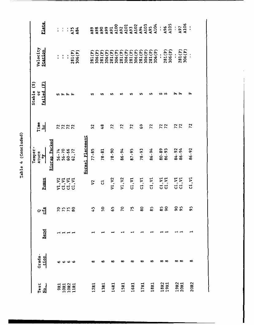
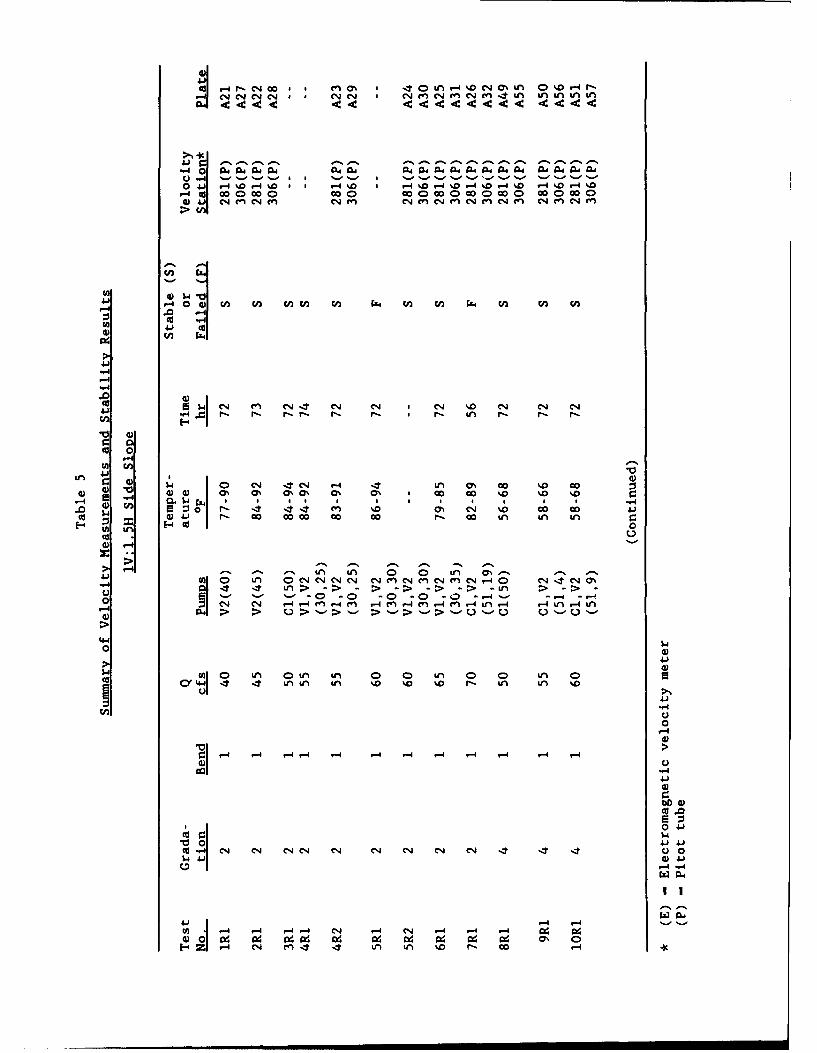
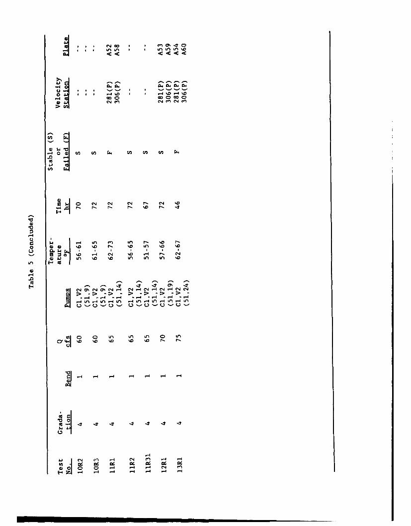
stable and failure conditions. Tables 3, 4, 5, and 6 summarize test condi-
tions for stability tests of gradations 2-11 and provide plate numbers in
Appendix A for the measured velocities for side slopes of lV:2H, IV:3H,
IV:I.SH, and bottom riprap, respectively. Test numbers in the side slope
velocity plots in Appendix A give the discharge first, then the cotangent of
the side slope, then the stone type (S for crushed stone, RS for rounded
stone), then the station where the velocities were measured, and finally the
gradation number. For example, test 502RS602.GlO was 50 cfs, lV:2H side
slope, rounded stone, sta 602, and gradation 10. Appendix B provides details
of observed rock movement and failure for each test.
11
PART IV: ANALYSIS AND RESULTS
Characteristic Particle Size
12. Maynord (1988), Abt et al. (1988), Ahmed (1987), and Anderson,
Paintal, and Davenport (1968) conducted riprap stability tests that showed
that for riprap gradations having the same D5 0 , the uniform gradations are
more stable than the nonuniform gradations. To make the nonuniform gradations
as stable as the uniform gradations requires a characteristic size less than
D50. Maynord (1988) found a characteristic size of D3 0 based on stability
tests of a range of gradations from uniform to nonuniform for thickness equal
to the maximum stone size. Einstein (1942), Schoklitsch (1962), California
Division of Highways (1970), Peterka (1958), and Shen and Lu (1983) also used
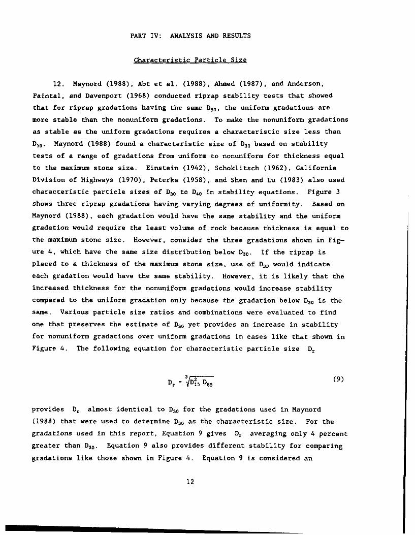
characteristic particle sizes of D3 0 to D40 in stability equations. Figure 3
shows three riprap gradations having varying degrees of uniformity. Based on
Maynord (1988), each gradation would have the same stability and the uniform
gradation would require the least volume of rock because thickness is equal to
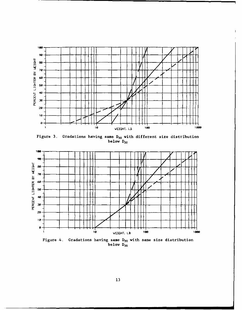
the maximum stone size. However, consider the three gradations shown in Fig-
ure 4, which have the same size distribution below D30 . If the riprap is
placed to a thickness of the maximum stone size, use of D30 would indicate
each gradation would have the same stability. However, it is likely that the
increased thickness for the nonuniform gradations would increase stability
compared to the uniform gradation only because the gradation below D3 0 is the
same. Various particle size ratios and combinations were evaluated to find
one that preserves the estimate of D3 0 yet provides an increase in stability
for nonuniform gradations over uniform gradations in cases like that shown in
Figure 4. The following equation for characteristic particle size Dr
Dr = 1D•5 D8 5 (9)
provides Dr almost identical to D30 for the gradations used in Maynord
(1988) that were used to determine D3 0 as the characteristic size. For the
gradations used in this report, Equation 9 gives D, averaging only 4 percent
greater than D30 . Equation 9 also provides different stability for comparing
gradations like those shown in Figure 4. Equation 9 is considered an
12
lee- - i / -
90-- -- - -- -
i e- _ _.,,-_
S70- -if
m,60-w
so-
20-4
10- -..- -01-t-
0. - - - I ,
hEH
1 10 WEIGHT. LB 100 100,
Figure 3. Gradations having same D30 with different size distributionbelow D30
16 -- - -l -- - ..
100-,••
80----
7a0-
70- - -" - - ,
ce 60-
so-
10 VEIG 00, L 1l0 10
450--LJ
e30w
20-
10-
0-1 10 WEIGHT. LB 100 188.
Figure 4. Gradations having same D30 with same size distributionbelow D30
13
improvement over the use of D30 as the characteristic size and should be used
if significantly different from D30 . D30 is used herein as the characteristic
size due to the similarity of Dr and D30.
Side Slope Angle Effects
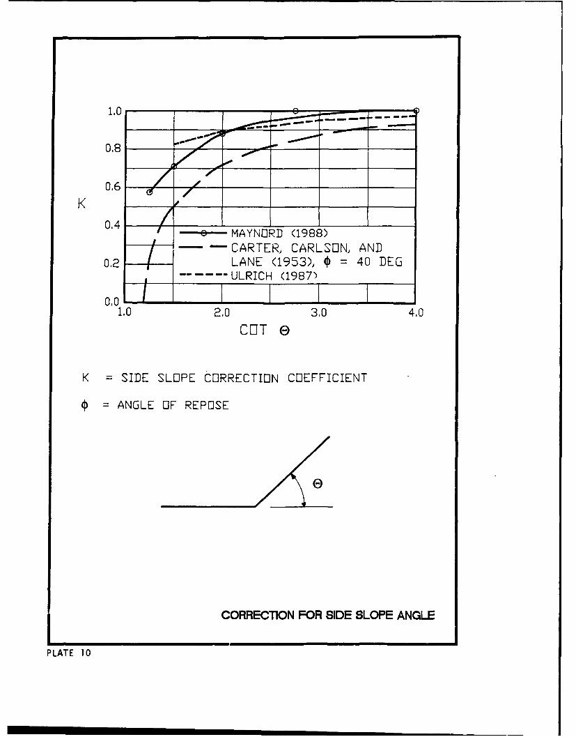
13. Systematic tests were reported in Maynord (1988) on the variation of
tractive force ratio K with side slope angle 8 , and results are shown in
Plate 10. Also shown is the tractive force approach given by Carter, Carlson,
and Lane (1953) and the relationship of Ulrich (1987). For side slopes in
channel bends, Brooks (1963) demonstrates the importance of secondary currents
on the K ratio. The angle of secondary currents remains poorly defined, and
their equation for K is not used herein. The experimentally derived values
for K from Maynord (1988) are in fair agreement with the results of Ulrich
(1987) and are adopted for this investigation. While revetments should not be
constructed near the angle of repose, this parameter is not the typical 40 deg
used by many (Plate 8); and repose angle will not be used in the side slope
analysis.
Flow Duration Effects on Riprap Stability
14. One of the difficult issues in riprap design is the influence of
time or flow duration on stability. One way to handle time is to treat riprap
design as a transport problem and define some maximum allowable transport
rate. This approach may be acceptable when there are multiple layers of mate-
rial but becomes questionable when a thin veneer of material is used, which is
frequently the case in riprap revetments. Another drawback to treating this
as a transport problem, as discussed in Part I, is the necessity for ease of
application. A further drawback is determining how the various hydrographs
over a given project life add together to form a total time for use in design.
Consequently, most riprap design procedures simply specify stability coeffi-
cients that are intended to apply to extremely long flow durations. Defining
flow conditions at which significant movement ceases has been termed practical
equilibrium. The following analysis will determine if a practical equilibrium
approach is justified for this study by conducting tests to evaluate the
influence of time on stability. Using the dimensional analysis given in
14
Maynord, Ruff, and Abt (1989) but adding time to the pertinent variables
results in
D f 7W V Vt (10)
The practical equilibrium concept can be used if a value of Vt/d can be found
above which time t has no significant effect on stability.
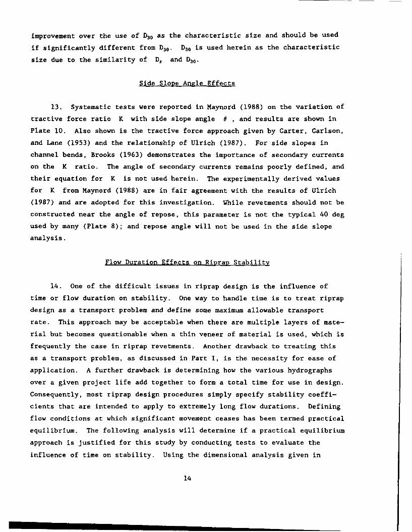
15. Testing was conducted with gradation 2 to test flow duration effects
with results as follows:
Q V d t
cfs frs -ft hr Result* Vt/d x 105
50 3.21 1.17 72 S 7.1
60 3.40 1.26 72 S 7.0
70 3.60 1.42 15 S 1.4
70 3.60 1.42 16 F 1.5
70 3.60 1.42 24.5 F 2.2
80 3.76 1.53 12 F 1.1
80 3.76 1.53 3.5 F 0.3
* S - stable; F - failure.
The velocity and depth are at a point 20 percent up the side slope from the
toe. These results, plotted in Figure 5, indicate a dependence of the failure
90
80
S• o FAILURE
~J70
60
0 STABLE
50 0 2 3 4 5 6 7 8
r20 t/d 2 0 x1O5
Figure 5. V20 t/d 20 x 105 versus discharge
15
discharge on the time parameter. As test duration goes up, failure discharge
goes down, which is the expected trend. For the gradation 2 tests, use of a
test duration shorter than 16 hr would not have permitted observing failure at
70 cfs. The dependance on Vt/d becomes minor for values of Vt/d greater
than 3-4 x l05 for the failure criteria used herein.
16. The CSU bottom riprap tests given in Maynord (1988) had an average
Vt/d of 2 x 10⁵ and resulted in an incipient failure coefficient of 0.30 for
bottom riprap in a straight channel. Bottom riprap tests (paragraph 24) con-
ducted in the straight channel portion of the RTF for Vt/d of 4 x l05 had an
incipient failure coefficient of 0.32, which may not be significantly differ-
ent from the CSU tests. Based on the gradation 2 tests and on the comparison
of bottom riprap in CSU and RTF testing, a minimum Vt/d of 4 x 10⁵ is pro-
posed for the failure criteria used herein and riprap thickness of 1D10 0 . At
Vt/d > 4 x 10⁵, time plays a minor role in determining failure. All stability
tests were conducted either until failure or for 72 hr, which resulted in
Vt/d of 4-7 x l05.
17. A question that must be answered is are there a significant number
of prototype installations having Vt/d < 4 x l05 that would benefit from a
design procedure that would reduce the rock size for short-duration flows?
Consider a rather flashy stream having a design velocity of 10 fps and a
design depth of 15 ft that occurs for one day per year over a design life of
25 years. The resulting Vt/d - 1.4 x 10⁶ demonstrates that even rather
flashy streams have total time parameters (Vt/d) greater than the limit
(4 x 10⁵) determined for minor time dependance.
Characteristic Velocity for Side Slopes
18. In developing a velocity-based design procedure, it is not suffi-
cient to use a side slope velocity or bank velocity unless a fixed location is
specified. This is because the velocity varies significantly with distance
from the waterline. In the initial development of the velocity-based design
procedure (Maynord 1988; Maynord, Ruff, and Abt 1989), a characteristic veloc-
ity of the depth-averaged velocity over the toe of the slope was used in the
design of side slope riprap. For straight channels, lV:2H side slope
(K - 0.88), and riprap thickness of 1D 100 , Equation 8 for incipient failure
for data presented in Maynord (1988) becomes
16
D30= .0 .21 125 V (11)
based on depth-averaged velocity and depth over the toe of the slope. Since
the coefficient in Equation 11 is less than the coefficient for bottom riprap
in straight channels, it is apparent that the velocity and depth over the toe
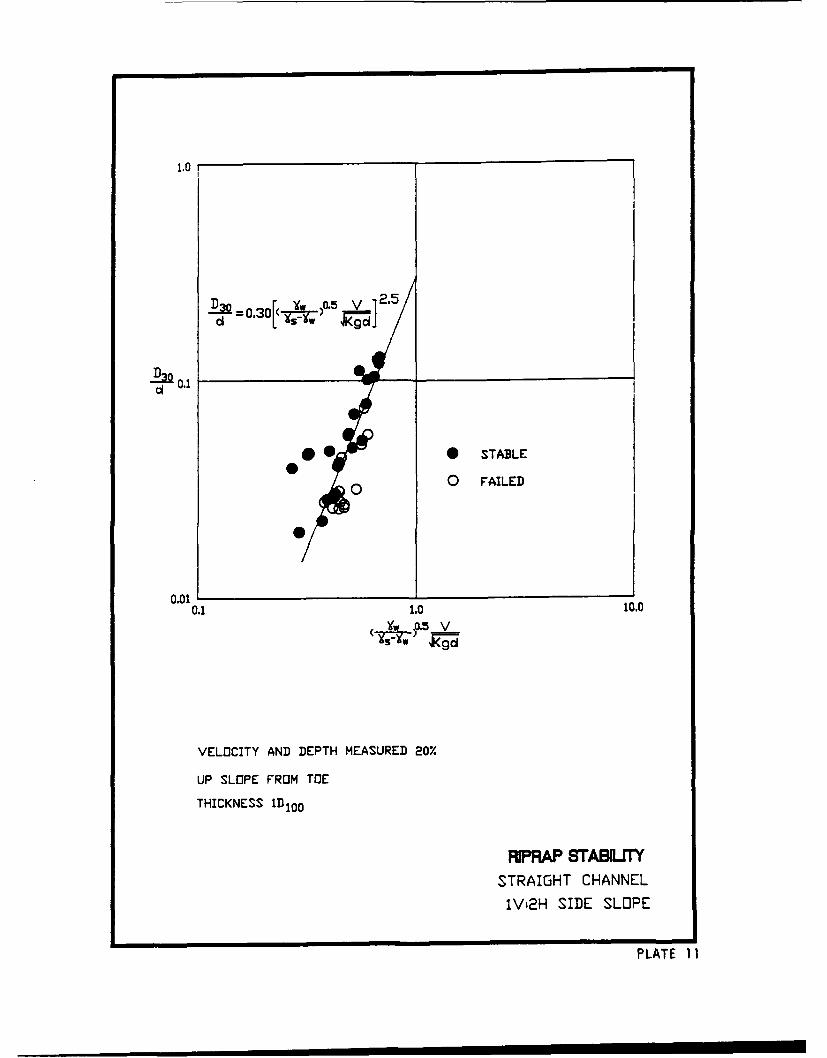
are not characteristic of the side slope in straight channels. Using the CSU
lV:2H side slope velocity and riprap stability data (Tables 7 and 8 and
Plate 11), a characteristic velocity and depth were found at 20 percent up the
slope from the toe that resulted in a coefficient of 0.30 in Equation 8.
Looking back at the straight channel shear distribution studies referenced in
Chow (1959), the maximum shear on the side slope occurred 20-30 percent up
from the toe for a side slope of IV:I.5H. Failures in the straight channel
tests at CSU were up on the side slopes and consistent with the location of
maximum shear given in Chow (1959). Comparing a point on the side slope
20 percent up the slope from the toe, the depth-averaged velocity in the CSU
straight channel over the 20 percent point is about 85 percent of the depth-
averaged velocity over the toe of the slope for a IV:2H side slope. In the
bends of the RTF, the depth-averaged velocity over the 20 percent point is
about 100 percent of the depth-averaged velocity over the toe of the slope.
Thus, the velocity distribution over the side slope is significantly different
in straight and curved channels. Failures in the RTF channel bends were
between 20 and 50 percent of the slope distance from the toe as described in
Appendix B. These factors lead to the conclusion that conditions at the toe
are not representative of the critical area of the channel side slope for both
straight and curved channels. The velocity and depth at 20 percent up the
slope from the toe are adopted as the characteristic values for both straight
and curved channels.
Rinrap Size in Channel Bends
19. Stability tests were conducted in bendways I and 3 for -id- slopes
of IV:2H, IV:3H, and IV:I.5H. Results are evaluated in the following para-
graphs using Equation 8 with K values from Maynord (1988) shown in Plate 10
17
and depth-averaged velocity and depth at a point 20 percent up the slope from
the toe.
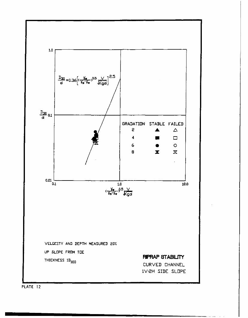
20. From channel bends 1 and 3 in the RTF, a lV:2H side slope (K - 0.88
in Equation 8), and riprap thickness of 1D 100 , the stability coefficient C
in Equation 8 for incipient failure is 0.36 using depth-averaged velocity and
depth at a point 20 percent up the slope from the toe. Equation 8 with
C - 0.36 is plotted in Plate 12 with stability data from gradations 2, 4, 6,
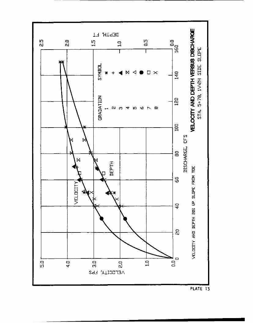
and 8 (Table 9). The measured velocities and depths shown in Appendix A were
used to develop a rating curve for velocity and depth at sta 5+78 in bend 3.
This rating curve (Plate 13) was used to determine velocity and depth for two
of the stability tests in which measurements were not conducted. Most of the
failures and the highest velocities were found at sta 3+06 and 5+78 in bends 1
and 3, respectively.
21. From channel bend 1 in the RTF, a lV:3H side slope (K - 0.98), and
ripL.p thickness of 1D 100 , stability tests were conducted for gradations 6
and 8. Results are shown in Table 10. Gradation 6 resulted in a stability
coefficient C of 0.36 to 0.37, which is consistent with IV:2H results using
Equation 8. Gradation 8 resulted in a stability coefficient of about 0.26,
which is considerably less than gradation 6 and results from the IV:2H side
slope tests. Past experience with stability tests have shown that uniform
ripraps such as gradations 2, 3, and 6 give consistent results. Highly non-
uniform ripraps like gradation 8 often give significant variation in the
results. Although it was not apparent when inspecting the test channel, there
may have been an excess of large particles at the critical point in the first
bend or simply a lack of size segregation in the critical areas. Highly non-
uniform ripraps have a significant capacity to "heal" themselves due to
upslope material moving into locally weak areas. Wittler and Abt (1990)
report that uniform and nonuniform ripraps fail in different ways. Uniform
ripraps tend to fail without a lot of prior movement of particles whereas
nonuniform ripraps tend to fail only after a significant amount of particle
movement or rearrangement.
22. From channel bend 1 in the RTF, a IV:I.5H side slope (K - 0.72), and
riprap thickness of ID1 00 , stability tests were conducted for gradations 2
and 4. Results are shown in Table 11. Gradation 2 resulted in a stability
coefficient in the range of 0.35 to 0.38, which is consistent with the results
from the lV:2H side slope and gradation 6 on the IV:3H side slope.
18
Gradation 4 resulted in a stability coefficient of 0.29 to 0.32. Gradation 4,
like gradation 8, is a nonuniform gradation, which had a significant amount of
movement prior to failure.
23. The difference between coefficients for riprap in a straight channel
(C - 0.30) and bend riprap (C - 0.36) is likely due to the secondary currents
present in the channel bend that alter the velocity distribution. The secon-
dary currents move the higher velocities near the channel boundary (Meckel
1978) and/or cause the resultant drag force to be skewed down the side slope
(Brooks 1963). The change in velocity profile was evident in profiles mea-
sured in bendway 1 with the lV:3H side slope. Velocity profiles were deter-
mined normal to the side slope at a point 20 percent up the side slope from
the toe at sta 2+81 and 3+06. Results are compared to straight channel flume
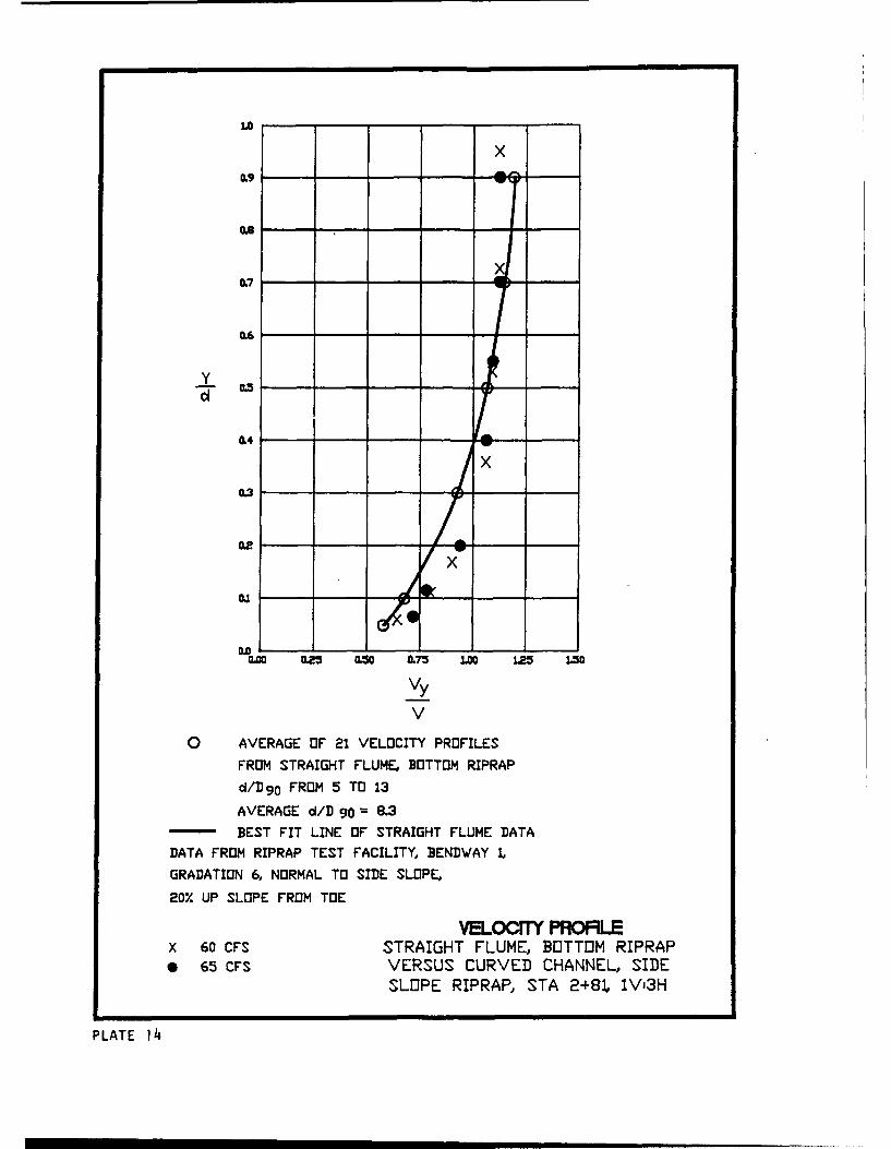
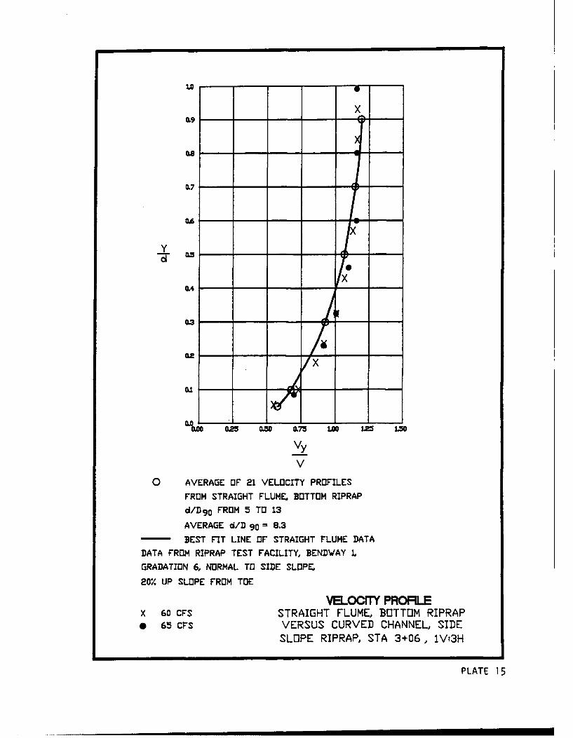
velocity profiles in Plates 14 and 15. Vy is the velocity at distance y
above the bottom. The increased velocities at the channel bottom are particu-
larly evident at sta 2+81. The magnitude of the secondary currents is primar-
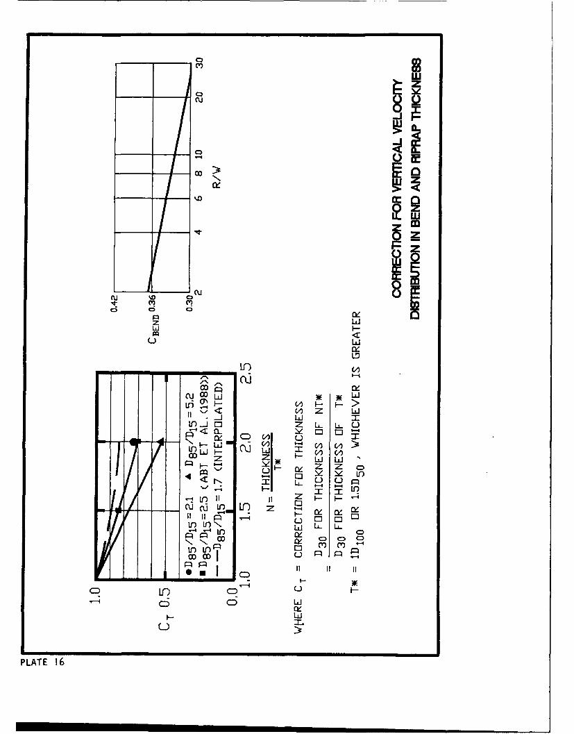
ily dependant on the degree of curvature, which is often described by the
ratio of center-line radius to channel width. Plate 16 presents a method for
varying the stability coefficient in Equation 8 as a function of R/W to
account for the change in velocity profile normal to the boundary. R is the
center-line radius of the bend and W is the water-surface width. Plate 16
is supported by RTF results for R/W - 2.5 having C - 0.36 and Maynord
(1988) results for straight channels (R/W - large) having C - 0.30 . What is
missing are data at various R/W to define the value of R/W at which a
channel is essentially straight. A conservative value of R/W - 25 was
chosen as the breakpoint for no curvature effect on the velocity profile.
This approach assumes fully developed bend flow since bend angle is not
included in the analysis.
Bottom RiDrap Tests
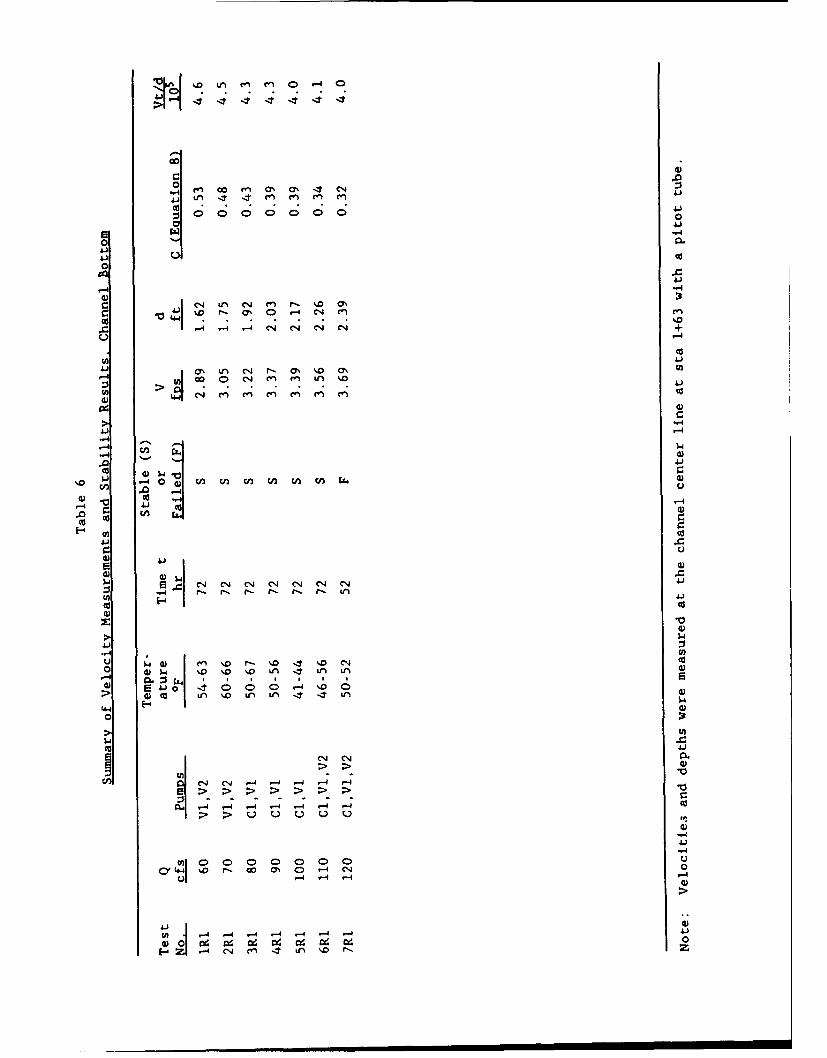
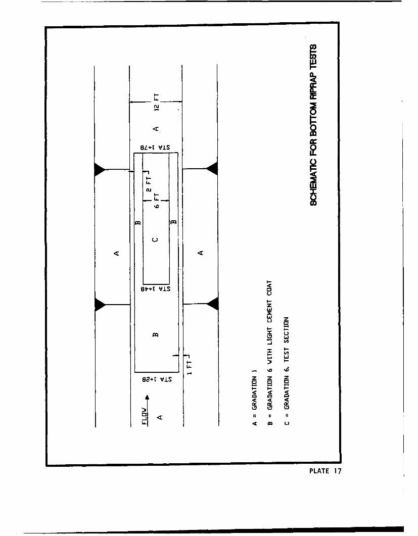
24. Bottom riprap tests were conducted in the straight reach upstream of
bendway 1 as shown in Plate 17. These tests were conducted to obtain data to
compare to the CSU straight flume data used in Maynord (1988) and to obtain
data regarding run time effects on riprap stability. Test results are shown
in Table 6. Failure occurred at a stability coefficient in Equation 8 of
C - 0.32
19
Riprap Thickness Effects
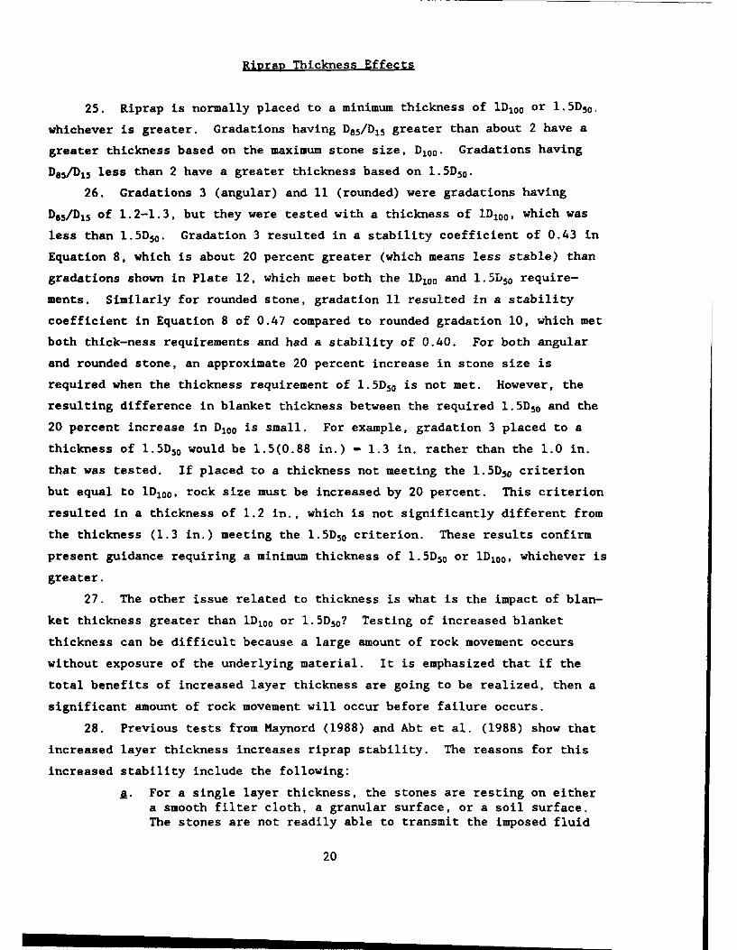
25. Riprap is normally placed to a minimum thickness of 1D10 0 or 1.5D50 ,
whichever is greater. Gradations having D85/DI5 greater than about 2 have a
greater thickness based on the maximum stone size, D10 0 . Gradations having
De6 /D15 less than 2 have a greater thickness based on 1.5D50 .
26. Gradations 3 (angular) and 11 (rounded) were gradations having
Doi/D, 5 of 1.2-1.3, but they were tested with a thickness of iD100 , which was
less than 1.5D50 . Gradation 3 resulted in a stability coefficient of 0.43 in
Equation 8, which is about 20 percent greater (which means less stable) than
gradations shown in Plate 12, which meet both the 1D100 and 1.5D50 require-
ments. Similarly for rounded stone, gradation 11 resulted in a stability
coefficient in Equation 8 of 0.47 compared to rounded gradation 10, which met
both thick-ness requirements and had a stability of 0.40. For both angular
and rounded stone, an approximate 20 percent increase in stone size is
required when the thickness requirement of 1.5D50 is not met. However, the
resulting difference in blanket thickness between the required 1.5D50 and the
20 percent increase in D100 is small. For example, gradation 3 placed to a
thickness of 1.5D50 would be 1.5(0.88 in.) - 1.3 in. rather than the 1.0 in.
that was tested. If placed to a thickness not meeting the 1.5D50 criterion
but equal to 1D100, rock size must be increased by 20 percent. This criterion
resulted in a thickness of 1.2 in., which is not significantly different from
the thickness (1.3 in.) meeting the 1.5D50 criterion. These results confirm
present guidance requiring a minimum thickness of 1.5D50 or 1D 100 , whichever is
greater.
27. The other issue related to thickness is what is the impact of blan-
ket thickness greater than ID 100 or 1.5D50? Testing of increased blanket
thickness can be difficult because a large amount of rock movement occurs
without exposure of the underlying material. It is emphasized that if the
total benefits of increased layer thickness are going to be realized, then a
significant amount of rock movement will occur before failure occurs.
28. Previous tests from Maynord (1988) and Abt et al. (1988) show that
increased layer thickness increases riprap stability. The reasons for this
increased stability include the following:
•. For a single layer thickness, the stones are resting on eithera smooth filter cloth, a granular surface, or a soil surface.The stones are not readily able to transmit the imposed fluid
20
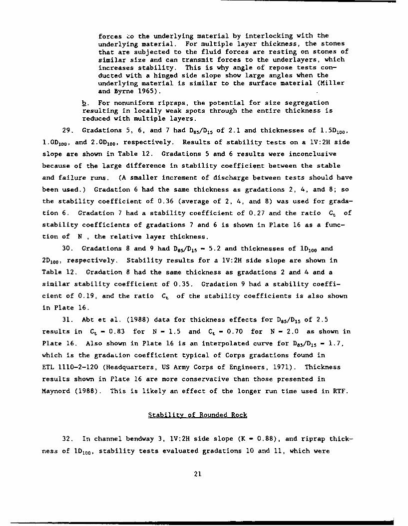
forces 9o the underlying material by interlocking with theunderlying material. For multiple layer thickness, the stonesthat are subjected to the fluid forces are resting on stones ofsimilar size and can transmit forces to the underlayers, whichincreases stability. This is why angle of repose tests con-ducted with a hinged side slope show large angles when theunderlying material is similar to the surface material (Millerand Byrne 1965).
k. For nonuniform ripraps, the potential for size segregationresulting in locally weak spots through the entire thickness isreduced with multiple layers.
29. Gradations 5, 6, and 7 had D85/D 15 of 2.1 and thicknesses of 1.5D1 00 ,
1.0D1 0 0 , and 2.OD200, respectively. Results of stability tests on a lV:2H side
slope are shown in Table 12. Gradations 5 and 6 results were inconclusive
because of the large difference in stability coefficient between the stable
and failure runs. (A smaller increment of discharge between tests should have
been used.) Gradation 6 had the same thickness as gradations 2, 4, and 8; so
the stability coefficient of 0.36 (average of 2, 4, and 8) was used for grada-
tion 6. Gradation 7 had a stability coefficient of 0.27 and the ratio Ct of
stability coefficients of gradations 7 and 6 is shown in Plate 16 as a func-
tion of N , the relative layer thickness.
30. Gradations 8 and 9 had D85/D 1 5 - 5.2 and thicknesses of 1D100 and2 Di00, respectively. Stability results for a IV:2H side slope are shown in
Table 12. Gradation 8 had the same thickness as gradations 2 and 4 and a
similar stability coefficient of 0.35. Gradation 9 had a stability coeffi-
cient of 0.19, and the ratio Ct of the stability coefficients is also shown
in Plate 16.
31. Abt et al. (1988) data for thickness effects for D8 5/D 1 5 of 2.5
results in Ct - 0.83 for N - 1.5 and Ct - 0.70 for N - 2.0 as shown in
Plate 16. Also shown in Plate 16 is an interpolated curve for D85 /D 1 5 - 1.7,
which is the gradaLion coefficient typical of Corps gradations found in
ETL 1110-2-120 (Headquarters, US Army Corps of Engineers, 1971). Thickness
results shown in Plate 16 are more conservative than those presented in
Maynord (1988). This is likely an effect of the longer run time used in RTF.
Stability of Rounded Rock
32. In channel bendway 3, lV:2H side slope (K - 0.88), and riprap thick-
ness of 1D 10 0 , stability tests evaluated gradations 10 and 11, which were
21
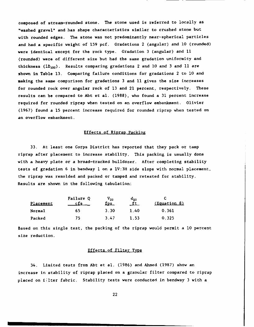
composed of stream-rounded stone. The stone used is referred to locally as
"washed gravel" and has shape characteristics similar to crushed stone but
with rounded edges. The stone was not predominantly near-spherical particles
and had a specific weight of 159 pcf. Gradations 2 (angular) and 10 (rounded)
were identical except for the rock type. Gradation 3 (angular) and 11
(rounded) were of different size but had the same gradation uniformity and
thickness (1D 1 0 0 ). Results comparing gradations 2 and 10 and 3 and 11 are
shown in Table 13. Comparing failure conditions for gradations 2 to 10 and
making the same comparison for gradations 3 and 11 gives the size increases
for rounded rock over angular rock of 13 and 21 percent, respectively. These
results can be compared to Abt et al. (1988), who found a 31 percent increase
required for rounded riprap when tested on an overflow embankment. Olivier
(1967) found a 15 percent increase required for rounded riprap when tested on
an overflow embankment.
Effects of Riprap Packing
33. At least one Corps District has reported that they pack or tamp
riprap after placement to increase stability. This packing is usually done
with a heavy plate or a broad-tracked bulldozer. After completing stability
tests of gradation 6 in bendway 1 on a lV:31 side slope with normal placement,
the riprap was remolded and packed or tamped and retested for stability.
Results are shown in the following tabulation:
Failure Q V20 d 20 CPlacement cfs fDS ft (Equation 8)
Normal 65 3.30 1.40 0.361
Packed 75 3.47 1.53 0.325
Based on this single test, the packing of the riprap would permit a 10 percent
size reduction.
Effects of Filter Type
34. Limited tests from Abt et al. (1986) and Ahmed (1987) show an
increase in stability of riprap placed on a granular filter compared to riprap
placed on LIter fabric. Stability tests were conducted in bendway 3 with a
22
granular filter placed beneath gradations 2 and 2A and on top of the existing
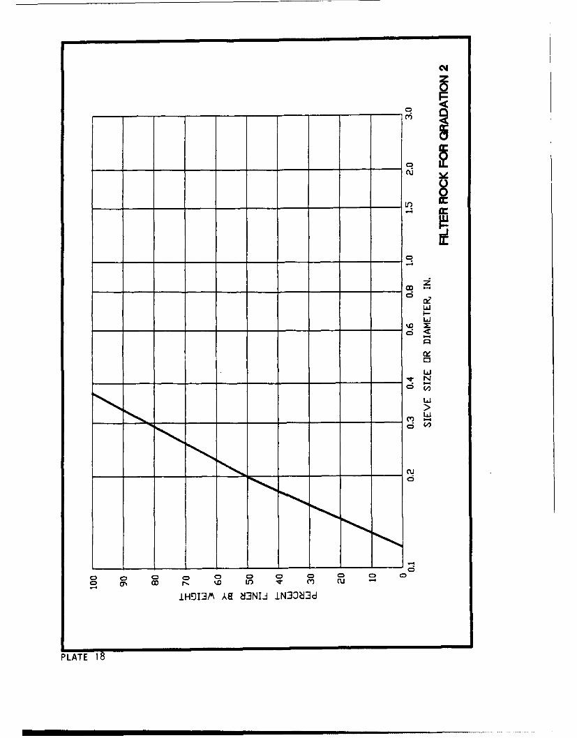
filter fabric used in all other tests. The gradation of the l-in.-thick-
granular filter is shown in Plate 18, and stability results are given in
Table 14. As with the packing tests, these filter effect results are based on
only a small number of tests (two), but results indicate about a 10 percent
reduction in stone size when a granular filter was used based on a stability
coefficient of 0.32-0.33.
23
PART V: SUMMARY AND CONCLUSION
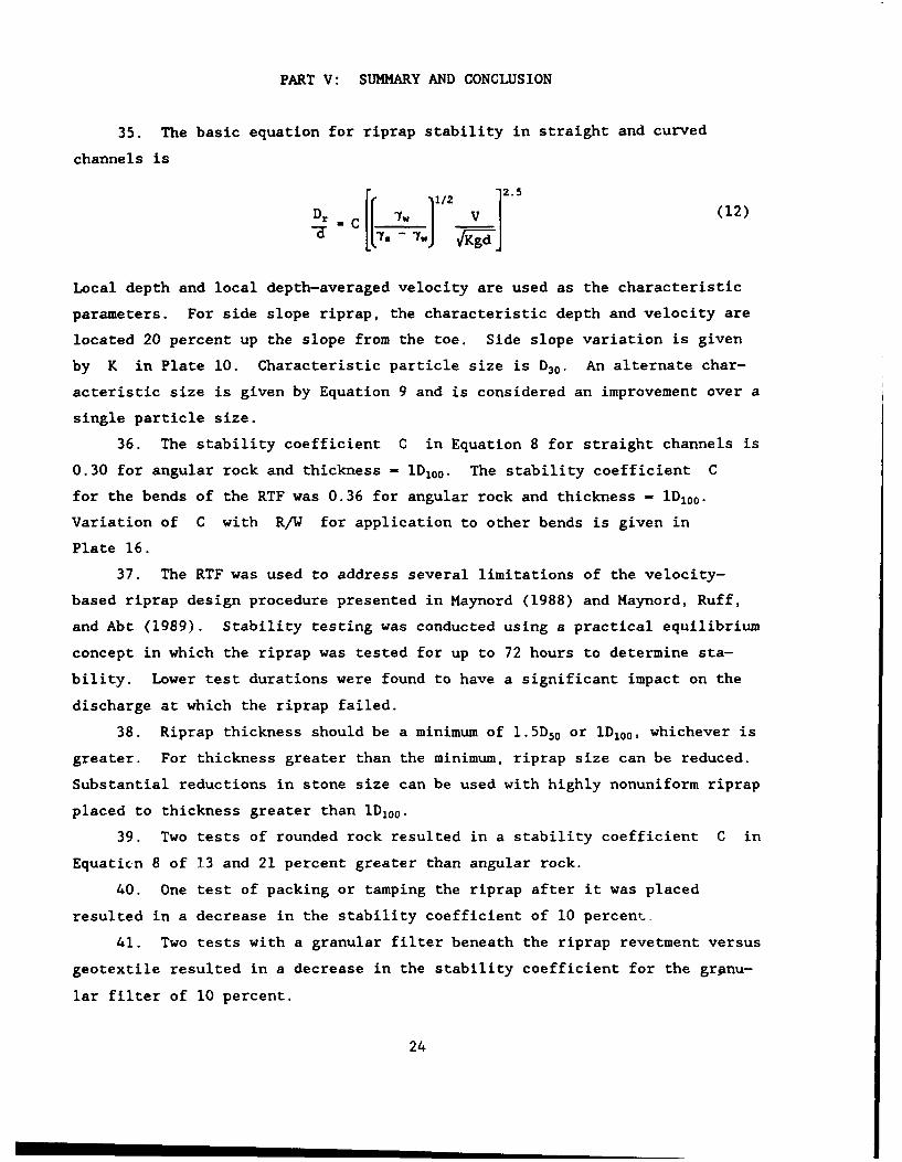
35. The basic equation for riprap stability in straight and curved
channels is
1/2 2.
D Clr ] (12)
Local depth and local depth-averaged velocity are used as the characteristic
parameters. For side slope riprap, the characteristic depth and velocity are
located 20 percent up the slope from the toe. Side slope variation is given
by K in Plate 10. Characteristic particle size is D3 0 . An alternate char-
acteristic size is given by Equation 9 and is considered an improvement over a
single particle size.
36. The stability coefficient C in Equation 8 for straight channels is
0.30 for angular rock and thickness - 1D10 0 . The stability coefficient C
for the bends of the RTF was 0.36 for angular rock and thickness - 1D10 0 .
Variation of C with R/W for application to other bends is given in
Plate 16.
37. The RTF was used to address several limitations of the velocity-
based riprap design procedure presented in Maynord (1988) and Maynord, Ruff,
and Abt (1989). Stability testing was conducted using a practical equilibrium
concept in which the riprap was tested for up to 72 hours to determine sta-
bility. Lower test durations were found to have a significant impact on the
discharge at which the riprap failed.
38. Riprap thickness should be a minimum of 1.5D50 or 1D100 , whichever is
greater. For thickness greater than the minimum, riprap size can be reduced.
Substantial reductions in stone size can be used with highly nonuniform riprap
placed to thickness greater than 1D 100 .
39. Two tests of rounded rock resulted in a stability coefficient C in
Equaticn 8 of 13 and 21 percent greater than angular rock.
40. One test of packing or tamping the riprap after it was placed
resulted in a decrease in the stability coefficient of 10 percent.
41. Two tests with a granular filter beneath the riprap revetment versus
geotextile resulted in a decrease in the stability coefficient for the grAnu-
lar filter of 10 percent.
24
REFERENCES
Abt, S. R., Ruff, J. F., Khattak, M. S., Wittier, R. J., Shaikh, A., andNelson, J. D. 1986. "Environmental Assessment of Uranium RecoveryActivities-Riprap Testing, Phase I," CSU Report No. CER86-865RA-JFR-MSK-RJW-AS-JON24, Prepared by Colorado State University, Fort Collins, CO, for OakRidge National Laboratory, Oak Ridge, TN.
Abt, S. R., Wittier, R. J., Ruff, J. F., LaGrone, D. L., Khattak, M. S.,Nelson, J. D., and Hinkle, N. E. 1988. "Development of Riprap DesignCriteria by Riprap Testing in Flumes: Phase II," NUREG/CR-4651, ORNL/TM-10100/V2, Vol 2, Prepared by Colorado State University, Fort Collins, CO, andOak Ridge National Laboratory, Oak Ridge, TN, for Nuclear Regulatory Commis-sion, Washington, DC.
Ahmed, A. F. 1987. "Stability of Riprap Side Slopes in Open Channels," M. S.thesis, University of Southampton, United Kingdom.
Anderson, A. G., Paintal, A. S., and Davenport, J. T. 1968. "TentativeDesign Procedure for Riprap Lined Channels," Project Report No. 96,St. Anthony Falls Hydraulic Laboratory, University of Minnesota, Minneapolis,MN.
Brooks, N. H. 1963 (May). Discussion of "Boundary Shear Stresses in CurvedTrapezoidal Channels," by A. T. Ippen and P. A. Drinker, Journal of theHydraulics Division. Proceedings of the American Society of Civil Engineers.Vol 89, No. HY3, pp 327-333.
California Division of Highways. 1970. "Bank and Shore Protection inCalifornia Highway Practice," State of California, Department of Public Works,Sacramento, CA.
Carter, A. C., Carlson, E. J., and Lane, E. W. 1953. "Critical TractiveForces on Channel Side Slopes in Coarse, Non-cohesive Material," HydraulicLaboratory Report No. HYD-366, US Bureau of Reclamation, Denver, CO.
Chow, V. T. 1959. Open-Channel Hydraulics. McGraw-Hill, New York.
Einstein, H. A. 1942. "Formulas for the Transportation of Bed Load," Trans-actions. American Society of Civil Engineers, pp 107, 561-597.
Headquarters, US Army Corps of Engineers. 1971. "Additional Guidance forRiprap Channel Protection," ETL 1110-2-120, US Government Printing Office,Washington, DC.
Headquarters, US Army Corps of Engineers. 1991. "Hydraulic Design of FloodControl Channels," EM 1110-2-1601, US Government Printing Office, Washington,DC.
Maynord, S. T. 1988. "Stable Riprap Size for Open Channel Flows," TechnicalReport HL-88-4, US Army Engineer Waterways Experiment Station, Vicksburg, Ms.
Maynord, S. T., Ruff, J. F., and Abt, S. R. 1989 (July). "Riprap Design,"Journal of Hydraulic Engineering. American Society of Civil Engineers.Vol 115, No. 7, pp 937-949.
Meckel, H. 1978 (Oct). "Spiral Flow and Sediment Motion in River and ChannelBends," Wasserwirtschaft. Vol 68, No. 10, pp 287-294.
Miller, R. L., and Byrne, R. J. 1965. "The Angle of Repose of a Single Grain
25
on a Fixed Rough Bed," Prepared under Contract Nonr-2121(26) by the Universityof Chicago, Chicago, IL, for Office of Naval Research, Arlington, VA.
Neill, C. R. 1967. "Mean-velocity Criterion for Scour of Coarse Uniform Bed-Material," Proceedings. 12th Congress of the international Association forHydraulic Research. Colorado State University, Fort Collins, CO, Paper C6,Vol 3, pp C6.1-C6.9.
Olivier, H. 1967. "Through and Overflow Rockfill Dams - New Design Tech-niques," Proceedings of the Institution of Civil Engineers. Vol 36, No. 7012,pp 433-471.
Permanent International Association of Navigation Congresses. 1987. "Guide-lines for the Design and Construction of Flexible Revetments IncorporatingGeotextiles for Inland Waterways," Report of Working Group 4 of the PermanentTechnical Committee 1, Supplement to Bulletin No. 57, Brussels, Belgium.
Peterka, A. J. 1958. "Hydraulic Design of Stilling Basins and Energy Dissi-pators," Engineering Monograph No. 25, US Bureau of Reclamation, Denver, CO.
Pilarczyk, K. W. 1990. "Stability Criteria for Revetments," Hydraulic Engi-neering: Proceedings of the 1990 National Conference. American Society ofCivil Engineers, 30 July-3 August 1990, San Diego, CA, Howard H. Chang andJoseph C. Hill, ed., New York, pp 245-250.
Schoklitsch, A. 1962. Handbuch des Wasserbaues. Springer-Verlag, Vienna.
Shen, H. W., and Lu, J. 1983. "Development and Prediction of Bed Armoring."Journal of Hydraulic Engineering. American Society of Civil Engineers,Vol 109, No. 4, pp 611-629.
Ulrich, T. 1987. "Stability of Rock Protection on Slopes," Journal ofHydraulic Engineering. American Society of Civil Engineers. Vol 113, No. HY7,pp 879-891.
Wittler, R. J., and Abt, S. R. 1990. "The Influence of Uniformity on RiprapStability," Hydraulic Engineering: Proceedings of the 1990 NationalConference. American Society of Civil Engineers, 30 July-3 August 1990, SanDiego, CA, Howard H. Chang and Joseph C. Hill, ed., New York, pp 251-256.
26
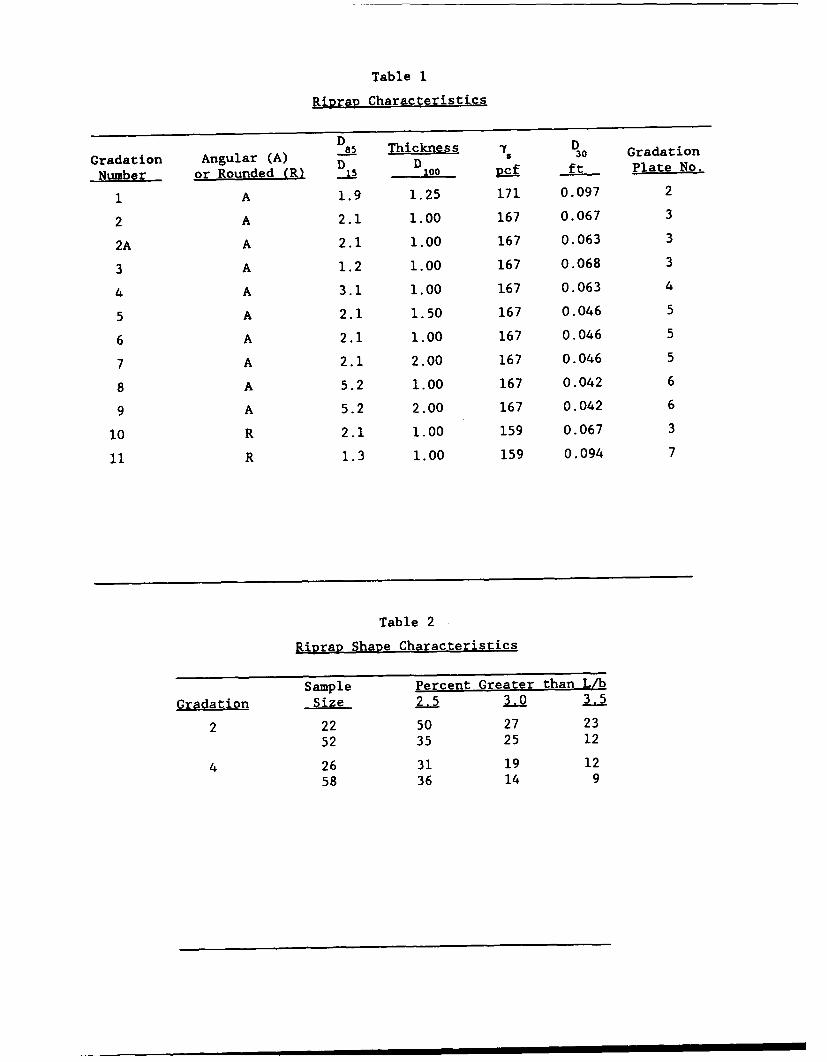
Table 1
RipraD Characteristics
D8_• Thickness Ds3 rdtoDD
Gradation Angular (A) D TiDkns Gradation
Number or Rounded (R) 15 100 Pat ft Plate No.
I A 1.9 1.25 171 0.097 2
2 A 2.1 1.00 167 0.067 3
2A A 2.1 1.00 167 0.063 3
3 A 1.2 1.00 167 0.068 3
4 A 3.1 1.00 167 0.063 4
5 A 2.1 1.50 167 0.046 5
6 A 2.1 1.00 167 0.046 5
7 A 2.1 2.00 167 0.046 5
8 A 5.2 1.00 167 0.042 6
9 A 5.2 2.00 167 0.042 6
10 R 2.1 1.00 159 0.067 3
11 R 1.3 1.00 159 0.094 7
Table 2
RiDrap Shape Characteristics
Sample Percent Greater than L/b
Gradation Size 2.5 3.0 3.5
2 22 50 27 2352 35 25 12
4 26 31 19 1258 36 14 9
Oil, - %0 C1 o 'r- en' *co 0% 44 aa 'P- "a a4 - r-4 r-4 ý4~ r4 a4 S4 I I I
0
v-4
4.)
00
04. 1 -4% -S I.D -4 %D -4% - ,DcS40 cooZ cocco ao0 ooZ
Oji en 04 M ~C14 n C4~f CJ04mn Ln
0
-4
'4)
'-4
0
041
10
2.1
E4 m'CN ' E-4 CdC. ~ eJ e' C ~ sCs bd'.
U)~
IA
004
r4- dc 0c I O OD 0 r- r-. r rl- 0041 04e 4Cb 4f Ltn LA Ln Ln%0
En 144
0 " A L
4 %0 -4C' M IC-4 C1J 04 Ln O tNC14 4C14 0 %D ILM C4 e fl14 C-4 CE-4 4 CS e.1-4 r- r- r-. CN JýeC-4 r-. -4 -4 Ln r-. tr- r-r--
ý4-41 W
C) E-4 CU 41 0
-4 -
E--Il CIJ 0J4 CN 04C%J C%4 14 04 C%4 CN CN e J (N(NCN (4 .- 4 -4 C14-4
m 000 00 LA 0 000000 00000 0000olI
N4~ M - J C4 -4 4 - 44 (C %Jr-4C-4M C-4 - -4 ý Cl4( M
4)0 m 4%0 co rý 0 -4( NN e4CI C r - f Mý*ODO 0000
00 r Ln
fn 0-U
0 r 4 L - f Dý 4 14
oJ-J
4(d r- 0 r- .r~r, r-.0r- 0r-% n D %0 U LA%.040 4J i W l %0 l %D LA %0 Ln -.0LA)
ý40 4) 44 En cnWlw c w W E
.0 ' -
.4 I ) LA C" 0L (N cok - (N (N 0'4 (N(" 04( ( N C'4 (N4
0 ~410
41 0 0 It -4 c 0)
C: 1-o %0 %O r-
en 00m
4)-
~ E-4tU -4-0ci~ U4 ý 4 - " 4C4
ý4 I a4-4
a-I a-d (N (N(NL) uN u- u' L) >- )> > N (N (
tn l Co0 0 0 CD C 0 0 f D r r
LA 00 00 0o 0o 0% 0 00D (n 0 D LA0
10o
41r- - a-4~ M O -4. LA4 04 -40 r4-4
V4 4 ý4 4~
4)0 1 4- 4 % - L 00 ON 0 r4 It c" 41 4
ChO~ A Ln 04 rý- C144,-4 M n ML-4 ý4 -4 - 4r4" 1- C 40 C4N M( " en ,N 4r CnC4M4
r4 r4 ý -4-4 ý ý4ý4 4 -4 4 - ý4 ý4 4ý4 4 ý r40
0I r-oCr-or - 0 f-O rý O r, o r-O0 r-O0r, 0Or- O
4 d L DLn ODL A'Q nD LA'%D w L%Q IJ% u .oW 'D LA'OA' %D~
.0 1rca -4I*
04 CN C- 04 C- C4 C-4 C14 M f W) 4N 00
00 1
'.4 4. 0 04. n c ON ý
In 00 r- r" *o c aa a%D C ' N (N4 0 LAO ( O i. r C)- C, -,4
:3 L LA) LA) %.0 4LA 4LA V 4 01 4) r"~ r ~ r" 4.
0) 0
-44
(Nj (N4 C-4 .4-4 -4 -4
U4 U_;- - > > >
0 0' 0 00 00 0 LA LAO0Cy44 LA LA rI- r c c ~0% 0% 4 LA LA
0 00 0-410' 0' 0 0'0 ON ON 1-4 ,-4 -4 .- 4 ,-4
-4 -4 (-4 4 C-4 (N -4 0 0(N( 14 ,-
ad 04 C0' 0'O 04 4e4N .
4 4 4 4 4 4Ln LA LA LML LA) LA
w 4 LM O%D LAO %0 V4 r C- 40 nLA
4-)
"4. 0 4 04040 9L. -%4 04 ____ 04CL '9u 40 000. C14 04 C-4 0. 0400.
-4j tOr- r-O %0N ' 1e4c0 tn% -IP -0 0 r- 0'0)4 n% LA w IA %0 Al L%.0 ll %D
-1
4-)
41 4-)
01 4-) 040 * ) C l * o r- C 1
C- e ,4 LA) tn LA) r- Go -co co co. m %0 1 ' D l l %
0 00 1* 1 1 1 1 1 1 I
U-~r 4) r- -4- '. D -* 4 o ON 4o '0
-4 .4.00 -14
(n- ca -1
C-4 .- C'.4 C(N C14 (N C14 It('
4.4 C1 .- 14 04 C-4,- (31 -4a CIION : ,-4 i-I ('4 : 4> ý
001 LA- '4 -4 0 04 v4w 4 4- 4-4 (4 4r
0(44-4 LALA AL %0 LA L L.0 %00 %0. %0 % I D 0r
r_%or_%Dor_ r_- *ý t-ý CIO r- Gor *
ci "-0 5- ., .- ,- S- ý * ý -I Iý 1- ý g 1- -' % 1-
-10,.4 0 j ci) 0 n ul En w uC CIL4 &4.C~~4~
-44
-41
"-4
54 C'4 04l C14 C'.4 C14 CN 04je C14 ' 04C4 C4 04
0
4 JU) 0r0
S4 0 It ON 0 LA) "-40 r- -4 () 4) Wo 0 o r- %0 Le) %D %0 ,% -- o r -
W , r4 I I I I I I I I I
:1 o 0- o C- 4 .-4 'T co -4 LA4 4T I50n4-) Ln %.D IA LA %0 n 0 L n %0I 50Ln %D0 110
z > 0z
e-1 04 C14 04 4N 0sJ( 04 (N
o4 - .4 > >4 > 4.. > 4>> > u0
4.
44-00
1.4 m Ln () 0tn L)L 0 Ln
00
41-
b-4)
U r~--4 -
- r4 -4 r-4 -14 -4 C44 -4 rq C -4 -4
04) 0 O m 1 .0 %D .. 0 lZ '.5. c.o0.0 '0U
E 4 LA L%0 'o.o r
0 -.4 C4N en U
o 41 4 %0 .- %.4 D 4 Dr % %Dv4%D *4 %0 -4D %0 4%
r4'. CO co D oo
V-4 00 4 C) En Lk~ 4. Lk U5 V ) ) V ) (n wfCI En 44 Z44.0 -
- 4
o 4)) 4, a4 rr % , o ' o O 0% C% m% m% Go % m Ch ON
%0 %D0% - G o 10 r, Go -.0 %D. %DL %0
A0
C(4 (4- 40 N r-4 r-4 ,4-4 -4 y1 - 4
4
> 04) >-) C) LC) o
LALAOL W) 0 vA 0 Ln A 0 LA LAO O'A LnCY4.4I r--ý- LA %D0 r- r- Go o coa,0% ON0 07%
lv0
4 - 4~eJ ý 4 -4 1-4 1 -4 -4 4 - r4 4 (-4 (N.4-4 (N
1 .-4 .-4 C1 r-4 -4 4 .4-4 04 .- 4 04-4( (N
.I.4 r, "%4 60 Ca LM 40 1 C% aLr) 0 %0 r 4 fC~ l C4cicJC m en cJc' W1L Ln LAAV)
.4 . .
'-1*
,-40 ud Go0 o co~ 0 co cn Go 0 ~ Go 0 oCfo l G
(A0
:$ .0 '
EnC
"4)cc 0 $4 01 (n ItN ,4 C4 C14 %0 0l
"04 f- rl r- LA V)
00en
r.~- LA LA 0t 0~ 4 - LA a'co %0112 0) LA 0)4 C % C% C ON (7J% ~ l-4 Go c %D 0 %
,4 01 ,4 06 ~ wA a> I ~ I ~ I II I 1L 6 ->00 Is V- 0- N0 -0-%o-ooo-4
00
0d 0
>b L L LA n L A 0n 0MAL00C - 4C4 "f LALA LA C-4 'n '0 r- 0 LA j LA C'4 )
., - I -0 0 -C -4 - - -U
44-0 4)
00
04)
Lu 0010 0 041
I- '-4-
112 4 4 -4 -4 (N -1 (N1 -4 -4 -4 0ý
'I m-d ce LA LA w. '-4 w .gC
Ln LM Sn LM L LAA%
5-4 CS oo00 00
-4) 1C4e - n 4e
4) w
.0 r
E-4
4)
0 4, A '0 '0 L Ln LA %DUA Ia.
M .C1 N M 1 4 1 C1 4 - 14 0'4 C4 4
-- -- -- 4 .,4 - 4 - -4 -- 4
-4 , -L.4 Ln- L -LA LA.4In-4 Lnr4 LA
UI 0 LA LA LA 0 LA
--4 4 4 -4 -4 ý4 4
v-4
4) 0 0 - 4 1 ý
T D 10 ,o 0 .-4 0
co
00." C" w 0% ON 4 (N
4jin 4 4 M
0 40
4..i
0
'-4
C.4 Ln C.4 tr r-. %D 0%
(U) w C4 m n.n %
40
JJ -4 0 CA W W En4
CA .0
'0.41 ' -4 ~ U~U ~ 1ca 4)
Ein41
0 0nLM L
0
En 0
0N0
U . - 4 r-4, -.0 (N
o ~ '0 '0 '0 LA 4 LA LA
r4 -4 -4 -m,
Oce *Cj0
44 0i 04 004 'z ,4 LA I. LA LA 4 4 LA
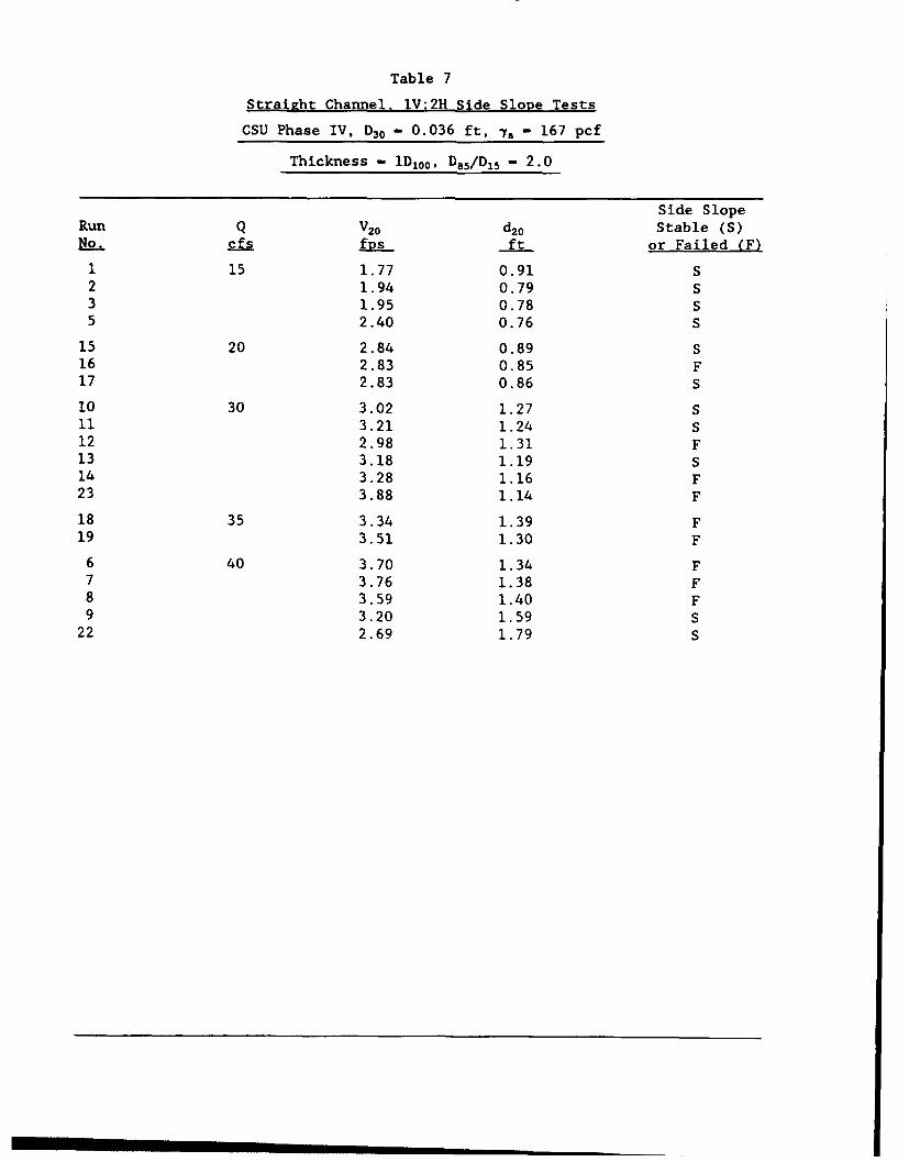
Table 7
Straight Channel, lV:2H Side Slope Tests
CSU Phase IV, D30 - 0.036 ft, -y - 167 pcf
Thickness - iD 100 , D8 5/D 15 - 2.0
Side SlopeRun Q V2 0 d 20 Stable (S)No. cfs fDS ft or Failed (F)
1 15 1.77 0.91 S2 1.94 0.79 S3 1.95 0.78 S5 2.40 0.76 S
15 20 2.84 0.89 S16 2.83 0.85 F17 2.83 0.86 S
10 30 3.02 1.27 S11 3.21 1.24 S12 2.98 1.31 F13 3.18 1.19 S14 3.28 1.16 F23 3.88 1.14 F
18 35 3.34 1.39 F19 3.51 1.30 F
6 40 3.70 1.34 F7 3.76 1.38 F8 3.59 1.40 F9 3.20 1.59 S
22 2.69 1.79 S
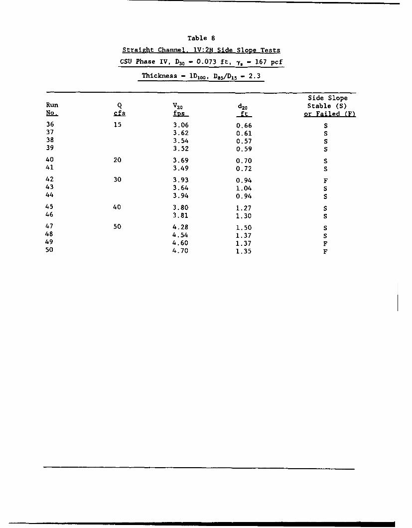
Table 8
Straight Channel, 1V;2H Side Slope Tests
CSU Phase IV, D30 - 0.073 ft, T. - 167 pcf
Thickness - 1D100 , D85/D15 - 2.3
Side SlopeRun Q V20 d2o Stable (S)No. cfs fps- ft or Failed (F)
36 15 3.06 0.66 S37 3.62 0.61 S38 3.54 0.57 S39 3.52 0.59 S
40 20 3.69 0.70 S41 3.49 0.72 S42 30 3.93 0.94 F43 3.64 1.04 S44 3.94 0.94 S45 40 3.80 1.27 S46 3.81 1.30 S47 50 4.28 1.50 S48 4.54 1.37 S49 4.60 1.37 F50 4.70 1.35 F
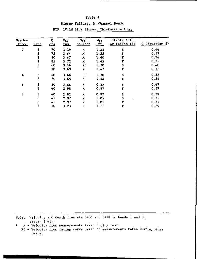
Table 9
RiDraR Failures in Channel Bends
RTF, lV:2H Side Slopes, Thickness - 1D100
Grada- Q V20 V20 d 2 o Stable (S)__on Bend cfs fDs Source* ft or Failed (F) C (Equation 8)
2 1 70 3.39 M 1.53 S 0.441 75 3.64 M 1.55 S 0.371 80 3.67 M 1.60 F 0.361 85 3.72 M 1.65 F 0.353 60 3.46 RC 1.30 S 0.403 70 3.69 M 1.43 F 0.35
4 3 60 3.46 RC 1.30 S 0.383 70 3.65 M 1.44 F 0.34
6 3 30 2.66 M 0.82 S 0.473 40 2.98 M 0.97 F 0.37
8 3 40 2.82 M 0.97 S 0.393 45 2.97 M 1.05 S 0.353 45 2.97 M 1.05 F 0.353 50 3.23 M 1.11 F 0.29
Note: Velocity and depth from sta 3+06 and 5+78 in bends 1 and 3,respectively.
* M - Velocity from measurements taken during test.
RC - Velocity from rating curve based on measurements taken during othertests.
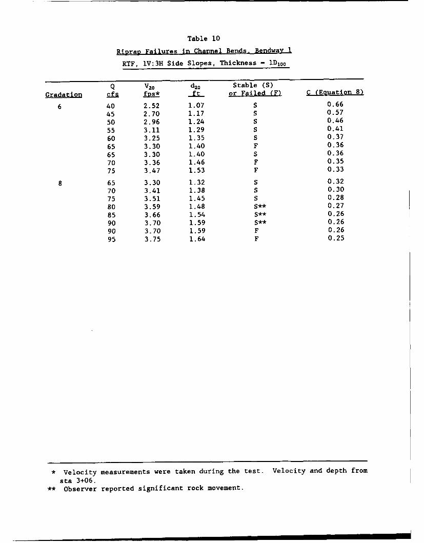
Table 10
Riprap Failures in Channel Bends. Bendway 1
RTF, lV:3H Side Slopes, Thickness - iDj0o
Q V20 d2o Stable (S)
Gradati cfs fDs* ft or Failed (F) C (Equation 8)
6 40 2.52 1.07 S 0.6645 2.70 1.17 S 0.5750 2.96 1.24 S 0.4655 3.11 1.29 S 0.4160 3.25 1.35 S 0.3765 3.30 1.40 F 0.3665 3.30 1.40 S 0.3670 3.36 1.46 F 0.3575 3.47 1.53 F 0.33
8 65 3.30 1.32 S 0.3270 3.41 1.38 S 0.3075 3.51 1.45 S 0.2880 3.59 1.48 S** 0.2785 3.66 1.54 S** 0.2690 3.70 1.59 S** 0.2690 3.70 1.59 F 0.2695 3.75 1.64 F 0.25
* Velocity measurements were taken during the test. Velocity and depth fromsta 3+06.
** Observer reported significant rock movement.
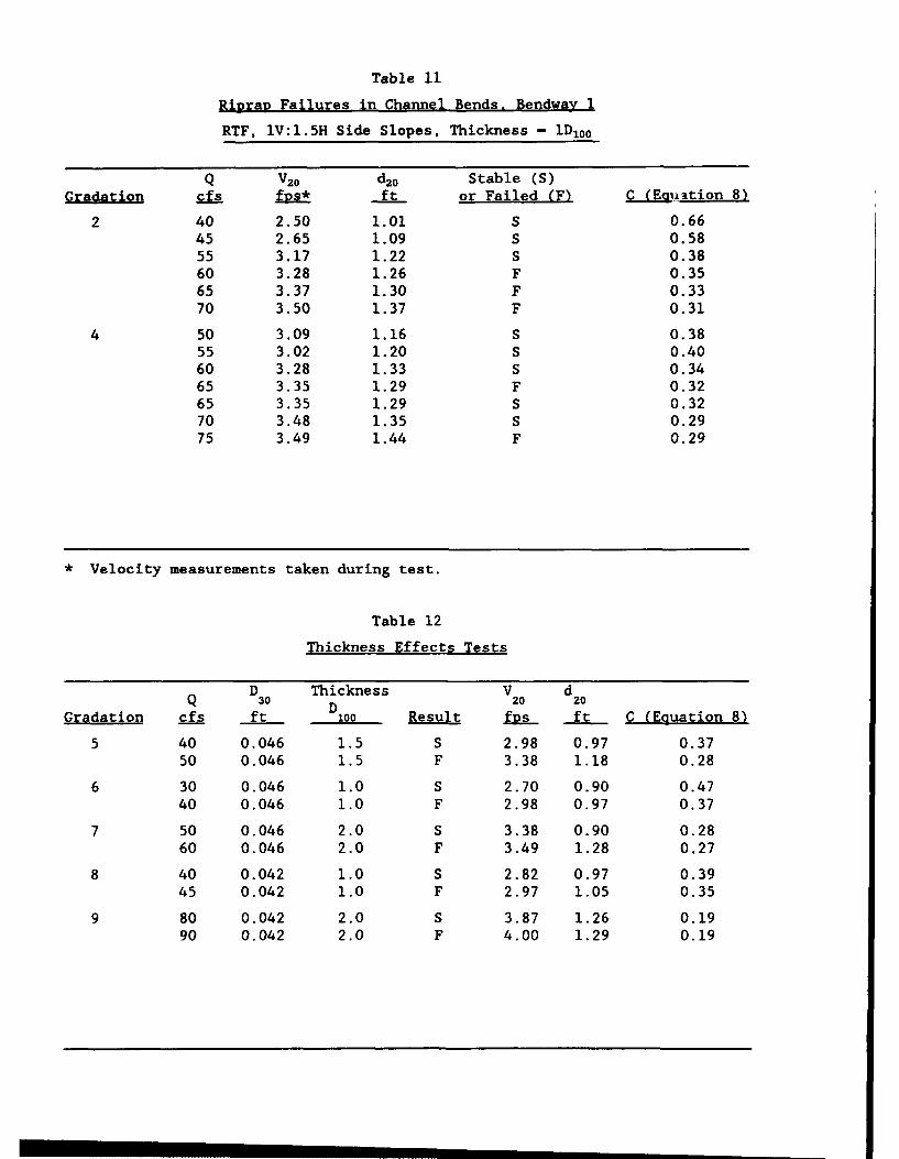
Table 11
Ri1praD Failures in Channel Bends. Bendwav 1
RTF, lV:I.5H Side Slopes, Thickness - 1D1oo
Q V20 d4o Stable (S)Gradatio cfs fRS* ft or Failed (F) "EUAation 8)
2 40 2.50 1.01 S 0.6645 2.65 1.09 S 0.5855 3.17 1.22 S 0.3860 3.28 1.26 F 0.3565 3.37 1.30 F 0.3370 3.50 1.37 F 0.31
4 50 3.09 1.16 S 0.3855 3.02 1.20 S 0.4060 3.28 1.33 S 0.3465 3.35 1.29 F 0.3265 3.35 1.29 S 0.3270 3.48 1.35 S 0.2975 3.49 1.44 F 0.29
* Velocity measurements taken during test.
Table 12
Thickness Effects Tests
D Thickness V dQ 30 D 2o 20
Gradation cfs ft 100 Result fDs ft C (Equation 8)
5 40 0.046 1.5 S 2.98 0.97 0.3750 0.046 1.5 F 3.38 1.18 0.28
6 30 0.046 1.0 S 2.70 0.90 0.4740 0.046 1.0 F 2.98 0.97 0.37
7 50 0.046 2.0 S 3.38 0.90 0.2860 0.046 2.0 F 3.49 1.28 0.27
8 40 0.042 1.0 S 2.82 0.97 0.3945 0.042 1.0 F 2.97 1.05 0.35
9 80 0.042 2.0 S 3.87 1.26 0.1990 0.042 2.0 F 4.00 1.29 0.19
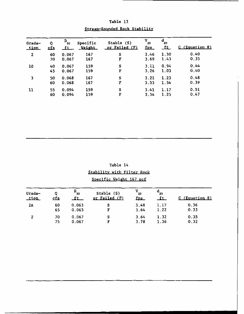
Table 13
Stream-Rounded Rock Stability
D V dGrada- Q 30 Specific Stable (S) 20 20
tion cfs ft Weight or Failed (F) fvs ft C (Equation 8)
2 60 0.067 167 S 3.46 1.30 0.4070 0.067 167 F 3.69 1.43 0.35
10 40 0.067 159 S 3.11 0.94 0.4445 0.067 159 F 3.26 1.03 0.40
3 50 0.068 167 S 3.21 1.23 0.4860 0.068 167 F 3.53 1.34 0.39
11 55 0.094 159 S 3.41 1.17 0.5160 0.094 159 F 3.54 1.25 0.47
Table 14
Stability with Filter Rock
Specific Weight 167 Dcf
D V dGrada- Q 30 Stable (S) 20 20
tion cfs ft or Failed (F) IRj. ft C (Equation 8)
2A 60 0.063 S 3.48 1.17 0.3665 0.063 F 3.64 1.22 0.33
2 70 0.067 S 3.64 1.32 0.3575 0.067 F 3.78 1.36 0.32
aL +___+
00%
cu'-4
I.-
Ld =
10 -C6
>~ C3
LL- -
< Lad
mLT 1
z
__ ____ _ __ _ o
w__ ~ N
LiJ
____ ___ N
___ ___Li
0L
CD \l CD CD C) CD D
LHgIJP\ kE[ ?3NIJ iN3383d
PLATE 2
I- CD )
z c
CLJ
Lii
C3 ____ - - C
tm - D
0 0 0 0 0 0 0 0 030 ~ U) L (
IHOIA Aa~3Nd 1N3~N
PLATi
z
C?
co
LAJ
cs)
,-.w
iHSI3JA A• B3NId iN3O•Jd
PLATE 4
II III Illl I I II ll •I CD
___ _ _ __ ____ _____ CD
- . 1 0
o3 <
w
_ _ -_ _ _ _ _ _ _ CS
CD C) 4=l CD C ) CD CD ) CD C
iHDI3/A Ail 63NIJ iNJ33d
PLATE5
0V
CD- _ _ _ _ -- -
C0- _ ciO
CL
CD
LI-
LiJ
06
iHDI3PM Ail 83NIJ IN3383d
PLATE 6
F
Im
_ _' _ _o%
a.d
CD
D xo
6 0
Li
0
0D CD Co CD CD I D C') CD CD-
iHEI)3M A 83NIJ iN3N3d
PLATE 7
1V,.1.5H
WHITE
2'
WHITE.,2'I
2'
PAJINTED SWE SLOPE CONFIuRmlON
PLATE 9
1.0
0.8
0.6 Je
K __
0.41-,4-- MAYNORD (1988)
CARTER, CARLS[]N, AND0.2 LANE (1953), ¢ = 40 DEG
--- -- ULRICH (1987)
0.0 1 _ _1.0 2.0 3.0 4.0
COT E)
K = SIDE SLOPE CORRECTION COEFFICIENT
, = ANGLE OF REPOSE
CORRECTION FOR SIDE SLOPE ANGLE
PLATE 10
1.0
0@• * STABLE
d 0.1d
D30
0 0 FAILED
0,01
0.01 1.0 10.0
Yw )0.5 V
VELOCITY AND DEPTH MEASURED 20%
UP SLOPE FROM TOE
THICKNESS 0D10 0
RI~RAP STABMMSTRAIGHT CHANNEL
lV12H SIDE SLOPE
PLATE 11
1.0
-PM=O.3 6[c( 7X-)0.5V]2.dl Lw rKgc4J
D30- 0.1
GRADATION STABLE FAILED2 A A
4 U C6 0 08 x X
0.010.1 1.0 10.0
Yw P.5 V
VELOCITY AND DEPTH MEASURED 20%
UP SLOPE FROM TOEWPRAP STABLTY
THICKNESS 1DI 00 CURVED CHANNEL
1V,2H SIDE SLOPE
PLATE 12
i.d 'Hid3C[0n C)) LOCC
CUj CUj CD C0C%I w
v-4 -J-J3
z oC3C 0 r,
C>,
GI-
a-)
________0 I
M' x
Lid
a-
CuMI-0w
C) >
Cý Cý Cý C
SJ'AiIOC-13A
PLATE 13
x0.9 -
0.3
/x04-
0.00.00 0.25 0.5 &.75 1.0 1.25 15
VYvyv
0 AVERAGE OF 21 VELOCITY PROFILES
FROM STRAIGHT FLUME, BOTTOM RIPRAP
d/Dg9 0 FROM 5 TO 13
AVERAGE d/D 90 = 8.3
-- BEST FIT LINE OF STRAIGHT FLUME DATADATA FROM RIPRAP TEST FACILITY, BENDWAY L
GRADATION 6, NORMAL TO SIDE SLOPE.
20% UP SLOPE FROM TOE
VEL-O~ffY PROFILEX 60 CFS STRAIGHT FLUME, BOTTOM RIPRAP0 65 CFS VERSUS CURVED CHANNEL, SIDE
SLOPE RIPRAP, STA 2+8L lV13H
PLATE 14
Lo,0.0
x 0
0.4
0.3- -
(L /X
u a 0 2 5 a m5 &7 5 1,0 1 .2 5 1,5 0
vy
v
0 AVERAGE OF 21 VELOCITY PROFILES
FROM STRAIGHT FLUME, BOTTOM RIPRAP
d/I•90 FROM 5 TO 13AVERAGE d/- 90 = 8.3
BEST FIT LINE OF STRAIGHT FLUME DATA
DATA FROM RIPRAP TEST FACILITY, BEND)WAY L,
GRAD)ATION 6, NORMAL TO SID•E SLOPE_,
20% UP SLOPE FROM TOE
VS-OCRY PROFLEX 60 CFS STRAIGHT FLUME, BOTTOM RIPRAP
0 65 CFS VERSUS CURVED CHANNEL, SIDE
SLUM PE RIPRAP, STA 3+06, lV13H
PLATE 15
AVERAGEI d/I9II8.
cu
C)r
C~z
CU OCJ
Liiz
al:C'U ZO L
1-4~ 0 C') F-
if < z I.
<~ ZD 0
'-4 0 Lf)0U) L 0
LPI~ ~ ~ I.-y Z C
W(r) Ifl zi ZH -'
cu H~ Lo L zif I[ I
in m
HD LCDu
PLATE 16
Li(L
0
L6~
0D
LI-
uw
LAJ
Lii
82+1 vjs z z 200 0
LL. u- .
PLATE 17
cu
Lii
LLI
- - - - oCV)
Lii_ _ ~ N
CD C C) ) CD C) C C) )LCOD %D Lf) v CV)Lc
.LH!)3A A 83NJ LN33N-
PLATE018
APPENDIX A: VELOCITIES
LIJ
Lin
I-I
hi> .>
L) z
> < --- ,
0% -4 ta-20: q. , Li.
cu~ d
LaCL ZR J
>00
So
"'-(in
so*** 0PL+EA
Ld
0~
C43
_~j L
> > w
- L. zq
(U)l ------dLI
CL. LIL> h. > C
U-m
(Uz
LL c
PLAT A2
ON + L4
La -L.() _j cd _O
0) Ll cl%
...JLaJ L Li
>it Li 1
Li>
Ix 0
NqOO(1I L) 0 L
0~ CDC,
LL. m
+ -4CD +)c1r) CV
Lai4
-4J
PLTEA
LLIa.
> -J'C]'4z
C3 -J U :
!9z , Ld~
0 100+ W U >- 1&JCV) > 0--
1-J
94(
LILM~000~~~I 0 L 9 0
0 0 Oem
0 o05
PLT 0A4
'4LAJC- JD
'4)
I-L
z )- Im
IJJ )-~ 0
!* 0
L) E3 Lj
La. 0-J
> , La
- .,Lid. 606 l to - IL
L)
PLAT 5
M
'p z
%LI >p I- m"
Lii> W
Q-.J -C3- ~
W4 w -0 0
Cu U,
Cu >
4.4
CD,
L6J
cli W)
000~~ 0000 ,0
CD -.?iv -t'
CV
PLATE A6
LA LO
La
*004 060000 0000 +LCl ---- i
wzz44 0
J~
Pt W
+0 IX .
0001 000 00 0
LAJLI
9L
ecuu0090 0000 see + C
~~cu
IPLAT A76
"LA
U'4 I Ua 10
C14
> _
M L)
r, -4 L-
0000 +-4 > -L
cu. (V) cu %inCuw
qic cu IXLACV (Y)V)
.4 -0*000 00000000 - t>
_j ~ -d LLL. C3 -
P. _'4 LLCL S
za > 4n
CC'S
PLAT W)
z0
44 1-
LIJ > x
ii>
II '-v- 44 I - - 0
d a. o.---- .A
cii(u2 wr0 CD CV __ -. '4
*eeN@0eOOOOO +CA
CD~~ ~ Idrtr ~
LL)
InU C?
Ccu
0 VA
PLATE A
LL.
CL cu
~v~OD('fly)D %Q (') (C) OD) (y Cj(_l . a. cu
I .4 m I I II I I I I I 1 illC
V 0% r- 0 W
AI A A A A A In PtR.
CY) ~ ~ ~ (V M' (') C') C' C)
ID C) I I I I I I I I 1 11 1
rtN N N- %Q 1r) D'W ri, %f
r- .CV) II I I I I I l i
CD. N N N V D In 04 C
W? ~CU a cli i vi I. ci ci II
LiJ
I-.
zODcu %00 %q cu %D Al L
0 C3) tiI m 6 III- cu a.
LL. CL La- LL. Z
z i & zza> t 0-
ul 11 R C lkqr CLIf)~~~~ZLJ %D% .C) tjcuW
LjCLhJW -C
L)> I.-
PLT 0 O
0- I
cu
v% m m m m wew CUin m I I I I I I I I I 1 1 Ir
Q% C* r-r- I" -Pt r: ' r-t 1" q W --! w111 % u in m 1 LUJ
9n e) lI I I I I I I I 1 1
wI in Pt I' I I I
CV, q 0 w r
N. W1 ) U I I I I I I I 1IIc
WCU i CC' CV) I V ) M' CM C')CU cu-
zIS - r- v r%~ IVC:?. v'C r C'n() C utW.CD M I I I I l 1 1 0--
I.. . 14La zz La'
Inc CD W Dqa. -J
CI %j I II I I Co -
z 14J z
O~Lai >: z-0I-I
IT~~~~1 Vc u 4L
> I- -.
PLATE All
La-
UJN r N r~ r.i n
ii I a Oi
%D( q OCIO 0p (p OR q q Nl CQ 0%('f
ýD ~ i cu m I I I I I I II I
e0U 0ý C W a? a? N %q n'
% ~ CV) I I I I I I I I 1 11
C?~ . *.ý0 C
(V U I I I I I I I I I O
Ix
La I I I I
(r. o, m' ca..q. La
CI I~l(
-~r LA-
LO OR (W) M ' Cl u CU.4 COD c U I I I I I 1 0 -J a
I. L aV La> a-
z UJ -
0ifl WI III ~Lj La
La> La
La U Ix
Li a
>Iz
PLATE A12
IA.m
cu
0%W N N N N0 % VW'c
in (%j t) I I I I I I I I I I 1 1 c
ui C s I I I I I I I I I lII I I
% O.C' cu I I I I I I II
Li. mII mo_
L.i
w n c (,0 m0 r, vy%
z
0MM N N. '.u %_ '
0 U I I I I 1 11 W- _I L. Z
zi wZ
Z D iM)V C') CUU-.. w
~~0CU II I lii()J >
> L3 -j
-j --
0 ~> > ILiiW <
ELu
x C' I z
PLATE A13
L&.u
n cu m I I I I I I I I I I1I I11C
W cu en I I I I I I I I I lII II
in ~ MMm m m m mr.
CD~w W')' CD) W' CD C) C') r, I CD)C'CU..
ID .nI I I I I I I I1 111
in(' w' m ' m ') C') m' mm_;'
L&~
IxI
z
C')C) OD ) C') co~J U
m M-~ Mc
on La ''.0 . . . r-.'. C =
L~.
W O ) C ') C e uc. .( P V ?; i I I I II w >Z -J
z w >
>~ >
< zCL
PLATE Al14
W%0 0% 0 % %~~ C') C') ') C' c'i C')D
It) 0% 0 % N t %C?
%D c II I I I I I I 1 1
- C) 0% 0 0 N 0 OM 0
Q')C') C') C') C') a*, a%~
r-. C') U. I I I 1 I1 ODIc
LA.JCix
0 NN'(' N ' %Q O -nL
N (V' L&J II I 11I.-x
zV) CUe CD O %D CU a') LIJ
LL. 0_ LI- a U-
CDC)z Ij -
CD~ UC WCUU.1. -
z LLI Z
LLJI
L.J >Z I Lai
LJ )
L) ' 0:
z Z
PLATE A15
I.-Z
C)
-6 %Q mm m m v v m% m m mCN
In m II I I I I I I I I I I
I 4 () I I II I I I I I 1 11
0 q q q q -!q C' C' ý II q
() U I I I I I I I II !.
M ND CDU- n 00
LLJ I iI
LaJ
CD tvN U)i
La.Li z
t OC' NI I d- I II
w _j
CUO% Uin ~ '~C" CUC
Z _j LJ 1
1LLJ uzw~3 <ED~I.
' 'i CL DxI >~ I
PLATE A1
IL,LJ~
FC)
cD CD V) Cc cu*c~0 W~
uigcu~' It 1 I I1 1
44 4 4 4 r ) m ('cu cu-
%o w4 IV I I 1 1
CU CUCU O0% Nv D CV)
ri~C L)IlI I I I I lI i 1-1C
ini
r% 04 Cv L& I i I I I Ii1i1IIx
LI-
0 LV) 66 CI ill CU u.
L- jL A J
LiJ
OC6 'U~ I I I ItO I.-4
z Liz
LLJi
Li w > Li
u i LLi4jCii <
z uz
PLATE A17
CL 0
LLI
Un ol vi I I I I I I I I I LOi
in c? C? C? q ' %') TC.
If t)CUCV) I II I I I I I I I II
%a cu CV) I I I I I I I I I I I
%D .4 CV I I I I I I 1 11
OD CD m W-.1 C').
r-C' m ) u I I I I I I 1IIIC4c
it
CU ~ C' CU ' OD ) %D O LA
r- ) - W I' L I I I I I I
LiJ
z0%- CD)' v' tv) CD )C(J. w~
-La
Li Z
CD CU I I I I I I-
z Li z
ci Z -J -J
4> L
LA..
Li>
=I C' ?
PLATE A18
CL.U
Cf cum c_
V) -! 0-4 4466 L
if) r , mi I I I I I I lii
WNe N WýC MCwn~ ri ~ ~ (~()Y
N n m~ N~ m U N N 0 N C
N ; CV) I I I I I I I I I I ii
CU CU r- n N %3 0.
mI p Ix I I I
.4CV Liii I I i 1 II
LaJ
SCU. c OD N VA %D % La
co ~CV Ia I I I I I I I M
L6W z.zz
Lr CCD CD m N N La.-
z LJ. ZLa Z
Z LLJ
M -C-
U. L..
LiaLO > > L
a. <Li'i L;
cu
CYCD
oCU 111
q 7 iU iqlS0cm ~ I I I I
W
L)&
V?%D W4 " L q j
z0 LLI
co -
Lý zz LI -C
CU C f ?C ýNCu% e -j 0.
NJ (.1 oJ~
WI z
W - -
LO I I I I I I I I I I I IZ L AJ> >
U> 0 LIJ
u I L
%N CDC ?C !m
PLATE A2
a,
U- CD
trC' C' C (
t n I I 44I
C.)3
%D- .4 r'-C').1 1
00
z
40
(UD q cu c LA.. i LAIr-- c;IIII 1 LA. z
Li z
CL
I D I.- LJ.z Lai z
LLaJUL >-J LAii
1=~ Lh.LaJU u
C3 )Im ck: mL
z
PLT > 2
cu
'U ~ (U0
'5OD&A-~
-
Li c
L61 z;V
'OoC c I I I III I I-1
PCeu Ic cu zu c u O
La 0%0V) 0 U CD0
t-t W4 ojo%d c;ca > I I I I I t4
z 14
0-
Lr)'T u -i i 'i 0~. :0II CD L-
PLAT A22
w ru
I-y
La n
~V
Vr Ul V l CUOWV
1 CU m'' M' m' CV) mC (w) fl)( CU -
M A e'C) CV ) m M ) CV) CV) m c~u %
0 0 D Q tQ"
OD W' C') LA M LMaUz
Laiu
-4C- - qo
RCU Ii 10
/, C z LIJ
D cucu . LJ ai >ORi V! D
00
l >j L.LL a
> LaL)~
iZ La
i C') Dt
x > z
PLATE A23
w
0 0W
%q %q Zil q-
r-~ ~ ~ I7ý tý v
D m I I I I I I I I II cu
r--. N %D LO vo
m II I I I I 1 1 1 1
6 mi ci cc~u~o/N W O C 4 C'C) C' '
LhJ
z
Z CL -
cu( cuc vu cu L61 CL
rOCD u I I Ji iIIz L61 z
'cIf Z W -J
In to
CD M < F-I 4
C')wI CL
PLATE A24.
0
.~.%O
lz 0
a! e0 C ,C n'
V: M m m CV) Cl) (~I
V) .-4 CV) k II I i i
Qý CR CR C CR Q r,ý N2Lp m Cl) cn C" m M N C
eni
N .cn I I I I 1 1 I LIIiz L 2
LO~ I- e% vi > I I I
mn LA-J CLL
c~~u ILi z
z
e LJ Z
LL >> -*
Cý CU Z Li
LnI In Co -!?
Co CD7! 7= Z _
PLAT A25
03cu
al 0
ODW w w 0 P 0% 0% uc'ir e'i 6 ' ci pi 6 C'MI I I I I I I II I
M'' M c') C') cv) C'W (V) C')McU CU.
OS CU as M% 0% r- W
F, i H 6 H 6 6 M i W W
W) in i esvi0
LOYC' w C'7 C) CU~ 40D li
LdLii
0) C0% r~ 'C C\CDC %000(f
r-ou PI Hi ri (i - CDC
r-o6ni L61 L-Li
uI.
CuCD
> wi
M Z-
PLATE A26
Euit, .- C')i I i i
ll IT IT C1 aqIT a ,
Cun t f CY) Cl) ClU cu....-%0.cu i i .
LO _
(V' c')c Cu W CU( .- ii
%D u I I I I Ii I f %
mr-c ri :. Wwcu
ix LD
1)r N I- cU cj jcu.-0 cu a.6
LL)
LO.- ONil L6
z L i-4
z~ Li
Z uj LaZi LJL~ >> 3 AU-4L
4jLo .
C'3 < r 1
0- C
PLATE A27
wc
UJ
Lr? r% r?
CU % CV) M ()CU CU C0
cr cic m mu CF) .cuII rcI I I
cv) cu
D cu I I I III I -w
P- 0- <I- cia o ld ;
2 U
0i z
Lj CL 0
_j U-
LJ P.- u
M <Z YM j C
PLT L6A28j
Cu
F"
C)
In06 W
in q ( C ' C C') q C ? q C')') q wL
V) Lq () W Cl) CV) CV) CV) CV)cuUn .4CV) I It I I I I I
Go)' C? C'i cl ) C') CU C U ýcc '
n ; w) I I I I I I I I IC
0 CD0 ) ý (ý r, Y c TI
v V? m m CV) CV) m' c~cu cu IM%D .CV) ~ I I I I CV)
L) (D)C) - ' .LAY, - M CV
%ocu vi mI I I I III 1-
z
In C) (2 ILL! w cr cr) C) 0 r-.(
M- Ci V5JU.~L&
LI-
z Lii <
W ZW3
Li
-a ~> C3u
w ~I-Ljo u
xLJO
C3 < ' .
PLATJ2
%6Lh.n
CLa
%0 CD) C ")C)C)U. m
Ln Luinc V Iw IV V m W)tiNiv
u 0 % 0% in o IV I co
c' . IICL. m- m' m I vI w cu Iu I I i
'F4
44 m "' > ~ I'*ICICI I
Lia
CL
U')C D %j cCU I.CD LAJ ZL 0zI (a ý
1--
0 Laq0 ID ZOI 4
1* CD 7-> 0 LaW
4 Li.
LA.4 - -
01
PLATE A30
Wqw
V) 0 v~ CV P c c.41 C41
v w
Oclu II I
CU w
aL
coc cu cuco'
a W. 0r 14 c ; IC U-a aw
~uLiJ _
CD r) c .;64wZ _ LJ~C; Z 'i >
> ip
In, w
PLAT <3
I cwaL:
qfqw w qr IV crwoW
*11 1
wq m CV) cu ~ w oI90 mq q q ~ C(
II I I I I OD
I- ~ ~ 'i' ts IWc~ ') (~ 'CU U Lii
iý z(Li
0%0Y i in mi cZ
z z
Li Liv C -
Z _j L> J Liici .4 1 Z w >
~0 Li.
PLATE A32
It (I~ cy eQ V7 cr-~U
Lo M II I I I I I lII II
%DW ? ~ 7 ' %
%Dc C-i C') H' H m C')
rd-;' in a) I I l
Lii
at w ~ c') cy) CD Lo i0' -RI ie 660 u-
N ci cu w I I I I 1 11
LiJ
m' 0% 1 0ýQ , QM, / WN .7 C CU ~CU j C4-
CD i Wl Ia I I I I- I -jLA. CL Lt
00 o CU I I I If CL -0 <
z Li
L' >:
U 0- _
Li
LiLA.J Lii
.- , c/
I 'i LL
x< >
PLATE A33
1)I I I I I I I I I l
r% D qUv, n Ln Uý v,? cq C4~N ! m twi 6' H' m' m~ m ' m C Li
gOo*C')Cm m' M' ' Cl) c)u CUo
II
M ~ U
L - cu c-W. C,
jCr
Li -
OD % oJ a. 1
L~i zm z L,; <
%D W LO- -T-. OD-CNa.
Uw
LA i
z l uxi 0 <i
0 <'
L~cu
NN4 CYC 0 N' w' 0Y v' (1 (7) CUU...
mD..C' ~ II I I I1 c
N 4 i I I I I I I I1
LAJ
CI c'5c C') 0' -j()C
L3 Li
j a- / <
_/ ww >I
uu =1 /W
Lii
LALi
xi >
PLATE A35
LII .4r I I I l i
InI
y IM(4~ ri 6 6' m' r6 cuu
r l al r ID I z C "
r- C~ u I I I I I I I
Li
1r)~ CD ~ C' 1r) IXU
-o cu LAQ I I I I IM 1I.-.
z L;
-/i
6..
Lla U
u W
LALi
i C:' <-
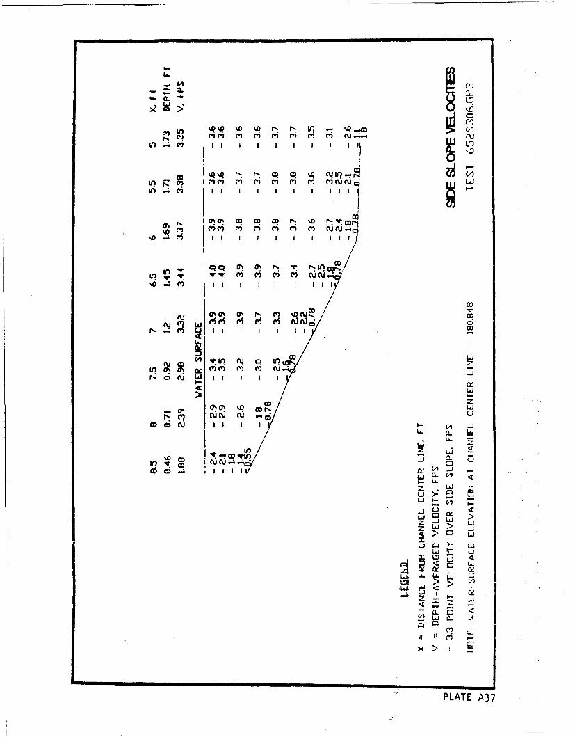
Py) cu-4_c
ol~ Ul
cu (I w m m mNW
It
IflO (D ')' C'q o' (U -
N ot;ID I I I I I4 Of
z
L- a. -J
Li Li
z S-co~~~ I!C 1
U <
PLT A37
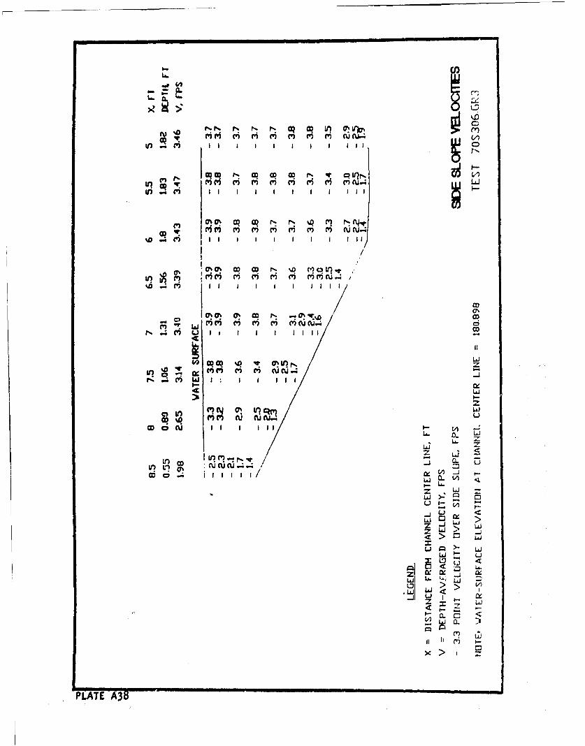
LA.i
10$0 O CO I' %D I I II
C'5CAi cu,- C3 ' ' ') C) CC~
%D. C)~U I I 1 111
LAJ
N W
I--LI-
(D CU III I I I~C) -
ILA. CL Li
LiLr) ý p qwz *j 4I (%i C%
I II I
0 >J
CL (
z Li L
U-)
7- C) i >v
:1>
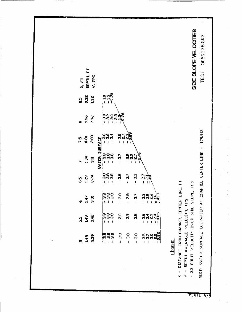
'In
iiii
rou 01111
CD CN CUN
W~~~% ~c IV'~ cu r- c'c -VLo i6 ' i icu
zCID CD CD N Li
m Li~
Li~
J C D CD CD ) OD ') C V7 C) Q .4 L
z Li
Li)- >ý20%CU . jUTIMM m In MOWNC' C') C' 5ciXj
u7.C' Mi I z1 1 III~
uL J LiJCD 0% x Lo
rC))' V') C3 C'V4 I I if 0 w q
.i ~Li L i
S a. .
w .
pi cv
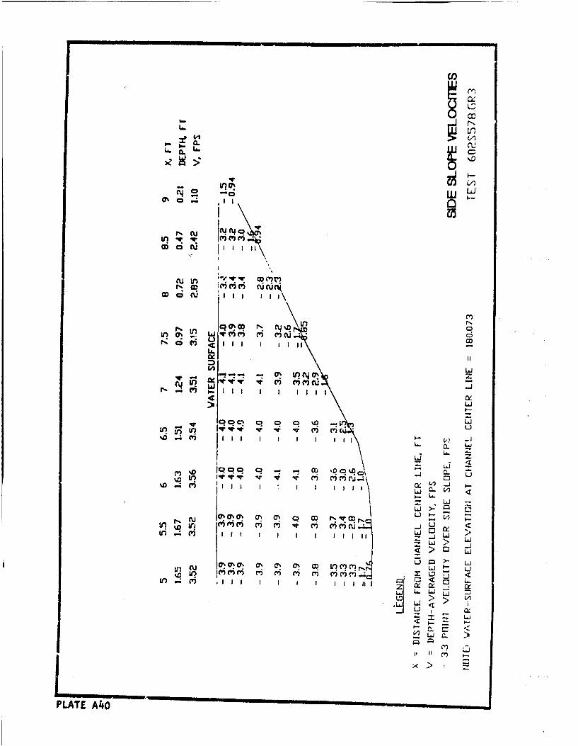
~~Lb
6. 0.
C2 u
06 ci w
I D im i 6 u U
u co 'C'C
cx
v 17! z
- L j
%D -1
)= Lt. -zi- Li
it I-~Li >:uLi Li
CU ~ )'C)L
Lf.q ' 1 1 1 1 1 11 11 _ A
'i > L
"=u LA
cr%~ ~ ~ ~ II a.) 0 7 .- m ,L
PLAT CUMO t
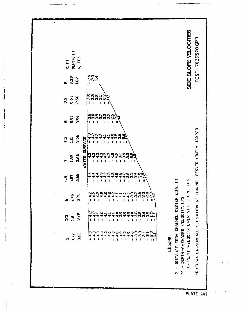
CL --
ff) 0 Cu III
OD a M' 1 1 1 1 1 1 1 II
m) m w ?e ycyr-V )q
Li11/) zqC W'
L! r* LA- CL LACD
. . .j
'i -i4- ;- e UAýco r't w
:z W -j
Nii C3 <
PLAT > n
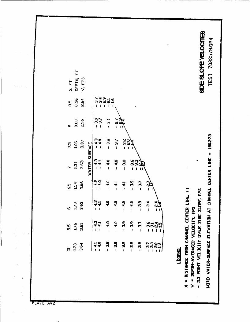
W6Lr)
CLA LL.
co 6 O
cYC ei C
u,~.ov cu, C.n I I I I-
IsU.
i 4 m I I I I I tIll II
x> I-
PLAIL Az
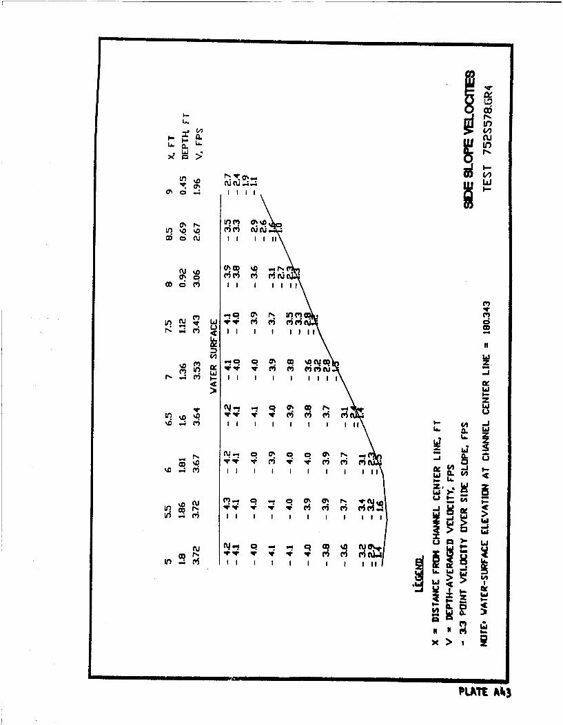
I-6LA.
.00
~0cu IIu liii
CU~f
M ,I I I li
C') L5
IdlJz
- CU~ 000 N% -
11 W IL W I I I'I.. L
ui 4 m I I I I I I I I I I I
x>t
PLA~t A43
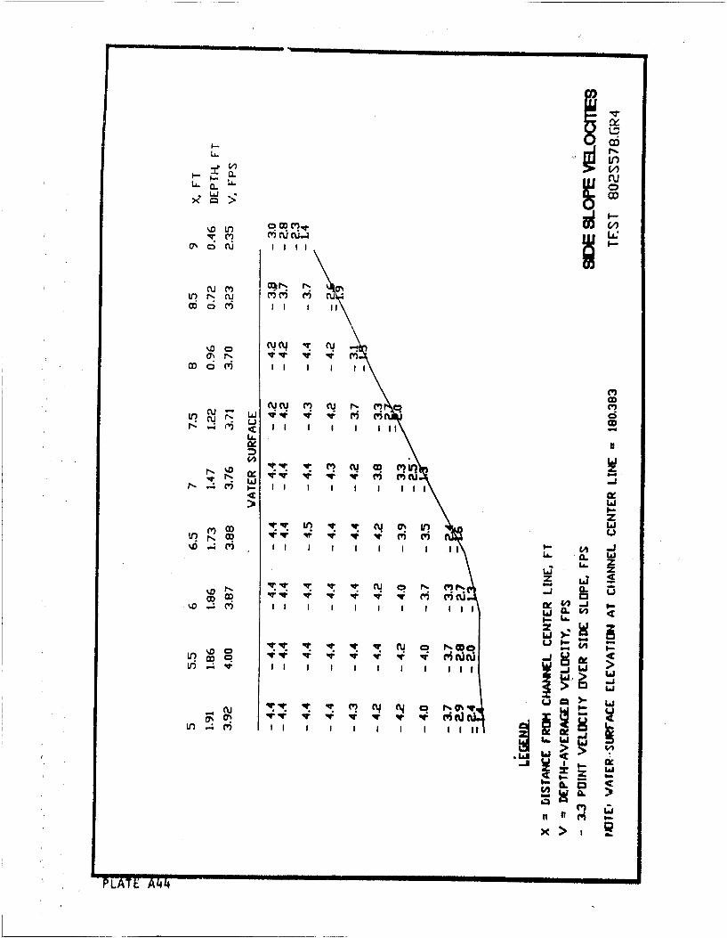
LL~>. UNLe)
CL cu
M i I t i I L
Vq r*. N CV) CVU acoI I I I I I I I '
CU CU C) (%j f. (w) r
N Ix I
> W
V?4
rnný eCL> LJ
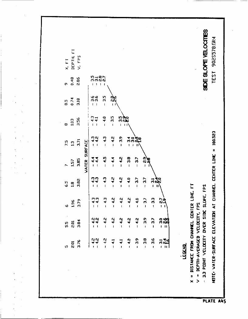
1..6
LA. W)0
M ~ ~ DL %D V O '
M" C" cuQ ~U
En - ~ W) M-m
c6 6I (v I I
M C'%'M CU s4'N ~ r 0 CDLuLr Cq* Li 4: M M " (6 CD ~ 4
It I I I II aV? OD 'X C
IJCb ~ ' .4 Iv I I I I I IIiI
or-r N -. U "C "C
In~ ' Ii I LjILI
wUu 0 V )N cy cq y cy cu (, N
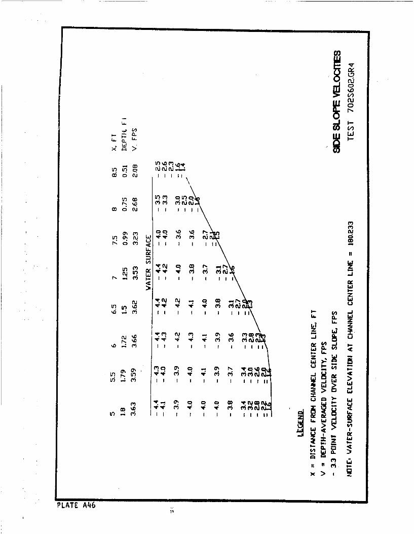
U~to WUCUL?
. L
C6 0i, N
co I I I II
r ) I I I I I I I i i~C', -
0w jr w qe Me 'W ('(u 6
Li.
ii -I i l u1 1 i
iii .4 i I I Id 1111
PLATE LA.
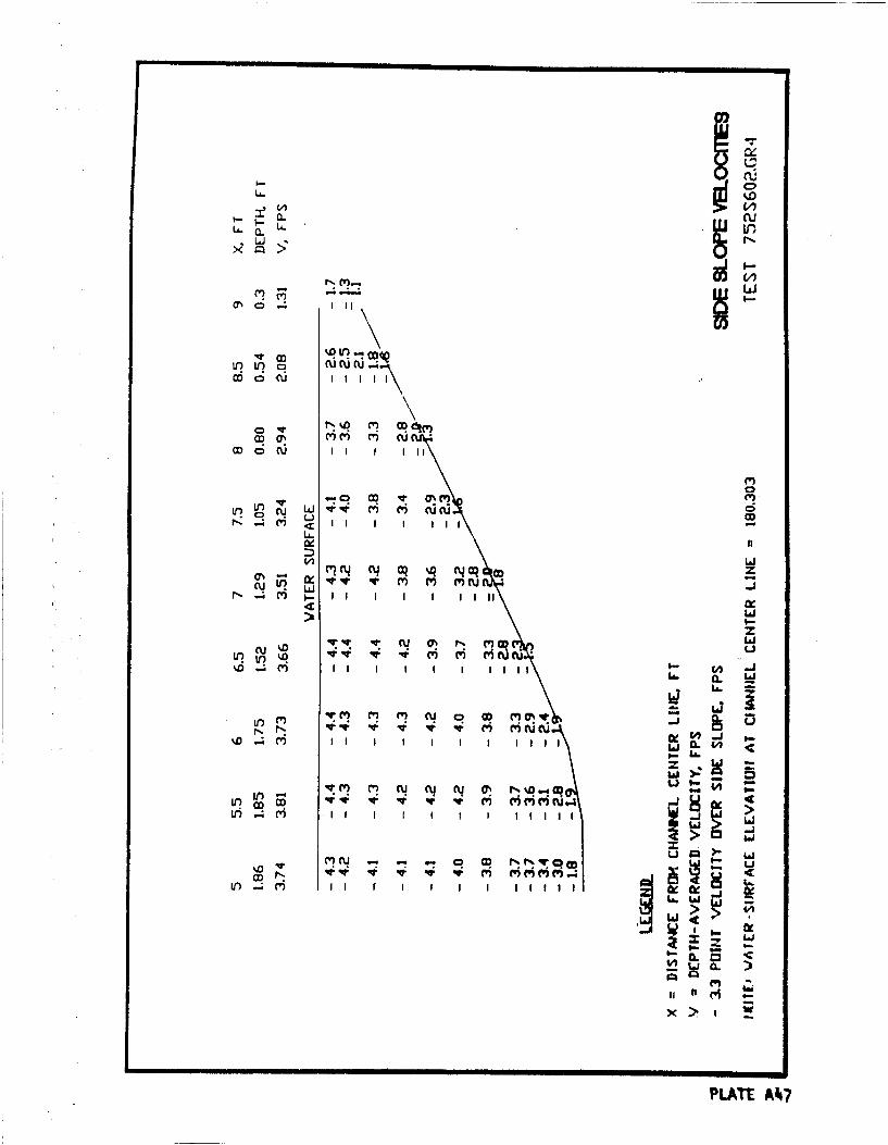
Inu
10 tn N% cuC6 Q 6vc C' C
m CD W n' j l(
('2 Ln C J V*I l 6 CJcCDuLA.
N Q%Q N Cq CD
(vi Cu cj~ ~
%D. a.
%D -i I I I I I I I I I I L1jO& IL W
@i I M r11i
II) I I I f I I I I I I j
0 ).M~I CU f' r V M
PLAT A4c
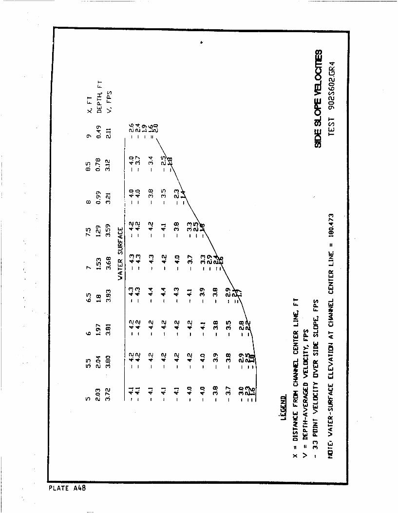
CIO)LAJi
ON %DI\
WODCU C) v I II
Lncu ri H .
ODi ~~ Li
L)i
CID m NN IV % z
LIJ
L6I
La.
NO W - JJ iII VI I I I I I Q IL~ W C
II~~. I I I I I
LaI
ON N a! a! N rq a,~
Cý Li
m~ c
V)~~~~ cu I l
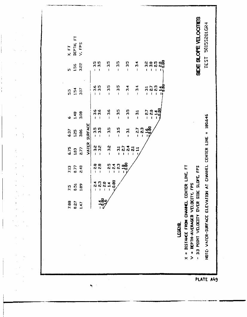
CDLA.
U. CL I(U) If fl Ilý
u CU iLc IQ Ir V) v uoLIc Lj
D'o .in l v) trLO ~ r'i Iw C') m c'6
%D 4 I I I I l i
u0< W)c in I) C') m' '
(u cu-
(V? ) cu L.N c
IiI I I
LNO N'~ LU-MI f Q .4
Pý r% -
/U
Cý L"
LI i ,
PLAT Al4u
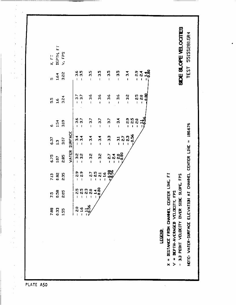
I- cuIn,
La.J
r-r- LO in '.o in 'r -m' (w c M t5 r s c' c i ru -;
Ln .4 Cy) I I I I I
m'C' (Y) CV) e') C') cu cu u%D I I I I I -
wiu ?
N ~~~ V: ' r%' 1 '
cu~J~ eq rq N'Ec -JC')i m c C') CU C R o
>11 Io < III L
-ý ou~ C'WU I~ Li L6
0o tj 0. tnM. CtlC Ju(u 2 rj cIiC)w C
N C'J I I I I_
Lo _j C 4
> 4n
x >
PLATE A50
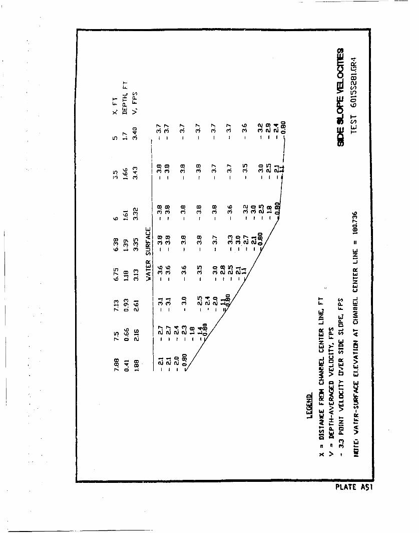
LL.
a.
0l N-ý r-l f U 0) VOD-L
N CY Ycr CV) M (1r m' CV ) fl
0 0 pU (0 D 0D 0 N- P O L
iim I - H l -i 6
cu ~ % qn CR q %P CY I
.D (w) CY) M' m' m (Y (W)m cu-4
Lli
OD~~~~~. 0.. LO C O LC c - M01
OD~I4. (6 6c u.4£
ii
PLATE.
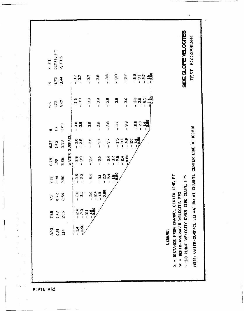
nICD
LOi
w %5
N NV('
M C CO c w' %D) C' C.-0 Lo
II m I I ~
%Di CV NID ~ t 0
u CO ('D CDU( rJLrNW W ejLi
4 - c'i :3 1 f I ti l
LOC' CU) ('7(d(0:
Ncu c
Wa.'W
0O %0 M 1) (1
wn IV: -CU ~ I~ %I!
r(' t-e
PL6T 7A52
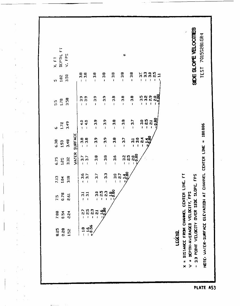
Lr)
LA. 00LLi
cua -ý C Q O o c o c ,c )i
C') CQ V? 04 0ý qM 00 mi ii, m V V) c-C) u
Uý Ln
DI I ý ý I Q q I -I o
C, -D
-- 4 ~:4-J CD
NOW II I lil
N*If~ ~CDu l~fJ
NC COOD 0 1% 4
kI M
m 4-J
coc Im
(D~~~PLT IIA53ucu A 6
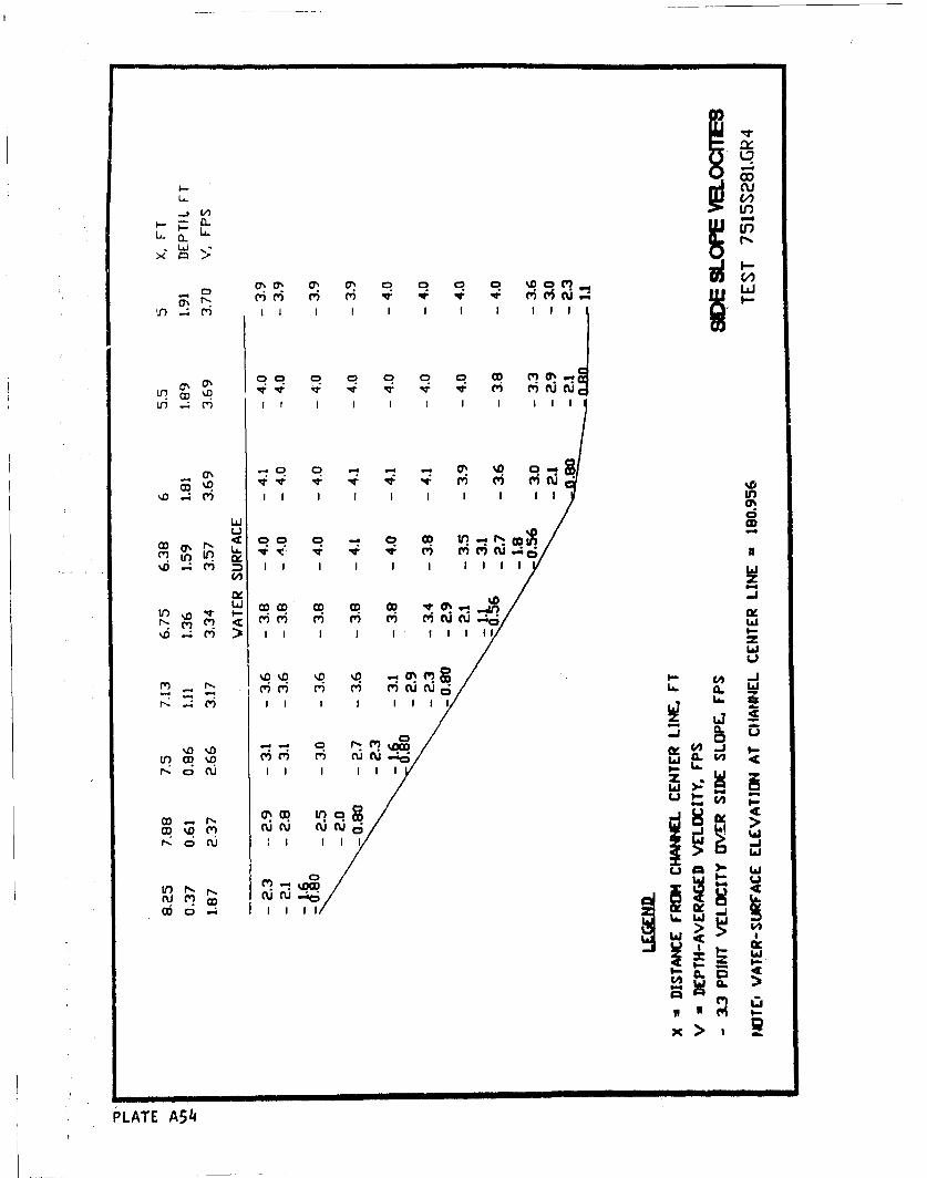
U-o
u cu
CL -
(Y)I i I I I I I I I I L
Ln0 0 m 0 0U 0u c
Li C
(n ... LA / c* 4 il m m ,u , , , ;
-. D
I.•. r..i m m H,>Q ;
tr O ,, IIQI I 1
CD> ,
In N
coo a;
Il l I I III I II I II I II I I IIII I I I
x A>
PLATE Y A54 hu1
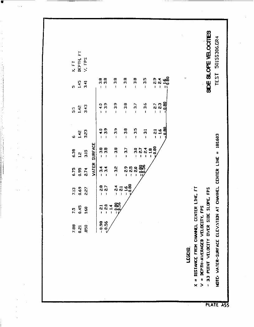
'6LULO
In . c') I I I I I I I lIli
r~~~~ ItmmmmI uc
'LO .4 m I I I I I I II I
w <
Ln in -u0L
ID C d > I I I I ! l1 lt
rd 1C cu C') CU UCUW%D OC I I I I 1It1La11
z Li
LL60A >
C'o0 %D ucue CDca% tr I_.
t'CR (,q >I i
4.. Ii3
U, 0 L,6~~00 0 ~ 7 (z
t~llat
CL00
it)
>
PLTEJ
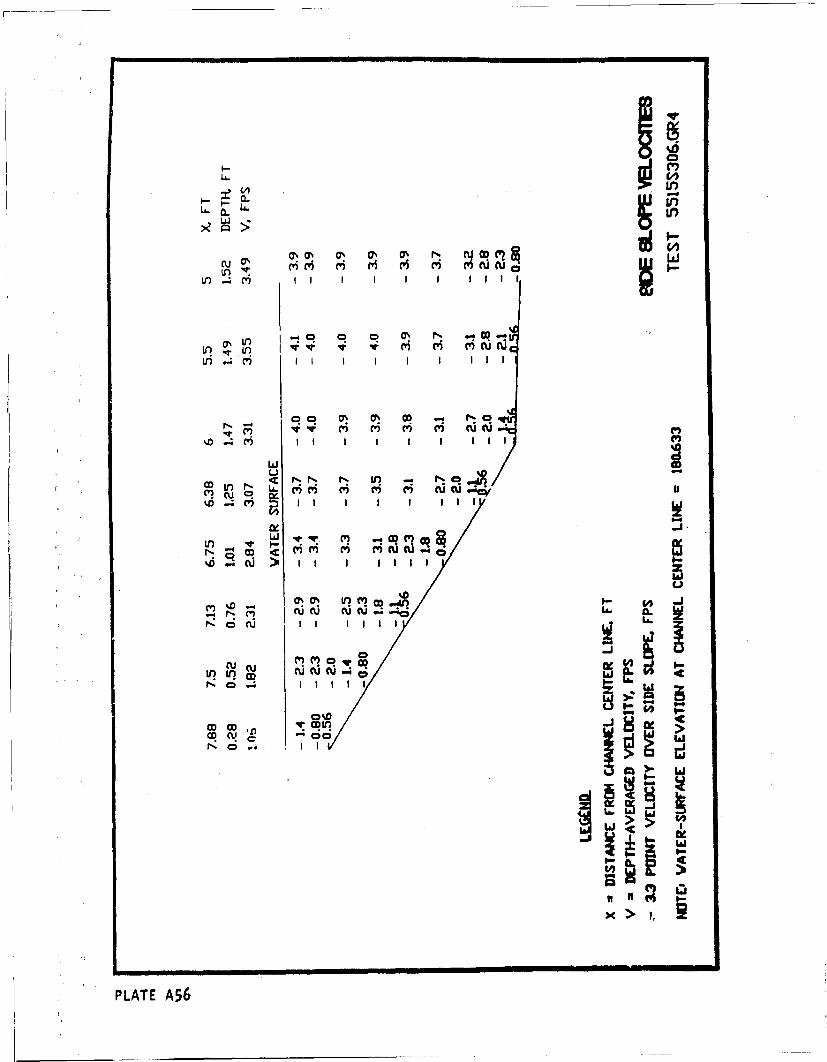
U- .m
~0
tn m- a
U') N
qr IV M# (Y V)m uC
If) I ~LL. Cu Cu
r! 0u (z I i IPLATE A5
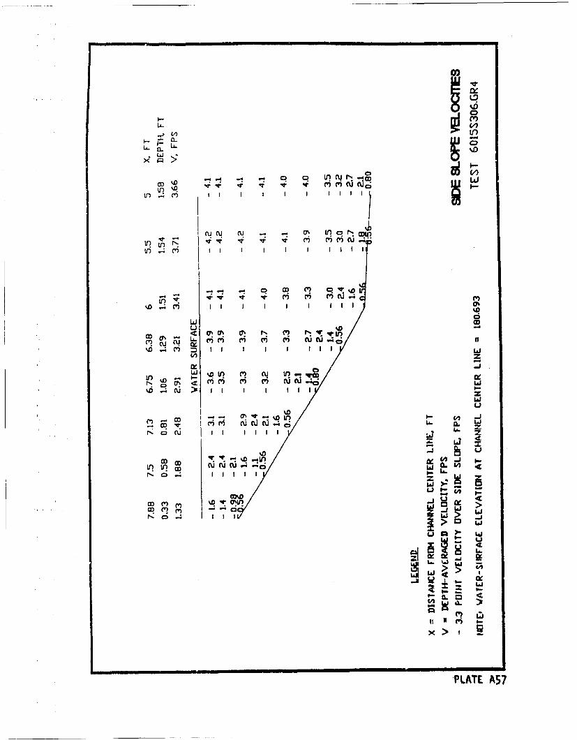
CV) CV)C)M Ju
LiJ ODu0< 0%Or N CV) r- qrj
6 .I c- I LaiI b
0.
()C') M N N NN c-ý > I I I I I I I
LI
I-- -40 I -1
Ino in ill DL.
Co M 0 I
>IR W
&" 1.
X>>
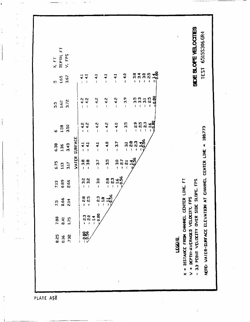
Ls.
-.D v V V5 ri cuI~
cucu c f lJ (U Ml 0' ,C
V? ID r' Cr c r i cu*Lo ; vi I 1
V)' CU CUj 0, U (Iu'
II .4 (y)I I I I-as
wL Ou
<' C') ('?EUO
RoCq V I D i
as %D-DV)-
r%0n CD;1 CVyC
uau
w >l
PLAT cu58LA
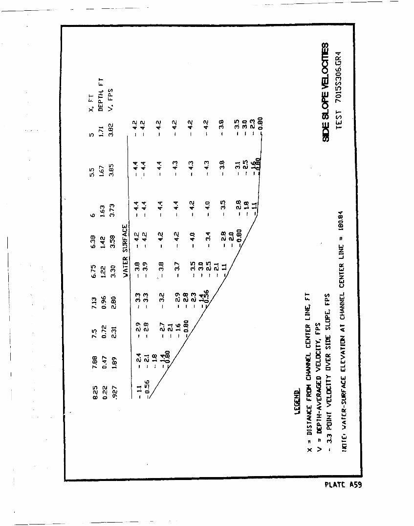
U.Cij CD~
Ii CU N U CD I? qIIIODL
V)~n -4CY
r, In I I I I
p %Dr q
%D .- C m~ I I I DII9
('(M ft D cC4c 0 C'r C ') JU.- . C
%D m Wý I I I I I9 I I1 II91
009
'D .4cn I I I I1 1 a
z
%D -J
Li S
CUj9 w w
r UI I I I I IL
>0in cu!II ?RPii A59c
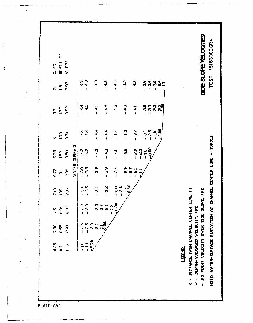
U k6
0.U U ! - )qI
LJ
CYC) m ' C'V" ) N CO qrU..v
tL.4e M I I II II
ViC' 0C')v CV) (U U. L&.
V: V: (I I C? CD
< UyN MUC(VI~r'0ocu J I 1111 ?0
IxI
in~~~~C U- L s S01'a c)
PLAT NA6LOv0QV
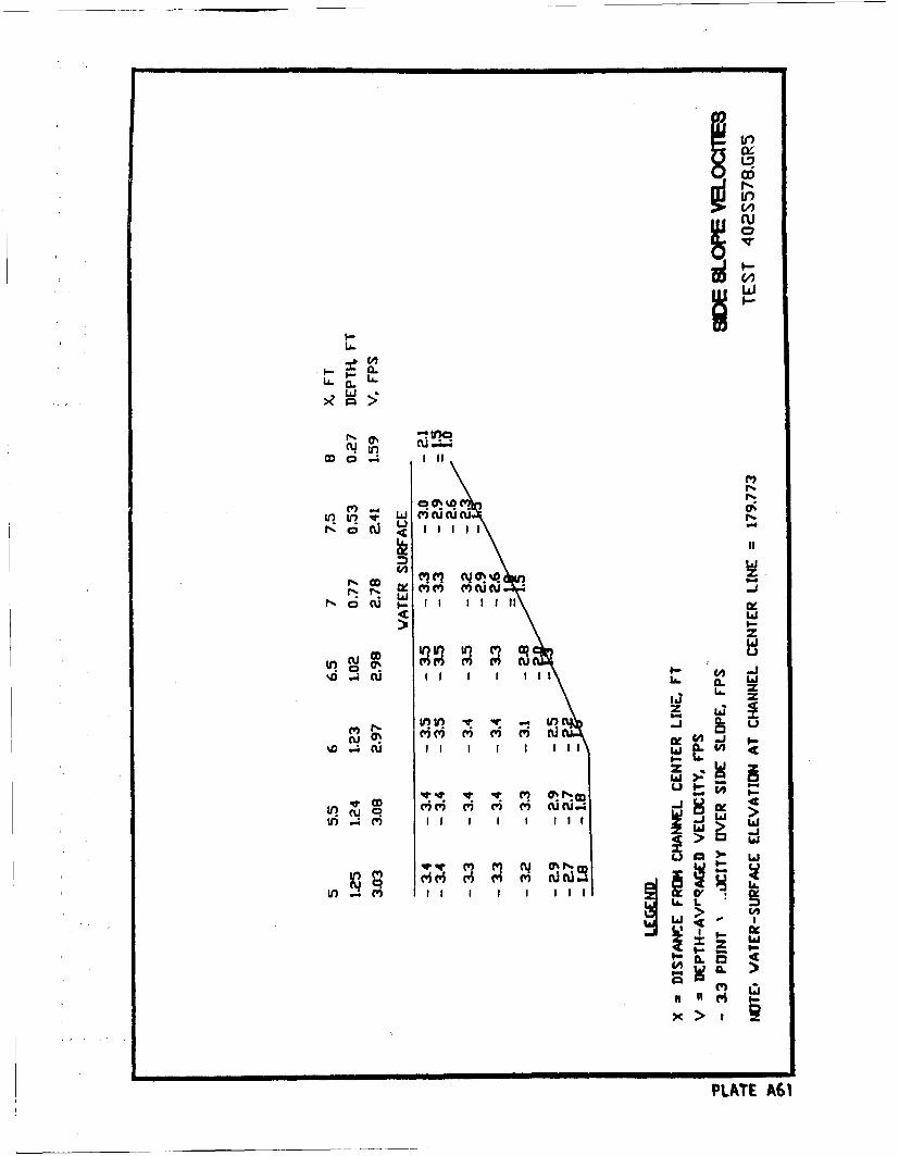
Li.i
ILI
in cu
M 4 0%) I-
Wz
I-I--
%DII I I I II L16 CL 'L
LA. m
-J i .
I >
PLTw~
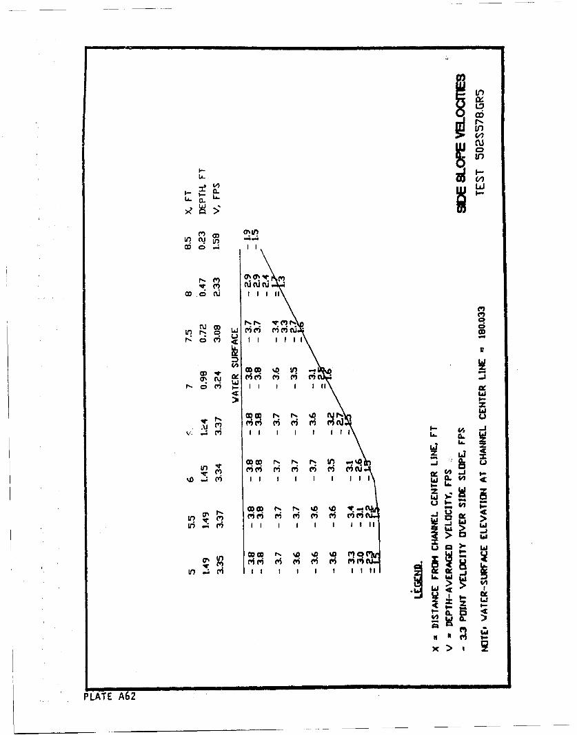
IIx
C6,
C,)r-r% ~,)IL%
LA-jci'i rici~a.c
No. ' a.lii
in,
CD . 1U a~'i 'c~-
Nor Mol M I I 1
CDN V
CD at%4l '~ -'
I I I I I 2 1
r I I!'II' IIcnn
i!iE e?
PLATE m6
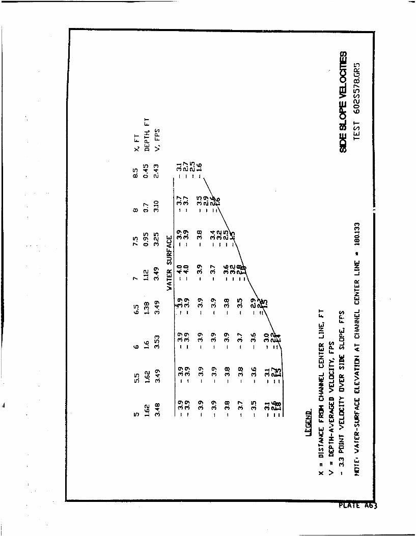
iiin
I- I
N CD)
UC 0
aoC) 411 I ii
m -J
Lii
tfl~~~v% C" " , C) oII I I I I . ~ w
w >:
CC' C7% mm " ON O CD ) 0 "I
L 4 m I I I I I I I I II w
CU W
I) m I I I I I I I 1III
w lb
x >
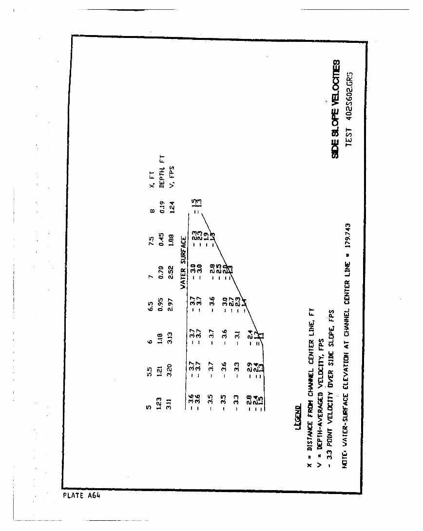
0_0
IL
Ln CDLa .
L6J
Ix
I=V r~i i cu
CL
ce -J-~ II ii
zz
ri i ri~ ti Ix
IL
win - C L?
.Jw .~a (Yew ceII I I IW
W L.L'
~ i-4'1
PLATE A614
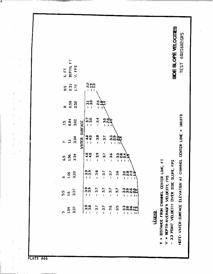
LL.
Lor u (Ic .-
co w cu, c' 'cV) L ) c
N..~~C .q C' 'SCn
co0 N ~L%Di
C? c 6 6' ri' c'S m' M.cu- mi0! .. ,
vi >a
v) I I I ,cI
C6 C
PLATE A66
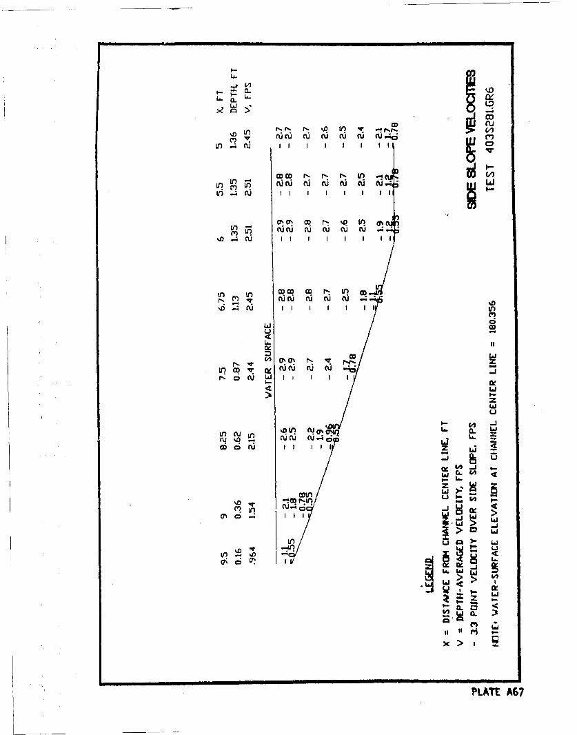
LA.i
LA CLJ( CU CU.U
C5,
CDJ cu
V) .4 I I I I I I I 10
10IOD0 - N L !(
%D _;cu I I I I I
LA..
co La
r,(,
Lol % a)- ucu c uo
j
x>II
PLu G
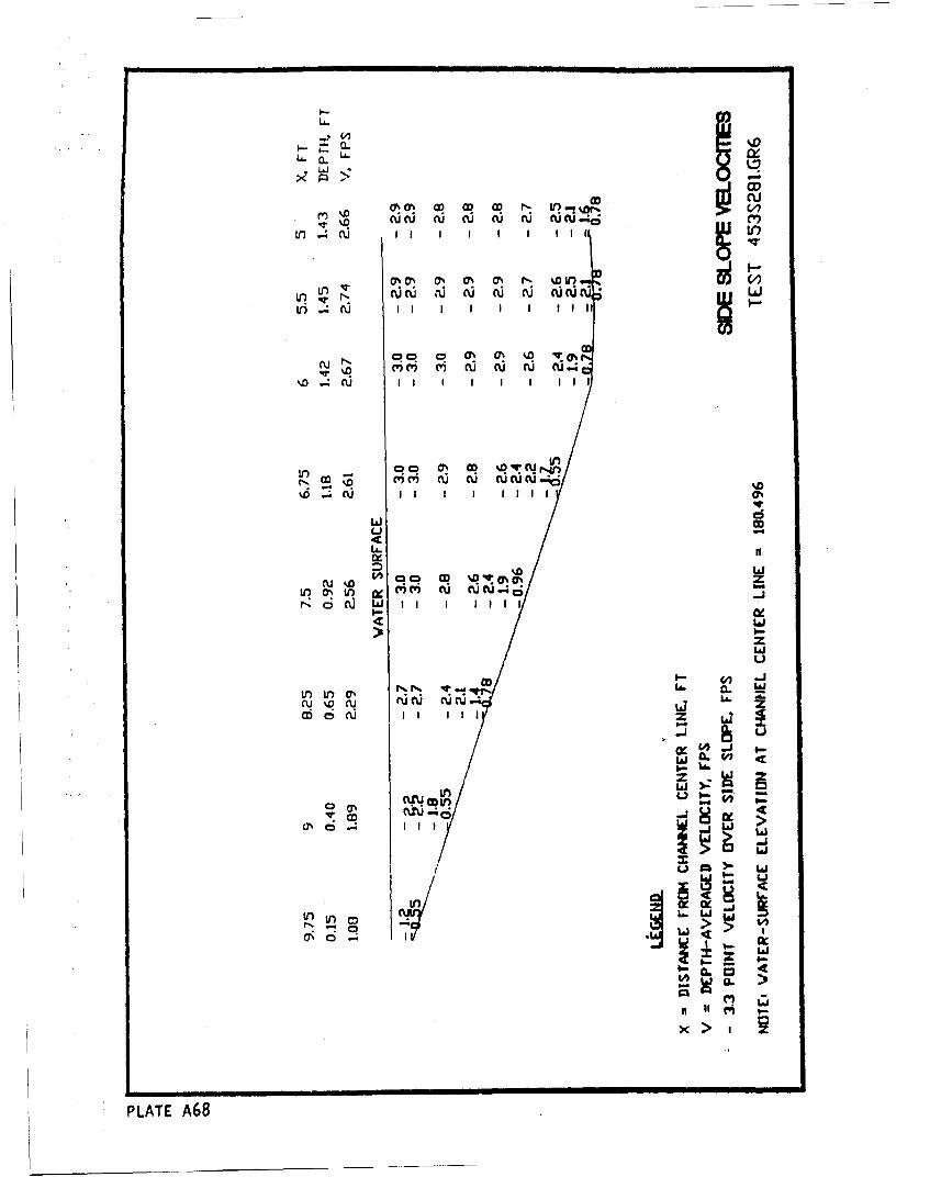
LA. LAU.LA, . CL J I
L u I I I I I I tII l L
(~N 00 oN IS % 0 r %D W
%D .- i ri rir ri ( i L
CU C'ý' n.II .I Iu I I%
LinLi) -ý ? uN
oCU -Z z~If lin NWI4
(U LJ I I
Nu %Q N ru cu CQnJ. ,ý La.A.00 n. o U I I I II LaX
rk4 .4 i c
InwII.I I!!>w
wa
PLATE A68
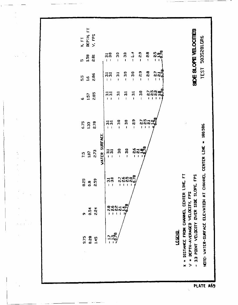
a. %0~
~ieicicOnr uc WW
in o4 cu I 1
LI -)
0 CD N
1r ) . 4 f L aJ Ii I I III
Li
N In q r% l
cum ou CCC' ?%U((U z
-JJ
& -I
C4
w ). )nU cI.
CDPLATEJA-d
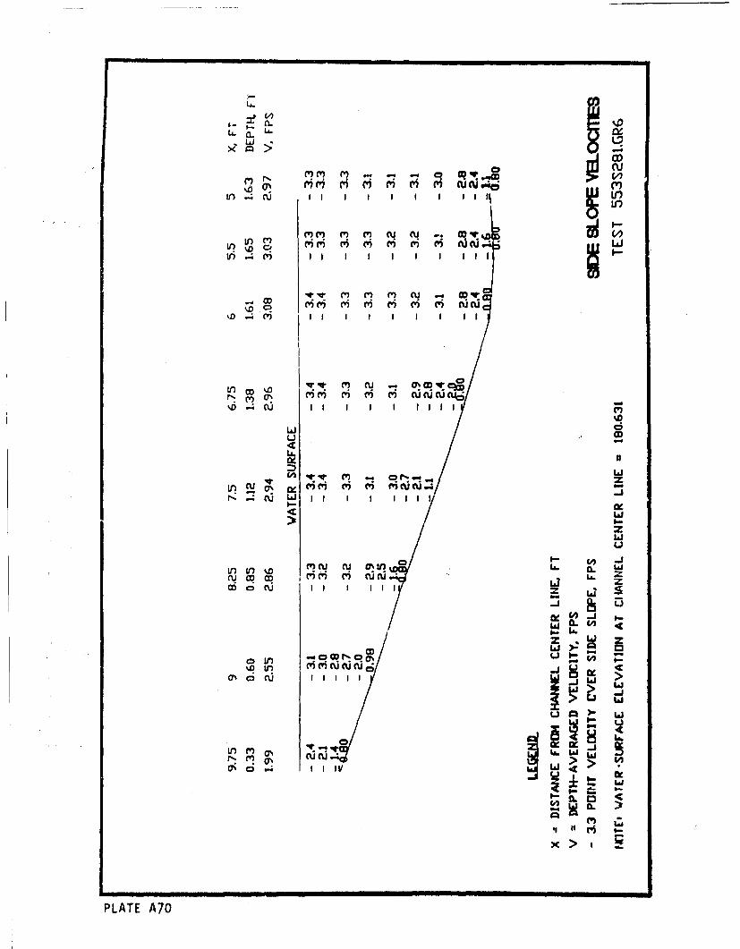
a -. LA. ~ e ~ ~
~wcucu
InD .-. c') I I I I I I I I I r
q C(') C' U u - m
C'? cl cl cy UCU
%D C)I I I tI l I I
LiJC.CD
C') (') IXC(U. 6m 6 v -w
c- L~( ~ i I I 1 1
Lai
In (r D mc u VnU L Li-
Li zi
0- L6
C'IDUCu D% Li. Ii
a cu I II I I I z
I-li-
0 U, 'i('CU~u~d .
iuI 0
0' a .4 1 1 IV A C
x >
PLATE A70
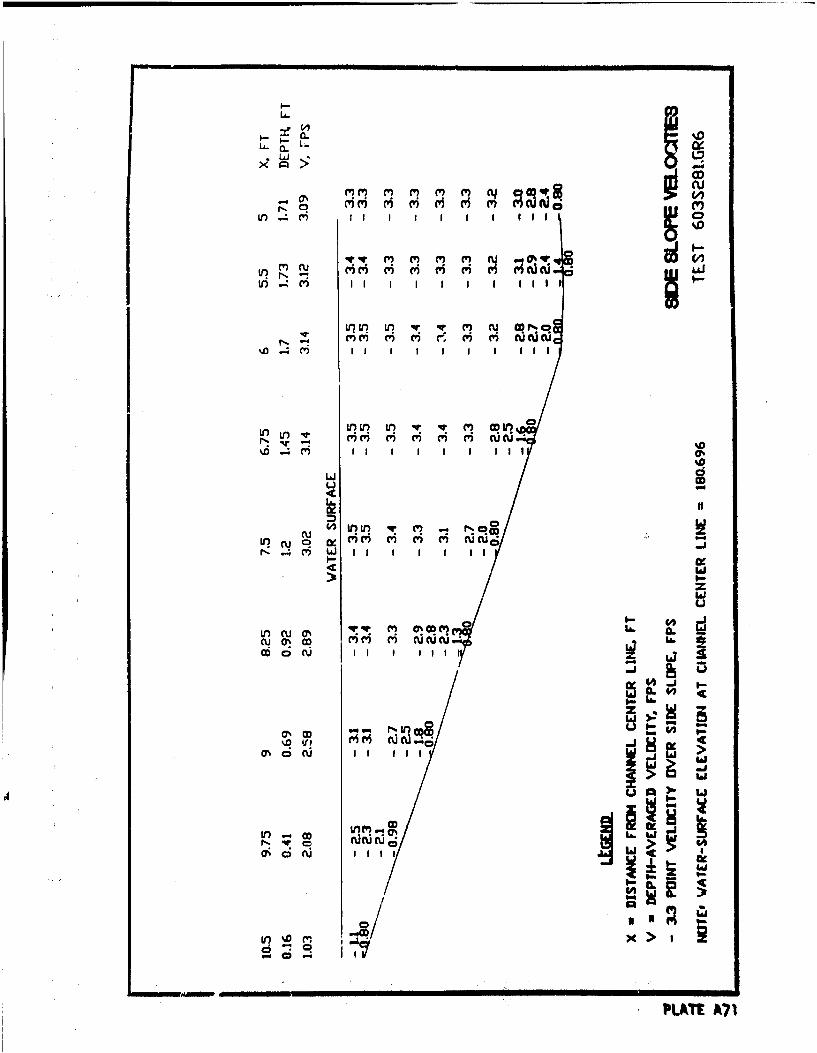
LA.
m I I I I I I I lI I I
Ifu f C' D
I i i 6 ri Ii II
0w
L~ C4
a ~inU ) cu u "'o,
C D
Cii
IInj('3c A71
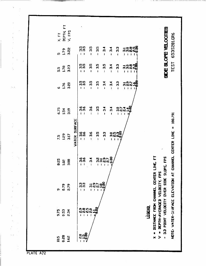
v? rin v mq
1r 4 ) I I I I I I I tIllI
LO ~ %D v~ v M
LaJ
Li i
Ix
%0C' %D Vi C - % N Ia.ltr) CD M C m r w c L'co CY) L
mU
La .
Nm ND V~) (~~cl ae
0%)CD x11 .iI IC3'
PLATE A7
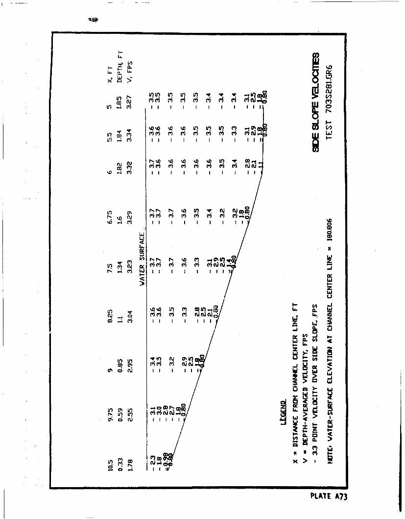
0- ý
LA. LA. NV) IQ InIn
CD cu H
LO ; m I I I I CI
tn all
%D I4 I I I 1I 4.CD
w I I I I I iIxi
w
0 1- J
W CL W W
>: >
cucu~
~ Iigw
>Lt ?
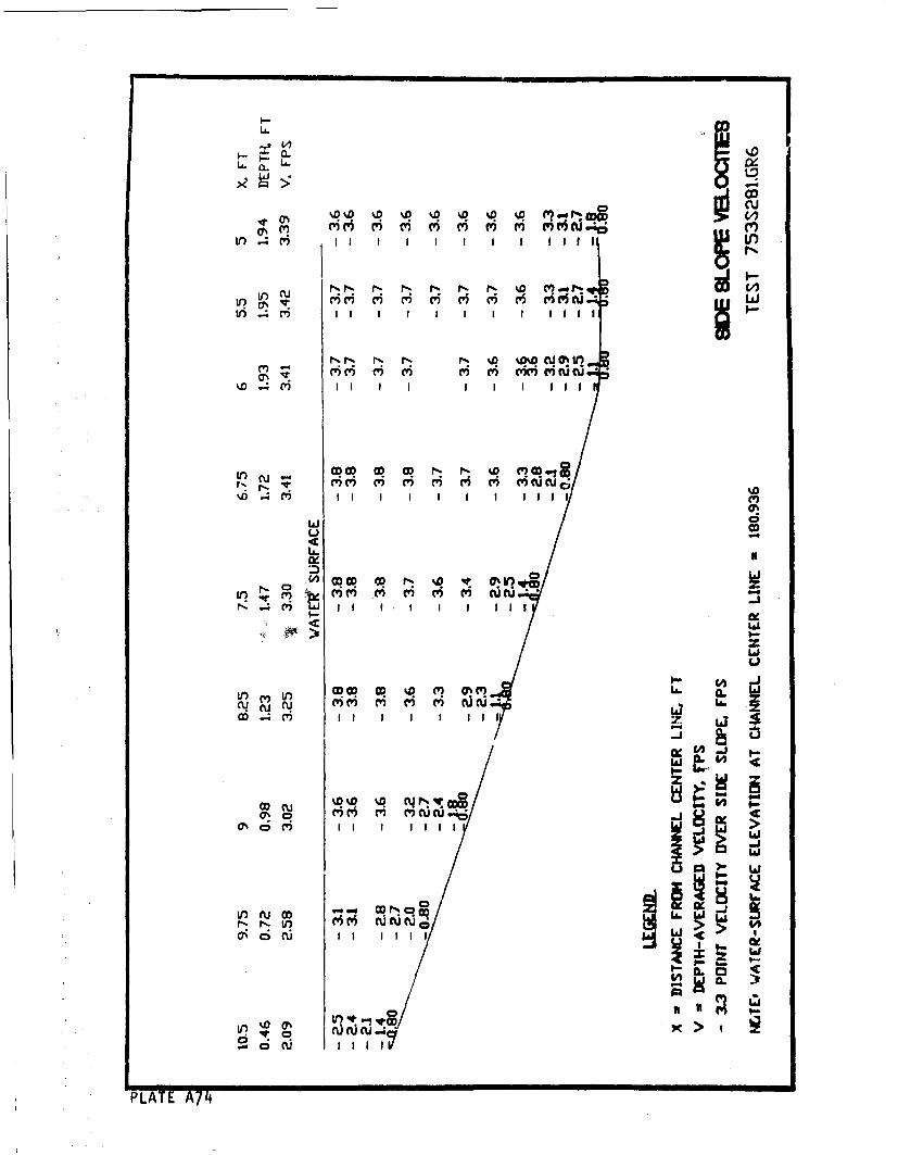
LA. ILAJ
V) I4CV I I I I 1 1
tr 4 M I I I II I I I I III
CVN CV) m ~ m ~ m m(V uc
ii 6 6 aýci ir a u uC
C-)5
OCD OD I- ItI0IW
IA,in mm U
cu m mm m mto t-N cu* D C) C' ILi
co Z Li
w~j
CO. wo C 0C' C,) C'(UOas 6 C'i I I I I I I
Iai
1r) "'i cqU(UU u!IIi,
P'LATE A74
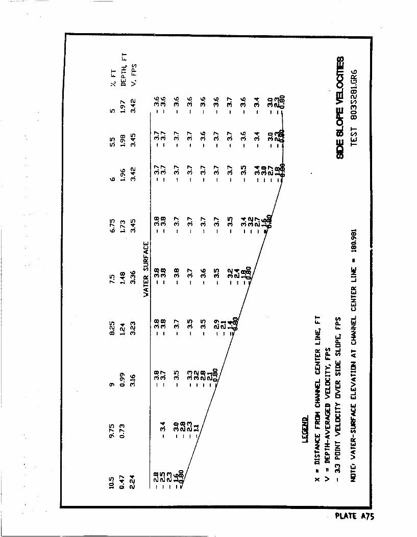
LA..
mm (v m r i m m ri
cu N N- N N- N N In VOvi 6 6 (V vi I- m iMO
Lii m i r i rs m () c
OD0 Cq C -f .0 Ifl W C V
wwa-z
>iLij
I-u00 N 1/7 ID Qq,.gLL.
LO 9LC
LA vi
(~>:CD rliW
PLTEA7
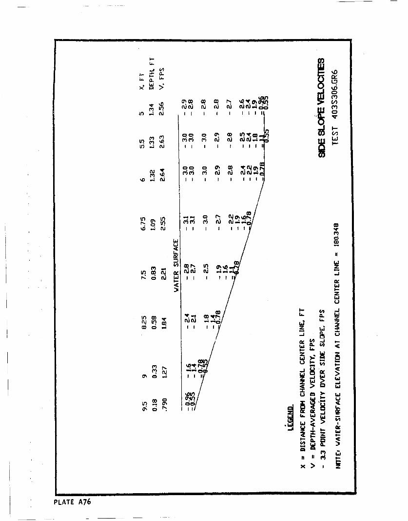
LA-CL.
L. a. U 0to CU I I I I I I I I ,
Li~n %D (w M UCUC C 4 A
V)In -(% r
0 01 OD) CU
%D I ftI
C,)ud
LA.
N cic II Ii I II
'C L6J
)w U
CDC La
La IL W LaI.- L&
0u9-
9-LLa La 3II> wi
u Liic0Ln R c00
I.'IX
n pi
PLATE A76
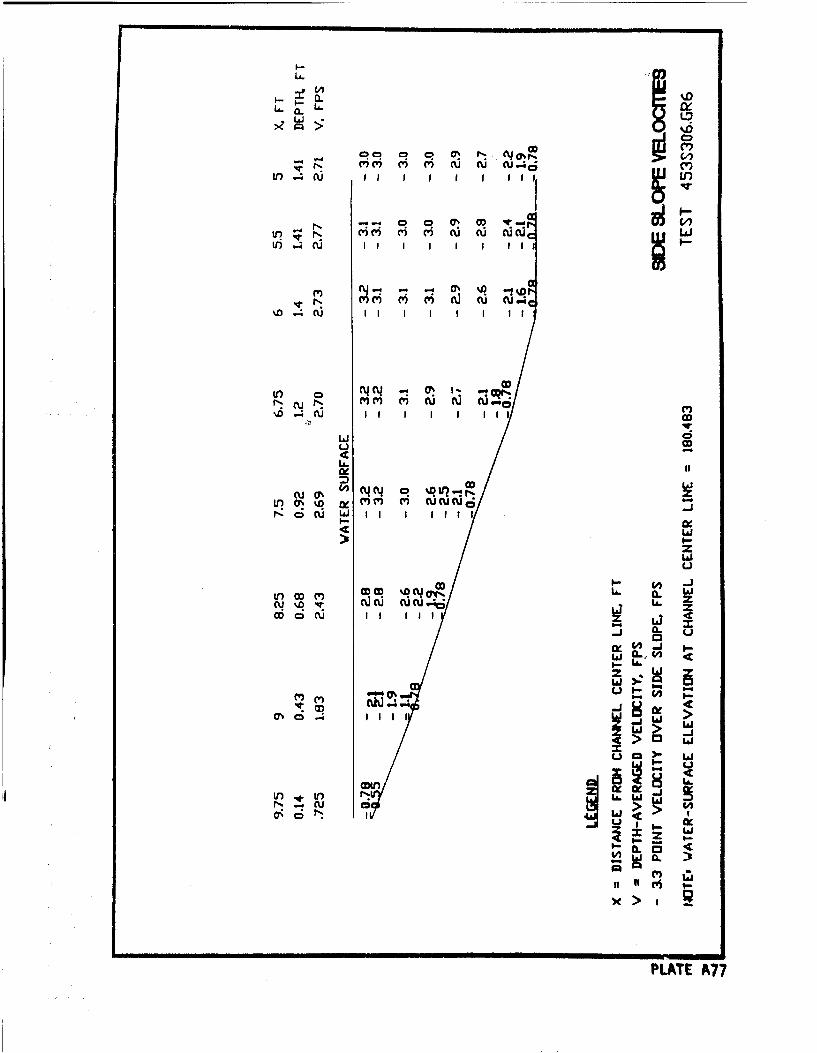
LA-
U&.
co~c mo ~ue
V I I I I I I I I I
1t) -4 -u I
%D RU II I
14.
a0 0%o lc m QVLn ~ '~ (7% ,0 I M oi ccrc
-IJ
I-&
CDI-J
CD CU I I ILIIL
-j-
w > Ll
am' Ci Ixi.
NflJ LO IJ6
IK
PLATE A77
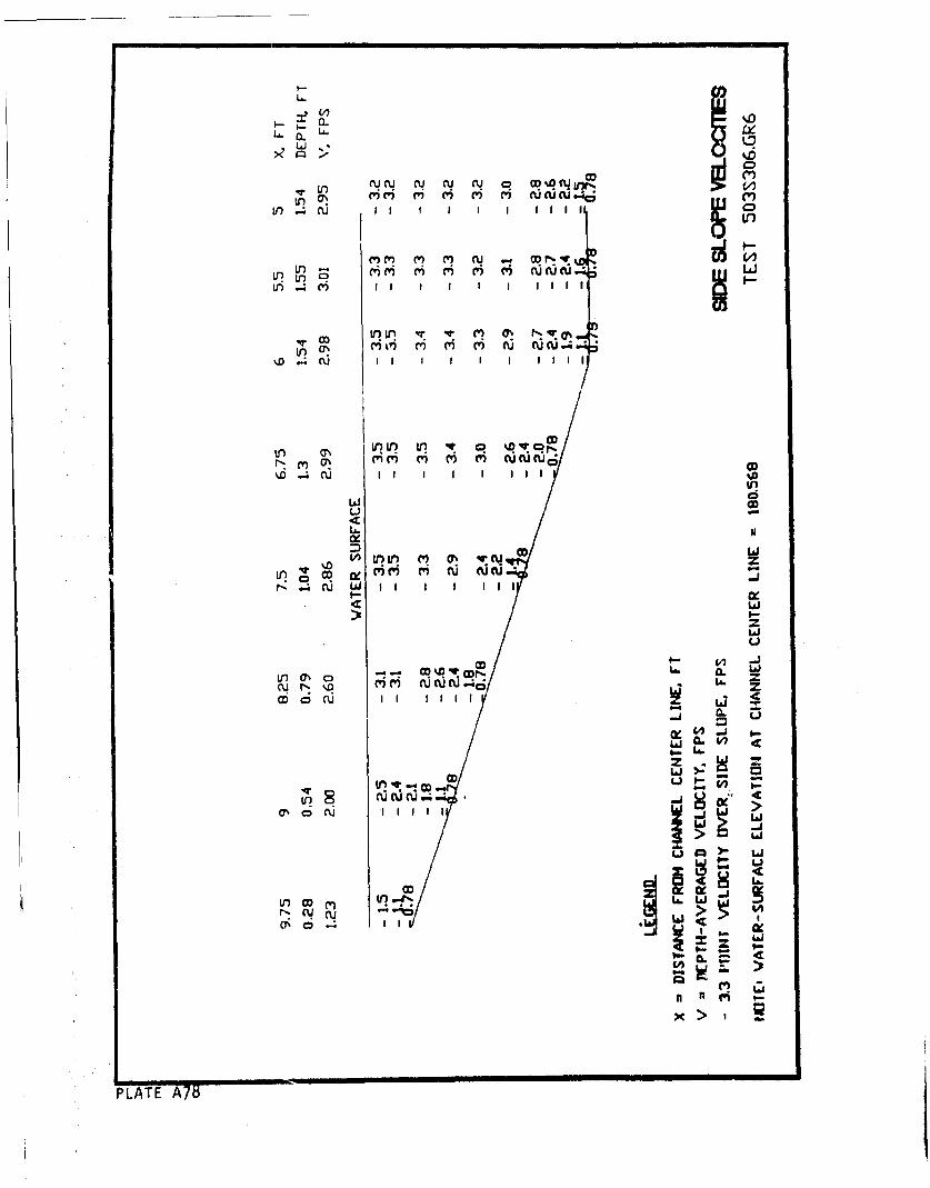
a.U0K'L Jl
LU) cu
V) bJ I I I I I
Ul VLi ": q % 'tJ
cucuc I
4
uI I I I I
7-Li
PLATE A7
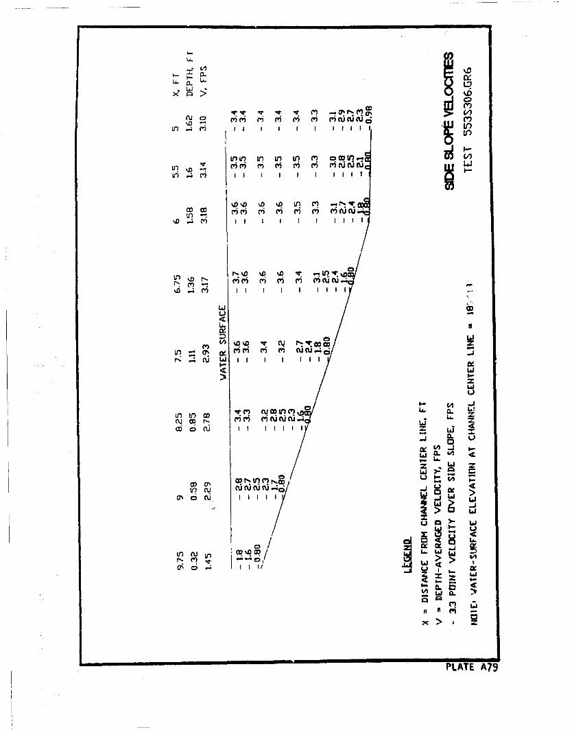
0LJ'a. '*
LL. 0 ~
v: (I Pt r a*il
V) .4C m I I I I I I I I
%D %D % 0 1)
mm m m m MAAJ
o. (4 f-lww
~ CU~tlC'~ Li.i
f-J
0.'
0z L"iz ii
>: a
Li~0/j
rII "? -T>
PLATE A79
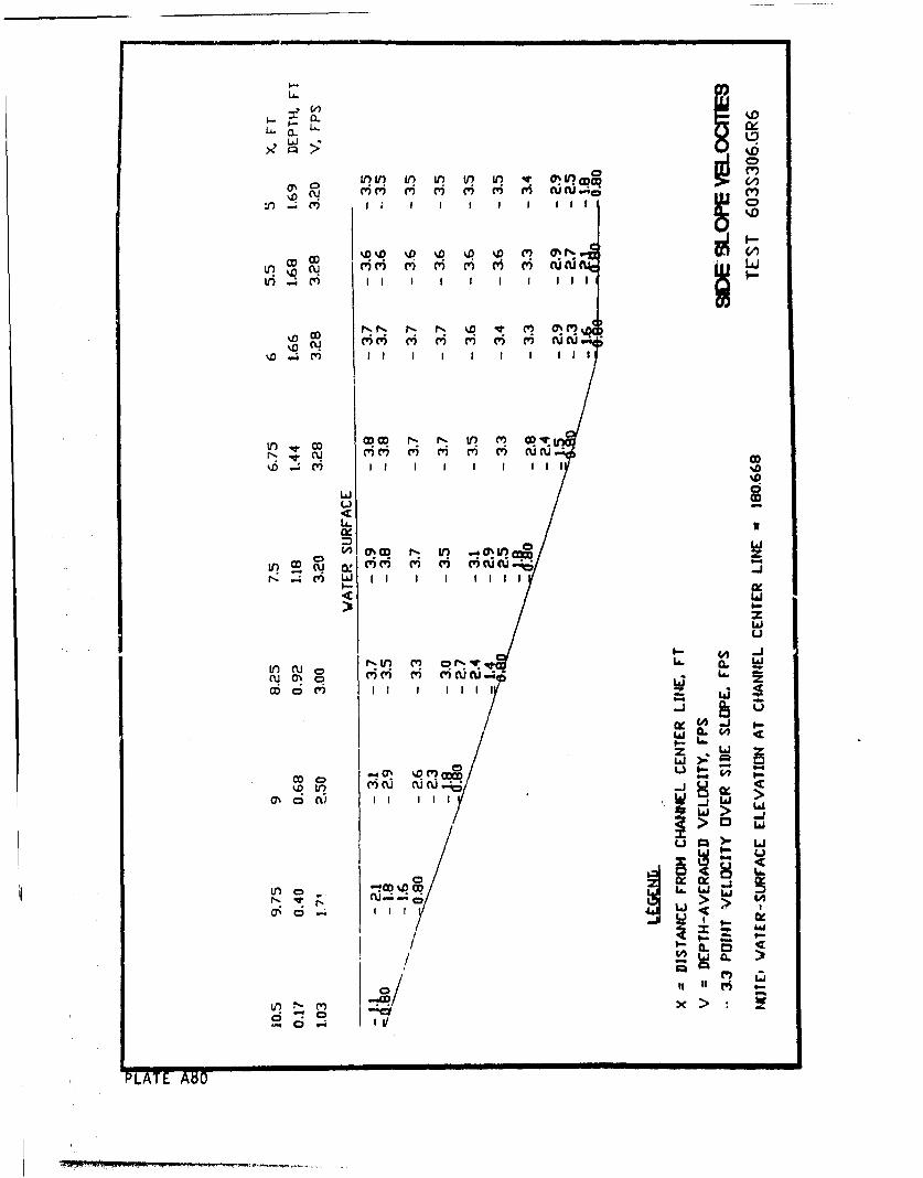
1.L U. a. htD "O CY (D' ~
OD 0m m i ri i IC A
L!r 1,D N-~ C)~
%D CD Il 0% CV I I
%D' ~ t
pI w a) I Irý v a! (5 m 6 6 j a
of
Lai
0r N U) .- OUi q-l q L . L
N.-~Lai CLI I l iz 7
V) cu c-r
u- w
~e ' I I f 111 <-at
I-
IAJ C; q
PLAT ANJ
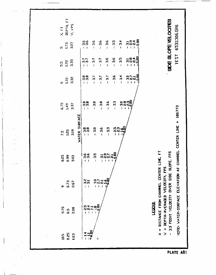
4 %6 )
00(' Cý) (0 0~ V~) 411)CU
CUC' C') C') C') C') (') U
iil Ill
U -
.4 pi w '
N ') Li 2 I> I
Mi
%0 %0 t -o
N 0 C CV) c') (W) CV vic uC 6 ZoC6~ i I I I lIi I 4 J:
0-Iz(~J2
LaJ0 >4 4
rl )CU C' C 'il: ~ .
Li
I 4
n x r' >.I
PLATE A81
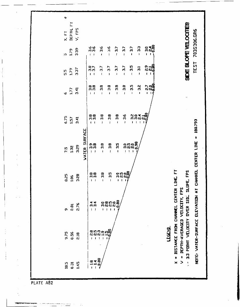
L-
r- m- M% 6- m cu=.a0 -* Mc' I ~ I' I ' CD ' ci
tr 4 i I I I I I I I I II
%. 4 ) I I I I I I I I I II
ODicOD CO CD) OD % C' J) q') 0C
LIJ C)u -o
CU UC O V 0LO 0 %L
I-J
'Cw
V) uD o co La. a
D.4 M I I I I I II z
--
W IL0
C I I lI I II
u cm
al I I I
PLATE A8
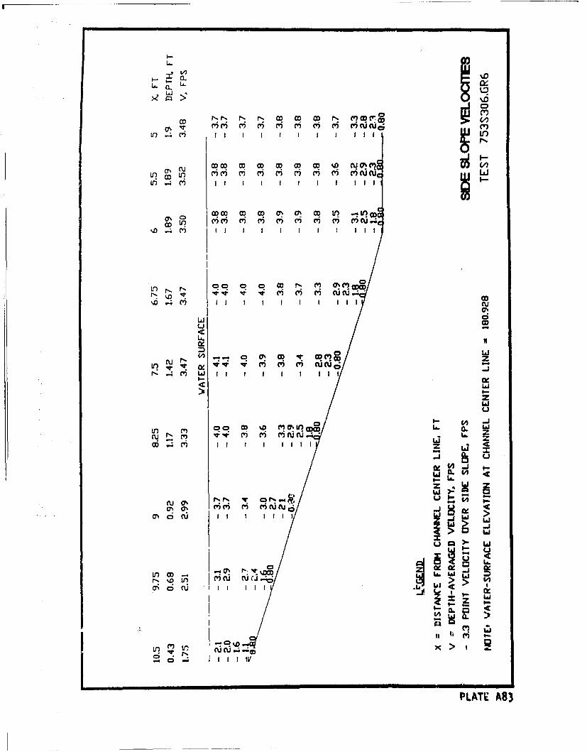
a..
II|I I I I I
a.-
LAJ9
m') ,. m m m m C') ) 6 i C ' )S") M I III
II I '•I I I I I I II '
/i o0
II ~I I I I, I IIC
ON CDCý
L I I c
LAT.A8
0 wCUN r- as% M V W( z
0! Li
Ll zL 4
u-
cu 0
~', N ~ C) ') ')Uj Li. Z
-J
p, cu cu.; "m x >
C; I IV g
PLAT A8
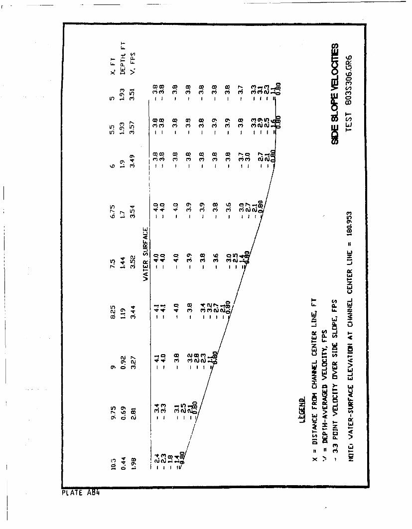
LL.
00
vi ri cu -; I I
In ) m,~ In m m% m~ m~ m~ In m wLr (1) 1' 1' 1' 'C (
in 0%0 OD D c5 ~t w
IxI
D Licu W Q)%ýC 0 OD D o V
Pý ) I I I I I I II I
4: bJ>z
In ms IS cu$j A
C'U) C')U0'W' IL Cod11
r-j TO 04 C'R' riCJ
m 0 M I I I I I I _ill
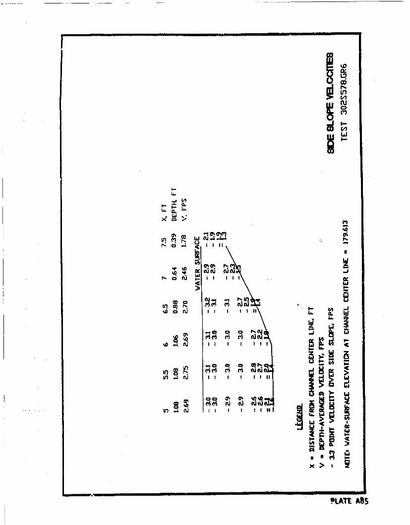
'In
L~o~J ccflu
w
CIDC 0 Ikdc i I I I I I 1 Ito a.
iir~~*At AS5Wcu
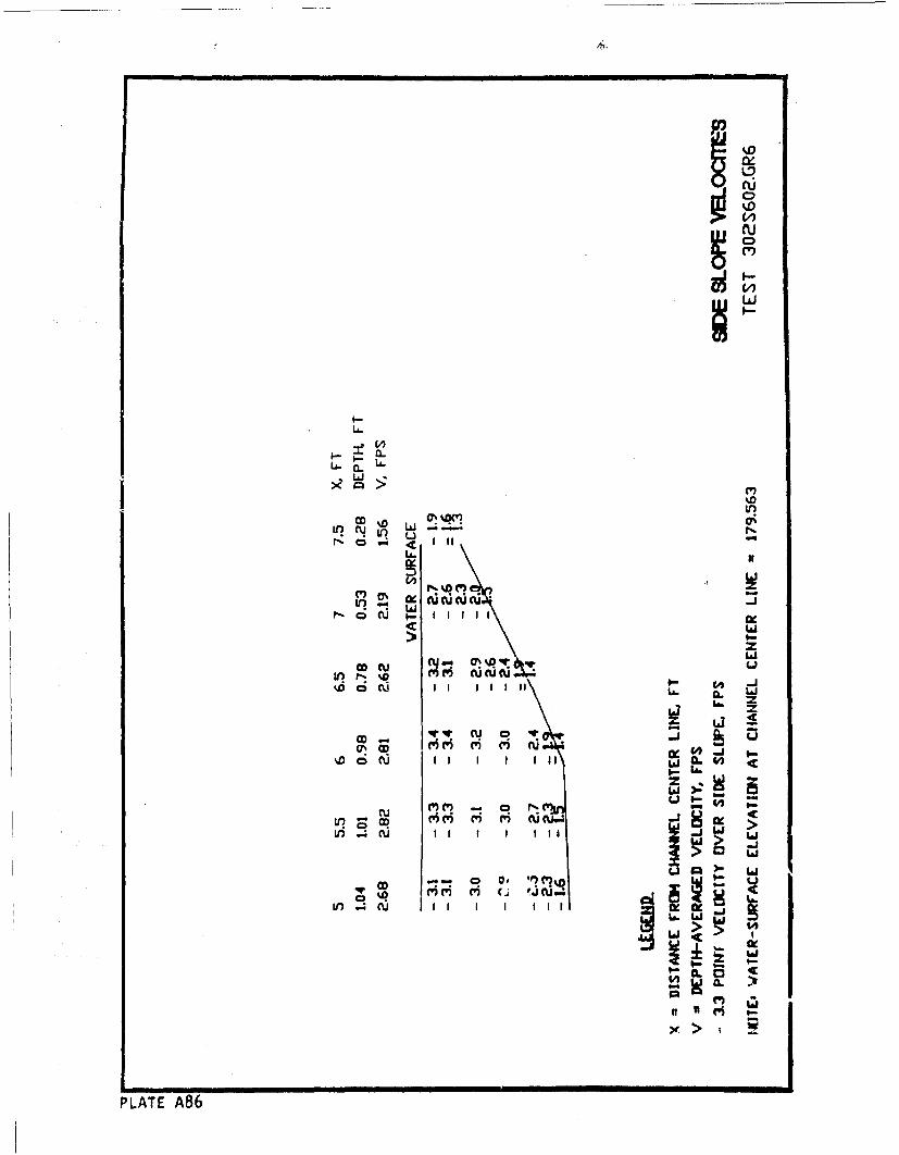
(W)
LA. I
LQ
Lr) CU
LAI>=
co cu u T
V) 0( r- %D r I ewI 9-
0'( &. r
IL!)d
II >C'
PLAT MM6
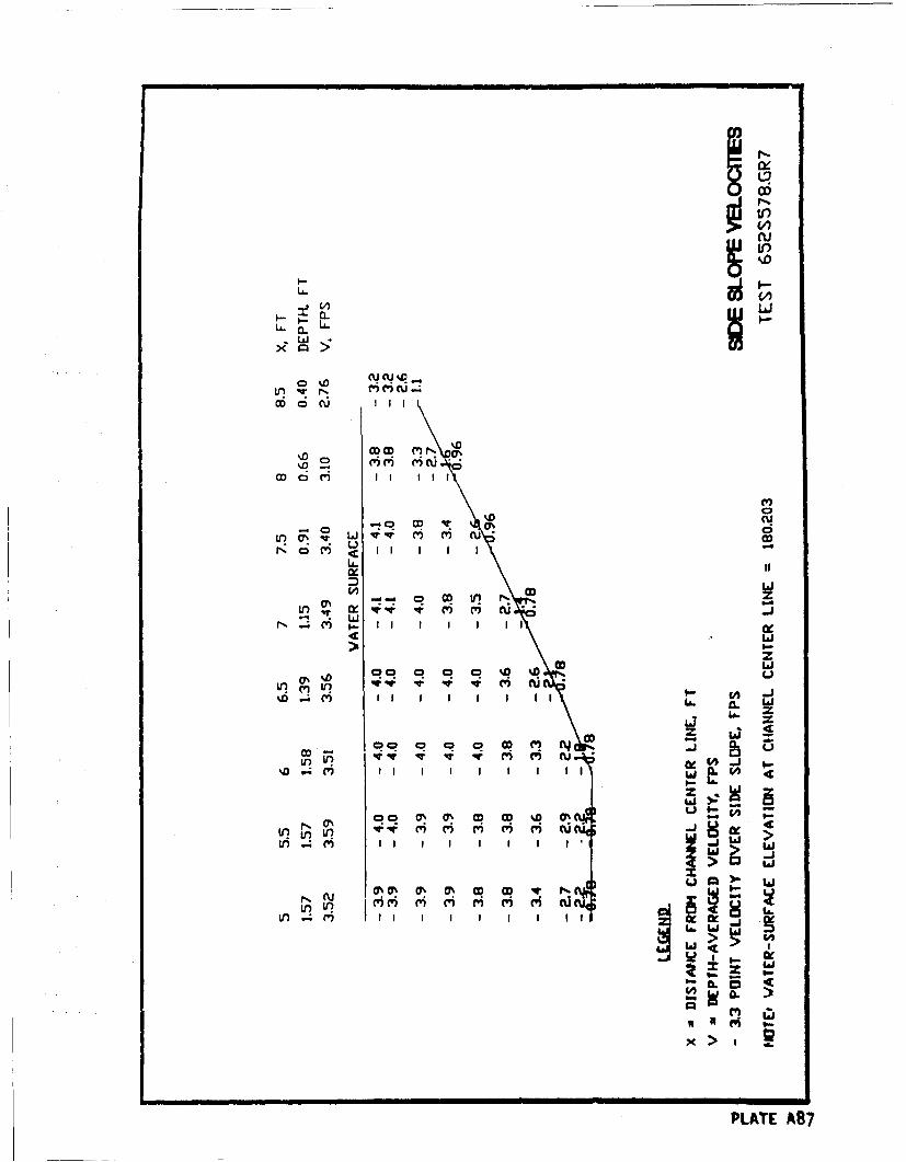
'ILj.o
LA.
Ln rl m mCU .4%
Mo C\J II I
C D M I I I II
LA.
LixIDw
LI 1J
%7D 00 00!%
LA. ZJ
z Lco v qw CV M CU-i w
Nq 0q C q (Y) (Yq (U
bi in V I I
(U 0 0% M% Cq CD 4- f,
Lo~~( W? H) H M
in~~~~~LT mA87 I I I I(Iii
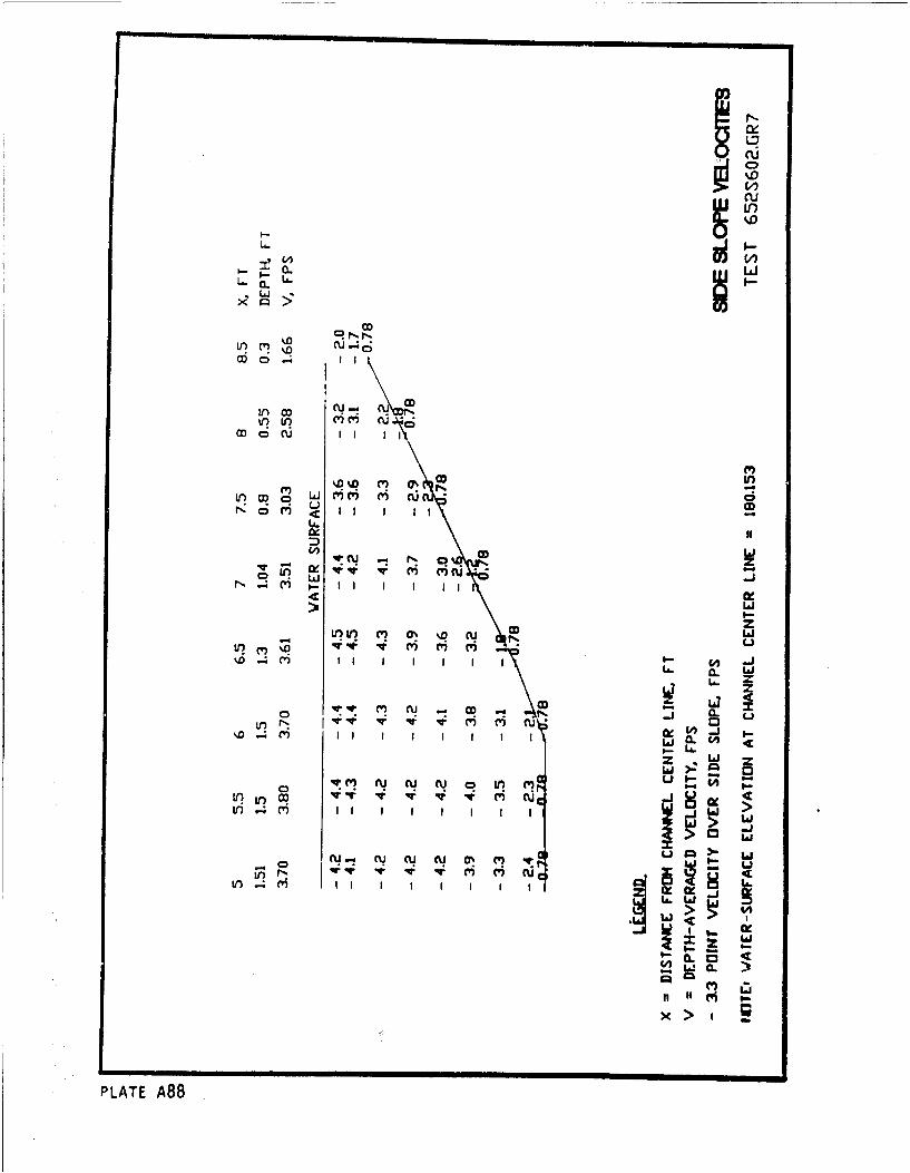
LflO~ u..4CC
U) U) ~)~cu
co%0I
Ln CD
V?~Ol C'7 m c
N ii IW I I I I I- C4 D
Cz w
o LA -j
CD w
-co
0,-( M l -J I.-
II LL16t
PLAT A8
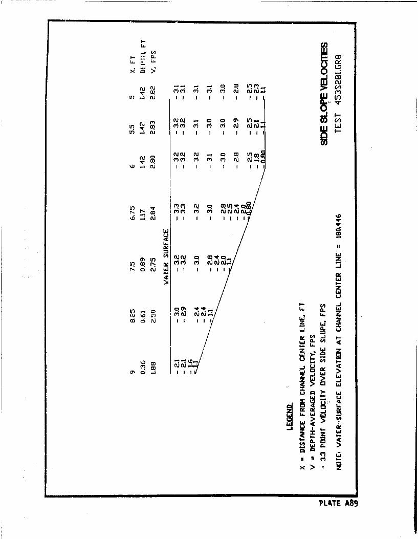
LJi
00
C-C,
SCCU q zq(tr .c'c' c' IU(I(I.I 3 O
ir) u L I I I I I I
ui CD
1 jL£ co
m t CCUU U0 wvLOCDpý (qM c c I_
C4 -J
V)I!U . *cu % 1r m Ci c cPLL.T A8
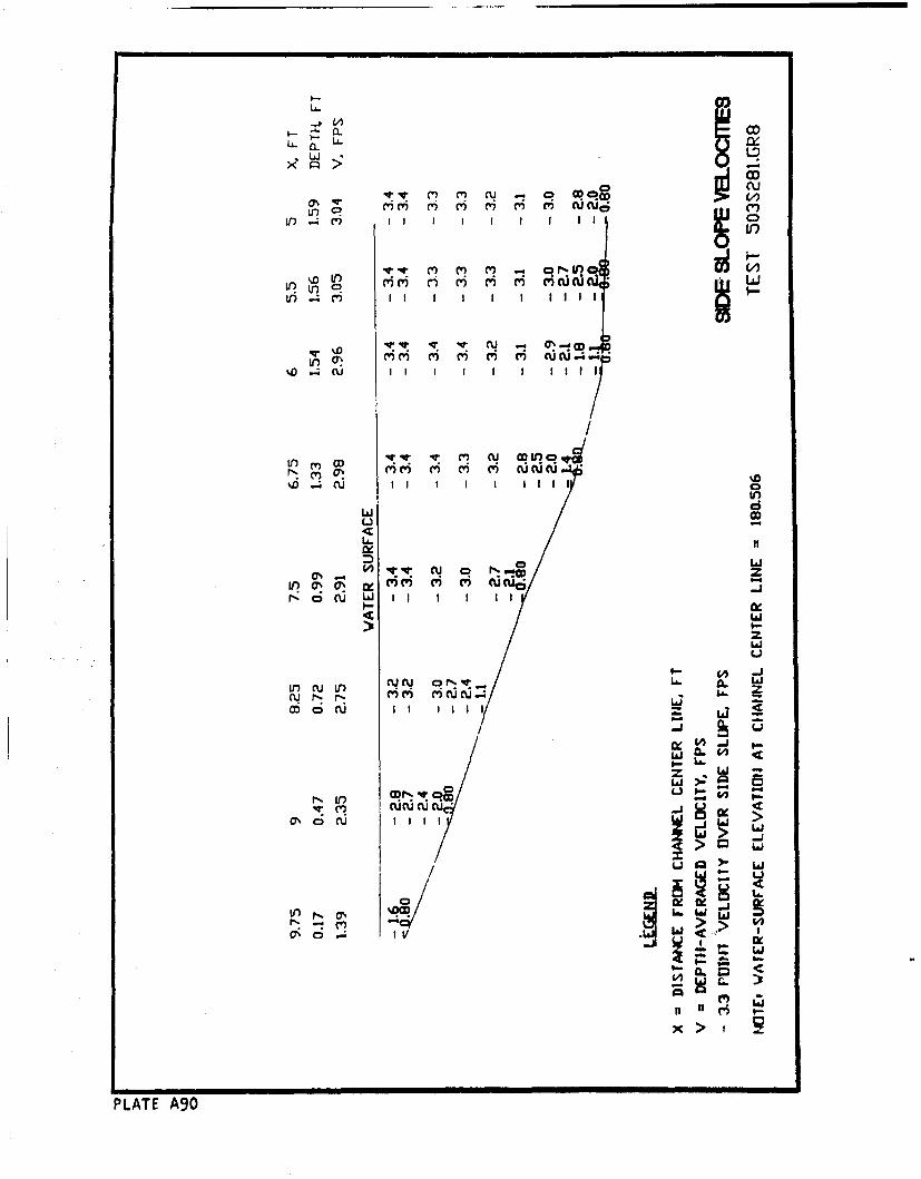
CL-cLA- . A
LO, .- cl)I I I I CD
L L r~C) MI m I I I i
to ~ q ~ m ~ r) n ur r cu~V) .4 CV II I I 1 1 1 1 1l
4W 1) COJ CDflV
%D .u I I I I I lI i I0 CD)
L6.
M Lai
Ln %- OS w C- CUi 0 r%..C436
r-: 0 LaJi w I I I I I
L L ) LA -
z W
V i cu cu cu % Li. _j
a*,oýCU I I 1 1a:
La.
LaJ
0 C
0I P L T A 9
xI- I R
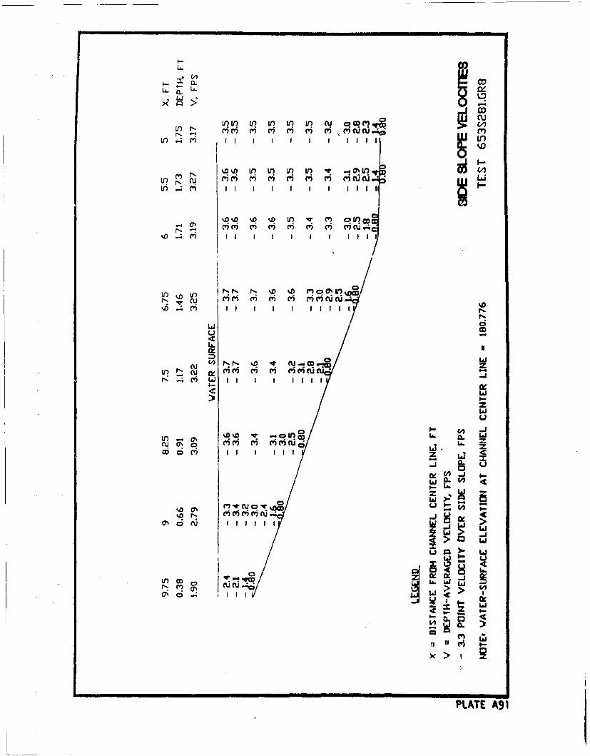
LA-
U- (
In In- (4In C
M% 00 0n In 0t -OU
% .4 M I I I I I I I I I I Nii
%L U ~ C'lt
LA) CD 1 1
u~ CDIc
0ý0M 'C' CD C" Cl't
M LL) I I I I lII II
C4 JM VCDLL. L LI-
m CV m () (w tu i LAco ri f I
0~C U '~
0
U I--%D r, mmmem'~Ccu J c
u in
~Lo~d~ i0
PLATE A91
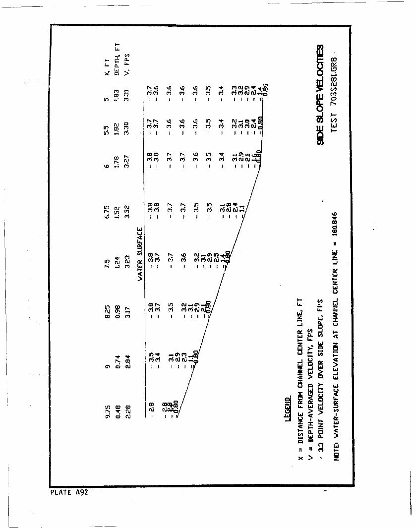
LA.
C~LA UDa. m , 1
LIJ L? I 11
M- CU (CYi C6 6 H(m (Y) (WJJ
V)(Y CY) C) ' ' C)JU-
iI) I I I I l i
CO P, a? qQ W? -! -
CD N % C-
LO CU CU )i C C) 'uu
w ri
Wo ' (i M i M c, i
0-
z W
C'C' C'CDJ r
x I i
PLATE A9
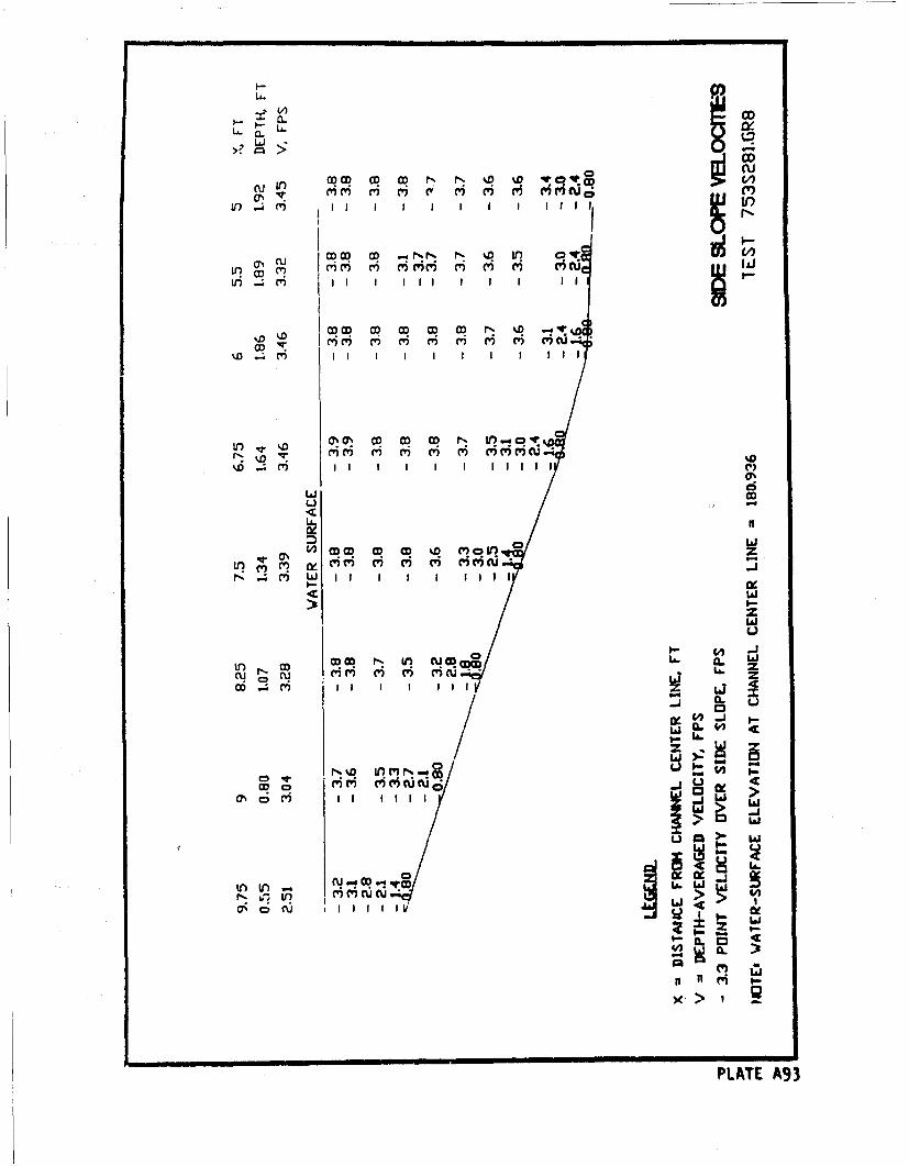
L46
WUJ
e'c'c' Lr 0 ' 'C
ON H i ii ty i H ii r
m cu I I 21
%D M IfI.IoI
'D riI I I I I I 1I 1I I I
Li CD
cm W
6 zco 1 1 1 L I 40-
Lj . W
>-
M ~ ~ I C: 111 II
zw
CU -4 OD-in ctj -6jL.L
PLATE A93
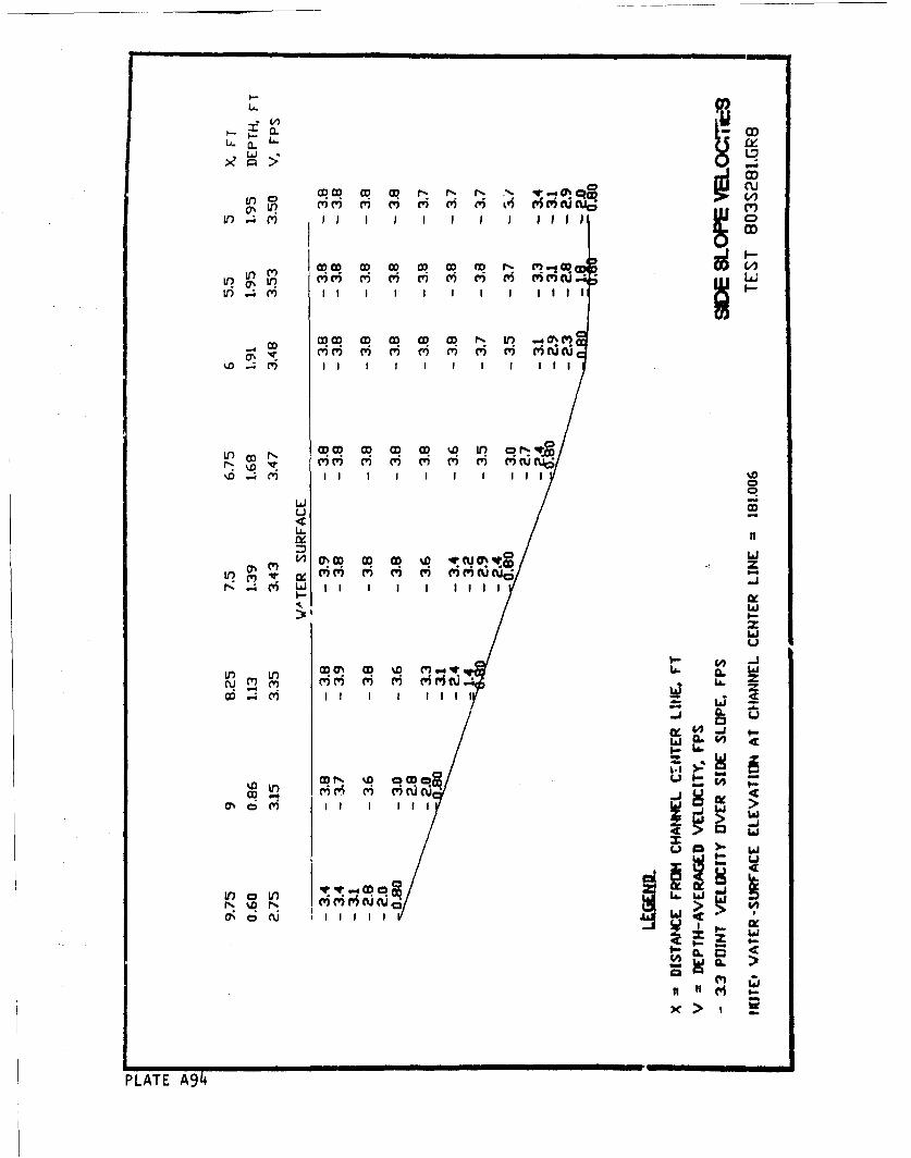
CI-I
V' 0 0
V) P.; I I I CD I l i
C' U') mm m ) m' m' m' C')C')CUAJtrrco~N f .4
Cý lw' ' ' ' C 'c c%D (V5I i g I
LO Co N W N .0 IC')C' 0' V, vi) C C') C %16CU
040
.i. . O
I-x
L&J
>1 :
CD~I r* D cC
M I I I I 11 w-Ji
In If) wN'D 0 a
N'0 NQ
'1111x
PLAT A94(
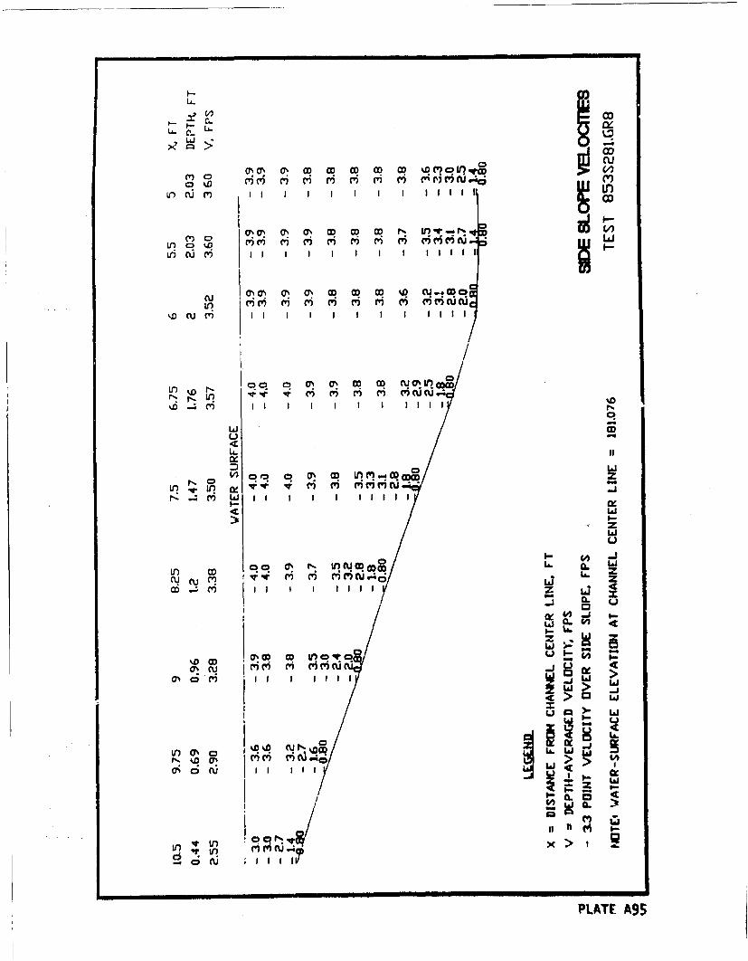
U-
m oO co a~C~ ) CD I'D CD W V)PJ
Ul(CJ " cu I I I I I I I I I
%D0 CU M% I I I rII % If -f I1 I I
4'c~ 4 ' 4 ' 6 C' M , c u ,c' c'u5i*ii
II ý R L! (I Oq l
> II
zw
0u
I-
%D C O CD Lr) W CJý
a! C C'i' M ' H mmf~u0%0C) ) II -j li>
OOCU% %D CU .Zi6 H W.40 IIII>Li o9
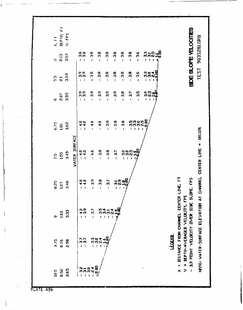
rLC
Gs 00w w~ w w~ 0 ovCr) C 0!"C) ')~ ) C') C' ') cci
tn~. cý cý a , in qIn
w mI I I I I I I I il
00 o 0 0% M OMfl'al'*~~~~~ M (V C(' ) 'C)cu6
LA. If t t
cix
o Li0%0 CO O N N CD *) 0z
u L i I I I I I l l
4:1
LaC.)
In~C3 r- *'.1) ' ' '
CD .mI I I I I I I I
UI I.-
C)i
0 >.
(~oflJ II IIJ~ c1w.-> W
/Inu
LAT %DODL&6L
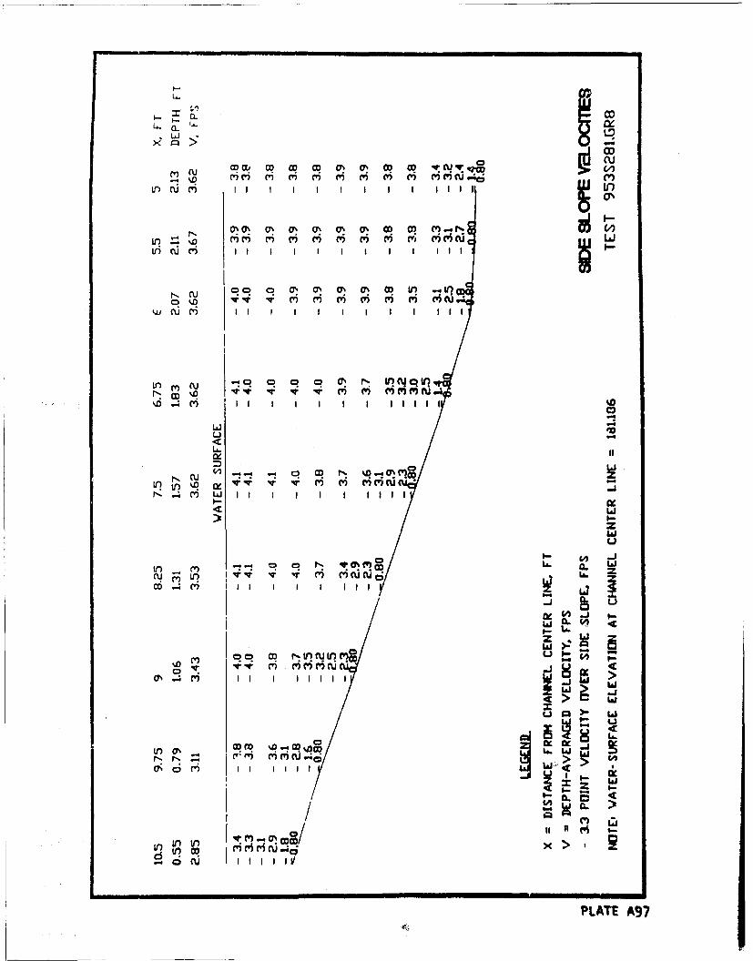
U.
%q t- 6 6 W mc ;
LO iri (W) I I I LOii
CUD q C'ý C') C') C') C) C) )
cu mC I I I I I I I I I II I
in CU q a? C , I- I Yc i
% 4 mI I I I I I I I I I1
Lki G-
CU (. - - CD N %D...0 C'?tr) m~~~rC)C' 'C)~
z
N- (r, Vv I T M V uc
L16
u in
W.- C' M LII I I I wI
0 I&j
Cl) Pi0i-%
o0 II II
PLATE A97
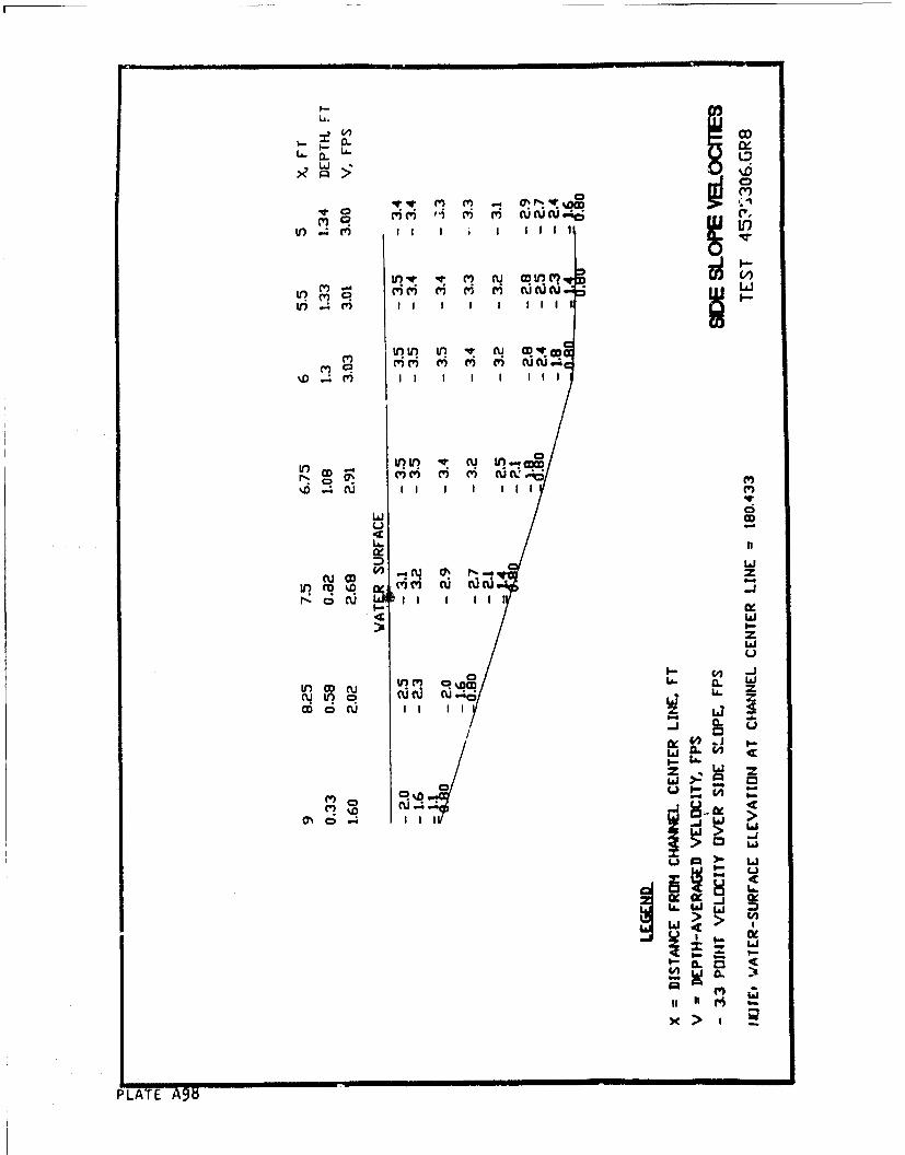
UA.
U ' o(L C~C'
Ul) .4 (Y) I I I I
C') (T) C' M () N cu..
('C' W? ) W') mm~
.4 cu I I I I I I
Li 2
Lim Nt %Q1
(V) m
r.- oc CU II I I I
z
Ln O c * -Y C A C ) L IJ
CD c U I I I I-J
79-
IID
CD kDON1.
4J
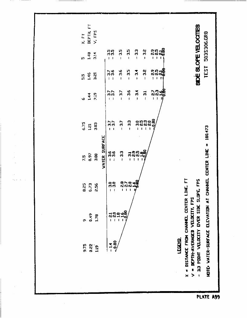
LA. a.LA.mL&J
V) In~ LO~ I r (I IY 0I l 0
?Ln: 4.0 CDfl Q
LJ* .-4 () I I I I I I I
NN, P ) MMNc a
rir' cu m~UU~
c w I II I I 1 111ne<a
L) .44w
a N
4 L&
1- 4 -
LflC)La >:M\ "i R( C'C' CUO(
nI c III,--j>
os-
-WC-OSCU~ +
CL 0
PLATE A99
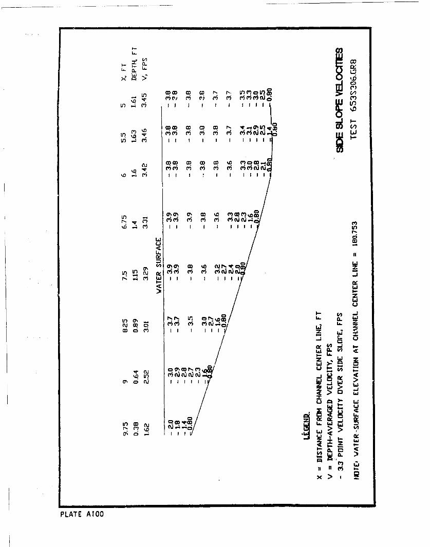
0- c
La.O
jfC)
V) W D OD CO r, r- Lr w) CVIIC
%D CD %
U) Y I I I I I I l i
U, - q rcQ q' cq c'Q %Q v q
1D i- I I II I I I I
ui C)
ixiV% ON a D %D c. Nzr l
if)eu VC' ' U C'm t) C')CC Wf .4 ') I I I I lII II
zLi
Do M I I I lIl 1 17-C-
cc
U0
lwC' cur.0~~~~I CDCU I If 0c
PLAT AIG>
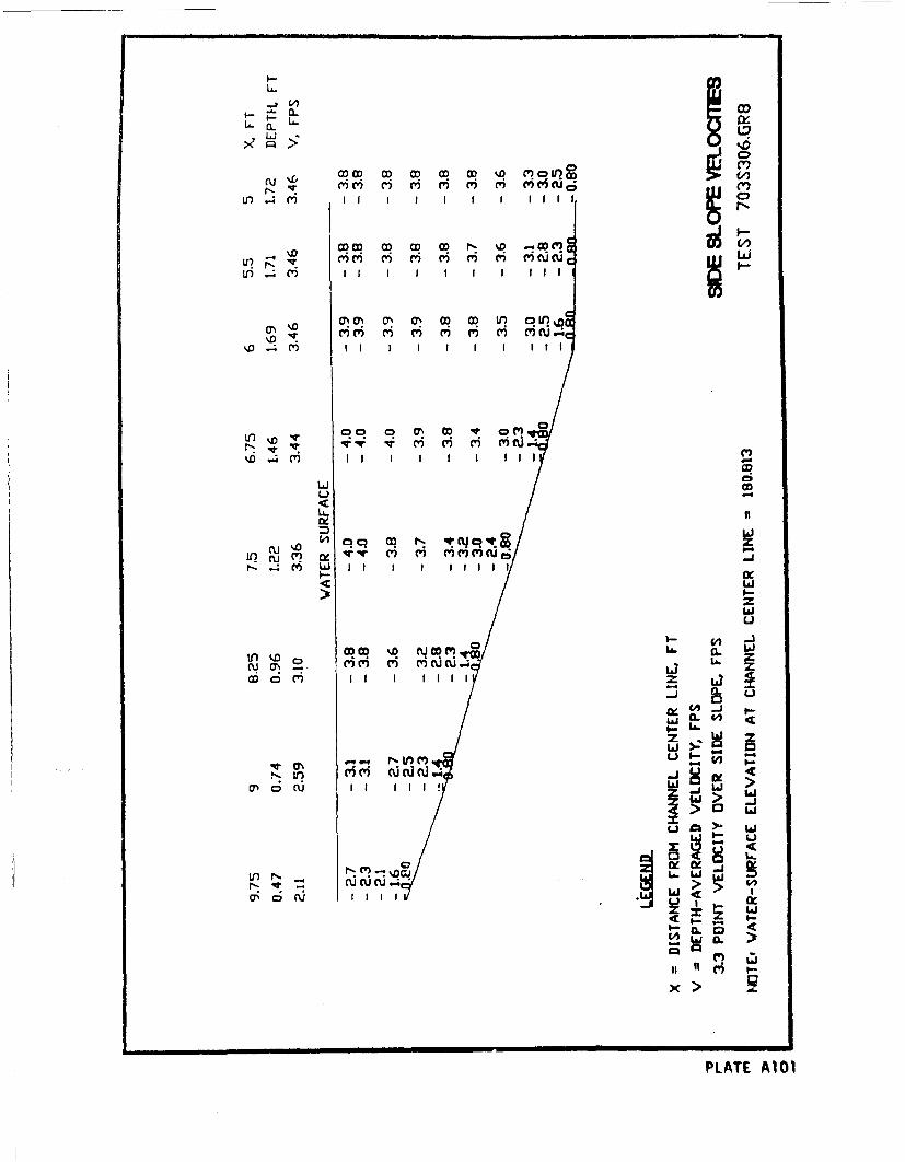
V)
Lso>-
f) .4 (w) lI I I C)l
u'? F-~' ' '~ ~ ci ciu
V) ) I I I I I I I II I
%D .~ ' I I I I I I I I I-
II
(Ld c C NU~u' ~ C) C' 'CW()U
C5 CR r~t t cqq --,r) u CV 'TW M M M C Ci-j
Ln cq 0z OL)
zr-u~cw
NO
ONI
NI V)'5 1
PLT0A~
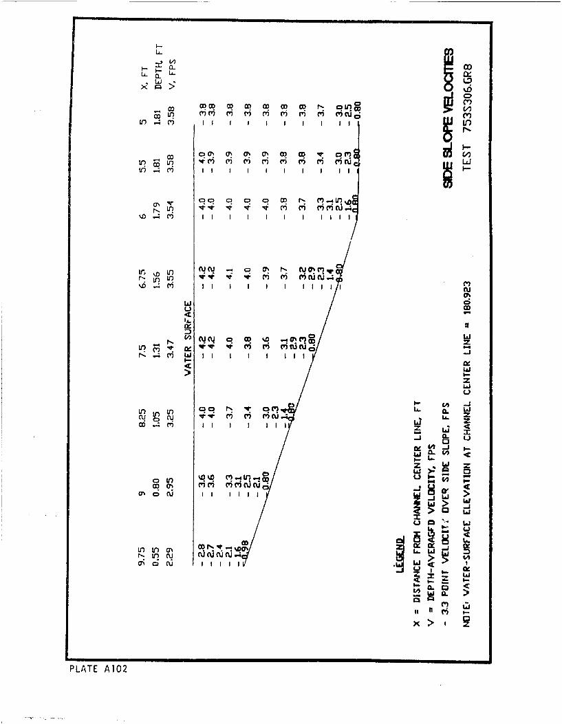
U-I I I II
00 0 . .ý.NV? L? '
co JC - CD 0 UO
If ; mI I I I I I 1 1
ON V
N N Oý~ - CU 0 (n
r- .l II W i i I I I
9--
(1)J
I.--zz
1C-)
CN CU I I I II I II L
I-
Li~o.C#, i
0 o CU I I I I W
c7~o1 1111
x >
PLATE A10
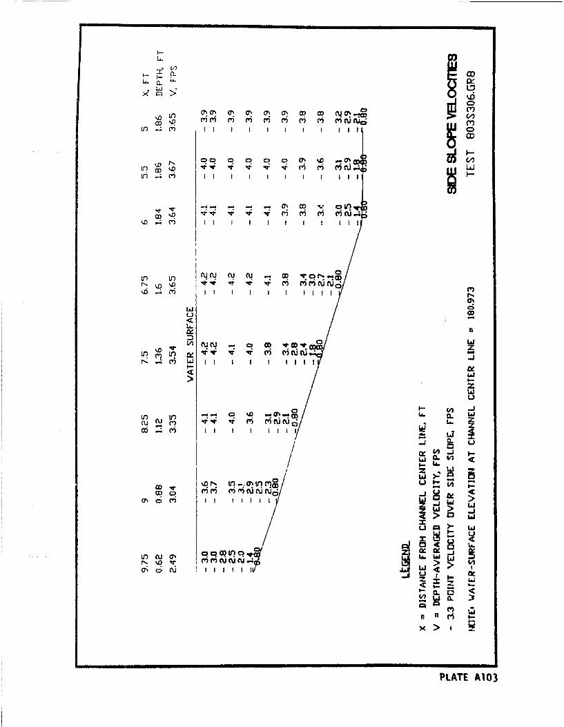
CILLZ
C00 0' 0 0 0 M ý.oV
LO ) I I II I I I I I II C
LOIqIl I I I I I I I
II I .q It v Ik m M N I
NI N CD V CID It m
!-- cv) L I II I I I I IlIS
> tI-z
Ci
V*) Lo coo U. CL
u mC mi m fu1 -' c
-J -
LJ> 0. 4
LL-
w li 810
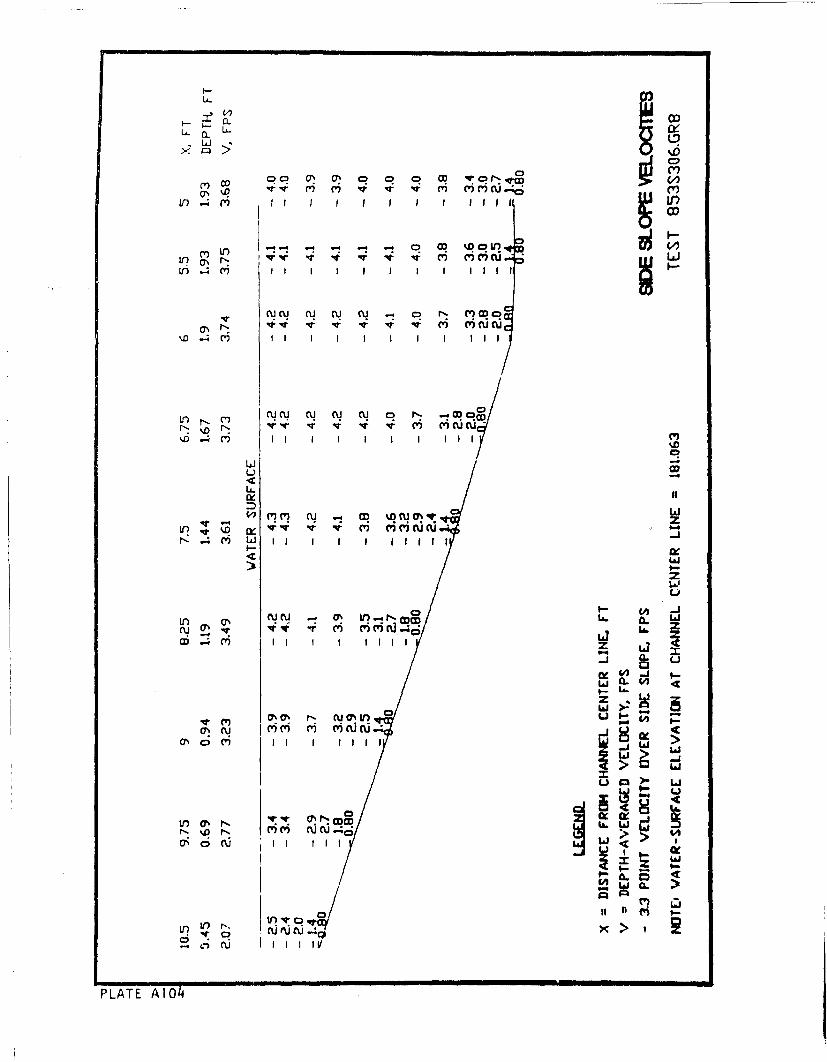
U-
~LJ - hx9 9= %D 9 91
CO oC:) OJ (7 C) 0. 0 co C') r
U) 4 mI II I I I I I I 9 I99i
1 v-tv v 1 C) mmNLLr? (, r L)
m mwcw
LAJi
o 9-
W CV) L I I Z L
0A -.
CD CY
L CL. ) -C
- V. ) Cu cu0 I nI
PLAT M MOCJr
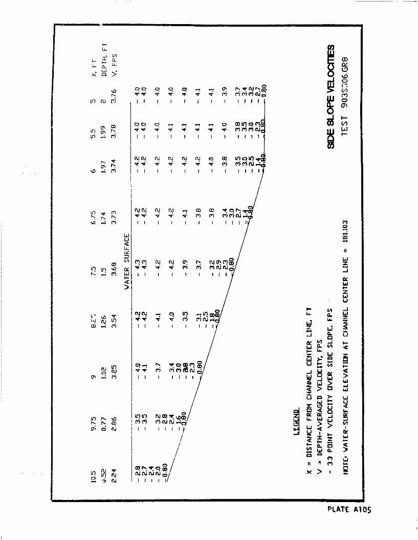
CU!%D C0 0 0 - - Q
0 rt 17 1 ~ 17 17 CD
ON 00 q C? q C If? CO('
v I IT v V V V V MiilC L
Nq N NLI NU N C q CD or C) r
L7 Mr Oq (1 N NC O ' T qq c I '))
% 4 MI I I I III I I I I liii
Li FD Ili
Li5 -
UJ
4w
fu Lii V, IV L I il
C' M .--
'di
10 IfuI
US .4 I II >4
&CI1J I-4> M
z LJ u
C3 'tc C L-In NV) U CUOD VOCD0: c: (
%D LA.
ow Cinn r% 7
in in. cW C~ u5 cl I I I I'
PLATE A105
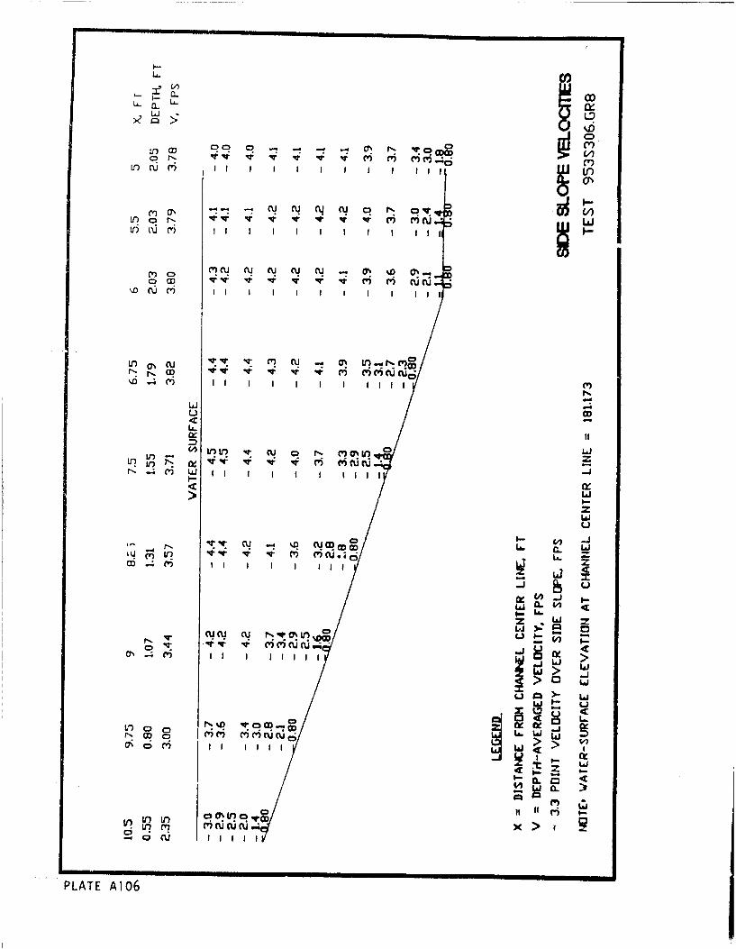
CI,'Ia
CU. 04
oc~~ 00~ 0LfCV) c5 Iý ii
Lfl-W I II I I I I I I I I II
U-4
.4 cu) 0L
WI 02 II I l
U')
N ~ -i cu N v~ 0%t ) vC) V.4 vi vic u
> _j
W9
0L
tnC' C3-wLI). 0 in co. ,
0 UI('I I I XI
PLATE A106
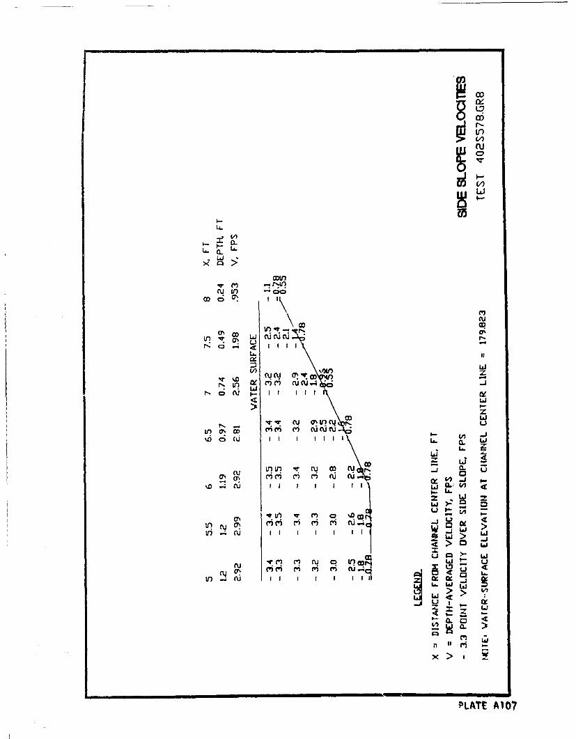
Li.i
LL.
U-~ a.II II
Loi
Ln otIn- LJ$ucuc
0ý -
0n ~ r -J cu ONI(') w' ri pi CU..
L9-
'-LI.
j~ >
a) tu Li 4
Lý KU.1 4>
cuA~ MM(O?
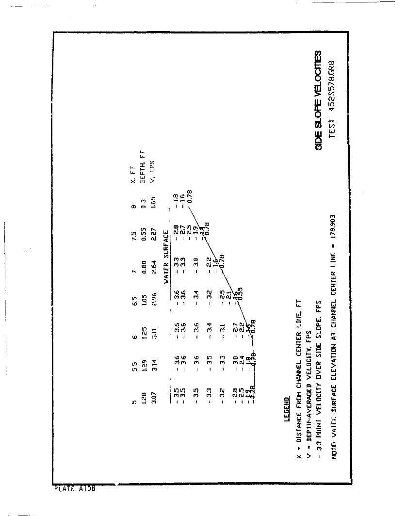
'o
0
La..
LAi
C-)
4 L
(I-
Nf L C3 U IC I I I I I Ia ~ LLL.a
%D'a %Q U) CoI I I WI:
44
%D -4 CUa. )Jz:
I! C' ,
PLAT I-I O 0
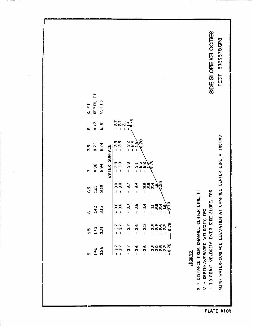
C6
I--
a.J
LfLi
CD Lai
CD CU I II I DIIIl l
LnLi
C)I-j
iii
CLN La i
IOD i; S I
CC C N s.D VA OJOq%'OU,) r'C'i m- Cl- r ()i c uic3~n
NN N%~O 1JW L~ 0. V
Lii
m rw airi j PLA TEAO
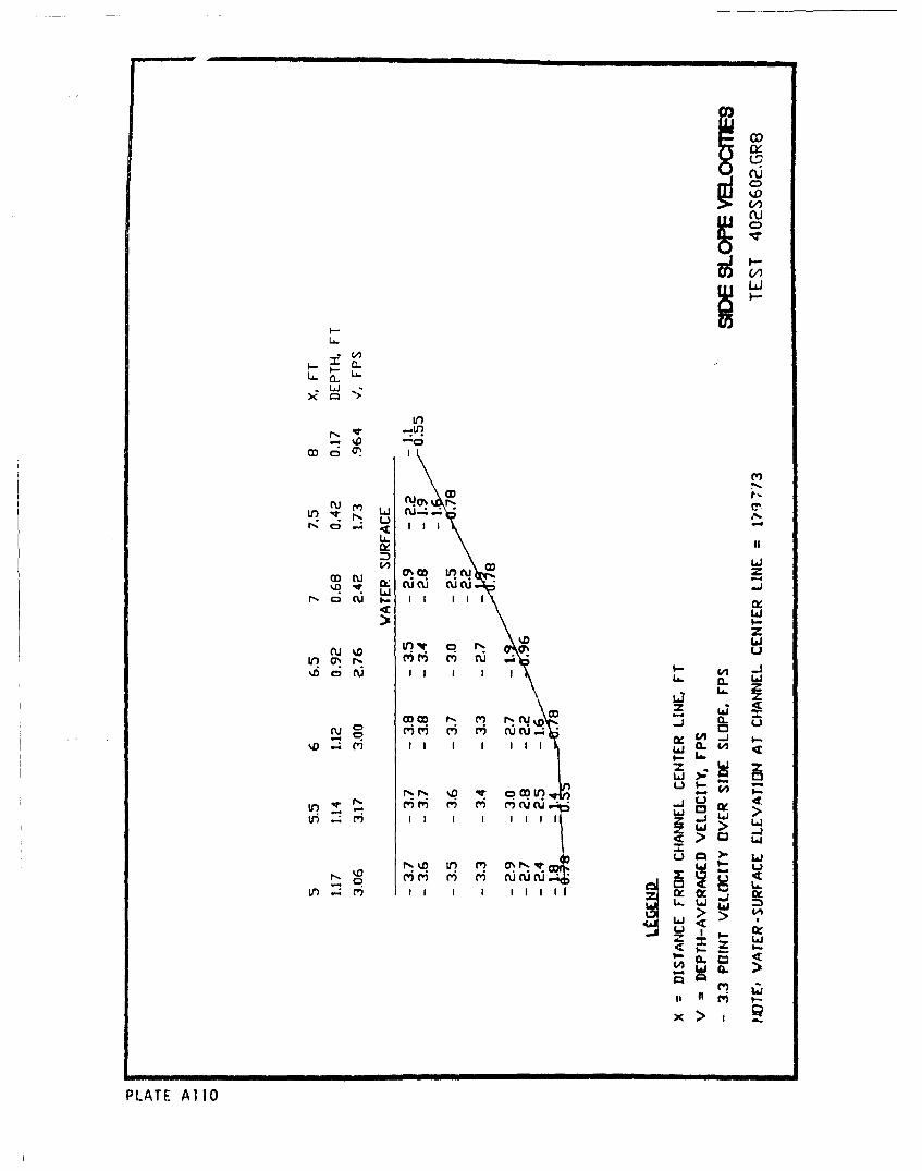
6!
LIIT-ou
0) -)
r-ocu n- IIII
N L)JCýz
LIJ
N CD C I I I I I i. £ IJ
0)- La. a.
6-
Ld z
CA:
PLAT AllOJ L
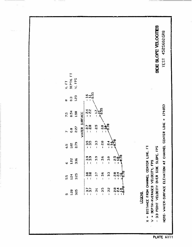
'IjUCD
U.4.0
Inu
~~ LJ
LLi
cuu u Cu.M.oCD .4 I I I
)r I-?
LL.i
N C V) '~i~ cý c * 0co u Ix (: W a i
N .CS ) al1 Ii Ia 0 # of
Li.
In cuc\ ON IQ Ir IY uig>
co CK x~
7.'0 2
II (i >
>LT 0 V1
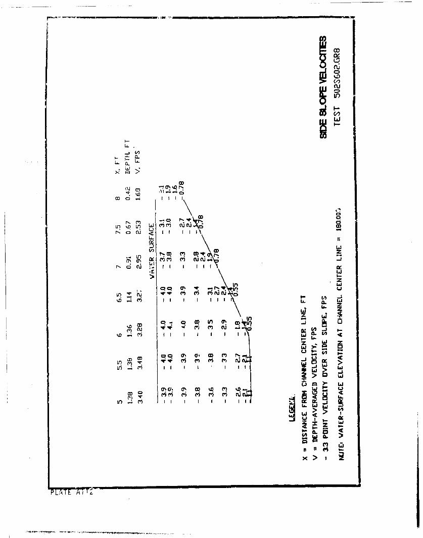
0
o o
N o W CD .. I C ID I W I I
:D LAJ
V.l-C ) CDI 1
Lr) w m ~ CV) -Ai
LrLai
ko LA 0. L ~ O C' .LI
MI n a, M In Ia)Iii. I
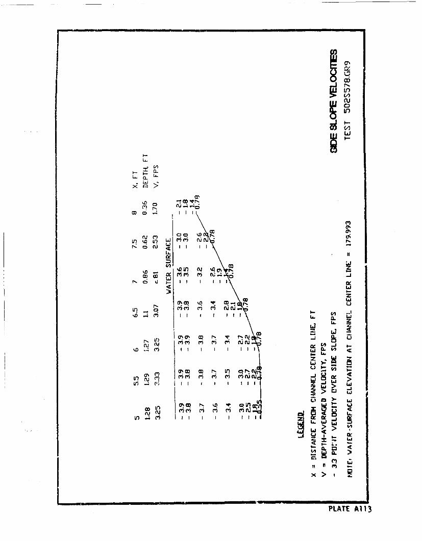
U:
I--
L,,J
C?~OC'
ru M MN 47;
V~~~ ') ýq0 "M NC
NO W C II Ii I
%O %00 U'u %'. c
LL.J
LiSw
mn oo C kP C ? -: CU%
it , ) I I I I II I I I
__. Hl H mi cI N -. II III -
PLATEA1
La z
~I.
z .L~2
r'. in -
>.z- Li
Le () I I I I II x 1
PLATE A113
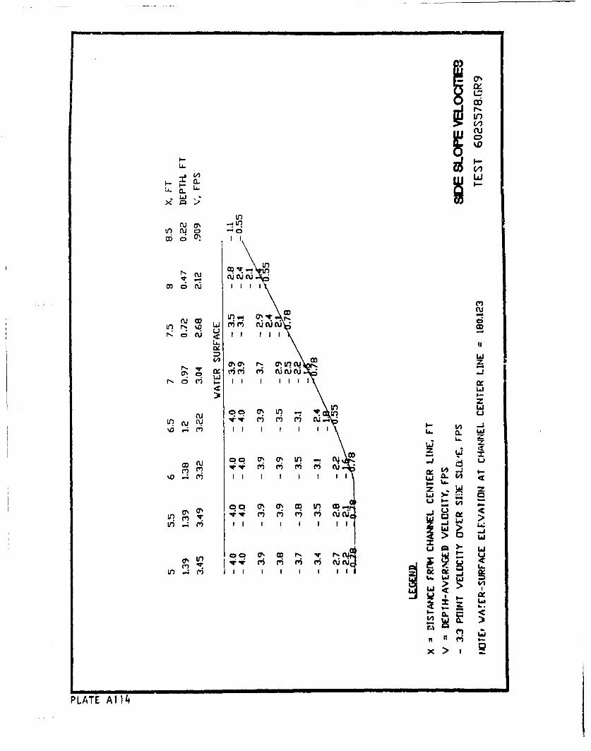
(U(U
C,,
CCU
fJ as -ICý u 0 * 0
CO 'r
Lin
LA-i
0 co zoCU 00 OO' N- u(
IiMI I I I I I IIf
cu v- m C I IIL
N V)CIIIICO rj c CT c~j
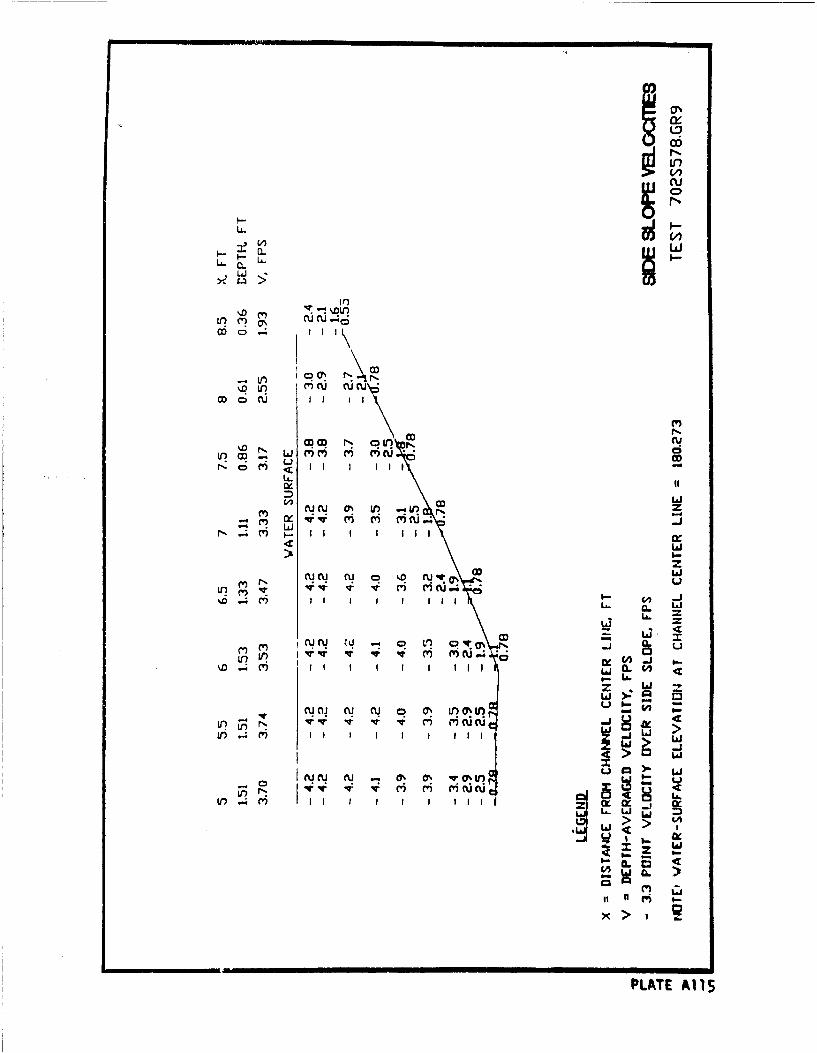
f-fr.
11V)III\
LL.
V)'~ M~ cu o .
a) c) ... hl
V) ru N
CO CD C I I I I
4 1D
U.~
WND N 0 CD7
N IAj I I I I I I 1 4 .# 0:
Vu' C m CV cuatCV -i 'H C
wi .. () i I I I It I CL
ICUCU Cu -% 0% 0%6,
x>>
PLAT Al 1$
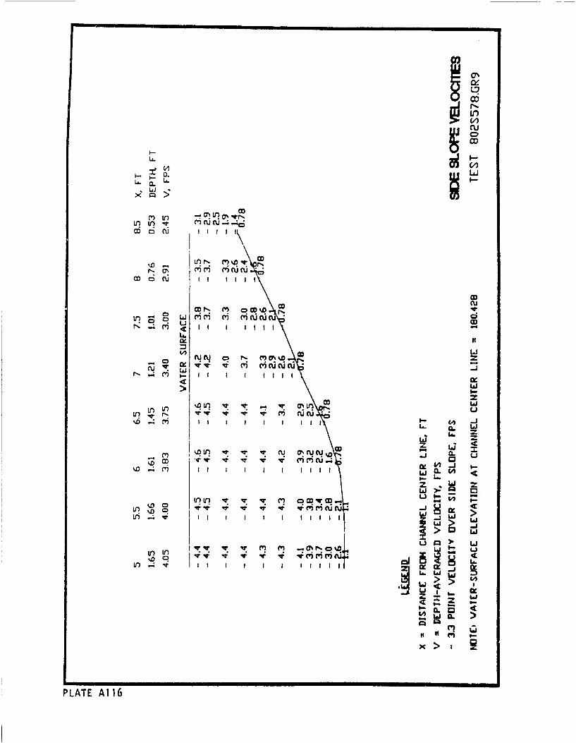
00
m Lo
0 Cu
LA.
CD 0 cu
4,D* -- Ui* * * OD
CU: 0ý CY CV m cJuruu
CD 0a
qq m (T m e') Nucu- -
L6.
co-*u W
V)1V V' (ý c
U.) %q. .* l-t CL u1
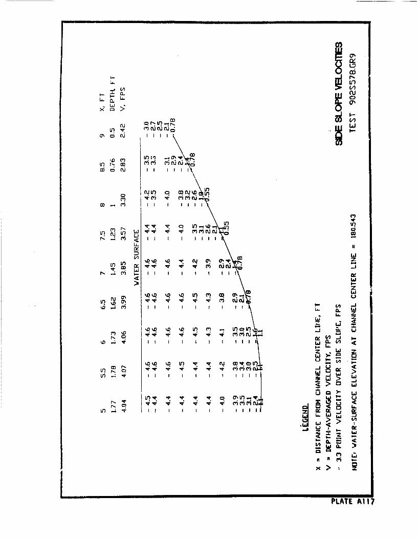
a*.
-L ccuIii
C,)CL a,
asI mZuI
I!o N 0 m i ()uc
a) I I I I I I II
4L
Ina
LL % IfDI) C' ~ U) _'
cq~~ mi z0 ipsCi
M Ii
>~ Li
I~ ~ fLA- LA
I .%D~~~~LT Al-l? u oqw0i
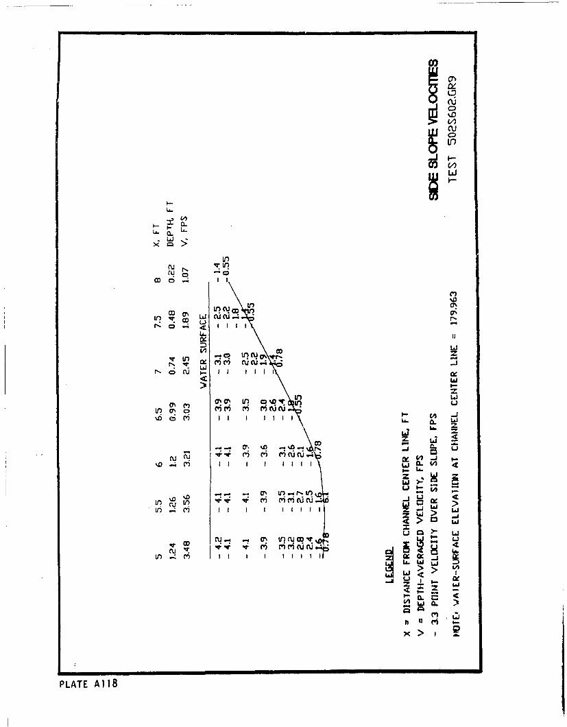
0
LAJa
Co .0
Lr? CD L0
L) U' C D
L&.J
N ~ C CU') *C(. r
Nofl US - Iý i m li ltajr
4 LhJ
it 0-4i NO (4uA ~ 1
CD m' ('i cUC ._U- nI I I 1 il 1.j.1 >
It) IM 1
OD (1 " -! cyý qwmv
QLL WfC W~. Lj
> LJ> LM
xE >
PLATE A118
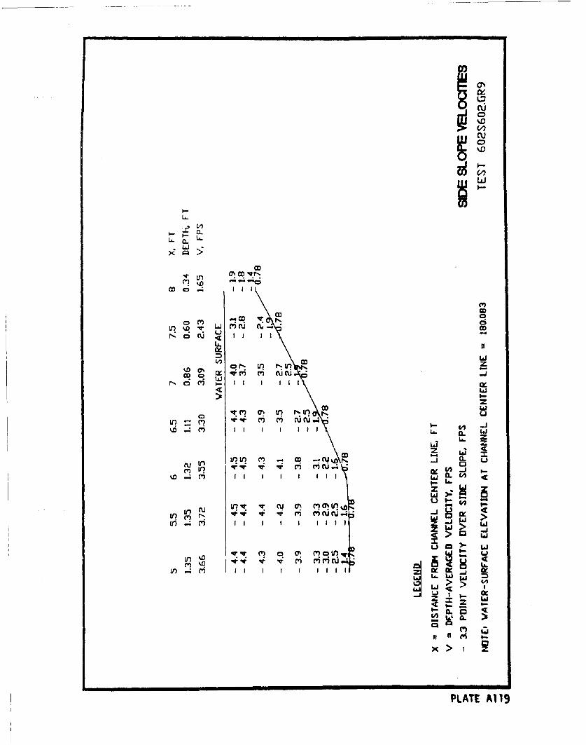
0.-
L~J
14~r
IlIt
ko 0 ~ % r, V 1)C
N~ %D OD
Ll z
cU 0 0C') r' I V I t - c) Cc t -3 --O-4 Vi I I I I I I I I L L
w >:
LO .m fI I I I I II Ia > LiJ
LLa
) 4m I I I I I I II itJ0
(x o1 i w'
L>~ >iiWf~~C7C~i
(~L a 0% CU
PLATE A119
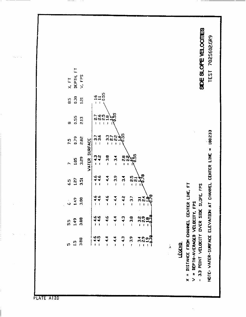
Lo
I'll
r ,- i 3 i i I I I , -
U.
%D
o •C) - I I I I II
O 4 : Q m NC. . . C4 c~
I• , •I I I I I I ,I. . 1
r-Li 6. cs 1 1 1J
LO as % 0 MN M -tN*** O* L
.4 cn
>
D _
LnW
IILA AIN U
%6 ~
QX > cnI
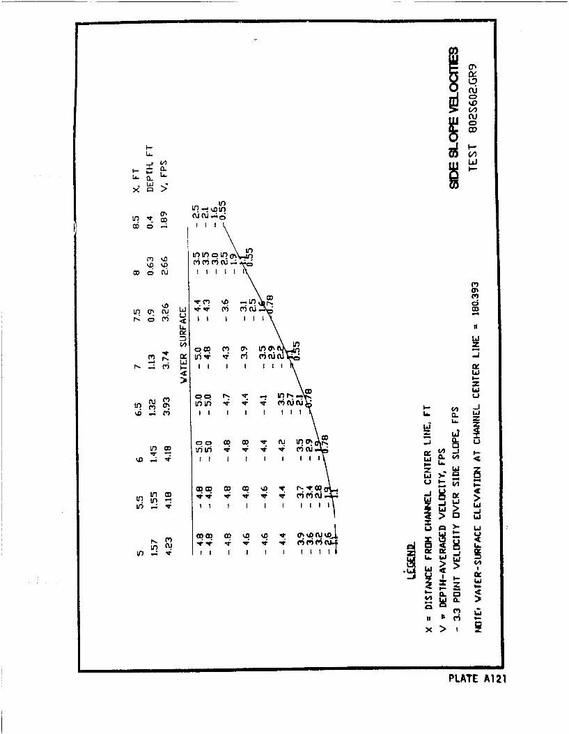
hNI-m
L~0
LfCo~%
CUC~JCDIICI
a. flUQU CL LA
CO,
U. N
C? I PI W? II
V) U) 4 MCUCUt%D m 0. W I i .
L&.
U~CD uii
'T~ -~ A ui ncuI W _Lj
w
inI m m
Lo ~ II I I I I lI II
>t~j>. L.
M V0% D U %j I-Lo a!~
PLAE 12
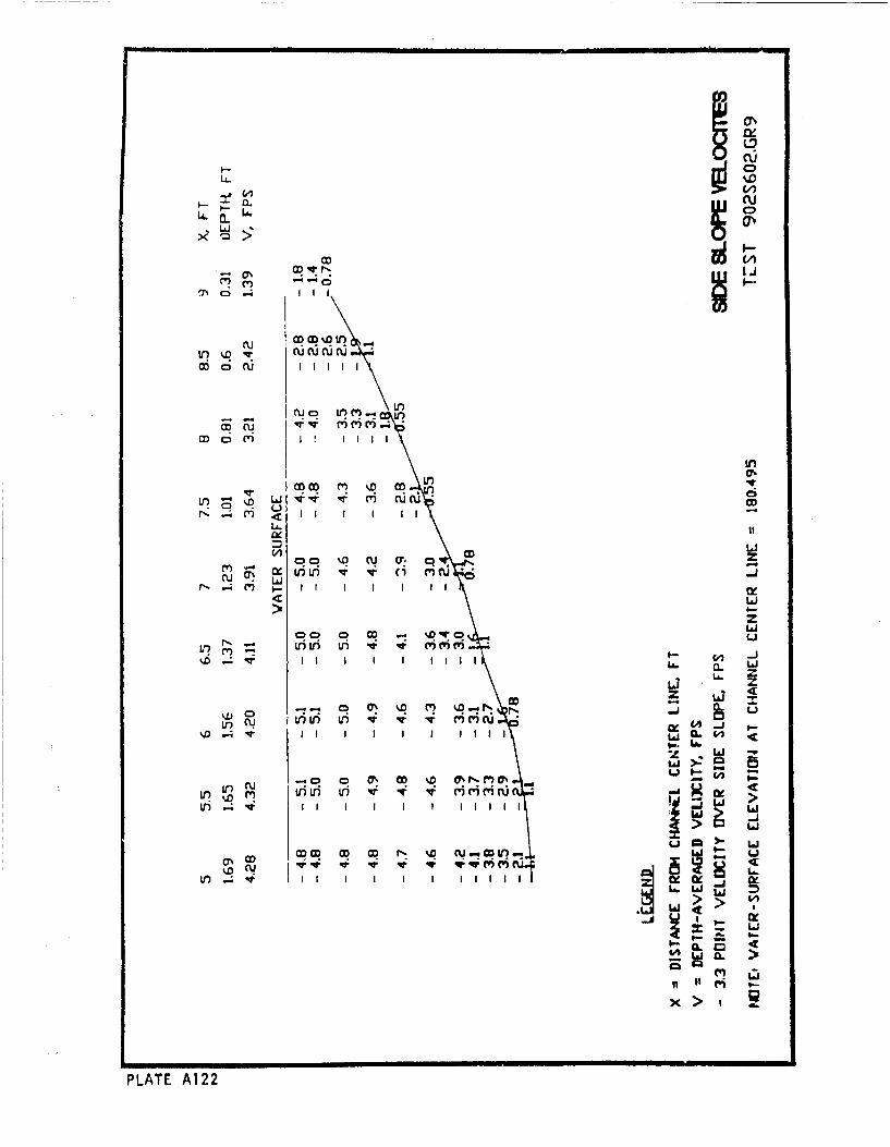
LAJ V
cu~0Cu cu cu
O a) I I I IUI
In
Ul,
c). C)I C . )
0 i i ri e -fu Li
zCDi
LoA
V-) Ic P: ( 1 1 2 . C.
L 4 vI I I I I I I 1 1 I LIII
Lai
ýD N
ii of Ei .
PLATE A1
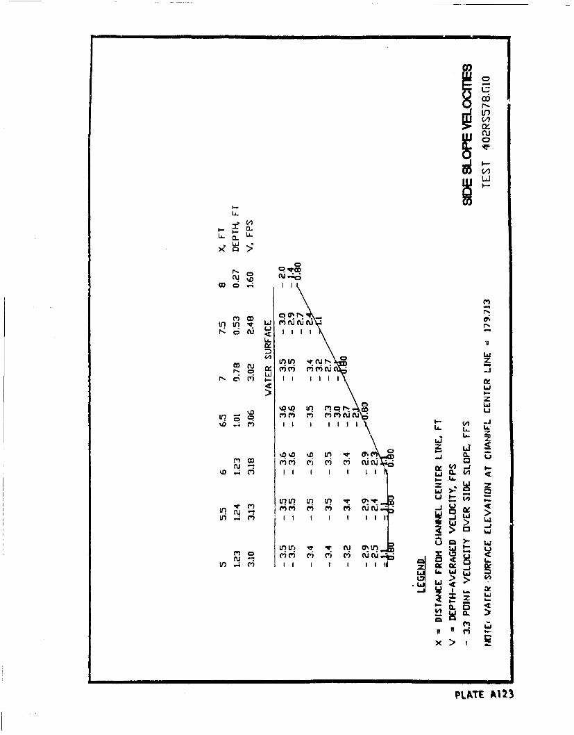
U.~~iri
00N 0 N
LA..
LLi
C5 MCD 'f
M CD 0%
U--
0 tiJcu0 '.D% U) qtN Am r- C
LAJ
z
1Lz a,
Lai > ~ La
vi~~C' -V Ij
X>
uLT A12
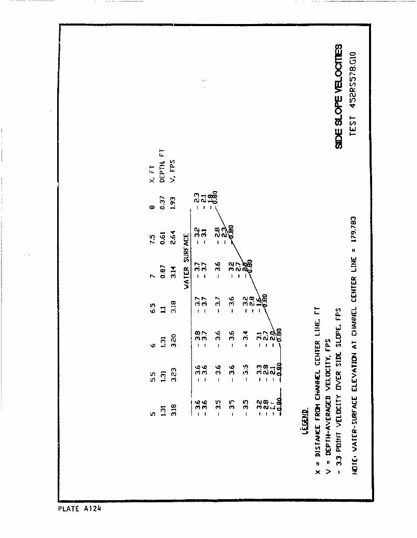
CD
LAr)
00
n~cu,.uIIO
CL,
U- CL
ODr %D .4
) I-2D
MI I I II I~. ~ L
Go3 Li.
-~0 CD-
II w I ICLJO1 C4I I6.
M~ CV~C) M, c') t1' W c uiL)I I I I I . j 1
U-i
> Li
PLATE AIa
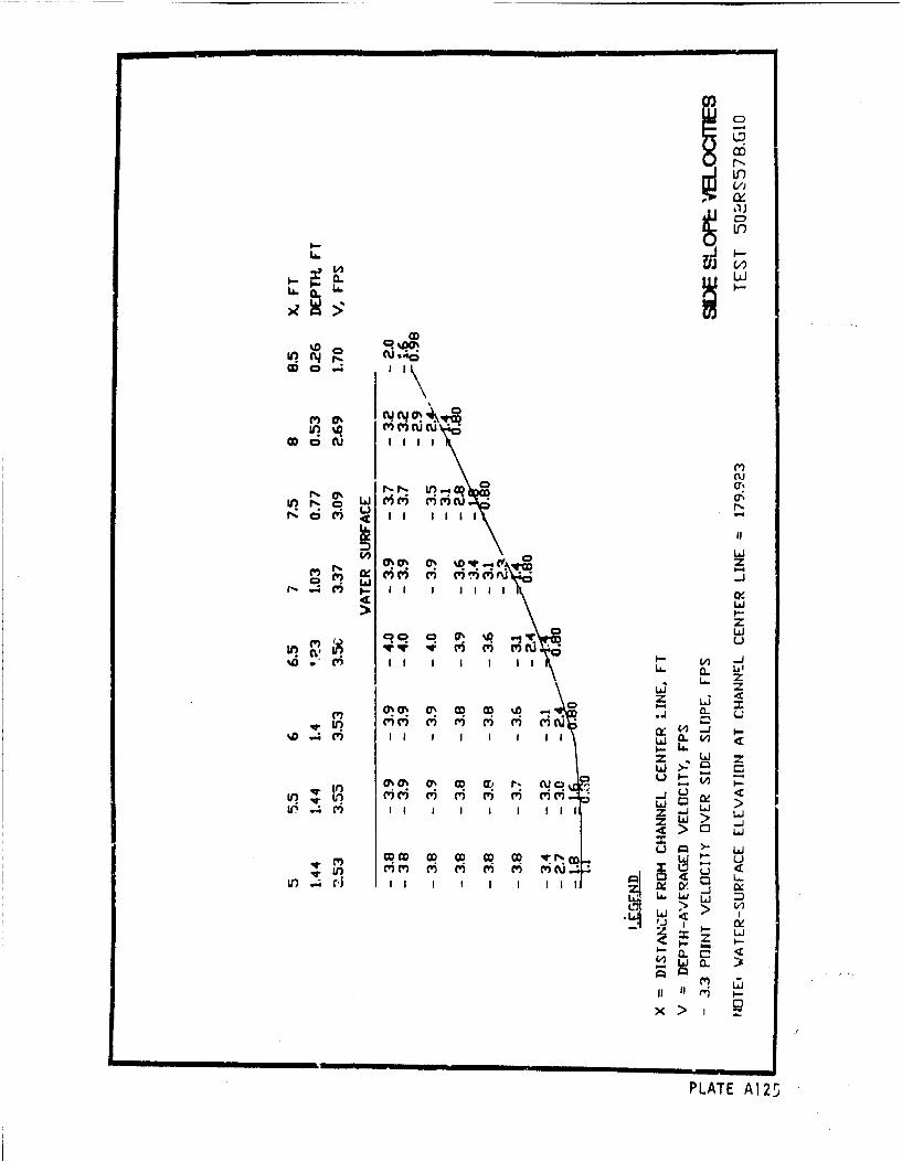
CI
CU.C)
C') Q)
uW~ C 'U)CC
Wa(U lli
CD,
C9
m i CD)' 0 u'c~
I--I
L;i
z L zqo oa'%..gW L
.4 ~ CY c'i C') i' 4m
V0 0~ asO D - C
Z L LiC'IC')~ C') t' C) C' C
~D.4C' gz I I I I
ULO r' I I I I I I I I IZ
I Li
m CJ
PLATE A125
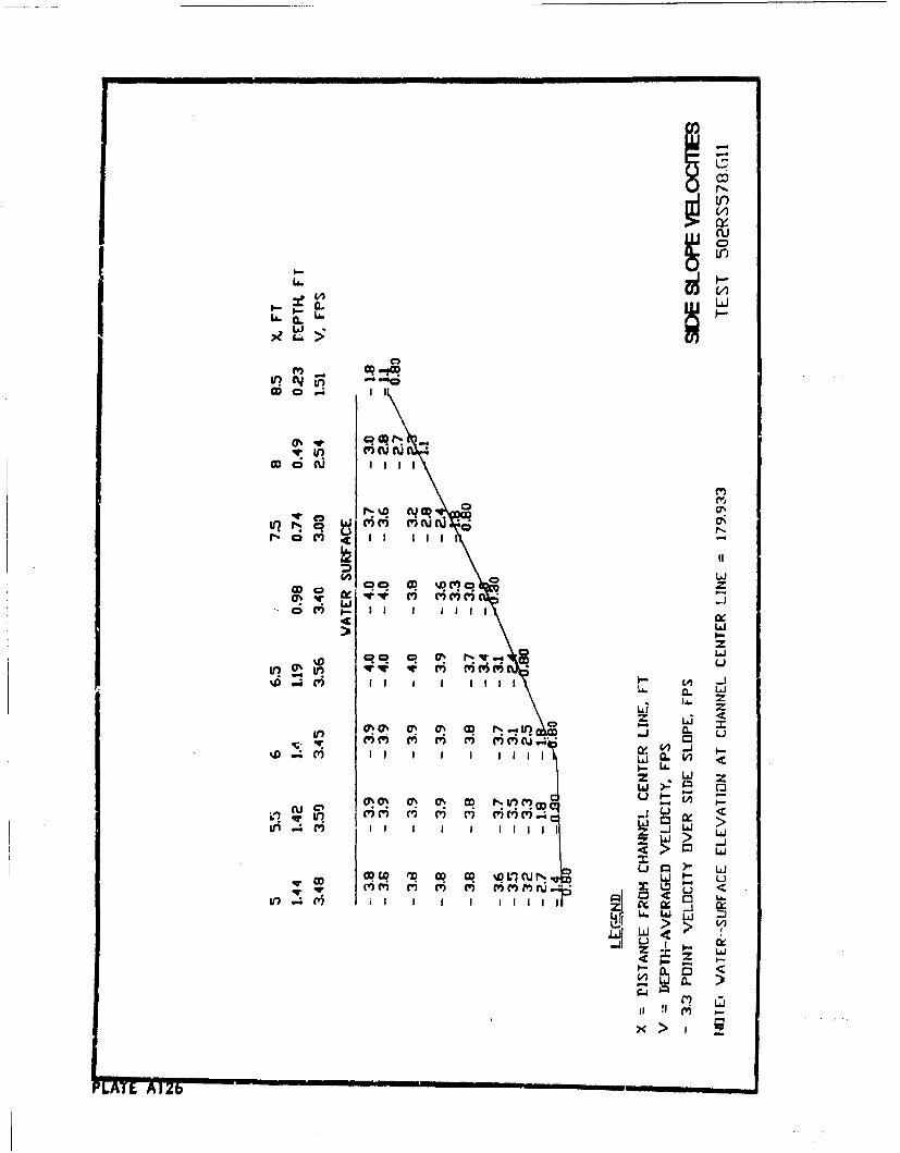
C6
La -.
V)
C,,
IL W
ODa
(q aqv vi r r) r rJ -
C2
M0
Z LJ
~ 0. u~~Lh.
Llaz LLI
1r) -j uj
U,~~~~C'i MiI I I l i
0" >LM ~ ~ ~ ~ ~ ~ ~ i .4 cv IIII_
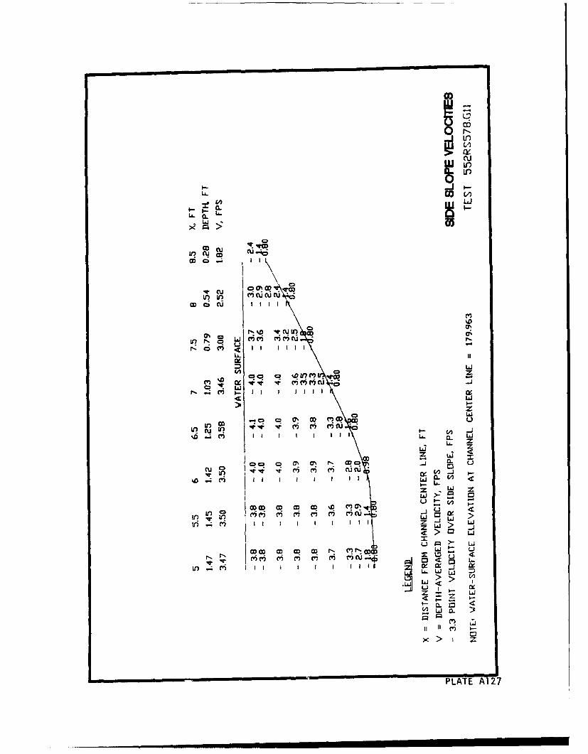
co
I-ý
LL (u
0.0
r-Q WM,0w La CU ~ '
rIt liii -.
LL It
e z
LO
a. a
C~zU CDC4n0 0 0 0 1' 0. 0
w >-
in ~c' II I I I 4 a LZa w 5
U> 0 L
L. UJ -
u I -
z LAz
PLATE A127
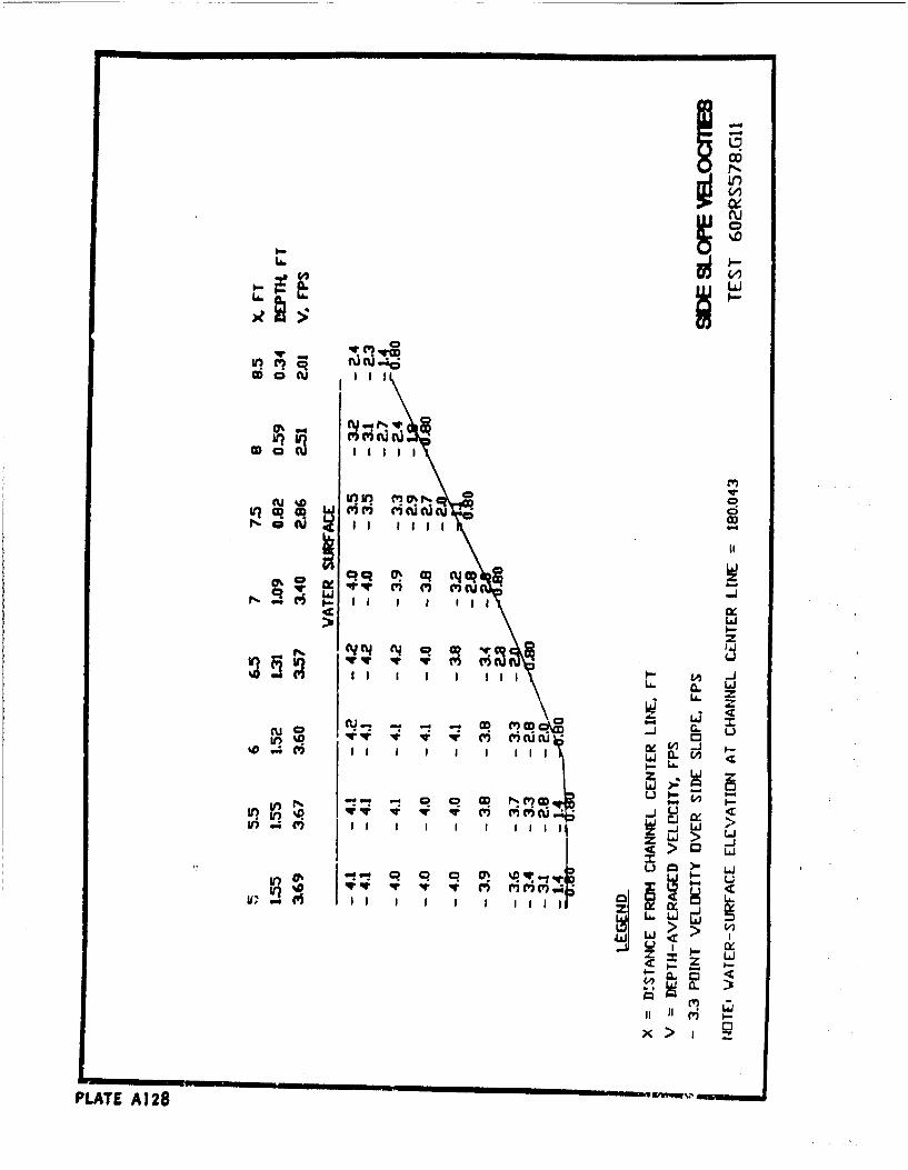
LIJ
CDu
cau %D U
InA U. PI N_:
4c:>~Lai
LA. 0. lALA. z
LAI~
cu( j -. -
~~~o V) -') C)CJMi CL W
1% ~ RorC6.
PLAT >:2
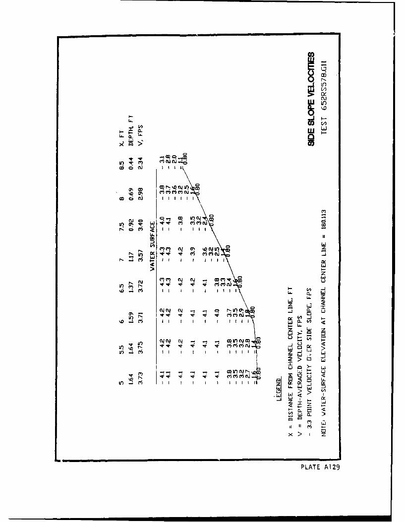
Li)
0- 0
Go C U . . .
u0% .o 0DN% uif. C
00 CU i II-
u OD
V)M cu %0 cu 1r) CD
N q (CC)
CV) (W cu C.,'jt w-)
D M I I I I I i I w . L
LAJ zz LLS
in r-.*o IX W -
%D M I I I II I I c I IeL L
7- Lu Z
"- - : ~ - _vju~ U -T
tI) Ir I I I II Iu .
Z -j LAI
> Li~L)O )
Mi NI eri %DM
PLAT A12<
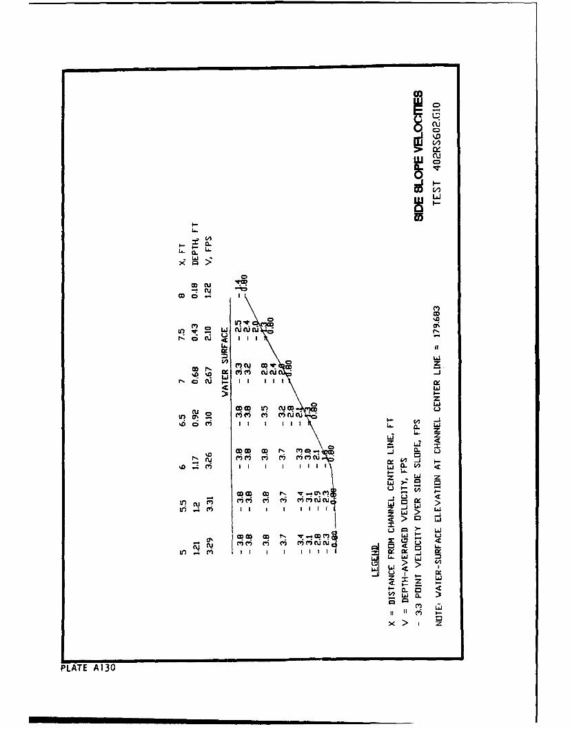
)CCD
~~cu.- ~(u(D
CC,
f-ocu III -
! cZ
r-oclCU -C I I II
0 LLa
zx 60 La
C' C'U ~
.j
U
z LI
LLI
I I I. Ir ~ ' W-. iCUC ~ I I I I I cL6 a La.
zz
PLATE A13
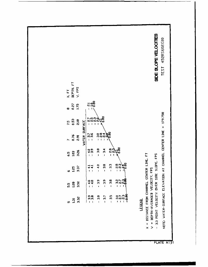
CD
C.16
CUL
LJi
N u W
Lii
N%) tQ --
Lii
z0Ow M C Lii
(L W
Lii z
z L 5
CV) Lj IL 0 I
z Wi Z
iII a) W? I 1 CU L L ii
Z &> U,
0 Lj I--
cu ~ ,CP C ' x'r(- Lo(I? r i cu U'C < 0i
w ý L Ln&J
< z
PLATE A13 I
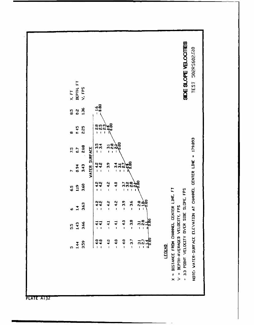
C>
0i
CD--U3ri
a. 0L
LO If)C; a
CD It' a
4cw
M0
aZc~ v lz Iii 6-i
U. IxLIJ
0 z
%q" .-. ' -4
(nc I I I L6 C LL
L&J
ar Lj 0 w~J
ui c) I I I I I I I I Z - b
Z LJ 52A
> 0 > j
u La.i
IT IV m ru o <iV) CVmlIx : CK cL. wI
>I
PLATE <1

00w
0
U.-
cu cu.-
CD
LAn ID -WM UC
rzI
0ý cu ni Au
-LJ
inI In m a (5
0 Ld
z
CU CU Cu 00 VWN M
I1r) (I i (1 6~ 'icn -o
ILL I l:
LO W4 cv)Z -J W
-~ -- 'j > C3 i
WL&
II > zPLATE A133
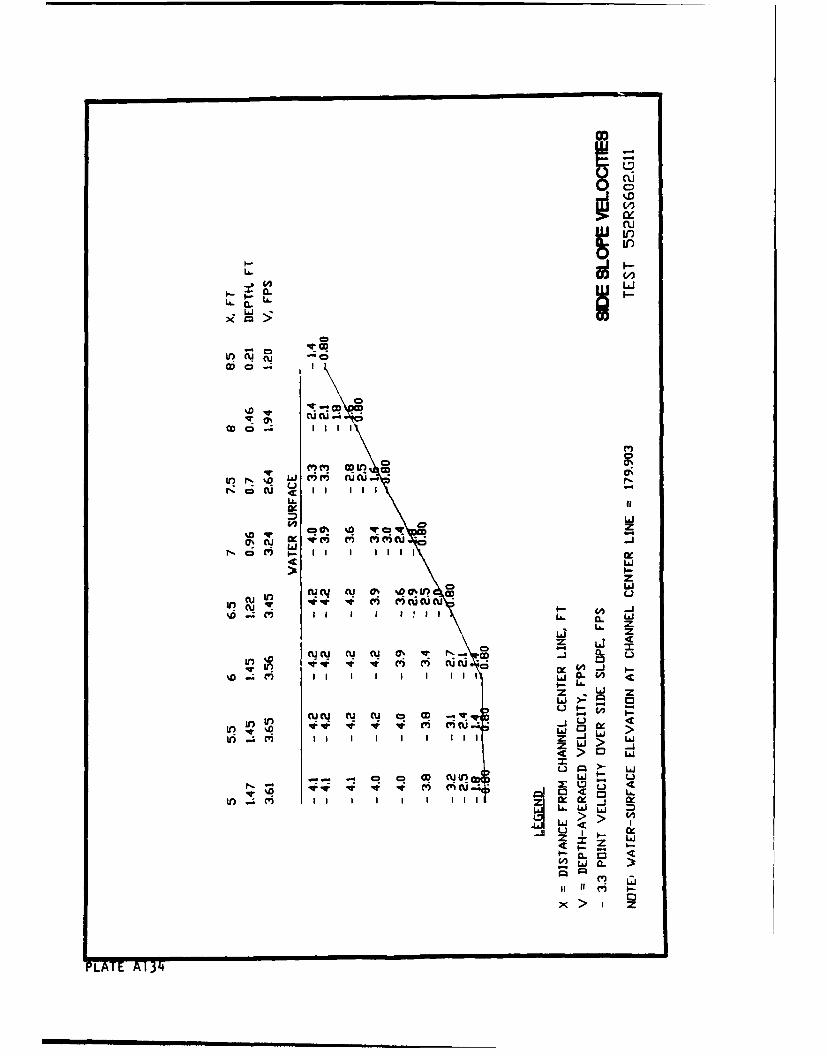
InLi.O
0u
-o
CD'CD c0
LC'A' u CD
~0 C')CD
CD C 4 L&J1
IT -i V? C?-i)ur N %Q W 4 M C C') UCU
LA. It
n a i Z
aC CU I)j ri 0V) -. c, =r, ~ci i ) I I I I II I II LJK~
zc L J
CY C C'Y Qý -pov CD. 4c ~- q V CV) cucucu-
II~~L z I i
(%i(%i W Ci CS l N- CD - X..
CF) La
II IL I I
ILI >: C 3) I
U U 4c
NLT CU CUCUo3D
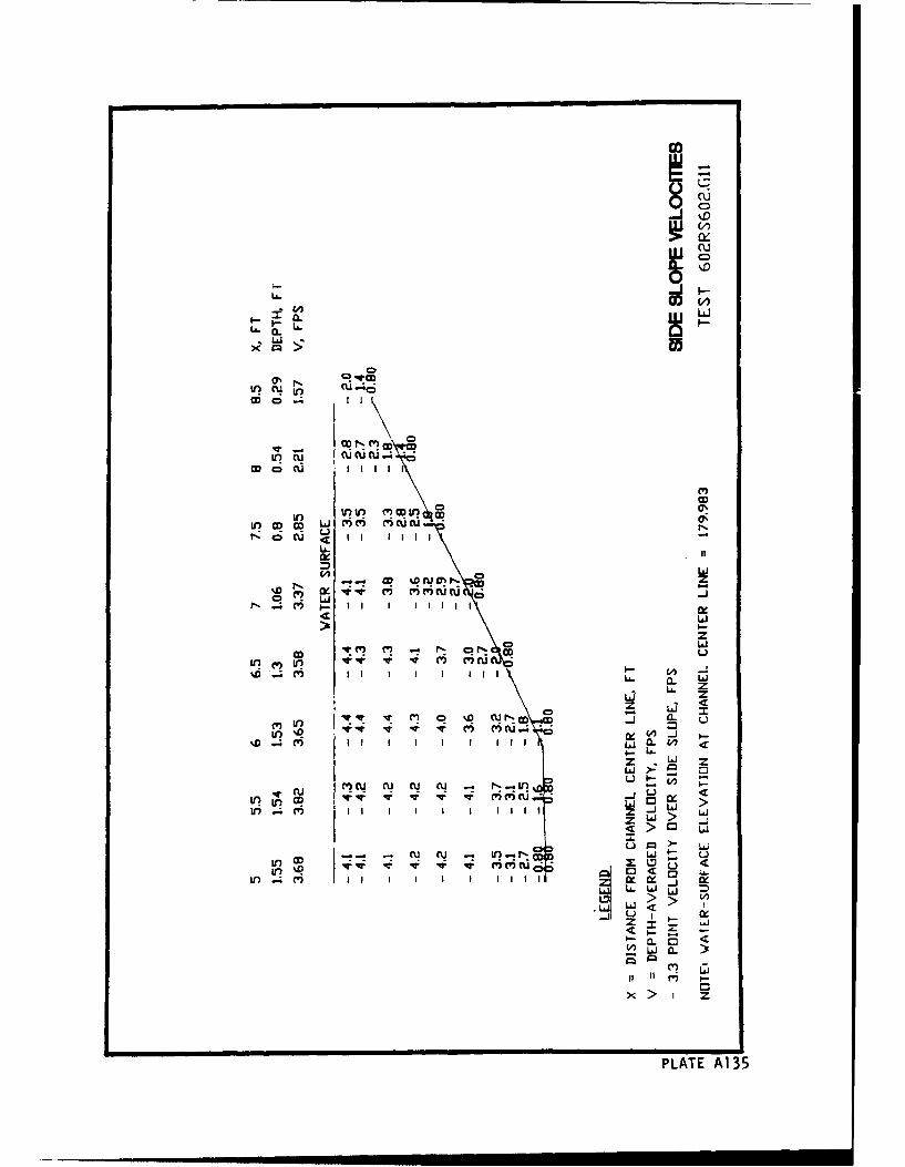
Eua.'.
V? N U ýC
~OD U I I I
10 IQV0' Rn O
N cu.q C') I I I I I
W L1aCK i .i 111161% -
4 Ld
zw
piL
La Z
L6 z
z Lj <
CV) C3C V '...~Itn C) w 0- -J)U ~ -
%D ) I I I LA 'Li 0.~
Ld
CU La
-r CU nQ 0- mir >.~ LU,'. 'q- ~ ~q C'C')C~I - ZL~(J
mc5 i ZI -
jr)~~C' CDw0L
LI CV) 0 -
PLAT MAj e
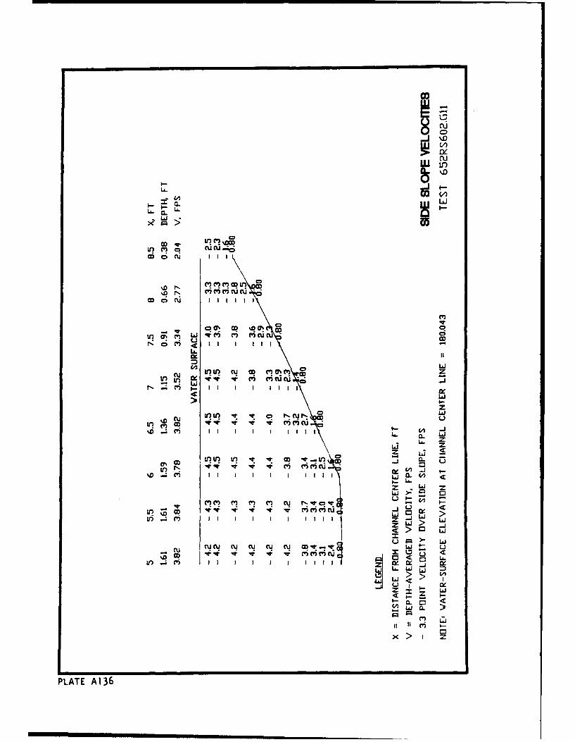
LA.O
LLAJ
OD'~ CUC.-
Cr)~ M () C
in CT C'ý LAJ W~ M (%IUC 0ucu CD
N0l) <~I I I I-LA.
LAJ
0 zcu Li )~cwnc
L6 zLd z
0 La SOD U V? 0QLr 'T (U r n ' Lu
LAJ Cuz
v' v' C') M C' ) CU _jO U,
InV c' II -J IL >
Z L' > LAI
-~L) J Ui
w e q qr qw M (W) t) C 4
PLAT LA.6
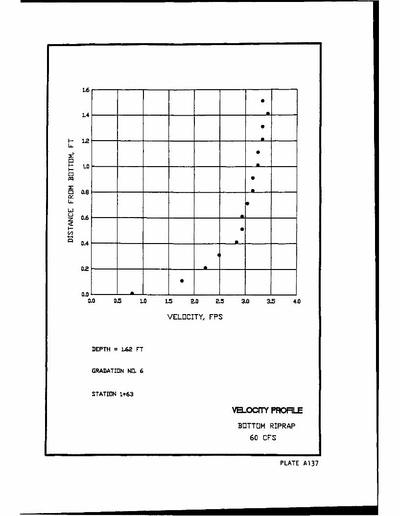
1.6
1.4 --
S1.2 -
DS
I-- 1.0 - •IL-
30.8 -
LA-LLJ
z 0.6
b4
0.4
0.00. 0.5 1.0 1.5 2.0 2.5 3.0 3.5 4.0
VELOCITY, FPS
DEPTH = 1.62 FT
GRADATION NO. 6
STATION 1+63
BOTTOM RIPRAP
60 CFS
PLATE A137
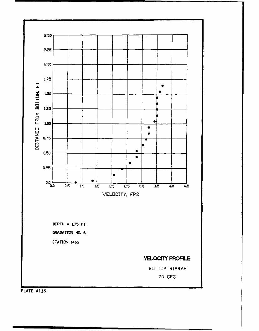
2.50
2.00
1.75l--
:•L50C3
1.25
L. 1.00LiiuJ 0
< 0.75 -I.-
0.50 -
0.25
0.0 - a0___ _
0.0 0.5 1.0 1.5 2.0 E.5 3.0 3.5 4.0 4.5
VELOCITY, FPS
DEPTH = 1.75 FT
GRADATION NO. 6
STATION 1+63
VELO. Y PRCFLE
BOTTOM RIPRAP
70 CFS
PLATE A138
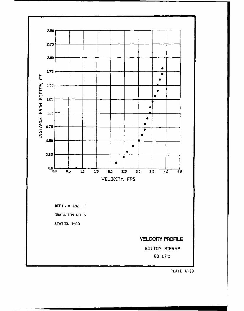
225-225
2.00,
1.75
I.-
-i 1.50 -
I.- - 0C3
r 1.25
C3
L. 1.00 -
S0.75
0.50
0.25
0.0
0.0 0.5 1.0 1.5 2.0 2.5 3.0 3.5 4.0 4.5
VELOCITY, FPS
DEPTH = 1.92 FT
GRADATION NO. 6
STATION 1+63
VELOC"l PRO*IE
BOTTOM RIPRAP
80 CFS
PLATE A139
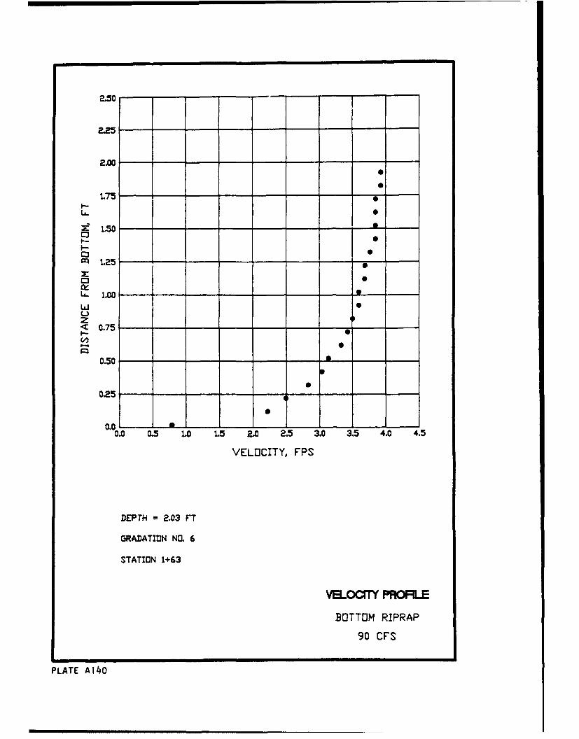
.,0
L 72--2.00"
I-
S1.50
ZSI-• S1.25
1. 0
zS0.75
0.50 -
0.02
0.0 0.5 1.0 1.5 2.0 2.5 3.0 3.5 4.0 4.5
VELOCITY, FPS
DEPTH = 2.03 FT
GRADATION NO. 6
STATION 1+63
VMoCX= PROFLE
BOTTOM RIPRAP
90 CFS
PLATE A140
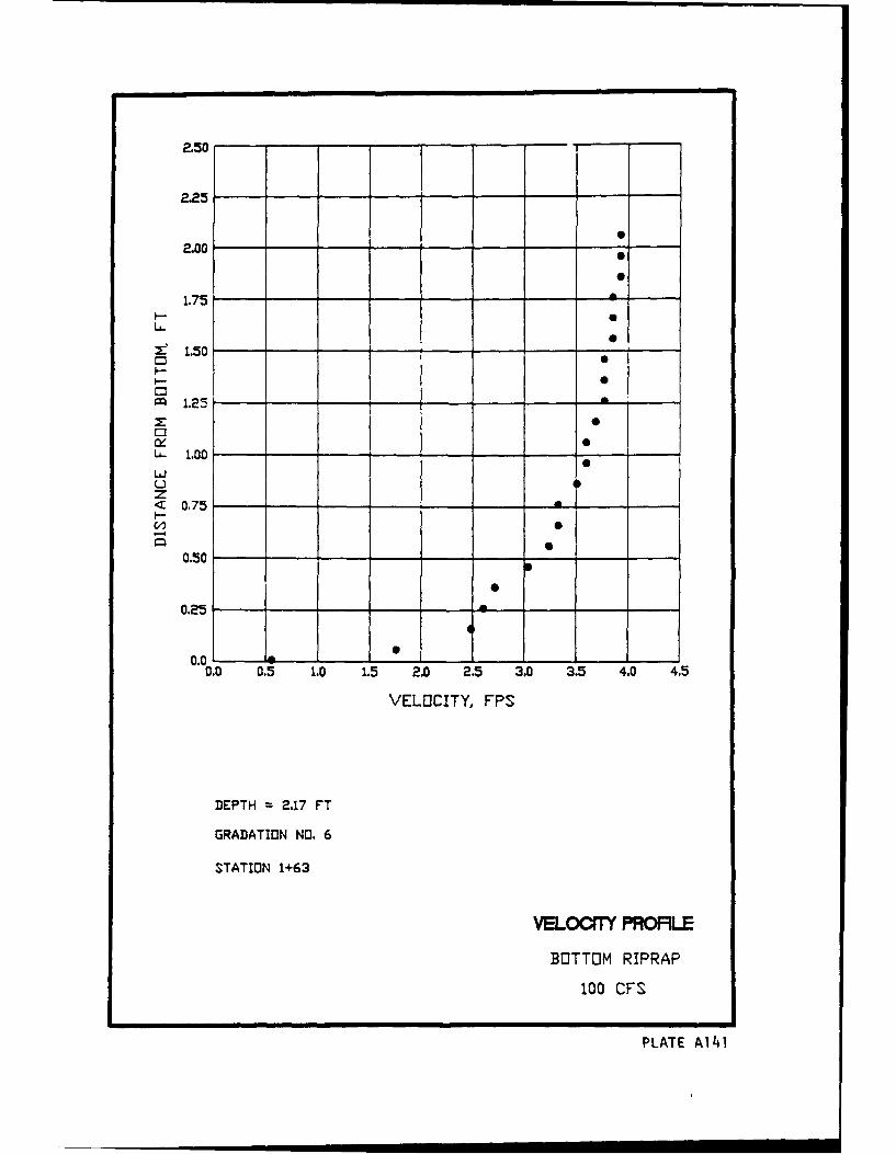
225-
2.00o
1.75 7 5---
S1.50
m 1.25--
E---
L- 1.00 -
LiJ US
z< 0.75 5-I--
0.50
0.25
0.00.0 0.5 1.0 1.5 2.0 2.5 3.0 3.5 4.0 4.5
VELOCITY, FPS
DEPTH = 2.17 FT
GRADATION NO. 6
STATION 1+63
VaLOC"l FRORLE
BOTTOM RIPRAP
100 CFS
PLATE A141
l ! nI
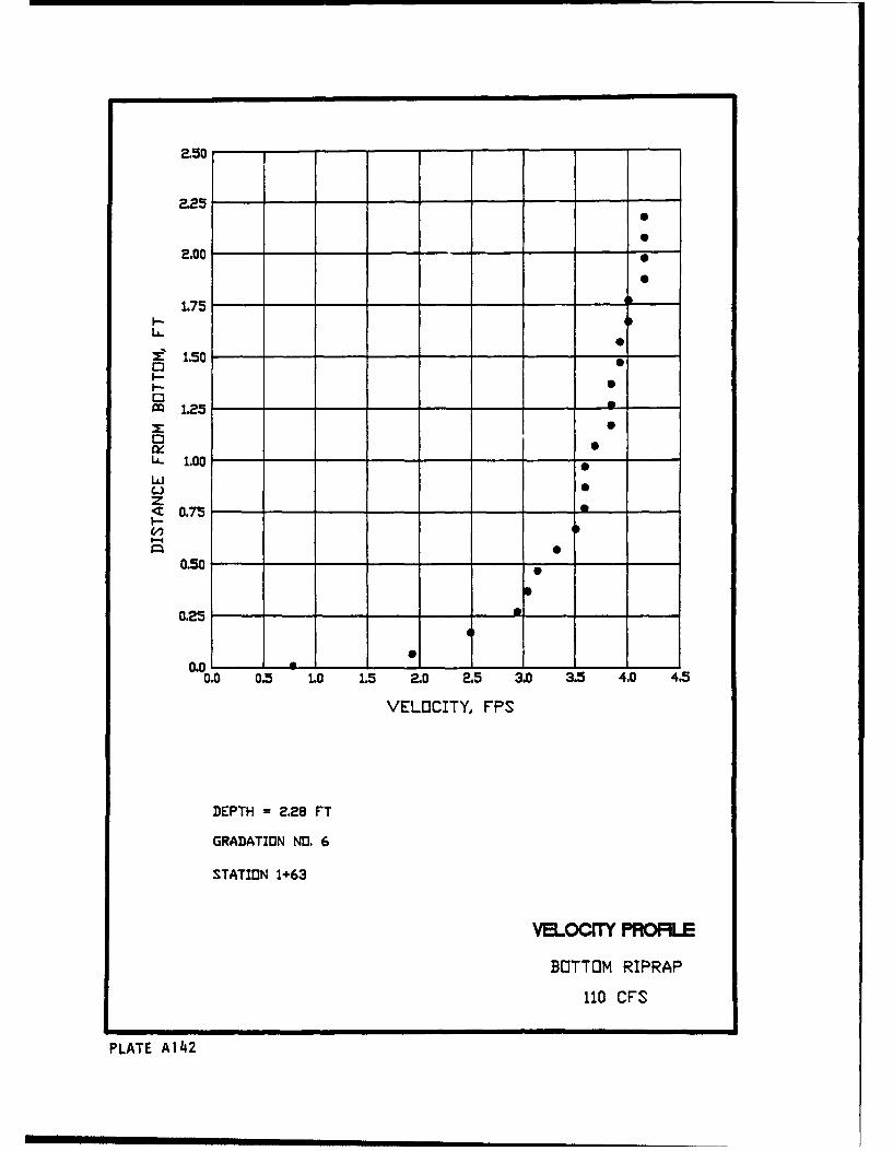
20
1.75 7 -
S1.50I--Mm 1.25 -
QS
L' 1.00 0 -LaJz
I--0.75
0.50 0 -
0.25 -
0.00.0 0.5 1.0 1.5 2.0 2.5 3.0 3.5 4.0 4.5
VELOCITY, FPS
DEPTH = 2.28 FT
GRADATION NO. 6
STATION 1+63
VELOCC PFK)MLE
BOTTOM RIPRAP
110 CFS
PLATE A142
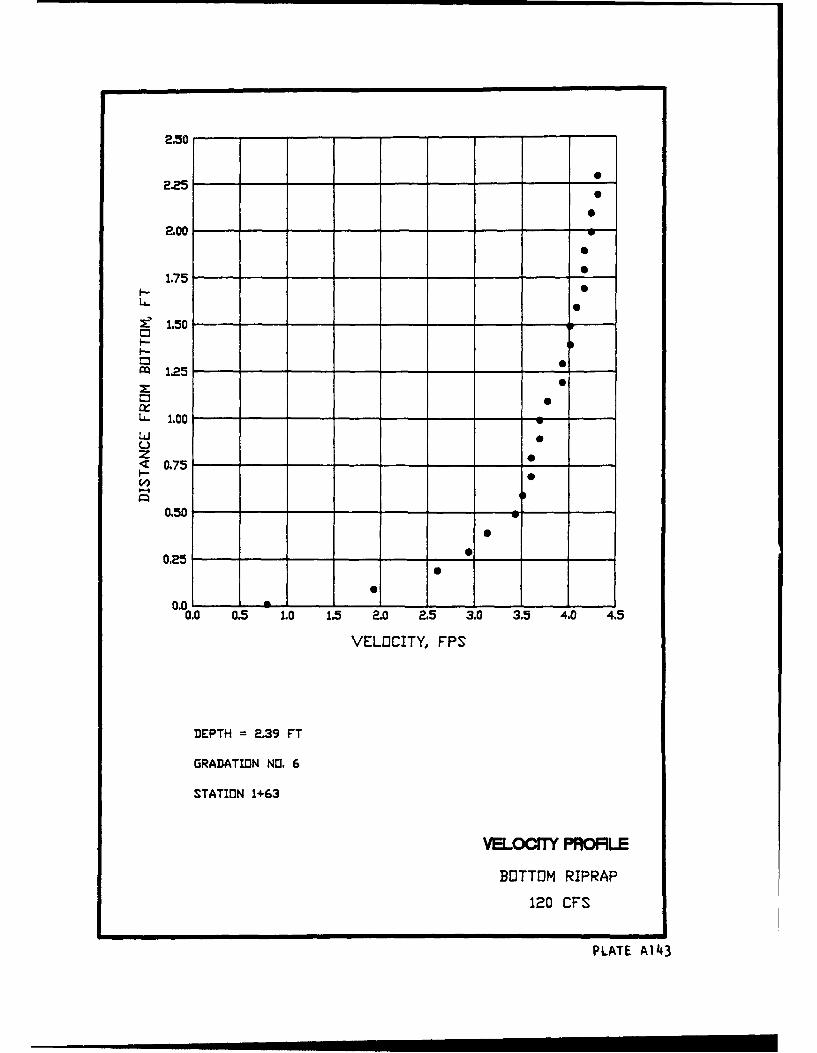
F 2.5C 1 -- -1
22500
2.00 -
1.75- -
M" 1.5 5I-C3
m 1.25z] 0C3 x0L- 1.00 -
Liuz 0
0.:75i--4
0.50 -- -
0.25 •
0
0
0.0 0.5 1.0 1.5 2.0 2.5 3.0 3.5 4.0 4.5
VELOCITY, FPS
DEPTH = 2.39 FT
GRADATIDN NO. 6
STATION 1+63
VELOOITY PROFLE
BOTTOM RIPRAP
120 CFS
PLATE Ai143
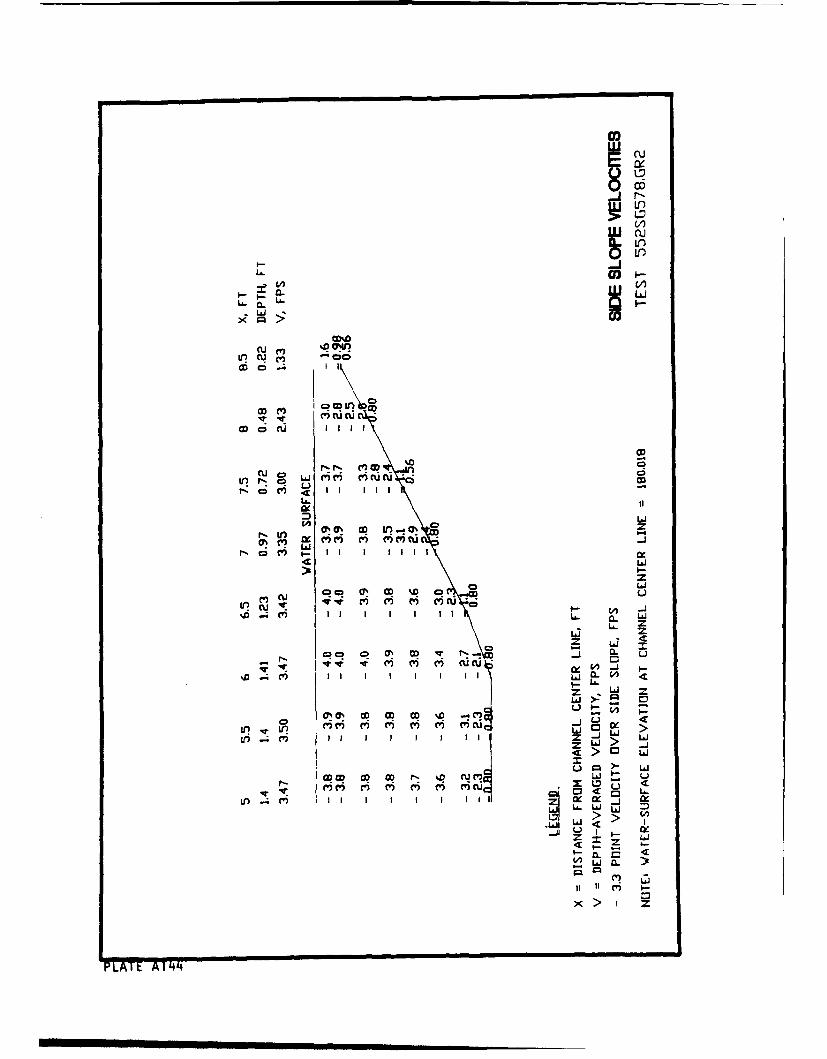
0,
w6
LcEj0I
-(40
CDC,
co ()ODI -ITe "Iti
cit' I6U Q O0
LL.J0 z
M *CA Y~~
M t L 0 M Cr-or c; 6I I ixi
C3-
ý D 0D L
Z L&
00u CL O0 -C -. 4 .
Iz L.j =.
LaJ
CRWq GW cqr-% Q ~ LUAJ U
-T~~ 0 -C 3 L
Lr)~ ~ ~ ~ .4()1 f rM C
>,
AI I'5 9'
L=
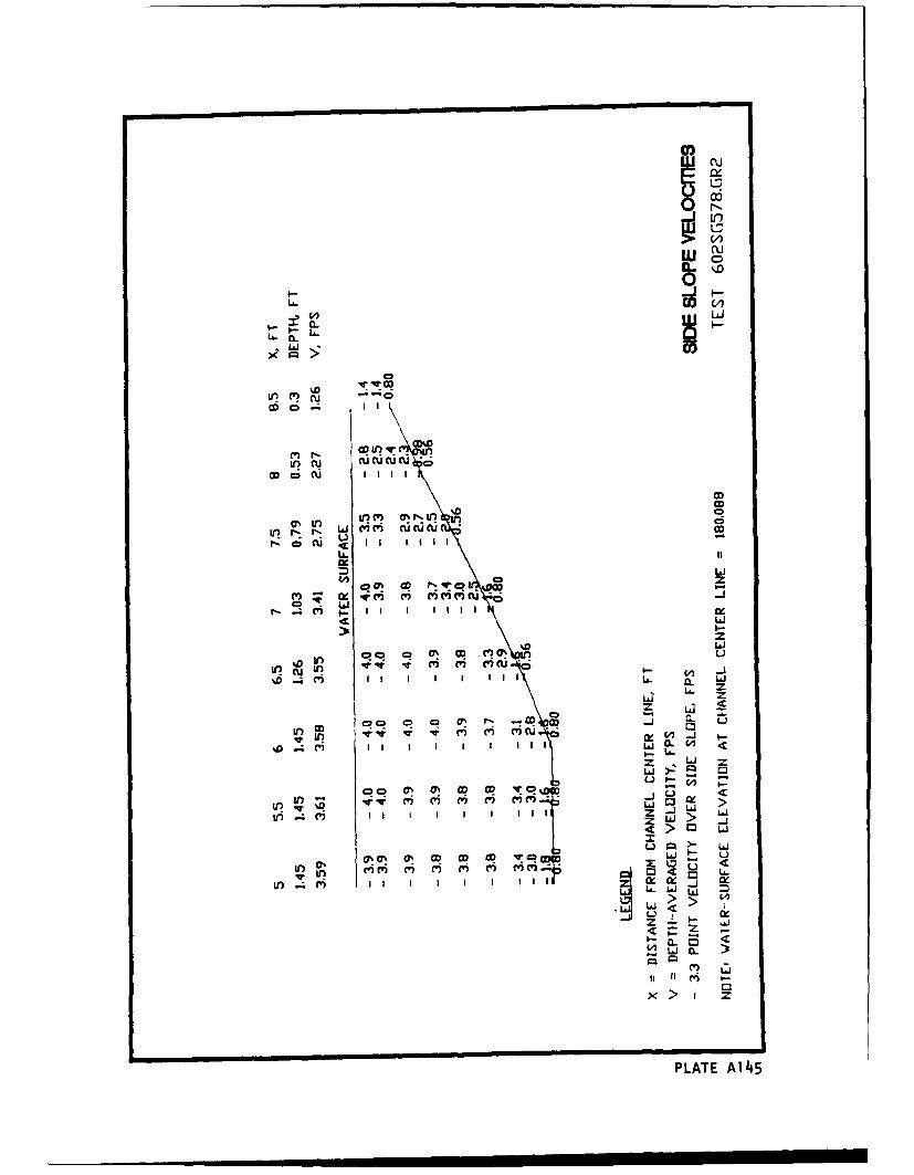
Cu
Li'n
~%D
lI\J
Mn' aru
tr r'j L i ci 0i7 U(cuD M CU I -
~OO-oc
r-Z CD C -C I I I I l Ii
Lai
cz~jf c ) CV) M M CU )C
I. ILiA
U. = L _L
I L6-- ,
I Z L z6~ LiLj
inl V ' C' C -) m C') -mf..' II I I Ij CL W <
z> Li
L'i > Li
ui L'i
C'C' C') m' M' C') <'~ ~ Lýi) .4. (V) _II 1 1
Uj L
CL )L61 C'i
PLATE A145
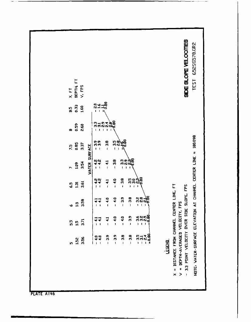
cu
~'~0
~ Li
OO CD Cl tC(
Ir i iiD Cu II
C CD
0U.
Li
CD L i.
wL .4 () I L L
Z Lj
.L. 0 In v -WJ vj V. LI V cijCUW W
%0 I;t. I I i i 0. 0
I.)LI..
Z -JCI 0a >Q4 L-JLILCU"C 4LI 0
PLAT we m m w)m(1 60-
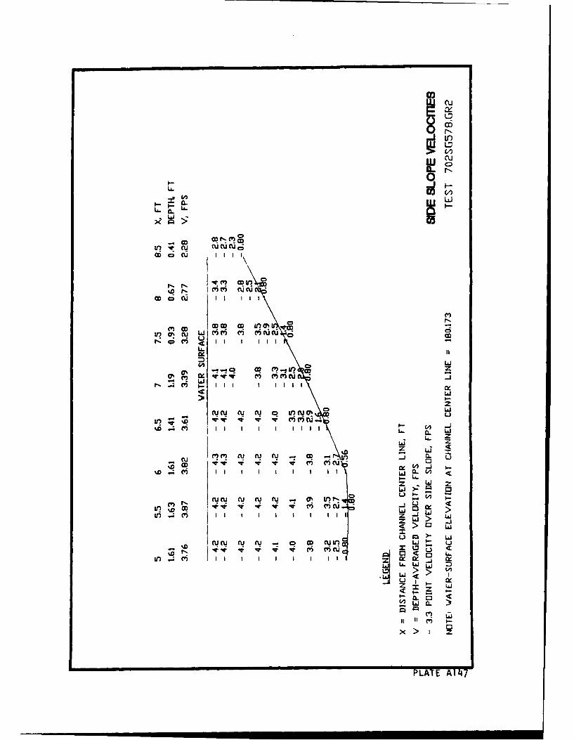
Cu
L&.n
~ 0
LA6
OD CU II I I I ii
Mu OD nR q uCeu bp2!i
II 6 L) I C) 1 OD L
LA.
2 l
CU CU C I CU If cu 0% CD~- C
4 L)
M I II ZL6 C>Li
z I
-u P i c cucu,.owcOD i~ IL
II IX I I I
z L--L-i >:
Ln ~ ~ ~ ~ ~ ~ ~ I II m IIIZ -
P LAT > 14
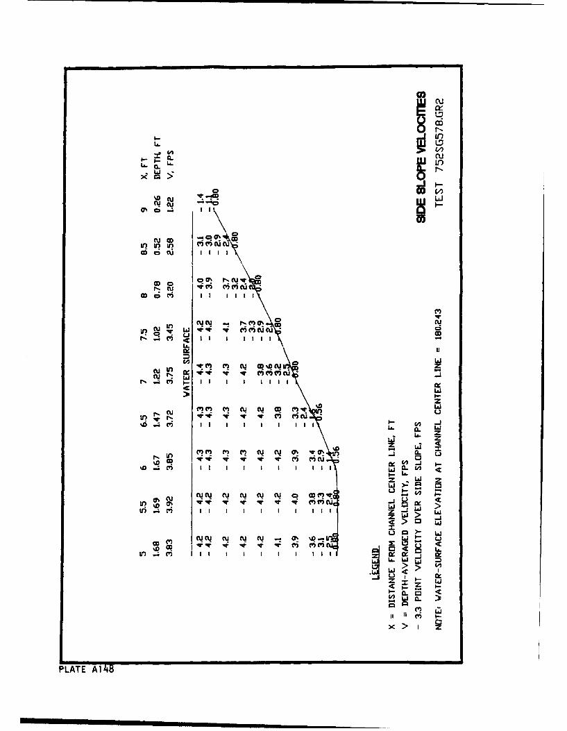
rucu
CC
%D CU -A
..O Cu) I I I I I I I
Cr~U w mmua
cu-~ 'D
U (U (U m% w0 wj .Z w C
N q I I I I I I I I II
CUDO In 4 In 4i 4N k (i i'
LL CLI LIi
Ln> 0 C
z a LJ iZ
(U CU CU C CU CU .- ý C% D- Vii V
Z > _j,
CD~I V-) V6 e-ýr
PLAT A1 1 .
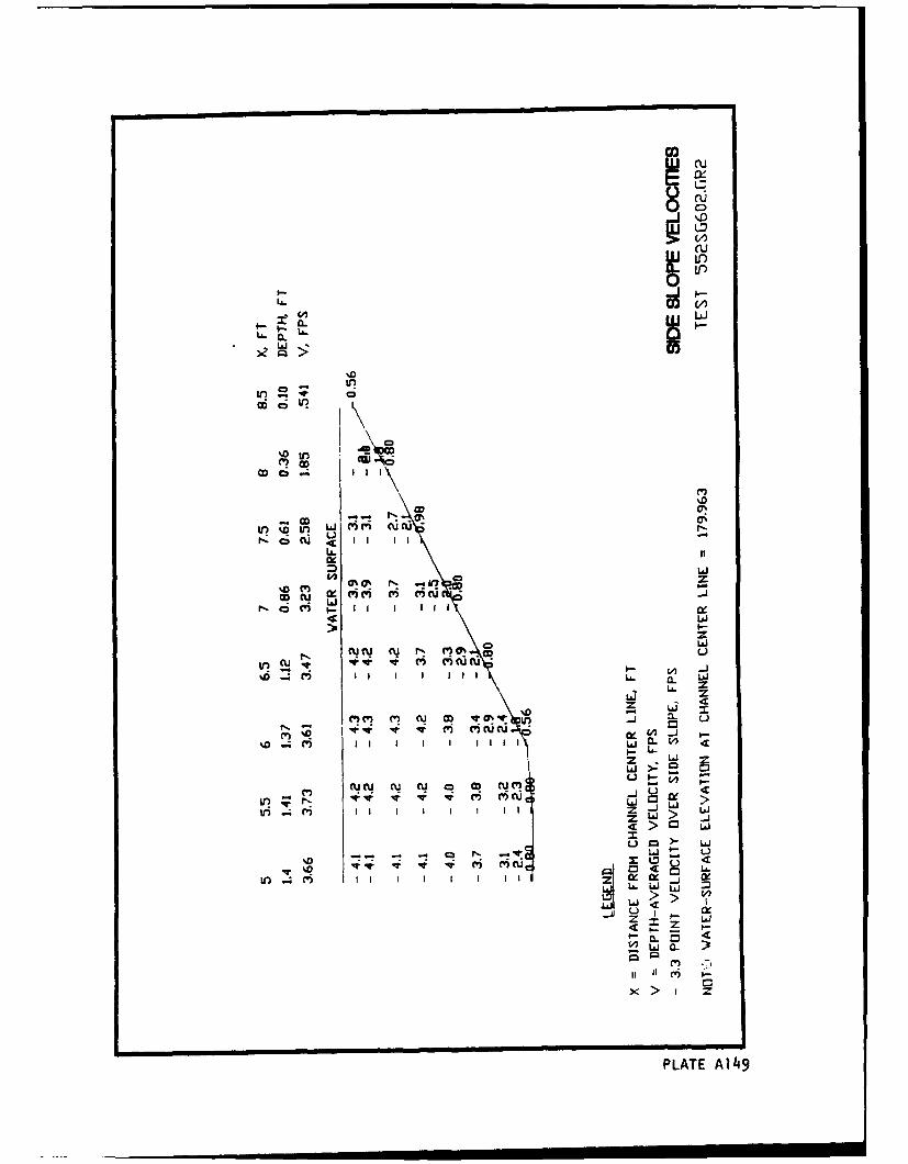
IuCD
LLr)
Ida-4. C LL
KLx gz~
ciIIU\
OD
LL.J
-AJ
(4(' I- CY IIIC 0 O
LA-
0 LLi
(i (U14 CU O -T VuvC
CV) I ILLI L V)
(4C' rN CU a CD U
ri Lj C3 0!~ >~j
m UJ
u~~ow amc C' II I I
> > U
Ui I II w
Laz
x >' I z
PLATE A14,9
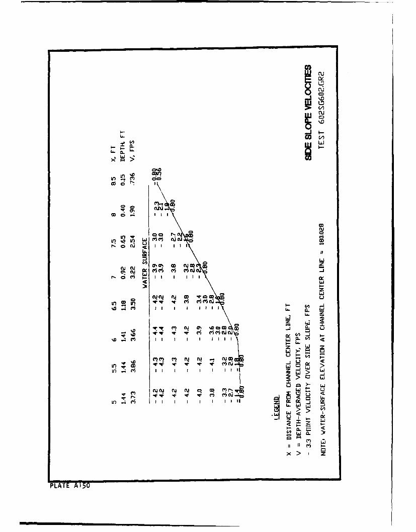
EU
~ 0 r0
CD
0 L0
La6
0
OD a
LO 00 toLa J V u u
II ý I I I I I aQ
LJ>L)
cu cu a.k m mc c
cv A U CU W C 0 CD W'r~
ui z
cv) cv cu c%D~i CV) Iv I ,E-(
PLAT Lai0

CD
CLuCL fl.Uas
~oC?
%D . Il 0I., W f M mCU c to
r, c;Uu~ -oJ
* LaJV-C' C.) CU
,D V Ttd j
U~~~ acr-' 4
z L~i>
Icu c ru ifu CU CO r) CDW L
4n M' =z C')1- 5- A
L.J.
0 4 Li aa
IIx > I I I Z
PLATE A151
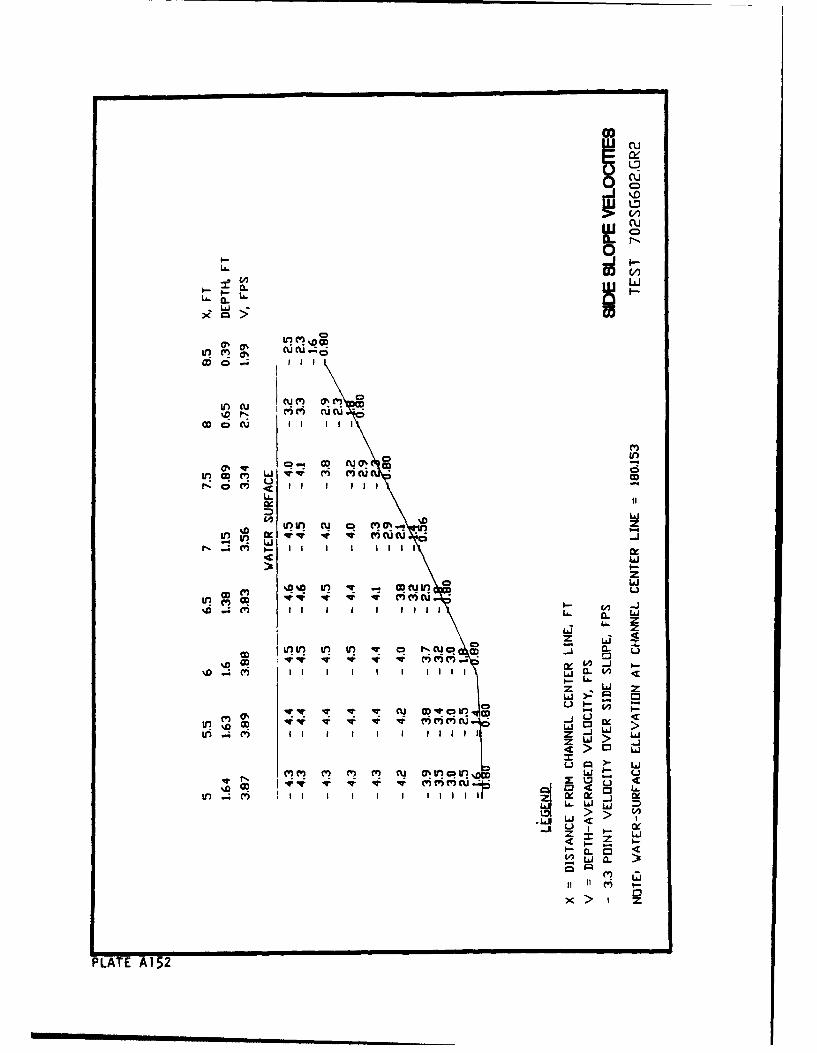
U)00
IIIj
~ocu ii ci
CD
L6.
0%U Cr r? C'ý.- -
r-CD c) II I I C
10 cu mm U
CD Iý CI IlU. a
V) %UIl U) U0 rwCo a
tr)~~~ Ln c c .
z W z
LI IL 11
L6 z
OD C3 I
PLT VAe1W5M2w
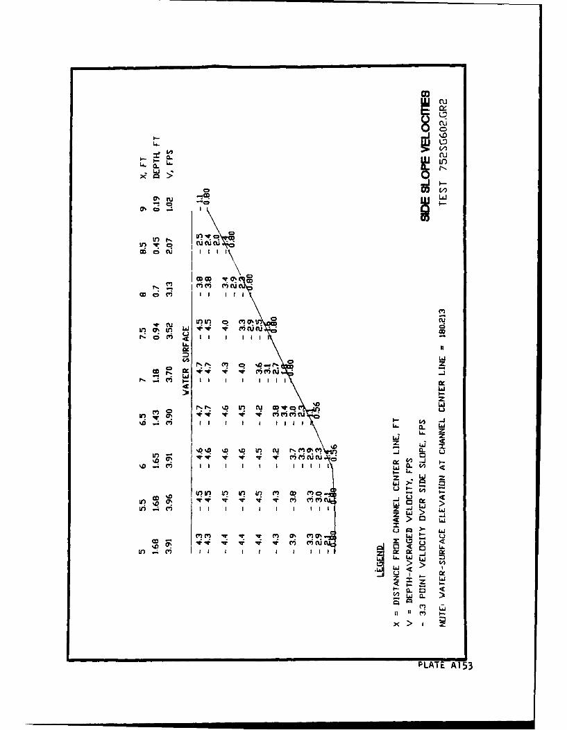
ru
U- 0o
W) Ui v
CD cm (U II I
4Co M )~ o C~O
0. 00 WzVV c
z
at 4 4 4 -4 ri ri a;I-Ix
zr~~~l:~ -La =? C q'tC
mI I I ý j
I L6J z
wL L
V?~Y N. 4, M. C 0% (W) j ( u
z Wo .
0w IV 4 4 4 r, m~C riL ctr l V) I I I I I I I;I Z
>
c w1CV)~~I CV I-I.w s r)v
OD~~~~~LT 4A153q i u U
APPENDIX B: DESCRIPTION OF ROCK MOVEMENT AND FAILURE
Bi
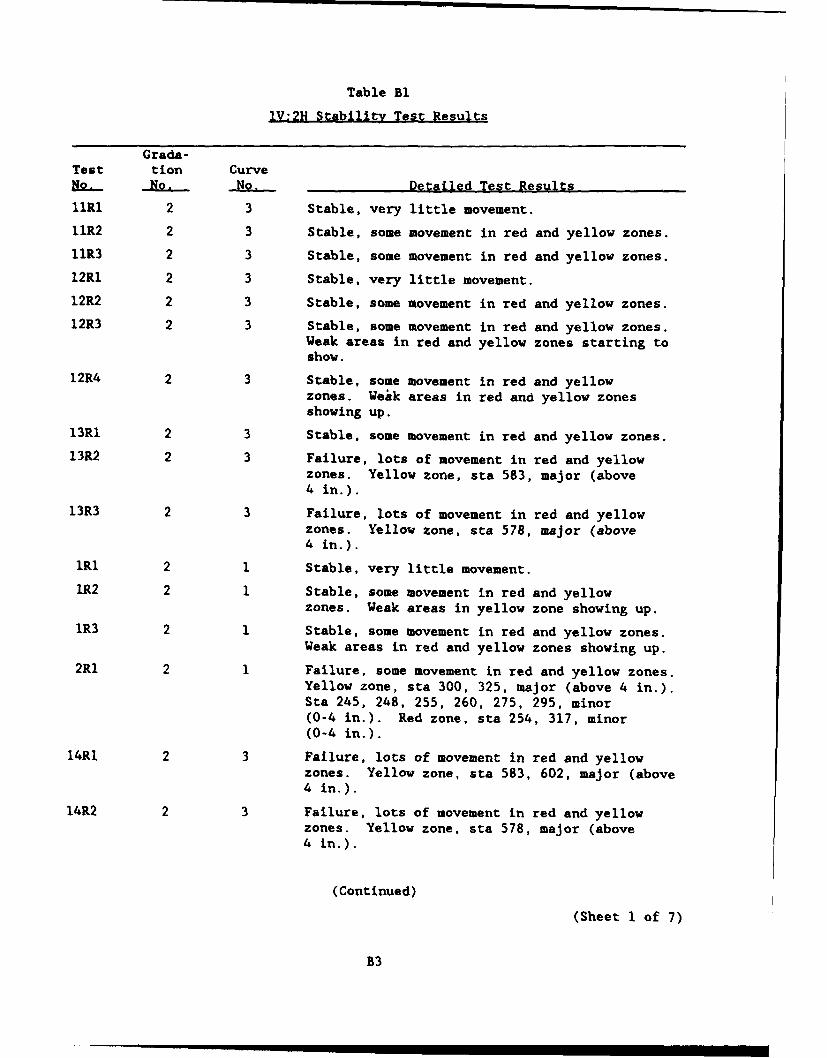
Table Bl
IV:2H Stability Test Results
Grada-Test tion Curve1. -No. No. Detailed Test ResultsllRl 2 3 Stable, very little movement.11R2 2 3 Stable, some movement in red and yellow zones.11R3 2 3 Stable, some movement in red and yellow zones.12R1 2 3 Stable, very little movement.12R2 2 3 Stable, some movement in red and yellow zones.12R3 2 3 Stable, some movement in red and yellow zones.
Weak areas in red and yellow zones starting toshow.
12R4 2 3 Stable, some movement in red and yellowzones. Weak areas in red and yellow zonesshowing up.
13Rl 2 3 Stable, some movement in red and yellow zones.13R2 2 3 Failure, lots of movement in red and yellow
zones. Yellow zone, sta 583, major (above4 in.).
13R3 2 3 Failure, lots of movement in red and yellowzones. Yellow zone, sta 578, major (above4 in.).
lRl 2 1 Stable, very little movement.
lR2 2 1 Stable, some movement in red and yellowzones. Weak areas in yellow zone showing up.
lR3 2 1 Stable, some movement in red and yellow zones.Weak areas in red and yellow zones showing up.
2Rl 2 1 Failure, some movement in red and yellow zones.Yellow zone, sta 300, 325, major (above 4 in.).Sta 245, 248, 255, 260, 275, 295, minor(0-4 in.). Red zone, sta 254, 317, minor(0-4 in.).
14RI 2 3 Failure, lots of movement in red and yellowzones. Yellow zone, sta 583, 602, major (above4 in.).
14R2 2 3 Failure, lots of movement in red and yellowzones. Yellow zone, sta 578, major (above4 in.).
(Continued)
(Sheet 1 of 7)
B3
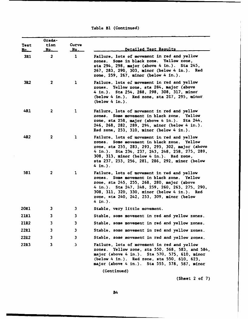
Table Bi (Continued)
Grada-Test tion CurveNo. No. No. Detailed Test Results
3Rl 2 1 Failure, lots of movement in red and yellowzones. Some in black zone. Yellow zone,sta 294, 298, major (above 4 in.). Sta 245,267, 283, 290, 303, minor (below 4 in.). Redzone, 259, 267, minor (below 4 in.).
3R2 2 1 Failure, lots of movement in red and yellowzones. Yellow zone, sta 284, major (above4 in.). Sta 254, 288, 298, 308, 317, minor(below 4 in.). Red zone, sta 2G7, 295, minor(below 4 in.).
4R1 2 1 Failure, lots of movement in red and yellowzones. Some movement in black zone. Yellowzone, sta 258, major (above 4 in.). Sta 244,246, 268, 282, 289, 294, minor (below 4 in.).Red zone, 253, 310, minor (below 4 in.).
4R2 2 1 Failure, lots of movement in red and yellowzones. Some movement in black zone. Yellowzone, sta 255, 283, 293, 295, 302, major (above4 in.). Sta 234, 237, 243, 248, 258, 275, 289,308, 313, minor (below 4 in.). Red zone,sta 237, 253, 256, 281, 286, 292, minor (below4 in.).
5RI 2 1 Failure, lots of movement in red and yellowzones. Some movement in black zone. Yellowzone, sta 245, 255, 268, 280, major (above4 in.). Sta 247, 248, 259, 260, 263, 275, 290,308, 311, 320, 330, minor (below 4 in.). Redzone, sta 240, 242, 253, 309, minor (below4 in.).
20R1 3 3 Stable, very little movement.
21R1 3 3 Stable, some movement in red and yellow zones.
21R2 3 3 Stable, some movement in red and yellow zones.
22R1 3 3 Stable, some movement in red and yellow zones.
22R2 3 3 Stable, some movement in red and yellow zones.
22R3 3 3 Failure, lots of movement in red and yellowzones. Yellow zone, sta 550, 568, 583, and 584,major (above 4 in.). Sta 570, 575, 610, minor(below 4 in.). Red zone, sta 550, 610, 623,major (above 4 in.). Sta 555, 578, 587, minor
(Continued)
(Sheet 2 of 7)
B4
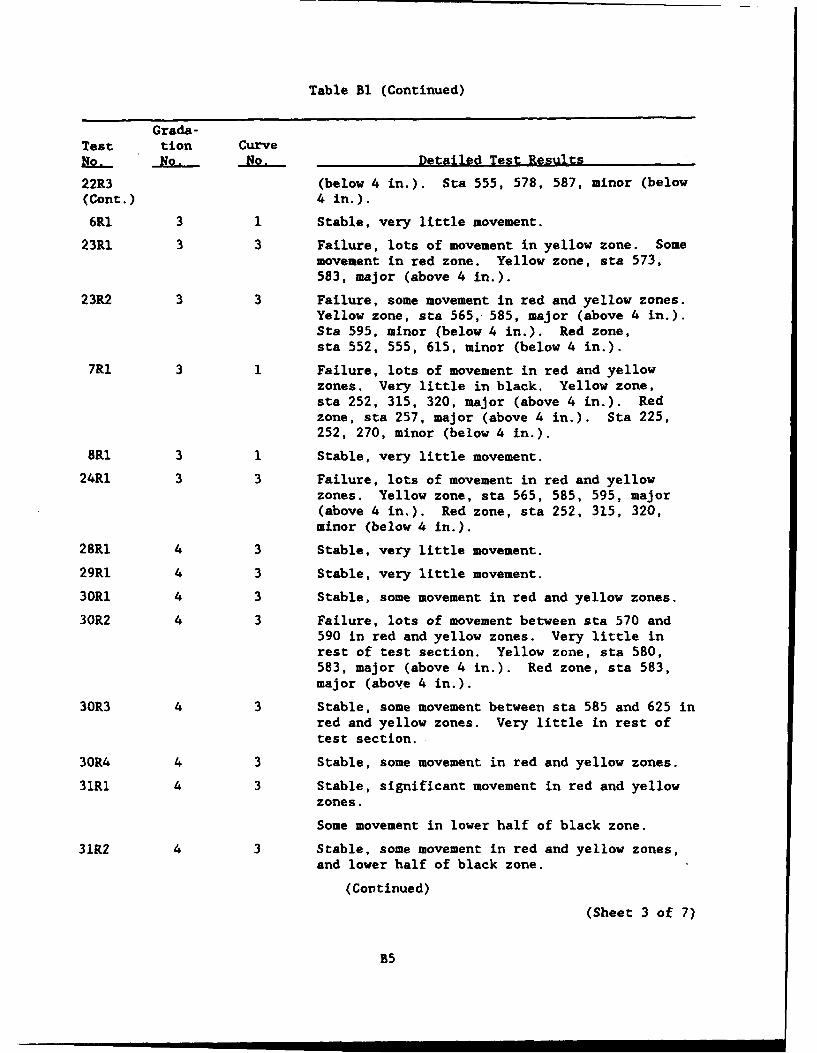
Table Bi (Continued)
Grada-Test tion Curvego, No. No. Detailed Test Results
22R3 (below 4 in.). Sta 555, 578, 587, minor (below(Cont.) 4 in.).
6R1 3 1 Stable, very little movement.
23R1 3 3 Failure, lots of movement in yellow zone. Somemovement in red zone. Yellow zone, sta 573,583, major (above 4 in.).
23R2 3 3 Failure, some movement in red and yellow zones.Yellow zone, sta 565, 585, major (above 4 in.).Sta 595, minor (below 4 in.). Red zone,sta 552, 555, 615, minor (below 4 in.).
7RI 3 1 Failure, lots of movement in red and yellowzones. Very little in black. Yellow zone,sta 252, 315, 320, major (above 4 in.). Redzone, sta 257, major (above 4 in.). Sta 225,252, 270, minor (below 4 in.).
8R1 3 1 Stable, very little movement.
24R1 3 3 Failure, lots of movement in red and yellowzones. Yellow zone, sta 565, 585, 595, major(above 4 in.). Red zone, sta 252, 315, 320,minor (below 4 in.).
28RI 4 3 Stable, very little movement.
29RI 4 3 Stable, very little movement.
30R1 4 3 Stable, some movement in red and yellow zones.
30R2 4 3 Failure, lots of movement between sta 570 and590 in red and yellow zones. Very little inrest of test section. Yellow zone, sta 580,583, major (above 4 in.). Red zone, sta 583,major (above 4 in.).
30R3 4 3 Stable, some movement between sta 585 and 625 inred and yellow zones. Very little in rest oftest section.
30R4 4 3 Stable, some movement in red and yellow zones.
31R1 4 3 Stable, significant movement in red and yellowzones.
Some movement in lower half of black zone.
31R2 4 3 Stable, some movement in red and yellow zones,and lower half of black zone.
(Continued)(Sheet 3 of 7)
B5
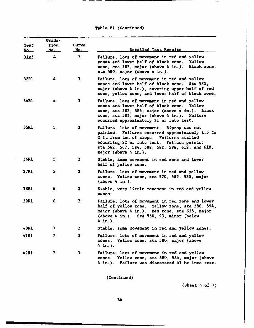
Table BI (Continued)
Grada-Test tion CurveNo. No. No. Detailed Test Results
31R3 4 3 Failure, lots of movement in red and yellowzones and lower half of black zone. Yellowzone, sta 585, major (above 4 in.). Black zone,sta 580, major (above 4 in.).
32R1 4 3 Failure, lots of movement in red and yellowzones and lower half of black zone. Sta 585,major (above 4 in.), covering upper half of redzone, yellow zone, and lower half of black zone.
34R1 4 3 Failure, lots of movement in red and yellowzones and lower half of black zone. Yellowzone, sta 582, 585, major (above 4 in.). Blackzone, sta 585, major (above 4 in.). Failureoccurred approximately 21 hr into test.
35R1 5 3 Failure, lots of movement. Riprap was notpainted. Failures occurred approximately 1.5 to2 ft from toe of slope. Failures startedoccurring 22 hr into test. Failure points:sta 562, 567, 584, 588, 592, 596, 612, and 618,major (above 4 in.).
36R1 5 3 Stable, some movement in red zone and lowerhalf of yellow zone.
37RI 5 3 Failure, lots of movement in red and yellowzones. Yellow zone, sta 570, 582, 585, major(above 4 in.).
38RI 6 3 Stable, very little movement in red and yellowzones.
39R1 6 3 Failure, lots of movement in red zone and lowerhalf of yellow zone. Yellow zone, sta 580, 594,major (above 4 in.). Red zone, sta 615, major(above 4 in.). Sta 550, 93, minor (below4 in.).
40R1 7 3 Stable, some movement in red and yellow zones.
41R1 7 3 Failure, lots of movement in red and yellowzones. Yellow zone, sta 580, major (above4 in.).
42R1 7 3 Failure, lots of movement in red and yellowzones. Yellow zone, sta 580, 584, major (above4 in.). Failure was discovered 41 hr into test.
(Continued)
(Sheet 4 of 7)
B6
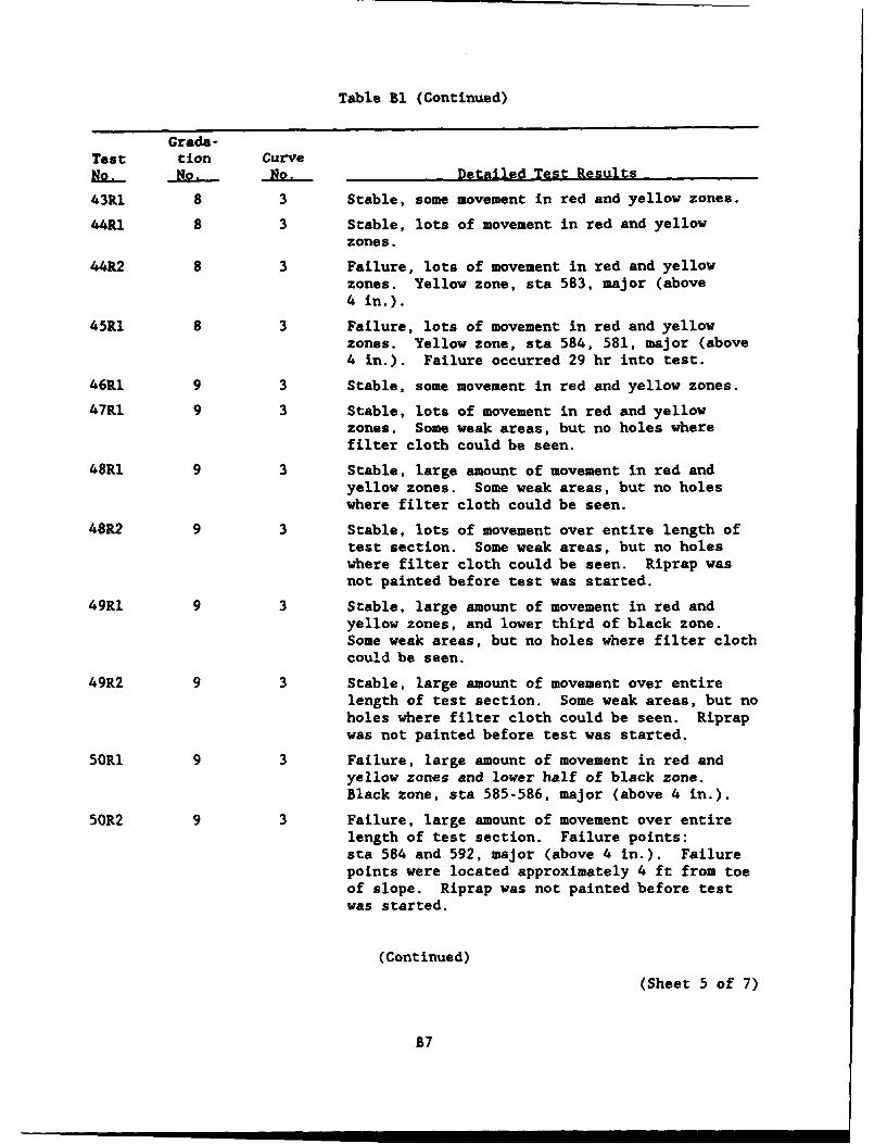
Table B1 (Continued)
Grada-Test tion CurveNo.- NO, No. Detailed Test Results
43R1 8 3 Stable, some movement in red and yellow zones.
44R1 8 3 Stable, lots of movement in red and yellowzones.
44R2 8 3 Failure, lots of movement in red and yellowzones. Yellow zone, sta 583, major (above4 in.).
45R1 8 3 Failure, lots of movement in red and yellowzones. Yellow zone, sta 584, 581, major (above4 in.). Failure occurred 29 hr into test.
46R1 9 3 Stable, some movement in red and yellow zones.
47R1 9 3 Stable, lots of movement in red and yellowzones. Some weak areas, but no holes wherefilter cloth could be seen.
48R1 9 3 Stable, large amount of movement in red andyellow zones. Some weak areas, but no holeswhere filter cloth could be seen.
48R2 9 3 Stable, lots of movement over entire length oftest section. Some weak areas, but no holeswhere filter cloth could be seen. Riprap wasnot painted before test was started.
49R1 9 3 Stable, large amount of movement in red andyellow zones, and lower third of black zone.Some weak areas, but no holes where filter clothcould be seen.
49R2 9 3 Stable, large amount of movement over entirelength of test section. Some weak areas, but noholes where filter cloth could be seen. Riprapwas not painted before test was started.
50RI 9 3 Failure, large amount of movement in red andyellow zones and lower half of black zone.Black zone, sta 585-586, major (above 4 in.).
50R2 9 3 Failure, large amount of movement over entirelength of test section. Failure points:sta 584 and 592, major (above 4 in.). Failurepoints were located approximately 4 ft from toeof slope. Riprap was not painted before testwas started.
(Continued)
(Sheet 5 of 7)
B7
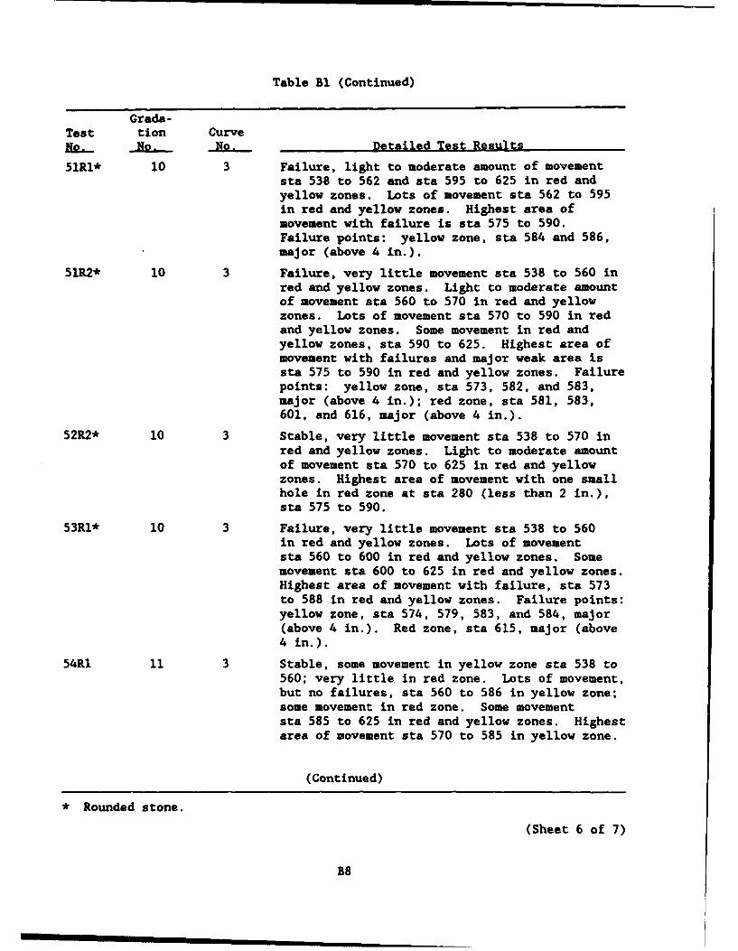
Table Bl (Continued)
Grada-Test tion Curvet..- No. No. Detailed Test Results
51RI* 10 3 Failure, light to moderate amount of movementsta 538 to 562 and sta 595 to 625 in red andyellow zones. Lots of movement sta 562 to 595in red and yellow zones. Highest area ofmovement with failure is sta 575 to 590.Failure points: yellow zone, sta 584 and 586,major (above 4 in.).
51R2* 10 3 Failure, very little movement sta 538 to 560 inred and yellow zones. Light to moderate amountof movement sta 560 to 570 in red and yellowzones. Lots of movement sta 570 to 590 in redand yellow zones. Some movement in red andyellow zones, sta 590 to 625. Highest area ofmovement with failures and major weak area issta 575 to 590 in red and yellow zones. Failurepoints: yellow zone, sta 573, 582, and 583,major (above 4 in.); red zone, sta 581, 583,601, and 616, major (above 4 in.).
52R2* 10 3 Stable, very little movement sta 538 to 570 inred and yellow zones. Light to moderate amountof movement sta 570 to 625 in red and yellowzones. Highest area of movement with one smallhole in red zone at sta 280 (less than 2 in.),sta 575 to 590.
53R1* 10 3 Failure, very little movement sta 538 to 560in red and yellow zones. Lots of movementsta 560 to 600 in red and yellow zones. Somemovement sta 600 to 625 in red and yellow zones.Highest area of movement with failure, sta 573to 588 in red and yellow zones. Failure points:yellow zone, sta 574, 579, 583, and 584, major(above 4 in.). Red zone, sta 615, major (above4 in.).
54R1 11 3 Stable, some movement in yellow zone sta 538 to560; very little in red zone. Lots of movement,but no failures, sta 560 to 586 in yellow zone;some movement in red zone. Some movementsta 585 to 625 in red and yellow zones. Highestarea of movement sta 570 to 585 in yellow zone.
(Continued)
• Rounded stone.
(Sheet 6 of 7)
B8
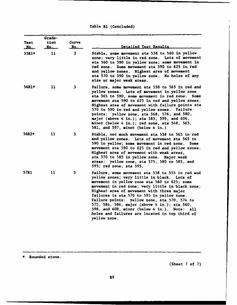
Table Bl (Concluded)
Grada-Test tion Curve
No. No. No. Detailed Test Results
55RI* 11 3 Stable, some movement sta 538 to 560 in yellowzone; very little in red zone. Lots of movementsta 560 to 590 in yellow zone; some movement inred zone. Some movement sta 590 to 625 in redand yellow zones. Highest area of movementsta 570 to 590 in yellow zone. No holes of anysize or major weak areas.
56R1* 11 3 Failure, some movement sta 538 to 565 in red andyellow zones. Lots of movement in yellow zonesta 565 to 590, some movement in red zone. Somemovement sta 590 to 625 in red and yellow zones.Highest area of movement with failure points sta570 to 590 in red and yellow zones. Failurepoints: yellow zone, sta 568, 576, and 580,major (above 4 in.); sta 585, 599, and 606,minor (below 4 in.); red zone, sta 548, 565,581, and 597, minor (below 4 in.)
56R2* 11 3 Stable, not much movement sta 538 to 565 in redand yellow zones. Lots of movement sta 565 to590 in yellow; some movement in red zone. Somemovement sta 590 to 625 in red and yellow zones.Highest area of movement with weak areas,sta 570 to 585 in yellow zone. Major weakareas: yellow zone, sta 575, 580 to 585, and595; red zone, sta 595.
57R1 11 3 Failure, some movement sta 538 to 555 in red andyellow zones; very little in black. Lots ofmovement in yellow zone sta 560 to 625; somemovement in red zone; very little in black zone.Highest area of movement with three majorfailures is sta 570 to 595 in yellow zone.Failure points: yellow zone, sta 570, 574 to575, 584, 586, major (above 4 in.); sta 560,598, and 608, minor (below 4 in.). Note: allholes and failures are located in top third ofyellow zone.
* Rounded stone.
(Sheet 7 of 7)
B9
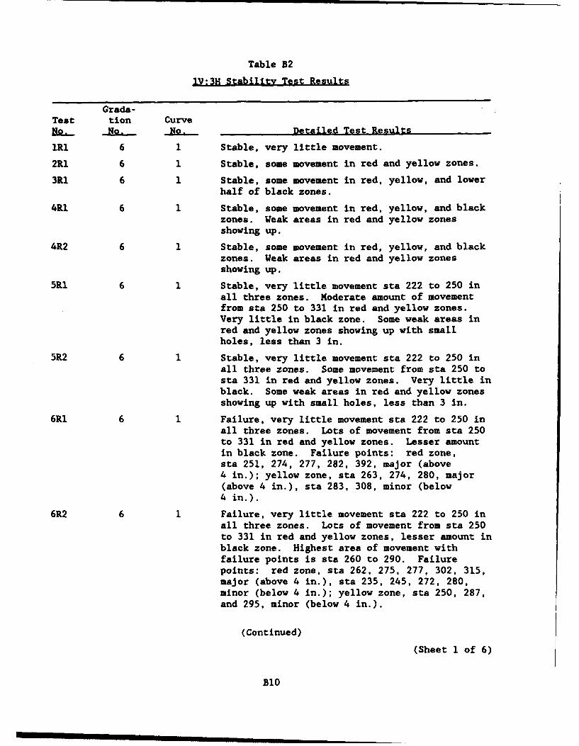
Table B2
lV:3H Stability Test Results
Grada-Test tion CurveNo. No. No. Detailed Test Results
1RI 6 1 Stable, very little movement.
2R1 6 1 Stable, some movement in red and yellow zones.
3R1 6 1 Stable, some movement in red, yellow, and lowerhalf of black zones.
4R1 6 1 Stable, some movement in red, yellow, and blackzones. Weak areas in red and yellow zonesshowing up.
4R2 6 1 Stable, some movement in red, yellow, and blackzones. Weak areas in red and yellow zonesshowing up.
5R1 6 1 Stable, very little movement sta 222 to 250 inall three zones. Moderate amount of movementfrom sta 250 to 331 in red and yellow zones.Very little in black zone. Some weak areas inred and yellow zones showing up with smallholes, less than 3 in.
5R2 6 1 Stable, very little movement sta 222 to 250 inall three zones. Some movement from sta 250 tosta 331 in red and yellow zones. Very little inblack. Some weak areas in red and yellow zonesshowing up with small holes, less than 3 in.
6RI 6 1 Failure, very little movement sta 222 to 250 inall three zones. Lots of movement from sta 250to 331 in red and yellow zones. Lesser amountin black zone. Failure points: red zone,sta 251, 274, 277, 282, 392, major (above4 in.); yellow zone, sta 263, 274, 280, major(above 4 in.), sta 283, 308, minor (below4 in.).
6R2 6 1 Failure, very little movement sta 222 to 250 inall three zones. Lots of movement from sta 250to 331 in red and yellow zones, lesser amount inblack zone. Highest area of movement withfailure points is sta 260 to 290. Failurepoints: red zone, sta 262, 275, 277, 302, 315,major (above 4 in.), sta 235, 245, 272, 280,minor (below 4 in.); yellow zone, sta 250, 287,and 295, minor (below 4 in.).
(Continued)
(Sheet 1 of 6)
B10
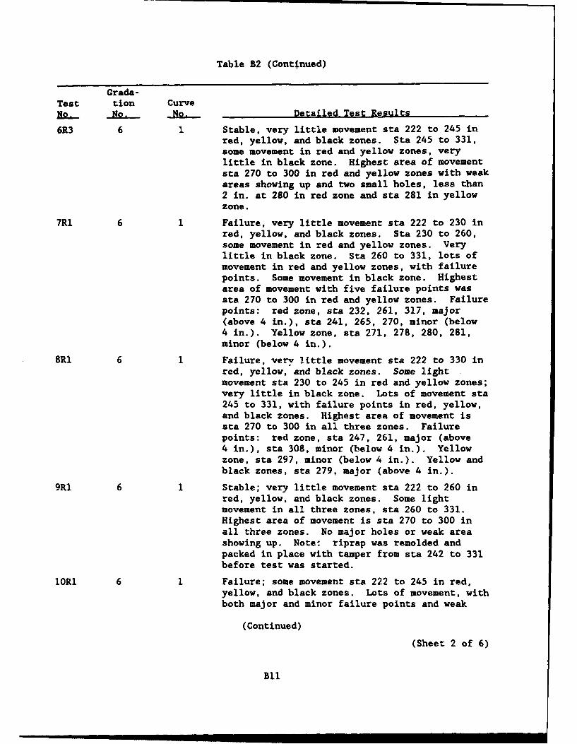
Table B2 (Continued)
Grada-Test tion CurveN.. No. No. Detailed Test Results
6R3 6 1 Stable, very little movement sta 222 to 245 inred, yellow, and black zones. Sta 245 to 331,some movement in red and yellow zones, verylittle in black zone. Highest area of movementsta 270 to 300 in red and yellow zones with weakareas showing up and two small holes, less than2 in. at 280 in red zone and sta 281 in yellowzone.
7Rl 6 1 Failure, very little movement sta 222 to 230 inred, yellow, and black zones. Sta 230 to 260,some movement in red and yellow zones. Verylittle in black zone. Sta 260 to 331, lots ofmovement in red and yellow zones, with failurepoints. Some movement in black zone. Highestarea of movement with five failure points wassta 270 to 300 in red and yellow zones. Failurepoints: red zone, sta 232, 261, 317, major(above 4 in.), sta 241, 265, 270, minor (below4 in.). Yellow zone, sta 271, 278, 280, 281,minor (below 4 in.).
8R1 6 1 Failure, very little movement sta 222 to 330 inred, yellow, and black zones. Some lightmovement sta 230 to 245 in red and yellow zones;very little in black zone. Lots of movement sta245 to 331, with failure points in red, yellow,and black zones. Highest area of movement issta 270 to 300 in all three zones. Failurepoints: red zone, sta 247, 261, major (above4 in.), sta 308, minor (below 4 in.). Yellowzone, sta 297, minor (below 4 in.). Yellow andblack zones, sta 279, major (above 4 in.).
9R1 6 1 Stable; very little movement sta 222 to 260 inred, yellow, and black zones. Some lightmovement in all three zones, sta 260 to 331.Highest area of movement is sta 270 to 300 inall three zones. No major holes or weak areashowing up. Note: riprap was remolded andpacked in place with tamper from sta 242 to 331before test was started.
1OR1 6 1 Failure; some movement sta 222 to 245 in red,yellow, and black zones. Lots of movement, withboth major and minor failure points and weak
(Continued)
(Sheet 2 of 6)
Bll
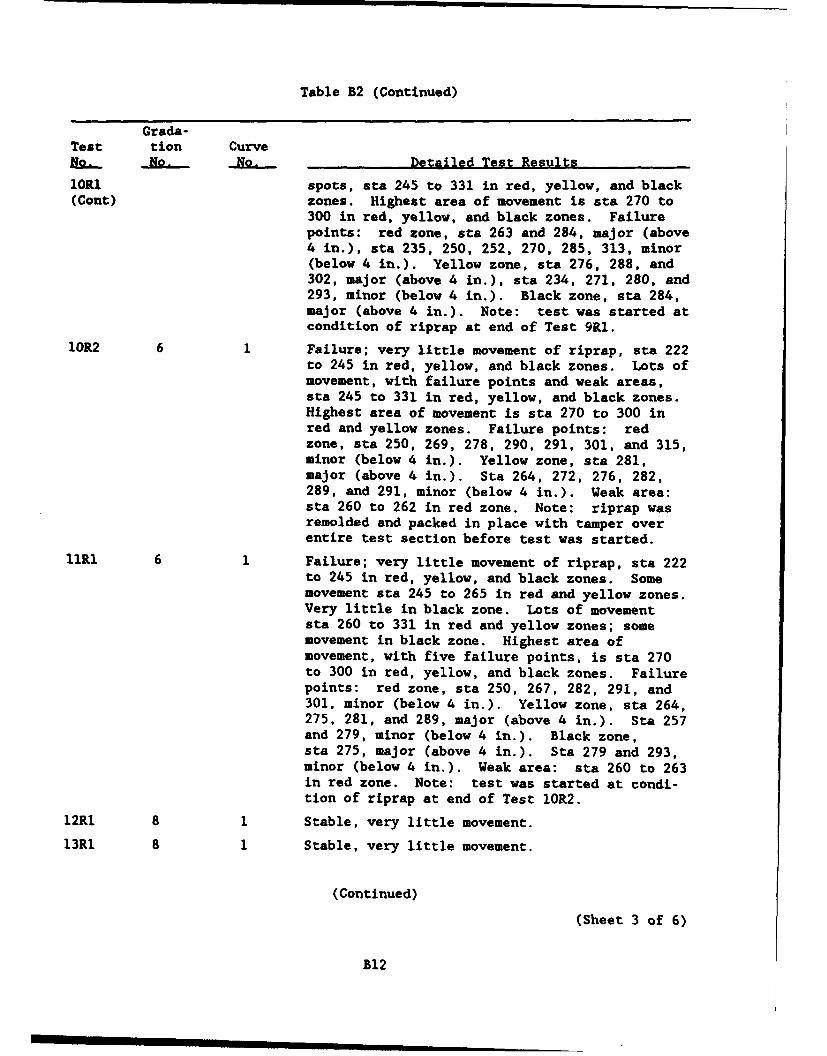
Table B2 (Continued)
Grada-Test tion CurveN. N. N. Detailed Test Results
lORI spots, sta 245 to 331 in red, yellow, and black(Cont) zones. Highest area of movement is sta 270 to
300 in red, yellow, and black zones. Failurepoints: red zone, sta 263 and 284, major (above4 in.), sta 235, 250, 252, 270, 285, 313, minor(below 4 in.). Yellow zone, sta 276, 288, and302, major (above 4 in.), sta 234, 271, 280, and293, minor (below 4 in.). Black zone, sta 284,major (above 4 in.). Note: test was started atcondition of riprap at end of Test 9M1.
10R2 6 1 Failure; very little movement of riprap, sta 222to 245 in red, yellow, and black zones. Lots ofmovement, with failure points and weak areas,sta 245 to 331 in red, yellow, and black zones.Highest area of movement is sta 270 to 300 inred and yellow zones. Failure points: redzone, sta 250, 269, 278, 290, 291, 301, and 315,minor (below 4 in.). Yellow zone, sta 281,major (above 4 in.). Sta 264, 272, 276, 282,289, and 291, minor (below 4 in.). Weak area:sta 260 to 262 in red zone. Note: riprap wasremolded and packed in place with tamper overentire test section before test was started.
llRI 6 1 Failure; very little movement of riprap, sta 222to 245 in red, yellow, and black zones. Somemovement sta 245 to 265 in red and yellow zones.Very little in black zone. Lots of movementsta 260 to 331 in red and yellow zones; somemovement in black zone. Highest area ofmovement, with five failure points, is sta 270to 300 in red, yellow, and black zones. Failurepoints: red zone, sta 250, 267, 282, 291, and301, minor (below 4 in.). Yellow zone, sta 264,275, 281, and 289, major (above 4 in.). Sta 257and 279, minor (below 4 in.). Black zone,sta 275, major (above 4 in.). Sta 279 and 293,minor (below 4 in.). Weak area: sta 260 to 263in red zone. Note: test was started at condi-tion of riprap at end of Test 10R2.
12R1 8 1 Stable, very little movement.
13R1 8 1 Stable, very little movement.
(Continued)
(Sheet 3 of 6)
B12
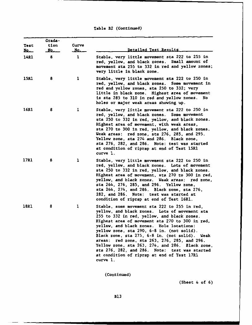
Table B2 (Continued)
Grada-Test tion CurveE.. No. No. Detailed TestResults
14R1 8 1 Stable, very little movement sta 222 to 255 inred, yellow, and black zones. Small amount ofmovement sta 255 to 332 in red and yellow zones;very little in black zone.
15R1 8 1 Stable, very little movement sta 222 to 250 inred, yellow, and black zones. Some movement inred and yellow zones, sta 250 to 332; verylittle in black zone. Highest area of movementis sta 285 to 310 in red and yellow zones. Noholes or major weak areas showing up.
16R1 8 1 Stable, very little movement sta 222 to 250 inred, yellow, and black zones. Some movementsta 250 to 332 in red, yellow, and black zones.Highest area of movement, with weak areas,sta 270 to 300 in red, yellow, and black zones.Weak areas: red zone, sta 276, 285, and 295.Yellow zone, sta 274 and 286. Black zone,sta 276, 282, and 286. Note: test was startedat condition of riprap at end of Test 15R1curve 1.
17R1 8 1 Stable, very little movement sta 222 to 250 inred, yellow, and black zones. Lots of movementsta 250 to 332 in red, yellow, and black zones.Highest area of movement, sta 270 to 300 in red,yellow, and black zones. Weak areas: red zone,sta 264, 276, 285, and 296. Yellow zone,sta 264, 274, and 286. Black zone, sta 276,282, and 286. Note: test was started atcondition of riprap at end of Test 16RI.
18R1 8 1 Stable, some movement sta 222 to 255 in red,yellow, and black zones. Lots of movement sta255 to 332 in red, yellow, and black zones.Highest area of movement sta 270 to 300 in red,yellow, and black zones. Hole locations:yellow zone, sta 290, 6-8 in. (not solid).Black zone, sta 275, 6-8 in. (not solid). Weakareas: red zone, sta 263, 276, 285, and 296.Yellow zone, sta 263, 274, and 286. Black zone,sta 276, 282, and 286. Note: test was startedat condition of riprap at end of Test 17R1curve 1.
(Continued)
(Sheet 4 of 6)
B13
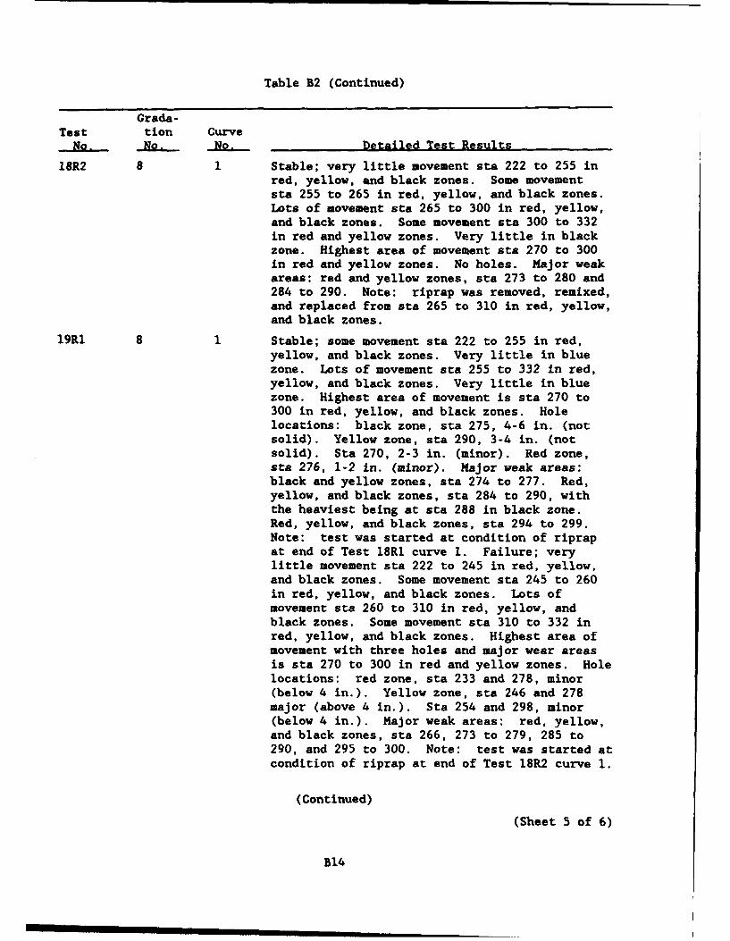
Table B2 (Continued)
Grada-Test tion Curve
No. No. No. Detailed Test Results
18R2 8 1 Stable; very little movement sta 222 to 255 inred, yellow, and black zones. Some movementsta 255 to 265 in red, yellow, and black zones.Lots of movement sta 265 to 300 in red, yellow,and black zones. Some movement sta 300 to 332in red and yellow zones. Very little in blackzone. Highest area of movement sta 270 to 300in red and yellow zones. No holes. Major weakareas: red and yellow zones, sta 273 to 280 and284 to 290. Note: riprap was removed, remixed,and replaced from sta 265 to 310 in red, yellow,and black zones.
19R1 8 1 Stable; some movement sta 222 to 255 in red,yellow, and black zones. Very little in bluezone. Lots of movement sta 255 to 332 in red,yellow, and black zones. Very little in bluezone. Highest area of movement is sta 270 to300 in red, yellow, and black zones. Holelocations: black zone, sta 275, 4-6 in. (notsolid). Yellow zone, sta 290, 3-4 in. (notsolid). Sta 270, 2-3 in. (minor). Red zone,sta 276, 1-2 in. (minor). Major weak areas:black and yellow zones, sta 274 to 277. Red,yellow, and black zones, sta 284 to 290, withthe heaviest being at sta 288 in black zone.Red, yellow, and black zones, sta 294 to 299.Note: test was started at condition of riprapat end of Test 18R1 curve 1. Failure; verylittle movement sta 222 to 245 in red, yellow,and black zones. Some movement sta 245 to 260in red, yellow, and black zones. Lots ofmovement sta 260 to 310 in red, yellow, andblack zones. Some movement sta 310 to 332 inred, yellow, and black zones. Highest area ofmovement with three holes and major wear areasis sta 270 to 300 in red and yellow zones. Holelocations: red zone, sta 233 and 278, minor(below 4 in.). Yellow zone, sta 246 and 278major (above 4 in.). Sta 254 and 298, minor(below 4 in.). Major weak areas: red, yellow,and black zones, sta 266, 273 to 279, 285 to290, and 295 to 300. Note: test was started atcondition of riprap at end of Test 18R2 curve 1.
(Continued)(Sheet 5 of 6)
B14
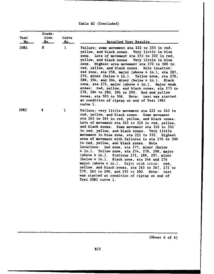
Table B2 (Concluded)
Grada-Test tion Curve
No. No. No. Detailed Test Results
20Rl 8 1 Failure; some movement sta 222 to 255 in red,yellow, and black zones. Very little in bluezone. Lots of movement sta 255 to 332 in red,yellow, and black zones. Very little in bluezone. Highest area movement sta 270 to 300 inred, yellow, and black zones. Hole location:red zone, sta 258, major (above 4 in.), sta 287,270, minor (below 4 in.). Yellow zone, sta 270,288, 294, and 304, minor (below 4 in.). Blackzone, sta 275, major (above 4 in.). Major weakareas: red, yellow, and black zones, sta 273 to278, 284 to 290, 294 to 299. Red and yellowzones, sta 303 to 306. Note: test was startedat condition of riprap at end of Test 19R1curve 1.
20R2 8 1 Failure; very little movement sta 222 to 245 inred, yellow, and black zones. Some movementsta 245 to 265 in red, yellow, and black zones.Lots of movement sta 265 to 310 in red, yellow,and black zones. Some movement sta 310 to 332in red, yellow, and black zones. Very littlemovement in blue zone, sta 222 to 332. Highestarea of movement with failures is sta 270 to 300in red, yellow, and black zones. Holelocations: red zone, sta 277, minor (below4 in.). Yellow zone, sta 274, 278, 298, major(above 4 in.). Stations 271, 288, 297, minor(below 4 in.). Black zone, sta 246 and 276major (above 4 in.). Major weak areas: red,yellow, and black zones, sta 265 to 267, 272 to279, 285 to 290, and 295 to 300. Note: testwas started at condition of riprap at end ofTest 20R1 curve 1.
(Sheet 6 of 6)
B15
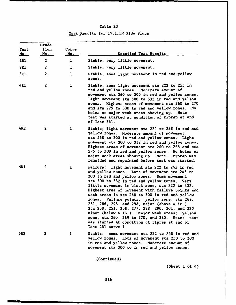
Table B3
Test Results for 1V:l.5H Side Slope
Grada-Test tion CurveNo. No. No. Detailed Test Results
IRI 2 1 Stable, very little movement.
2R1 2 1 Stable, very little movement.
3Rl 2 1 Stable, some light movement in red and yellowzones.
4R1 2 1 Stable, some light movement sta 222 to 255 inred and yellow zones. Moderate amount ofmovement sta 260 to 300 in red and yellow zones.Light movement sta 300 to 332 in red and yellowzones. Highest areas of movement sta 260 to 270and sta 275 to 300 in red and yellow zones. Noholes or major weak areas showing up. Note:test was started at condition of riprap at endof Test 3R1.
4R2 2 1 Stable; light movement sta 222 to 258 in red andyellow zones. Moderate amount of movementsta 258 to 300 in red and yellow zones. Lightmovement sta 300 to 332 in red and yellow zones.Highest areas of movement sta 260 to 265 and sta275 to 300 in red and yellow zones. No holes ormajor weak areas showing up. Note: riprap wasremolded and repainted before test was started.
5RI 2 1 Failure: light movement sta 222 to 245 in redand yellow zones. Lots of movement sta 245 to300 in red and yellow zones. Some movementsta 300 to 332 in red and yellow zones. Verylittle movement in black zone, sta 222 to 332.Highest area of movement with failure points andweak areas is sta 260 to 300 in red and yellowzones. Failure points: yellow zone, sta 269,281, 286, 295, and 298, major (above 4 in.).Sta 250, 251, 258, 277, 288, 290, 301, and 320,minor (below 4 in.). Major weak areas: yellowzone, sta 260, 269 to 270, and 280. Note: testwas started at condition of riprap at end ofTest 4R1 curve 1.
5R2 2 1 Stable: some movement sta 222 to 250 in red andyellow zones. Lots of movement sta 250 to 300in red and yellow zones. Moderate amount ofmovement sta 300 to in red and yellow zones.
(Continued)
(Sheet 1 of 4)
B16
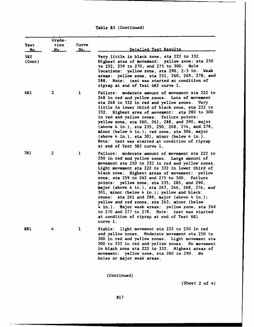
Table B3 (Continued)
Grada-Test tion Curve
No. Nio. No. Detailed Test Results
5R2 Very little in black zone, sta 222 to 332.(Cont) Highest area of movement: yellow zone; sta 250
to 252, 259 to 270, and 275 to 300. Holelocations: yellow zone, sta 290, 2-3 in. Weakareas: yellow zone, sta 251, 260, 269, 278, and288. Note: test was started at condition ofriprap at end of Test 4R2 curve 1.
6RI 2 1 Failure: moderate amount of movement sta 222 to248 in red and yellow zones. Lots of movementsta 248 to 332 in red and yellow zones. Verylittle in lower third of black zone, sta 222 to332. Highest area of movement: sta 280 to 300in red and yellow zones. Failure points:yellow zone, sta 260, 261, 288, and 290, major(above 4 in.), sta 235, 250, 268, 274, and 278,minor (below 4 in.); red zone, sta 306, major(above 4 in.), sta 301, minor (below 4 in.).Note: test was started at condition of riprapat end of Test 5R2 curve 1.
7RI 2 Failure: moderate amount of movement sta 222 to250 in red and yellow zones. Large amount ofmovement sta 250 to 332 in red and yellow zones.Light movement sta 222 to 332 in lower third ofblack zone. Highest areas of movement: yellowzone, sta 259 to 262 and 275 to 300. Failurepoints: yellow zone, sta 235, 285, and 290,major (above 4 in.), sta 263, 266, 268, 274, and301, minor (below 4 in.); yellow and blackzones: sta 261 and 288, major (above 4 in.);yellow and red zones, sta 263, minor (below4 in.). Major weak areas: yellow zone, sta 268to 270 and 277 to 278. Note: test was startedat condition of riprap at end of Test 6RIcurve 1.
8RI 4 1 Stable: light movement sta 222 to 250 in redand yellow zones. Moderate movement sta 250 to300 in red and yellow zones. Light movement sta300 to 332 in red and yellow zones. No movementin black zone sta 222 to 332. Highest areas ofmovement: yellow zone, sta 260 to 290. Noholes or major weak areas.
(Continued)(Sheet 2 of 4)
B17
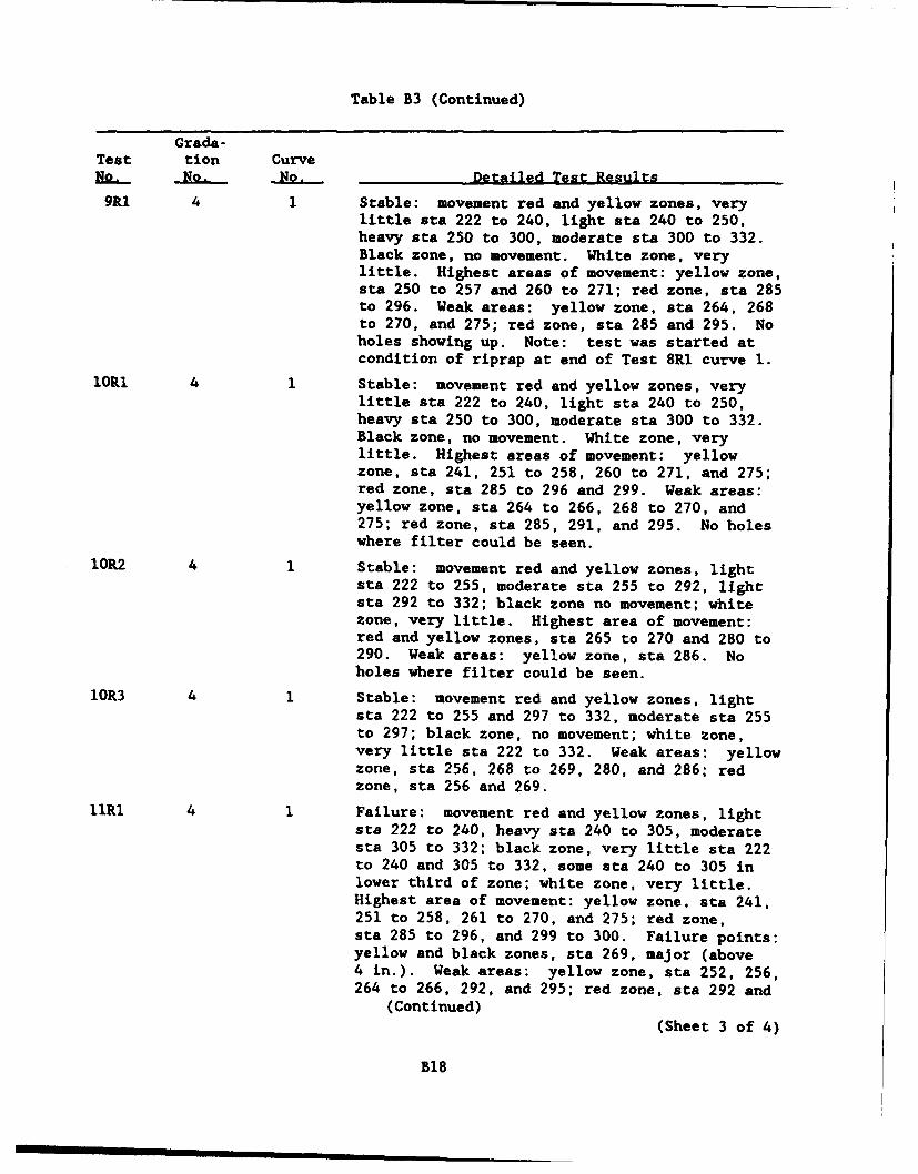
Table B3 (Continued)
Grada-Test tion CurveR- No. No. Detailed Test Results
9R1 4 1 Stable: movement red and yellow zones, verylittle sta 222 to 240, light sta 240 to 250,heavy sta 250 to 300, moderate sta 300 to 332.Black zone, no movement. White zone, verylittle. Highest areas of movement: yellow zone,sta 250 to 257 and 260 to 271; red zone, sta 285to 296. Weak areas: yellow zone, sta 264, 268to 270, and 275; red zone, sta 285 and 295. Noholes showing up. Note: test was started atcondition of riprap at end of Test 8Ri curve 1.
lORl 4 1 Stable: movement red and yellow zones, verylittle sta 222 to 240, light sta 240 to 250,heavy sta 250 to 300, moderate sta 300 to 332.Black zone, no movement. White zone, verylittle. Highest areas of movement: yellowzone, sta 241, 251 to 258, 260 to 271, and 275;red zone, sta 285 to 296 and 299. Weak areas:yellow zone, sta 264 to 266, 268 to 270, and275; red zone, sta 285, 291, and 295. No holeswhere filter could be seen.
10R2 4 1 Stable: movement red and yellow zones, lightsta 222 to 255, moderate sta 255 to 292, lightsta 292 to 332; black zone no movement; whitezone, very little. Highest area of movement:red and yellow zones, sta 265 to 270 and 280 to290. Weak areas: yellow zone, sta 286. Noholes where filter could be seen.
1OR3 4 1 Stable: movement red and yellow zones, lightsta 222 to 255 and 297 to 332, moderate sta 255to 297; black zone, no movement; white zone,very little sta 222 to 332. Weak areas: yellowzone, sta 256, 268 to 269, 280, and 286; redzone, sta 256 and 269.
llRl 4 1 Failure: movement red and yellow zones, lightsta 222 to 240, heavy sta 240 to 305, moderatesta 305 to 332; black zone, very little sta 222to 240 and 305 to 332, some sta 240 to 305 inlower third of zone; white zone, very little.Highest area of movement: yellow zone, sta 241,251 to 258, 261 to 270, and 275; red zone,sta 285 to 296, and 299 to 300. Failure points:yellow and black zones, sta 269, major (above4 in.). Weak areas: yellow zone, sta 252, 256,264 to 266, 292, and 295; red zone, sta 292 and
(Continued)(Sheet 3 of 4)
B18
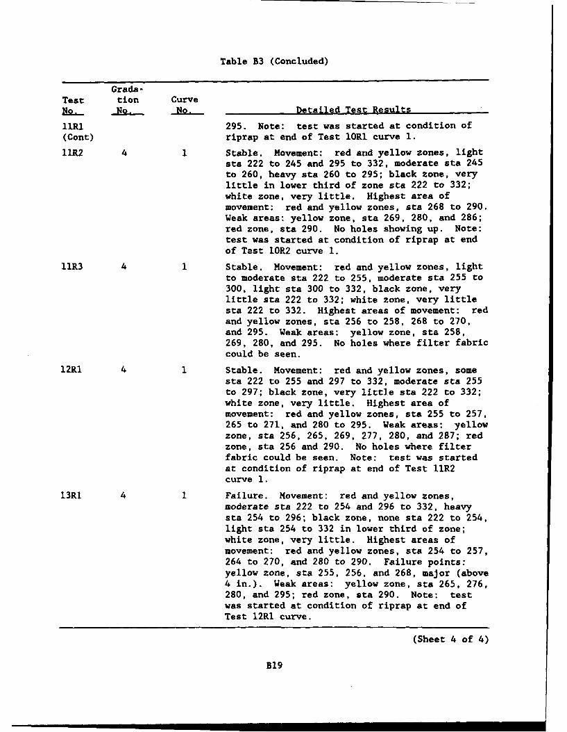
Table B3 (Concluded)
Grade-Test tion CurveNo. No. No. Detailed Test Results
lIRI 295. Note: test was started at condition of(Cont) riprap at end of Test 1OR1 curve 1.
11R2 4 1 Stable. Movement: red and yellow zones, lightsta 222 to 245 and 295 to 332, moderate sta 245to 260, heavy sta 260 to 295; black zone, verylittle in lower third of zone sta 222 to 332;white zone, very little. Highest area ofmovement: red and yellow zones, sta 268 to 290.Weak areas: yellow zone, sta 269, 280, and 286;red zone, sta 290. No holes showing up. Note:test was started at condition of riprap at endof Test 10R2 curve 1.
11R3 4 1 Stable. Movement: red and yellow zones, lightto moderate sta 222 to 255, moderate sta 255 to300, light sta 300 to 332, black zone, verylittle sta 222 to 332; white zone, very littlesta 222 to 332. Highest areas of movement: redand yellow zones, sta 256 to 258, 268 to 270,and 295. Weak areas: yellow zone, sta 258,269, 280, and 295. No holes where filter fabriccould be seen.
12RI 4 1 Stable. Movement: red and yellow zones, somesta 222 to 255 and 297 to 332, moderate sta 255to 297; black zone, very little sta 222 to 332;white zone, very little. Highest area ofmovement: red and yellow zones, sta 255 to 257,265 to 271, and 280 to 295. Weak areas: yellowzone, sta 256, 265, 269, 277, 280, and 287; redzone, sta 256 and 290. No holes where filterfabric could be seen. Note: test was startedat condition of riprap at end of Test 1IR2curve 1.
13R1 4 1 Failure. Movement: red and yellow zones,moderate sta 222 to 254 and 296 to 332, heavysta 254 to 296; black zone, none sta 222 to 254,light sta 254 to 332 in lower third of zone;white zone, very little. Highest areas ofmovement: red and yellow zones, sta 254 to 257,264 to 270, and 280 to 290. Failure points:yellow zone, sta 255, 256, and 268, major (above4 in.). Weak areas: yellow zone, sta 265, 276,280, and 295; red zone, sta 290. Note: testwas started at condition of riprap at end ofTest 12R1 curve.
(Sheet 4 of 4)
B19
S.. . = ' l I I I I
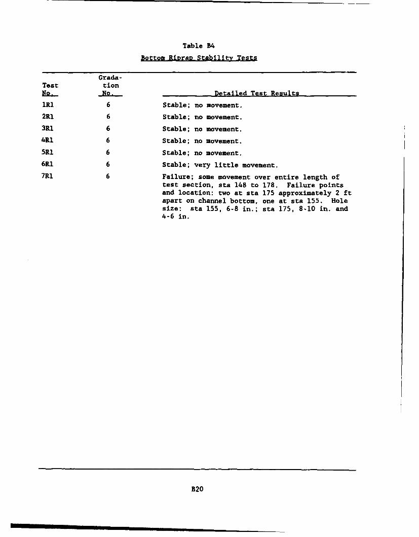
Table B4
Bottom R12ra2 Stability Tests
Grada-Test tionN2.- No. ,~Detailed Test Results
lRl 6 Stable; no movement.
2R1 6 Stable; no movement.
3Rl 6 Stable; no movement.
4R1 6 Stable; no movement.
5R1 6 Stable; no movement.
6R1 6 Stable; very little movement.
7RI 6 Failure; some movement over entire length oftest section, sta 148 to 178. Failure pointsand location: two at sta 175 approximately 2 ftapart on channel bottom, one at sta 155. Holesize: sta 155, 6-8 in.; sta 175, 8-10 in. and4-6 in.
B20
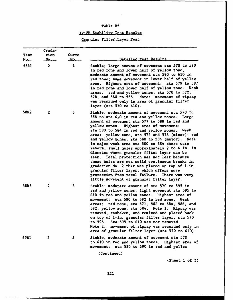
Table B5
IV:2H Stability Test Results
Granular Filter Layer Test
Grada-Test tion CurveB2.. No. No. Detailed Test Results
58R1 2 3 Stable; large amount of movement sta 570 to 590in red zone and lower half of yellow zone,moderate amount of movement sta 590 to 610 inred zone; some movement in lower half of yellowzone. Highest area of movement: sta 579 to 587in red zone and lower half of yellow zone. Weakareas: red and yellow zones, sta 570 to 572,578, and 580 to 585. Note: movement of riprapwas recorded only in area of granular filterlayer (sta 570 to 610).
58R2 2 3 Stable; moderate amount of movement sta 570 to588 to sta 610 in red and yellow zones. Largeamount of movement sta 577 to 588 in red andyellow zones. Highest area of movement:sta 580 to 584 in red and yellow zones. Weakarea: yellow zone, sta 575 and 578 (minor); redand yellow zones, sta 580 to 584 (major). Note:in major weak area sta 580 to 584 there wereseveral small holes approximately 2 to 4 in. indiameter where granular filter layer can beseen. Total protection was not lost becausethese holes are not solid continuous breaks ingradation No. 2 that was placed on top of 1-in.granular filter layer, which offers moreprotection from total failure. There was verylittle movement of granular filter layer.
58R3 2 3 Stable; moderate amount of sta 570 to 595 inred and yellow zones; light movement sta 595 to610 in red and yellow zones. Highest area ofmovement: sta 580 to 592 in red zone. Weakareas: red zone, sta 571, 582 to 584, 586, and592; yellow zone, sta 584. Note 1: Riprap wasremoved, reshaken, and remixed and placed backon top of I-in. granular filter layer, sta 570to 595. Sta 595 to 610 was not removed.Note 2: movement of riprap was recorded only inarea of granular filter layer (sta 570 to 610).
59RI 2 3 Stable; moderate amount of movement sta 570to 610 in red and yellow zones. Highest area ofmovement: sta 580 to 590 in red and yellow
(Continued)
(Sheet 1 of 3)
B21
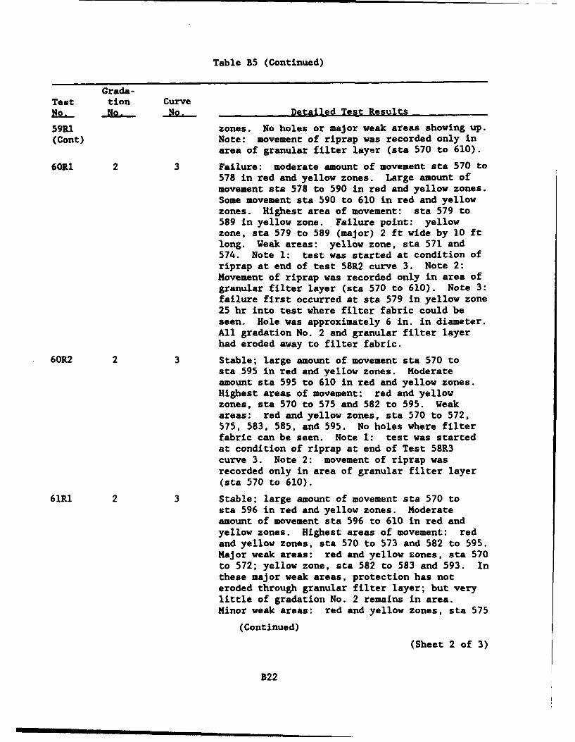
Table B5 (Continued)
Grada-Test tion Curvefig. No. No. Detailed Test Results
59R1 zones. No holes or major weak areas showing up.(Cont) Note: movement of riprap was recorded only in
area of granular filter layer (sta 570 to 610).
60R1 2 3 Failure: moderate amount of movement sta 570 to578 in red and yellow zones. Large amount ofmovement sta 578 to 590 in red and yellow zones.Some movement sta 590 to 610 in red and yellowzones. Highest area of movement: sta 579 to589 in yellow zone. Failure point: yellowzone, sta 579 to 589 (major) 2 ft wide by 10 ftlong. Weak areas: yellow zone, sta 571 and574. Note 1: test was started at condition ofriprap at end of test 58R2 curve 3. Note 2:Movement of riprap was recorded only in area ofgranular filter layer (sta 570 to 610). Note 3:failure first occurred at sta 579 in yellow zone25 hr into test where filter fabric could beseen. Hole was approximately 6 in. in diameter.All gradation No. 2 and granular filter layerhad eroded away to filter fabric.
60R2 2 3 Stable; large amount of movement sta 570 tosta 595 in red and yellow zones. Moderateamount sta 595 to 610 in red and yellow zones.Highest areas of movement: red and yellowzones, sta 570 to 575 and 582 to 595. Weakareas: red and yellow zones, sta 570 to 572,575, 583, 585, and 595. No holes where filterfabric can be seen. Note 1: test was startedat condition of riprap at end of Test 58R3curve 3. Note 2: movement of riprap wasrecorded only in area of granular filter layer(sta 570 to 610).
61R1 2 3 Stable; large amount of movement sta 570 tosta 596 in red and yellow zones. Moderateamount of movement sta 596 to 610 in red andyellow zones. Highest areas of movement: redand yellow zones, sta 570 to 573 and 582 to 595.Major weak areas: red and yellow zones, sta 570to 572; yellow zone, sta 582 to 583 and 593. Inthese major weak areas, protection has noteroded through granular filter layer; but verylittle of gradation No. 2 remains in area.Minor weak areas: red and yellow zones, sta 575
(Continued)
(Sheet 2 of 3)
B22
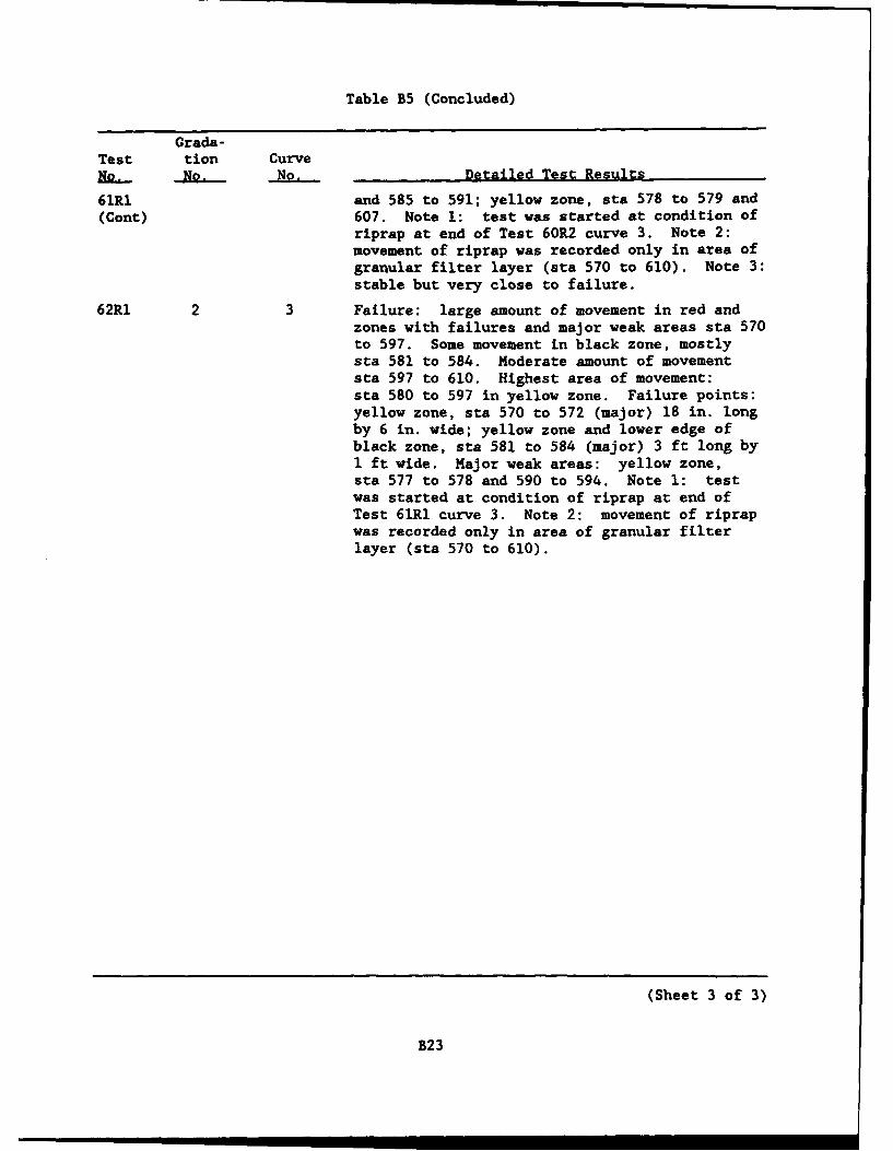
Table B5 (Concluded)
Grada-Test tion CurveNo.- No. No. Detailed Test Results
61R1 and 585 to 591; yellow zone, sta 578 to 579 and(Cont) 607. Note 1: test was started at condition of
riprap at end of Test 60R2 curve 3. Note 2:movement of riprap was recorded only in area ofgranular filter layer (sta 570 to 610). Note 3:stable but very close to failure.
62R1 2 3 Failure: large amount of movement in red andzones with failures and major weak areas sta 570to 597. Some movement in black zone, mostlysta 581 to 584. Moderate amount of movementsta 597 to 610. Highest area of movement:sta 580 to 597 in yellow zone. Failure points:yellow zone, sta 570 to 572 (major) 18 in. longby 6 in. wide; yellow zone and lower edge ofblack zone, sta 581 to 584 (major) 3 ft long by1 ft wide. Major weak areas: yellow zone,sta 577 to 578 and 590 to 594. Note 1: testwas started at condition of riprap at end ofTest 61R1 curve 3. Note 2: movement of riprapwas recorded only in area of granular filterlayer (sta 570 to 610).
(Sheet 3 of 3)
B23
APPENDIX C: NOTATION
Cl
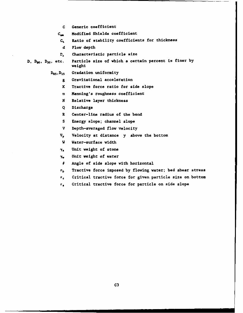
C Generic coefficient
Cm Modified Shields coefficient
Ct Ratio of stability coefficients for thickness
d Flow depth
D9 Characteristic particle size
D, D9, D30 , etc. Particle size of which a certain percent is finer byweight
D 1v, 5 Gradation uniformity
g Gravitational acceleration
K Tractive force ratio for side slope
n Manning's roughness coefficient
N Relative layer thickness
Q Discharge
R Center-line radius of the bend
S Energy slope; channel slope
V Depth-averaged flow velocity
Vy Velocity at distance y above the bottom
W Water-surface width
7, Unit weight of stone
-y. Unit weight of water
e Angle of side slope with horizontal
Tb Tractive force imposed by flowing water; bed shear stress
T Critical tractive force for given particle size on bottom
rT Critical tractive force for particle on side slope
C3
Waterways Experiment Station Cataloglng-In-Publication Data
Maynord, Stephen T.Riprap stability : studies in near-prototype size laboratory channel / by
Stephen T. Maynord ; prepared for Department of the Army, U.S. ArmyCorps of Engineers.
240 p. : ill. ; 28 cm. - (Technical report ; HL-92-5)Includes bibliographic references.1. Embankments. 2. Channels (Hydraulic engineering) 3. Hydraulic
models. 4. River channels. I. United States. Army. Corps of Engineers.II. Flood Control Structures Research Program. Ill. U.S. Army EngineerWaterways Experiment Station. IV. Title. V. Series: Technical report(U.S. Army Engineer Waterways Experiment Station) ; HL-92-5.TA7 W34 no.HL-92-5