Embed Size (px)
Citation preview
AD-AO15 461
ANALYSIS OF WEAR DATA FROM OSMM M68 GUN TUBESIN FIELD SERVICE
Allan A. Albright, et al
Watervliet Arsenal
Prepared for:
Army Armament Command
June 1975
DISTRIBUTED BY:
Nalum u TuXbi Suilce
U. S. DEPAR1TENT OF COMMERCE
Uncasified~__SECURITY CLASSICICATION Or THIS PAGE (W hI., De to f.l . REDl
REPORT DOCUMENTATION PAGE B READ CPSTRUCTIONSBEFORE COMPLETING FORM
RIEPOU�UIUN. 12 GOVT ACCESSION NO 3 RECIPIENT'S CATALOG NUMBER
rVT-TR-750 TYPE F REPORT A PERIOD COV;RED
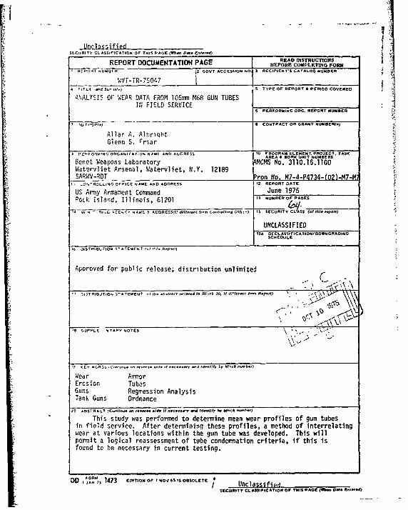
ANALYSIS OF WEAR DATA FROM 105m M68 GUN TUBESIN FIELD SERVICE
6 PERFORMING ORG. REPORT NUMBER
I IU T,'O CONTPACT OR GRANT NUMERI(*)
Allar A. AlbrightGlenn S. rriar
I PE -0o9ING ORGANuIZATION N AMC AND ADDRESS 10 PROGRAM ELEMENT. PROJECT, TASK
AREA WORK UNIT NUMB•RS
Benet Weapons Laboratory MCMS No. 3110.15.1100Wateryliet Arsenal, Watervliet, N.Y. 12189SAR.'WV-RDT Pron No. MZ-4-P4734-(02)-M7-H
I I ý'%-ROLLING OFFICE NAME AND ADDRESS 12 REPORT DATE
US Army Armament Cornrand June 1975Pock island, Illinois, 61201 ,, NUMREROFPAGES
lv4 ROi. l AC CY RNAMF- & AOGRESS01 diff.I f- Ct-1,.0I* OIhcoI IS SECURITY S (ofWe tePOf,
UNCLASSIFIED
11 OECLASSI ICATIONIOOWNGRAOINGSCHEDULE
lb OISTRIBUTION STATEMENT (0•51 0I.1iepo-I
Approved for public release; distribution unlimited
( -0
'N SUPPLE NTAPY NOTES
Wear ArmorErosion TubesGuns Regression AnalysisTank Guns Ordnance
20 ADST7RACT (C-11-.. -. --.. .Ide It I..c...l 6d. 1. 61- N -eRIN-)t
This study was performed to determine mean wear profiles of gun tubesin field service. After determining these profiles, a method of interrelatingwear at various locations within the gun tube was developed. This willpermit a logical reassessment of tube condemnation criteria, if this isfound to be necessary in current testing.
DD 1473 EOITION 0E 1 NOf 6S IS OBSOLETEJ/ Unclassifiald
SECURITY CLASSIFICATION OF THIS PAGOE (ON- VN•IR
TABLE OF CONTENTS
DD Form 1473
Introduction 1
Field Sampling Plan 3
Preliminiry Analysis of Field Measurements 5
Selection of Representative Tubes for Test Firing 15
Analysis of Data 24
Seccpdary Wear 24
Relative Land and Groove Wear 28
Effect of Tube Sample Segregations 30
Effect of Reducing Primary Land Wear Requirement 33
Conclusions 39
Recommendations 40
Appendix A: Procedur*- for Candidate Gun Tube Selection 41
Appendix B: Relating Primary & Secondary Wear Measurements 43
Appendix C: Gun Tube Sample Groupings 44
Appendix D: Impact of Changing Tube Wear Condemning Limits 52
ia
LIST OF ILLUSTRATIONS
Figure Page
1. M68 Gun Tube: Mean Land Wear with 90/90 ToleranceLimits - First Wear Quarter 7
2. M68 Gun Tube: Mean Groove Wear with 90/90 ToleranceLimits - First Wear Quarter 8
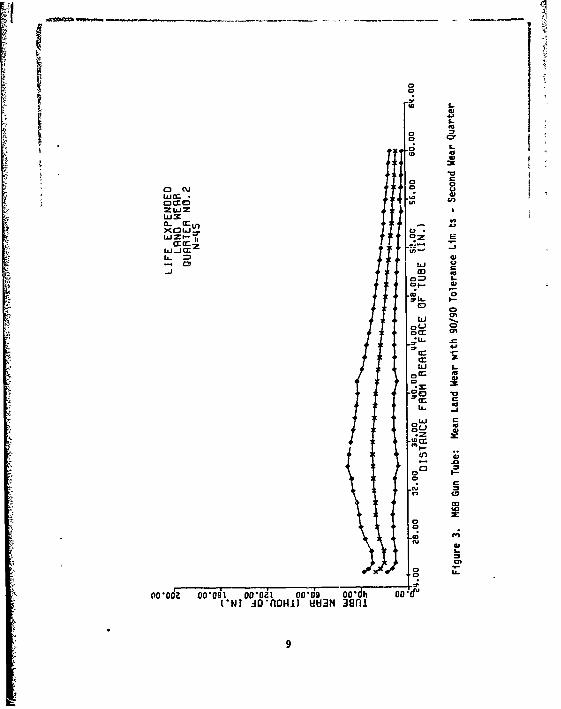
3. M68 Gun Tube: Mean Land Wear with 90/90 ToleranceLimits - Second Wear Quarter g
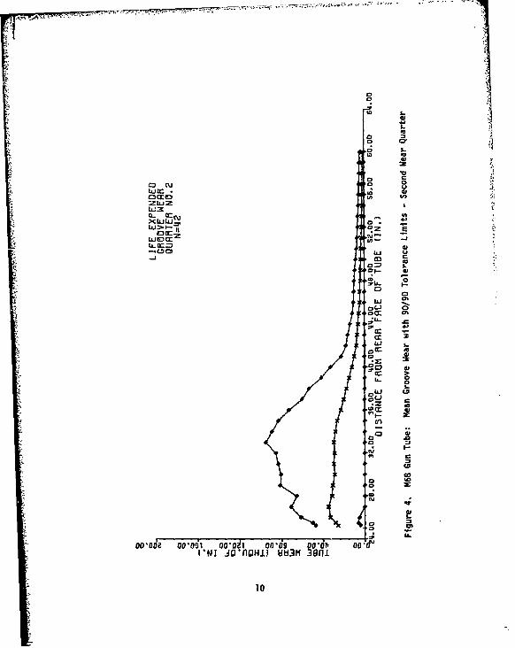
4. M68 Gun Tube: Mean Groove Wear with 90/90 ToleranceLimits - Second Wear Quarter 10
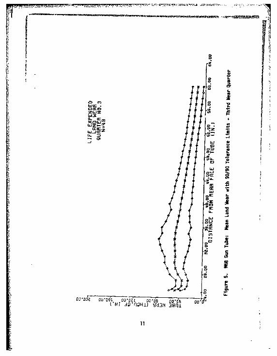
5. M68 Gun Tube: Mean Land Wear with 90/90 ToleranceLimits - Third Wear Quarter 11
6. M68 Gun Tube: Mean Groove Wear with 90/90 ToleranceLimits - Third Wear Quarter 12
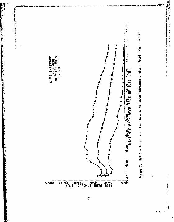
7. M6P Gun Tube: Mean Land Wear with 90/90 ToleranceLimits - Fourth Wear Quarter 13
8. M68 Gun Tube: Mean Groove Wear with 90/90 ToleranceLimits - Fourth Wear Quarter 14
9. Tube Number 7366 - Land Wear with One S.D. Limits forCorresponding Wear Quarter 16
10. Tube Number 7366 - Groove Wear with One S.D. Limits fGrCorresponding Wear Quarter 17
11. Tube Number 7500 - Land Wear with One S.D. Limits forCorresponding Wear Quarter 18
12. Tube Number 7500 - Groove Wear with One S.D. Limits forCorresponding Wear Quarter 19
13. Tube Number 7465 - Land Wear with One S.D. Limits forCorresponding Wear Quarter 20
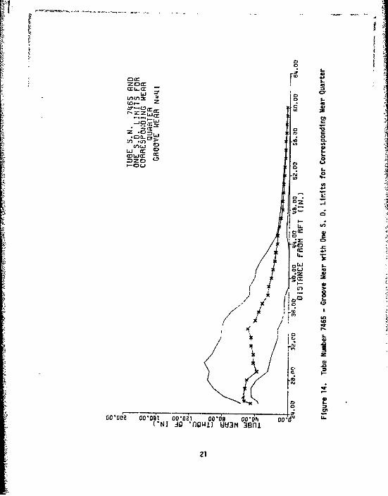
14. Tube Number 7465 - Groove Wear with One S.D. Limits forCorresponding Wear Quarter 21
ii

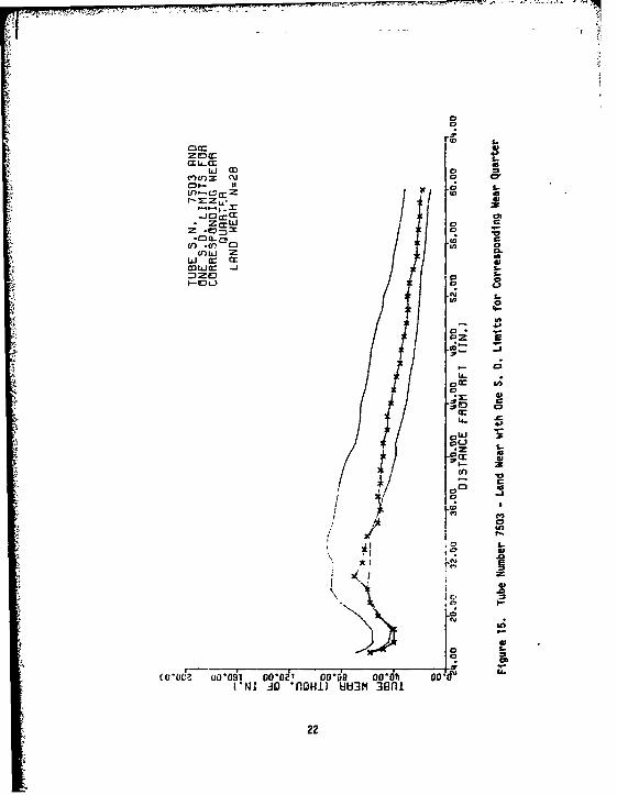
15. Tube Number 7503 - Land Wear with One S.D. Limits forCorresponding Wear Quarter 22
16. Tute Number 7503 - Groove Wear with One S.D. Limits forCorresponding Wear Quarter 23
17. Primary vs. Secondary Land Wear with Regression Line 25
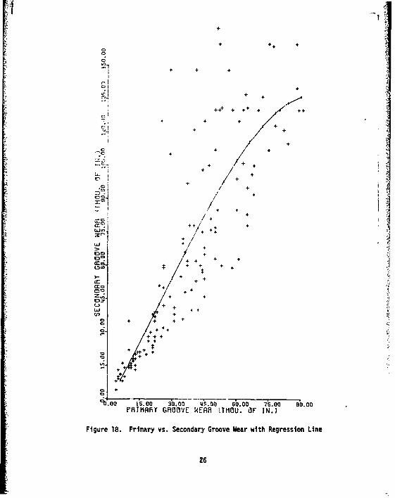
18. Primary vs. Secondary Groove Wear with Regression Line 26
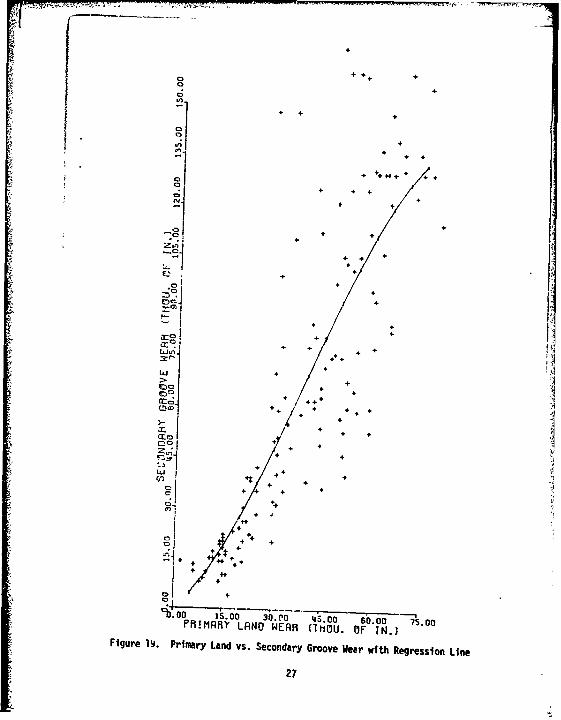
19. Primary Land vs. Secondary Groove Wear with RegressionLine 27
20. Secondary Land and Groove Wear vs. Primary Land Wear 29
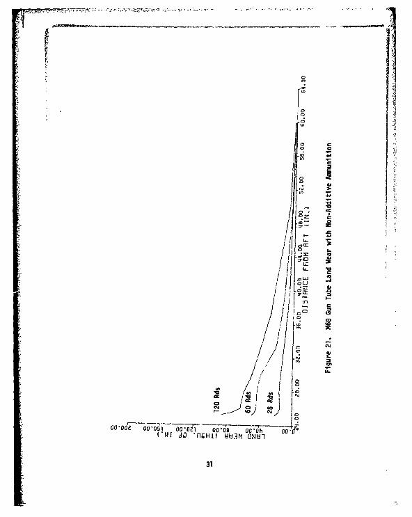
21. M68 Gun Tube Land Wear with Non-Additive Ammunition 31
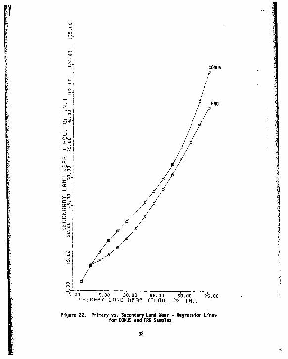
22. Primary vs. Secondary Land Wear - Regression Lines forCONUS and FRG Samples 32
23. Gun Tube Population Disposition after a 20% Reductionin Primary Land Wear 35
24. Gun Tube Population Disposition after a 20% Reductionin Primary Groove Wear 36
25. Gun Tube Population Disposition after a 20% Reductionin Primary Land Wear 37
Al. Candidate Gun Tube Selection 42
Cl. Primary vs. Secondary Land Wear - Regression Lines forCONUS Serial Number Groups 46
C2. Primary vs. Secondary Lend Wear - Regression Lines forFRG Serial Number Groups 47
C3. Primary vs. Secondary Land Wear - Regression Lines forCONUS and FRG Samples by Serial Number Group 48
C4. Primary vs. Secondary Land Wear - Regression Lines forCONUS Location Groups 49
CS. Primary vs. Secondary Land Wear - Regression Lines forFRG Location Groups 50
Iii

C6. Primary vs. Secondary Land Wear - Regression Lines forCONUS and FRG Location Groups 51
DI. Trade-off Analysis - Secondary vs. Primary Land Wear 54
D2. Trade-off Analyais - Secondary vs. Primary Groove Wear 55
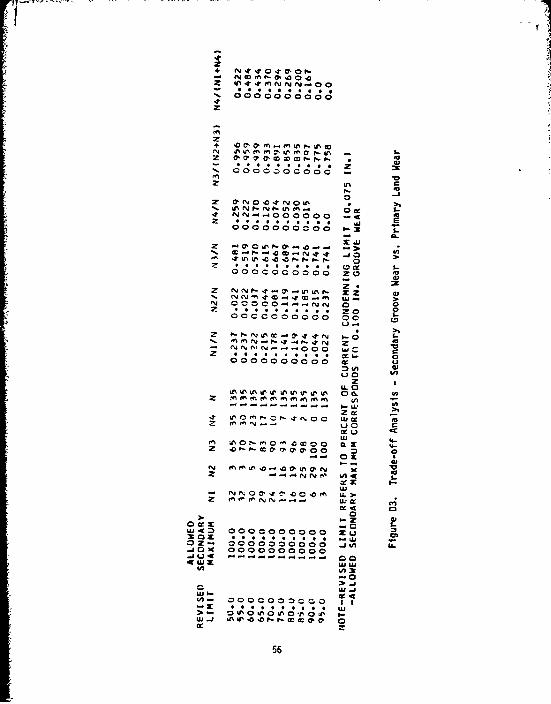
03. Trade-off Analysis - Secondary Groove Wear vs. PrimaryLand Wear 56
iv

INTRODUCTION
The Cannon, 105MM Gun:M68 has been fielded since 1960 as the primary
armament for the M60-series (F60, M6OAI, M6OAIE3) and, later versions
of, the M48-series iredium tanks. The United Kingdom fields a similar
gun (105MM Tank Gun L7) with a gin tube interchangeable with that of the
M68.
A variety of ammunition, classified according to projectile type
as APERS-T, APDS-T, HEAT-T, HEP-T, WP-T, and TP-T, is fired in the M68.
The M392-series APDS-T cartridge is of the hyper-velocity, armor-piercing
type with discarding sabot and is intended for use in defeating armored
targets. The M490 TP-T cartridge is used extensively in marksmanship
training.1
In 1964, efforts to increase the relatively short wear life of the
M68 Gun tube culminated in the adoption of several forms and
configurations of wear reducing additives included with the cartridge
propellant ci,.rge.2, 3 Reductions in bore wear rates to as little as
ITM 9-1300-203, Artillery Ammunition, DA, April, 19672APG Report No. DPS-768, Component Development Test of Laminar Coolant,Barrel-Wear Reducing Additive in Cartridge, 105MM, APDS-T, M392E!, for105M.1 Gun, M68, Ammunition Components, January, 1963.3APG Report No. DPS-83S, Component Development Test of Swedish Barrel-Wear Reducing Additive for 105MM Gun, M68, Ammunition Components,March, 1963.
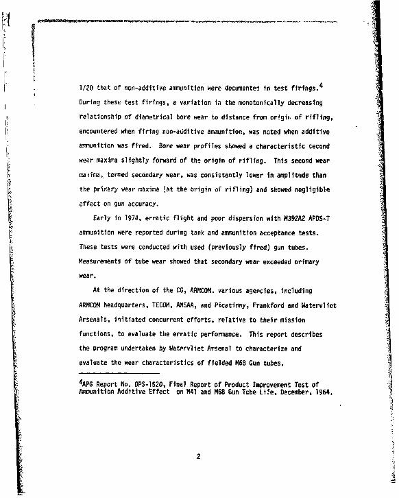
I1/20 that of non-additive ammunition were documented in test firings. 4
During these test firings, a variation in the monotonically decreasing
relationship of diametrical bore wear to distance from or~gfi, of rifling,
encountered when firing non-additive annunition, was noted when additive
anmunition was fired. Bore wear profiles showed a characteristic second
wear maxima slightly forward of the origin of rifling. This second wear
mad4r, termed secondary wear, was consistently lower in amplitude than
the primary wear maxima (at the origin of rifling) and showed negligible
effect on gun accuracy.
Early in 1974, erratic flight and poor dispersion with ?4392A2 APDS-T
ammunition were reported during tank and ammunition acceptance tests.
These tests were conducted with used (previously fired) gun tubes.
Measurements of tube wear showed that secondary wear exceeded orimary
wear.
At the direction of the CG, ARMCOM. various agencies, including
ARMCOM headquarters, TECOM, AMSAA, and Picatinny, Frankford and Watervliet
Arsenals, initiated concurrent efforts, relative to their mission
functions, to evaluate the erratic performance. This report describes
the program undertaken by Watervliet Arsenal to characterize and
evaluate the wear characteristics of fielded M68 Gun tubes.
4APG Report No. OPS-1520, Final Report of Product Improvement Test ofAmmunition Additive Effect on M41 and M68 Gun Tube Lire, December, 1964.
2
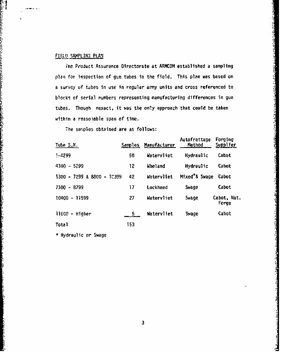
FIELD SAMPLINS PLAN
rne Product Assurance Directorate at ARMCOM established a sampling
plan for inspection of gun tubes in the field. This plan was based on
a survey of tubes in use in regular army units and cross referenced to
blocks of serial numbers representing manufacturing differences in gun
tubes. Though nexact, it was the only approach that could be taken
within a reasoiable span of time.
The sariples obtained are as follows:
Autofrettage ForgingTube S.N. Samples Manufacturer Method Supplier
1-4299 50 Watervliet Hydraulic Cabot
4300 - 5299 12 Wheland Hydraulic Cabot
5300 - 7299 & 8800 - 1C399 42 Watervliet Mixed*& Swage Cabot
7300 - 8799 17 Lockheed Swage Cabot
10400 - 11599 27 Watervliet Swage Cabot, Nat.Forge
11600 - Higher 5 Watervliet Swage Cabot
Total 153
* Hydraulic or Swage
3

The samples were obtained from the following locations:
Locations Samples
Ft. Hood 25
APG & JPG 6
Ft. Lewis 8
Ft. Knox 29
Ft. Riley 9
Ft. Carson 10
Conus/Total 87
Friedberg, Germany (I BN. 32 Armor Bde.) 9
Kirchgon, Germany (2 Bn. 32 Armor Bde.) 9
Friedberg, Germany (3 Bn. 32 Armor Bde.) 4
Mannheim, Germany (3 Bn. 68 Armor Bde.) 25
Mannheim, Germany (5 Bn. 68 Armor Bde.) 19
FRG/Total 66
Grand Total 153
4
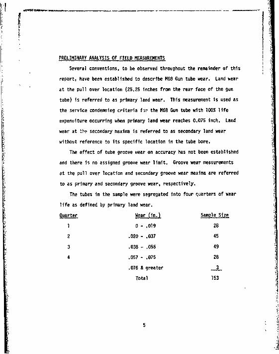
PRELIMINARY ANALYSIS OF FIELD MEASUREMENTS
Several conventions, to be observed throughout the remainder of this
report, have been established to describe M68 Gun tube wear. Land wear
at the pull over location (25.25 inches from the rear face of the gun
tube) is referred to as primary land wear. This measurement is used as
the service condemning criteria for the M68 Gun tube with 100% life
expenuiture occurring when primary land wear reaches 0.075 inch. Land
wear at the secondary maxima is referred to as secondary land wear
without reference to its specific location in the tube bore.
The effect of tube groove wear on accuracy has not been established
and there is no assigned groove wear limit. Groove wear measurements
at the pull over location and secondary groove wear maxima are referred
to as primary and secondary groove wear, respectively.
The tubes in the sample were segregated into four quarters of wear
life as defined by primary land wear.
Quarter Wear (in.) Sample Size
1 0 - .019 28
2 .020 - .037 45
3 .038 - .056 49
4 .057 - .075 28
.076 & greater 3
Total 153
5
The actual wear data was subjected to computer analysis to determine
mean wear profiles for each quarter of wear life for both land and groove
measurements (Figures 1 - 8). Also, assuming normal distribution of
data within wear quarters for each measurement distance, 90% tolerance
limits (90% confidence) were placed about the mear profiles to show the
extent of vLriation within each wear quarter. These tolerance limits
are shown on Figures 1 - 8. The tube profiles prove conclusively that
fielded tubes will exhibit secondary wear exceeding primary wear.
Measurements from early tube samples did not include groove data,
this is reflected by the smaller number of samples shown in each groove
wear quarter.
6

No
0 4
Wo= U)OCCEI -4.
ZLLJ= 0
0-
XMILI,I'-- 1)9 E
C) LLa C
9- U
01
ILJ C,
0 C%
*s cnecc
C;I
zCC_ _ _ __ _ _ _ a; 0
ooc~ oooi o.o~i srdo oivd oC!
4r
0j

S.I
ocreD
a--
woco
a)
w TZ*L a.U
)(LLJ.Lcu 0.
0aU 5
0.
En
01
oo-od2 ~ ~ ~ ~ ~ ~ .oo.~ od rd rh c dJg~nQI) UU 49n
m CU
0ý cc
0 CC
o ~CD
'ID
--
W,,a:
-J a
00-00jo*=41i UUM 9.
0 cu
mce O L
EC4-.
L
u0
*0o
0A CU.9
C3
CN. -4*rHI U8M3
)C~iJiJ 10
*!~~ ~*Olt
CL -
LL. M.
ocrD I- -
U-
o0
C0
L9;
('NT * 041) UM 39

0
Z Lo Z
foc4,
_j 3-
c,
o s
0 ~~*ccwcr . . -
'm
'.00 do
--J
C,
2( ~ CD
12 .
Ic
459D
o o
oacc
OM Z
C!tAJ -
0i
vu -
0
Ocr
-o
I.-in
0i5-
(*NI~~*5 .4r oC UJM3
13w
C) zC
30
oj XCL C=
X LO UZ~C,
wo z
0 .
ooui
CD
0~-
oc~~oc ood 0.h 0-
14 4

SELECTION OF REPRESENTATIVE TUBES FOR TEST FIRING
All tubes in each wear quarter were ranked against the respective
mean profile and a tube as representative as possible was selected and
forwarded to Aberdeen Proving Grounds for test firings conducted under
the supervision of Picatinny Arsenal. The tubes selected as most
representative are listed below; their wear profiles are shown In
Figures 9 - 16. Since no tube exactly represents the mean profile,
selected tube profiles shown in Figures 9 - 16 are bounded by lines
representing one sample standard deviation corresponding to the respective
sample mean to show the relationship to the assumed population
distribution. An explanation of the selection procedur-e is given in
Appendix A; the predominant factor in selection was groove wear.
Wear Quarter Candidate Tube
7366
2 7500
3 7465
4 7503
15
ZC)(C
Cc L. r L..Li (X)
(1- Z 1.w
.J c
* DL o * -L) .(f) C.,D
W12. z w~ 06
0.
S..
0S..
0 LI3rU3
47-
C0*G2 OCCSIN 00*21 0 ,69 0Iv*A041 .43M..n
16*
cr~..a
ow0 )
C3 0
0)
E0
00*02 00041 0.0 00-o oodh 04.f
(*Nj ~ ~ ~ g .o*QD U8M3n
17J
awca
zc j LO.)(:(r: v. L.
:lo a: Im
CLI-) = 0 0a~- C?* S.
w =Q a=Z 0 0
*~0 C0,
zzc La
(*Nl ~ ~ ~ U 0Q*o.) UM3
184

IcI0.
z EDc
Li 0 Cc:
0
110
191

0)
orc 4-
Ld a) 0 2Lfl(f)z =r 0
cop- 115
9L 0
U')0 .
0 d
oz -
I--
in i
200
4-
ZC)CC
* ~crC;
Li a)S.MLJ CC
S-
II-
,.z 0
car
0006 ,,-0 3m000 D
(*Nl~ ~ ~ -4 z111WI3n
21
-P.. 17.1-, 7-7-57- 77' " a
tj 00M'COM CU 6 c'
(0z z CL
03 aL iJ CC
Z.r *cS6 -
Z
CA .(f C an
z~ 6-~ a: I"(n
~Lj~23 Or62
CDgLO
C7 vI
cu.
9n4.&
w~ca U0.41 0-06 09- 0061, 00 -.
t*Ni ~ ~ ~ e doeoi iuM3n
22~.

rf~f
zcr Lr (r
0 z
.- 0 = L
(1'.i CC p
0ujx Ccen0DZED0
LL- ttnCD
,~ ~ *z C0
-~ s-
I-.
co-Oo~coi ~ Lc o o
23

ANALYSIS OF DATA
The available data was evaluated for several purposes using regression
analysis (See Appendix B).
Secondary Wear
First, all the data was utilized to project the relationship
between p-imary and secondary wear for both the lands and grooYes. The
results of this analysis (Figure 17) indicate that mean secondary land
wear of .075 inches occurs when primary land wear is only .061 inches.
In the case of the grooves (Figure 18), mean secondary groove wear of
.075 inches occurs when primary groove wear is oaily .041 inches. The
relationship of secondary groove wear to primary land wear is shown in
Figure 19. In this instance, mean seconaary groove wear of .075 inches
corresponds to primary land wear of .0425 inches,
If consideration is restricted to secondary land and groove wear in
the fourth wear quarter sample, as depicted in Figures 7 and 8. mean land
wear of 0.075 inch can be seen to coincide with 0.100 inch g'oove wear.
While inconclusive, it is noted that the United Kingdom condemns gun
tubes for reaching their wear accuracy limit at 0.100 inch land wear
and that the United Kingdom does not fire M490 or M456-series cartridges.
24

Os
t+
ill+ +I
0
+L- + +
+
+ + +
++CD +/
=D+ + +
+
Ecr- + /++
+ +
0 . 4+ 4+
S+ ++ + +
44+ ÷4. +
+/" +4 + +Z +÷4. +! , -i+
Cr.
+ ++
z` + +• +I
, 444I +I-L +
++4
+ +4+++ +
~00 15.00 30.00 b.00 610. 0 75.00
PRIMRRY LRNO WERR (THOU. OF IN.]
Figure 17. Primary vs. Secondary Land Wear With Regression Line
25
+ +÷
+ + +
0+
+ +
44++ + +÷ + +
Cl + +
/+. + +
+ +
.C + +
++
+ ÷ 4-+
+
++ +
/+ +
U- +; ++
/ /
+ +~+ 4 + 4
+ +tj + +
W ++
n+ + + +
++ 4
+ ++
++
++
PRIMARY GROE ER H .O I.
Fir + P
o + + 4 2
o 4
÷444÷+4
4 *4.44-- 4'~o •o0--••-• -s~o •o bo
P0 I 4+ FOVENR :TO. F I.
Fiue1.Pi4 yv.ScnayGov erwt ersinLn
- + 4
tD + ++LO
v; 4"
+
+ +of
4 - + 44 4
0+
OM
X- +
4.+ +,
& ++
-+
"'0 I
pi *,O+ - 7
HFIMAY LAND NEARj (THOU. OF IN.]Figure 19. Primary Land vs. Secondary Groove Weer with Regression Line
27
Relative Land And Groove Wear
Secondary land and groove wear has been shown to exceed corresponding
primary wear. Figure 20 shows the amount (as percent) by which the
expected values of secondary land and groove wear exceed primary land
weir, as tube wear life progresses, and depicts the predominance of
excess secondary groove wear. This predominance is further demonstrated
when it is noted that secondary groove wear exceeded prinary groove wear
in all but three of the 153 gun tubes sampled.
28

CD
a: Icc0
5j
o 2 ,. .00 4o.00 6b. 00 8b. 00 1 o.o00PR!I',IqRT LAlND WE~qR (PERWENT3
Figure 20. Secondary Land and Grooye vs. Primary Land Wear
29

Effect Of Tube Sample Segregations
The model used to project the relationship between primary and
secondary land wear has been applied to measurements segregated into
the various sample groups specified in the field sampling plan described
earlier. Severa& contributing factors must be considered in drawing
conclusions from these group comparisons.
The evolution of an M68 gun tube wear profile is governed to some
degree by tne types of armh.nition fired, especially in situations where
combinations of additive and non-additive (e.g. T382, M392, M456)
ammunition have been fired. Figure 21 shows the evolution of bore wear
in an M68 gun tube firing ammunition without bore wear reducing additive.
Gun tubes in the sample dating from production and proofing in the early
1960's were fielded with high (.007 - .012 inch) initial wear with
profiles similar to those shown in Figure 21. As indicated in Appendix
C, the majority of tubes in the FRG sample exhibit this condition.
Figure 22 shows the relationship between primary dnd secondary land
wear for the CONUS and FRG tube samples. With consideration given to
the high initial primary wear in the FRG tubes, this relationship is
effectively the same for both sample groups. Similar results are
obtained from various other sample groupings and are described in Appendix
C.
30
00
o cmo Go
311
,A
C)1
CONUS
FRG
Cz
iJ
0 .00 30.00 q5. o0 60.00 s.0ooPRIMRRY LRNO WEAR (THOU. OF IN.)
Figure 22. Primary vs. Secondary Land Wear - Regression Lines
for CONUS and FRG Samples
32
Effect Of Reducing Primary Land Wear Requirement
If it is established that it is necessary to revise or amend the
existing tube wear life criteria, it will be advantageous to predict the
impact of such a criteria on the present gun tube population. For example,
if it is found that secondary land wear in excess of 0.075 inch produces
unacceptable performance, and the condemnation criteria is to be based
on primary land wear, a reduction in the allowed primary land wear will
not only condemn tubes with excess secondary land wear, but will also
condemn tubes with acceptable (in this hypothetical situation) secondary
land wear (cf. Figure 17). In addition, unless the reduction in the
primary land wear limit is extreme, a number of tubes with excess
secondary land wear will survive under the revised criteria.
A trade-off analysis, described in Appendix D, has been conducted,
assuming the field wear survey data as representative of the total gun
tube population wear life distribution. Examples of the results of this
analysis for specific condemnation situations are shown in Figures 23 -
25.
Figure 23 shows the disposition of the current field population after
a 20% (0.075 to 0.060 inch) reduction in the primary land wear condemning
criteria. As indicated in the fiqure, 3.4% of the tubes acceptable under
the present criteria would be condemned with secondarv land wear less
than 0.075 inch and 3.4Y of the tubes accepted under the revised criteria
33
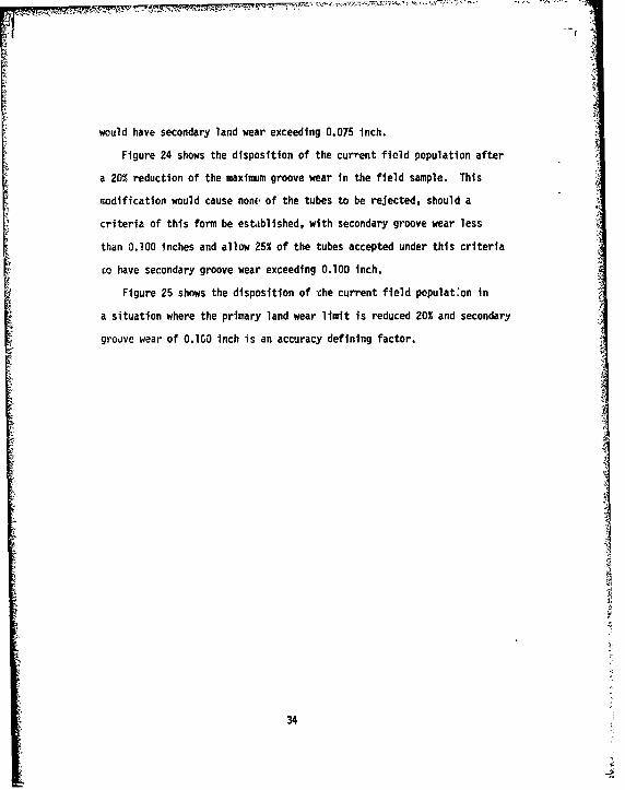
would have secondary land wear exceeding 0.075 Inch.
Figure 24 shows the disposition of the current field population after
a 20% reduction of the maximum groove wear in the field sample. This
modification would cause none of the tubes to be rejected, should a
criteria of this form be established, with secondary groove wear less
than 0.100 Inches and allow 25% of the tubes accepted under this criteria
co have secondary groove wear exceeding 0.100 inch.
Figure 25 shows the disposition of the current field populat:on in
a situation where the primary land wear limit is reduced 20% and secondary
groove wear of O.lGO inch is an accuracy defining factor.
34

II/ \ / \v
I, ,I /./ '• /
I/
\\. I /
II: 3.4% accepted w/excessive secondary land wearIII: 82.4% accepted w/o excessive secondary land wear
85.8• total accepted
I: 10.8% rejected w/excessive secondary land wearIV: 3.4% rejecteo w/o excessive secondary land wear
14.2% total rejected
Figure 23. Gun Tube Population Disposition after a 20% Reductionin Primary Land Wear
35

III /
I1: 25% accepted w/secondary groove wear greater than 0.100"
IIT: 74% accepted w/o excessive secondary groove wear99% total accepted
1: 1% rejected w/secondary groove wear greater than 0.100"(L% rejected w/o excessive secondary wear)1% total rejected
Figure 24. Gun Tube Population Disposition after a 20% Redurtionin Primary Groove Wear
36

11 4 cetdwscnaygroewa rae hn010111 714cetdwoecsiv eodr roewa
W5%totl ccete
T-5wea greitl reece
Figure accepunTued Popuatexcessivesecitondarytgrov w0ear cio
in Primary Land Wear
37

If the APDS-type projectile (M392/724/728) will not perform adequately
in current tests under some conditions of wear other than those defined
by the current condemnation criteria, a new condemnation criteria must
be established. This criteria could take many forms such as:
a. Secondary Land Wear
b. Primary Groove Wear
c. Secondary Groove Wear
d. Differential Groove Wear (i.e. primary vs. secondary groove wear)
e. Differential Land Wear
f. Differential Land to Groove Secondary Wear
g. Differential Land to Groove Primary Wear
In any of the above failure modes, a trade-off analysis would have
to be conducted to determine which type of tube condemnation criteria
is required to provide the best parformance at least cost. Fjr example,
the simplest solution might turn out to be to pull over gage the tubes
at 25.25 and 33 inch locations and condemn when the differential wetr
reaches a specified value. The trade-off analysi demonstrated above
will permit the analysis of the impact of any such revision in
condemnation criteria.
38
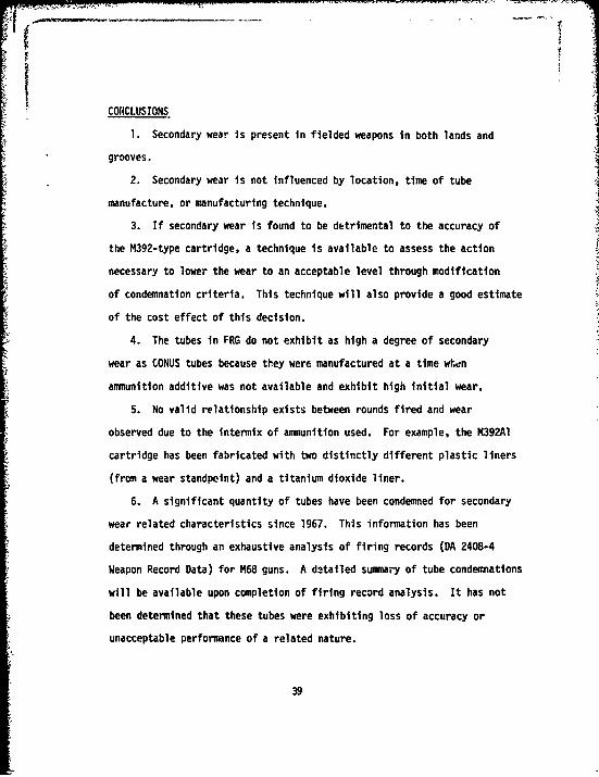
CONCLUSIONS
1. Secondary wear is present In fielded weapons in both lands and
grooves.
2. Secondary wear is not influenced by location, time of tube
manufacture, or manufacturing technique.
3. If secondary wear is found to be detrimental to the accuracy of
the M392-type cartridge, a technique is available to assess the action
necessary to lower the wear to an acceptable level through modification
of condemnation criteria. This technique will also provide a good estimate
of the cost effect of this decision.
4. The tubes in FRG do not exhibit as high a degree of secondary
wear as CONUS tubes because they were manufactured at a time when
ammunition additive was not available and exhibit high initial wear.
5. No valid relationship exists between rounds fired and wear
observed due to the intermix of ammunition used. For example, the M392A1
cartridge has been fabricated with two distinctly different plastic liners
(from a wear standpoint) and a titanium dioxide liner.
6. A significant quantity of tubes have been condemned for secondary
wear related characteristics since 1967. This information has been
determined through an exhaustive analysis of firing records (DA 2408-4
Weapon Record Data) for M68 guns. A detailed summary of tube condemnations
will be available upon completion of firing record analysis. It has not
been determined that these tubes were exhibiting loss of accuracy or
unacceptable performance of a related nature.
39

RECOIIENDATIONS
1. The ballistic test on the four selected tubes should be completed
to determine if secondary wear is the accuracy limiting factor. Should
secondary wear be found a limiting factor, then more tests must be
conducted to determine whether it is land wear, groove wear or just
differential wear that is causative.
2. If the wear limit has to be lowered, an acceptable level of
failure must be established because the variation in wear is such that
some tubes will always exceed the criteria. If an extremely low failure
level is specified, the cost could be excessive. One should also remember
that a 10' variation in field measurements would not be unusual.
3. If a new wear limit must be established it should apply only to
combat-ready equipment. Training weapons should not be condemned by
this criteria as the M490 cartildge is, and will continue for many years
to be, the main training round. This round performs adequately with the
current condemnation criteria.
4. Completion of the computer analysis of M68 firing records will
provide information necessary to assess the characteristics of the total
fielded population of M68 Gun tubes and establish a critical summary of
gun tube life histories during the past ten to fifteen years. For
example, preliminary results indicate that approximately 40% of all
tubes condemned did not reach the wear limit of 0.075 inch, being
condemned under criteria other than that imposed by the specified wear
limit. 5
51T 9-1000-202-35, Evaluation of Cannon Tubes, DA, November, 1969.
40

APPENDIX A
PROCEDURE FOR CANDIDATE GUN TUBE SELECTION
The purpose of this procedure was to establish a method ot selecting
105MM M68 gun tubes representative of the fielded population. The
specific requirement was for selection of one gun tube from each quarter
of tube wear life for use in accuracy firing tests,
Wear measurements from a total of 153 gun tubes were segregated into
samples representing the four quarters of wear life as defined by the
land wear measurement at the pull over location (25.25" from the rear
face of tube) and a wear limit of 0.075". The mean values for land
wear and for groove wear in each quarter were calculated and the sum of
squares of the deviations from the calculated mean measurements for each
member gun tube computed. Candidate gun tube ranking was established
by the total of summed land and groove wear mean square deviations.
Figure Al shows the results of this procedure for the sample of gun
tubes in the fourth wear quarter. Groove wear measurements were not
taken for Tubes Serial Number 8337 and 10483. As mentioned in the text,
final candidate selection was restricted by gun tube availability and
additional wear resulting from tube firing after measurements were taken.
Figures 15 and 16 depict the actual measurements for Tube Serial
Number 7503, selected as the fourth wear quarter candidate, and one
sample standard deviation limits computed under the assumption of a
normal distribution of wear measurements within the sample region.
41

QUARTILE NO. 4 ISAMPLE SIIL-28)
T"UP- SUM iOF S.F. SUM OF S.E. TITAL S.E.S.N. FOR LANDS F0R -1RGOVFS --
10,115 725 4334 5059
115L8 416 5166 56627•t3 ,569 3154 572334t,1 1608 5112 6720
2232 160--- -- 44r9 . ... 7-9.4--3745 2007 5792 7799
19,6 564 7557 81216211 1120 7061 81813473 1620 7984 96045424 999 8707 9706
3749 -3539 --6309 ---3,146 5315 4q63 1017R6Z1I I 150() 144 1065234.3 1217 9513 10785
54,j3 3729 10893 14622
46'4 148'4 15685 171746301 3 31 1469A 1-079 -56A2 7759 10373 IR1321414 13463 18427 1977540f5 4404 18379 22783
9848 220A3 20826 230341957 1030 25707 267379716 44534 -- 22744- - -4--127&5301 5501 32253 377545772 27095 70743 97R38
97c,1 42497 6081 1033788337 29610
104e3 36829
STANDARD ERRORS HAVF BEFN CALCULATEDrOR THE MEASUREMENTS FROM 25.25 TO6C.LO INCHES FROM RFT.
THE SUM OF THE STAmnARD LAnI FRRORSFOR TUBE NO. 11508 IS TIlE LEASTFOR THE 28 TUBES IN (HIS GROUP.
THE SUM OF THE STAIDARD GROOVE ERR(IRSFOR [UBE NO. 7503 IS TIlE LEASTFOR THE 26 TUBES IN THIS GROUPFOR WHICH G"P0JVF• NA4U4E9EbjT.. S WN-8TAK'-4 .
Figure Al. Candidate Gun Tube Selection
42
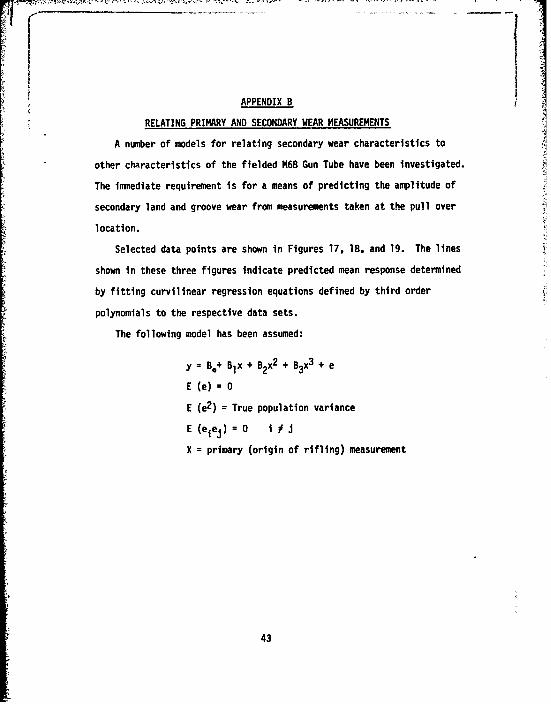
APPENDIX B
RELATING PRIMARY AND SECONDARY WEAR MEASUREMENTS
A number of models for relating secondary wear characteristics to
other characteristics of the fielded M68 Gun Tube have been investigated.
The immediate requirement is for a means of predicting the amplitude of
secondary land and groove wear from measurements taken at the pull over
location.
Selected data points are shown in Figures 17, 18. and 19. The lines
shown in these three figures indicate predicted mean response determined
by fitting curvilinear regression equations defined by third order
polynomials to the respective data sets.
The following model has been assumed:
y = B,+ Blx + B2x2 + B3x3 + e
E (e) = 0
E (e2 ) = True population variance
E (eiej) = 0 1 i
X = primary (origin of rifling) measurement
43
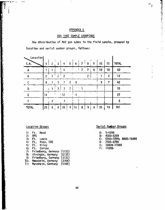
APPENDIX C
GUN TUBE SAMPLE GROUPINGS
The distribution of M68 gun tubes in the field sample, grouped by
location and serial number groups, follows:
LLocation"1 3 4 5 6 7 8 9 10 11 TOTAL
A 11 ii 7 7 4 1910 50
8 2 1 212 21 2 12
C 8 1 3,7 2 2 9 7 42
D 1j 3 3 7 1 1 15
E 14 12 1 27
F 2 3 5
TOTAL 251 6 81281 9110 1 8 151
Location Groups Serial Number Groups
1: Ft. Hood A: 1-42992: APG B: 4300-52993: Ft. Lewis C: 5300-7299; 8800-103994: Ft, Knox, CDE D: 7300-87995: Ft. Riley E: 10400-115996: Ft. Carson F: 11600-7: Friedberg, Germany (1/32)8: Kirchgon, Germany (2/32)9: Friedberg, Germany (3/32)
10: Mannheim, Germany (3/68)11: Mannheim, Germany (5/68)
44
7Figures Cl through C6 depict expected values of seconda-y wear,
calculated under the model described in Appendix B, for the following
FRdata groups:
CCONUS Serial Numbers
S ~FRG Serial Numbers
SCombined CONUS/FRG Serial Numbers
CONUS Locations
FRG Locations
Combined CONUS and FRG Locations
These comparative analyses are limited by the sample size for given
groups and the region defined by available wear measurements within each
group. As an example, the four CONUS Serial Number Groups represented
in Figure Cl allow 3, 26, 10 and 23 degrees of freedom, respectively,
for error estimation and span primary wear ranges indicated by the ranges
of points shown in the figure. When these considerations are included
with the condition of high initial wear in low serial number tubes
described in the text, the variously grouped analyses can be taken to
indicate a uniform tendency.
45

II
C
U'
2
1:40 - 529
Si 4 / I //
2: 5300 - 7299
• •,I3 "+ 7300 - 8799-,I / /4: 10400 -11599
CIl
PRI~qriy LCMD WERR (THOU. OF IN.)
Figure Cl. Primary vs. Secondary Land Wear - Regression Linesfor CONUS Serial Number Groups
46
*2
0m2
C' //- A'
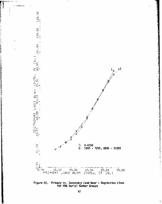
•'_ ' 2: 5300 - 7299, 8800- 10399
-J.?O0 iS.00 30.00 L.00 60.30 7S.00P;:1iM49• ýNO wIq tTHOU. JF I N.
Figure C2. Primary vs. Secondary Land Wear - Regression Lines
for FRG Serial Number Groups
47

3
SC
r /
2: 430 159
-2; // '
3: 5
(0 7
4: 7300 - 87995:10400 - 11599
. Jo s.0 0 3.0•0 S.0 00 6.6 0 75.0 0P9IMRRT LRND WEHR (THOU. OF IIN.j
Figure C3. Primary vs. Secondary Land Wear - Regression Lines
for CONUS and FRG Samples by Serial Number Group
48

I£1 I
- 4
3 /cz.J
6
weni i It Ft. ifood
i/ /• 2: Aberdeen Proving Ground,3: Ft. Lews
•.j ,/_ ,//4: Ft. Knox; CDE"z- -- I 5'7 15 Ft. Riood
for :rONUS Location Groups
49

a
a
CD
C4~4
CD
3: 33 On 8Oe
a •.
b 7
ce,-, / :/ 2 Be
oi/
P", I q9r RNhO W-EW9 iT HOU. OF I N.}
Figure CS. Primar vs. Secondary Land Near - Regrssion Linesfor FRG Location Groups
%I/

oII
-i
-i /+
C - ,//--'
' I/I/
0j /r r 3 :3 I-. , , 00 75 0
Fa['-lq~l" -•l,'J AF ~ / /TCJ i I .
Figre 6 rmr s eodr Ln er-Rgeso efo Iii n • oatnGop
z5

APPENDIX D
IMPACT OF CHANGING TUBE WEAR CONDEMNING LIMITS
This procedure is designed to reflect the impact of revising the
wear condemning limit for the M68 Gun Tube. The results indicate the
characteristics of the fielded gun tube population after assignment of
a revised criteria.
Wear measurements from the gun tube sample described in the text
are indicated by tub marks on Figures 17, e8 and 19. Assuming that
the fielded gun tube population is represented by this sample, response
to condemnation criteria revision can be calculated as ratio response.
By assign4ng acceptable values of primary wear (X) and secondary wear
(Y), four regions are established in Figures 17, 18 and 19. If X.
represents the existing wear limit with x and y representing actual
measurements, then defining:
y > Y, X < x < Xo as Region I
y > Y, O < x < X as Region II
O <y <Y, O <x <X as Region III
0 <y <Y, X < x < X. as Region IV,
gun tubes in the four regions are as follows:
Region I: unacceptable under revised criteria (X,Y),
acceptable at the existing wear limit (X.),
and unacceptable at the assigned level of secondary
wear (Y).
52
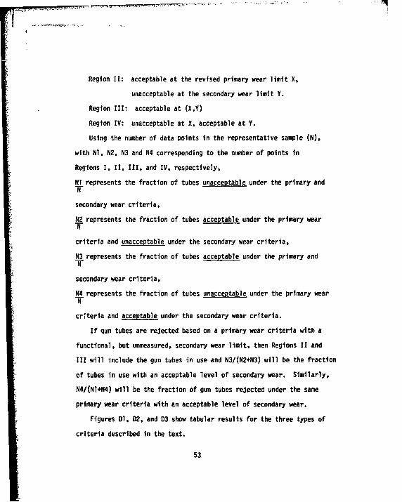
Region II: acceptable at the revised primary wear limit X,
unacceptable at the secondary wear limit Y.
Region III: acceptable at (X,Y)
Region IV: unacceptable at X, acceptable at Y.
Using the number of data points in the representative sample (N),
with NI, N2, N3 and N4 corresponding to the number of points in
Regions I, II, III, and IV, respectively,
Nl represents the fraction of tubes unacceptable under the primary andN
secondary wear criteria,
N2 represents the fraction of tubes acceptable under the primary wearT
criteria and unacceptable under the secondary wear criteria,
N3 represents the fraction of tubes acceptable under the primary andN
secondary wear criteria,
N4 represents the fraction of tubes unacceptable under the primary wearN
criteria and acceptable under the secondary wear criteria.
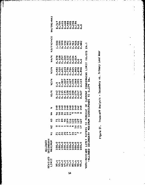
If qun tubes are rejected based on a primary wear criteria with a
functional, but unmeasured, secondary wear limit, then Regions II and
III will include the gun tubes in use and N3/(N2+N3) will be the fraction
of tubes in use with an acceptable level of secondary wear. Similarly,
N4/(Nl+N4) will be the fraction of gun tubes rejected under the same
primary wear criteria with an acceptable level of secondary wear.
Figures Dl, 02, and D3 show tabular results for the three types of
criteria described in the text.
53
2 ~O4E~lJ00
.- 00000p0
PN 00OWN0N M 0 0
200 0~OO
00.-00000000
enn
00800000000 Iol -1
en UN In M UD
N 00 W P. 'n x .
z- 00-~~1- & 4 .21.
000000000. or.00 0
.JX0000000000 ~I; 00
> ~ ~ ~ ~ L 0 N0w0in000U
w ~~~~~ ~ I- UNzJ f -ww l
541

. 000000000
-0 0
oooooooooo z- -
M~~~ ~~ LNt 1.uN i
2 . .. *Luu00%0 0 6M4nu I o5 v l O
Z 2n 22 nn : ý n 1 10£2
2r -JonocooNN N 009
N~~~ ~ ~ Ajv A4ý
- ~ u 000000 >. U!xi-c s
3CU* L %U~ 00.
0z ;
> j
Z O ol000000000C 0 '
55 0
'rw02 c.0P
uN N f
0 -J
4 NN00000o zo M
2 .v r. rj 2 a
ey~ OCaO--
z .; c; . 1...
cc o
z
OOCCO0000 00
4 4.
I- P- e - 2 0
- 0
uc
=0 *
2jo ooco~oooo 0
0
. 0>0
2
56 U