Embed Size (px)
Citation preview

UNCLASSIFIED
AD275 0 55
ARMED SERVICES TECHNICAL INFORMATION AGENCYARLINGTON HALL STATIONARLINGTON 12, VIRGINIA
UNCLASSIFIED

ACESD T -< - 62
Table of Contents
Abstract.................................................... i
Introduction ................................................. I
The Drag Formula ............................................ 2
AinendessI.............................................. .9
Wienes Ratio....................... ................ ........ 67
Wpeits .................................................... 79
Appendix 11.................... .............................. 12 IList of Symbols ............................................... 18References .................................................. 19 4
Distribution List ............... .............................. 20
List of Figures
Figure 1, Blunted Cone-Sphere Configuration ................... 14
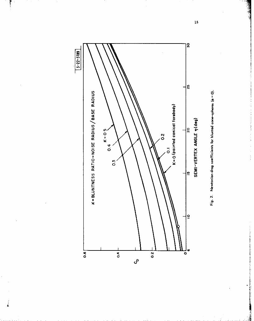
Figure 2, Graphs Of CD vs 17.............................. 15
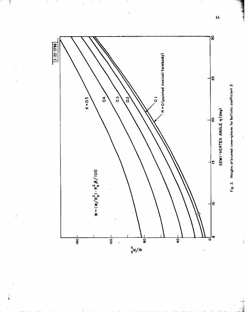
Figure 3, Graphs of W/Rb 2 vs 17............................... 16
Figure 4, Graphs of Fineness Ratio vs ................. 17
~'1Rrl::A
,1AI
N -

vi
ABSTRACT
A simple formula for the Newtonian drag coefficient is derived
for the blunted cone-sphere ("ice-cream cone") at small angles of attack. Graphs
are presented for CD as a function of cone semi-vertex angle from 60 to 300 and
"bluntness ratio" (nose-radius/base-radius) ranging in tenths from 0 to 0. 5. For
given values of the body parameters, the weight required for the body to attain a
prescribed ballistic coefficient is then determined. Fineness ratios for different
specified cone-angles and degrees of bluntness are provided for reference.
ii

Introduction. Newtonian impact theory makes two basic assumptions:
first, that the shock wave lies along the body-surface; second, that in striking the
body, the airstream loses the component of momentum normal to the surface - - the
flow is regarded as continuing along the surface with the tangential component of
momentum unchanged.
The local pressure coefficient obtained under the Newtonian hypothesis
therefore depends only on the local inclination of the surface to the airstream:
Vn 2Cp =2 va"
where v* and vn are the free-stream velocity and its component normal to the body-
surface respectively. C is taken to be zero over those portions of the surface
shielded from the flow.
The second of the basic assumptions made above neglects centrifugal
forces associated with curvature of the body surface, and the condition of the first
assumption is attained only in the limit as M -*,-y-O. (ML is the free-stream
Mach number and y the ratio of specific heats. ) In this connection, the relevant
parameter appears not to be the Mach number itself so much as the ratio M./F,
where F is the body fineness ratio
F Total body-length/Maximum body-diameter.
* See Appendix I.
i

2
For values of Me/F less than 2 for example, Newtonian estimates of the local
pressure coefficient for cones have been found 2 to be in error by more than 17%. On
the other hand, Newtonian theory has been found to give qualitative and even quanti-
tative information of acceptable accuracy in practical cases of interest at hypersonic
speeds, and the following computations of drag coefficients and related quantities
should prove useful even at high altitudes when the contributions of viscous effects *
and ablation are incorporated.
The following sections are concerned with a single configuration at
small angles of attack. The body studied consists of a cone-frustum capped at both
ends by tangent spherical surfaces. Cone semi-vertex angles between 60 and 300 are
considered with bluntness ratios (nose-radius/base-radius) ranging in tenths from
0 to 0. 5. Under the assumption of negligible pitching and zero angle of attack, a
simple formula is derived for the corresponding Newtonian drag coefficients. This
was programmed for the IBM 7090, and the tabulated values of CD so generated have
been presented in graphical form. Also presented are estimates (based on CD) of the
weight required for the body to have a prescribed ballistic coefficient. Fineness ratios
are given for reference.
The Drag Formula. The blunted cone-sphere configuration to be
considered has rotational symmetry. A coordinate system will be chosen with origin
at the nose and x measured along the axis of symmetry. (See Figure 1. ) With the
surface then described by the radial distance R = R (x), the axial -force coefficient
CX may be found by integration over the surface actually exposed to the flow:
* These are relatively important for sharp-nosed bodies during early re-entry.
A ~"I"

3
CX = si- Cps dSOI
where A is the reference-area and 0 = arctan R'(x). *
If the angle of attack is small, so that the entire surface between the
planes x = 0 and x = t, is that exposed to the flow, and if furthermore the angular
pitch-rate q is negligible in comparison with the velocity v', then integration and
simplification ** lead to an approximate expression for the drag coefficient.
CD = CX 4 R(x) R'(x)3 dx (0)C DEi = Co 1 + R '(x) 2
where the interval [o, t, I is to be broken into three segments corresponding to the
different definitions of R over the nose, midsection, and base of the body.
A spherical tip of radius Rn is generated by revolving a segment of the
circle [x - Rn] 2 + RR(x) 2 = 2; the radial distance for the nose portion of the
body is therefore
R = 2Rn x -x 2 ] 1/2 for 0-xx 1 , (i)
• See Appendix I.
** See Appendix I.
iI

4
where tangency occurs at x1. We denote by i? the (constant) semi-vertex angle of the
conical midsection, and note that
x, = Rn -R n sint7
The radial distance for the midsection is them simply
R = [x+xl/sin 7] tan / forx, _5xx 2 , (2)
where the spherical back, having radius Rb. is tangent at
x 2 = t - Rb sin 77.
Finally, the portion of the spherical back which is not shielded from the airstream has
radial distance
R = [R 2 - (x - t' )211/ 2 forx 2 _-x _:, (3)
where the maximum radius of the body is Rb = R(t. )
Computation of CD as represented by equation (0) thus requires the
integration of three separate expressions,R being defined in the respective intervals
as noted above:
5
(Rnx)3 /Rn2 for 0 s x : x,
RR' 3 RR' sin2 7 forx <xxx 2, (4)
(t. - X) 3/Rb2 for x2 !5 x -<II
b2
The second expression is easily handled with R as independent variable going between
Rn cos tj and Rb cos ij, and the other two integrations are routine.
We shall find it convenient now to take as reference-area the maximum
cross-section of the body,
A =lRb .
Substitution and integration of (4) in equation (0) then yields
CD = 2 (l - si 4 )+2( - K2 ) sin2 7cO +sin4 (5)
where we have introduced the "bluntness ratio" K = Rn/Rb as a convenient parameter.
A trigonometric identity now gives a simple formula for CD as a function of K and 77:
CD = K cos 4 17+ [ 2 - sin2 17] sin2 7. (6)
The same technique demonstrated above has been used to find CD for
the case of a blunted cone which has a flat back at distance x = L from the nose. The
corresponding formula (obtained on replacing x2 by L in equation (4)) is offered for
comparison:
CD =K 2 cos 4 + 2 sin2 1 (flat back).tD

6
The obvious similarity of the two expression conforms to the expected similarity of
body-shape when t7 is small. It should be noted that the formula we have derived for
the cone with spherical back differs from the flat-back case not only in the presence
of a (sin4 7)-term whose contribution may be negligibly small if K/i is large; but
also, for a given nose-radius, base-radius, and exposed body-length t, the spherical
back gives a larger semi-cone angle 17 than does the flat back.
A final simplification of equation (6) gives a concise formula for the
Newtonian drag coefficient of a blunted cone-sphere at small angles of attack:
CD = I- [I - K2 ] cos 4 7
where ic = Rn/RbandA = 1Rb2 .
Fineness Ratio It is easy to verify that the semi-vertex angle 17 in a
blunted cone-sphere satisfies the relation
sin 77 = (Rb- Rn )/(t. - R ).
If the total body length is denoted by L, then t. = L - Rb, and we may use the fact
that the fineness ratio is F = L/ 2Rb to write instead
sin 1- (1 - K)/(2F - [ +l),
determining the angle t7 when the ratios of Rn , Rb, and L are known. The relation
between q and F expressed by this equation is presented graphically for different
values of the bluntness ratio K in Figure 4.
4 -
7
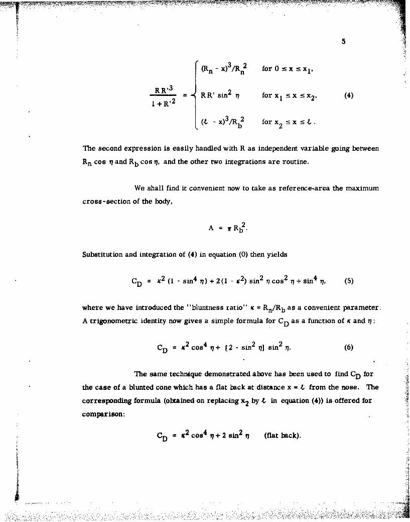
It may be of interest for comparison to note that the semi-vertex angle
1' for a flat-backed cone satisfies the relation
sin n' = (Rb cOs 7' - Rn)/(L - Rn),
where for this case t = L: It follows that if a cone with spherical back were to have
the same bluntness and fineness ratios, it would have to have a (larger) semi-vertex
angle 77, determined by the ratio
sin - I-s in w7 (cos n'- sin n7' K
Weights. While nearly constant over considerable altitude ranges in
the case of blunt-nosed bodies, the ballistic coefficient (or "weight-to-drag" ratio)
W/CDA may vary appreciably at high altitudes for sharp-nosed bodies. Viscous drag
is relatively insignificant at 50, 000 feet however, and common usage seems to base
W/CDA on the (pressure) drag at this altitude when no further qualification is mention-
ed. Since maximum deceleration of a high performance re-entry body might be ex-
pected to occur at an even lower altitude (determined by the ballistic coefficient and
the re-entry path angle), the Newtonian value of CD may therefore prove useful in
estimating the weight required for a specified ballistic coefficient to be attained.
If the desired ballistic coefficient is f, then substituting for the
reference-area A gives
W/Rb= WCDUo
!' :<i

8
The accompanying graphs of W/R2 vs 1 for different values of K are based for
W/b
scaling convenience on a ballistic coefficient of 100 lbs/ft2 . Hence, for a given semi-
vertex angle 7 (degrees bluntness ratio c, and base-radius Rb(ft), the weight W (lbs)
necessary for a ballistic coefficient p (lbs/ft2 ) is given by
W = [W/Rb 2 ].Rb2 . _'0
b 100
where the expression in brackets is the value read off from the appropriate curve.
A

9
APPENDIX I
The component of free-stream velocity V, which is in the direction
of a normal 11 to the surface-element dS has magnitude
11vn = v cos .4
n 00 VO0
so the mass striking dS normally in unit time is the product of the volume generated
and the free-stream density p,:
dm = po (vn dS).
The rate of change of momentum of the mass striking dS in the direction of the
normal gives the local pressure-force
dF = (p- P..) dS = vndm = p. v2dS
n =p 0 nd
where p and p.. are the local pressure and the free-stream pressure respectively.
As a function of the local pressure difference (p - p..) and the free-
stream dynamic pressure
q . 2% = 7P 0 v.
the local pressure coefficient
vn 2 2:v
Uv
Cj
10
thus depends only on the local inclination of the surface to the airstream. (The
flow is considered to be completely separated with C= 0 over those portions of thepj
surface shielded from the flow.)
We are concerned with a smooth body having axial symmetry. Its
surface, accordingly, may be described by giving the radial distance R as a differ-
entiable function of just the distance x measured from the nose of the body (as origin)
along the axis of symmetry The local inclination of the surface with respect to
this axis is then
0 = 0 (x) = arctanR'(x)
When there is an angle of attack a, the local pressure coefficient
varies not only with x but also with the angle w measured in a plane orthogonal to
the axis. (See Figure L ) Cp is thus dependent on a, 0, and w.
The above relations being understood, the force acting on an area -
element dS may be expressed simply as
dF = q. C p dS
The component of this force in the direction of the axis is then (sin 0)dF, and
integrating over the portion of the surface actually exposed to the airstream gives
the total axial force
F = qSCp sin 8 dS. 4
* See Appendix II.
AA

The non-dimensional axial-force coefficient Cx , defined with respect to the
reference-area A by the relation
FX =q(CxA),
may therefore be represented in the following form:
CX = " C sin 0 dS.X A p
Expressing the element of area d S by (R dw) (dx/cosO) and substituting formally
then gives
cx=+S(SC, RR'dw wdx
with integration limits corresponding to the surface exposed to the flow.
A:

12
APPENDIX II
The longitudinal axis of symmetry of the body, directed positively
back from the nose, has been chosen as the X-axis of the body coordinate system.
The free-stream velocity vector is assumed to be at a small angle of attack a (of
no greater magnitude than 17) relative to the X-axis, determining with it a plane in
which pitching occurs about the center of gravity Xcg at an angular rate q.
With these conventions, the local normal component of velocity
vn may be expressed I ' 3 in the form
vn =v, cos c [sin 0 -tan asinwcos 0 ]qsinw [(x -xcg)cos 0+RsinO],
or equivalently, upon substituting for cos 0 and tan 0,
Vn(x, W) v 00COS a R' - sin w q c [RR',+x_-xg + tan ceI
nl+R' 2 VO COS ag
It then follows from definition of Cp that
Cp (x, a, W) = 2cos 2 (R' -Gsinw) 2
I +R ' 2
where
G(x) = q [RR'+x-xcg] +tana.
VG0 Cosa

13
The entire surface corresponding to 0 _ x _5 t, and 0 w 5: 2w is
exposed to the flow at small angles of attack (a < 71), so the surface integral defining
CX may be evaluated as an iterated integral with these limits on x and W. Taking
advantage of symmetry, we obtain
t "f + /2
Cx o -/ 2 R (x) R' (x) Cp (xa, )dwdx.
It remiains to substitute for C in the form obtained above:
/2 (R- - Gsin w)2 dw = (2R ' 2 +G 2)
,. Cx = os x c a+ 2 -$o 2 (Gcos a) dx.LA I+R,2 0 1+R
The drag-force is directly opposed to the body's velocity-vector (relative to the flow)
at an angle a from the axis, and the integrand on the right is clearly bounded with q,2Hence the relation cos a - 1 for small a and the assumption that (q/v,,) is negli-
gible leaves just the bracketted expression asserted in equation (0)_
i!

"-~'14
TT
CI
0
15
0
00
ww
4 S 004 0
16
-0
0
.00
V
0ou
0 -0
w 10- 4j
CD 9
CS~~ 0 00000
L CM
z 4)0~
00
QX CA~it i
0 0 0000 N4O
q N/

17 '.0
0
00
0.
0 .
0, zOD >
0
0 V~ U-00
0 Y
E- 0 00 U0
C 0C0
tL
V 0m
Ot±VNd SS3N3NI.J
18
List of Symbols
a angle of attack (from body axis to relative-velocity vector)x, R, w cylindrical coordinates, x along axis of symmetry
R (x) body-radius in (R, w) - plane
R' (x) rate of change of body-radius along axis of symmetry
Xcg body center of gravity (distance from nose)
Rn , Rb nose-radius, base-radius of body
K "bluntness ratio", Kc = Rn/Rb
total length exposed to flow, "wetted" length
L total length of body
F fineness ratio, F = L/ 2Rb
77 semi-vertex angle for conical midsection
0 local inclination of body surface, 0 = arctan R' (x)
q angular pitch-rate about transverse axis through Xcg
p, C local pressure, local pressure coefficient
P 1, free-stream pressure, free-stream density
vo M 0 free-stream velocity, free stream Mach number1 2
q. dynamic pressure, q = o, v.,
v ncomponent of free-stream velocity normal to body surface
A reference-area for non-dimensional coefficients
C axial-force coefficient, CX = axial force/q. A
CD drag-force coefficient, CD = drag foice/q. A
5'i

19
References
1. Tolbk, M. and Wehrend, W. R.: Stability Derivatives of Cones at
Supersonic Speeds, NASA Technical Note 3788 (1956).
2. Ehret, D. M. : Accuracy of Approximate Methods for Predicting Pressures
on Pointed Non-lifting Bodies of Revolution in Supersonic Flow, NASA
Technical Note 2764 (1952).
3 Margolis, K. : Theoretical Evaluation of the Pressures, Forces and
Moments at Hypersonic Speeds Acting on Arbitrary Bodies of Revolution
Undergoing Separate and Combined Angle-of-Attack and Pitching Motions,
NASA Technical Note D652 (1961).
4. Grimminger, G., Williams, E. P., and Young, G, B W, : Lift on
Inclined Bodies of Revolution in Hypersonic Flow, Journal of the
Aeronautical Sciences, Vol. 17, No. 11 (November 1950), pp. 675- 690.

20
Distribution List
Director's Office Group 22 (cont'd ) Group 22 (cont'd.)
D, E Dustin L. F. Cianciolo C, -W UskavitchD . F Clapp T L. Vernon
Division I E. L Eaton J B. WilliamsP L. Falb J. M. Winett
R.- E . Rader A Freed P E WoodL A Gardner
Division 2 L.- A Globus PA File - J LankgjenA Gromet stein
C R. Wieser H J. Hagler Group 24
S H Dodd J H Halberstein YotR C Holland ~ ot
Division 3 J M Hoist Gop2C Hopkins Gop2
J V Harrington L KleinrockHShraA KnollHShra
Division 4 E Korngold M EnMcakiL Kraft'MSMcai
J Freedman H J. Kushner Gop2J W Meyer W Z Lemnios Gop2
D IL Lovenvirth insoDivision 7 A D MacGillivray F H KiNston
M M Marill FLM~mrD D Jacobus L M Mcixsell Gop2
L Murray Gop2Group 21 B NanniAAro
C E Nielsen AAro0 V Fortier R C NorrisP. J Harris J H Pannell Group 32
E WV PikeGroup 22 D. Reiner P B Sebring
J RheinsteinV. A Nedzel D J Sakrison Group 312J F Noran J Salerno G F, PippertW 1. Wells B. J.- Sc ha fer
D Schneider S- EdelbergA Armenti M Schneider K rsM Athanassiades F C Schweppe Group 41T. Bartee A. F. SmithR, Bergemann J S Strano A A. GalvinN. Brigham H Sussman J, B Resnick

Distribution List, (continued
Gr'p42
W. W WardP A NorthropC B SladeF BettsJB. CooperJB Jelatis
B H LabittV C MartinsW R RenhU ItR G SandholrnA F StandingC M SterninetzR C Yost
Group 43
J G Barry
Group 46
C )V Jones
Gr~oup 47
D L Clark
Group 43
R C &itrman
Group 71
F G. DeSantisP Albeiti
Group 744
J, F Hutzenlaub