Embed Size (px)
Citation preview

UNCLASSIFIED
AD295 919
ARMED SERVICES TECHNICAL INFORMATION AGENCYARLINGTON HALL STATIONARLINGTON 12, VIRGINIAw
UNCLASSI[FIED

NOTICE: When government or other drawings, speci-fications or other data are used for any purposeother than in connection with a definitely relatedgovernment procurement operation, the U. S.Government thereby incurs no responsibility, nor anyobligation whatsoever; and the fact that the Govern-ment may have formulated, furnished, or in any waysupplied the said drawings, specifications, or otherdata is not to be regarded by implication or other-wise as in any manner licensing the holder or anyother person or corporation, or conveying any rightsor permission to manufacture, use or sell anypatented invention that may in any way be relatedthereto.

cq
INTERIM TECHNICAL DOCUMENTARY PROGRESS REPORT 229 SEPTEMBER 1962 through 28 DECEMBER 1962
CONTRACT AF33(657)-8789
PROJECT 7-935
D I Y36e J
_ OFt. REFRACTORY.,METALS

INTERIM TECHNICAL DOCUMENTARY PROGRESS REPORT 229 SEPTEMBER 1962 through 28 DECEMBER 1962
CONTRACT AF33(657)-8789
PROJECT 7-935
D I
OFREFRACTORYMETALS
Submitted to Fabrication BranchManufacturing Technology LaboratoryAeronautical Systems DivisionAir Force Systems CommandWright-Patterson Air Force Base, Ohio
Prepared by A. 0. MetcalfeT. B. Lindemer
Approved by John V. Long
2 JANUARY 1963
ROR 1322- 2
SOLAR V IA SUSSIOIARY OF INTENNATIONAL HARVESTER COMPANY

ABSTRACT SUMMARY
DIFFUSION BONDING OF REFRACTORY METALS
A. G. Metcalfe and T. B. Lindemer,SolarA subsidiary of International Harvester Company
Six concepts to actuate the diffusion bonding process have been evaluated ex-
perimentally. Three of these surface active elements, recrystallization of cold
worked metal, and allotropic transformations promote bonding. Small atom diffusion
aids, acceleration of diffusion by a high frequency field, and bonding under subsolidus
conditions are ineffective or inapplicable to refractory metal bonding. The magnitude of
improvement of joints with intermediate foils that recrystallize or undergo allotropic
transformation has been found to be small, whereas surface active elements produce
a severalfold increase in bond strength.
A survey of refractory metal structures and the design of Joints to build these
structures has been started. It has been concluded from this work that new joint
designs will be needed to take full advantage of the diffusion bonding process. Special
tooling to make joints is under construction. This special tooling will be used to
study the bonding of refractory metals and to provide data for the construction of
more advanced bonding equipment.

I1
NOTICES IWhen Government drawings, specifications or other data are used for any pur-
pose other than in connection with a definitely related Government procurement opera-
tion, the United States Government thereby incurs no responsibility nor any obligation
whatsoever; and the fact that the Government may have formulated, furnished or in any
way supplied the said drawings, specifications, or other data, is not to be regarded by
implication or otherwise as in any manner licensing the holder or any holder or any
other person or corporation, or conveying any rights or permission to manufacture,
use or sell any patented invention t it may be in any way be related thereto. JCopies should not be returned to Aeronautical Systems Center unless return is
required by security considerations, contractual obligations or notice on a specific
document. i!IIII!
lii

FOREWORD
This Interim Technical Documentary Report covers work performed under
Contract AF33(657)-8789 from 29 September 1962 through 28 December 1962. It is
published for technical information only and does not necessarily represent the rec-
ommendations, conclusions, or approval of the Air Force.
This contract with the Research Laboratories of Solar, a subsidiary of
International Harvester Company, San Diego, California, was initiated under Aero-
nautical Systems Division (ASD), Manufacturing Technology Laboratory Project
7-935, "Joining of Refractory Metals." It is administered under the direction of
Mr. G. E. Eichelman, Manufacturing Technology Laboratory, Fabrication Branch
(ASRCTF).
Dr. A. G. Metcalfe, Associate Director of Solar Research, is Principal
Investigator for the program. Major contributions were made by T. B. Lindemer
(bonding), M. R. Licciardello (structures and joints), F. K. Rose (tooling), and
L. Nedosik and C. Antonick (experimental work).
Approved:
John V. Long, DirectorResearch Laboratories
ill

CONTENTS
Section Page
ABSTRACT SUMMARY i
FOREWORD iii
I INTRODUCTION 1
II WORK ON PHASE I - SURVEY AND ANALYSIS 5
2.1 Literature Survey 52.2 Analysis of Concepts 62.3 Discussion of Results 29
III WORK ON PHASE II - PRNCIPAL FABRICATION EFFORT 31
3.1 Joint Design 313.2 Development of Tooling 493.3 Selection and Properties of Alloys 543.4 Bonding Studies 593.5 Coatings for Joints 613.6 Testing of Joints 65
IV SCHEDULE AND FUTURE WORK 67
4.1 Schedule 674.2 Future Work 67
REFERENCES 69
v

LIST OF FIGURES
Figure Page
1. Room Temperature Strength of 0.001-Inch Tantalum Foil 10
2. Strength of Double Lap Shear Joints in 0.012-Inch TZM 11Bonded at 2000 F Under 15,000 psi
3. Strength of Double Lap Shear Joints in 0.012-Inch TZM 11Bonded at 2000 F for 60 Seconds
4. Double Lap Shear Test Specimens 12
5. Strength of Double Lap TZM-Ta Joints 13
6. Strength of Double Lap TZM-Cb Joints 16
7. Strength of Double Lap TZM-V Joints 18
8. Diffusion of Chromium Into Iron 20
9. Diffusion of Chromium Into Iron 20
10. Diffusion of Chromium Into Iron 22
11. Diffusion of Chromium Into Iron 22
12. Armco Iron as Plated with Chromium 23
13. Diffusion Layer Growth vs Time for Chromium Iron at 2000 F 23
14. Double Lap Shear Specimen of D36 Alloy 24
15. Strength of TZM-Ti Double Lap Joints 25
16. Typical Substrate for Refractory Metal Hot Monocoque 33Construction
17. Typical Corruption-Stiffened Panels for Refractory Metal 34Hot Monocoque Construction
18. Typical Joint Systems of Panel-To-Substructure 36
19. Typical Spar-Panel Structure; Hot Monocoque Construction 37
20. Current Methods for Joining Structural Sandwich Panels 38
vii

I
LIST OF FIGURES (Cont) IIFigure Room
21. Typical Insulated and Cooled Structure 39 122. Typical Channel Heat Shields 40
23. Typical Sandwich Heat Shields 41 124. Typical Heat Shields for Project Asset 42
25. Typical Heat Shield Panel for Glide Re-Entry Vehicle 43
26. Proposed Heat Shield for Future Glide Re-Entry Vehicle 44 127. Typical Joints for Heat Shields 46
28. Typical Joints for Structural Panels 47 129. Structural Elements and Study Joints 48
30. General View of Induction Bonder 50
31. Close-Up of Induction Bonder 50 j32. Resistance Bonder 51
33. Schematic Drawing of Resistance Bonder 52 ]
34. Ultimate Tensile Strength of Tantalum Alloys 56
35. Yield Strength of Tantalum Alloys 56
36. Strength Density of Tantalum Alloys 58
37. Coating Problems with Joints 64
38. Test Specimen Designs to Determine Pool Strength 64 I
39. Program Schedule 68
i
viii
LIST OF TABLES
Table Page
I Evaluation of Surface Active Metals for Bonding Tungsten 7
II Summary of Results on TZM Bonded with Tantalum Foil 14
III Summary of Results on TZM Bonded with Columbium Foil 15
IV Summary of Results on TZM Bonded with Vanadium Foil 19
V Summary of Results on TZM Bonded with Titanium Foil 26
VI Results of Subsolidus Intermediate Metals Study 28
VII Physical Data for Tantalum-Base and FS85 Alloys 59
VIII Investigation of Surface Roughness 60
IX Types of Coating Processes for Refractory Metal 62
ix

I. INTRODUCTION
The development of high performance, high speed, aerospace vehicles for the
United States Air Force will require structures to withstand intense aerodynamic
heating. The refractory metals are the logical candidates for these structures and
several study programs have examined the fabrication problems and performance of
refractory metal structures. Because of the inadequate oxidation resistance of the
refractory metals at high temperatures, coatings are necessary. These coatings
can have the required degree of reliability only if all stages of the fabrication are
considered as a whole. Many, otherwise, excellent joining methods have not been
considered in these structures because of their adverse effect on coating reliability.
The unknown effects of braze alloys on coatings, and the difficulty of coating the re-
entrant surfaces generated by spot- or seam-welding come to mind immediately.
Other joining methods introduce damage to the refractory alloy, such as recrystal-
lization and other embrittlement effects on welding. The latter problem is so acute
that a weldability test is included before any columbium alloy is included in the
Materials Advisory Board (MAB) panel program on refractory sheet metal alloys.
Mindful of such problems, the Fabrication Branch of the Manufacturing
Technology Laboratory has placed this contract at Solar to examine the merits of
diffusion bonding and to determine its place in the joining of refractory metals. In
the diffusion bonding method, joints are made by pressing surfaces together at high
temperature so that a bond grows across the interface by diffusion. The advantages
foreseen for this method of joining are: the absence of recrystallization; the control
of bonded area to avoid re-entrant surfaces (as in spot welding or riveting) because
bonding can be achieved across the entire lap area; and avoidance of harmful coating-
filler metal interaction such as may occur between braze alloys and coatings. The
objectives of this program, then, are to make bonds between refractory metals
without recrystallization of the refractory metal, to bond over the entire lap area,
and to develop a rapid, economical process for the production of these bonds.

IThese objectives will be met by a three-phase program to develop prepro-
cessing techniques, diffusion bonding techniques, and tooling and test fixtures. From
these developments, manufacturing processes for joining the refractory metals by
solid state diffusion bonding will be established. The three phases are:
Phase I - Survey and analysis IPhase II - Principal fabrication effort
Phase III - Equipment, testing, and quality control IPhase I has been accomplished by a literature survey followed by experimen-
tal examination of the concepts derived from the literature survey. The first Interim
Report (Ref. 1) presented the findings of the literature survey and analysis. One of
the main reasons for interest in diffusion bonding is the avoidance of recrystallization
and embrittlement of refractory metals that occur in joining processes such as weld-
ing and high temperature brazing. However, bonding below the recrystallization
temperature presents a dilemma. The general relationship between strength and
homologous temperature indicates that no low melting point phases can be tolerated
in the final joint. On the other hand, there is a general relationship between diffus-
ion rate and melting point that suggests joints cannot be made rapidly at low temper-
atures with highly refractory alloys. A major purpose of the literature survey and
analysis was to uncover methods to "activate" the process to circumvent this prob-
lem. Six methods were uncovered and the evaluation of these has been a major task
in the last quarterly period. This work is reported under Phase I activities in the
body of this report.
Approval to proceed with Phase II was received in November and work has
started on several tasks. A review of refractory metal structures has been made.
This review has indicated certain directions that should be followed in the develop-
ment of joining processes, but it has become apparent that joint designs, currently
in use, are frequently dictated by available joining methods. More efficient joints,
than those ourrently in use,can be added to the program. Another important task
started in this quarter has been the development of tooling. The bonder used in all
work to date has been heated by induction and gives precise control of temperatures,
times, and pressures so that it is primarily a research tool. A resistance-heated
I2

bonder has been built that will permit certain prototype joints to be made. One of
the main purposes of this tool will be to establish parameters for the construction
of more advanced tooling such as a seam bonder. The development of the resistance
bonder will permit the rate of joint development to be increased considerably.
Other problems considered in this quarter are the coating and testing of joints.
Preliminary work suggests that these two problems may be among the most severe
to be solved in the program.
3

11. WORK ON PHASE I - SURVEY AND ANALYSIS
2.1 LITERATURE SURVEY
It has been established that diffusion bonding is a two-stage process: the
first stage is largely mechanical in nature and involves plastic deformation at the
interfaces to achieve intimacy of contact and disrupt surface films; the second is
the strengthening of this contact by diffusion. Rapid bonding (Ref. 1) can be achieved
by surpassing the Hertzian yield stress of either the refractory metal or of an inter-
mediate foil to establish the necessary intimacy of contact, and by rapid diffusion
across the intei face where intimacy of contact has been established. A major pur-
pose of the literature survey has been to find ways to obtain the necessary diffusion
rapidly. The physical concepts that might permit an increase in the rate of diffusion
were identified as:
" Surface activity Concept 1(surface and grain boundary diffusion)
* Diffusion aids Concept 2
(small atoms with high diffusion rate)
• Cold work effects Concept 3
" High frequency effects Concept 4
" Allotropic transformation effects Concept 5
" Subsolidus effects Concept 6
Concept 6 was introduced to reduce the load requirement to achieve intimacy
of contact, but may increase the rate of diffusion if transient melts are formed.
Further discussion and evaluation of these concepts is presented in Section 2.3.
2.1.1 Continuation of Survey
Several additional reports have been obtained and reviewed in the last quarter.
These include many of the internal Battelle Memorial Institute (BMI) Reports. De-
tailed examination did not reveal any new Information other than that already available
in the various BMI and DMIC reviews of diffusion bonding.
5

II
A paper of unusual interest has appeared recently. Written by E. E. Under- jwood (Ref. 2), it includes 56 references, largely from Russian sources, to work on
the occurrence of unusual plasticity at certain types of metallurgical transformation. iThe abnormal ductility of iron and its alloys at the alpha/gamma transformation, the
high ductility of metals and alloys deformed during recrystallization, anomalous
creep ductility near the solubility limit, and the enhanced ductility at eutectoid
transformations are the principal types of superplasticity reviewed. Metastability
appears to be the common line between these phenomena. Certain measurements
indicate a relationship between the ductility and the degree of metastability. Thus,
deJong and Rathenau (Ref. 3) found that the tensile elongation in an iron-carbon
alloy, deformed while undergoing periodic partial transformation in the alpha and
gamma phase region, was proportional to the amount of material transformed. Other
investigators (Ref. 4) find that the ductility depends on the change of lattice param- Ieter between the metastable and stable states. It is also found that materials are
mechanically weak when transforming to a stable state. IThe review paper by Underwood does not suggest any radically new concepts
that should be investigated, but indicates new ways to take advantage of Concepts I3 and 5, and provides increased understanding of the effects of these concepts.
Also, it casts some doubt on the exact interpretation of the effects observed and
reported in the next section.
2.2 ANALYSIS OF CONCEPTS IThe six concepts derived from the literature study to activate the diffusion
bonding process have been examined experimentally for inclusion in Phase II. The
evaluation of each of these is reported below.
2.2.1 Evaluation of Surface Activity
Rhodium, platinum, nickel, ruthenium, palladium, and rhenium were studied
as possible surface active metals in the diffusion bonding of tungsten single lap Joints.
These metals were plated on tungsten from commercially available "brush plating"
electrolytic solutions. Because of the difficulty in plating a given metal thickness,
no specific amount of material was plated on the tungsten. Instead, the plating
variables were adjusted to give a continuous bright metallic plate on the tungsten
surface, with the usual thickness being on the order of 5 x 10 "5 inch.
I

The diffusion bonded single lap joints were evaluated by room temperature
tensile tests and by joint remelt tests to 3200 F under a 15 psi load. The results
of these tests are shown in Table I. Strong joints resulted when nickel, palladium,
platinum, and rhodium were used as surface active metals. Rhenium is only mar-
ginally surface active, and ruthenium is apparently not surface active.
TABLE I
EVALUATION OF SURFACE ACTIVE METALS FOR BONDING TUNGSTEN
Room Temperature Tensile Shear Remelt Temperatures
Metal Number of Specimens Average Breaking Load (F)
Pd 3 170 3200
Pt 3 143 3200
Ru 2 0 Not tested
Rh 3 182 Not tested
Re 3 39 Not tested
Ni 3 176 2750
Parent Material: 0.010 in. tungsten
Interfacial Materials: Pd, Pt, Ru, Rh, Re, or Ni (less than 0.0001 In. plate)
Joint Type: Single lap
Joint Area: 0.050 in. x 0.45 in.
Heating Time: 390 sec.
Pressure: 20,000 psi
Pressure Dwell: 60 sec (from 330 to 390 sec)
Atmosphere: Hydrogen
7

iI
A tungsten to tungsten self-bond cannot be made under the conditions used in
this study. Thus, the joint strengths obtained are assumed to result entirely from
the use of metallic surface films. iFrom the results of this study, it can be concluded that palladium, platinum,
and rhodium should be studied further in Phase 1I. Nickel should be eliminated be-
cause of its separation characteristics at 2750 F, and rhenium and ruthenium should
be eliminated because of marginal surface activity.
2.2.9 Diffusion Aids
By analogy, with the use of beryllium films on nickel for diffusion bonding Isuperalloys (Ref. 5), boron on tantalum was selected for the bonding of refractory
metals. Phase diagrams showed that only tantalum had any appreciable solubility
for boron. Therefore, the boron diffusion aid would be in solid solution in tantalum
after the joint was made. This procedure was necessary to avoid a layer of brittle
boride at the joint interface. Accordingly, the system chosen for the evaluation of
this concept was 90 Ta-10W alloy bonded by an intermediate tantalum foil with boron
on the surface.
Small quantities of boron were required and evaporation was selected to coat
the tantalum foil (0.001 inch thickness). A vacuum evaporation apparatus was set
up with a heater of 0.012 inch 90Ta-10W alloy strip. A dimple in this strip contain-
ed the boron. A variable transformer allowed the temperature to be controlled
closely up to approximately 4200 F. The evaporation time was between two and four
minutes. Longer times were not possible because of eventual failure of the heater.
The boron films were thin and exhibited interference colors.
A bonding cycle of 5000 psi at 2000 F for 60 seconds gave double lap shear
strengths of 135 pounds for 0.012 inch 9OTa-10W foil Joined by 0.001 inch tantalum
foil at the interface. These bonding conditions are not optimum for Joining 9OTa-10W
alloy, but if boron activates the process this would be readily apparent in higher
strength values. When the boron-coated tantalum foil was substituted, the strengths
fell to very low values. Hence, it was concluded that boron was not a diffusion aid
in this system. i
T

A second method was used to determine if boron was beneficial. In this
method, the boron was ground to -325 mesh and applied as an acetone-base slurry.
Again, no bond was obtained even after increasing the bonding pressure to 20,000
psi. It was concluded that boron was not a diffusion aid. One reason for this re-
sult may be that an interface of high melting TaB 2 is formed (melting point 5700 F)and in the short bonding time available, the solid solution is not formed.
2.2.3 Effect of Cold Work
This concept was evaluated with molybdenum double lap joints prepared with
intermediate tantalum, columbium, and vanadium foils. The foils were used in the
cold worked and recrystallized conditions. Although the original study was to belimited to the use of tantalum foils, columbium and vanadium were included to con-
firm the results obtained with tantalum.
The recrystallization behavior of the 0. 001 inch tantalum foil was determined
at the beginning of the study so that later joint failure data could be correlated to this
behavior. A five-minute anneal at temperatures ranging from 1450 to 2400 F was
performed on microtensile specimens. The results are shown in Figure 1. Re-
crystallization is not quite complete at 2000 F as indicated by the retention of some
small part of the strengthening due to cold work. Hence, typical bonding cycles at
2000 F will be accompanied by partial recrystallization.
Preliminary bonding studies at 2000 F and 15,000 psi indicated good joints
were formed at bonding times ranging from 5 to 60 seconds.
Double lap joints were made having a total lap area of 0.1 square inch (2-
0.4 in. x 0.125 in.). The results are shown in Figure 2. In all oases, a sound joint
was made, and failure occurred in the TZM foils.
To study bonding characteristics, failure must be forced into the joint. Fail-
ure was investigated by bonding at a constant time of 60 seconds at progressively
lower pressures. Joints made with cold worked tantalum were compared with joints
made with fully recrystallized (2400 F, 5 min) tantalum. Figure 3 shows that only at
low bonding pressures does failure begin to occur solely in the lap area and that at
intermediate pressures, failure occurs in both the TZM and the lap. At higher bond-ing pressures, the TZM failed near its tensile strength. Figure 4 shows that the stress
attained in the TZM foil is high enough to cause plastic flow and necking.
9

20,00 / -- I-091
1200,000 -K12 91
010,000 ga
X 0,000--
10

800 A -- ---- 133,000
700 A - 116,500
600 100,000
500 83,000 I'
400 - 7,000z
U-,< 300 50,000W INTERMEDIATE METAL:
0.001 INCH COLD WORKED Ta FOIL
200 33,000
100 16,500
0 00 5 10 15 30 45 60
BOND TIME (sec)
FIGURE 2. STRENGTH OF DOUBLE LAP SHEAR JOINTS IN 0.012-INCH TZMBONDED AT 2000 F UNDER 15,000 PSI
70 - -ALR -N 116,500
0 TZM COLD WORKED Ta 100,o00
& 500 0 - -00 XFAILURE NI,000
400 1OIT Fi Ta A 4EALED 4O0 F - 2 MINUTES 67,000
300 50,000
200- - - -ALL VALUES MEAN OF
TWO DETERMINATIONS
100 - 16,500
0 3 6 9 12 15 18 21
BONDING PRESSURE (1000 psi)
FIGURE 3. STRENGTH OF DOUBLE LAP SHEAR JOINTS IN 0.012-INCH TZMBONDED AT 2000 F FOR 60 SECONDS
11

/I
i I
TZM bonded with 0. 001 inch tantalum foil at 2000 F under
6000 psi for 60 seconds. Note deformation in TZM at failure in
upper half of specimen (single thickness).
Excess tantalum foil has not been trimmed from this specimen.
FIGURE 4. DOUBLE LAP SHEAR TEST SPECIMEN
The results shown in Figure 3 were not regarded to be a clean cut demonstra-
tion that the cold wvork in the tantalum foil promoted recrystallization and hence,bodn.The lower strength values could have been the result of slight surface con-I
tamination from annealing, even though precautions were taken to prevent contamina-
tion. In the later studios performed with columbium foil, the opposite effect was $
noted with use of the annealed foil resulting in higher joint strengths (Fig. 6).
After the preliminary studies, in which time and pressure were varied, the
effect of bonding temperature variation was studied bwtween 1800 and 2.200 F. The
heating cycle was standardized at 390 seconds from furnace start to the end of the
bonding cycle, and the joint area was reduced to 0. 045 square inch (2 lap areas each
0.45 x 0.050 In.) to ensure greater pssibility of joint failure during testing.
12
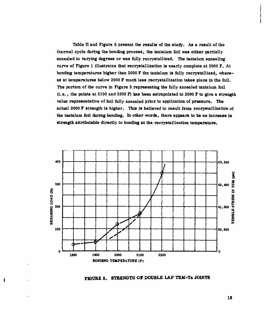
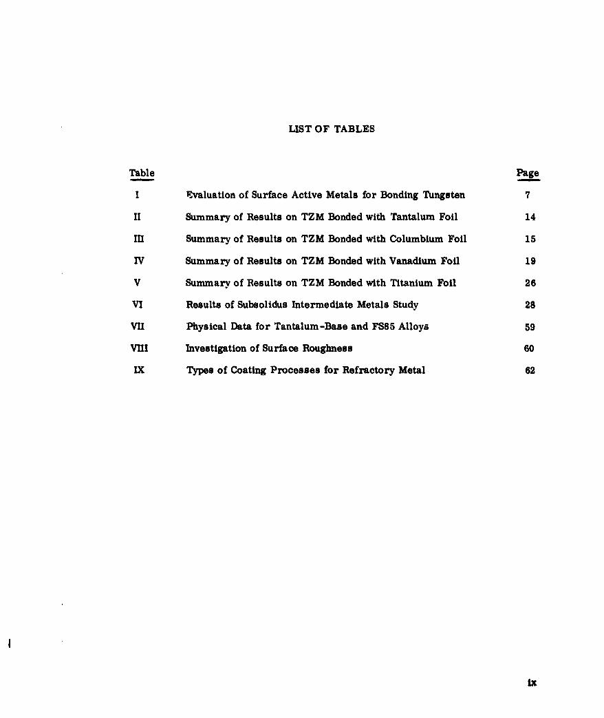
Table II and Figure 5 present the results of the study. As a result of the
thermal cycle during the bonding process, the tantalum foil was either partially
annealed to varying degrees or was fully recrystallized. The tantalum annealing
curve of Figure 1 illustrates that recrystallization is nearly complete at 2000 F. At
bonding temperatures higher than 2000 F the tantalum is fully recrystallized, where-
as at temperatures below 2000 F much less recrystallization takes place in the foil.
The portion of the curve in Figure 5 representing the fully annealed tantalum foil
(i. e., the points at 2100 and 2200 F) has been extrapolated to 2000 F to give a strength
value representative of foil fully annealed prior to application of pressure. The
actual 2000 F strength is higher. This is believed to result from recrystallization of
the tantalum foil during bonding. In other words, there appears to be an increase in
strength attributable directly to bonding at the recrystallization temperature.
400 83,200
300 62,400
100~ ~ .0 0 1,2,0
0 01800 1900 2000 2100 2200
BONDIUG TEMPERATURE (F)
FIGURE 5. STRENGTH OF DOUBLE LAP TZM-Ta JOINTS
13

III
TABLE U I
SUMMARY OF RESULTS ON TZM BONDED WITH TANTALUM FOIL
Average
Number Percent Percent Breaking Standard CoefficientTemperature of Tensile Shear Load Deviation of Variation(F) Specimens Failures Failures (lb) (lb) M9
Cold worked Ta
1800 3 0 100 28 27 96 I1900 3 0 100 43 8 202000 3 100 0 115 4 32100 3 100 0 170 0 02200 3 100 0 340 82 24
Annealed Ta, same conditions of bonding.Annealed for 2 min at 2400 F.
2000 3 67 33 166 65 39
Total Specimens: 18 iParent Material: 0.012 in. TZM
Interfacial Material: 0.001 in. Ta IJoint Type: Double lap IJoint Area: 2 - 0.050 in. x 0.40 in.
Heating Time: 390 sec iPressure: 12,000 psi
Pressure Dwell: 60 sec (from 330 to 390 see) i
I
14

TABLE IH
SUMMARY OF RESULTS ON TZM BONDED WITH COLUMBIUM FOIL
Average
Number Percent Breaking Standard CoefficientTemperature of Tensile Load Deviation of Variation
(F) Specimens Failures (lb) (lb) (%)
Cold worked Cb foil.
1700 4 25 121 39 321800 5 80 230 86 371900 10 100 305 98 322000 6 100 272 115 422100 10 100 341 106 312200 6 100 376 128 342300 4 100 482 47 10
Total Specimens: 45
As above, but Cb annealed 20 mine at 2300 F.
1800 4 75 277 49 181900 7 100 341 64 192000 6 100 367 76 212100 3 100 449 59 122200 3 100 542 27 5
Total Speci ens: 23
Parent Material: 0.012 in. TZM
Interfacial Material: 0.001 in. Cb
Joint Type: Double lap
Joint Area: 2 - 0.050 in. x 0.45 in.
Heating Time: 390 sec
Pressure: 12,000 psi
Pressure Dwell: 60 see (from 330 to 390 sec)
15

600 111,00
-0 92I0
400 -7-4 -1,000
500 - - 2,500
-0 00 37, 00000. 001 In. Cb. ANNEALED 20 MIN AT 2300
o3 0. 001 in. Cb, COLD WORKER
100 ----------------- 18,500
0 - - - - 011700 1800 1900 2000 2100 2200 2300
BONDING TEMPERATURE (F)
FIGURE 6. STRENGTH OF DOUBLE LIP TZM-Cb JOINTS
16

To confirm this observed effect, similar joints were made with columbium
and vanadium foil. Up to ten specimens were made under a given set of conditions
to give the results adequate significance. The results for columbium and vanadium
are shown in Figures 6 and 7. The data are summarized in Tables III and WY. The
scatter in the results is larger than desired for the data, but failure was purposely
forced into the joint, with consequent lower reproducibility. Surface roughness and
other physical characteristics of the TZM sheets used in the program vary which
results in additional cause for scatter.
A bonding study with annealed columbium foil (2300 F, 20 min) was also per-
formed and is shown in the data summarizations. The strength of these joints was
higher than the joints made with cold worked foil. The result with columbium is con-
trary to the results with tantalum, but the series with annealed columbium foil was
made at a different time, with a different sheet of TZM, so that direct comparison
is not appropriate. However, the annealed columbium joints did not have the 1900 F
strength peak exhibited by the cold worked columbium foil joints.
The columbium and vanadium studies confirmed the results of the tantalum
study. The strength results at 1900 F for columbium and 1600 to 1700 F for vana-
dian were about one standard deviation above the extrapolated strength values for
fully recrystallized foils. Although a question may be raised regarding the extra-
polation of the curves, it nevertheless follows the general trend of values expected
from fully annealed foils.
On the basis of the work performed in the study of this concept, the following
conclusions may be drawn:
1) Recrystallization of the intermediate foil during theapplication of bonding pressures results in an in-crease in joint strength over that realized frombonding with fully reorystallized foil.
2) The advantages of bonding under conditions of re-crystallization are small, and can be equalled byincreasing the bond temperature by 50 to 150 F.
2.2.4 Effect of Induction Heating
This concept appeared to offer the possibility of speeding up diffusion bonding
because of claims (Ref. 6) that an increase of up to ten times in the diffusion rate
had been realized by high frequency heating (700 kc frequency). A program was planned
17

II
(led) WZJ. NI UBZ&LLB flISNZL
1~ I I Ie4 .4' U,
@1 U, -' 2
0 I0
---------------------------- C II
0
0I.., I
---------------- I I
------------------------------------------ IS---
----------------------------------- K I- - - - - - I------------------------- 0
-~ Io
I'
'-'i----- I----- I H
-
-~------! I- -
-~
- ------------------------------------------------------------ - - - - - I
a a(qj) uv~i ONDIYZUE '1
18

TABLE IV
SUMMARY OF RESULTS ON TZM BONDED WITH VANADIUM FOIL
Average
Number Percent Breaking Standard CoefficientTemperature of Tensile Load Deviation of Variation
(F) Specimens Failures (lb) (lb) (%)
1400 3 0 68 33 481500 8 87 241 49 201600 5 100 296 29 101700 10 100 313 74 241800 3 100 313 54 171900 7 86 325 60 182100 6 100 449 120 272300 5 100 416 130 31
Parent Material: 0.012 in. TZM
Interfacial Material: 0.001 in. V cold worked
Joint Type: Double lap
Joint Area: 2 - 0. 050 in. x 0.45 in.
Heating Time: 390 sec
Pressure: 12,000 psi
Pressure Dwell: 60 sec (from 330 to 390 sec)
19

Magnification: X250
- - -Etched: Nital + Electrolytic
Heated 10 minutes in
resistance furnace.i
DIFFUSION OF CHROMIUM ITO IRONI
FIGURE 9.1
Magnification: X2 50
Etched: NitaL + ElectrolyticNaOH
Heated 10 minutes in highIfrequency furnace.
201

to confirm the original results obtained with chromium diffusion into iron, and to ex-
tend it to chromium diffusion into nickel and molybdenum. The extension of the pro-
gram was not started because the original claims could not be confirmed using 200 kc
induction heating.
Because of the importance of temperature as a rate-controlling factor in dif-
fusion, the method of temperature measurement received prime consideration in the
design of the equipment for both induction and radiant heating. Armco iron speci-
mens (1/2 in. diameter by 1/2 in. long) plated with two mils of chromium were heat-
ed in a vacuum bell jar furnace by one of two methods: (1) by thermal radiation from
a resistance heated (60 cycle ac) molybdenum tube, and (2) by direct inducting coup-
ling with a concentration type work coil. The temperature was measured with a
calibrated optical pyrometer by sighting into a black body cavity in the end of the
specimens, thus ensuring directly comparable temperatures for all specimens regard-
less of heating method.
Figures 8 through 11 are photomicrographs of specimens heated either by induc-
tion or radiant methods at 2000 F for periods of 10 and 30 minutes. The heating method
appears to have no effect on the rate of diffusion as determined by the average thickness
of the diffusion layer between the chromium plate and the iron core. Figure 12 shows
the microstructure of a plated specimen prior to diffusion treatment.
2A plot of these data, assuming the parabolic relationship x = 4Dt to be valid, Is
shown in Figure 13. The uncertainty of diffusion layer thickness measurement can
result in a superposition of the curves for each heating method. The diffusion coeffi-
cient (D) is taken to be the slope of the straight line plot and the average experimental
value is 0.12 x 10 8cm2/sec.
The values claimed by Samuel range from 0.21 to 1.36 x 10"-cm2 /sec at 1100 C
(2012 F). Careful examination of these claims reveals that the high diffusion rate oc-
ourred only in solid-solid diffusion where the specimen was immersed in an alumina-
chromium pack. Samuel stated this pack was observed to heat in the absence of the
specimen. Suspicion that the pack heating affects the results was confirmed by data
for different sized packs surrounding the specimen, and the existence of diffusion
layer thicknesses at so-called zero time. The author claims that high frequency fields
increase the diffusion rate. This should be modified to claim that the combined action
of a high frequency field and the special chromizing pack cause the observed effect.
The experiments at Solar were conducted in hydrogen to isolate the high frequency
effect when no increase was found In the diffusion rate depending on the heating method.
depending on the heating method.
21
FIGURE 10.1
* '~ ~Magnification: X250
Etched: Nital + ElectrolyticI** . .,~ -'.NaOH
D *~.Heated 30 minutes inresistance furnace.I
DIFFUSION OF CHROMIUM INTO IRONI
AtFIGURE 11.j
Magnification: X2 50
Etched: Nital + Electrolytic
Heated 30 minutes in highfrequency furnace.
22

FIGURE 12. ARMCO IRON ASPLATED WITHCHROMIUM
Magnification: X250
* , , .Etched: Nital
1000
~ 000
S600
~400
S200 - RADIANT HEATED________ I)INDUCTJON HEATED
00- 0 020 30DIFFUSION TIME (min)
FIGURE 13. DIFFUSION LAYER GROWTH VS TIME FOR CHROMIUMINTO IRON AT 2000 F
23

I
2.2. 5 Allotropic Transformation Effects 1In the evaluation of this concept titanium foil was used as the allotropically
transforming intermediate material and TZM or D36 as the alloy to be joined. Bond 1temperatures ranging between 1425 and 1825 F were selected so that bonds could be
made at temperatures which would encompass the titanium transformation at ap- 1proximately 1620 F. Double lap joints were made and the strength of the joints was
determined at room temperature with a Hounsfield tensiometer. IThe D36 alloy had originally been selected for the performance of this study
and single lap joints were made with an intermediate of one thickness of 0.3 mil Ititanium. Bonds were made at 1570 F and 3,000 psi in 30 seconds. Subsequent test-
ing of these joints resulted in failure in the six mil D36 in all cases (Fig. 14). It was
necessary to obtain joint failure to determine any effects caused by the transformation.
Since it was impractical to reduce the joint area, and no thicker D36 was available at the
time, 12 mil TZM was substituted for the D36.
I
Bonded with titanium foil at 1570 F for 30 seconds under 3000 psi.
Failure occurs in D36 in each case.
FIGURE 14. DOUBLE LAP SHEAR SPECIMEN OF D)36
24I

Two series of tests were performed with the TZM-Ti system. The results
of these tests are shown in Figure 15 and Table V. The difference in strength re-
sults, between the two series of tests, is apparently caused by the difference in
bond areas used in the two series. However, this difference did not affect the valid-
ity of the tests.
Soo
400
., SERISI
300..'
200
100------------- ---
100
01400 1500 1600 1700 180
BONDING TEMPERATURE (F)
FIGURE 15. STRENGTH OF TZM-Ti DOUBLE LAP JOINTS
26

I
TABLE V I
SUMMARY OF RESULTS ON TZM BONDED WITH TITANIUM FOIL
IAverage
Number Percent Breaking Standard CoefficientTemperature of Tensile Load Deviation of Variation
(F) Specimens Failures (b) (lb) (%)
SERIESI I1425 3 67 305 67 221525 3 100 288 66 231625 5 100 306 46 151675 5 100 335 24 71725 4 100 300 17 61825 3 100 318 16 5
Parent Material: 0.012 in. TZM IInterfacial Material: 0.0003 in. Ti (cold worked) (three thicknesses)Joint Type: Double lapJoint Area: 2 - 0.050 in. x 0.45 in.Heating Time: 390 secPressure: 12,000 psiPressure Dwell: 60 sec (from 330 to 390 sec)
Atmosphere: Ti gettered A
SERIES II I1570 5 40 100 35 351620 4 25 108 34 321670 4 50 164 19 111720 5 100 146 30 21
Same as for Series I, except: IInterfacial Material: 0.0003 in. Ti (cold worked) (one thickness)Joint Area: 2 - 0.125 in. x 0.0625 in.Pressure: 10,000 psi J
I
26

The allotropic transformation in pure titanium occurs at 1625 F, but the
original (Series I) data obtained in this program indicated that an increase in bond
strength occurred at a bond temperature of 1670 F. An examination of the Ti-O
and Ti-N constitution diagrams indicated that as little as seven micrograms of
either gas in the titanium used in the bond area could result in the transformation
being raised from 1625 to 1675 F. It was, therefore, felt that the effect observed
at 1670 F resulted from the allotropic transformation.
A second series of tests (Series I) was then performed to confirm the
original results. The temperature range of investigation was extended to ensure the
inclusion of any transformation effects which may have fallen outside of the original
temperature range. Also, three thicknesses of 0.3 mil titanium foil were used in
the joint so that the results obtained could be more directly compared with those of
other types of joints prepared with one mil foils.
The Series I results confirmed the strength peak at about 1675 F, and, in
addition, indicated a possible peak at 1425 F. This latter peak was probably
caused by the recrystallization of the titanium foil during bonding and is identical
to the effect studied in Concept 3. The increase in strength at the allotropic trans-
formation (1675 F) is not very significant, since it increases the strength of the
joint only 14 percent.
A slight increase in joint strength occurs at the allotropic transformation
temperature of titanium. This increase may be caused by a superplasticity effect
which may occur during the transformation, as discussed in Section 2.1. The
increase would result in more complete mating of the titanium with the TZM surface,
thus increasing the bond strength.
2.2.6 Subsolidus intermediate metals
The Zr-4.5 Cr alloy has a solidus temperature of 1300 C (2370 F), and is com-
patible metallurgically with columbium. In this study 0.14 mil zirconium foil was
electroplated with sufficient chromium to give a Zr-4.5 Cr alloy after a diffusion
treatment. It was expected that bonding near the solidus temperature of this alloy
would result n a substantial reduction of the required bonding pressure.
27

III
TABLE VI I
RESULTS OF SUBSOLIDUS INTERMEDIATE METALS STUDY
AverageBonding Breaking
Temperature Pressure Number of Load(F) (psi) Specimens (lb)
Interfacial material: 2000 5000 3 4060. 14 mil zirconium -
4.5% chromium alloy 2200 5000 1 405
2200 1000 1 460
Interfacial material: 2000 3000 1 90 INone (self-bond)
Interfacial material: 2000 3000 1 0Tin plate on D36
Interfacial material: 2000 1000 1 224Tin plate on copperplate on D36
Interfacial material: 2000 3000 2 290 1Copper plate on D36
2000 3000 2 Joints meltedat 1825 F under15 psi load.Possibly hotshort. I
Parent Material: 0.012 in. D36
Joint Type: Double lap IJoint Area: 2 - 0.050 in. x 0.45 in.
Heating Line: 390 sec
Pressure Dwell: 60 sec (from 330 to 390 sec)
28 I"

Bonding of the D36 with the alloy foil resulted in strong joints, and failure
occurred in the D36 under all bonding conditions. Since it was impractical to adjust
the joint area to give joint failure, this course of study was abandoned and the colum-
bium tin system was studied.
The solubility of tin in columbium is approximately 10 percent. The system
has only one intermetallic compound, and below 30 percent tin there are no liquid
phases below 3600 F. Although the tin would be liquid at the anticipated bonding tem-
peratures, subsequent diffusion during bonding was expected to remove the liquid
phases. Tin was plated on the D36 and although the plate was poor, a sufficient coat-
ing of tin was obtained to perform the experiments. The use of tin as an intermediate
did not result in a bond.
To substantiate these results, tin was plated over a copper flash since copper
plated rather well on the D36, and tin plated well on the copper. Fairly good bond
strength was obtained, but subsequent tests with copper alone indicated that the cop-
per caused the observed joint strengths.
The D36-Cu combination was developed further to see what merit it may have
had, since no constitution diagram was available on which to predict possible results.
Elevated temperature separation tests, under a 15 psi shear load in the joint, result-
ed in separation of the joint at about 1825 F. There were also indications that diffusion
of copper into the D36 produced hot short properties in the D36. Thus, this system
was also abandoned. The results of these investigations are shown in Table VI.
In conclusion, the lack of systems metallurgically compatible with columbium
will prevent complete evaluation of this concept. The difficulties of control in such
systems, e.g., W-Ni-W, to prevent failure at intermediate temperatures has led to
a decision to abandon this approach.
2.3 DISCUSSION OF RESULTS
The purpose of this work has been to uncover methods to activate the diffusion
bonding process. Six concepts have been tested with the results reported earlier. In
summary these results are:
29

Concept 1.- Use of surface active elements. Nickel, platinum, palladium, jand rhodium permit rapid bonding of tungsten under conditions where no bonding oc-
curs in the absence of these metals. Ruthenium and rhenium are not effective. These i
four metals will be used for bonding tungsten in Phase II.
Concept 2.- Use of diffusion aids. Boron coatings on tantalum were selected Ito investigate this concept. Results showed that this system did not accelerate bond-
ing and no further work is planned in Phase H. I
Concept 3. Effect of cold work. When recrystallization occurs during the
bonding process, enhanced bond strengths result. The effect is small, and it is not Iplanned to exploit this effect in Phase II work. I
Concept 4. Effect of induction heating on diffusion rate. This effect which
was claimed to cause up to tenfold increase in diffusion rate could not be confirmed.
Concept 5. Effect of allotropic transformation. A small effect has been
found at the allotropic transformation of titanium, but it is too small for practical !
use. Certain theoretical studies on superplasticity suggest ways to enhance the
effect, and these will be investigated in Phase 1I. 1Concept 6. Subsolidus effects. It has not been possible to find entirely suit-
able systems to exploit this effect, and no further work is planned in Phase II. IThe work on the evaluation of concepts showed other problems in these dif- j
fusion bonded joints. The major problem revealed has been the poor performance
in "peel". This term is used in the same sense as in the adhesive bonding field and
implies resistance to the application of a torque about the line of the joint. It must
be emphasized that non-optimum conditions have had to be used throughout the con-
cept evaluation work to avoid testing the foils instead of the joint. An overlap of
0.050 inch appears to be the minimum that can be used, but to force failure into the
joint the shear strength of the bond must be less than one eighth that of the foil
(0.012-inch). Certain evidence suggests that the strength of optimum diffusion
bond is low when a stress is applied normal to the bond, although the bond may
have sufficient strength in shear to cause typical tensile failures of the refractory
metal foil. Tis problem will be examined in more detail in Phase II of the program.
30 1

III. WORK ON PHASE II - PRINCIPAL FABRICATION EFFORT
The work in this phase will lead to the development of diffusion bonding processes
for the refractory metals. Major efforts will be applied to several tasks:
1. Joint Design. A survey of refractory metal structures has been madeand joint designs are based on this survey.
2. Development of Tooling. Included in this task will be an experimentstudy of tooling parameters as well as the design and construction oftooling.
3. Selection and Properties of Alloys. Base line data will be gatheredon the properties of selected refractory alloys.
4. Bonding Investigation. The development of bonding processes will beaccomplished in this task.
5. Coating Investigation. Some of the factors to be included in this taskare the relationship between coatings and joint design, the coating ofjoints, and the testing of coated joints.
6. Testing of Joints. Considerable test work will be performed in thisprogram so that the selection of meaningful tests is extremely impor-tant. The significance of tests will be examined in this task.
3.1 JOINT DESIGN
One objective of the work being done on this program is the development of
efficient joint configurations for high temperature structures through the use of dit-
fusion bonding. To assure the development of a joint which will be representative
of those required on future Air Force vehicles, a survey of trends in high tempera-
ture structural systems has been performed.
The survey of structural systems was conducted within the material limita-
tions imposed by this contract. Specifically, the structures investigated must:
9 Use refractory metals
e Operate between 2000 and 4000 F
* Use material gages from 0.006 to 0.012 inch
31

1I
The structural requirements associated with various current Air Force sys- I
tems were evaluated and compared with the capabilities of high temperature struc-
tures and materials. Structural systems which hold promise for future use were I
selected for further evaluation. Typical joint requirements were then selected from
these structural systems. I3. 1. 1 Survey of Structural Systems for High Temperatures
Work in support of Dyna Soar, ASSET and Spaceplane was reviewed, as well Ias recent development programs in high temperature structures. The combination
of temperature and material thickness parameters mentioned above eliminate all
structures other than external surfaces on glide re-entry vehicles. The various ap-
proaches to the design of a high temperature metallic structure for a glide re-entry Ivehicle can be categorized as:
" Hot monocoque I" Radiation shields plus insulated, or insulated and cooled
substructure
These approaches are illustrated below. IHot Monocoque Structure
Hot monocoque structures are characterized by systems which employ the hot Iexternal surface as the load-carrying surface. Cooling is not used, and insulation
behind the structure serves only to protect payload or fuel from excessive heating. ISince the external surface must take all loads, this surface must be rigid. Relief of
thermal stresses by floating panels and corrugations becomes difficult. Thermal Istresses become severe as the maximum operating temperatures become higher and
the system weight begins to climb. Therefore, if this system is to be competitive
with other forms of hot structure, it will probably be used at the lower end of the high
temperature range.
Structural systems falling into the hot monocoque category are exemplified by
work conducted recently on two development programs. I
3

Refractory Metals Structural Development Program -AF33(616)6578 - McDonnell and General Electric
Manufacturing Method and Design Procedures of BrazedRefractory Metal Honeycomb Sandwich Panels -AF33(657)7276 - Martin Marietta Corporation
McDonnell-General Electric Program. The use of skin-spar construction was inves-
tigated, leading to the design, fabricating, and testing of a typical fin-rudder sectionfor an advanced vehicle. Calculated surface temperatures would approach 2500 F during
re-entry. Final component substructure is shown in Figure 16. Typical skin panels are
shown in Figure 17. Both columbium alloys (FS82 and F48) and molybdenum alloys (Mo-5Zr
and TZM) were considered.
RUDDER
~HINGE LINE
FIGURE 16. TYPICAL SUBSTRATE FOR REFRACTORY METAL HOTMONOCOQUE CONSTRUCTION
33

I• I
1
/ , 1I
II
FIGUE I. TPICL CORUGTIO-STFFEND PNEL FO REFACTRY ETAHOT MNOCOUE CNSTRCTIO

Various designs of rigid surface panels were considered, and all resulted in
failures due to inability to accomodate thermal expansion. The final panels shown
in Figure 17 were designed to accept mainly air pressure loads through corrugations,
and all other loads were reacted mostly by substructure.
Various methods were evaluated for attaching the corrugated skin panels to
the spar webs. Some of these are shown in Figure 18. The general arrangement of
the corrugated spar-panel attachment is illustrated in Figure 19.
Joints which may be suitable for use of diffusion bonding are:
* Joint of corrugation to face sheet
" Joint of doubler to corruption
" Joint of panels to spar cap
" Joint of corrupted spar web to spar cap
Martin Marietta Program. Structural panels for hot monocoque design were chosen
as refractory metal honeycomb construction. Efficient structures can be built in
molybdenum and columbium alloys. Typical face sheets are 0.010 inch with a core
of 0.002 inch. Honeycomb panels must be sealed on all edges to prevent oxidation
of the interior of the panel where adequate coating cannot be provided. Edge members
must be provided to allow joining of panels to ribs either by bolting or welding.
The fabrication of the honeycomb panel cannot be considered in this program;
sandwich construction is not a part of the contract effort. However, the methods of
panel closure and techniques for joining one panel to another or to a rib is of interest.
Current edge members and joining techniques are shown in Figure 20. The Joints
must be strong since all structural loads are carried by the external surfaces.
Sequence of fabrication and coating for oxidation protection becomes a critical factor
in determining allowable joint systems.
Radiation Shield Plus Insulated and/or Cooled Structure
Unlike hot monocoque structure, where the external structure must react all
loads while operating hot, this form of construction separates the two effects. Light
floating panels of refractory metals act as radiation shields, rejecting large quantities
35

III
CORRUGATIONSPAR CAPS I
-1 1
,/,-D OUBLERi
SG
CORRUGATIONISPAR CAPS
-2
RRUGATIONISPAR CAPS
SKIN~7( CORRUGA77ON
SPAR CAPS
-4
FIGURE 18. TYPICAL JOINT SYSTEMS OF PANEL-TO-SUBSTRUCTURE
336

-1A
A A
AAA
-2
FIGURE 19. TYPICAL SPAR-PANEL STRUCTURE-HOT MONOCOQUE COIjTRUCTION
37

IIIII
I
I
FIGURE 20. CURRENT METHODS FOR JOINING STRUCTURAL SANDWICH PANELS I
of heat back to the atmosphere. Since the panels are floating, they take only air pres-
sure loads which are light. The main load-carrying structure is located below the
shields, and often separated from them by layers of insulation. Auxiliary cooling is
sometimes employed to maintain low structural temperatures. In this fashion, both
the hot, lightly loaded radiation shields and the cold primary structure can be designed
efficiently. This type of composite structure has been shown to be extremely efficient Jfor many typical glide re-entry vehicle configurations (Fig. 21). Examples of this
type of construction investigated in the survey are: j* Manufacturing Methods for Insulated and Cooled Double Wall
Structures - AF33(600)40100 Bell Aerosystems
" Manufacturing Methods and Design Procedures for BrazedRefractory Metal Honeycomb Sandwich Panels - AF33(657)7276 -Martin Marietta Corporation
38 T

Vehicle Systems Designs
" Dyna Soar
* ASSET
" Spaceplane
To operate efficiently, the heat shield panel must be able to resist air loads
without excessive deflection. Support of the shield must be kept to a minimum to
limit the flow of heat to the cooler substructure. Rigidity becomes of prime impor-
tance under these conditions.
INSULATING PACKAGE
HETSHIELD PANEL
INNER WALL -
COOLED PRIMARY STRUCTURE
FIGURE 21. TYPICAL INSULATED AND COOLED STRUCTURE
39

11i
Current heat-shield designs fall into three categories; sandwich construction,
corrugation-stiffened flat sheet, and multiple channel. Examples of these types of
constructions are shown in Figures 22 through 26.
I40, ~I
. . I!I
i
I
I
II
FIGURE 22. TYPICAL CHANNEL HEAT SHIELDS i
I40

FIGURE 23. TYPICAL SANDWICH HEAT SHIELDS
A similarity exists between the various heat shield concepts. Joints of interestfor application of diffusion bonding processes are:
* Edge closure of honeycomb heat shields
" Joint of corrugations to face sheets
* Joint of support clips to heat-shield panel
41

"exioNAFLLASON
--T T1
I2 3 4 5 6 7 8 9 1O0 ~ 13 14N(, H FS
mexpo NAMLANO1
FIGUE 2. TYICA HEA SHELDSFORPROJCT SSE
42I

0
.001-
43

I*1
N
C')
U
II
0
I
N
IIT
I* £
N
I0
II
44

3.1.2 Discussion of Joints
The survey of typical structures for future high temperature vehicle surfaces
has led to selection of a series of Joint systems required for fabrication of these
structures. The joint systems are presented in Figure 27 for heat shields and Figure
28 for primary structure.
Heat shields of Type I are generally heavier than the others shown in Figure
27, but are currently planned for use on Dyna Soar. Using diffusion bonding, weight
savings can result from smaller laps on the corrugation and elimination of rivets
(current method of joining). Reliability becomes higher because of the simplicity of
coating the diffusion bonded assembly.
The Type II shield can be made more efficiently with diffusion bonded Joints
because of the higher panel strength obtainable with continuous seam Joints between
sheet and corrugation. Coating sequences are simplified by this procedure.
The Type III shield is currently made with bolted connections between channels
and brace. The diffusion bonded joint again eliminates weight of bolts and simplifies
coating processes.
The Type IV shield cannot be made any lighter through the use of diffusion bond-
ing. Currently, panel edges and tabs are brazed while the honeycomb panel is being
brazed. Should this process prove to be unsatisfactory, the clips and edges can be
joined by diffusion bonding.
Structural Joints are those capable of joining brazed refractory metal honey-
comb sandwich panels. The Joints must be continuous, and able to withstand high
normal and planar shear loads. Their design is particularly significant because the
theoretical efficiency of brazed sandwich construction for hot structure depends largely
on the ability to join these panels with light strong Joints. Current methods of joining
panels are welding and bolting. Welding may damage the wrought material properties
and introduce distortions. Bolting can be quite heavy. The main advantage of diffusion
bonding for these structures is the ability to fabricate stiffeners tailored to joining
panels. Such stiffeners cannot be made currently by any technique other than welding.
The ability to build up a joint of properly placed members allows a latitude in design
optimization not now available in a honeycomb structure.
45

TYPE II
SEAM OR OVERLAPPING SPOTS
SPOT OR OVERLAPPING SPOT
TYPE II1
- COONTINUOUS SEAMj
W SPOT1
TYPE I
SPOT
SPOT
TYPE IVI
100,SPOTI
SEAMI
FIGURE 27. TYPICAL JOINTS FOR HEAT SHIELDS
46

CONTINUOUS
~ BUTT JOINT
BEAM
~ BUTT OR TEE
~ BUTT OR TEE
,- CONTINUOUS EAM
TEE JOINT
BEAM
~TTU
FIGURE 28. TYPICAL JOINTS FOR STRUCTURAL PANELS
47

SINGLE LAP JOINTI
T-JOINTj
____ ___ ___ ____DOUBLE___ 1A RA
FIGUE 2. SRUCTRALELEENT ANDSTUY JINT48I

Choice of Typical Joint Systems
Based on the above discussions, a series of typical joints is recommended for
initial study on this program. These joints are shown in Figure 29, and represent
the majority of joint problems to be met in future structures.
Diffusion bonding has recently advanced to the point where it can be consider-
ed seriously for use in flight structures. Therefore, the structural systems designed
to date have not attempted to take full advantages of that joining process. As work
progresses on this program, many new ideas for efficient joining systems will be
generated, leading to effective structural joints. The joints shown in Figure 29 will
help find those systems.
3.2 DEVELOPMENT OF TOOLNG
3.2.1 Induction Spot Bonder
To accomplish solid state bonding of refractory metals, it is necessary to bring
the clean surfaces together with very intimate contact; heat to a sufficiently high tem-
perature to produce good atomic mobility; hold for sufficient time to allow diffusion to
occur; and maintain a protective atmosphere to prevent oxidation and embrittlement
of the joint materials.
A device was developed at Solar during an earlier investigation that produced
excellent joints on small lap specimens. This bonder is shown in operation in Figures
30 and 31. The bonding force is applied hydraulically through high density aluminum
oxide anvils. A protective atmosphere is maintained within a quartz tube, enclosing
the anvils and specimen, by purging with high purity Inert gas or dry hydrogen. The
specimen is heated by conduction from an nductively heated tungsten disc.
This device serves as a research tool and permits close control of temperature,
pressure, and atmosphere. Another desirable feature is the small specimen size and
the related economy when the Joining parameters of the expensive refractory metals
are being invescigated.
3.2.2 Resistance Spot Bonder
The development of equipment for th, bonding of structures on a semi-produc-
tion basis is awaiting answers to questions such as the following:
49

FIGURE 30. GENERAL VIEW OF INDUCTION BONDER
FIGURE 31. CLOSE-UP OF INDUCTION BONDER '
50

I FIGURE 32. RESISTANCE BONDER
51
DELL JAR
UPPERELECRODE OLDE
UPPER ELECTRODE HOLDERI
BELLOWSI
BASE PLATEI
EVACUATION PORTI
BALL BEARING DIE SET1
COPPER TERINAL1
10 T0N 1RAU RAM
10 TO HYDAULI RAMTEFLON INSULATION
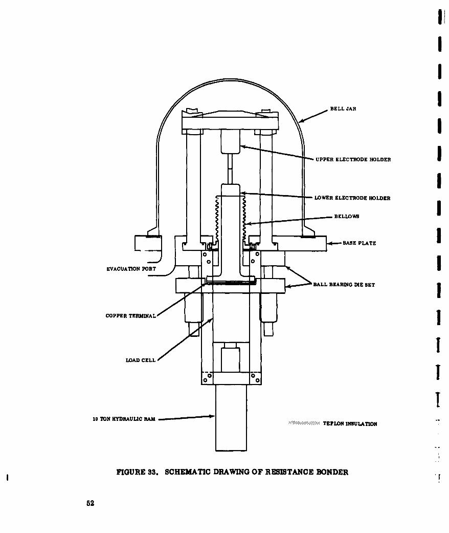
FIGURE 33. SCHEMATIC DRAWING OF RESISTANCE BONDER
52

1) What method of heating will be used?
2) What materials are best suited for anvil and electrodeconstruction ?
3) What is the maximum tolerable impurity in the pro-tective atmosphere?
Induction heating is being used with good results with the laboratory bonder
described above. Induction heating is also being considered for the prototype bonder,
but the heating of irregularly shaped sheet metal structures with close temperature
control appears impractical.
Heating by passing large, controlled quantities of electrical current through
the joint area, as in spot and seam welding, is also being investigated and appears
quite promising. The main problem with resistance heating is the choice or develop-
ment of electrode materials. They must be electrical conductors, possess good com-
pressive strength at high temperatures, and resist sticking to the material being
joined.
The resistance heated spot bonder, shown in Figure 32, is currently being used
to determine the practicability of this method of heating. Figure 33 is a schematic
drawing showing the essentials of construction and operation. The upper electrode
holder is rigidly mounted to the vertical columns and the lower electrode holder moves
vertically, guided by a precision ball bearing die set and sealed at the base plate with
a flexible metal bellows. The lower electrode is raised by the extension of a hydraulic
ram. The squeeze force is measured by a load cell located between the ram and the
lower electrode holder.
A glass bell Jar is placed over the electrodes and sealed with a gasket against
the base plate. The air is removed from the chamber with a high vacuum system. A
vacuum of 5 x 10- 5 Torr has been attained in the chamber. Bonding can be done in
high vacuum or at higher pressures by backfilling with a gas.
Three TZM double lap specimens (. 05 in. x .40 in.) have been bonded using
1.5 mil tantalum foil as a bonding aid. Bonding was accomplished by passing 1600
amperes for 60 seconds while squeezed with a force of 1000 pounds. This is equiva-
lent to 80,000 amp/sq in. and 50,000 psi. W-2Th electrodes (3/8 in. dia) attained
53
1I
an optical temperature of 1900 F during bonding and the chamber pressure increasedfrom 5 x 10- 5 to 5 x 10⁴Torr. When tested in tension at room temperature, the spei- !mens failed at 305, 345, and 295 pounds of load.
With this bonder a systematic study is planned to determine the following: I* Current-pressure-time parameters as a function of bond
strength
* The selection of optimum material for electrode construction
* The effect of impurity level of protective atmosphere on bondstrength and embrittlement I
3.3 SELECTION AND PROPERTIES OF ALLOYS
3.3.1 Background IThis program was set up to examine diffusion bonding processes for six re-
fractory metal foils in two gages. The alloys were tentatively defined by ASD as twocolumbium, two molybdenum, one tantalum, and one tungsten. The gages were to be
0.006 to 0.008 inch and 0.010 to 0.012 inch. For three reasons, it became desirable tomake certain changes in the alloy selection. These reasons were:
1. Unavailability of more advanced alloys for the initial explora-tory work.
2. Chemical similarity of current molybdenum alloys suggested 1that joining and coating problems would be similar on all alloys.
3. Chemical dissimilarity of current columbium alloys and claim- Jed effects of chemistry (such as detrimental effect of zirconiumon some coatings) suggested additional columbium alloys shouldbe studied. J
In line with these reasons, the following alloys were chosen.
Preliminary work. Choice was made on grounds of availability, back-ground information on coating and general wide experience. J
Molybdenum: TZM alloy (MO-0. 5TI-0. lZr) T
Columbium: D36 alloy (Cb-10TI-SZr)
"r
64

Tantalum: 90Ta-10W alloy
Tungsten: Pure
Advanced work (tentative selection).
Molybdenum: TZM alloy (Mo-O. 5Ti-O. lZr)
Columbium: D36 alloy (Cb-lOTi-3Zr)
B33 alloy (Cb-4V)
No selection at present time
Tantalum: Tlll alloy (Ta-8W-2Hf)
Tungsten: No selection at present time
The 90Ta-10W alloy and pure tungsten were chosen for availability to get the
program started. The stronger Tlll alloy is proposed for substitution in subsequent
work. The molybdenum alloy TZM was available at the start of the program and will
be carried throughout the work. It is proposed to substitute a third columblum alloy
instead of the second molybdenum alloy to keep the total number at six.
3.3.2 Columbium Alloys
The selection of two moderate strength columbium alloys was based on the
marked differences in chemistry. The moderate strength columbium alloys contain
Zr (D14), Ti (D36), and V (B33). Choice of a moderate strength alloy was based on
the desire to include the three principal alloying elements (Ti, Zr, and V) and led to
D36 (Cb-lOTi-5Zr) and B33 (Cb-4V). Higher strength columbium alloys generally
contain Mo (B66), W (Cb752 and Xl10), Ta (FS85), or a combination of these metals.
No selection has been made of a higher strength columbium alloy, but this decision
will be made soon in conjunction with ASD. Factors that will influence this choice
have been examined, and are believed to be:
Large percentages of tantalum are required to strengthencolumbium (FS85 has the composition Cb-28Ta-12W-1Zr),and these increase the density sharply (FS85 has a densityof 0.391 lb/cu. in. against 0.305 lb/cu. in. for B66 alloy
55
200,000
K> T-111* Ta-30Cb-7. 5
0 FS-85Ij 150,000 0 9OTa-1OW
S 100,000
'43I
,~ 50,000
400 0 400 1200 TEMERAUR 2000 2400 2800 3200I
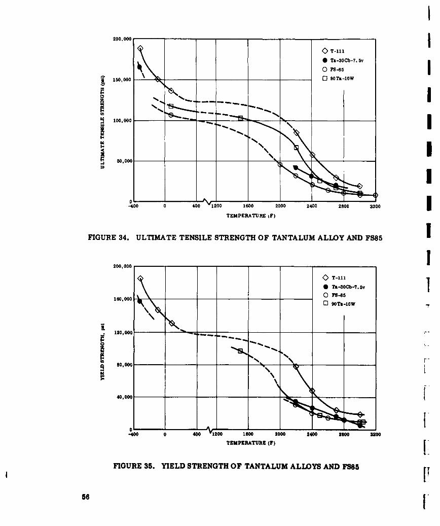
FIGURE 34. ULTIMATE TENSILE STRENGTH OF TANTALUM ALLOY AND FS85
200,000
K>T-111*Ta-3OCb-7.5v
160.000 V\0 BO-5 -
I. ~ ~ ~ ~ ~ ~ ~ ~ ~ ~ C ____ ______ ___ ____________
120,000 ~-
80,000 _____
40,000
0 -V__1-40 0 400 1200 1600 2000 2400 2800 3200
TEMPERATUR~E (F)[
FIGURE 35. YIELD STRENGTH OF TANTALUM ALLOYS AND FS85
56

(Cb-5V-5Mo-lZr). The advantages of high tantalum con-tent alloys include a higher melting point with strengthloss above 2500 F not as rapid as for tantalum-free alloys,and higher elastic modulus.
The adverse effect of large additions of Group VI elementson interstitial reactions in heat treatments, is illustratedby the irreversible embrittlement of F48 (Cb-15W-5Mo-lZr) on welding and has tended to restrict additions ofthese elements. Recently developed alloys (B66, Cb752and Xll0) have limited additions of these elements to makethe alloys weldable. Diffusion bonding will circumventthis embrittlement problem so that higher strength alloyssuch as F48 or F50 might be reconsidered if available infoil form.
3.3.3 Tantalum Alloys
The selection at the beginning of the program of 90Ta-10W on the grounds of
availability has already been discussed. The selection of the advanced alloy was
deferred until more data was available. Recent developments have made Westing-
house's Tlll commercially available on a limited basis, and the selection has been
made from four alloys available at the present time. These are: T11, 90Ta-10W,
FS85, and Ta-3OCb-7.5V. Although FS85 is basically a columbium alloy, the
mechanical properties are comparable, especially on a strength-to-weight basis.
The mechanical properties of these four alloys were used as the principal basi, for
selection.
The tensile strength, yield strength, and strength/density values are shown
in Figures 34, 35 and 36. Other miscellaneous data is listed in Table VII. The
strength properties of Tlli substantially exceed those of the other alloys in all in-
stances except that of strength/density at very low temperatures. However, Tlll
still exceeds the properties of 9OTa-10W at low temperatures, and it has excellent
ductility, 18 percent at -320 F. The recrystallization temperature of Till, (2500 F)
is acceptable. The excellent weldability of Ta-30Cb-7. 5V (probably related to its
high solubility for interstitials) is not a factor in the choice of an alloy for diffusion
bonding. Hence, Till alloy has been proposed as the advanced tantalum alloy for
this program. Delivery of 0.012 inch sheet in eight to ten weeks has been promised.
57

400, 000~T-111I
0Ta-3OCb-7.5v0 FS-85
8 0 9OTa-10W
300, 000 ______
200,000 _I
100,000I
40 0 400 1"200 1600 2000 2400 2800 3200TEMPERATURE (F)I
FIGURE 36. STRENGTH/DENSITY OF TANTALUM ALLOYSI
58

TABLE V1U
PHYSICAL DATA FOR TANTALUM-BASE AND FS85 ALLOYS
ElongationDensity Recrystallization at -320 F
Designation Composition (lb/cu in.) Temperature, (F) ()
T-111 Ta-8W-2Hf 0.604 2500 18
FS-85 Cb-27Ta-12W-0.5Zr 0.39 2400
-- Ta-3OCb-7.5V 0.426 2200
90-10 Ta-lOW 0.607 2300
3.4 BONDING STUDIES
Preliminary work was started to study the effect of surface finish and inter-
mediate foil thickness. Surface finish should be studied because the refractory alloy
sheets presently available vary from a smooth mirror finish to a relatively rough
finish characteristic of either pack rolling or extensive acid etching. The final re-
sults of this study might determine whether a standard surface finish is desirable
for more consistent difflsion bonding. It would also determine whether the local
surface cold working produced by abrading would improve the bonding process.
The second study was conducted to investigate the effect of intermediate foil
thickness on the strength of the resulting bond. Both studies are incomplete, and
more work will be done later in the program.
3.4.1 Surface Finish
The effect of surface finish was investigated with bonds made from TZM and
intermediate titanium foil. To ensure a uniform surface condition, the TZM speci-
mens were lapped on a Crane Lapmaster 12 until all the specimens had a uniformly
smooth, flat surface. Approximately 0.75 mil per side was removed from the 1/2 by
3/4 inch specimens before a uniform thickness and surface finish was attained. The
specimens were then processed with the cleaning and etching solutions normally used
in the program. A surface finish of three microinches was obtained on the TZM sur-
faces.
59

1
Bonds were made from TZM specimens having surface roughness of three,
twelve, and thirty-five microinches rms. The first was the as-lapped surface; the
other two were prepared by hand abrading the lapped specimens with 320A and 100M
abrasive papers. All of the bonds were made under the same conditions, with the re-
sults of the study being shown in Table Vm.
TABLE VIII
INVESTIGATION OF SURFACE ROUGHNESS ISurfaoe Roughness Number of Specimens Breaking Load, (Ib)
3 3 387 112 3 373 f35 3 313
As received - 35 3 330 1As received - 35 (Table V) 4 300
Parent material: 0.012 in. TZM IInterfacial material: 0.3 mil titanium foil (one thickness)
Joint type: Double lap IJoint area: 2 - 0.050 in. x 0.45 in.
Heating time: 390 sec IPressure: 3000 psi
Pressure dwell: 60 sec (330 to 390 sec)
Temperature: 1725 F JAtmosphere: Gettered A
I
60 "

On the basis of this study, the best results were obtained with the very smooth
surfaces. The results of these tests showed a 20 percent increase in bonding strength
over that of specimens made with as -received material. The surface cold work pro-
duced during abrasion did not have any apparent effect on the results. The best sur-
face condition for diffusion bonding is a smooth finish.
3.4.2 In'termediate Foil Thickness
One and three thicknesses of 0. 3 mil titanium foil were used in joining 0.012
inch TZM for this study. A bonding pressure of 12,000 psi was used, with the other
bonding conditions being identical to those in Table VIII. With one layer of titanium,
four specimens averaged 473 pounds breaking strength. With three layers of titanium,
three specimens broke at an average of 388 pounds.
These results are preliminary, but indicate that a thickness effect exists and
that more work will be necessary to determine the optimum thickness. Because of
the larger difference in strength between TZM and Ti at elevated temperatures, it is
anticipated that thickness effects will become more pronounced at higher temperatures.
3.5 COATINGS FOR JOINTS
Potential Air Force applications, for diffusion bonded refractory metal struc-
tures, are primarily in the hot parts of aerospace vehicles exposed to an oxidizing
environment. Since refractory metals are not oxidation resistant above 800 F, pro-
tective coatings must be an integral part of any hot structure. Because of the intimate
relationship between coating reliability and joint design, consideration must be given
to coating requirements at the outset of this program.
Coating processes for refractory metals are of two basic types, the first is
pack cementation, and the second Is alloying with a molten metal. In the present
stage of development, the latter is not sufficiently advanced to warrant immediate
consideration for high reliability coatings. A few of the available processes are sum-
marized in Table IX. It is not proposed to discuss the relative merits of each process
because this has been the subject of many evaluation programs including one at Solar
(Contract AF33(657)-9443) on foils of 0.002 to 0.010 inch. More important at this
stage is an ane'sis of the basic processes to determine effects that will influence the
protection of joints.
61

II
0 II I ' ' I
I a -S)a I
41 .88,. I4 A
~~~ M, g h~I I
8 8o8s8go
0 P
.8 e4. 8 8.
62 -

In the typical pack cementation process, the part is submerged in a pack con-
taining the metals to be deposited, an activator such as a halide salt, and an inert
powder such as alumina to prevent sintering. The pack is heated to a temperature
between 1800 and 2300 F for several hours. Pressures may be atmospheric or below.
At the coating temperature, a series of reactions occur which result in a net transfer
of the metallic pack material to the part. The following series of equations may be
regarded as typical of the cycle:
1. 2KF+Si . SiF 2 +2K
2. 2SiF 2 + Part -* SiF 4 + Si (part)
3. SiF 4 + Si (pack)-- 2SiF 2
The activity of the silicon on the part is reduced below that of the silicon in
the pack by the formation of silicides. The net effect is a transfer of silicon to the
part. A general appreciation of the reactions involved is important in a study of the
problems of coating joints.
Figure 37 shows typical configurations of joints. Figures 37A, B, and C show
a single lap joint with intermediate metal foil (shown much thicker than actually will
be used). The general problem of compatibility of the silicide formed on this foil with
that formed on the refractory metal must be solved first. Thus, titanium foil forms
excellent bonds with molybdenum, but the Ti-8. 5Si eutectic is at 2425 F, whereas the
corresponding eutectic with zirconium is at 2490 F. Coverage by the foil is impor-
tant. The incomplete lap shown in 37A requires the coating to have suffloient throwing
power to coat the re-entrant surfaces. The foil shown n 37C may present no problem
because the silicon will convert the free ends entirely to silicide if the thickness of
the intermediate foil is less than twice the typical coating thickness. The brittle tag
ends of the foil will break away in cleaning the part after removal from the pack,
leaving a situation similar to the ideal represented by 37B. Figures 37D and E rep-
resent two types of reinforced T-Joint. Bonding Type E at the bottom of the sheet
creates a hole the length of the joint, which cannot be adequately coated. Hence,
joint D is preferred.
63

II
A B III
I
FIGURE 37. COATING PROBLEMS WITH JOINTS _
uI0I
AB
THREE POINT LOADING TEST CANTILEVER SEAM TEST !FIGURE 38. TEST SPECIMEN DESIGNS TO DETERMINE PEEL STRENGTH
64

These preliminary considerations in the coating-joint design will be extended
as joints become available for coating.
3.6 TESTING OF JOINTS
The problem of poor "peel" strength of lap joints was discussed in Section 2.3.
Analysis of typical applications of lap joints, e.g., attachment of clips to heat shields,
shows that stresses other than pure shear will be encountered, and higher strength in
a direction normal to the lap is essential. This analysis requires a non-standard test,
and several simple test specimen designs have been considered. Figure 38 shows two
designs that are under consideration to determine peel strength of joints. Prelimin-
ary tests will be made of both designs to determine their relative merits.
65

IV. SCHEDULE AND FUTURE WORK
4.1 SCHEDULE
Figure 39 compares the schedules proposed and schedules that are being
achieved in this program. The breadth of the concepts to be evaluated in Phase I was
not known until the literature survey was complete with the result that completion of this
work was delayed by unexpected requirements of materials. Phase II has been in progress
for over a month. In general, work is on schedule.
4.2 FUTURE AORK
Work in the next quarter will include the following:
1) Study loading systems on selected joints to lead to recom-mended test procedures
2) Develop design data for prototype bonder using newly con-structed resistance spot bonder
3) Begin construction of prototype bonder
4) Develop general information on diffusion bonding process,e.g., surface finish and intermediate foil thickness effects
5) Select high strength columbium and tungsten alloys in con-junction with ASD
6) Develop specific bonding processes for each of the sixrefractory metals
7) Submit preliminary joints for coating
67

I
MONTHS AFTER CONTRACT
TASK 1 2 3 4 5 6 7 8 9 10 11 12 13 14 15 16 17 18 19 20 21 22 23 24
PHASE I
1 SURVEY OF INFORMATION .....................
2 ANALYSIS OF INFORMATION ................... I....3 EVALUATION OF CONCEPTS ...................
PHASE II
1 SELECTION OF REFRACTORY ALLOYS .......... ...
2 JOINT DESIGN 1 ................... j. . . ....
3 DEVELOPMENT OF TOOLING .........................
4 CONSTRUCTION OF TOOLING ..................
5 DEVELOPMENT OF PLAN OF ATTACK .................
6 STUDIES OF BONDING ................................... ...
7 EVALUATION OF COATINGS FOR JOINTS ............... ......... ...S TES NG OF JOINTS-- EQUPMENT SET UP ............. - ....
- - PROPOSED SCHEDULE
ACTUAL SCHEDULE I
FIGURE 39. SCHEDULE FOR DIFFUSION BONDING PROGRAM i
i
68 I.

REFERENCES
1. Metcalfe, A. G., Lindemer, T. B., Diffusion Bondg of Refractor, Metals.Solar Aircraft Company Interim Technical Documentary Progress Report 1,RDR 1322-1, dated 1 October 62.
2. Underwood, E. E., "A Review of Superplasticity and Related Phenomena."Journal of Metals (December 1962), pp. 914-919.
3. De Jong, M., Rathenau, G. W. ," Mechanical Properties of Iron and SomeIron Alloys While Undergoing Allotropic Transformation. Acta Metallurgica(Vol. 1) (1959), p. 246.
4. Presnyakov, A. A., Starikova, G. V., Izv Akad Nauk SSSR, Otdel. Tekh.Nauk, 1959, no. 1, 75.
5. Feduska, W., Horigan, W. H., "Diffusion Bonding High Temperature Alloyswith Beryllium." Welding Journal, Vol. 41 (1962), pp. 28s-35s.
6. Samuel, R. L., Samuel J. D., "The Effect of High Frequency Heating on theDiffusion Properties of One Metal Into Another." ASTIA Document 239.866
(10 April 1960) , p. 44.
69

DISTRIBUTION LIST
Department of the Air Force Department of the Army
ASD/ASRCTF (G. E. Eichelman) CommanderWright-Patterson AFB, Ohio Army Research Office
Arlington Hall StationASD/ASRC (Dr. Lovelace) Arlington 12, VirginiaWright-Patterson AFB, Ohio
Chief of Research and DevelopmentASD/ASRCE (Mr. J. Teres) U. S. Army Research and DevelopmentWright-Patterson AFB, Ohio Liaison Group
Attn: Dr. B. SteinASD/ASRCEM-1A (Mrs. N. Ragen) APO 757, New York, N. Y.Wright-Patterson AFB, Ohio
Office Chief of OrdnanceASD/ASRCM Attn: ORDTB - MaterialsWright-Patterson AFB, Ohio Department of the Army
Washington 25, D. C.Armed Services Technical InformationAgency Commanding GeneralASTIA (TISIA-2) U. S. Army Ballistic Missile AgencyArlington Hall Station Documentation and Technical InformationArlington 12, Virginia Branch
ORDAB-IEESSD/SSRTH (Lt. Col. J. Clyde) Redstone Arsenal, AlabamaAF Unit Post OfficeLos Angeles 45, California Commanding General
U. S. Army Rocket and Guided MissileAerospace Corporation AgencyAttn: Mr. Ezra Hotcher ORDXR-RGSPalo Alto, California Redstone Arsenal, Alabama
Foreign Technology Division (TD-E2B) Commanding GeneralWright-Patterson AFB, Ohio Ordnance Materials Research Office
Watertown ArsenalU. S. Air Force Directorate of RPDResearch & Development Watertown 72, MusachusettsAttn: IA. Col. J. B. Shipp, Jr.Room 4-0l-313, The PentagonWashington 25, D. C.
6593 Test GroupEdwards AFB, California

I
DISTRIBUTION LIST (Cont) IDepartment of Defense National Aeronautics & Space I
Administration
Office of the Director of Defense George C. Marshall Space Flight Center
Research & Engineering Attn: M-S & M-M/Dr. W. Lucas IAttn: Mr. J. C. Barrett Huntsville, Alabama
Room 3D-1067, The Pentagon Jet Propulsion LaboratoryWashington 25, D. C. California Institute of Technology
Attn: Dr. L. JaffeAdvanced Research Project Agency 4800 Oak Grove Drive
Attn: Dr. G. Mock Pasadena, California
The Pentagon PWashington 25, D. C.
Defense Metals Information Center Defense Contractors iBattelle Memorial Institute505 King Avenue Aerojet General CorporationColumbus 1, Ohio Solid Rocket Plant i
P. O. Box 1947Sacramento, California
Department of the Navyn Aeronca Manufacturing Company IDepartment of the Navy Attn: D. Y. PotterDepatmen ofthe avy1712 Germantown RoadOffice of Naval Research Midd2letown, Ohio aAttn: Code 423 MWashington 25, D. C. Avco Corporation
Research & Advanced DevelopmentDepartment of the Navy DivisionISpecial Projects Office Attn: S. L. Bender
Attn: SP 271 201 L . Beer
Washington 25, D. C. 201 Lowell StreetWilmington, Massachusetts
Commander Bell Aerosystems CompanyU. S. Naval Research Laboratory Technical LibraryAttn: J. E. Srawley P. O. Box 1Anacostia Station Buffalo 5, New YorkWashington 25, D. C. Bo5,ne omk I
The Boeing Company
Government Agencies Military Aircraft Systems DivisionTechnical LibraryWitchita, Kansas I
National Aeronautics and Space
Administration The Boeing CompanyAttn: Mr. G. C. Dentch Aerospace DivisionWashington, D. C. Technical Library
Seattle, Washington
-r
DISTRIBUTION LIST (Cont)
Chance Vought Corporation Grumman Aircraft CorporationAeronautics Division Bethpage, L. I., New YorkAttn: J. MillsapP. 0. Box 5907 Hughes Aircraft DivisionDallas 22, Texas Technical Library
Florence and Teale StreetsChrysler Corporation Culver City, CaliforniaMissile DivisionTechnical Library Lockheed Missiles & Space Co.P. 0. Box 2628 Materials and ProcessesDetroit 31, Michigan Attn: R. K. Titus
Sunnyvale, CaliforniaCurtiss -Wright CorporationWright Aeronautical Division Marquardt Aircraft CorporationTechnical Library Technical LibraryWood-Ridge, New Jersey 16555 Saticoy Street
Van Nuys, CaliforniaDouglas Aircraft Company, Inc.3000 Ocean Park Blvd. Martin-Marietta CorporationSanta Monica, California Technical Library
Baltimore 3, MarylandDouglas Aircraft Company, Inc.Missiles & Space Systems Division McDonnell Aircraft CorporationTechnical Library Technical Library3000 Ocean Park Blvd. P. 0. Box 516Santa Monica, California St. Louis 3, Missouri
The Garrett Corporation Melpar, Inc.AiResearch Manufacturing Division 3000 Arlington Blvd.Attn: J. L. Mason Falls Church, VirginiaLos Angeles 45, California
Narmco Research and DevelopmentGeneral Dynamics/Fort Worth Attn: R. A. LongStructures Group 3540 Aero CourtAttn: L. M. Smith San Diego 11, CaliforniaP. 0. Box 748Fort Worth, Texas North American Aviation Inc.
Technical LibraryGeneral Dynamics Corporation Columbus 16, OhioAttn: W. FeddersonP. 0. Box 2672 North American Aviation, Inc.San Diego 12, California Attn: R. R. Jansen
Los Angeles 45, CaliforniaGeneral Electric CompanyFlight Propulsion Laboratory Dept.Technical LibraryCincinnati 15, Ohio

T
DISTRIBUTION LIST (Cont) j
Northrop Corporation Westinghouse Electric CorporationNorair Division Metallurgical Engineering DepartmentAttn: B. Gaiennie Attn: E. L. Layland1001 E. Broadway Pittsburgh, PennsylvaniaHawthorne, California
Pratt & Whitney Oak Ridge LaboratoryDivision of United Aircraft Attn: W. C. Thurber ITechnical Library Chief, Metals and Ceramics Division400 Main Street Post Office Box XEast Hartford 8, Connecticut Oak Ridge, Tennessee
Republic Aviation CorporationTechnical LibraryFarmingdale, L. I., New York
RocketdyneElectrical Propulsion - NuclionicsAttn: Dr. C. J. McDole
Canoga Park, California
Rohr Aircraft Corporation ITechnical LibraryP. 0. Box 878Chula Vista, California
Ryan Aeronautical CompanvTechnical Library2701 Harbor DriveSan Diego 12, California
Sunstrand Aviation - DenverAttn: C. Hall2480 W. 70th AvenueDenver 21, Colorado
Thompson Ramo Woolridge Inc.Materials TechnologyAttn: A. H. Grobe23555 Euclid AvenueCleveland, Ohio J
II