Embed Size (px)
Citation preview

Adalight Project PackCreated by Phillip Burgess
Last updated on 2021-07-28 01:28:27 PM EDT

2344455679
121212121315182023
232425262728
2931323434
Guide Contents
Guide ContentsOverviewMeet the Pieces
Digital RGB LED PixelsArduino UnoProcessingAdalight Project PackWhy doesn't the Project Pack include the Arduino microcontroller?Wouldn’t the Arduino Mega be faster and better?
WiringDownload & Install
Download Arduino IDEDownload Processing IDEDownload Adalight ZIPProgram the Arduino
Running the SoftwareMounting LEDsOther Mounting IdeasTroubleshooting
I’ve followed the wiring diagram and successfully uploaded code to the Arduino, but nothing happens. No R-G-Bflash.A few LEDs randomly turn on when power is applied, but then nothing happens.Only the first few LEDs respond. The rest remain off or flicker randomly.The LEDs flash through the R-G-B sequence, but nothing works after that. No Colorswirl, no Adalight.Colorswirl works, but no love for Adalight.The LEDs are doing things, but it’s all flickery and twitchy and the wrong colorsI’m a Linux user and have a 32u4-based Arduino-compatible board (Leonardo, Teensy, etc.). The Arduino codeuploads OK but the Processing code can’t access the serial device.
Advanced TopicsSoftware Adjustments for Larger SetupsBuilding a Standalone Adalight ProgramThird-Party Software Options
© Adafruit Industries https://learn.adafruit.com/adalight-diy-ambient-tv-lighting Page 2 of 36

Overview
PLEASE NOTE: we’re retiring this guide but keeping the information up for anyone who might learn
from the ideas and code. It relies on an old version of Processing (at some point may stop working on
new hardware), recent operating systems are more restrictive about screen capture, and the LEDs used
are much less common now than NeoPixels. It can still run with some extra work, but there’s better
alternatives now, Google for “DIY Ambilight clone” for others’ projects!
Adalight is a do-it-yourself LED project kit that adds realtime ambient lighting effects to your computer
monitor or home theater media PC. Inspired by the Ambilight (https://adafru.it/aMz) feature of Philips’ LCD
HDTVs, Adalight adds pop to TV shows, movies or games!
Adalight relies on the fact that many people now have a computer in their living room for streaming
video. Our special software continually analyzes the content of the screen to generate an
immersive lighting display. It is not a “pass through” device and does not work with your cable TV box or
game console, only computer-driven content.
The system is built upon some of the most popular cross-platform, open-source tools, so it works equally
well on Windows, Mac or Linux computers. Technical users can climb in and make their own changes —
larger displays, multiple monitor support, or adding new features.
Every monitor is a little different, so this project requires a bit of “maker ingenuity” to complete. Please
read through the complete tutorial ahead of time for ideas on parts and tools you may need.
© Adafruit Industries https://learn.adafruit.com/adalight-diy-ambient-tv-lighting Page 3 of 36

Meet the Pieces
Digital RGB LED Pixels
Our Digital RGB LED Pixels are the ultimate Christmas lights. Under software control, the color and
brightness of every single “pixel” can be set and animated.
The 25 pixel strand included in the Project Pack is is suitable for monitors up to 27 inches (70
cm) diagonal.
Arduino Uno
© Adafruit Industries https://learn.adafruit.com/adalight-diy-ambient-tv-lighting Page 4 of 36

Arduino is the microcontroller development board that’s taken the DIY world by storm. Adalight uses an
Arduino Uno connected to a USB port to shuttle data between the host computer and the lights.
Processing
Processing is a programming environment designed for multimedia applications and first-time code
developers, and it runs equally well on Windows, Mac and Linux computers. If you’ve never programmed
before, that’s okay — we provide all the code, you just need to install it and start it running.
Adalight Project Pack
© Adafruit Industries https://learn.adafruit.com/adalight-diy-ambient-tv-lighting Page 5 of 36

�
The Adalight Project Pack bundles together one strand of our “bullet” LED Pixels (25 lights), a 5 Volt
power supply and a DC jack adapter (so there’s no soldering required). You provide your own Arduino
microcontroller — we highly recommend using the Arduino Uno. The project pack a good starter setup, or
you can choose to buy all the parts separately if you have plans for a larger or more specialized display.
As explained in the introduction, please read through the complete tutorial for an idea of what other parts
and tools you may need: USB cable, wire, tape, etc.
Why doesn't the Project Pack include the Arduino microcontroller?Arduino has become so popular among electronics hobbyists that many already own one…or even
have spares around. This also allows a choice for technical users who may want to substitute a different
microcontroller and not have to pay for an Arduino they won’t be using.
© Adafruit Industries https://learn.adafruit.com/adalight-diy-ambient-tv-lighting Page 6 of 36

� Wouldn’t the Arduino Mega be faster and better?Not in this case. The Arduino Mega has more I/O and RAM — it’s great for robots and such — but these
provide no benefit for Adalight. So if you’re buying a microcontroller specifically for this project, save
some money and get the Uno. Adalight also works 100% with older Arduinos like the Duemilanove and
Diecimila (even the earlier “168” version), if you have a retired one sitting around. Do not use an
Arduino Leonardo…this is a young product and still has some quirks preventing its reliable use with
Adalight.
© Adafruit Industries https://learn.adafruit.com/adalight-diy-ambient-tv-lighting Page 7 of 36

© Adafruit Industries https://learn.adafruit.com/adalight-diy-ambient-tv-lighting Page 8 of 36

WiringThe LED strand has a specific “input” and “output” end. The Arduino must connect to the “input” end! This
is the smaller of the two plastic end connectors, the one with the triangular “arms”:
You can press wires directly into the plug connector. This
works best with breadboarding jumper wires or solid-core
(not stranded) copper wire.
Only three wires will be used. The red wire does not
connect to the Arduino.
© Adafruit Industries https://learn.adafruit.com/adalight-diy-ambient-tv-lighting Page 9 of 36

Alternately, if you don’t want to use the “jammed wires”
trick, an optional mating connector is available in the
Adafruit shop (http://adafru.it/579). This has a plug
housing at one end and four tinned wires at the opposite
end…strip a little more insulation to press these into
Arduino pin sockets.
The red wire does not connect to the Arduino. You can
trim this wire from the mating connector or insulate it with
tape or heat-shrink tube.
Three wires connect the Arduino UNO to the input end of the LED strand: the BLUE wire can connect to
any Arduino GND pin. GREEN should connect to PIN 13 (SPI clock), and YELLOW to PIN 11 (SPI MOSI).
The RED wire is NOT CONNECTED.
Even though we don't suggest it, you can use an Arduino Mega, connect Green to 52 (SPI Clock) and
Yellow to 51 (SPI MOSI), red and blue are the same as above. With the Leonardo, unfortunately the SPI
pins are on the 6 pin programming header in the center of the board, so its really not suggested.
The extra red and blue wires are for connecting power, but we’ll do this at the other end of the strand.
Power will be connected to the same red and blue wires at the output end of the strand. Data can only go
one direction, but power can flow either way! The DC power jack has embossed “+” and “–” symbols on
the top face. Connect the RED wire to + and the BLUE wire to –. Insert the wires into the “jaws” of the jack
and cinch down the screws to hold the wires securely.
The exposed wire ends at the INPUT end will be carrying live current, so these should either be
trimmed flush with the insulation, or better yet, covered with tape or heat-shrink tube. Don’t trim
or insulate the wires at the opposite end…we need those!�
© Adafruit Industries https://learn.adafruit.com/adalight-diy-ambient-tv-lighting Page 10 of 36
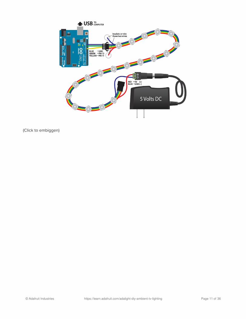
(Click to embiggen)
© Adafruit Industries https://learn.adafruit.com/adalight-diy-ambient-tv-lighting Page 11 of 36
Download & InstallWe’ll install the software next, because it’s easier to test and troubleshoot the electronics on your desk
than behind the telly!
Three packages need to be downloaded:
Download Arduino IDEFirst, download the Arduino IDE (integrated development environment) from the Arduino web
site (https://adafru.it/aHs). Select the version of the software for your computer type: Windows, Mac or
Linux. Read the Getting Started page (https://adafru.it/aMH) for an explanation of how to install the
software on your computer. It’s a little different for each of the three operating systems.
Download Processing IDENext, download the Processing IDE from the Processing web site (https://adafru.it/aMI). The first section of
the Getting Started page (https://adafru.it/aMJ) explains how to install the software.
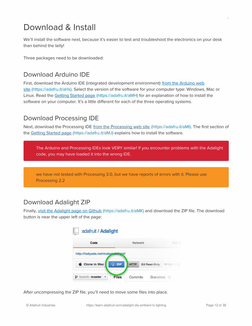
Download Adalight ZIPFinally, visit the Adalight page on Github (https://adafru.it/aMK) and download the ZIP file. The download
button is near the upper left of the page:
After uncompressing the ZIP file, you’ll need to move some files into place.
The Arduino and Processing IDEs look VERY similar! If you encounter problems with the Adalight
code, you may have loaded it into the wrong IDE.�
we have not tested with Processing 3.0, but we have reports of errors with it. Please use
Processing 2.2�
© Adafruit Industries https://learn.adafruit.com/adalight-diy-ambient-tv-lighting Page 12 of 36

If you’ve run the Arduino and/or Processing IDEs before, there will be corresponding “Arduino” and
“Processing” folders inside your personal “Documents” folder (or “My Documents” in Windows). In that
case, move the contents of the Arduino and Processing folders from the Adalight ZIP file into the
corresponding document folders.
If the Arduino and Processing folders don’t yet exist on your system, you can just copy these from the
Adalight ZIP file to your Documents folder.
The other files and folders in the ZIP file can be ignored. These are for advanced users and aren’t
essential to its use.
DO NOT use the “LEDstream_LPD8806” sketch/folder unless you are specifically using LPD8806 LED
strips in a custom build. Use just the plain “LEDstream” folder when building the Adalight Project Pack, or
for a DIY setup using similar WS2801 LEDs.
Program the ArduinoThe Arduino IDE must be installed before this step.
Connect the Arduino board to your computer with a USB A-to-B cable. When connected for the first time,
Windows users will prompted to install a driver. This is explained in the Arduino Getting Started guide for
Windows (https://adafru.it/aMR). No driver is required for Mac or Linux.
Launch the Arduino IDE. After a moment, you should see a simple blue and white window with some
buttons.
From the File menu, select Sketchbook, which should “roll over” to show LEDstream. Select this.
From the Tools menu, select Board, then Arduino Uno (or whatever Arduino board type you’re using).
Exit the Arduino and Processing IDEs if they’re running. The newly-installed folders aren’t visible
until the next time these programs start.�
© Adafruit Industries https://learn.adafruit.com/adalight-diy-ambient-tv-lighting Page 13 of 36

From the Tools menu again, select Serial Port, and then the port corresponding to your Arduino board.
Click the Upload button near the top-left of the window:
After the code is uploaded, if the LEDs are correctly wired up and the power supply is plugged in, the
LEDs should all flash red, green, then blue for about a second each, then off. This is a startup diagnostic
that tells you the LEDs and Arduino are working correctly, and are now awaiting data from the computer…
Because the Arduino stores the program in non-volatile memory, you should only need to do this upload
process once, not every time you want to use Adalight.
If the LEDs do not flash, make sure all the wiring matches the previous page, and that the power
supply is plugged in.�
© Adafruit Industries https://learn.adafruit.com/adalight-diy-ambient-tv-lighting Page 14 of 36
Running the Software
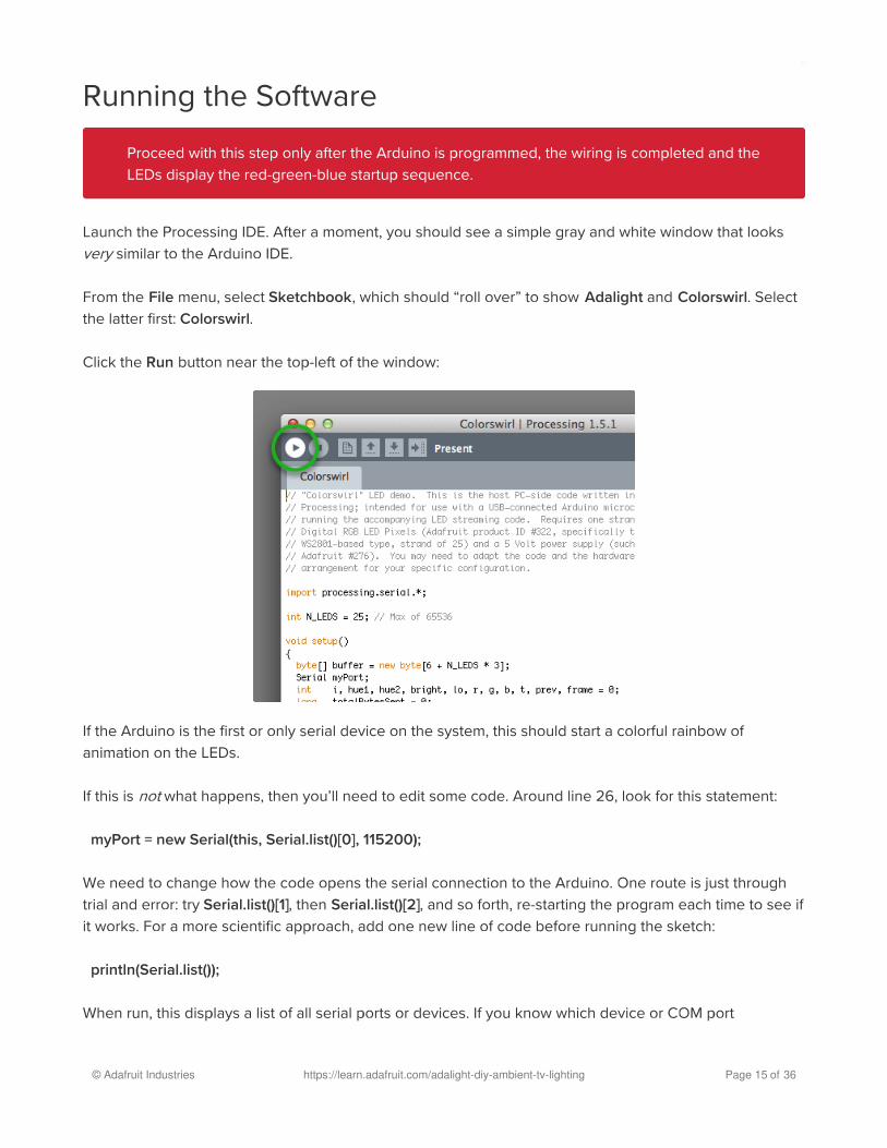
Launch the Processing IDE. After a moment, you should see a simple gray and white window that looks
very similar to the Arduino IDE.
From the File menu, select Sketchbook, which should “roll over” to show Adalight and Colorswirl. Select
the latter first: Colorswirl.
Click the Run button near the top-left of the window:
If the Arduino is the first or only serial device on the system, this should start a colorful rainbow of
animation on the LEDs.
If this is not what happens, then you’ll need to edit some code. Around line 26, look for this statement:
myPort = new Serial(this, Serial.list()[0], 115200);
We need to change how the code opens the serial connection to the Arduino. One route is just through
trial and error: try Serial.list()[1], then Serial.list()[2], and so forth, re-starting the program each time to see if
it works. For a more scientific approach, add one new line of code before running the sketch:
println(Serial.list());
When run, this displays a list of all serial ports or devices. If you know which device or COM port
Proceed with this step only after the Arduino is programmed, the wiring is completed and the
LEDs display the red-green-blue startup sequence.�
© Adafruit Industries https://learn.adafruit.com/adalight-diy-ambient-tv-lighting Page 15 of 36

corresponds to the Arduino, you can then change the original line to include this data. For example, it
might now read:
myPort = new Serial(this, "COM6", 115200);
This will be different on every system, so we can’t just tell you what to put there.
Another way to locate the port name: in the Arduino IDE, this is the port you selected in the Tools→Serial
Port menu before programming the chip.
Once you have Colorswirl working, make note of the change (if any), because the same change will need
to be made in the Adalight code.
Moving ahead…
From the File menu, select Sketchbook, then Adalight. If you changed the Colorswirl sketch to find the
serial port, make that same change to the Adalight code. Now click the Run button.
Though they’re in a jumbled mess on your desk right now, the LEDs should light up in colors resembling
the perimeter of your screen. Move some windows around the edge — you should see the LEDs react to
© Adafruit Industries https://learn.adafruit.com/adalight-diy-ambient-tv-lighting Page 16 of 36

this.
As it runs, the software performs a continual series of screen captures, averaging the pixels in blocks
around the perimeter of the screen and issuing the resulting color data to the LEDs. You can hide the
preview window and let the sketch continue working in the background. Being capture-based, it’s not tied
to any one specific media player, and most anything you can put on your display — MPEG movies,
YouTube, games and so forth — can benefit from the effect. It seems to work especially well with the outer
space sequences in Cosmos…a bit ironic in that Carl Sagan’s “Spaceship of the Imagination” from this
series featured a giant flat screen and mood lighting decades before Philips turned it into a commercial
product!
If you plan to arrange the LEDs similarly to our examples — 25 pixels in a ring, 1 pixel gap at the bottom,
with the first pixel starting just left of the gap — then nothing more needs to be changed in the software. If
using a different layout, you’ll need to make adjustments in the code. You'll find extensive notes in the
source code for making this (and other) changes.
Once all the hardware and software is working, it’s time to get crafty and mount the LEDs on the telly…
© Adafruit Industries https://learn.adafruit.com/adalight-diy-ambient-tv-lighting Page 17 of 36

Mounting LEDs
Our goal is to install the LEDs behind the screen, projecting light back and outward around the perimeter,
illuminating the wall behind.
Every TV and monitor is different, and exactly how and where to best mount the LEDs is more craft than
engineering. This is where the “maker ingenuity” comes into play!
While some of our customers have fabricated amazing metal frames and laser-cut acrylic mounting plates,
the tools and materials really don’t need to be that advanced. To prove this, our sample setup uses
nothing more than cardboard and tape! You can keep it simple or take it as far as your personal skill set
allows. It’s not rocket science!
Here we’ve fashioned an LED holder using illustration board from the nearby art supply store. Our
template is sized to match the back of the monitor, and a notch has been cut out at the bottom center to
accommodate the monitor stand:
Next, calculate the spacing for a ring of 25 LEDs. For this monitor, it worked out nicely as a 9x6 rectangle,
roughly 2" spacing, with a one pixel gap at the bottom where the monitor stand protrudes. Perfect!
Notice how the LEDs are spaced along a grid: there’s an equal number along the right and left sides, and
(except for the gap for the monitor stand) equal spacing along the top and bottom. As mentioned in a
Before mounting the LEDs behind the monitor, run the software with the LEDs loose on your desk
to confirm that everything works. This will save time and heartache in the rare event that a strand
has a defect and needs replacing.�
© Adafruit Industries https://learn.adafruit.com/adalight-diy-ambient-tv-lighting Page 18 of 36
prior page, the software may need to be adjusted for the number of LEDs across and down, if your
template is different than this.
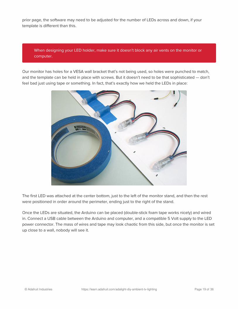
Our monitor has holes for a VESA wall bracket that’s not being used, so holes were punched to match,
and the template can be held in place with screws. But it doesn’t need to be that sophisticated — don’t
feel bad just using tape or something. In fact, that’s exactly how we held the LEDs in place:
The first LED was attached at the center bottom, just to the left of the monitor stand, and then the rest
were positioned in order around the perimeter, ending just to the right of the stand.
Once the LEDs are situated, the Arduino can be placed (double-stick foam tape works nicely) and wired
in. Connect a USB cable between the Arduino and computer, and a compatible 5 Volt supply to the LED
power connector. The mass of wires and tape may look chaotic from this side, but once the monitor is set
up close to a wall, nobody will see it.
When designing your LED holder, make sure it doesn’t block any air vents on the monitor or
computer.�
© Adafruit Industries https://learn.adafruit.com/adalight-diy-ambient-tv-lighting Page 19 of 36

(Your wiring will look a little bit different — this is our old prototype, which had different wire colors and no
convenient plugs on the ends.)
Other Mounting Ideas
Cable ties work well with pixels on their side. Holes can be made using an awl, or you can make very
clean holes using a leatherworking punch.
© Adafruit Industries https://learn.adafruit.com/adalight-diy-ambient-tv-lighting Page 20 of 36
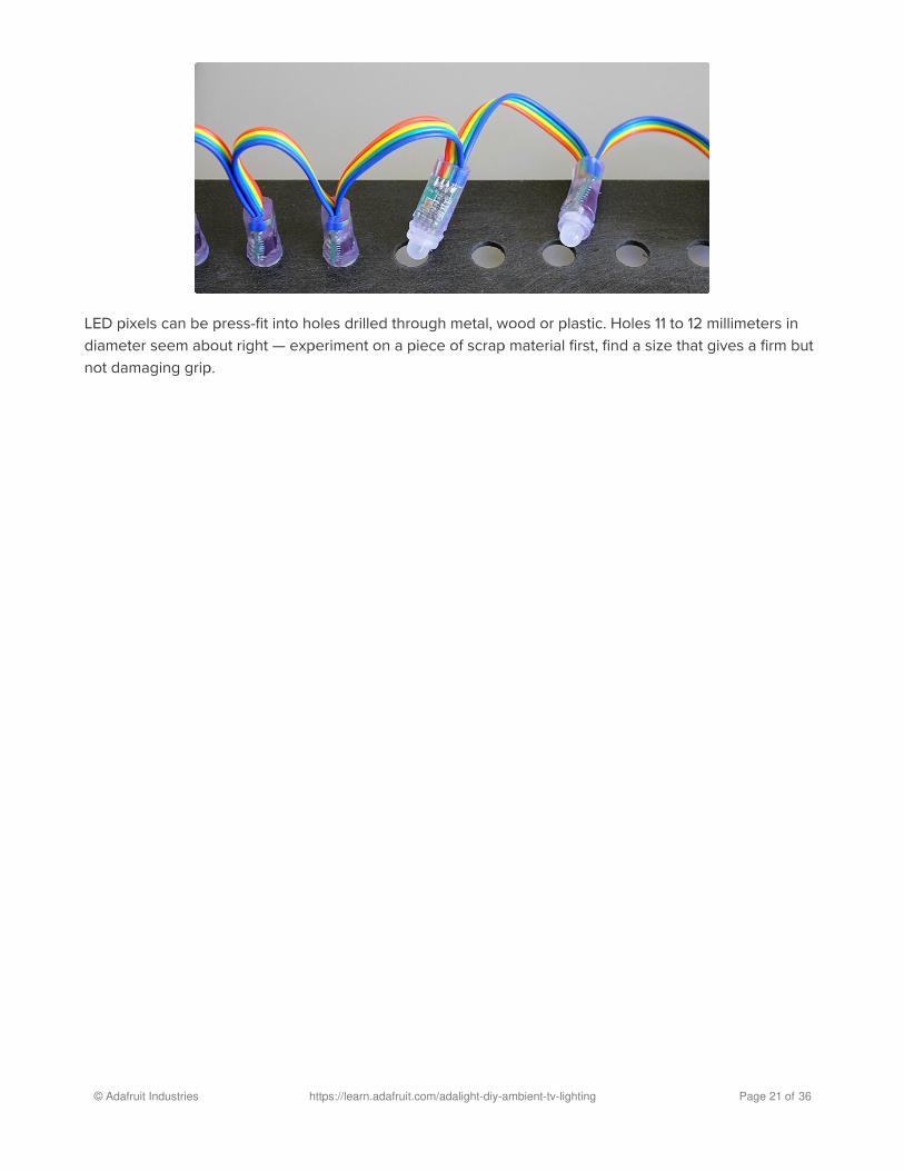
LED pixels can be press-fit into holes drilled through metal, wood or plastic. Holes 11 to 12 millimeters in
diameter seem about right — experiment on a piece of scrap material first, find a size that gives a firm but
not damaging grip.
© Adafruit Industries https://learn.adafruit.com/adalight-diy-ambient-tv-lighting Page 21 of 36
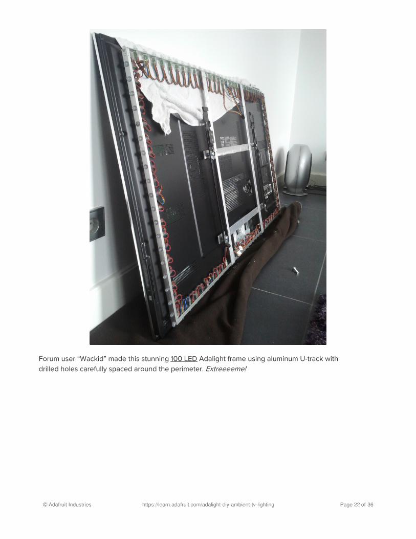
Forum user “Wackid” made this stunning 100 LED Adalight frame using aluminum U-track with
drilled holes carefully spaced around the perimeter. Extreeeeme!
© Adafruit Industries https://learn.adafruit.com/adalight-diy-ambient-tv-lighting Page 22 of 36

�
TroubleshootingAdalight depends on several parts all communicating successfully: computer, Arduino and LEDs. We
recommend following the tutorial in-order; don’t proceed to the next step until the prior step is tested and
known working. This is much easier than tracking down one small problem in the whole complex system.
I’ve followed the wiring diagram and successfully uploaded code tothe Arduino, but nothing happens. No R-G-B flash.This could be one of several problems:
Double-check all wiring. Are the green and yellow wires swapped? Is ground connected to the
Arduino?
Confirm that the Arduino is connected to the input end of the strand.
Check power supply polarity and voltage. Are + and – swapped? If you have a multimeter, confirm
5V DC output (±10%) from the power supply.
Are the power wires at the opposite end of the strand insulated or trimmed? They should not be
left exposed where they might make contact with metal, or each other.
Is the correct board type selected in the Arduino Tools→Board menu?
After checking everything, press the reset button on the Arduino. If the wiring and power are correct,
you should see the red-green-blue flash sequence.
© Adafruit Industries https://learn.adafruit.com/adalight-diy-ambient-tv-lighting Page 23 of 36

� A few LEDs randomly turn on when power is applied, but thennothing happens.The power supply is probably OK. Check for any of the following:
Double-check all wiring. Are the green and yellow wires swapped? Is ground connected to the
Arduino?
Confirm the Arduino is connected to the input end of the strand.
Is the correct board type selected in the Arduino Tools→Board menu?
Did the LEDstream code successfully compile and upload?
© Adafruit Industries https://learn.adafruit.com/adalight-diy-ambient-tv-lighting Page 24 of 36

� Only the first few LEDs respond. The rest remain off or flickerrandomly.
Inside each pixel there’s a small circuit board. Give the first bad pixel (and the one
immediately before it) a firm squeeze where the ribbon cable joins the board — it may simply be a
dodgy connection. If that works, you can either cut out the offending pixel and join the two sub-
strands, or arrange for a replacement strand if new.
© Adafruit Industries https://learn.adafruit.com/adalight-diy-ambient-tv-lighting Page 25 of 36
� The LEDs flash through the R-G-B sequence, but nothing works afterthat. No Colorswirl, no Adalight.Most likely the wrong serial port is being opened. Read through the “Running the Software” page
again, and track down the correct serial port for the attached Arduino.
© Adafruit Industries https://learn.adafruit.com/adalight-diy-ambient-tv-lighting Page 26 of 36

� Colorswirl works, but no love for Adalight.Not all software works with Adalight. Anything using hardware-assisted decoding or rendering — some
DVD player software and 3D games — bypasses the normal frame buffer and are not accessible to
code running on the computer.
Some programs will have a “software renderer” option that may help. Or try running in windowed mode
(rather than full-screen).
© Adafruit Industries https://learn.adafruit.com/adalight-diy-ambient-tv-lighting Page 27 of 36

� The LEDs are doing things, but it’s all flickery and twitchy and thewrong colorsSounds like you may have uploaded the LEDstream_LPD8806 sketch to the Arduino board instead of
the regular LEDstream. For the Adalight Project Pack, or custom builds using similar WS2801 LEDs, you
want the latter sketch, LEDstream. The LEDstream_LPD8806 sketch is only for custom builds using a
different type of LED strip.
© Adafruit Industries https://learn.adafruit.com/adalight-diy-ambient-tv-lighting Page 28 of 36

� I’m a Linux user and have a 32u4-based Arduino-compatible board(Leonardo, Teensy, etc.). The Arduino code uploads OK but theProcessing code can’t access the serial device.This is a known bug in Processing that will be fixed in the 2.0 release. In the interim, the work-around is
to create a link from the actual 32u4 serial device (typically /dev/ttyACM*) to an unused /dev/ttyS*
number, e.g.: sudo ln -s /dev/ttyACM0 /dev/ttyS42
Computers will make our lives easier!
© Adafruit Industries https://learn.adafruit.com/adalight-diy-ambient-tv-lighting Page 29 of 36

© Adafruit Industries https://learn.adafruit.com/adalight-diy-ambient-tv-lighting Page 30 of 36

Advanced TopicsThis tutorial focused on the 25 LED Adalight project pack, which is good for monitors up to 27 inches
diagonal. Some users want to build a larger rig for their living room TV. This can be done without too
much trouble…but, just like the LED mount required some creative problem solving, boosting Adalight
with additional LEDs will require some planning and a willingness to improvise in order to fit your specific
situation.
The first thing needed is a more potent power supply. The 2 Amp supply included with the project pack is
perfect for one strand of RGB pixels, but for two to six strands (50 to 150 LEDs) you’ll instead want to use
our 5 Volt 10 Amp power supply (http://adafru.it/658):
Wiring for 50 LEDs is super easy: follow the wiring diagram that was given for the standard project pack
(substituting the larger power supply above). Just as before, the DC jack adapter connects to the extra red
and blue wires at the end of the first strand of LEDs. Then plug the second strand of LEDs into the end
receptacle, and make sure all spare red/blue end wires are insulated or trimmed. Done! The second
strand receives power through the mating connector.
© Adafruit Industries https://learn.adafruit.com/adalight-diy-ambient-tv-lighting Page 31 of 36

Wiring for 75, 100 or more LEDs is a little more complicated. You’ll need some additional wire for
distributing power, and a bit of soldering may be required.
The trick here is to minimize the length that power needs to travel along the LED strands. This ensures
better brightness and more uniform color. As explained in the project pack tutorial, 5V can be applied at
either end of a strand. We exploit this in the 50 LED setup above by connecting power near the middle…
25 LEDs are powered in one direction, and 25 the other.
With more than 50 LEDs you’ll need to provide additional connections for power. This could be done at
the start of every strand…but using the same trick as above, it’s also possible to alternate strands: for 100
pixels, connect power to the wires at the end of the first and third strands, and the others will receive
power through the mating connectors.
Distribute power using extra wires connected at the DC jack. You can screw down two or sometimes three
wires in each terminal. If that’s too crowded or if you want more secure connections, solder your own “Y”
connections and insulate these with heat-shrink tube.
To connect to the strand power wires, you can either solder and insulate these connections, or use Euro-
style terminal blocks (http://adafru.it/677) — these can be clipped apart to provide two + and two –
junctions.
Software Adjustments for Larger Setups
No changes are required in the Arduino software; it’s designed to work with arbitrarily large LED setups. If
you’ve already uploaded the code to the Arduino board, you do not need to repeat this process.
© Adafruit Industries https://learn.adafruit.com/adalight-diy-ambient-tv-lighting Page 32 of 36

The Adalight Processing sketch will require modification. This is the tricky part that’s specific to your
setup…it’s not a simple copy-and-paste change, because televisions have different bezel sizes, stands,
speakers or other obstructions to take into account. Arts and crafts time!
We need to sketch out a grid that’s close to the shape of the screen, with the right number of squares
around the perimeter to match our LED strands. It’s recommended that you try a few sizes and iterations
on paper. You don’t have to put LEDs in the corner squares (some users don’t like the look and will skip
them), and in the end you might end up with a few more LEDs than grid squares — that’s okay, you can
bundle the extra unused LEDs behind the screen.
Number the columns starting from 0 at the left, and the rows starting from 0 at the top. We’ll need these
coordinates later for telling the software the position of each LED pixel. One common arrangement with
50-pixel installations has 17 squares across and 10 squares down, because it’s close to the 16:9 aspect
ratio of most HDTVs. Grid location (0,0) will then refer to the top left square, and (16,9) to the bottom right.
I like to put the first LED (the one closest to the Arduino) at the bottom center of the screen, because the
USB and power cords can be bundled alongside other cables already coming from the display. But you
can start at any position, whatever works best with your own telly.
(This is the view from the front of the screen. When installing the LEDs on the back, you’ll want to mirror
the layout, flipping everything left-to-right.)
Open the Adalight sketch in Processing and look for the following block of code starting around line 68:
The two numbers highlighted above should be changed to the width and height of your grid (17 and 10 for
© Adafruit Industries https://learn.adafruit.com/adalight-diy-ambient-tv-lighting Page 33 of 36

our sample grid above). Leave the initial '0' untouched. And you can ignore the second line (in gray) —
that’s for multiple monitor setups.
Next, look for this block of code, starting around line 87:
Each set of three numbers in curly brackets {a,b,c} represents one LED pixel, specified in-order along the
strand (the first set is pixel #1, second set is pixel #2, and so forth). The first number of each set should
always be 0, while the second and third numbers are the column and row (or “x” and “y” coordinates) of
that pixel. For our 50 LED sample grid above, the first pixel (at the bottom center) would be {0,8,9}, the
second pixel {0,7,9}, progressing around the perimeter in the order we chose earlier. (More hints: pixel #11
is at {0,0,7}, pixel #30 is at {0,12,0}, and pixel #40 is at {0,16,6}…see how it works?)
If you try to run the modified program but it throws an error, you’ve probably mis-typed one of these
number sets. Make sure there are three numbers in each set, separated with commas both between
numbers and between sets.
Building a Standalone Adalight Program
Once the Processing sketch is working to your satisfaction, you can build a double-clickable standalone
version that doesn’t require running the Processing IDE every time.
Load the Adalight.pde sketch in Processing. Then, from the “File” menu, select “Export Application.”
Select your OS type, do not check the full-screen option, then click the “Export” button. This will create an
application folder containing the standalone program and some support files. You can quit Processing
now and just use the standalone version.
We’ve experimented with a stealth windowless version of Adalight…can’t say for certain how reliable this
technique will be across all different systems, but you can try out the technique described in this this
forum discussion (https://adafru.it/aO2) and see what you get.
Third-Party Software Options
If editing Processing code isn’t your style, there are third-party software options that can also drive
Adalight.
Because we didn’t write these packages and aren’t familiar with their inner workings, we can’t provide
technical support. If you’re having trouble getting an Adalight system up and running, we’ll always ask
© Adafruit Industries https://learn.adafruit.com/adalight-diy-ambient-tv-lighting Page 34 of 36

that you start with the Processing sketch first. Once that’s working, then feel free to explore.
We’ve found Lightpack (https://adafru.it/aNp) to be easy to use with a nice GUI and good performance.
Don’t download the firmware file, just the software — with Adalight mode selected, this works with
our LEDstream sketch already on the Arduino. The Russian site for Lightpack (https://adafru.it/aNq) is a
little more bleeding-edge, and includes Mac and Linux versions.
Boblight (https://adafru.it/aNr) is another popular choice among Linux users. This is perhaps the most
complex to set up, even moreso than the Processing code. With the right plug-in it’s said to also work with
xbmc (https://adafru.it/aNs), but we’ve never gotten this far with it.
© Adafruit Industries https://learn.adafruit.com/adalight-diy-ambient-tv-lighting Page 35 of 36

© Adafruit Industries Last Updated: 2021-07-28 01:28:27 PM EDT Page 36 of 36