Embed Size (px)
Citation preview

Pr ADAOSI 0G8. NAVAL AIR DEVELOPMENT CENTER WARMINSTER PA SOFTWARE -ETC FIG 14/2 m
NAVAIRDEVCEN DYNAMIC FLIGHT SIMULATOR DESIGN AND MULTIPURPOSE C--ETCIU)NOV 79 G T THOMAS
UNCLASIFIF'ONDCAD80019I50NL
MINE PIEImEEui
ENDIE E AEX!HEoETpB

V ~REPORTNO. NADC-80019-SOp. / /
NAVAIRDEVCEN DYNAMIC FLIGHT SIMULATOR DESIGN AND MULTIPURPOSECREWSTATION CONCEPT DESIGN AND DEVELOPMENT PLAN
G. Terry ThomasSoftware and Computer DirectorateNAVAL AIR DEVELOPMENT CENTER
0Worminster, Pennsylvania 18974
1 NOVEMBER 197900 DTICTASK AREA ZRQ4106 FEB 2 61980Project No. ZROO001
Program Element 611 52N
APPROVED FOR PUBLIC RELEASE; DISTRIBUTION UNLIMITED
LPrepared forNAVAL AIR DEVELOPMENT CENTER
LA- Warminster, Pennsylvania 18974.,..
80 2 25 059

NOTICES
REPORT NUMBERING SYSTEM - The numbering of technical project reports issued by the Naval Air DevelopmentCenter is arranged for specific identification purposes. Each number consists of the Center acronym, the calendaryear in which the number was assigned, the sequence number of the report within the specific calendar year, andthe official 2-digit correspondence code of the Command Office or the Functional Directorate responsible for thereport. For example: Report No. NADC-78015-20 indicates the fifteeth Center report for the year 1978, and preparedby the Systems Directorate. The numerical codes are as follows:
CODE OFFICE OR DIRECTORATE
00 Commander, Naval Air Development Center01 Technical Director, Naval Air Development Center02 Comptroller10 Directorate Command Projects20 Systems Directorate30 Sensors & Avionics Technology Directorate40 Communication & Navigation Technology Directorate50 Software Computer Directorate60 Aircraft & Crew Systems Technology Directorate70 Planning Assessment Resources80 Engineering Support Group
PRODUCT ENDORSEMENT - The discussion or instructions concerning commercial products herein do not constitutean endorsement by the Government nor do they convey or imply the license or right to use such products.
APPROVED BY: DATE: -'4 - u
ib

Unclassified'(ICkAUTY CLASSIFICATION OF THIS PAGE (Who,. Dots Entered) __________________
READ INSTWi' 1T,'SREPORT DOCUMENTATION PAGE BEFORE COMPI FC-RM%
Design and Development P3.x S. PERFORMING OR*. REPORT NUMUER
7. AUTOR~s) . CONTRACT OR GRANT NUMIlef(s)
I. PERFORMiNG ORGANIZATION NAME AND ADDRESS 10. PROGRAM ELEMENT PRO.JECT. TASK
II.~~ CRTEAIN O&IC NAMK ANIT AUMBERS
Naval Air Development Center
CS.OTROL6TINO OFTATEMEN ADDES POi.Rpo
1. 40ISTRINGT AGNNSTAT ME 4o ADDE SS# diffeen t re a on t0,Iiflrn ffio ISRECUIYCAS o hsrpor
Unclassifie
IS. DSTRIPUEMENTANTEEN (oftis Rport
dsiution uisualDisplaSimulator Simuato Crewstalion hi
flih SiPLMlAtor OTES
S.KE ARSTRC (Continue an reverse side It netmy, and identify by black number)
,'This report presents the mission task analysis and design of theNAVAIRDEVCN Dynaic Flight Simulator, consisting of a multipurposecockpit cjritKaion, a high sustained Vg* motion system, a real worldvisual disp y system, a scene/target generati on system, acockpit/computer interface system, a problem control station and anumber of digital and analog computers.
DD ~ 147 EDT41 012OF I014 60S1 SLT UnclassifiedSECURITY CLASSIFICATION OF THIS PAGE (Who.n Dta Entered

Summary
Introduction
The general objective of this IR/IED study task is to design a DynamicFlight Simulator which can be utilized to address a wide spectrum of rapidlyapplied and sustained "G11 profiles and multistress flight mission problems.These flight mission problems would include the F-14 Spin Simulation Program,the High acceleration Cockpit Seat Program, and the V/STOL Transition Flight(From vertical to longitudinal) Program.
The specific objectives can be separated into 3 tasks. Task I presentsthe simulation mission tasks in which the NAVAIRDEVCEN should accomodate. Italso analyzes the simulator parameters required to handle the simulationmission tasks. Task II presents the NAVAIRDEVCEN Dynamic Flight Simulatormission tasks and the hardware and software requirements. Task III details adesign and development plan for the construction of a multipurpose dynamiccrewstation and cock<pit/computer interface system for the NAVAIRDEVCEN DynamicFlight Simulator. A costs and schedule estimate for the development of themultipurpose dynamic crewstation is included.
The approach that is utilized in this IR/IED study, in presentinn amultipurpose crewstation concept design, is to first address the entireNAVAIRDEVCEN Dynamic Flight Simulator design problem and then to present adevelopment plan for just the crewstation and crewstation/computer interfaceportion of the Dynamic 7light Simulator.
The Dynamic Flight Simulator utilizes a human centrifuge, illustrated inFigure 1, to provide the high sustained "g" loading environment (up to 40gs)for dynamic flight simulation. The centrifuge gondola is capable ofaccommodating the crew station, with the crew, and as a result of itsgimballing action is capable of producing almost any force vector throughhuman tolerance, varying from short duration to long term sustainingaccelerations.
The Dynamic Flight Simulator offers a number of distinct advantages, asopposed to using an aircraft, in performing rapidly applied and sustained gprofile mission tasks. These include,
o Safety-Pilot/Aircraft
o Cost
o Statistical Significance
o Repeatability
o Parameter Variability
-1-

C)
1 17~
-la A..
IU.

o Broader Data Base
o Data Handling and Analysis Techniques
o System Reliability
o Theoretical Reliability
o Theoretical understanding
o Availability
o Fuel Costs
o Weather Conditions
The NAVAIRDEVCEN is addressing the problem of more efficiently usingexisting laboratory resources to study aircraft Systems problems which havecommon application across a variety of navy platforms. These resources arecomprised primarily of existing NAVAIRDEVCEN simulation facilities, which willbe utilized for the investigation of common system problems. Commonality inactual aircraft hardware will aid in the reduction of aircraft systemprocurement expenses as well a reducing logistics problems. A subsystemlaboratories intepretability and planning board has been established ahichwill determine current and future simulation mission tasks, and identify whichNAVAIRDEVCEN facility is capable of handling specific elements of thesemission tasks. Also, coordination of each mission task element with the totalNAVAIRDEVCEN system effort is being analyzed. The Dynamic Flight Simulator isone of several simulation facilities, at the NAVAIRDEVCEP, that is beingconsidered capable of handling specific elements of these mission tasks. TheNAVAIRDEVCEN Dynamic FLight Simulator described in detail, later in this stueyreport, consists of a multipurpose cockpit crewstation, a motion system, areal world visual display system, a scene/target generation system, a
cockpit/computer interface system, a problem control station and a number ofdigital and analog computers.
The NAVAIRDEVCEN Dynamic Flight Simulator multipurpose cockpit design willhave the flexibility of being configured Into a variety of aircrafts and canutilize the basic instrumentation of that specific aircraft. The multipurposecrewstation concept, illustrated in Figure 2, consists of a general cockpitstructure and platform, housing a specific cockpit panel, anc' "J-BOX" wiringinterface enclosure. This cockpit panel assembly will be an exact replica ofthe particular aircraft involved in the mission task, including panel width,down vision, and pilot eye to panel dimension. The cockpit panel assembly,including the front panel, instrumentation, and cockpit/computer interface,will be constructed as a drawer, with the capability of being removed and anew cockpit panel assembly, with completely different aircraft features, beinginstalled. A different cockpit panel assembly will be utilized for eachaircraft type. The Dynamic Flight Simulator concept also includes amultipurpose cockpit/computer interface system which is compatable with the
-3

-
00
a0.J~f4 w
0 0 0 0 0.
wD-
\lsi

gondola slip ring wiring complement. The cockpit structure will beconstructed with enough flexibility to obtain certain features of thesimulated aircraft, such as cockpit width. The pilot consoles will beconstructed so that the forward and side angles may be varied to conform tothe simulated aircraft. Two cockpit structure stations could be utilized fora side by side cockpit configuration.
The multipurpose crewstation concept minimizes the cost of producing aspecific simulator for a specific mission task, and reduces the time fordeveloping a simulator for future mission tasks. Also, a new aircraft cockpitpanel assembly can be fabricated and wired off line, while experimental designwork is being conducted *on the existing centrifuge cockpit.

Background
The NAVAIRDEVCEN Human Centrifuge Facility was constructed in 1S52 as adynamic simulation facility to be utilized for,
o Medical Research
o Psycho-Psychological Studies
o Space Program Human Engineering
Studies
o Astronaut Training
In recent years the NAVAIRDEVCEN Human Centrifuge has been utilizedprimarily for,
o Psycho-Physiological Studies on the Effects of combined Stress onNaval aircrews.
o NAVAIRSYSCOM Sponsored Simulation Studies.
Specific recent centrifuge programs involving the dynamic simulation ofmilitary and commercial aircraft in emergency conditions include,
1. Simulation and effects of severe turbulence on jet airline pilots
2. Evaluation of a career takeoff director system in simulated night
catapult launching of the A-7 Aircraft
3. Dynamic Spin Simulation of F4 aircraft
4. Acceleration effects on the ability to activate emergency devices inthe F-4 cockpit
5. Integrated simulation of atmospheric pressures and dynamic forcesduring accidental decompression and subsequent emergency descent of highaltitude transport aircraft.
The performance and results of these specific mission tasks indicatedcertain centrifuge limitations. These limitations identified the requirementsfor,
1. Digital Computer computational capability
2. Cockpit display generator and online data acquisition/reduction
3. Improved real world visual cues
4. Aero data at high angle of attack
-6-

5. Variable force pilot stick control loader system
6. Improved centrifuge control drive algorithms
7. Improved control console
8. Solid state analog computer
9. Gimbal hydraulic drive (1st and 2nd axis)
10. Gondola third axis drive
Improvements in the Dynamic Flight Simulators capabilities are constantlybeing incorporated. The following list of improvement tasks in addition tothose detailed in this report, are currently being pursued or require fundingto accomplish.
1. Implement digital computer capability (active)
2. Purchase cockpit display generator and online dataacquisition/reduction system (active)
3. Purchase real world visual display and scene generation system(preliminary funding acquired))
4. Improve centrifuge drive algorithms (active)
5. Upgrade centrifuge control console (funding required)
6. Purchase solid state analog computer (funding required)
7. Purchase centrifuge gimbal hydraulic drive for the 1st and 2nd axis(funding required)
8. Purchase centrifuge gondola 3rd axis (funding required)
The current basic NAVAIRDEVCEN Human Centrifuge Facility designatedDynamic Flight Simulator (DFS) is described in Appendix A of this report.
This IR/IED study basically deals with the cockpit crewstation, andrequired cockpit/computer interfaces, portion of the NAVAIRDEVCEN DynamicFLight Simulator. The design of a multipurpose cockpit crewstation andcockpit/computer interface system would enable a more efficient utilization ofthe NAVAIRDEVCEN Dynamic Flight Simulator and therefore provide the capabilityof handling a larger volume and variety of dynamic simulation mission tasks.
.7-
Conclusions
The NAVAIRDEVCEN Dynamic Flight Simulator will provide the Department ofDefense with the only dynamic flight simulator in which solutions to a widespectrum of man/machine interface problems can e safely evaluated in arapidly applied, sustained g, multi-stress flight environment, throughout theentire flight regime of a modern high performance aircraft. A summary of theprimary mission tasks (requiring high sustained "g" force/motion environment),and the secondary mission tasks (not necessarily requiring high sustain "n"environment), which the Dynamic Flight Simulator should accomodate, are listedbelow. Included under the mission tasks are specific planned/proposed DynamicFlight Simulator programs.
Primary Mission Tasks
o Specific Planned/Proposal Programs
1. Survivability and Vulnerability
o F-14 Spin Simulation Program
2. Flight Performance-Transition
o V/STOL Flight Transition Program
3. Equipment Test and Evaluation
o High Acceleration Cockpit Program
o Personnel Restraint System Program
o Integrated Protective System
4. Human Factors Physiological and Environmental
o Combined Stress Program
5. Trainlng-Familiarization
o F-14 Spin Simulation Program
Secondary Mission Tasks
1. Takeoff and Landing
2. Air Combat meneuvering
3. Weapon Delivery
4. Human Factors - Task Loading
5. Human Factors - Automatic Decision Aids
-8-

It is difficult to provide an exact cost figure for a simulated aircraftsystem without specifically detailing the aircraft type and the activeinstrumentation, so the cost estimates in this report will be based on atypical flight simulator with selected instrumentation, as illustrated inFigure 3. The most immediate program which would utilize the Dynamic FlightSimulator is the F-14 Spin Simulation program. The cockpit panelconfiguration will be an exact replica of the F-14 aircraft and the selectedinstrumentation will include equipment normally utilized on a typical fixedwinded aircraft, as well as the F-14 aircraft. No equipment will be suppliedthat is specifically designed for the F-14 aircraft This equipment will hefunded by the F-14 Project Office.
Existing NAVAIRDEVCEN equipment will be utilized whenever applicable. In
addition, equipment not specifically related to proving the multipurposecrewstation concept, such as the real world visual display system, will befunded separately.
The hardware and software development cost for the design, fabrication and
checkout of the Dynamic Flight Simulators multipurpose crewstation andcockpit/computer Interface system is about 360K. A development cost breakdownincludes,
WI Software (WI.1-W1.5)Inhouse LaborEngineering (4 man months) (5K/mo) = 20.OKShop/Tech. (0 man months) (4.2K/mo) = O.OKMaterials/Computer 1O.OKContracts 0.OK
Sub Total 7=W2 Hardware (W2.1-W2.5)Inhouse LaborEngineering (18.5 man months) (5K/mo) = 102.5K
Shop/Tech (29.5 man months) (4.2K/mo) = 124KNaterials/Computer 45KContracts 60K
Sub TotalMultipurpose crewstationDevelopment Cost Total 361.5K
The multipurpose crewstation development software will be limited to aminimal amount of computer costs and software labor required to integrate,checkout and demonstrate the basic concept. The software required to drivethe human centrifuge, cockpit instrumentation, displays, flight controls etc,will have to be provided by a specific program.
In summary, the multipurpose cockpit crewstation portion of the DynamicFlight Simulator, which includes the cockpit, structure, instrumentation,displays, flight controls, panels, and cockpit/computer interface systemrequires about 361.5K in funding, so that the feasibility of the designconcept can be validated.
-9-

-2-
T- aI
Llz
10d

Recommnendat ions
The NAVAIRDEVCEN Dynamic Flight Simulator Development Plan report shoule.be utilized! to obtain funding to fabricate an experimental multipurposecrewstation prototype, so that the feasit)ility of the cesign concept can 'evalidated.
A real w,,orld visual display system should '.e purchased and utiliz!ed :tthe multipurpose crew-.station as an intEgral part of the NAVAIRDEVCENI DynamicFlig~ht Simulator.
-11
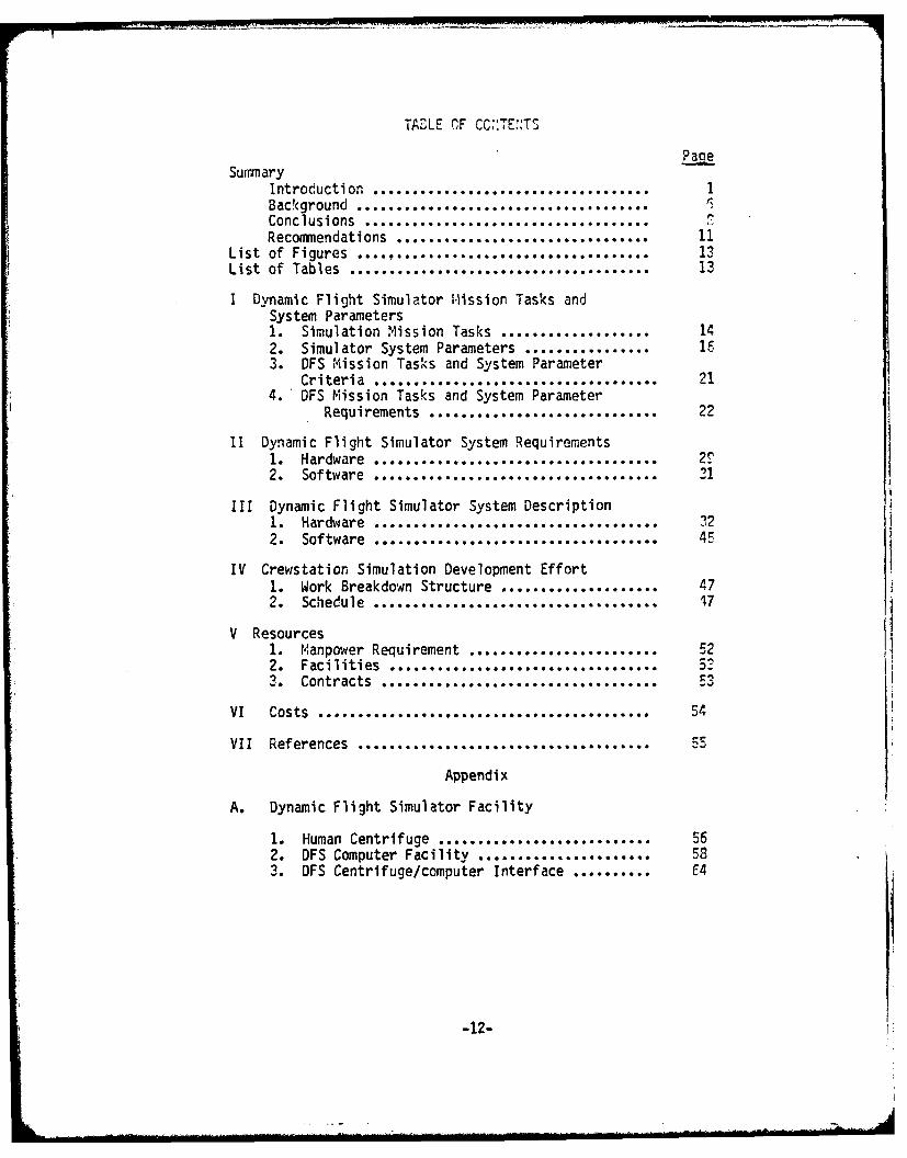
TAOLE OF CC,:TE:,Tj
SummaryIntroduction ...................................
Background . ... .........Conclusions...........................Recommendations ..............................
List of Figures .... ............................ 13List of Tables ...... ................................ 13
I Dynamic Flight Simulator Mission Tasks andSystem Parameters1. Simulation Mission Tasks ................... 142. Simulator System Parameters ................ 163. DFS Mission Tasks and System Parameter
Criteria rmns........ ........ 214.' DFS Mission Tasks and System Parameter
Requirements ............................. 22
II Dynamic Flight Simulator System Requirements1. Hardware ................................... 2T2. Software .................... 31
III Dynamic Flight Simulator System Description1. Hardware .................................... 322. Software .................................... 45
IV Crewstation Simulation Development Effort1. Work Breakdown Structure .................... 472. Schedule .................................... 47
V Resources1. Manpower Requirement ........................ 522. Facilities .. .......
Contracts ...... ..........
VI Costs .......................................... 54
VII References ......... ........................... 55
Appendix
A. Dynamic Flight Simulator Facility
1. Human Centrifuge ........................... 552. DFS Computer Facility ...................... 583. DFS Centrifuge/computer Interface .......... C4
I -12-

List of Figures
Page
1. Dynamic Flight Simulator (DFS) Human Centrifuge ....... 22. Multipurpose crewstation concept ......................3. Dynamic Flight Simulator cockpit Equipment ............ 104. Dynamic.Flight Simulator Block Diagram ................ -5. Real World Visual Display System ...................... 366. Real World Visual Display System General Features ..... 39
7. McDonnell Douglas Corporation VITAL IV SceneGeneration .......................................... 10
8. REDIFON Simulation Inc. SP-2 Scene Generation ......... 419. General Electric Co. Compu Scene Scene Generation ..... 4210. Dynamic Flight Simulator "J Box" ...................... 4411. Dynamic Flight Simulator "J Box" Wiring Scheme ........ 4612. Dynamic Flight Simulator Work Breakdown Structure ..... 4813. Multipurpose crewstation Development Schedule ......... 5114. Dynamic Flight SImulator Centrifuge ................... 5715. Dynamic Flight Simulator Computer Facility ............ 5916. Programmable Display Generator ........................ 6117. Electonic associates, Inc. Analog Computers ........... 6318. Dynamic Flight Simulator Centrifuge/Computer
Interface ........................................... 65
List of Tables
Page
1. NAVAIRDEVCEN Simulation Mission Types/Tasks ........... 152. Dynamic Flight Simulator Mission Tasks ................ 233. Dynamic Flight Simulator Parameter Requirements ....... 254. NAVAIRDEVCEN centrifuge Gondola Slip Ring Wiring
Compliment .................................. ...... . 435. Multipurpose crewstation Labor Work Breakdown .........
-13-

I Dynamic Flight Simulator Mission Tasks and System Parameters
A particular programs mission tasks and systems parameters must heanalyzed to determine if the Dynamic Flight Simulator is the type of simulatorto be utilized for the program. Also, the Dynamic Flight Simulatorscapabilities must be analyzed to determine if this program could be adequatelyperformed on this specific simulator. Obviously, a-criteria must beformulated to provide the guidance necessary to determine if a program isideally suited for the Dynamic Flight Simulator, and to determine thesimulator requirements. The following sections will detail a list of potentialmission tasks in which the NAVAIRDEVCEN Systems resources should accomodate.Also, a list of simulation system parameters will be presented. A criteriawill be formulated to determine what mission tasks should utilize the DynamicFlight Simulator. These mission tasks will be analyzed to determine theDynamic Flight Simulators hardware requirements.
1. Simulation iission Tasks
A representative list of simulation mission tasks in which theNAVAIRDEVCEN should accomodate should include those presented in Table 1.
-14-

Table 1
NAVAIRDEVCEN Simulation fission Types/Tas! s
(1) Flight Performance (Pilot Function)o Airways Navigationo Operational Navigationo Takeoff and Landingo Air Combat Maneuveringo Flight Transition (V/STOL)
(2) Tactics (Crevnen Function)o Target Trackingo Contact and Tracking Correlationo Tactical Executiono Tactical Aids
(3) Sensors (Crewmen Function)o Detectiono Detectiono Classificationo Sensor Improvement
(4) Weapons (Pilot and Crewmen function)o Weapon Launch Decisionso Target Identificationo Air to Air Weapon Deliveryo Air to Ground Weapon Delivery
(5) Hardware System.s (Equipment Function)o Vehicle Interfaceo Equipment Test Evaluation (Displays, Instruments, Flight
Controls, etc.)
(6) Software Systems (Eauipment Function)o Computer Processing Architectureo Computer Hardwareo Software Routines
(7) Human Factors (Man-Machine Systems Function)o System Control and Managemento Survivability and Vulnerabilityo Automatic Decision Aidso Task Loadingo Functional Requirements Multi-sensor Correlationo Multi-Sensor Correlationo Information Distributiono Environment Considerations
-15-

(8) Training (Training Function)
0 Familiarization
The mission tasks are somewhat general and; therefore would have to bebroken down further into sub tasks, to specifically determine the optimumsimulator to utilize with these tasks. This study, however, will deal withthese general mission tasks and attempt to provide hardware requirementguidelines to determine a criteria for the selection of the general missiontasks that should be accomodated on the Dynamic Flight Simulator.
2. Simulator System Parameters
Simulation is a never ending series of compromises because the parametersinvolved in producing a man-machine flight simulator are usually not well
* defined at the initiation of a program. Some engineers insist that thecockpit configuration of a flight simulator must be an exact replica of the
* aircraft being simulated. This is not always practical because in order thatthe simulator construction is delayed until final cockpit information isavailable, valuable fabrication time is lost and there is a possibility thatthe flight simulator will not be completed in time to have an impact on thleprogram. Other engineers feel that if the cockpit configuration of a flightsimulator were built to a generic configuration the simulation would not onlybe completed early in the program, but this flight simulator could be used forother programs. One problem with this approach is that some simulation flightmissions, such as training, require the simulator to approach an exact replicaconfiguration. Another problem is that the cockpit configuration of a fixedwing aircraft is considerably different than that of a helicopterconfiguration, which adds to the problems of using one flight simulator forboth aircraft types. Most flight simulators, including those at theNAVAIRDEVCEN, have compromised the problem by utilizing a combination of hothgeneric and exact replica cockpit configuration disciplines. Another type ofsimulator configuration, designated, Integration laboratory, utilizes actualaircraft system, usually in a generic configuration. This simulator is notutilized for man-machine experimental design functions but rather to check outthe interface of actual aircraft equipment and the software programmiinginvolved in the aircraft system.
The foliowing is a list of the primary simulator cockpit configurationutilized at the NAVAIRDEVCEN.
1. Generic (Functional Requirement Function)
2. Generic and exact replica combination (experimental design function)
3. Exact replica (training function)
4. Aircraft equipment integration (interface and software function)
The NAVAIRDEVCEN includes simulator cockpit configurations of each of* these categories. In order to address the multiplicity of systems problems a
variety of simulator configurations, utilizing a variety of simulated and* actual aircraft equipment, will be necessary. It is important to determine
the capability of each of these simulators so that a particular common missiontask can be properly located on a specific simulator, and that this simulatorhas the necessary hardware and software capability to handle the mission task.

V
In order that a man - machine flight simulator is properly developed for Pmission task several general hardware and software requirement must bespecified. A representative list of simulator Parameter information datashould include,
(1) Simulator Cockpit Configuration
o Generico Generic and Exact Replica Combinationo Exact Replicao Integration Lab
(2) Aircraft Typeo Fixed Wingo Helicoptero V/STOL
(3) Cockpit Seating configurationo Single Seato Side by Sideo Tandemo Three Crewmeno Four Crewmen
(4) Cockpit Flight Controlso Control Sticko Side arm controllero Collectiveo Throttleo Rudders
(5) Cockpit Instrumentationo Airspeed indicatoro Barometric altimetero Radar altimetero Attitude Indicatoro Horizontal Situation Indicatoro Rate-Of-Climb Indicatoro Accelerometero Angle of attacko Clock
(6) Cockpit Displayso Multipurposeo Vertical Situation Displayo Horizontal Situation Displayo Heads Up
(7) Aircraft Inflight Cueso Real World Visualo Motiono "G" Suito "G" Seat
-17-

(8) Sensorso LOFARo DIFARo CASSo MADo Radaro ESM
(9) Computerso Digital (Central)o Digital (Mini)o Digital (Microprocessor)o Analog
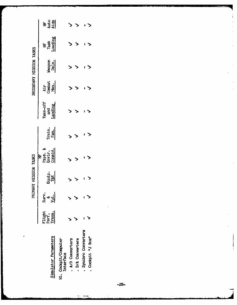
(10) Cockpit/Computer Interfaceo A/D Converterso D/A Converterso Synchro Converterso Cockpit "J Box"
After a determination has been made, regarding the general simulatorhardware and software requirements necessary to perform a particular missiontask, specific hardware and software requirement information should !tedetailed for the following simulator subsystems
o Cockpit (including instrumentation, displays, switches,indicators, communications and flight controls)
o Motiono Visual Displayo Scene/Target Generatoro Cockpit/Computer Interfaceo Problem Control Stationo Computer
This detailed simulator subsystem information should include,
(1.) Cockpit
PANEL CONFIGURATION
o Down Vision Angle (degrees)o Panel Width (inches)o Pilot Eye to Panel Distance (inches)
COCKPIT DISPLAY
o Input output signalso Display screen size (in, cm)0 Resolution (arc min)o Brightness (fL)o Contrast (ratio)o Display image sizes (in., cm)o Display functions
-18-

o Writing speed an.refresh ratio (in/usec. cm/usec)o Phospher coloro Linearity (percent)o Allowable distortion (percent)o Bandwidth (MH )o Additional features including phospher protection, high-voltage
protection, ganma correction
(2) iotion System
o Degrees of Freedomo Total payload (Ib, gram)o Motion displacement (longitudinal, lateral, and vertical) (+ in,
+ cm)
o Motion velocity (longitudinal, lateral, and vertical) (in sec,cm/sec )
o Motion acceleration (longitudinal, lateral, and vertical)(in/sec, cm/sec )
o Motion rotatlin (roll, pitch, and yaw) (degrees/sec)o Motion rotational acceleration (roll, pitch, and yaw)
(degrees/sec)
(3) Visual Display
0 Field of view (degrees horizontal, degrees vertical, ,4egreesdownward)
o Brightness (fL)o Depth of fieldo Contrast (ratio)o Exit pupil diameter (in.cm)o Picture color (black and white or chromatic)o Geometric distortion (percent)o Collimination error (arc min of convergence, divergence, and
dipvergence)
(4) Scene/Target Generator System
Computer Generated Scene
o Color (black and white or chromatic)o Input/Output signalso Special features (curved surface shading, edge smooting,
variable fog, aerial perspective, broken clouds, texturing,etc.) yes or no
o Number of display edgeso Number of stored edgeso Video raster (number of TV lines)o Scan rate (number of frames per second)o Number of point lightso Number of channelso Special-purpose computer (bit ,.,word site, number of ,..ords of core
memory, memory expandable to words, number of hardwareinstructions)
-19-

Computer Generated Image Target
o Simulated aircraft altitude (0-:', O-y m)o Simulated aircraft attitude (degrees)o Simulated aircraft angular rates (degrees/sec)o Simulated aircraft translational rates (ft/sec, m/sec)o Accuracy of simulated altitude (+ ft, + mo Accuracy of simulated altitude (T degrees)o Accuracy of translational position (± in, + cm)
Terrain Model Scene Generator Systems
o Interface definition and associated equipmento Input/output signalso Special featureso Color (black and white or chromatic)o Terrain and white or chromatic)o Terrain model scale (ratio)o Gantry displacement (longitudinal, lateral, and vertical) (+ft.
± meters)o Gantry velocity (longitudinal, lateral and vertical) (in/sec,
cn/sec)o Gantry acceleration (longitudinal, lateral and vertical)
(in/sec, cm/sec )0 Gantry accuracy (in, cm)0 Gantry minimum smooth track velocity (in/sec, cm/sec)o Optical probe field of view (degrees)o Optical probe field of view (degrees)o Optical probe movement (roll, pitch, yaw) (degrees)o Optical probe velocity (roll, pitch, yaw) (degrees/sec)o Optical probe acceleration (roll, pitch, yaw) (degrees/seco Optical probe accuracy (degrees)o Optical probe minimum smooth track velocity (degrees/sec)
High-Fidelity Target Generator Systems
o Input/output signalso Static position accuracy (yaw, pitch, roll) (degrees)o Position limits (yaw, pitch, roll) (degrees)o Maximum slew rate (yaw, pitch, roll) (degrees/sec)o Minimum slew rate (yaw, pitch, roll) (degrees/sec)o Bandwidth (rad/sec)
(5) Computer/Cockpit Interface System
The specification headings for the computer/cockpit interface system arenot included in this report.
-20-

(6) Instructor Control Station
o Display type/number0 Keyset type/number of keyso Types of instrumentso Readouts and indicatorso Playback capability
(7) Computers
o Description of processing systemo Description of display generation system0 Description of all peripherals0 Description of real-time systemo Description of interface to simulation deviceo Upper level block diagram of hardware configurationo Word lengtho Cycle time(s)o Memory capacity and characteristicso Software language capabilities0 Editing, debug, and diagnostic aidso Operating system including real-time interrupts (with
priorities) for general-purpose and symbol generationo Software/system documentation
The following general information should be requested for each of thesimulator subsystem proposed for implementation in a simulator concept:
o Manufacturer's name and model numbero Brief functional descriptiono Illustration showing the location of major componentso Overall size (ft, m?o Weight (lb, kg)0 Power requirements (kW)o Cost
3. DFS M.ission Tasks and System Parameter Criteria
This report will not attempt to list all of the specific subsystemrequirements detailed in the previous section of this report, but will presenta selected number of these requirements so that a multipurpose dynamic flightsimulator can be designed. Also, some subsystem specifications such as motionare inherent in the existing human centrifuge and cannot be easily altered.The NAVAIRDEVCEN Dynamic Flight Simulator requirements; therefore will be acombination of existing features and selected subsystem requirements necessaryto handle the proposed mission tasks.
The most important Dynamic Flight Simulator system parameter is rapidlyapplied and high sustained "g" motion, so that all mission' tasks would firsthave to be judged to determine if high sustained "g"n is a major requirement.The specific human centrifigue motion specifications are detailed in reference:and selected specifications are presented in section III of this report.
-21-
617.

The human centrifuge can also provide a multi stress environment includinnvariations in temperatures, pressures, noise, and I-uffeting. Each missiontask should be analyzed to determine if a multi-stress environment is animportant factor in the mission task performance.
Many mission tasks such as takeoff and landing, could be run on the humancentrifuge, eventhough high sustained "g" forces are not required and;therefore these missions must be considered secondary utilization tasks.Secondary tasks would have to be judged on other parameter tradeoffs such ascost, schedule, etc. Other secondary tasks might include air combatmaneuvering or task loading mission tasks, required as part of a primarymission task such as a spin simulation program.
Finally the overall NAVAIRDEVCEN Centrifuge Facility capability, describedin Appendix A, should be utilized as a trade off judging factor in theselection of the mission tasks that could utilize the Dynamic Flight Simulator.
The multipurpose crewstation cockpit configuration should utilize ageneric and exact replica combination cockpit configuration, designated in thelast section of this report as an Experimental Design Simulator. Research hasgenerally shown that functional similarity between aircraft and simulatorproduces greater pilot acceptance and therefore aids in his motivation.
The cockpit panel should maintain as minimum, the correct Iil Standarddown vision, panel width, pilot eye to panel and ejection envelopedimensions. The cockpit panel instrument and display layout should alsoclosely resemble the specific simulated aircraft.
High sustained "g" requirements indicates the simulation of a fixed wingaircraft; however the Dynamic Flight Simulator could be utilized for certainmission tasks with a helicopter or V/STOL cockpit configuration. The type ofaircraft utilized in the Dynamic Flight Simulator will dictate therequirements for instrumentation, flight controls, displays, etc. The cockpitseating configuration will be limited to single seat and side by side becauseof space limitations in the centrifuge gondola. The aircraft inflight visualand motion cues will be dictated by the mission tasks. Sensor simulationmission tasks, with the possible exception of tactical radar, should probablynot be done on the Dynamic Flight Simulator.
4. DFS Mission Tasks and System Parameter Requirements.
Representative simulation tasks of the type that should be addressed atthe tNAVAIRDEVCEN are presented in table 2, along with those primary andsecondary mission tasks which could utilize the Dynamic Flight Simulator.
-22-

Table 2 Dynamic Flight Simulator ,:ission Tasks
Dynamic Flight SimulatorSimul ati on
Fission Tasks Primary SecondaryTasks Tasks
(1) FLIGHT PERFOR.ANCEo AIRWAYS NAVIGATIONo OPERATIONAL NAVIGATIONo TAKEOFF AND LANDINGo AIRCOMBAT MANEUVERINGo TRANSITION (VERTICAL TO FORWARD)
(2) TACTICSo TARGET TRACKINGo CONTACT & TRACKING CORRELATIONo TACTICAL EXECUTIONo TACTICAL AIDS
(3) SENSORSo DETECTIONo CLASSIFICATIONo SENSOR IMPROVENIENT
(4) WEAPONSo WEAPON LAUNCH DECISIONSo TARGET IDENTIFICATION -o AIR TO AIR .EAPON DELIVERY - ¢o AIR TO GROUND WEAPON DELIVERY
(5) HARDWARE SYSTEMSo VEHICLE INTERFACEo EQUIPMENT TEST & EVALUATION
(6) SOFTWARE SYSTEMSo COMPUTER PROCESSING ARCHITECTURE - -o COMPUTER HARDWARE - -o SOFTWARE ROUTINES - -
(7) HUMAN FACTORSo SYSTEM CONTROL AND MANAGEMIENTo SURVIVABILITY AND VULNERABILITYo AUTOMATIC DECISION AIDS -o TASK LOADING -o FUNCTIONAL REQUIREMENTS -o MULTI-SENSOR CORRELATION -o INFORMATION DISTRIBUTIONo ENVIRONM.ENTAL CONSIDERATIONS V
o PSYCHO-PHYSIOLOGICAL STUDIES V i
(8) TRAININGo FAMILIARIZATION
-23-

It would be useful at this point to discuss planned/proposed specificprograms that might utilize the Dynamic Flighit Simulator, so that the primaryand secondary mission tasks, selected in Table 2, might be reinforced.
(1) The F-14 Spin Simulation Program requires the hi'Ph sustained "g"environment of the centrifuge, since many spins occur in this environment.This program also requires some limited air combat maneuvering capability,since inadvertent spins occur during high task loading situations, during aircombat maneuvering missions. Also, certain aircraft equipment involved in theoverall spin problems; such as cockpit, displays, warning indicators, engineinstruments etc., can be tested and evaluated in a simulated spinenvironment. Spin familiarization training is another useful mission taskthat can be accomplished on the centrifuge.
(2) The V/STOL Flight Transition Program (Vertical to For,.-ard) willrequire the continued motion conditions that are available on the humancentrifuge.
(3) The High Acceleration cockpit Seat Program requires the highsustained "g" environment of the centrifuge, for the test and evaluation ofthe crevwans rotating seat, during a high acceleration flight maneuver.
(4) The Personnel Restraint System Program requires the high sustained"g" environment, of the centrifuge, for the test and evaluation of variouscrew restraint systems.
(5) The Combined Stress Program requires a m ulti-stress environmentinc'uding high sustained "g" to determine the Psycho-Physiological effect onaircre, perfor-ance during various mission tas,<s.
T:he general Simulator parameters necessary to determine the Dynamic Flif'tSimulctor requirements are presented in tabl2 3 and the parameters requiredfor the following primary and secondary mission tashs are indicated.
Primary Mission Tasks
o Flight Performance Transitiono Survivability and Vulrerabilityo Equipment Test and Evaluationo Human Factors - Psycho - Physiological and Environmental
Considerationso Training - Familiarization Tasks
Secondary Mission
o Takeoff and Landingo Air combat Maneuveringo Weapon Deliveryo Human Factors Task Loadingo Human Factors Automatic Decision Aids
-24-

0 (n
aE2a >
8 ''C 8'>
f4-4
0)0
ci) a
co)
4-)
-aE- . c ~ -') Wx ).-1-4 :3 -a I '> I I >'> '*
C,()
4-4-0
ou I
4-) 0. tz1- ce... -r bD l+u .(. 0 =) C) -- . - )
CL. E C4q4) (1 0 1 0)0j ? .0.-e - 4 r~~-4
'O ).- a)) 4)) c' . d
40 = 41 )C Coo E.x 0
-25-

'I.. 02 I
0.~
I
.-
Hc .0- t.;H4 .0
00
'.4 k 490.1
4czZI
-- 26-

003
lip, I I I I I I .> a
**a(4**
ac a a a a
r4 a a a a a
a4 E .-
a3- or 1 1 1 1 t. a1M C l O
co 4.d)4) .
H- C1 V-q - H-
=~~ ~ ~ *2 * * .
c') (36-27'-
1 '>'> ">00
.0.
" CI 0 > "
-28-

II Dynamic Flight Simulator System
Requirements
1. Hardware
The Dynamic Flight Simulator System must have sufficient hardware
equipment to handle the mission tasks presented in table 2. This hardwareequipment will include,
o Multipurpose cockpit (including instrumentation, displays, switches,indicators, communications
o Motion Base Systemo Visual Display Systemo Scene/Target Generation Systemo Computer Systemo Cockpit/Computer Interfaceo Problem Control Station
The hardware requirements for each of these subsystems will he describedin the following paragraphs.
1.1 t!ultipurpose cockpit. The simulator cockpit geometry should be close toa replica of the aircraft that is being simulated. Research has generallyshown that functional similarity between aircraft and simulator producesgreater pilot acceptance, and therefore aids in his motivation. Normally theDynamic Flight Simulator will be configured as a fixed wing aircraft, but thecapability of incorporating a V/STOL or helicopter aircraft configurationshould be included. Enough active instrumentation, 6isplays, svitches,indicators and flight controls are required to perform the mission tasksoutlined in Table 2. The instrumentation should include flight instruments,such as airspeed, rate-of-climb, radar altimeter, barometric altimeter,altitude, bearing/distance/heading, accelerometer, angle of attack and turnand slip indicators and engine instruments, such as rotor speed, turbine inlettemperature, and basic fuel flow.
The number of cockpit display systems, such as a Vertical Display
Indicator or a Horizontal Situation Display Indicator, will depend on thesimulated aircraft; however the multipurpose cockpit should be flexible enoughto facilitate the required displays. The capability of incorporating a HeadsUP Display system into the cockpit should be included.
Selected switches, indicators, and panels, dictated by the type ofsimulated aircraft and the mission tasks, should he made active.
Active flight controls should include a close facsimile of the simulatedaircrafts stick, and rudder system and either a fixed wing aircrafts throttleor a helicopter collective system.
-29-

Commnunications between the multipurpose cockpit, tile instrumentationstation, computer rooms and the gondola loading platform, should '1e provieed.
A motion buffet system designed to produce the required aerodynamicbuffeting cues, during certain aircraft aerodynamic maneuvering situations,should be provided.
1.2 M~otion System
TIhe Dynamic Flight Simulator motion requirements in theory depend on themission task motion requirements; however the centrifuges motion capabilitiesare well defined, as detailed in reference a. A mission task therefore llhave to be designed according to the centrifuges current motion specifications.
1.3. Real World Visual Display System
The Dynamic Flight Simulators mission tasks require a real world visualdisplay system, which will present the proper scene/target required for eachtas'N. This scene will include, as a minimum, a horizon, some mround terrainand sky features, to allow the pilot to perform certain aerodynamicmaneuvering tasks, depending on the mission. Also, a target aircraft will !esuperimposed on the real world display during certain experimental cdosigntasks.
The real world viewing area should be as large as possible; however thisfield-of-view will be limited to the space constraints of the centrifugegondola. A high fidelity real world image should be presented directly infront of the pilot. A low fidelity real world image can be presented in thearea of the pilots peripheral vision. The Visual display system should have aresolution of at least 6 arc minutes and a brightness of at least 4 ftlamberts. A chromatic real world system is desired but not required.
The visual display system must be capable of withstanding the centrifuges10-15g dynamic loading requirements. The physical size of the real worldvisual display unit must conform to the gondolas space limitations, detailedin reference b.
1.4 Scene/Target Generation
The scene/target generation system must be capable of generating the realworld image, described in the previous section of this report. This systemmust also have the capability of updating the scene/target image, a minimum ofevery 1/30 sec, in proper perspective, to conform to the pilots aerodynamicmaneuvers. Reasonable coordination of the aircraft simulators visual andmotion cues is required.
1.5 Computer Systems
The Dynamic Flight Simulator system requires the utilization of a completecomputer facility, including analog, digital and display generationcomputers. This capabi'lity should include access, to the Computer Facilities6600 Digital Computer, EA1 Analog Computer and the IDI Display GeneratorComputer System.
-30-

1.6 Cockpit/Computer Interface
A cockpit/computer "J BOX" interface must '-e provieed, in the gorcla.This interface must conform to the centrifuge slip ring complement of inputand output wires and be capable of provieing an adequate number ofpotentiometer signals (utilized for instrumentation and flight controls),switch closures indiscretes, lamp driver outdiscretes, display signals, powerinputs and physiological outputs. Additional cockpit/computer interfaceequipment, depending on the mission task, might include analog/digitalconverters, digital to analog converters, synchro converters, displayinterface and a discrete interface.
1.7 Problem Control Station
The basic equipment required for the Dynamic Flight Simulator systemsProblem Control Station, exists at the NAVAIRDEVCEN. Selectedinstrumentation, displays, switches, or indicators should be provided, asdictated by the particular mission task.
2. Software
The software requirements to handle a flight simulator such as the PynamicFlight Simulator are complex, expensive and generally beyond the scope of thisstudy. This function would normally be directed toward a specific programsuch as the F-14 Spin Simulation program. The software requirements anddescription for the F-14 Spin Simulation Program are detailed in theNAVAIRDEVCEN F-14 Spin Simulation Program Proposal Report (reference c). TheDynamic Flight Simulator; however does require a limited software program forthe integration, checkout and demonstration of the Dynamic Flight Simulatormultipurpose crewstation concept. This software requirement should beincluded in the Dynamic Flight Simulator cost estimate.
-31-

III Dynamic Flight Simulator System Description
Description
I. Hardware
The Dynamic Flight Simulator hardware block diagram, illustratedin Figure 4, includes the centrifuge gondola hardware equipment and thecomputer complex and peripheral equipment, necessary to perform the designatedmission tasks. The computer complex and peripheral equipment, described inappendix A, are part of the NAVAIRDEVCEN simulation facility and are notincluded in any DFS multipurpose crewstation Dynamic Flight Simulator costestimates. Also, existing NAVAIRDEVCEN cockpit equipment will be utilized ifit is applicable to the Dynamic Flight Simulator. The centrifuge gondolahardware and related system equipment consist of the following sYstems:
o DFS Cockpit (including instrumentation, displays, switches,indicators, communications and flight controls)
o Motion Baseo Visual Displayo Scene/Target Generatoro Computerso Cockpit/Computer Interfaceo Problem Control Station
Each one of these systems will be described in detail in the followingparagraphs
-32-

4-)
z C-,
z > .4
9
4
IiW
33

1.1 Dynamic Flight Simulator Cockpit
The multipurpose crewstation, as rescribed in the summary of thismemorandum and, illustrated in Figure 2, consists of a general cockepitstructure and platform housing a specific cockpit panel and "J-Box" wiringinterface enclosure. This cockpit panel assembly will be a replica of theparticular aircraft involved in the mission task, including panel width, downvision, and pilot eye to panel dimension. A different cockpit panel assemblywill be utilized for each aircraft type. The cockpit structure will '-econstructed with enough flexibility to obtain certain features of thesimulated aircraft, such as cockpit width. The pilot consoles will econstructed so that the forward and side angles may be varied to conform tothe simulated aircraft. Two cockpit structure stations could be utilized fora side y side cockpit configuration.
The dynamic flight simulator instrumentation depends on the aircraftrequired for the mission task. The instrumentation normally required includesthe following indicators:
Airspeed ( I)Rate of climb (R/CI)Radar altimeter (R I)Barometric altimeter (BAI)Altitude ( I)Bearing, Distance, Heading (BDHI)
Depending on the type of aircraft to Le simulated, additional instrumentationrequired could include the following indicators:
Accelerometer (g)Angle of attack (AOAI)Turn and Slip (T/SI)Engine (El)
These cockpit instruments can he commercially purchased from the 1"alwinElectronics Corporation, as a simulated exact replica of the aircraftinstruments with a simple variable d.c. voltage input, simulating the actualaircraft sensor input. The Dynamic Flight Simulator cost estimate willinclude the angle of attack. altitude and 1,earing, distance, headingindicators, and will utilize existing airspeed, rate of climb, radaraltimeter, barometric altimeter and accelerometer indicators.
The required cockpit display system again includes the displays which arelocated in the simulated aircraft. These displays might include a verticaldisplay, horizontal display and heads-up display. The cockpit display systemwill utilize a stroke or random vector display system, which simultaneouslymoves the CRT beam in an arbitrary X and Y direction directly to the point atwhich the graphic element is to be displayed. The CRT beam is turned on andthe graphic element is traced from point to point. This display system offershigh resolution and is directly compatible with the Information Display Inc(IDI) Display Generation system, described in appendix A. The cocpitdisplays must be puchased on special order, because of the 10 - 15 g leadingrequirements, dictated by the centrifuge dynamics. A magnetic deflectiondisplay unit is capable of handling higher'j"lTading requirements than an

electro-static display unit. The Orwin Associates Co. can produce a qualitycalligraphic CRT display designed to adiere to the cockpit -'isplayrequirements. The Dynamic Flight Simulator cost estimate wvill include t.Iomultipurpose cockpit displays and will utilize an existing Heads Up displayunit.
The Dynamic Flight Simulator's flight controls -.Ill include a controlstick and rudder force loading system and, depending on the aircraft to besimulated, a simulated throttle or collective system. A simulated universalcontrol loading system is commercially produced by the McFadden ElectronicCo. This pilots stick and rudder system includes integral rotary actuators,valves, transducers, servo controls, and function generating electronicsdesigned to provide the pilot with realistic "feel" cues. The McFaddenElectronic Co control loader system cost is about 12EK. An existingNAVAIRDEVCEI stick and rudder control loader system will be utilized in theinitial checkout of the Dynamic Flight Simulator. The cost estimate .illinclude a fixed wing aircraft throttle system.
An intercommunication system is available at NAVAIRDEVCEN whichfacilitates the programming of signals between various stations such as thegondola, the instrumentation station, the computer rooms, and the gondolaloading platform. Selected switches and indicators on the stick,throttles/collective, displays, caution and warning panels will be provided,depending on the mission tasks. Also, active or partly active console panelswill be provided.
The Dynamic Flight Simulator will he provided .ith a vertical motionbuffet system. This hardware will consist of a hydraulic actuator system,attached to the simulated cockpit structure, designed to produce the requiredbuffeting cues, during certain aircraft aerodynamics maneuvers.
- . .. . . .. . .. . ... .- 3 5 -

a)
IQ-mu
>a)
o--m
0m 0 0 0
00 4 &
i =
II Lnz x
LC 0 P
Mae
...........
5 IA
1" 3
.. M
C - I U' MEml ' DZVI
360 ~

1.2 Motion
The Dynamic Flight Simulator motion is provided 'y the Human Centrifuge.The centrifuge, illustrated in Figure 1, is essentially a tubular steel arm,E0 feet long, which is rotated in a horizontal plane about the axes ef avertically mounted 4000 hp direct current motor. The centrifuge arm Ias amaximum angular acceleration rate of 1.70 radians/sec and a maximum velocityof 173 miles/hour. The test subject is enclosed in a spherical gondola, ICfeet in diameter, located at the end of the arm. The gondola is attached tothe end of the arm by means of a two gimbal system which permits completerotational freedom, designated pitch and roll. A third rotational degree offreedom may be incorporated by installing a six foot diameter yaw cylinderwithin the main sphere. The gondola structure can support a weight of AO,000pounds, or its acceleration equivalent, 1000 pounds at 40 g's. The followingare the maximum angular motion rates about the gondola's geometric center:
Roll acceleration 6.7 radians/sec squaredPitch acceleration 6.7 radians/sec squaredYaw acceleration 10.0 radians/sec squaredRoll velocity 0- RPMPitch velocity 30 RPMYaw velocity 30 RP.M
The motions listed above may all occur simultaneously. During thlese motions,the optimum position of both the pilot's eart and the center of mass of thegondola is the geometric center of the gondola. A detailed description of theNAVAIRDEVCEN centrifuge is presented in reference a.
1.3 Real World Visual Display. A centrifuge visual display system study,conducted last year, reference b, determined that the non pupil FormingReflective Visual Display system is the most practical real world visualsystem that can b)e incorporated into the centrifuge gondola. This visualdisplay system, illustrated in figure 5, consists of an input (CRT, abeamsplitter and a spherical mirror to produce a virtual image, appearing atinfinity. The compact construction and light weight makes this systemcompatible with the gondola's limited space. The overall light transmissionis good, but the beamsplitter reduces the image brightness to about twentypercent of the input source. The most limiting characteristic is in therestricted field-of-view (43 degrees horizontal by 32 degrees vertical) and,in particular, the vertical field-of-view. The real world visual horizontalfield-of-view will be supplemented by locating two TV monitor systems at tilepilot's peripheral vision.
-37-
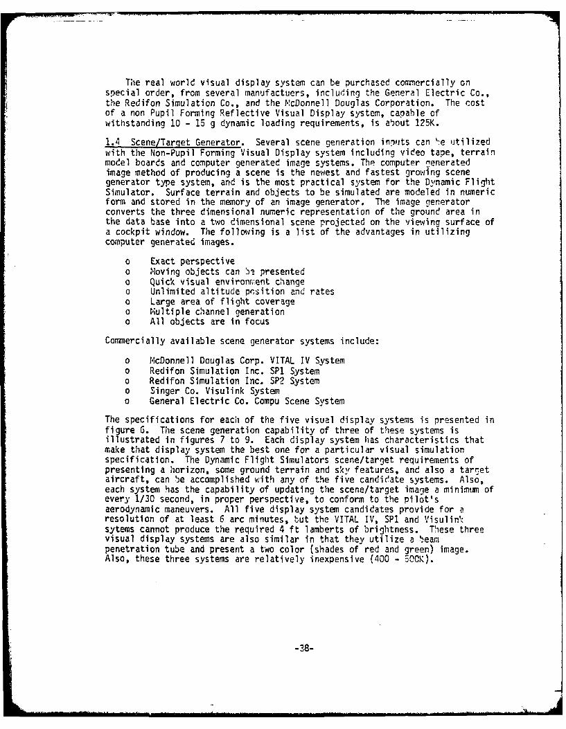
The real world visual display system can be purchased commercially onspecial order, from several manufactuers, including the General Electric Co.,the Redifon Simulation Co., and the McDonnell Douglas Corporation. The costof a non Pupil Forming Reflective Visual Display system, capable ofwithstanding 10 - 15 g dynamic loading requirements, is about 125K.
1.4 Scene/Target Generator. Several scene generation inputs can "e utilizedwith the Non-Pupil Forming Visual Display system including video tape, terrainmodel boards and computer generated image systems. The computer generatedimage method of producing a scene is the newest and fastest growing scenegenerator type system, and is the most practical system for the Dynamic FligitSimulator. Surface terrain and objects to be simulated are modeled in numericform and stored in the memory of an image generator. The image generatorconverts the three dimensional numeric representation of the ground area inthe data base into a two dimensional scene projected on the viewing surface ofa cockpit window. The following is a list of the advantages in utilizingcomputer generated images.
o Exact perspectiveo Moving objects can 5' presentedo Quick visual environrient changeo Unlimited altitude pcsition and rateso Large area of flight coverageo Multiple channel generationo All objects are in focus
Commercially available scene generator systems include:
o McDonnell Douglas Corp. VITAL IV Systemo Redifon Simulation Inc. SP1 Systemo Redifon Simulation Inc. SP2 Systemo Singer Co. Visulink Systemo General Electric Co. Compu Scene System
The specifications for each of the five visual display systems is presented infigure 6. The scene generation capability of three of these systems isillustrated in figures 7 to 9. Each display system has characteristics thatmake that display system the best one for a particular visual simulationspecification. The Dynamic Flight Simulators scene/target requirements ofpresenting a horizon, some ground terrain and sky features, and also a targetaircraft, can be accomplished with any of the five candir!ate systems. Also,each system has the capability of updating the scene/target image a minimum ofevery 1/30 second, in proper perspective, to conform to the pilot'saerodynamic maneuvers. All five display system candidates provide for aresolution of at least 6 arc minutes, but the VITAL IV, SPI and Visulin-sytems cannot produce the required 4 ft lamberts of brightness. These threevisual display systems are also similar in that they utilize a beampenetration tube and present a two color (shades of red and green) image.Also, these three systems are relatively inexpensive (400 - 500K).
i -38-

V '4'
000
VO A
lad- L.- Vb
J a 1 ~ 7 ' U.jZ-.5 '342.0- 0-j
().3 -_j____"
P 0 00CA
\D 11 . _ _ _ _ '4 _ _
1- M
3~ 0
0o_ _ _ _ _ ~ 0 _ _7_
-2 I
4..
(L '- X 0
Ot - N
5~' d,'LU a L'-,J11~
-J,.u.LZ
0 go w o O 9
_ _ _ _ _ 4g * _ _ _ _ _ (Z u \_ _ _
a_9

; , 4
NNW,LLL
-:4CLU
. 4,7
,:, 7 77
er
JL ;;S4
ob

IV.
z0
COl2
L4-
FI
6i 60
C'41

-4
L.
CL)0 -
'I C
C.
;-~*;At

The SP2 and Compu Scene systems meet all requirements including resolutionand brightness. In addition, they utilize a shadow mask tube and present athree color (shades of red, green, and blue) image. A basic SP2 system costsabout 65OK -while a basic Compu Scene system costs about 2500K. These systemscan be expanded to provide a more detailed real world image. The obvioustradeoff between the five system candidates is cost, display rightness,terrain detail and 2 vs 3 color presentation.
The real world visual display system and scene generation equipment w',illbe purchased with funding not detailed as part of the multipurpose dynamiccrewstation portion of the Dynamic Flight Simulator.
1.5 Computer Systems
The Dynamic Flight Simulator system .ill provide for the utilization ofthe 6600 Digital computer, EAI Analog Computer and the IDI Display Generatorcomputer systems, as described in Appendix A. No additional costs arerequired to provide the computer capability to handle the Dynamic FlightSimulator mission tasks; however depending upon the specific mission tasks,cockpit/computer interface equipment will have to be provided. These costswill be discussed in the next section of this memorandum.
1.6 Cockpit/Computer Interface
The cockpit/computer interface network, required for the Dynamic FlightSimulator, includes existing NAVAIRDEVCEN interface units, basically describedin Appendix A and specific Dynamic Flight Simulator interface units w.hich willdepend to some degree on the simulated aircraft and the mission task. TheSignal Distribution System, illustrated in Figure 4, must he weired to conformwith the Dynamic Flight Simulators requirements. A "3 BOX" interface unit isrequired to interface the equipment within the centrifuge gondola with thevarious computers, and their peripheral equipment. The gondola allows for thefollowing -airing complement through the systems slip rings.
NAVAIRDEVCEN CentrifugeTable 4 Gondola Slip Ring Wiring Complement
Section Quantity Current Ratina Volts AC Shieldin|
Physiological 15 1 amp. 250 Individual
Instrument and Control 48 5 amp. 250 Pairs
Instrument and Control 26 1 amp. 250 Pairs
15 amp. (Gondola)Power 16 35 amp. (Hub) 250
Coaxial 19 75 ohm. 250 Individual30 mc
Total 124
Obviously the gondola wiring lines are limited; so therefore an interfacewiring scheme is required that takes these limitations into account. Theproposed Dynamic Flight Simulator "J BOX" is integrated into the rear of thecockpit panel structure, as illustrated in Figure 10.
-43-

CO
14
-Z V
44

The cockpit panel structure is an exact replica of a F-14 aircraft, butthe interface wiring scheme is designed to accomodate any future flightsimulator program.
The "J BOX" wiring distribution, illustrated in Figure 11, consists of
four 20 pin coax amp connectors and twelve 56 pin Elco connectors.
o Tw-elve coax lines are utilized to drive cockpit displays
o Twelve shielded pairs (5 amp wire) are utilized for the outdiscreterequirements (24 maximum outdiscretes)
o Seven shielded pairs (1 amp wire) are utilized to provide a maximumof 63 indiscretes, coded as a binary word, with a differential circuit on eachwired pair. (One shieled pair is used as a control line). This indiscretewiring scheme requires the fabrication of an indiscrete interface encoder unitcosting about 15K
o Six shielded pairs (5 amp wire) are utilized to provide 20 inputpotentiometer signals and 10 output potentiometer signals. These signals willbe transferred serially across four of the shielded pairs, and two shieldedpairs are usec as control lines. This potentiometer signal -.irir:g schemerequires the fa'%rication of a potentiometer signal serial interface unit,costing ab'Cut 15K.
o Seven coax lines, six shielded pairs (I amp ,.ire) and six shieleedpairs (5 amp wire) remain to be used to drive the additional Dynamic FlightSimulator functions, such as the buffet assembly etc.
o Sixteen power lines are utilized to provide the necessary cockpitequipment power inputs. Eight 56 pin Elco connectors are used for the cockpitpower distribution interface. Twenty-eight Elco pins are jumpered together,on each connector, to provide the necessary number of input lines.
1.7 Problem Control Station. The basic equipment required for the DynamicFlight Simulator Program Problem Control Station, illustrated in reference 1,exists at NAVAIRDEVCER as an integral part of the complete centrifugefacility. Selected instrumentation, displays, switches, or indicators, willbe provided, as dictated by the specific Dynamic Flight Simulator mission tas'.
2.0 Software. The Dynamic Flight Simulator Software will be limited to aminimal amount of computer costs and software labor required to integrate,checkout, and demonstrate the basic multipurpose crewstation. The majority ofthe software required to drive the human centrifuge, cockpit instrumentation,displays, flight controls, etc., will have to be provided by a specificprogram.
-45-

IWTRUONT ; FL4rT (ON7rft.L*
PUR. PUR. 4
WX("POT. POTrI 06, o 1. 5 1(7
8 (AX20 10
55424 (194IDSOUT 9J
i~iAL
+15/ -S/100V
145Li.
A6~ $PAE 1j0 115V 1115v 115v 1
FIGURE 11 Dynamic Flight Simulator"IJ BOX" Wiring Schemie
46

IV Crewstation Simulation Development Effort
1. Work Breakdown Structure
The Work, Breakdown Structure for the design and eevelopment of the DynamicFlight Simulator is presented in figure 12. The multipurpose crewstationlabor breakdown (man-months) portion of the Work Breakdown Structure ispresented in table 5.
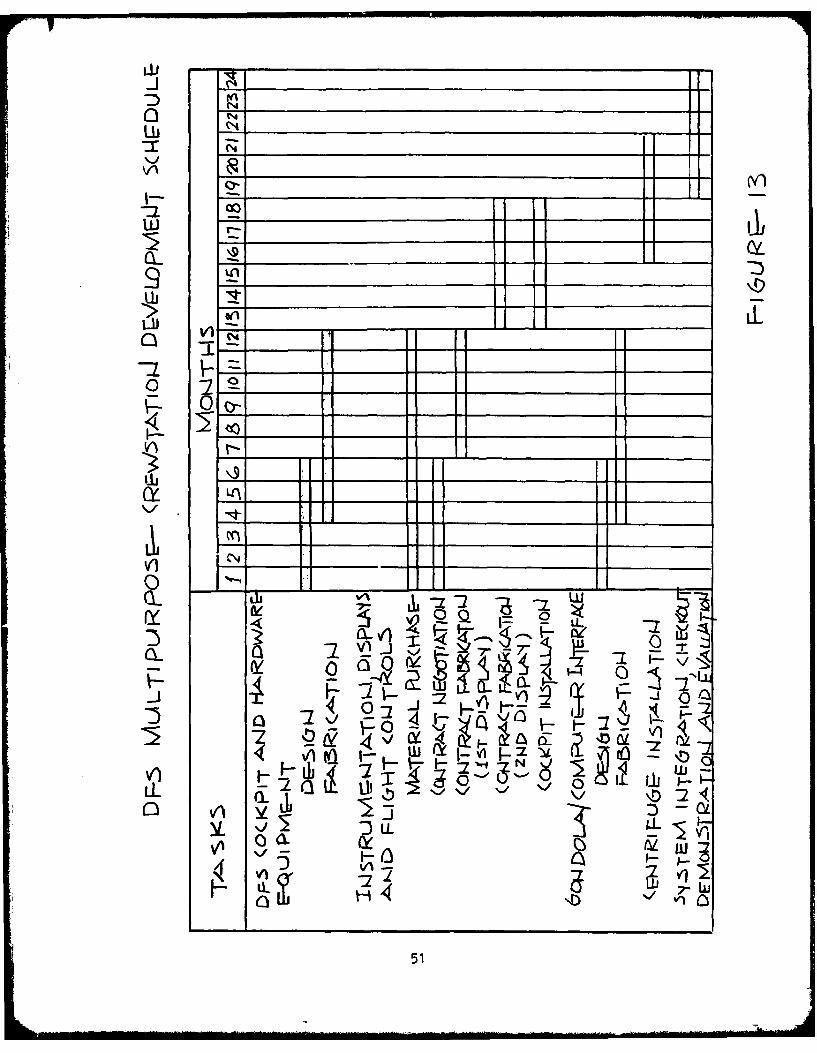
2. Schedule
The design and development schedule, as illustrated in figure 13, requiresa two year period for completion. This schedule is dictated by the availablefunding.
-47-

LL
~LV-
LIU V0
$i~~4L w 7:2
ILL

Table 5 Multipurpose Crewstation Labor Work Break<dow,.n 1,/12'-
Labor Break down(man months)
W1.0 Software Development 4.0W1.1 Gondola Drive 0.0W1.2 Cockpit Displays 0.0W1.3 Instrumentation 0.0W1.4 Real World Visual Display-Systemn 0.0W1.5 System Integration and Checkout ?.
W2.0 Hardware Development 48.0W2.1 Gondola (Mechanical Hardware) ?0. S
1,2.1.1 F-14 Cockpit and Buffet System 18.0WZ2.1.1.1 Design (E) 5.75W2.1.1.2 Material Acquisition CE) .25W2.1.1.3 Fabrication (T) 10.0W2.1.1.4 Contract Negotiation CE) 0W2.1.1.5 Contract Fab Liaison (E) 0W2.1.1.5 Installation (T) 2.0
W2.1.2 Flight Controls ?.0W2.1.2.1 Design CE) .75W2.1.2.2 Material Acquisition CE) .25W2.1.2.3 Fabrication CT) 1.5W2.1.2.4 Contract Negotiation CE) 0W2.1.2.5 Contract Fab Liaison (E) 0W2.1.2.6 Installation CT) E5
U2.1.3 Instrumentation and Displays 2.0W2.1.3.1 Design (E) .5W2.1.3.2 Material Acquisition (E) 0*W2.1.3.3 Fabrication CT) 1.0W2.1.3.4 Contract Negotiation (E) .25W2.1.3.5 Contract Fab Liaison (E) .25W2.1.3.6 Installation CT) 0
W2.1.4 Panels, Switches and Indicators "..5W2.1.4.1 Design CE) 1.25W2.1.4.2 Material Acquisition (E) .25W2.1.4.3 Fabrication CT) 3.0W2.1.4.4 Contract Negotiation CE) 0W2.1.4.5 Contract Fab Liaison CE) 0W2.1.4.6 Installation (T) 0
W2.1.5 Real Work Display System Installation 3.0W2.1.5.1 Design CE) 1.0W2.1.5.2 Material Acquisition CE) 0W2.1.5.3 Fabrication CT) 1.5W2.1.5.4 Contract Negotiation (E) 0W2.1.5.5 Contract Fab Liaison (E) CW2.1.5.6 Installation (T)
-49-

Labor Breakdown(man months)
W2.2 Gondola (Electrical Hardware) 4.5W2.2.1 Flight Controls Instrumentation,
Displays, Panels, Switches,Indicators, Buffet SystemCommunications, Etc. 4.5(Wiring & Cabling)
W2.2.1.1 Design (E) 1.25W2.2.1.2 Material Acquisition (E) .25W2.2.1.3 Fabrication (T) 2.5W2.2.1.4 Contract Negotiation (E) 0W2.2.1.5 Contract Fab Liaison (E) 0W2.2.1.6 Installation (T) .5
W2.3 Gondola/Computer Interface - (Mechanicaland Electrical Hardware) 10.0W2.3.1 Signal Distribution System, Cockpit
"J" Box, Indiscrete Encoder, Pot.Signal Serial Interface 10.0
W2.3.1.1 Design (E) 4.5W2.3.1.2 Material Acquisition (E) .5W2.3.1.3 Fabrication (T) 5.0W2.3.1.4 Contract Negotiation (E) 0W2.3.1.5 Contract Fab Liaison (E) 0W2.3.1.6 Installation (T) 0
W2.4 Real World Visual Display SystemW2.4.1 Visual Display 0W2.4.1.1 Design (E) 0W2.4.1.2 Material Acquisition (E) 0W2.4.1.3 Fabrication (T) 0W2.4.1.4 Contract Negotiation (E) 0W2.4.1.5 Contract Fab Liaison (E) 0W2.4.1.6 Installation (T) 0
W2.4.2 Scene Generation SystemW2.4.2.1 Design (E) 0W2.4.2.2 Material Acquisition (E) 0W2.4.2.3 Fabrication (T) CW2.4.2.4 Contract Negotiation (E) 0W2.4.2.5 Contract Fab Liaison (E) 0W2.4.2.6 Installation (T) 0
W2.5 System Integration and Checkout .0 2.0W2.5.1 Cockpit System (E&T) 3.0W2.5.2 Real World Display Systems (E&T) 0
-50-
0 N
Lb '
04
a a
' 0 d 0 t-4 4a
w vi
vi I- O:51

V. Resources
1. 'AVAIRDEVCEN Manpower Requirements
Development
W1 Software (W1.1 - W1.5)Inhouse LaborEngineering 9.0 Man Mo.Shop/Tech 0.0 Man Mo.
Su Total 4.0 Man Mo.
W2 Hardware (W2.1 - W2.5)Inhouse La!)orEngineering 18.5 Man t-o.Shop/Tech 2.5 Man Mo.
Sub Total 48.0 *an To.Development Total 52.0 Man Mo.
The total estimates of the Dynamic Flight Simulator Program manpowerrequirements over the next two years are about
FYSO (Development 2.7 Man Yrs.FY81 (Development and Demonstration) 1.5 Man Yrs.
-52-

2. Facilities
Development
W1 Software
The software facilities include periodic use of the rAVAIRDEVCEN 6600computer "A" system for debug and "B" System for integration/validation.
W2 Hardware
The centrifuge gondola is required periodically over a E month period forinstallation, integration and checkout of the Dynamic Flight Simulatorequipment.
3. Contracts
Development
W Software
None
W2 Hardware
Cockpit Display System FOK(2 required)
-53-

VI Costs
W Software (WI.1 - W1.5)
Inhouse Labor
Engineering (4 man months) (5K/mo) = 20.OKShop/Tech (0 man months) (4.2K/mo) x 0Materials/Computer 10Contracts 0
Sub Total
W2 Hardware (W2.1 - W2.5)
Inhouse Labor
Engineering (18.5 man months) (5K/mo) = 102.5KShop/Tech (29.5 man months) (4.2K/mo) = 124Materi al s/Cornputer 45Contracts 60
Sub TotalDynamic Flight Simulator DevelopmentCost Total 351.5K
-4
-54-

VII References
(a) General Description and Performance characteristics of the HumanCentrifuge by W.D. Day~mon, Crew System Department, NAVAIRDEVCEJ, January 175
(b) High Acceleration Cockpit Program Visual Display System Study by G.Terry Thomas and John S. Mudryk, Technical Memorandum 78-HAC-O01
(c) NAVAIRDEVCEN F-14 Spin Simulation Program Proposal Report Softvware
and Comnter Directorate, Aircraft and Crew Systems Technology DirectorateSept-

APPENDIX A
A DYN4AMIC FLIGHT SINULATOR CENTRIFUGE
I. DYNAMIC FLIGHT SIULATOR
The NAVAIRDEVCEri I:uman Centrifuge, illustrated in Figure 1t, is one of theworld's larget and most versatile centrifuges. In a climate of largeamplitude six degrees- of-freedom dynamic flight simulators, it is the onlydevice capable of simulating, under pilot control, the rapidly applied andsustained G profiles (including buffet) associated with air combat maneuvers;or the multi- directional complex G profiles associated with out-of-controlflights such as spin.
Additionally, the centrifuge can simulate the near vacuum condition of125,000 ft altitude, dual-axis vibration from zero to 25 hg., ambienttemperature changes form 40 degrees F, sound levels to 130 eeciles, andflight levels from complete darkness to extreme brightness. Thesecapabilities are providing the scientists and en-ineers of the Aircraft andCrew Systems Technology Directorate a very unique tool for investigating theeffects of each of the individual stresses of acceleration, vibration,altitude, temperature, sound, light, and disorientation on pilot performancecombined in an environment such as the real world combines stresses.
Actual and simulated cockpits of the F-4, F-14, and A-7 aircraft have beeninserted in the 10 ft sphericai gondola with all controls and displaysactivated through a local analog computer. Studies have been performed todetermine man's psychological response to the realistic stress environment ofa fighter pilot.
Those studies include an evaluation of the type and location of variousemergency activation devices, the dynamic verification of a number of controlsand displays, and the dynamic testing of various personnel protection and lifesupport equipment.
Planned improvements to the simulator include an expansion of its currentanalog computer system to include both digital and hybrid computercapabilities in order to provide more complex coclpit displays and controlsfor the simulator pilot and to provide the capability of simulating morecomplex aircraft, such as the F14, F15, F16, F1S and future high performanceaircraft.
-56-

-064
A~4o

2 DYNAMIC FLIGHT SIMULATOR COMPUTER FACILITY
2.1 NAVAIRDEVCEN'S CDC 6600 COMPUTER
The 6600 computer system pictured in Figure 15 is a CDC E600 series hybridcomputer system which was developed for the Naval Air Development Center andis specifically tailored to NAVAIRDEVCEN's requirements. The system providesthe capability of simultaneously processing various real-time simulationprograms concurrently with the processing of batch jobs, multiple usercommunication with the computer system in a conversation mode via terminals,graphics, and automatic test-data acquisition and processing.
The system consists of two CDC 6600 central processing units (CPUt), tenperipheral and control processors and a complement of peripheral equipment,most of which can be shared between the computers. This results in aninteresting and unique configuration in that the central processor is anextremely high-speed arithmetic processor which communicates only with centralmemory while the smaller, slower peripheral and control processors communicatewith both central memory and the peripheral devices. This permits the centralprocessor to continue high-speed computations while the peripheral and controlprocessors do the slowe I/O and supervisory operations.
The real-time requirements are satisfied by two hardware real-timemonitors (one per CPU), which initiate real-time operation in response to aninterrupt using the least-time-to-go algorithm, four direct analog/discreteinput/output systems (DADIOS) which send and receive data from rIAVAIRDEVCEN'sreal time equipment and a read-write bus adaptor to interface between theDADIOS and HRTM and central memory.
-58-

- - a)
-l
-4
-4
C-)
~ -4'-4-4.~ -4>0
-4
C:)
I-'CL.
IL
~N. ~t

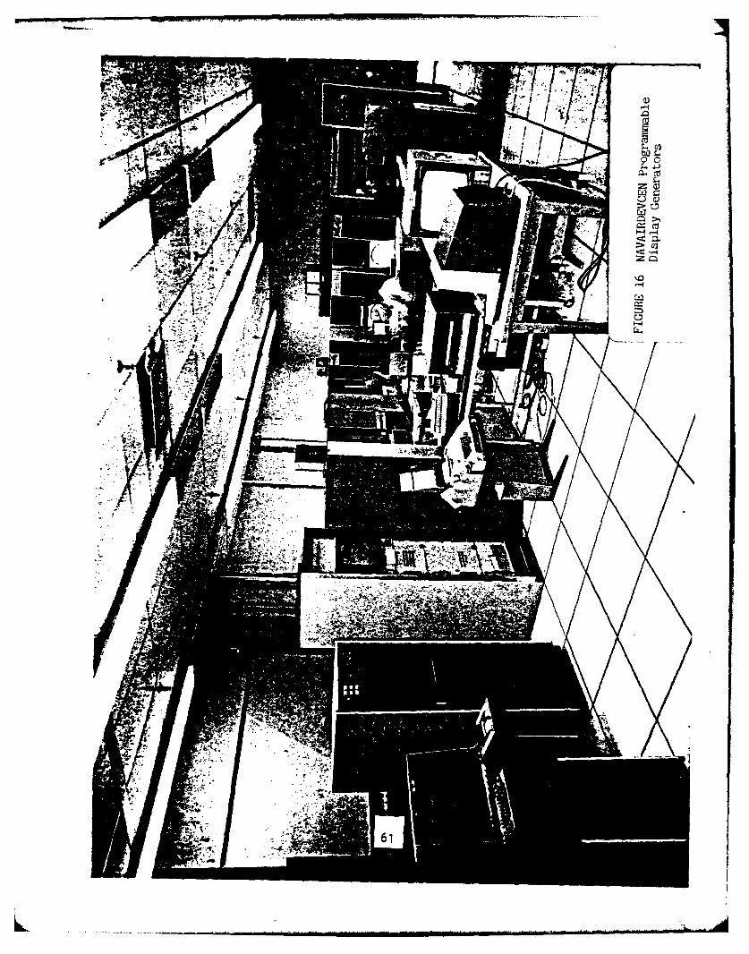
2.2 PROGRA eIABLE DISPLAY GEJERATORS
The m:.:r portion of the display work is performer Ny three PDP-3mini-computers and two IDIOM I computers, pictured in Figure 1C. The PDP-Zis a high speed, general purpose digital computer which operates on 12-'itbinary numbers and has a cycle time of 1.5 microseconds. It is a singleaddress parallel machine that uses two's complement arithmetic. The PDP-8 issupported by a comprehensive set of operating system software -hich allows theuser to efficiently program his applications. Also containee in this computeris the 338 Programmed Buffered Display which is a display subsystem thatcontrols a CRT. Up to eight CRTs may be remotely slaved to the 338 Display,and they may receive identical or different information depending on certaindisplay file instructions.
The PDP-8 is usally driven by the 6600 computer using an interruptprocedure. An I/O routine is called to direct or control the reading of datainto storage in the POP-S. The data consists of positional coordinates,alphanumerics, verctor lengths, and symbol flag words that specify the itemsthat are to be displayed. This data may be used to present flight informationto a pilot in a cockpit, acoustical information to a sensor operator, ortabular information.
The two IDIOrM II computers are the most recent additions to the simulationcomputer facility. The IDIOM is a 16 bit machine 1ith approximately ten timesthe display capabilities of the PDP-8s.
-60-
Z0
'-4-
2.3 ELECTRONIC ASSOCIATES. INC. ANALOG COWPUTER
The Electronic System Simulator (ESS), pictured in Figure 17, is a soliestate, 100 volt reference analog machine with parallel digital logic. Theanalog and digital components are programmable through analog and digitalpatchboards. Each hybrid/analog machine is connected to the real-time digitalsystem via trunking to the A/D units and D/A units. Other trunks areterminated at the various simulation mock-ups.
In general, the hybrid/analog machine is used in the modeling of aircraftcontrol systems to take advantage of its continuous solutions of complextransfer functions. Five of the devices are located in the computersimulation Facility of the Systems Analysis and Engineering Department.
-62-

4.A
& ..y,
;~\;4 -

DYNAMIC FLIGHT SIMULATOR CENTRIFUGE/COMPUTER INTERFACE
NAVAIRDEVCEN is currently engaged in linking the central computer systemto the Dynamic Flight Simulator (centrifuge). This effort will he completed 1October 1C79. The program consists of three major elements.
The first is the acquisition of a display and data collection computer.The second is the development of fiber optic digital-to-digital link andthird, the laying of high-quality video and analog transmission lines. Figure18 shows the three computers and devices in the link.
A detailed description of the major elements follows.
DISPLAY/DATA ACQUISITION COMPUTER
0 PROCESSOR- Varian (Sperry) V77 Mini-Computer
64K - Words of 660 Nano-Sec Dual Port ,;EMIORYHardware Floating Point ProcessorVortex-Real Time Operating System
1. Handles Display Program Generation and Updates2. Performs Real Time Data Acquisition and Handling Task s
FIBER OPTIC DATA LINK
FUNCTION
High Speed Data Transfer Between CDC 6600 Simulation Computer andDisplay/Data Acquisition Computer
DATA TRANSFER CHARACTERISTICS
o Data Transferred 0 5 Million bits per second(faster than CDC 6631 channel)
o Data Transferred in 256 x 16 bit blockso Total Data Transmission Time for 1 block = 2.1 milliseconds
CABLE TIE IN
- Fiber Optic Cable (Galite 5000D-73) - 2 cableso For High Speed Digital
- 24 Coax Cable with External Guard Shieldo For Single Ended Signals
- 54 Twisted Pairs Each with Foil Shieldo For Differential Analog Signals.
- High Quality Double Shielded Twisted Pair Cable - 8 cableso Primarily for Differential Video Signals

LbN
Lii
4.- v.
.-. .'-
7Z CieL dj
4 A)
la 2
:3-
-J
65h