Embed Size (px)
Citation preview
ADAPTABILITY OF A GRAPHIC SYSTEM PROCESSOR TO
THE GRAPHICAL KERNEL SYSTEM
by
KALAR S. RAJENDIRAN, B.E.
A THESIS
IN
COMPUTER SCIENCE
Submitted to the Graduate Faculty of Texas Tech University in
Partial Fulfillment of the Requirements for
the Degree of
MASTER OF SCIENCE
Approved
Accepted
August, 1988
1 i
/ -o.'l^ C op' ^
ACKNOWLEDGEMENTS
I am deeply indebted to Dr. Mieheal Parten for his
guidance and support throughout this thesis. I am also
grateful to Dr. William Marey and Dr. Donald Gustafson for
serving on my committee and providing useful suggestions.
I would like to thank Texas Instruments Incorporated for
funding the project.
I would also like to thank my family and friends
for their love and encouragement, which enabled me to
undertake and complete my Master's Degree.
11
CONTENTS
ACKNOWLEDGEMENTS ii
LIST OF FIGURES vii
CHAPTER
I. NEED FOR A GRAPHICS STANDARD 1
II. GRAPHICAL KERNEL SYSTEM 3
Introduction 3
GKS Levels of Functionality 4
Generation of Application-Oriented
Subsets 4
Implementation Feasibility 4
Upward-Compatibility 5
Workstations 5
Coordinate Systems and Transformations 5
Coordinate Systems 5
Transformations 7
Windows and Viewports 7
Output 8
Output Primitives 8 Attribute Specifications 8
Segments 8
111
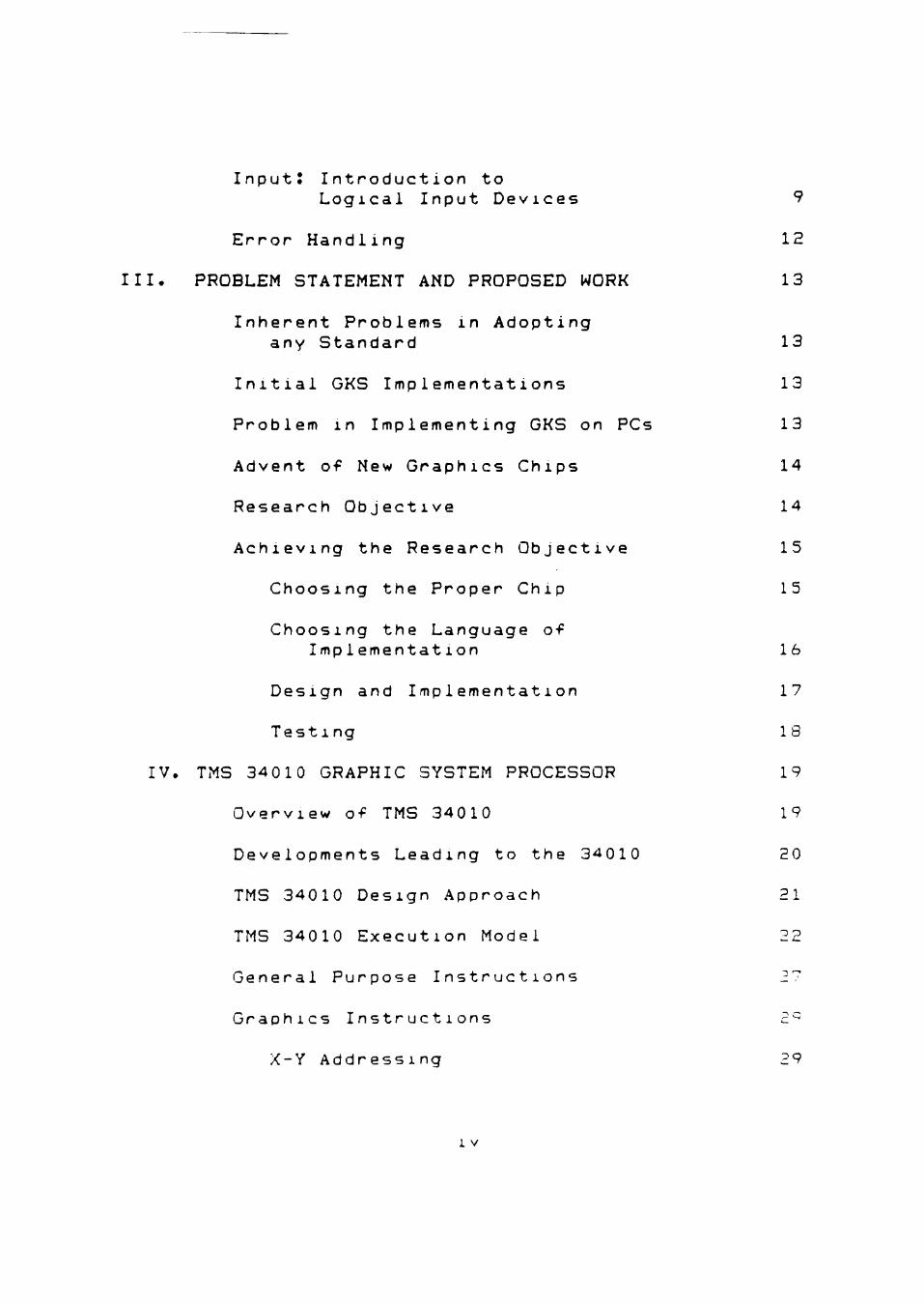
InputJ Introduction to
Logical Input Devices 9
Error Handling 12
III. PROBLEM STATEMENT AND PROPOSED WORK 13
Inherent Problems in Adopting
any Standard 13
Initial GKS Implementations 13
Problem in Implementing GKS on PCs 13
Advent of New Graphics Chips 14
Research Objective 14
Achieving the Research Objective 15
Choosing the Proper Chip 15
Choosing the Language of
Implementation 16
Design and Implementation 17
Testing 18
IV. TMS 34010 GRAPHIC SYSTEM PROCESSOR 19
Overview of TMS 34010 19
Developments Leading to the 34010 20
TMS 34010 Design Approach 21
TMS 34010 Execution Model 22
General Purpose Instructions 27
Graphics Instructions 2^
X-Y Addressing 29
1 V
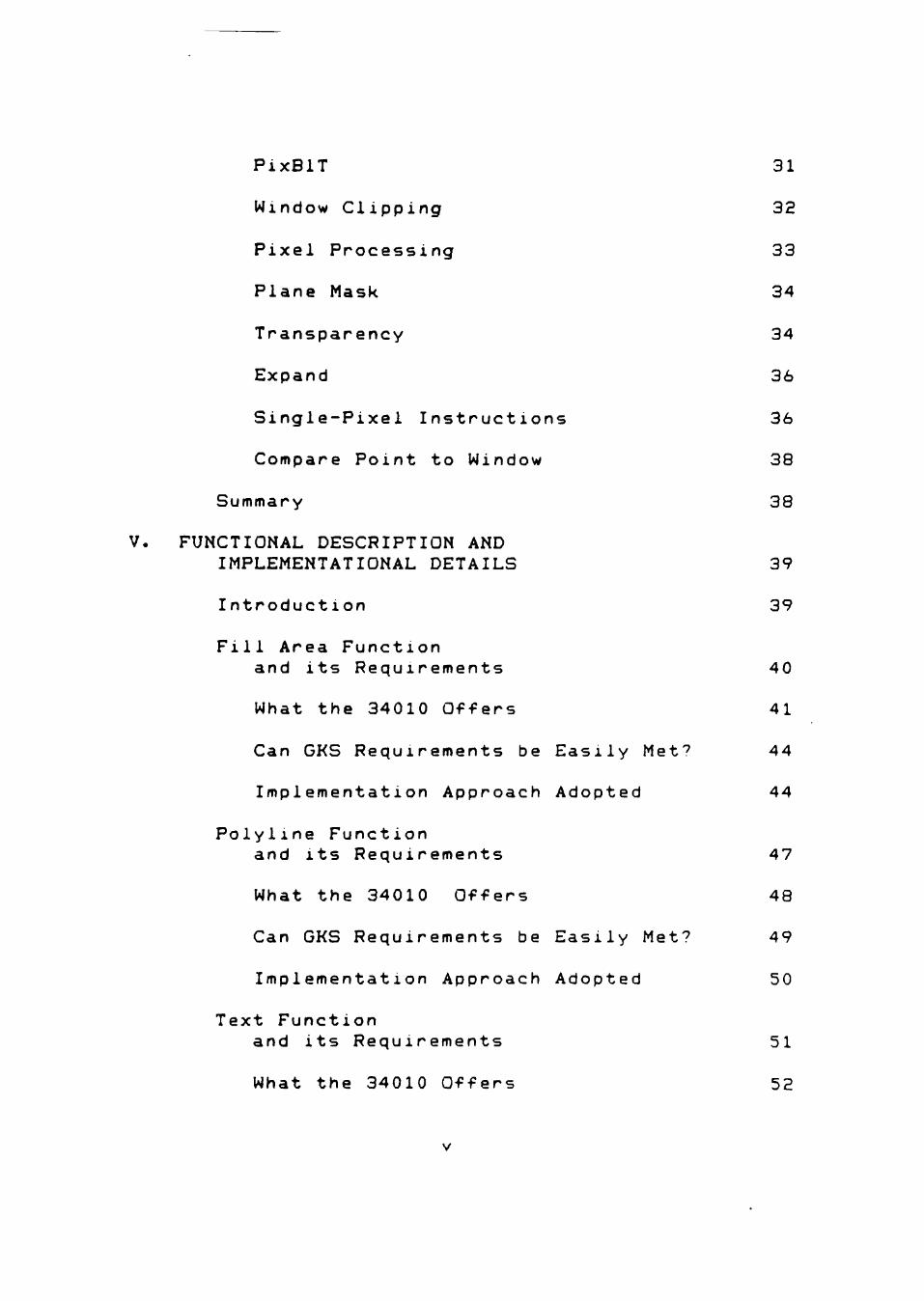
PixBlT 31
Window Clipping 32
Pixel Processing 33
Plane Mask 34
Transparency 34
Expand 36
Single-Pixel Instructions 36
Compare Point to Window 38
Summary 38
V. FUNCTIONAL DESCRIPTION AND
IMPLEMENTATIONAL DETAILS 39
Introduction 39
Fill Area Function
and its Requirements 40
What the 34010 Offers 41
Can GKS Requirements be Easily M e f 44
Implementation Approach Adopted 44 Polyline Function
and its Requirements 47
What the 34010 Offers 48
Can GKS Requirements be Easily Met? 49
Implementation Approach Adopted 50
Text Function
and its Requirements 51 What the 34010 Offers 52
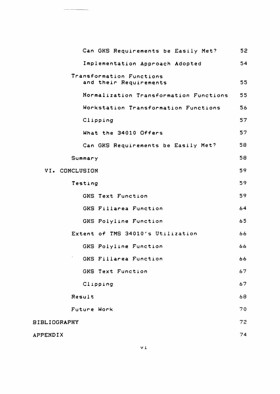
Can GKS Requirements be Easily M e f 52
Implementation Approach Adopted 54
Transformation Functions
and their Requirements 55
Normalization Transformation Functions 55
Workstation Transformation Functions 56
Clipping 57
What the 34010 Offers 57
Can GKS Requirements be Easily Met? 58
Summary 58
VI. CONCLUSION 59
Testing 59
GKS Text Function 59
GKS Filiarea Function 64
GKS Polyline Function 65
Extent of TMS 34010's Utilization 66
GKS Polyline Function 66
GKS Filiarea Function 66
GKS Text Function 67
Clipping 67
Result 68
Future Work 70
BIBLIOGRAPHY 72
APPENDIX 74
V 1
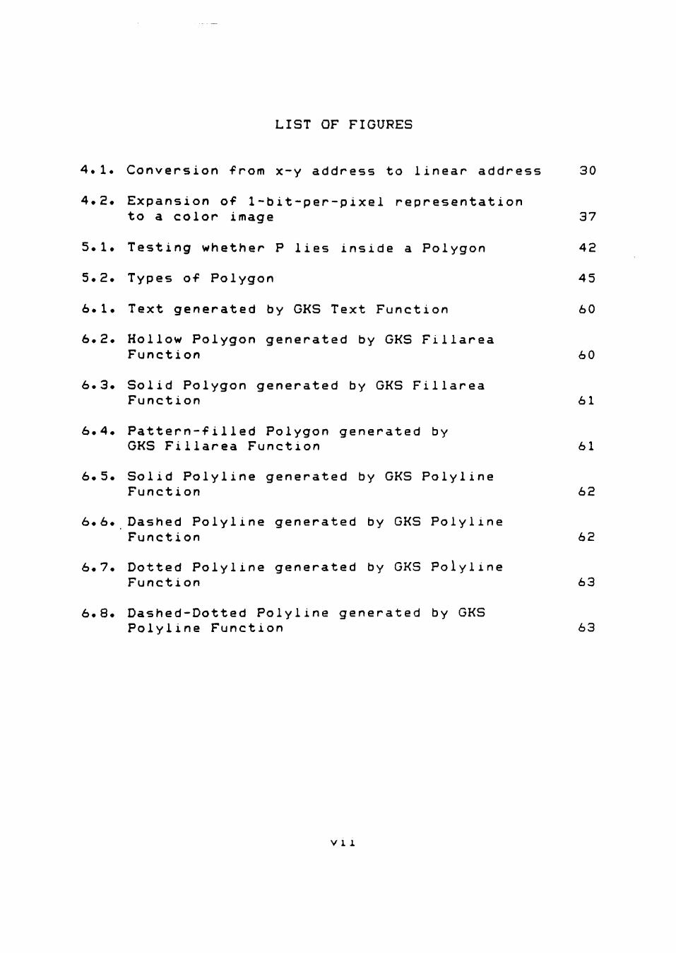
LIST OF FIGURES
4.1. Conversion from x-y address to linear address 30
4.2. Expansion of 1-bit-per-pixel representation to a color image 37
5.1. Testing whether P lies inside a Polygon 42
5.2. Types of Polygon 45
6.1. Text generated by GKS Text Function 60
6.2. Hollow Polygon generated by GKS Filiarea Function 60
6.3. Solid Polygon generated by GKS Filiarea Function 61
6.4. Pattern-filled Polygon generated by GKS Filiarea Function 61
6.5. Solid Polyline generated by GKS Polyline Function 62
6.6. Dashed Polyline generated by GKS Polyline Function 62
6.7. Dotted Polyline generated by GKS Polyline Function 63
6.8. Dashed-Dotted Polyline generated by GKS Polyline Function 63
v 1 1
CHAPTER I
NEED FOR A GRAPHICS STANDARD
The old proverb "a picture is worth a thousand words"
is as true for computer systems as for other media.
Naturally, computer graphics is the most versatile and
most powerful means of communication between a computer
and a human being. Hence, the fact that the origins of
computer graphics can be traced back almost to the advent
of digital computers should not come as a surprise to
anyone. Since then, graphics hardware technology has
evolved rapidly with time, producing better and better
graphics devices. As each new device hit the market, many
different graphics application software packages were
written by different software vendors to exploit the
special features of each device. Many of these software
packages would work only on one computer system. The
source of incompatibility was in-line graphics calls to
system-dependent functions. This approach resulted in
application software that was difficult* if not
impossible, to transport to other computers. This
underlined the urgent and compelling need - or a
universally accepted, hardware-independent graphics
standard.
Basically, the standard was to provide the general
graphics capabilities required by application programs
through standard functions with a fixed number of
parameters. Each computer graphics system was expected to
make these standard graphics functions available to
application programs. The use of system-dependent graphics
function calls was to be restricted to within these
standard graphics functions. The application programmer
could then concentrate on his specific problem without
having to develop graphics capabilities as well. The
strongest single justification for the development of a
standard was the promotion of program portability.
However, programmer portability, that is, the ability of
an application programmer to move from one installation to
another with minimal retraining, was another strong point
in favor of a standard.
CHAPTER II
GRAPHICAL KERNEL SYSTEM
Introduction
The Graphical Kernel System (GKS), which is the
subject of this chapter, covers the most significant parts
of computer graphics. The Graphical Kernel System is the
first international standard for programming computer
graphics applications. It offers functions for picture
generation, picture presentation, segmentation,
transformations and input. However, the extent of the
functional capabilities is not the only important aspect
of the standardization of the Graphical Kernel System.
There is an even more important advantage of the GKS
standardization.
For the first time, a methodological framework for
the various concepts within the field of computer graphics
has been developed. This is the base for a common
understanding and a common terminology for creating
computer graphics systems, for using computer graphics,
for talking about computer graphics and for educating
students in computer graphics methods, concepts and
app1icati ons.
GKS Levels of Functionalitv
GKS, as a general-purpose graphical kernel system, is
designed to address most of the existing graphics devices
as well as most graphics applications. GKS systems have to
be installed on various processors with different
qualities like restricted memory sizes, slow external
storage media, and virtual memory management.
Obviously, it is not sensible to use one fixed GKS
system for all the different purposes. Rather, it is
desirable to tailor GKS to the special qualities of the
specific environments existing at each time. An important
means for adapting a GKS system to achieve the above
mentioned goal is provided by the definition of suitable
subsystems, called levels.
Generation of Application-Oriented
Subsets
For every representative set of application classes,
a suitable subset of graphics functions was selected?
thus, no extra burden in acquiring, installing, learning,
memorizing, and handling unnecessary functions is placed
upon the system and application programmers.
Implementation Feasibility
The capabilities of the overall GKS are distributed
among the levels in such a way that subsystems of
considerably smaller program sizes can be implemented.
This is accomplished by isolating specific concepts and
assigning them to the single levels. Thus, concepts can be
integrated or omitted as a whole. This decreases
compilation, linkage editor, and program performance time
and supports the usage of small memory machines.
Upward-Compatibility
All GKS functions are defined to have identical
effects on all levels in which they exist. Regardless of
which GKS level an application program is written for, it
will run on every higher level achieving the same results.
Workstations
GKS develops the concept of a workstation which, in
its simplest form, is a single display area that may or
may not have input capabilities. An application program
may be concurrently connected to one or more workstations,
with the graphics it produces displayed on all active
workstations. The application program may also dynamically
open and close workstations.
Coordinate Systems and Transformations
Coordinate Systems
It IS common practice for an application programmer
to define his graphical elements in a coordinate system
that is related to his application. Output devices that
are used for presenting the visual image of the elements,
however, normally require the use of a device specific
coordinate system. In order to meet these requirements
while maintaining device independence, three coordinate
systems (WC, NDC, and DC) have been defined in GKS as
explained below. The application programmer uses the world
coordinate <WC) system for specifying picture elements.
The world coordinate system is the standard user
coordinate system. Conceptually, every output primitive is
defined with its own world coordinate system.
Since different output devices have different device
coordinate systems, GKS defines, as an abstraction of
these device coordinate systems, one single normalized
device coordinate (NDC) space. The relative positioning of
output primitives is defined by mapping all the defined
world coordinate systems onto the NDC space.
Although NDC space conceptually extends to infinity,
the part of NDC space in which the viewport must be
located and that can be viewed at a workstation is the
closed range CO,l]xCO,l]. The normalized picture in NDC
space can be stored and manipulated via the segment
mechan i sm.
The NDC space is mapped onto the device coordinates
(DC) of every workstation that is to display the picture.
Every type of workstation may have a different device
coordinate space and a different mapping. The device
coordinate space is always a bounded space since it
represents the extension of the display surface of a
physical, and hence bounded, device.
Transformations
A transformation that defines the mapping from the
world coordinate system onto the single NDC space is
re-ferred to as a normalization transformation. A
transformation that defines the mapping of NDC space to
any one of the active workstations is re-ferred to as a
workstation transformation. Other types of trans
formations can be applied to segments and take place in
the NDC space.
Wi ndows and Vi ewports
In GKS, the rectangular portion of a plane that
coordinates come from is called a window, and the
rectangular portion of a plane that coordinates map into
IS called the viewport.
Through the use of windows and viewports, GKS can
select different portions of the virtual picture and
8
display it in a specified portion of each workstation
display surface. The viewport for a device is expressed in
device coordinates.
Output
Output Primitives
Output primitives are the functions used to construct
graphic images (e.g., draw a line, fill a polygon, draw
text, etc.).
Attribute Specifications
This is the ability to specify how various primitives
will appear (e.g., a line can be drawn with different
styles, color, and width). Furthermore, GKS defines a
conceptual model for specifying attributes, called
bundling.
Segments
GKS provides a way to collect and store the
primitives that make up all or part of a picture. Such a
collection of primitives is called a "segment," which is a
group of graphic output primitives identified by a unique
name. Segments may be made visible or invisible,
highlighted, deleted, renamed, transformed, assigned a
priority and made detectable or undetectable.
Input: Introduction to Logical Input Devices
An application program using a GKS implementation
obtains graphical input from an operator by controlling
logical input devices which deliver logical input values
to the program. If, for instance, a position is required
in an application program, a "LOCATOR" device is to be
selected (instead of a physical cursor device). If a
character string is required, the logical device "STRING"
has to be used (instead of a physical keyboard). Whereas
the application program can control the available logical
input devices, the mapping o-f logical to physical devices
is done by the implementation.
Log ical Input CI asses and Values
GKS provides six logical input classes namely
LOCATOR, STROKE, VALUATOR, CHOICE, PICK, and STRING. Each
input class determines the type of logical input value
that the logical input device delivers. The six input
classes and the logical input values they provide are as
foilows.
Locator
A position in world coordinates (a pair ot REAL
numoers) and a normalization transformation number.
10
stroke
A sequence of positions in world coordinates and a
normalization transformation number.
Valuator
A REAL number.
Choice
A non-negative INTEGER value which represents a
selection from a number of choices. A zero indicates "no
choice. "
Pick
A PICK status (OK,NOPICK), a segment name and a pick
identifier. Primitives outside segments cannot be picked.
String
A string of CHARACTERS.
Openating Modes
Each logical input device can be operated in tnrae
modes, called operating modes. At any time, it is in one f
and only one, oi^ the modes set by the invocation of a
function in the group SET <input class) MODE. The tnrqo
operating modes are REQUEST, SAMPLE and EVENT. Input f'-om
devices is obtained in different ways depending on the
mode.
11
Request
A specific invocation of REQUEST <input class)
causes an attempt to read a logical input value from a
specified logical input device, which must be in REQUEST
mode. GKS waits until the input is entered by the operator
or a break action is performed by the operator. The break
action IS dependent on the logical input device and on the
implementation. If the break occurs, the logical input
value IS not valid.
Samp 1e
A specific invocation of SAMPLE (input class) causes
GKS (without waiting for an operator action) to return the
current logical input value o-f a specified logical device,
which must be in SAMPLE mode.
Event
GKS maintains one input queue containing temporally
ordered event reports. An event report contains the
identification of a logical input aevice and a logical
input value from that device. Event reports are generated
asynchronously, by operator action only, from input
devices in EVENT mode.
The application program can remove the oiaest event
report from the queue, and examine its contents. The
12
application can also flush all event reports of a
specified logical device from the queue.
Error Handling
GKS has a well defined set of errors which will be
reported back to the application program. The philosophy
adopted is that all errors are reported by putting details
of the error in the error file which was specified when
GKS was opened. A typical error will record the following
i nformation.
1) An error number indicating which error has
occurred.
2) The name o-f the GKS function that was being
executed when the error was detected.
There is a full set o-f error numbers so that a
particular error can be precisely identified. What happens
when an error has been recognized depends on the
application program. If no special action has been
specified, GKS calls the installation supplied error
handling procedure.
CHAPTER III
PROBLEM STATEMENT AND PROPOSED WORK
Inherent Problems in Adopting any Standard
When standard interfaces are written into software,
they are implemented with complex algorithms that execute
slowly, resulting in performance loss C8]. Graphics
standard interfaces are no exception to this. But the
effect of performance loss is accenuated in the case o-f
graphics. This is very often the reason software vendors
bypass standards in order to gain better performance.
Initial GKS Implementations
Initial implementations of GKS were designed to run
on main-frames and mi n i-computer s because o-f their fast
floating-point hardware, high processor cycle times, large
memory (or at least virtual memory system), etc. With
personal computers becoming more popular and memory costs
beginning to drop, the implementation of GKS on PCs is
becoming desirable.
Prob1 em 1n Imp 1emen11ng GKS on PCs
The processors powering most o-f the personal
computers do not support any special graphics
instructions. This makes it necessary to implement certain
graphics functions using complex algorithms. Conseaupntlv.
13
14
the code of a graphics system on these processors becomes
large and inefficient. If the graphics system were
implemented using GKS specifications, the system would
become even more inefficient due to the more general
nature and additional functions needed in the code.
Implementing GKS on a PC has not seemed very attractive.
Advent of New Graphics Chips
Texas Instruments, Intel, and Advanced Micro Devices
have recently developed new graphics chips. The companies
claim that their chips will improve the graphics
performance of personal computers tremendously. These new
graphics processor chips may allow an efficient GKS
implementation on a PC.
Research Obi ective
Graphical Kernel System (GKS) was defined before
graphics processors became available for PCs. The research
objective is to determine if GKS is a viable standard for
the TMS 34010 Graphic System Processor (available for
PCs), by implementing portions of GKS on it and
determining if the implementation makes use of the power
of the graphics processor.
15
Achieving the Research Objective
Choosing the Proper Chip
The TMS34010 Graphic System Processor was chosen for
our GKS implementation based on the following criteria.
a) The first and most important requirement is the
compatibility of the chip being chosen, with the family of
most popular personal computer models (IBM PC and its
clones). The TMS34010 GSP can easily be interfaced to the
TI PCs, IBM PCs and its compatibles.
b) The GSP chip is a general-purpose processor chip
with special graphics capabilities in contrast to the
chips from other manufacturers.
e) Graphics operations require the manipulation of
many variables during the drawing process and the
availability of many general purpose registers enhances
the speed of operation by reducing time-consuming data
swapping between memory and registers. The TMS34010 GSP
has a total of 31 32-bit registers.
d) The horizontal and vertical timing of a raster
display system is usually fixed. So the sweeper must
provide new data at precise intervals. For this reason,
the sweeper is given priority access to the frame buffer.
On high resolution systems, this decision can have a
significant impact on performance. The period of time the
16
frame buffer is not used by the sweeper is the time
alloted to the processor to manipulate graphic data to be
displayed. With conventional memory components, this
percentage of time approaches zero as display resolution
increases. This problem can be solved by using Video RAM.
(VRAMs consist of a conventional memory element and a
large shift register. The shift register is loaded with a
number of bits with a single memory cycle. These bits can
then be shifted out independently of other access to the
memory element.) The TMS34010 GSP has built-in VRAM
interface and display control circuitry in contrast to the
chips from other manufacturers.
e) The GSP has on-chip instruction cache which also
helps in improving the performance.
Choosing the Language of Implementation
Choosing a programming language for a particular
application is based on three criteria, namely,
1) application characteristic,
2) language features required, and
3) practical considerations.
Application Characteristic
This characterizes the kind of application on hand,
I.e., scientific, systems, business, etc. In this case,
17
it is "systems" and one of the best suited languages for
this application is the "C" language.
Language Features Required
"C" is a structured programming language which
provides a lot of different data types including user-
defined data types. This will prove very helpful for our
implementation.
Practical Considerations
The portability of "C" language is very high and a
"C" compiler is available for the TMS34010 GSP. Also the
"C" language is gaining in popularity and should stay in
widespread use for a long time to come (Wherever the
advanced/special features of the TMS34010 can be taken
advantage of, TMS34010 assembly language will be used).
Design and Implementation
The data structures required to support the following
GKS functions will be designed and the functions
themselves will be implemented. These functions were
chosen for implementation because they are the basic
graphical functions of "Minimal GKS" C173, which is a
subset of the Graphical Kernel System standard. Research
conducted at Sandia Laboratories has demonstrated that
18
Minimal GKS is easy to learn and use, yet powerful enough
for non-trivial, real-world applications. Hence, these
functions are expected to help in achieving the research
objective mentioned before.
FILL AREA POLYLINE SELECT NORMALIZATION TRANSFORMATION SET CHARACTER HEIGHT SET LINETYPE SET CLIPPING INDICATOR SET POLYLINE COLOUR INDEX SET FILL AREA COLOUR INDEX SET COLOUR REPRESENTATION SET TEXT COLOUR INDEX SET VIEWPORT SET WINDOW SET WORKSTATION VIEWPORT SET WORKSTATION WINDOW TEXT
For a major portion of the implementation, "C"
language (TMS34010 "C" Compiler) will be used. Wherever
the advanced features of the TMS34010 can be taken
advantage of, TMS34010 assembly language will be used.
Testing
Each function will be tested for correctness. A
demonstration program will be written using the
implemented functions.
CHAPTER IV
TMS 34010 GRAPHIC SYSTEM PROCESSOR
Overview of TMS 34010
The TMS 34010 Graphics System Processor is a 32-bit
graphics microprocessor capable of executing high-level
languages. It combines a full general-purpose instruction
set with a powerful set of graphics instructions that
includes arithmetic as well as Boolean pixblts (pixel
block transfers). Because it is completely programmable,
the 34010 can be used in many different graphics and
nongraphics applications. It was designed to support a
wide range of display resolutions and pixel sizes, as well
as applications such as LASER printers, ink jet printers,
data compression, and facsimile transmission.
The 34010 includes such system features as an onboard
instruction cache, full interrupt capability, wait and
hold functions, and display timing control, as well as
test and emulation support. Unique among today's
microprocessors, the 34010 addresses all memory down to
the bit level with variably sized fields rather than the
common byte or word addressing. For example, the 34010 can
push a 5-bit quantity onto a stack. This field-processing
capability is an integral part of the basic architecture.
19
20
Developments Leading to the 34010
The developments leading to the 34010 began at Texas
Instruments four years ago. Bitmapped graphics was just
starting to find wide use in high-end systems where color
was important, and the dominance of vector stroke/scanned
high-end graphics systems was diminishing. Terminal and
personal computer text displays were almost exclusively
handled by hardwired text controllers that generated text
typically of 80 columns by 25 rows.
Groups such as those at Xerox, Palo Alto Research
Center were demonstrating that bitmapped graphics could
provide better human interfaces and text capabilities as
well as more advanced graphics. The improved capability
and falling cost of dynamic RAMs indicated that bitmapped
graphics would soon be widely used in almost all display
systems.
During this period the first VLSI devices aimed at
bitmapped graphics were introduced. These chips provided
hardwired implementations of a few graphics primitives
such as one-pixel-wide line and circle drawings, but text
was generated by a hardwired block text display mode that
was not compatible with the display of bitmapped graphics.
Texas Instruments decided that to simply extend the number
of hardwired algorithms would be a fundamental mistake for
sev eral reasons, specifically:
21
1) The number of functions would be fixed. Not only
would hardwiring support relatively few algorithms, but «
new or different algorithms could not be supported.
2) Even the most basic functions could require many
attributes such as line style, width, color, and endpoint
shape. Hardwiring would mean selecting the attributes to
be supported and those to be left out.
3) Customers' experience in quality graphics
absolutely required very fine control over the algorithms.
Conceptually, drawing to a bitmap means selecting the
nearest "integer" pixel, and thus some rounding error
shows up as "jaggies" or aliasing.
4) The format of display lists or commands varies
according to user requirements. For example, simple block
text might require a simple format, while variably sized
text requires more complex display lists. The only way to
support any format is to have a programmable processor
interpret the commands.
TMS 34010 Design Approach
The 34010 designers removed all arbitrary barriers
imposed by hardwired controllers on both text and
graphics. With the 34010, graphics algorithms could be
added as required by a particular application or graphics
standard. General purpose instructions have been used to
22
interpret display lists with special graphics instructions
used for fast pixel manipulations. A complete general-
purpose instruction set that could support high-level
language programming (such as C) has been blended with
very powerful graphics instructions such as the pixblts.
The 34010 has been designed to give this flexibility
without sacrificing speed in comparison with the hardwired
controllers. Hardware such as an instruction cache, a
large register file, a barrel shifter, a field mask, etc.,
have been added for the efficient implementation of any
function.
TMS 34010 Execution Model
The 34010 has a 32-bit internal architecture. The CPU
is made up of a 256-byte instruction cache? control ROM
(CROM) and control logic? and the data path, which
includes two 32-bit ALUs, barrel shifter, mask-merge
logic, 31 32-bit user registers, left-most-one detection
hardware, and window comparators. In addition to the CPU,
the 34010 has CRT control, DRAM (Dynamic RAM) interface, a
separate host processor interface, and an independent
memory processor that pipelines accesses to the memory
while arbitrating between the various sources generating
requests--al1 integrated on a single chip.
23
The 34010 combines some of the best attributes of the
so-called RISC (Reduced Instruction Set Computer) and CISC
(Complex Instruction Set Computer) approaches into a
single architecture. Each approach has its merits, and the
design goal with the 34010 was to properly blend these
merits. Consistent with the Berkeley RISC concepts, the
34010 has a large register file, simple direct-instruction
decoding, low instruction pipelining for fast jumps, move-
to-register instructions that zero-extend or (optionally)
sign-extend external operands of different sizes to the
full register size of 32-bits, and fast register-to-
register operations. However, unlike the Berkeley RISC
machine and similar to CISC machines, the 34010 allows for
multiple-cycle instructions such as multiplies, divides,
and the very complex pixblt instructions? pipelined
writing to memory? memory-to-memory move instructions? and
a wider selection of addressing modes. Additionally, the
34010''s instruction cache boosts performance without
requiring very fast external memory.
Every memory-to-register, register-to-memory, or
memory-to-memory operation is in effect a field extract or
field insert. For example, a memory-to-register move
operation involves reading a field at a given bit address
in memory and either sign-extends or zero-extends the
24
number to 32-bits before it goes into a register. Memory-
to-memory move instructions involve reading (extracting) a
field at one bit address and storing (inserting) the field
at a second bit address. These operations can involve
reading, barrel shifting, merging data, and performing
read-modify-write operations.
The 31 registers in the register file are organized
as two registers, the A and B files, which share the stack
pointer. Effectively, the stack pointer can be thought of
as both A15 and B15. All of the registers can be used as
address or data registers. Of these, only the stack-
pointer register is fully dedicated in that it is assumed
to point to the stack on which context information is
saved in the event of interrupts or subroutine calls. The
more complicated graphics functions use some or all of the
B file registers as default parameters. When these
graphics functions are not being used, these registers can
serve any purpose. The A file registers have no predefined
function in any instruction and are therefore totally at
the user's disposal.
The single-register operand instructions can use any
of the 31 registers. With two-register operand
instructions, all 31 registers are available as the source
operand register, but the destination register must be
from the same register file (either A or B) as the source.
25
The move register to register is an exception in that it
can be used to move an A file register to a B file
register or vice versa. Also, as mentioned earlier, the
stack pointer is in both files, so that data from either
file can be moved to or from the stack.
In typical applications, the large register file can
greatly improve performance, as all frequently used
variables can be kept in the file for fast access and
manipulation. An advantage with the 34010's register file
is the ability to support the mixture of high-level-
language control and assembly-coded, time-critical
functions in separate register files and thus accelerate
context switches. The first C compiler used only 13 of the
A file registers (more than some other 32-bit CPUs have),
leaving the B file totally free for assembly code. These
registers will often be used by graphics instructions,
which can involve many parameters. For example, the
complex pixblt uses 15 registers to specify all the
possible parameters and to store intermediate variables in
the case of an interrupt.
Much of the 34010's power comes from the microcode
contained in the CROM, which controls all of the hardware
in the CPU. There are 808 microstates and 166 outputs, and
26
nearly half of this very large CROM is devoted to the
implementation of the pixblt instructions.
The 256 bytes in the instruction cache are organized
as four segments of 32 16-bit words each. Each segment has
a corresponding register which contains the base address
of the section of memory from which the segment can be
loaded. Thus the 34010 can execute code from the cache,
which is located in four completely separate areas of
memory. The four segments of memory can also be
contiguous, allowing fairly lengthy loops to reside
entirely in cache. If execution begins in a new area of
memory, the new segment replaces the least recently used
segment.
These replacements are controlled by the LRU
register, which retains a record of the segment least
recently used. Segments are further divided into eight
subsegments, each with an associated "present flag" to
indicate whether the subsegment has actually been loaded.
Segments are loaded one subsegment at a time. Thus a
segment would be brought into a cache by loading and
executing four words, bringing in the next four, and so
on
27
General Purpose Instructions
The general-purpose instructions of the 34010 are
designed to support a complete programming environment,
including the use of high-level languages.
As mentioned earlier, the 34010 supports bit
addressing and fields rather the more common byte
addressing. Consequently, all memory operations involve
field extraction and/or insertion. The data quantities
moved are specified by one of two field sizes, which are
programmable and contained in the status register. The
field size can be from 1 to 32 bits in length and can
begin on arbitrary bit boundaries within a memory word.
When data moves from memory into a register, the
field is right justified and either sign- or zero-extended
to 32 bits. Register-to-register Boolean, arithmetic, and
shift instructions then use the 32-bit data paths to
perform 32-bit operations in a single CPU cycle.
The addressing modes for the MOVE instructions
reflect the register-based nature of the machine.
Register-to-memory, memory-to-register, and memory-to-
memory moves are supported for the five types of
addressing modes. These are register indirect, register
indirect predecrement (by the field size), register
indirect postincrement (also by the field size), register
28
indirect with displacement, and absolute addressing. The
34010's large register file and fast register-to-register
instructions make it easy to synthesize more complicated
addressing modes.
The integer arithmetic instructions include addition,
subtraction, add with carry, subtract with borrow, and
signed and unsigned multiplication and division. Most
simple integer operations and all eight Boolean operations
execute at six million instructions per second out of the
instruction cache. The signed and unsigned multiplications
use 2-bits-at-a-time hardware to give a 64-bit product in
roughly 3 micro-seconds.
The barrel shifter and sign control logic are used to
perform rotate left/right, shift left logical, shift right
arithmetic and shift right logical by any amount
(specified either in a register or as a constant) from 1
to 32 bits in a single CPU cycle.
The program flow control instructions give the user
conditional jumps, subroutine calls and returns,
deerement-skip-jump instructions for looping, program
counter and register exchange, and 32 software traps. The
34010 is designed to execute conditional jumps quickly,
requiring only one cycle if the jump is not taken and two
if the jump is taken.
29
Instructions are also included for status register
modification, including interrupt enabling/disabling and
setting of the field size and field extension control.
Graphics Instructions
In addition to the conventional linear addressing,
the 34010 supports an optional x-y addressing function for
graphics instructions. Most of these instructions provide
a choice between x-y and linear addressing. For example,
the pixblt instruction allows the source and destination
array pointers to be in either format. Consequently there
are four different versions of the instruction.
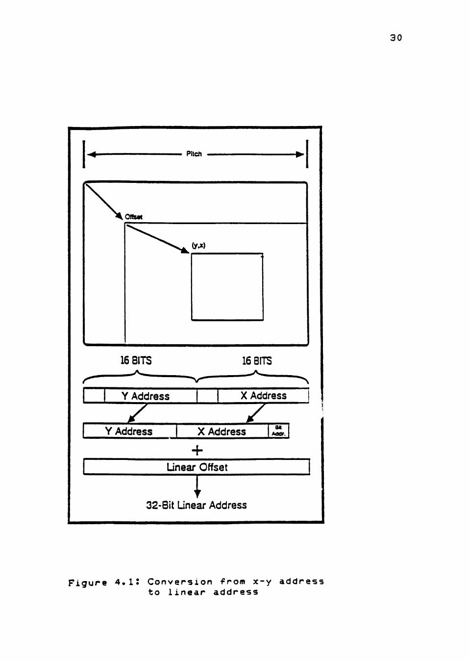
X-Y Addressing
With x-y addressing, a single 32-bit value is treated
as separate 16-bit x and y halves. The two 16-bit values
are converted automatically--within the instructions that
use x-y addressing--to a linear address needed by
memories. The generation of the linear address is a
function of the x and y values, the x-y array's "pitch"
(the linear address difference between two vertically
adjacent pixels), and a 32-bit offset that allows the x-y
address to be relative to any point in memory. The
conversion process is shown in Figure 4.1. The clipping of
30
Pitch
\ onsM
(y^) 4
16 BITS
Z
16 BITS
z Y Address X Address Mat.
Unear Offset
T 32-Bit Linear Address
Y Address X Address
Figure 4.i: Conversion from x-y address to linear address
31
figures and arrays to fit within a rectangular region is
also supported by x-y addressing.
Other instructions for x-y address manipulation
perform x-y addition, subtraction, and comparison. Moves
between registers of x or y halves are also provided.
PixBlT
The pixel block transfer instructions give the user a
powerful tool for manipulating two-dimensional arrays of
pixels. Pixblt supports the combinations of two
rectangular arrays of pixels using any of the 22 Boolean
and arithmetic pixel processing operations, plus
transparency, plane masking, and window clipping options.
In addition to simple filling, the FILL instruction
supports a single value operating on a rectangular array
of pixels with any of the pixel processing options.
The basic pixblt instruction combines the pixels in
the source array with those in the specified destination
array. The relative word alignments of the source and
destination arrays can be totally arbitrary. Edge
conditions are taken care of, and pixels are moved a
memory word at a time except at the edges, where read-
modif y-wr ites may have to be performed. An add'^d
complication for the two-array transfer is the bit
alignment of the source and destination arrays, which may
32
be aligned differently with respect to memory word
boundaries. Thus the source data must be shifted to align
to the destination location before it can be written. This
instruction aligns the source and destination arrays
automatically and with very little, if any, decrease in
performance.
An important feature supported in pixblts is the
ability to have different values for the source and
destination pitches. For example, an array only 16 bits
wide can be stored off screen packed as 16-bit words. When
transferred to the bitmap, the source pitch is 16 bits,
while the destination pitch is the number of bits in one
line of display memory.
Window Clipping
A window is specified as a rectangular region that is
optionally protected from being overwritten. Probably the
most common use is the implementation of a viewport
concept. Only the pixels that lie within the window are
written to the bitmap.
Four different window clipping options are supported.
The "no clipping" option ignores windowing boundaries and
does not protect any pixels. The "clip-to-fit" option
prohibits pixels outside the window from being written.
The "interrupt on window violation" immediately aborts the
33
operation if any point in an operation will lie outside
the window. The window violation interrupt is then set and
will be taken immediately if it is enabled. The "pick"
option determines whether any pixel lies within the
window. With the pick option, all pixel drawing is
inhibited and the window violation interrupt is issued
whenever a pixel would be drawn within the pick region.
For the pixblt instructions with the clip-to-fit
option, the destination array is preclipped to the window
before any data is transferred. This preclipping avoids
the potential waste of large amounts of time computing
addresses ^or pixel transfers that will end up being
clipped. Adjustment of the source array is based on
adjustment of the destination array.
Pixel Processing
Every pixel transferred with the graphics
instructions of the 34010 can use pixel processing
operations, which combine each source pixel with the
corresponding destination pixel before overwriting the
destination pixel with the result. Both logical and
arithmetic processing are supported. Less familiar but
very important for pixblts are thp arithmetic operations
that operate on entire pixels rather than on the
ndividual bits within pixels. For multiple-bits-per-pixe1
34
applications, these operations are not only desirable but
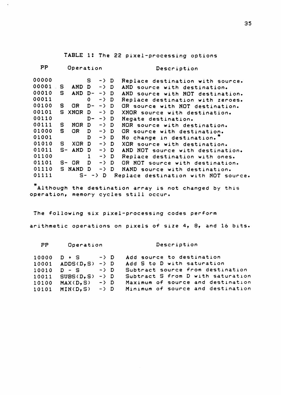
necessary. Six of these options are supported. The entire
list of 22 pixel processing options is shown in Table 1.
Plane Mask
The plane mask enables the user to inhibit writes to
some or all of the bits within a pixel. For example, when
a pixel contains information for a group of planes, the
bits associated with a given plane or planes can be
protected. Thus text can be modified in one plane while
the graphics information in other planes remains
unaffected. This mask is applied to pixel data as it is
read into the chip as well as to the data to be written
externally.
Transparency
Transparency detection can be selected to treat zero-
value pixels as transparent. This detection is applied to
the result of pixel processing and plane masking. With
transparency enabled, a pixel o-f zero value does not
overwrite the destination pixel, leaving the background
unchanged. In this way, only the part of a rectangular
array that makes up the desired shape (such as a text
character) is actually written. The overlaying of text on
graphics then becomes a very simple task.
35
TABLE IJ The 22 pixe1-processing options
PP
00000 00001 00010 00011 00100 00101 00110 00111 01000 01001 01010 01011 01100 01101 OHIO 01111
s s
s s
s s
s s-
Operation
s AND D AND D-
0 OR
XNOR
Description
> D Replace > D AND sour > D AND sour > D Replace
D- -> D OR sourc D -> D XNOR sou D- -> D Negate d
NOR D -> D NOR sour OR D -> D OR sourc
D -> D No Chang XOR D -> D XOR sour AND D -> D AND NOT
1 -> D Replace S- OR D -> D OR NOT s S NAND D -> D NAND sou
S- -> D Replace de
desti ce wi ce wi desti e wit rce w estin ce wi e wit e in ce wi sourc desti ource rce w st ina
nation th dest th NOT nation h NOT d ith des ation. th dest h desti destina th dest e with nation with d ith des tion wi
with source, ination. destination, with zeroes, estination. tination.
ination. nation. tion. ination. destination. with ones. estination. tination. th NOT source.
Although the destination array is not changed by this operation, memory cycles still occur.
The following six pixel-processing codes perform
arithmetic operations on pixels of size 4, 8, and 16 bits
PP Operation Descr iption
10000 D • S -> D 10001 ADDS(D,S) -> D 10010 D - S -> D 10011 SUBS(D,S) -> D 10100 MAX(D,S) -> D 10101 MIN(D,S) -> D
Add source to destination Add S to D with saturation Subtract source from destination Subtract S from D with saturation Maximum of source and destination Minimum of source and destination
36
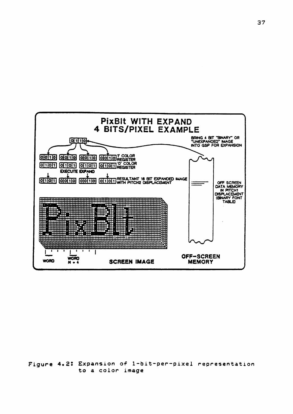
Expand
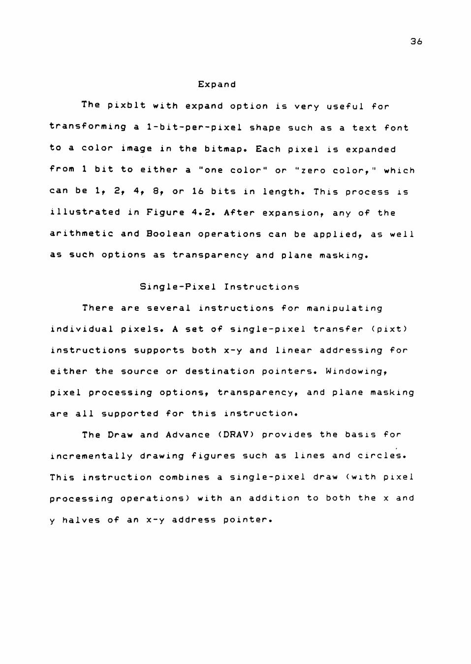
The pixblt with expand option is very useful for
transforming a 1-bit-per-pixel shape such as a text font
to a color image in the bitmap. Each pixel is expanded
from 1 bit to either a "one color" or "zero color," which
can be 1, 2, 4, 8, or 16 bits in length. This process is
illustrated in Figure 4.2. After expansion, any of the
arithmetic and Boolean operations can be applied, as well
as such options as transparency and plane masking.
Single-Pixel Instructions
There are several instructions for manipulating
individual pixels. A set of single-pixel transfer (pixt)
instructions supports both x-y and linear addressing for
either the source or destination pointers. Windowing,
pixel processing options, transparency, and plane masking
are all supported for this instruction.
The Draw and Advance (DRAV) provides the basis for
incrementally drawing figures such as lines and circles.
This instruction combines a single-pixel draw (with pixel
processing operations) with an addition to both the x and
y halves of an x-y address pointer.
37
PfxBIt WITH EXPAND 4 BITS/PIXEL EXAMPLE
BRING 4 SIT "BWAflY- OR IJNEXPANOEO' IMAGE INTO GSP FOR EXPANSION
IREGJSTER
| 5pm i nToin fornoTTi ^EEB'^^^ EXECUnE eCPANO
i f e m (Oiohol f o i o ^ (0 l ] fe«^SULTANT 16 BfT EXPANDED IMAGE \MTH PITCH2 OISPLACEMENT
•••••••••••••••••••••a •^•B ••••«•••••••••••••••••••••••• - - , •••••«••••••••••••••• ' • •• -• #•••, ••••••^^••••••••••••••••••••s
•••• ••••• •••••••••••••••••••••v''V*vas* ••* •«••• ••••«•••••••••••••••• »•••• •••••• ••••••••••••••••••••• •••«•• •«-. •••«•«.. • ••• . •••«•«• •••••••••••••••««•«••.: «aa«a«9 ••• ••«•«• . • •••' •••••• ••• , «•••••«•>••••••« •••••A •*. ••••••^ •••••••«••••••••••••• • " T ' * * n * • • • • • • • • • • • • • • • • • • • a i . a A B A A • • « - • • • • • A > • • • • • • « • « • • • • • • • • • • • • • • « • - lB««Ba««aaaa«B««aasaaaa . . 4 * « * • • •
- _ ' • •a8aaa«aa*B«a««aa«aaaa« • d a a a . aaa ' a v n a a a a a a a
' aaaaa.^ aaaaaS a a •aaaafli aaaaaafl • •
a a S ^ • • • a a a * ' aaaaaai • aa««a
' Snaaaaaaaaaaaaaaaaaa^^^^l • . aaaaaaaaaaaaaaaaaaaaa^^^^
a* » aaaaaaaa* i a a « mmm aas ^ ^ Baaaa
•iiiiniiiiiiiiiiiiiiiniiimiT'" I I
aaaa«a«aa««a«aa»aaa«a«aa«aaaaaaaa««aaaaa»2rr»
OFF SCREEN DATA MEMORY
IN PfTCHI OISPLACEMENT (BINARY FONT
TA8LQ
n»»»»m»»»{»{»»»l{»»»»
worn WORD N • 4 SCREEN IMAGE
OFF-SCREEN MEMORY
F i g u r e 4*2* E x p a n s i o n of 1 - b i t - p e r - p i x e l r e p r e s e n t a t i o n t o a c o l o r image
38
Compare Point to Window
One additional instruction extremely useful in the
software implementation of many graphics algorithms is
Compare Point to Window (CPW). Executing in a single
cycle, CPW compares the x and y values of a given point to
the corresponding values of both the window start and
window end registers, generating a 4-bit code. This code
indicates in which of the nine regions relative to the
window the point lies. This concept, is best known for its
use in the Cohen-Sutherland line clipping algorithm.
Summary
The design philosophy was, to support whatever
graphics functions are required in any application rather
than to restrict graphics to a few primitive functions.
Consequently, the 34010 provides a unique combination of
general programmabi1ity and graphics processing power on a
single integrated chip. As a result, systems developers
can program the 34010 to do any graphics or non-graphics
task.
CHAPTER V
FUNCTIONAL DESCRIPTION AND
IMPLEMENTATIONAL DETAILS
Introduction
The GKS standard, as already discussed in chapter II,
is based upon the seven major conceptual elements, which
are output, input, workstations, coordinate systems and
transformations, windows and viewports, segments, and
levels of functionality. They were chosen in order to
provide a set of functions for computer graphics
programming that can be used by a majority of applications
that produce computer generated pictures.
The purpose of this chapter is to discuss in detail
the different GKS functions that have been implemented to
help achieve the research objective, which is to determine
if GKS is a viable standard for the TMS 34010 Graphic
System Processor available ior PCs. These functions were
chosen for the implementation because they are the
basic graphical functions of "Minimal GKS" C17], which is a
subset of the Graphical Kernel System standard. Research
conducted at Sandia Laboratories has demonstrated that
Minimal GKS is easy to learn and use, yet powerful enough
for non-trivial, real-world applications. The approach
adopted is to describe each GKS function and its
39
40
requirements followed by its parameter description
(language independent). This is followed by what features
the 34010 offers for efficiently implementing this
function and how these features help. This is followed by
a discussion of whether the GKS requirements can be easily
met using these features. This is followed by the
algorithm chosen for the implementation.
Fill Area Function and its Requirements
The GKS Fill area function generates a closed
polygon which may be hollow or filled with a uniform color
or a pattern. This function's purpose is the display of
areas. The areas are defined by their bounding polygons.
There are no restrictions concerning the shape of the
polygon? it may be a convex polygon or a seIf -1ntersectmg
polygon. However, insular structures, i.e., areas with
holes which need several separate polygons to be defined,
have been excluded from GKS. Such structures were regarded
as being outside the scope of a kernel system and,
therefore, must be handled on top of GKS.
The parameters of the GKS Fill Area function are
the number of points n defining the fill area boundary
(where n >= 3 ) , and the coordinates of those n points in
w orld coordinates.
41
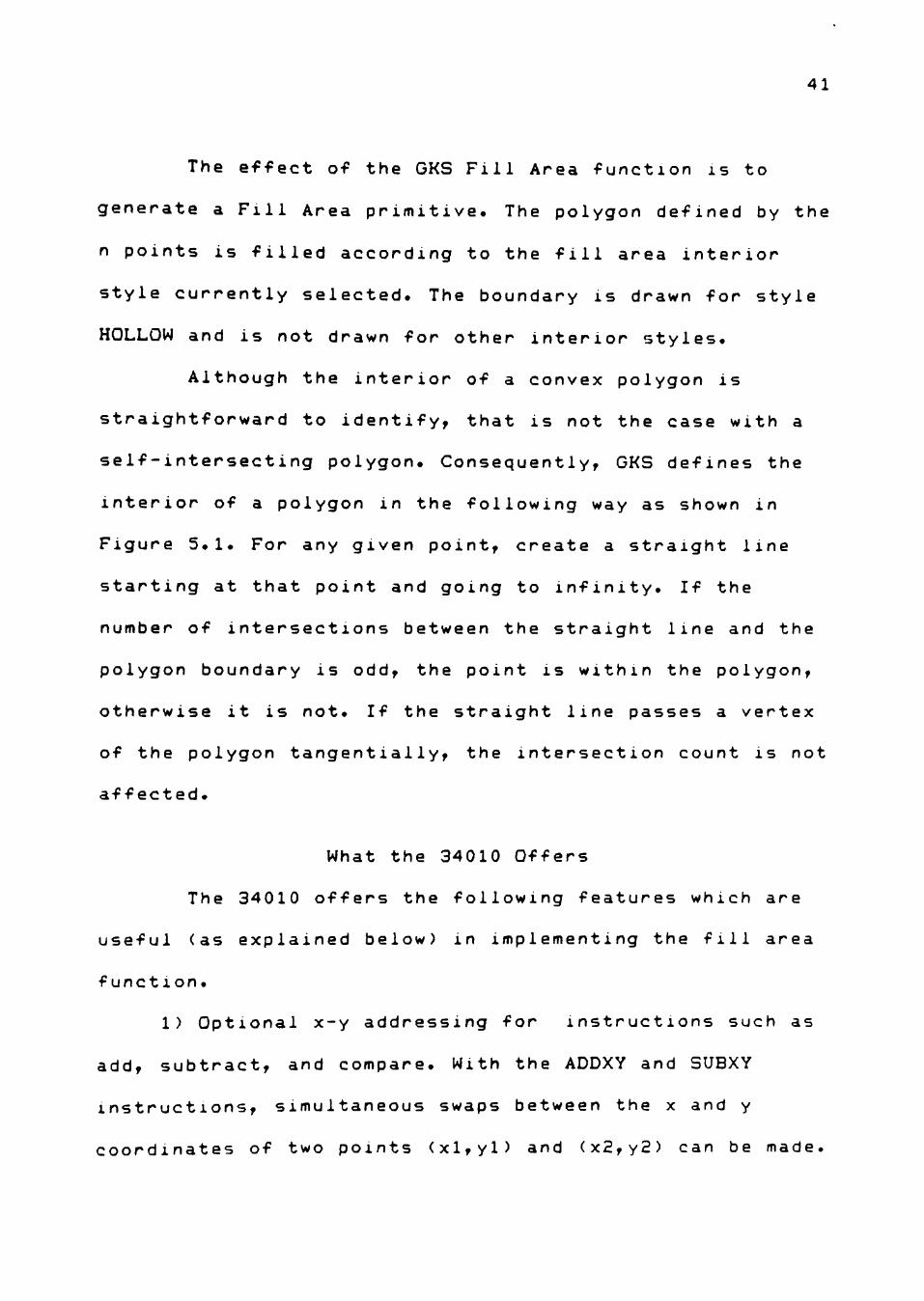
The effect of the GKS Fill Area function is to
generate a Fill Area primitive. The polygon defined by the
n points is filled according to the fill area interior
style currently selected. The boundary is drawn for style
HOLLOW and is not drawn for other interior styles.
Although the interior of a convex polygon is
straightforward to identify, that is not the case with a
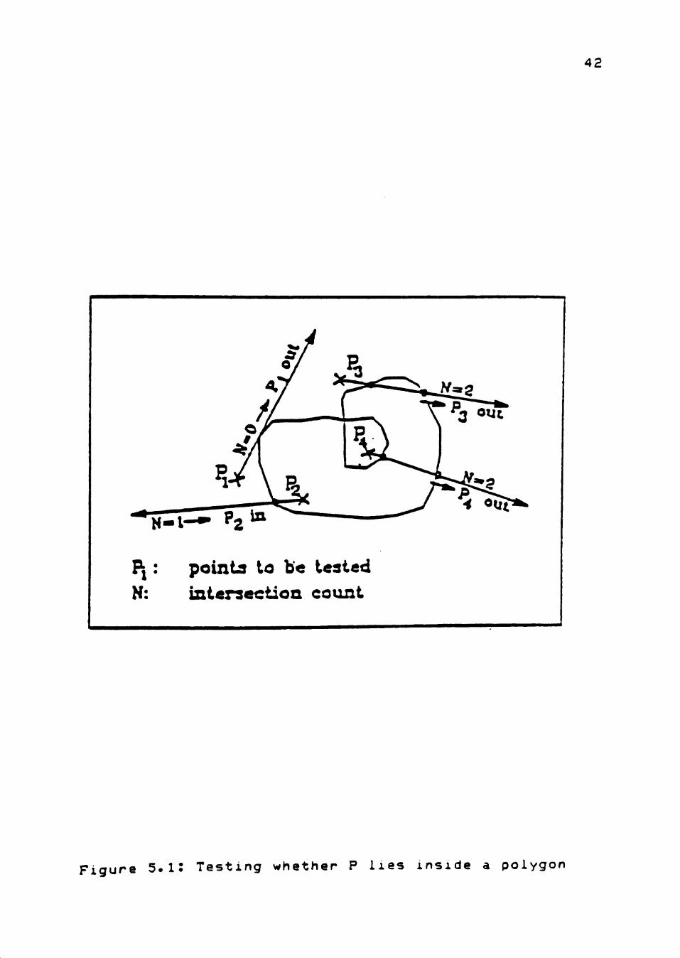
self-intersecting polygon. Consequently, GKS defines the
interior of a polygon in the following way as shown in
Figure 5.1. For any given point, create a straight line
starting at that point and going to infinity. If the
number of intersections between the straight line and the
polygon boundary is odd, the point is within the polygon,
otherwise it is not. If the straight line passes a vertex
of the polygon tangentially, the intersection count is not
affected.
What the 34010 Offers
The 34010 offers the following features which are
useful (as explained below) in implementing the fill area
function.
1) Optional x-y addressing for instructions such as
add, subtract, and compare. With the ADDXY and SUBXY
instructions, simultaneous swaps between the x and y
coordinates of two points (xl,yl) and (x2,y2) can be made.
42
?l: points to be tested N: intersection count
Figure 5.i: Testing whether P lies inside a polygon
43
This kind of swapping is required when sorting the
vertices of a polygon or when drawing the outline of the
polygon to be filled and y2 is less than yl. With the
CMPXY instruction, the x and y coordinates of two points
(xl,yl) and (x2,y2) can be simultaneously compared. This
IS useful in determining the minimum enclosing rectangle
for the polygon to be filled and in clipping the minimum
enclosing rectangle to the window region specified by the
WSTART and WEND registers.
2) Moves between registers of x and y halves. With
the MOVX and MOVY instructions, the x portion alone or the
y portion alone of a point can be changed without
affecting the other portion of the point. This is also
useful in determining the minimum enclosing rectangle of
the polygon to be filled.
3) A pixel block transfer instruction. This
instruction is useful in implementing a pattern fill on a
polygon. It is achieved by storing the particular pattern
to be used in the form of a bit map and transferring the
bit map onto the screen using the PIXBLT instruction.
During execution, the PIXBLT instruction expands the
zeroes in the bit map into the background color (color
value stored in register B8) and the ones in the bit map
44
into the foreground color (color value stored in register
B9).
4) A single CPU cycle left-most-one instruction. This
instruction is very useful in scanning the horizontal line
for fill regions.
5) Allows the number of bits per pixel to be
programmed. This makes it easy to draw the outline of the
area to be filled in a 1-bit-per-pixel scratchpad area by
setting the pixel size to one bit.
Can GKS Requirements be Easily Met?
The GKS requirements for the fill area function can
be easily met using the above features of the 34010. There
are many different approaches to area filling, and often
there are very important trade-offs between the speed and
the complexity of the object that each algorithm can
render. As already mentioned, GKS does not place any
restriction on the type of polygon that can be defined by
an application program. The polygon can be a convex
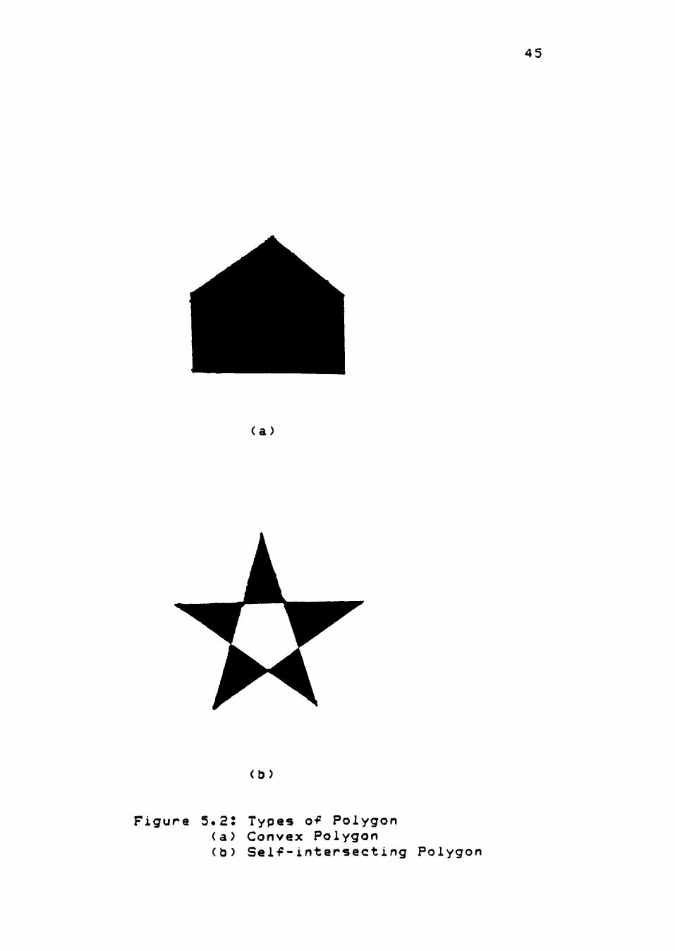
polygon as in Figure 5.2(a) or it can a self-intersecting
polygon as in Figure 5.2(b).
Implementation Approach Adopted
One way to implement area filling is as follows
First compute and store (in an array) all of the
45
(a)
(b)
Figure 5.2: Types of Polygon (a) Convex Polygon (b) Self-intersecting Polygon
46
intersections of the horizontal scan lines with the lines
making up the boundary of the area to be filled. Then sort
these by values of y and then by values of x. Once this is
done, the filling is achieved by plotting horizontal lines
between pairs of coordinates from the above array. But
there are two major problems with this method. First, the
size of the array must be predicted very closely.
Moreover, even for small fill areas, the size of the array
required is large and thus this method is inefficient in
terms of memory usage. Second, this method cannot handle a
self-intersecting polygon like the one shown in Figure
5.2(b).
An alternate approach computes and stores at one
time, only the intersections of one horizontal scan line
with the boundary of the area to be filled and plots
horizontal lines between the appropriate pairs of
coordinates. This way, the size of the array required is
reduced. But, this affects the area filling speed by
adding computations inbetween every two horizontal scan
lines. Also, self-intersecting areas cannot be handled by
this method either.
Another method to implement filled polygons is to
first draw the outlines defining the polygon at 1 t*it per
pixel into a scratchpad area. The scratchpad will have a
1-bit-per-pixel mapping of the screen image and is at
47
least as large as the minimum enclosing rectangle of the
image. Once the outline is drawn, the pixel size is reset
to 4 bits and each horizontal line of the scratchpad space
is scanned for fill regions along that line. A bit value
of one represents an edge of a fill region, and each pair
of one bits represents a horizontal fill region. Once a
fill region is identified, filling is done to the
corresponding part of the display memory at the full pixel
depth which is 4 bits. This method can handle self-
intersecting polygons in addition to not requiring a lot
of memory.
Since this method helps satisfy all of the GKS
requirements for the Fill Area function, this method was
adopted for this implementation.
Polvli ne Function and its Requ irements
The GKS Polyline function generates a sequence of
straight lines which connects the given points. The points
are specified in world coordinates. GKS requires a minimum
of four different line types (SOLID, DASHED, DOTTED and
DASH-DOT) to be offered by any GKS implementation.
The parameters of the GKS Polyline function are the
number of points n defining the (n-1) line segments (where
n >= 2), and the coordinates of those n points in world
coordinates.
48
The effect of the GKS Polyline function is to
generate a sequence of connected straight lines, starting
from the first point and ending at the last point.
What the 34010 Offers
The 34010 offers a LINE instruction which performs
the Bresenham line-drawing algorithm. All that is needed
is to setup the initial values (shown in the pseudo-code
below) in the appropriate B file registers and then to
call the LINE instruction.
The Bresenham algorithm is the most popular
algorithm for drawing lines. It converts the equation of a
line into an iterative process of comparing test values
over the horizontal distance subtended by the line. The
values are incremented and tested repeatedly. Each time
the value of x or y increases to make a new pixel
possible, the pixel is plotted. The test increments are
derived before the line is drawn, from the slope of the
line and the differentials of its horizontal and vertical
components. The pseudo-code for the algorithm follows.
Pseudo-code for Bresenham 's line drawi ng algor i thm
Given a line from (xl,yl) to (x2,y2)
dx is the difference between the x components of endpoints dy IS the difference between the y components of endpoints IX is the absolute value of dx
49
iy is the absolute value of dy inc is the larger of dx and dy
plotx is xl
ploty is yl (the beginning of the line) X starts at 0 y starts at 0
plot a pixel at plotx, ploty
for i = 0 to inc step 1
increment x using ix increment y using iy set plotflag to FALSE
if X > inc set plotflag to TRUE decrement x using inc increment plotx if dx is positive
otherwise decrement plotx endif
if y > inc set plotflag to TRUE decrement y using inc increment ploty if dy is positive
otherwise decrement ploty endif
if plotflag is TRUE plot a pixel at plotx,ploty
}
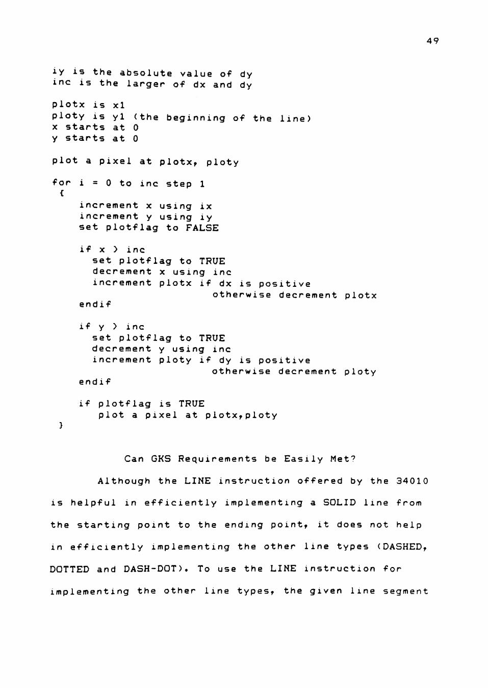
Can GKS Requirements be Easily Met?
Although the LINE instruction offered by the 34010
IS helpful in efficiently implementing a SOLID line from
the starting point to the ending point, it does not help
in efficiently implementing the other line types (DASHED,
DOTTED and DASH-DOT). To use the LINE instruction for
implementing the other line types, the given line segment
50
must be broken down into smaller solid line segments
(depending upon the line type chosen) and the LINE
instruction invoked. This would involve a lot of
computation which will affect the drawing speed. Also, for
different line types, the code for breaking down the line
segment into smaller solid segments will be different.
An alternative approach for implementing other than
SOLID line types, would be to use the pixel transfer
instruction PIXT (plots a single pixel), and plot only the
pixels that need to be displayed depending upon the line
type chosen. The actual procedure adopted is described
below.
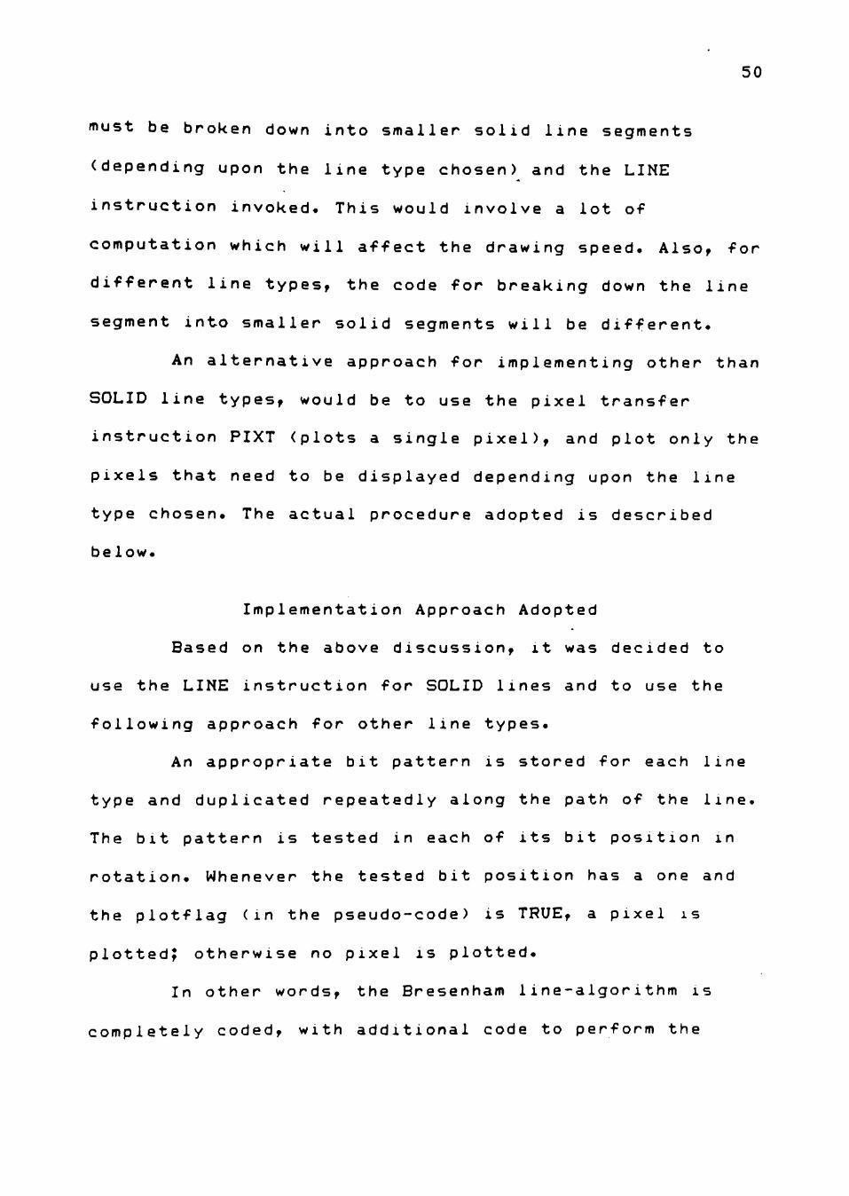
Implementation Approach Adopted
Based on the above discussion, it was decided to
use the LINE instruction for SOLID lines and to use the
following approach for other line types.
An appropriate bit pattern is stored for each line
type and duplicated repeatedly along the path of the line.
The bit pattern is tested in each of its bit position in
rotation. Whenever the tested bit position has a one and
the plotflag (in the pseudo-code) is TRUE, a pixel is
plotted? otherwise no pixel is plotted.
In other words, the Bresenham line-algorithm is
completely coded, with additional code to perform the
51
above mentioned testing before plotting each pixel. The
actual code is shown in the appendix.
Text Function and its Requirements
Pictures usually contain inscriptions giving
additional textual information. The GKS text function
allows the generation of character strings on the display
surface. The application program specifies the character
string and GKS automatically translates this string into
geometrical data describing the shape of the individual
characters in the string. Any GKS implementation is
required to support at least the ASCII-character set.
Also, GKS allows textual information to be displayed at
different sizes.
The parameters of the GKS Text function are the
starting point where the text is to be displayed (in world
coordinates), and the character string that needs to be
displayed.
The effect of the GKS Text function is to generate
the character string specified. The text position which is
given in world coordinates is transformed to device
coordinates before being used for displaying the character
string.
52
What the 34010 Offers
The 34010 offers the pixel block transfer
instruction with expand option (Figure 4.2). This proves
very useful in transforming a 1-bit-per-pixel shape such a
text font to a color image on the display. A "one" in the
bitmap is expanded to the foreground color and a "zero" in
the bitmap is expanded to the background color. The
background and the foreground colors themselves are stored
using 4 bits (pixel size) in the B8 and B9 registers
respectively.
Can GKS Requirements be Easily Met?
Although the above mentioned 34010 feature can help
in implementing the GKS text function in an efficient
fashion, the resulting textual information will be of a
fixed size only. But GKS allows text to be displayed at
arbitrary sizes. Even if a whole lot of different-sized
characters are stored in the form of bitmaps, the number
of different sizes available would still be limited. Also,
this approach would be inefficient in terms of storage
memory.
Thus the GKS requirement cannot be easily met using
the above feature.
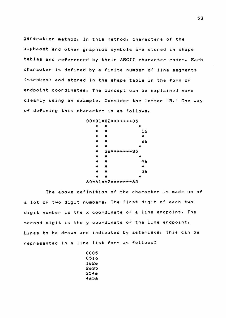
An alternative approach to implementing the GKS
Text function is to use the stroked character text
53
generation method. In this method, characters of the
alphabet and other graphics symbols are stored in shape
tables and referenced by their ASCII character codes. Each
character is defined by a finite number of line segments
(strokes) and stored in the shape table in the form of
endpoint coordinates. The concept can be explained more
clearly using an example. Consider the letter "B. " One way
of defining this character is as follows.
00*01**02****^»**05
* * 16 * » #
* * 26
» 32»#»»M#»35
* » 46
M M 56 M M M
60*61*62*******65
The above definition of the character is made up of
a lot of two digit numbers. The first digit of each two
digit number is the x coordinate of a line endpoint. The
second digit is the y coordinate of the line endpoint.
Lines to be drawn are indicated by asterisks. This can be
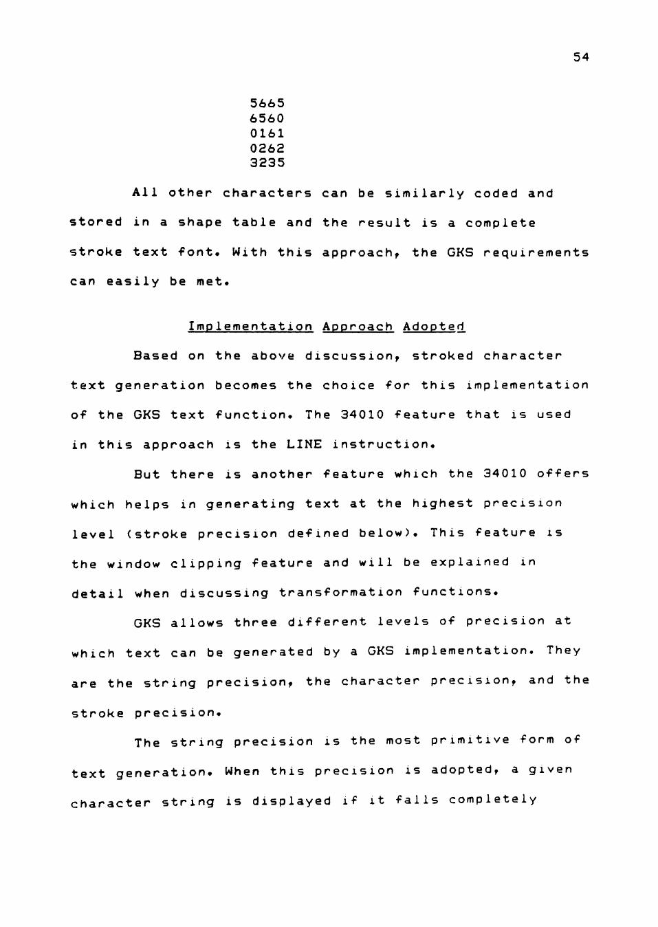
represented in a line list form as follows! 0005 0516 1626 2635 3546 4656
54
5665 6560 0161 0262 3235
All other characters can be similarly coded and
stored in a shape table and the result is a complete
stroke text font. With this approach, the GKS requirements
can easily be met.
Implementation Approach Adopted
Based on the above discussion, stroked character
text generation becomes the choice for this implementation
of the GKS text function. The 34010 feature that is used
in this approach is the LINE instruction.
But there is another feature which the 34010 offers
which helps in generating text at the highest precision
level (stroke precision defined below). This feature is
the window clipping feature and will be explained in
detail when discussing transformation functions.
GKS allows three different levels of precision at
which text can be generated by a GKS implementation. They
are the string precision, the character precision, and the
stroke precision.
The string precision is the most primitive form of
text generation. When this precision is adopted, a given
character string is displayed if it falls completely
55
within the selected window region. If not, the whole
character string is discarded.
The character precision is better than the string
precision. When this precision is adopted, only those
characters (of the given character string) that are not
completely inside the selected window region are
discarded.
The stroke precision is the highest precision level
at which text can be displayed in a GKS implementation.
When this precision is adopted, only those portions of the
character that overlaps a window boundary are discarded.
The other parts of the character as well as the other
characters of the given string are displayed.
Transformation Functions and and their Requirements
Normalization Transformation Functions
A normalization transformation is defined by two
rectangles, a "window" within world coordinate space and a
"viewport" within the range CO,l]xCO,l] of NDC space. The
window and the viewport together define a transformation
which maps the content of the window onto the viewport.
Although GKS allows several normalization
transformations to be defined, only one of them can be
active for output of primitives at any time.
56
The parameters of the GKS Set Window function are
the transformation number n (where n >= 0) and the window
limits XMIN, XMAX, YMIN, and YMAX in world coordinates
(where XMIN < XMAX and YMIN < YMAX).
The parameters of the GKS Set Viewport function are
the transformation number n (where n >= 0) and the
viewport limits XMIN, XMAX, YMIN, and YMAX in normalized
device coordinates (where XMIN < XMAX and YMIN < YMAX).
Workstation Transformation Functions
The workstation transformation is specified in a
manner similar to the normalization transformation by a
window within the range C0,l]xC0,13 of the NDC, called the
"workstation window," and by a viewport within the display
surface, called the "workstation viewport." GKS requires
an application program to define both the workstation
window and the workstation viewport with the same aspect
ratio. If they are not defined so, the GKS implementation
should shrink the workstation viewport to a rectangle with
the same aspect ratio as the workstation window.
The parameters o-f the GKS Set Workstation Window
function are the workstation identifier and the
workstation window limits XMIN, XMAX, YMIN, YMAX in
normalized device coordinates (where XMIN < XMAX and YMIN
< YMAX).
57
The parameters of the GKS Set Workstation Viewport
function are the workstation identifier and the
workstation viewport limits XMIN, XMAX, YMIN, YMAX in
device coordinates (where XMIN < XMAX and YMIN < YMAX).
Clipping
GKS provides a mechanism to clip graphical output
to a clipping rectangle. All parts of primitives within or
on the boundary of the clipping rectangle will be
displayed. Everything else will be discarded. This applies
to all output primitives.
The GKS clipping mechanism involves both the
normalization transformation and the workstation
transformation. The clipping rectangle is obtained by
determining the intersection of the viewport rectangle and
the workstation window rectangle. The actual clipping is
performed against the clipping rectangle when output is
displayed on a workstation.
The parameter of the GKS Set Clipping Indicator
function is the clipping indicator (CLIP or NOCLIP).
What the 34010 Offers
The 34010 provides a hardware window clipping
feature that confines graphics drawing operations to a
specified rectangular window. The limits of the current
58
window are specified in the WSTART (window start) and WEND
(window end) registers. WSTART specifies the minimum XY
coordinates in the window, and the WEND specifies the
maximum XY coordinates in the window.
Can GKS Requirements be Easily Met?
Yes, the GKS requirements can be easily met using
the above feature of the 34010. All that needs to be done
is to determine the intersection of the viewport rectangle
and the workstation window rectangle and store the
starting and ending corners of this rectangle in the
WSTART and WEND registers. Once this is done, all the
output primitives that are written to the display surface
are automatically clipped to this window.
Summary
This chapter described the different GKS functions
that were implemented and the algorithms that were chosen
for the implementation along with the reasons for choosing
them. The different features offered by the 34010 for
implementing each of these GKS functions were also
discussed.
CHAPTER VI
CONCLUSION
Testing
The GKS functions implemented were tested for
correctness from a functional point of view. In functional
testing, the program or system is treated as a black box.
It is subjected to different inputs, and its outputs are
verified for conformance to expected results. The
software's ultimate user is concerned only with function,
and hence functional testing inherently takes the user's
point of view.
Expected results were generated for all the
different inputs used for testing. Sample outputs
generated by the text, filiarea, and the polyline
functions are shown in Figure 6.1 through Figure 6.8.
These figures show only relevant portions of the display
screen.
GKS Text Function
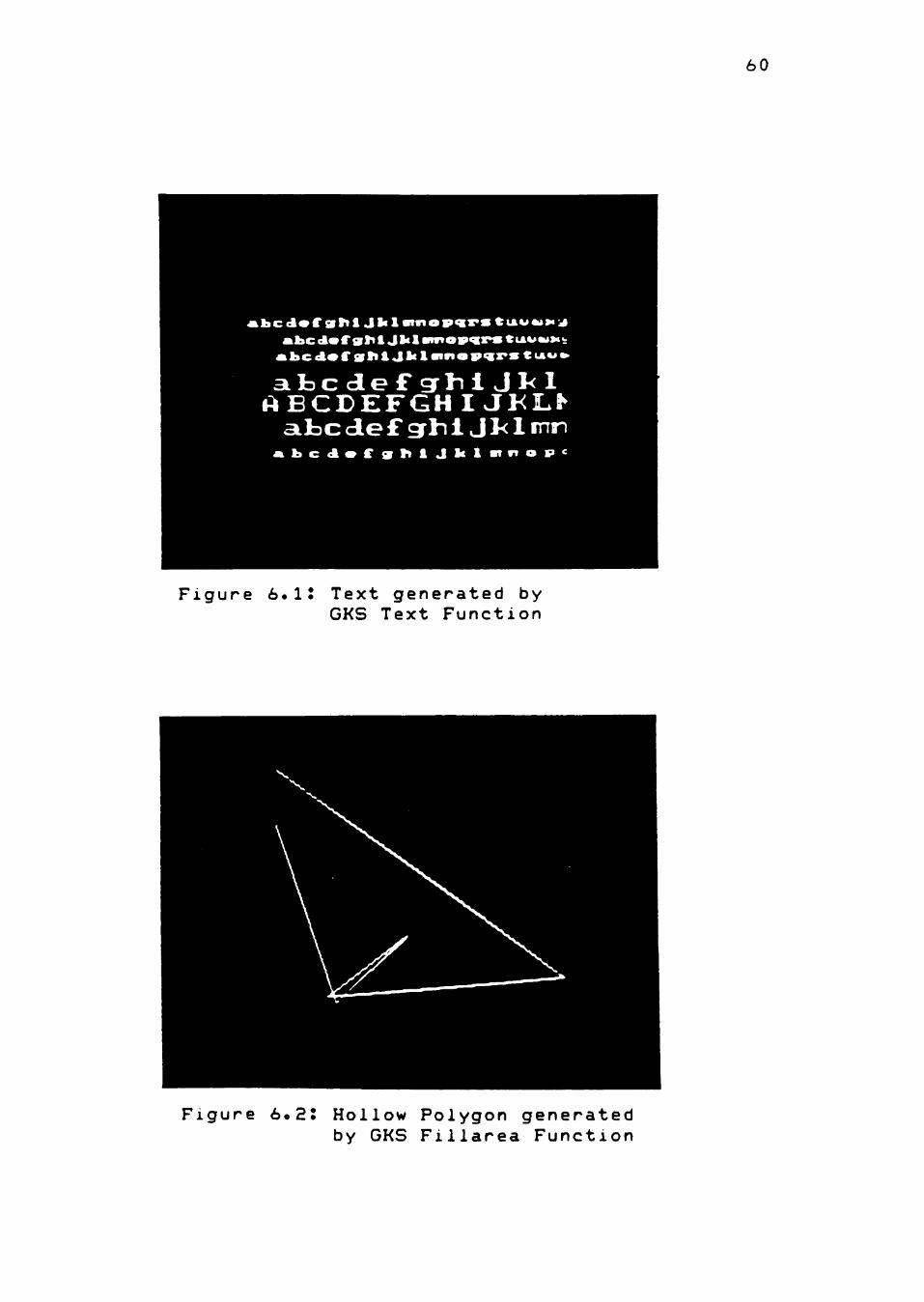
Figure 6.1 is a sample output generated by the GKS
Text Function. Seven different text strings are displayed.
The trailing end of each of the seven text strings has
been truncated at the clipping window boundary. The last
character of the second, third, fifth, and the seventh
59
60
t b c (A«C sitt i J I* 1 a i n o w x * s ^iA«'*>>* ^ a b c < I * r v r i i J l « l a n n o v ^ s ^ CUIVWM^
Al>c<t*rgrt»&JlcIai*io9<cr>sCiA««ft>
a b c d e F g r M J1<1 A B C D E F G H I J K L ^
aifcc d e £ grhi I J 1< 1 nn * l > c < l » f f 9 l t i J l c l a * v t o s > c
Figure 6.1J Text generated by GKS Text Function
Figure 6.2J Hollow Polygon generated by GKS Filiarea Function
61
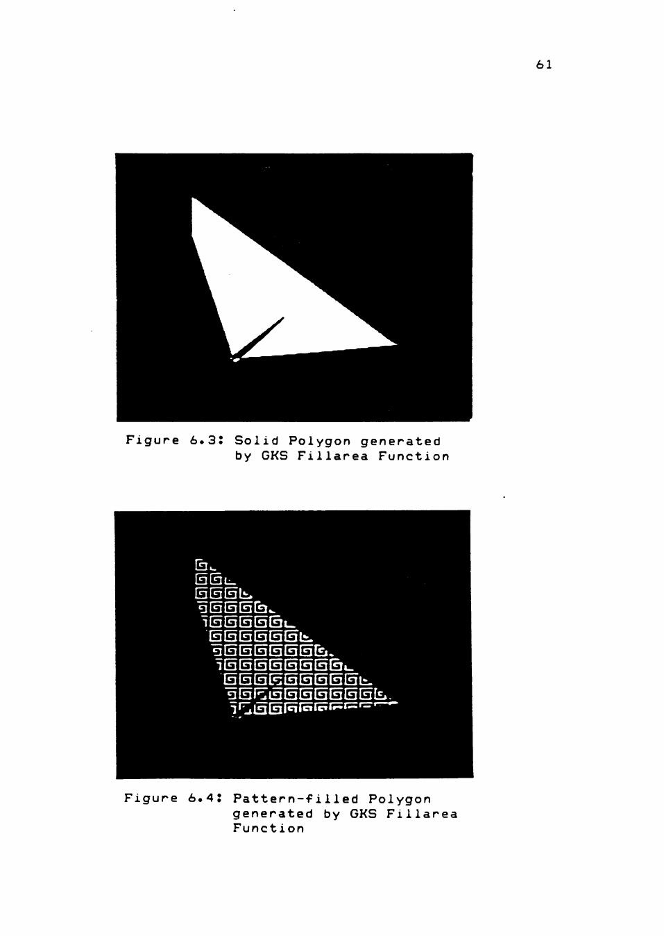
Figure 6.3J Solid Polygon generated by GKS Filiarea Function
S [3 S S S la S S b-3 S lisi I3 S SI3 S S t*. 1 ^mM^^^^'^'^'^
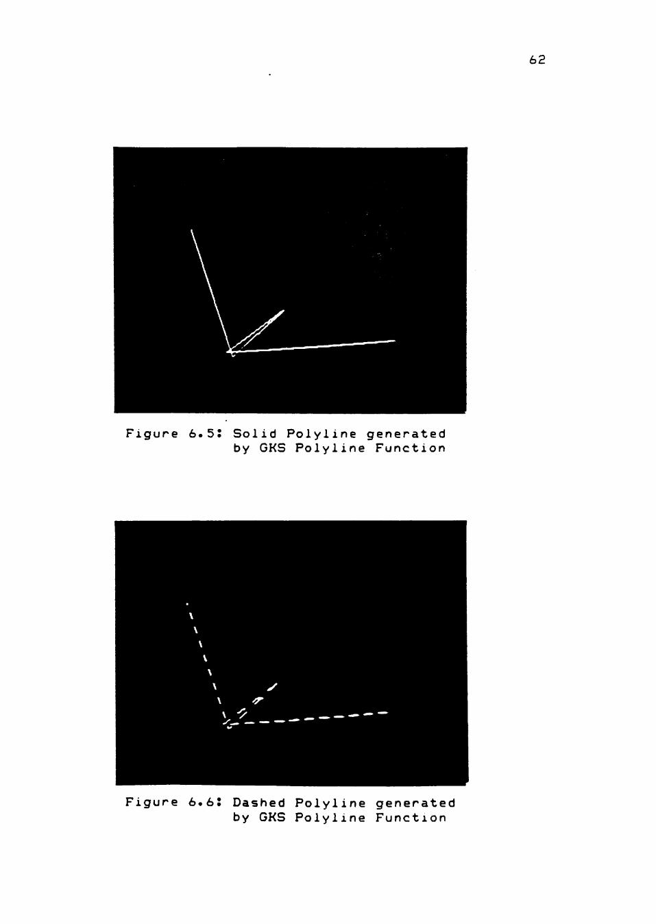
Figure 6.4: Pattern-filled Polygon generated by GKS Filiarea Function
62
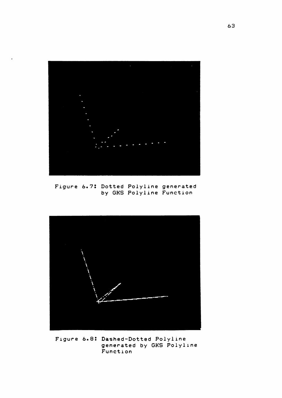
Figure 6.55 Solid Polyline generated by GKS Polyline Function
Figure 6.6J Dashed Polyline generated by GKS Polyline Function
63
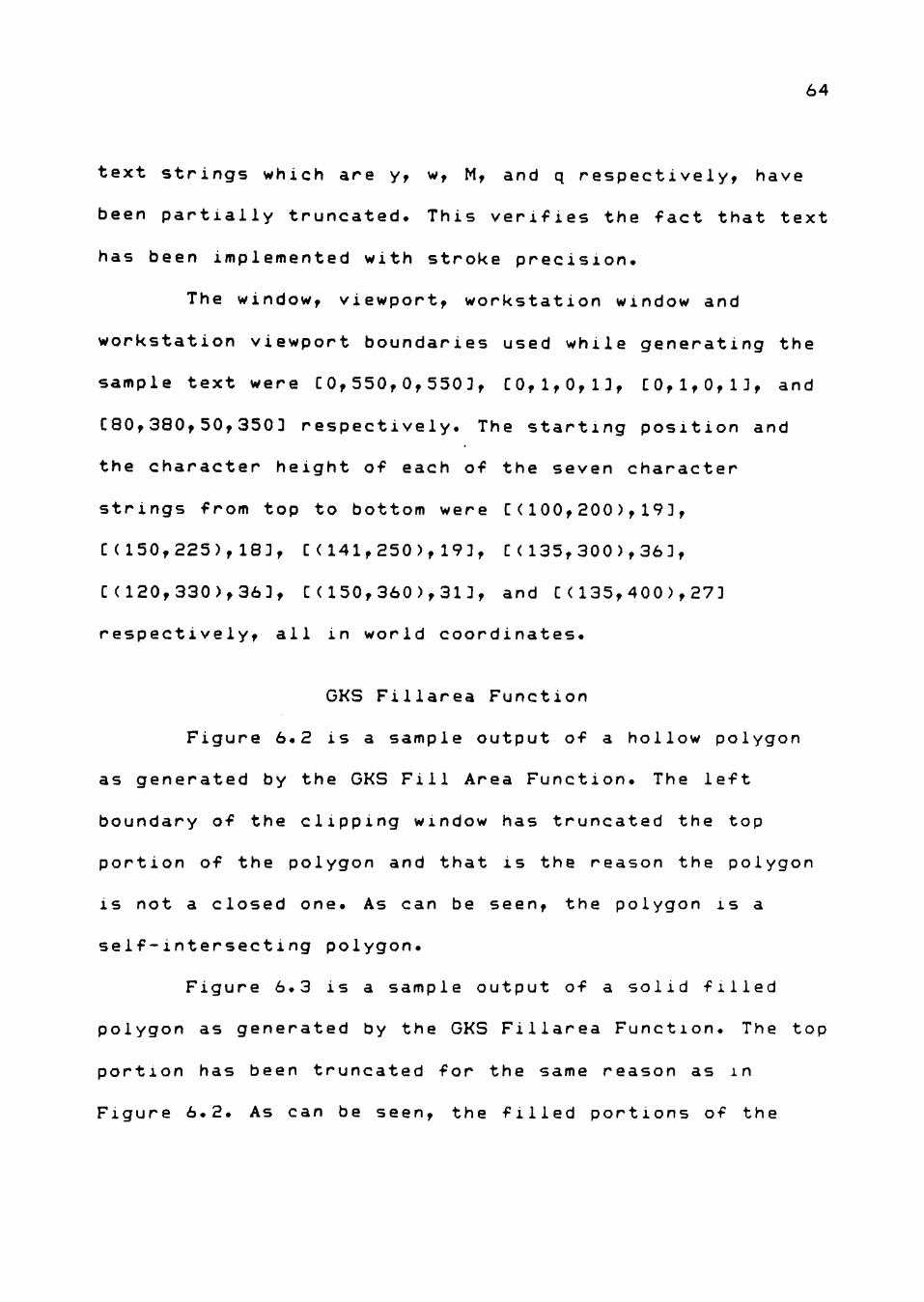
Figure 6.7. Dotted Polyline generated by GKS Polyline Function
Figure 6.8: Dashed-Dotted Polyline generated by GKS Polyline Function
64
text strings which are y, w, M, and q respectively, have
been partially truncated. This verifies the fact that text
has been implemented with stroke precision.
The window, viewport, workstation window and
workstation viewport boundaries used while generating the
sample text were [0,550,0,550 3, CO,1,0,ID, C0,1,0,1J, and
[80,380,50,3503 respectively. The starting position and
the character height of each of the seven character
strings from top to bottom were [(100,200),193,
[(150,225),183, [(141,250),193, C(135,300),363,
[(120,330),363, [(150,360),313, and [(135,400),273
respectively, all in world coordinates.
GKS Filiarea Function
Figure 6.2 is a sample output of a hollow polygon
as generated by the GKS Fill Area Function. The left
boundary of the clipping window has truncated the top
portion of the polygon and that is the reason the polygon
is not a closed one. As can be seen, the polygon is a
self-intersecting polygon.
Figure 6.3 is a sample output of a solid filled
polygon as generated by the GKS Filiarea Function. The top
portion has been truncated for the same reason as in
Figure 6.2. As can be seen, the filled portions of the
65
polygon are in accordance with the GKS definition of the
interior of a polygon as described in Figure 5.1.
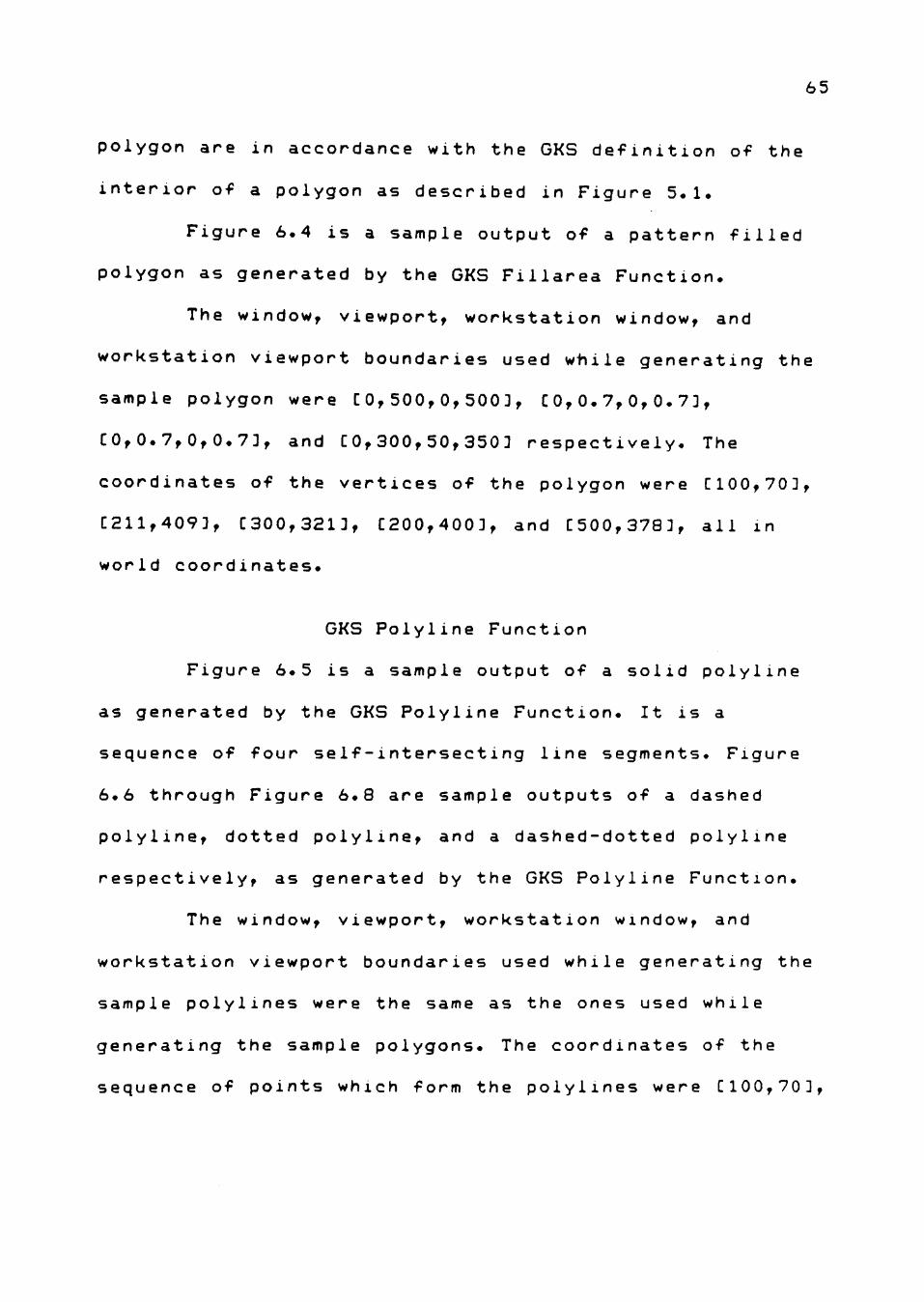
Figure 6.4 is a sample output of a pattern filled
polygon as generated by the GKS Filiarea Function.
The window, viewport, workstation window, and
workstation viewport boundaries used while generating the
sample polygon were [0,500,0,500 3, [0,0.7,0,0.73,
[0,0.7,0,0.73, and [0,300,50,350 3 respectively. The
coordinates of the vertices of the polygon were [100,703,
[211,4093, [300,3213, [200,4003, and [500,3783, all in
world coordinates.
GKS Polyline Function
Figure 6.5 is a sample output of a solid polyline
as generated by the GKS Polyline Function. It is a
sequence of four self-intersecting line segments. Figure
6.6 through Figure 6.8 are sample outputs of a dashed
polyline, dotted polyline, and a dashed-dotted polyline
respectively, as generated by the GKS Polyline Function.
The window, viewport, workstation window, and
workstation viewport boundaries used while generating the
sample polylines were the same as the ones used while
generating the sample polygons. The coordinates of the
sequence of points which form the polylines were [100,703
66
[211,4093, [300,3213, [200,4003, and [500,3783, all in
world coordinates.
Extent of TMS 34010's Utilization
The use made of the 34010 from the point of view of
each of the GKS functions implemented is summarized below.
GKS Polyline Function
The LINE instruction of the 34010 was used for
implementing the SOLID line type. The PIXT (pixel transfer
instruction) instruction was used for implementing the
DASHED, DOTTED and DASH-DOTTED line types, for reasons
mentioned in chapter V. Many steps were saved in
implementing the SOLID line type by using the LINE
instruction because the LINE instruction performs the
Bresenham line-drawing algorithm. But, whatever was gained
was lost in implementing the other than SOLID line types
mentioned above, because the whole algorithm performed by
the LINE instruction had to be recoded with a few
modifications. The net result was that there was no saving
achieved in the code size of the GKS polyline function.
GKS Fill Area Function
The ADDXY, SUBXY, CMPXY, MOVX, MOVY, PIXBLT. and
LMO (Left-Most-One) instructions of the 34010 were used in
implementing the GKS fill area function. Using these
67
instructions saved many steps as explained in chapter V.
Also, the 34010 allows the number of bits per pixel
(PSIZE) to be programmed, which makes it easy to draw the
outline of the area to be filled in a 1-bit-per-pixel
scratchpad area by setting PSIZE to 1. If this feature
were not available, computations have to be performed
using bit masks, to create the 1-bit-per-pixel outline
mentioned above. The net result was that there was a
saving achieved in the code size of the GKS fill area
function.
GKS Text Function
The LINE instruction of the 34010 was used for
implementing the GKS text function. The window clipping
feature of the 34010 was used to achieve the highest
precision level (stroke precision) at which text can be
generated in GKS. This window clipping feature of the
34010 eliminated the need clipping routines to clip output
primitives to the window boundaries. The net result was
that there was a saving achieved in code size of the GKS
text function.
Clipping
The hardware window clipping feature of the 34010
that confines graphics drawing operations to a specified
68
rectangular window, was used to implement clipping. All
that needs to be done is to determine the intersection
(rectangle) of the viewport rectangle and the workstation
window rectangle and store the starting and ending corners
of this rectangle in the WSTART and WEND registers. Once
this is done, all the output primitives that are written
to the display surface are automatically clipped to this
window. The net result was that there was no need for
elaborate clipping routines which means a big saving in
terms of program code.
Result
Computer Graphics programming can be divided into
two major parts. The first part involves transforming
coordinate values from one coordinate system to another
(WC, NDC, DC), which amounts to performing a lot of
computations. The second part involves the actual
generation of images on the computer screen. The first
part is computation intensive. The second part is pixel
manipulation intensive. Consequently, computer graphics
processing becomes a very heavy burden on the processor.
The objective of using the GKS standard
specifications was to achieve portability of graphics
application software. The objective o-f using the Graphic
System Processor was to offload the graphics processing
69
from the main processor, so that the main processor is
f^ree to do some other processing.
From the discussion so far in chapters 5 and 6, it
IS seen that the 34010 helps implement a subset of GKS
(Minimal GKS) efficiently, by allowing savings to be
achieved in the code required to implement the GKS
functions (as explained under the heading "Extent of TMS
34010 Utilization"). It is also seen that the
implementation makes use of the power of the graphics
processor. Also, the main processor is required only to
load the application program along with the required GKS
functions onto the 34010. Once that is done, the
processing is done entirely on the 34010. Thus, the above
mentioned two objectives have been achieved.
In addition to the above mentioned features, the
34010 features an instruction cache, a barrel shifter and
a large register file (30 general-purpose registers). The
barrel shifter helps shifting from 1 to 32 bits in a
single CPU cycle. Graphics operations require the
manipulation of many variables during the drawing process
and the availability of a large register file enhances m e
speed of execution by reducing time-consuming data
swapping between memory and registers. Consequently, tne
overall system performance is also improveo.
70
From the above discussion, it seems that GKS is a
viable standard for the 34010 Graphic System Processor.
Future Work
The research indicated that the 34010 provides features
such as pixel processing, plane masking, and transparency
for performing certain graphics operations.
Pixel processing (PixBLT) operations are useful for
manipulating bit-mapped mixtures of graphics and text.
The plane mask feature enables the user to inhibit
writes to some or all of the bits within a pixel. With
this feature, text can be modified in one plane while the
graphics information in other planes remain unaffected.
With the transparency feature enabled, a pixel of
zero value does not overwrite the destination pixel,
leaving the background unchanged. In this way, only the
part of a rectangular array that makes up the desired
shape (such as a text character) is actually written. The
overlaying of text on graphics then becomes a very simple
task.
Although these above operations will prove useful
in the area of electronic publishing, they are not
addressed by GKS. It may be a worthwhile effort to extend
GKS to address these graphics operations. This will help
71
users in the electronic publishing industry also to adopt
GKS.
The research also indicated that the 34010 does not
support any special feature to perform complete coordinate
transformations in hardware. But, as explained before
coordinate transformation is a major part of computer
graphics programming and is computation intensive in
nature. Consequently, it may be a worthwhile effort to
upgrade the 34010 for performing complete coordinate
transformations in hardware.
BIBLIOGRAPHY
1. Texas Instruments, TMS 34010 User's Guide. 1986.
2. Texas Instruments, TMS 34010 Software Development Board User's Guide. 1987.
3. Texas Instruments, TMS 34010 Assembly Language Tools User's Guide. 1987.
4. Texas Instruments, TMS 34010 C Compiler User's Guide. 1986.
5. Asal, M., Short, G., Preston, T., Simpson, R. , Roskell, D., and Guttag, K., "The Texas Instruments 34010 Graphics System Processor," IEEE Computer Graphics and Applications. Oct. 1986, pp 24-39.
6. Stock, R., and Robertson, B., "New Chips Unleash Super Graphics, " Computer Graphics World. Jun. 1986, pp 24-32.
7. Kinnucan, P., "Graphics Chips -- Here Comes the Second Wave," The S. KLEIN Computer Graphics Review. Winter 1987, pp 29-32, p 81.
8. Haber, L., "Chip makers boost PC graphics performance, " Mini-Micro Systems. Aug. 1986, pp 33-36.
9. Sobelman, G.E., and Krekelberg, D.E., Advanced C |_ Techniques and Applications. QUE Corporation, 1986.
10. Waggoner, C.N., "The GKS Advantage," Computer Graphics World. Oct. 1984, pp 19-42.
11. Enderle, G., Kansy, K., and Pfaff, G., Computer Graphics Programmi ng. GKS -- The Graphics Standard, Springer-Verlag, 1984.
12. Duce, D.A., Hopgood, F.R.A., Gallop, J.R., and Sutcliffe, D.C., Introduction to the Graphical Kernel System (GKS), Academic Press, 1986.
13. Greenaway, D.S , and Warman, E.A., (editors), Eurographics 82 -- Proceedings of the Internationa 1 Conference and Exhibition. University of Manchester, Institute of Science and Technology, North-Holland, 1983.
72
73
14. ISO 7942 Information processi ng systems - computer graph ics - Graph ical Kernel System (GKS) funct lonal description. ISO, 1985.
15. ANSI X3.124 Information systems - computer graphics -Graphical Kernel System (GKS) functional description, ANSI, 1985.
16. Baker, P.M., and Hearn, D., Computer Graphics, Prentice-Hall, 1986.
17. Simons, R.W., "Minimal GKS," Computer Graphics, Volume 17, Number 3, July 1983, pp 183-189.
18. Johnson, N., Advanced Graphics in Cl Programming and Techn iques. Osborne McGraw-Hill, 1987.
19. Beizer, B., Software Testing Techniques, Van Nostrand Reinhoid Company, 1983.
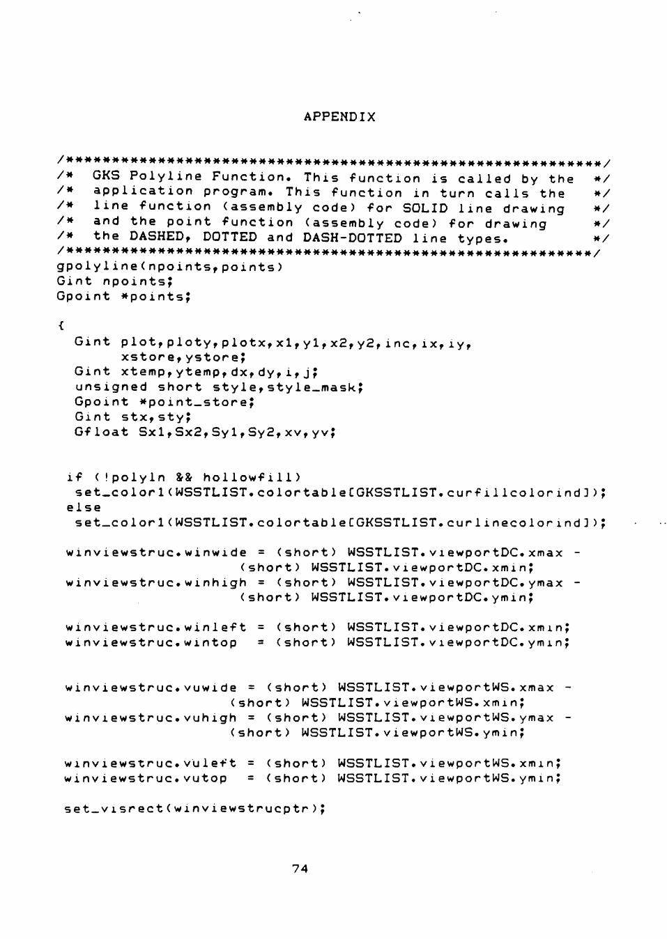
APPENDIX
/MMMMMMMMMMMMMMMMMMMMMMMMMMMMMMMMMMMMMMMMMMMMMMMMMMMMMMMMMMM/
/* GKS Polyline Function. This function is called by the */ /* application program. This function in turn calls the */ /* line function (assembly code) for SOLID line drawing */ /* and the point function (assembly code) for drawing */ /* the DASHED, DOTTED and DASH-DOTTED line types. */
gpolyline(npoints,points) Gint npoints; Gpoint *points^
Gint plot,ploty,plotx,xl,yl,x2,y2,inc,ix,iy, xstore,ystore;
Gint xtemp,ytemp,dx,dy,i,j; unsigned short style,style_mask; Gpoint *point_storeJ Gint stx,sty; Gfloat Sxl,Sx2,Syl,Sy2,xv,yv;
if (Ipolyln && hollowfill) set_colorl(WSSTLIST.colortable[GKSSTLIST.curfi1Icolorind3);
else set_color 1(WSSTLIST.colortable[GKSSTLIST.cur 1inecolorind3);
winviewstruc.winwide = (short) WSSTLIST.viewportDC.xmax -(short) WSSTLIST.viewportDC.xmin;
winviewstruc.winhigh = (short) WSSTLIST.viewportDC.ymax -(short) WSSTLIST.viewportDC.ymin;
winviewstruc.winleft = (short) WSSTLIST.viewportDC.xminj winviewstruc.wintop = (short) WSSTLIST.viewportDC.yminJ
winviewstruc.vuwide = (short) WSSTLIST.viewportWS.xmax (short) WSSTLIST.viewportWS.xmin;
winviewstruc.vuhigh = (short) WSSTLIST.viewportWS.ymax (short) WSSTLIST.viewportWS.ymin;
winviewstruc.vu1 eft = (short) WSSTLIST.viewportWS.xminJ winviewstruc.vutop = (short) WSSTLIST.viewportWS.yminj
set_visrect(winviewstrucptr);
74
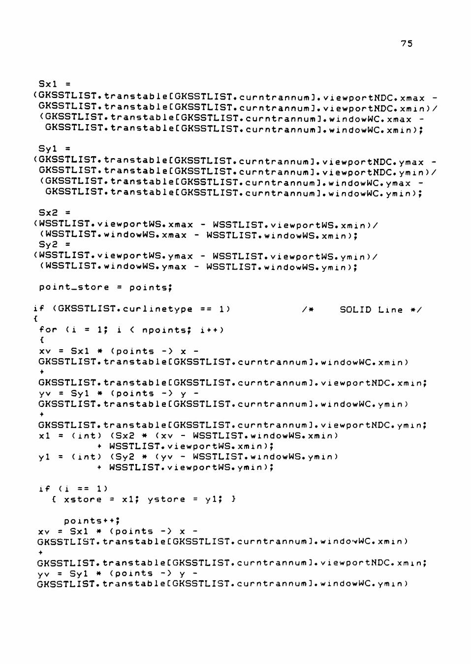
75
Sxl =
(GKSSTLIST.transtabie[GKSSTLIST.curntrannum3.viewportNDC. xmax -GKSSTLIST.transtable[GKSSTLIST.curntrannum3.VIewportNDC.xmin)/ (GKSSTLIST.transtable[GKSSTLIST.curntrannum3.windowWC.xmax -GKSSTLIST.transtable[GKSSTLIST.curntrannum3.windowWC.xmin);
Syl =
(GKSSTLIST.transtabie[GKSSTLIST.curntrannum3.viewportNDC. ymax -GKSSTLIST.transtable[GKSSTLIST.curntrannum 3.viewportNDC.ymin)/ (GKSSTLIST.transtable[GKSSTLIST.curntrannum3.windowWC.ymax -GKSSTLIST.transtable[GKSSTLIST.curntrannum3.WindowWC.ymin)?
Sx2 = (WSSTLIST.viewportWS.xmax - WSSTLIST.viewportWS. xmin)/ (WSSTLIST.windowWS.xmax - WSSTLIST.windowWS. xmin); Sy2 = (WSSTLIST.ViewportWS.ymax - WSSTLIST.viewportWS. ymin)/ (WSSTLIST.WindowWS.ymax - WSSTLIST.windowWS. ymin) ;
point_store = points^
if (GKSSTLIST.curlinetype == 1) /* SOLID Line */ { for (i = i; i < npoints; i++) { XV = Sxl * (points -> X -GKSSTLIST.transtabie[GKSSTLIST.curntrannum 3.WindowWC.xmin) •
GKSSTLIST.transtabie[GKSSTLIST.curntrannum3.viewportNDC.xmin; yv = Syl * (points -> y -GKSSTLIST.transtabie[GKSSTLIST.curntrannum3.windowWC.ymin)
GKSSTLIST.transtabie[GKSSTLIST.curntrannum3.viewportNDC. ymin; xl = (int) (Sx2 * (XV - WSSTLIST.WindowWS.xmin)
•»• WSSTLIST. viewportWS. xmin ) ; yl = (int) (Sy2 * (yv - WSSTLIST.windowWS.ymin)
* WSSTLIST.viewportWS.ymin);
if (i == 1) C xstore = xi; ystore = yi; }
points*•; XV = Sxl * (points -> X -GKSSTLIST.transtabie[GKSSTLIST.curntrannum3.windowWC.xmin) •••
GKSSTLIST.transtabie[GKSSTLIST.curntrannum3.viewportNDC.xminj yv = Syl * (points -> y -GKSSTLIST.transtabie[GKSSTLIST.curntrannum3.windowWC.ymin)
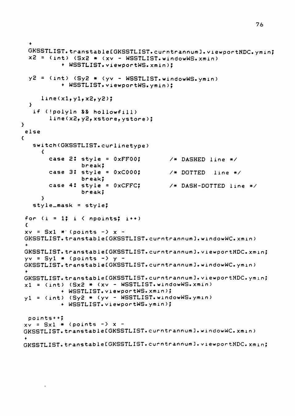
76
GKSSTLIST.transtabie[GKSSTLIST.curntrannum 3.viewportNDC.ymin; x2 = (int) (Sx2 * (xv - WSSTLIST.windowWS.xmin)
• WSSTLIST.ViewportWS.xmin);
y2 = (int) (Sy2 * (yv - WSSTLIST.windowWS.ymin) • WSSTLIST.ViewportWS.ymin);
line(xl,yl,x2,y2); } if (Ipolyln i& hollowfill)
Iine(x2,y2,xstore,ystore); } else {
switch(GKSSTLIST.cur linetype) {
case 2: style = OxFFOO; /* DASHED line */ break;
case 3: style = OxCOOO; /* DOTTED line */ break;
case 4: style = OxCFFC; /* DASH-DOTTED line */ break;
} styie_mask = style;
for (i = 1; i < npoints; i++) { XV = Sxl * (points -> X -GKSSTLIST.transtabie[GKSSTLIST.curntrannum 3.windowWC.xmin) •f
GKSSTLIST.transtabie[GKSSTLIST.curntrannum3.viewportNDC.xmm; yv = Syl * (points -> y -GKSSTLIST.transtabie[GKSSTLIST.curntrannum3.windowWC.ymin) •f
GKSSTLIST.transtabie[GKSSTLIST.curntrannum3.viewportNDC.ymin; xl = (int) (Sx2 * (XV - WSSTLIST.windowWS.xmin)
• WSSTLIST.viewportWS.xmin); yl = (int) (Sy2 * (yv - WSSTLIST.windowWS.ymin)
•»• WSSTLIST. viewportWS. ymin ) ;
points* *; XV = Sxl * (points -> X -GKSSTLIST.transtabie[GKSSTLIST.curntrannum3.windowWC.xmin) +
GKSSTLIST.transtabie[GKSSTLIST.curntrannum3.viewportNDC.xmin;
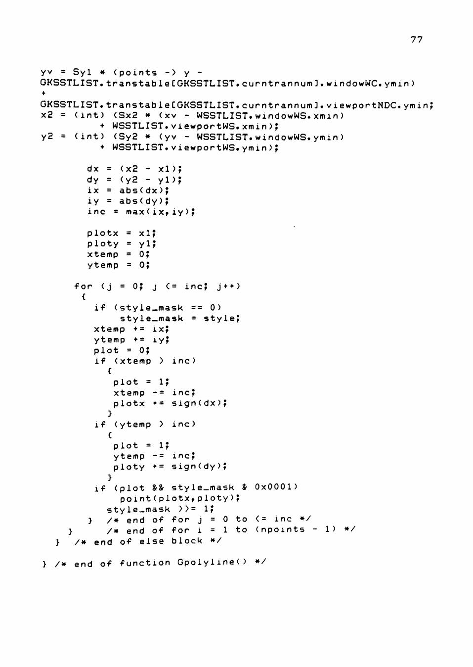
77
yv = Syl * (points -> y -GKSSTLIST.transtabie[GKSSTLIST.curntrannum3.windowWC.ymin) +
GKSSTLIST.transtable[GKSSTLIST.curntrannum 3.ViewportNDC.ymin; x2 = (int) (Sx2 * (xv - WSSTLIST.windowWS.xmin)
• WSSTLIST.ViewportWS.xmin); y2 = (int) (Sy2 * (yv - WSSTLIST.windowWS.ymin)
• WSSTLIST.ViewportWS.ymin);
dx = (x2 - xl); dy = (y2 - yl); ix = abs(dx); iy = abs(dy); inc = max(ix,iy);
plotx = xi; ploty = yi; xtemp = O; ytemp = O;
for (j = O; j <= inc; j**) {
if (style_mask == 0) style_mask = style;
xtemp •= ix; ytemp *= iy; plot = o; if (xtemp > inc)
{ plot = i; xtemp -= inc; plotx *= sign(dx); }
if (ytemp > inc) { plot = i; ytemp -= inc; ploty *= sign(dy); }
if (plot 8f& style-mask & 0x0001) point(plotx,ploty);
style-mask >>= i; } /* end of for j = 0 to <= inc */
> /* end of for i = 1 to (npoints - 1) */ } /* end of else block */
} /M end of function Gpolyline() */
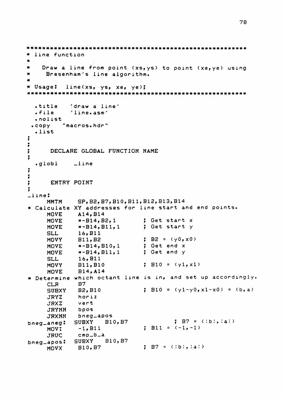
78
* line function M
* Draw a line from point (xs,ys) to point (xe,ye) using * Bresenham's line algorithm. *
* Usage: line(xs, ys, xe, ye); MMMMMMM*MMM*MMMMM**MMM*****MMMMMMMMMM*******MMMMMMMMMMMMM
.title 'draw a line'
.file 'line.asm'
.nolist .copy "macros.hdr" . list
DECLARE GLOBAL FUNCTION NAME
.globl _1ine
ENTRY POINT
.line: MMTM SP,B2,B7,B10,B11,B12,B13,B14
* Calculate XY addresses for line start and end points. MOVE A14,B14 MOVE *-B14,B2,l ; Get start x MOVE *-B14,Bll,l ; Get start y SLL 16,B11 MOVY B11,B2 ; B2 = (yO,xO) MOVE *-B14,B10,l ; Get end x MOVE *-B14,Bll,l ; Get end y SLL 16,B11 MOVY B11,B10 ; BIO = (yl,xl) MOVE B14,A14
* Determine which octant line is in, and set up accordingly. CLR B7 SUBXY B2,B10 ; BIO = (y1-yO,xl-xO) = (b,a) JRYZ horiz JRXZ vert JRYNN bpos JRXNN bneg_apos
bneg_aneg: SUBXY B10,B7 ; B7 = (:b:,:a!) MOVI -1,B11 ; Bll = (-1,-1) JRUC cmp_b_a
bneg-apos: SUBXY B10,B7 MOVX B10,B7 ; B7 = ( :b: , la! )
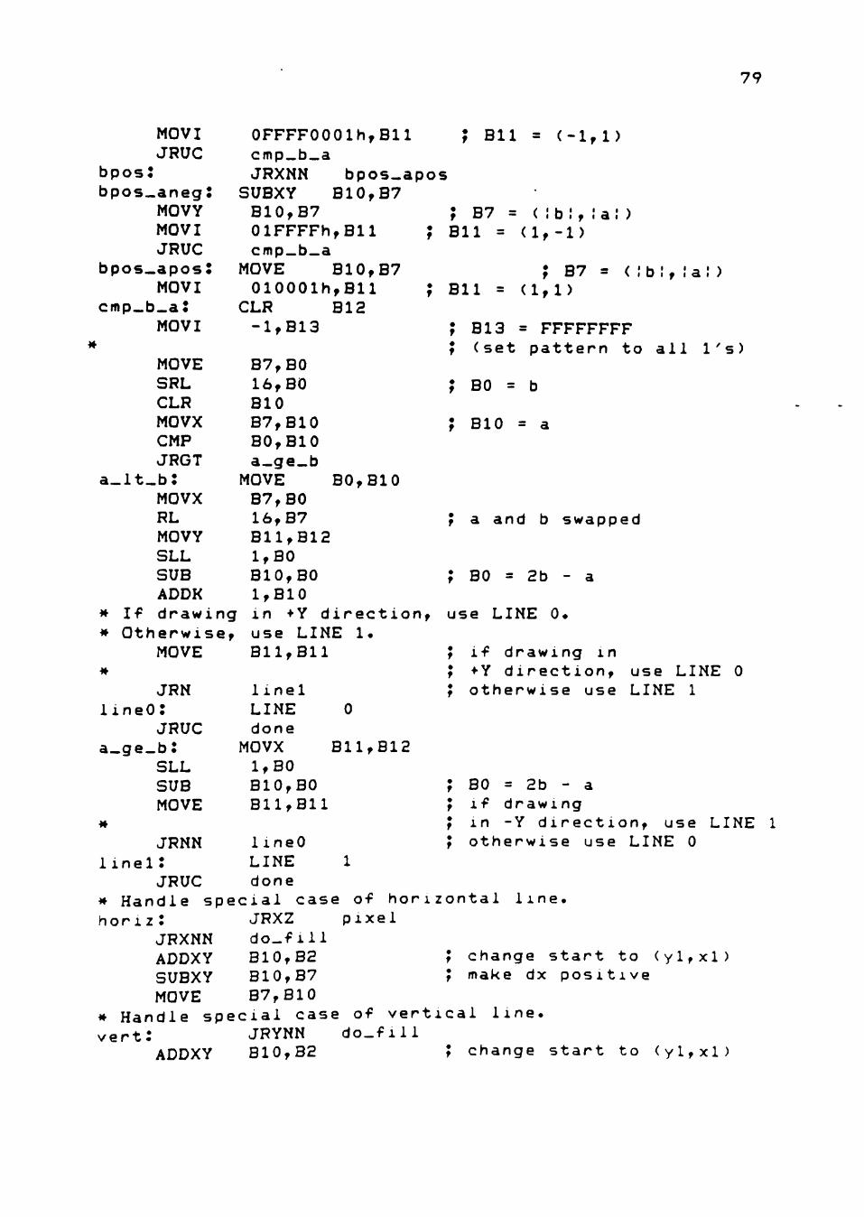
79
MOVI JRUC
bpos: bpos_aneg:
MOVY MOVI JRUC
bpos.apos: MOVI
cmp_b.a: MOVI
MOVE SRL CLR MOVX CMP JRGT
a-lt-b: MOVX RL MOVY SLL SUB ADDK
* If drawi * Otherwis
MOVE M
JRN lineO:
JRUC a_ge_b:
SLL SUB MOVE
M
JRNN linei:
JRUC * Handle s hor1z :
JRXNN ADDXY SUBXY MOVE
* Handle s vert:
ADDXY
ng e,
0FFFF0001h,Bll cmp_b_a JRXNN bpos-apos
SUBXY B10,B7 B10,B7 01FFFFh,Bll ; cmp_b_a
MOVE B10,B7 010001h,Bll ;
CLR B12 -1,B13
B7,B0 16,BO BIO B7,B10 BO,BIO a-ge_b
MOVE BO,BIO B7,B0 16,B7 B11,B12 1,B0 BIO,BO 1,B10 in ••'Y direction, use LINE 1. Bll,Bll
Bll = (-1,1)
1 inel LINE done
MOVX 1,B0 BIO,BO Bll,Bll
B11,B12
; B7 = (;bI, Bll = (1,-1)
Bll = ; B7
(1,1) = ( lb f ' a: )
B13 = FFFFFFFF (set pattern to all
BO = b
BIO = a
1 's)
a and b swapped
BO = 2b - a
use LINE 0.
if drawing in •Y direction, otherwise use
use LINE LINE 1
BO = 2b - a if drawing in -Y direction. use LINE 1
1 ineO LINE 1 done
pecial case of horizontal JRXZ pixel do_fill B10,B2 B10,B7 B7,B10
pecial case of vertical JRYNN do_fill B10,B2 ; change
otherwise use LINE 0
line.
change start to (yl,xl) make dx positive
line.
start to (y1,xl)
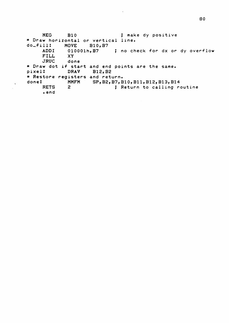
80
NEG BIO ; make dy positive * Draw horizontal or vertical line. do_fili: MOVE B10,B7
ADDI 010001h,B7 ; no check for dx or dy overflow FILL XY JRUC done
* Draw dot if start and end points are the same, pixel: DRAV B12,B2 * Restore registers and return. done: MMFM SP,B2,B7,BIO,Bl1,B12,B13,B14
RETS 2 ; Return to calling routine . end
PERMISSION TO COPY
In presenting this thesis in partial fulfillment of the
requirements for a master's degree at Texas Tech University, I agree
that the Library and my major department shall make it freely avail
able for research purposes. Permission to copy this thesis for
scholarly purposes may be granted by the Director of the Library or
my major professor. It is understood that any copying or publication
of this thesis for financial gain shall not be allowed without my
further written permission and that any user may be liable for copy
right infringement.
Disagree (Permission not granted) Agree (Permission granted)
^ J' — L.
Student's signature Student's signature
Cl -^ n J,
Date Date