Embed Size (px)
Citation preview
Adaptation Layer Translator (ALX)Design and ApplicationRuibiao Qiu, Fred Kuhns, Jerome R. Cox Jr., Craig Horn
WUCS-02-11
May 13, 2002
Department of Computer ScienceCampus Box 1045Washington UniversityOne Brookings DriveSaint Louis, MO 63130-4899
Abstract
High quality video-conferencing is an efficient tool for interactive scientific collaboration in the researchcommunity, especially for researchers separated by substantial distance. With the wide deployment of broadbandwide area IP networks such as the Internet2, there is an increasing demand for improved remote collaboration withthese networks. In order to make the high quality video-conferencing toolkits that work well on local high-speednetworks available over wide area IP networks, issues that are usually insignificant on local area networks must beconsidered. To this end, we have developed a device called an Adaptation Layer Translator (ALX) in order toaddress these issues and solve the problems associated with real-time video and audio transmission over wide areaIP networks. The ALX adopts the adaptation layer translation technique to transmit multimedia traffic on local ATMnetworks through the broadband wide area IP networks. Large buffers and careful handling of lip-synch areemployed to counter the long round-trip time and big fluctuations. The conference control protocol based on achannel rotation scheme is developed to coordinate the participants in an ALX-based conference. The ALX is alsodesigned with the capabilities to adapt to heterogenous network environments at different deployment sites.
Keywords: Adaptation layer translation, wide area IP networks, high quality video-conference.
Adaptation Layer Translator (ALX) Design and Application
Ruibiao Qiu Fred Kuhns Jerome R. Cox Jr.�
Craig Horn�
1 Introduction
1.1 High Quality Video Conferencing for Scientific Collaboration
Close collaboration among scientists has always been an important practice in the research community. Currently,as increasingly more interdisciplinary research projects are at forefront of research activities, there are increasinglymore needs for scientific collaboration among distributed researchers. Such a trend of increased collaboration isclearly demonstrated in the joint efforts of the Human Genome project and many other bioinformatics and medicalinformatics projects. Forming such interdisciplinary teams at a single institution is unlikely. Instead, partnerships areusually formed among collaborating institutions. Research teams with members separated by substantial distance willbe common in the future.
High quality video-conferencing is a promising means for such distributed scientific collaboration [Pea92, RV91,RG92, Sch96, YL94]. Researchers from different institutions can have face-to-face conversation without travelinglong distances. In addition to seeing the talking heads of the remote collaborators, the participants can exchangecomplex images with high resolution. Such images could include satellite images, computer simulations, microscopeviews, and various other complex medical images. Therefore, if we can extend high quality video-conferencing towide area networks, it would be an efficient tool for distributed scientific collaboration.
By high quality video-conferences, we mean the the video resolution should be at least 640 x 480 and at a rateof 30 frames per second. The video and audio streams in such video-conference sessions normally require morebandwidth than normal data traffic. In order to achieve an acceptable presentation quality, a minimum bandwidth fora real-time video is required. The higher the demand for quality, the higher the minimum bandwidth requirement. Forinstance, a MultiMedia Explorer (MMX) [RJE � 95] can generate video data at rates ranging from 2.5 Mb/s to 14 Mb/sfor simple blank images, and from 7.5 Mb/s to 26 Mb/s for complex color images. Because distributed scientificcollaborations frequently involve exchanging complex images, higher bandwidth is required in order to preserve thequality. Insufficient bandwidth will limit the effectiveness of the collaboration.
Currently, there are efforts to use video-conferences to assist scientific collaboration over wide area IP networks,such as the ViDeNet Project [Vid] and the AccessGrid project [Arg]. However, these video-conferencing systems arebased on ITU Recommendation H.323 [Int96b] reference model. Published as an ITU standard for video-conferencingover IP networks in 1996, the major goals of H.323 Recommendation are to achieve interoperability, manageabil-ity, platform/application/network independence, and flexibility. Therefore, video-conferencing systems based on theH.323 model have good compatibility, and seamlessly support legacy technologies such as traditional telephones,fax, cellular phones, and H.320 video-conferencing. However, because the H.323 model uses H.261 [Int90] andH.263 [Int96a] as the video codec, the video transmission rates are restricted to 1.5 Mb/s. This is insufficient to handlehigh-quality video. When there are continuous complex scenes in a video sequence, a large increase of bandwidthis required to provide video with reasonable quality. For example, although H.323 can handle MPEG-1 [ISO92]video whose maximum transmission rate is 1.5 Mb/s, it is inadequate to handle high-quality video such as MPEG-2 [ISO95] which can transmit at 15 Mb/s. Such a performance bottleneck limits the deployment of H.323-basedvideo-conferencing as a tool for scientific collaboration that requires more than just talking heads.
�Ruibiao Qiu, Fred Kuhns, and Dr. Jerome R. Cox, Jr. are with the Applied Research Laboratory, Department of Computer Science, Washington
University, Saint Louis, MO 63130. Email: � ruibiao, fredk, jrc � @arl.wustl.edu.�Craig Horn was with STS Technologies, Inc., Saint Louis, MO 63044, when this work was done. He is now with Erlang Technology, Inc.,
Saint Louis, MO 63119. Email: [email protected].
2
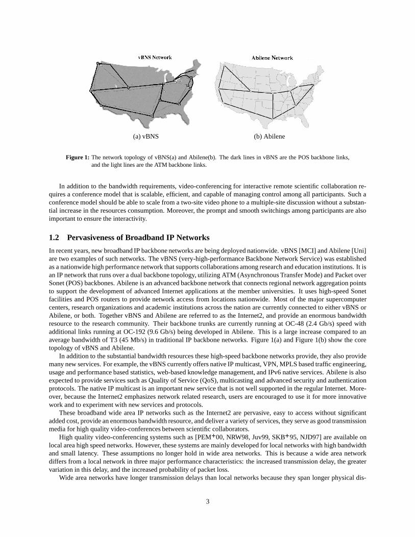
(a) vBNS (b) Abilene
Figure 1: The network topology of vBNS(a) and Abilene(b). The dark lines in vBNS are the POS backbone links,and the light lines are the ATM backbone links.
In addition to the bandwidth requirements, video-conferencing for interactive remote scientific collaboration re-quires a conference model that is scalable, efficient, and capable of managing control among all participants. Such aconference model should be able to scale from a two-site video phone to a multiple-site discussion without a substan-tial increase in the resources consumption. Moreover, the prompt and smooth switchings among participants are alsoimportant to ensure the interactivity.
1.2 Pervasiveness of Broadband IP Networks
In recent years, new broadband IP backbone networks are being deployed nationwide. vBNS [MCI] and Abilene [Uni]are two examples of such networks. The vBNS (very-high-performance Backbone Network Service) was establishedas a nationwide high performance network that supports collaborations among research and education institutions. It isan IP network that runs over a dual backbone topology, utilizing ATM (Asynchronous Transfer Mode) and Packet overSonet (POS) backbones. Abilene is an advanced backbone network that connects regional network aggregation pointsto support the development of advanced Internet applications at the member universities. It uses high-speed Sonetfacilities and POS routers to provide network access from locations nationwide. Most of the major supercomputercenters, research organizations and academic institutions across the nation are currently connected to either vBNS orAbilene, or both. Together vBNS and Abilene are referred to as the Internet2, and provide an enormous bandwidthresource to the research community. Their backbone trunks are currently running at OC-48 (2.4 Gb/s) speed withadditional links running at OC-192 (9.6 Gb/s) being developed in Abilene. This is a large increase compared to anaverage bandwidth of T3 (45 Mb/s) in traditional IP backbone networks. Figure 1(a) and Figure 1(b) show the coretopology of vBNS and Abilene.
In addition to the substantial bandwidth resources these high-speed backbone networks provide, they also providemany new services. For example, the vBNS currently offers native IP multicast, VPN, MPLS based traffic engineering,usage and performance based statistics, web-based knowledge management, and IPv6 native services. Abilene is alsoexpected to provide services such as Quality of Service (QoS), multicasting and advanced security and authenticationprotocols. The native IP multicast is an important new service that is not well supported in the regular Internet. More-over, because the Internet2 emphasizes network related research, users are encouraged to use it for more innovativework and to experiment with new services and protocols.
These broadband wide area IP networks such as the Internet2 are pervasive, easy to access without significantadded cost, provide an enormous bandwidth resource, and deliver a variety of services, they serve as good transmissionmedia for high quality video-conferences between scientific collaborators.
High quality video-conferencing systems such as [PEM � 00, NRW98, Juv99, SKB � 95, NJD97] are available onlocal area high speed networks. However, these systems are mainly developed for local networks with high bandwidthand small latency. These assumptions no longer hold in wide area networks. This is because a wide area networkdiffers from a local network in three major performance characteristics: the increased transmission delay, the greatervariation in this delay, and the increased probability of packet loss.
Wide area networks have longer transmission delays than local networks because they span longer physical dis-
3
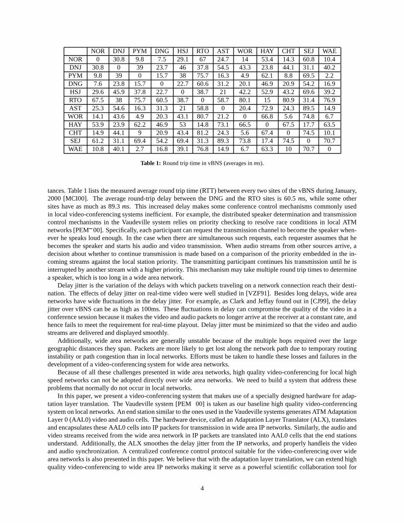
NOR DNJ PYM DNG HSJ RTO AST WOR HAY CHT SEJ WAENOR 0 30.8 9.8 7.5 29.1 67 24.7 14 53.4 14.3 60.8 10.4DNJ 30.8 0 39 23.7 46 37.8 54.5 43.3 23.8 44.1 31.1 40.2PYM 9.8 39 0 15.7 38 75.7 16.3 4.9 62.1 8.8 69.5 2.2DNG 7.6 23.8 15.7 0 22.7 60.6 31.2 20.1 46.9 20.9 54.2 16.9HSJ 29.6 45.9 37.8 22.7 0 38.7 21 42.2 52.9 43.2 69.6 39.2RTO 67.5 38 75.7 60.5 38.7 0 58.7 80.1 15 80.9 31.4 76.9AST 25.3 54.6 16.3 31.3 21 58.8 0 20.4 72.9 24.3 89.5 14.9WOR 14.1 43.6 4.9 20.3 43.1 80.7 21.2 0 66.8 5.6 74.8 6.7HAY 53.9 23.9 62.2 46.9 53 14.8 73.1 66.5 0 67.5 17.7 63.5CHT 14.9 44.1 9 20.9 43.4 81.2 24.3 5.6 67.4 0 74.5 10.1SEJ 61.2 31.1 69.4 54.2 69.4 31.3 89.3 73.8 17.4 74.5 0 70.7
WAE 10.8 40.1 2.7 16.8 39.1 76.8 14.9 6.7 63.3 10 70.7 0
Table 1: Round trip time in vBNS (averages in ms).
tances. Table 1 lists the measured average round trip time (RTT) between every two sites of the vBNS during January,2000 [MCI00]. The average round-trip delay between the DNG and the RTO sites is 60.5 ms, while some othersites have as much as 89.3 ms. This increased delay makes some conference control mechanisms commonly usedin local video-conferencing systems inefficient. For example, the distributed speaker determination and transmissioncontrol mechanisms in the Vaudeville system relies on priority checking to resolve race conditions in local ATMnetworks [PEM � 00]. Specifically, each participant can request the transmission channel to become the speaker when-ever he speaks loud enough. In the case when there are simultaneous such requests, each requester assumes that hebecomes the speaker and starts his audio and video transmission. When audio streams from other sources arrive, adecision about whether to continue transmission is made based on a comparison of the priority embedded in the in-coming streams against the local station priority. The transmitting participant continues his transmission until he isinterrupted by another stream with a higher priority. This mechanism may take multiple round trip times to determinea speaker, which is too long in a wide area network.
Delay jitter is the variation of the delays with which packets traveling on a network connection reach their desti-nation. The effects of delay jitter on real-time video were well studied in [VZF91]. Besides long delays, wide areanetworks have wide fluctuations in the delay jitter. For example, as Clark and Jeffay found out in [CJ99], the delayjitter over vBNS can be as high as 100ms. These fluctuations in delay can compromise the quality of the video in aconference session because it makes the video and audio packets no longer arrive at the receiver at a constant rate, andhence fails to meet the requirement for real-time playout. Delay jitter must be minimized so that the video and audiostreams are delivered and displayed smoothly.
Additionally, wide area networks are generally unstable because of the multiple hops required over the largegeographic distances they span. Packets are more likely to get lost along the network path due to temporary routinginstability or path congestion than in local networks. Efforts must be taken to handle these losses and failures in thedevelopment of a video-conferencing system for wide area networks.
Because of all these challenges presented in wide area networks, high quality video-conferencing for local highspeed networks can not be adopted directly over wide area networks. We need to build a system that address theseproblems that normally do not occur in local networks.
In this paper, we present a video-conferencing system that makes use of a specially designed hardware for adap-tation layer translation. The Vaudeville system [PEM � 00] is taken as our baseline high quality video-conferencingsystem on local networks. An end station similar to the ones used in the Vaudeville systems generates ATM AdaptationLayer 0 (AAL0) video and audio cells. The hardware device, called an Adaptation Layer Translator (ALX), translatesand encapsulates these AAL0 cells into IP packets for transmission in wide area IP networks. Similarly, the audio andvideo streams received from the wide area network in IP packets are translated into AAL0 cells that the end stationsunderstand. Additionally, the ALX smoothes the delay jitter from the IP networks, and properly handleis the videoand audio synchronization. A centralized conference control protocol suitable for the video-conferencing over widearea networks is also presented in this paper. We believe that with the adaptation layer translation, we can extend highquality video-conferencing to wide area IP networks making it serve as a powerful scientific collaboration tool for
4
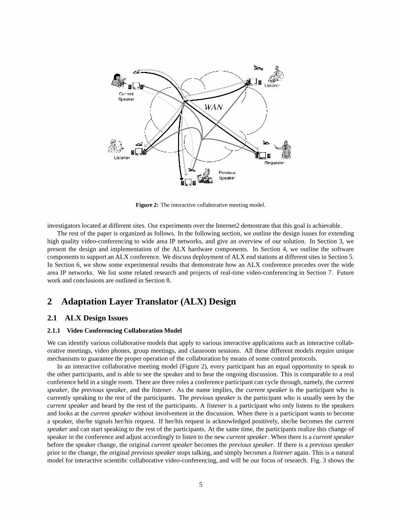
Figure 2: The interactive collaborative meeting model.
investigators located at different sites. Our experiments over the Internet2 demostrate that this goal is achievable.The rest of the paper is organized as follows. In the following section, we outline the design issues for extending
high quality video-conferencing to wide area IP networks, and give an overview of our solution. In Section 3, wepresent the design and implementation of the ALX hardware components. In Section 4, we outline the softwarecomponents to support an ALX conference. We discuss deployment of ALX end stations at different sites in Section 5.In Section 6, we show some experimental results that demonstrate how an ALX conference precedes over the widearea IP networks. We list some related research and projects of real-time video-conferencing in Section 7. Futurework and conclusions are outlined in Section 8.
2 Adaptation Layer Translator (ALX) Design
2.1 ALX Design Issues
2.1.1 Video Conferencing Collaboration Model
We can identify various collaborative models that apply to various interactive applications such as interactive collab-orative meetings, video phones, group meetings, and classroom sessions. All these different models require uniquemechanisms to guarantee the proper operation of the collaboration by means of some control protocols.
In an interactive collaborative meeting model (Figure 2), every participant has an equal opportunity to speak tothe other participants, and is able to see the speaker and to hear the ongoing discussion. This is comparable to a realconference held in a single room. There are three roles a conference participant can cycle through, namely, the currentspeaker, the previous speaker, and the listener. As the name implies, the current speaker is the participant who iscurrently speaking to the rest of the participants. The previous speaker is the participant who is usually seen by thecurrent speaker and heard by the rest of the participants. A listener is a participant who only listens to the speakersand looks at the current speaker without involvement in the discussion. When there is a participant wants to becomea speaker, she/he signals her/his request. If her/his request is acknowledged positively, she/he becomes the currentspeaker and can start speaking to the rest of the participants. At the same time, the participants realize this change ofspeaker in the conference and adjust accordingly to listen to the new current speaker. When there is a current speakerbefore the speaker change, the original current speaker becomes the previous speaker. If there is a previous speakerprior to the change, the original previous speaker stops talking, and simply becomes a listener again. This is a naturalmodel for interactive scientific collaborative video-conferencing, and will be our focus of research. Fig. 3 shows the
5
Current Speaker
Previous Speaker
Video+Audio
Audio only
Listeners
Current Speaker
Previous Speaker
Video+Audio
Audio only
Listeners
New Speaker
(a) The model with two speakers. (b) Transition when a new speaker starts.New
PreviousSpeaker Video+Audio
Audio only
Listeners
NewCurrent Speaker
(c) After all participants switch to the new speaker.
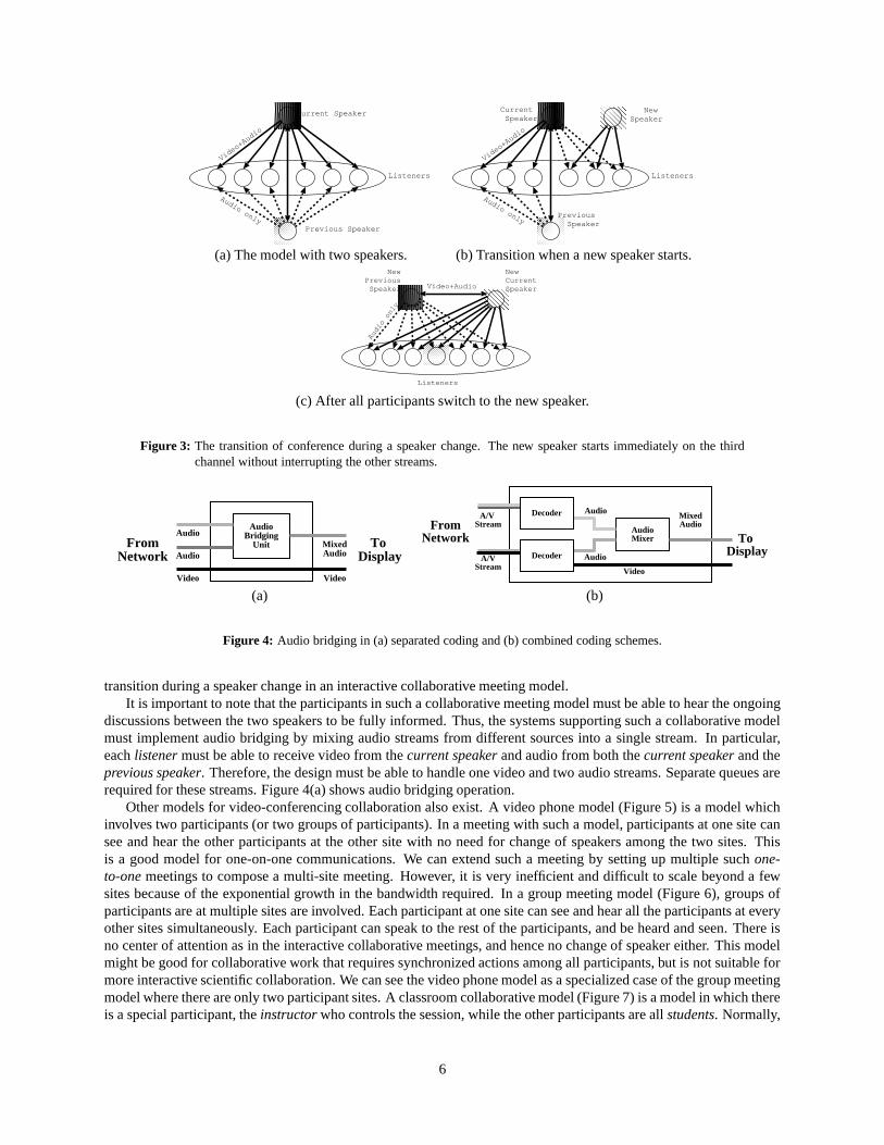
Figure 3: The transition of conference during a speaker change. The new speaker starts immediately on the thirdchannel without interrupting the other streams.
AudioBridging
UnitAudio
Audio
Video
MixedAudio
Video
FromNetwork
To Display
A/V Stream
A/VStream
MixedAudio
Video
FromNetwork To
Display
AudioMixer
Decoder Audio
AudioDecoder
(a) (b)
Figure 4: Audio bridging in (a) separated coding and (b) combined coding schemes.
transition during a speaker change in an interactive collaborative meeting model.It is important to note that the participants in such a collaborative meeting model must be able to hear the ongoing
discussions between the two speakers to be fully informed. Thus, the systems supporting such a collaborative modelmust implement audio bridging by mixing audio streams from different sources into a single stream. In particular,each listener must be able to receive video from the current speaker and audio from both the current speaker and theprevious speaker. Therefore, the design must be able to handle one video and two audio streams. Separate queues arerequired for these streams. Figure 4(a) shows audio bridging operation.
Other models for video-conferencing collaboration also exist. A video phone model (Figure 5) is a model whichinvolves two participants (or two groups of participants). In a meeting with such a model, participants at one site cansee and hear the other participants at the other site with no need for change of speakers among the two sites. Thisis a good model for one-on-one communications. We can extend such a meeting by setting up multiple such one-to-one meetings to compose a multi-site meeting. However, it is very inefficient and difficult to scale beyond a fewsites because of the exponential growth in the bandwidth required. In a group meeting model (Figure 6), groups ofparticipants are at multiple sites are involved. Each participant at one site can see and hear all the participants at everyother sites simultaneously. Each participant can speak to the rest of the participants, and be heard and seen. There isno center of attention as in the interactive collaborative meetings, and hence no change of speaker either. This modelmight be good for collaborative work that requires synchronized actions among all participants, but is not suitable formore interactive scientific collaboration. We can see the video phone model as a specialized case of the group meetingmodel where there are only two participant sites. A classroom collaborative model (Figure 7) is a model in which thereis a special participant, the instructor who controls the session, while the other participants are all students. Normally,
6
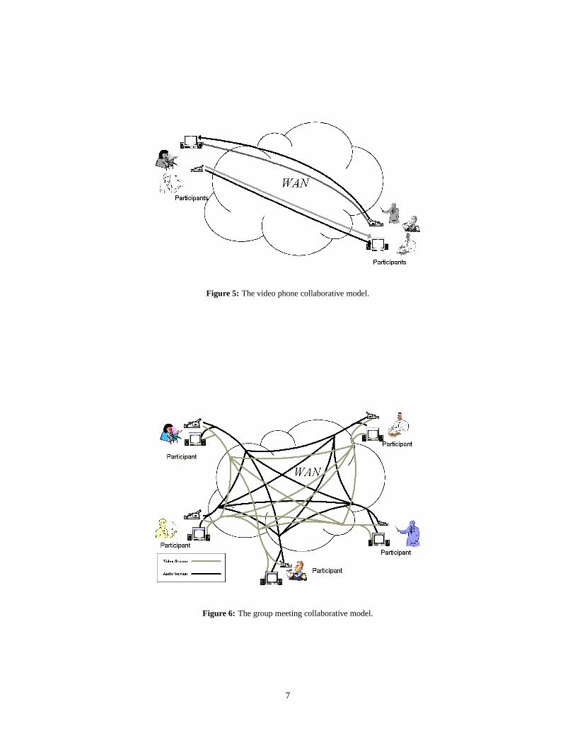
Figure 5: The video phone collaborative model.
Figure 6: The group meeting collaborative model.
7
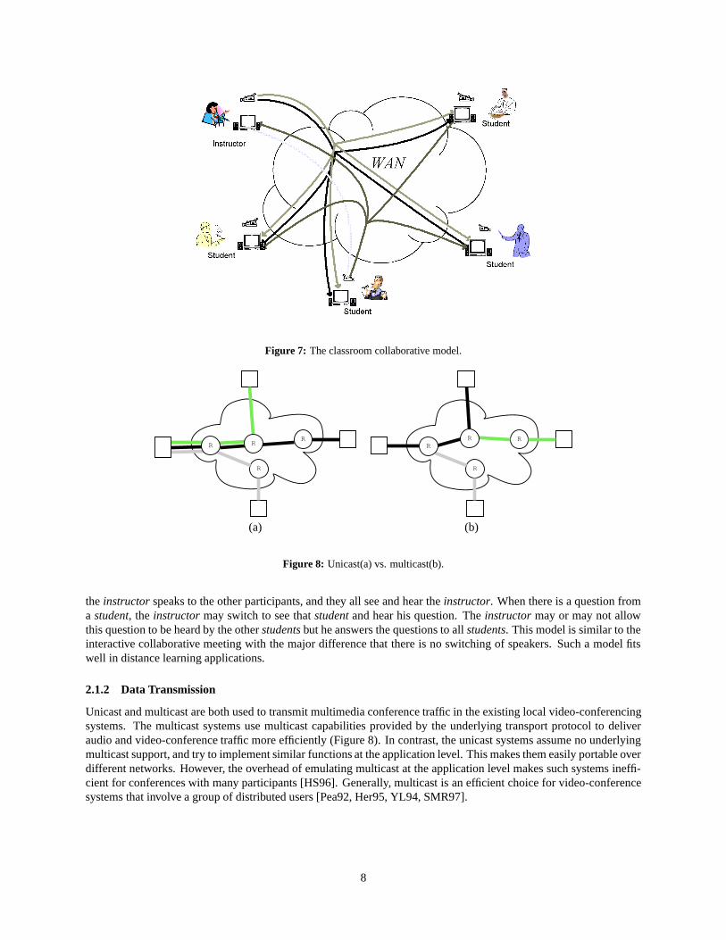
Figure 7: The classroom collaborative model.
R
RR R
R
RRR
(a) (b)
Figure 8: Unicast(a) vs. multicast(b).
the instructor speaks to the other participants, and they all see and hear the instructor. When there is a question froma student, the instructor may switch to see that student and hear his question. The instructor may or may not allowthis question to be heard by the other students but he answers the questions to all students. This model is similar to theinteractive collaborative meeting with the major difference that there is no switching of speakers. Such a model fitswell in distance learning applications.
2.1.2 Data Transmission
Unicast and multicast are both used to transmit multimedia conference traffic in the existing local video-conferencingsystems. The multicast systems use multicast capabilities provided by the underlying transport protocol to deliveraudio and video-conference traffic more efficiently (Figure 8). In contrast, the unicast systems assume no underlyingmulticast support, and try to implement similar functions at the application level. This makes them easily portable overdifferent networks. However, the overhead of emulating multicast at the application level makes such systems ineffi-cient for conferences with many participants [HS96]. Generally, multicast is an efficient choice for video-conferencesystems that involve a group of distributed users [Pea92, Her95, YL94, SMR97].
8
WANSourceDestination
RR
RR
AudioVideo
WANSourceDestination
RR
R
AudioVideo
R
(a) (b)
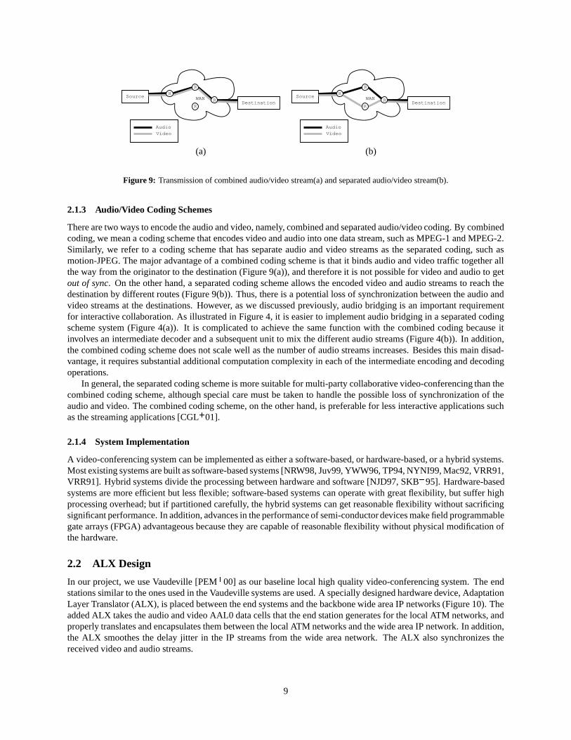
Figure 9: Transmission of combined audio/video stream(a) and separated audio/video stream(b).
2.1.3 Audio/Video Coding Schemes
There are two ways to encode the audio and video, namely, combined and separated audio/video coding. By combinedcoding, we mean a coding scheme that encodes video and audio into one data stream, such as MPEG-1 and MPEG-2.Similarly, we refer to a coding scheme that has separate audio and video streams as the separated coding, such asmotion-JPEG. The major advantage of a combined coding scheme is that it binds audio and video traffic together allthe way from the originator to the destination (Figure 9(a)), and therefore it is not possible for video and audio to getout of sync. On the other hand, a separated coding scheme allows the encoded video and audio streams to reach thedestination by different routes (Figure 9(b)). Thus, there is a potential loss of synchronization between the audio andvideo streams at the destinations. However, as we discussed previously, audio bridging is an important requirementfor interactive collaboration. As illustrated in Figure 4, it is easier to implement audio bridging in a separated codingscheme system (Figure 4(a)). It is complicated to achieve the same function with the combined coding because itinvolves an intermediate decoder and a subsequent unit to mix the different audio streams (Figure 4(b)). In addition,the combined coding scheme does not scale well as the number of audio streams increases. Besides this main disad-vantage, it requires substantial additional computation complexity in each of the intermediate encoding and decodingoperations.
In general, the separated coding scheme is more suitable for multi-party collaborative video-conferencing than thecombined coding scheme, although special care must be taken to handle the possible loss of synchronization of theaudio and video. The combined coding scheme, on the other hand, is preferable for less interactive applications suchas the streaming applications [CGL � 01].
2.1.4 System Implementation
A video-conferencing system can be implemented as either a software-based, or hardware-based, or a hybrid systems.Most existing systems are built as software-based systems [NRW98, Juv99, YWW96, TP94, NYNI99, Mac92, VRR91,VRR91]. Hybrid systems divide the processing between hardware and software [NJD97, SKB � 95]. Hardware-basedsystems are more efficient but less flexible; software-based systems can operate with great flexibility, but suffer highprocessing overhead; but if partitioned carefully, the hybrid systems can get reasonable flexibility without sacrificingsignificant performance. In addition, advances in the performance of semi-conductor devices make field programmablegate arrays (FPGA) advantageous because they are capable of reasonable flexibility without physical modification ofthe hardware.
2.2 ALX Design
In our project, we use Vaudeville [PEM � 00] as our baseline local high quality video-conferencing system. The endstations similar to the ones used in the Vaudeville systems are used. A specially designed hardware device, AdaptationLayer Translator (ALX), is placed between the end systems and the backbone wide area IP networks (Figure 10). Theadded ALX takes the audio and video AAL0 data cells that the end station generates for the local ATM networks, andproperly translates and encapsulates them between the local ATM networks and the wide area IP network. In addition,the ALX smoothes the delay jitter in the IP streams from the wide area network. The ALX also synchronizes thereceived video and audio streams.
9
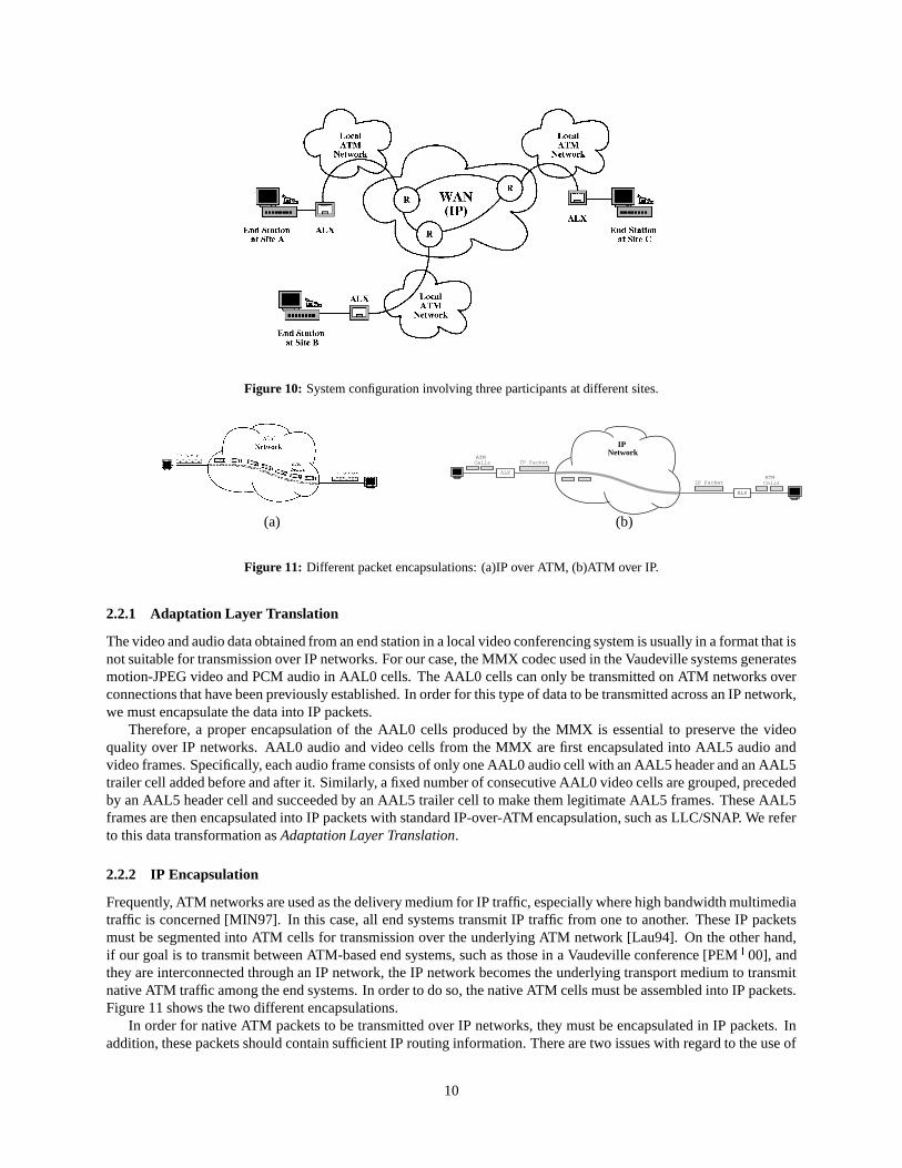
Figure 10: System configuration involving three participants at different sites.
IP Network
IP Packet
IP Packet
ALX
ALX
ATM Cells
ATM Cells
(a) (b)
Figure 11: Different packet encapsulations: (a)IP over ATM, (b)ATM over IP.
2.2.1 Adaptation Layer Translation
The video and audio data obtained from an end station in a local video conferencing system is usually in a format that isnot suitable for transmission over IP networks. For our case, the MMX codec used in the Vaudeville systems generatesmotion-JPEG video and PCM audio in AAL0 cells. The AAL0 cells can only be transmitted on ATM networks overconnections that have been previously established. In order for this type of data to be transmitted across an IP network,we must encapsulate the data into IP packets.
Therefore, a proper encapsulation of the AAL0 cells produced by the MMX is essential to preserve the videoquality over IP networks. AAL0 audio and video cells from the MMX are first encapsulated into AAL5 audio andvideo frames. Specifically, each audio frame consists of only one AAL0 audio cell with an AAL5 header and an AAL5trailer cell added before and after it. Similarly, a fixed number of consecutive AAL0 video cells are grouped, precededby an AAL5 header cell and succeeded by an AAL5 trailer cell to make them legitimate AAL5 frames. These AAL5frames are then encapsulated into IP packets with standard IP-over-ATM encapsulation, such as LLC/SNAP. We referto this data transformation as Adaptation Layer Translation.
2.2.2 IP Encapsulation
Frequently, ATM networks are used as the delivery medium for IP traffic, especially where high bandwidth multimediatraffic is concerned [MIN97]. In this case, all end systems transmit IP traffic from one to another. These IP packetsmust be segmented into ATM cells for transmission over the underlying ATM network [Lau94]. On the other hand,if our goal is to transmit between ATM-based end systems, such as those in a Vaudeville conference [PEM � 00], andthey are interconnected through an IP network, the IP network becomes the underlying transport medium to transmitnative ATM traffic among the end systems. In order to do so, the native ATM cells must be assembled into IP packets.Figure 11 shows the two different encapsulations.
In order for native ATM packets to be transmitted over IP networks, they must be encapsulated in IP packets. Inaddition, these packets should contain sufficient IP routing information. There are two issues with regard to the use of
10
Source
Destination
Leaky BucketRate
Control
WAN
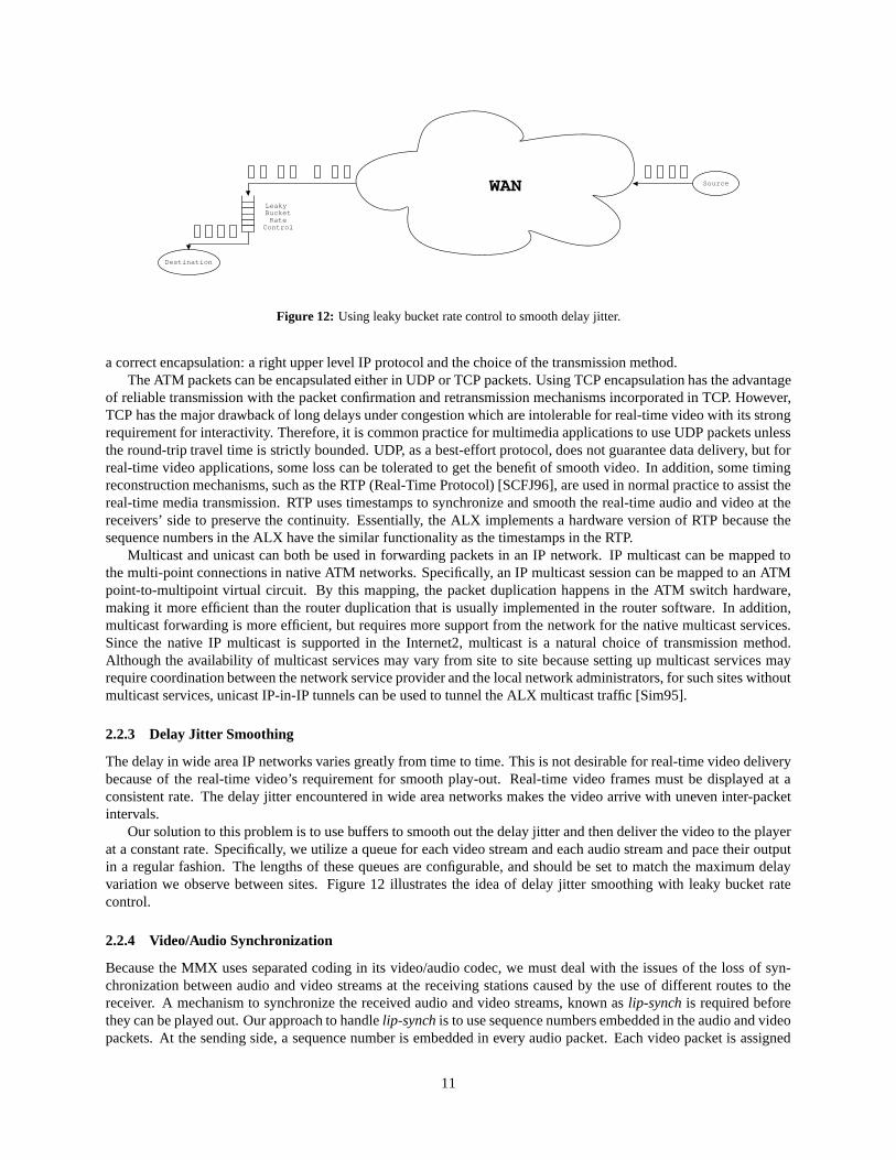
Figure 12: Using leaky bucket rate control to smooth delay jitter.
a correct encapsulation: a right upper level IP protocol and the choice of the transmission method.The ATM packets can be encapsulated either in UDP or TCP packets. Using TCP encapsulation has the advantage
of reliable transmission with the packet confirmation and retransmission mechanisms incorporated in TCP. However,TCP has the major drawback of long delays under congestion which are intolerable for real-time video with its strongrequirement for interactivity. Therefore, it is common practice for multimedia applications to use UDP packets unlessthe round-trip travel time is strictly bounded. UDP, as a best-effort protocol, does not guarantee data delivery, but forreal-time video applications, some loss can be tolerated to get the benefit of smooth video. In addition, some timingreconstruction mechanisms, such as the RTP (Real-Time Protocol) [SCFJ96], are used in normal practice to assist thereal-time media transmission. RTP uses timestamps to synchronize and smooth the real-time audio and video at thereceivers’ side to preserve the continuity. Essentially, the ALX implements a hardware version of RTP because thesequence numbers in the ALX have the similar functionality as the timestamps in the RTP.
Multicast and unicast can both be used in forwarding packets in an IP network. IP multicast can be mapped tothe multi-point connections in native ATM networks. Specifically, an IP multicast session can be mapped to an ATMpoint-to-multipoint virtual circuit. By this mapping, the packet duplication happens in the ATM switch hardware,making it more efficient than the router duplication that is usually implemented in the router software. In addition,multicast forwarding is more efficient, but requires more support from the network for the native multicast services.Since the native IP multicast is supported in the Internet2, multicast is a natural choice of transmission method.Although the availability of multicast services may vary from site to site because setting up multicast services mayrequire coordination between the network service provider and the local network administrators, for such sites withoutmulticast services, unicast IP-in-IP tunnels can be used to tunnel the ALX multicast traffic [Sim95].
2.2.3 Delay Jitter Smoothing
The delay in wide area IP networks varies greatly from time to time. This is not desirable for real-time video deliverybecause of the real-time video’s requirement for smooth play-out. Real-time video frames must be displayed at aconsistent rate. The delay jitter encountered in wide area networks makes the video arrive with uneven inter-packetintervals.
Our solution to this problem is to use buffers to smooth out the delay jitter and then deliver the video to the playerat a constant rate. Specifically, we utilize a queue for each video stream and each audio stream and pace their outputin a regular fashion. The lengths of these queues are configurable, and should be set to match the maximum delayvariation we observe between sites. Figure 12 illustrates the idea of delay jitter smoothing with leaky bucket ratecontrol.
2.2.4 Video/Audio Synchronization
Because the MMX uses separated coding in its video/audio codec, we must deal with the issues of the loss of syn-chronization between audio and video streams at the receiving stations caused by the use of different routes to thereceiver. A mechanism to synchronize the received audio and video streams, known as lip-synch is required beforethey can be played out. Our approach to handle lip-synch is to use sequence numbers embedded in the audio and videopackets. At the sending side, a sequence number is embedded in every audio packet. Each video packet is assigned
11
HTIDO/E SUNI SUNI O/E
Inserter
Deleter
ToNetwork
ToMMX
CellInput
DRAM
LipSynch
CellOutput
CellInput
H/T CRC
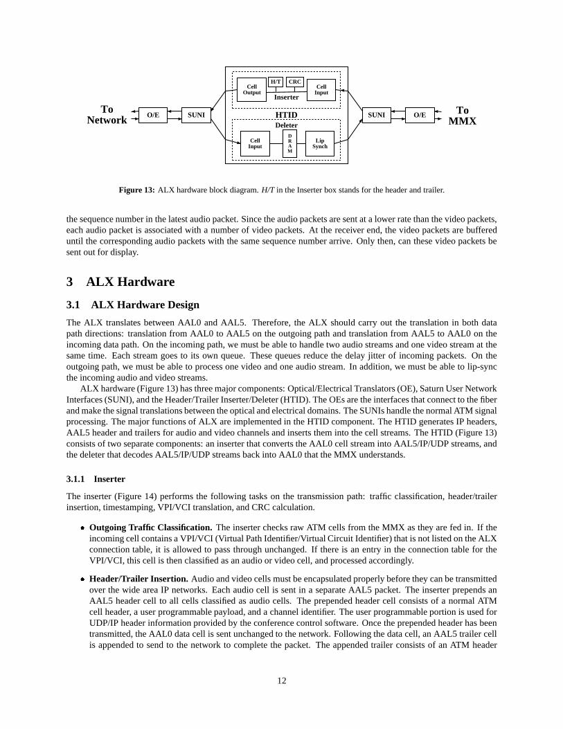
Figure 13: ALX hardware block diagram. H/T in the Inserter box stands for the header and trailer.
the sequence number in the latest audio packet. Since the audio packets are sent at a lower rate than the video packets,each audio packet is associated with a number of video packets. At the receiver end, the video packets are buffereduntil the corresponding audio packets with the same sequence number arrive. Only then, can these video packets besent out for display.
3 ALX Hardware
3.1 ALX Hardware Design
The ALX translates between AAL0 and AAL5. Therefore, the ALX should carry out the translation in both datapath directions: translation from AAL0 to AAL5 on the outgoing path and translation from AAL5 to AAL0 on theincoming data path. On the incoming path, we must be able to handle two audio streams and one video stream at thesame time. Each stream goes to its own queue. These queues reduce the delay jitter of incoming packets. On theoutgoing path, we must be able to process one video and one audio stream. In addition, we must be able to lip-syncthe incoming audio and video streams.
ALX hardware (Figure 13) has three major components: Optical/Electrical Translators (OE), Saturn User NetworkInterfaces (SUNI), and the Header/Trailer Inserter/Deleter (HTID). The OEs are the interfaces that connect to the fiberand make the signal translations between the optical and electrical domains. The SUNIs handle the normal ATM signalprocessing. The major functions of ALX are implemented in the HTID component. The HTID generates IP headers,AAL5 header and trailers for audio and video channels and inserts them into the cell streams. The HTID (Figure 13)consists of two separate components: an inserter that converts the AAL0 cell stream into AAL5/IP/UDP streams, andthe deleter that decodes AAL5/IP/UDP streams back into AAL0 that the MMX understands.
3.1.1 Inserter
The inserter (Figure 14) performs the following tasks on the transmission path: traffic classification, header/trailerinsertion, timestamping, VPI/VCI translation, and CRC calculation.
� Outgoing Traffic Classification. The inserter checks raw ATM cells from the MMX as they are fed in. If theincoming cell contains a VPI/VCI (Virtual Path Identifier/Virtual Circuit Identifier) that is not listed on the ALXconnection table, it is allowed to pass through unchanged. If there is an entry in the connection table for theVPI/VCI, this cell is then classified as an audio or video cell, and processed accordingly.
� Header/Trailer Insertion. Audio and video cells must be encapsulated properly before they can be transmittedover the wide area IP networks. Each audio cell is sent in a separate AAL5 packet. The inserter prepends anAAL5 header cell to all cells classified as audio cells. The prepended header cell consists of a normal ATMcell header, a user programmable payload, and a channel identifier. The user programmable portion is used forUDP/IP header information provided by the conference control software. Once the prepended header has beentransmitted, the AAL0 data cell is sent unchanged to the network. Following the data cell, an AAL5 trailer cellis appended to send to the network to complete the packet. The appended trailer consists of an ATM header
12
Timestamp
InsertAAL5 HeaderAAL5 TrailerUDP Header
InsertAAL5 HeaderAAL5 TrailerUDP Header
Audio Cell
Video Cell
Other Cell
AAL5 CRCGenerator
AAL5 CRCGenerator
Audio Cell T AH
CRC
CRC
Cell
Output
UH
Video Cell T AHUH
Audio Cell T AHUH
Video Cell T AHUH
ToNetwork
FromMMX
ATM
Header
Classification
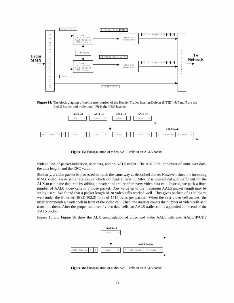
Figure 14: The block diagram of the Inserter portion of the Header/Trailer Inserter/Deleter (HTID). AH and T are theAAL5 header and trailer, and UH is the UDP header.
Video Video Video Video...
Video Video Video Video... HIP HeaderUDP Header0H0AAL5 Trailer
AAL5 Header
AAL0 cell AAL0 cell AAL0 cell AAL0 cell
H H H H
H H H H
Figure 15: Encapsulation of video AAL0 cells in an AAL5 packet.
with an end-of-packet indication, user data, and an AAL5 trailer. The AAL5 trailer consist of some user data,the data length, and the CRC value.
Similarly, a video packet is processed in much the same way as described above. However, since the incomingMMX video is a variable rate source which can peak at over 50 Mb/s, it is impractical and inefficient for theALX to triple the data rate by adding a header and trailer after every video data cell. Instead, we pack a fixednumber of AAL0 video cells in a video packet. Any value up to the maximum AAL5 packet length may beset by users. We found that a packet length of 20 video cells worked well. This gives packets of 1166 bytes,well under the Ethernet (IEEE 802.3) limit of 1518 bytes per packet. When the first video cell arrives, theinserter prepends a header cell in front of the video cell. Then, the inserter counts the number of video cells as ittransmits them. After the proper number of video data cells, an AAL5 trailer cell is appended at the end of theAAL5 packet.
Figure 15 and Figure 16 show the ALX encapsulation of video and audio AAL0 cells into AAL5/IP/UDP
Audio
IP HeaderUDP Header0HAAL5 Trailer
AAL5 Header
AAL0 cell
Audio
H
HH0
Figure 16: Encapsulation of audio AAL0 cells in an AAL5 packet.
13
Timestamp
Audio AudioAudio
Video
Audio
VideoVideoVideo
N+1
N+1
N N-1
Video N+1 Video N+1 Video N Video N Video N Video N-1
ALXMMX
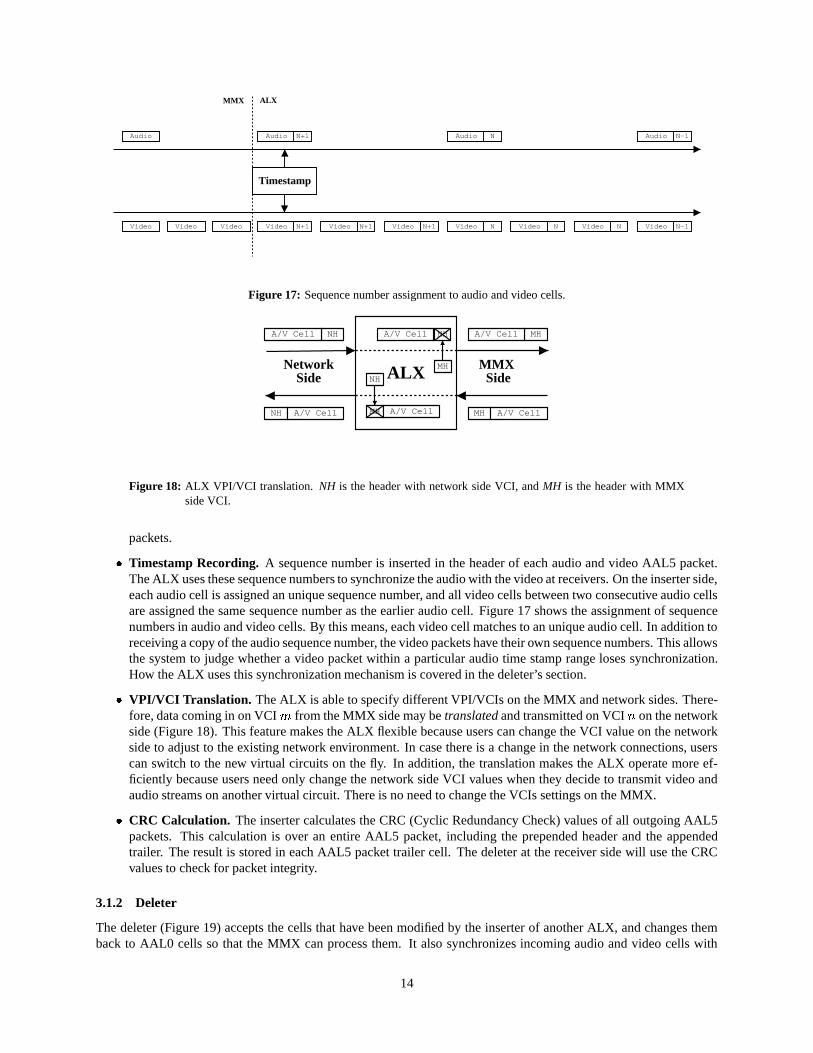
Figure 17: Sequence number assignment to audio and video cells.
ALX MH
NH
NHA/V Cell
NH A/V Cell
MHA/V Cell
MH A/V Cell
NHA/V Cell
MH A/V Cell
MMX Side
NetworkSide
Figure 18: ALX VPI/VCI translation. NH is the header with network side VCI, and MH is the header with MMXside VCI.
packets.
� Timestamp Recording. A sequence number is inserted in the header of each audio and video AAL5 packet.The ALX uses these sequence numbers to synchronize the audio with the video at receivers. On the inserter side,each audio cell is assigned an unique sequence number, and all video cells between two consecutive audio cellsare assigned the same sequence number as the earlier audio cell. Figure 17 shows the assignment of sequencenumbers in audio and video cells. By this means, each video cell matches to an unique audio cell. In addition toreceiving a copy of the audio sequence number, the video packets have their own sequence numbers. This allowsthe system to judge whether a video packet within a particular audio time stamp range loses synchronization.How the ALX uses this synchronization mechanism is covered in the deleter’s section.
� VPI/VCI Translation. The ALX is able to specify different VPI/VCIs on the MMX and network sides. There-fore, data coming in on VCI � from the MMX side may be translated and transmitted on VCI � on the networkside (Figure 18). This feature makes the ALX flexible because users can change the VCI value on the networkside to adjust to the existing network environment. In case there is a change in the network connections, userscan switch to the new virtual circuits on the fly. In addition, the translation makes the ALX operate more ef-ficiently because users need only change the network side VCI values when they decide to transmit video andaudio streams on another virtual circuit. There is no need to change the VCIs settings on the MMX.
� CRC Calculation. The inserter calculates the CRC (Cyclic Redundancy Check) values of all outgoing AAL5packets. This calculation is over an entire AAL5 packet, including the prepended header and the appendedtrailer. The result is stored in each AAL5 packet trailer cell. The deleter at the receiver side will use the CRCvalues to check for packet integrity.
3.1.2 Deleter
The deleter (Figure 19) accepts the cells that have been modified by the inserter of another ALX, and changes themback to AAL0 cells so that the MMX can process them. It also synchronizes incoming audio and video cells with
14
ATM
Header
Classification
CRCCheck
CRCCheck
Lip
Synch
CRC
CRC T
T
Audio Cell
Video Cell
Audio Cell T
T Video Cell H
H H
H
T Audio Cell
T Video Cell
Video Cell Video Cell Audio Cell Video Cell Video Cell Audio Cell
Delay Adjustment
Delay Adjustment
Timestamp = N+1 Timestamp = N
VideoDRAMBuffer
AudioDRAMBuffer
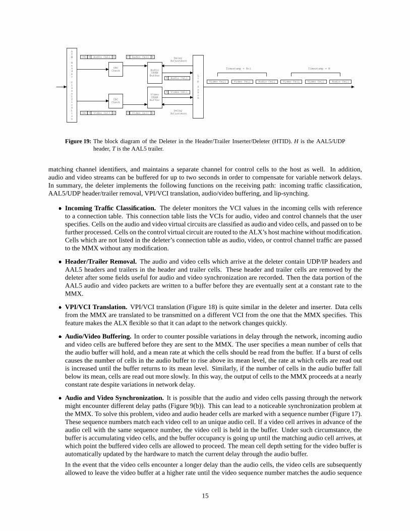
Figure 19: The block diagram of the Deleter in the Header/Trailer Inserter/Deleter (HTID). H is the AAL5/UDPheader, T is the AAL5 trailer.
matching channel identifiers, and maintains a separate channel for control cells to the host as well. In addition,audio and video streams can be buffered for up to two seconds in order to compensate for variable network delays.In summary, the deleter implements the following functions on the receiving path: incoming traffic classification,AAL5/UDP header/trailer removal, VPI/VCI translation, audio/video buffering, and lip-synching.
� Incoming Traffic Classification. The deleter monitors the VCI values in the incoming cells with referenceto a connection table. This connection table lists the VCIs for audio, video and control channels that the userspecifies. Cells on the audio and video virtual circuits are classified as audio and video cells, and passed on to befurther processed. Cells on the control virtual circuit are routed to the ALX’s host machine without modification.Cells which are not listed in the deleter’s connection table as audio, video, or control channel traffic are passedto the MMX without any modification.
� Header/Trailer Removal. The audio and video cells which arrive at the deleter contain UDP/IP headers andAAL5 headers and trailers in the header and trailer cells. These header and trailer cells are removed by thedeleter after some fields useful for audio and video synchronization are recorded. Then the data portion of theAAL5 audio and video packets are written to a buffer before they are eventually sent at a constant rate to theMMX.
� VPI/VCI Translation. VPI/VCI translation (Figure 18) is quite similar in the deleter and inserter. Data cellsfrom the MMX are translated to be transmitted on a different VCI from the one that the MMX specifies. Thisfeature makes the ALX flexible so that it can adapt to the network changes quickly.
� Audio/Video Buffering. In order to counter possible variations in delay through the network, incoming audioand video cells are buffered before they are sent to the MMX. The user specifies a mean number of cells thatthe audio buffer will hold, and a mean rate at which the cells should be read from the buffer. If a burst of cellscauses the number of cells in the audio buffer to rise above its mean level, the rate at which cells are read outis increased until the buffer returns to its mean level. Similarly, if the number of cells in the audio buffer fallbelow its mean, cells are read out more slowly. In this way, the output of cells to the MMX proceeds at a nearlyconstant rate despite variations in network delay.
� Audio and Video Synchronization. It is possible that the audio and video cells passing through the networkmight encounter different delay paths (Figure 9(b)). This can lead to a noticeable synchronization problem atthe MMX. To solve this problem, video and audio header cells are marked with a sequence number (Figure 17).These sequence numbers match each video cell to an unique audio cell. If a video cell arrives in advance of theaudio cell with the same sequence number, the video cell is held in the buffer. Under such circumstance, thebuffer is accumulating video cells, and the buffer occupancy is going up until the matching audio cell arrives, atwhich point the buffered video cells are allowed to proceed. The mean cell depth setting for the video buffer isautomatically updated by the hardware to match the current delay through the audio buffer.
In the event that the video cells encounter a longer delay than the audio cells, the video cells are subsequentlyallowed to leave the video buffer at a higher rate until the video sequence number matches the audio sequence
15
number. In this way, the audio and video buffers can be adjusted to be in synchronization no matter whichchannel has the higher delay.
3.1.3 Implementation
The ALX was implemented on a single full-sized ISA bus card. The state machines for controlling the AAL0 to AAL5conversion are contained in an Altera 10K30 FPGA using approximately 30,000 gates of logic. The AAL5 to AAL0conversion of the deleter was implemented in two Altera FPGAs, a 10K50 and a 10K100, using approximately 120,000gates of logic. The audio and video receiver buffers consist of four 64Kx32-bit SRAMs by Cypress semiconductor.
4 ALX Software
4.1 ALX Device Driver
As the ALX hardware is implemented as a PC ISA card, user level software can fully configure the ALX hardwarethrough a Linux device driver for a character device. The FPGAs are programmed over the ISA bus at boot, rather thanvia EPROM to allow for easier reconfiguration during the project debugging. The ALX device driver is implementedas a kernel loadable module. There is no substantial data exchange between user software and the ALX hardware,only the configuration information. User level applications access the ALX hardware as a normal character device,which permits operations such as open, close and write. The configuration commands are formatted strings written tothe ALX. The device driver accepts such strings, validates them as legitimate commands, and writes the correspondingcontrol data to the appropriate registers on the ALX.
4.2 ALX Conference Control Protocol
4.2.1 Conference Control Protocol Functions
A conference control protocol is required by all conference participants to setup a conference and to coordinate withother participants to make the conference proceed smoothly. The major functions of a conference control protocolconsists of two parts: floor control and session control.
A conference session�
can be described as a four-tuple�������������� ��������
.��������� �
is the set of participants,and
is the set of the channels that can be used.�� ����
and�������
are the current and previous speaker. The floorcontrol mechanism can be seen as a function � � �"!# that binds a participant that intends to become the speakerto a usable channel. The session control keeps
�up to date to reflect the current participants, maintains connectivity,
and provides session state information.
� Floor Control. The floor refers to a mutually exclusive permission that is granted dynamically while resolvingrace conditions and guaranteeing fair and deadlock-free resource access. Floor control allows users of networkedmultimedia applications, such as video-conferencing, to utilize and share resources without conflicts. Floorcontrol protocols add an access discipline to such environments that allows the resolution of race conditionson shared resources. Dommel and Garcia-Luna-Aceves [DGLA97] presented a general framework for floorcontrol protocol. They outlined the design issues of floor control protocols in [DGLA95]. Dommel [Dom98]compared various floor control protocols for collaborative multimedia environments, and found out that floorcontrol protocols that are based on multicast offer the best efficiency and scalability.
For our interactive collaborative video-conferencing applications, the resources that require mutually exclusiveaccess are the channels for audio and video streams transmission. We must prevent multiple sources fromtransmitting on the same channel simultaneously because these transmission conflicts result in unviewable videoand unintelligible audio. The function of our floor control protocol is to provide mutual exclusion for concurrentaccess to the shared transmission channels among all conference participants according to the chosen servicepolicy. Therefore, a participant is requesting the floor when he requests to become a speaker. Similarly, whenhis request is acknowledged, he is granted the floor. In our conference model, when a participant requests thefloor, the floor control mechanism must make sure the transmission channel he is about to access has no trafficfrom any other participants before the requester is granted the floor.
16
C3
C2
C1
Current
PreviousNex
t
Previous
C2
C1C3
Cur
rent N
ext
Current
C2
C1C3
Prev
ious
Next
(a) (b) (c)
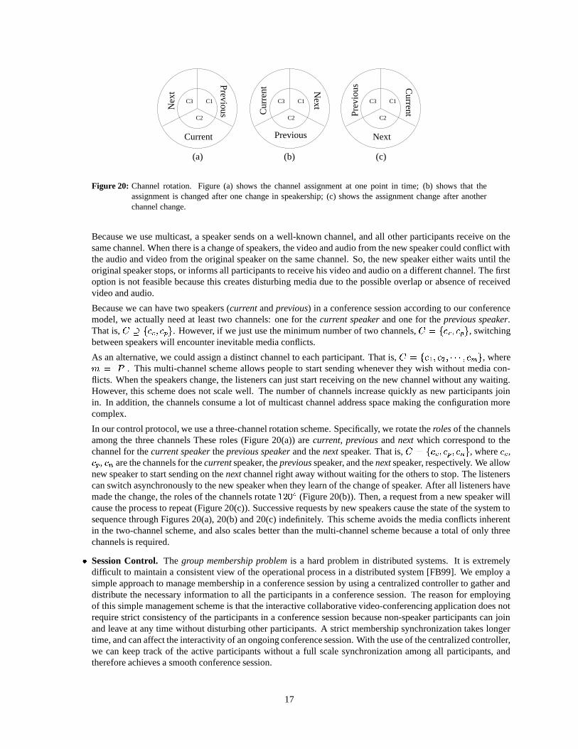
Figure 20: Channel rotation. Figure (a) shows the channel assignment at one point in time; (b) shows that theassignment is changed after one change in speakership; (c) shows the assignment change after anotherchannel change.
Because we use multicast, a speaker sends on a well-known channel, and all other participants receive on thesame channel. When there is a change of speakers, the video and audio from the new speaker could conflict withthe audio and video from the original speaker on the same channel. So, the new speaker either waits until theoriginal speaker stops, or informs all participants to receive his video and audio on a different channel. The firstoption is not feasible because this creates disturbing media due to the possible overlap or absence of receivedvideo and audio.
Because we can have two speakers (current and previous) in a conference session according to our conferencemodel, we actually need at least two channels: one for the current speaker and one for the previous speaker.That is,
����� �� � ���. However, if we just use the minimum number of two channels,
� ��� � � ���, switching
between speakers will encounter inevitable media conflicts.
As an alternative, we could assign a distinct channel to each participant. That is, � ���� � �� � � ��� � ��� �
, where� ��� ���
. This multi-channel scheme allows people to start sending whenever they wish without media con-flicts. When the speakers change, the listeners can just start receiving on the new channel without any waiting.However, this scheme does not scale well. The number of channels increase quickly as new participants joinin. In addition, the channels consume a lot of multicast channel address space making the configuration morecomplex.
In our control protocol, we use a three-channel rotation scheme. Specifically, we rotate the roles of the channelsamong the three channels These roles (Figure 20(a)) are current, previous and next which correspond to thechannel for the current speaker the previous speaker and the next speaker. That is,
� ��� � � � � ��� �, where
� ,� �
,���
are the channels for the current speaker, the previous speaker, and the next speaker, respectively. We allownew speaker to start sending on the next channel right away without waiting for the others to stop. The listenerscan switch asynchronously to the new speaker when they learn of the change of speaker. After all listeners havemade the change, the roles of the channels rotate ������ (Figure 20(b)). Then, a request from a new speaker willcause the process to repeat (Figure 20(c)). Successive requests by new speakers cause the state of the system tosequence through Figures 20(a), 20(b) and 20(c) indefinitely. This scheme avoids the media conflicts inherentin the two-channel scheme, and also scales better than the multi-channel scheme because a total of only threechannels is required.
� Session Control. The group membership problem is a hard problem in distributed systems. It is extremelydifficult to maintain a consistent view of the operational process in a distributed system [FB99]. We employ asimple approach to manage membership in a conference session by using a centralized controller to gather anddistribute the necessary information to all the participants in a conference session. The reason for employingof this simple management scheme is that the interactive collaborative video-conferencing application does notrequire strict consistency of the participants in a conference session because non-speaker participants can joinand leave at any time without disturbing other participants. A strict membership synchronization takes longertime, and can affect the interactivity of an ongoing conference session. With the use of the centralized controller,we can keep track of the active participants without a full scale synchronization among all participants, andtherefore achieves a smooth conference session.
17
Grant Pending
ClearOpen
Info Pending<GRANT ACK>[INFO w. change]
<QUENCH ACK>
<INFO ACK(from all)>[QUENCH]
<REQ (from PS)>[GRANT]
<REQ>[GRANT]
<Timeout>
<Timeout>[resend INFO]
<Timeout>[resend QUENCH]
<no PS & INFO ACK(from all)>
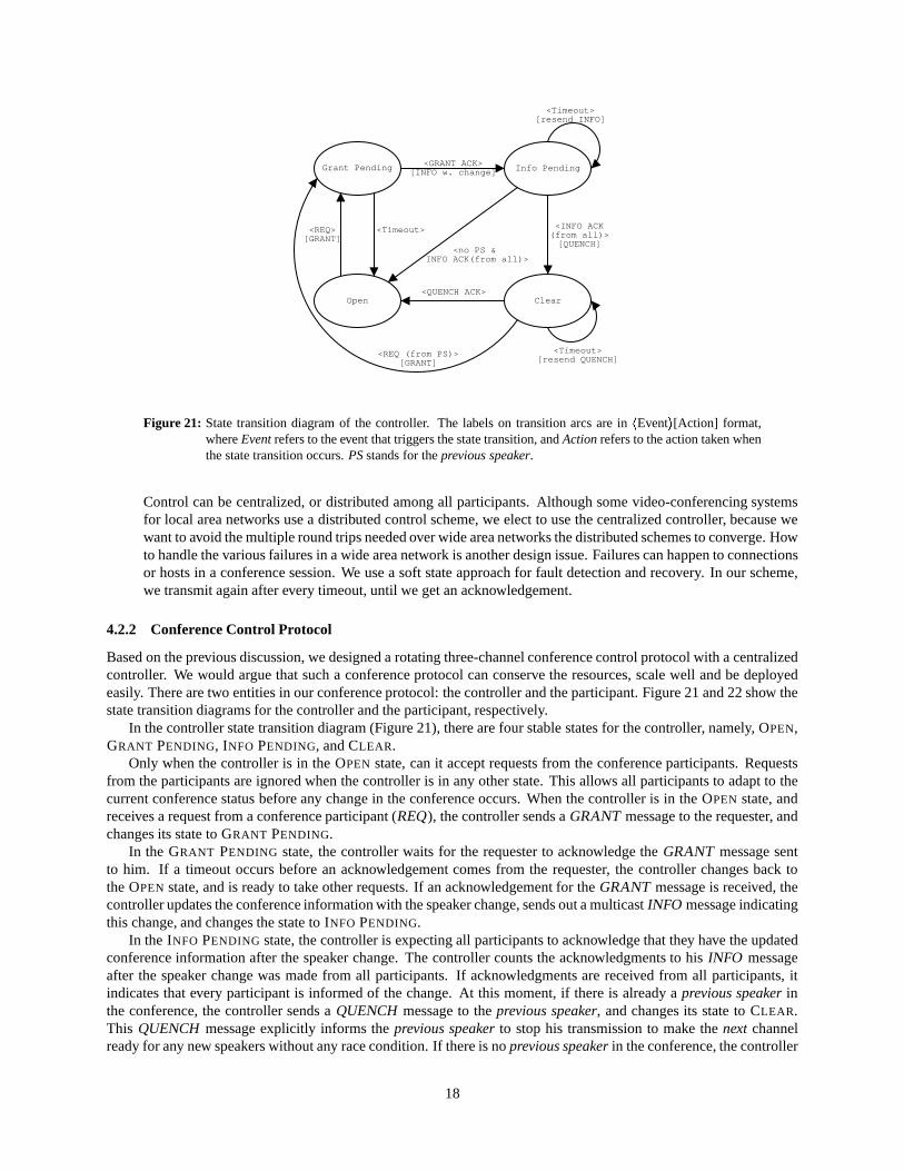
Figure 21: State transition diagram of the controller. The labels on transition arcs are in�Event � [Action] format,
where Event refers to the event that triggers the state transition, and Action refers to the action taken whenthe state transition occurs. PS stands for the previous speaker.
Control can be centralized, or distributed among all participants. Although some video-conferencing systemsfor local area networks use a distributed control scheme, we elect to use the centralized controller, because wewant to avoid the multiple round trips needed over wide area networks the distributed schemes to converge. Howto handle the various failures in a wide area network is another design issue. Failures can happen to connectionsor hosts in a conference session. We use a soft state approach for fault detection and recovery. In our scheme,we transmit again after every timeout, until we get an acknowledgement.
4.2.2 Conference Control Protocol
Based on the previous discussion, we designed a rotating three-channel conference control protocol with a centralizedcontroller. We would argue that such a conference protocol can conserve the resources, scale well and be deployedeasily. There are two entities in our conference protocol: the controller and the participant. Figure 21 and 22 show thestate transition diagrams for the controller and the participant, respectively.
In the controller state transition diagram (Figure 21), there are four stable states for the controller, namely, OPEN,GRANT PENDING, INFO PENDING, and CLEAR.
Only when the controller is in the OPEN state, can it accept requests from the conference participants. Requestsfrom the participants are ignored when the controller is in any other state. This allows all participants to adapt to thecurrent conference status before any change in the conference occurs. When the controller is in the OPEN state, andreceives a request from a conference participant (REQ ), the controller sends a GRANT message to the requester, andchanges its state to GRANT PENDING.
In the GRANT PENDING state, the controller waits for the requester to acknowledge the GRANT message sentto him. If a timeout occurs before an acknowledgement comes from the requester, the controller changes back tothe OPEN state, and is ready to take other requests. If an acknowledgement for the GRANT message is received, thecontroller updates the conference information with the speaker change, sends out a multicast INFO message indicatingthis change, and changes the state to INFO PENDING.
In the INFO PENDING state, the controller is expecting all participants to acknowledge that they have the updatedconference information after the speaker change. The controller counts the acknowledgments to his INFO messageafter the speaker change was made from all participants. If acknowledgments are received from all participants, itindicates that every participant is informed of the change. At this moment, if there is already a previous speaker inthe conference, the controller sends a QUENCH message to the previous speaker, and changes its state to CLEAR.This QUENCH message explicitly informs the previous speaker to stop his transmission to make the next channelready for any new speakers without any race condition. If there is no previous speaker in the conference, the controller
18
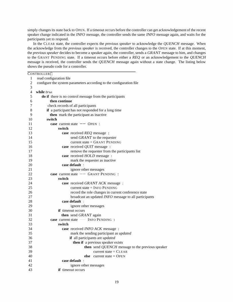
simply changes its state back to OPEN. If a timeout occurs before the controller can get acknowledgement of the recentspeaker change indicated in the INFO message, the controller sends the same INFO message again, and waits for theparticipants yet to respond.
In the CLEAR state, the controller expects the previous speaker to acknowledge the QUENCH message. Whenthe acknowledge from the previous speaker is received, the controller changes to the OPEN state. If at this moment,the previous speaker decides to become a speaker again, the controller, sends a GRANT message to him, and changesto the GRANT PENDING state. If a timeout occurs before either a REQ or an acknowledgement to the QUENCHmessage is received, the controller sends the QUENCH message again without a state change. The listing belowshows the pseudo code for a controller.
CONTROLLER� �
1 read configuration file2 configure the system parameters according to the configuration file34 while
�������
5 do if there is no control message from the participants6 then continue7 check records of all participants8 if a participant has not responded for a long time9 then mark the participant as inactive
10 switch11 case current state
� �OPEN �
12 switch13 case received REQ message �14 send GRANT to the requester15 current state = GRANT PENDING
16 case received QUIT message �17 remove the requester from the participants list18 case received HOLD message �19 mark the requester as inactive20 case default �21 ignore other messages22 case current state
� �GRANT PENDING �
23 switch24 case received GRANT ACK message �25 current state = INFO PENDING
26 record the role changes in current conference state27 broadcast an updated INFO message to all participants28 case default �29 ignore other messages30 if timeout occurs31 then send GRANT again32 case current state
� �INFO PENDING �
33 switch34 case received INFO ACK message �35 mark the sending participant as updated36 if all participants are updated37 then if a previous speaker exists38 then send QUENCH message to the previous speaker39 current state = CLEAR
40 else current state = OPEN
41 case default �42 ignore other messages43 if timeout occurs
19
CS
PSREQ Pending
Listener Hold
<GRANT>[start sending& GRANT ACK]
<INFO w. change>
<User request>[REQ]
<User request>[REQ]
<QUENCH>[QUENCH ACK]�
<INFO w. change>[stop sending]
<Timeout>[resend REQ]
Figure 22: State transition diagram of a participant. The labels are in�Event � [Action] format, where Event refers to
the event that triggers the state transition, and Action refers to the action taken when the state transitionoccurs.
44 then send the INFO again45 case current state
� �CLEAR �
46 switch47 case received REQ message �48 if the requester is the previous speaker49 then send GRANT to the sender50 current state = GRANT PENDING
51 case received QUENCH ACK message �52 current state = OPEN
53 case default �54 ignore other messages55 if timeout occurs56 then send QUENCH again57 case default �58 ignore other messages
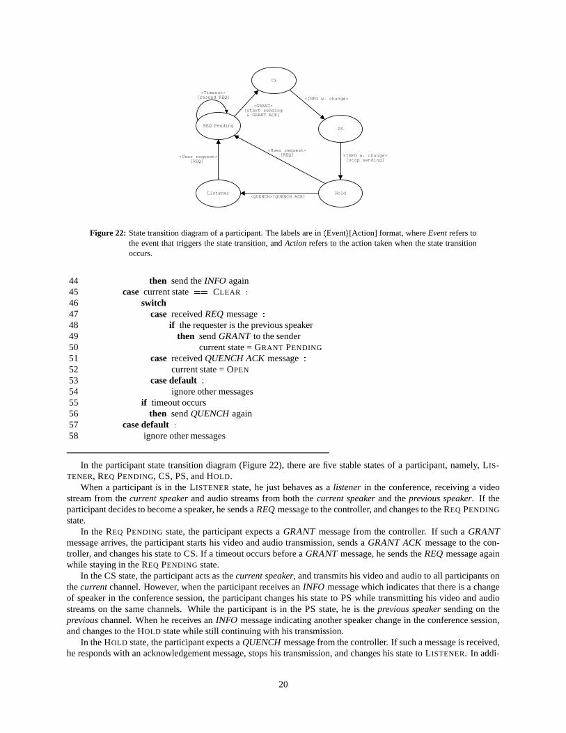
In the participant state transition diagram (Figure 22), there are five stable states of a participant, namely, LIS-TENER, REQ PENDING, CS, PS, and HOLD.
When a participant is in the LISTENER state, he just behaves as a listener in the conference, receiving a videostream from the current speaker and audio streams from both the current speaker and the previous speaker. If theparticipant decides to become a speaker, he sends a REQ message to the controller, and changes to the REQ PENDING
state.In the REQ PENDING state, the participant expects a GRANT message from the controller. If such a GRANT
message arrives, the participant starts his video and audio transmission, sends a GRANT ACK message to the con-troller, and changes his state to CS. If a timeout occurs before a GRANT message, he sends the REQ message againwhile staying in the REQ PENDING state.
In the CS state, the participant acts as the current speaker, and transmits his video and audio to all participants onthe current channel. However, when the participant receives an INFO message which indicates that there is a changeof speaker in the conference session, the participant changes his state to PS while transmitting his video and audiostreams on the same channels. While the participant is in the PS state, he is the previous speaker sending on theprevious channel. When he receives an INFO message indicating another speaker change in the conference session,and changes to the HOLD state while still continuing with his transmission.
In the HOLD state, the participant expects a QUENCH message from the controller. If such a message is received,he responds with an acknowledgement message, stops his transmission, and changes his state to LISTENER. In addi-
20
tion, the participant may choose to become the speaker again. In this case, the participant sends a REQ message to thecontroller, and changes to the REQ PENDING state. The listing below shows the pseudo code for a participant.
PARTICIPANT� �
1 read configuration file2 configure the system parameters according to the configuration file34 while
�������
5 do6 if there is an INFO message from the controller7 then send back an INFO ACK8 update the local conference information according to the INFO message9 if the user does not make any request or current state == INACTIVE
10 then continue11 determine the user request, and construct a proper control message12 switch13 case current state
� �LISTENER �
14 switch15 case the user makes a request to be speaker �16 send back a REQ to the controller17 current state = REQ PENDING
18 case the user quits �19 exit20 case the user holds �21 mark the requester as inactive22 case default �23 error “Unknown request”24 case current state
� �REQ PENDING �
25 check for GRANT from the controller26 if GRANT is received27 then current sate = CS28 start video and audio transmission29 send GRANT ACK to the controller30 else if timeout occurs31 then resend the REQ message32 case current state
� �CS �
33 if received INFO with role change34 then35 current state = PS36 case current state
� �PS �
37 if received INFO message with role change38 then current state = HOLD
39 case current state� �
HOLD �40 switch41 case the user makes a request to be speaker �42 if the requester is the previous speaker43 then send REQ to the controller44 current state = REQ PENDING
45 case received QUENCH message �46 stop video and audio transmission47 current state = LISTENER
48 case default �49 ignore other messages50 case default �
21
CS PS Requester Controller
Open
Grant Pending
Info Pending
Clear
Open
Listener
CS
PS
PS
Hold
REQ
GRANT
GRANT ACK
INFO
INFO ACK
QUENCH
QUENCH ACK
INFO
INFO INFO ACK
INFO ACK
Listener
REQ Pending
CS
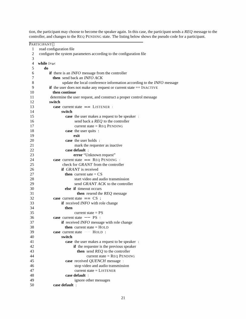
Figure 23: Timing diagram of the conference control protocol. The text boxes are the control messages, and the textnext to the vertical lines are the states.
51 ignore other messages
Figure 23 shows the timing diagram of the conference control protocol. As shown, a listener sends a REQ tothe controller in OPEN state, and waits for reply in REQ PENDING state. Without any other contending REQ, thecontroller replies with GRANT, and changes to GRANT PENDING state. Upon receipt of the GRANT, the requestersends back GRANT ACK, changes to CS state, and starts to transmit on the next channel. When the controller receivesthe GRANT ACK, a new INFO is generated corresponding to the change and transmitted onto the control channel.The controller changes to wait in the INFO PENDING state. As the new INFO is propagates to all participants, theychange their states accordingly (e.g. from CS to PS or from PS to LISTENER), switch to the new speaker, and replywith an INFO ACK. Once the controller collects all INFO ACK for the INFO, it changes back to OPEN state, and isready to take new requests.
5 ALX Deployment
5.1 Heterogenous Network Environments
When an ALX is to be deployed at a new site, we must deal with the heterogenous network environments that maybe encountered. This heterogeneity has two aspects, namely, the network infrastructure heterogeneity and networkinstability. By network infrastructure heterogeneity, we mean that each site may use different network equipment,such as routers and switches, to construct its campus network. These routers and switches from various vendorsmay provide different sets of functionalities. Sometimes, incompatible techniques are used to implement a certainfunctionality. In addition, restrictions to some functionalities often exist. For example, some ATM switches cannotprovide multipoint-to-multipoint connections, and some routers can not forward multicast IP traffic on different virtualcircuits of the same interface. Besides this functionality heterogeneity, there is also performance heterogeneity of thenetwork equipment. For instance, some routers use substantial processing resources forwarding multicast packetsbecause packet duplication is done in software.
Besides this network infrastructure heterogeneity problem, the network topology between the end points and theconnections at each site may change from time to time. The ALX system has to adapt to the existing network connec-tions and topologies.
Additionally, although multicast services are available in wide area networks, multicast support in the wide areanetworks is generally not stable, and involves coordination of efforts from the network management. In particular,when there are multiple wide area network backbones involved, deployment and maintenance of multicast traffic
22

CampusATM
Network
EdgeRouter
Switch
Switch
ParticipantEnd
Stations
(7 PVCs)
CampusATM
Network
EdgeRouterSwitch
SwitchSwitch
ParticipantEnd
Stations
(7 PVCs)
MulticastRouter
(a) Normal deployment. (b) Using a multicast router.
CampusATM
Network
EdgeRouter
Switch
Switch
Switch
ParticipantEnd
Stations
(7 PVCs)Multicast
Router
TunnelEndpoint Campus
ATMNetwork
EdgeRouterSwitch
Switch
Switch
ParticipantEnd
Stations
(7 PVCs)
MulticastRouter
TunnelEndpoint
FrameConvertor
(c) Using a multicast router and a tunnel endpoint. (d) Using a multicast router, a tunnel endpoint,and a frame convertor.
Figure 24: ALX deployment.
among different sites could be time-consuming.
5.2 Configuration Adaptability
The VPI/VCI translation function of the ALX can be used to handle the network instability. As described in Section3, the ALX can translate the virtual circuit number between the MMX side and the network side. Thus, we can adaptto the connection changes on the network side easily by just changing the connection table on the network side.
In order to handle the network heterogeneity, we have introduced a multicast router, a tunnel endpoint, and aframe converter. Figure 24 shows the configuration changes resulting from the introduction of the multicast router,the tunnel endpoint, and the frame converter.
The major function of the multicast router is to multiplex multiple virtual circuits. This is motivated by thefunctional limits in some routers. On such problem routers, if we map a multicast group to a virtual circuit, the trafficon that multicast group will be forwarded correctly. However, as the number of such mapped virtual circuits increases,the router fails to direct traffic from each multicast group to the corresponding virtual circuit. Instead traffic from allthe multicast groups is sent onto one virtual circuit. This causes packets with incompatible formats to be receivedon one interface such that they are all dropped by the router. In order to remedy this problem, we introduced themulticast router. The multicast router accepts multiple virtual circuits from the ALX, and multiplexes them into onevirtual circuit by modifying each AAL5 packet to use a single virtual circuit number before it is transmitted to therouter. Similarly, for the incoming traffic, the multicast router accepts IP packets in AAL5 format on a single virtualcircuit from the router. It then does a table lookup of the IP address inside the packet. If a matching entry is found,it modifies the AAL5 packet so that it can be transmitted on the virtual circuit specified in the matching table entry.By this means, we need only one virtual circuit between the multicast router and the router. Therefore, we avoid themulticast forwarding problem on problematical routers. This essentially makes the system independent of the router,increasing flexibility.
The tunnel endpoint is mainly used in the situation when the multicast service on the wide area network is un-available. In this case, we have to setup IP-in-IP point-to-point tunnels [Sim95] among participants sites. The tunnelendpoint serves as an end point of the tunnel at each site. Its major function is to prepend a tunnel IP header before it istransmitted to the wide area network, and to remove a tunnel IP header of the packet from the wide area network beforeit is forwarded to the local participants. As shown in Figure 25, the tunnel endpoint checks the packets on specificvirtual circuits from the ALX or the multicast router. If a packet is received, a new IP outer header is constructed using
23
PacketLoopback
Forward Table
ChannelTransla
-tion
PacketClassifi-cation
HeaderComposi
-tion
PredefinedHeaders
HeaderPrepend
-ing
AT
M I
nter
face
Fast
Eth
erne
t
RoutingTable
IP RoutingForward
HeaderRemoving
Multicast Router Tunnel Endpoint Frame Convertor
A/VA/VA/V
C
A/VA/VA/V
C
Figure 25: Block diagram of the multicast router, the tunnel endpoint, and the frame convertor.
the predefined information and the information from the packet. The newly generated outer header is prepended beforeit is transmitted out of the tunnel endpoint. Similarly, packets entering the tunnel endpoint on specific channels fromthe wide area network are first removed of their outer header before they are forwarded to the ALX or the multicastrouter.
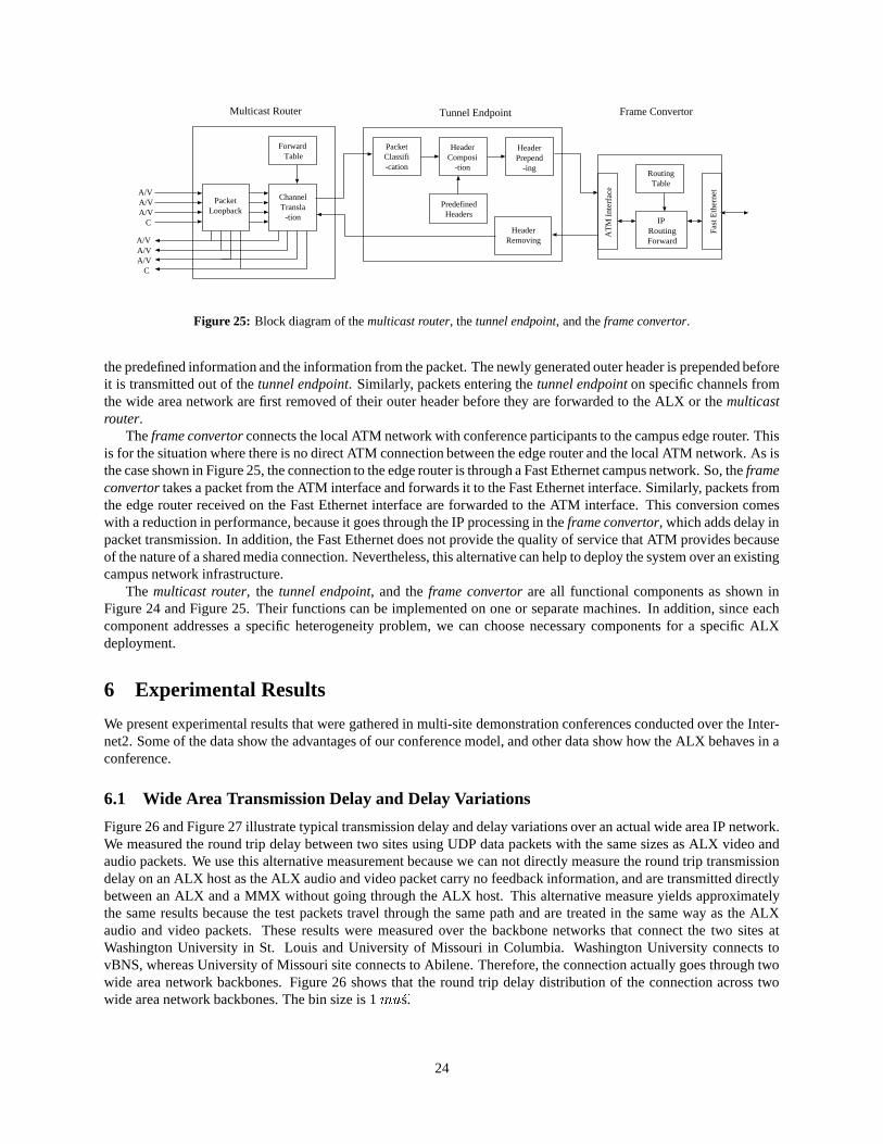
The frame convertor connects the local ATM network with conference participants to the campus edge router. Thisis for the situation where there is no direct ATM connection between the edge router and the local ATM network. As isthe case shown in Figure 25, the connection to the edge router is through a Fast Ethernet campus network. So, the frameconvertor takes a packet from the ATM interface and forwards it to the Fast Ethernet interface. Similarly, packets fromthe edge router received on the Fast Ethernet interface are forwarded to the ATM interface. This conversion comeswith a reduction in performance, because it goes through the IP processing in the frame convertor, which adds delay inpacket transmission. In addition, the Fast Ethernet does not provide the quality of service that ATM provides becauseof the nature of a shared media connection. Nevertheless, this alternative can help to deploy the system over an existingcampus network infrastructure.
The multicast router, the tunnel endpoint, and the frame convertor are all functional components as shown inFigure 24 and Figure 25. Their functions can be implemented on one or separate machines. In addition, since eachcomponent addresses a specific heterogeneity problem, we can choose necessary components for a specific ALXdeployment.
6 Experimental Results
We present experimental results that were gathered in multi-site demonstration conferences conducted over the Inter-net2. Some of the data show the advantages of our conference model, and other data show how the ALX behaves in aconference.
6.1 Wide Area Transmission Delay and Delay Variations
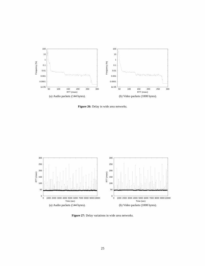
Figure 26 and Figure 27 illustrate typical transmission delay and delay variations over an actual wide area IP network.We measured the round trip delay between two sites using UDP data packets with the same sizes as ALX video andaudio packets. We use this alternative measurement because we can not directly measure the round trip transmissiondelay on an ALX host as the ALX audio and video packet carry no feedback information, and are transmitted directlybetween an ALX and a MMX without going through the ALX host. This alternative measure yields approximatelythe same results because the test packets travel through the same path and are treated in the same way as the ALXaudio and video packets. These results were measured over the backbone networks that connect the two sites atWashington University in St. Louis and University of Missouri in Columbia. Washington University connects tovBNS, whereas University of Missouri site connects to Abilene. Therefore, the connection actually goes through twowide area network backbones. Figure 26 shows that the round trip delay distribution of the connection across twowide area network backbones. The bin size is 1 � � �
s.
24
1e-05
0.0001
0.001
0.01
0.1
1
10
100
50 100 150 200 250 300
Fre
quen
cy (
%)
RTT (msec)
1e-05
0.0001
0.001
0.01
0.1
1
10
100
50 100 150 200 250 300
Fre
quen
cy (
%)
RTT (msec)
(a) Audio packets (144 bytes). (b) Video packets (1008 bytes).
Figure 26: Delay in wide area networks.
0
50
100
150
200
250
300
0 1000 2000 3000 4000 5000 6000 7000 8000 9000 10000
RT
T (
mse
c)
Time (sec)
0
50
100
150
200
250
300
0 1000 2000 3000 4000 5000 6000 7000 8000 9000 10000
RT
T (
mse
c)
Time (sec)
(a) Audio packets (144 bytes). (b) Video packets (1008 bytes).
Figure 27: Delay variations in wide area networks.
25
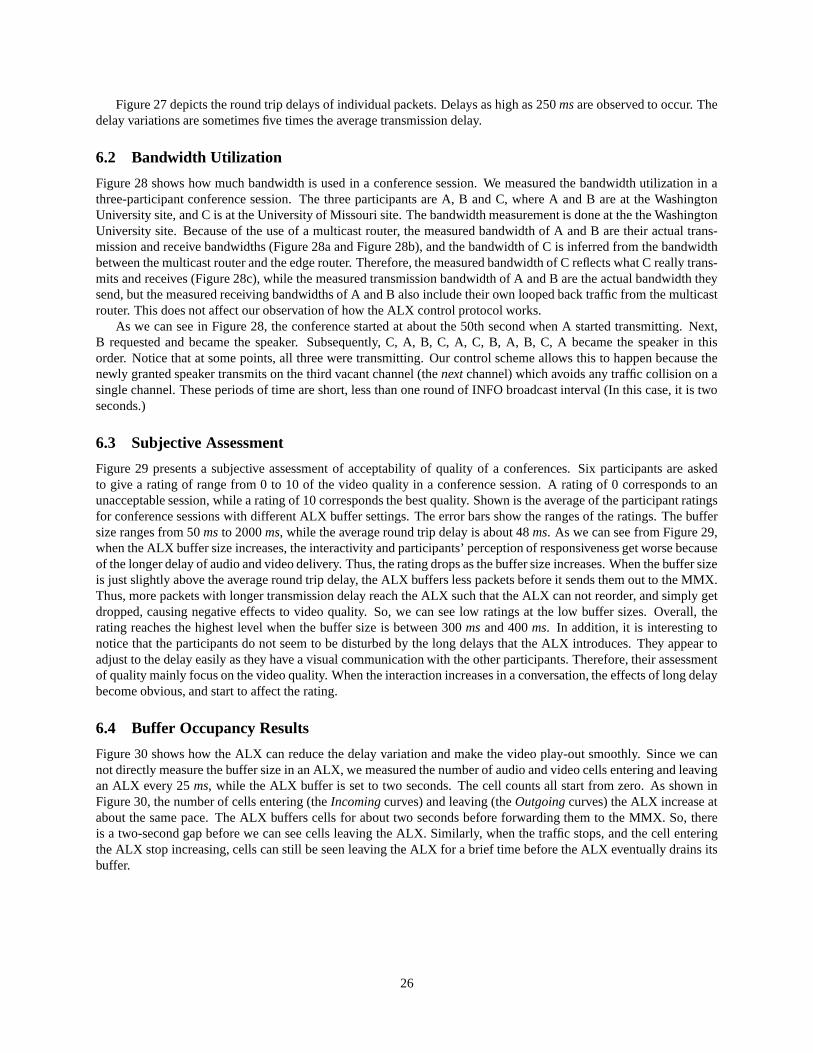
Figure 27 depicts the round trip delays of individual packets. Delays as high as 250 ms are observed to occur. Thedelay variations are sometimes five times the average transmission delay.
6.2 Bandwidth Utilization
Figure 28 shows how much bandwidth is used in a conference session. We measured the bandwidth utilization in athree-participant conference session. The three participants are A, B and C, where A and B are at the WashingtonUniversity site, and C is at the University of Missouri site. The bandwidth measurement is done at the the WashingtonUniversity site. Because of the use of a multicast router, the measured bandwidth of A and B are their actual trans-mission and receive bandwidths (Figure 28a and Figure 28b), and the bandwidth of C is inferred from the bandwidthbetween the multicast router and the edge router. Therefore, the measured bandwidth of C reflects what C really trans-mits and receives (Figure 28c), while the measured transmission bandwidth of A and B are the actual bandwidth theysend, but the measured receiving bandwidths of A and B also include their own looped back traffic from the multicastrouter. This does not affect our observation of how the ALX control protocol works.
As we can see in Figure 28, the conference started at about the 50th second when A started transmitting. Next,B requested and became the speaker. Subsequently, C, A, B, C, A, C, B, A, B, C, A became the speaker in thisorder. Notice that at some points, all three were transmitting. Our control scheme allows this to happen because thenewly granted speaker transmits on the third vacant channel (the next channel) which avoids any traffic collision on asingle channel. These periods of time are short, less than one round of INFO broadcast interval (In this case, it is twoseconds.)
6.3 Subjective Assessment
Figure 29 presents a subjective assessment of acceptability of quality of a conferences. Six participants are askedto give a rating of range from 0 to 10 of the video quality in a conference session. A rating of 0 corresponds to anunacceptable session, while a rating of 10 corresponds the best quality. Shown is the average of the participant ratingsfor conference sessions with different ALX buffer settings. The error bars show the ranges of the ratings. The buffersize ranges from 50 ms to 2000 ms, while the average round trip delay is about 48 ms. As we can see from Figure 29,when the ALX buffer size increases, the interactivity and participants’ perception of responsiveness get worse becauseof the longer delay of audio and video delivery. Thus, the rating drops as the buffer size increases. When the buffer sizeis just slightly above the average round trip delay, the ALX buffers less packets before it sends them out to the MMX.Thus, more packets with longer transmission delay reach the ALX such that the ALX can not reorder, and simply getdropped, causing negative effects to video quality. So, we can see low ratings at the low buffer sizes. Overall, therating reaches the highest level when the buffer size is between 300 ms and 400 ms. In addition, it is interesting tonotice that the participants do not seem to be disturbed by the long delays that the ALX introduces. They appear toadjust to the delay easily as they have a visual communication with the other participants. Therefore, their assessmentof quality mainly focus on the video quality. When the interaction increases in a conversation, the effects of long delaybecome obvious, and start to affect the rating.
6.4 Buffer Occupancy Results
Figure 30 shows how the ALX can reduce the delay variation and make the video play-out smoothly. Since we cannot directly measure the buffer size in an ALX, we measured the number of audio and video cells entering and leavingan ALX every 25 ms, while the ALX buffer is set to two seconds. The cell counts all start from zero. As shown inFigure 30, the number of cells entering (the Incoming curves) and leaving (the Outgoing curves) the ALX increase atabout the same pace. The ALX buffers cells for about two seconds before forwarding them to the MMX. So, thereis a two-second gap before we can see cells leaving the ALX. Similarly, when the traffic stops, and the cell enteringthe ALX stop increasing, cells can still be seen leaving the ALX for a brief time before the ALX eventually drains itsbuffer.
26
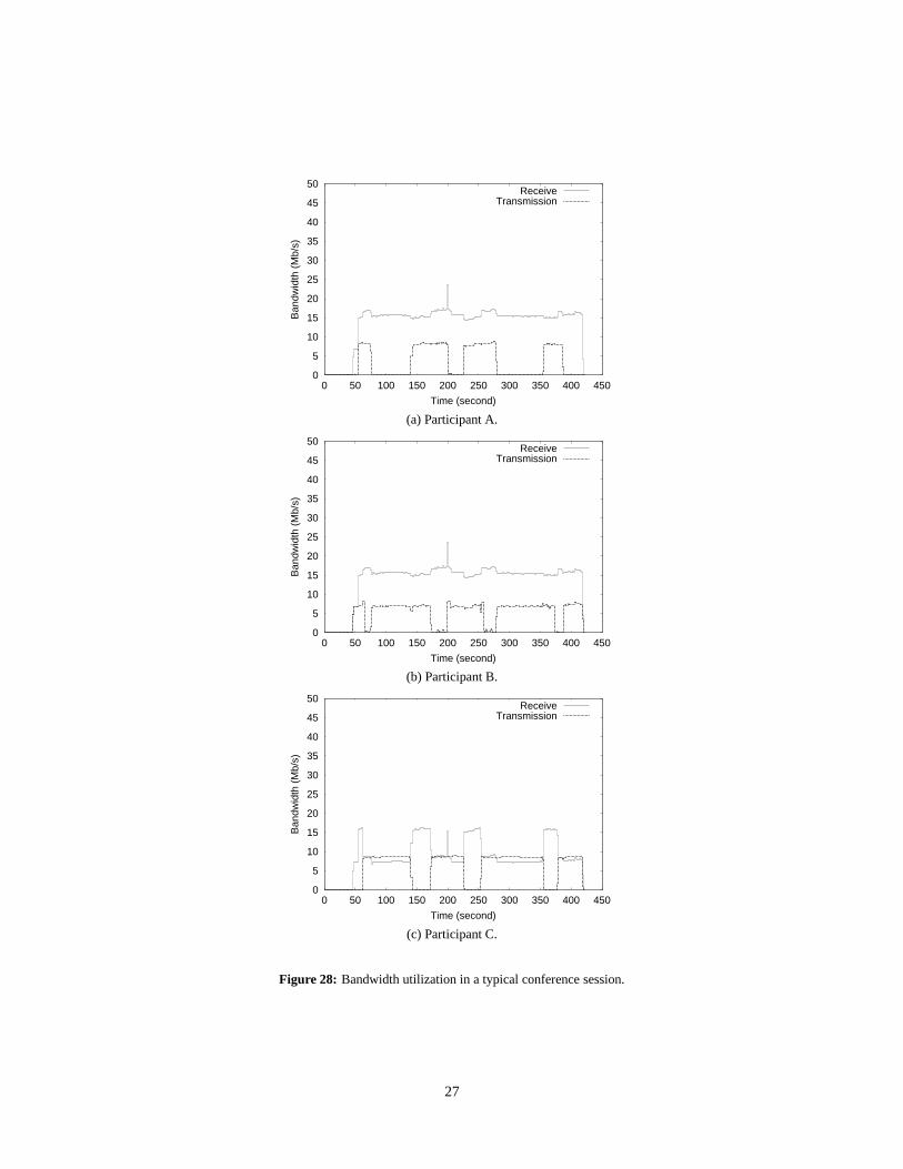
0
5
10
15
20
25
30
35
40
45
50
0 50 100 150 200 250 300 350 400 450
Ban
dwid
th (
Mb/
s)
Time (second)
ReceiveTransmission
(a) Participant A.
0
5
10
15
20
25
30
35
40
45
50
0 50 100 150 200 250 300 350 400 450
Ban
dwid
th (
Mb/
s)
Time (second)
ReceiveTransmission
(b) Participant B.
0
5
10
15
20
25
30
35
40
45
50
0 50 100 150 200 250 300 350 400 450
Ban
dwid
th (
Mb/
s)
Time (second)
ReceiveTransmission
(c) Participant C.
Figure 28: Bandwidth utilization in a typical conference session.
27
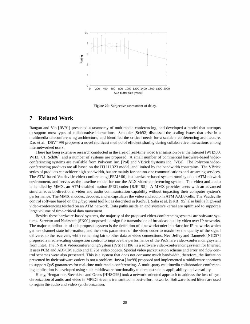
0
2
4
6
8
10
0 200 400 600 800 1000 1200 1400 1600 1800 2000
Rat
ing
ALX buffer size (msec)
Figure 29: Subjective assessment of delay.
7 Related Work
Rangan and Vin [RV91] presented a taxonomy of multimedia conferencing, and developed a model that attemptsto support most types of collaborative interactions. Schooler [Sch92] discussed the scaling issues that arise in amultimedia teleconferencing architecture, and identified the critical needs for a scalable conferencing architecture.Dao et al. [DSV � 99] proposed a novel multicast method of efficient sharing during collaborative interactions amonginternetworked users.
There has been extensive research conducted in the area of real-time video transmission over the Internet [WHZ00,WHZ � 01, Sch96], and a number of systems are proposed. A small number of commercial hardware-based video-conferencing systems are available from Polycom Inc. [Pol] and VBrick Systems Inc. [VBr]. The Polycom video-conferencing products are all based on the ITU H.323 model, and limited by the bandwidth constraints. The VBrickseries of products can achieve high bandwidth, but are mainly for one-on-one communications and streaming services.The ATM-based Vaudeville video-conferencing [PEM � 00] is a hardware-based system running on an ATM networkenvironment, and serves as the baseline model for our the ALX video-conferencing system. The video and audiois handled by MMX, an ATM-enabled motion-JPEG codec [RJE � 95]. A MMX provides users with an advancedsimultaneous bi-directional video and audio communication capability without impacting their computer system’sperformance. The MMX encodes, decodes, and encapsulates the video and audio in ATM AAL0 cells. The Vaudevillecontrol software based on the playground tool kit as described in [Gol95]. Saha et al. [SKB � 95] also built a high-endvideo-conferencing testbed on an ATM network. Data paths inside an end system’s kernel are optimized to support alarge volume of time-critical data movement.
Besides these hardware-based systems, the majority of the proposed video-conferencing systems are software sys-tems. Servetto and Nahrstedt [SN00] proposed a design for transmission of broadcast quality video over IP networks.The major contribution of this proposed system is the definition of a network/coder interface for IP networks whichgathers channel state information, and then sets parameters of the video coder to maximize the quality of the signaldelivered to the receivers, while remaining fair to other data or video connections. Nee, Jeffay and Danneels [NJD97]proposed a media-scaling congestion control to improve the performance of the ProShare video-conferencing systemfrom Intel. The INRIA Videoconferencing System (IVS) [TH96] is a software video-conferencing system for Internet.It uses PCM and ADPCM audio and H.261 video codecs. Special video packetization scheme and error and flow con-trol schemes were also presented. This is a system that does not consume much bandwidth, therefore, the limitationpresented by their software codecs is not a problem. Juvva [Juv99] proposed and implemented a middleware approachto support QoS guarantees for real-time multimedia conferencing. A multi-party multimedia collaboration conferenc-ing application is developed using such middleware functionality to demonstrate its applicability and versatility.
Hemy, Hengartner, Steenkiste and Gross [HHSG99] took a network-oriented approach to address the loss of syn-chronization of audio and video in MPEG streams transmitted in best-effort networks. Software-based filters are usedto regain the audio and video synchronization.
28
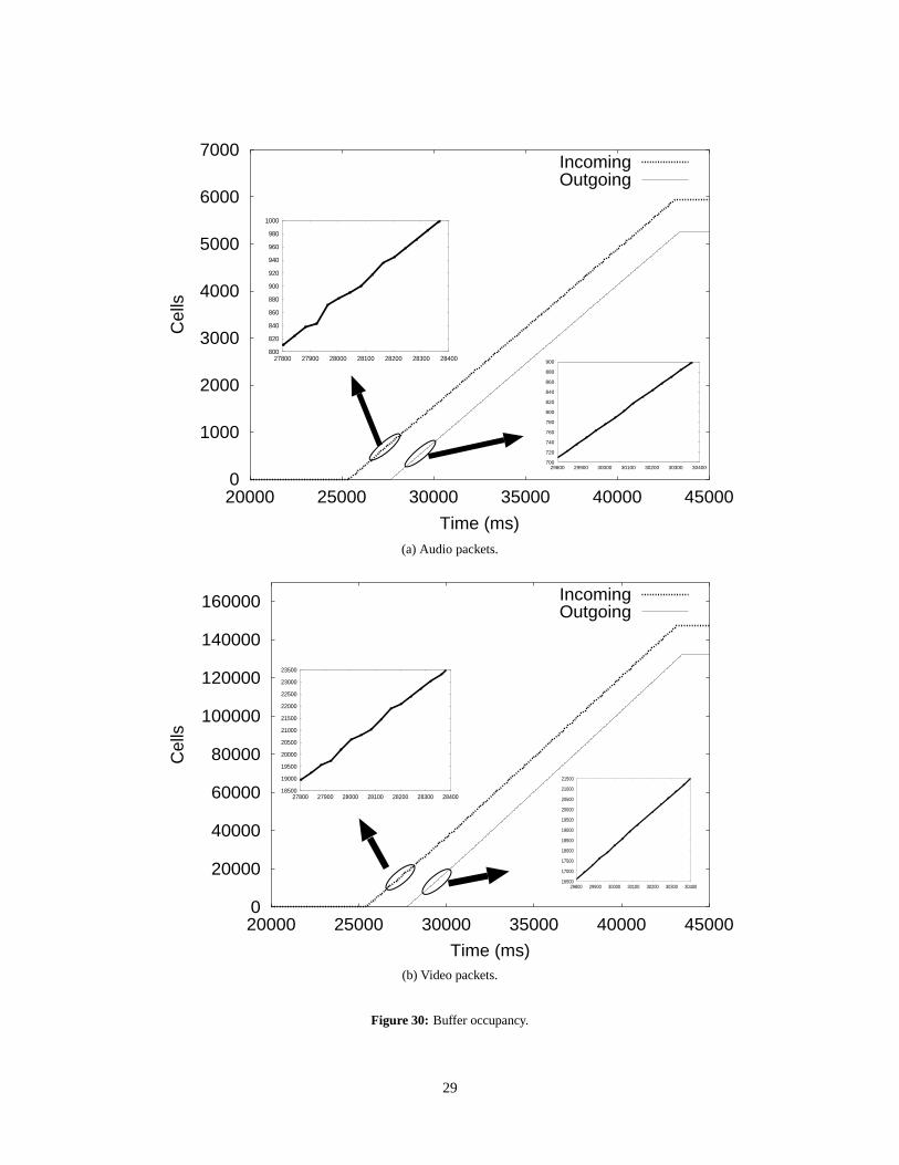
0
1000
2000
3000
4000
5000
6000
7000
20000 25000 30000 35000 40000 45000
Cel
ls
Time (ms)
IncomingOutgoing
800
820
840
860
880
900
920
940
960
980
1000
27800 27900 28000 28100 28200 28300 28400
700
720
740
760
780
800
820
840
860
880
900
29800 29900 30000 30100 30200 30300 30400
(a) Audio packets.
0
20000
40000
60000
80000
100000
120000
140000
160000
20000 25000 30000 35000 40000 45000
Cel
ls
Time (ms)
IncomingOutgoing
18500
19000
19500
20000
20500
21000
21500
22000
22500
23000
23500
27800 27900 28000 28100 28200 28300 28400
16500
17000
17500
18000
18500
19000
19500
20000
20500
21000
21500
29800 29900 30000 30100 30200 30300 30400
(b) Video packets.
Figure 30: Buffer occupancy.
29
8 Conclusions and Future Work
The distributed interactive collaboration is an essential activity in the scientific research community. Video-conferencingprovides an efficient means of such distributed scientific collaboration. In addition, the nature of scientific collabora-tion requires that such video-conferencing to be high quality. Meanwhile, the rapid growth of broadband wide area IPnetworks, such as the Internet2, makes it easy and inexpensive for institutions to access the required transport facilities.However, the existing video-conferencing systems for wide area IP networks based on the ITU H.323 reference modelcan not provide the high quality video and audio even though the broadband networks are available. On the other hand,the existing high quality video-conferencing systems are mainly developed for the local high bandwidth networks, andare not designed to handle issues present in wide area IP networks. All these considerations motivate our project toextend the high quality video-conferencing to broadband wide area IP networks for scientific collaboration.
To this end, we have designed and implemented a hardware device called the Adaptation Layer Translator (ALX)to bring the Vaudeville video-conference system for local ATM network to wide area IP networks, such as the Inter-net2. The ALX properly translates and encapsulates the local multimedia data traffic in ATM cells for transmissionover the wide area IP networks. Large buffers are used to smooth the delay variations, and audio and video syn-chronization is also handled carefully with embedded sequence numbers. A conference control protocol based on achannel rotation scheme coordinates the participants’ access to the shared media channels. ALX can be deployed invarious network environments with flexibility. We carried out multi-site video-conferences over the Internet2 with ourprototype systems, and proved such systems can be an efficient tool for remote interactive scientific collaboration.
In future work, we would like to extend our work to codecs other than MMX boxes. Inexpensive MPEG-2 codecswill be available in the near future so that the MMX can be replaced with such codecs and similar ideas to thoseimplemented in the ALX can be applied. In addition, besides video and audio, other shared materials, such as drawingson the white board, could also be useful to facilitate the remote scientific collaboration. Currently, the ALX has onlyone control channel that delivers user data to the host machine. This could be expanded such that user data of theshared materials could be processed by user applications.
Acknowledgments
This paper is based upon the work supported by the National Science Foundation (NSF) under the Grant Numbers9729618 and ASI-9619020. The authors would like to thank Bob Whitman, now of Celox Networks Inc., who madeenormous contributions to software design, network configuration and system tests. We would also like to express ourappreciation to Tom Chaney for his help with the hardware work. John DeHart and Steve Wiese assisted us with ATMnetwork and router configuration. We would like thank Dr. Gordon Springer and Arturo Guillen of the University ofMissouri-Columbia for making the experiment between our two sites possible.
References
[AM96] G. Ashish and D. McGee. ProShare Personal Conferencing Video System: an Evaluation of Technologyin Distance Learning, 1996.
[Arg] Argonne National Laboratories. Access Grid Project. URL http://www.accessgrid.org/.
[CGL � 01] G. Conklin, G. Greenbaum, K. Lillevold, A. Lippman, and Y. Reznik. Video coding for streaming mediadelivery on the Internet. IEEE Trans. on Circuits and Systems for Video Technology, 11(1), Feburary2001.
[CJ99] Michele Clark and Kevin Jeffay. Application-Level Measurements of Performance on the vBNS. InICMCS, Vol. 2, pages 362–366, 1999.
[DGLA95] Hans-Peter Dommel and J. J. Garcia-Luna-Aceves. Design issues for floor control protocols. In Multi-media and Networking, pages 305–16, 1995.
[DGLA97] Hans-Peter Dommel and J. J. Garcia-Luna-Aceves. Floor Control for Multimedia Conferencing andCollaboration. Multimedia Systems, 5(1):23–38, 1997.
30
[Dom98] Hans-Peter Dommel. Comparison of floor control protocols for collaborative multimedia environments,1998.
[DSV � 99] Son Dao, Eddie Shek, Asha Vellaikal, Richard R. Muntz, Lixia Zhang, Miodrag Potkonjak, and OuriWolfson. Semantic multicast: intelligently sharing collaborative sessions. ACM Computing Surveys,31(2es), 1999.
[FB99] M. Franceschetti and J. Bruck. A Possible Solution to the Impossible Membership Problem, 1999.
[Fer91] D. Ferrari. Design and application of a delay jitter control scheme for packet-switching internetworks.In Proceedings of the second International Conference on Network and Operating System Support forDigital Audio and Video, Heidelberg, Germany, 1991.
[Gol95] K. Goldman. Programmers’ Playground: Abstraction for User-Configurable Distributed Applications.IEEE Trans. on Software Eng., SE-21(9):735–746, 1995.
[Her95] Oliver Hermanns. Performance Evaluation of Connectionless Multicast Protocals for Cooperative Multi-media Applications. In Messung, Modellierung und Bewertung von, pages 372–384, 1995.
[HHSG99] M. Hemy, U. Hengartner, P. Steenkiste, and T. Gross. MPEG System Streams in Best-Effort Networks,1999.
[HS96] Oliver Hermanns and Marko Schuba. Performance investigations of the IP multicast architecture. Com-puter Networks and ISDN Systems, 28(4):429–439, 1996.
[Int90] International Telecommunication Union. Recommendation H.261, Video codec for audio visual servicesat� ��������� ���� , 1990.
[Int96a] International Telecommunication Union. ITU-T recommendation H.263: Video coding for low bit ratecommunication, 1996.
[Int96b] International Telecommunication Union. Visual telephone systems and equipment for local area networkswhich provide a non-guaranteed quality of service, 1996.
[Int97] Intel Corp. Intel Proshare Conferencing Video System 200. URL http://www.intel.com/proshare/ conferencing/, 1997.
[ISO92] ISO/MPEG Committee. Coding of moving pictures and associated audio - for storage at up to about 1.5mbits/s, 1992.
[ISO95] ISO/IEC. Generic Coding of Moving Pictures and Associated audio information, 1995.
[Juv99] Kanaka Juvva. A Real-Time Push-Pull Communications Model for Distributed Real-Time and Multime-dia Systems, 1999.
[KHW96] I. Kouvelas, V. Hardman, and A. Watson. Lip synchronisation for use over the Internet: analysis andimplementation. In GLOBECOM, 1996.
[Lau94] M. Laubach. Classical IP and ARP over ATM (RFC-1577), 1994.
[Mac92] W. Mackay. Spontaneous interaction in virtual multimedia space: EuroPARC’s RAVE system. In Imag-ina’92, 1992.
[MCI] MCI Worldcom Inc. very-high-performance Backbone Network Service (vBNS). URL http://www.vbns.net/.
[MCI00] MCI WorldCom vBNS Engineering Team. NSF very High Speed Backbone Network Service: Manage-ment and Operations Monthly Report. URL http://www.vbns.net/vbns/nettraff/2000/Jan.htm, 2000.
31
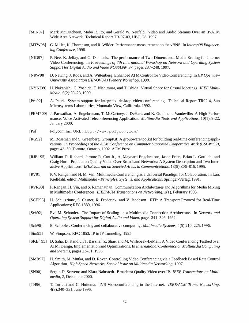
[MIN97] Mark McCutcheon, Mabo R. Ito, and Gerald W. Neufeld. Video and Audio Streams Over an IP/ATMWide Area Network. Technical Report TR-97-03, UBC, 28, 1997.
[MTW98] G. Miller, K. Thompson, and R. Wilder. Performance measurement on the vBNS. In Interop98 Engineer-ing Conference, 1998.
[NJD97] P. Nee, K. Jeffay, and G. Danneels. The performance of Two Dimensional Media Scaling for InternetVideo Conferencing. In Proceedings of 7th International Workshop on Network and Operating SystemSupport for Digital Audio and Video NOSSDAV’97, pages 237–248, 1997.
[NRW98] D. Newing, J. Roos, and A. Wittenberg. Enhanced ATM Control for Video Conferencing. In HP OpenviewUniversity Association (HP-OVUA) Plenary Workshop, 1998.
[NYNI99] H. Nakanishi, C. Yoshida, T. Nishimura, and T. Ishida. Virtual Space for Casual Meetings. IEEE Multi-Media, 6(2):20–28, 1999.
[Pea92] A. Pearl. System support for integrated desktop video conferencing. Technical Report TR92-4, SunMicrosystems Laboratories, Mountain View, California, 1992.
[PEM � 00] J. Parwatikar, A. Engebretson, T. McCartney, J. DeHart, and K. Goldman. Vaudeville: A High Perfor-mance, Voice Activated Teleconferencing Application. Multimedia Tools and Applications, 10(1):5–22,January 2000.
[Pol] Polycom Inc. URL http://www.polycom.com/.
[RG92] M. Roseman and S. Greenberg. GroupKit: A groupware toolkit for building real-time conferencing appli-cations. In Proceedings of the ACM Conference on Computer Supported Cooperative Work (CSCW’92),pages 43–50, Toronto, Ontario, 1992. ACM Press.
[RJE � 95] William D. Richard, Jerome R. Cox Jr., A. Maynard Engebretson, Jason Fritts, Brian L. Gottlieb, andCraig Horn. Production Quality Video Over Broadband Networks: A System Description and Two Inter-active Applications. IEEE Journal on Selected Areas in Communications, 13(5):806–815, 1995.
[RV91] P. V. Rangan and H. M. Vin. Multimedia Conferencing as a Universal Paradigm for Colaboration. In LarsKjelldahl, editor, Multimedia - Principles, Systems, and Applications. Springer-Verlag, 1991.
[RVR93] P. Rangan, H. Vin, and S. Ramanathan. Communication Architectures and Algorithms for Media Mixingin Multimedia Conferences. IEEE/ACM Transactions on Networking, 1(1), Feburary 1993.
[SCFJ96] H. Schulzrinne, S. Casner, R. Frederick, and V. Jacobson. RTP: A Transport Protocol for Real-TimeApplications; RFC 1889, 1996.
[Sch92] Eve M. Schooler. The Impact of Scaling on a Multimedia Connection Architecture. In Network andOperating System Support for Digital Audio and Video, pages 341–346, 1992.
[Sch96] E. Schooler. Conferencing and collaborative computing. Multimedia Systems, 4(5):210–225, 1996.
[Sim95] W. Simpson. RFC 1853: IP in IP Tunneling, 1995.
[SKB � 95] D. Saha, D. Kandlur, T. Barzilai, Z. Shae, and M. Willebeek-LeMair. A Video Conferencing Testbed overATM: Design, Implementation and Optimizations. In International Conference on Multimedia Computingand Systems, pages 23–31, 1995.
[SMR97] H. Smith, M. Mutka, and D. Rover. Controlling Video Conferencing via a Feedback Based Rate ControlAlgorithm. High Speed Networks, Special Issue on Multimedia Networking, 1997.
[SN00] Sergio D. Servetto and Klara Nahrstedt. Broadcast Quality Video over IP. IEEE Transactions on Multi-media, 2, December 2000.
[TH96] T. Turletti and C. Huitema. IVS Videoconferencing in the Internet. IEEE/ACM Trans. Networking,4(3):340–351, June 1996.
32
[TMW97] K. Thompson, G. Miller, and R. Wilder. Wide-Area Internet Traffic Patterns and Characteristics.IEEE/ACM Transactions on Networking, November 1997.
[TP94] Sebastian Toelg and Tomas Poggio. Towards an Example-Based Image Compression Architecture forVideo-Conferencing, 1994.
[Uni] University Corporation for Advanced Internet Development. Abilene. URL http://www.inter-net2.edu/abilene/.
[VBr] VBrick Systems Inc. URL http://www.vbrick.com/.
[Vid] Video Development Initiative(ViDe). Video Development Initiative Network (ViDeNet). URL http://www.vide.net/vc/videnet/.
[VRR91] H. Vin, P. Rangan, and S. Ramanathan. Hierarchical Conferencing Architectures for Inter-Group Mul-timedia Collaboration. In Conference on Organizational Computing Systems (COCS’91), pages 43–55,1991.
[VZF91] Dinesh C. Verma, Hui Zhang, and Domenico Ferrari. Delay Jitter Control for Real-Time Communica-tion in a Packet Switching Network. Technical Report TR-91-007, University of California at Berkeley,Berkeley, CA, 1991.
[Wal91] Gregory K. Wallace. The JPEG still picture compression standard. Communications of the ACM,34(4):30–44, 1991.
[WHZ00] Dapeng Wu, Yiwei T. Hou, and Ya-Qin Zhang. Transpoting Real-time Video over the Internet: Chal-lenges and Approaches. Proceedings of IEEE, 88, December 2000.
[WHZ � 01] Dapeng Wu, Yiwei Thomas Hou, Wenwu Zhu, Ya-Qin Zhang, and Jon M. Peha. Streaming Video over theInternet: : Approaches and Directions. IEEE Transactions on Circuit and Systems for Video Technoloy,11(1), February 2001.
[WS97] A. Watson and M. Sasse. Multimedia conferencing via multicast: determining the quality of servicerequired by the end user. In AVSPN, 1997.
[WS98] Anne Watson and Martina Angela Sasse. Measuring Perceived Quality of Speech and Video in Multime-dia Conferencing Applications. In ACM Multimedia, pages 55–60, 1998.
[YL94] Rajendra Yavatkar and K. Lakshman. Communication Support for Distributed Collaborative Applica-tions. Multimedia Systems, 2(2):74–88, 1994.
[YWW96] J. Yang, L. Wu, and A. Waibel. Focus of attention in video conferencing, 1996.
33