Embed Size (px)
Citation preview
-LC3PN COPY: RETURN TO AFLYL TECHNICAL LIBRARY
KiRfLAND AFB, M. M.
”.
ADAPTATION OF THE THEODORSEN THEORY TO THE REPRESENTATION OF A N AIRFOIL AS A COMBINATION OF A LIFTING L I N E A N D A THICKNESS DISTRIBUTION
Raymond L. Burger _ _ 8
Lungley Reseurch Center Hunpon, Va. 23 665
-... . .
N A T I O N A L AERONAUTICS A N D SPACE A D M I N I S T R A T I O N W A S H I N G T O N , D. C.’ . DECEMBER 1975 1 , . ‘ \ ‘ , 1 1 ,
https://ntrs.nasa.gov/search.jsp?R=19760005929 2018-05-03T06:57:17+00:00Z
TECH LIBRARY KAFB, NM
17. Key-Words (Suggested by Authoris) )
Airfoil Camber line Design
I Illill 1111 lllll1111111111 lllll lllll HI1 Ill
18. Distribution Statement
Unclassified - Unlimited
Subject Category 02
2. Government Accession No. 1 1. Report No. NASA TN D-8117
4. Title and Subtitle ADAPTATION O F THE THEODORSEN THEORY TO THE
19. Security Classif. (of this report) 20. Security Classif. (of this page)
Unclassified Unclassified
REPRESENTATION O F AN AIRFOIL AS A COMBINATION O F A LIFTING LINE AND A THICKNESS DISTRIBUTION
21. No. of Pages 22. Price'
18 1 $3.25
3. Recipient's Catalog No.
5. Report Date December 1975
6. Performing Organization Code
8. Performing Organization Report No. L-10476
505-06-31-02
i 7. Author(s)
Raymond L. Barger I 10. Work Unit No.
9. Performing Organization Name and Address
NASA Langley Research Center Hampton, Va. 23665
2. Sponsoring Agency Name and Address
National Aeronautics and Space Administration Washington, D.C. 20546
5. Supplementary Notes
11. Contract or Grant No.
13. Type of Report and Period Covered
Technical Note 14. Sponsoring Agency Code
I
6. Abstract
A representat ion o the Theodorsen airfoil theory as a combination of a lifting line The approximations of thin-airfoil theory are
The theory provides a direct and a thickness distribution is descr ibed. avoided, since the full potential theory is used throughout. method for resolving an airfoil into a lifting line and a thickness distribution as well as a means of synthesizing thickness and lift components into a resul tant airfoil and computing i t s aerodynamic character is t ics . Specific applications of the technique are discussed.
For sale by the National Technical Information Service, Springfield, Virginia 221 61
I
ADAPTATION OF THE THEODORSEN THEORY TO THE REPRESENTATION
OF AN AIRFOIL AS A COMBINATION OF A LIFTING LINE
AND A THICKNESS DISTRIBUTION
Raymond L. Barger Langley Research Center
SUMMARY
A representation of the Theodorsen airfoil theory as a combination of a lifting line The approximations of thin-airfoil theory are
The theory provides a direct and a thickness distribution is described. avoided, since the ful l potential theory is used throughout. method for resolving an airfoil into a lifting line a.nd a thickness distribution as well as a means of synthesizing thickness and lift coinponents into a resultant airfoil and computing i t s aerodynamic characterist ics. Specific applications of the technique a r e discussed.
INTRODUCTION
The thin-airfoil technique of representing an airfoil as a combination of a thickness distribution and a camber line is widely used because of the availability of a body of appro- priate data (ref. 1) and because the method facilitates design, inasmuch as i t enables the designer to t reat the lifting and thickness components separately. On the other hand, the thin-airfoil theory itself is vulnerable to cri t icism on several grounds regarding both the consistency of the theory and the accuracy of the procedures. Fo r example, the procedure of superimposing a thickness distribution normal to the camber line involves a nonuniform stretching of the basic thickness profile. Furthermore, the simple addition of velocities due to thickness, camber , and angle of attack i s not always reliable. ous difficulty is the failure of thin-airfoil theory to provide reasonable velocity values in the nose region. To improve the accuracy of the calculations in this region requires in- volved procedures. Finally, although the theory gives explicit equations for computing airfoil coordinates from thickness and camber distributions, i t provides no analytic means for accomplishing the inverse task - that of resolving a given airfoil into its thickness and camber components.
An even more seri-
The present report describes a method for representing the Theodorsen airfoil theory as a combination of a lifting line and a thickness distribution. approximations of thin-airfoil theory are avoided, since the full potential theory is used throughout. Within the framework of the full potential theory, the new method not only
In this approach the
provides formulas for synthesizing an airfoil from a lifting line and a thickness distribu- tion, but it a lso provides analytic means for resolving a given airfoil into i ts thickness and lifting-line components. design procedures. and convenient in application.
This latter capability is especially useful in certain airfoil Both tke synthesis and the analysis procedures a r e simple in concept
SYMBOLS
An 9 %
a
CP
C
R
r
V
V
X,Y
(Y
OI
(YO
E
E N
‘te
2
Fourier coefficients
= Re - G O
pres su re coefficient
airfoil chord length
radius of c i rc le into which an airfoil is mapped by the Theodorsen transformation
radial coordinate in near -circle plane
undisturbed free -stream velocity
local velocity
P irfoil coordinates
angle of attack
‘N + ‘te ideal angle of attack, - 2
angle of attack a t zero lift
function relating angular coordinates of near -circle and exact -circle airfoil transformations
value of E at airfoil nose, € ( e ) a t e = 0
value of E a t airfoil trailing edge, € ( e ) a t 8 = 7~
G angular coordinate in near -circle plane
6 angular coordinate in exact -circle plane
(6* dummy variable of integration
+ function relating radial coordinates of near-circle and exact-circle airfoil t rans f o r ni a t i o ns
average value of + +O
Subscripts:
a antisymmetric
S s ym metric
Pr imes indicate derivatives with respect to 0.
BASIC CONCEPTS
Potential Theory
Before reviewing some thin-airfoil techniques, i t is convenient f i r s t to state the basic formulas of the Theodorsen transformation theory for airfoil analysis. These for - mulas are useful in understanding the following discussion of thin-airfoil techniques, and they a r e required in the subsequent analysis section.
The Theodorsen airfoil theory (ref. 2) involves the Joukowski transformation of the In the transformed plane, this near c i rc le is airfoil into a shape approximating a circle .
described by polar coordinates (r,O). an exact c i rc le having coordinates (R,$). The function + and the constant q0 are defined by r = aeq and R = ae'o. of +, that is,
The approximate circle is then transformed into
is the average value Theodorsen shows that
3
and that the functions Q - Qo and E = @ - 8 are related by the conjugate equations
1 2a @* - @ IC/ - +bo = - 1 E cot - d@* 2 237 0
The function +b is directly related to the airfoil coordinates in the physical plane by
x = 2a cosh Q cos 6'
y = 2a sinh IC/ sin 8
(3)
(4)
In practice, +b is obtained directly as a function of 8 from equations (4), and then the function € ( e ) is obtained by taking the conjugate of Q. To be more precise, E ( @ )
should be obtained by iteration by means of the relation be calculated from precision gained by this s tep is slight (ref. 3 ) , and so it is often omitted. distribution on the airfoil is computed from the equation
@ = E + 8, and then E(0) should E ( 8 ) = E / $ ( @ ) ! . However, for practical airfoil shapes the additional
The velocity
Comments on Thin-Airfoil Methods
The thin-airfoil theory, which affords a simple approximate procedure of synthesiz- ing and analyzing an airfoil by combining lifting-line and thickness elements, does not pro- vide a means for separating a given airfoil into i t s camber line and thickness distribution. Furthermore , the thin-airfoil calculation of the velocity, by a distribution of sources and sinks along the axis, gives a poor approximation, especially in the nose region. Attempts to improve the accuracy of the basic thin-airfoil theory have led to complicated proce- dures. (See sec. 4.5 of ref. 1, and ref. 4.)
Another difficulty is that the thin-airfoil method of obtaining a profile by superim- posing a thickness distribution (fig. l(a)) normal to a camber line, as illustrated in fig- ure l(b) , is an approximate procedure. The a r c length of the camber line is longer than the chord of the original thickness profile, and therefore the thickness form undergoes a distortion, the stretching being greater for the upper surface than for the lower surface. The simpler thin-airfoil procedure, which attributes the lift to a mean line with the thick-
4
ness distribution superimposed on i t in 2. vertical direction (fig. l(c)), is an even poorer approximation. With this procedure, not only is the thickness distribution distorted, but the effective camber line is changed also.
A theory that avoids some of the difficulties of the thin-airfoil methods is described in the following section.
ANALYSIS AND APPLICATIONS
Airfoil Synthesis From Thickness and Lift Components
This section describes the theory and procedure for synthesizing an airfoil by com- bining an arbi t rary thickness distribution with an arbi t rary lifting line within the context of the full potential theory. The aerodynamic relationships between the resulting a.irfoi1 and i ts thickness and lifting-line components a r e also discussed.
In equations (a) and (b) of reference 2 , it is shown that (if 0 is substituted for @, as previously discussed) E and q can be expressed by
m
- E = - - ( B ~ 1 cos ne - A, sin nej L Rn n= 0
m
I$ - qo = -(An 1 cos ne + Bn sin ne) LJ Rn n= 0
From i t s definition, E must be a continuous function of 6 , and therefore,
E(0) = E(277) = E N
It follows from equation (sa) that
(7)
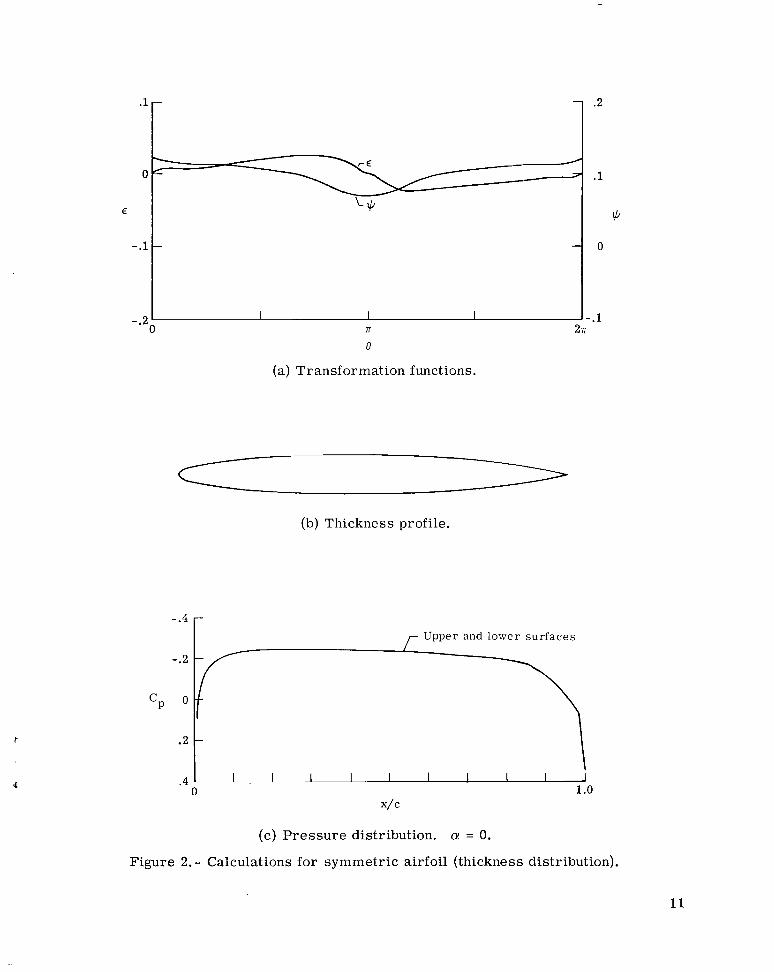
Now consider first the case for which E is antisymmetric about a (fig. 2(a)); that is, €(a-6) = -€(a+@. Then Bn = 0 fo r all n, and therefore the conjugate function + - q0 is symmetric about a (fig. 2(a)). Since +o is constant, +(a-e) = +(n+f?). Consequently cosh +(n-e) = cosh +(n+e) and sinh +(n-e) = sinh +(a+e). Thus in equa- tions (4) for the airfoil coordinates, x(n+8) = x(n-e); that is, x is symmetric with
5
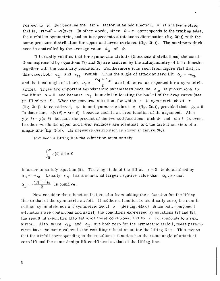
respect to n. But because the s in 6 factor is an odd function, y is antisymmetric; that is, y(n-I-6) = -y(n-6). In other words, since 6 = n corresponds to the trailing edge, the airfoil is symmetr ic , and so it represents a thickness distribution (fig. 2(b)) with the same pressure distribution for upper and lower surfaces (fig. 2(c)). The maximum thick- ness is controlled by the average value *o of *.
tions expressed by equations (7) and (8) a r e assured by the antisymmetry of the €-function together with the continuity conditions. this case, both e N and ete vanish. Thus the angle of attack a t zero lift a. = -ete
I t is easily verified that for symmetric airfoils (thickness distributions) the condi-
Furthermore i t is seen from figure 2(a) that, in
- .
E N -t- Ete a r e both zero, as expected for a symmetric and the ideal angle of attack crI = - 2
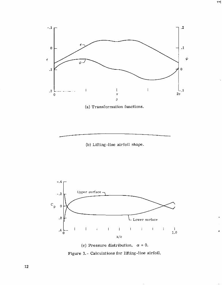
airfoil. These a r e important aerodynamic parameters because E te is proportional to the lift at CY = 0 and because aI is useful in locating the bucket of the drag curve (see pt. I11 of ref . 5). When the converse situation, for which E is symmetric about n (fig. 3(a)), is considered, Q is antisymmetric about 71 (fig. 3(a)), provided that Qo = 0. In that case, x(n+8) = x(n-e) because cosh i s an even function of i t s argument. y(ni-e) = y(n-e) because the product of the two odd functions sinh Q and sin 6 is even. In other words the upper and lower surfaces a r e identical, and the airfoil consists of a single line (fig. 3(b)).
Also
Its pressure distribution is shown in figure 3(c).
For such a lifting line the E-function must satisfy
in order to satisfy equation (8). cyo = -Ete. Usually f N has a somewhat larger negative value than c y o , so that
The magnitude of the lift at cy = 0 i s determined by
+ is positive. 2
CYI = -
Now consider the €-function that results from adding the e-function for the lifting line to that of the symmetric airfoil. neither symmetric nor antisymmetric about n. (See fig. 4(a) .) Since both component €-functions a r e continuous and satisfy the conditions expressed by equations (7) and (8), the resultant E-function also satisfies these conditions, and s o corresponds to a real airfoil. Also, since Ete and a r e both zero for the symmetric airfoil, these parain- e t e r s have the same values in the resulting e-function as for the lifting line. that the airfoil corresponding to the resultant E-function has the same angle of attack at zero lift and the same design lift coefficient as that of the lifting line.
If neither €-function is identically zero, the sum is
E
This means
6
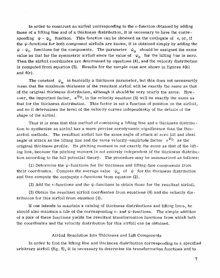
In order to construct an airfoil corresponding to the €-function obtained by adding those of a lifting line and of a thickness distribution, it is necessary to have the cor re- sponding + - qb0 function. This function can be obtained as the conjugate of E, o r , if the +-functions for both component airfoils are known, i t is obtained simply by adding the + - +o functions for the components. The parameter +o should be assigned the same value as that for the symmetric airfoil since the value of for the lifting line is zero. Then the airfoil coordinates are determined by equations (4), and the velocity distribution is computed from equation (5). Results for the sample case a r e shown in figures 4(b) and 4(c).
q0
The constant Q0 is basically a thickness parameter , but this does not necessarily mean that the maximum thickness of the resultant airfoil will be exactly the same as that of the original thickness distribution, although it should be very nearly the same. How- ever , the important factor, e%, in the velocity equation (5) will be exactly the same as that for the thickness distribution. This factor is not a function of position on the airfoil, and so i t determines the level of the velocity curves independently of the details of the shape of the airfoil.
Thus it is seen that this method of combining a lifting line and a thickness distribu- tion to synthesize an airfoil has a more precise aerodynamic significance than the thin- airfoil methods. angle of attack as the lifting line and the same velocity-amplitude factor e@O as the original thickness profile. I ts pitching moment is not exactly the same as that of the lift- ing line, because the pitching moment is not entirely independent of the thickness distribu- tion according to the fu l l potential theory. The procedure may be summarized as follows:
The resultant airfoil has the same angle of attack at zero lift and ideal
(1) Determine the @-functions for the thickness and lifting-line components from their coordinates. Compute the average value @o of @ for the thickness distribution and then compute the conjugate E-functions from equation (2).
(2) Add the E-functions and the @-functions to obtain those for the resultant airfoil.
(3) Obtain the resultant airfoil coordinates from equations (4) and the velocity dis- tribution for this airfoil from equation (5).
If one intends to maintain a catalog of thickness distributions and lifting lines, he should also maintain a file of the corresponding E- and @-functions. The simple addition of a pair of these functions yields the resultant transformation functions from which both the coordinates and the velocity distribution for this airfoil can be obtained.
Airfoil Resolution Into Thickness and Lift Components
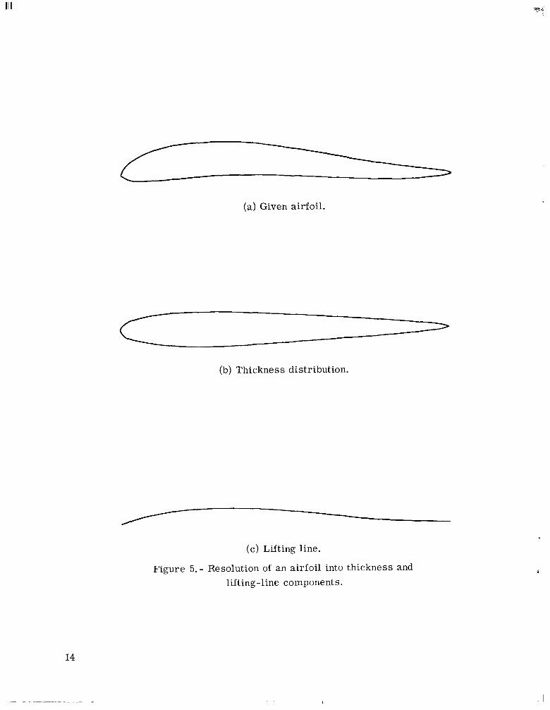
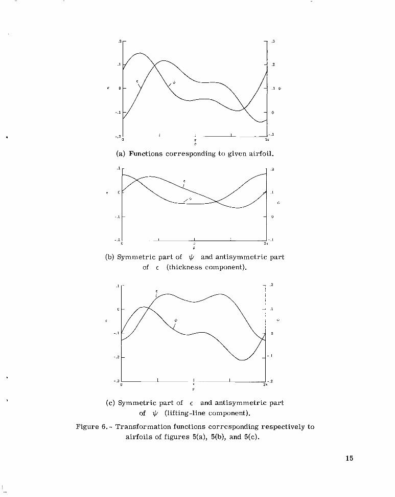
In order to find the lifting line and thickness distribution corresponding to a specified arbi t rary airfoil (fig. 5), it is necessary to determine its transformation functions and to
7
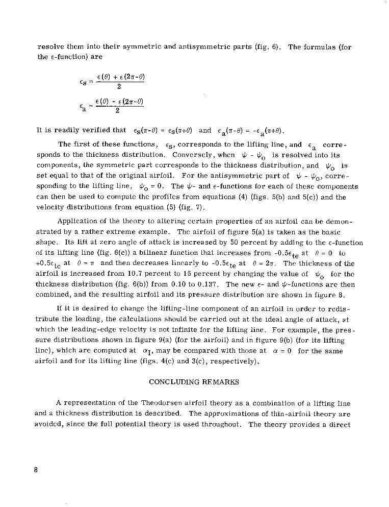
resolve them into their symmetric and antisymmetric par ts (fig. 6). the E-function) are
The formulas (for
It is readily verified that es(.rr-O) = Es(.rr+O) and E ( n - 0 ) = - E (.rr+0). a a The first of these functions, eS, corresponds to the lifting line, and ea co r re -
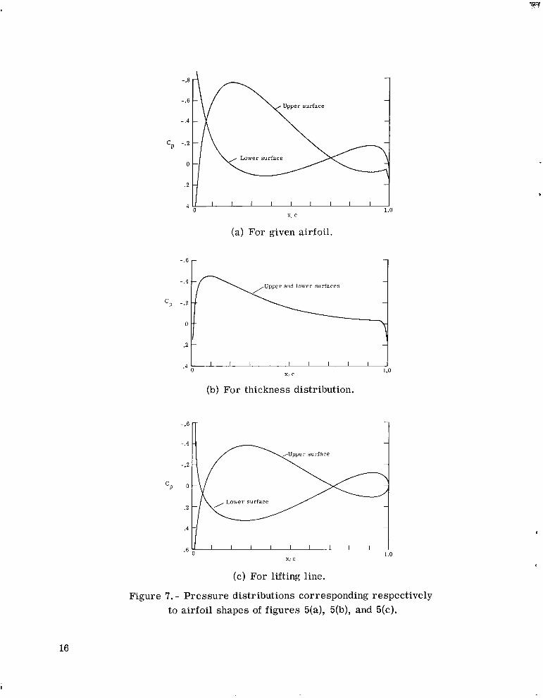
sponds to the thickness distribution. Conversely, when + - is resolved into its components, the symmetric par t corresponds to the thickness distribution, and IC/, is set equal to that of the original airfoil. For the antisymmetric part of + - t,b0, co r re - sponding to the lifting line, Go = 0. The I$- and €-functions for each of these components can then be used to compute the profiles f rom equations (4) (figs. 5(b) and 5(c)) and the velocity distributions from equation (5) (fig. 7).
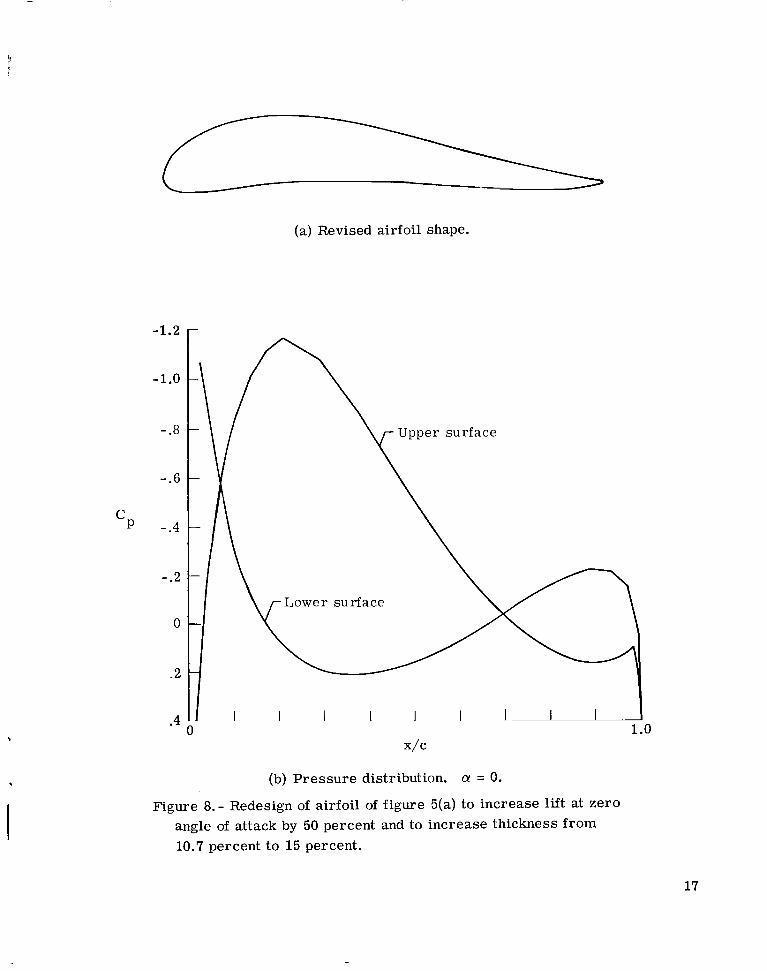
Application of the theory to altering certain properties of an airfoil can be demon- s t ra ted by a rather extreme exarnple. shape. Its lift at zero angle of attack is increased by 50 percent by adding to the E-function of its lifting line (fig. G(c)) a bilinear function that increases from - 0 . 5 ~ ~ ~ at +0.5ete a t 0 = .rr and then decreases linearly to - 0 . 5 ~ ~ ~ at 0 = 271. The thickness of the airfoil is increased from 10.7 percent to 15 percent by changing the value of q0 for the thickness distribution (fig. 6(b)) from 0.10 to 0.137. The new E- a.nd +-functions a r e then combined, and the resulting airfoil and i t s pressure distribution a r e shown in figure 8.
The airfoil of figure 5(a) is taken as the basic
0 = 0 to
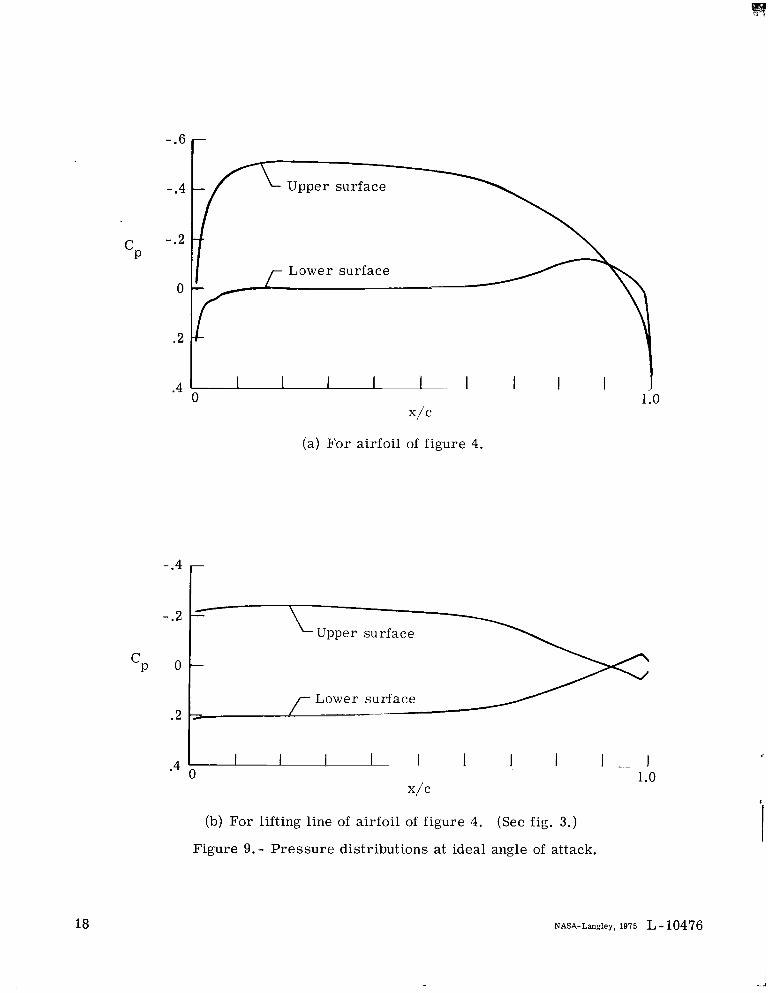
If i t is desired to change the lifting-line component of an airfoil in order to redis- tribute the loading, the calculations should be carr ied out a t the ideal angle of attack, a t which the leading-edge velocity is not infinite for the lifting line. For example, the pres - sure distributions shown in figure 9(a) (for the airfoil) and in figure 9(b) (for i ts lifting line), which are computed at q, may be compared with those a t CY = 0 for the same airfoil and for i t s lifting line (figs. 4(c) and 3(c), respectively).
CONCLUDING REMARKS
A representation of the Theodorsen airfoil theory as a combination of a lifting line and a thickness distribution is described. The approximations of thin-airfoil theory are avoided, since the full potential theory is used throughout. The theory provides a direct
8
method for resolving an airfoil into a lifting line and a thickness distribution as well as a means of synthesizing thickness and lift components into a resultant airfoil and computing i t s aerodynamic characterist ics. Some specific applications of the technique are discussed.
Langley Research Center National Aeronautics and Space Administration Hampton, Va. 23665 December 2, 1975
REFERENCES
1. Abbott, I r a H.; and Von Doenhoff, Albert E.: Theory of Wing Sections. Dover Publ., Inc., c. 1959.
2. Theodorsen, Theodore: Theory of Wing Sections of Arbitrary Shape. NACA Rep. 411, 19 3 1.
3. Theodorsen, T.; and Garrick, I. E.: General Potential Theory of Arbitrary Wing Sections. NACA Rep. 452, 1933.
4. Allen, H. Julian: General Theory of Airfoil Sections Having Arbitrary Shape or Pressure Distribution. NACA Rep. 833, 1945.
5. Theodorsen, Theodore: On the Theory of Wing Sections With Particular Reference to the Lift Distribution. NACA Rep. 383, 1931.
9
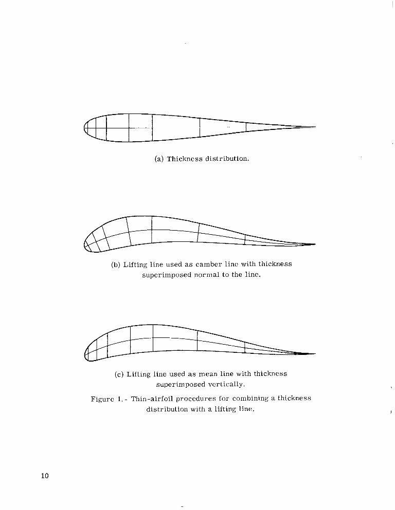
(a) Thickness distribution.
(b) Lifting line used as camber line with thickness superimposed normal to the line.
/--
(c) Lifting line used as mean line with thickness super imposed vertically.
Figure 1. - Thin-airfoil procedures for combining a thickness distribution with a lifting line.
10
.1
a
E
-.l
-.2 0 IT
e
(a) Transformation functions.
(b) Thickness profile.
.2
.1
0
..1
I 1 I I I I I I _I 0 1 .o
(c) Pressure distribution. a! = 0.
Figure 2. - Calculations for symmetric airfoil (thickness distribution).
11
Upper surface
(a) Transformation functions.
- (b) Lifting-line airfoil shape.
.4 L I I I 1 . 1 I I 1 I J 0 1.0
x/c
(c) Pressure distribution. a! = 0.
Figure 3. - Calculations for lifting-line airfoil.
12
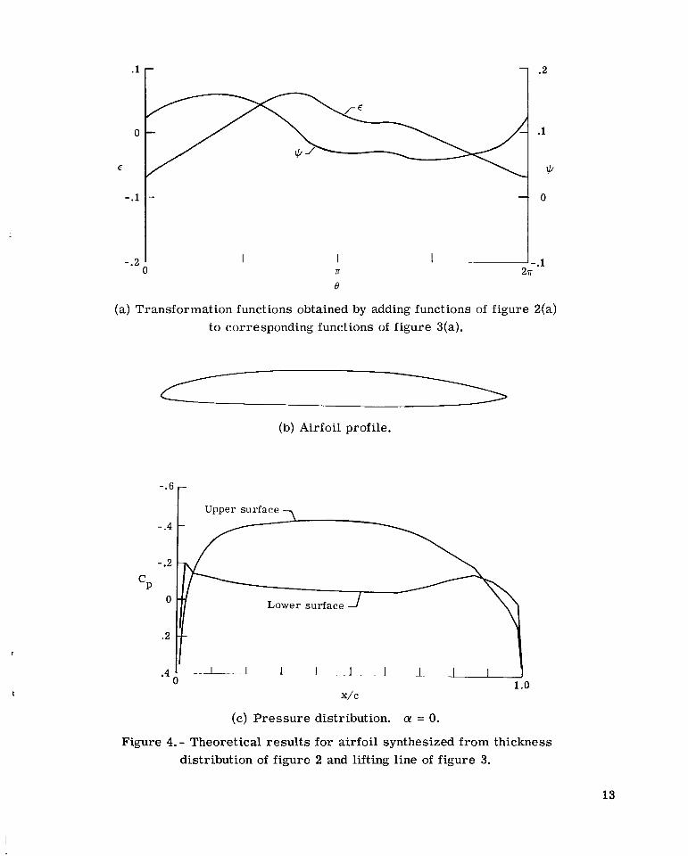
(a) Transformation functions obtained by adding functions of figure 2(a) to corresponding functions of figure 3(a).
(b) Airfoil profile.
- .1
-.2
( c ) Pressu re distribution. a! = 0.
Figure 4. - Theoretical resu l t s for airfoil synthesized from thickness distribution of figure 2 and lifting line of figure 3.
13
II I
14
- . .. . . ..
(a) Given airfoil.
(b) Thickness distribution.
(c) Lifting line.
Figure 5. - Resolution of an airfoil into thickness and lifting-line components.
I
(a) Functions corresponding to given airfoil.
I I I J -.1 77 2 n 0
(b) Symmetric part of +b and antisymmetric part of E (thickness component).
.1
0
E
- . l
-.2
- . 3
E
n 0
.2
1
ii
0
1
2
(c) Symmetric part of E and antisymmetric part of +b (lifting-line component).
Figure 6. - Transformation functions corresponding respectively to airfoils of figures 5(a), 5(b), and 5(c).
15
-.8
-.6
-.4
cp -.2
0
.2
.4
-.6
-.4
c p - .2
0
.2
l I 1 I I l I l I l l 1 .o
x, c
(a) For given airfoil.
-.6
- .4
-.2
0
.2
.4
.6
(b) For thickness distribution.
1
1 I 1.0
x, c
(c) For lifting line.
Figure 7. - Pressure distributions corresponding respectively to airfoil shapes of figures 5(a), 5(b), and 5(c).
16
(a) Revised airfoil shape.
,
-1.2
-1.0
- .8
- . 6
-.4
- .2
0
.2
\ r L o w e r surface \ ,
1 1 1 1 1 .o
I I 0
.4
x/c
(b) P res su re distribution. a = 0.
Figure 8.- Redesign of airfoil of f igure 5(a) to increase lift at zero angle of attack by 50 percent and to increase thickness from 10.7 percent to 15 percent.
17
-.6
- .4
-.2 cP
0
.2
.4
Upper surface
Lower surface
I 1 I I 1 1 1 1 1 1 1.0
x/c
(a) For airfoil of figure 4.
Upper surface
Lower surface
(b) For lifting line of airfoil of figure 4. (See fig. 3 . )
Figure 9.- Pressure distributions at ideal angle of attack.
18 NASA-Langley, 1975 L - 10476
NATIONAL AERONAUTICS AND SPACE ADMINISTRATION
WASHINGTON. D.C. 20546 POSTAGE A N D FEES P A I D
NATIONAL AERONAUTICS AND OFFICIAL BUSINESS SPACE A D M I N I S T R A T I O N
451 USMAIL
PENALTY FOR PRIVATE USE $300 SPECIAL FOURTH-CLASS RATE
BOOK v .
d t , ?
1 ,J
7‘39 001 C’l IJ A 751212 SO139031)S ‘
DEFT OF THE R I B FORCE AF WEAPONS L A B O R A T O R Y ATTN: TECHNICAL L I B R A R Y { S U L ) K I R T L A N D A P E NM 87117
: If Undeliverable (Section 158 Postal Rfnnunl) Do Not Return
, < -” ._ - _ - -
*. “The aeronautical and space activities of the United States shall be
conducted so as to contribute . . . t o the expansion of human howl- edge of phenomena in the atmosphere and space. T h e Administration shall provide for the widest practicable and appropriate dissemination of information concerning its activities and the results thereof.”
’.
-NATIONAL AERONAUTICS AND SPACE ACT OF 1958
NASA SCIENTIFIC AND TECHNICAL PUBLICATIONS TECHNICAL REPORTS: Scientific and technical information considered important, complete, and a lasting contribution to existing knowledge.
TECHNICAL NOTES: Information less broad in scope but nevertheless of importance as a contribution to existing knowledge.
TECHNICAL TRANSLATIONS: Information published in a foreign language considered to merit NASA distribution in English.
SPECIAL PUBLICATIONS: Information derived from or of value to NASA activities. Publications include final reports of major - - projects, monographs, data compilations, handbooks, sourcebooks, and special bibliographies.
TECHNICAL MEMORANDUMS: Information receiving limited distribution because of preliminary data, security classifica- tion, or other reasons. Also includes conference proceedings with either limited r unlimited distribution.
TECHNOLOGY UTILIZATION PUBLICATIONS: Information on technology used by NASA that may be of particular
% -
CONTRACTOR REPORTS: Scientific and technical information generated under a NASA contract or grant and considered an important contribution to existing knowledge.
interest in commercial and other- non-aerospace applications. Publications include Tech Briefs, Technology Utilization Reports and Technology Surveys.
Details on the availability of these publications may be obtained from:
SCIENTIFIC AND TECHNICAL INFORMATION OFFICE
N A T I O N A L A E R O N A U T I C S A N D SPACE A D M I N I S T R A T I O N Washington, D.C. 20546