Embed Size (px)
Citation preview
Blue Bell, PA 19422(215) 643-0192
Blue Bell, PA 19422(215) 643-1900
® ®
® ®
ADAPTERS and CONNECTORS MODULAR VALVES and FITTINGS
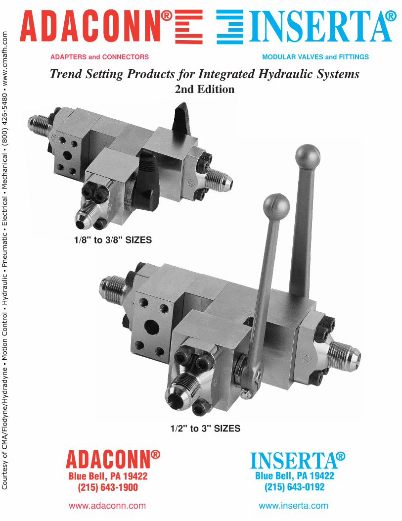
Trend Setting Products for Integrated Hydraulic Systems2nd Edition
1/8" to 3/8" SIZES
1/2" to 3" SIZES
www.adaconn.com www.inserta.com
Court
esy
of CM
A/F
lodyn
e/H
ydra
dyn
e ▪
Motion C
ontr
ol ▪
Hyd
raulic
▪ P
neu
mat
ic ▪
Ele
ctrica
l ▪
Mec
han
ical
▪ (
800)
426-5
480 ▪
ww
w.c
maf
h.c
om
INDEX PAGE
USE THE ADACONN® + INSERTA® ALTERNATIVES 2 – 3
INSERTA® IBF Ball Valves, Standard and High Pressure Flange Type – 2 Port 4 – 5
INSERTA® IBF3D Ball Valves, Standard and High Pressure Flange Type – 3 Port Diverter 6 – 7
INSERTA® ICS Check Valves, Slip-In Type 8 – 9
INSERTA® ICF Check Valve Bodies, Flange Type 10 – 11
INSERTA® ICFS Check Valve Bodies with Support Member, Flange Type 12 – 13
INSERTA® ICC Check Valve Carriers, Thread–In Type 14 – 15
INSERTA® ICT Check Valves, Thread-In Type 16 – 17
INSERTA® ICFT Check Valves, Flange Type 18 – 19
VIEWING INSERTA® IEL, ITR, ITB & ICX Modular Connectors, 4-Bolt, Flange Type 20 – 21
TREND SETTING ADACONN® + INSERTA® Flange Adapters and Flange Ports, UNIFIED CODE U61 4 and 2-Bolt, Flange Type 22
INSERTA® ICX, IEL, ITB, ITR, IPC & IPS Modular Connectors, UNIFIED CODE U61 4-Bolt, Flange Type 23 – 25
INSERTA® IBP, IGC, IOP and ISP Specialty Plates, Flange Type 26 – 27
INSERTA® IFRA 90° Rotational Retaining Adapters, 4-Bolt Flange Type 28 – 29
INSERTA® IFRC 90° Rotational Connectors, 4-Bolt Flange Type 30 – 31
ADAFLANGE™ Adapters, UNIFIED CODE U61 4-Bolt, Flange Type 32 – 33
FLEXIBILITY OF ADACONN® + INSERTA® Flange Adapters and Flange Ports, UNIFIED CODE U61 4 & 2-Bolt, Flange Type 34
INSERTA® ICX, IEL, ITB, ITR, IPC & IPS Modular Connectors,UNIFIED CODE U61 2-Bolt, Flange Type 35 – 37
ADAFLANGE™ Adapters, UNIFIED CODE U61 2-Bolt, Flange Type 38 – 39
INSERTA® ICX, IEL, ITB, & ITR Modular Connectors, CODE 61 and CODE 62 4-Bolt, Flange Type 40 – 45
ADAFLANGE™ AFO & ADAFLANGEPORT™ AFP Flange Adapters, CODE 61 and CODE 62, Flange Type 46 – 47
ADACONN® APC Port Connectors 48 – 49
FASTENER REQUIREMENTS ADACONN® + INSERTA® Bolt Kits 50 – 51
REFERENCES: UNIFIED Code U61 4 and 2-Bolt Flange Ports; SAE Code 61 and 62 4-Bolt FlangePorts; SAE Straight thread Ports 52 – 54
SEE INSIDE REAR COVER FOR LIMITED WARRANTY, LIMITATION OF REMEDY and WARNING
© 2002 ADACONN® + INSERTA® All rights reserved. Printed in USA www.adaconn.com / www.inserta.com
Court
esy
of CM
A/F
lodyn
e/H
ydra
dyn
e ▪
Motion C
ontr
ol ▪
Hyd
raulic
▪ P
neu
mat
ic ▪
Ele
ctrica
l ▪
Mec
han
ical
▪ (
800)
426-5
480 ▪
ww
w.c
maf
h.c
om
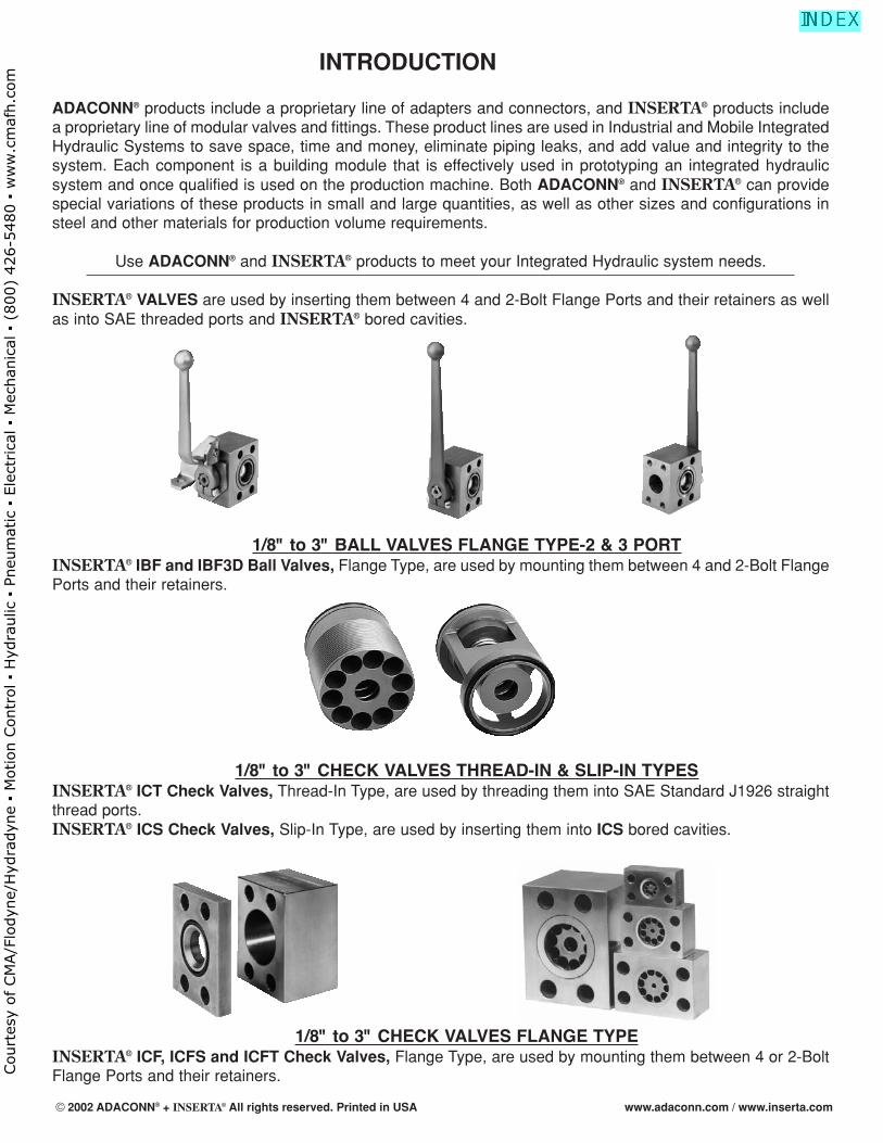
INTRODUCTION
ADACONN® products include a proprietary line of adapters and connectors, and INSERTA® products includea proprietary line of modular valves and fittings. These product lines are used in Industrial and Mobile IntegratedHydraulic Systems to save space, time and money, eliminate piping leaks, and add value and integrity to thesystem. Each component is a building module that is effectively used in prototyping an integrated hydraulicsystem and once qualified is used on the production machine. Both ADACONN® and INSERTA® can providespecial variations of these products in small and large quantities, as well as other sizes and configurations insteel and other materials for production volume requirements.
Use ADACONN® and INSERTA® products to meet your Integrated Hydraulic system needs.
INSERTA® VALVES are used by inserting them between 4 and 2-Bolt Flange Ports and their retainers as wellas into SAE threaded ports and INSERTA® bored cavities.
1/8" to 3" BALL VALVES FLANGE TYPE-2 & 3 PORTINSERTA® IBF and IBF3D Ball Valves, Flange Type, are used by mounting them between 4 and 2-Bolt FlangePorts and their retainers.
1/8" to 3" CHECK VALVES THREAD-IN & SLIP-IN TYPESINSERTA® ICT Check Valves, Thread-In Type, are used by threading them into SAE Standard J1926 straightthread ports.INSERTA® ICS Check Valves, Slip-In Type, are used by inserting them into ICS bored cavities.
1/8" to 3" CHECK VALVES FLANGE TYPEINSERTA® ICF, ICFS and ICFT Check Valves, Flange Type, are used by mounting them between 4 or 2-BoltFlange Ports and their retainers.
© 2002 ADACONN® + INSERTA® All rights reserved. Printed in USA www.adaconn.com / www.inserta.com
Court
esy
of CM
A/F
lodyn
e/H
ydra
dyn
e ▪
Motion C
ontr
ol ▪
Hyd
raulic
▪ P
neu
mat
ic ▪
Ele
ctrica
l ▪
Mec
han
ical
▪ (
800)
426-5
480 ▪
ww
w.c
maf
h.c
om
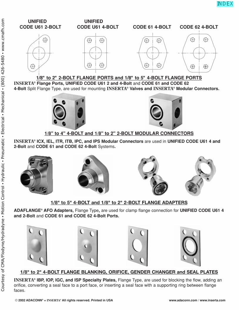
UNIFIED UNIFIEDCODE U61 2-BOLT CODE U61 4-BOLT CODE 61 4-BOLT CODE 62 4-BOLT
1/8" to 2" 2-BOLT FLANGE PORTS and 1/8" to 5" 4-BOLT FLANGE PORTSINSERTA® Flange Ports, UNIFIED CODE U61 2 and 4-Bolt and CODE 61 and CODE 624-Bolt Split Flange Type, are used for mounting INSERTA® Valves and INSERTA® Modular Connectors.
1/8" to 4" 4-BOLT and 1/8" to 2" 2-BOLT MODULAR CONNECTORS
INSERTA® ICX, IEL, ITR, ITB, IPC, and IPS Modular Connectors are used in UNIFIED CODE U61 4 and2-Bolt and CODE 61 and CODE 62 4-Bolt Systems.
1/8" to 5" 4-BOLT and 1/8" to 2" 2-BOLT FLANGE ADAPTERS
ADAFLANGE® AFO Adapters, Flange Type, are used for clamp flange connection for UNIFIED CODE U61 4and 2-Bolt and CODE 61 and CODE 62 4-Bolt Ports.
1/8" to 2" 4-BOLT FLANGE BLANKING, ORIFICE, GENDER CHANGER and SEAL PLATES
INSERTA® IBP, IOP, IGC, and ISP Specialty Plates, Flange Type, are used for blocking the flow, adding anorifice, converting a seal face to a port face, or inserting a seal face with a supporting ring between flangefaces.
ii© 2002 ADACONN® + INSERTA® All rights reserved. Printed in USA www.adaconn.com / www.inserta.com
Court
esy
of CM
A/F
lodyn
e/H
ydra
dyn
e ▪
Motion C
ontr
ol ▪
Hyd
raulic
▪ P
neu
mat
ic ▪
Ele
ctrica
l ▪
Mec
han
ical
▪ (
800)
426-5
480 ▪
ww
w.c
maf
h.c
om
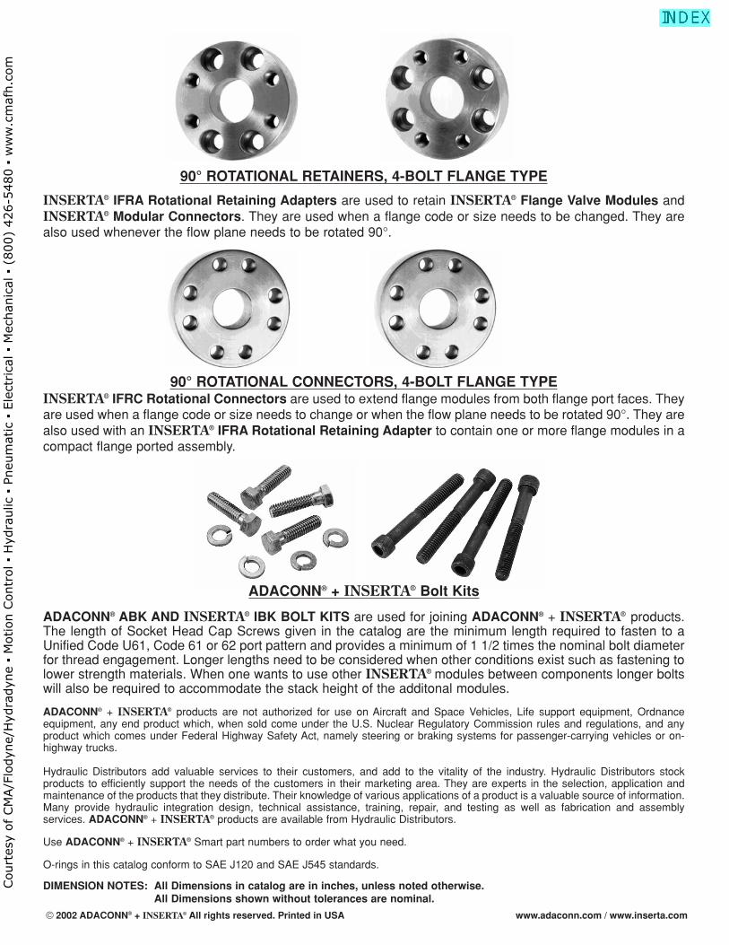
90° ROTATIONAL RETAINERS, 4-BOLT FLANGE TYPE
INSERTA® IFRA Rotational Retaining Adapters are used to retain INSERTA® Flange Valve Modules andINSERTA® Modular Connectors. They are used when a flange code or size needs to be changed. They arealso used whenever the flow plane needs to be rotated 90°.
90° ROTATIONAL CONNECTORS, 4-BOLT FLANGE TYPEINSERTA® IFRC Rotational Connectors are used to extend flange modules from both flange port faces. Theyare used when a flange code or size needs to change or when the flow plane needs to be rotated 90°. They arealso used with an INSERTA® IFRA Rotational Retaining Adapter to contain one or more flange modules in acompact flange ported assembly.
ADACONN® + INSERTA® Bolt Kits
ADACONN® ABK AND INSERTA® IBK BOLT KITS are used for joining ADACONN® + INSERTA® products.The length of Socket Head Cap Screws given in the catalog are the minimum length required to fasten to aUnified Code U61, Code 61 or 62 port pattern and provides a minimum of 1 1/2 times the nominal bolt diameterfor thread engagement. Longer lengths need to be considered when other conditions exist such as fastening tolower strength materials. When one wants to use other INSERTA® modules between components longer boltswill also be required to accommodate the stack height of the additonal modules.
ADACONN® + INSERTA® products are not authorized for use on Aircraft and Space Vehicles, Life support equipment, Ordnanceequipment, any end product which, when sold come under the U.S. Nuclear Regulatory Commission rules and regulations, and anyproduct which comes under Federal Highway Safety Act, namely steering or braking systems for passenger-carrying vehicles or on-highway trucks.
Hydraulic Distributors add valuable services to their customers, and add to the vitality of the industry. Hydraulic Distributors stockproducts to efficiently support the needs of the customers in their marketing area. They are experts in the selection, application andmaintenance of the products that they distribute. Their knowledge of various applications of a product is a valuable source of information.Many provide hydraulic integration design, technical assistance, training, repair, and testing as well as fabrication and assemblyservices. ADACONN® + INSERTA® products are available from Hydraulic Distributors.
Use ADACONN® + INSERTA® Smart part numbers to order what you need.
O-rings in this catalog conform to SAE J120 and SAE J545 standards.
DIMENSION NOTES: All Dimensions in catalog are in inches, unless noted otherwise.All Dimensions shown without tolerances are nominal.
© 2002 ADACONN® + INSERTA® All rights reserved. Printed in USA www.adaconn.com / www.inserta.com
Court
esy
of CM
A/F
lodyn
e/H
ydra
dyn
e ▪
Motion C
ontr
ol ▪
Hyd
raulic
▪ P
neu
mat
ic ▪
Ele
ctrica
l ▪
Mec
han
ical
▪ (
800)
426-5
480 ▪
ww
w.c
maf
h.c
om
® ®
® ®
® ®
Blue Bell, PA 19422® ®
USE THE
ALTERNATIVES
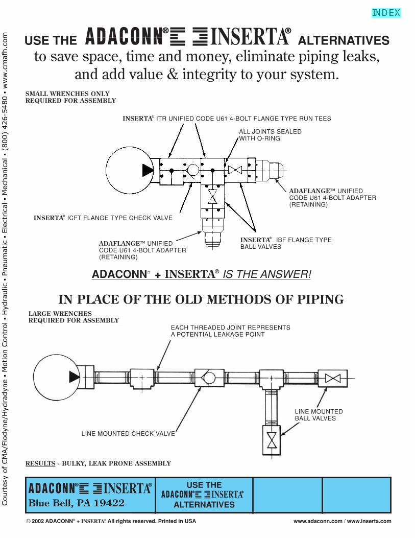
USE THE ALTERNATIVESto save space, time and money, eliminate piping leaks,
and add value & integrity to your system.
® ®
OR
OR
OR
AND
OR
OR
OR
AN
DADACONN¤ + INSERTA® IS THE ANSWER!
IN PLACE OF THE OLD METHODS OF PIPING
EACH THREADED JOINT REPRESENTSA POTENTIAL LEAKAGE POINT
LINE MOUNTED CHECK VALVE
LINE MOUNTEDBALL VALVES
LARGE WRENCHESREQUIRED FOR ASSEMBLY
RESULTS - BULKY, LEAK PRONE ASSEMBLY
SMALL WRENCHES ONLYREQUIRED FOR ASSEMBLY
ALL JOINTS SEALEDWITH O-RING
INSERTA® ITR UNIFIED CODE U61 4-BOLT FLANGE TYPE RUN TEES
ADAFLANGETM UNIFIED CODE U61 4-BOLT ADAPTER(RETAINING)
INSERTA® ICFT FLANGE TYPE CHECK VALVE
INSERTA® IBF FLANGE TYPEBALL VALVES ADAFLANGETM UNIFIED
CODE U61 4-BOLT ADAPTER(RETAINING)
© 2002 ADACONN® + INSERTA® All rights reserved. Printed in USA www.adaconn.com / www.inserta.com
Court
esy
of CM
A/F
lodyn
e/H
ydra
dyn
e ▪
Motion C
ontr
ol ▪
Hyd
raulic
▪ P
neu
mat
ic ▪
Ele
ctrica
l ▪
Mec
han
ical
▪ (
800)
426-5
480 ▪
ww
w.c
maf
h.c
om
® ®
Blue Bell, PA 19422® ®
USE THE
ALTERNATIVES
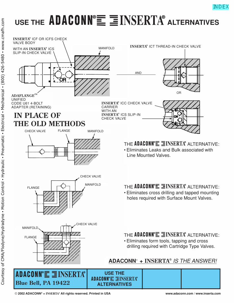
THE ALTERNATIVE:• Eliminates Leaks and Bulk associated with
Line Mounted Valves.
® ®
THE ALTERNATIVE:• Eliminates cross drilling and tapped mounting
holes required with Surface Mount Valves.
® ®
THE ALTERNATIVE:• Eliminates form tools, tapping and cross
drilling required with Cartridge Type Valves.
® ®
OROR
OR
OR
AND AND
OR
IN PLACE OF THE OLD METHODS
INSERTA® ICF OR ICFS CHECKVALVE BODY
WITH AN INSERTA® ICS SLIP-IN CHECK VALVE
ADAFLANGETM
UNIFIEDCODE U61 4-BOLTADAPTER (RETAINING)
USE THE ALTERNATIVES® ®
INSERTA® ICT THREAD-IN CHECK VALVE
CHECK VALVE FLANGE MANIFOLD
CHECK VALVE
MANIFOLDFLANGE
FLANGE
MANIFOLDCHECK VALVE
MANIFOLD
ADACONN¤ + INSERTA® IS THE ANSWER!
INSERTA® ICC CHECK VALVECARRIER WITH AN INSERTA® ICS SLIP-INCHECK VALVE
© 2002 ADACONN® + INSERTA® All rights reserved. Printed in USA www.adaconn.com / www.inserta.com
Court
esy
of CM
A/F
lodyn
e/H
ydra
dyn
e ▪
Motion C
ontr
ol ▪
Hyd
raulic
▪ P
neu
mat
ic ▪
Ele
ctrica
l ▪
Mec
han
ical
▪ (
800)
426-5
480 ▪
ww
w.c
maf
h.c
om
Inserta Products, Inc.Blue Bell, Pa. 19422
BALL VALVESFLANGE TYPE
2 PORT
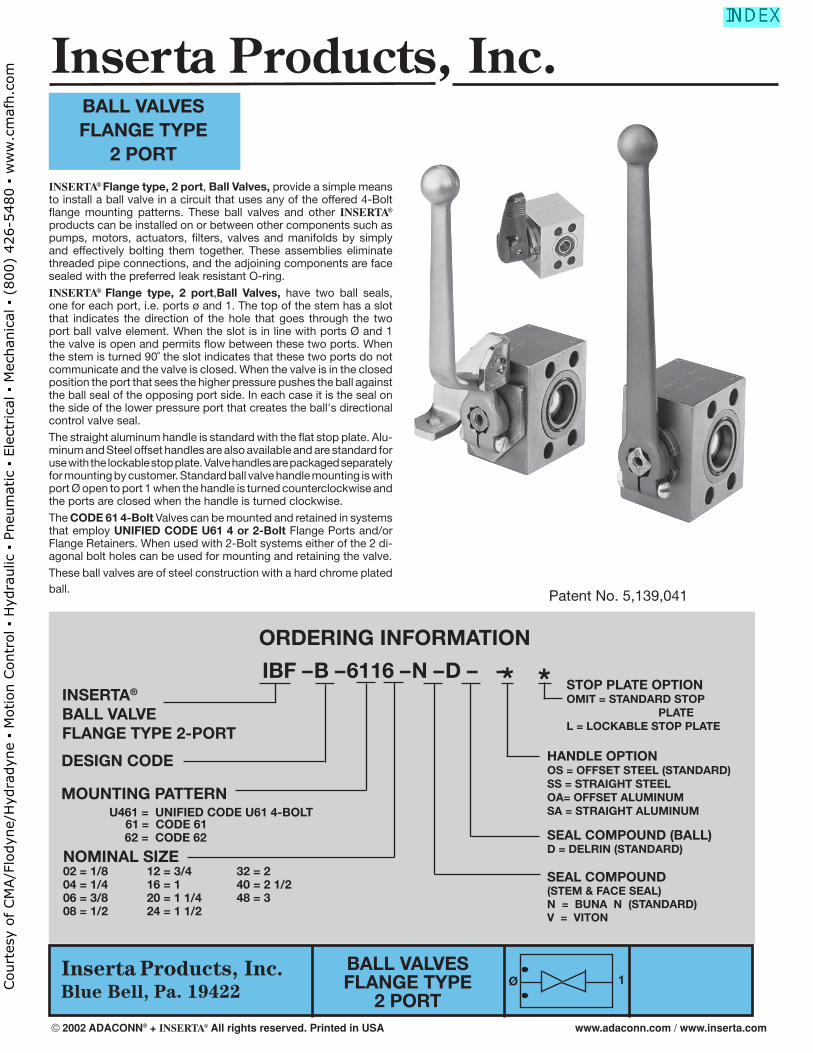
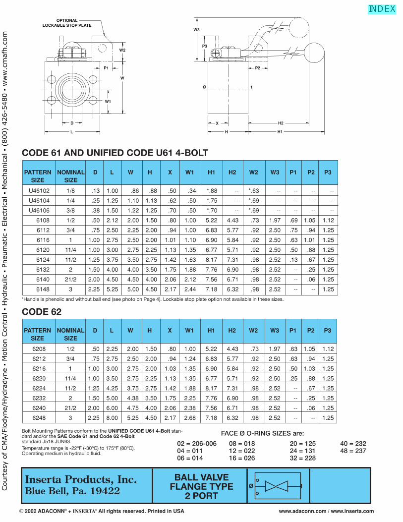
INSERTA® Flange type, 2 port, Ball Valves, provide a simple means to install a ball valve in a circuit that uses any of the offered 4-Bolt fl ange mounting patterns. These ball valves and other INSERTA® products can be installed on or between other components such as pumps, motors, actuators, fi lters, valves and manifolds by simply and effectively bolting them together. These assemblies eliminate threaded pipe connections, and the adjoining components are face sealed with the preferred leak resistant O-ring.
INSERTA® Flange type, 2 port,Ball Valves, have two ball seals, one for each port, i.e. ports ø and 1. The top of the stem has a slot that indicates the direction of the hole that goes through the two port ball valve element. When the slot is in line with ports Ø and 1 the valve is open and permits fl ow between these two ports. When the stem is turned 90˚ the slot indicates that these two ports do not communicate and the valve is closed. When the valve is in the closed position the port that sees the higher pressure pushes the ball against the ball seal of the opposing port side. In each case it is the seal on the side of the lower pressure port that creates the ball's directional control valve seal.
The straight aluminum handle is standard with the fl at stop plate. Alu-minum and Steel offset handles are also available and are standard for use with the lockable stop plate. Valve handles are packaged separately for mounting by customer. Standard ball valve handle mounting is with port Ø open to port 1 when the handle is turned counterclockwise and the ports are closed when the handle is turned clockwise.
The CODE 61 4-Bolt Valves can be mounted and retained in systems that employ UNIFIED CODE U61 4 or 2-Bolt Flange Ports and/or Flange Retainers. When used with 2-Bolt systems either of the 2 di-agonal bolt holes can be used for mounting and retaining the valve.
These ball valves are of steel construction with a hard chrome plated ball.
ORDERING INFORMATION
* * IBF – B – 6116 – N – D – – INSERTA®
BALL VALVEFLANGE TYPE 2-PORT
DESIGN CODE
MOUNTING PATTERN U461 = UNIFIED CODE U61 4-BOLT 61 = CODE 61 62 = CODE 62
NOMINAL SIZE02 = 1/8 12 = 3/4 32 = 2 04 = 1/4 16 = 1 40 = 2 1/206 = 3/8 20 = 1 1/4 48 = 308 = 1/2 24 = 1 1/2
SEAL COMPOUND(STEM & FACE SEAL)N = BUNA N (STANDARD)V = VITON
SEAL COMPOUND (BALL)D = DELRIN (STANDARD)
HANDLE OPTIONOS = OFFSET STEEL (STANDARD) SS = STRAIGHT STEELOA= OFFSET ALUMINUMSA = STRAIGHT ALUMINUM
STOP PLATE OPTIONOMIT = STANDARD STOP PLATEL = LOCKABLE STOP PLATE
Patent No. 5,139,041
Ø 1
BALL VALVESFLANGE TYPE
2 PORT
Inserta Products, Inc.
© 2002 ADACONN® + INSERTA® All rights reserved. Printed in USA www.adaconn.com / www.inserta.com
Court
esy
of CM
A/F
lodyn
e/H
ydra
dyn
e ▪
Motion C
ontr
ol ▪
Hyd
raulic
▪ P
neu
mat
ic ▪
Ele
ctrica
l ▪
Mec
han
ical
▪ (
800)
426-5
480 ▪
ww
w.c
maf
h.c
om
6208 1/2 .50 2.25 2.00 1.50 .80 1.00 5.22 4.43 .73 1.97 .63 1.05 1.12
6212 3/4 .75 2.75 2.50 2.00 .94 1.24 6.83 5.77 .92 2.50 .63 .94 1.25
6216 1 1.00 3.00 2.75 2.00 1.03 1.35 6.90 5.84 .92 2.50 .50 1.03 1.25
6220 11/4 1.00 3.50 2.75 2.25 1.13 1.35 6.77 5.71 .92 2.50 .25 .88 1.25
6224 11/2 1.25 4.25 3.75 2.75 1.42 1.88 8.17 7.31 .98 2.52 -- .67 1.25
6232 2 1.50 5.00 4.38 3.50 1.75 2.25 7.76 6.90 .98 2.52 -- .25 1.25
6240 21/2 2.00 6.00 4.75 4.00 2.06 2.38 7.56 6.71 .98 2.52 -- .06 1.25
6248 3 2.25 8.00 5.25 4.50 2.17 2.68 7.18 6.32 .98 2.52 -- -- 1.25
PATTERN NOMINAL D L W H X W1 H1 H2 W2 W3 P1 P2 P3SIZE SIZE
Inserta Products, Inc.Blue Bell, Pa. 19422
CODE 61 AND UNIFIED CODE U61 4-BOLT
BALL VALVEFLANGE TYPE
2 PORT
FACE Ø O-RING SIZES are:
02 = 206-006 08 = 018 20 = 125 40 = 232 04 = 011 12 = 022 24 = 131 48 = 237 06 = 014 16 = 026 32 = 228
Bolt Mounting Patterns conform to the UNIFIED CODE U61 4-Bolt stan-dard and/or the SAE Code 61 and Code 62 4-Bolt standard J518 JUN93.Temperature range is -22ºF (-30ºC) to 175ºF (80ºC). Operating medium is hydraulic fl uid.
*Handle is phenolic and without ball end (see photo on Page 4). Lockable stop plate option not available in these sizes.
Ø 1
OPTIONALLOCKABLE STOP PLATE
W2
W
P1
W1
D
L
W3
P3
H
X
1Ø
P2
H2
H1
U46102 1/8 .13 1.00 .86 .88 .50 .34 *.88 -- *.63 -- -- -- --
U46104 1/4 .25 1.25 1.10 1.13 .62 .50 *.75 -- *.69 -- -- -- --
U46106 3/8 .38 1.50 1.22 1.25 .70 .50 *.70 -- *.69 -- -- -- --
6108 1/2 .50 2.12 2.00 1.50 .80 1.00 5.22 4.43 .73 1.97 .69 1.05 1.12
6112 3/4 .75 2.50 2.25 2.00 .94 1.00 6.83 5.77 .92 2.50 .75 .94 1.25
6116 1 1.00 2.75 2.50 2.00 1.01 1.10 6.90 5.84 .92 2.50 .63 1.01 1.25
6120 11/4 1.00 3.00 2.75 2.25 1.13 1.35 6.77 5.71 .92 2.50 .50 .88 1.25
6124 11/2 1.25 3.75 3.50 2.75 1.42 1.63 8.17 7.31 .98 2.52 .13 .67 1.25
6132 2 1.50 4.00 4.00 3.50 1.75 1.88 7.76 6.90 .98 2.52 -- .25 1.25
6140 21/2 2.00 4.50 4.50 4.00 2.06 2.12 7.56 6.71 .98 2.52 -- .06 1.25
6148 3 2.25 5.25 5.00 4.50 2.17 2.44 7.18 6.32 .98 2.52 -- -- 1.25
PATTERN NOMINAL D L W H X W1 H1 H2 W2 W3 P1 P2 P3SIZE SIZE
CODE 62
© 2002 ADACONN® + INSERTA® All rights reserved. Printed in USA www.adaconn.com / www.inserta.com
Court
esy
of CM
A/F
lodyn
e/H
ydra
dyn
e ▪
Motion C
ontr
ol ▪
Hyd
raulic
▪ P
neu
mat
ic ▪
Ele
ctrica
l ▪
Mec
han
ical
▪ (
800)
426-5
480 ▪
ww
w.c
maf
h.c
om
Inserta Products, Inc.Blue Bell, Pa. 19422
Inserta Products, Inc.
BALL VALVESFLANGE TYPE
3 PORT DIVERTER
BALL VALVESFLANGE TYPE
3 PORT DIVERTER
ORDERING INFORMATION
* * IBF3D – A – 6116 – N – D – – INSERTA®
BALL VALVE FLANGE TYPE3 PORT DIVERTER
DESIGN CODE
SEAL COMPOUND(STEM & FACE SEAL)N = BUNA N (STANDARD)V = VITON
SEAL COMPOUND (BALL)D = DELRIN (STANDARD)
STOP PLATE OPTIONOMIT = STANDARD STOP PLATEL = LOCKABLE STOP PLATE
Patent No. 5,139,041
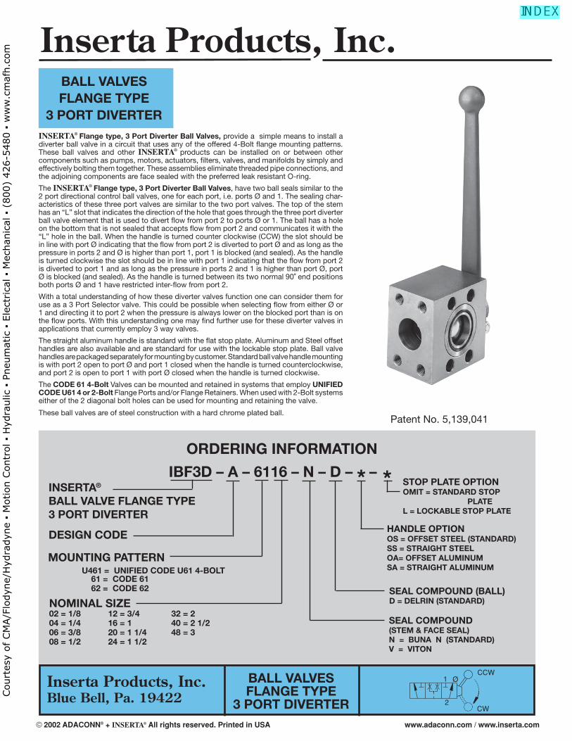
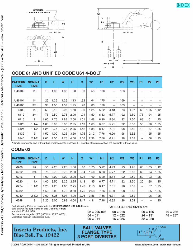
INSERTA® Flange type, 3 Port Diverter Ball Valves, provide a simple means to install a diverter ball valve in a circuit that uses any of the offered 4-Bolt fl ange mounting patterns. These ball valves and other INSERTA® products can be installed on or between other components such as pumps, motors, actuators, fi lters, valves, and manifolds by simply and effectively bolting them together. These assemblies eliminate threaded pipe connections, and the adjoining components are face sealed with the preferred leak resistant O-ring.
The INSERTA® Flange type, 3 Port Diverter Ball Valves, have two ball seals similar to the 2 port directional control ball valves, one for each port, i.e. ports Ø and 1. The sealing char-acteristics of these three port valves are similar to the two port valves. The top of the stem has an “L” slot that indicates the direction of the hole that goes through the three port diverter ball valve element that is used to divert fl ow from port 2 to ports Ø or 1. The ball has a hole on the bottom that is not sealed that accepts fl ow from port 2 and communicates it with the “L” hole in the ball. When the handle is turned counter clockwise (CCW) the slot should be in line with port Ø indicating that the fl ow from port 2 is diverted to port Ø and as long as the pressure in ports 2 and Ø is higher than port 1, port 1 is blocked (and sealed). As the handle is turned clockwise the slot should be in line with port 1 indicating that the fl ow from port 2 is diverted to port 1 and as long as the pressure in ports 2 and 1 is higher than port Ø, port Ø is blocked (and sealed). As the handle is turned between its two normal 90˚ end positions both ports Ø and 1 have restricted inter-fl ow from port 2.
With a total understanding of how these diverter valves function one can consider them for use as a 3 Port Selector valve. This could be possible when selecting fl ow from either Ø or 1 and directing it to port 2 when the pressure is always lower on the blocked port than is on the fl ow ports. With this understanding one may fi nd further use for these diverter valves in applications that currently employ 3 way valves.
The straight aluminum handle is standard with the fl at stop plate. Aluminum and Steel offset handles are also available and are standard for use with the lockable stop plate. Ball valve handles are packaged separately for mounting by customer. Standard ball valve handle mounting is with port 2 open to port Ø and port 1 closed when the handle is turned counterclockwise, and port 2 is open to port 1 with port Ø closed when the handle is turned clockwise.
The CODE 61 4-Bolt Valves can be mounted and retained in systems that employ UNIFIED CODE U61 4 or 2-Bolt Flange Ports and/or Flange Retainers. When used with 2-Bolt systems either of the 2 diagonal bolt holes can be used for mounting and retaining the valve.
These ball valves are of steel construction with a hard chrome plated ball.
MOUNTING PATTERN U461 = UNIFIED CODE U61 4-BOLT 61 = CODE 61 62 = CODE 62 NOMINAL SIZE02 = 1/8 12 = 3/4 32 = 2 04 = 1/4 16 = 1 40 = 2 1/206 = 3/8 20 = 1 1/4 48 = 308 = 1/2 24 = 1 1/2
CCW
CW
1
2
Ø
HANDLE OPTIONOS = OFFSET STEEL (STANDARD) SS = STRAIGHT STEELOA= OFFSET ALUMINUMSA = STRAIGHT ALUMINUM
© 2002 ADACONN® + INSERTA® All rights reserved. Printed in USA www.adaconn.com / www.inserta.com
Court
esy
of CM
A/F
lodyn
e/H
ydra
dyn
e ▪
Motion C
ontr
ol ▪
Hyd
raulic
▪ P
neu
mat
ic ▪
Ele
ctrica
l ▪
Mec
han
ical
▪ (
800)
426-5
480 ▪
ww
w.c
maf
h.c
om
U46102 1/8 .13 1.00 1.08 .88 .50 .56 *.88 -- *.63 -- -- -- --
U46104 1/4 .25 1.25 1.25 1.13 .62 .64 *.75 -- *.69 -- -- -- --
U46106 3/8 .38 1.50 1.59 1.25 .70 .86 *.70 -- *.69 -- -- -- --
6108 1/2 .50 2.12 2.25 1.50 .80 1.25 5.22 4.43 .73 1.97 .69 1.05 1.12
6112 3/4 .75 2.50 2.75 2.00 .94 1.50 6.83 5.77 .92 2.50 .75 .94 1.25
6116 1 1.00 2.75 2.88 2.00 1.01 1.48 6.90 5.84 .92 2.50 .63 1.01 1.25
6120 1 1/4 1.00 3.00 3.00 2.25 1.13 1.60 6.77 5.71 .92 2.50 .50 .88 1.25
6124 1 1/2 1.25 3.75 3.75 2.75 1.42 1.88 8.17 7.31 .98 2.52 .13 .67 1.25
6132 2 1.50 4.00 4.25 3.50 1.75 2.12 7.76 6.90 .98 2.52 -- .25 1.25
6140 2 1/2 2.00 4.50 4.75 4.00 2.06 2.38 7.56 6.71 .98 2.52 -- .06 1.25
PATTERN NOMINAL D L W H X W1 H1 H2 W2 W3 P1 P2 P3SIZE SIZE
Inserta Products, Inc.Blue Bell, Pa. 19422
CODE 61 AND UNIFIED CODE U61 4-BOLT
BALL VALVESFLANGE TYPE
3 PORT DIVERTER
Bolt Mounting Patterns conform to the UNIFIED CODE U61 4-Bolt stan-dard and/or the SAE Code 61 and Code 62 4-Bolt standard J518 JUN93.Temperature range is -22ºF (-30ºC) to 175ºF (80ºC). Operating medium is hydraulic fl uid.
*Handle is phenolic and without ball end (see photo on Page 4). Lockable stop plate option not available in these sizes.
FACE Ø O-RING SIZES are:
02 = 206-006 08 = 018 20 = 125 40 = 232 04 = 011 12 = 022 24 = 131 48 = 237 06 = 014 16 = 026 32 = 228
2
OPTIONALLOCKABLE STOP PLATE
W2
W
P1
W1
D
L
W3
P3
H
X
1Ø
P2
H2
H1
D
6208 1/2 .50 2.25 2.25 1.50 .80 1.25 5.22 4.43 .73 1.97 .63 1.05 1.12
6212 3/4 .75 2.75 2.75 2.00 .94 1.50 6.83 5.77 .92 2.50 .63 .94 1.25
6216 1 1.00 3.00 3.00 2.00 1.03 1.60 6.90 5.84 .92 2.50 .50 1.03 1.25
6220 1 1/4 1.00 3.50 3.25 2.25 1.13 1.85 6.77 5.71 .92 2.50 .25 .88 1.25
6224 1 1/2 1.25 4.25 4.00 2.75 1.42 2.13 8.17 7.31 .98 2.52 -- .67 1.25
6232 2 1.50 5.00 4.75 3.50 1.75 2.63 7.76 6.90 .98 2.52 -- .25 1.25
6240 2 1/2 2.00 6.25 5.94 4.00 2.06 3.56 7.56 6.71 .98 2.52 -- .06 1.25
6248 3 2.25 8.00 6.88 4.50 2.17 4.31 7.18 6.32 .98 2.52 -- -- 1.25
PATTERN NOMINAL D L W H X W1 H1 H2 W2 W3 P1 P2 P3SIZE SIZE
CODE 62
CCW
CW
1
2
Ø
© 2002 ADACONN® + INSERTA® All rights reserved. Printed in USA www.adaconn.com / www.inserta.com
Court
esy
of CM
A/F
lodyn
e/H
ydra
dyn
e ▪
Motion C
ontr
ol ▪
Hyd
raulic
▪ P
neu
mat
ic ▪
Ele
ctrica
l ▪
Mec
han
ical
▪ (
800)
426-5
480 ▪
ww
w.c
maf
h.c
om
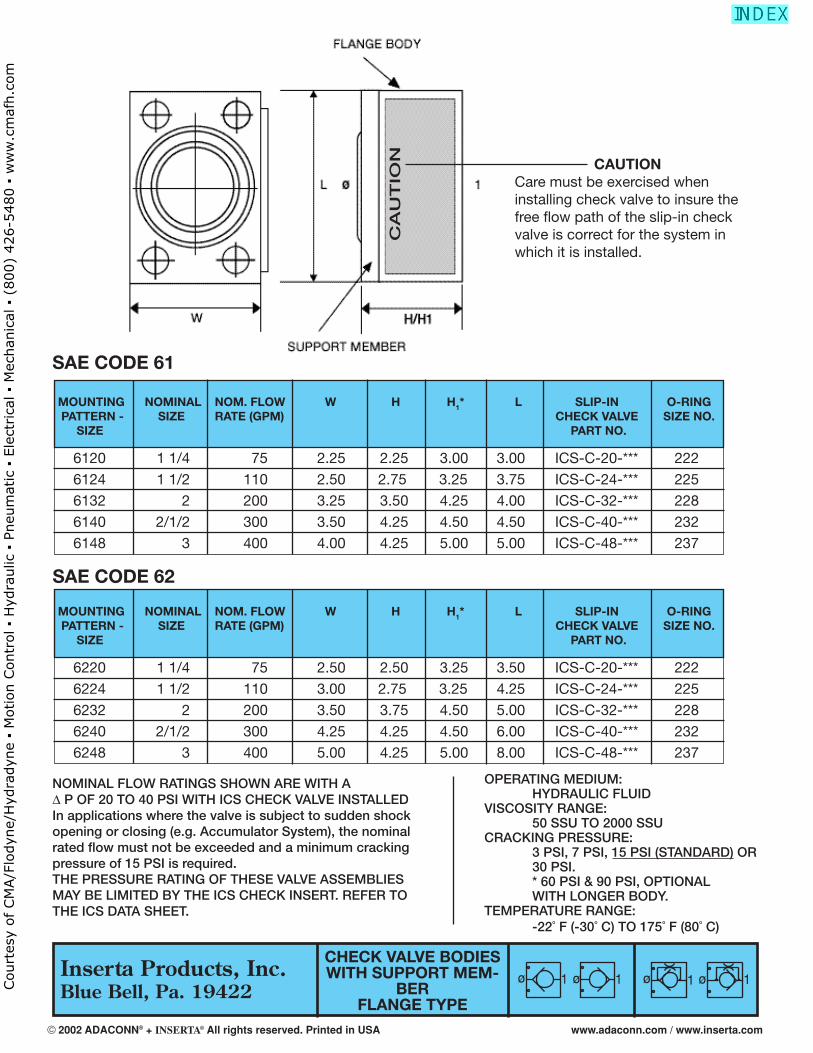
CHECK VALVESSLIP-IN TYPE
Inserta Products, Inc.Blue Bell, Pa. 19422
CRACKING PRESSURE 03 = 3 PSI 07 = 7 PSI 15 = 15 PSI (STANDARD) 30 = 30 PSI 60 = 60 PSI 90 = 90 PSI
SEAL COMPOUND N = BUNA-N (STANDARD) V = VITON
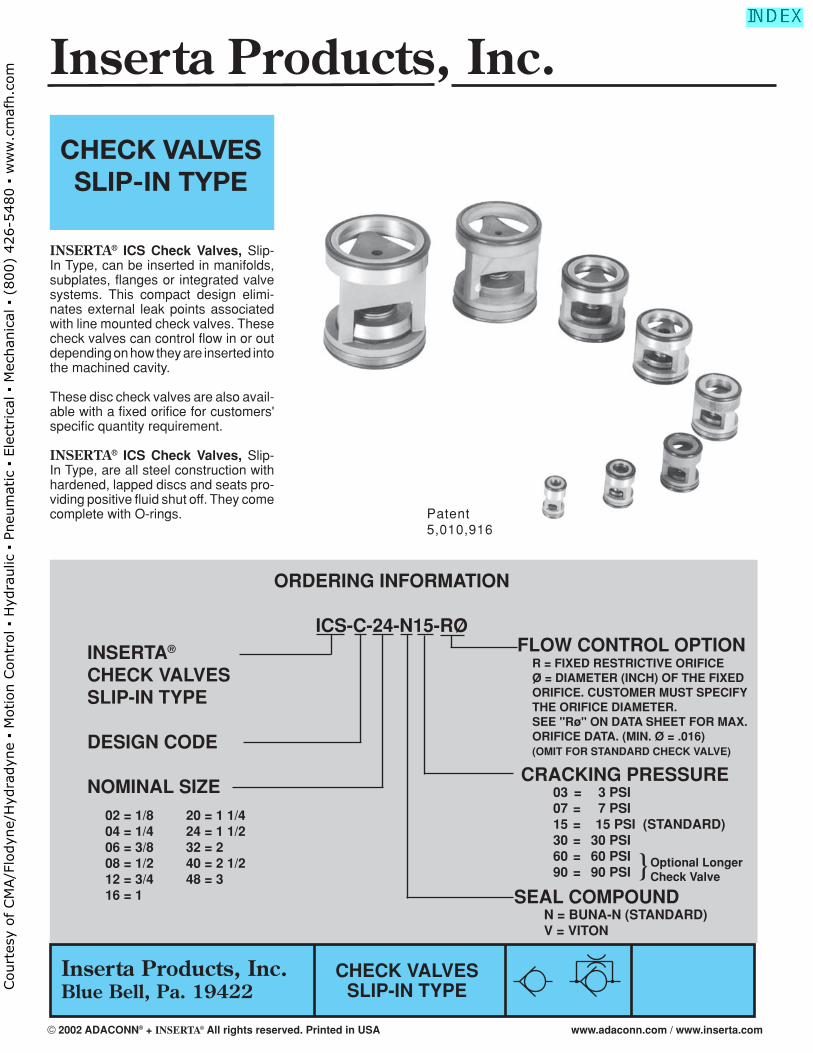
INSERTA® ICS Check Valves, Slip-In Type, can be inserted in manifolds, subplates, fl anges or integrated valve systems. This compact design elimi-nates external leak points associated with line mounted check valves. These check valves can control fl ow in or out depending on how they are inserted into the machined cavity.
These disc check valves are also avail-able with a fi xed orifi ce for customers' specifi c quantity requirement.
INSERTA® ICS Check Valves, Slip-In Type, are all steel construction with hardened, lapped discs and seats pro-viding positive fl uid shut off. They come complete with O-rings.
INSERTA®
CHECK VALVESSLIP-IN TYPE
DESIGN CODE
NOMINAL SIZE
02 = 1/8 20 = 1 1/4 04 = 1/4 24 = 1 1/206 = 3/8 32 = 208 = 1/2 40 = 2 1/212 = 3/4 48 = 316 = 1
ORDERING INFORMATION
ICS-C-24-N15-RO
CHECK VALVESSLIP-IN TYPE
}Optional LongerCheck Valve
Patent5,010,916
FLOW CONTROL OPTION R = FIXED RESTRICTIVE ORIFICE O = DIAMETER (INCH) OF THE FIXED ORIFICE. CUSTOMER MUST SPECIFY THE ORIFICE DIAMETER. SEE "Rø" ON DATA SHEET FOR MAX. ORIFICE DATA. (MIN. Ø = .016) (OMIT FOR STANDARD CHECK VALVE)
Inserta Products, Inc.
© 2002 ADACONN® + INSERTA® All rights reserved. Printed in USA www.adaconn.com / www.inserta.com
Court
esy
of CM
A/F
lodyn
e/H
ydra
dyn
e ▪
Motion C
ontr
ol ▪
Hyd
raulic
▪ P
neu
mat
ic ▪
Ele
ctrica
l ▪
Mec
han
ical
▪ (
800)
426-5
480 ▪
ww
w.c
maf
h.c
om
Inserta Products, Inc.Blue Bell, Pa. 19422
CHECK VALVESSLIP-IN TYPE
In applications where the valve is subject to sudden shock opening or closing(e.g. Accumulator System), the nominal rated fl ow must not be exceeded and a minimum cracking pressure of 15 PSI is required.
NOMINAL FLOW RATES ARE WITH A P OF
20 TO 40 PSI
MOUNTING POSITION: OPTIONALMAXIMUM OPERATING PRESSURE: 5000 PSI (Contact the Factory for pressures up to 7250 PSI)TEMPERATURE RANGE: –22°F (–30°C) To 175°F (80°C)OPERATING MEDIUM: HYDRAULIC FLUID
VALVE NOMINAL A B B1* Rø 0-RING SIZE SIZE FLOW (GPM) –.002 –.002 –.002 MAX NO. (mm)
02 2 .333 .531 .728 .024 (6.2 x 1.0) 04 5 .451 .571 .846 .039 (8.5 x 1.5) 06 10 .589 .669 .866 .078 (12.0 x 1.5) 08 18 .746 .787 .945 .078 (16.0 x 1.5) 12 24 .963 .906 1.220 .140 116 16 45 1.199 1.102 1.535 .218 213 20 75 1.553 1.653 2.434 .315 219 24 110 1.770 2.007 2.500 .394 222 32 200 2.391 2.858 3.582 .394 227 40 300 2.883 3.407 3.532 .394 231 48 400 3.385 3.507 4.119 .394 235
CAUTIONCare must be exercised when installing check valve to insure the free fl ow path of the slip-in check valve is correct for the system in which it is installed.
02 .3346 / .3360 .433 .157 .197 .531 .728 .220 04 .4528 / .4545 .551 .236 .236 .571 .846 .256 06 .5906 / .5923 .709 .315 .354 .669 .866 .374 08 .7480 / .7500 .866 .433 .433 .787 .945 .453 12 .9646 / .9666 1.102 .591 .551 .906 1.220 .571 16 1.2008 / 1.2032 1.378 .787 .787 1.102 1.535 .787 20 1.5551 / 1.5575 1.811 1.031 1.102 1.653 2.434 1.102 24 1.7717 / 1.7741 2.204 1.250 1.250 2.007 2.500 1.375 32 2.3927 / 2.3960 2.968 1.750 1.750 2.858 3.582 1.875 40 2.884 / 2.887 3.546 2.062 2.062 3.407 3.532 1.750 48 3.386 / 3.389 4.203 2.500 2.500 3.507 4.119 2.000
VALVE G H J K L L1* M SIZE MAX. MAX. MAX. +.002 +.002 MAX. –.000 –.000
VISCOSITY RANGE: 50 SSU TO 2000 SSUCRACKING PRESSURE: 3 PSI, 7 PSI, 15 PSI (STANDARD) OR 30 PSI. * 60 PSI & 90 PSI, OPTIONAL WITH LONGER CHECK VALVE.
NOTE: MINIMUM ORIFICE=.016 DIAMETER
© 2002 ADACONN® + INSERTA® All rights reserved. Printed in USA www.adaconn.com / www.inserta.com
Court
esy
of CM
A/F
lodyn
e/H
ydra
dyn
e ▪
Motion C
ontr
ol ▪
Hyd
raulic
▪ P
neu
mat
ic ▪
Ele
ctrica
l ▪
Mec
han
ical
▪ (
800)
426-5
480 ▪
ww
w.c
maf
h.c
om
Inserta Products, Inc.Blue Bell, Pa. 19422
ORDERING INFORMATION
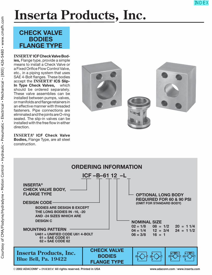
ICF – B– 61 12 – L
CHECK VALVEBODIES
FLANGE TYPE
INSERTA® ICF Check Valve Bod-ies, Flange type, provide a simple means to install a Check Valve or a Fixed Orifi ce Flow Control Valve, etc., in a piping system that uses SAE 4-Bolt fl anges. These bodies accept the INSERTA® ICS Slip-In Type Check Valves, which should be ordered separately. These valve assemblies can be installed between pumps, valves, or manifolds and fl ange retainers in an effective manner with threaded fasteners. Pipe connections are eliminated and the joints are O-ring sealed. The slip-in valves can be installed with the free fl ow in either direction.
INSERTA® ICF Check Valve Bodies, Flange Type, are all steel construction.
CHECK VALVE BODIES
FLANGE TYPE
INSERTA®
CHECK VALVE BODY,FLANGE TYPE
DESIGN CODE BODIES ARE DESIGN B EXCEPT THE LONG BODIES IN -16, -20 AND -24 SIZES WHICH ARE DESIGN C
MOUNTING PATTERN U461 = UNIFIED CODE U61 4-BOLT 61 = SAE CODE 61 62 = SAE CODE 62
NOMINAL SIZE02 = 1/8 08 = 1/2 20 = 1 1/404 = 1/4 12 = 3/4 24 = 1 1/206 = 3/8 16 = 1
OPTIONAL LONG BODYREQUIRED FOR 60 & 90 PSI(OMIT FOR STANDARD BODY)
ø ø1 1 ø ø1 1
Inserta Products, Inc.
© 2002 ADACONN® + INSERTA® All rights reserved. Printed in USA www.adaconn.com / www.inserta.com
Court
esy
of CM
A/F
lodyn
e/H
ydra
dyn
e ▪
Motion C
ontr
ol ▪
Hyd
raulic
▪ P
neu
mat
ic ▪
Ele
ctrica
l ▪
Mec
han
ical
▪ (
800)
426-5
480 ▪
ww
w.c
maf
h.c
om
Inserta Products, Inc.Blue Bell, Pa. 19422
CHECK VALVEBODIES
FLANGE TYPE
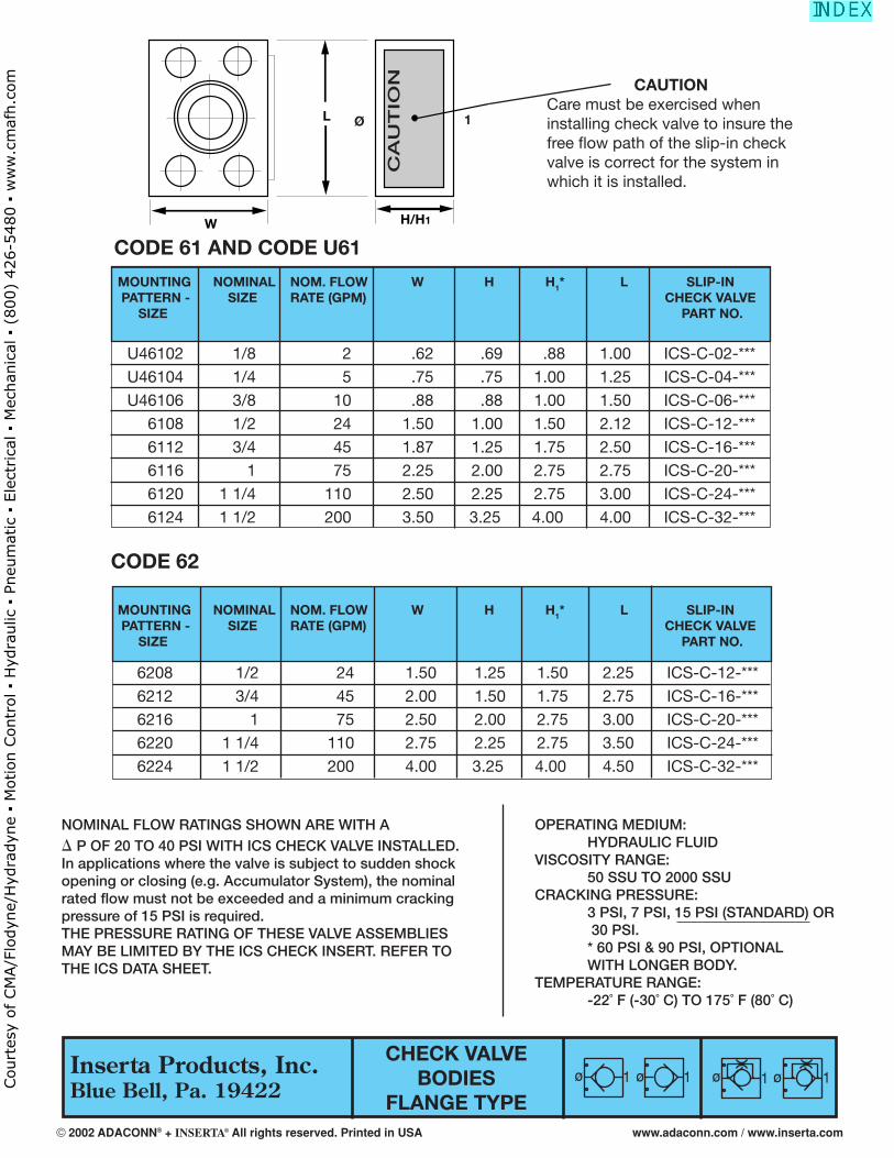
CAUTIONCare must be exercised when installing check valve to insure the free fl ow path of the slip-in check valve is correct for the system in which it is installed.
OPERATING MEDIUM: HYDRAULIC FLUIDVISCOSITY RANGE: 50 SSU TO 2000 SSUCRACKING PRESSURE: 3 PSI, 7 PSI, 15 PSI (STANDARD) OR 30 PSI. * 60 PSI & 90 PSI, OPTIONAL WITH LONGER BODY.TEMPERATURE RANGE: -22˚ F (-30˚ C) TO 175˚ F (80˚ C)
NOMINAL FLOW RATINGS SHOWN ARE WITH A � P OF 20 TO 40 PSI WITH ICS CHECK VALVE INSTALLED.In applications where the valve is subject to sudden shock opening or closing (e.g. Accumulator System), the nominal rated fl ow must not be exceeded and a minimum cracking pressure of 15 PSI is required.THE PRESSURE RATING OF THESE VALVE ASSEMBLIESMAY BE LIMITED BY THE ICS CHECK INSERT. REFER TOTHE ICS DATA SHEET.
CODE 61 AND CODE U61
CODE 62
MOUNTING NOMINAL NOM. FLOW W H H1* L SLIP-IN PATTERN - SIZE RATE (GPM) CHECK VALVE SIZE PART NO.
6208 1/2 24 1.50 1.25 1.50 2.25 ICS-C-12-*** 6212 3/4 45 2.00 1.50 1.75 2.75 ICS-C-16-*** 6216 1 75 2.50 2.00 2.75 3.00 ICS-C-20-*** 6220 1 1/4 110 2.75 2.25 2.75 3.50 ICS-C-24-*** 6224 1 1/2 200 4.00 3.25 4.00 4.50 ICS-C-32-***
L
W H/H1
CA
UT
ION
Ø 1
ø ø1 1 ø ø1 1
MOUNTING NOMINAL NOM. FLOW W H H1* L SLIP-IN PATTERN - SIZE RATE (GPM) CHECK VALVE SIZE PART NO.
U46102 1/8 2 .62 .69 .88 1.00 ICS-C-02-*** U46104 1/4 5 .75 .75 1.00 1.25 ICS-C-04-*** U46106 3/8 10 .88 .88 1.00 1.50 ICS-C-06-*** 6108 1/2 24 1.50 1.00 1.50 2.12 ICS-C-12-*** 6112 3/4 45 1.87 1.25 1.75 2.50 ICS-C-16-*** 6116 1 75 2.25 2.00 2.75 2.75 ICS-C-20-*** 6120 1 1/4 110 2.50 2.25 2.75 3.00 ICS-C-24-*** 6124 1 1/2 200 3.50 3.25 4.00 4.00 ICS-C-32-***
© 2002 ADACONN® + INSERTA® All rights reserved. Printed in USA www.adaconn.com / www.inserta.com
Court
esy
of CM
A/F
lodyn
e/H
ydra
dyn
e ▪
Motion C
ontr
ol ▪
Hyd
raulic
▪ P
neu
mat
ic ▪
Ele
ctrica
l ▪
Mec
han
ical
▪ (
800)
426-5
480 ▪
ww
w.c
maf
h.c
om
Inserta Products, Inc.Blue Bell, Pa. 19422
Inserta Products, Inc.
ORDERING INFORMATION
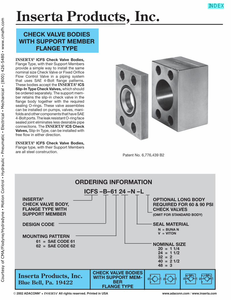
ICFS – B– 61 24 – N – L
CHECK VALVE BODIESWITH SUPPORT MEM-
BERFLANGE TYPE
INSERTA® ICFS Check Valve Bodies, Flange Type, with their Support Members provide a simple way to install the same nominal size Check Valve or Fixed Orifi ce Flow Control Valve in a piping system that uses SAE 4-Bolt fl ange patterns. These bodies accept the INSERTA® ICS Slip-In Type Check Valves, which should be ordered separately. The support mem-ber retains the slip-in check valve in the fl ange body together with the required sealing O-rings. These valve assemblies can be installed on pumps, valves, mani-folds and other components that have SAE 4-Bolt ports. The leak resistant O-ring face sealed joint eliminates less desirable pipe connections. The INSERTA® ICS Check Valves, Slip-In Type, can be installed with free fl ow in either direction.
INSERTA® ICFS Check Valve Bodies, Flange type, with their Support Members are all steel construction.
CHECK VALVE BODIESWITH SUPPORT MEMBER
FLANGE TYPE
INSERTA®
CHECK VALVE BODY,FLANGE TYPE WITHSUPPORT MEMBER
DESIGN CODE
MOUNTING PATTERN 61 = SAE CODE 61 62 = SAE CODE 62 NOMINAL SIZE
20 = 1 1/4 24 = 1 1/2 32 = 2 40 = 2 1/2 48 = 3
OPTIONAL LONG BODYREQUIRED FOR 60 & 90 PSICHECK VALVES (OMIT FOR STANDARD BODY)
SEAL MATERIAL N = BUNA N V = VITON
Patent No. 6,776,439 B2
ø ø1 1 ø ø1 1
© 2002 ADACONN® + INSERTA® All rights reserved. Printed in USA www.adaconn.com / www.inserta.com
Court
esy
of CM
A/F
lodyn
e/H
ydra
dyn
e ▪
Motion C
ontr
ol ▪
Hyd
raulic
▪ P
neu
mat
ic ▪
Ele
ctrica
l ▪
Mec
han
ical
▪ (
800)
426-5
480 ▪
ww
w.c
maf
h.c
om
Inserta Products, Inc.Blue Bell, Pa. 19422
CAUTIONCare must be exercised when installing check valve to insure the free fl ow path of the slip-in check valve is correct for the system in which it is installed.
OPERATING MEDIUM: HYDRAULIC FLUIDVISCOSITY RANGE: 50 SSU TO 2000 SSUCRACKING PRESSURE: 3 PSI, 7 PSI, 15 PSI (STANDARD) OR 30 PSI. * 60 PSI & 90 PSI, OPTIONAL WITH LONGER BODY.TEMPERATURE RANGE: -22˚ F (-30˚ C) TO 175˚ F (80˚ C)
NOMINAL FLOW RATINGS SHOWN ARE WITH A Δ P OF 20 TO 40 PSI WITH ICS CHECK VALVE INSTALLEDIn applications where the valve is subject to sudden shock opening or closing (e.g. Accumulator System), the nominal rated fl ow must not be exceeded and a minimum cracking pressure of 15 PSI is required.THE PRESSURE RATING OF THESE VALVE ASSEMBLIESMAY BE LIMITED BY THE ICS CHECK INSERT. REFER TOTHE ICS DATA SHEET.
SAE CODE 61
CHECK VALVE BODIESWITH SUPPORT MEM-
BERFLANGE TYPE
SAE CODE 62
6120 1 1/4 75 2.25 2.25 3.00 3.00 ICS-C-20-*** 222 6124 1 1/2 110 2.50 2.75 3.25 3.75 ICS-C-24-*** 225 6132 2 200 3.25 3.50 4.25 4.00 ICS-C-32-*** 228 6140 2/1/2 300 3.50 4.25 4.50 4.50 ICS-C-40-*** 232 6148 3 400 4.00 4.25 5.00 5.00 ICS-C-48-*** 237
MOUNTING NOMINAL NOM. FLOW W H H1* L SLIP-IN O-RING PATTERN - SIZE RATE (GPM) CHECK VALVE SIZE NO. SIZE PART NO.
ø ø1 1 ø ø1 1
CA
UT
ION
6220 1 1/4 75 2.50 2.50 3.25 3.50 ICS-C-20-*** 222 6224 1 1/2 110 3.00 2.75 3.25 4.25 ICS-C-24-*** 225 6232 2 200 3.50 3.75 4.50 5.00 ICS-C-32-*** 228 6240 2/1/2 300 4.25 4.25 4.50 6.00 ICS-C-40-*** 232 6248 3 400 5.00 4.25 5.00 8.00 ICS-C-48-*** 237
MOUNTING NOMINAL NOM. FLOW W H H1* L SLIP-IN O-RING PATTERN - SIZE RATE (GPM) CHECK VALVE SIZE NO. SIZE PART NO.
© 2002 ADACONN® + INSERTA® All rights reserved. Printed in USA www.adaconn.com / www.inserta.com
Court
esy
of CM
A/F
lodyn
e/H
ydra
dyn
e ▪
Motion C
ontr
ol ▪
Hyd
raulic
▪ P
neu
mat
ic ▪
Ele
ctrica
l ▪
Mec
han
ical
▪ (
800)
426-5
480 ▪
ww
w.c
maf
h.c
om
Inserta Products, Inc.Blue Bell, Pa. 19422
ORDERING INFORMATION
ICC– A– 12–L
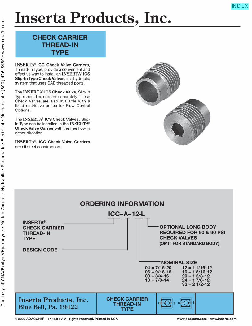
INSERTA® ICC Check Valve Carriers, Thread-in Type, provide a convenient and effective way to install an INSERTA® ICS Slip-In Type Check Valves, in a hydraulic system that uses SAE threaded ports.
The INSERTA® ICS Check Valve, Slip-In Type should be ordered separately. These Check Valves are also available with a fi xed restrictive orifi ce for Flow Control Options.
The INSERTA® ICS Check Valves, Slip-In Type can be installed in the INSERTA® Check Valve Carrier with the free fl ow in either direction.
INSERTA® ICC Check Valve Carriers are all steel construction.
CHECK CARRIERTHREAD-IN
TYPE
INSERTA®
CHECK CARRIERTHREAD-INTYPE
DESIGN CODE
NOMINAL SIZE04 = 7/16-20 12 = 1 1/16-1206 = 9/16-18 16 = 1 5/16-1208 = 3/4-16 20 = 1 5/8-1210 = 7/8-14 24 = 1 7/8-12 32 = 2 1/2-12
CHECK CARRIERTHREAD-IN
TYPEø ø 11
OPTIONAL LONG BODYREQUIRED FOR 60 & 90 PSICHECK VALVES(OMIT FOR STANDARD BODY)
Inserta Products, Inc.
© 2002 ADACONN® + INSERTA® All rights reserved. Printed in USA www.adaconn.com / www.inserta.com
Court
esy
of CM
A/F
lodyn
e/H
ydra
dyn
e ▪
Motion C
ontr
ol ▪
Hyd
raulic
▪ P
neu
mat
ic ▪
Ele
ctrica
l ▪
Mec
han
ical
▪ (
800)
426-5
480 ▪
ww
w.c
maf
h.c
om
Inserta Products, Inc.Blue Bell, Pa. 19422
CHECK CARRIERTHREAD-IN
TYPE
ø ø 11
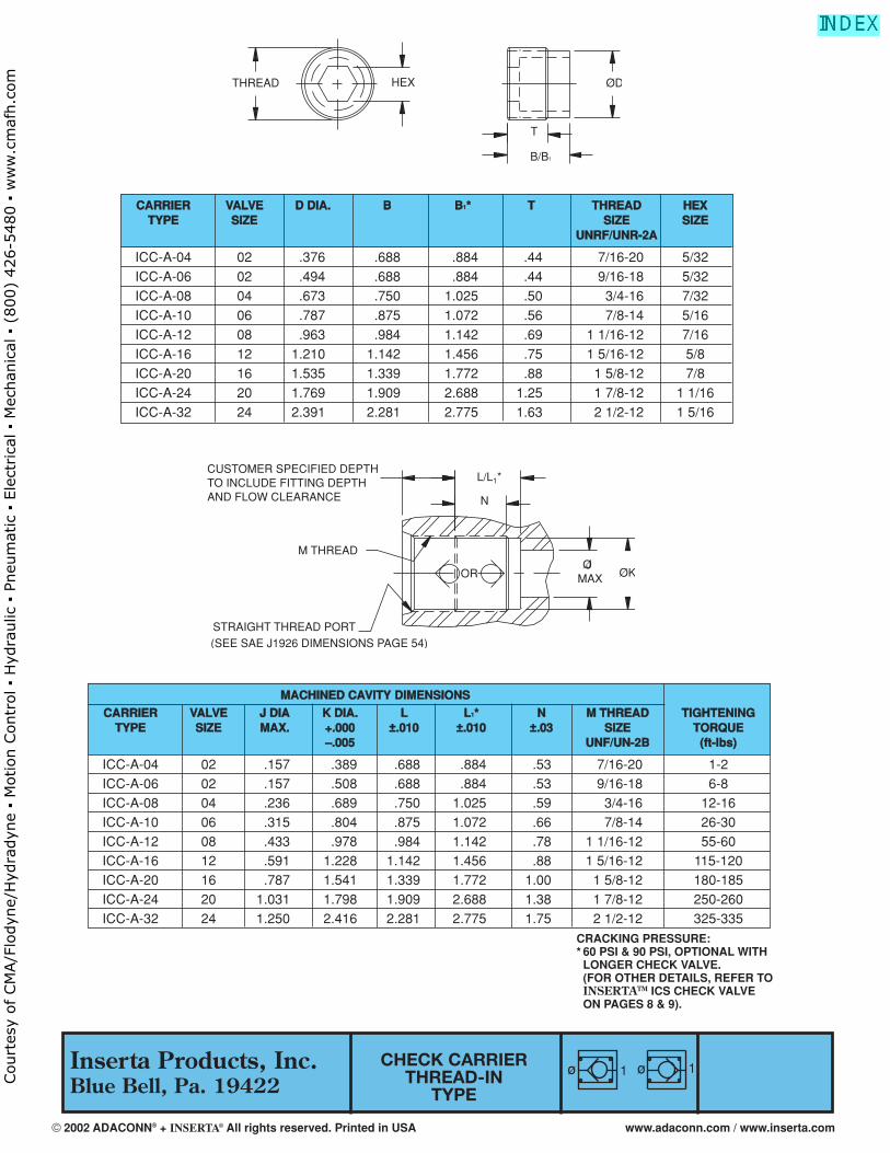
CCAARRRRIIEERR VVAALLVVEE DD DDIIAA.. BB BB11** TT TTHHRREEAADD HHEEXXTTYYPPEE SSIIZZEE SSIIZZEE SSIIZZEE
UUNNRRFF//UUNNRR--22AA
ICC-A-04 02 .376 .688 .884 .44 7/16-20 5/32ICC-A-06 02 .494 .688 .884 .44 9/16-18 5/32ICC-A-08 04 .673 .750 1.025 .50 3/4-16 7/32ICC-A-10 06 .787 .875 1.072 .56 7/8-14 5/16ICC-A-12 08 .963 .984 1.142 .69 1 1/16-12 7/16ICC-A-16 12 1.210 1.142 1.456 .75 1 5/16-12 5/8ICC-A-20 16 1.535 1.339 1.772 .88 1 5/8-12 7/8ICC-A-24 20 1.769 1.909 2.688 1.25 1 7/8-12 1 1/16ICC-A-32 24 2.391 2.281 2.775 1.63 2 1/2-12 1 5/16
MMAACCHHIINNEEDD CCAAVVIITTYY DDIIMMEENNSSIIOONNSS
CCAARRRRIIEERR VVAALLVVEE JJ DDIIAA KK DDIIAA.. LL LL11** NN MM TTHHRREEAADD TTIIGGHHTTEENNIINNGGTTYYPPEE SSIIZZEE MMAAXX.. ++..000000 ±±..001100 ±±..001100 ±±..0033 SSIIZZEE TTOORRQQUUEE
––..000055 UUNNFF//UUNN--22BB ((fftt--llbbss))
ICC-A-04 02 .157 .389 .688 .884 .53 7/16-20 1-2ICC-A-06 02 .157 .508 .688 .884 .53 9/16-18 6-8ICC-A-08 04 .236 .689 .750 1.025 .59 3/4-16 12-16ICC-A-10 06 .315 .804 .875 1.072 .66 7/8-14 26-30ICC-A-12 08 .433 .978 .984 1.142 .78 1 1/16-12 55-60ICC-A-16 12 .591 1.228 1.142 1.456 .88 1 5/16-12 115-120ICC-A-20 16 .787 1.541 1.339 1.772 1.00 1 5/8-12 180-185ICC-A-24 20 1.031 1.798 1.909 2.688 1.38 1 7/8-12 250-260ICC-A-32 24 1.250 2.416 2.281 2.775 1.75 2 1/2-12 325-335
CRACKING PRESSURE:* 60 PSI & 90 PSI, OPTIONAL WITH LONGER CHECK VALVE. (FOR OTHER DETAILS, REFER TO INSERTATM ICS CHECK VALVE ON PAGES 8 & 9).
CUSTOMER SPECIFIED DEPTHTO INCLUDE FITTING DEPTHAND FLOW CLEARANCE
M THREAD
STRAIGHT THREAD PORT(SEE SAE J1926 DIMENSIONS PAGE 54)
N
ØJMAX Ø KOR
L/L1*
THREAD HEX Ø D
T
B/B1
© 2002 ADACONN® + INSERTA® All rights reserved. Printed in USA www.adaconn.com / www.inserta.com
Court
esy
of CM
A/F
lodyn
e/H
ydra
dyn
e ▪
Motion C
ontr
ol ▪
Hyd
raulic
▪ P
neu
mat
ic ▪
Ele
ctrica
l ▪
Mec
han
ical
▪ (
800)
426-5
480 ▪
ww
w.c
maf
h.c
om
CHECK VALVESTHREAD-IN
TYPE
Inserta Products, Inc.Blue Bell, Pa. 19422
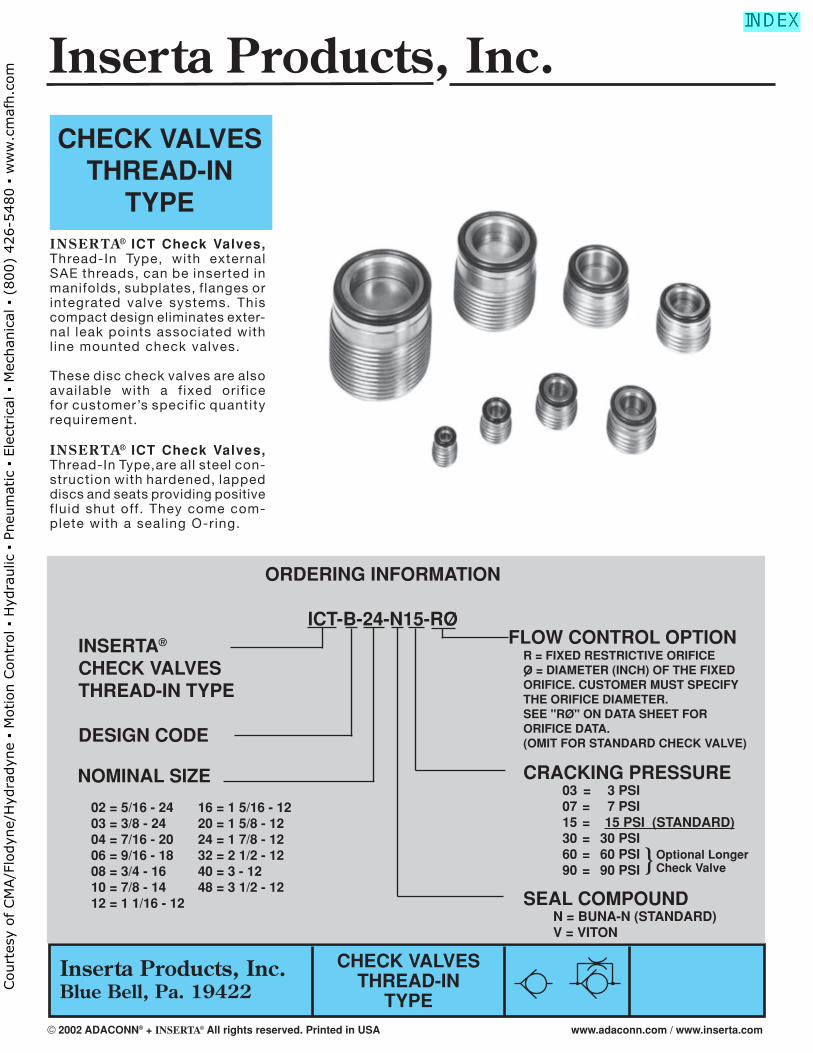
INSER TA® ICT Check Valves, Thread-In Type, with external SAE threads, can be inserted in manifolds, subplates, flanges or integrated valve systems. This compact design eliminates exter-nal leak points associated with l ine mounted check valves.
These disc check valves are also available with a f ixed orif ice for customer’s specif ic quantity requirement.
INSER TA® ICT Check Valves, Thread-In Type,are all steel con-struction with hardened, lapped discs and seats providing positive f luid shut off. They come com-plete with a sealing O-ring.
CHECK VALVESTHREAD-IN
TYPE
CRACKING PRESSURE 03 = 3 PSI 07 = 7 PSI 15 = 15 PSI (STANDARD) 30 = 30 PSI 60 = 60 PSI 90 = 90 PSI
SEAL COMPOUND N = BUNA-N (STANDARD) V = VITON
NOMINAL SIZE
INSERTA®
CHECK VALVESTHREAD-IN TYPE
DESIGN CODE
ORDERING INFORMATION
ICT-B-24-N15-RO
}Optional LongerCheck Valve
FLOW CONTROL OPTION R = FIXED RESTRICTIVE ORIFICE O = DIAMETER (INCH) OF THE FIXED ORIFICE. CUSTOMER MUST SPECIFY THE ORIFICE DIAMETER. SEE "RØ" ON DATA SHEET FOR ORIFICE DATA. (OMIT FOR STANDARD CHECK VALVE)
02 = 5/16 - 24 16 = 1 5/16 - 1203 = 3/8 - 24 20 = 1 5/8 - 1204 = 7/16 - 20 24 = 1 7/8 - 1206 = 9/16 - 18 32 = 2 1/2 - 1208 = 3/4 - 16 40 = 3 - 1210 = 7/8 - 14 48 = 3 1/2 - 1212 = 1 1/16 - 12
Inserta Products, Inc.
© 2002 ADACONN® + INSERTA® All rights reserved. Printed in USA www.adaconn.com / www.inserta.com
Court
esy
of CM
A/F
lodyn
e/H
ydra
dyn
e ▪
Motion C
ontr
ol ▪
Hyd
raulic
▪ P
neu
mat
ic ▪
Ele
ctrica
l ▪
Mec
han
ical
▪ (
800)
426-5
480 ▪
ww
w.c
maf
h.c
om

Inserta Products, Inc.Blue Bell, Pa. 19422
CHECK VALVESTHREAD-IN
TYPE
In applications where the valve is subject to sudden shock opening or closing (e.g. Accumulator System) the nominal rated fl ow must not be exceeded and a minimum cracking pressure of 15 PSI is required.
02 .125 .255 .412 – 5/16-24 .291 03 .190 .345 .428 – 3/8-24 .291 04 .188 .389 .435 .630 7/16-20 .275 06 .281 .508 .455 .710 9/16-18 .275 08 .406 .689 .535 .750 3/4-16 .335 10 .500 .804 .630 .770 7/8-14 .415 12 .625 .978 .750 1.045 1 1/16-12 .495 16 .813 1.228 .910 1.340 1 5/16-12 .590 20 1.031 1.541 1.420 2.440 1 5/8-12 1.025 24 1.250 1.798 1.655 3.000 1 7/8-12 1.420 32 1.750 2.416 2.520 – 2 1/2-12 1.750 40 2.062 2.895 2.988 – 3-12 1.875 48 2.500 3.395 3.113 – 3 1/2-12 1.875
NOMINAL FLOW RATES ARE WITH A ΔP OF 30 TO 40 PSI
IMT-C-02 2.00 4.0 IMT-C-03 2.00 4.0 IMT-C-04 2.00 4.0 IMT-C-06 2.50 4.5 IMT-C-08 3.00 5.0 IMT-C-10 3.50 5.5
IMT-D-12 .95 1.38 9/16 Hex IMT-D-16 1.19 1.38 3/4 Hex IMT-E-20 1.55 1.0 1/2 Square IMT-E-24 1.72 1.0 1/2 Square IMT-E-32 2.39 1.5 3/4 Square IMT-E-40 2.90 1.5 3/4 Square IMT-E-48 3.38 1.5 3/4 Square
INSTALLATION TOOL
PART NO. V W* HEX/SQUARE
OPERATING MEDIUM: HYDRAULIC FLUIDVISCOSITY RANGE: 50 SSU TO 2000 SSUCRACKING PRESSURE: 3 PSI, 7 PSI, 15 PSI (STANDARD) OR 30 PSI. *60 PSI & 90 PSI, OPTIONAL WITH LONGER CHECK VALVE.
VALVE J K L L1* M N SIZE -.005
MACHINED CAVITY DIMENSIONS
V V
WeW
IMT-D-HEXIMT-C-****
Design ESQUARE DR.
IMT-E-**
Wd
Design D*FOR C, D, & E DESIGNS.
MOUNTING POSITION: OPTIONALMAXIMUM OPERATING PRESSURE: 5000 PSI (Contact the Factory for pressures up to 7250 PSI)TEMPERATURE RANGE: –22°F (–30°C) To 175°F (80°C)
NOTE: MINIMUM ORFICE = .016 DIAMETER
NOMINAL INSTALLA- SEATING VALVE FLOW RO O-RING SIZE TION TORQUE
SIZE (GPM) A B B1 C F G H MAX T NO. (mm) TOOL LB-FT
02 1.0 5/16-24 .412 — .245 4 .06 .175 .024 .270 (4.5x1) IMT-C-02 .5–1 . 03 1.8 3/8-24 .428 — .333 4 .07 .224 .039 .270 (6.2X1) IMT-C-03 .5–1 . 04 3.0 7/16-20 .435 .630 .376 4 .10 .228 .039 .255 010 IMT-C-04 1–2 06 6.0 9/16-18 .455 .710 .494 6 .12 .328 .078 .255 012 IMT-C-06 1–2 08 12 3/4-16 .535 .750 .673 8 .15 .453 .078 .285 (13x2) IMT-C-08 2–3 10 17 7/8-14 .630 .770 .787 8 .17 .565 .078 .350 (16x2) IMT-C-10 7–8 12 25 1 1/16-12 .750 1.045 .963 8 .22 .693 .140 .430 116 IMT-D-12 16–17 16 35 1 5/16-12 .910 1.340 1.210 9 .28 .875 .218 .510 213 IMT-D-16 27–29 20 63 1 5/8-12 1.420 2.440 1.535 10 .31 1.161 .315 .940 219 IMT-E-20 45–50 24 80 1 7/8-12 1.655 3.000 1.769 10 .37 1.340 .394 1.055 222 IMT-E-24 80–90 32 135 2 1/2-12 2.520 — 2.391 10 .50 1.804 .394 1.531 227 IMT-E-32 090–100 40 155 3-12 2.988 — 2.883 10 .59 2.187 .394 1.750 231 IMT-E-40 300–340 48 175 3 1/2-12 3.113 — 3.385 10 .69 2.562 .394 1.750 235 IMT-E-48 400–430
*
VALVE DIMENSIONS
© 2002 ADACONN® + INSERTA® All rights reserved. Printed in USA www.adaconn.com / www.inserta.com
Court
esy
of CM
A/F
lodyn
e/H
ydra
dyn
e ▪
Motion C
ontr
ol ▪
Hyd
raulic
▪ P
neu
mat
ic ▪
Ele
ctrica
l ▪
Mec
han
ical
▪ (
800)
426-5
480 ▪
ww
w.c
maf
h.c
om
Inserta Products, Inc.Blue Bell, Pa. 19422
ORDERING INFORMATION
ICFT – A – 61 32 (24) – N 15 – RØINSERTA®
CHECK VALVEFLANGE TYPE(w/ICT CHECK)
SEAL COMPOUND N = BUNA–N (STANDARD) V = VITON
(USED WHEN ICT CHECK SIZE ISSMALLER THAN THENOMINAL SIZE) OMIT WHEN THE SAME
DESIGN CODE
MOUNTING PATTERN 61 = SAE CODE 61 62 = SAE CODE 62
CRACKING PRESSURE 03 = 3 PSI 07 = 7 PSI 15 = 15 PSI (STANDARD) 30 = 30 PSINOMINAL SIZE
08 = 1/2 24 = 1-1/2 12 = 3/4 32 = 2 16 = 1 40 = 2 1/2 20 = 1 1/4 48 = 3
CHECK VALVE4-BOLT
FLANGE TYPE
CHECK VALVES4-BOLT
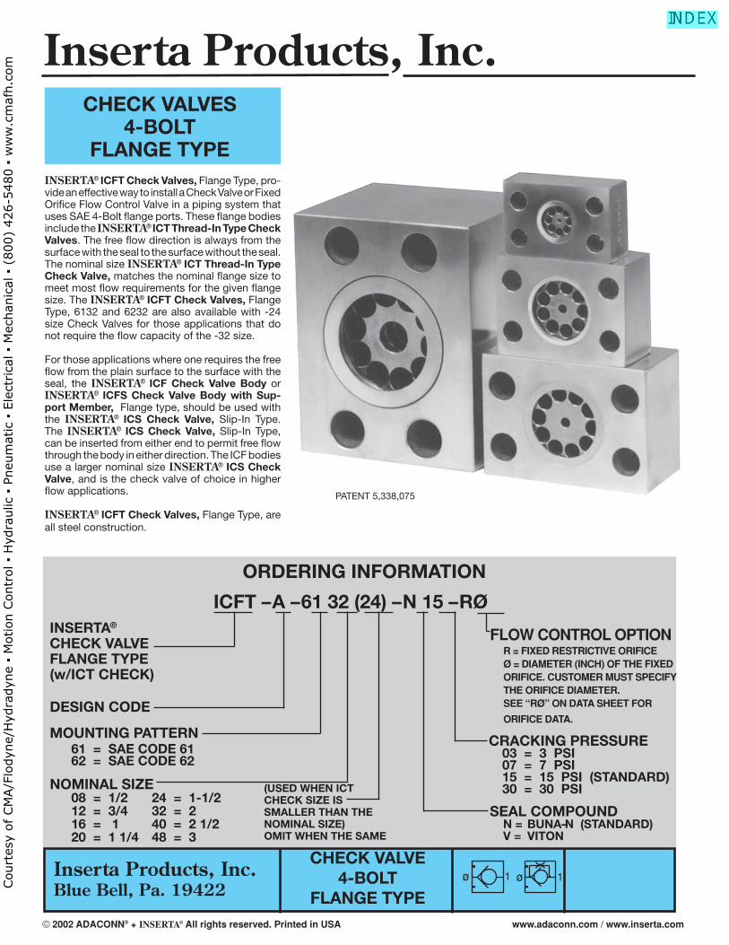
FLANGE TYPEINSERTA® ICFT Check Valves, Flange Type, pro-vide an effective way to install a Check Valve or Fixed Orifi ce Flow Control Valve in a piping system that uses SAE 4-Bolt fl ange ports. These fl ange bodies include the INSERTA® ICT Thread-In Type Check Valves. The free fl ow direction is always from the surface with the seal to the surface without the seal. The nominal size INSERTA® ICT Thread-In Type Check Valve, matches the nominal fl ange size to meet most fl ow requirements for the given fl ange size. The INSERTA® ICFT Check Valves, Flange Type, 6132 and 6232 are also available with -24 size Check Valves for those applications that do not require the fl ow capacity of the -32 size.
For those applications where one requires the free fl ow from the plain surface to the surface with the seal, the INSERTA® ICF Check Valve Body or INSERTA® ICFS Check Valve Body with Sup-port Member, Flange type, should be used with the INSERTA® ICS Check Valve, Slip-In Type. The INSERTA® ICS Check Valve, Slip-In Type, can be inserted from either end to permit free fl ow through the body in either direction. The ICF bodies use a larger nominal size INSERTA® ICS Check Valve, and is the check valve of choice in higher fl ow applications.
INSERTA® ICFT Check Valves, Flange Type, are all steel construction.
PATENT 5,338,075
FLOW CONTROL OPTION R = FIXED RESTRICTIVE ORIFICE Ø = DIAMETER (INCH) OF THE FIXED ORIFICE. CUSTOMER MUST SPECIFY THE ORIFICE DIAMETER. SEE “RØ” ON DATA SHEET FOR
ORIFICE DATA.
ø 1 ø 1
Inserta Products, Inc.
© 2002 ADACONN® + INSERTA® All rights reserved. Printed in USA www.adaconn.com / www.inserta.com
Court
esy
of CM
A/F
lodyn
e/H
ydra
dyn
e ▪
Motion C
ontr
ol ▪
Hyd
raulic
▪ P
neu
mat
ic ▪
Ele
ctrica
l ▪
Mec
han
ical
▪ (
800)
426-5
480 ▪
ww
w.c
maf
h.c
om
Inserta Products, Inc.Blue Bell, Pa. 19422
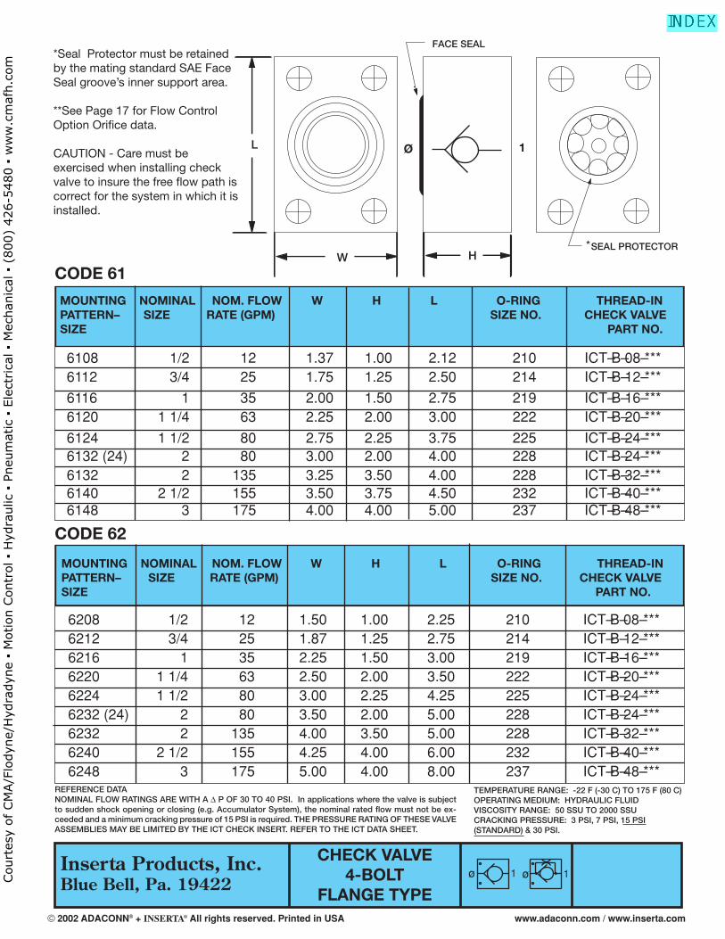
CODE 61
CHECK VALVE4-BOLT
FLANGE TYPE
REFERENCE DATANOMINAL FLOW RATINGS ARE WITH A Δ P OF 30 TO 40 PSI. In applications where the valve is subject to sudden shock opening or closing (e.g. Accumulator System), the nominal rated fl ow must not be ex-ceeded and a minimum cracking pressure of 15 PSI is required. THE PRESSURE RATING OF THESE VALVE ASSEMBLIES MAY BE LIMITED BY THE ICT CHECK INSERT. REFER TO THE ICT DATA SHEET.
MOUNTING NOMINAL NOM. FLOW W H L O-RING THREAD-IN PATTERN– SIZE RATE (GPM) SIZE NO. CHECK VALVE SIZE PART NO.
6108 1/2 12 1.37 1.00 2.12 210 ICT–B–08–*** 6112 3/4 25 1.75 1.25 2.50 214 ICT–B–12–***
6116 1 35 2.00 1.50 2.75 219 ICT–B–16–*** 6120 1 1/4 63 2.25 2.00 3.00 222 ICT–B–20–***
6124 1 1/2 80 2.75 2.25 3.75 225 ICT–B–24–*** 6132 (24) 2 80 3.00 2.00 4.00 228 ICT–B–24–*** 6132 2 135 3.25 3.50 4.00 228 ICT–B–32–*** 6140 2 1/2 155 3.50 3.75 4.50 232 ICT–B–40–*** 6148 3 175 4.00 4.00 5.00 237 ICT–B–48–***
*Seal Protector must be retained by the mating standard SAE Face Seal groove’s inner support area.
**See Page 17 for Flow Control Option Orifi ce data.
CAUTION - Care must be exercised when installing check valve to insure the free fl ow path is correct for the system in which it is installed.
TEMPERATURE RANGE: -22 F (-30 C) TO 175 F (80 C)OPERATING MEDIUM: HYDRAULIC FLUIDVISCOSITY RANGE: 50 SSU TO 2000 SSUCRACKING PRESSURE: 3 PSI, 7 PSI, 15 PSI (STANDARD) & 30 PSI.
MOUNTING NOMINAL NOM. FLOW W H L O-RING THREAD-IN PATTERN– SIZE RATE (GPM) SIZE NO. CHECK VALVE SIZE PART NO.
CODE 62
6208 1/2 12 1.50 1.00 2.25 210 ICT–B–08–*** 6212 3/4 25 1.87 1.25 2.75 214 ICT–B–12–*** 6216 1 35 2.25 1.50 3.00 219 ICT–B–16–*** 6220 1 1/4 63 2.50 2.00 3.50 222 ICT–B–20–*** 6224 1 1/2 80 3.00 2.25 4.25 225 ICT–B–24–*** 6232 (24) 2 80 3.50 2.00 5.00 228 ICT–B–24–*** 6232 2 135 4.00 3.50 5.00 228 ICT–B–32–*** 6240 2 1/2 155 4.25 4.00 6.00 232 ICT–B–40–*** 6248 3 175 5.00 4.00 8.00 237 ICT–B–48–***
ø 1 ø 1
SEAL PROTECTOR
FACE SEAL
W H
L 1Ø
*
© 2002 ADACONN® + INSERTA® All rights reserved. Printed in USA www.adaconn.com / www.inserta.com
Court
esy
of CM
A/F
lodyn
e/H
ydra
dyn
e ▪
Motion C
ontr
ol ▪
Hyd
raulic
▪ P
neu
mat
ic ▪
Ele
ctrica
l ▪
Mec
han
ical
▪ (
800)
426-5
480 ▪
ww
w.c
maf
h.c
om
Inserta Products, Inc.
Viewing INSERTA® Modular Connectors 4-Bolt, Flange type
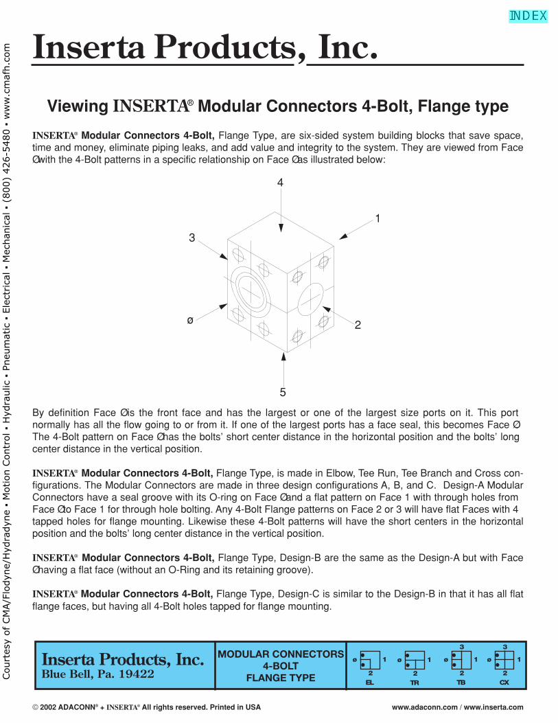
INSERTA® Modular Connectors 4-Bolt, Flange Type, are six-sided system building blocks that save space,time and money, eliminate piping leaks, and add value and integrity to the system. They are viewed from FaceØ with the 4-Bolt patterns in a specific relationship on Face Ø as illustrated below:
By definition Face Ø is the front face and has the largest or one of the largest size ports on it. This port normally has all the flow going to or from it. If one of the largest ports has a face seal, this becomes Face Ø.The 4-Bolt pattern on Face Ø has the bolts’ short center distance in the horizontal position and the bolts’ longcenter distance in the vertical position.
INSERTA® Modular Connectors 4-Bolt, Flange Type, is made in Elbow, Tee Run, Tee Branch and Cross con-figurations. The Modular Connectors are made in three design configurations A, B, and C. Design-A ModularConnectors have a seal groove with its O-ring on Face Ø and a flat pattern on Face 1 with through holes fromFace Ø to Face 1 for through hole bolting. Any 4-Bolt Flange patterns on Face 2 or 3 will have flat Faces with 4tapped holes for flange mounting. Likewise these 4-Bolt patterns will have the short centers in the horizontalposition and the bolts’ long center distance in the vertical position.
INSERTA® Modular Connectors 4-Bolt, Flange Type, Design-B are the same as the Design-A but with FaceØ having a flat face (without an O-Ring and its retaining groove).
INSERTA® Modular Connectors 4-Bolt, Flange Type, Design-C is similar to the Design-B in that it has all flatflange faces, but having all 4-Bolt holes tapped for flange mounting.
Inserta Products, Inc.Blue Bell, Pa. 19422
MODULAR CONNECTORS4-BOLT
FLANGE TYPE CX
ø
3
1
2EL
ø 1
2TR
ø 1
2TB
ø
3
1
2
4
3
1
ø 2
5
© 2002 ADACONN® + INSERTA® All rights reserved. Printed in USA www.adaconn.com / www.inserta.com
Court
esy
of CM
A/F
lodyn
e/H
ydra
dyn
e ▪
Motion C
ontr
ol ▪
Hyd
raulic
▪ P
neu
mat
ic ▪
Ele
ctrica
l ▪
Mec
han
ical
▪ (
800)
426-5
480 ▪
ww
w.c
maf
h.c
om
21
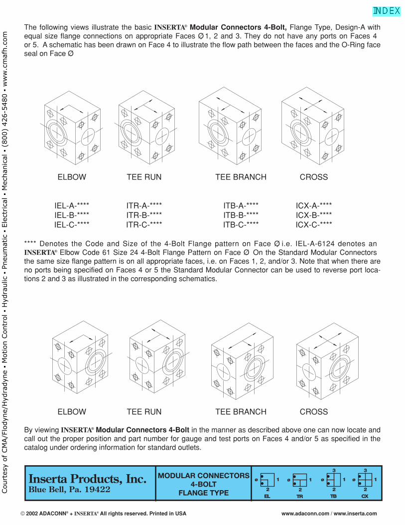
The following views illustrate the basic INSERTA® Modular Connectors 4-Bolt, Flange Type, Design-A withequal size flange connections on appropriate Faces Ø, 1, 2 and 3. They do not have any ports on Faces 4or 5. A schematic has been drawn on Face 4 to illustrate the flow path between the faces and the O-Ring faceseal on Face Ø.
ELBOW TEE RUN TEE BRANCH CROSS
IEL-A-**** ITR-A-**** ITB-A-**** ICX-A-****IEL-B-**** ITR-B-**** ITB-B-**** ICX-B-****IEL-C-**** ITR-C-**** ITB-C-**** ICX-C-****
**** Denotes the Code and Size of the 4-Bolt Flange pattern on Face Ø, i.e. IEL-A-6124 denotes anINSERTA® Elbow Code 61 Size 24 4-Bolt Flange Pattern on Face Ø. On the Standard Modular Connectorsthe same size flange pattern is on all appropriate faces, i.e. on Faces 1, 2, and/or 3. Note that when there areno ports being specified on Faces 4 or 5 the Standard Modular Connector can be used to reverse port loca-tions 2 and 3 as illustrated in the corresponding schematics.
ELBOW TEE RUN TEE BRANCH CROSS
By viewing INSERTA® Modular Connectors 4-Bolt in the manner as described above one can now locate andcall out the proper position and part number for gauge and test ports on Faces 4 and/or 5 as specified in thecatalog under ordering information for standard outlets.
MODULAR CONNECTORS4-BOLT
FLANGE TYPE CX
ø
3
1
2EL
ø 1
2TR
ø 1
2TB
ø
3
1
2
Inserta Products, Inc.Blue Bell, Pa. 19422
© 2002 ADACONN® + INSERTA® All rights reserved. Printed in USA www.adaconn.com / www.inserta.com
Court
esy
of CM
A/F
lodyn
e/H
ydra
dyn
e ▪
Motion C
ontr
ol ▪
Hyd
raulic
▪ P
neu
mat
ic ▪
Ele
ctrica
l ▪
Mec
han
ical
▪ (
800)
426-5
480 ▪
ww
w.c
maf
h.c
om
Blue Bell, Pa. 19422
4 & 2-BOLTFLANGE PORTS &
FLANGE ADAPTERS
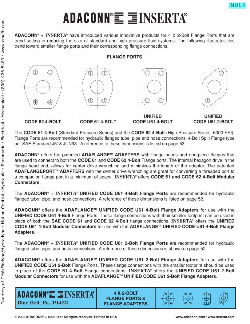
ADACONN® + INSERTA® have introduced various innovative products for 4 & 2-Bolt Flange Ports that aretrend setting in reducing the size of standard and high pressure fluid systems. The following illustrates thistrend toward smaller flange ports and their corresponding flange connections.
FLANGE PORTS
UNIFIED UNIFIEDCODE 62 4-BOLT CODE 61 4-BOLT CODE U61 4-BOLT CODE U61 2-BOLT
The CODE 61 4-Bolt (Standard Pressure Series) and the CODE 62 4-Bolt (High Pressure Series –6000 PSI)Flange Ports are recommended for hydraulic flanged tube, pipe and hose connections, 4-Bolt Split Flange typeper SAE Standard J518 JUN93. A reference to these dimensions is listed on page 53.
ADACONN® offers the patented ADAFLANGETM ADAPTERS with flange heads and one-piece flanges thatare used to connect to both the CODE 61 and CODE 62 4-Bolt Flange ports. The internal hexagon drive in theflange head end, allows for center drive wrenching and minimizes the length of the adapter. The patentedADAFLANGEPORTTM ADAPTERS with the center drive wrenching are great for converting a threaded port toa companion flange port in a minimum of space. INSERTA® offers CODE 61 and CODE 62 4-Bolt ModularConnectors.
The ADACONN® + INSERTA® UNIFIED CODE U61 4-Bolt Flange Ports are recommended for hydraulicflanged tube, pipe, and hose connections. A reference of these dimensions is listed on page 52.
ADACONN® offers the ADAFLANGETM UNIFIED CODE U61 4-Bolt Flange Adapters for use with the UNIFIED CODE U61 4-Bolt Flange Ports. These flange connections with their smaller footprint can be used inplace of both the SAE CODE 61 and CODE 62 4-Bolt flange connections. INSERTA® offers the UNIFIEDCODE U61 4-Bolt Modular Connectors for use with the ADAFLANGETM UNIFIED CODE U61 4-Bolt FlangeAdapters.
The ADACONN® + INSERTA® UNIFIED CODE U61 2-Bolt Flange Ports are recommended for hydraulicflanged tube, pipe, and hose connections. A reference of these dimensions is shown on page 52.
ADACONN® offers the ADAFLANGETM UNIFIED CODE U61 2-Bolt Flange Adapters for use with theUNIFIED CODE U61 2-Bolt Flange Ports. These flange connections with the smaller footprint should be usedin place of the CODE 61 4-Bolt Flange connections. INSERTA® offers the UNIFIED CODE U61 2-BoltModular Connectors for use with the ADAFLANGETM UNIFIED CODE U61 2-Bolt Flange Adapters.
® ®
® ®
© 2002 ADACONN® + INSERTA® All rights reserved. Printed in USA www.adaconn.com / www.inserta.com
Court
esy
of CM
A/F
lodyn
e/H
ydra
dyn
e ▪
Motion C
ontr
ol ▪
Hyd
raulic
▪ P
neu
mat
ic ▪
Ele
ctrica
l ▪
Mec
han
ical
▪ (
800)
426-5
480 ▪
ww
w.c
maf
h.c
om
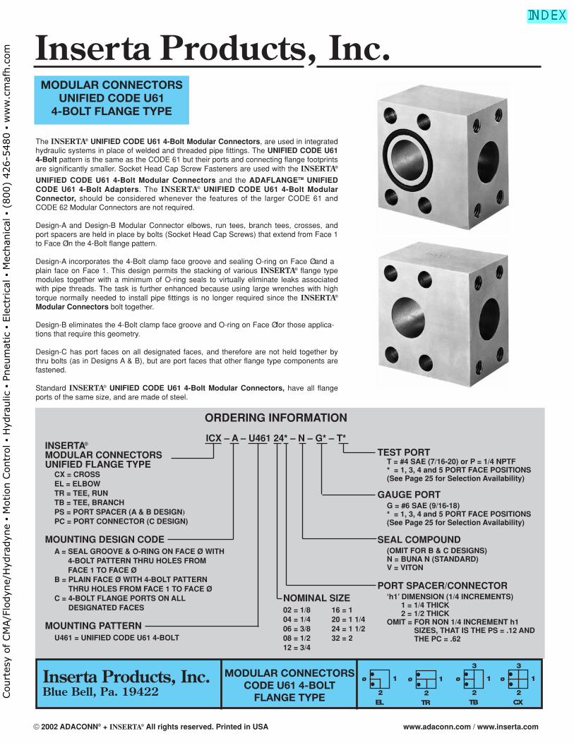
The INSERTA® UNIFIED CODE U61 4-Bolt Modular Connectors, are used in integratedhydraulic systems in place of welded and threaded pipe fittings. The UNIFIED CODE U614-Bolt pattern is the same as the CODE 61 but their ports and connecting flange footprintsare significantly smaller. Socket Head Cap Screw Fasteners are used with the INSERTA®
UNIFIED CODE U61 4-Bolt Modular Connectors and the ADAFLANGETM UNIFIEDCODE U61 4-Bolt Adapters. The INSERTA® UNIFIED CODE U61 4-Bolt ModularConnector, should be considered whenever the features of the larger CODE 61 andCODE 62 Modular Connectors are not required.
Design-A and Design-B Modular Connector elbows, run tees, branch tees, crosses, andport spacers are held in place by bolts (Socket Head Cap Screws) that extend from Face 1to Face Ø in the 4-Bolt flange pattern.
Design-A incorporates the 4-Bolt clamp face groove and sealing O-ring on Face Ø and aplain face on Face 1. This design permits the stacking of various INSERTA® flange typemodules together with a minimum of O-ring seals to virtually eliminate leaks associatedwith pipe threads. The task is further enhanced because using large wrenches with hightorque normally needed to install pipe fittings is no longer required since the INSERTA®
Modular Connectors bolt together.
Design-B eliminates the 4-Bolt clamp face groove and O-ring on Face Ø for those applica-tions that require this geometry.
Design-C has port faces on all designated faces, and therefore are not held together bythru bolts (as in Designs A & B), but are port faces that other flange type components arefastened.
Standard INSERTA® UNIFIED CODE U61 4-Bolt Modular Connectors, have all flangeports of the same size, and are made of steel.
ORDERING INFORMATION
ICX – A – U461 24* – N – G* – T*INSERTA®
MODULAR CONNECTORSUNIFIED FLANGE TYPE
CX = CROSSEL = ELBOWTR = TEE, RUNTB = TEE, BRANCHPS = PORT SPACER (A & B DESIGN)PC = PORT CONNECTOR (C DESIGN)
MOUNTING DESIGN CODEA = SEAL GROOVE & O-RING ON FACE Ø WITH
4-BOLT PATTERN THRU HOLES FROMFACE 1 TO FACE Ø
B = PLAIN FACE Ø WITH 4-BOLT PATTERNTHRU HOLES FROM FACE 1 TO FACE Ø
C = 4-BOLT FLANGE PORTS ON ALLDESIGNATED FACES
MOUNTING PATTERNU461 = UNIFIED CODE U61 4-BOLT
MODULAR CONNECTORSCODE U61 4-BOLT
FLANGE TYPE
MODULAR CONNECTORSUNIFIED CODE U61
4-BOLT FLANGE TYPE
TEST PORTT = #4 SAE (7/16-20) or P = 1/4 NPTF* = 1, 3, 4 and 5 PORT FACE POSITIONS(See Page 25 for Selection Availability)
GAUGE PORTG = #6 SAE (9/16-18)* = 1, 3, 4 and 5 PORT FACE POSITIONS(See Page 25 for Selection Availability)
SEAL COMPOUND(OMIT FOR B & C DESIGNS)N = BUNA N (STANDARD)V = VITON
PORT SPACER/CONNECTOR‘h1’ DIMENSION (1/4 INCREMENTS)
1 = 1/4 THICK2 = 1/2 THICK
OMIT = FOR NON 1/4 INCREMENT h1SIZES, THAT IS THE PS = .12 ANDTHE PC = .62
NOMINAL SIZE02 = 1/8 16 = 104 = 1/4 20 = 1 1/406 = 3/8 24 = 1 1/208 = 1/2 32 = 212 = 3/4
CX
ø
3
1
2EL
ø 1
2TR
ø 1
2TB
ø
3
1
2
Inserta Products, Inc.Blue Bell, Pa. 19422
Inserta Products, Inc.
© 2002 ADACONN® + INSERTA® All rights reserved. Printed in USA www.adaconn.com / www.inserta.com
Court
esy
of CM
A/F
lodyn
e/H
ydra
dyn
e ▪
Motion C
ontr
ol ▪
Hyd
raulic
▪ P
neu
mat
ic ▪
Ele
ctrica
l ▪
Mec
han
ical
▪ (
800)
426-5
480 ▪
ww
w.c
maf
h.c
om
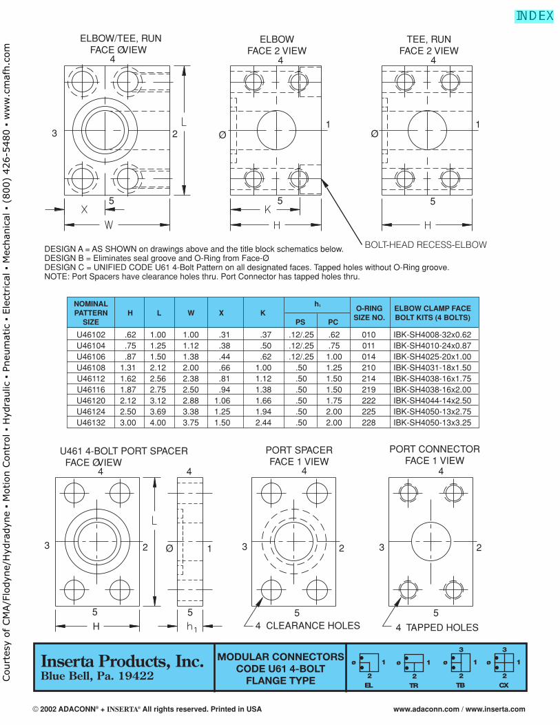
MODULAR CONNECTORSCODE U61 4-BOLT
FLANGE TYPE
ELBOW/TEE, RUNFACE Ø VIEW
ELBOWFACE 2 VIEW
TEE, RUNFACE 2 VIEW
44 4
3 2
5 5
1Ø Ø
1
5
U461 4-BOLT PORT SPACER FACE Ø VIEW
PORT SPACERFACE 1 VIEW
PORT CONNECTORFACE 1 VIEW
4 CLEARANCE HOLES 4 TAPPED HOLES
4 4 4
3 2 Ø 1 3 2 3 2
55 5H
4
5
DESIGN A = AS SHOWN on drawings above and the title block schematics below.DESIGN B = Eliminates seal groove and O-Ring from Face-Ø.DESIGN C = UNIFIED CODE U61 4-Bolt Pattern on all designated faces. Tapped holes without O-Ring groove.NOTE: Port Spacers have clearance holes thru. Port Connector has tapped holes thru.
NOMINAL h1
PATTERN H L W X KO-RING ELBOW CLAMP FACE
SIZE PS PCSIZE NO. BOLT KITS (4 BOLTS)
U46102 .62 1.00 1.00 .31 .37 .12/.25 .62 010 IBK-SH4008-32x0.62U46104 .75 1.25 1.12 .38 .50 .12/.25 .75 011 IBK-SH4010-24x0.87U46106 .87 1.50 1.38 .44 .62 .12/.25 1.00 014 IBK-SH4025-20x1.00U46108 1.31 2.12 2.00 .66 1.00 .50 1.25 210 IBK-SH4031-18x1.50U46112 1.62 2.56 2.38 .81 1.12 .50 1.50 214 IBK-SH4038-16x1.75U46116 1.87 2.75 2.50 .94 1.38 .50 1.50 219 IBK-SH4038-16x2.00U46120 2.12 3.12 2.88 1.06 1.66 .50 1.75 222 IBK-SH4044-14x2.50U46124 2.50 3.69 3.38 1.25 1.94 .50 2.00 225 IBK-SH4050-13x2.75U46132 3.00 4.00 3.75 1.50 2.44 .50 2.00 228 IBK-SH4050-13x3.25
BOLT-HEAD RECESS-ELBOW
CX
ø
3
1
2EL
ø 1
2TR
ø 1
2TB
ø
3
1
2
Inserta Products, Inc.Blue Bell, Pa. 19422
© 2002 ADACONN® + INSERTA® All rights reserved. Printed in USA www.adaconn.com / www.inserta.com
Court
esy
of CM
A/F
lodyn
e/H
ydra
dyn
e ▪
Motion C
ontr
ol ▪
Hyd
raulic
▪ P
neu
mat
ic ▪
Ele
ctrica
l ▪
Mec
han
ical
▪ (
800)
426-5
480 ▪
ww
w.c
maf
h.c
om
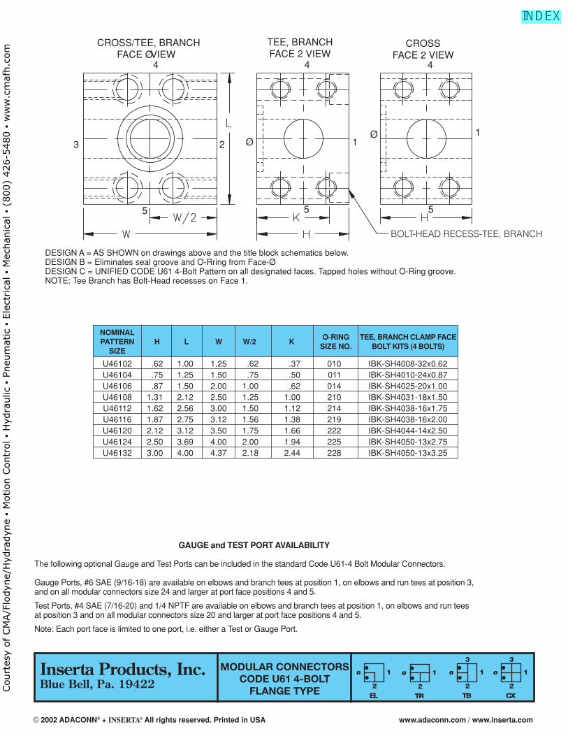
MODULAR CONNECTORSCODE U61 4-BOLT
FLANGE TYPE
CROSS/TEE, BRANCHFACE Ø VIEW
TEE, BRANCHFACE 2 VIEW
CROSSFACE 2 VIEW
3 2 Ø 11Ø
5 5 5
4 4 4
DESIGN A = AS SHOWN on drawings above and the title block schematics below.DESIGN B = Eliminates seal groove and O-Rring from Face-Ø.DESIGN C = UNIFIED CODE U61 4-Bolt Pattern on all designated faces. Tapped holes without O-Ring groove.NOTE: Tee Branch has Bolt-Head recesses on Face 1.
GAUGE and TEST PORT AVAILABILITY
The following optional Gauge and Test Ports can be included in the standard Code U61-4 Bolt Modular Connectors.
Gauge Ports, #6 SAE (9/16-18) are available on elbows and branch tees at position 1, on elbows and run tees at position 3,and on all modular connectors size 24 and larger at port face positions 4 and 5.
Test Ports, #4 SAE (7/16-20) and 1/4 NPTF are available on elbows and branch tees at position 1, on elbows and run teesat position 3 and on all modular connectors size 20 and larger at port face positions 4 and 5.
Note: Each port face is limited to one port, i.e. either a Test or Gauge Port.
NOMINALPATTERN H L W W/2 K
O-RING TEE, BRANCH CLAMP FACE
SIZESIZE NO. BOLT KITS (4 BOLTS)
U46102 .62 1.00 1.25 .62 .37 010 IBK-SH4008-32x0.62U46104 .75 1.25 1.50 .75 .50 011 IBK-SH4010-24x0.87U46106 .87 1.50 2.00 1.00 .62 014 IBK-SH4025-20x1.00U46108 1.31 2.12 2.50 1.25 1.00 210 IBK-SH4031-18x1.50U46112 1.62 2.56 3.00 1.50 1.12 214 IBK-SH4038-16x1.75U46116 1.87 2.75 3.12 1.56 1.38 219 IBK-SH4038-16x2.00U46120 2.12 3.12 3.50 1.75 1.66 222 IBK-SH4044-14x2.50U46124 2.50 3.69 4.00 2.00 1.94 225 IBK-SH4050-13x2.75U46132 3.00 4.00 4.37 2.18 2.44 228 IBK-SH4050-13x3.25
CX
ø
3
1
2EL
ø 1
2TR
ø 1
2TB
ø
3
1
2
BOLT-HEAD RECESS-TEE, BRANCH
Inserta Products, Inc.Blue Bell, Pa. 19422
© 2002 ADACONN® + INSERTA® All rights reserved. Printed in USA www.adaconn.com / www.inserta.com
Court
esy
of CM
A/F
lodyn
e/H
ydra
dyn
e ▪
Motion C
ontr
ol ▪
Hyd
raulic
▪ P
neu
mat
ic ▪
Ele
ctrica
l ▪
Mec
han
ical
▪ (
800)
426-5
480 ▪
ww
w.c
maf
h.c
om
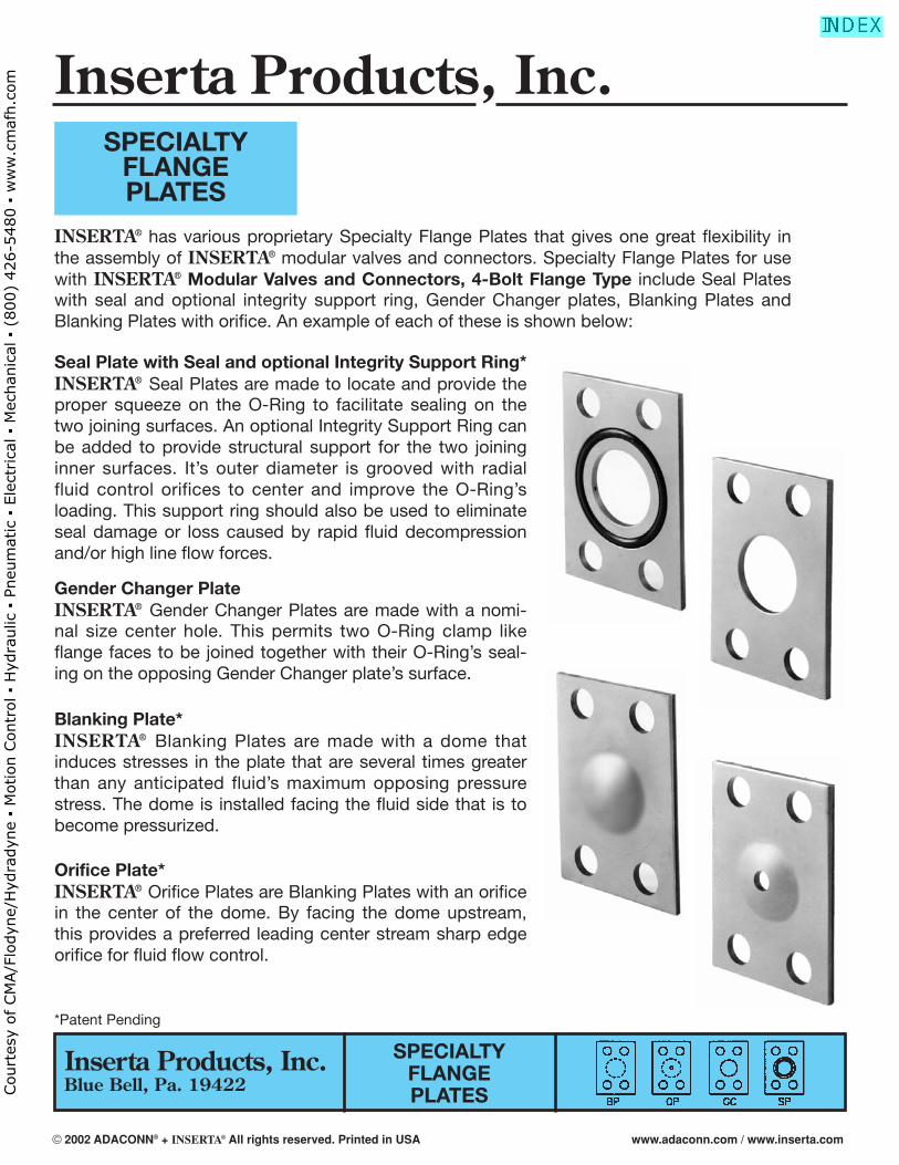
SPECIALTYFLANGEPLATES
INSERTA® has various proprietary Specialty Flange Plates that gives one great flexibility inthe assembly of INSERTA® modular valves and connectors. Specialty Flange Plates for usewith INSERTA® Modular Valves and Connectors, 4-Bolt Flange Type include Seal Plateswith seal and optional integrity support ring, Gender Changer plates, Blanking Plates andBlanking Plates with orifice. An example of each of these is shown below:
SPECIALTYFLANGEPLATES
Seal Plate with Seal and optional Integrity Support Ring*INSERTA® Seal Plates are made to locate and provide theproper squeeze on the O-Ring to facilitate sealing on thetwo joining surfaces. An optional Integrity Support Ring canbe added to provide structural support for the two joininginner surfaces. It’s outer diameter is grooved with radialfluid control orifices to center and improve the O-Ring’sloading. This support ring should also be used to eliminateseal damage or loss caused by rapid fluid decompressionand/or high line flow forces.
Gender Changer PlateINSERTA® Gender Changer Plates are made with a nomi-nal size center hole. This permits two O-Ring clamp likeflange faces to be joined together with their O-Ring’s seal-ing on the opposing Gender Changer plate’s surface.
Blanking Plate*INSERTA® Blanking Plates are made with a dome thatinduces stresses in the plate that are several times greaterthan any anticipated fluid’s maximum opposing pressurestress. The dome is installed facing the fluid side that is tobecome pressurized.
Orifice Plate*INSERTA® Orifice Plates are Blanking Plates with an orificein the center of the dome. By facing the dome upstream,this provides a preferred leading center stream sharp edgeorifice for fluid flow control.
*Patent Pending
Inserta Products, Inc.Blue Bell, Pa. 19422
Inserta Products, Inc.
© 2002 ADACONN® + INSERTA® All rights reserved. Printed in USA www.adaconn.com / www.inserta.com
Court
esy
of CM
A/F
lodyn
e/H
ydra
dyn
e ▪
Motion C
ontr
ol ▪
Hyd
raulic
▪ P
neu
mat
ic ▪
Ele
ctrica
l ▪
Mec
han
ical
▪ (
800)
426-5
480 ▪
ww
w.c
maf
h.c
om
U46102 1/8 1.00 .62 .05 010 6208 1/2 2.25 1.50 210U46104 1/4 1.25 .75 .05 011 6212 3/4 2.75 1.88 214U46106 3/8 1.50 .88 .05 014 6216 1 3.00 2.25 .11 219
6108 1/2 2.12 1.38 210 6220 1 1/4 3.25 2.50 2226112 3/4 2.50 1.75 214 6224 1 1/2 4.25 3.00 2256116 1 2.75 2.00 .11 219 6232(1) 2 5.00 4.00 .24 2286120 1 1/4 3.00 2.25 222 6240(2) 2 1/2 6.75 4.25 .11 N/A 2326124 1 1/2 3.75 2.75 225 6248(2) 3 8.50 5.25 .11 N/A 2376132(1) 2 4.00 3.25 .24 2286140(2) 2 1/2 4.50 3.50 .11 N/A 2326148(2) 3 5.25 4.25 .11 N/A 237
L
W
ø d ORIFICE
BLANKINGPLATE
O-RING SEAL PLATE
ø A ø A
t.13
ORDERING INFORMATIONISP — A — 61 12 — S — N — IS
INSERTA®
SPECIALTY FLANGE PLATES
DESIGN CODE
BP = BLANKING PLATEOP = ORIFICE PLATEGC = GENDER CHANGERSP = SEAL PLATE OPTIONS
IS = INTEGRITY SUPPORT RINGO*** = ORIFICE SIZE
FIRST DIGIT - INCHES2 & 3 DIGIT ADDS DECIMALINCREMENTS, I.E. 0.25
SEAL MATERIALN = BUNA NV = VITON
SEAL PLATE MATERIALS = STEEL
NOMINAL SIZE02 = 1/8 08 = 1/2 20 = 1 1/4 40 = 2 1/204 = 1/4 12 = 3/4 24 = 1 1/2 48 = 306 = 3/8 16 = 1 32 = 2
MOUNTING PATTERNU461 = UNIFIED CODE U61 4-BOLT
61 = SAE CODE 6162 = SAE CODE 62
ADIA. L W tPATTERN
SIZE
SPECIALTYFLANGEPLATES
d*DIA.
O-RINGSIZE NO.
CU
ST
OM
ER
SP
EC
IFIE
D
ADIA. L W tPATTERN
SIZEd*
DIA.O-RING
SIZE NO.
(1) t = .11 for seal plate and gender changer.(2) Sizes 6*40 & 6*48 are not available in blanking or orifice plates.
CU
ST
OM
ER
SP
EC
IFIE
D
ORIFICEPLATE
GENDERCHANGER
PLATE
O-RINGSEALPLATE
*MIN. Ø = .016
Inserta Products, Inc.Blue Bell, Pa. 19422
© 2002 ADACONN® + INSERTA® All rights reserved. Printed in USA www.adaconn.com / www.inserta.com
Court
esy
of CM
A/F
lodyn
e/H
ydra
dyn
e ▪
Motion C
ontr
ol ▪
Hyd
raulic
▪ P
neu
mat
ic ▪
Ele
ctrica
l ▪
Mec
han
ical
▪ (
800)
426-5
480 ▪
ww
w.c
maf
h.c
om
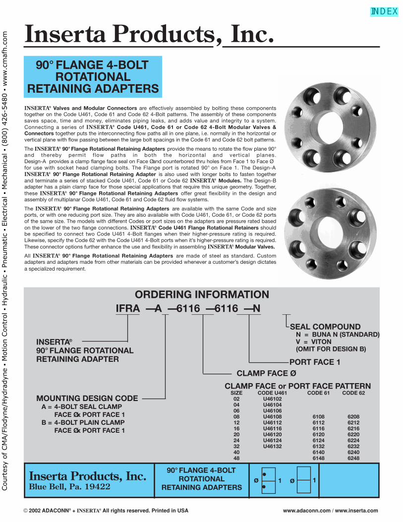
90° FLANGE 4-BOLT ROTATIONAL
RETAINING ADAPTERSINSERTA® Valves and Modular Connectors are effectively assembled by bolting these componentstogether on the Code U461, Code 61 and Code 62 4-Bolt patterns. The assembly of these componentssaves space, time and money, eliminates piping leaks, and adds value and integrity to a system.Connecting a series of INSERTA® Code U461, Code 61 or Code 62 4-Bolt Modular Valves &Connectors together puts the interconnecting flow paths all in one plane, i.e. normally in the horizontal orvertical plane with flow passing between the large bolt spacings in the Code 61 and Code 62 bolt patterns.
The INSERTA® 90° Flange Rotational Retaining Adapters provide the means to rotate the flow plane 90°and thereby permit f low paths in both the horizontal and vertical planes. Design-A provides a clamp flange face seal on Face Ø and counterbored thru holes from Face 1 to Face Øfor use with socket head clamping bolts. The Flange port is rotated 90° on Face 1. The Design-AINSERTA® 90° Flange Rotational Retaining Adapter is also used with longer bolts to fasten togetherand terminate a series of stacked Code U461, Code 61 or Code 62 INSERTA® Modules. The Design-Badapter has a plain clamp face for those special applications that require this unique geometry. Together,these INSERTA® 90° Flange Rotational Retaining Adapters offer great flexibility in the design andassembly of multiplanar Code U461, Code 61 and Code 62 fluid flow systems.
The INSERTA® 90° Flange Rotational Retaining Adapters are available with the same Code and sizeports, or with one reducing port size. They are also available with Code U461, Code 61, or Code 62 portsof the same size. The models with different Codes or port sizes on the adapters are pressure rated basedon the lower of the two flange connections. INSERTA® Code U461 Flange Rotational Retainers shouldbe specified to connect two Code U461 4-Bolt flanges when their higher-pressure rating is required.Likewise, specify the Code 62 with the Code U461 4-Bolt ports when it’s higher-pressure rating is required.These connector options further enhance the use and flexibility in assembling INSERTA® Modular Valves.
All INSERTA® 90° Flange Rotational Retaining Adapters are made of steel as standard. Customadapters and adapters made from other materials can be provided whenever a customer’s design dictatesa specialized requirement.
90° FLANGE 4-BOLTROTATIONAL
RETAINING ADAPTERS
ORDERING INFORMATIONIFRA — A — 6116 — 6116 — N
INSERTA®
90° FLANGE ROTATIONAL RETAINING ADAPTER
MOUNTING DESIGN CODEA = 4-BOLT SEAL CLAMP
FACE Ø x PORT FACE 1B = 4-BOLT PLAIN CLAMP
FACE Ø x PORT FACE 1
PORT FACE 1
SEAL COMPOUNDN = BUNA N (STANDARD)V = VITON(OMIT FOR DESIGN B)
CLAMP FACE Ø
CLAMP FACE or PORT FACE PATTERNSIZE CODE U461 CODE 61 CODE 62
02 U4610204 U4610406 U4610608 U46108 6108 620812 U46112 6112 621216 U46116 6116 621620 U46120 6120 622024 U46124 6124 622432 U46132 6132 623240 6140 624048 6148 6248
••
ø ø1 1Inserta Products, Inc.Blue Bell, Pa. 19422
Inserta Products, Inc.
© 2002 ADACONN® + INSERTA® All rights reserved. Printed in USA www.adaconn.com / www.inserta.com
Court
esy
of CM
A/F
lodyn
e/H
ydra
dyn
e ▪
Motion C
ontr
ol ▪
Hyd
raulic
▪ P
neu
mat
ic ▪
Ele
ctrica
l ▪
Mec
han
ical
▪ (
800)
426-5
480 ▪
ww
w.c
maf
h.c
om
90° FLANGE 4-BOLTROTATIONAL
RETAINING ADAPTERS
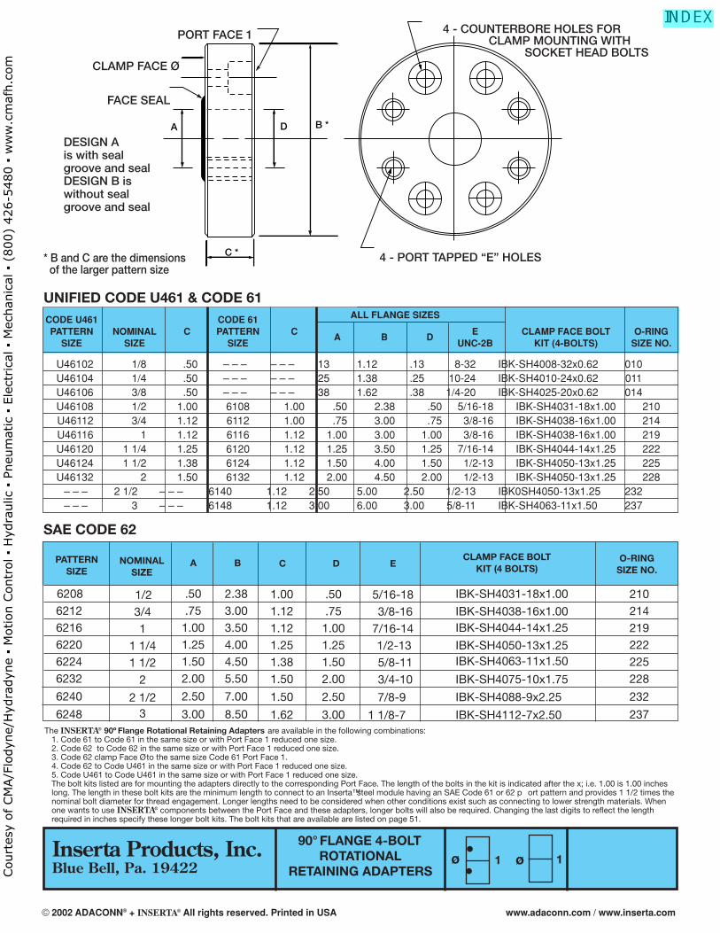
The INSERTA® 90º Flange Rotational Retaining Adapters are available in the following combinations: 1. Code 61 to Code 61 in the same size or with Port Face 1 reduced one size.2. Code 62 to Code 62 in the same size or with Port Face 1 reduced one size.3. Code 62 clamp Face Ø to the same size Code 61 Port Face 1.4. Code 62 to Code U461 in the same size or with Port Face 1 reduced one size.5. Code U461 to Code U461 in the same size or with Port Face 1 reduced one size.The bolt kits listed are for mounting the adapters directly to the corresponding Port Face. The length of the bolts in the kit is indicated after the x; i.e. 1.00 is 1.00 incheslong. The length in these bolt kits are the minimum length to connect to an Inserta™ steel module having an SAE Code 61 or 62 p ort pattern and provides 1 1/2 times thenominal bolt diameter for thread engagement. Longer lengths need to be considered when other conditions exist such as connecting to lower strength materials. Whenone wants to use INSERTA® components between the Port Face and these adapters, longer bolts will also be required. Changing the last digits to reflect the lengthrequired in inches specify these longer bolt kits. The bolt kits that are available are listed on page 51.
C *
B *A D
4 - COUNTERBORE HOLES FOR CLAMP MOUNTING WITH
SOCKET HEAD BOLTS
4 - PORT TAPPED “E” HOLES* B and C are the dimensions of the larger pattern size
DESIGN A is with sealgroove and sealDESIGN B iswithout sealgroove and seal
PORT FACE 1
CLAMP FACE Ø
FACE SEAL
••
ø ø1 1
CODE U461 CODE 61 ALL FLANGE SIZES
PATTERN NOMINAL C PATTERN CA B D
E CLAMP FACE BOLT O-RINGSIZE SIZE SIZE UNC-2B KIT (4-BOLTS) SIZE NO.
U46102 1/8 .50 – – – – – – .13 1.12 .13 8-32 IBK-SH4008-32x0.62 010U46104 1/4 .50 – – – – – – .25 1.38 .25 10-24 IBK-SH4010-24x0.62 011U46106 3/8 .50 – – – – – – .38 1.62 .38 1/4-20 IBK-SH4025-20x0.62 014U46108 1/2 1.00 6108 1.00 .50 2.38 .50 5/16-18 IBK-SH4031-18x1.00 210U46112 3/4 1.12 6112 1.00 .75 3.00 .75 3/8-16 IBK-SH4038-16x1.00 214U46116 1 1.12 6116 1.12 1.00 3.00 1.00 3/8-16 IBK-SH4038-16x1.00 219U46120 1 1/4 1.25 6120 1.12 1.25 3.50 1.25 7/16-14 IBK-SH4044-14x1.25 222U46124 1 1/2 1.38 6124 1.12 1.50 4.00 1.50 1/2-13 IBK-SH4050-13x1.25 225U46132 2 1.50 6132 1.12 2.00 4.50 2.00 1/2-13 IBK-SH4050-13x1.25 228
– – – 2 1/2 – – – 6140 1.12 2.50 5.00 2.50 1/2-13 IBK0SH4050-13x1.25 232– – – 3 – – – 6148 1.12 3.00 6.00 3.00 5/8-11 IBK-SH4063-11x1.50 237
UNIFIED CODE U461 & CODE 61
SAE CODE 62
PATTERNSIZE
CLAMP FACE BOLTKIT (4 BOLTS)
A B C D
620862126216622062246232
6240
6248
.50
.751.001.251.502.00
2.50
3.00
2.383.003.504.004.505.50
7.00
8.50
1.001.121.121.251.381.50
1.50
1.62
.50
.751.001.251.502.00
2.50
3.00
E
5/16-183/8-16
7/16-141/2-135/8-113/4-10
7/8-9
1 1/8-7
O-RINGSIZE NO.
210214219222225228
232
237
IBK-SH4031-18x1.00
IBK-SH4038-16x1.00IBK-SH4044-14x1.25
IBK-SH4050-13x1.25IBK-SH4063-11x1.50
IBK-SH4075-10x1.75
IBK-SH4088-9x2.25
IBK-SH4112-7x2.50
NOMINALSIZE
1/23/41
1 1/41 1/2
2
2 1/23
Inserta Products, Inc.Blue Bell, Pa. 19422
© 2002 ADACONN® + INSERTA® All rights reserved. Printed in USA www.adaconn.com / www.inserta.com
Court
esy
of CM
A/F
lodyn
e/H
ydra
dyn
e ▪
Motion C
ontr
ol ▪
Hyd
raulic
▪ P
neu
mat
ic ▪
Ele
ctrica
l ▪
Mec
han
ical
▪ (
800)
426-5
480 ▪
ww
w.c
maf
h.c
om
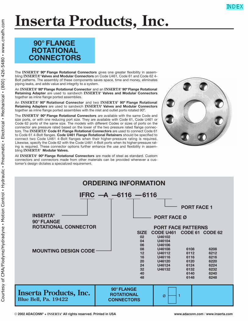
90° FLANGE ROTATIONAL
CONNECTORS
90° FLANGEROTATIONAL
CONNECTORS
ORDERING INFORMATION
IFRC — A — 6116 — 6116
INSERTA®
90° FLANGE ROTATIONAL CONNECTOR
MOUNTING DESIGN CODE
PORT FACE 1
PORT FACE Ø
PORT FACE PATTERNSSIZE CODE U461 CODE 61 CODE 62
02 U4610204 U4610406 U4610608 U46108 6108 620812 U46112 6112 621216 U46116 6116 621620 U46120 6120 622024 U46124 6124 622432 U46132 6132 623240 6140 624048 6148 6248
Ø 1
The INSERTA® 90º Flange Rotational Connectors gives one greater flexibility in assem-bling INSERTA® Valves and Modular Connectors on Code U461, Code 61 and Code 62 4-Bolt patterns. The assembly of these components saves space, time and money, eliminatespiping leaks, and adds value and integrity to a system.
An INSERTA® 90º Flange Rotational Connector and an INSERTA® 90º Flange RotationalRetaining Adapter are used to sandwich INSERTA® Valves and Modular Connectorstogether as inline flange ported assemblies.
An INSERTA® 90º Rotational Connector and two INSERTA® 90º Flange RotationalRetaining Adapters are used to sandwich INSERTA® Valves and Modular Connectorstogether as inline flange ported assemblies with the inlet and outlet ports rotated 90º.
The INSERTA® 90º Flange Rotational Connectors are available with the same Code andsize ports, or with one reducing port size. They are available with Code 61, Code U461 orCode 62 ports of the same size. The models with different Codes or sizes of ports on theconnector are pressure rated based on the lower of the two pressure rated flange connec-tors. The INSERTA® Code 61 Flange Rotational Connectors are used to connect Code 61to Code 61 4-Bolt flanges. Code U461 Flange Rotational Retainers should be specified toconnect two Code U461 4-Bolt flanges when their higher-pressure rating is required.Likewise, specify the Code 62 with the Code U461 4-Bolt ports when its higher-pressure rat-ing is required. These connector options further enhance the use and flexibility in assem-bling INSERTA® Modular Valves.
All INSERTA® 90º Flange Rotational Connectors are made of steel as standard. Customconnectors and connectors made from other materials can be provided whenever a cus-tomer’s design dictates a specialized requirement.
Inserta Products, Inc.Blue Bell, Pa. 19422
Inserta Products, Inc.
© 2002 ADACONN® + INSERTA® All rights reserved. Printed in USA www.adaconn.com / www.inserta.com
Court
esy
of CM
A/F
lodyn
e/H
ydra
dyn
e ▪
Motion C
ontr
ol ▪
Hyd
raulic
▪ P
neu
mat
ic ▪
Ele
ctrica
l ▪
Mec
han
ical
▪ (
800)
426-5
480 ▪
ww
w.c
maf
h.c
om
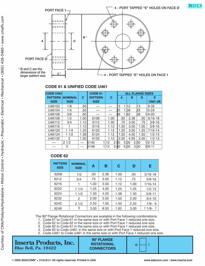
CODE U461 CODE 61 ALL FLANGE SIZESPATTERN NOMINAL C PATTERN C A B D E
SIZE SIZE SIZE UNC-2B
U46102 1/8 .50 — — .13 1.12 .13 8-32U46104 1/4 .50 — — .25 1.38 .25 10-24U46106 3/8 .50 — — .38 1.62 .38 1/4-20U46108 1/2 1.00 6108 1.00 .50 2.38 .50 5/16-18U46112 3/4 1.12 6112 1.00 .75 3.00 .75 3/8-16U46116 1 1.12 6116 1.12 1.00 3.00 1.00 3/8-16U46120 1 1/4 1.25 6120 1.12 1.25 3.50 1.25 7/16-14U46124 1 1/2 1.38 6124 1.12 1.50 4.00 1.50 1/2-13U46132 2 1.50 6132 1.12 2.00 4.50 2.00 1/2-13
— 2 1/2 — 6140 1.12 2.50 5.00 2.50 1/2-13— 3 — 6148 1.12 3.00 6.00 3.00 5/8-11
90° FLANGEROTATIONAL
CONNECTORS
The 90º Flange Rotational Connectors are available in the following combinations:1. Code 61 to Code 61 in the same size or with Port Face 1 reduced one size.2. Code 62 to Code 62 in the same size or with Port Face 1 reduced one size.3. Code 62 to Code 61 in the same size or with Port Face 1 reduced one size.4. Code 62 to Code U461 in the same size or with Port Face 1 reduced one size.5. Code U461 to Code U461 in the same size or with Port Face 1 reduced one size.
C *
B *A D
PORT FACE 14 - PORT TAPPED “E” HOLES ON FACE Ø
4 - PORT TAPPED “E” HOLES ON FACE 1
* B and C are the dimensions of the larger pattern size
PORT FACE Ø
CODE 61 & UNIFIED CODE U461
CODE 62
PATTERNSIZE A B C D
620862126216622062246232
6240
6248
.50
.751.001.251.502.00
2.50
3.00
2.383.003.504.004.505.50
7.00
8.50
1.001.121.121.251.381.50
1.501.62
.50
.751.001.251.502.00
2.503.00
E
5/16-183/8-16
7/16-141/2-135/8-113/4-10
7/8-191 1/8-17
NOMINALSIZE
1/23/41
1 1/41 1/2
2
2 1/23
Ø 1
PORT FACE 1
Inserta Products, Inc.Blue Bell, Pa. 19422
© 2002 ADACONN® + INSERTA® All rights reserved. Printed in USA www.adaconn.com / www.inserta.com
Court
esy
of CM
A/F
lodyn
e/H
ydra
dyn
e ▪
Motion C
ontr
ol ▪
Hyd
raulic
▪ P
neu
mat
ic ▪
Ele
ctrica
l ▪
Mec
han
ical
▪ (
800)
426-5
480 ▪
ww
w.c
maf
h.c
om
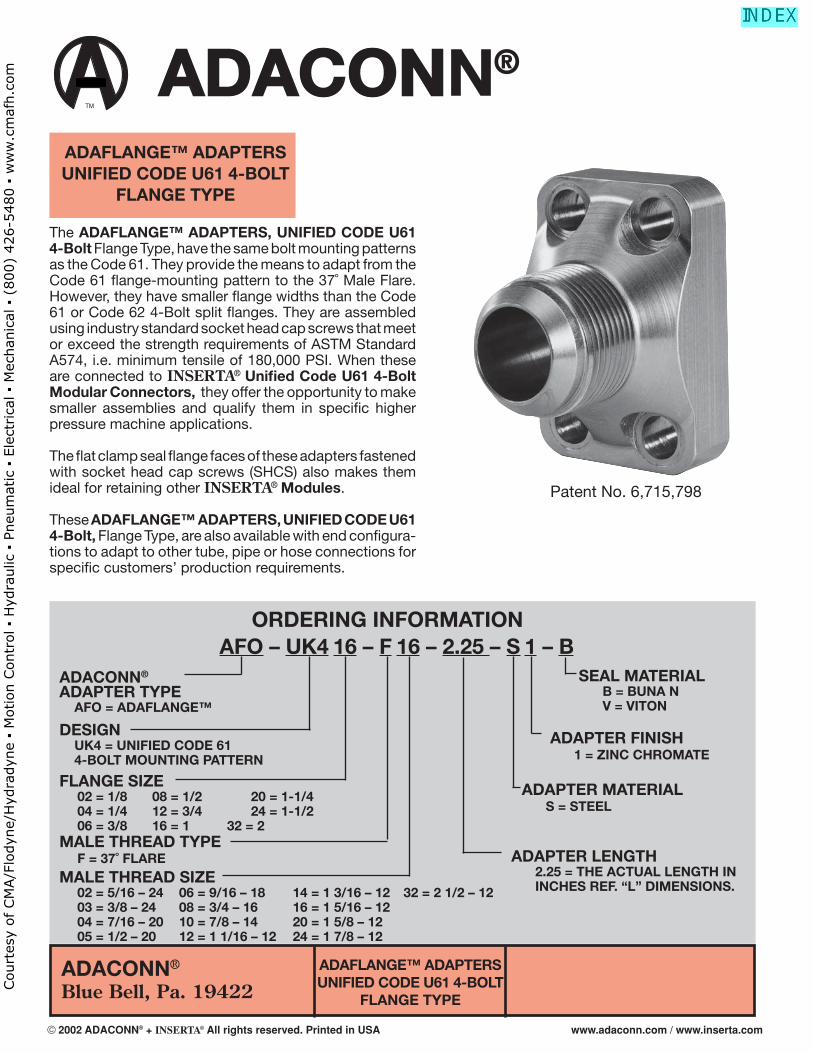
ADACONN®
Blue Bell, Pa. 19422ADAFLANGE™ ADAPTERSUNIFIED CODE U61 4-BOLT
FLANGE TYPE
ORDERING INFORMATIONAFO – UK4 16 – F 16 – 2.25 – S 1 – B
ADACONN®
ADAPTER TYPE AFO = ADAFLANGE™
DESIGN UK4 = UNIFIED CODE 61 4-BOLT MOUNTING PATTERN
MALE THREAD SIZE 02 = 5/16 – 24 06 = 9/16 – 18 14 = 1 3/16 – 12 32 = 2 1/2 – 12 03 = 3/8 – 24 08 = 3/4 – 16 16 = 1 5/16 – 12 04 = 7/16 – 20 10 = 7/8 – 14 20 = 1 5/8 – 12 05 = 1/2 – 20 12 = 1 1/16 – 12 24 = 1 7/8 – 12
The ADAFLANGE™ ADAPTERS, UNIFIED CODE U61 4-Bolt Flange Type, have the same bolt mounting patterns as the Code 61. They provide the means to adapt from the Code 61 fl ange-mounting pattern to the 37˚ Male Flare. However, they have smaller fl ange widths than the Code 61 or Code 62 4-Bolt split fl anges. They are assembled using industry standard socket head cap screws that meet or exceed the strength requirements of ASTM Standard A574, i.e. minimum tensile of 180,000 PSI. When these are connected to INSERTA® Unifi ed Code U61 4-Bolt Modular Connectors, they offer the opportunity to make smaller assemblies and qualify them in specifi c higher pressure machine applications.
The fl at clamp seal fl ange faces of these adapters fastened with socket head cap screws (SHCS) also makes them ideal for retaining other INSERTA® Modules.
These ADAFLANGE™ ADAPTERS, UNIFIED CODE U61 4-Bolt, Flange Type, are also available with end confi gura-tions to adapt to other tube, pipe or hose connections for specifi c customers’ production requirements.
MALE THREAD TYPE F = 37˚ FLARE
SEAL MATERIAL B = BUNA N V = VITON
ADAPTER FINISH 1 = ZINC CHROMATE
ADAPTER MATERIAL S = STEEL
ADAPTER LENGTH 2.25 = THE ACTUAL LENGTH IN INCHES REF. “L” DIMENSIONS.
TM
®
ADAFLANGE™ ADAPTERSUNIFIED CODE U61 4-BOLT
FLANGE TYPE
FLANGE SIZE 02 = 1/8 08 = 1/2 20 = 1-1/4 04 = 1/4 12 = 3/4 24 = 1-1/2 06 = 3/8 16 = 1 32 = 2
Patent No. 6,715,798
© 2002 ADACONN® + INSERTA® All rights reserved. Printed in USA www.adaconn.com / www.inserta.com
Court
esy
of CM
A/F
lodyn
e/H
ydra
dyn
e ▪
Motion C
ontr
ol ▪
Hyd
raulic
▪ P
neu
mat
ic ▪
Ele
ctrica
l ▪
Mec
han
ical
▪ (
800)
426-5
480 ▪
ww
w.c
maf
h.c
om
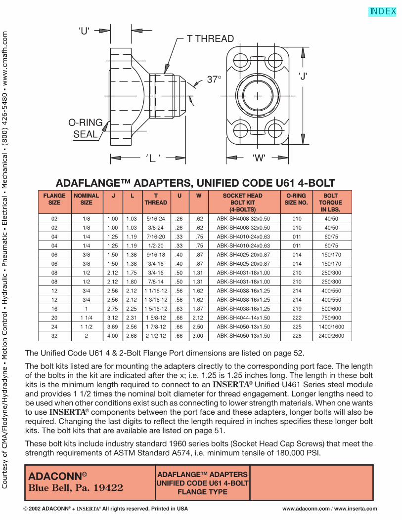
ADACONN®
Blue Bell, Pa. 19422ADAFLANGE™ ADAPTERSUNIFIED CODE U61 4-BOLT
FLANGE TYPE
The Unifi ed Code U61 4 & 2-Bolt Flange Port dimensions are listed on page 52.
The bolt kits listed are for mounting the adapters directly to the corresponding port face. The length of the bolts in the kit are indicated after the x; i.e. 1.25 is 1.25 inches long. The length in these bolt kits is the minimum length required to connect to an INSERTA® Unifi ed U461 Series steel module and provides 1 1/2 times the nominal bolt diameter for thread engagement. Longer lengths need to be used when other conditions exist such as connecting to lower strength materials. When one wants to use INSERTA® components between the port face and these adapters, longer bolts will also be required. Changing the last digits to refl ect the length required in inches specifi es these longer bolt kits. The bolt kits that are available are listed on page 51.
These bolt kits include industry standard 1960 series bolts (Socket Head Cap Screws) that meet the strength requirements of ASTM Standard A574, i.e. minimum tensile of 180,000 PSI.
T THREAD
'J'
'W'
37°
'U'
O-RINGSEAL
FFLLAANNGGEE NNOOMMIINNAALL JJ LL TT UU WW SSOOCCKKEETT HHEEAADD OO--RRIINNGG BBOOLLTTSSIIZZEE SSIIZZEE TTHHRREEAADD BBOOLLTT KKIITT SSIIZZEE NNOO.. TTOORRQQUUEE
((44--BBOOLLTTSS)) IINN LLBBSS..
02 1/8 1.00 1.03 5/16-24 .26 .62 ABK-SH4008-32x0.50 010 40/50
02 1/8 1.00 1.03 3/8-24 .26 .62 ABK-SH4008-32x0.50 010 40/50
04 1/4 1.25 1.19 7/16-20 .33 .75 ABK-SH4010-24x0.63 011 60/75
04 1/4 1.25 1.19 1/2-20 .33 .75 ABK-SH4010-24x0.63 011 60/75
06 3/8 1.50 1.38 9/16-18 .40 .87 ABK-SH4025-20x0.87 014 150/170
06 3/8 1.50 1.38 3/4-16 .40 .87 ABK-SH4025-20x0.87 014 150/170
08 1/2 2.12 1.75 3/4-16 .50 1.31 ABK-SH4031-18x1.00 210 250/300
08 1/2 2.12 1.80 7/8-14 .50 1.31 ABK-SH4031-18x1.00 210 250/300
12 3/4 2.56 2.12 1 1/16-12 .56 1.62 ABK-SH4038-16x1.25 214 400/550
12 3/4 2.56 2.12 1 3/16-12 .56 1.62 ABK-SH4038-16x1.25 214 400/550
16 1 2.75 2.25 1 5/16-12 .63 1.87 ABK-SH4038-16x1.25 219 500/600
20 1 1/4 3.12 2.31 1 5/8-12 .66 2.12 ABK-SH4044-14x1.50 222 750/900
24 1 1/2 3.69 2.56 1 7/8-12 .66 2.50 ABK-SH4050-13x1.50 225 1400/1600
32 2 4.00 2.68 2 1/2-12 .66 3.00 ABK-SH4050-13x1.50 228 2400/2600
ADAFLANGE™ ADAPTERS, UNIFIED CODE U61 4-BOLT
© 2002 ADACONN® + INSERTA® All rights reserved. Printed in USA www.adaconn.com / www.inserta.com
Court
esy
of CM
A/F
lodyn
e/H
ydra
dyn
e ▪
Motion C
ontr
ol ▪
Hyd
raulic
▪ P
neu
mat
ic ▪
Ele
ctrica
l ▪
Mec
han
ical
▪ (
800)
426-5
480 ▪
ww
w.c
maf
h.c
om
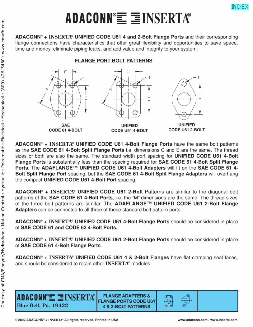
Blue Bell, Pa. 19422
FLANGE ADAPTERS &FLANGE PORTS CODE U61
4 & 2-BOLT PATTERNS
ADACONN® + INSERTA® UNIFIED CODE U61 4 and 2-Bolt Flange Ports and their correspondingflange connections have characteristics that offer great flexibility and opportunities to save space,time and money, eliminate piping leaks, and add value and integrity to your system.
FLANGE PORT BOLT PATTERNS
ADACONN® + INSERTA® UNIFIED CODE U61 4-Bolt Flange Ports have the same bolt patterns as the SAE CODE 61 4-Bolt Split Flange Ports i.e. dimensions C and E are the same. The threadsizes of both are also the same. The standard width port spacing for UNIFIED CODE U61 4-BoltFlange Ports is substantially less than the spacing required for SAE CODE 61 4-Bolt Split FlangePorts. The ADAFLANGE™ UNIFIED CODE U61 4-Bolt Adapters will fit on the SAE CODE 61 4-Bolt Split Flange Port spacing, but the SAE CODE 61 4-Bolt Split Flange Adapters will overhangthe compact UNIFIED CODE U61 4-Bolt Port spacing.
ADACONN® + INSERTA® UNIFIED CODE U61 2-Bolt Patterns are similar to the diagonal bolt patterns of the SAE CODE 61 4-Bolt Ports, i.e. the “M” dimensions are the same. The thread sizesof the three bolt patterns are similar. The ADAFLANGE™ UNIFIED CODE U61 2-Bolt FlangeAdapters can be connected to all three of these standard bolt pattern ports.
ADACONN® + INSERTA® UNIFIED CODE U61 4-Bolt Flange Ports should be considered in placeof SAE CODE 61 and CODE 62 4-Bolt Ports.
ADACONN® + INSERTA® UNIFIED CODE U61 2-Bolt Flange Ports should be considered in placeof SAE CODE 61 4-Bolt Flange Ports.
ADACONN® + INSERTA® UNIFIED CODE U61 4 & 2-Bolt Flanges have flat clamping seal faces,and should be considered to retain other INSERTA® modules.
SAECODE 61 4-BOLT
UNIFIEDCODE U61 4-BOLT
UNIFIEDCODE U61 2-BOLT
® ®
® ®
© 2002 ADACONN® + INSERTA® All rights reserved. Printed in USA www.adaconn.com / www.inserta.com
Court
esy
of CM
A/F
lodyn
e/H
ydra
dyn
e ▪
Motion C
ontr
ol ▪
Hyd
raulic
▪ P
neu
mat
ic ▪
Ele
ctrica
l ▪
Mec
han
ical
▪ (
800)
426-5
480 ▪
ww
w.c
maf
h.c
om
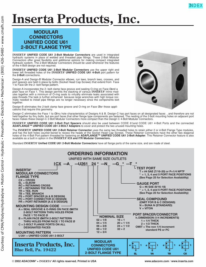
MODULARCONNECTORS
UNIFIED CODE U612-BOLT FLANGE TYPE
INSERTA® UNIFIED CODE U61 2-Bolt Modular Connectors are used in integratedhydraulic systems in place of welded and threaded pipe fittings. These 2-Bolt ModularConnectors offer great flexibility and additional options for making compact integratedhydraulic system. The 2-Bolt Modular Connectors should be used whenever the featuresof the 4-Bolt design are not required.
INSERTA® UNIFIED CODE U61 2-Bolt Modular Connectors use the upper right andlower left threaded holes of the INSERTA® UNIFIED CODE U61 4-Bolt port pattern forthe 2-Bolt connections.
Design-A and Design-B Modular Connector elbows, run tees, branch tees, crosses, andport spacers are held in place by bolts (Socket Head Cap Screws) that extend from Face1 to Face Ø in the 2- bolt flange pattern.
Design-A incorporates the 2- bolt clamp face groove and sealing O-ring on Face Ø and aplain face on Face 1. This design permits the stacking of various INSERTA® inline mod-ules together with a minimum of O-ring seals to virtually eliminate leaks associated withpipe threads.The task is further enhanced because large wrenches with high torque nor-mally needed to install pipe fittings are no longer necessary since the components bolttogether.
Design-B eliminates the 2-bolt clamp face groove and O-ring on Face Ø for those appli-cations that require this geometry.
Design-C eliminates the Face 1 to Ø thru hole characteristics of Designs A & B. Design-C has port faces on all designated faces , and therefore are notheld together by thru bolts, but are port faces that other flange type components are fastened. The nesting of the 2-bolt mounting holes on adjacent portfaces makes these Design-C 2-Bolt Modular Connectors more compact than the Design C 4-Bolt Modular Connectors.
INSERTA® UNIFIED CODE U61 2-Bolt Port Spacers should also be used between CODE 61and CODE U61 4-Bolt Ports and the connectedADAFLANGE™ UNIFIED CODE U61 2-BOLT Adapters to cover and protect the two unused mounting holes.
The INSERTA® UNIFIED CODE U61 2-Bolt Retainer Connector uses the same two threaded holes to retain either 2 or 4-Bolt Flange Type modules,and has the bolt holes counter-bored to recess the heads of the Socket Head Cap Screws. These Retainer Connectors have the other two diagonalholes of the 4-Bolt Port pattern threaded for fastening an ADAFLANGE™ UNIFIED CODE U61 2-Bolt Adapter. This Retainer Connector feature is alsoavailable as a built in option in the INSERTA® ICX and ITR Modular Connectors.
Standard INSERTA® Unified CODE U61 2-Bolt Modular Connectors have all flange ports of the same size, and are made of steel.
MODULARCONNECTORS
UNIFIED CODE U612-BOLT FLANGE TYPE CX
ø
3
1
2
ORDERING INFORMATIONUNIFIED WITH SAME SIZE OUTLETS
ICX — A — U261 24 * — N — G * — T *INSERTA®
MODULAR CONNECTORSFLANGE TYPE
MOUNTING DESIGN CODEA = SEAL GROOVE & O-RING ON FACE Ø WITH
2-BOLT PATTERN THRU HOLES FROMFACE 1 TO FACE Ø
B = PLAIN FACE Ø WITH 2-BOLT PATTERNTHRU HOLES FROM FACE 1 TO FACE Ø
C = 2-BOLT FLANGE PORTS ON ALLDESIGNATED FACES
CX = CROSSEL = ELBOWRC = RETAINING CROSSRT = RETAINING TEE RUNTR = TEE, RUNTB = TEE, BRANCHPS = PORT SPACER (A & B DESIGN)PC = PORT CONNECTOR (C DESIGN)PR = PORT RETAINER (A & B DESIGN)
TEST PORTT = #4 SAE (7/16-20) or P=1/4 NPTF* = 1, 3, 4 and 5 PORT FACE POSITIONS(See Page 25 for Selection Availability)
GAUGE PORT G = #6 SAE (9/16-18)* = 1, 3, 4 and 5 PORT FACE POSITIONS(See Page 25 for Selection Availability)
SEAL COMPOUND(OMIT FOR B & C DESIGNS)N = BUNA N (STANDARD)V = VITON
NOMINAL SIZE02 = 1/8 16 = 104 = 1/4 20 = 1 1/406 = 3/8 24 = 1 1/208 = 1/2 32 = 212 = 3/4
PORT SPACER/CONNECTORh1 DIMENSION (1/4 INCREMENTS)
1 = 1/4 THICK2 = 1/2 THICK
OMIT = The non 1/4 increment standard PS or PC
MOUNTING PATTERNU 261 = UNIFIED CODE U61 2-BOLT
EL
ø 1
2TR
ø 1
2TB
ø
3
1
2
Inserta Products, Inc.Blue Bell, Pa. 19422
Inserta Products, Inc.
© 2002 ADACONN® + INSERTA® All rights reserved. Printed in USA www.adaconn.com / www.inserta.com
Court
esy
of CM
A/F
lodyn
e/H
ydra
dyn
e ▪
Motion C
ontr
ol ▪
Hyd
raulic
▪ P
neu
mat
ic ▪
Ele
ctrica
l ▪
Mec
han
ical
▪ (
800)
426-5
480 ▪
ww
w.c
maf
h.c
om
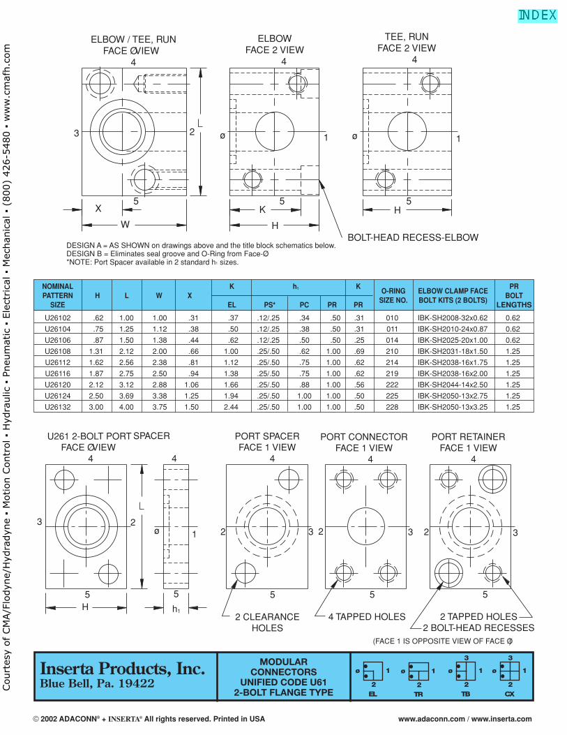
NOMINAL K h1 K PRPATTERN H L W X
O-RING ELBOW CLAMP FACEBOLT
SIZE EL PS* PC PR PRSIZE NO. BOLT KITS (2 BOLTS)
LENGTHS
U26102 .62 1.00 1.00 .31 .37 .12/.25 .34 .50 .31 010 IBK-SH2008-32x0.62 0.62
U26104 .75 1.25 1.12 .38 .50 .12/.25 .38 .50 .31 011 IBK-SH2010-24x0.87 0.62
U26106 .87 1.50 1.38 .44 .62 .12/.25 .50 .50 .25 014 IBK-SH2025-20x1.00 0.62
U26108 1.31 2.12 2.00 .66 1.00 .25/.50 .62 1.00 .69 210 IBK-SH2031-18x1.50 1.25
U26112 1.62 2.56 2.38 .81 1.12 .25/.50 .75 1.00 .62 214 IBK-SH2038-16x1.75 1.25
U26116 1.87 2.75 2.50 .94 1.38 .25/.50 .75 1.00 .62 219 IBK-SH2038-16x2.00 1.25
U26120 2.12 3.12 2.88 1.06 1.66 .25/.50 .88 1.00 .56 222 IBK-SH2044-14x2.50 1.25
U26124 2.50 3.69 3.38 1.25 1.94 .25/.50 1.00 1.00 .50 225 IBK-SH2050-13x2.75 1.25
U26132 3.00 4.00 3.75 1.50 2.44 .25/.50 1.00 1.00 .50 228 IBK-SH2050-13x3.25 1.25
MODULARCONNECTORS
UNIFIED CODE U612-BOLT FLANGE TYPE CX
ø
3
1
2EL
ø 1
2TR
ø 1
2TB
ø
3
1
2
ELBOW / TEE, RUNFACE Ø VIEW
4
ELBOWFACE 2 VIEW
4
TEE, RUNFACE 2 VIEW
4
BOLT-HEAD RECESS-ELBOW
3 2
5
1 ø 1
55
ø
H
W H
KX
U261 2-BOLT PORT FACE Ø VIEW
4
SPACER PORT SPACERFACE 1 VIEW
4
PORT CONNECTORFACE 1 VIEW
4
PORT RETAINERFACE 1 VIEW
4
5
2 CLEARANCEHOLES
5
4 TAPPED HOLES
5
2 TAPPED HOLES2 BOLT-HEAD RECESSES
3 2
5H
1ø
h1
2 3 2 3 2 3
5
4
5
DESIGN A = AS SHOWN on drawings above and the title block schematics below.DESIGN B = Eliminates seal groove and O-Ring from Face-Ø.*NOTE: Port Spacer available in 2 standard h1 sizes.
(FACE 1 IS OPPOSITE VIEW OF FACE Ø)
Inserta Products, Inc.Blue Bell, Pa. 19422
© 2002 ADACONN® + INSERTA® All rights reserved. Printed in USA www.adaconn.com / www.inserta.com
Court
esy
of CM
A/F
lodyn
e/H
ydra
dyn
e ▪
Motion C
ontr
ol ▪
Hyd
raulic
▪ P
neu
mat
ic ▪
Ele
ctrica
l ▪
Mec
han
ical
▪ (
800)
426-5
480 ▪
ww
w.c
maf
h.c
om
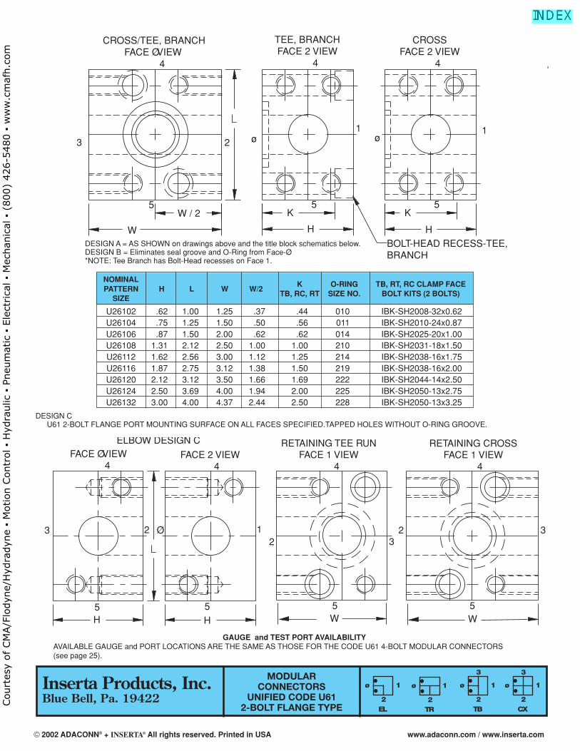
MODULARCONNECTORS
UNIFIED CODE U612-BOLT FLANGE TYPE CX
ø
3
1
2EL
ø 1
2TR
ø 1
2TB
ø
3
1
2
CROSS/TEE, BRANCH FACE Ø VIEW
4
TEE, BRANCHFACE 2 VIEW
4
CROSSFACE 2 VIEW
4
5
3 2 ø1
ø
5 5
1
K
HH
K
W
W / 2
BOLT-HEAD RECESS-TEE,BRANCH
FACE Ø VIEW 4
H H
FACE 2 VIEW 4
RETAINING TEE RUNFACE 1 VIEW
4
RETAINING CROSSFACE 1 VIEW
4
ELBOW DESIGN C
3 2 Ø 12 3
2 3
5 5 5 5W W
DESIGN CU61 2-BOLT FLANGE PORT MOUNTING SURFACE ON ALL FACES SPECIFIED.TAPPED HOLES WITHOUT O-RING GROOVE.
NOMINALPATTERN H L W W/2
K O-RING TB, RT, RC CLAMP FACE
SIZETB, RC, RT SIZE NO. BOLT KITS (2 BOLTS)
U26102 .62 1.00 1.25 .37 .44 010 IBK-SH2008-32x0.62U26104 .75 1.25 1.50 .50 .56 011 IBK-SH2010-24x0.87U26106 .87 1.50 2.00 .62 .62 014 IBK-SH2025-20x1.00U26108 1.31 2.12 2.50 1.00 1.00 210 IBK-SH2031-18x1.50U26112 1.62 2.56 3.00 1.12 1.25 214 IBK-SH2038-16x1.75U26116 1.87 2.75 3.12 1.38 1.50 219 IBK-SH2038-16x2.00U26120 2.12 3.12 3.50 1.66 1.69 222 IBK-SH2044-14x2.50U26124 2.50 3.69 4.00 1.94 2.00 225 IBK-SH2050-13x2.75U26132 3.00 4.00 4.37 2.44 2.50 228 IBK-SH2050-13x3.25
DESIGN A = AS SHOWN on drawings above and the title block schematics below.DESIGN B = Eliminates seal groove and O-Ring from Face-Ø.*NOTE: Tee Branch has Bolt-Head recesses on Face 1.
GAUGE and TEST PORT AVAILABILITYAVAILABLE GAUGE and PORT LOCATIONS ARE THE SAME AS THOSE FOR THE CODE U61 4-BOLT MODULAR CONNECTORS(see page 25).
Inserta Products, Inc.Blue Bell, Pa. 19422
© 2002 ADACONN® + INSERTA® All rights reserved. Printed in USA www.adaconn.com / www.inserta.com
Court
esy
of CM
A/F
lodyn
e/H
ydra
dyn
e ▪
Motion C
ontr
ol ▪
Hyd
raulic
▪ P
neu
mat
ic ▪
Ele
ctrica
l ▪
Mec
han
ical
▪ (
800)
426-5
480 ▪
ww
w.c
maf
h.c
om
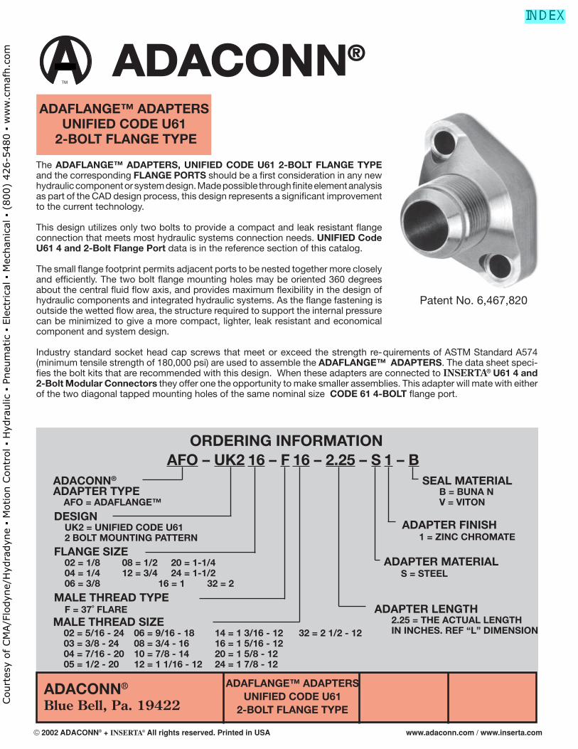
ADACONN®
Blue Bell, Pa. 19422
ADAFLANGE™ ADAPTERSUNIFIED CODE U61
2-BOLT FLANGE TYPE
The ADAFLANGE™ ADAPTERS, UNIFIED CODE U61 2-BOLT FLANGE TYPE and the corresponding FLANGE PORTS should be a fi rst consideration in any new hydraulic component or system design. Made possible through fi nite element analysis as part of the CAD design process, this design represents a signifi cant improvement to the current technology.
This design utilizes only two bolts to provide a compact and leak resistant fl ange connection that meets most hydraulic systems connection needs. UNIFIED Code U61 4 and 2-Bolt Flange Port data is in the reference section of this catalog. The small fl ange footprint permits adjacent ports to be nested together more closely and effi ciently. The two bolt fl ange mounting holes may be oriented 360 degrees about the central fl uid fl ow axis, and provides maximum fl exibility in the design of hydraulic components and integrated hydraulic systems. As the fl ange fastening is outside the wetted fl ow area, the structure required to support the internal pressure can be minimized to give a more compact, lighter, leak resistant and economical component and system design.
Industry standard socket head cap screws that meet or exceed the strength re-quirements of ASTM Standard A574 (minimum tensile strength of 180,000 psi) are used to assemble the ADAFLANGE™ ADAPTERS. The data sheet speci-fi es the bolt kits that are recommended with this design. When these adapters are connected to INSERTA® U61 4 and 2-Bolt Modular Connectors they offer one the opportunity to make smaller assemblies. This adapter will mate with either of the two diagonal tapped mounting holes of the same nominal size CODE 61 4-BOLT fl ange port.
Patent No. 6,467,820
ORDERING INFORMATIONAFO – UK2 16 – F 16 – 2.25 – S 1 – B
ADACONN®
ADAPTER TYPE AFO = ADAFLANGE™
DESIGN UK2 = UNIFIED CODE U61 2 BOLT MOUNTING PATTERN
MALE THREAD SIZE 02 = 5/16 - 24 06 = 9/16 - 18 14 = 1 3/16 - 12 32 = 2 1/2 - 12 03 = 3/8 - 24 08 = 3/4 - 16 16 = 1 5/16 - 12 04 = 7/16 - 20 10 = 7/8 - 14 20 = 1 5/8 - 12 05 = 1/2 - 20 12 = 1 1/16 - 12 24 = 1 7/8 - 12
MALE THREAD TYPE F = 37˚ FLARE
SEAL MATERIAL B = BUNA N V = VITON
ADAPTER FINISH 1 = ZINC CHROMATE
ADAPTER MATERIAL S = STEEL
ADAPTER LENGTH 2.25 = THE ACTUAL LENGTH IN INCHES. REF “L” DIMENSION
TM
®
ADAFLANGE™ ADAPTERSUNIFIED CODE U61
2-BOLT FLANGE TYPE
FLANGE SIZE 02 = 1/8 08 = 1/2 20 = 1-1/4 04 = 1/4 12 = 3/4 24 = 1-1/2 06 = 3/8 16 = 1 32 = 2
© 2002 ADACONN® + INSERTA® All rights reserved. Printed in USA www.adaconn.com / www.inserta.com
Court
esy
of CM
A/F
lodyn
e/H
ydra
dyn
e ▪
Motion C
ontr
ol ▪
Hyd
raulic
▪ P
neu
mat
ic ▪
Ele
ctrica
l ▪
Mec
han
ical
▪ (
800)
426-5
480 ▪
ww
w.c
maf
h.c
om
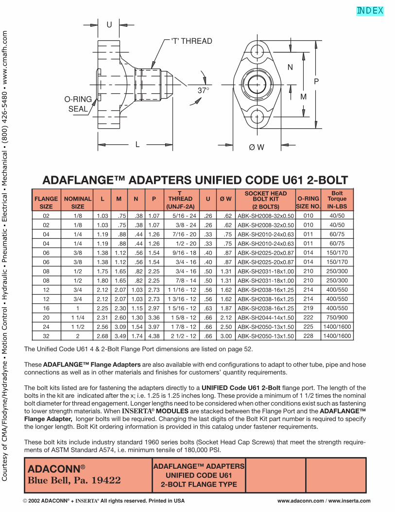
ADACONN®
Blue Bell, Pa. 19422
ADAFLANGE™ ADAPTERSUNIFIED CODE U61
2-BOLT FLANGE TYPE
ADAFLANGE™ ADAPTERS UNIFIED CODE U61 2-BOLT
The Unifi ed Code U61 4 & 2-Bolt Flange Port dimensions are listed on page 52.
These ADAFLANGE™ Flange Adapters are also available with end confi gurations to adapt to other tube, pipe and hose connections as well as in other materials and fi nishes for customers’ quantity requirements.
The bolt kits listed are for fastening the adapters directly to a UNIFIED Code U61 2-Bolt fl ange port. The length of the bolts in the kit are indicated after the x; i.e. 1.25 is 1.25 inches long. These provide a minimum of 1 1/2 times the nominal bolt diameter for thread engagement. Longer lengths need to be considered when other conditions exist such as fastening to lower strength materials. When INSERTA® MODULES are stacked between the Flange Port and the ADAFLANGE™ Flange Adapter, longer bolts will be required. Changing the last digits of the Bolt Kit part number is required to specify the longer length. Bolt Kit ordering information is provided in this catalog under fastener requirements.
These bolt kits include industry standard 1960 series bolts (Socket Head Cap Screws) that meet the strength require-ments of ASTM Standard A574, i.e. minimum tensile of 180,000 PSI.
FLANGESIZE
02
02
04
04
06
06
08
08
12
12
16
20
24
32
NOMINALSIZE
1/8
1/8
1/4
1/4
3/8
3/8
1/2
1/2
3/4
3/4
1
1 1/4
1 1/2
2
M
.75
.75
.88
.88
1.12
1.12
1.65
1.65
2.07
2.07
2.30
2.60
3.09
3.49
L
1.03
1.03
1.19
1.19
1.38
1.38
1.75
1.80
2.12
2.12
2.25
2.31
2.56
2.68
N
.38
.38
.44
.44
.56
.56
.82
.82
1.03
1.03
1.15
1.30
1.54
1.74
P
1.07
1.07
1.26
1.26
1.54
1.54
2.25
2.25
2.73
2.73
2.97
3.36
3.97
4.38
U
.26
.26
.33
.33
.40
.40
.50
.50
.56
.56
.63
.66
.66
.66
T THREAD
(UNJF-2A)
5/16 - 24
3/8 - 24
7/16 - 20
1/2 - 20
9/16 - 18
3/4 - 16
3/4 - 16
7/8 - 14
1 1/16 - 12
1 3/16 - 12
1 5/16 - 12
1 5/8 - 12
1 7/8 - 12
2 1/2 - 12
Ø W
.62
.62
.75
.75
.87
.87
1.31
1.31
1.62
1.62
1.87
2.12
2.50
3.00
SOCKET HEAD BOLT KIT(2 BOLTS)
ABK-SH2008-32x0.50
ABK-SH2008-32x0.50
ABK-SH2010-24x0.63
ABK-SH2010-24x0.63
ABK-SH2025-20x0.87
ABK-SH2025-20x0.87
ABK-SH2031-18x1.00
ABK-SH2031-18x1.00
ABK-SH2038-16x1.25
ABK-SH2038-16x1.25
ABK-SH2038-16x1.25
ABK-SH2044-14x1.50
ABK-SH2050-13x1.50
ABK-SH2050-13x1.50
O-RINGSIZE NO.
010
010
011
011
014
014
210
210
214
214
219
222
225
228
BoltTorqueIN-LBS
40/50
40/50
60/75
60/75
150/170
150/170
250/300
250/300
400/550
400/550
400/550
750/900
1400/1600
1400/1600
'T' THREAD
U
O-RINGSEAL
L Ø W
P
N
M37°
© 2002 ADACONN® + INSERTA® All rights reserved. Printed in USA www.adaconn.com / www.inserta.com
Court
esy
of CM
A/F
lodyn
e/H
ydra
dyn
e ▪
Motion C
ontr
ol ▪
Hyd
raulic
▪ P
neu
mat
ic ▪
Ele
ctrica
l ▪
Mec
han
ical
▪ (
800)
426-5
480 ▪
ww
w.c
maf
h.c
om
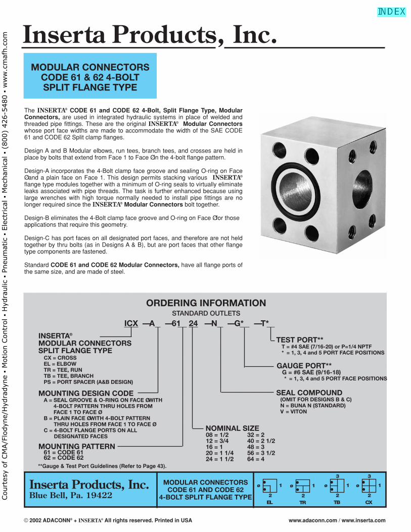
MODULAR CONNECTORSCODE 61 & 62 4-BOLTSPLIT FLANGE TYPE
The INSERTA® CODE 61 and CODE 62 4-Bolt, Split Flange Type, ModularConnectors, are used in integrated hydraulic systems in place of welded andthreaded pipe fittings. These are the original INSERTA® Modular Connectorswhose port face widths are made to accommodate the width of the SAE CODE61 and CODE 62 Split clamp flanges.
Design A and B Modular elbows, run tees, branch tees, and crosses are held inplace by bolts that extend from Face 1 to Face Ø in the 4-bolt flange pattern.
Design-A incorporates the 4-Bolt clamp face groove and sealing O-ring on FaceØ and a plain face on Face 1. This design permits stacking various INSERTA®
flange type modules together with a minimum of O-ring seals to virtually eliminateleaks associated with pipe threads. The task is further enhanced because usinglarge wrenches with high torque normally needed to install pipe fittings are nolonger required since the INSERTA® Modular Connectors bolt together.
Design-B eliminates the 4-Bolt clamp face groove and O-ring on Face Ø for thoseapplications that require this geometry.
Design-C has port faces on all designated port faces, and therefore are not heldtogether by thru bolts (as in Designs A & B), but are port faces that other flangetype components are fastened.
Standard CODE 61 and CODE 62 Modular Connectors, have all flange ports ofthe same size, and are made of steel.
MODULAR CONNECTORSCODE 61 AND CODE 62
4-BOLT SPLIT FLANGE TYPECX
ø
3
1
2
ORDERING INFORMATIONSTANDARD OUTLETS
ICX — A — 61 24 — N — G* — T*
INSERTA®
MODULAR CONNECTORSSPLIT FLANGE TYPE
MOUNTING DESIGN CODEA = SEAL GROOVE & O-RING ON FACE Ø WITH
4-BOLT PATTERN THRU HOLES FROM FACE 1 TO FACE Ø
B = PLAIN FACE Ø WITH 4-BOLT PATTERNTHRU HOLES FROM FACE 1 TO FACE Ø
C = 4-BOLT FLANGE PORTS ON ALLDESIGNATED FACES
CX = CROSSEL = ELBOWTR = TEE, RUNTB = TEE, BRANCHPS = PORT SPACER (A&B DESIGN)
TEST PORT**T = #4 SAE (7/16-20) or P=1/4 NPTF* = 1, 3, 4 and 5 PORT FACE POSITIONS
GAUGE PORT** G = #6 SAE (9/16-18)** = 1, 3, 4 and 5 PORT FACE POSITIONS
SEAL COMPOUND(OMIT FOR DESIGNS B & C)N = BUNA N (STANDARD)V = VITON
NOMINAL SIZE08 = 1/2 32 = 212 = 3/4 40 = 2 1/216 = 1 48 = 320 = 1 1/4 56 = 3 1/224 = 1 1/2 64 = 4
MOUNTING PATTERN61 = CODE 6162 = CODE 62
EL
ø 1
2TR
ø 1
2TB
ø
3
1
2
**Gauge & Test Port Guidelines (Refer to Page 43).
Inserta Products, Inc.Blue Bell, Pa. 19422
Inserta Products, Inc.
© 2002 ADACONN® + INSERTA® All rights reserved. Printed in USA www.adaconn.com / www.inserta.com
Court
esy
of CM
A/F
lodyn
e/H
ydra
dyn
e ▪
Motion C
ontr
ol ▪
Hyd
raulic
▪ P
neu
mat
ic ▪
Ele
ctrica
l ▪
Mec
han
ical
▪ (
800)
426-5
480 ▪
ww
w.c
maf
h.c
om
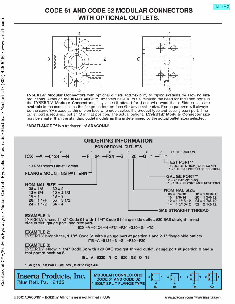
INSERTA® Modular Connectors with optional outlets add flexibility to piping systems by allowing sizereductions. Although the ADAFLANGE™* adapters have all but eliminated the need for threaded ports inthe INSERTA® Modular Connectors, they are still offered for those who want them. Side outlets areavailable in the same size as the flange pattern on face Ø or any smaller size. Flange patterns will alwaysbe the same SAE code as the one on face Ø. To order, select the product type and specify each port. If nooutlet port is required, put an O in that position. The actual optional INSERTA® Modular Connector sizemay be smaller than the standard outlet models as this is determined by the actual outlet sizes selected.
*ADAFLANGE ™ is a trademark of ADACONN®
ORDERING INFORMATIONFOR OPTIONAL OUTLETS
Ø 1 2 3 4 5
ICX — A — 6124 — N — F 24 — F24 — S 20 — G * — T *PORT POSITION
See Standard Outlet Format
FLANGE MOUNTING PATTERN
NOMINAL SIZE08 = 1/2 32 = 212 = 3/4 40 = 2 1/216 = 1 48 = 320 = 1 1/4 56 = 3 1/224 = 1 1/2 64 = 4
TEST PORT**T = #4 SAE (7/16-20) or P=1/4 NPTF * = 1 THRU 5 PORT FACE POSITIONS
GAUGE PORT** G = #6 SAE (9/16-18)* = 1 THRU 5 PORT FACE POSITIONS
SAE STRAIGHT THREAD
NOMINAL SIZE08 = 3/4-16 16 = 1 5/16-1210 = 7/8-14 20 = 1 5/8-1212 = 1 1/16-12 24 = 1 7/8-1214 = 1 3/16-12 32 = 2 1/2-12
EXAMPLE 1:INSERTA® cross, 1 1/2" Code 61 with 1 1/4" Code 61 flange side outlet, #20 SAE straight thread side outlet, gauge port, and test port.
ICX – A – 6124 – N – F24 – F24 – S20 – G4 – T5EXAMPLE 2:INSERTA® branch tee, 1 1/2" Code 61 with a gauge port at position 1 and 2-1" flange side outlets.
ITB – A – 6124 – N – G1 – F20 – F20EXAMPLE 3:INSERTA® elbow, 1 1/4" Code 62 with #20 SAE straight thread outlet, gauge port at position 3 and atest port at position 5.
IEL – A – 6220 – N – O – S20 – G3 – O – T5
CX
ø
3
1
2EL
ø 1
2TR
ø 1
2TB
ø
3
1
2
MODULAR CONNECTORSCODE 61 AND CODE 62
4-BOLT SPLIT FLANGE TYPE
4 4
5 5
3 2 1Ø
**Gauge & Test Port Guidelines (Refer to Page 43).
CODE 61 AND CODE 62 MODULAR CONNECTORS WITH OPTIONAL OUTLETS.
Inserta Products, Inc.Blue Bell, Pa. 19422
© 2002 ADACONN® + INSERTA® All rights reserved. Printed in USA www.adaconn.com / www.inserta.com
Court
esy
of CM
A/F
lodyn
e/H
ydra
dyn
e ▪
Motion C
ontr
ol ▪
Hyd
raulic
▪ P
neu
mat
ic ▪
Ele
ctrica
l ▪
Mec
han
ical
▪ (
800)
426-5
480 ▪
ww
w.c
maf
h.c
om
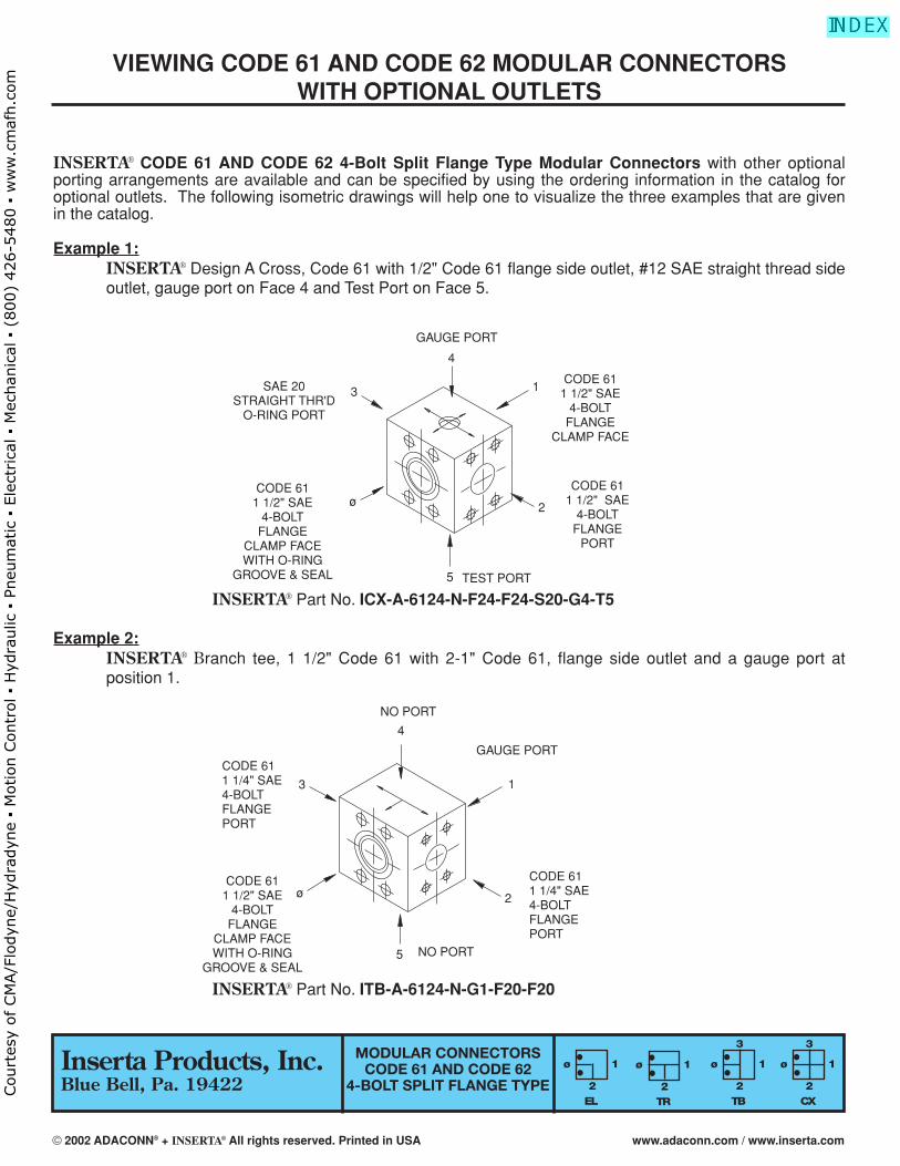
VIEWING CODE 61 AND CODE 62 MODULAR CONNECTORSWITH OPTIONAL OUTLETS
INSERTA® CODE 61 AND CODE 62 4-Bolt Split Flange Type Modular Connectors with other optional porting arrangements are available and can be specified by using the ordering information in the catalog foroptional outlets. The following isometric drawings will help one to visualize the three examples that are givenin the catalog.
Example 1:INSERTA® Design A Cross, Code 61 with 1/2" Code 61 flange side outlet, #12 SAE straight thread sideoutlet, gauge port on Face 4 and Test Port on Face 5.
INSERTA® Part No. ICX-A-6124-N-F24-F24-S20-G4-T5
Example 2:INSERTA® Branch tee, 1 1/2" Code 61 with 2-1" Code 61, flange side outlet and a gauge port at position 1.
INSERTA® Part No. ITB-A-6124-N-G1-F20-F20
GAUGE PORT
SAE 20STRAIGHT THR'D
O-RING PORT
CODE 611 1/2" SAE
4-BOLTFLANGE
CLAMP FACEWITH O-RING
GROOVE & SEAL
CODE 611 1/2" SAE
4-BOLTFLANGE
CLAMP FACE
CODE 611 1/2" SAE
4-BOLTFLANGE
PORT
TEST PORT
3
4
5
2
1
ø
3
ø
5
2
1
4
NO PORT
GAUGE PORTCODE 611 1/4" SAE4-BOLTFLANGEPORT
CODE 611 1/4" SAE4-BOLTFLANGEPORT
NO PORT
CODE 611 1/2" SAE
4-BOLTFLANGE
CLAMP FACEWITH O-RING
GROOVE & SEAL
CX
ø
3
1
2EL
ø 1
2TR
ø 1
2TB
ø
3
1
2
MODULAR CONNECTORSCODE 61 AND CODE 62
4-BOLT SPLIT FLANGE TYPEInserta Products, Inc.Blue Bell, Pa. 19422
© 2002 ADACONN® + INSERTA® All rights reserved. Printed in USA www.adaconn.com / www.inserta.com
Court
esy
of CM
A/F
lodyn
e/H
ydra
dyn
e ▪
Motion C
ontr
ol ▪
Hyd
raulic
▪ P
neu
mat
ic ▪
Ele
ctrica
l ▪
Mec
han
ical
▪ (
800)
426-5
480 ▪
ww
w.c
maf
h.c
om
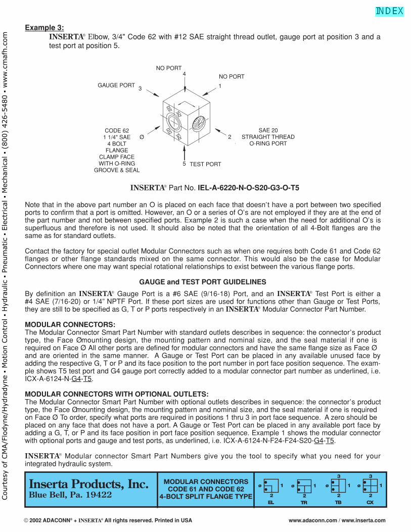
Example 3:INSERTA® Elbow, 3/4" Code 62 with #12 SAE straight thread outlet, gauge port at position 3 and atest port at position 5.
INSERTA® Part No. IEL-A-6220-N-O-S20-G3-O-T5
Note that in the above part number an O is placed on each face that doesn’t have a port between two specifiedports to confirm that a port is omitted. However, an O or a series of O’s are not employed if they are at the end ofthe part number and not between specified ports. Example 2 is such a case when the need for additional O’s issuperfluous and therefore is not used. It should also be noted that the orientation of all 4-Bolt flanges are thesame as for standard outlets.
Contact the factory for special outlet Modular Connectors such as when one requires both Code 61 and Code 62flanges or other flange standards mixed on the same connector. This would also be the case for ModularConnectors where one may want special rotational relationships to exist between the various flange ports.
GAUGE and TEST PORT GUIDELINES
By definition an INSERTA® Gauge Port is a #6 SAE (9/16-18) Port, and an INSERTA® Test Port is either a#4 SAE (7/16-20) or 1/4” NPTF Port. If these port sizes are used for functions other than Gauge or Test Ports,they are still to be specified as G, T or P ports respectively in an INSERTA® Modular Connector Part Number.
MODULAR CONNECTORS:The Modular Connector Smart Part Number with standard outlets describes in sequence: the connector’s producttype, the Face Ø mounting design, the mounting pattern and nominal size, and the seal material if one isrequired on Face Ø. All other ports are defined for modular connectors and have the same flange size as Face Øand are oriented in the same manner. A Gauge or Test Port can be placed in any available unused face byadding the respective G, T or P and its face position to the port number in port face position sequence. The exam-ple shows T5 test port and G4 gauge port correctly added to a modular connector part number as underlined, i.e.ICX-A-6124-N-G4-T5.
MODULAR CONNECTORS WITH OPTIONAL OUTLETS:The Modular Connector Smart Part Number with optional outlets describes in sequence: the connector’s producttype, the Face Ø mounting design, the mounting pattern and nominal size, and the seal material if one is requiredon Face Ø. To order, specify what ports are required in positions 1 thru 3 in port face sequence. A zero should beplaced on any face that does not have a port. A Gauge or Test Port can be placed in any available port face byadding a G, T, or P and its face position in port face position sequence. Example 1 shows the modular connectorwith optional ports and gauge and test ports, as underlined, i.e. ICX-A-6124-N-F24-F24-S20-G4-T5.
INSERTA® Modular connector Smart Part Numbers give you the tool to specify what you need for your integrated hydraulic system.
CX
ø
3
1
2EL
ø 1
2TR
ø 1
2TB
ø
3
1
2
MODULAR CONNECTORSCODE 61 AND CODE 62
4-BOLT SPLIT FLANGE TYPE
SAE 20STRAIGHT THREAD
O-RING PORT
GAUGE PORT
CODE 621 1/4" SAE
4 BOLTFLANGE
CLAMP FACEWITH O-RING
GROOVE & SEAL
NO PORT
3
4
2
5
1
NO PORT
TEST PORT
Ø
Inserta Products, Inc.Blue Bell, Pa. 19422
© 2002 ADACONN® + INSERTA® All rights reserved. Printed in USA www.adaconn.com / www.inserta.com
Court
esy
of CM
A/F
lodyn
e/H
ydra
dyn
e ▪
Motion C
ontr
ol ▪
Hyd
raulic
▪ P
neu
mat
ic ▪
Ele
ctrica
l ▪
Mec
han
ical
▪ (
800)
426-5
480 ▪
ww
w.c
maf
h.c
om
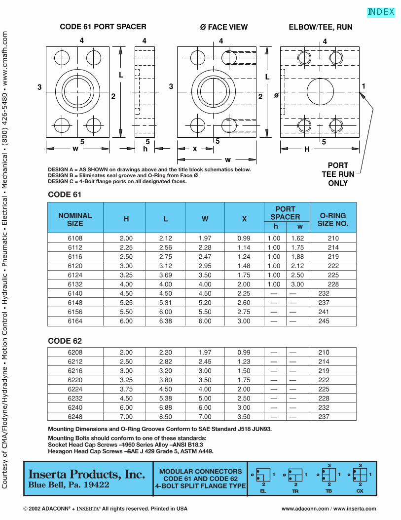
NOMINAL H L W XPORT
O-RINGSIZE
SPACERSIZE NO.h w
6108 2.00 2.12 1.97 0.99 1.00 1.62 2106112 2.25 2.56 2.28 1.14 1.00 1.75 2146116 2.50 2.75 2.47 1.24 1.00 1.88 2196120 3.00 3.12 2.95 1.48 1.00 2.12 2226124 3.25 3.69 3.50 1.75 1.00 2.50 2256132 4.00 4.00 4.00 2.00 1.00 3.00 2286140 4.50 4.50 4.50 2.25 — — 2326148 5.25 5.31 5.20 2.60 — — 2376156 5.50 6.00 5.50 2.75 — — 2416164 6.00 6.38 6.00 3.00 — — 245
Mounting Dimensions and O-Ring Grooves Conform to SAE Standard J518 JUN93.
Mounting Bolts should conform to one of these standards:Socket Head Cap Screws — 1960 Series Alloy — ANSI B18.3Hexagon Head Cap Screws — SAE J 429 Grade 5, ASTM A449.
Inserta Products, Inc.Blue Bell, Pa. 19422
MODULAR CONNECTORSCODE 61 AND CODE 62
4-BOLT SPLIT FLANGE TYPECX
ø
3
1
2EL
ø 1
2TR
ø 1
2TB
ø
3
1
2
CODE 62
DESIGN A = AS SHOWN on drawings above and the title block schematics below.DESIGN B = Eliminates seal groove and O-Ring from Face Ø.DESIGN C = 4-Bolt flange ports on all designated faces.
CODE 61
6208 2.00 2.20 1.97 0.99 — — 2106212 2.50 2.82 2.45 1.23 — — 2146216 3.00 3.20 3.00 1.50 — — 2196220 3.25 3.80 3.50 1.75 — — 2226224 3.75 4.50 4.00 2.00 — — 2256232 4.50 5.38 5.00 2.50 — — 2286240 6.00 6.88 6.00 3.00 — — 2326248 7.00 8.50 7.00 3.50 — — 237
4 4 4 4
32
5w
5h
5x
w
32
L
5H
1ø
L
PORTTEE RUN
ONLY
CODE 61 PORT SPACER Ø FACE VIEW ELBOW/TEE, RUN
© 2002 ADACONN® + INSERTA® All rights reserved. Printed in USA www.adaconn.com / www.inserta.com
Court
esy
of CM
A/F
lodyn
e/H
ydra
dyn
e ▪
Motion C
ontr
ol ▪
Hyd
raulic
▪ P
neu
mat
ic ▪
Ele
ctrica
l ▪
Mec
han
ical
▪ (
800)
426-5
480 ▪
ww
w.c
maf
h.c
om
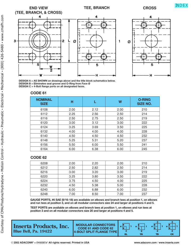
6208 2.00 2.20 2.00 2106212 2.50 2.82 2.50 2146216 3.00 3.20 3.00 2196220 3.25 3.80 3.50 2226224 3.75 4.50 4.00 2256232 4.50 5.38 5.00 2286240 6.00 6.88 6.00 2326248 7.00 8.50 7.00 237
CX
ø
3
1
2EL
ø 1
2TR
ø 1
2TB
ø
3
1
2
MODULAR CONNECTORSCODE 61 AND CODE 62
4-BOLT SPLIT FLANGE TYPE
NOMINALH L W
O-RINGSIZE SIZE NO.
6108 2.00 2.12 2.00 2106112 2.25 2.56 2.50 2146116 2.50 2.75 2.50 2196120 3.00 3.12 3.00 2226124 3.25 3.69 3.50 2256132 4.00 4.00 4.00 2286140 4.50 4.50 4.50 2326148 5.25 5.31 5.20 2376156 5.50 6.00 5.50 2416164 6.00 6.38 6.00 245
CODE 62
DESIGN A = AS SHOWN on drawings above and the title block schematics below.DESIGN B = Eliminates seal groove and O-Ring from Face Ø.DESIGN C = 4-Bolt flange ports on all designated faces.
CODE 61
GAUGE PORTS, #6 SAE (9/16-18) are available on elbows and branch tees at position 1, on elbowsand run tees at position 3, and on all modular connectors size 24 and larger at positions 4 and 5.
TEST PORTS are available on elbows and branch tees at position 1, on elbows and run tees atposition 3 and on all modular connectors size 20 and larger at positions 4 and 5.
END VIEW(TEE, BRANCH, & CROSS)
TEE, BRANCH CROSS
Inserta Products, Inc.Blue Bell, Pa. 19422
© 2002 ADACONN® + INSERTA® All rights reserved. Printed in USA www.adaconn.com / www.inserta.com
Court
esy
of CM
A/F
lodyn
e/H
ydra
dyn
e ▪
Motion C
ontr
ol ▪
Hyd
raulic
▪ P
neu
mat
ic ▪
Ele
ctrica
l ▪
Mec
han
ical
▪ (
800)
426-5
480 ▪
ww
w.c
maf
h.c
om
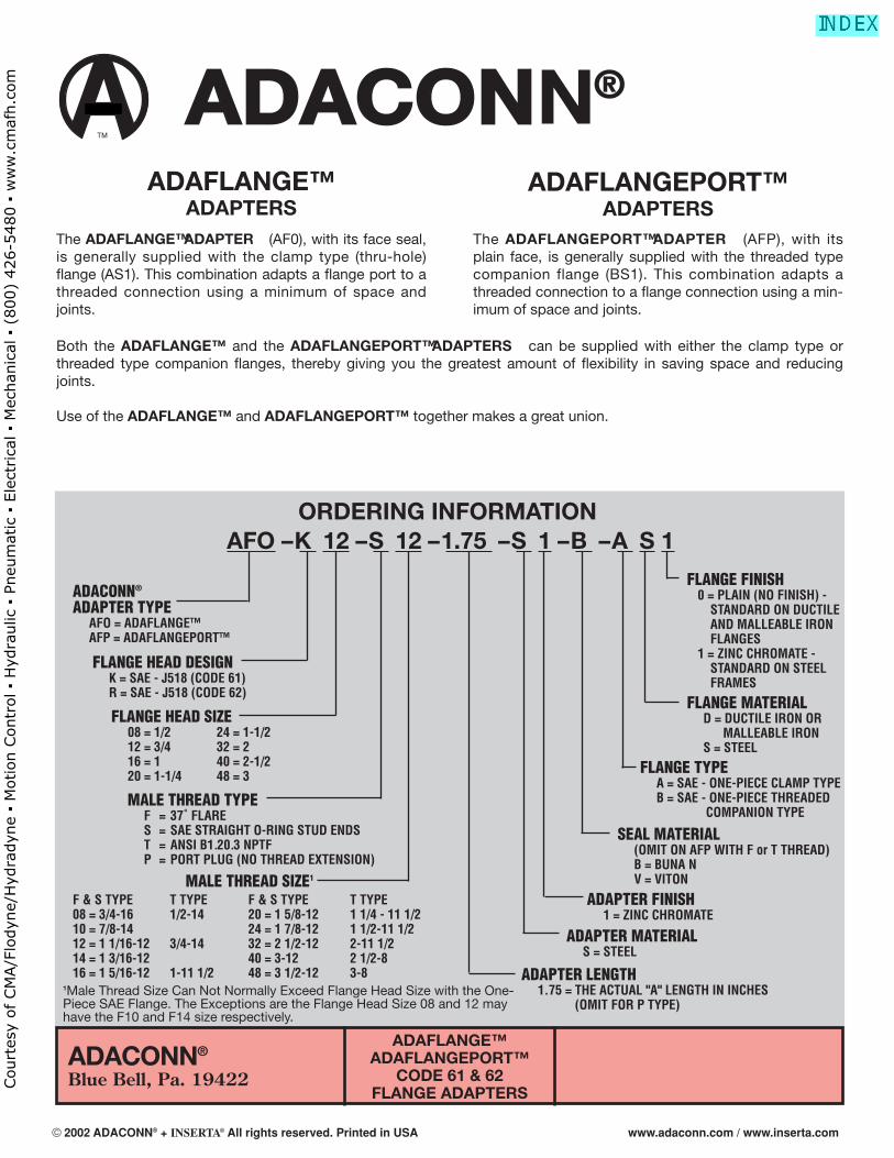
ADAFLANGE™ADAPTERS
ADAFLANGEPORT™ADAPTERS
The ADAFLANGE™ ADAPTER (AF0), with its face seal,is generally supplied with the clamp type (thru-hole)flange (AS1). This combination adapts a flange port to athreaded connection using a minimum of space andjoints.
The ADAFLANGEPORT™ ADAPTER (AFP), with itsplain face, is generally supplied with the threaded typecompanion flange (BS1). This combination adapts athreaded connection to a flange connection using a min-imum of space and joints.
ADACONN®
Blue Bell, Pa. 19422
ADAFLANGE™ADAFLANGEPORT™
CODE 61 & 62FLANGE ADAPTERS
ORDERING INFORMATIONAFO – K 12 – S 12 – 1.75 – S 1 – B – A S 1
ADACONN®
ADAPTER TYPEAFO = ADAFLANGE™AFP = ADAFLANGEPORT™
FLANGE FINISH0 = PLAIN (NO FINISH) -
STANDARD ON DUCTILEAND MALLEABLE IRONFLANGES
1 = ZINC CHROMATE -STANDARD ON STEELFRAMES
FLANGE MATERIALD = DUCTILE IRON OR
MALLEABLE IRONS = STEEL
FLANGE TYPEA = SAE - ONE-PIECE CLAMP TYPEB = SAE - ONE-PIECE THREADED
COMPANION TYPE
SEAL MATERIAL(OMIT ON AFP WITH F or T THREAD)B = BUNA NV = VITON
ADAPTER FINISH1 = ZINC CHROMATE
ADAPTER MATERIALS = STEEL
ADAPTER LENGTH1.75 = THE ACTUAL "A" LENGTH IN INCHES
(OMIT FOR P TYPE)
FLANGE HEAD DESIGNK = SAE - J518 (CODE 61)R = SAE - J518 (CODE 62)
FLANGE HEAD SIZE08 = 1/2 24 = 1-1/212 = 3/4 32 = 216 = 1 40 = 2-1/220 = 1-1/4 48 = 3
MALE THREAD TYPEF = 37˚ FLARES = SAE STRAIGHT O-RING STUD ENDST = ANSI B1.20.3 NPTFP = PORT PLUG (NO THREAD EXTENSION)
MALE THREAD SIZE1
F & S TYPE T TYPE F & S TYPE T TYPE08 = 3/4-16 1/2-14 20 = 1 5/8-12 1 1/4 - 11 1/210 = 7/8-14 24 = 1 7/8-12 1 1/2-11 1/212 = 1 1/16-12 3/4-14 32 = 2 1/2-12 2-11 1/214 = 1 3/16-12 40 = 3-12 2 1/2-816 = 1 5/16-12 1-11 1/2 48 = 3 1/2-12 3-8
TM
®
Both the ADAFLANGE™ and the ADAFLANGEPORT™ ADAPTERS can be supplied with either the clamp type orthreaded type companion flanges, thereby giving you the greatest amount of flexibility in saving space and reducingjoints.
Use of the ADAFLANGE™ and ADAFLANGEPORT™ together makes a great union.
1Male Thread Size Can Not Normally Exceed Flange Head Size with the One-Piece SAE Flange. The Exceptions are the Flange Head Size 08 and 12 mayhave the F10 and F14 size respectively.
© 2002 ADACONN® + INSERTA® All rights reserved. Printed in USA www.adaconn.com / www.inserta.com
Court
esy
of CM
A/F
lodyn
e/H
ydra
dyn
e ▪
Motion C
ontr
ol ▪
Hyd
raulic
▪ P
neu
mat
ic ▪
Ele
ctrica
l ▪
Mec
han
ical
▪ (
800)
426-5
480 ▪
ww
w.c
maf
h.c
om
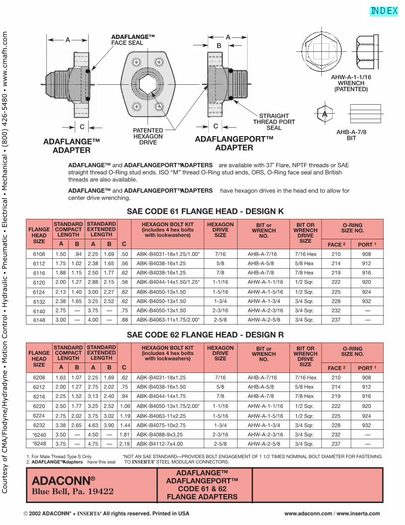
ADACONN®
Blue Bell, Pa. 19422
ADAFLANGE™ADAPTER
ADAFLANGEPORT™ADAPTER
1. For Male Thread Type S Only *NOT AN SAE STANDARD—PROVIDES BOLT ENGAGEMENT OF 1 1/2 TIMES NOMINAL BOLT DIAMETER FOR FASTENING2. ADAFLANGE™ Adapters have this seal TO INSERTA® STEEL MODULAR CONNECTORS.
ADAFLANGE™ and ADAFLANGEPORT™ ADAPTERS are available with 37˚ Flare, NPTF threads or SAEstraight thread O-Ring stud ends. ISO “M” thread O-Ring stud ends, ORS, O-Ring face seal and Britishthreads are also available.
ADAFLANGE™ and ADAFLANGEPORT™ ADAPTERS have hexagon drives in the head end to allow forcenter drive wrenching.
A AB
ADAFLANGE™FACE SEAL
PATENTEDHEXAGON
DRIVE
STRAIGHTTHREAD PORT
SEAL
AHW-A-1-1/16WRENCH
(PATENTED)
AHB-A-7/8BIT
C C
FLANGEHEADSIZE
STANDARDCOMPACTLENGTH
STANDARDEXTENDED
LENGTH
HEXAGONDRIVE SIZE
BIT orWRENCH
NO.
BIT ORWRENCH
DRIVESIZE
FACE 2 PORT 1
O-RINGSIZE NO.
HEXAGON BOLT KIT(includes 4 hex bolts
with lockwashers)
6108
6112
6116
6120
6124
6132
6140
6148
A B B CA
1.50 .94 2.25 1.69 .50 ABK-B4031-18x1.25/1.00* 7/16 AHB-A-7/16 7/16 Hex 210 908
1.75 1.02 2.38 1.65 .56 ABK-B4038-16x1.25 5/8 AHB-A-5/8 5/8 Hex 214 912
1.88 1.15 2.50 1.77 .62 ABK-B4038-16x1.25 7/8 AHB-A-7/8 7/8 Hex 219 916
2.00 1.27 2.88 2.15 .56 ABK-B4044-14x1.50/1.25* 1-1/16 AHW-A-1-1/16 1/2 Sqr. 222 920
2.13 1.40 3.00 2.27 .62 ABK-B4050-13x1.50 1-5/16 AHW-A-1-5/16 1/2 Sqr. 225 924
2.38 1.65 3.25 2.52 .62 ABK-B4050-13x1.50 1-3/4 AHW-A-1-3/4 3/4 Sqr. 228 932
2.75 — 3.75 — .75 ABK-B4050-13x1.50 2-3/16 AHW-A-2-3/16 3/4 Sqr. 232 —
3.00 — 4.00 — .88 ABK-B4063-11x1.75/2.00* 2-5/8 AHW-A-2-5/8 3/4 Sqr. 237 —
SAE CODE 61 FLANGE HEAD - DESIGN K
FLANGEHEADSIZE
STANDARDCOMPACTLENGTH
STANDARDEXTENDED
LENGTH
HEXAGONDRIVE SIZE
BIT orWRENCH
NO.
BIT ORWRENCH
DRIVESIZE
FACE 2 PORT 1
O-RINGSIZE NO.
HEXAGON BOLT KIT(includes 4 hex bolts
with lockwashers)
6208
6212
6216
6220
6224
6232
*6240
*6248
A B B CA
1.63 1.07 2.25 1.69 .62 ABK-B4031-18x1.25 7/16 AHB-A-7/16 7/16 Hex 210 908
2.00 1.27 2.75 2.02 .75 ABK-B4038-16x1.50 5/8 AHB-A-5/8 5/8 Hex 214 912
2.25 1.52 3.13 2.40 .94 ABK-B4044-14x1.75 7/8 AHB-A-7/8 7/8 Hex 219 916
2.50 1.77 3.25 2.52 1.06 ABK-B4050-13x1.75/2.00* 1-1/16 AHW-A-1-1/16 1/2 Sqr. 222 920
2.75 2.02 3.75 3.02 1.19 ABK-B4063-11x2.25 1-5/16 AHW-A-1-5/16 1/2 Sqr. 225 924
3.38 2.65 4.63 3.90 1.44 ABK-B4075-10x2.75 1-3/4 AHW-A-1-3/4 3/4 Sqr. 228 932
3.50 — 4.50 — 1.81 ABK-B4088-9x3.25 2-3/16 AHW-A-2-3/16 3/4 Sqr. 232 —
3.75 — 4.75 — 2.19 ABK-B4112-7x4.00 2-5/8 AHW-A-2-5/8 3/4 Sqr. 237 —
SAE CODE 62 FLANGE HEAD - DESIGN R
A
ADAFLANGE™ADAFLANGEPORT™
CODE 61 & 62FLANGE ADAPTERS
© 2002 ADACONN® + INSERTA® All rights reserved. Printed in USA www.adaconn.com / www.inserta.com
Court
esy
of CM
A/F
lodyn
e/H
ydra
dyn
e ▪
Motion C
ontr
ol ▪
Hyd
raulic
▪ P
neu
mat
ic ▪
Ele
ctrica
l ▪
Mec
han
ical
▪ (
800)
426-5
480 ▪
ww
w.c
maf
h.c
om
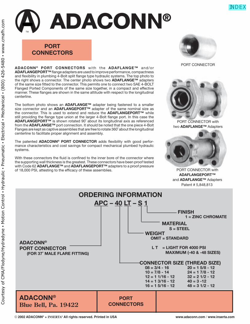
ADACONN®
Blue Bell, Pa. 19422PORT
CONNECTORS
ORDERING INFORMATIONAPC – 40 LT – S 1
ADACONN®
PORT CONNECTOR (FOR 37˚ MALE FLARE FITTING)
CONNECTOR SIZE (THREAD SIZE) 08 = 3/4 - 16 20 = 1 5/8 - 12 10 = 7/8 - 14 24 = 1 7/8 - 12 12 = 1 1/16 - 12 32 = 2 1/2 - 12 14 = 1 3/16 - 12 40 = 3 -12 16 = 1 5/16 - 12 48 = 3 1/2 - 12
ADACONN® PORT CONNECTORS with the ADAFLANGE™ and/or ADAFLANGEPORT™ fl ange adapters are used to improve performance, compactness and fl exibility in plumbing 4-Bolt split fl ange type hydraulic systems. The top photo to the right shows a connector. The center photo shows two ADAFLANGE™ adapters of the same size fi tted to the connector. This permits one to connect two SAE 4-BOLT Flanged Ported Components of the same size together, in a compact and effective manner. These fl anges are shown in the same attitude with respect to the longitudinal centerline.
The bottom photo shows an ADAFLANGE™ adapter being fastened to a smaller size connector and an ADAFLANGEPORT™ adapter of the same nominal size as the connector. This is used to extend and reduce the ADAFLANGEPORT™ while still providing the fl ange type union at the larger 4-Bolt fl ange port. In this case the ADAFLANGEPORT™ is shown rotated 90˚ about its longitudinal axis as referenced from the ADAFLANGE™ port connection. It should be noted that the one piece 4-Bolt Flanges are kept as captive assemblies that are free to rotate 360˚ about the longitudinal centerline to facilitate proper alignment and assembly.
The patented ADACONN® PORT CONNECTOR adds fl exibility with good perfor-mance characteristics and cost savings for compact mechanical plumbed hydraulic systems.
With these connectors the fl uid is confi ned to the inner bore of the connector where the supporting wall thickness is the greatest. These connectors have been proof tested with Code 62 ADAFLANGE™ and ADAFLANGEPORT™ adapters to a proof pressure of 18,000 PSI, attesting to the effi cacy of these assemblies.
FINISH 1 = ZINC CHROMATE MATERIAL
S = STEEL WEIGHT OMIT = STANDARD
L T = LIGHT FOR 4000 PSI MAXIMUM (-40 & -48 SIZES)
PORTCONNECTORS
Patent # 5,848,813
TM
®
PORT CONNECTOR
PORT CONNECTOR withtwo ADAFLANGE™ Adapters
PORT CONNECTOR with ADAFLANGEPORT™
and ADAFLANGE™ Adapters
© 2002 ADACONN® + INSERTA® All rights reserved. Printed in USA www.adaconn.com / www.inserta.com
Court
esy
of CM
A/F
lodyn
e/H
ydra
dyn
e ▪
Motion C
ontr
ol ▪
Hyd
raulic
▪ P
neu
mat
ic ▪
Ele
ctrica
l ▪
Mec
han
ical
▪ (
800)
426-5
480 ▪
ww
w.c
maf
h.c
om
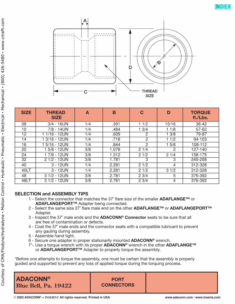
ADACONN®
Blue Bell, Pa. 19422PORT
CONNECTORS
SELECTION and ASSEMBLY TIPS 1 - Select the connector that matches the 37˚ fl are size of the smaller ADAFLANGE™ or ADAFLANGEPORT™ Adapter being connected. 2 - Select the same size 37˚ fl are male end on the other ADAFLANGE™ or ADAFLANGEPORT™ Adapter. 3 - Inspect the 37˚ male ends and the ADACONN® Connector seats to be sure that all are free of contamination or defects. 4 - Coat the 37˚ male ends and the connector seats with a compatible lubricant to prevent any gauling during assembly. 5 - Assemble hand tight. 6 - Secure one adapter in proper stationarily mounted ADACONN® wrench. 7*- Use a torque wrench with its proper ADACONN® wrench in the other ADAFLANGE™ or ADAFLANGEPORT™ Adapter to properly torque the assembly.
*Before one attempts to torque the assembly, one must be certain that the assembly is properlyguided and supported to prevent any loss of applied torque during the torquing process.
08 3/4 - 16UN 1/4 .391 1 1/2 15/16 38-42 10 7/8 - 14UN 1/4 .484 1 3/4 1 1/8 57-62 12 1 1/16 - 12UN 1/4 .609 2 1 3/8 79-87 14 1 3/16 - 12UN 1/4 .718 2 1 1/2 94-103 16 1 5/16 - 12UN 1/4 .844 2 1 5/8 108-112 20 1 5/8 - 12UN 3/8 1.078 2 1/4 2 127-140 24 1 7/8 - 12UN 3/8 1.312 2 1/2 2 1/4 158-175 32 2 1/2 - 12UN 3/8 1.781 3 3 245-258 40 3 - 12UN 1/4 2.281 2 1/2 4 312-328 40LT 3 - 12UN 1/4 2.281 2 1/2 3 1/2 312-328 48 3 1/2 - 12UN 3/8 2.781 2 3/4 5 376-392 48LT 3 1/2 - 12UN 3/8 2.781 2 3/4 4 376-392
SIZE THREAD A B C D TORQUE SIZE ft./Lbs.
© 2002 ADACONN® + INSERTA® All rights reserved. Printed in USA www.adaconn.com / www.inserta.com
Court
esy
of CM
A/F
lodyn
e/H
ydra
dyn
e ▪
Motion C
ontr
ol ▪
Hyd
raulic
▪ P
neu
mat
ic ▪
Ele
ctrica
l ▪
Mec
han
ical
▪ (
800)
426-5
480 ▪
ww
w.c
maf
h.c
om
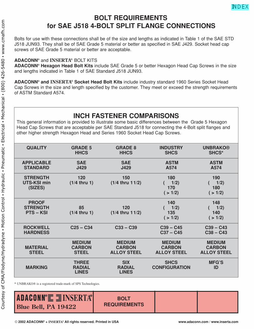
BOLT REQUIREMENTS for SAE J518 4-BOLT SPLIT FLANGE CONNECTIONS
Bolts for use with these connections shall be of the size and lengths as indicated in Table 1 of the SAE STDJ518 JUN93. They shall be of SAE Grade 5 material or better as specified in SAE J429. Socket head capscrews of SAE Grade 5 material or better are acceptable.
ADACONN® and INSERTA® BOLT KITS ADACONN® Hexagon Head Bolt Kits include SAE Grade 5 or better Hexagon Head Cap Screws in the sizeand lengths indicated in Table 1 of SAE Standard J518 JUN93.
ADACONN® and INSERTA® Socket Head Bolt Kits include industry standard 1960 Series Socket HeadCap Screws in the size and length specified by the customer. They meet or exceed the strength requirementsof ASTM Standard A574.
® ®
Blue Bell, PA 19422BOLT
REQUIREMENTS
INCH FASTENER COMPARISONSThis general information is provided to illustrate some basic differences between the Grade 5 HexagonHead Cap Screws that are acceptable per SAE Standard J518 for connecting the 4-Bolt split flanges andother higher strength Hexagon Head and Series 1960 Socket Head Cap Screws.
QUALITY GRADE 5 GRADE 8 INDUSTRY UNBRAKO®HHCS HHCS SHCS SHCS*
APPLICABLE SAE SAE ASTM ASTMSTANDARD J429 J429 A574 A574
STRENGTH 120 150 180 190UTS-KSI min (1/4 thru 1) (1/4 thru 11/2) ( ≤ 1/2) ( ≤ 1/2)
(SIZES) 170 180( > 1/2) ( > 1/2)
PROOF 140 148STRENGTH 85 120 ( ≤ 1/2) ( ≤ 1/2)PTS – KSI (1/4 thru 1) (1/4 thru 11/2) 135 140
( > 1/2) ( > 1/2)
ROCKWELL C25 – C34 C33 – C39 C39 – C45 C39 – C43HARDNESS C37 – C45 C38 – C43
MEDIUM MEDIUM MEDIUM MEDIUMMATERIAL CARBON CARBON CARBON CARBON
STEEL STEEL ALLOY STEEL ALLOY STEEL ALLOY STEEL
THREE SIX SHCS MFG’SMARKING RADIAL RADIAL CONFIGURATION ID
LINES LINES
* UNBRAKO® is a registered trade-mark of SPS Technologies.
© 2002 ADACONN® + INSERTA® All rights reserved. Printed in USA www.adaconn.com / www.inserta.com
Court
esy
of CM
A/F
lodyn
e/H
ydra
dyn
e ▪
Motion C
ontr
ol ▪
Hyd
raulic
▪ P
neu
mat
ic ▪
Ele
ctrica
l ▪
Mec
han
ical
▪ (
800)
426-5
480 ▪
ww
w.c
maf
h.c
om
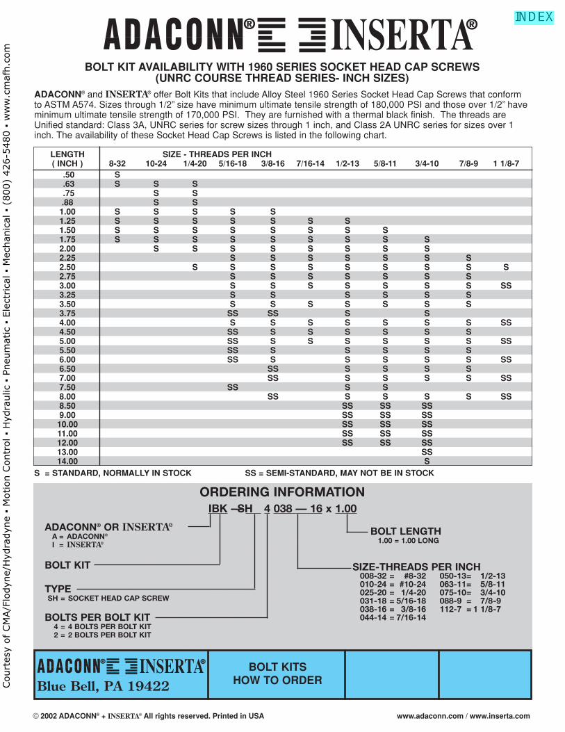
BOLT KIT AVAILABILITY WITH 1960 SERIES SOCKET HEAD CAP SCREWS(UNRC COURSE THREAD SERIES- INCH SIZES)
ADACONN® and INSERTA® offer Bolt Kits that include Alloy Steel 1960 Series Socket Head Cap Screws that conformto ASTM A574. Sizes through 1/2” size have minimum ultimate tensile strength of 180,000 PSI and those over 1/2” haveminimum ultimate tensile strength of 170,000 PSI. They are furnished with a thermal black finish. The threads areUnified standard: Class 3A, UNRC series for screw sizes through 1 inch, and Class 2A UNRC series for sizes over 1inch. The availability of these Socket Head Cap Screws is listed in the following chart.
LENGTH SIZE - THREADS PER INCH( INCH ) 8-32 10-24 1/4-20 5/16-18 3/8-16 7/16-14 1/2-13 5/8-11 3/4-10 7/8-9 1 1/8-7
.50 S
.63 S S S
.75 S S.88 S S1.00 S S S S S1.25 S S S S S S S1.50 S S S S S S S S1.75 S S S S S S S S S2.00 S S S S S S S S2.25 S S S S S S S2.50 S S S S S S S S S2.75 S S S S S S S3.00 S S S S S S S SS3.25 S S S S S S3.50 S S S S S S S3.75 SS SS S S4.00 S S S S S S S SS4.50 SS S S S S S S5.00 SS S S S S S S SS5.50 SS S S S S S6.00 SS S S S S S SS6.50 SS S S S S7.00 SS S S S S SS7.50 SS S S8.00 SS S S S S SS8.50 SS SS SS9.00 SS SS SS
10.00 SS SS SS11.00 SS SS SS12.00 SS SS SS13.00 SS14.00 S
S = STANDARD, NORMALLY IN STOCK SS = SEMI-STANDARD, MAY NOT BE IN STOCK
® ®
® ®
Blue Bell, PA 19422BOLT KITS
HOW TO ORDER
ORDERING INFORMATIONIBK — SH 4 038 — 16 x 1.00
ADACONN® OR INSERTA®
A = ADACONN®
I = INSERTA®
TYPESH = SOCKET HEAD CAP SCREW
BOLTS PER BOLT KIT4 = 4 BOLTS PER BOLT KIT2 = 2 BOLTS PER BOLT KIT
BOLT KIT
BOLT LENGTH1.00 = 1.00 LONG
SIZE-THREADS PER INCH008-32 = #8-32 050-13= 1/2-13010-24 = #10-24 063-11= 5/8-11025-20 = 1/4-20 075-10= 3/4-10031-18 = 5/16-18 088-9 = 7/8-9038-16 = 3/8-16 112-7 = 1 1/8-7044-14 = 7/16-14
© 2002 ADACONN® + INSERTA® All rights reserved. Printed in USA www.adaconn.com / www.inserta.com
Court
esy
of CM
A/F
lodyn
e/H
ydra
dyn
e ▪
Motion C
ontr
ol ▪
Hyd
raulic
▪ P
neu
mat
ic ▪
Ele
ctrica
l ▪
Mec
han
ical
▪ (
800)
426-5
480 ▪
ww
w.c
maf
h.c
om
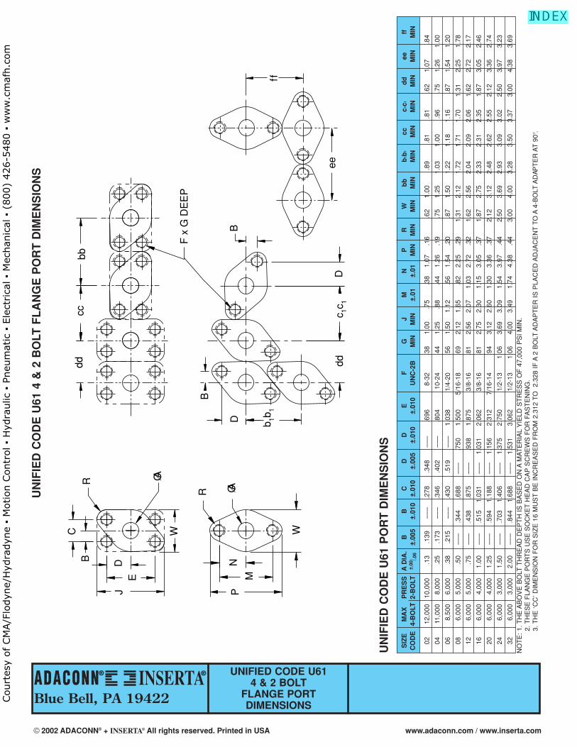
® ®
Blue Bell, PA 19422
UNIFIED CODE U614 & 2 BOLT
FLANGE PORTDIMENSIONS
RB
JD
E
ØA
W
ddcc
bb
F x
G D
EE
P
ØAR
PN
M
W
B
B
Ddd
D
c 1c1
b 1b1
ff
ee
C
UN
IFIE
D C
OD
E U
61 4
& 2
BO
LT F
LA
NG
E P
OR
T D
IME
NS
ION
S
SIZ
EM
AX
PR
ES
SA
DIA
.B
BC
DD
EF
GJ
MN
PR
Wb
bb
1 b1
ccc1
c1d
dee
ffC
OD
E4-
BO
LT2-
BO
LT±.
00/ .0
6±.
005
±.01
0±.
010
±.00
5±.
010
±.01
0U
NC
-2B
MIN
MIN
±.01
±.01
MIN
MIN
MIN
MIN
MIN
MIN
MIN
MIN
MIN
MIN
0212
,000
10,0
00.1
3.1
39–
– –
.278
.348
– –
–.6
968-
32.3
81.
00.7
5.3
81.
07.1
6.6
21.
00.8
9.8
1.8
1.6
21.
07.8
4
0411
,000
8,00
0.2
5.1
73–
– –
.346
.402
– –
–.8
0410
-24
.44
1.25
.88
.44
1.26
.19
.75
1.25
1.03
1.00
.96
.75
1.26
1.00
068,
500
6,00
0.3
8.2
15–
– –
.430
.519
– –
–1.
038
1/4-
20.5
61.
501.
12.5
61.
54.2
0.8
71.
501.
221.
181.
16.8
71.
541.
20
086,
000
5,00
0.5
0–
– –
.344
.688
– –
–.7
501.
500
5/16
-18
.69
2.12
1.65
.82
2.25
.29
1.31
2.12
1.72
1.71
1.70
1.31
2.25
1.78
126,
000
5,00
0.7
5–
– –
.438
.875
– –
–.9
381.
875
3/8-
16.8
12.
562.
071.
032.
72.3
21.
622.
562.
042.
092.
061.
622.
722.
17
166,
000
4,00
01.
00–
– –
.515
1.03
1–
– –
1.03
12.
062
3/8-
16.8
12.
752.
301.
153.
05.3
71.
872.
752.
332.
312.
351.
873.
052.
46
206,
000
4,00
01.
25–
– –
.594
1.18
8–
– –
1.15
62.
312
7/16
-14
.94
3.12
2.60
1.30
3.36
.37
2.12
3.12
2.48
2.62
2.55
2.12
3.36
2.74
246,
000
3,00
01.
50–
– –
.703
1.40
6–
– –
1.37
52.
750
1/2-
131.
063.
693.
091.
543.
97.4
42.
503.
692.
933.
093.
022.
503.
973.
23
326,
000
3,00
02.
00–
– –
.844
1.68
8–
– –
1.53
13.
062
1/2-
131.
064.
003.
491.
744.
38.4
43.
004.
003.
283.
503.
373.
004.
383.
69
UN
IFIE
D C
OD
E U
61 P
OR
T D
IME
NS
ION
S
NO
TE
: 1.
TH
E A
BO
VE
BO
LT T
HR
EA
D D
EP
TH
IS
BA
SE
D O
N A
MA
TE
RIA
L Y
IELD
ST
RE
SS
OF
47,
000
PS
I M
IN.
2. T
HE
SE
FLA
NG
E P
OR
TS
US
E S
OC
KE
T H
EA
D C
AP
SC
RE
WS
FO
R F
AS
TE
NIN
G.
3. T
HE
‘C
C’ D
IME
NS
ION
FO
R S
IZE
16
MU
ST
BE
IN
CR
EA
SE
D F
RO
M 2
.312
TO
2.
328
IF A
2 B
OLT
AD
AP
TE
R I
S P
LAC
ED
AD
JAC
EN
T T
O A
4-B
OLT
AD
APT
ER
AT
90°
.
© 2002 ADACONN® + INSERTA® All rights reserved. Printed in USA www.adaconn.com / www.inserta.com
Court
esy
of CM
A/F
lodyn
e/H
ydra
dyn
e ▪
Motion C
ontr
ol ▪
Hyd
raulic
▪ P
neu
mat
ic ▪
Ele
ctrica
l ▪
Mec
han
ical
▪ (
800)
426-5
480 ▪
ww
w.c
maf
h.c
om
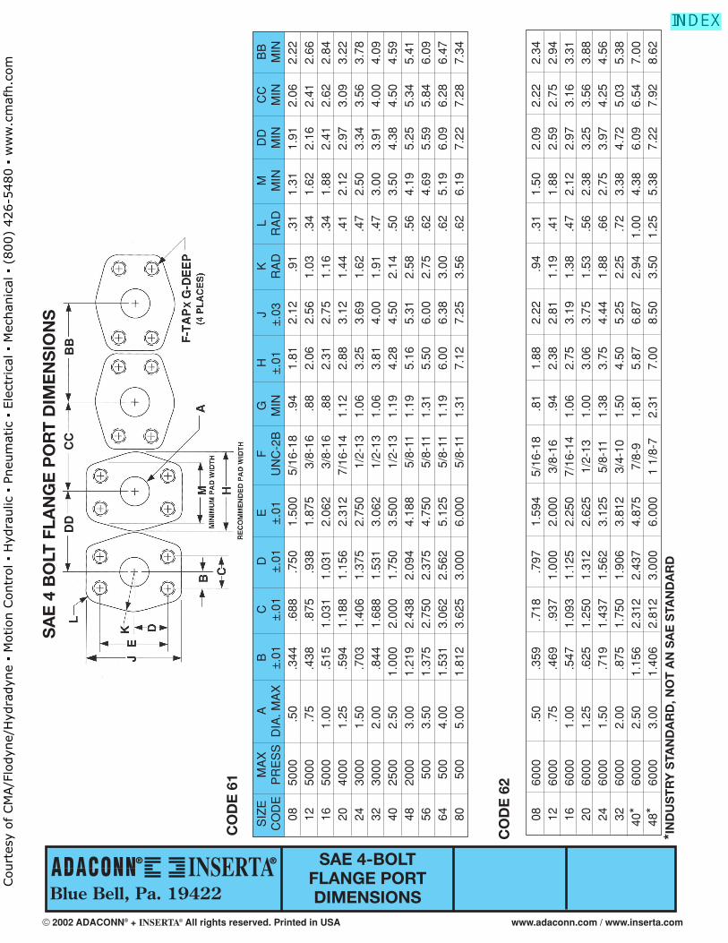
Blue Bell, Pa. 19422
SAE 4-BOLT FLANGE PORTDIMENSIONS
® ®
SA
E 4
BO
LT F
LAN
GE
PO
RT
DIM
EN
SIO
NS
CO
DE
61
S
IZE
M
AX
A
B
C
D
E
F
G
H
J
K
L M
D
D
CC
B
B
CO
DE
P
RE
SS
D
IA. M
AX
±
.01
±.0
1 ±
.01
±.0
1 U
NC
-2B
M
IN
±.0
1 ±
.03
RA
D
RA
D
MIN
M
IN
MIN
M
IN
08
5000
.5
0 .3
44
.688
.7
50
1.50
0 5/
16-1
8 .9
4 1.
81
2.12
.9
1 .3
1 1.
31
1.91
2.
06
2.22
12
50
00
.75
.438
.8
75
.938
1.
875
3/8-
16
.88
2.06
2.
56
1.03
.3
4 1.
62
2.16
2.
41
2.66
16
50
00
1.00
.5
15
1.03
1 1.
031
2.06
2 3/
8-16
.8
8 2.
31
2.75
1.
16
.34
1.88
2.
41
2.62
2.
84
20
4000
1.
25
.594
1.
188
1.15
6 2.
312
7/16
-14
1.12
2.
88
3.12
1.
44
.41
2.12
2.
97
3.09
3.
22
24
3000
1.
50
.703
1.
406
1.37
5 2.
750
1/2-
13
1.06
3.
25
3.69
1.
62
.47
2.50
3.
34
3.56
3.
78
32
3000
2.
00
.844
1.
688
1.53
1 3.
062
1/2-
13
1.06
3.
81
4.00
1.
91
.47
3.00
3.
91
4.00
4.
09
40
2500
2.
50
1.00
0 2.
000
1.75
0 3.
500
1/2-
13
1.19
4.
28
4.50
2.
14
.50
3.50
4.
38
4.50
4.
59
48
2000
3.
00
1.21
9 2.
438
2.09
4 4.
188
5/8-
11
1.19
5.
16
5.31
2.
58
.56
4.19
5.
25
5.34
5.
41
56
500
3.50
1.
375
2.75
0 2.
375
4.75
0 5/
8-11
1.
31
5.50
6.
00
2.75
.6
2 4.
69
5.59
5.
84
6.09
64
50
0 4.
00
1.53
1 3.
062
2.56
2 5.
125
5/8-
11
1.19
6.
00
6.38
3.
00
.62
5.19
6.
09
6.28
6.
47
80
500
5.00
1.
812
3.62
5 3.
000
6.00
0 5/
8-11
1.
31
7.12
7.
25
3.56
.6
2 6.
19
7.22
7.
28
7.34
CO
DE
62
08
60
00
.50
.359
.7
18
.797
1.
594
5/16
-18
.81
1.88
2.
22
.94
.31
1.50
2.
09
2.22
2.
34
12
6000
.7
5 .4
69
.937
1.
000
2.00
0 3/
8-16
.9
4 2.
38
2.81
1.
19
.41
1.88
2.
59
2.75
2.
94
16
6000
1.
00
.547
1.
093
1.12
5 2.
250
7/16
-14
1.06
2.
75
3.19
1.
38
.47
2.12
2.
97
3.16
3.
31
20
6000
1.
25
.625
1.
250
1.31
2 2.
625
1/2-
13
1.00
3.
06
3.75
1.
53
.56
2.38
3.
25
3.56
3.
88
24
6000
1.
50
.719
1.
437
1.56
2 3.
125
5/8-
11
1.38
3.
75
4.44
1.
88
.66
2.75
3.
97
4.25
4.
56
32
6000
2.
00
.875
1.
750
1.90
6 3.
812
3/4-
10
1.50
4.
50
5.25
2.
25
.72
3.38
4.
72
5.03
5.
38
40*
6000
2.
50
1.15
6 2.
312
2.43
7 4.
875
7/8-
9 1.
81
5.87
6.
87
2.94
1.
00
4.38
6.
09
6.54
7.
00
48*
6000
3.
00
1.40
6 2.
812
3.00
0 6.
000
1 1/
8-7
2.31
7.
00
8.50
3.
50
1.25
5.
38
7.22
7.
92
8.62
*IN
DU
ST
RY
STA
ND
AR
D, N
OT
AN
SA
E S
TAN
DA
RD
BB
CC
DD
© 2002 ADACONN® + INSERTA® All rights reserved. Printed in USA www.adaconn.com / www.inserta.com
Court
esy
of CM
A/F
lodyn
e/H
ydra
dyn
e ▪
Motion C
ontr
ol ▪
Hyd
raulic
▪ P
neu
mat
ic ▪
Ele
ctrica
l ▪
Mec
han
ical
▪ (
800)
426-5
480 ▪
ww
w.c
maf
h.c
om
SAE STRAIGHTTHREAD PORTDIMENSIONS
SAE STRAIGHT THREAD PORTDIMENSIONS
NOMINAL C F SIZE TUBE THREAD A B* +.015 D E +.005 G H CODE SIZE SIZE MIN MIN –.000 MIN MAX –.000 MIN ±1°
– 2 1/8 5/16-24 .062 .390 .074 .468 .062 .358 .672 12
– 3 3/16 3/8-24 .125 .390 .074 .468 .062 .421 .750 12
– 4 1/4 7/16-20 .172 .454 .093 .547 .062 .487 .828 12
– 5 5/16 1/2-20 .234 .454 .093 .547 .062 .550 .906 12
– 6 3/8 9/16-18 .297 .500 .097 .609 .062 .616 .969 12
– 8 1/2 3/4-16 .391 .562 .100 .688 .094 .811 1.188 15
– 10 5/8 7/8-14 .484 .656 .100 .781 .094 .942 1.344 15
– 12 3/4 1 1/16-12 .609 .750 .130 .906 .094 1.148 1.625 15
– 14 7/8 1 3/16-12 .719 .750 .130 .906 .094 1.273 1.765 15
– 16 1 1 5/16-12 .844 .750 .130 .906 .125 1.398 1.910 15
– 20 1 1/4 1 5/8-12 1.078 .750 .132 .906 .125 1.713 2.270 15
– 24 1 1/2 1 7/8-12 1.312 .750 .132 .906 .125 1.962 2.560 15
– 32 2 2 1/2-12 1.781 .750 .132 .906 .125 2.587 3.480 15
– 40 ** 2 1/2 3-12 2.344 .750 .132 1.250 .094 3.088 3.875 15
– 48 ** 3 3 1/2-12 2.844 .750 .132 1.250 .094 3.588 4.438 15
FOR BEST RESULTS USE A FORM TOOL TO MACHINE CAVITY
**REQUIRES USING A BOTTOM TAP**NOT AN SAE STANDARD. INSERTATM PRODUCTS, I STANDARD.
SAE information is provided as an aid to designers. For com-plete specifi cations refer to SAE Standards J1926 for straight thread ports and J518 JUN93 for 4-Bolt fl ange ports.
® ®
® ®
Blue Bell, Pa. 19422
® ®
© 2002 ADACONN® + INSERTA® All rights reserved. Printed in USA www.adaconn.com / www.inserta.com
Court
esy
of CM
A/F
lodyn
e/H
ydra
dyn
e ▪
Motion C
ontr
ol ▪
Hyd
raulic
▪ P
neu
mat
ic ▪
Ele
ctrica
l ▪
Mec
han
ical
▪ (
800)
426-5
480 ▪
ww
w.c
maf
h.c
om
ADACONN® INSERTA PRODUCTS, INC.LIMITED WARRANTY LIMITED WARRANTY
ADACONN® and INSERTA® warrants that its products are free from defects in material or workmanship for a period of 18 months from the date of our shipment. O-Rings and seals are specifically exempted from this warranty. THIS WARRANTY COMPRISES THE SOLE AND ENTIRE WARRANTY. THERE IS NO OTHER WARRANTY, GUARANTEE, OR REPRESENTATION OF ANY KIND WHATSOEVER. ALL OTHER WARRANTIES, INCLUDING BUT NOT LIMITED TO, MERCHANTABILITY AND FITNESS FOR PURPOSE,WHETHER EXPRESS, IMPLIED, OR ARISING BY OPERATION OF LAW, TRADE USAGE, OR COURSEOF DEALING ARE HEREBY DISCLAIMED. NOTWITHSTANDING THE FOREGOING, THERE ARE NO WARRANTIES WHATSOEVER ON ITEMS BUILT OR ACQUIRED WHOLLY OR PARTIALLY, TO BUYER’SDESIGNS OR SPECIFICATIONS.
Written permission for any warranty returns must be obtained from ADACONN® and/or INSERTA® prior to shipment. Ship all warranty returns Freight Prepaid and include a complete explanation of the defects and circumstances.
ADACONN® INSERTA PRODUCTS, INC.LIMITATION OF REMEDY LIMITATION OF REMEDY
ADACONN® and INSERTA® LIABILITY ARISING FROM OR IN ANY WAY CONNECTED WITH ITEMS SOLDSHALL BE LIMITED EXCLUSIVELY TO REPAIR OR REPLACEMENT OF THE ITEMS SOLD OR REFUNDOF THE PURCHASE PRICE PAID BY BUYER, AT SELLERS SOLE OPTION. IN NO EVENT SHALL SELLERBE LIABLE FOR ANY INCIDENTAL, CONSEQUENTIAL OR SPECIAL DAMAGES OF ANY KIND ORNATURE WHATSOEVER, INCLUDING BUT NOT LIMITED TO LOST PROFITS ARISING FROM OR IN ANY WAY CONNECTED WITH THE ITEMS SOLD, WHETHER ALLEGED TO ARISE FROM BREACHOF CONTRACT, EXPRESS OR IMPLIED WARRANTY, OR IN TORT, INCLUDING WITHOUT LIMITATION,NEGLIGENCE, FAILURE TO WARN OR STRICT LIABILITY.
! WARNING
FAILURE OR IMPROPER SELECTION OR IMPROPER USE OF THE PRODUCTS AND/OR SYSTEMS DESCRIBEDHEREIN OR RELATED ITEMS CAN CAUSE DEATH, PERSONAL INJURY AND PROPERTY DAMAGE.
This document and other information from ADACONN® and INSERTA® and authorized distributors provide product and/or system options for further investigation by users having technical expertise. It is important that youanalyze all aspects of your application and review the information concerning the product or system in the current product catalog. Due to the variety of operating conditions and applications for these products or systems, the user, through its ownanalysis and testing, is solely responsible for making the final selection of the products and systems and assuring that all performance, safety, and warning requirements of the application are met.
The product described herein, including without limitation, product features, specifications, designs, availability andpricing, are subject to change by ADACONN® and INSERTA® at any time without notice.
ADACONN® INSERTA PRODUCTS, INC.538 Township Line Rd 538 Township Line Rd
Blue Bell PA 19422 Blue Bell PA 19422(215) 643-1900 (215) 643-0192
Fax (215) 643-4017 Fax (215) 643-4017www.adaconn.com www.inserta.com
email: [email protected] email: [email protected]
® ®
© 2002 ADACONN® + INSERTA® All rights reserved. Printed in USA www.adaconn.com / www.inserta.com
Court
esy
of CM
A/F
lodyn
e/H
ydra
dyn
e ▪
Motion C
ontr
ol ▪
Hyd
raulic
▪ P
neu
mat
ic ▪
Ele
ctrica
l ▪
Mec
han
ical
▪ (
800)
426-5
480 ▪
ww
w.c
maf
h.c
om
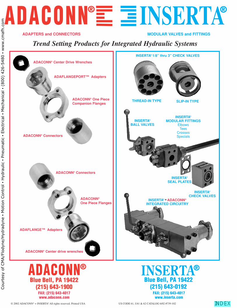
Blue Bell, PA 19422(215) 643-0192
Blue Bell, PA 19422(215) 643-1900
® ®
© 2002 ADACONN® + INSERTA® All rights reserved. Printed USA US CODE 61, U61 & 62 CATALOG 6/02 #739-102
INSERTA® + ADACONN®
INTEGRATED CIRCUITRY
INSERTA®
MODULAR FITTINGSElbowsTees
CrossesSpecials
INSERTA®
CHECK VALVES
INSERTA®
SEAL PLATES
INSERTA®
BALL VALVES
THREAD-IN TYPE
ADACONN® Center Drive Wrenches
SLIP-IN TYPE
INSERTA® 1/8” thru 3” CHECK VALVES
Trend Setting Products for Integrated Hydraulic Systems
ADAFLANGEPORT™ Adapters
ADAFLANGE™ Adapters
ADACONN® One Piece Companion Flanges
ADACONN® Connectors
ADACONN® Center drive wrenches
ADACONN® Connectors
ADACONN®
One Piece Flanges
® ®
ADAPTERS and CONNECTORS MODULAR VALVES and FITTINGS
FAX: (215) 643-4017www.adaconn.com
FAX: (215) 643-4017www.inserta.com
Court
esy
of CM
A/F
lodyn
e/H
ydra
dyn
e ▪
Motion C
ontr
ol ▪
Hyd
raulic
▪ P
neu
mat
ic ▪
Ele
ctrica
l ▪
Mec
han
ical
▪ (
800)
426-5
480 ▪
ww
w.c
maf
h.c
om