Embed Size (px)
Citation preview
University of Arkansas, FayettevilleScholarWorks@UARK
Theses and Dissertations
7-2015
Adaptive Controller Using Runtime PartialHardware Reconfiguration for Unmanned AerialVehicles (UAVs)Nikhil ThomasUniversity of Arkansas, Fayetteville
Follow this and additional works at: http://scholarworks.uark.edu/etd
Part of the Other Computer Engineering Commons
This Thesis is brought to you for free and open access by ScholarWorks@UARK. It has been accepted for inclusion in Theses and Dissertations by anauthorized administrator of ScholarWorks@UARK. For more information, please contact [email protected], [email protected].
Recommended CitationThomas, Nikhil, "Adaptive Controller Using Runtime Partial Hardware Reconfiguration for Unmanned Aerial Vehicles (UAVs)"(2015). Theses and Dissertations. 1254.http://scholarworks.uark.edu/etd/1254
Adaptive Controller Using Runtime Partial Hardware Reconfiguration for
Unmanned Aerial Vehicles (UAVs)
A thesis submitted in partial fulfillment
of the requirements for the degree of
Master of Science in Computer Engineering
by
Nikhil Thomas
Cochin University of Science and Technology
Bachelor of Technology in Computer Science and Computer Engineering, 2009
University of Arkansas
Master of Science in Microelectronics-Photonics, 2013
July 2015
University of Arkansas
This thesis is approved for the recommendation of the Graduate Council.
_____________________________________
Dr. Christophe Bobda
Thesis Director
_____________________________________ _____________________________________
Dr. David Andrews Dr. James Parkerson
Committee Member Committee Member
_____________________________________
Dr. Dharmendra Saraswat
Co-Advisor
Abstract
The goal of this thesis is to explore the feasibility of a multirotor controller system which
can dynamically change the arm configuration of a multirotor. Currently most of the multirotor
systems have to be powered down, rewired, and programmed with new firmware, to configure
how many arms/motors they use to fly. The focus of our effort is to develop a Field
Programmable Gate Array (FPGA) based hardware/software controller which uses dynamic
partial hardware reconfiguration to switch the arm/motor configuration of a multirotor during
operation. We believe that this will make a multirotor more fault tolerant and adaptive. This
thesis explains the design and development of a simple multirotor reconfiguration system which
can start with a six arm configuration and switch to a four arm configuration or a three arm
configuration and back.
The design and implementation of the hardware and software on a Xilinx Zynq System
on chip prototyping board (ZedBoard) is explained in this thesis. The system is used for single
axis balancing of the multirotor. Observations from the experiments, limitations of the current
design, and potential future developments are also listed in this thesis.

Acknowledgement
I express my gratitude to Dr. Christophe Bobda and Dr. Dharmendra Saraswat for
trusting me. I thank you both for giving me this opportunity to work on the projects you assigned
me. My experience as a graduate student has helped develop myself as a skilled engineer and as
a disciplined person. Thank you for pushing me hard. Thank you for making me realize that I can
work harder than what I used to believe is my limit.
I thank my committee members Dr. David Andrews and Dr. James Parkerson for their
support in my work for this thesis project. I will always be grateful to everyone who has helped
me learn and improve my skills.
I thank all my colleagues who always helped me progress in my work. I thank Ben
Hancock for giving me a strong foundation. I appreciate your patience and your time. I thank
Luca Bochi Saldanha, Franck Yonga, and Michael Mefenza for motivating me to work hard and
for appreciating my efforts. I also thank Danny Thepvongsa and Andrew Felder for their effort in
accelerating the progress of this project.
I thank my parents for giving me good education and loving me unconditionally. I also
thank my brother for always being there for me.
And I thank my partner Seena Solomon, for making me smile, making me hopeful,
making me pray and motivating me to be good a person.

Dedication
I dedicate this work to God, the master of all creativity.
Table of Contents
Chapter I Introduction ..................................................................................................................... 1
I.1 Overview ................................................................................................................................ 1
I.2 Background and Motivation .................................................................................................. 3
I.3 Hypothesis.............................................................................................................................. 4
I.4 Scope of this Thesis ............................................................................................................... 7
I.5 Summary of Chapters ............................................................................................................ 9
Chapter II Materials and Methods ................................................................................................ 10
II.1 Overview ............................................................................................................................ 10
II.2 Xilinx Zynq System on Chip .............................................................................................. 10
II.3 ZedBoard ............................................................................................................................ 11
II.4 Dynamic Partial Hardware Reconfiguration ...................................................................... 13
II.5 Hardware Components ....................................................................................................... 14
II.5.1 Multirotor ..................................................................................................................... 14
II.5.2 Gyro Sensor ................................................................................................................. 15
II.5.3 Voltage and Current Sensor ......................................................................................... 16
Chapter III Design and Implementation ....................................................................................... 17
III.1 Design Overview ............................................................................................................... 17
III.2 Multirotor Configurations Considered in this Project ....................................................... 19
III.2.1 Six Motor Configuration (1, 2, 3, 4, 5, 6) ................................................................... 19
III.2.2 Four Motor Configuration (1, 3, 4, 6)......................................................................... 20
III.2.3 Four Motor Configurations (1, 2, 4, 5) ....................................................................... 22
III.2.4 Four Motor Configurations (2, 3, 5, 6) ....................................................................... 22
III.2.5 Three Motor Configurations (1, 3, 5) ......................................................................... 23
III.2.6 Three Motor Configurations (2, 4, 6) ......................................................................... 24
III.3 Control Module Switching Logic ...................................................................................... 25
III.4 Hardware Design ............................................................................................................... 29
III.4.1 Design0: Simple Design without Partial Hardware Reconfiguration ......................... 29
III.4.2 Design1: Hardware Design with a Reconfigurable Partition ..................................... 30
III.4.3 Design2: Prototype with PID and Gyro sensor .......................................................... 31
III.4.4 Design of Individual Control Modules ....................................................................... 33
III.4.5 Design of PWM Generator ......................................................................................... 34

III.5 Software Design ................................................................................................................ 36
III.5.1 Input/output ................................................................................................................ 37
III.5.2 PID Control Algorithm ............................................................................................... 37
III.5.3 Managing Partial Hardware Reconfiguration ............................................................. 37
Chapter IV Experiments and Results ............................................................................................ 39
IV.1 Overview ........................................................................................................................... 39
IV.2 Experimental Setup ........................................................................................................... 39
IV.3 Experiment0: Simple Hardware Design ........................................................................... 40
IV.4 Experiment1: Hardware Design with a Reconfigurable Partition .................................... 41
IV.5 Experiment2: Prototype with PID control ........................................................................ 43
IV.6 Observations...................................................................................................................... 44
IV.6.1 PWM vs Current ......................................................................................................... 44
IV.6.2 Multirotor Configurations vs Current......................................................................... 45
Chapter V Conclusion and Future Work ...................................................................................... 47
V.1 Conclusion .......................................................................................................................... 47
V.2 Potential Applications ........................................................................................................ 49
V.3 Future work ........................................................................................................................ 51
V.3.1 Multiplexed Dual Reconfigurable Partitions ............................................................... 51
V.3.2 User Input from a Radio/Bluetooth Controller ............................................................ 52
V.3.3 Mathematical Modeling of Multirotor ......................................................................... 52
Bibliography ................................................................................................................................. 53
List of Figures
Figure I.1: Expected variation in load carrying capacity and duration of flight of different
multirotor flight configurations when the motors, propellers and the battery is of the same type . 4
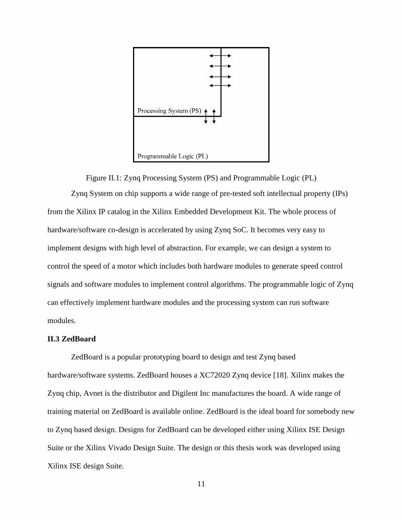
Figure II.1: Zynq Processing System (PS) and Programmable Logic (PL) .................................. 11
Figure II.2: ZedBoard (Photo taken by author) ............................................................................ 12
Figure II.3: Dynamic partial hardware reconfiguration ................................................................ 13
Figure II.4: Roll, pitch, and yaw of a multirotor ........................................................................... 15
Figure II.5: Digilent PmodGYRO 3-Axis digital gyroscope (Photo taken by author) ................. 16
Figure II.6: Sparkfun AttoPilot voltage and current sensor (Photo taken by author) ................... 16
Figure III.1: Design overview ....................................................................................................... 17
Figure III.2: Six motor configuration ............................................................................................ 19
Figure III.3: Four motor configuration (1, 3, 4, 6) ........................................................................ 20
Figure III.4: Torque distribution ................................................................................................... 21
Figure III.5: Four motor configuration (1, 2, 4, 5) ........................................................................ 22
Figure III.6: Four motor configuration 2, 3, 5, 6) ......................................................................... 22
Figure III.7: Three motor configuration (1, 3, 5) .......................................................................... 23
Figure III.8: Three motor configuration (2, 4, 6) .......................................................................... 24
Figure III.9: A valid configuration (left), an invalid configuration (right) ................................... 27
Figure III.10: Hardware design without partial reconfiguration. Flat design: all seven
configurations are connected in through a 7-to-1 multiplexer to the output................................. 29
Figure III.11: Hardware design with a reconfigurable partition, seven different configuration are
implemented as partial bit streams ................................................................................................ 30
Figure III.12: Gyro sensor and timer added to hardware design which already has a
reconfigurable partition ................................................................................................................. 31
Figure III.13: Structure of a reconfigurable control module ‘four motor 1‘(1, 3, 4, 6) ................ 34
Figure III.14: PWM generator design ........................................................................................... 35
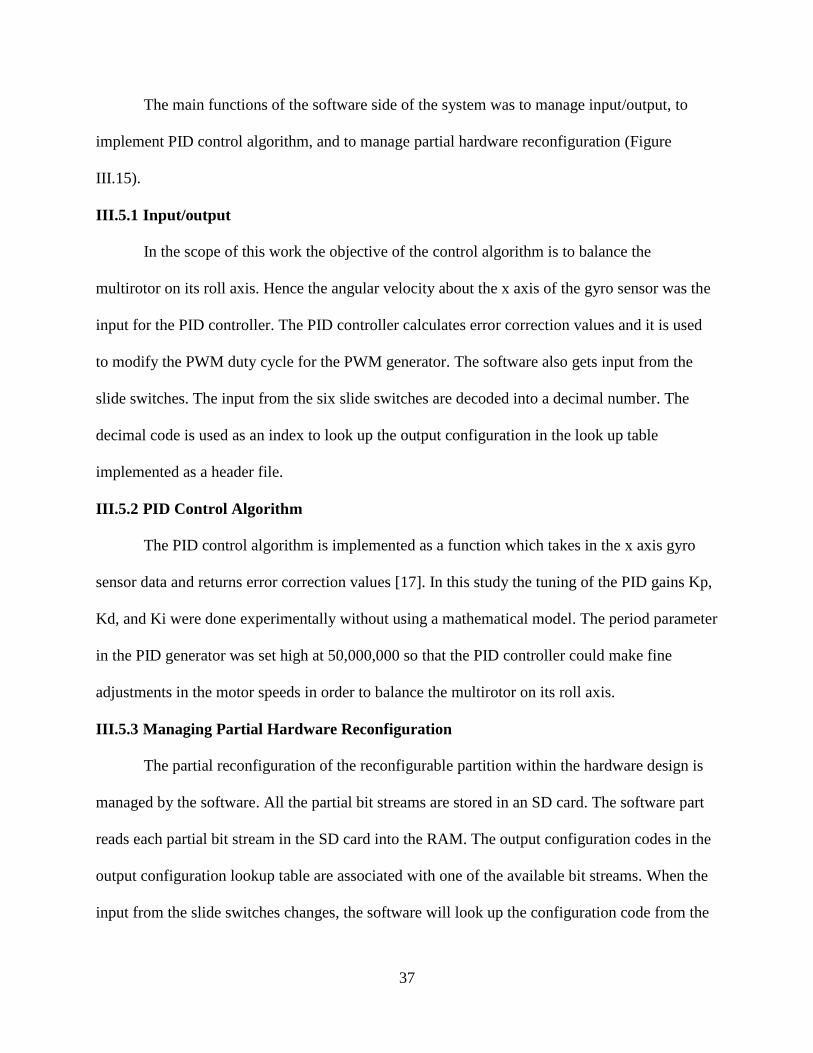
Figure III.15: Software design ...................................................................................................... 36
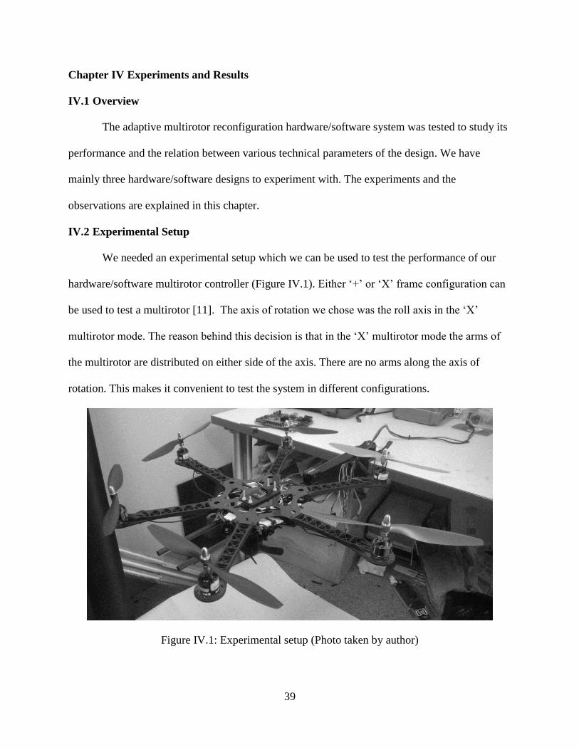
Figure IV.1: Experimental setup (Photo taken by author) ............................................................ 39
Figure IV.2: PWM duty vs Current (at different values of Voltage) ............................................ 45
Figure IV.3: Multirotor configuration vs Current (at different values of Voltage) ...................... 46
List of Tables
Table III.1: Multirotor control switching logic input and output configurations ......................... 26
Table III.2: Mapping of input switch values to a multirotor arm configuration ........................... 28
Table III.3: PWM minimum duty and maximum duty for different period values ...................... 36
Table IV.1: Implemented FPGA resources utilization of Design 0 .............................................. 41
Table IV.2: Implemented FPGA resources utilization of Design 1 .............................................. 42
Table IV.3: Implemented FPGA resources utilization of Design 2 .............................................. 43
Table IV.4: Current drawn at different PWM duty (higher the PWM higher the motor speed) .. 44
Table IV.5: Current drawn for different configurations (more motor draw more current) .......... 45
Table V.1: Theoretical estimation of operation time .................................................................... 49
Table V.2: Hypothetical application: table showing operation duration for different
configurations for a given load ..................................................................................................... 50
1
Chapter I Introduction
I.1 Overview
A multirotor, or a multicopter, is an aircraft which uses more than one motorized
propeller to propel itself. A multirotor is aerodynamically unstable, which means it needs an
intelligent controller to maintain a stable state while in operation. Unlike a fixed wing aircraft a
multirotor cannot glide and land when the controller malfunctions or when the propulsion goes
offline. The main advantage of multirotors over fixed wing aircraft is their ability to vertically
takeoff and land (VTOL). Hence multirotors do not need a runway for takeoff or landing,
making them ideal for geographically challenging areas. Nowadays, multirotors are used in
various areas such as aerial photography, geospatial studies, etc [1]. Multirotor technology
developed so fast from being a toy to a highly useful tool which has applications in both
scientific research and entertainment.
The advancements in components and materials has made multirotor more efficient.
Brushless motors and Lithium Polymer (LiPo) batteries are key factors in the advancement of
multirotor technology [2, 3]. Development in multirotor control software equipped with features
like autonomous navigation, has made multirotors more intelligent. Cutting edge research is
taking place in design, development, and applications of multirotors. Various onboard image
processing technologies help multirotors collect and process visual inputs [4, 5]. On the one
hand, tiny multirotors can communicate with each other and collaborate in performing a task [6].
On the other, heavy duty multirotors are being developed to retrieve and deliver packages [7].
Multirotors which can be used for human transportation vehicles are also in development [8, 9].
A variety of excellent off-the-shelf flight controller boards are now available. The flight
control boards are mass produced hardware and the opportunity to customize and develop the
2
hardware is less compared to customizability in flight control software. Off-the-shelf flight
control boards abstract their internal design behind their hardware abstraction layers (HAL).
Hence it becomes very difficult for an interested user to learn multirotor techniques implemented
beneath the HAL. An aspect of multirotor technology which is not explored a lot is the
customization of flight control hardware circuit.
We believe that the rapidly developing computer hardware technology Field
Programmable Gate Arrays (FPGAs) can be used to address this problem. The goals of this
thesis are
To experiment with FPGA based multirotor control hardware
To make adaptive multirotor controllers using runtime partial hardware reconfiguration
of FPGAs technology
To investigate advantages of using a FPGA based multirotor controller
The main advantage of FPGAs is that they are programmable hardware [10]. That is, a
FPGA is a fabric of logic units which can be used to rapidly prototype hardware designs
developed in Hardware Description Languages (HDL) such as VHDL, Verilog, etc. Efficient
hardware can be developed using FPGA technology. The possibility to customize the hardware is
endless. The most satisfying aspect in the development of FPGA based multirotor controller is
the combined hardware/software experience. The developer gets complete access to all hardware
and software features of the system. However, FPGA based flight controllers are in their initial
stages of development. There is a lot more work to be done in this direction to make top level
software features of off-the-shelf multirotor control boards available with FPGA based systems.
3
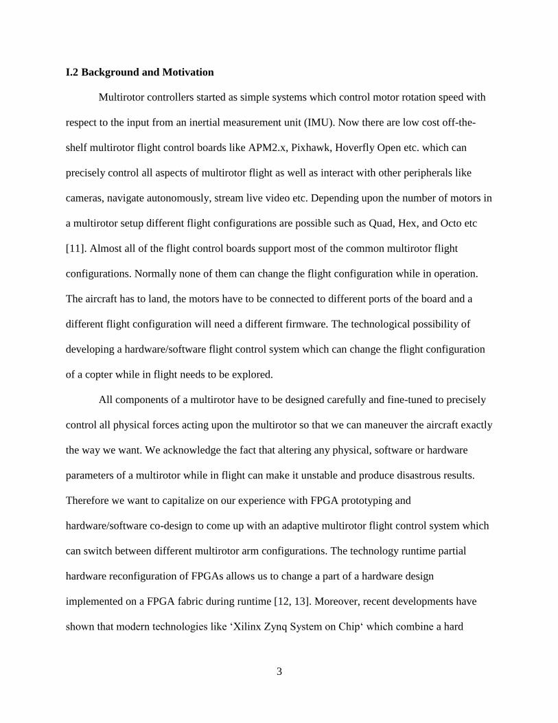
I.2 Background and Motivation
Multirotor controllers started as simple systems which control motor rotation speed with
respect to the input from an inertial measurement unit (IMU). Now there are low cost off-the-
shelf multirotor flight control boards like APM2.x, Pixhawk, Hoverfly Open etc. which can
precisely control all aspects of multirotor flight as well as interact with other peripherals like
cameras, navigate autonomously, stream live video etc. Depending upon the number of motors in
a multirotor setup different flight configurations are possible such as Quad, Hex, and Octo etc
[11]. Almost all of the flight control boards support most of the common multirotor flight
configurations. Normally none of them can change the flight configuration while in operation.
The aircraft has to land, the motors have to be connected to different ports of the board and a
different flight configuration will need a different firmware. The technological possibility of
developing a hardware/software flight control system which can change the flight configuration
of a copter while in flight needs to be explored.
All components of a multirotor have to be designed carefully and fine-tuned to precisely
control all physical forces acting upon the multirotor so that we can maneuver the aircraft exactly
the way we want. We acknowledge the fact that altering any physical, software or hardware
parameters of a multirotor while in flight can make it unstable and produce disastrous results.
Therefore we want to capitalize on our experience with FPGA prototyping and
hardware/software co-design to come up with an adaptive multirotor flight control system which
can switch between different multirotor arm configurations. The technology runtime partial
hardware reconfiguration of FPGAs allows us to change a part of a hardware design
implemented on a FPGA fabric during runtime [12, 13]. Moreover, recent developments have
shown that modern technologies like ‘Xilinx Zynq System on Chip‘ which combine a hard
4
processing element with a FPGA fabric has immense potential in the domain of multirotor flight
control [4].
I.3 Hypothesis
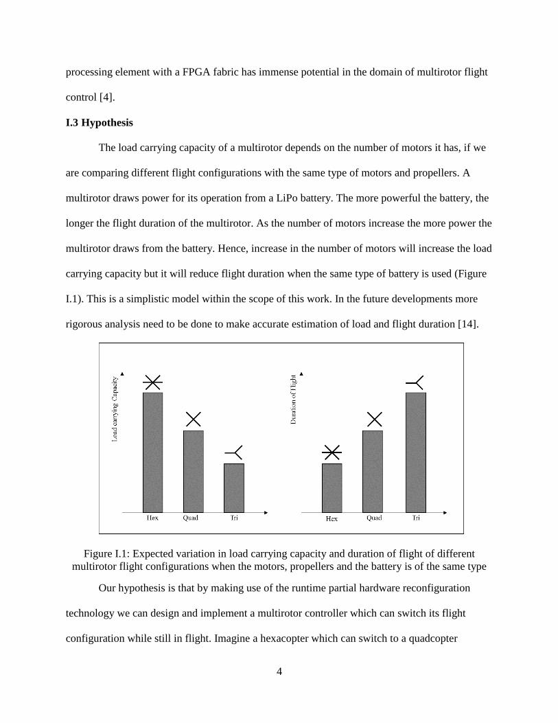
The load carrying capacity of a multirotor depends on the number of motors it has, if we
are comparing different flight configurations with the same type of motors and propellers. A
multirotor draws power for its operation from a LiPo battery. The more powerful the battery, the
longer the flight duration of the multirotor. As the number of motors increase the more power the
multirotor draws from the battery. Hence, increase in the number of motors will increase the load
carrying capacity but it will reduce flight duration when the same type of battery is used (Figure
I.1). This is a simplistic model within the scope of this work. In the future developments more
rigorous analysis need to be done to make accurate estimation of load and flight duration [14].
Figure I.1: Expected variation in load carrying capacity and duration of flight of different
multirotor flight configurations when the motors, propellers and the battery is of the same type
Our hypothesis is that by making use of the runtime partial hardware reconfiguration
technology we can design and implement a multirotor controller which can switch its flight
configuration while still in flight. Imagine a hexacopter which can switch to a quadcopter
5
configuration and then to a tricopter configuration as needed. We understand the challenges with
respect to balancing the physical forces on a multirotor like angular momentum. Conventionally,
the total angular momentum of a multirotor is balanced by alternating the propeller spin direction
(clock wise and counter clockwise) [11]. We intend to use the alternate configurations which use
two motors per arm of a multirotor in the future. The upward facing motors with clockwise
propellers can have clockwise spin and the downward facing motors with counter clockwise
propellers can have counter clockwise spin. These configurations should make the net angular
momentum of the two motors in an arm cancel out each other. Therefore if we use the
configurations tricopter with six motors (Y6), quadcopter with eight motors (X8) and a
hexacopter with twelve motors it should be possible to balance the net angular momentum even
after dynamically switching the configurations. The double motor configurations are not
implemented in this work. They needed to be tested in future developments.
Our goal is to explore the challenges in developing multirotor controllers which can
accommodate the flexibility to choose a flight configuration as and when the need arises. For
example a hexacopter with an adaptable flight controller can switch between different flight
configurations. It can use all motors to configure itself as a hexacopter. There are three ‘four
motor’ configurations available depending upon the motors being used. It also has two flight
configurations where three motors are used to attain stable flight. We think this feature has a
wide range of applications. The potential advantages of adaptive flight configuration can be
summarized into two categories:
1. Fault Tolerance: If a motor in the proposed multirotor setup malfunctions, it can switch
into a configuration which does not use that motor and still maintain stable flight. It can
also recruit all motors to attain steady flight in adverse environmental conditions like
6
strong winds. That is if strong winds are causing disturbances while the multirotor is
flying with a three arm configuration, it can switch itself into a configuration that uses
four or six arms. Hence a multirotor which can change its flight configuration during
operation will be more fault tolerant.
2. Optimized Performance: The required thrust, sturdiness of flight, flight duration, and
speed can vary depending upon the factors such as load, environmental condition, time
and power constraints etc. A multirotor with runtime arm configuration adaptivity will
give the user the ability to control power utilization and flight duration. Imagine a
multirotor used for delivering a relatively heavy package. The multirotor (twelve motors
in hex configuration) might need to use all of its motors to carry the load to its
destination. However, it might need much less load carrying capacity to fly back to its
base. An operator can choose the flight configurations depending upon the nature of the
flight mission. This scenario has a lot of relevance as studies are being done on the use of
aerial vehicles to deliver packages [7, 15].
In addition, we firmly believe that FPGAs have a major role in unifying the software
hardware design process. In any computer system the limit for the performance of software is the
underlying hardware. Use of FPGAs can push this limit and make system design process a
simultaneous development of hardware and software components. In other words, FPGA
technology offers more transparency in the hardware domain, which in turn helps us write better
software with functions abstracted in both hardware and software modules.
Advanced features like runtime partial hardware reconfiguration can lead to more
powerful control boards for multirotors. Runtime partial hardware reconfiguration adds
flexibility and customizability on the same amount of FPGA real estate. Functions like image
7
processing for feature/object detection, telecommunication etc. can be designed as reconfigurable
partitions which will lead to more powerful multirotor flight control systems. Therefore we
believe that there is high potential in this research direction where FPGAs or System on Chip
technology is used as a platform which not only controls multirotor flight but also supports more
high level applications of multirotors.
I.4 Scope of this Thesis
This thesis is our first step in the direction of developing adaptive multirotor controller
which supports adaptive flight configurations. Our goal is to design, implement, and study the
performance of adaptive multirotor configurations with respect to one rotational degree of
freedom, the roll (angle measure on x axis with respect to center of gravity of multirotor) [16].
We have a hexacopter multirotor setup which can pivot along its roll axis. The features of the
multirotor and the experimental setup will be discussed in the coming chapters. We have
designed a hardware software system which has a dynamically reconfigurable hardware module
which can be reconfigured with modules associated with different flight configurations.
We are not trying to develop a new control algorithm for multirotor flight. Hence this
thesis will not discuss mathematical modeling of multirotors. We are using a Proportional
Integral Derivative (PID) control algorithm to balance the multirotor on its roll axis [17]. We
have implemented the PID algorithm in the software side of the system. That is the PID
algorithm runs on top of the hardware platform consisting of the Zynq processing system (Cortex
A9 processor) and our custom hardware (which has a reconfigurable hardware partition).
Currently the functions of our custom hardware are reading input from a gyro sensor which
measures angular velocity of the multirotor and producing pulse width modulated (PWM) signals
8
to control the motor speeds. The reconfigurable hardware partition distributes the PWM signals
to the motors depending on the current configuration and control signals from the software
The Xilinx Zynq System on Chip prototyping board ‘the ZedBoard’ is used to test our
design. Zynq has a processing system which consists of two Cortex A9 processors and
programmable logic which is the FPGA fabric. Our hardware is designed in VHDL using
hardware prototyping tools from Xilinx. The software side of our system is implemented in C.
The software communicates with the custom hardware through memory mapped registers.
We used a commercially available hexacopter as our multirotor (XAircraft DIY Hexa) to
test our design. The hexacopter came with a third party flight control board (APM 2.5). The
flight control board was powerful and had many features. However, we wanted to use our FPGA
based multirotor controller design. We connected the electronic speed controllers of the
hexacopter to our hardware/software adaptive control system directly. We used a gyro sensor
peripheral module from Digilent Inc to measure the angular velocity of the multirotor in the three
axis. We started with a simple design then iteratively modified it. The development of this base
system went through three design iterations.
1. Adaptive configuration controller without partial hardware reconfiguration: This design
consists of all the different configuration control modules built into one system.
2. Adaptive configuration controller with partial hardware reconfiguration: This design
incorporates runtime partial hardware reconfiguration technology
3. Adaptive configuration controller with partial hardware reconfiguration working with
PID control in software: A gyro sensor is added to the hardware. PID control algorithm is
implemented in software. The hardware/software system is used to balance the multirotor
on its roll axis.
9
The adaptive controller system was tested to find out the variation in power requirement
for different multirotor configurations. The design with partial hardware reconfiguration and the
model without partial hardware reconfiguration were compared.
In short this thesis demonstrates an innovative multirotor controller with adaptive motor
configuration which is implemented using runtime partial hardware reconfiguration technique on
Xilinx Zynq System on Chip.
I.5 Summary of Chapters
Chapter II Materials and Methods: This chapter explains different concepts and technology
associated with this project. The key topics explained in the chapter are Partial Hardware
Reconfiguration Technology and multirotor basics.
Chapter III Design and Implementation: This chapter explains the overall design process of our
adaptive multirotor controller. Different blocks of the design are explained.
Chapter IV Experiments and Results: This chapter presents the experimental data and
observations.
Chapter V Conclusion and Future Work: This chapter is about conclusions drawn from the
experiments. It also shares recommendations and objectives for future work.
10
Chapter II Materials and Methods
II.1 Overview
The adaptive multirotor controller is designed with Xilinx Zynq as the target device.
Field Programmable Gate Arrays (FPGA) makes hardware prototyping cheaper and faster
compared to design and fabrication of Application Specific Integrated Circuit (ASIC) Chips.
Xilinx Zynq supports runtime hardware partial reconfiguration. This feature is the key
technology driving this project. The multirotor controller uses runtime partial hardware
reconfiguration to switch between different multirotor arm configurations. The Zynq prototyping
board ZedBoard is used as the base platform for our work. ZedBoard is connected to sensors and
actuators through its peripheral modification headers. The flight control board of a commercially
available multirotor is replaced with the design developed in this work for testing. A gyro sensor
is interfaced with the ZedBoard for implementing a control algorithm in the software side. This
section gives a brief description on various technologies and hardware used in this project.
II.2 Xilinx Zynq System on Chip
Xilinx Zynq System on Chip combines a dual core Cortex-A9 processor with a Xilinx 7
series FPGA fabric [12]. The reasons for choosing Zynq for this work are the increased design
speed and support for dynamic partial reconfiguration. The hard processor and associated hard
fabricated logic is called processing system (PS) of Zynq. The FPGA fabric is called the
programmable logic (PL) (Figure II.1). The processing system of Zynq is hard IP, hence it takes
less time to synthesize and implement a design on Zynq compared to other technologies which
use soft processors. A soft core processor and associated IP cores has to be synthesized and
implemented each time a design prototype needs to be tested. Zynq based development needs
only the logic in the PL section to be synthesized making the design process a lot faster.
11
Figure II.1: Zynq Processing System (PS) and Programmable Logic (PL)
Zynq System on chip supports a wide range of pre-tested soft intellectual property (IPs)
from the Xilinx IP catalog in the Xilinx Embedded Development Kit. The whole process of
hardware/software co-design is accelerated by using Zynq SoC. It becomes very easy to
implement designs with high level of abstraction. For example, we can design a system to
control the speed of a motor which includes both hardware modules to generate speed control
signals and software modules to implement control algorithms. The programmable logic of Zynq
can effectively implement hardware modules and the processing system can run software
modules.
II.3 ZedBoard
ZedBoard is a popular prototyping board to design and test Zynq based
hardware/software systems. ZedBoard houses a XC72020 Zynq device [18]. Xilinx makes the
Zynq chip, Avnet is the distributor and Digilent Inc manufactures the board. A wide range of
training material on ZedBoard is available online. ZedBoard is the ideal board for somebody new
to Zynq based design. Designs for ZedBoard can be developed either using Xilinx ISE Design
Suite or the Xilinx Vivado Design Suite. The design or this thesis work was developed using
Xilinx ISE design Suite.
12
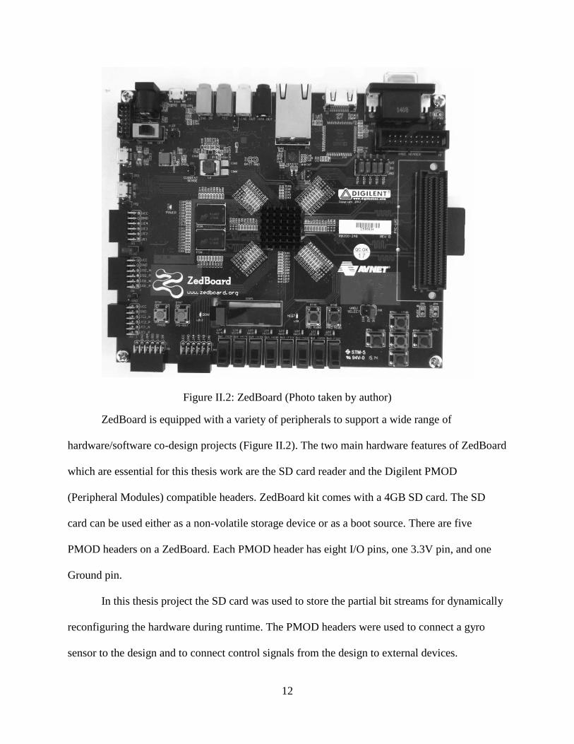
Figure II.2: ZedBoard (Photo taken by author)
ZedBoard is equipped with a variety of peripherals to support a wide range of
hardware/software co-design projects (Figure II.2). The two main hardware features of ZedBoard
which are essential for this thesis work are the SD card reader and the Digilent PMOD
(Peripheral Modules) compatible headers. ZedBoard kit comes with a 4GB SD card. The SD
card can be used either as a non-volatile storage device or as a boot source. There are five
PMOD headers on a ZedBoard. Each PMOD header has eight I/O pins, one 3.3V pin, and one
Ground pin.
In this thesis project the SD card was used to store the partial bit streams for dynamically
reconfiguring the hardware during runtime. The PMOD headers were used to connect a gyro
sensor to the design and to connect control signals from the design to external devices.
13
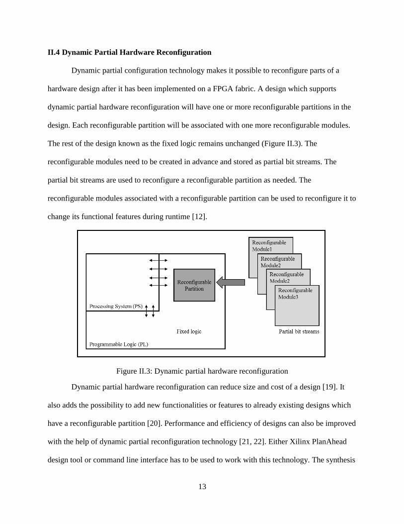
II.4 Dynamic Partial Hardware Reconfiguration
Dynamic partial configuration technology makes it possible to reconfigure parts of a
hardware design after it has been implemented on a FPGA fabric. A design which supports
dynamic partial hardware reconfiguration will have one or more reconfigurable partitions in the
design. Each reconfigurable partition will be associated with one more reconfigurable modules.
The rest of the design known as the fixed logic remains unchanged (Figure II.3). The
reconfigurable modules need to be created in advance and stored as partial bit streams. The
partial bit streams are used to reconfigure a reconfigurable partition as needed. The
reconfigurable modules associated with a reconfigurable partition can be used to reconfigure it to
change its functional features during runtime [12].
Figure II.3: Dynamic partial hardware reconfiguration
Dynamic partial hardware reconfiguration can reduce size and cost of a design [19]. It
also adds the possibility to add new functionalities or features to already existing designs which
have a reconfigurable partition [20]. Performance and efficiency of designs can also be improved
with the help of dynamic partial reconfiguration technology [21, 22]. Either Xilinx PlanAhead
design tool or command line interface has to be used to work with this technology. The synthesis
14
of reconfigurable modules has to be done outside PlanAhead. Clock modifying logic has to be
avoided in reconfigurable partitions. It should be implemented as a part of the fixed logic.
Bidirectional I/O also should be avoided in reconfigurable modules [13].
In this thesis work dynamic partial hardware reconfiguration is used to dynamically
switch multirotor arm configurations. A part of the hardware design is implemented as a
reconfigurable partition. The hardware logic for each multirotor arm configuration is stored as
reconfigurable module partial bit streams. Using dynamic partial reconfiguration we can reduce
size of the system compared to a design implemented without runtime partial reconfiguration. In
addition it also gives us the flexibility to add additional functionality by adding new
reconfigurable modules. Hardware accelerator for software processes can be designed using
dynamic partial reconfiguration which makes it possible to modify the accelerator using a partial
bit stream instead for recreating the hardware accelerator with the new functionality [23].
II.5 Hardware Components
II.5.1 Multirotor
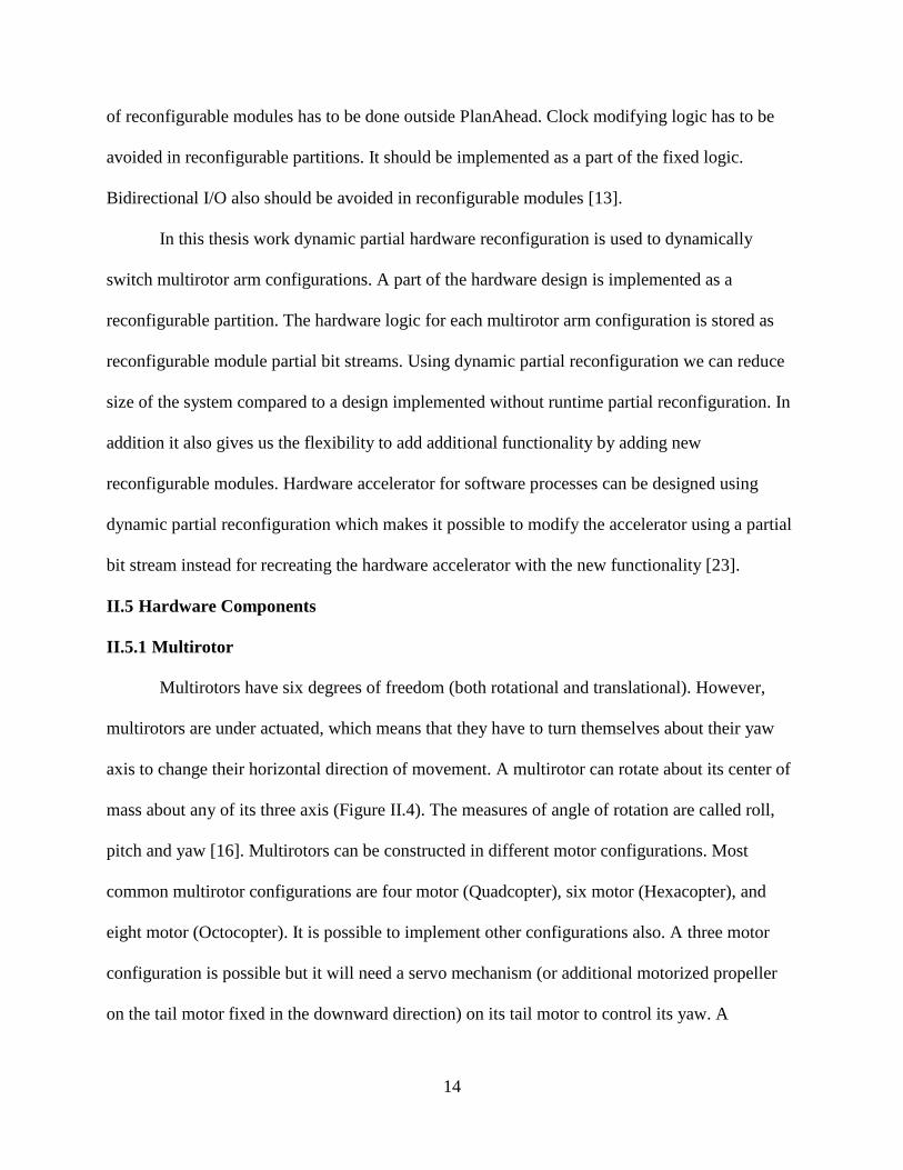
Multirotors have six degrees of freedom (both rotational and translational). However,
multirotors are under actuated, which means that they have to turn themselves about their yaw
axis to change their horizontal direction of movement. A multirotor can rotate about its center of
mass about any of its three axis (Figure II.4). The measures of angle of rotation are called roll,
pitch and yaw [16]. Multirotors can be constructed in different motor configurations. Most
common multirotor configurations are four motor (Quadcopter), six motor (Hexacopter), and
eight motor (Octocopter). It is possible to implement other configurations also. A three motor
configuration is possible but it will need a servo mechanism (or additional motorized propeller
on the tail motor fixed in the downward direction) on its tail motor to control its yaw. A
15
Quadcopter is the simplest configuration, but it will crash if any one of its motors malfunction. A
Hexacopter and Octocopter add redundancy to a multirotor making it more reliable. A
Hexacopter or an Octocopter can be landed safely even if one of its motors malfunction.
Moreover, additional motors add more load carrying capacity to the multirotor. Multirotor
technology brings together elements of various domains of engineering.
Figure II.4: Roll, pitch, and yaw of a multirotor
The objective of this study is to develop an adaptive controller which can switch between
different multirotor arm configurations. Currently, it is not our intention to develop a new
multirotor or a multirotor control algorithm. So a commercially available multirotor platform
(XAircraft DIY Hexa) was used to test the design.
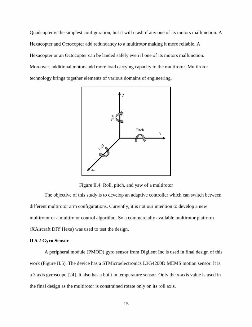
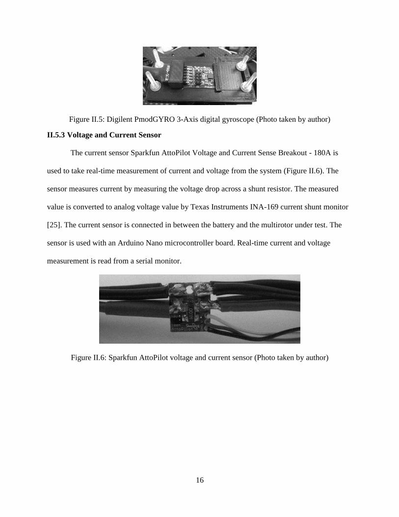
II.5.2 Gyro Sensor
A peripheral module (PMOD) gyro sensor from Digilent Inc is used in final design of this
work (Figure II.5). The device has a STMicroelectronics L3G4200D MEMS motion sensor. It is
a 3 axis gyroscope [24]. It also has a built in temperature sensor. Only the x-axis value is used in
the final design as the multirotor is constrained rotate only on its roll axis.
16
Figure II.5: Digilent PmodGYRO 3-Axis digital gyroscope (Photo taken by author)
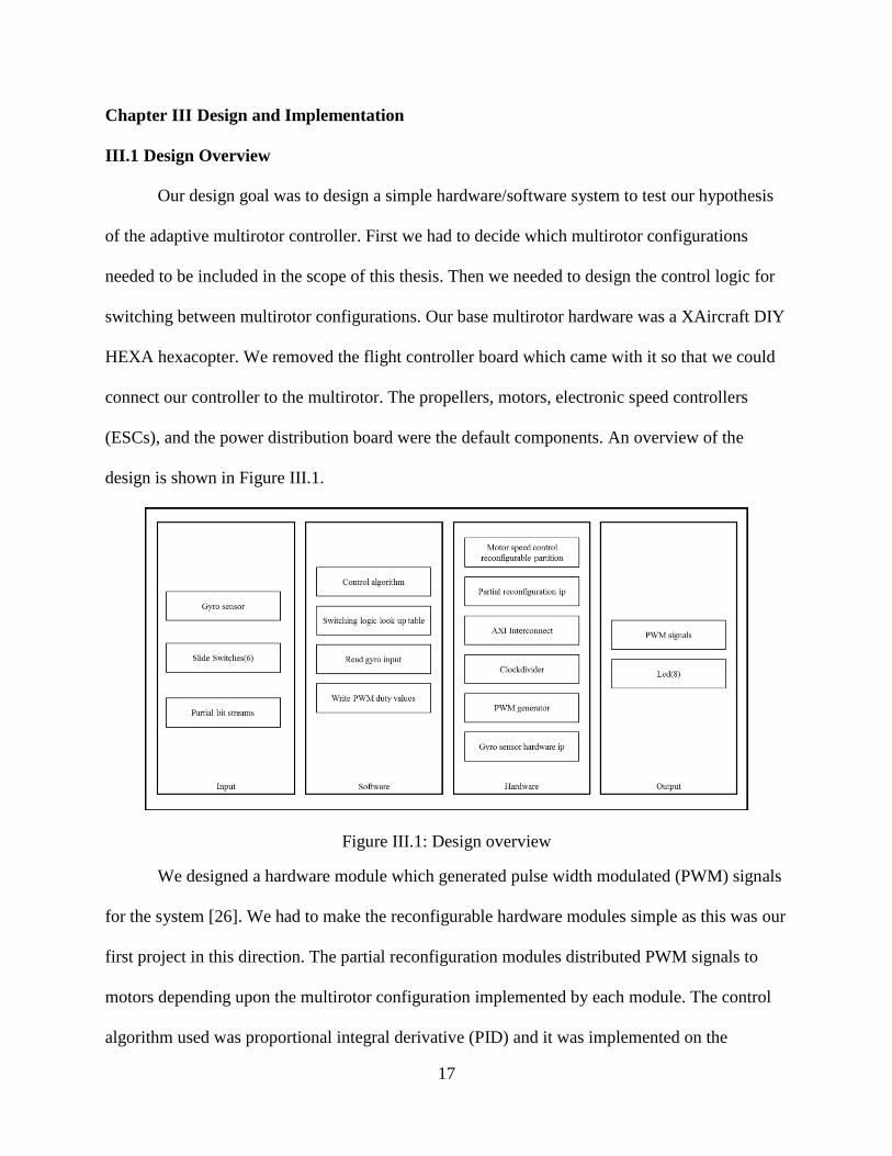
II.5.3 Voltage and Current Sensor
The current sensor Sparkfun AttoPilot Voltage and Current Sense Breakout - 180A is
used to take real-time measurement of current and voltage from the system (Figure II.6). The
sensor measures current by measuring the voltage drop across a shunt resistor. The measured
value is converted to analog voltage value by Texas Instruments INA-169 current shunt monitor
[25]. The current sensor is connected in between the battery and the multirotor under test. The
sensor is used with an Arduino Nano microcontroller board. Real-time current and voltage
measurement is read from a serial monitor.
Figure II.6: Sparkfun AttoPilot voltage and current sensor (Photo taken by author)
17
Chapter III Design and Implementation
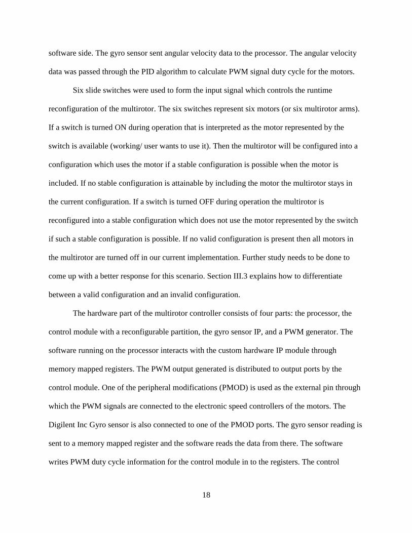
III.1 Design Overview
Our design goal was to design a simple hardware/software system to test our hypothesis
of the adaptive multirotor controller. First we had to decide which multirotor configurations
needed to be included in the scope of this thesis. Then we needed to design the control logic for
switching between multirotor configurations. Our base multirotor hardware was a XAircraft DIY
HEXA hexacopter. We removed the flight controller board which came with it so that we could
connect our controller to the multirotor. The propellers, motors, electronic speed controllers
(ESCs), and the power distribution board were the default components. An overview of the
design is shown in Figure III.1.
Figure III.1: Design overview
We designed a hardware module which generated pulse width modulated (PWM) signals
for the system [26]. We had to make the reconfigurable hardware modules simple as this was our
first project in this direction. The partial reconfiguration modules distributed PWM signals to
motors depending upon the multirotor configuration implemented by each module. The control
algorithm used was proportional integral derivative (PID) and it was implemented on the
18
software side. The gyro sensor sent angular velocity data to the processor. The angular velocity
data was passed through the PID algorithm to calculate PWM signal duty cycle for the motors.
Six slide switches were used to form the input signal which controls the runtime
reconfiguration of the multirotor. The six switches represent six motors (or six multirotor arms).
If a switch is turned ON during operation that is interpreted as the motor represented by the
switch is available (working/ user wants to use it). Then the multirotor will be configured into a
configuration which uses the motor if a stable configuration is possible when the motor is
included. If no stable configuration is attainable by including the motor the multirotor stays in
the current configuration. If a switch is turned OFF during operation the multirotor is
reconfigured into a stable configuration which does not use the motor represented by the switch
if such a stable configuration is possible. If no valid configuration is present then all motors in
the multirotor are turned off in our current implementation. Further study needs to be done to
come up with a better response for this scenario. Section III.3 explains how to differentiate
between a valid configuration and an invalid configuration.
The hardware part of the multirotor controller consists of four parts: the processor, the
control module with a reconfigurable partition, the gyro sensor IP, and a PWM generator. The
software running on the processor interacts with the custom hardware IP module through
memory mapped registers. The PWM output generated is distributed to output ports by the
control module. One of the peripheral modifications (PMOD) is used as the external pin through
which the PWM signals are connected to the electronic speed controllers of the motors. The
Digilent Inc Gyro sensor is also connected to one of the PMOD ports. The gyro sensor reading is
sent to a memory mapped register and the software reads the data from there. The software
writes PWM duty cycle information for the control module in to the registers. The control
19
module uses this information to drive the PWM generator to produce PWM signals with the
required duty cycle.
III.2 Multirotor Configurations Considered in this Project
We had to choose the multirotor configurations that could be tested using our
experimental setup. Our base system was a hexacopter. Therefore, our choices were a ‘six motor’
configuration, three ‘four motor’ configurations, and two ‘three motor’ configurations. We
acknowledge that if we change the configuration starting with six motors the yaw angular
momentum will be unbalanced in most of the other configurations. A potential solution for this
issue will be to use two motors per arm one pointing upwards and one pointing downwards. It is
beyond the scope of this thesis. Further studies need to be done to test this solution.
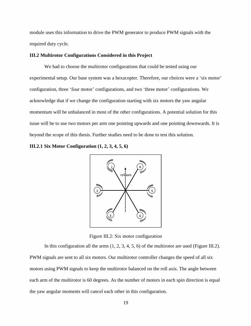
III.2.1 Six Motor Configuration (1, 2, 3, 4, 5, 6)
Figure III.2: Six motor configuration
In this configuration all the arms (1, 2, 3, 4, 5, 6) of the multirotor are used (Figure III.2).
PWM signals are sent to all six motors. Our multirotor controller changes the speed of all six
motors using PWM signals to keep the multirotor balanced on the roll axis. The angle between
each arm of the multirotor is 60 degrees. As the number of motors in each spin direction is equal
the yaw angular moments will cancel each other in this configuration.
20
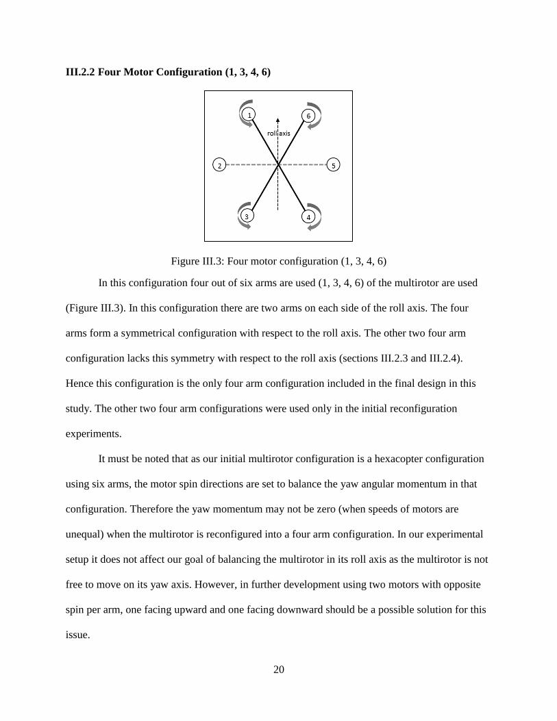
III.2.2 Four Motor Configuration (1, 3, 4, 6)
Figure III.3: Four motor configuration (1, 3, 4, 6)
In this configuration four out of six arms are used (1, 3, 4, 6) of the multirotor are used
(Figure III.3). In this configuration there are two arms on each side of the roll axis. The four
arms form a symmetrical configuration with respect to the roll axis. The other two four arm
configuration lacks this symmetry with respect to the roll axis (sections III.2.3 and III.2.4).
Hence this configuration is the only four arm configuration included in the final design in this
study. The other two four arm configurations were used only in the initial reconfiguration
experiments.
It must be noted that as our initial multirotor configuration is a hexacopter configuration
using six arms, the motor spin directions are set to balance the yaw angular momentum in that
configuration. Therefore the yaw momentum may not be zero (when speeds of motors are
unequal) when the multirotor is reconfigured into a four arm configuration. In our experimental
setup it does not affect our goal of balancing the multirotor in its roll axis as the multirotor is not
free to move on its yaw axis. However, in further development using two motors with opposite
spin per arm, one facing upward and one facing downward should be a possible solution for this
issue.
21
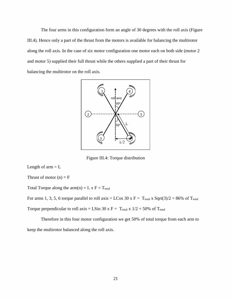
The four arms in this configuration form an angle of 30 degrees with the roll axis (Figure
III.4). Hence only a part of the thrust from the motors is available for balancing the multirotor
along the roll axis. In the case of six motor configuration one motor each on both side (motor 2
and motor 5) supplied their full thrust while the others supplied a part of their thrust for
balancing the multirotor on the roll axis.
Figure III.4: Torque distribution
Length of arm = L
Thrust of motor (n) = F
Total Torque along the arm(n) = L x F = Ttotal
For arms 1, 3, 5, 6 torque parallel to roll axis = LCos 30 x F = Ttotal x Sqrt(3)/2 = 86% of Ttotal
Torque perpendicular to roll axis = LSin 30 x F = Ttotal x 1/2 = 50% of Ttotal
Therefore in this four motor configuration we get 50% of total torque from each arm to
keep the multirotor balanced along the roll axis.
22
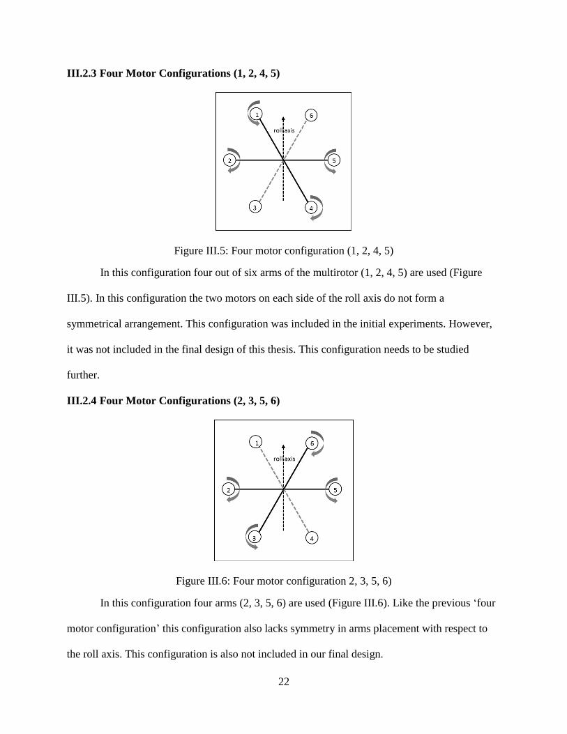
III.2.3 Four Motor Configurations (1, 2, 4, 5)
Figure III.5: Four motor configuration (1, 2, 4, 5)
In this configuration four out of six arms of the multirotor (1, 2, 4, 5) are used (Figure
III.5). In this configuration the two motors on each side of the roll axis do not form a
symmetrical arrangement. This configuration was included in the initial experiments. However,
it was not included in the final design of this thesis. This configuration needs to be studied
further.
III.2.4 Four Motor Configurations (2, 3, 5, 6)
Figure III.6: Four motor configuration 2, 3, 5, 6)
In this configuration four arms (2, 3, 5, 6) are used (Figure III.6). Like the previous ‘four
motor configuration’ this configuration also lacks symmetry in arms placement with respect to
the roll axis. This configuration is also not included in our final design.
23
It must be also noted that in the last two of the four arm configurations, the orientation of
the multirotor with respect to the roll axis has shifted as the active arms are not symmetrically
placed. In other words the current roll axis will lose its meaning in the last two configurations.
This can be a concern in the future development of this platform. It might be essential for a
multirotor to maintain its initial orientation if it is carrying equipment which is calibrated with
respect to the initial orientation.
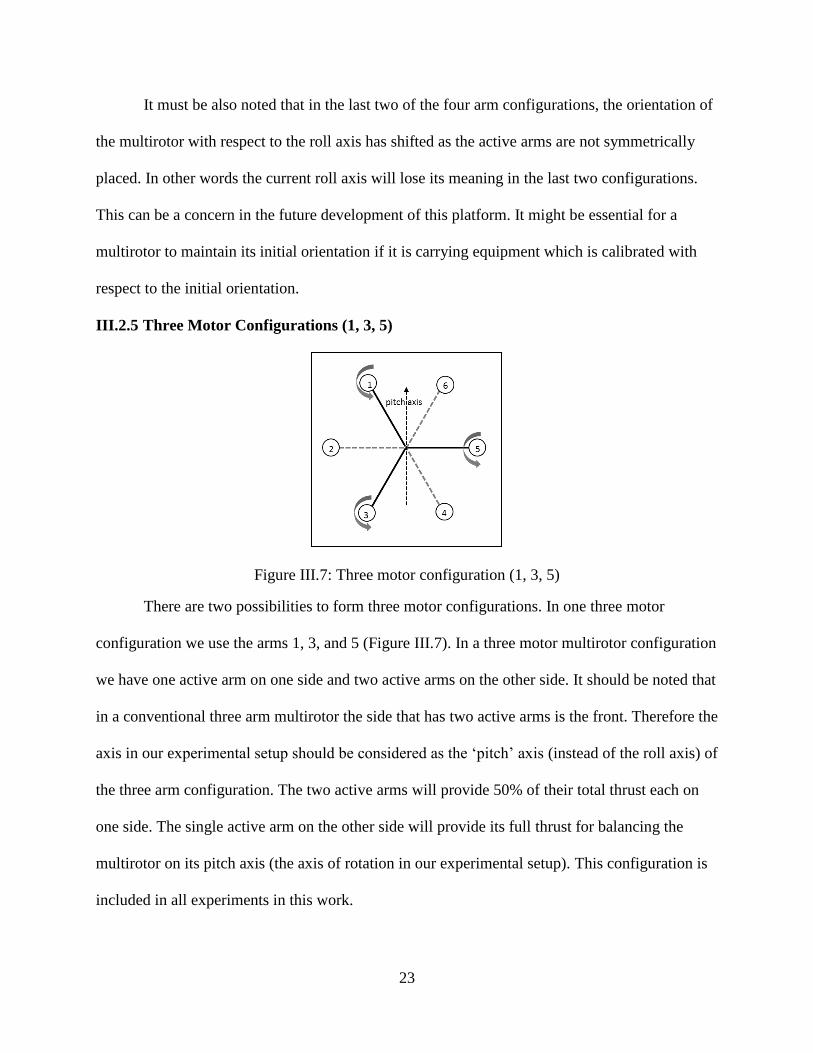
III.2.5 Three Motor Configurations (1, 3, 5)
Figure III.7: Three motor configuration (1, 3, 5)
There are two possibilities to form three motor configurations. In one three motor
configuration we use the arms 1, 3, and 5 (Figure III.7). In a three motor multirotor configuration
we have one active arm on one side and two active arms on the other side. It should be noted that
in a conventional three arm multirotor the side that has two active arms is the front. Therefore the
axis in our experimental setup should be considered as the ‘pitch’ axis (instead of the roll axis) of
the three arm configuration. The two active arms will provide 50% of their total thrust each on
one side. The single active arm on the other side will provide its full thrust for balancing the
multirotor on its pitch axis (the axis of rotation in our experimental setup). This configuration is
included in all experiments in this work.
24
III.2.6 Three Motor Configurations (2, 4, 6)
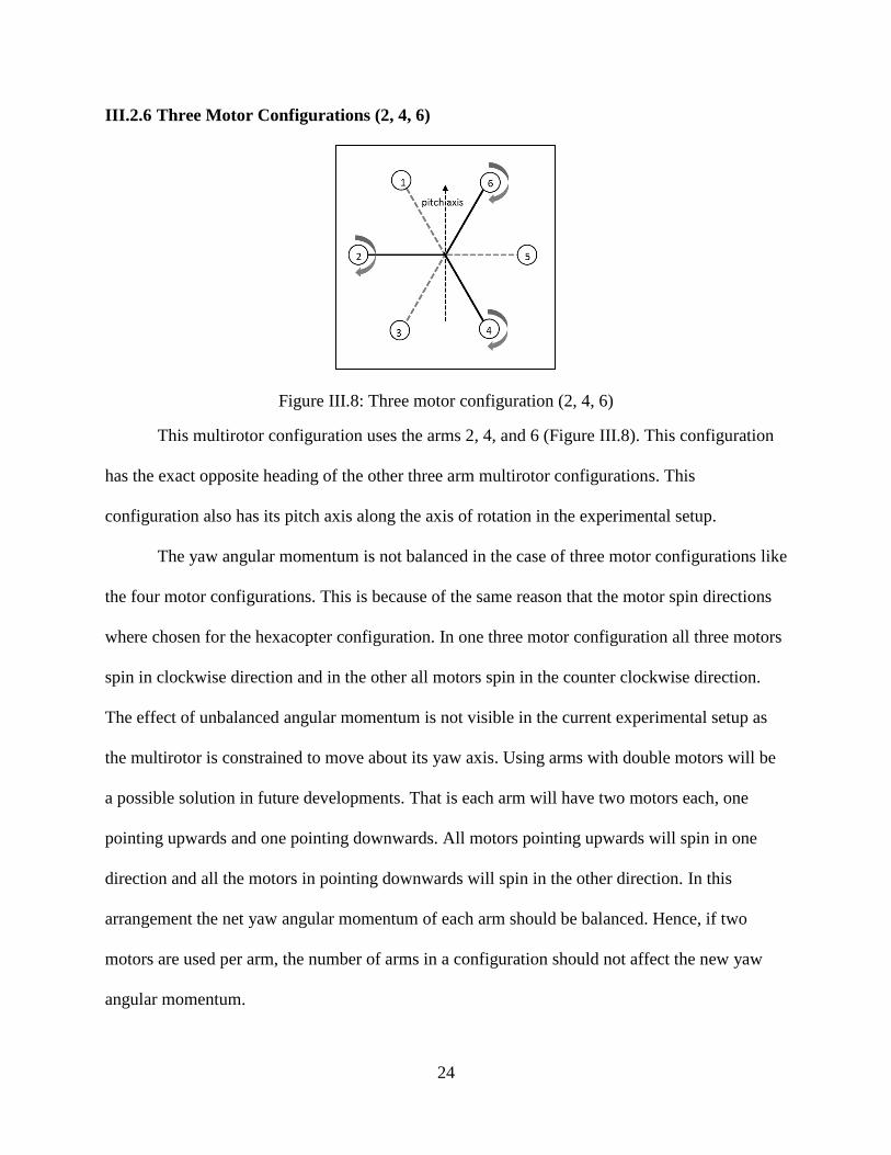
Figure III.8: Three motor configuration (2, 4, 6)
This multirotor configuration uses the arms 2, 4, and 6 (Figure III.8). This configuration
has the exact opposite heading of the other three arm multirotor configurations. This
configuration also has its pitch axis along the axis of rotation in the experimental setup.
The yaw angular momentum is not balanced in the case of three motor configurations like
the four motor configurations. This is because of the same reason that the motor spin directions
where chosen for the hexacopter configuration. In one three motor configuration all three motors
spin in clockwise direction and in the other all motors spin in the counter clockwise direction.
The effect of unbalanced angular momentum is not visible in the current experimental setup as
the multirotor is constrained to move about its yaw axis. Using arms with double motors will be
a possible solution in future developments. That is each arm will have two motors each, one
pointing upwards and one pointing downwards. All motors pointing upwards will spin in one
direction and all the motors in pointing downwards will spin in the other direction. In this
arrangement the net yaw angular momentum of each arm should be balanced. Hence, if two
motors are used per arm, the number of arms in a configuration should not affect the new yaw
angular momentum.
25
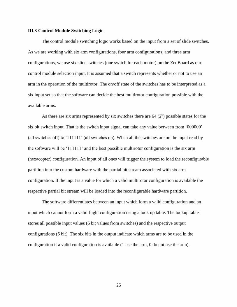
III.3 Control Module Switching Logic
The control module switching logic works based on the input from a set of slide switches.
As we are working with six arm configurations, four arm configurations, and three arm
configurations, we use six slide switches (one switch for each motor) on the ZedBoard as our
control module selection input. It is assumed that a switch represents whether or not to use an
arm in the operation of the multirotor. The on/off state of the switches has to be interpreted as a
six input set so that the software can decide the best multirotor configuration possible with the
available arms.
As there are six arms represented by six switches there are 64 (26) possible states for the
six bit switch input. That is the switch input signal can take any value between from ‘000000’
(all switches off) to ‘111111’ (all switches on). When all the switches are on the input read by
the software will be ‘111111’ and the best possible multirotor configuration is the six arm
(hexacopter) configuration. An input of all ones will trigger the system to load the reconfigurable
partition into the custom hardware with the partial bit stream associated with six arm
configuration. If the input is a value for which a valid multirotor configuration is available the
respective partial bit stream will be loaded into the reconfigurable hardware partition.
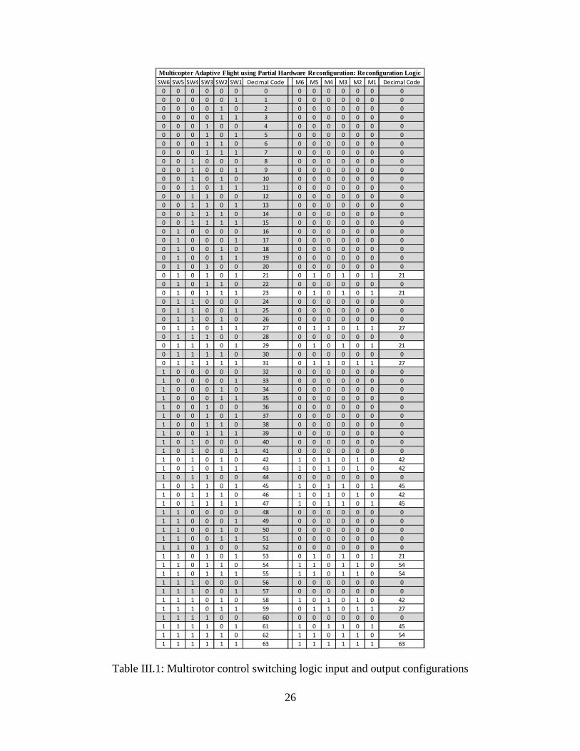
The software differentiates between an input which form a valid configuration and an
input which cannot form a valid flight configuration using a look up table. The lookup table
stores all possible input values (6 bit values from switches) and the respective output
configurations (6 bit). The six bits in the output indicate which arms are to be used in the
configuration if a valid configuration is available (1 use the arm, 0 do not use the arm).
26
Table III.1: Multirotor control switching logic input and output configurations
SW6 SW5 SW4 SW3 SW2 SW1 Decimal Code M6 M5 M4 M3 M2 M1 Decimal Code
0 0 0 0 0 0 0 0 0 0 0 0 0 0
0 0 0 0 0 1 1 0 0 0 0 0 0 0
0 0 0 0 1 0 2 0 0 0 0 0 0 0
0 0 0 0 1 1 3 0 0 0 0 0 0 0
0 0 0 1 0 0 4 0 0 0 0 0 0 0
0 0 0 1 0 1 5 0 0 0 0 0 0 0
0 0 0 1 1 0 6 0 0 0 0 0 0 0
0 0 0 1 1 1 7 0 0 0 0 0 0 0
0 0 1 0 0 0 8 0 0 0 0 0 0 0
0 0 1 0 0 1 9 0 0 0 0 0 0 0
0 0 1 0 1 0 10 0 0 0 0 0 0 0
0 0 1 0 1 1 11 0 0 0 0 0 0 0
0 0 1 1 0 0 12 0 0 0 0 0 0 0
0 0 1 1 0 1 13 0 0 0 0 0 0 0
0 0 1 1 1 0 14 0 0 0 0 0 0 0
0 0 1 1 1 1 15 0 0 0 0 0 0 0
0 1 0 0 0 0 16 0 0 0 0 0 0 0
0 1 0 0 0 1 17 0 0 0 0 0 0 0
0 1 0 0 1 0 18 0 0 0 0 0 0 0
0 1 0 0 1 1 19 0 0 0 0 0 0 0
0 1 0 1 0 0 20 0 0 0 0 0 0 0
0 1 0 1 0 1 21 0 1 0 1 0 1 21
0 1 0 1 1 0 22 0 0 0 0 0 0 0
0 1 0 1 1 1 23 0 1 0 1 0 1 21
0 1 1 0 0 0 24 0 0 0 0 0 0 0
0 1 1 0 0 1 25 0 0 0 0 0 0 0
0 1 1 0 1 0 26 0 0 0 0 0 0 0
0 1 1 0 1 1 27 0 1 1 0 1 1 27
0 1 1 1 0 0 28 0 0 0 0 0 0 0
0 1 1 1 0 1 29 0 1 0 1 0 1 21
0 1 1 1 1 0 30 0 0 0 0 0 0 0
0 1 1 1 1 1 31 0 1 1 0 1 1 27
1 0 0 0 0 0 32 0 0 0 0 0 0 0
1 0 0 0 0 1 33 0 0 0 0 0 0 0
1 0 0 0 1 0 34 0 0 0 0 0 0 0
1 0 0 0 1 1 35 0 0 0 0 0 0 0
1 0 0 1 0 0 36 0 0 0 0 0 0 0
1 0 0 1 0 1 37 0 0 0 0 0 0 0
1 0 0 1 1 0 38 0 0 0 0 0 0 0
1 0 0 1 1 1 39 0 0 0 0 0 0 0
1 0 1 0 0 0 40 0 0 0 0 0 0 0
1 0 1 0 0 1 41 0 0 0 0 0 0 0
1 0 1 0 1 0 42 1 0 1 0 1 0 42
1 0 1 0 1 1 43 1 0 1 0 1 0 42
1 0 1 1 0 0 44 0 0 0 0 0 0 0
1 0 1 1 0 1 45 1 0 1 1 0 1 45
1 0 1 1 1 0 46 1 0 1 0 1 0 42
1 0 1 1 1 1 47 1 0 1 1 0 1 45
1 1 0 0 0 0 48 0 0 0 0 0 0 0
1 1 0 0 0 1 49 0 0 0 0 0 0 0
1 1 0 0 1 0 50 0 0 0 0 0 0 0
1 1 0 0 1 1 51 0 0 0 0 0 0 0
1 1 0 1 0 0 52 0 0 0 0 0 0 0
1 1 0 1 0 1 53 0 1 0 1 0 1 21
1 1 0 1 1 0 54 1 1 0 1 1 0 54
1 1 0 1 1 1 55 1 1 0 1 1 0 54
1 1 1 0 0 0 56 0 0 0 0 0 0 0
1 1 1 0 0 1 57 0 0 0 0 0 0 0
1 1 1 0 1 0 58 1 0 1 0 1 0 42
1 1 1 0 1 1 59 0 1 1 0 1 1 27
1 1 1 1 0 0 60 0 0 0 0 0 0 0
1 1 1 1 0 1 61 1 0 1 1 0 1 45
1 1 1 1 1 0 62 1 1 0 1 1 0 54
1 1 1 1 1 1 63 1 1 1 1 1 1 63
Multicopter Adaptive Flight using Partial Hardware Reconfiguration: Reconfiguration Logic
27
Table III.1 lists all possible input from the switches. All the rows which are highlighted
in gray do not have a stable (valid) configuration. In that case the multirotor controller will be
reconfigured with a control module which supplies a low PWM duty cycle to the motors such
that no motors will spin. The remaining 18 configurations are the inputs which can get a valid
configuration. For example, the input ‘101111’ (decimal code 47) means that the fifth arm
should not be used (or not working). It is up to the system to check if there are any valid
configurations available without using the arm for which the input bit is ‘0’. A valid
configuration can be achieved by turning of the diametrically opposite arm (arm 2). That logic is
represented as the respective output ‘101101’ (decimal code 45) in the output column.
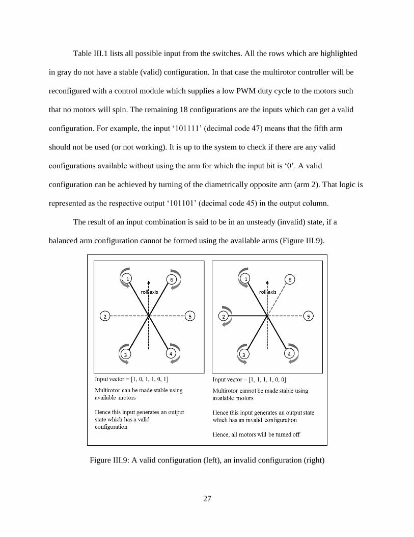
The result of an input combination is said to be in an unsteady (invalid) state, if a
balanced arm configuration cannot be formed using the available arms (Figure III.9).
Figure III.9: A valid configuration (left), an invalid configuration (right)
28
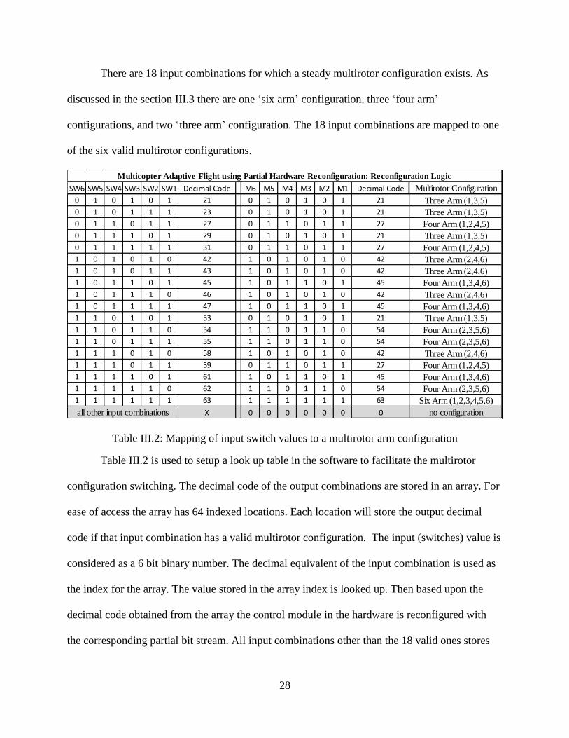
There are 18 input combinations for which a steady multirotor configuration exists. As
discussed in the section III.3 there are one ‘six arm’ configuration, three ‘four arm’
configurations, and two ‘three arm’ configuration. The 18 input combinations are mapped to one
of the six valid multirotor configurations.
Table III.2: Mapping of input switch values to a multirotor arm configuration
Table III.2 is used to setup a look up table in the software to facilitate the multirotor
configuration switching. The decimal code of the output combinations are stored in an array. For
ease of access the array has 64 indexed locations. Each location will store the output decimal
code if that input combination has a valid multirotor configuration. The input (switches) value is
considered as a 6 bit binary number. The decimal equivalent of the input combination is used as
the index for the array. The value stored in the array index is looked up. Then based upon the
decimal code obtained from the array the control module in the hardware is reconfigured with
the corresponding partial bit stream. All input combinations other than the 18 valid ones stores
SW6 SW5 SW4 SW3 SW2 SW1 Decimal Code M6 M5 M4 M3 M2 M1 Decimal Code Multirotor Configuration
0 1 0 1 0 1 21 0 1 0 1 0 1 21 Three Arm (1,3,5)
0 1 0 1 1 1 23 0 1 0 1 0 1 21 Three Arm (1,3,5)
0 1 1 0 1 1 27 0 1 1 0 1 1 27 Four Arm (1,2,4,5)
0 1 1 1 0 1 29 0 1 0 1 0 1 21 Three Arm (1,3,5)
0 1 1 1 1 1 31 0 1 1 0 1 1 27 Four Arm (1,2,4,5)
1 0 1 0 1 0 42 1 0 1 0 1 0 42 Three Arm (2,4,6)
1 0 1 0 1 1 43 1 0 1 0 1 0 42 Three Arm (2,4,6)
1 0 1 1 0 1 45 1 0 1 1 0 1 45 Four Arm (1,3,4,6)
1 0 1 1 1 0 46 1 0 1 0 1 0 42 Three Arm (2,4,6)
1 0 1 1 1 1 47 1 0 1 1 0 1 45 Four Arm (1,3,4,6)
1 1 0 1 0 1 53 0 1 0 1 0 1 21 Three Arm (1,3,5)
1 1 0 1 1 0 54 1 1 0 1 1 0 54 Four Arm (2,3,5,6)
1 1 0 1 1 1 55 1 1 0 1 1 0 54 Four Arm (2,3,5,6)
1 1 1 0 1 0 58 1 0 1 0 1 0 42 Three Arm (2,4,6)
1 1 1 0 1 1 59 0 1 1 0 1 1 27 Four Arm (1,2,4,5)
1 1 1 1 0 1 61 1 0 1 1 0 1 45 Four Arm (1,3,4,6)
1 1 1 1 1 0 62 1 1 0 1 1 0 54 Four Arm (2,3,5,6)
1 1 1 1 1 1 63 1 1 1 1 1 1 63 Six Arm (1,2,3,4,5,6)
X 0 0 0 0 0 0 0 no configuration
Multicopter Adaptive Flight using Partial Hardware Reconfiguration: Reconfiguration Logic
all other input combinations
29
the value ‘0’, indicating that those combination cannot have a stable multirotor configuration. In
that case the reconfigurable partition in the controller is configured with a module which will
turn all the motors off.
III.4 Hardware Design
III.4.1 Design0: Simple Design without Partial Hardware Reconfiguration
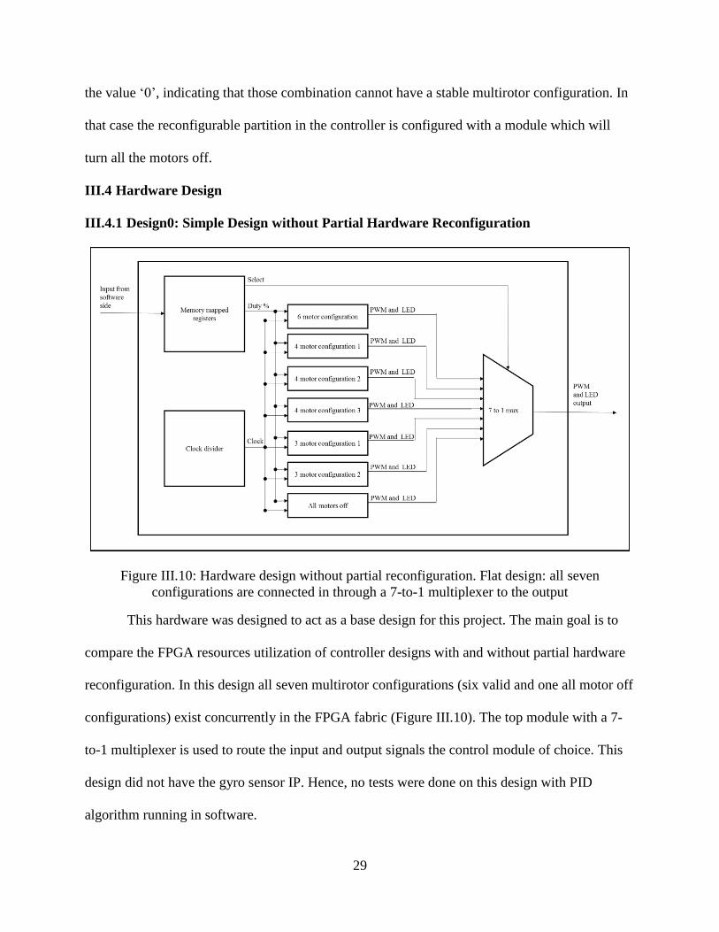
Figure III.10: Hardware design without partial reconfiguration. Flat design: all seven
configurations are connected in through a 7-to-1 multiplexer to the output
This hardware was designed to act as a base design for this project. The main goal is to
compare the FPGA resources utilization of controller designs with and without partial hardware
reconfiguration. In this design all seven multirotor configurations (six valid and one all motor off
configurations) exist concurrently in the FPGA fabric (Figure III.10). The top module with a 7-
to-1 multiplexer is used to route the input and output signals the control module of choice. This
design did not have the gyro sensor IP. Hence, no tests were done on this design with PID
algorithm running in software.
30
This design communicated with the software side through memory mapped resisters. In
this design the PWM duty cycle can be set from the software and the PWM generator produced
the PWM signals. Then the PWM signals were routed to the external PMOD pins through the
multiplexed control modules.
III.4.2 Design1: Hardware Design with a Reconfigurable Partition
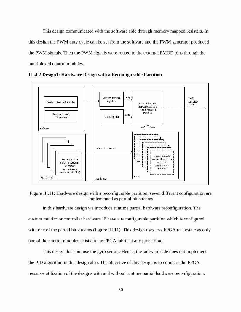
Figure III.11: Hardware design with a reconfigurable partition, seven different configuration are
implemented as partial bit streams
In this hardware design we introduce runtime partial hardware reconfiguration. The
custom multirotor controller hardware IP have a reconfigurable partition which is configured
with one of the partial bit streams (Figure III.11). This design uses less FPGA real estate as only
one of the control modules exists in the FPGA fabric at any given time.
This design does not use the gyro sensor. Hence, the software side does not implement
the PID algorithm in this design also. The objective of this design is to compare the FPGA
resource utilization of the designs with and without runtime partial hardware reconfiguration.
31
The seven control configurations are compiled into partial bit streams and stored in a SD card.
The partial bit streams are stored as ‘.bin’ files in the SD card. In this design the software reads
the partial bit streams stored in the SD card into the RAM. The bit streams are passed to the
reconfigurable partition using the processor configuration access port (PCAP) hardware IP of
Zynq.
III.4.3 Design2: Prototype with PID and Gyro sensor
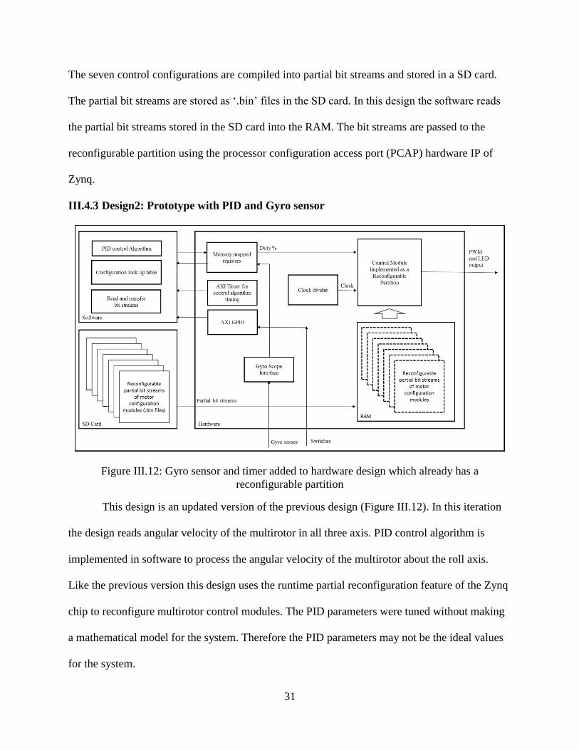
Figure III.12: Gyro sensor and timer added to hardware design which already has a
reconfigurable partition
This design is an updated version of the previous design (Figure III.12). In this iteration
the design reads angular velocity of the multirotor in all three axis. PID control algorithm is
implemented in software to process the angular velocity of the multirotor about the roll axis.
Like the previous version this design uses the runtime partial reconfiguration feature of the Zynq
chip to reconfigure multirotor control modules. The PID parameters were tuned without making
a mathematical model for the system. Therefore the PID parameters may not be the ideal values
for the system.
32
In this work as the multirotor can move only on its roll axis, only the angular velocity
along the x axis is relevant. The angular velocity is processed using the PID control algorithm to
balance the multirotor on its roll axis. The axis of rotation is the roll axis for the one six motor
configuration and for the three four motor configurations. However, technically the axis of
rotation becomes the pitch axis for the two three motor configurations in our experimental setup.
Currently the base throttle (specified as PWM duty cycle) value to the motors is set as a
constant. The range of duty values for the PWM signal are 5% and 11%. These values are based
on the maximum and minimum PWM signals produced by the throttle stick of DX7Se radio
transmitter. The multirotor is fed the initial throttle PWM duty cycle at first. Then PID algorithm
is used to calculate error correction values. The PID function uses the input from the gyro sensor
as the error. The objective of the PID algorithm is to minimize the error registered by the gyro
sensor. When the multirotor is balanced, ideally the gyro sensor should output 0. However, due
to vibration of the multirotor the gyro sensor constantly sends a reading and it almost never sends
out zero. The PID term, the output of the PID function is used to modify the duty cycle for
motors on each side of the roll axis.
Two of the four arm configurations were not used in this design. The four arm
configuration (1, 3, 4, and 6) was the only one used in this design. In the other two
configurations none of their axis of orientation (yaw, pitch, and roll) align with the axis of the
experimental setup. Hence, it is technically meaningless to try to balance those two configuration
about an axis which is at an angle to the arm configuration. Therefore this hardware design
incorporated five multirotor reconfiguration modules. One Six arm configuration, one four arm
configuration, two three arm configurations and a configuration which turned off all motors.
33
As this design uses runtime partial hardware reconfiguration like the previous version of
the hardware, the clock divider was set up as a part of the static hardware logic. However, the
PWM generator module was a part of the reconfigurable module. This is because that the number
of instances of the PWM modules changes depending upon the type of multirotor configuration
being implemented. In addition the gyro sensor hardware IP was also a part of the static
hardware logic.
III.4.4 Design of Individual Control Modules
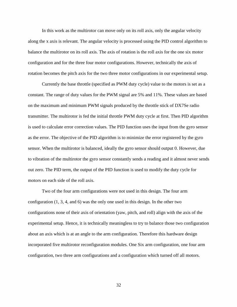
There is a control module design associated with each multirotor configuration (Figure
III.13). These control modules are used to configure the reconfigurable partition in Design 1 and
Design 2. In Design 0 the individual control modules were implemented as concurrent logic on
the FPGA. The functions of the control modules are:
1. Generate PWM signals with respect to PWM duty values set by the software
2. Distribute PWM signals properly to active motors in the configuration
3. Generate output for LEDs to indicate the active motors in the current configuration
The control modules have PWM generators as sub modules. As we are interested in the
motion of our multirotor about its roll axis, we did not setup separate PWM generators for each
motor. All the left side motors are controlled by one PWM generator and all the right side motors
are connected to another PWM generator. The ‘six motor’ configuration has two PWM
generators. One for generating signals for left side motors and the other for right side motors. For
all the other configurations there are three PWM generator sub modules. One for the active
motors on the left side, one for active motors on the right side, and one for generating a 5%
PWM signal for inactive motors in the current configuration. A PWM signal of 5% will keep the
motors at rest. Each control module outputs the six PWM signals as a six bit vector.
34
Figure III.13: Structure of a reconfigurable control module ‘four motor 1‘(1, 3, 4, 6)
Each control module also outputs an eight bit vector to the LEDs. The first six bit
indicate which all of the six motors are active in the current configuration. The seventh bit will
be ‘1’ (and all the other bits ‘0’) for an invalid configuration. The eighth bit is set to ‘1’ for all
valid configurations.
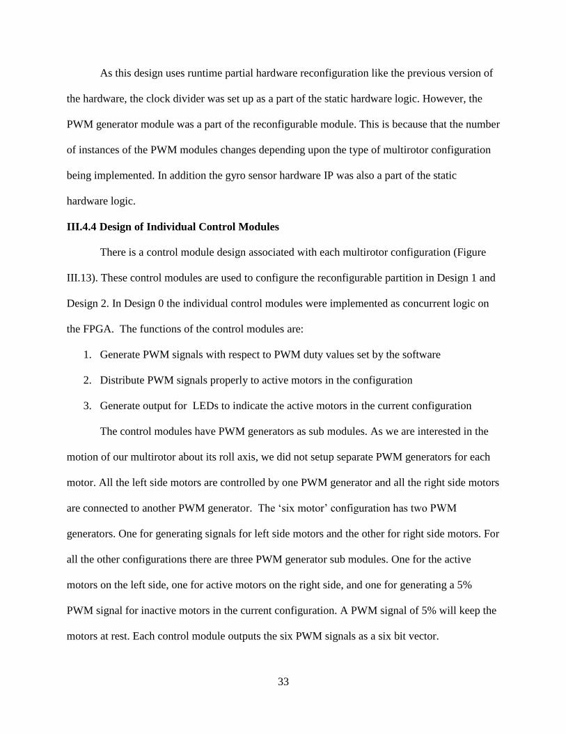
III.4.5 Design of PWM Generator
The motors of the multirotor are driven using Pulse Width Modulated (PWM) signals
[26]. The design parameters of the PWM generator (Figure III.14) were set by measuring the
PWM signals produced by the radio controller (DX7Se) using an oscilloscope. The frequency of
the PWM signals generated by the radio controller was 45 Hz. The DX7Se radio controller
produced PWM signals with a duty of 11% when the throttle stick was at the maximum position.
The duty was 5% when the stick was at the min position. The duty parameter of a PWM signal
determines the strength of a PWM signal. A 100% PWM signal will be a signal which is high
throughout each cycle.
35
The hardware under development used was using a base clock of 100 MHz. Hence clock
dividers were used to scale down the source clock depending upon the period of the PWM signal
to be generated. The frequency of the output PWM signal was chosen as 50 Hz as it was a value
close to 45 Hz which could be easily generated from a scaled down clock derived from the base
clock of 100 MHz.
Figure III.14: PWM generator design
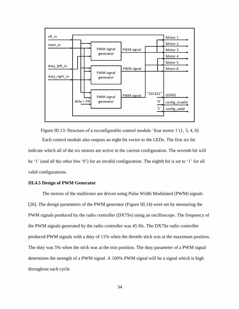
The period parameter of the PWM generator was set depending upon the resolution of
PWM signal needed. As the minimum and maximum duty values are 5% and 11%, if the period
is 100, there will be only seven discrete PWM values which can be generated using the
controller. It is almost impossible to design a controller using such a low resolution. Moreover
the PWM generator module does not work with floating point values. Therefore, in order to get
better resolution in PWM duty values without changing the PWM output frequency we increased
the period parameter of the PWM generator. Increasing the period by an order of 10 (period =
1000) the maximum duty becomes 110 (11% of 1000). The minimum duty at this period will be
50. This will give us 70 PWM duty levels (5.0%, 5.1% … 11%).
In our final design we set the period to 50,000,000. This will give us a minimum duty
cycle of 50,000 (5%) and a maximum duty cycle of 110,000 (11%) (Table III.3). We were tuning
the PID algorithm for balancing the multirotor without mathematically modelling the system. In
addition we were not passing any floating point values to hardware side. Therefore we had to
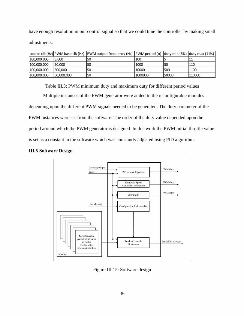
36
have enough resolution in our control signal so that we could tune the controller by making small
adjustments.
Table III.3: PWM minimum duty and maximum duty for different period values
Multiple instances of the PWM generator were added to the reconfigurable modules
depending upon the different PWM signals needed to be generated. The duty parameter of the
PWM instances were set from the software. The order of the duty value depended upon the
period around which the PWM generator is designed. In this work the PWM initial throttle value
is set as a constant in the software which was constantly adjusted using PID algorithm.
III.5 Software Design
Figure III.15: Software design
source clk (Hz) PWM base clk (Hz) PWM output frequency (Hz) PWM period (n) duty min (5%) duty max (11%)
100,000,000 5,000 50 100 5 11
100,000,000 50,000 50 1000 50 110
100,000,000 500,000 50 10000 500 1100
100,000,000 50,000,000 50 1000000 50000 110000
37
The main functions of the software side of the system was to manage input/output, to
implement PID control algorithm, and to manage partial hardware reconfiguration (Figure
III.15).
III.5.1 Input/output
In the scope of this work the objective of the control algorithm is to balance the
multirotor on its roll axis. Hence the angular velocity about the x axis of the gyro sensor was the
input for the PID controller. The PID controller calculates error correction values and it is used
to modify the PWM duty cycle for the PWM generator. The software also gets input from the
slide switches. The input from the six slide switches are decoded into a decimal number. The
decimal code is used as an index to look up the output configuration in the look up table
implemented as a header file.
III.5.2 PID Control Algorithm
The PID control algorithm is implemented as a function which takes in the x axis gyro
sensor data and returns error correction values [17]. In this study the tuning of the PID gains Kp,
Kd, and Ki were done experimentally without using a mathematical model. The period parameter
in the PID generator was set high at 50,000,000 so that the PID controller could make fine
adjustments in the motor speeds in order to balance the multirotor on its roll axis.
III.5.3 Managing Partial Hardware Reconfiguration
The partial reconfiguration of the reconfigurable partition within the hardware design is
managed by the software. All the partial bit streams are stored in an SD card. The software part
reads each partial bit stream in the SD card into the RAM. The output configuration codes in the
output configuration lookup table are associated with one of the available bit streams. When the
input from the slide switches changes, the software will look up the configuration code from the
38
lookup table. Then the bit stream associated with the configuration code is sent to the
reconfigurable partition and the partition is configured with the new multirotor arm
configuration.
In addition the software side has other functions like performing calibration of electronic
speed controllers. It is done to set the highest possible PWM duty and lowest PWM duty in the
electronic speed controllers. The motors can be also tested individually or as a set from the
software side.
39
Chapter IV Experiments and Results
IV.1 Overview
The adaptive multirotor reconfiguration hardware/software system was tested to study its
performance and the relation between various technical parameters of the design. We have
mainly three hardware/software designs to experiment with. The experiments and the
observations are explained in this chapter.
IV.2 Experimental Setup
We needed an experimental setup which we can be used to test the performance of our
hardware/software multirotor controller (Figure IV.1). Either ‘+’ or ‘X’ frame configuration can
be used to test a multirotor [11]. The axis of rotation we chose was the roll axis in the ‘X’
multirotor mode. The reason behind this decision is that in the ‘X’ multirotor mode the arms of
the multirotor are distributed on either side of the axis. There are no arms along the axis of
rotation. This makes it convenient to test the system in different configurations.
Figure IV.1: Experimental setup (Photo taken by author)
40
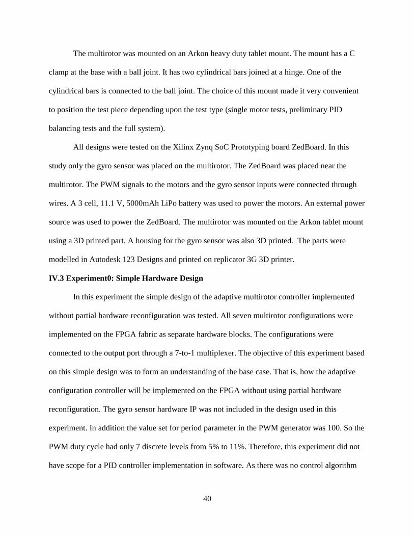
The multirotor was mounted on an Arkon heavy duty tablet mount. The mount has a C
clamp at the base with a ball joint. It has two cylindrical bars joined at a hinge. One of the
cylindrical bars is connected to the ball joint. The choice of this mount made it very convenient
to position the test piece depending upon the test type (single motor tests, preliminary PID
balancing tests and the full system).
All designs were tested on the Xilinx Zynq SoC Prototyping board ZedBoard. In this
study only the gyro sensor was placed on the multirotor. The ZedBoard was placed near the
multirotor. The PWM signals to the motors and the gyro sensor inputs were connected through
wires. A 3 cell, 11.1 V, 5000mAh LiPo battery was used to power the motors. An external power
source was used to power the ZedBoard. The multirotor was mounted on the Arkon tablet mount
using a 3D printed part. A housing for the gyro sensor was also 3D printed. The parts were
modelled in Autodesk 123 Designs and printed on replicator 3G 3D printer.
IV.3 Experiment0: Simple Hardware Design
In this experiment the simple design of the adaptive multirotor controller implemented
without partial hardware reconfiguration was tested. All seven multirotor configurations were
implemented on the FPGA fabric as separate hardware blocks. The configurations were
connected to the output port through a 7-to-1 multiplexer. The objective of this experiment based
on this simple design was to form an understanding of the base case. That is, how the adaptive
configuration controller will be implemented on the FPGA without using partial hardware
reconfiguration. The gyro sensor hardware IP was not included in the design used in this
experiment. In addition the value set for period parameter in the PWM generator was 100. So the
PWM duty cycle had only 7 discrete levels from 5% to 11%. Therefore, this experiment did not
have scope for a PID controller implementation in software. As there was no control algorithm
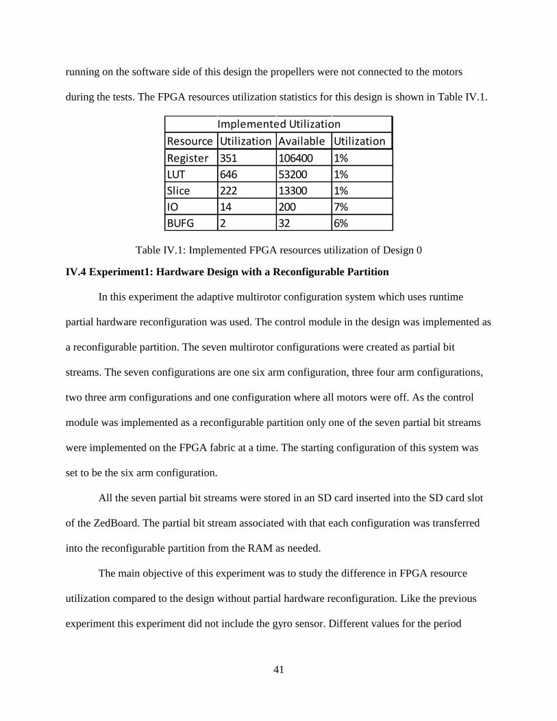
41
running on the software side of this design the propellers were not connected to the motors
during the tests. The FPGA resources utilization statistics for this design is shown in Table IV.1.
Table IV.1: Implemented FPGA resources utilization of Design 0
IV.4 Experiment1: Hardware Design with a Reconfigurable Partition
In this experiment the adaptive multirotor configuration system which uses runtime
partial hardware reconfiguration was used. The control module in the design was implemented as
a reconfigurable partition. The seven multirotor configurations were created as partial bit
streams. The seven configurations are one six arm configuration, three four arm configurations,
two three arm configurations and one configuration where all motors were off. As the control
module was implemented as a reconfigurable partition only one of the seven partial bit streams
were implemented on the FPGA fabric at a time. The starting configuration of this system was
set to be the six arm configuration.
All the seven partial bit streams were stored in an SD card inserted into the SD card slot
of the ZedBoard. The partial bit stream associated with that each configuration was transferred
into the reconfigurable partition from the RAM as needed.
The main objective of this experiment was to study the difference in FPGA resource
utilization compared to the design without partial hardware reconfiguration. Like the previous
experiment this experiment did not include the gyro sensor. Different values for the period
Resource Utilization Available Utilization
Register 351 106400 1%
LUT 646 53200 1%
Slice 222 13300 1%
IO 14 200 7%
BUFG 2 32 6%
Implemented Utilization
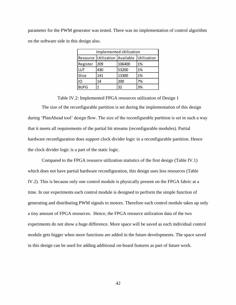
42
parameter for the PWM generator was tested. There was no implementation of control algorithm
on the software side in this design also.
Table IV.2: Implemented FPGA resources utilization of Design 1
The size of the reconfigurable partition is set during the implementation of this design
during ‘PlanAhead tool’ design flow. The size of the reconfigurable partition is set in such a way
that it meets all requirements of the partial bit streams (reconfigurable modules). Partial
hardware reconfiguration does support clock divider logic in a reconfigurable partition. Hence
the clock divider logic is a part of the static logic.
Compared to the FPGA resource utilization statistics of the first design (Table IV.1)
which does not have partial hardware reconfiguration, this design uses less resources (Table
IV.2). This is because only one control module is physically present on the FPGA fabric at a
time. In our experiments each control module is designed to perform the simple function of
generating and distributing PWM signals to motors. Therefore each control module takes up only
a tiny amount of FPGA resources. Hence, the FPGA resource utilization data of the two
experiments do not show a huge difference. More space will be saved as each individual control
module gets bigger when more functions are added in the future developments. The space saved
in this design can be used for adding additional on-board features as part of future work.
Resource Utilization Available Utilization
Register 209 106400 1%
LUT 430 53200 1%
Slice 141 13300 1%
IO 14 200 7%
BUFG 1 32 3%
Implemented Utilization
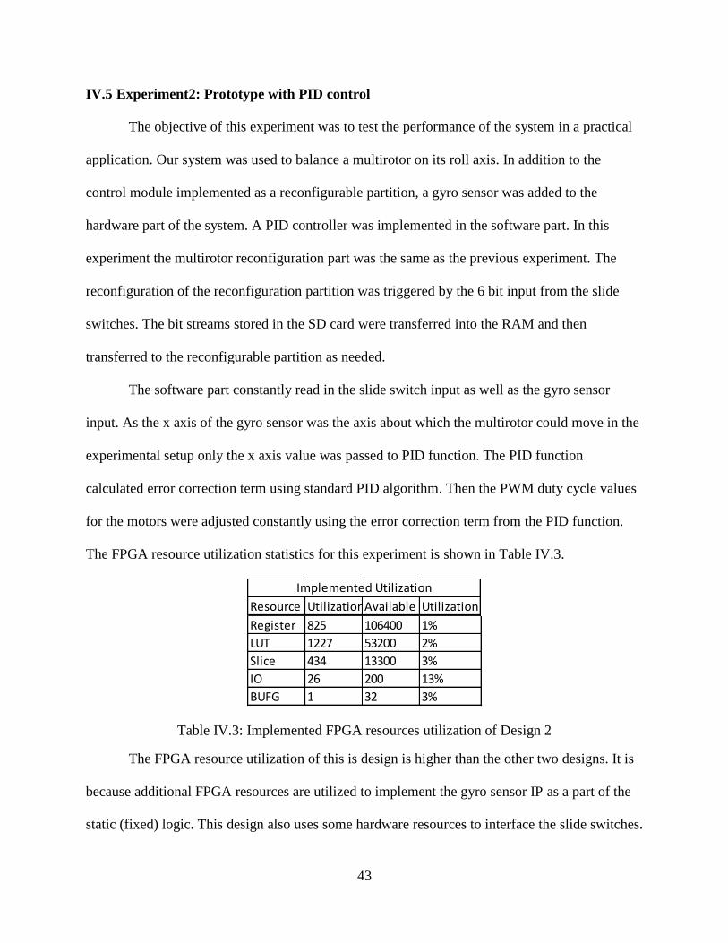
43
IV.5 Experiment2: Prototype with PID control
The objective of this experiment was to test the performance of the system in a practical
application. Our system was used to balance a multirotor on its roll axis. In addition to the
control module implemented as a reconfigurable partition, a gyro sensor was added to the
hardware part of the system. A PID controller was implemented in the software part. In this
experiment the multirotor reconfiguration part was the same as the previous experiment. The
reconfiguration of the reconfiguration partition was triggered by the 6 bit input from the slide
switches. The bit streams stored in the SD card were transferred into the RAM and then
transferred to the reconfigurable partition as needed.
The software part constantly read in the slide switch input as well as the gyro sensor
input. As the x axis of the gyro sensor was the axis about which the multirotor could move in the
experimental setup only the x axis value was passed to PID function. The PID function
calculated error correction term using standard PID algorithm. Then the PWM duty cycle values
for the motors were adjusted constantly using the error correction term from the PID function.
The FPGA resource utilization statistics for this experiment is shown in Table IV.3.
Table IV.3: Implemented FPGA resources utilization of Design 2
The FPGA resource utilization of this is design is higher than the other two designs. It is
because additional FPGA resources are utilized to implement the gyro sensor IP as a part of the
static (fixed) logic. This design also uses some hardware resources to interface the slide switches.
Resource UtilizationAvailable Utilization
Register 825 106400 1%
LUT 1227 53200 2%
Slice 434 13300 3%
IO 26 200 13%
BUFG 1 32 3%
Implemented Utilization
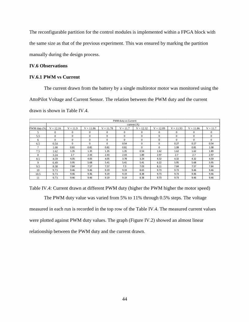
44
The reconfigurable partition for the control modules is implemented within a FPGA block with
the same size as that of the previous experiment. This was ensured by marking the partition
manually during the design process.
IV.6 Observations
IV.6.1 PWM vs Current
The current drawn from the battery by a single multirotor motor was monitored using the
AttoPilot Voltage and Current Sensor. The relation between the PWM duty and the current
drawn is shown in Table IV.4.
Table IV.4: Current drawn at different PWM duty (higher the PWM higher the motor speed)
The PWM duty value was varied from 5% to 11% through 0.5% steps. The voltage
measured in each run is recorded in the top row of the Table IV.4. The measured current values
were plotted against PWM duty values. The graph (Figure IV.2) showed an almost linear
relationship between the PWM duty and the current drawn.
PWM duty (%) V = 12.16 V = 11.9 V = 11.86 V = 11.78 V = 11.7 V = 12.32 V = 12.09 V = 11.93 V = 11.86 V = 11.7
5 0 0 0 0 0 0 0 0 0 0
5.5 0 0 0 0 0 0 0 0 0 0
6 0 0 0 0 0 0 0 0 0 0
6.5 0.54 0 0 0 0.54 0 0 0.27 0.27 0.54
7 1.08 0.81 0.81 0.81 0.81 0 0 1.08 0.81 1.08
7.5 1.62 1.35 1.35 1.35 1.35 0.54 1.62 1.62 1.62 1.89
8 3.24 2.7 2.43 2.43 2.43 1.89 2.97 2.7 2.7 2.97
8.5 4.59 4.05 4.05 4.05 3.78 3.24 4.32 4.32 4.32 4.59
9 6.49 5.95 5.68 5.41 5.41 5.41 6.22 5.95 5.68 5.95
9.5 8.38 7.84 7.57 7.57 7.3 7.03 8.11 7.84 7.57 7.84
10 9.73 9.46 9.46 9.19 9.19 8.65 9.73 9.73 9.46 9.46
10.5 9.73 9.46 9.46 9.19 9.19 8.38 9.73 9.73 9.46 9.46
11 9.73 9.46 9.46 9.19 9.19 8.38 9.73 9.73 9.46 9.46
current (A)
PWM duty vs Current
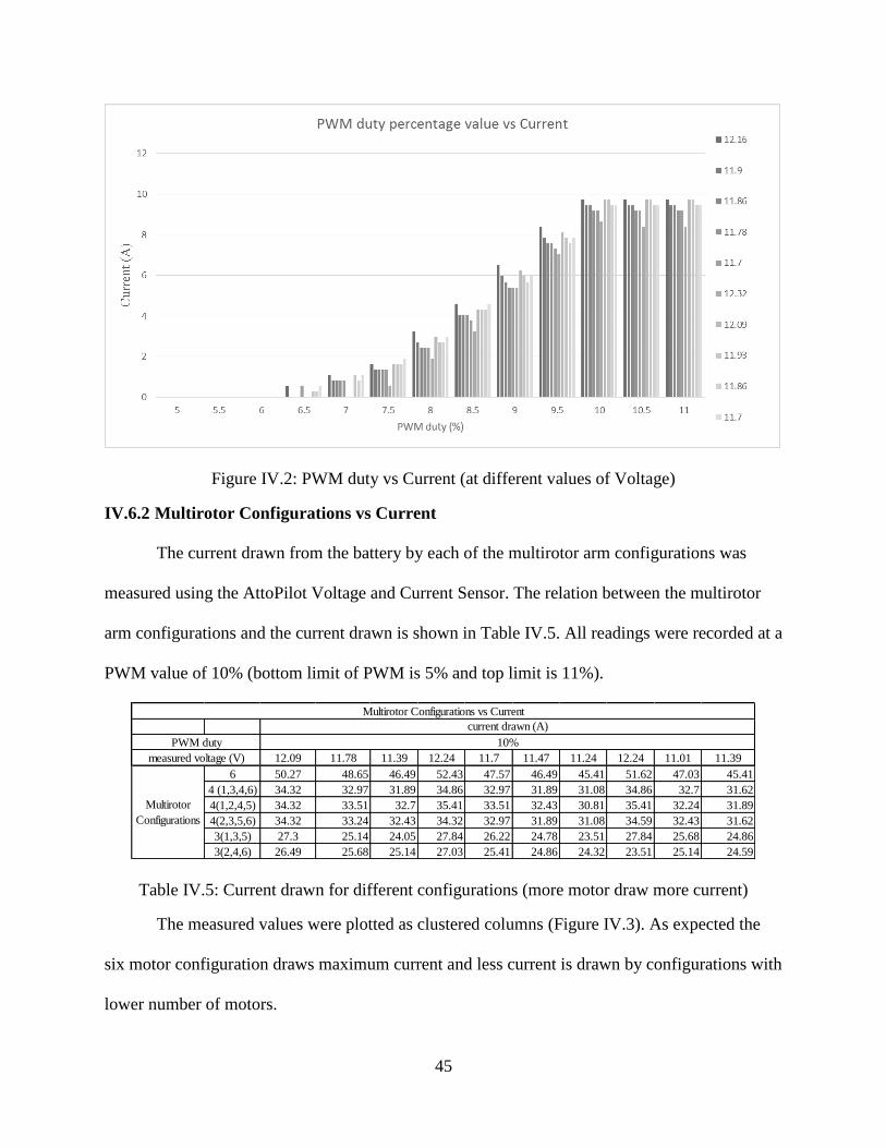
45
Figure IV.2: PWM duty vs Current (at different values of Voltage)
IV.6.2 Multirotor Configurations vs Current
The current drawn from the battery by each of the multirotor arm configurations was
measured using the AttoPilot Voltage and Current Sensor. The relation between the multirotor
arm configurations and the current drawn is shown in Table IV.5. All readings were recorded at a
PWM value of 10% (bottom limit of PWM is 5% and top limit is 11%).
Table IV.5: Current drawn for different configurations (more motor draw more current)
The measured values were plotted as clustered columns (Figure IV.3). As expected the
six motor configuration draws maximum current and less current is drawn by configurations with
lower number of motors.
12.09 11.78 11.39 12.24 11.7 11.47 11.24 12.24 11.01 11.39
6 50.27 48.65 46.49 52.43 47.57 46.49 45.41 51.62 47.03 45.41
4 (1,3,4,6) 34.32 32.97 31.89 34.86 32.97 31.89 31.08 34.86 32.7 31.62
4(1,2,4,5) 34.32 33.51 32.7 35.41 33.51 32.43 30.81 35.41 32.24 31.89
4(2,3,5,6) 34.32 33.24 32.43 34.32 32.97 31.89 31.08 34.59 32.43 31.62
3(1,3,5) 27.3 25.14 24.05 27.84 26.22 24.78 23.51 27.84 25.68 24.86
3(2,4,6) 26.49 25.68 25.14 27.03 25.41 24.86 24.32 23.51 25.14 24.59
Multirotor Configurations vs Current
Multirotor
Configurations
PWM duty
measured voltage (V)
current drawn (A)
10%
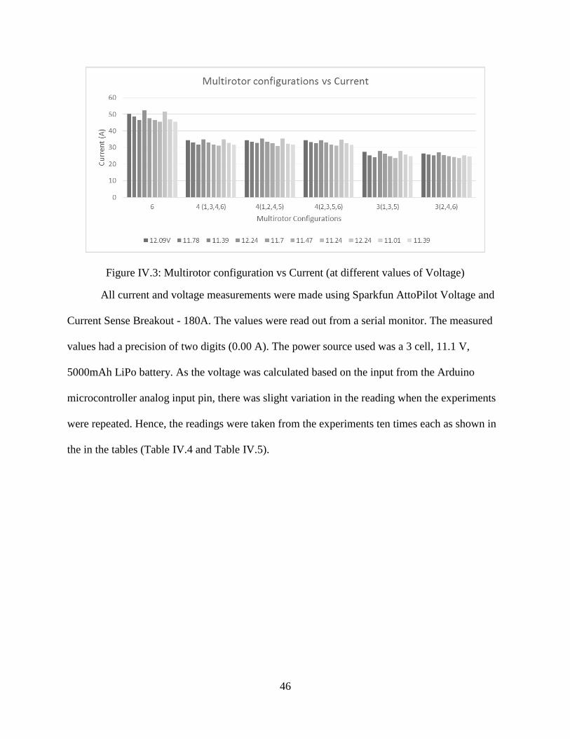
46
Figure IV.3: Multirotor configuration vs Current (at different values of Voltage)
All current and voltage measurements were made using Sparkfun AttoPilot Voltage and
Current Sense Breakout - 180A. The values were read out from a serial monitor. The measured
values had a precision of two digits (0.00 A). The power source used was a 3 cell, 11.1 V,
5000mAh LiPo battery. As the voltage was calculated based on the input from the Arduino
microcontroller analog input pin, there was slight variation in the reading when the experiments
were repeated. Hence, the readings were taken from the experiments ten times each as shown in
the in the tables (Table IV.4 and Table IV.5).
47
Chapter V Conclusion and Future Work
V.1 Conclusion
In this study a hardware/software adaptive multirotor controller platform was designed
and developed. The design was targeted on the processing system and FPGA fabric combination
of Xilinx Zynq System on Chip. FPGA runtime partial reconfigurations technology was used to
make the platform adapt different multirotor arm configurations. The design was tested on a
ZedBoard, the Zynq System on Chip prototyping board. The FPGA resource utilization of
different designs were recorded. A PWM signal generator was implemented as a hardware
module to drive the motors. The current drawn by a motor with respect to the PWM duty cycle
was recorded. PID control algorithm was implemented in software to perform single axis
balancing of a various arm configurations of the multirotor. The multirotor arm configuration
adaptivity was tested along with the PID algorithm.
The multirotor used for tests (XAircraft DIY HEXA) had six motors arranged in a
conventional hexacopter configuration. Hence the yaw angular momentum was balanced only for
the multirotor arm configuration where all six arms were used. For other configurations the yaw
angular momentum was not zero most of the time. It did not affect the single axis balancing to a
great extent as the multirotor was mounted without freedom to turn on its yaw axis. In future
developments a possible solution to balance the net yaw angular momentum of any multirotor
arm configuration is to use two motors with opposite spin on each arm. One motor should point
up and one motor should point down. The net angular momentum of each arm should be then
balanced. Hence, a combination of any number of multirotor arms should keep the net yaw
angular momentum balanced.

48
The adaptive multirotor platform was developed with a three phase design process. First,
as a base case an adaptive multirotor platform was designed without using partial hardware
reconfiguration technology. The seven different multirotor arm configurations were added as
hardware sub-modules. This design gave us an understanding of the working of a simple
adaptive platform which can switch between different multirotor arm configurations. Then
FPGA runtime partial reconfiguration technology was added to the design. Therefore hardware
implementation of one of the seven multirotor arm configurations had to be configured in the
FPGA at a time. The hardware modules for the seven different configurations were stored as
partial bit streams on the SD card. The partial bit streams were transferred into the reconfigurable
hardware partition as needed. In the final design, hardware modules for interfacing gyro sensor
to the existing system was added. PID control algorithm was implemented on the software side
to perform single axis balancing of the multirotor.
The runtime partial reconfiguration of multirotor control modules was tested
successfully. In this study the primary function of control modules was PWM generation
depending upon duty percentage values set from the software. Hence, the time taken to switch
the system from one configuration to other was negligible. The switching process has to be
optimized to ensure safety of equipment. It needs more research to implement an efficient
switching protocol. The single axis balancing of the multirotor with runtime switching of
multirotor arm configurations was not perfect. This is because of imperfections in the
experimental setup and because of signal noise in the gyro sensor due to vibration. In addition
the PID constants were tuned without mathematically modelling the multirotor controller. The
experimental setup has to be improved for better results in the future. Mathematical modelling of
the system is also need to be developed for implementing an effective adaptive controller.

49
V.2 Potential Applications
The adaptive multirotor controller platform has many potential applications. It needs to
be studied thoroughly to understand its strengths and limitations. An application of this type of
controller will be multirotors used for object delivery and retrieval [7]. If this technology is
developed further the arm configuration of the multirotor can be switched depending upon the
presence and absence of a load.
One hypothetical application for this study is autonomous configuration adaptivity. It was
not tested experimentally as part of this study. However, we believe this might be one possible
future application for this study. It is briefly described below.
We know the relation between the type of multirotor arm configurations and the
maximum current drawn from the battery (Table IV.5). Assume that we are using a 5000 mAh
battery. It means that theoretically the battery can discharge 5 Amperes for 60 minutes.
Depending upon this we can theoretically estimate the operational duration of a multirotor arm
configuration. If a configuration draws 50 Amperes of current, theoretically the battery can
power it for 10 minutes. Taking the average current value for each configuration from the table
we can theoretically estimate average operational time for each configuration. Table V.1 is
constructed based on an assumption that the battery is operated for the time duration listed.
However, the most of electronic speed controllers used in multirotors will cut off the battery if its
voltage drops below the limit for safe operation.
Table V.1: Theoretical estimation of operation time
(within the context of our hypothetical example)
MultirotorConfigurations Average Current (A) Battery rating (mAh) Estimated duration of operation (minutes)
6 48.137 5000 6.23
4 (1,3,4,6) 32.916 5000 9.11
4(1,2,4,5) 33.223 5000 9.03
4(2,3,5,6) 32.889 5000 9.12
3(1,3,5) 25.722 5000 11.66
3(2,4,6) 25.217 5000 11.90
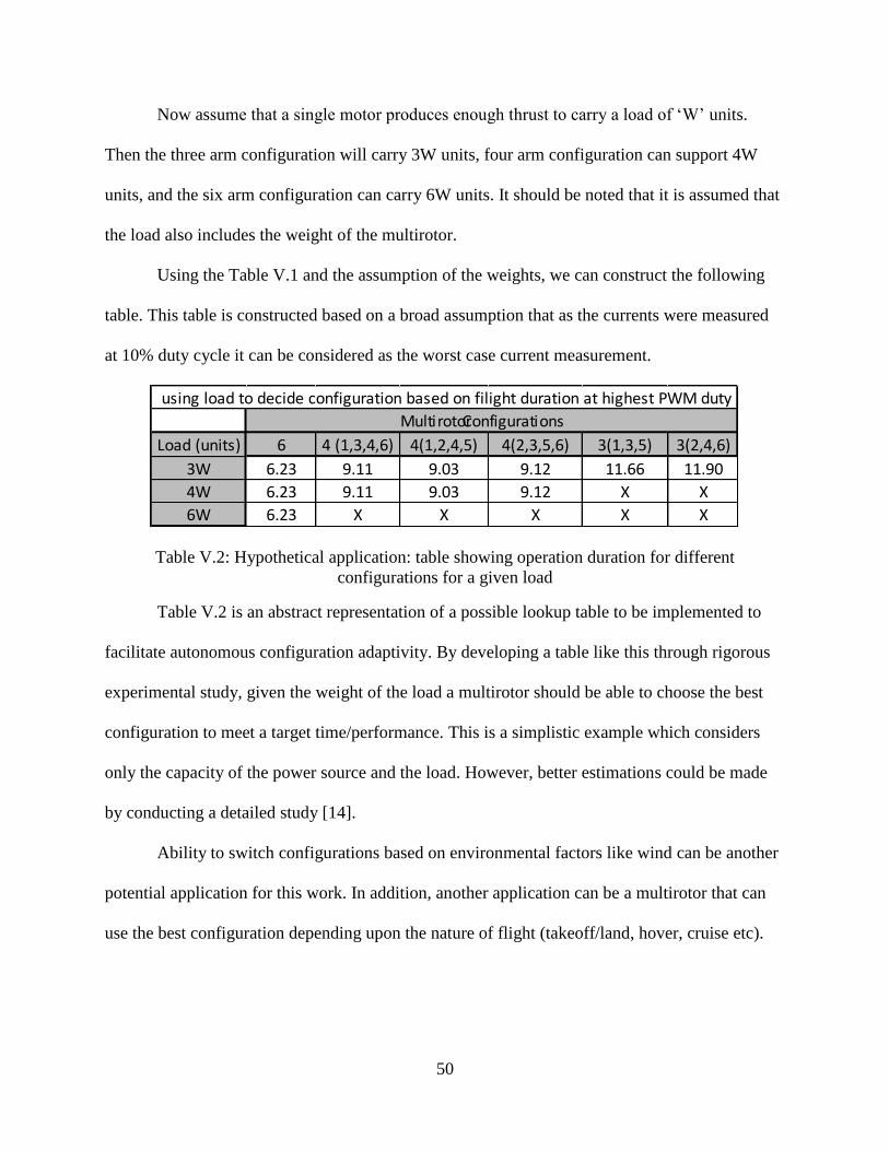
50
Now assume that a single motor produces enough thrust to carry a load of ‘W’ units.
Then the three arm configuration will carry 3W units, four arm configuration can support 4W
units, and the six arm configuration can carry 6W units. It should be noted that it is assumed that
the load also includes the weight of the multirotor.
Using the Table V.1 and the assumption of the weights, we can construct the following
table. This table is constructed based on a broad assumption that as the currents were measured
at 10% duty cycle it can be considered as the worst case current measurement.
Table V.2: Hypothetical application: table showing operation duration for different
configurations for a given load
Table V.2 is an abstract representation of a possible lookup table to be implemented to
facilitate autonomous configuration adaptivity. By developing a table like this through rigorous
experimental study, given the weight of the load a multirotor should be able to choose the best
configuration to meet a target time/performance. This is a simplistic example which considers
only the capacity of the power source and the load. However, better estimations could be made
by conducting a detailed study [14].
Ability to switch configurations based on environmental factors like wind can be another
potential application for this work. In addition, another application can be a multirotor that can
use the best configuration depending upon the nature of flight (takeoff/land, hover, cruise etc).
Load (units) 6 4 (1,3,4,6) 4(1,2,4,5) 4(2,3,5,6) 3(1,3,5) 3(2,4,6)
3W 6.23 9.11 9.03 9.12 11.66 11.90
4W 6.23 9.11 9.03 9.12 X X
6W 6.23 X X X X X
MultirotorConfigurations
using load to decide configuration based on filight duration at highest PWM duty
51
V.3 Future work
This work is in its initial state. There are opportunities to improve the current system as
well as to add more functionalities to the system. Three ways to improve the current system are
briefly explained below.
V.3.1 Multiplexed Dual Reconfigurable Partitions
In the current implementation of the adaptive multirotor controller there is only one
reconfigurable partition. The reconfigurable partition is where various control modules are
configured. When the multirotor needs to change its current arm configuration, it reconfigures
the reconfigurable partition using the new partial bit stream. There is a slight delay in this
process. This delay will increase in the future as the reconfiguration modules become bigger in
size when more functionality is moved to the hardware side from the software side. The
multirotor controller will be in a floating state during the reconfiguration. Hence, we need to
redefine the reconfiguration process to avoid the floating state.
One potential solution is the use of two identical reconfigurable partitions under the
control of a supervisor module [22]. The two reconfigurable partitions can be configured as
control modules using partial bit streams. However, only one of the reconfigurable partitions will
be active at a time. When the multirotor need to change its configuration the reconfigurable
module which is currently inactive is configured with the new partial bit stream. Once the
reconfiguration is complete and the reconfigurable partition is ready, the supervisor will make
the reconfigurable partition active and the other one is made inactive. The new configuration
takes effect only when the partial reconfiguration is complete and the reconfigurable partition is
ready. Hence the occurrence of a floating state can be prevented by implementing two identical
reconfigurable partitions controlled by a supervisor.
52
V.3.2 User Input from a Radio/Bluetooth Controller
One of the key functions that needs to be implemented on the system is user input
processing. Radio controllers are a popular multirotor control device. A Bluetooth based
controller will be also effective for low range indoor experimental work. A Bluetooth based
controller will be cheaper compared to a radio transmitter. A simple user interface can be
developed as a smart phone application. In addition a Bluetooth based controller will help us
setup software control interfaces (apps) on multiple mobile devices. The Bluetooth peripheral
modification module from Digilent Inc will be ideal for implementing a Bluetooth controller.
An ideal controller for the adaptive controller should have at least five channels. Four
channels to be used to control throttle, roll, pitch, and yaw of the multirotor. The fifth channel
can be used as a control input to trigger multirotor arm reconfiguration. The fifth channel can
have multiple discrete signal levels to select different multirotor arm configurations.
V.3.3 Mathematical Modeling of Multirotor
Developing a mathematical model of the multirotor system under development will be
necessary to implement a PID control algorithm effectively. The future version of the multirotor
under development can have up to 12 motors. It is necessary to have an accurate understanding
of the dynamics of the multirotor. Adjustments on the software side such as tuning of PID
control algorithm, calculating offsets for input/output values etc. can be done better with a
mathematical model. In addition, control modules for different multirotor parameters like pitch,
yaw, altitude etc. are also needed. Further development also need to incorporate an inertial
measurement unit (IMU) which combines a gyroscope and an accelerometer. The adaptive
controller system has to go through multiple design iterations before it can takeoff, hover, cruise
and land safely.
53
Bibliography
1. d'Oleire-Oltmanns, S., Marzolff, I., Peter, K., & Ries, J. (2012). Unmanned Aerial
Vehicle (UAV) for Monitoring Soil Erosion in Morocco. Remote Sensing, 4(12), 3390-
3416. doi:10.3390/rs4113390
2. Learn.sparkfun.com,. (2015). Motors and Selecting the Right One - learn.sparkfun.com.
Retrieved 6 July 2015, from https://learn.sparkfun.com/tutorials/motors-and-selecting-
the-right-one?_ga=1.34767073.1527219636.1432137882
3. Learn.sparkfun.com,. (2015). Battery Technologies - learn.sparkfun.com. Retrieved 6
July 2015, from https://learn.sparkfun.com/tutorials/battery-
technologies?_ga=1.235593793.1527219636.1432137882%23lithium-polymer
4. Phenoxlab.com,. (2015). Phenox | Phenox Lab. Retrieved 6 July 2015, from
http://phenoxlab.com/?page_id=296
5. Fogelberg, J. (2013). Navigation and Autonomous Control of a Hexacopter in Indoor
Environments (Msc). Lund University.
6. Chaimowicz, L., & Kumar, V. (2007). Aerial Shepherds: Coordination among UAVs and
Swarms of Robots. Distributed Autonomous Robotic Systems 6, 243-252.
doi:10.1007/978-4-431-35873-2_24
7. Amazon.com,. (2015). Amazon Prime Air. Retrieved 6 July 2015, from
http://www.amazon.com/b?node=8037720011
8. E-volo.com,. (2015). e-volo. Retrieved 5 July 2015, from http://www.e-volo.com/
9. Hover-bike.com,. (2015). MA Hoverbike. Retrieved 5 July 2015, from http://www.hover-
bike.com/MA/
10. Maxfield, C. (2008). FPGAs: Instant Access. Amsterdam: Newnes.
11. Norris, D. (2014). Build your own quadcopter. New York: McGraw-Hill Education.
12. Crockett, L., Elliot, R., Enderwitz, M., & Stewart, R. (2014). The Zynq Book: Embedded
Processing with the ARM Cortex-A9 on the Xilinx Zynq-7000 all Programmable SoC.
Strathclyde Academic Media.
13. Partial Reconfiguration User Guide (14.5). (2013) (14th ed.). Retrieved from
http://www.xilinx.com/support/documentation/sw_manuals/xilinx14_7/ug702.pdf
14. D'Andrea, R. (2014). Guest Editorial Can Drones Deliver?. IEEE Trans. Automat. Sci.
Eng., 11(3), 647-648. doi:10.1109/tase.2014.2326952
54
15. T G Zhou, T., T X Zhou, D., & H B Zhou, A. (2014). Unmanned drone, robot system for
delivering mail, goods, humanoid security, crisis negotiation, mobile payments, smart
humanoid mailbox and wearable personal exoskeleton heavy load flying machine. USA.
16. Grc.nasa.gov,. (2015). Aircraft Rotations. Retrieved 6 July 2015, from
https://www.grc.nasa.gov/www/k-12/airplane/rotations.html
17. Lewis, J. (2014). Feedback Control Systems Demystified: Volume 1 Designing PID
Controllers. Surber Press.
18. ZedBoard (Zynq™Evaluation and Development) Hardware User’s Guide. (2012) (1st
ed.). Retrieved from http://zedboard.org/sites/default/files/ZedBoard_HW_UG_v1_1.pdf
19. Delahaye, J., Gogniat, G., Roland, C., & Bomel, P. (2004). Software Radio and Dynamic
Reconfiguration on a DSP/FPGA platform. Frequenz, 58(5-6).
doi:10.1515/freq.2004.58.5-6.152
20. Lackey, R., & Upmal, D. (1995). Speakeasy: the military software radio. IEEE
Communications Magazine, 33(5), 56-61. doi:10.1109/35.392998
21. Bhandari, S., Subbaraman, S., & Pujari, S. (2010). Power Reduction in Embedded
System on FPGA Using on the Fly Partial Reconfiguration. 2010 International
Symposium On Electronic System Design. doi:10.1109/ised.2010.23
22. Danne, K., Bobda, C., & Kalte, H. (2003). Increasing Efficiency by Partial Hardware
Reconfiguration: Case Study of a Multi-Controller System. In International Conference
on Engineering of Reconfigurable Systems and Algorithms. Las Vegas, Nevada, USA.
23. Ganesh Nayak, N. (2013). Accelerated Computation using Runtime Partial
Reconfiguration (Master's). University of Stuttgart.
24. Digilentinc.com,. (2015). Digilent Inc. - Digital Design Engineer's Source. Retrieved 6
July 2015, from
https://www.digilentinc.com/Products/Detail.cfm?NavPath=2,401,937&Prod=PMOD-
GYRO
25. Compact DC Voltage and Current Sense PCB with Analog Output. (2011) (1st ed.).
Retrieved from
http://cdn.sparkfun.com/datasheets/Sensors/Current/DC%20Voltage%20and%20Current
%20Sense%20PCB%20with%20Analog%20Output.pdf
26. Haskell, R., & Hanna, D. (2009). Digital design using digilent FPGA boards (2nd ed.,
pp. 185-190). Rochester Hills, MI: Learning by Example.