Embed Size (px)
Citation preview

Adaptive Flux-Weakening Controller for IPMSM Drives
Silverio BOLOGNANI1, Sandro CALLIGARO2, Roberto PETRELLA2
1 Department of Electrical Engineering (DIE), University of Padova (Italy) 2 Department of Electrical, Management and Mechanical Engineering (DIEGM), University of Udine (Italy)
[email protected], [email protected], [email protected]
Abstract – Voltage feed-back flux-weakening (FW) control scheme for vector-controlled Interior Permanent Magnet Synchronous Motor (IPMSM) drive systems is considered in this paper. The voltage controller is based on the difference between the amplitude of the reference voltage space vector and a proper limit value, related to the feeding inverter limitations, and adopts the phase angle of reference current space vector as the control variable. A novel theoretical analysis of the overall dynamics of the voltage control loop is carried out, also taking into account non-linear effects and discrete-time implementation issues. The design of the controller can therefore be optimized for each operating condition by an adaptive approach, allowing to define stability properties and to maximize bandwidth of the voltage control loop. Maximization of the dynamical performance provides the main advantage of the proposal, i.e. allows a lower voltage (control) margin to be considered with respect to standard approaches, leading to a higher torque and system efficiency and/or a reduced value of the dc-bus capacitance. A motor drive system for home appliances is considered as a test bench to prove the effectiveness and importance of the proposal.
I. INTRODUCTION
Interior Permanent Magnet Synchronous Motors (IPMSM) are often considered for such applications where wide constant-power speed range is required. Optimized machine control is obtained both within the base speed range (e.g. with maximum-torque-per-ampere (MTPA) control) and in flux-weakening operations by means of proper control of direct and quadrature components of the stator current space vector,[1]-[4].
In flux-weakening region motor terminal voltage is controlled to a proper value, related to the feeding inverter limitation, by employing feed-forward, feed-back or mixed control approaches, [4]. Design of the flux-weakening controller aims at guaranteeing the maximum available voltage exploitation and stability of the loop, [5]-[9].
When a very high speed condition is considered, some effects related to the non-linear behavior of the voltage control loop (e.g. also related to cross-coupling effects) and to discrete time implementation become extremely important, [10], and
can lead to instability of the controller or to a non optimized bandwidth of the loop. Unfortunately no analytical development can be found in literature allowing the optimized design of the flux-weakening controller and a manual tuning is normally considered in actual drive systems.
A novel theoretical analysis of the overall dynamics of the voltage control loop is proposed in this paper and allows the design of the controller to be optimized for each operating condition. Therefore stability properties and maximization of the loop bandwidth can be guaranteed, e.g. by a proper dynamical adaptation of the voltage control loop regulator gain. This last feature provides the main advantage of the presented approach, i.e. allows a lower voltage (control) margin to be considered with respect to standard approaches based on a fixed design of voltage controller, definitively leading to a higher torque and system efficiency and/or a reduced value of the dc-bus capacitance. A motor drive system for home appliances is considered as a test bench for both simulation and experimental investigations. Obtained results prove the effectiveness and importance of the proposal.
II. FEEDBACK FLUX-WEAKENING CONTROL SCHEME
The considered drive control scheme implementing the proposed flux-weakening strategy is shown in Fig. 1. Flux-weakening is based on a proper choice of the current space vector (both angle and amplitude ) based on the direct feed-back control of the amplitude of the reference voltage space vector | | and rotor speed , as shown in Fig. 2. The difference between the amplitude of the reference voltage and a proper limit value, related to the feeding inverter limitations, is controlled to zero by varying the phase angle of the reference current space vector.
This solution can be analytically proved to provide important advantages with respect to classical approaches based on the variation of direct and/or quadrature current components, [4] (details are also provided in the next sections).
Current space vector angle is saturated to stay in the range
MTPA ; , where MTPA is the value assuring (until possible) MTPA control. Anti wind-up action ensures a smooth transition from MTPA to flux-weakening operations. Bottom

limitation imposed to the MTPA angle automatically activates voltage regulation only when needed (i.e. when the voltage reference is exceeded). A trade-off between the need for preserving a voltage margin with respect to the inverter limitation (i.e. avoiding saturation) for current control stability by one side and exploiting full power capabilities by the other thus exists also with the considered scheme.
III. ANALYSIS OF THE VOLTAGE CONTROL LOOP
Aim of this section is to study the static and dynamical behavior of the voltage control loop adopted in the flux-weakening operating region. The results can be adopted for the optimized design of the controller for each speed operating condition. Therefore stability properties can be specified and maximization of the bandwidth of the loop obtained through a proper choice of the voltage control loop transfer function.
The conventional voltage equation of IPM motor in the reference frame synchronous with permanent magnet flux-linkage is considered, i.e.:
(1)
where , and are voltage, current and permanent magnet flux linkage vectors, i.e.
, , Λ
0 (2)
and matrices and are related to motor synchronous inductances, i.e.:
00 , 0 1
1 0,
00
(3)
Electromagnetic torque is therefore:
32
Λ (4)
where is the number of pole-pairs. In this analysis, an IPM motor (parameters are reported in the Appendix) is considered theoretically allowing infinite speed in deep field-weakening conditions, i.e. the voltage ellipse centre is inside the rated current circle, as shown in Fig. 3.
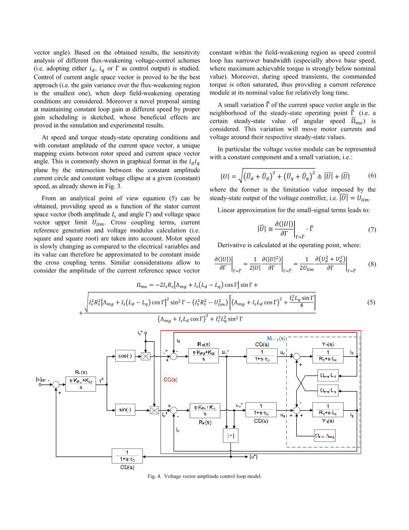
The voltage control loop adopted in the flux-weakening operating region can be represented by means of the block diagram shown in Fig. 4. A first order approximation of control delays taking into account the discrete time implementation and pulse-width-modulation have been considered both in the forward loop and in the feedback loop. Electrical angular speed Ω is considered at steady-state condition, as the dynamical behavior of the electrical quantities is analyzed. Voltage regulator , current regulators and , control delays and motor
model Ω (matrix) transfer functions are shown in the diagram. Λ is the permanent magnet flux-linkage, , and are phase resistance and synchronous inductances respectively. The equivalent analytical model is highly non-linear due to the presence of angular speed dependent terms (i.e. back-electromotive force) as well as non-linear terms (both transcendent and modulus functions).
A. Steady-state (static) small-signal analysis Static gain of the transfer function linking the variation of
the stator voltage amplitude as a consequence of the variation of the current space vector angle will be calculated for different values of the steady-state condition of speed (i.e. current space
Fig. 1. IPMSM drive control scheme.
Fig. 2. Flux-weakening voltage amplitude control.
Fig. 3. Control trajectories and limit loci in the plane.
vector angle). Based on the obtained results, the sensitivity analysis of different flux-weakening voltage-control schemes (i.e. adopting either , or Γ as control output) is studied. Control of current angle space vector is proved to be the best approach (i.e. the gain variance over the flux-weakening region is the smallest one), when deep field-weakening operating conditions are considered. Moreover a novel proposal aiming at maintaining constant loop gain at different speed by proper gain scheduling is sketched, whose beneficial effects are proved in the simulation and experimental results.
At speed and torque steady-state operating conditions and with constant amplitude of the current space vector, a unique mapping exists between rotor speed and current space vector angle. This is commonly shown in graphical format in the plane by the intersection between the constant amplitude current circle and constant voltage ellipse at a given (constant) speed, as already shown in Fig. 3.
From an analytical point of view equation (5) can be obtained, providing speed as a function of the stator current space vector (both amplitude and angle Γ) and voltage space vector upper limit . Cross coupling terms, current reference generation and voltage modulus calculation (i.e. square and square root) are taken into account. Motor speed is slowly changing as compared to the electrical variables and its value can therefore be approximated to be constant inside the cross coupling terms. Similar considerations allow to consider the amplitude of the current reference space vector
constant within the field-weakening region as speed control loop has narrower bandwidth (especially above base speed, where maximum achievable torque is strongly below nominal value). Moreover, during speed transients, the commanded torque is often saturated, thus providing a current reference module at its nominal value for relatively long time.
A small variation Γ of the current space vector angle in the neighborhood of the steady-state operating point Γ (i.e. a certain steady-state value of angular speed Ω ) is considered. This variation will move motor currents and voltage around their respective steady-state values.
In particular the voltage vector module can be represented with a constant component and a small variation, i.e.:
| | | | | | (6)
where the former is the limitation value imposed by the steady-state output of the voltage controller, i.e. | | .
Linear approximation for the small-signal terms leads to:
| || |
Γ· Γ (7)
Derivative is calculated at the operating point, where:
| |
Γ1
2| || |
Γ1
2 Γ (8)
Ω 2 Λ cos Γ sin Γ
Λ cos Γ sin Γ Λ cos Γsin Γ
4
Λ cos Γ sin Γ
(5)
Fig. 4. Voltage vector amplitude control loop model.

Substitution of steady-state voltage expressions obtained from motor model, static gain can easily be calculated, i.e.:
| |
Γ1
22 Λ Ω Ω cos Γ sin Γ
· cos Γ Ω sin Γ2 Ω cos Γ sin Γ
· cos Γ Ω sin Γ
(9)
Analysis of (9) for each steady-state value of angular speed (i.e. each value of Γ) provides sensitivity of the voltage control loop to a (small) variation of the current space vector angle.
Similar relations can be obtained if the output of the voltage regulator is in turn considered to be the direct or quadrature component of stator current reference. Plots of different sensitivity functions normalized against their maximum values in the considered range are shown in Fig. 5. The situation is very different among the three control choices, i.e. heavy gain variation occurs in the deep flux-weakening region. This is especially true when using a scheme in which -axis current is the voltage regulator output. This was expected since circular current trajectory (constant amplitude) has a high slope, for angle values near to . The results of this analysis are true for the actual motor considered in this paper (i.e. having a high reluctance torque component).
The minimum variation of the static gain occurs adopting the current space vector angle as the control output. Even in that case, however, the voltage control loop static gain exhibit large variations over the whole speed operating range, thus suggesting an adaptive voltage controller in order to provide a globally optimized bandwidth. The dynamical analysis of the voltage control loop will first be carried out in the next section in order to confirm that statement and suggest possible solutions.
Finally, if (9) is re-arranged as a function of both direct and quadrature currents (i.e. with variable I and Γ), the behaviour of the static gain in the whole dq plane is obtained, as shown in Fig. 6. The rated current limit locus (blue circular trace) and the MTPA trajectory (red trace) are also shown for completeness. One can notice that the static gain is also a function of the current space vector amplitude and the maximum-to-minimum ratio at about a half of the rated current is even higher than at rated current. This proves that gain adaptation of the voltage controller is needed even in the case a lower limitation on the current value is adopted.
B. Dynamical analysis Linearization of the voltage control loop shown in Fig. 4 in
the neighborhood of a certain operating condition allows to study the dynamical behavior in the Laplace domain as a function of frequency by means of the open-loop transfer function, comprising the motor model, currents regulation loop, control and inverter delays, voltage modulus (feedback) calculation, voltage regulation and reference current generation.
If the motor electrical model (in the reference frame) at fixed speed Ω is considered for small-signal analysis, a linear MIMO (multiple input multiple output, i.e. two-input two-output) dynamical system is obtained, with voltages as inputs and currents as outputs. In this way, motor model can be seen as a 2 2 Laplace transfer function matrix Ω :
Ω
(10)
1 Ω Ω
Ω
1 Ω Ω
Ω
1 Ω Ω
1 Ω Ω
(11)
, are the phase admittances, i.e.:
Fig. 5. Normalized static gains (gain values to their maximum ratio)
at rated amplitude of the current space vector.
Fig. 6. Static gain as a function of direct and quadrature current.
1,
1 (12)
Commanded voltage vector can be expressed as:
00
(13)
where and are the current regulators transfer
functions. Motor actual voltage is a delayed version of commanded voltage, as PWM cycle and calculation delay of the digital control subsystem are taken into account, i.e.:
11
(14)
The first order Padé approximation of the time delay is considered, with time constant 3 2⁄ · C, [10]. Substitution of (13) into (14) and then into (10), yields the current closed-loop transfer function (actual to reference), i.e.:
Ω
· Ω
(15)
where is the 2 order identity matrix.
Equation (13) can therefore be re-arranged as:
(16)
Reference currents can be expressed as a function of reference current space vector angle through an approximated linear model starting from non-linear sine and cosine functions shown in Fig. 4, i.e.:
sin Γcos Γ
(17)
Upper-case over-lined symbols represent the operating point values. Modulus of the voltage space vector can be computed by a linear approximation through partial derivatives, i.e.:
| |0
0 (18)
Substitution of (16) into (18) and considering (17) allows to obtain a comprehensive transfer function linking reference current vector angle to voltage amplitude | |, i.e.:
| | 0
0
sin Γcos Γ
(19)
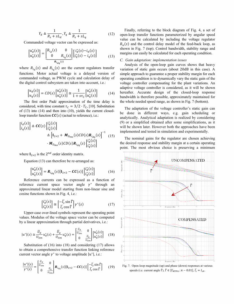
Finally, referring to the block diagram of Fig. 4, a set of open-loop transfer functions parameterized by angular speed value can be calculated by including the voltage regulator
and the control delay model of the feed-back loop, as shown in Fig. 7 (top). Control bandwidth, stability range and margins can easily be calculated for each operating condition.
C. Gain adaptation: implementation issues Analysis of the open-loop gain curves shows that heavy
variation of static gain occurs (about 20dB in this case). A simple approach to guarantee a proper stability margin for each operating condition is to dynamically vary the static gain of the voltage controller compensating for the plant variations. An adaptive voltage controller is considered, as it will be shown hereafter. Accurate design of the closed-loop response bandwidth is therefore possible, approximately maintained for the whole needed speed range, as shown in Fig. 7 (bottom).
The adaptation of the voltage controller’s static gain can be done in different ways, e.g. gain scheduling or analytically. Analytical adaptation is realized by considering (9) or a simplified obtained after some simplifications, as it will be shown later. However both the approaches have been implemented and tested in simulation and experimentally.
The nominal gains for the regulator are chosen achieving the desired response and stability margin at a certain operating point. The most obvious choice is preserving a minimum
Fig. 7. Open-loop magnitude (up) and phase (down) responses at various
speeds (i.e. current angle Γ), Γ ΓMTPA ; π 0.01 , .

stability margin (i.e. maximizing the gains) at the most critical conditions, i.e. at the maximum operating speed and maximum current magnitude. This can be achieved analytically, based upon the previously depicted dynamics model, or by empirical tuning on the real system.
The gain adaptation is then implemented as a multiplicative factor applied to both integral and proportional values of the voltage regulator. The scaling value is obtained by dividing the static gain at the nominal condition (i.e. the one calculated off-line at the tuning point) by the calculated value of the static gain updated for the actual operating condition:
| |Γ
| | (20)
Gain analysis above developed leads to a long and non trivial expressions, also involving trigonometric calculations. However, further manipulation on the static gain equation (9) can significantly simplify the gain adaptation procedure, by introducing electrical quantities which are already known from the current control loop (synchronous voltages and currents).
In fact, from (8), the derivative is the sum of two terms
| |
Γ1
2 Γ Γ (21)
which can be further expressed as
| |
Γ1
22
Γ2
Γ (22)
By considering the expressions for the steady-state voltage
Ω
Ω Ω Λ (23)
the last equation can be expanded in
| |
Γ1
22 sin Γ Ω cos Γ
2 cos Γ Ω sin Γ (24)
leading to:
| |
Γ1
Ω
Ω (25)
Indeed both steady-state and transient conditions are here approximated by a sequence of quasi-steady-state points. Calculation of the adaptation factor (20) by using (25) is done on-line (i.e. at each sampling period, see Fig. 8), requiring only small calculation efforts. In fact only few product/sum operations on the values of current, speed and voltage are required, values already available to the vector controller.
IV. SIMULATION RESULTS
Reliability of the proposed analysis has initially been verified by comparing the results of a complete electro-mechanical dynamical model simulation of the drive system, including sampled-time control and inverter delay, and the linearized continuous-time analytical model discussed in the previous sections.
A simple validation is obtained by comparing the small-signal response to a square-wave voltage reference | | , as shown in Fig. 9, at two different rotor speed conditions in the flux-weakening region, at rated current and with a certain design of the voltage loop controller. An optimal matching is
Fig. 8. Block diagram of the adaptation algorithm.
Fig. 9. Dynamic response to a square-wave voltage reference.
Fig. 10. Load torque disturbance rejection at 10000 (simulation).

obtained in both conditions but a nearly unstable behavior is present at very high speed, due to a reduced phase margin of the control loop, confirming the dynamical analysis of the previous section.
A comparison between fixed and gain scheduling voltage controllers (designed for the same maximum speed value of 22000 ) is shown in Fig. 10. A load torque step disturbance (low-pass filtered at 1 ) at steady-state and high-speed condition is applied and the response of the voltage control loop analyzed. The reference voltage has been chosen to be lower than the maximum allowable voltage of the inverter in order to study the behavior of the controller in non saturated conditions. As shown in the zoomed boxes the peak voltage reached during load torque removal is much lower when gain scheduling controller is considered, thus confirming the reliability of the proposed analysis and the effectiveness of the gain adaptation. Optimization of voltage control loop allows therefore to increase the voltage limiting value and to maximize bus voltage exploitation.
V. EXPERIMENTAL RESULTS
A prototype motor drive system for home appliances is considered as a test bench to prove the effectiveness of the proposal. The results shown hereafter are mainly intended to prove that optimal design of voltage regulation loop is possible and provide better dynamical response for each speed operating condition, as demonstrated by the analytical developments of previous sections. In all the results on-line adaptation of voltage regulator’s gains is implemented. Maximization of the bandwidth of the voltage regulation loop is therefore obtained in the whole flux-weakening range and a lower voltage (control) margin could be considered, especially at very high speed.
In the result of Fig. 11 a similar test to those of Fig. 10 is considered, showing that a good agreement is obtained between theoretical analysis, simulations and experiments. As in the results of Fig. 10 the reference voltage has been chosen to be lower than the maximum allowable voltage out of the inverter in order to study the behavior of the voltage controller in non saturated conditions. It should be noted that the experimental set-up does not allow a step torque disturbance generation as in the simulation results, since an induction motor drive is adopted as load in this case.
The design and optimization of the voltage regulator’s gains are done by considering the open-loop transfer function (magnitude and phase) at e.g., 10000 . Gain scheduling is considered for the voltage regulator in these experiments.
Referring to Fig. 11, when a lower value of the speed is commanded, i.e. 5000 , and voltage regulator’s gain is kept constant, a relatively high value of actual voltage overshoot is obtained as response to a sudden variation of load torque. As a higher gain margin is available at lower speed, voltage
Fig. 11. Load torque disturbance rejection at 5000
(experimental, voltage regulator operates in linear conditions).
Fig. 12. Load torque disturbance rejection at 5000 (experimental, gain
adaptation is off, voltage regulator operates in saturated conditions).
Fig. 13. Load torque disturbance rejection at 5000 (experimental, gain
adaptation is on, voltage regulator operates in saturated conditions).
regulator’s gain can be adapted (increased) consequently. Then the response of voltage regulation loop to the same load torque variation provides a lower dynamical error. Only one response for speed, current space vector phase and amplitude are shown in the figure as the difference between the two cases (i.e. with or without gain scheduling) is hardly appreciable.Another test in the same operating conditions, with gain scheduling activated and with a higher value of the voltage regulator’s gain (an increase of 50% is considered, i.e. about 3 ) provides instability, thus proving the reliability of the theoretical analysis.
In the results of Fig. 12 and Fig. 13 similar load torque disturbance tests at 5000 are considered, respectively without and with gain adaptation. Adaptation law coming from (20) and (25) is implemented in these cases, instead of gain scheduling. Moreover the difference with respect to the results of Fig. 11 refer to the voltage limitation value, that is now very close to the actual inverter’s limitation, i.e. the voltage regulator will operate in saturated conditions during transients.
The results show that the adaptation provides better overall results. Particularly one can notice that the speed undershoot is highly reduced and current control is maintained during the whole torque transient, definitively proving that higher voltage control bandwidth is attained with the proposed adaptive approach. This in turn means that a reduction of the voltage margin can be considered in the voltage control loop, thus providing higher torque for the same speed value.
VI. CONCLUSIONS
A novel static and dynamical analytical investigation of a feed-back voltage control loop for flux-weakening operation of IPM motor drives has been proposed. The analytical results prove that voltage control loop dynamics can be theoretically designed. This allows to guarantee stability and to maximize exploitation of the inverter bus voltage. A simple approach for on-line gain adaptation has been presented, based either on gain scheduling or on real-time calculation of the adaptation gain as a function of the motor operating condition. The obtained experimental results based prototype motor drive for home appliances prove that a lower voltage (control) margin can adopted with the proposed approach with respect to standard solutions based on a fixed design of voltage controller. This leads to a higher torque for each speed, i.e. higher system efficiency and/or a reduced value of the dc-bus capacitance.
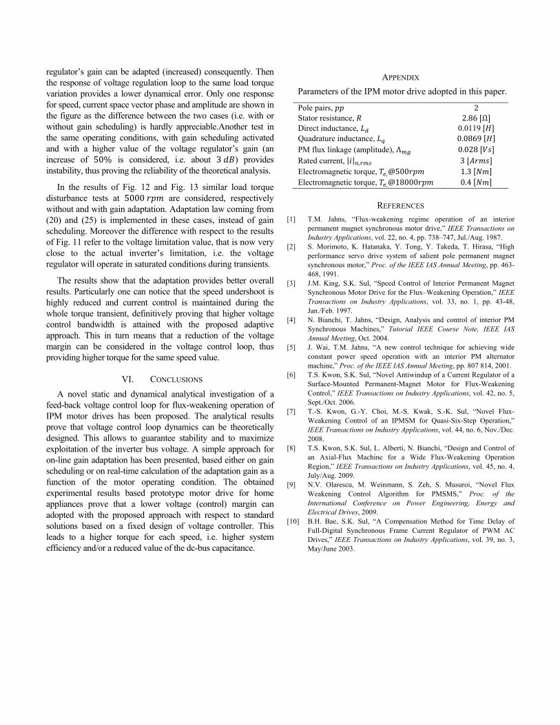
APPENDIX
Parameters of the IPM motor drive adopted in this paper.
Pole pairs, 2 Stator resistance, 2.86 Ω Direct inductance, 0.0119 Quadrature inductance, 0.0869 PM flux linkage (amplitude), Λ 0.028 Rated current, | | , 3 Electromagnetic torque, ,@500 1.3 Electromagnetic torque, ,@18000 0.4
REFERENCES
[1] T.M. Jahns, “Flux-weakening regime operation of an interior permanent magnet synchronous motor drive,” IEEE Transactions on Industry Applications, vol. 22, no. 4, pp. 738–747, Jul./Aug. 1987.
[2] S. Morimoto, K. Hatanaka, Y. Tong, Y. Takeda, T. Hirasa, “High performance servo drive system of salient pole permanent magnet synchronous motor,” Proc. of the IEEE IAS Annual Meeting, pp. 463- 468, 1991.
[3] J.M. King, S.K. Sul, “Speed Control of Interior Permanent Magnet Synchronous Motor Drive for the Flux–Weakening Operation,” IEEE Transactions on Industry Applications, vol. 33, no. 1, pp. 43-48, Jan./Feb. 1997.
[4] N. Bianchi, T. Jahns, “Design, Analysis and control of interior PM Synchronous Machines,” Tutorial IEEE Course Note, IEEE IAS Annual Meeting, Oct. 2004.
[5] J. Wai, T.M. Jahns, “A new control technique for achieving wide constant power speed operation with an interior PM alternator machine,” Proc. of the IEEE IAS Annual Meeting, pp. 807 814, 2001.
[6] T.S. Kwon, S.K. Sul, “Novel Antiwindup of a Current Regulator of a Surface-Mounted Permanent-Magnet Motor for Flux-Weakening Control,” IEEE Transactions on Industry Applications, vol. 42, no. 5, Sept./Oct. 2006.
[7] T.-S. Kwon, G.-Y. Choi, M.-S. Kwak, S.-K. Sul, “Novel Flux-Weakening Control of an IPMSM for Quasi-Six-Step Operation,” IEEE Transactions on Industry Applications, vol. 44, no. 6, Nov./Dec. 2008.
[8] T.S. Kwon, S.K. Sul, L. Alberti, N. Bianchi, “Design and Control of an Axial-Flux Machine for a Wide Flux-Weakening Operation Region,” IEEE Transactions on Industry Applications, vol. 45, no. 4, July/Aug. 2009.
[9] N.V. Olarescu, M. Weinmann, S. Zeh, S. Musuroi, “Novel Flux Weakening Control Algorithm for PMSMS,” Proc. of the International Conference on Power Engineering, Energy and Electrical Drives, 2009.
[10] B.H. Bae, S.K. Sul, “A Compensation Method for Time Delay of Full-Digital Synchronous Frame Current Regulator of PWM AC Drives,” IEEE Transactions on Industry Applications, vol. 39, no. 3, May/June 2003.


![Mechanically actuated variable flux IPMSM for EV and HEV ......summarised in a previous paper [8]. The outcome of the study found the optimum solution to be a mechanical variable flux](https://img.pdfslide.net/doc/110x75/603a4e667bf1f47706267096/mechanically-actuated-variable-flux-ipmsm-for-ev-and-hev-summarised-in-a.jpg)