Embed Size (px)
Citation preview

International Journal on Electrical Engineering and Informatics - Volume 7, Number 3, September 2015
Adaptive Neuro Fuzzy Inference System PID Controller for AVR System
Using SNR-PSO Optimization
Kamal Yavarian, Amir Mohammadian, and Farid Hashemi
Department of Electrical Engineering, Ardabil Branch, Islamic Azad University, Ardabil, Iran
Abstract: This paper presents an intelligent Proportional Integral Derivative (PID)
controller for Automatic Voltage Regulator (AVR) system using Adaptive Neuro Fuzzy
Inference System (ANFIS). In the proposed method, the PID controller parameters are
tuned off line by using combination of Signal to Noise Ratio (SNR) and Particle Swarm
Optimization (PSO) algorithm to minimize the cost function over a wide range of
operating condition. The optimal values of PID controller parameters obtained from
SNR-PSO algorithm for each considered operating condition are used to train ANFIS.
Therefore, the proposed techniques could online tune the PID controller parameters at
any other operating condition to improve the transient response of the system. In order
to evaluate the performance of the SNR-PSO PID controller, the results are compared
with the Genetic Algorithm (GA). Also, the performance of proposed intelligent PID
controller is compared with the robust SNR-PSO PID controller with fixed parameters.
The comparison shows the SNR-PSO based ANFIS controller is more efficiency than
robust PID controller.
Keywords: Controller, Automatic voltage regulator, Signal to noise ratio, Particle
swarm optimization, Adaptive neuro fuzzy inference system.
1. Introduction
Nowadays, economic and environmental constraints can lead to higher utilization of
existing plant, deferred expenditure on system reinforcement (and longer distance between
power plant and load center), with consequent erosion of stability margins. However, it is
necessary to ensure that adequate stability margins are maintained for the reliable power
supply. Multiple generators in a power station are connected to a common bus bar and each of
these generators has an Automatic Voltage Regulator (AVR) whose main objective is to
control the primary voltage. Due to system disturbances the electrical oscillations may occur
for a long time and might result in system instability. Hence effective control algorithms are
required to alleviate these issues. The AVR systems are used extensively in exciter control
system. The main objective of the AVR is to control the terminal voltage by adjusting the
generator exciter voltage. The AVR must keep track of the generator terminal voltage all the
time and under any load condition, working in order to keep the voltage within pre-established
limits [1]. In most modern systems, the AVR is a controller that senses the generator output
voltage (and sometimes the current) then initiates corrective action by changing the exciter
control in the desired direction. Nowadays, more than 90% control loops in industry are
Proportional-Integral-Derivative (PID) control. This is mainly due to the fact that PID
controller possesses robust performance to meet the global change of industry process, simple
structure to be easily understood by engineers, and easiness to design and implement. The PID
and its variations (P,PI,PD) still are widely applied in the motion control because of its simple
structure and robust performance in a wide range of operating conditions [2-6]. Unfortunately,
it has been quite difficult to tune properly the gains of PID controllers because many industrial
plants are often burdened with problems such as high order, time delays, and nonlinearities.
Therefore, when the search space complexity increases the exact algorithms can be slow to find
global optimum. Linear and nonlinear programming, brute force or exhaustive search and
divide and conquer methods are some of the exact optimization methods. Over the years,
several heuristic methods have been proposed for the tuning of PID controllers. These methods
have several advantages compared to other algorithms as follows: a) Heuristic algorithms are
Received: July 8th
, 2014. Accepted: September 9th
, 2015
DOI: 10.15676/ijeei.2015.7.3.3
394

generally easy to implement; b) They can be used efficiently in a multiprocessor environment;
c) They do not require the problem definition function to be continuous; d) They generally can
find optimal or near-optimal solutions [7-10]. The coefficients of the conventional PID
controller are not often properly tuned for the nonlinear plant with unpredictable parameter
variations. Hence, it is necessary to automatically tune the PID parameters with respect to
changes of the power system operating point and small disturbances. This paper presents the
adaptive design of AVR control scheme for synchronous generators that is capable of
providing satisfactory voltage control performance in the presence of unknown variations of
the power system operating conditions. In this paper, firstly in order to determine optimal
values of PID controller parameters for different operating condition one new combination of
heuristic algorithms is proposed. This proposed optimization method combines the features of
Signal to Noise Ratio (SNR) and Particle swarm optimization (PSO) algorithm in order to
improve the optimize operation. Finally the ANFIS based controller is trained with optimal
PID parameters obtained for each operating condition. Therefore, after make fuzzy inference
system when operating condition change PID coefficient controller change intelligently to
improve the transient response of the system.
This paper is organized as follows. Section II introduces the linearized Model of AVR system.
Section III presents hybrid SNR-PSO algorithm. In section IV, ANFIS is explained.
Methodology and Architecture of the proposed algorithm is presented in sections V and VI.
Section VII presents the simulation results to verify the effectiveness of the proposed technique
and, in the last section, conclusions are presented.
2. Linearized Model of AVR System
The aim of AVR control is to maintain the system voltage between limits by adjusting the
excitation of the machines. The automatic voltage regulator senses the difference between a
rectified voltage derived from the stator voltage and a reference voltage. This error signal is
amplified and fed to the excitation circuit. The change of excitation maintains the VAR balance
in the network. This method is also referred as Megawatt Volt Amp Reactive (MVAR) control
or Reactive-Voltage (QV) control [11-14].
A) PID Controller
The PID controller is used to improve the dynamic response as well as to reduce or eliminate
the steady-state error. The PID controller transfer function is:
SKS
KKsG d
ipPID )( (1)
The functionalities of PID controller include: (a) the proportional term provides an overall
control action proportional to the error signal through the all pass gain factor (b) The integral
term reduces steady-state errors through low-frequency compensation (c) The derivative term
improves transient response through high-frequency compensation.
B) Model of an AVR System
The role of an AVR is to hold the terminal voltage magnitude of a synchronous generator at
a specified level. A simple AVR system comprises four main components, namely amplifier,
exciter, generator, and sensor. For mathematical modeling and transfer function of the four
components, these components must be linearized, which takes into account the major time
constant and ignores the saturation or other nonlinearities. The reasonable transfer function of
these components may be represented, respectively, as follows [14-19].
• Amplifier model
The amplifier model is represented by a gain AK and a A time constant. The transfer
function is
395
Kamal Yavarian, et al.

A
AA
KG
1 (2)
Where the typical value of AK is in the range of [10, 400] and A is very small ranging from
0.02 to 0.1 s.
• Exciter model.
The transfer function of a modern exciter may be represented by a gain EK and a single time
constant E
E
EE
KG
1 (3)
Where the typical value of EK is in the range of [10, 400] and the time constant E ranges
from 0.5 to 1.0 s.
• Generator model
The transfer function relating the generator terminal voltage to its field voltage can be
represented by a gain GK and a time constant G
G
GG
KG
1 (4)
These constants are loads dependent, GK may vary between 0.1 and 1.0, and G is between
1.0 and 2.0 s.
• Sensor model
The sensor circuit, which rectifies, filters, and reduces the terminal voltage, is modeled by the
following simple first-order transfer function
S
SS
KG
1 (5)
Where S range from of 0.001 to 0.06 s.
C) AVR System With PID Controller
The above models provide an AVR system compensated with a PID controller block
diagram, which is shown in figure 1.
Figure 1. Block diagram of an AVR system with a PID controller.
3. Hybrid SNR & PSO Algorithm
This paper presents a SNR-PSO algorithm for searching the optimal PID controller
parameters of AVR. In this section, a PID controller using the SNR-PSO algorithm was
396
Adaptive Neuro Fuzzy Inference System PID Controller for AVR System
developed to improve the step transient response of an AVR system. SNR algorithm does not
require a wide solution space, and the large number of searching and iterations were
susceptible to related control parameters. On the other hand, this method has an effective
appliance and better result for uncertainties conditions and different operation points. SNR
algorithm has a responsible result in the nonlinear systems optimization. SNR is a measure of
the variation within a trial when noise factors present. It looks like a response which
consolidates repetitions and reflects noise levels into one data point. SNR consolidates several
repetitions into one value that reflects the amount of variation present. There SNR are defined
depending on the type of characteristic desired, higher is better (HB), lower is better (LB) and
nominal is best (NB). The equations for calculating S/N ratios for HB, LB or NB
characteristics are given as follows [19]:
A). Higher is better
22
2
2
1)1(...)1()1(
110
n
HByyy
nLog
N
S (6)
Where nyyy ,...,2,1 refer to the n observations within an experimental condition of the
controllable factors.
B). Lower is better
2)1(10 iLB
yn
LogN
S (7)
Where n is the number of tests in a trial (number of repetitions regardless of noise levels).
Nominal is best
eNB
LogVN
S10
1
(8)
eemNB
nVVVLogN
S)(10
2
(9)
The equipment utilization in this study is a "Lower is better" characteristic, since the
equipment utilization is to be minimized. So we used the second equation for our response. In
general, two arbitrary input considerate for SNR algorithm, one is for signal and the other is for
noise. This inputs are selected from [0, 1] interval, due to the naturally of SNR algorithm.
Hence, if the signal and noise are stand in this range, the results will be having a same signed
and comparison for the best selecting will be without mistake. SNR algorithm is used to
generate the initial solution; it actually widens the search space of PSO besides increasing the
efficiency. The position of the next generation is calculated according to PSO algorithm and it
is repeated until meeting the end condition. The generation mechanism of solution adopts
probabilistic distribution function, and one solution is deeply related to one another. Improper
parameters are very likely to trap PSO into a local optimal solution, or make it require more
time to find the global optimum. The SNR-PSO algorithm was mainly utilized to determine
three optimal controller parameters pK , iK and dK such that the controlled system could
obtain a good step response output. The design steps of SNR-PSO based PID controller is as
follows.
1) Initialize the algorithm parameters like number of generation, population, inertia weight
and constants.
2) Initialize the values of the parameters pK , iK and dK randomly via SNR algorithm.
3) Calculate the fitness function of each particle in each generation.
4) Calculate the local best of each particle and the global best of the particles.
5) Update the position, velocity, local best and global best in each generation.
Repeat the steps 3 to 5 until the maximum iteration reached or the best solution is found.
397
Kamal Yavarian, et al.
4. Adaptive Neuro-Fuzzy Inference System (ANFIS)
Artificial intelligence, including neural network, fuzzy logic inference, genetic algorithm
and expert systems, has been used to solve many nonlinear classification problems [20-23].
The main advantages of a Fuzzy Logic System (FLS) are the capability to express nonlinear
input-output relationships by a set of qualitative if-then rules. The main advantage of an
Artificial Neural Network (ANN), on the other hand, is the inherent learning capability, which
enables the networks to adaptively improve their performance. The key properties of neuro-
fuzzy network are the accurate learning and adaptive capabilities of the neural networks,
together with the generalization and fast learning capabilities of fuzzy logic systems. A neuro-
fuzzy system is a combination of neural network and fuzzy systems in such a way that neural
network is used to determine the parameters of fuzzy system. A neural network is used to
automatically tune the system parameters. The ANFIS is a very powerful approach for
modeling nonlinear and complex systems with less input and output training data with quicker
learning and high precision. The neuro fuzzy system with the learning capability of neural
network and with the advantages of the rule-base fuzzy system can improve the performance
significantly and can provide a mechanism to incorporate past observations into the
classification process. In neural network the training essentially builds the system. However,
using a neuro fuzzy scheme, the system is built by fuzzy logic definitions and is then refined
using neural network training algorithms.
A) ANFIS Architecture
The modeling approach used by ANFIS is similar to many system identification techniques.
First, a parameterized model structure (relating inputs to membership functions to rules to
outputs to membership functions, and so on) is hypothesized. Next, input/output data is
collected in a form that will be usable by ANFIS for training. ANFIS can then be used to train
the FIS model to emulate the training data presented to it by modifying the membership
function parameters according to a chosen error criterion. Operation of ANFIS looks like feed-
forward backpropagation network. Consequent parameters are calculated forward while
premise parameters are calculated backward. There are two learning methods in neural section
of the system: Hybrid learning method and back-propagation learning method. In fuzzy section,
only zero or first order Sugeno inference system or Tsukamoto inference system can be used.
This section introduces the basics of ANFIS network architecture and its hybrid learning rule.
The Sugeno fuzzy model was proposed by Takagi, Sugeno, and Kang in an effort to formalize
a systematic approach to generating fuzzy rules from an input-output dataset. To present the
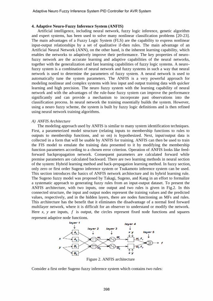
ANFIS architecture, with two inputs, one output and two rules is given in Fig.2. In this
connected structure, the input and output nodes represent the training values and the predicted
values, respectively, and in the hidden layers, there are nodes functioning as MFs and rules.
This architecture has the benefit that it eliminates the disadvantage of a normal feed forward
multilayer network, where it is difficult for an observer to understand or modify the network.
Here x, y are inputs, f is output, the circles represent fixed node functions and squares
represent adaptive node functions.
Figure 2. ANFIS architecture
Consider a first order Sugeno fuzzy inference system which contains two rules:
398
Adaptive Neuro Fuzzy Inference System PID Controller for AVR System
111111 fthen , B is Y and A is X :1 ryqxpIfRule
222222 fthen , B is Y and A is X :2 ryqxpIfRule
Where, 1p , 2p , 1q , 2q , 1r , 2r are linear parameters and 1A , 2A , 1B , 2B are nonlinear
parameter. ANFIS is an implementation of a fuzzy logic inference system with the architecture
of a five-layer feed-forward network. The system architecture consists of five layers, namely,
fuzzy layer, product layer, normalized layer, de-fuzzy layer and total output layer. With this
way ANFIS uses the advantages of learning capability of neural networks and inference
mechanism similar to human brain provided by fuzzy logic. The operation of each layer is as
follows: Here the output node i in layer l is denoted as liO .
Layer 1 is fuzzification layer. Every node i in this layer is an adaptive node with node function
4,3),(
2,1),(
,1
,1
iforxBO
iforxAO
ii
ii
(10)
Where x is the input to thi node, liO is the membership grade of x in the fuzzy set Ai.
Generalized bell membership function is popular method for specifying fuzzy sets because of
their smoothness and concise notation, and defined as
ib
i
i
iA
a
cxx
2
1
1)(
(11)
Here { ia , ib , ic } is the parameter set of the membership function. The center and width of
the membership function is varied by adjusting ic and ia . The parameter ib is used to control
the slopes at the crossover points. This layer forms the antecedents of the fuzzy rules (IF part).
Layer 2 is the rules layer. Every node in this layer is a fixed node and contains one fuzzy
rule. The output is the product of all incoming signals and represents the firing strength of each
rule.
2,1),()(2 iyxwO
iBiAii (12)
Layer 3 is normalization layer. Every node in this layer is a fixed node and the thi node
calculates the ratio of the thi rule’s firing strength to the sum of all rules’ firing strengths.
Outputs of this layer are called normalized firing strengths computed as:
2,121
3
iww
wwO i
ii (13)
Layer 4 is consequent layer. Every node in this layer is an adaptive node and computes the
values of rule consequent (THEN part) as:
)(4
iiiiiii ryqxpwfwO (14)
Layer 5 is summation layer and consists of single fixed node which calculates the overall
output as the summation of all incoming signals as:
i i
i ii
i
i
iiw
fwfwO5 (15)
It can be observed that there are two adaptive layers in this ANFIS architecture, namely the
first layer and the fourth layer. In the first layer, there are three modifiable parameters {ai, bi,
ci}, which are related to the input membership functions. These parameters are the so-called
premise parameters. In the fourth layer, there are also three modifiable parameters {pi, qi, ri},
pertaining to the first order polynomial. These parameters are the so-called consequent
parameters [22-23].
399
Kamal Yavarian, et al.

B) Learning algorithm of ANFIS
The task of the learning algorithm for this architecture is to tune all the modifiable
parameters, namely {ai, bi, ci} and {pi, qi, ri}, to make the ANFIS output match the training
data. When the premise parameters ai, bi and ci of the membership function are fixed, the
output of the ANFIS model can be written as:
221
21
21
1 fww
wf
ww
wf
(16)
Substituting Eq. (4) into Eq. (7) yields:
2211 fwfwf (17)
Substituting the fuzzy if-then rules into Eq. (8), it becomes:
)()( 22221111 ryqxpwryqxpwf (18)
After rearrangement, the output can be expressed as:
222222111111 )()()()()()( rwqywpxwrwqywpxwf
(19)
Which is a linear combination of the modifiable consequent parameters p1, q1, r1, p2, q2
and r2. The least squares method can be used to identify the optimal values of these parameters
easily. When the premise parameters are not fixed, the search space becomes larger and the
convergence of the training becomes slower. A hybrid algorithm combining the least squares
method and the gradient descent method is adopted to solve this problem. The hybrid algorithm
is composed of a forward pass and a backward pass. The least squares method (forward pass) is
used to optimize the consequent parameters with the premise parameters fixed. Once the
optimal consequent parameters are found, the backward pass starts immediately. The gradient
descent method (backward pass) is used to adjust optimally the premise parameters
corresponding to the fuzzy sets in the input domain. The output of the ANFIS is calculated by
employing the consequent parameters found in the forward pass. The output error is used to
adapt the premise parameters by means of a standard backpropagation algorithm. It has been
proven that this hybrid algorithm is highly efficient in training the ANFIS [21-23].
5. Methodology of the proposed algorithm
In this study, we propose to use an ANFIS for design the optimal PID controller of AVR
system. The network structure that implements FIS and employs hybrid-learning rules to train
is called ANFIS. The concept of the proposed technique is based on recognizing the patterns of
the sensitivities of some indices to prescribed credible events since every event could have a
signature on the patterns of these indices. In order to show the efficiency of the proposed SNR-
PSO PID controller, the obtained result is compared with the GA-PID controller with the same
evaluation function. Table.1 and Table.2 has been computed to illustrate the comparative
performance characteristics of SNR-PSO PID controller and GA PID controller respectively.
GK has been varied from 0.7 to 1.0 in steps of 0.1. g has been varied from 1.0 to 2.0 in
steps of 0.2. Thus, Table.1 includes 24 different sets of input conditions of AVR system. Each
input corresponds to nominal optimal PID gain as output. The fitness function (objective
function) for SNR-PSO is defined as:
2)(max
001.022)1000(dv
sttshOonCostFuncti
(24)
In this paper, the desired performance aspects are to minimization of cost function with the
help of any optimization technique corresponds to minimum overshoot ( shO ), minimum
settling time ( stt ) and dvmax . Therefore, it becomes an unconstrained optimization
problem to find a set of decision variables by minimizing the objective function. Maximum
400
Adaptive Neuro Fuzzy Inference System PID Controller for AVR System

population size = 50, maximum allowed iteration cycles = 100 for both SNR-PSO and GA
algorithms. The parameters of the block diagram are chosen as AK = 10, eK = sK =1.0,
a = 0.1 s, e = 0.4 s, S = 0.01 s, g = 1.0 s. Only GK and g are load dependent. The
PID control parameters for each condition are obtained by SNR-PSO and GA algorithm in
order to minimize cost function. These control parameters are used to train ANFIS with these
loading conditions in order to get on-line control parameters adaptation. These prescribed
events are defined in the event database from Table.1 (24 different sets) which the network
simulator executes the required events. The results Table 1 and table.2 show that the
performance of SNR-PSO algorithm is better than GA. From Table.1 it may be noted that
SNR-PSO based optimization technique offers a) lesser overshoot of change in terminal
voltage ( shO ), b) lesser settling time of change in terminal voltage ( stt ), and c) more
maximum derivative of change in terminal voltage ( dvmax ). Then the SNR-PSO algorithm
is used to train ANFIS. The behavioral model of the proposed technique can be represented
within the fuzzy inference system as follows:
] [S
M1,2,...,i ][ ],,[
)],([
...............................
...............................
...............................
)],([
)],([
],[
................
................
................
],[
],[
1*
2
1
1*
2
1
outin
outdip
M
Mgg
gg
gg
out
M
Mgg
gg
gg
in
DataData
DataKKK
TKOutput
TKOutput
TKOutput
Data
TK
TK
TK
Data
That:
gK : Under the thi event;
gT : Under the thi event;
:M The Number of performed test
Table 1. Optimized PID gains and transient response parameters based SNR-PSO method
MF dvmax stt shO dK iK pK Type of
controller g
GK
0.3675 0.1103 0.5341 9.7953e-8 0.2474 0.5274 0.7762 SNR-PSO 1 0.7
0.4292 0.1131 0.5922 1.9037e-6 0.2750 0.5102 0.8430 SNR-PSO 1.2 0.5544 0.1045 0.6802 8.7316e-8 0.2893 0.4680 0.8629 SNR-PSO 1.4
0.3511 0.1205 0.5312 1.8994e-8 0.4003 0.5284 1.0964 SNR-PSO 1.6
0.3856 0.1187 0.5609 2.5885e-7 0.4439 0.5291 1.1862 SNR-PSO 1.8
0.3790 0.1171 0.5532 4.5202e-7 0.4852 0.5184 1.2800 SNR-PSO 2
0.3628 0.1130 0.5333 3.7172e-7 0.2167 0.4616 0.6795 SNR-PSO 1 0.8
0.5486 0.0960 0.6633 2.3390e-7 0.2698 0.4146 0.6736 SNR-PSO 1.2 0.3562 0.1197 0.5353 1.3507e-7 0.3052 0.4619 0.8655 SNR-PSO 1.4
0.3549 0.1200 0.5343 6.9746e-7 0.3496 0.4608 0.9560 SNR-PSO 1.6
0.3909 0.1146 0.5616 2.8920e-7 0.3666 0.4490 1.0127 SNR-PSO 1.8 0.7187 0.0934 0.7772 1.5401e-8 0.3089 0.3815 0.9181 SNR-PSO 2
0.4392 0.1096 0.5966 9.1740e-9 0.1776 0.3913 0.5701 SNR-PSO 1 0.9 0.4795 0.1037 0.6217 1.5431e-9 0.2048 0.3887 0.6382 SNR-PSO 1.2
0.3543 0.1191 0.5326 6.6844e-7 0.2716 0.4108 0.7699 SNR-PSO 1.4
0.3967 0.1169 0.5688 5.1328e-8 0.3017 0.3986 0.8269 SNR-PSO 1.6 0.4032 0.1144 0.5716 2.2475e-10 0.3265 0.3963 0.8953 SNR-PSO 1.8
0.8295 0.0920 0.8434 1.8179e-7 0.2579 0.3202 0.7700 SNR-PSO 2
0.4931 0.1053 0.6330 4.7599e-6 0.1407 0.3278 0.4938 SNR-PSO 1 1 0.3760 0.1123 0.5435 8.4153e-8 0.2066 0.3681 0.6147 SNR-PSO 1.2
0.4633 0.1014 0.6050 6.2972e-8 0.2094 0.3239 0.6466 SNR-PSO 1.4
0.4054 0.1125 0.5713 8.7420e-8 0.2579 0.3577 0.7342 SNR-PSO 1.6 0.3549 0.1188 0.5330 1.6682e-7 0.3112 0.3668 0.8367 SNR-PSO 1.8
0.3989 0.1152 0.5689 2.2754e-7 0.3308 0.3586 0.8829 SNR-PSO 2
401
Kamal Yavarian, et al.

Table 2. Optimized PID gains and transient response parameters based GA method
MF dvmax stt shO dK iK pK Type of
controller g
GK
4.1811 0.0275 1.6882 1.1203e-5 0.2367 0.4220 0.6551 GA 1 0.7
6.5948 0.0428 2.4429 2.8360e-5 0.5247 0.4542 0.9151 GA 1.2 6.3102 0.0364 2.3132 4.4987e-5 0.4939 0.4273 0.9125 GA 1.4
4.1095 0.0374 1.5823 9.4437e-5 0.5593 0.5480 1.2126 GA 1.6
6.1831 0.0383 2.3405 1.4978e-5 0.6776 0.4422 1.1255 GA 1.8 4.4008 0.0337 1.8713 1.2733e-5 0.6219 0.4658 1.2289 GA 2
4.7617 0.0381 1.9960 3.0075e-5 0.3223 0.4233 0.7207 GA 1 0.8
8.1600 0.0416 2.7138 4.6572e-5 0.4495 0.3566 0.7268 GA 1.2 6.8960 0.0437 2.5225 9.8200e-6 0.5516 0.3956 0.8802 GA 1.4
5.6657 0.0370 2.2132 1.9282e-5 0.5015 0.3920 0.9117 GA 1.6
4.2649 0.0324 1.1813 1.5959e-5 0.4655 0.4034 0.9752 GA 1.8 4.9911 0.0390 2.0706 2.1478e-5 0.6649 0.4259 1.1555 GA 2
5.3333 0.0332 2.0781 3.2499e-5 0.2410 0.3329 0.5579 GA 1 0.9
4.8557 0.0258 1.7493 5.4010e-5 0.2042 0.3083 0.5363 GA 1.2
7.9271 0.0329 2.6255 3.2816-5 0.3445 0.2833 0.6078 GA 1.4
4.2734 0.0341 1.8447 1.1333e-5 0.3931 0.3680 0.8248 GA 1.6
5.7596 0.0410 2.2321 4.2583e-5 0.5709 0.3721 0.9491 GA 1.8 4.4570 0.0271 1.7352 2.8931e-5 0.3625 0.3214 0.8213 GA 2
5.9209 0.0260 1.8215 1.0586e-4 0.1549 0.2734 0.4271 GA 1 1
3.6611 0.0360 1.4771 8.4172e-5 0.2774 0.3837 0.6843 GA 1.2 4.1462 0.0332 1.7960 1.0506e-5 0.2975 0.3293 0.6662 GA 1.4
5.3835 0.0372 2.1546 1.3137-5 0.4019 0.3203 0.7423 GA 1.6
7.6608 0.0411 2.6529 1.7451e-5 0.5272 0.2956 0.7662 GA 1.8 4.5843 0.0286 1.6255 8.4878e-5 0.3470 0.3103 0.7936 GA 2
6. Architecture of the Proposed Algorithm
The architecture of the proposed Intelligent-based for determine the optimal PID controller
of AVR system is shown in figure 3. It is consists of three main modules; namely the input
module, fuzzy inference system, and the output module. These modules are described as
follows:
A) Input Module
The input to this module are GK & g .
B) Fuzzy Inference system (FIS)
This module is the fuzzy inference system software model of design the optimal PID controller
of AVR system. This module has already been discussed in Section II.
C) Output Module
This is an output unit which include pK , iK and dK .
Figure 3. Architecture of the proposed ANFIS-based controller of AVR system
In this paper a fuzzy inference system models which takes GK and g as inputs and pK ,
iK and dK as output. The result obtained to indicate that ANFIS is effective method for design
an intelligent PID controller.
7. Simulation Results
In this section, the efficiency and effectiveness of the introduced SNR-PSO algorithm is
validated. The block diagram of the AVR system with PID controller is shown in Fig.1. The
Fuzzy Inference System
Input Module
Output Module
402
Adaptive Neuro Fuzzy Inference System PID Controller for AVR System

three controller parameters pK , iK and dK all range from 0.2 to 2. Step perturbation of 1p.u. of
reference voltage has been applied to get the transient response of incremental change in
terminal voltage in the present work. In order to emphasize the advantages of the proposed
SNR-PSO PID controller, we also compared with the GA- PID controller. In this compared the
characteristics of the two controllers had the same evaluation function and individual
definition.
A) Case 1: GK =0.7 , g =1.6
In this case study for step response without controller, percent of overshoot (M P %) is
21.54% and settling time (Ts) is very major because we have steady state error. The terminal
voltage step responses of the AVR without controller, SNR-PSO controller and GA controller
are shown in Fig.4. As can be seen, the SNR-PSO controller could create very perfect step
response of the AVR system, and thus the SNR-PSO controller is better than the GA controller.
Figure 4. The step response of AVR system without controller, SNR-PSO and GA controller
B) Case 2: GK =0.8 , g =1.2
In this case study for step response without controller, percent of overshoot (M P %) is very
high and settling time (Ts) is very major because we have steady state error. The terminal
voltage step responses of the AVR without controller, SNR-PSO controller and GA controller
are shown in Fig.5. As can be seen, the SNR-PSO controller could create very perfect step
response of the AVR system, and thus the SNR-PSO controller is better than the GA controller.
Figure 5. The step response of AVR system without controller and SNR-PSO and GA
controllers
C) Case 3: GK =0.9 , g =1.4
In this case study for step response without controller, percent of overshoot (M P %) is very
high and settling time (Ts) is very major because we have steady state error. The terminal
voltage step responses of the AVR without controller, SNR-PSO controller and GA controller
are shown in Fig.6. As can be seen, the SNR-PSO controller could create very perfect step
response of the AVR system, and thus the SNR-PSO controller is better than the GA controller.
0 0.5 1 1.5 2 2.5 3 3.5 4 4.5 50
0.2
0.4
0.6
0.8
1
1.2
Time (sec)
Am
plitu
de
without Controller
SNR-PSO Controller
GA Controller
0 0.5 1 1.5 2 2.5 3 3.5 4 4.5 50
0.2
0.4
0.6
0.8
1
1.2
Time (sec)
Am
plitu
de
without Controller
SNR-PSO Controller
GA Controller
403
Kamal Yavarian, et al.

Figure 6. The step response of AVR system without controller, SNR-PSO and genetic
controllers
D) Case 4: GK =1 , g =1.8
In this case study for step response without controller, percent of overshoot (M P %) is very
high and settling time (Ts) is very major because we have steady state error. The terminal
voltage step responses of the AVR without controller, SNR-PSO controller and GA controller
are shown in Fig.7. As can be seen, the SNR-PSO controller could create very perfect step
response of the AVR system, and thus the SNR-PSO controller is better than the GA controller.
Figure 7. The step response of AVR system without controller, SNR-PSO and genetic
controllers
In this part, the performance of the proposed self-tuning SNR-PSO and GA ANFIS
controller is compared with the robust SNR-PSO controller for different system condition. In
the self tuning ANFIS controller, the PID parameter controller is tuned on-line with respect the
system condition but in the robust controller PID parameters is fixed for all system conditions.
In table.3 the robust PID coefficient is determined for AVR system based on SNR-PSO for all
24 case considered in Table.1.
Table 3. Robust PID gains based SNR-PSO method
Type of controller pK iK dK
Robust Controller 1.2352 0.2132 0.3341
Table 4. ANFIS PID gains based SNR-PSO & GA
Type of
controller method gg ,K pK
iK dK shO
st
ANFIS
Controller
SNR-PSO 0.77, 1.33
0.8437 0.4672 0.2891 7.5674e-005 0.5761
GA 0.8471 0.4115 0.4332 8.7515e-005 2.1674
ANFIS
Controller SNR-PSO
0.83,1.45 0.8278 0.4330 0.2874 1.5000e-005 0.5771
GA 0.8273 0.3861 0.4247 1.4836e-004 2.0719
ANFIS
Controller SNR-PSO
0.92,1.67 0.8190 0.3813 0.2919 1.7288e-004 0.5777
GA 0.8143 0.3490 0.4230 2.3501e-004 2.0234
ANFIS
Controller SNR-PSO
0.97,1.88 0.8474 0.3514 0.3096 6.3303e-004 0.5973
GA 0.8437 0.3304 0.4463 1.5766e-005 2.0294
0 0.5 1 1.5 2 2.5 3 3.5 4 4.5 50
0.2
0.4
0.6
0.8
1
1.2
Time (sec)
Am
plit
ud
e
without Controller
SNR-PSO Controller
GA Controller
0 0.5 1 1.5 2 2.5 3 3.5 4 4.5 50
0.2
0.4
0.6
0.8
1
1.2
Time (sec)
Am
plit
ud
e
without Controller
SNR-PSO Controller
GA Controller
404
Adaptive Neuro Fuzzy Inference System PID Controller for AVR System
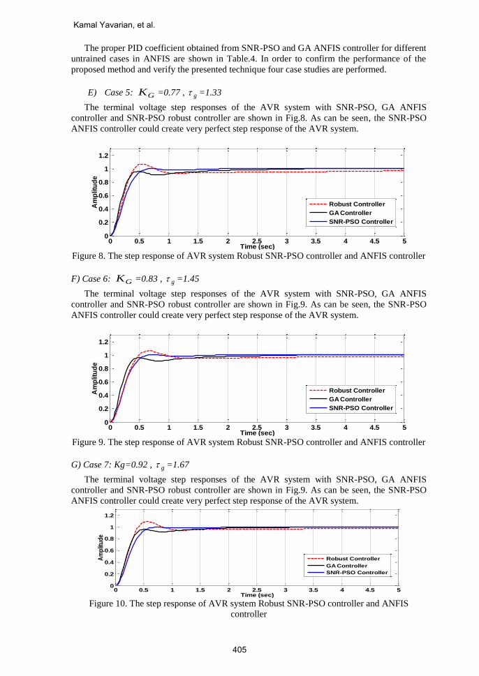
The proper PID coefficient obtained from SNR-PSO and GA ANFIS controller for different
untrained cases in ANFIS are shown in Table.4. In order to confirm the performance of the
proposed method and verify the presented technique four case studies are performed.
E) Case 5: GK =0.77 , g =1.33
The terminal voltage step responses of the AVR system with SNR-PSO, GA ANFIS
controller and SNR-PSO robust controller are shown in Fig.8. As can be seen, the SNR-PSO
ANFIS controller could create very perfect step response of the AVR system.
Figure 8. The step response of AVR system Robust SNR-PSO controller and ANFIS controller
F) Case 6: GK =0.83 , g =1.45
The terminal voltage step responses of the AVR system with SNR-PSO, GA ANFIS
controller and SNR-PSO robust controller are shown in Fig.9. As can be seen, the SNR-PSO
ANFIS controller could create very perfect step response of the AVR system.
Figure 9. The step response of AVR system Robust SNR-PSO controller and ANFIS controller
G) Case 7: Kg=0.92 , g =1.67
The terminal voltage step responses of the AVR system with SNR-PSO, GA ANFIS
controller and SNR-PSO robust controller are shown in Fig.9. As can be seen, the SNR-PSO
ANFIS controller could create very perfect step response of the AVR system.
Figure 10. The step response of AVR system Robust SNR-PSO controller and ANFIS
controller
0 0.5 1 1.5 2 2.5 3 3.5 4 4.5 50
0.2
0.4
0.6
0.8
1
1.2
Time (sec)
Am
plit
ud
e
Robust Controller
GA Controller
SNR-PSO Controller
0 0.5 1 1.5 2 2.5 3 3.5 4 4.5 50
0.2
0.4
0.6
0.8
1
1.2
Time (sec)
Am
plit
ud
e
Robust Controller
GA Controller
SNR-PSO Controller
0 0.5 1 1.5 2 2.5 3 3.5 4 4.5 50
0.2
0.4
0.6
0.8
1
1.2
Time (sec)
Am
plit
ud
e
Robust Controller
GA Controller
SNR-PSO Controller
405
Kamal Yavarian, et al.

H) Case 8: GK =0.97, g =1.88
The terminal voltage step responses of the AVR system with SNR-PSO, GA ANFIS
controller and SNR-PSO robust controller are shown in Fig.11. As can be seen, the SNR-PSO
ANFIS controller could create very perfect step response of the AVR system.
Figure 11. The step response of AVR system Robust SNR-PSO controller and ANFIS
controller
8. Conclusion
This paper presents a design methodology based on ANFIS for an adaptive PID automatic
voltage regulator system. A wide-range of load change is considered at which SNR-PSO and
GA algorithm are employed to obtain the parameters of the PID controller yielding optimal
responses. The data obtained through SNR-PSO and GA algorithm are used to train both
ANFIS agent, which give the optimal controller parameters at any load point within the
specified range. By using this algorithm the speed of convergence and accuracy can be
increased and the system can be used for many real time applications. Superior performance,
robustness, and efficiency of the proposed method have been proved through extensive
simulation results. The proposed SNR-PSO based ANFIS controller is the most powerful
approach to retrieve the adaptiveness in the case of nonlinear system. The results show that this
approach is robustness and suitable for optimizing various control problems including adaptive
control system with large scale dimensions.
9. References
[1]. O’DWYER A.: ‘Handbook of PI and PID controller tuning rules’ (Imperial College
Press, London, 2003).
[2]. Indranil Pan, Saptarshi Das ''Chaotic multi-objective optimization based design of
fractional order PIλD
μ controller in AVR system'', International Journal of Electrical
Power & Energy Systems, Volume 43, Issue 1, December 2012, Pages 393–407
[3]. Hui Zhu, Lixiang Li, Ying Zhao, Yu Guo, Yixian Yang ''CAS algorithm-based optimum
design of PID controller in AVR system'' Chaos, Solitons & Fractals Volume 42, Issue 2,
30 October 2009, Pages 792–800
[4]. Dong Hwa Kim, ''Hybrid GA–BF based intelligent PID controller tuning for AVR
system'' Applied Soft Computing Volume 11, Issue 1, January 2011, Pages 11–22
[5]. Fabrizio Padula, Antonio Visioli, ''Tuning rules for optimal PID and fractional-order PID
controllers'' Journal of Process Control Volume 21, Issue 1, January 2011, Pages 69–81
[6]. Leandro dos Santos Coelho, ''Tuning of PID controller for an automatic regulator voltage
system using chaotic optimization approach'' Chaos, Solitons & Fractals Volume 39,
Issue 4, 28 February 2009, Pages 1504–1514
[7]. S. Panda, B.K. Sahu, P.K. Mohanty ''Design and performance analysis of PID controller
for an automatic voltage regulator system using simplified particle swarm optimization''
Journal of the Franklin Institute, Volume 349, Issue 8, October 2012, Pages 2609–2625
[8]. Saptarshi Das, Indranil Pan, Shantanu Das, Amitava Gupta ,''A novel fractional order
fuzzy PID controller and its optimal time domain tuning based on integral performance
0 0.5 1 1.5 2 2.5 3 3.5 4 4.5 50
0.2
0.4
0.6
0.8
1
1.2
Time (sec)
Am
plit
ud
e
Robust Controller
GA Controller
SNR-PSO Controller
406
Adaptive Neuro Fuzzy Inference System PID Controller for AVR System

indices'' Engineering Applications of Artificial Intelligence Volume 25, Issue 2, March
2012, Pages 430–442
[9]. H. Zhu, L. Li, and Y. Zhao, “CAS algorithm-based optimum design of PID controller in
AVR system,” Chaos, Solitons and Fractals, vol. 42, pp. 792–800, 2009.
[10]. Devaraj, D. Selvabala, B. ''Real-coded genetic algorithm and fuzzy logic approach for
real-time tuning of proportional-integral - derivative controller in automatic voltage
regulator system'' Generation, Transmission & Distribution, IET, Volume: 3, Issue: 7
Page(s): 641 – 649
[11]. Hasanien, H. M., ''Design Optimization of PID Controller in Automatic Voltage
Regulator System Using Taguchi Combined Genetic Algorithm Method'' Systems
Journal, IEEE, Volume: PP , Issue: 99 Page(s): 1, 2012
[12]. Z. L. Gaing, “A Particle Swarm Optimization Approach for Optimum Design of PID
Controller in AVR System,” IEEE Transactions on Energy Conversion, Vol. 19, No. 2,
June 2004.
[13]. V.Mukherjee, and S.P. Ghoshal, “Comparison of intelligent fuzzy based AGC
coordinated PID controlled and PSS controlled AVR system,” Electrical Power and
Energy Systems, vol. 29, pp. 679–689, 2007.
[14]. V.Mukherjee, and S.P. Ghoshal, “Intelligent particle swarm optimized fuzzy PID
controller for AVR system,” Electric Power Systems Research, vol. 77, pp. 1689–1698,
2007.
[15]. J. Faiz, Gh. Shahgholian, M. Arezoomand“ Analysis and Simulation of the AVR System
and Parameters Variation Effects,” POWERENG 2007 in Setubal, Portugal, pp.450-453,
April 12-14, 2007.
[16]. M. S. Widyan, "On the effect of AVR gain on bifurcations of subsynchronous resonance
in power systems” Electrical Power and Energy Systems, vol. 32, pp. 656–663, 2010.
[17]. Yi. Tang, M. Cui, C. Hua, L. Li, and Y. Yang, “Optimum design of fractional order PID
controller for AVR system using chaotic ant swarm,” Expert Systems with Applications,
vol. 39, pp. 6887–6896, 2012.
[18]. S.P. Ghoshal, “Optimizations of PID Gains by Particle Swarm Optimizations in Fuzzy
based Automatic Generation Control”, Electric Power Systems Research, Vol. 70, No. 3,
pp.203-212, 2004.
[19]. Ifeanyi E. Madu, Christian N. Madu, "Design optimization using signal-to-noise ratio"
Simulation Practice and Theory 7 (1999) 349-372
[20]. Gupta MM, Rao DH. Neuro-control systems: theory and applications. Piscataway, NJ:
IEEE press; 1994.
[21]. Yen J, Langari R, Zadeh LA. Industrial applications of fuzzy logic and intelligent
systems. New York, NY: IEEE Press; 1995.
[22]. Jang J-SR. ANFIS adaptive-network-based fuzzy inference system. IEEE Trans Syst Man
Cyber 1993;23(3):665–85.
[23]. Gupta MM, Rao DH. Newo-control systems: theory and applications. Piscataway, NJ:
IEEE Press; 1994.
Kamal Yavarian was born in Ardabil, Iran, in 1978. He received the B.Sc.
degree in Electrical Power Engineering from Islamic Azad University,
Ardabil branch, Iran in 2000 and M.Sc. degree in Electrical Power
Engineering from Islamic Azad University, South Tehran Branch, Tehran,
Iran in 2006.Since 2007 he has been with the faculty of Technical and
Engineering, Islamic Azad University, Ardabil branch, where he is currently
an instructor. He is Ph. D. student in Electrical Power Engineering, Islamic
Azad University, Science and Research Branch, Tehran, Iran. His current
research interests include Power System Stability and Control, Power System Reliability,
Electric Distribution Planning and Operation, Distributed Generation, and Energy
Management.
407
Kamal Yavarian, et al.

Amir Mohammadian was born in Ardebil, Iran in 1987. He received B.Sc.
degree in Electrical Engineering from Ardebil Branch of Islamic Azad
University (IAU), Ardebil, Iran in 2009. He received his M.Sc. degree in
Electrical Engineering from Electrical Engineering Department of the
Mohaghegh Ardabili University, Ardabil, Iran in 2013. Currently, he is a
Lecturer of University of Applied Science and Technology, Ardabil, Iran. His
current research interests in the Application of Robust Control, Artificial
Intelligence and Heuristic Optimization Methods to Power System Control
Design.
Farid Hashemi was born in Ardebil, Iran, in 1987. He received the B.Sc.
degree in electrical engineering from Ardebil Branch of Islamic Azad
University (IAU), Ardebil, Iran, and the M.Sc. degree in electrical
engineering from Science and Research Branch of Islamic Azad University
(IAU), Tehran, Iran, in 2009 and 2011, respectively. He is currently working
toward the Ph.D. degree in the Department of Electrical Engineering, Shiraz
University, Shiraz, Iran. His current research interests include Heuristic
Algorithms, ANN, Fuzzy Logic, Power System Control, Protection and
Control of the Distributed Generation and Microgrid.
408
Adaptive Neuro Fuzzy Inference System PID Controller for AVR System