Embed Size (px)
Citation preview

Aalborg Universitet
Adaptive sliding mode control of interleaved parallel boost converter for fuel cellenergy generation systemEl Fadil, H.; Giri, F. ; Guerrero, Josep M.
Published in:Mathematics and Computers in Simulation
DOI (link to publication from Publisher):10.1016/j.matcom.2012.07.011
Publication date:2013
Document VersionEarly version, also known as pre-print
Link to publication from Aalborg University
Citation for published version (APA):El Fadil, H., Giri, F., & Guerrero, J. M. (2013). Adaptive sliding mode control of interleaved parallel boostconverter for fuel cell energy generation system. DOI: 10.1016/j.matcom.2012.07.011
General rightsCopyright and moral rights for the publications made accessible in the public portal are retained by the authors and/or other copyright ownersand it is a condition of accessing publications that users recognise and abide by the legal requirements associated with these rights.
? Users may download and print one copy of any publication from the public portal for the purpose of private study or research. ? You may not further distribute the material or use it for any profit-making activity or commercial gain ? You may freely distribute the URL identifying the publication in the public portal ?
Take down policyIf you believe that this document breaches copyright please contact us at [email protected] providing details, and we will remove access tothe work immediately and investigate your claim.
Downloaded from vbn.aau.dk on: juli 15, 2018

Accepted Manuscript
Title: Adaptive sliding mode control of interleaved parallelboost converter for fuel cell energy generation system
Authors: H. El Fadil, F. Giri, J.M. Guerrero
PII: S0378-4754(12)00174-7DOI: doi:10.1016/j.matcom.2012.07.011Reference: MATCOM 3831
To appear in: Mathematics and Computers in Simulation
Received date: 25-10-2011Revised date: 8-5-2012Accepted date: 1-7-2012
Please cite this article as: H.E. Fadil, F. Giri, J.M. Guerrero, Adaptive sliding modecontrol of interleaved parallel boost converter for fuel cell energy generation system,Mathematics and Computers in Simulation (2010), doi:10.1016/j.matcom.2012.07.011
This is a PDF file of an unedited manuscript that has been accepted for publication.As a service to our customers we are providing this early version of the manuscript.The manuscript will undergo copyediting, typesetting, and review of the resulting proofbefore it is published in its final form. Please note that during the production processerrors may be discovered which could affect the content, and all legal disclaimers thatapply to the journal pertain.

Page 1 of 26
Accep
ted
Man
uscr
ipt
1
Adaptive sliding mode control of interleaved parallel boost converter for
fuel cell energy generation system
H. El Fadil1*, F. Giri1, J.M. Guerrero2
1. GREYC Lab, Université de Caen Basse-Normandie, UMR 6072, 14032 Caen, France. (E-mails: [email protected] , [email protected] ; * Corresponding Author)
2. Institute of Energy Technology, Aalborg University, Aalborg East DK-9220, Denmark (e-mail: [email protected]).
Abstract - This paper deals with the problem of controlling energy generation systems
including fuel cells (FCs) and interleaved boost power converters. The proposed nonlinear
adaptive controller is designed using sliding mode control (SMC) technique based on the
system nonlinear model. The latter accounts for the boost converter large-signal dynamics as
well as for the fuel-cell nonlinear characteristics. The adaptive nonlinear controller involves
online estimation of the DC bus impedance ‘seen’ by the converter. The control objective is
threefold: (i) asymptotic stability of the closed loop system, (ii) output voltage regulation
under bus impedance uncertainties and (iii) equal current sharing between modules. It is
formally shown, using theoretical analysis and simulations, that the developed adaptive
controller actually meets its control objectives.
Keywords – Fuel cell, interleaved boost converter, sliding mode control, adaptive control.
1. Introduction
It is well established that the past-decades intensive use of fossil fuel has already caused
global environmental problems. Furthermore, the gap between fossil fuel resources and the
global energy demand has been growing over the few past years leading to significant oil
price increase. More recently, the Fukushima disaster has showed the drawbacks of using
nuclear energy as alternative to fossil fuel. On the other hand, renewable energy has gained in
popularity, since their efficiency is continuously improved and their cost is continuously
reduced. Indeed, renewable energy systems produce electric power without polluting the
environment, transforming free inexhaustible energy resources, like solar radiation or wind,
Manuscript
Page 2 of 26
Accep
ted
Man
uscr
ipt
2
into electricity. The world’s demand for electrical energy has been continuously increasing
and is expected to continue growing, while the majority of the electrical energy in most
countries is generated by conventional energy sources. The ongoing global climate change,
the diminution of fossil fuel resources and the collective fear of energy supply shortage have
made the global energy trends more complex. However, it is disadvantageous to meet the
rising electricity demand by establishing more conventional power systems. As the electricity
is delivered from the main power plants to the end-users (customers) at a high voltage level
along with long length transmission lines, the end-users get short of electricity whenever the
lines are destroyed by unexpected events (e.g. natural disasters) or when fuel suppliers fail.
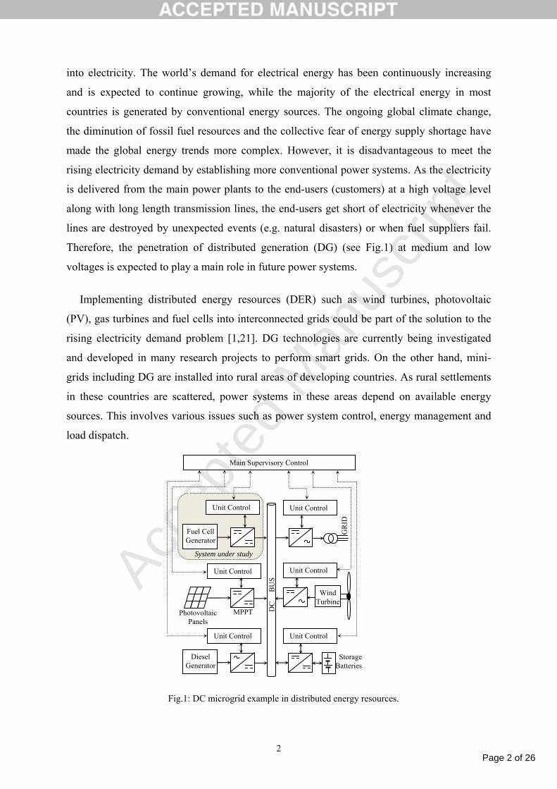
Therefore, the penetration of distributed generation (DG) (see Fig.1) at medium and low
voltages is expected to play a main role in future power systems.
Implementing distributed energy resources (DER) such as wind turbines, photovoltaic
(PV), gas turbines and fuel cells into interconnected grids could be part of the solution to the
rising electricity demand problem [1,21]. DG technologies are currently being investigated
and developed in many research projects to perform smart grids. On the other hand, mini-
grids including DG are installed into rural areas of developing countries. As rural settlements
in these countries are scattered, power systems in these areas depend on available energy
sources. This involves various issues such as power system control, energy management and
load dispatch.
Fig.1: DC microgrid example in distributed energy resources.
Wind Turbine
Photovoltaic Panels
MPPT
Fuel Cell Generator
GR
ID
Diesel
Generator
Unit Control
Unit Control
Unit Control
Unit Control
Unit Control
Main Supervisory Control
Unit Control
System under study
Storage Batteries
DC
B
US
Page 3 of 26
Accep
ted
Man
uscr
ipt
3
Among renewable energies, hydrogen and fuel cell are considered as promising
alternatives from both energy storage and supply reliability viewpoints. Indeed, these sources
do not only feature a high-efficiency chemical-energy conversion (into electrical energy) but
also feature low emissions [24,25,26].
The proliferation of DC-ended sources like PV, batteries, supercapacitors and FCs has
made it possible to conceive DC distribution systems or DC microgrids which are main tools
for energy sources integration. As the various types of sources have different characteristics,
it is important to make sure that each source comes into operation only when ambient
conditions (wind, radiation…) are favourable. In this respect, it is well known that FCs does
not well bear sudden current variations (current derivative is limited). This is coped with by
including bidirectional energy modules (e.g. batteries, supercapacitors) in DERs. Doing so,
sudden current variations are supported by the rapid sources. The repartition of the global
current generation effort on the different sources of a DER is managed by the main
supervisory control (MSC) (Fig. 1). Specifically, when a sudden current demand is detected in
the DC bus, the MSC acts on one (or more) rapid source converter changing its direction to
discharging mode so that is provides the extra current.
It turns out that, in DERs, different power converters (between sources and DC bus) are
involved. In this paper, the focus is made on the integration of fuel cell, through interleaved
boost converter (IBC), into a DC microgrid (Fig.1). The IBC topology consists of a number of
paralleled boost converters controlled by means of interleaving control techniques in contrast
to the conventional high power boost converter [33]. The aim is to control the FC-IBC
association so that the integration to the microgrid is accomplished complying with
interconnection conventions. In particular, the DC link voltage must be tightly regulated.
IBCs offer many benefits making them particularly suitable in different renewable energy
applications, e.g. battery chargers and maximum power point tracking (MPPT) in PV
conversion. Indeed, they offer good efficiency and voltage/current ripples reduction [20,31].
In this respect, recall that FCs are vulnerable to current ripples making inappropriate the
association with more basic converters, particularly boost converters which are known to
inject current ripples [32]. Using interleaving techniques, the ripples of corresponding
inductor currents and capacitor voltage are diminished, making possible size reduction of
inductors and capacitor [27,6]. Moreover, the power losses in IBCs are reduced (compared to
basic boost converters) because the switching frequency can be made smaller by increasing
the number of branches. Energetic efficiency can also be improved by considering variants of
the IBC topology, e.g. soft switching and resonant techniques, or coupled inductors [27].
Page 4 of 26
Accep
ted
Man
uscr
ipt
4
On the other hand, the research in the fuel cell field has gained more importance and industry
applications range from low power (50W) to high power (more than 250kW) [15]. In order to
obtain efficient fuel cell systems, the DC/DC converter should be properly designed
[3,12,14]).
The above mentioned benefits makes IBCs good candidate for interfacing fuel cell and DC
buses [10,19]. The control of IBC topology has been dealt with using conventional linear
control techniques [2,11,23,26,29]. The point is that, both the IBC converter and the fuel cell
exhibit highly nonlinear behavior making linear controllers only effective within around
specific operation points. In this paper, the problem of controlling fuel cell IBC systems is
dealt with based on a more accurate model that really accounts for the system nonlinearities.
Doing so, the model turns out to be well representative of both the boost converter large-
signal dynamic behavior and the fuel-cell nonlinear characteristics. A nonlinear adaptive
controller is designed, using the sliding mode control (SMC) technique, to achieve three
objectives: (i) asymptotic stability of the closed loop system; (ii) tight output DC link voltage
regulation, despite bus impedance uncertainties; (iii) and equal current sharing between
modules. Accordingly, the controller involves online estimation of the DC bus impedance
‘seen’ by the converter. It is formally shown, using theoretical analysis and simulations, that
the developed adaptive controller actually meets its control objectives.
The paper is organized as follows. In Section 2, the IBC for fuel cell applications are
described and modeled. Section 3 is devoted to the controller design and closed-loop
theoretical analysis. The controller tracking performances are illustrated through numerical
simulations in Section 4. Section 5 provides the conclusion of the paper.
2. General norms and system modeling
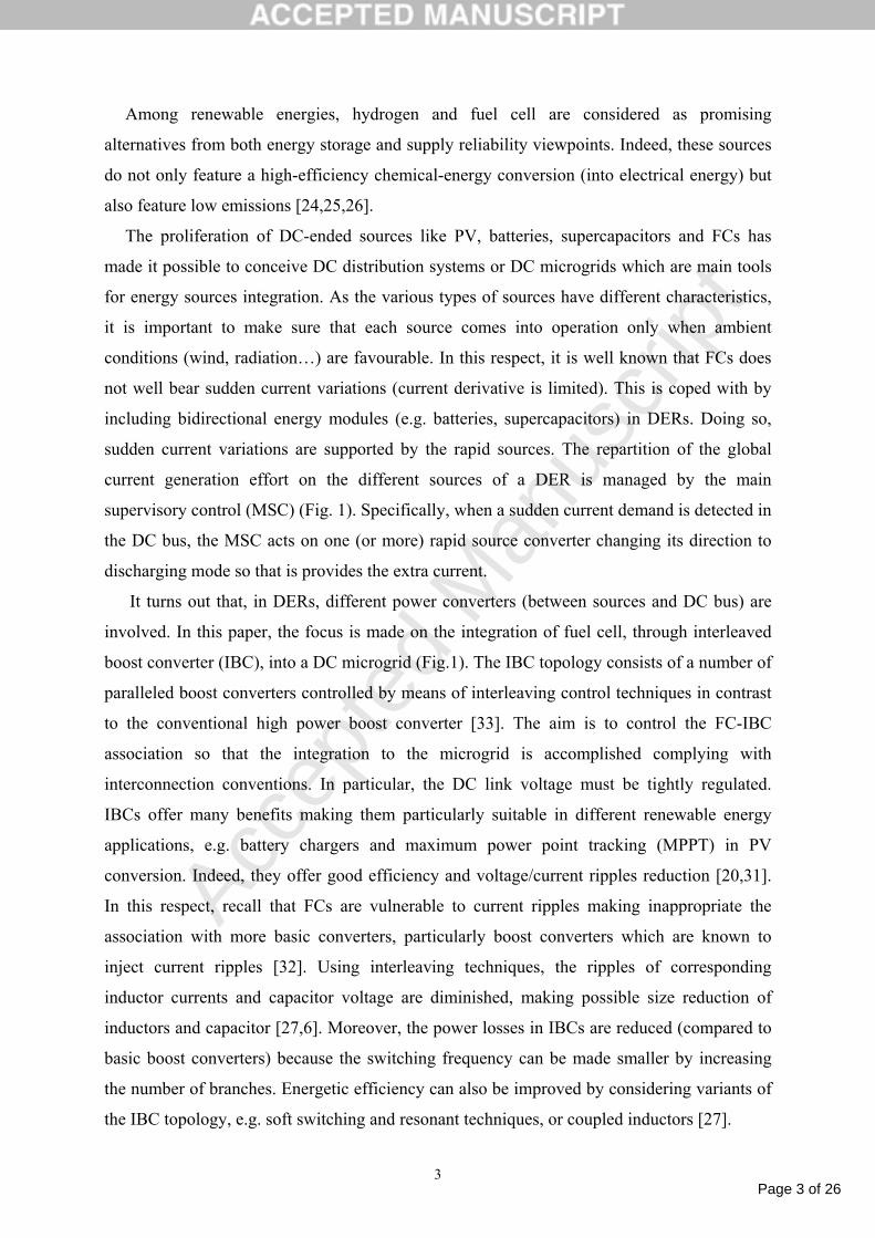
Figure 2 shows the power stage of a fuel cell interleaved boost converter (FC-IBC) system.
It consists of a FC generator and N-interleaved boost converters connected in parallel sharing
a common DC bus. Each boost converter consisted of an input inductor Lk, a static switch (Sk)
controlled by the binary input signal uk, and an output diode Dk (k =1,…, N). Each diode
cathode is connected to the same point with the output capacitor C in parallel with the load
represented by a pure resistance R, according to the input impedance of the DC bus. This
impedance is actually unknown because it depends on the power demand. This uncertainty
will be investigated in next section.
Page 5 of 26
Accep
ted
Man
uscr
ipt
5
Fig.2: Power stage of the FC-IBC system
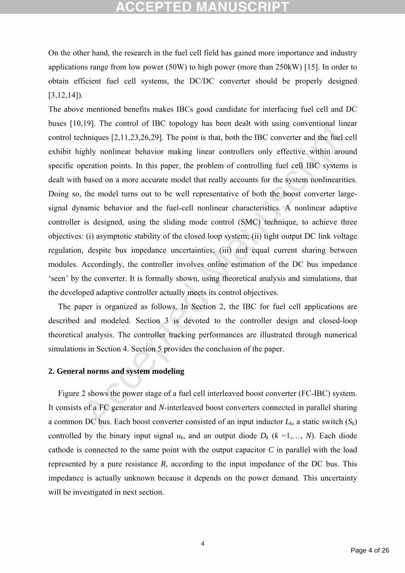
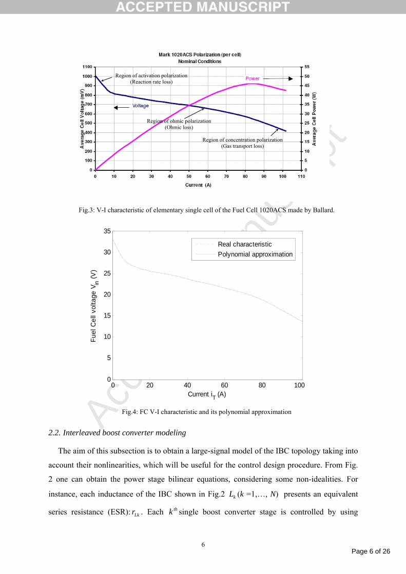
2.1. Fuel cell V-I static characteristic
The static V-I polarization curve for a single-cell fuel cell is shown in Fig. 3, where the
drop of the fuel cell voltage with load current density can be observed. This voltage reduction
is caused by three major losses [13]: activation losses, ohmic losses, and transport losses. The
V-I polarization curve of Fig.3 corresponds to a Ballard manufacturer elementary FC
1020ACS. The fuel cell used in this application is a proton exchange membrane (PEM), being
the operation temperature relatively low. As can be seen from Fig. 3 there is a big difference
between the minimum and maximum voltage of the FC generator. Then, it is very important
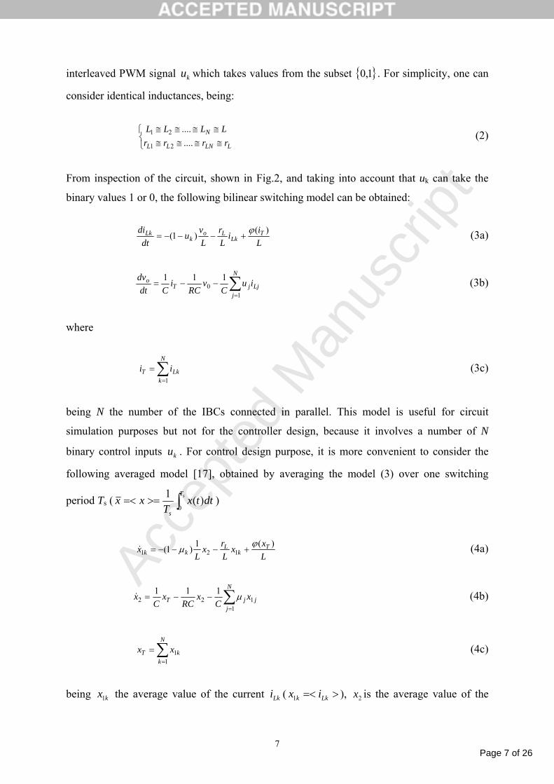
to take into account the nonlinearity of this characteristic for control design purposes. With
this aim, a polynomial approximation of the V-I curve of Fig.3 is obtained by using the polyfit
function of MATLAB defined as follows:
)()(7
0T
def
n
nTnin iipv ϕ==∑
=
(1)
where )7,...,0( =npn are the coefficients listed in Table 1.
Table 1: polynomial coefficients
30 10=p 9.351 −=p 45.22 =p
09.03 −=p 34 10x8.1 −=p 5
5 10x2−=p 7
6 10x14.1 −=p 107 10x64.2 −−=p
Figure 4 shows that the polynomial approximation fits perfectly the real V-I curve. Thus, the
approximated function (1) will be used for the control design, which will be addressed in
section 3.
L1 D1iL1
S1
u1
S2
u2
SN
uNRC
+ vo
-vin
Fuel Cell
L2
LN
D2
DNiT
iL2
iLN
io
Page 6 of 26
Accep
ted
Man
uscr
ipt
6
Fig.3: V-I characteristic of elementary single cell of the Fuel Cell 1020ACS made by Ballard.
0 20 40 60 80 1000
5
10
15
20
25
30
35
Current iT (A)
Fuel
Cel
l vol
tage
Vin
(V)
Real characteristicPolynomial approximation
Fig.4: FC V-I characteristic and its polynomial approximation
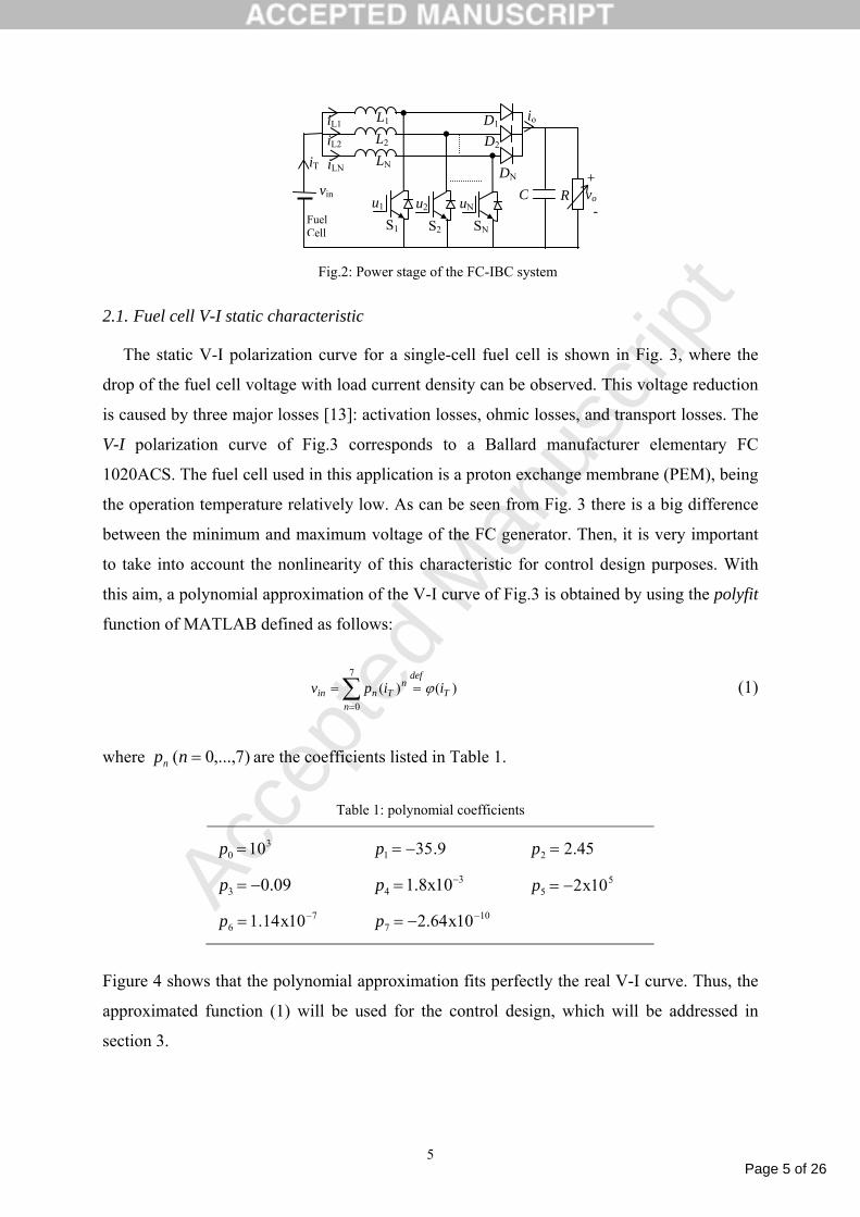
2.2. Interleaved boost converter modeling
The aim of this subsection is to obtain a large-signal model of the IBC topology taking into
account their nonlinearities, which will be useful for the control design procedure. From Fig.
2 one can obtain the power stage bilinear equations, considering some non-idealities. For
instance, each inductance of the IBC shown in Fig.2 kL (k =1,…, N) presents an equivalent
series resistance (ESR): Lkr . Each thk single boost converter stage is controlled by using
Region of activation polarization (Reaction rate loss)
Region of ohmic polarization (Ohmic loss)
Region of concentration polarization (Gas transport loss)
Page 7 of 26
Accep
ted
Man
uscr
ipt
7
interleaved PWM signal ku which takes values from the subset 1,0 . For simplicity, one can
consider identical inductances, being:
⎩⎨⎧
≅≅≅≅≅≅≅≅
LLNLL
N
rrrrLLLL
........
21
21 (2)
From inspection of the circuit, shown in Fig.2, and taking into account that uk can take the
binary values 1 or 0, the following bilinear switching model can be obtained:
Lii
Lr
Lvu
dtdi T
LkLo
kLk )()1( ϕ
+−−−= (3a)
∑=
−−=N
jLjjT
o iuC
vRC
iCdt
dv
10
111 (3b)
where
∑=
=N
kLkT ii
1
(3c)
being N the number of the IBCs connected in parallel. This model is useful for circuit
simulation purposes but not for the controller design, because it involves a number of N
binary control inputs ku . For control design purpose, it is more convenient to consider the
following averaged model [17], obtained by averaging the model (3) over one switching
period Ts ( ∫>==< sT
s
dttxT
xx0
)(1 )
Lxx
Lrx
Lx T
kL
kk)(1)1( 121
ϕµ +−−−=& (4a)
∑=
−−=N
jjjT x
Cx
RCx
Cx
1122
111 µ& (4b)
∑=
=N
kkT xx
11 (4c)
being kx1 the average value of the current Lki ( >=< Lkk ix1 ), 2x is the average value of the

Page 8 of 26
Accep
ted
Man
uscr
ipt
8
output voltage ov ( >=< ovx2 ), Tx is the average value of the input current Ti ( >=< TT ix ),
and kµ is the duty cycle, i.e. average value of the binary control input ku ,( >=< kk uµ ) which
takes values in [0,1].
Notice that the model (4) is a multi-input multi-output (MIMO) system, which can be difficult
to control by using classical linear control theory.
3. Adaptive control design
With the aim of design an appropriate control for the nonlinear model (4) described in
previous section, the control objectives and the control design is proposed in this Section
taking into account the nonlinearities and the uncertainty of the load.
3.1. Control objectives
In order to define the control strategy, first one has to establish the control objectives,
which can be formulated as following:
(i) Output voltage regulation under load uncertainty. This is necessary to maintain the
voltage constant in the DC bus, avoiding load damages.
(ii) Equal current sharing between modules. The input current waveforms should be equal
in order to avoid overloading one of the modules, especially when supplying
heavy loads. Also the currents must be interleaved in order to reduce the current
ripple which is undesirable in fuel cells.
(iii) Asymptotic stability of the closed loop system. Global asymptotic stability is required
to avoid imposing restrictions on the allowed initial conditions.
3.2. Adaptive sliding mode controller (SMC) design
Once the control objectives are defined, as the MIMO system is highly nonlinear, an
adaptive sliding mode control is proposed here due to its robustness against uncertainties and
parametric estimation capability [28,30].
One of the uncertainties is the load resistance R of the model (4), which may be subject to
step changes. These load steps occur when the power in the DC bus varies accordingly to the
active power of the loads to be supplied. To cope with such a model uncertainty, the
controller will be given a more flexible and adaptive capability. More specifically, the
controller to be designed should include an on-line estimation of the unknown parameter

Page 9 of 26
Accep
ted
Man
uscr
ipt
9
θ=R1 (5)
The corresponding estimate is denotedθ , and the parameter estimation error is
θθθ ˆ~−= . (6)
Moreover, the controller may take into account the nonlinearity of the fuel cell characteristic
represented by (1).
The control objective is to enforce the output voltage to track a given constant reference
signal dV despite the system parameter uncertainties. However, it is well known that the
boost converter has a non-minimum phase feature (see e.g. [4,5,8,9]). Such an issue is
generally dealt by resorting to an indirect design strategy. More specifically, the objective is
to enforce the current Ti to track a reference signal, named Tdx . The latter is chosen so that if
in steady state TdT xi = , then do Vv = , where )(min( Td iV ϕ> which denotes the desired output
voltage. It is derived from the power conservation consideration, also named PIPO, i.e. power
input equal to power output, that Tdx depends on dV through the following relationship
( ) θϕϕ )()(
22
Td
ddef
Td
dTd x
VxR
Vx == . (7)
This equation shows that the reference current signal Tdx depends on the uncertainty, which
does not usually appear in the standard adaptive control theory (see e.g. [18]). The objective
here is that the current Ti tracks the estimated reference signal Tdx , which is defined as
follows
θϕ
ˆ)ˆ(
ˆ2
Td
dTd x
Vx = . (8)
In order to carry out the tracking objective despite the system parameter uncertainties SMC
will be used [30]. As already mentioned, the way this technique is applied is not usual
because the reference trajectory depends on the estimating of the unknown system
parameter θ . Keeping in mind the current sharing objective, the following sliding surface is
introduced

Page 10 of 26
Accep
ted
Man
uscr
ipt
10
dkk Ixxs ˆ)( 1 −= (9)
where
θϕ
ˆ)ˆ(
ˆˆ2
Td
dTdd xN
VNxI == . (10)
The control objective is to enforce the system state to reach the sliding surface Sk = 0. When
such a purpose is achieved, the system is said to be in a sliding mode. In that case, we have
the so-called invariant condition [30]
0== kk ss & . (11)
The equivalent control can easily be obtained by using (11), (9), (10), and (4a), as follows
⎟⎠⎞⎜
⎝⎛ +−+= dTkLkeq ILxxr
x&)(11 1
2
ϕµ (12)
From this equation, we can decompose the general control structure as follows
kkNkeqk kxL
212
εµµµ −+= (13)
where >1k 0 is a design parameter and
kNkN xL µµ ˆ
2
= (14)
where kNµ is as yet an additional input, and
dkk xx 222 −=ε (15)
is the error between the output voltage 2x and its desired value dkx2 for the thk module. The
desired value dkx2 will be specified later. In (13) the term kk 21ε is a damping term introduced
in the control law to modify the output response. The objective of SMC is to force the system
states to satisfy 0=ks . To this end, one must ensure that the system is capable of reaching the

Page 11 of 26
Accep
ted
Man
uscr
ipt
11
state 0== kk ss & from any initial conditions and, having reached 0=ks , that the control action
is capable of maintaining the system at 0=ks . Furthermore, the parameter update law and the
control law must be chosen in order to stabilize the whole system with state vector is
( s , 2ε ,θ~ ). These conditions may be satisfied by considering the quadratic Lyapunov function
of the form
222
~21
21
21 θ
γεε ++= TT ssV (16)
where
[ ]TNsss ,...,1= , [ ]TN2212 ,...,εεε = (17)
being 0>γ a real constant, called parameter adaptation gain [28]. Our goal is to make the
time derivative of V , V& , non-positive definite. Thus V& is obtained by using (4a) and (9),
which yields to
⎟⎠⎞⎜
⎝⎛ −+−−−= ∑
=dTkLk
N
kk ILxxrxs
LV && ˆ)()1(1
121
ϕµ θθγ
εε && ˆ~1
122 −+∑
=
N
kkk (18)
because θθ && ˆ~−= (the uncertain parameter θ is supposed to be subject to non-periodic step
changes). By using (12), (13) and (14), Equation (18) takes the form
∑∑==
−=N
kkkN
N
kk ksV
1
222
1
ˆ εµ&⎟⎟
⎠
⎞
⎜⎜
⎝
⎛+− ∑
=
N
kkC
x1
22
ˆ~ εγθθ&
∑=
⎟⎠⎞
⎜⎝⎛ ++−+
N
kkkkk C
xksk1
222122
~θεεε & (19)
where >2k 0 is the second design parameter. Equation (19) clearly shows that the stability of
the closed loop system with the state vector ( s , 2ε ,θ~ ) is achieved by simply choosing Nµ ,
k2ε& , and θ& so that
)sgn(ˆ kkN sαµ −= (20a)
0~22212 =++− θεε
Cxksk kkk& (20b)

Page 12 of 26
Accep
ted
Man
uscr
ipt
12
0ˆ
12
2 =+ ∑=
N
kkC
x εγθ& (20c)
where 0>α is a design parameter and sgn(·) is the sign function. From (20c) the adaptive
control law is derived as follows
∑=
−=N
kkx
C 122
ˆ εγθ& . (21)
The time derivative of dI , is obtained by using (10) and (21), yielding
∑=
−=N
kkd xI
122
ˆ εβ& (22)
where
CxxNVxN
V
Td
TddTd
d
⎟⎟⎠
⎞⎜⎜⎝
⎛+
=
)ˆ()ˆ(ˆ)ˆ( 2
2
ϕφθϕ
γβ (23a)
where
TdxxTd dx
xdxˆ
)()ˆ(=
=ϕφ (23b)
Combining equations (13), (12), (14) and (20a), yields the following control law
⎜⎝⎛ −−−+= )()sgn(1 2211
2dkkk
Lk xxksx
Lr
xL αµ
⎟⎟⎠
⎞−− ∑
=
N
jj
T xLx
122
)( εβϕ (24)
where the dynamic of dkx2 is defined, using (4b), (5), (6), (15), and (20b), by the following
differential equation:
)( 22212 dkkdk xxkskx −+−=& ∑=
−−+1
121ˆ
jjj
T xC
xCC
x µθ (25a)
The resulting closed-loop system is analysed in the following Theorem.
Theorem 1: Consider the closed-loop system consisting of a fuel cell interleaved boost

Page 13 of 26
Accep
ted
Man
uscr
ipt
13
converter system represented by (4a-b) subject to uncertain load resistor R , and the controller
composed of the adaptive control law (24) the parameter update law (21) and dynamic of the
desired trajectory dx2 of the output voltage (25). Then, one has: (i) the closed-loop system is
globally asymptotically stable; (ii) the sliding surfaces ks converge to zero, this propriety
ensures the proper current sharing between modules; and (iii) the estimation error θθθ ˆ~−=
converges to zero which means that the estimated reference current Tdx converge to its real
value Tdx , hence the tracking error dVx −= 2ε converges to zero, this propriety ensures tight
regulation under uncertainties
Remark 1. Adding dkxk 22 to both sides of (25a) and operating on both sides of the resulting
equation by )/(1 2ks + , yields:
⎥⎦
⎤⎢⎣
⎡−−++−
+= ∑
=112221
22
1ˆ1j
jjT
kdk xC
xCC
xxksk
ksx µθ (25b)
Note that the 1st order transfer function )/(1 2ks + is physically realizable because it is strictly
proper and all signals on the right side of (25b) are available. Therefore, the expression (25b)
can be practically implemented to online compute the dkx2 from available signals.
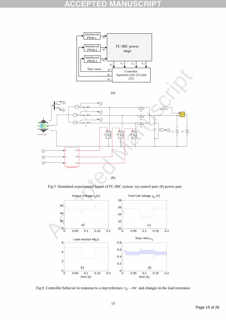
4. Simulation results
The controlled system is a three phase interleaved boost converter with the parameters listed
in Table 2. The experimental bench is described in Fig 5 and is simulated by using MATLAB
software. In this respect, all power components, including the FC, are simulated using the
relevant Matlab/Simulink power toolbox where current derivative limitation in the FC module
is taken into account. Then, the capability of the proposed controller to deal with such
limitation will be implicitly illustrated through the different simulation tests (e.g. Figs. 6, 7, 8
14).
4.1. Adaptive controller performances
The proposed adaptive control design is considered with the following numerical values of
design parameters which proved to be suitable:
4001 =k , 32 10=k , 4102 −×=γ and 3102.1 ×=α .
These have been selected using the common try-error method that consists in increasing the

Page 14 of 26
Accep
ted
Man
uscr
ipt
14
parameter values until a satisfactory compromise, between rapidity of responses and control
activity, is achieved. The behavior of such a system is illustrated in figures 6 to 8.
a) Regulator sensitivity to load uncertainty
Fig. 6 illustrates the behavior of controlled system with an output voltage reference
VVd 48= (which represents the DC bus voltage) and successive load step changes, the
resistance can change between 2.5Ω and 5Ω, yielding variation of 50% of the power of the
DC bus. As it can be seen, despite the load resistor uncertainty, the controller behavior is
satisfactory. Fig. 6(a) shows a tight voltage regulation under step load changes. Fig. 6(b)
shows the change of operation point of the fuel cell voltage, showing its high dependence on
the current. Fig. 6(c) depicts the load resistance 50% changes. Fig. 6(d) illustrates the duty
cycle variations, including a ripple characteristic of the sliding mode control, also known as
chattering [30].
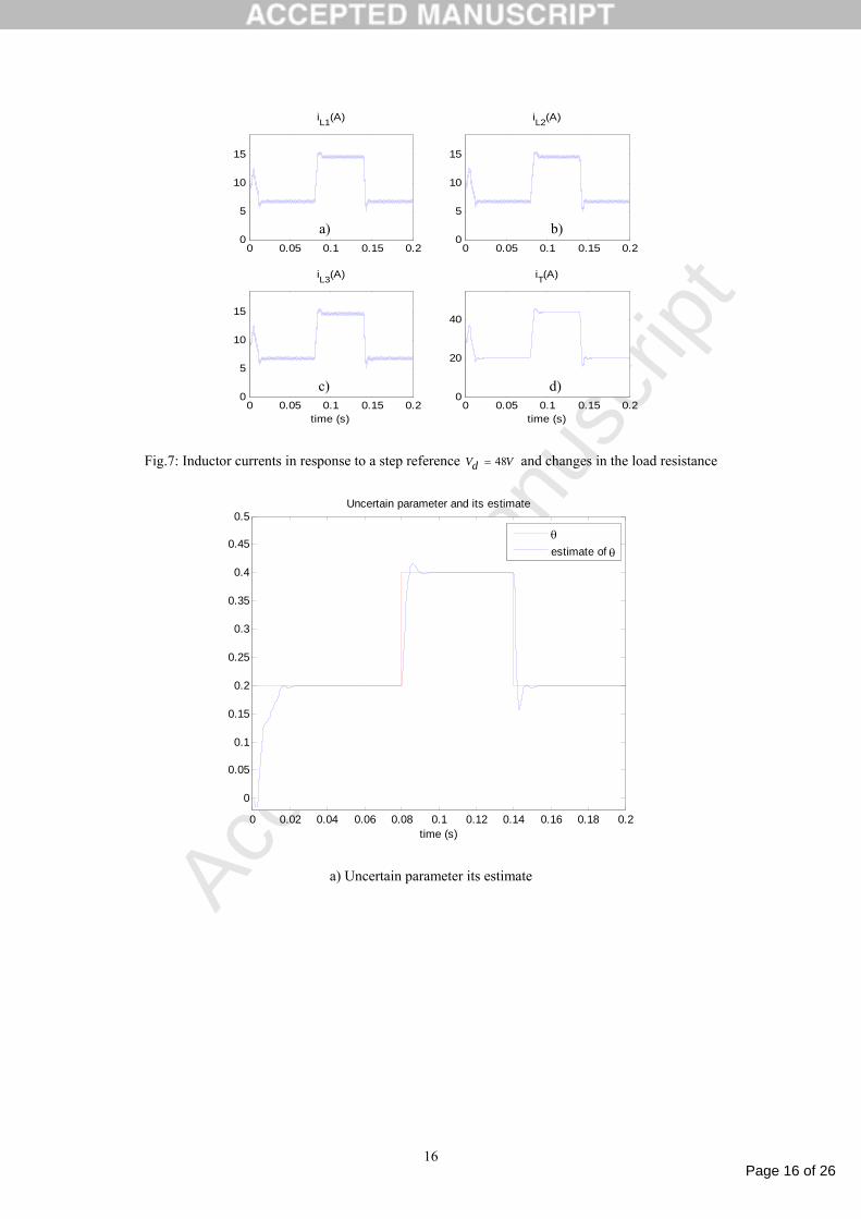
Fig. 7 shows an appropriate current sharing between the interleaved inductor currents for load
changes. Figs. 7(a)-(c) depicts the equal current sharing between the modules. Notice that Fig.
7(d) shows the ripple cancellation of the fuel cell current allowed by the interleaved inductor
currents.
Fig. 8 illustrates a perfect estimation of uncertain parameter, with negligible steady state error
and fast transient response.
Table 2: Parameters of the interleaved boost converter
Parameter Symbol Value
Number of phases N 3
Inductance value L mH2.2
Inductance ESR Lr Ωm20
Output Capacitor C Fµ1200
Switching frequency sf kHz10
Page 15 of 26
Accep
ted
Man
uscr
ipt
15
(a)
6I_T
5V_FC
4V_O
3IL_3
2IL_2
1IL_1
v+-
gm
CE
S3
g CE
S2
g CE
S1
R2R1
L3
L2
L1
U3
U2
U1
PWM1
PWM2
PWM3
Interleaved PWM
g
12
m
+
-
m
+
-
Fuel Cell Stack
D3
D2
D1
i+ -
i+ -
i+ -
C
4U1
3U2
2U3
1Switch-control
<Voltage>
<Current>
(b)
Fig.5: Simulated experimental bench of FC-IBC system: (a) control part; (b) power part.
0 0.05 0.1 0.15 0.20
20
40
60
Output Voltage v0(V)
0 0.05 0.1 0.15 0.220
22
24
26
28Fuel Cell voltage vin (V)
0 0.05 0.1 0.15 0.20
2
4
6Load resistor R(Ω )
time (s)0 0.05 0.1 0.15 0.2
0
0.2
0.4
0.6
0.8Duty ratio µ1
time (s)
Fig.6: Controller behavior in response to a step reference VdV 48= and changes in the load resistance
Controller: Equations (24), (21) and
(25)
Interleaved PWM-1
Interleaved PWM-2
Interleaved PWM-3
FC-IBC power stage
Duty ratios
µ1
µ2
µ3
u1
u2
u3 iL1 iL2 iL3 vO
a)
b)
c)
d)
Page 16 of 26
Accep
ted
Man
uscr
ipt
16
0 0.05 0.1 0.15 0.20
5
10
15
iL1(A)
0 0.05 0.1 0.15 0.20
5
10
15
iL2(A)
0 0.05 0.1 0.15 0.20
5
10
15
iL3(A)
time (s)0 0.05 0.1 0.15 0.2
0
20
40
iT(A)
time (s)
Fig.7: Inductor currents in response to a step reference VdV 48= and changes in the load resistance
0 0.02 0.04 0.06 0.08 0.1 0.12 0.14 0.16 0.18 0.2
0
0.05
0.1
0.15
0.2
0.25
0.3
0.35
0.4
0.45
0.5Uncertain parameter and its estimate
time (s)
θestimate of θ
a) Uncertain parameter its estimate
a) b)
c) d)

Page 17 of 26
Accep
ted
Man
uscr
ipt
17
0 0.02 0.04 0.06 0.08 0.1 0.12 0.14 0.16 0.18 0.2-0.2
-0.15
-0.1
-0.05
0
0.05
0.1
0.15
0.2
0.25Estimation error
time (s)
b) Estimation error
Fig.8: Controller estimation performances: a) uncertain parameter and its estimate, b) estimation error
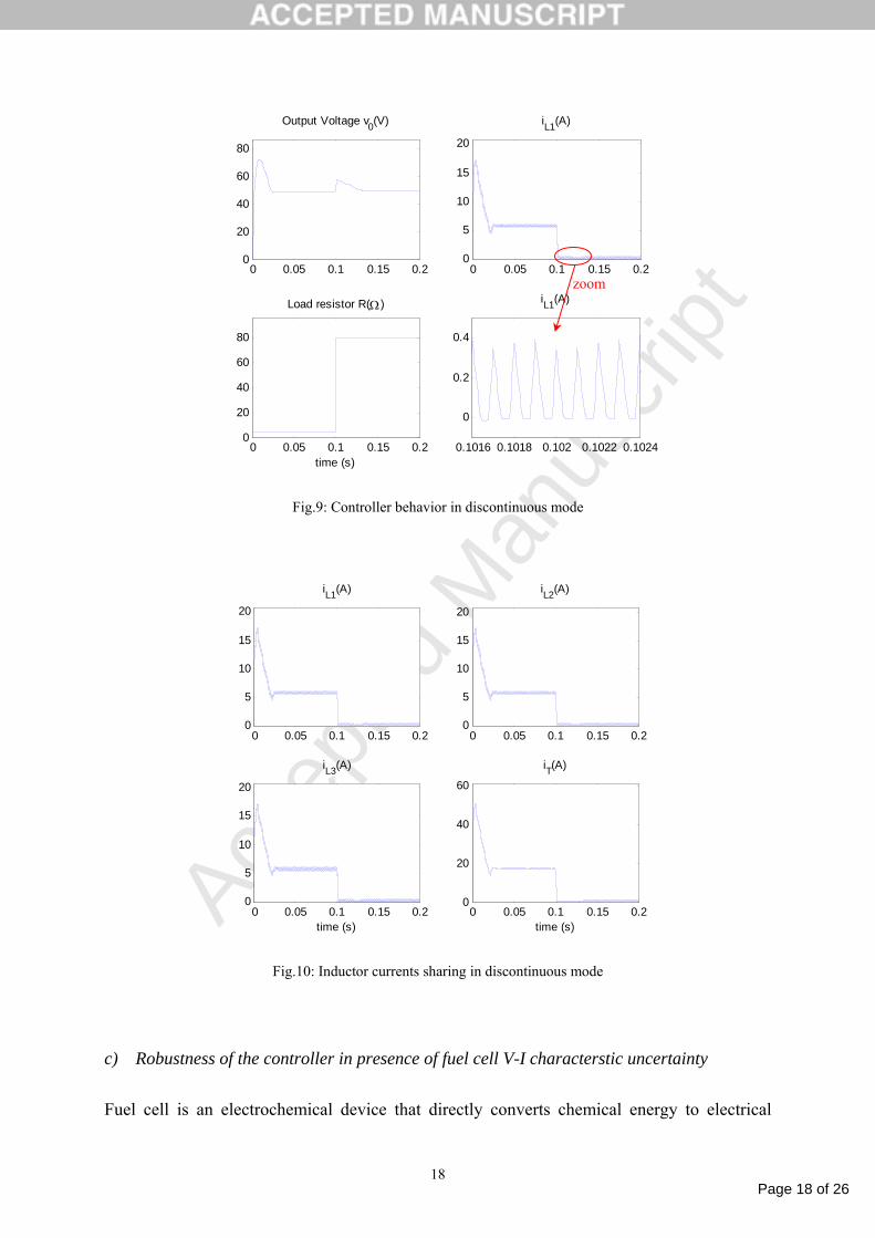
b) Controller behavior in presence of discontinuous conduction mode operation
In practice, dc-dc converters may enter into a discontinuous conduction mode operation. This
means that, in each switching period, the current may vanishe during a time interval. The
point is that such phenomenon is not accounted for in the control model (4), that is based on
in control design. Therefore, it is of interest to check whether the proposed adaptive controller
preserves its performances when it faces such converter behavior. To push the converter into
discontinuous mode operation, a sudden and drastic change of the load is produced at time
instant 0.1s (Fig. 9). Then, a drastic decrease of the current is produced that makes the
converter operates in discontinuous mode during an interval following the sudden load
change. This is illustrated making a zoom on the inductor current during the interval [101.6ms
102.4ms] (Fig. 10). Fig. 9 shows that the proposed controller is able to face discontinuous
mode keeping a tight output voltage regulation. Furthermore, Fig.10 shows that the current
sharing requirement, in presence of load changes, is also preserved despite the discontinuous
mode.
Page 18 of 26
Accep
ted
Man
uscr
ipt
18
0 0.05 0.1 0.15 0.20
20
40
60
80
Output Voltage v0(V)
0 0.05 0.1 0.15 0.20
5
10
15
20
iL1(A)
0 0.05 0.1 0.15 0.20
20
40
60
80
Load resistor R(Ω)
time (s)0.1016 0.1018 0.102 0.1022 0.1024
0
0.2
0.4
iL1(A)
Fig.9: Controller behavior in discontinuous mode
0 0.05 0.1 0.15 0.20
5
10
15
20
iL1(A)
0 0.05 0.1 0.15 0.20
5
10
15
20
iL2(A)
0 0.05 0.1 0.15 0.20
5
10
15
20
iL3(A)
time (s)0 0.05 0.1 0.15 0.2
0
20
40
60
iT(A)
time (s)
Fig.10: Inductor currents sharing in discontinuous mode
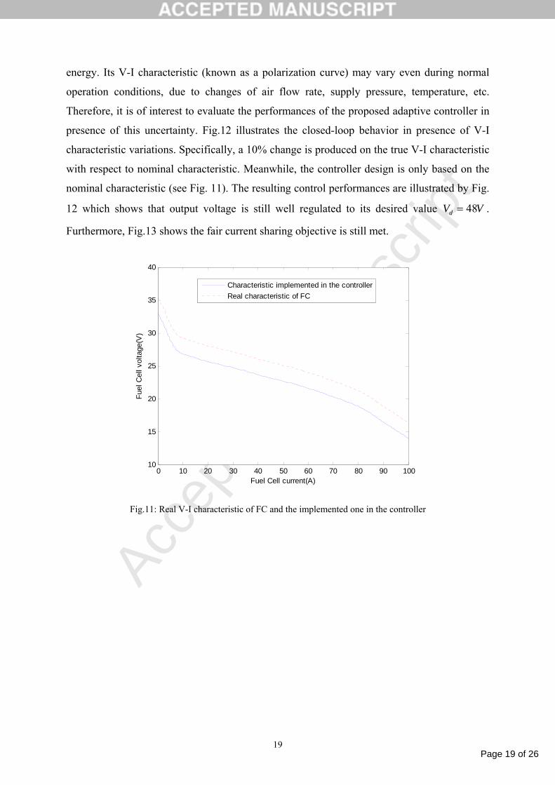
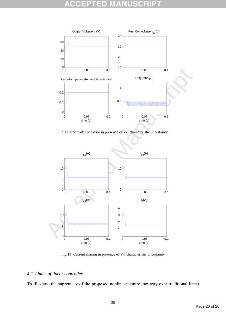
c) Robustness of the controller in presence of fuel cell V-I characterstic uncertainty
Fuel cell is an electrochemical device that directly converts chemical energy to electrical
zoom
Page 19 of 26
Accep
ted
Man
uscr
ipt
19
energy. Its V-I characteristic (known as a polarization curve) may vary even during normal
operation conditions, due to changes of air flow rate, supply pressure, temperature, etc.
Therefore, it is of interest to evaluate the performances of the proposed adaptive controller in
presence of this uncertainty. Fig.12 illustrates the closed-loop behavior in presence of V-I
characteristic variations. Specifically, a 10% change is produced on the true V-I characteristic
with respect to nominal characteristic. Meanwhile, the controller design is only based on the
nominal characteristic (see Fig. 11). The resulting control performances are illustrated by Fig.
12 which shows that output voltage is still well regulated to its desired value VVd 48= .
Furthermore, Fig.13 shows the fair current sharing objective is still met.
0 10 20 30 40 50 60 70 80 90 10010
15
20
25
30
35
40
Fuel Cell current(A)
Fuel
Cel
l vol
tage
(V)
Characteristic implemented in the controllerReal characteristic of FC
Fig.11: Real V-I characteristic of FC and the implemented one in the controller
Page 20 of 26
Accep
ted
Man
uscr
ipt
20
0 0.05 0.10
20
40
60
Output Voltage v0(V)
0 0.05 0.110
20
30
40Fuel Cell voltage vin (V)
0 0.05 0.10
0.1
0.2
Uncertain parameter and its estimate
time (s)0 0.05 0.1
0
0.5
1
Duty ratio µ1
time (s)
Fig.12: Controller behavior in presence of V-I characteristic uncertainty
0 0.05 0.10
5
10
iL1(A)
0 0.05 0.10
5
10
iL2(A)
0 0.05 0.10
5
10
iL3(A)
time (s)0 0.05 0.1
0
10
20
30
40
iT(A)
time (s)
Fig.13: Current sharing in presence of V-I characteristic uncertainty
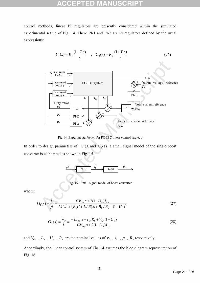
4.2. Limits of linear controller
To illustrate the supremacy of the proposed nonlinear control strategy over traditional linear
Page 21 of 26
Accep
ted
Man
uscr
ipt
21
control methods, linear PI regulators are presently considered within the simulated
experimental set up of Fig. 14. There PI-1 and PI-2 are PI regulators defined by the usual
expressions:
ssTKs )1()(C 1
11+
= ; s
sTKs )1()(C 222
+= (26)
Fig.14. Experimental bench for FC-IBC linear control strategy
In order to design parameters of )(C1 s and )(C2 s , a small signal model of the single boost
converter is elaborated as shown in Fig. 15.
Fig. 15 : Small signal model of boost converter
where:
221 )1(/)./(.)1(2.
~~
)(GnnLL
LnnOnL
URRsRLCRsLCIUsCVis
+++++−+
==µ
(27)
LnnOn
nOnLLnLn
L
O
IUsCVUVRIsLI
ivs
)1(2.)1(.
~~
)(G2 −+−+−−
== (28)
and nnLnOn RUIV , , , are the nominal values of Riv LO , , , µ , respectively.
Accordingly, the linear control system of Fig. 14 assumes the bloc diagram representation of
Fig. 16.
µ~ G1(s) G2(s) Li
~ Ov~
PI-1
Interleaved PWM-1
Interleaved PWM-2
Interleaved PWM-3
FC-IBC system
Duty ratios
µ1
µ2
µ3
u1
u2
u3 iL1 iL2 iL3
vO
Output voltage reference Vd
+-
1/3 +-PI-2
+-PI-2
+-PI-2
Total current reference ITref
Inductor current reference ILref
Page 22 of 26
Accep
ted
Man
uscr
ipt
22
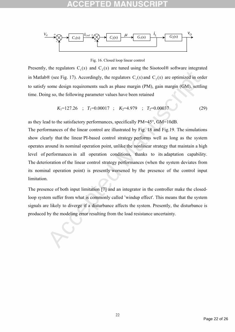
Fig. 16. Closed loop linear control
Presently, the regulators )(C1 s and )(C2 s are tuned using the Sisotool® software integrated
in Matlab® (see Fig. 17). Accordingly, the regulators )(C1 s and )(C2 s are optimized in order
to satisfy some design requirements such as phase margin (PM), gain margin (GM), settling
time. Doing so, the following parameter values have been retained
K1=127.26 ; T1=0.00017 ; K2=4.979 ; T2=0.00037 (29)
as they lead to the satisfactory performances, specifically PM=45°, GM=10dB.
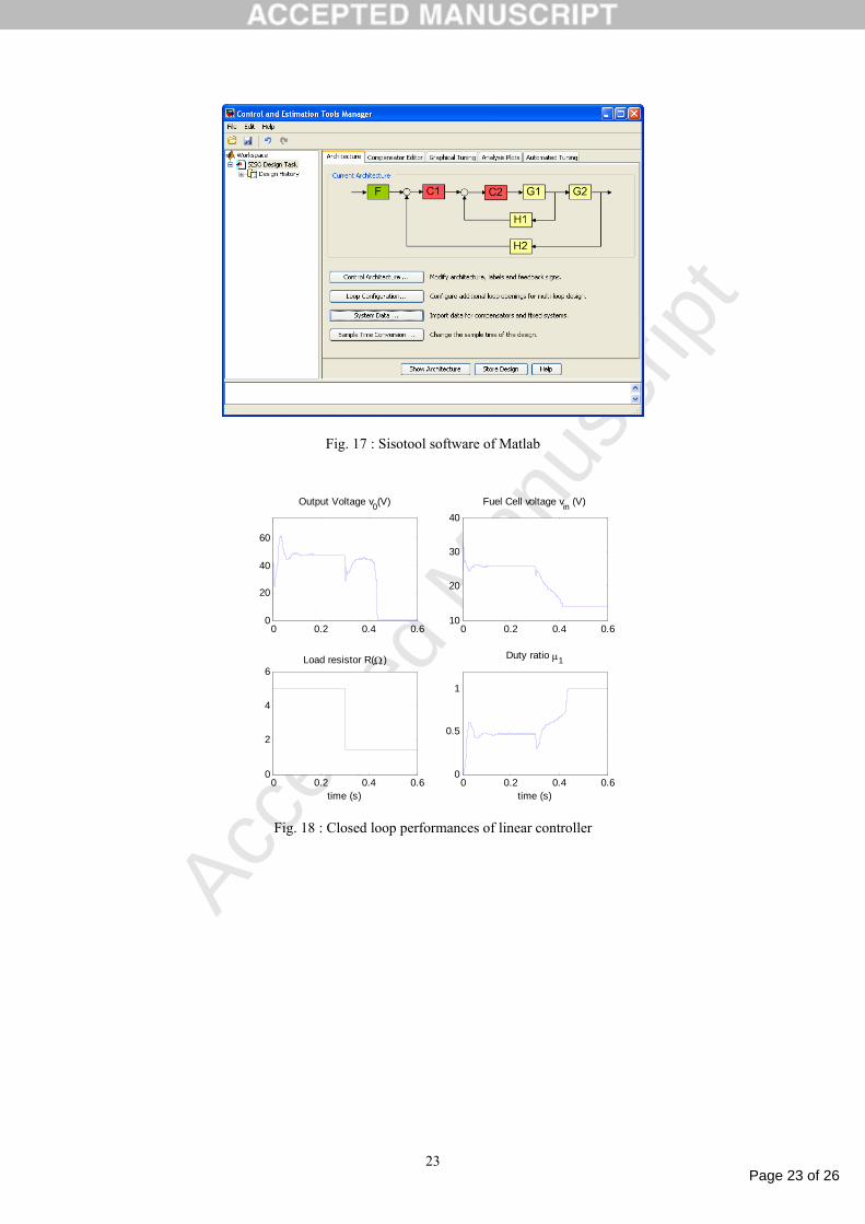
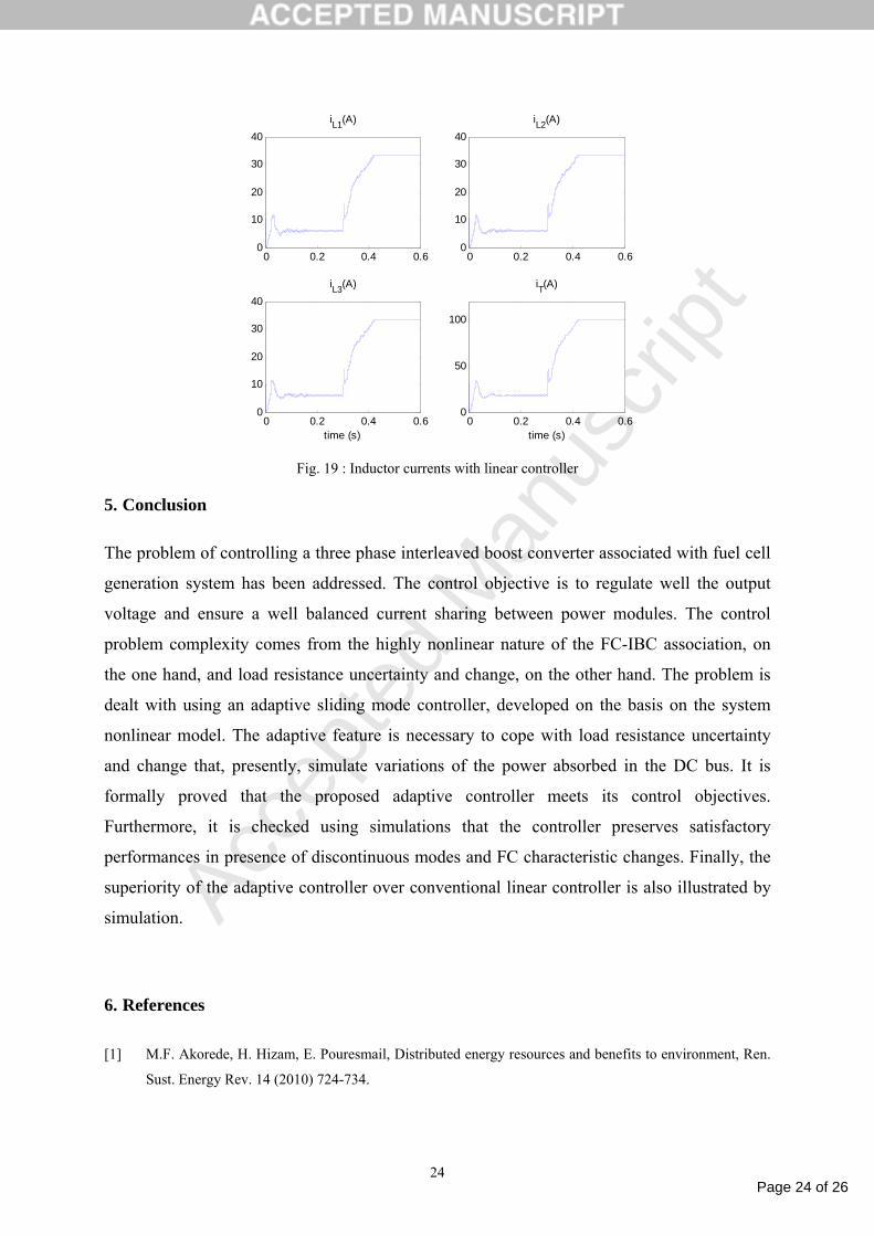
The performances of the linear control are illustrated by Fig. 18 and Fig.19. The simulations
show clearly that the linear PI-based control strategy performs well as long as the system
operates around its nominal operation point, unlike the nonlinear strategy that maintain a high
level of performances in all operation conditions, thanks to its adaptation capability.
The deterioration of the linear control strategy performances (when the system deviates from
its nominal operation point) is presently worsened by the presence of the control input
limitation.
The presence of both input limitation [7] and an integrator in the controller make the closed-
loop system suffer from what is commonly called ’windup effect'. This means that the system
signals are likely to diverge if a disturbance affects the system. Presently, the disturbance is
produced by the modeling error resulting from the load resistance uncertainty.
C2(s) Vd +
-
+
-
ILref µ G1(s) G2(s) Li Ov C1(s)
Page 23 of 26
Accep
ted
Man
uscr
ipt
23
Fig. 17 : Sisotool software of Matlab
0 0.2 0.4 0.60
20
40
60
Output Voltage v0(V)
0 0.2 0.4 0.610
20
30
40Fuel Cell voltage vin (V)
0 0.2 0.4 0.60
2
4
6Load resistor R(Ω)
time (s)0 0.2 0.4 0.6
0
0.5
1
Duty ratio µ1
time (s)
Fig. 18 : Closed loop performances of linear controller
Page 24 of 26
Accep
ted
Man
uscr
ipt
24
0 0.2 0.4 0.60
10
20
30
40iL1(A)
0 0.2 0.4 0.60
10
20
30
40iL2(A)
0 0.2 0.4 0.60
10
20
30
40iL3(A)
time (s)0 0.2 0.4 0.6
0
50
100
iT(A)
time (s)
Fig. 19 : Inductor currents with linear controller
5. Conclusion
The problem of controlling a three phase interleaved boost converter associated with fuel cell
generation system has been addressed. The control objective is to regulate well the output
voltage and ensure a well balanced current sharing between power modules. The control
problem complexity comes from the highly nonlinear nature of the FC-IBC association, on
the one hand, and load resistance uncertainty and change, on the other hand. The problem is
dealt with using an adaptive sliding mode controller, developed on the basis on the system
nonlinear model. The adaptive feature is necessary to cope with load resistance uncertainty
and change that, presently, simulate variations of the power absorbed in the DC bus. It is
formally proved that the proposed adaptive controller meets its control objectives.
Furthermore, it is checked using simulations that the controller preserves satisfactory
performances in presence of discontinuous modes and FC characteristic changes. Finally, the
superiority of the adaptive controller over conventional linear controller is also illustrated by
simulation.
6. References
[1] M.F. Akorede, H. Hizam, E. Pouresmail, Distributed energy resources and benefits to environment, Ren.
Sust. Energy Rev. 14 (2010) 724-734.
Page 25 of 26
Accep
ted
Man
uscr
ipt
25
[2] L.H. Chen, J.C. Hwang, S.N. Yeh, G.C. Yu, Analysis and Design of Four-Leg Fuel Cell Boost Converter,
in: Proc. of IEEE 32nd Annual Conference on Industrial Electronics (IECON’06), Paris, 2006, pp.4285-
4290.
[3] S. Dwari, L. Parsa, A Novel High Efficiency High Power Interleaved Coupled-Inductor Boost DC-DC
Converter for Hybrid and Fuel Cell Electric Vehicle, in Proc. of IEEE Vehicle Power and Propulsion
Conference ( VPPC), Arlington, 2007, pp.399-404.
[4] H. El Fadil, F. Giri, Backstepping Based Control of PWM DC-DC Boost Power Converters, Int. J. Elec.
Power Eng. 1(5) (2007) 479-485.
[5] H. El Fadil and F. Giri, Robust and Nonlinear Control of PWM DC-to-DC Boost Power Converters, in:
Proc. of the IEEE Power Electronics Specialists Conference (PESC'07), Vigo, 2007, pp. 407-412.
[6] H. El Fadil, F. Giri, Robust nonlinear adaptive control of multiphase synchronous buck power
converters, Elsevier Trans. Control Eng. Pract.17(11) (2009) 1245-1254.
[7] H. El Fadil, F. Giri , F.Z. Chaoui, O.El Maguiri, Accounting for Input limitation in Controlling Buck
Power Converters, IEEE Trans. Circ. Syst.-I 56(6) (2009) 1260-1271.
[8] H. El Fadil, F. Giri, O. El Maguiri, F.Z. Chaoui, Control of DC-DC power converters in the presence of
coil magnetic saturation, Elsevier Trans. Control Eng. Pract. 17(7) 2009 849-862.
[9] H. El Fadil, F. Giri, H. Ouadi, Accounting for coils magnetic saturation in controlling DC-DC power
converters, in: Proc. of the IEEE International Conference on Control Applications (CCA’06), Munich,
2006, pp.3163–3168.
[10] C. Gyu-Yeong, K. Hyun-Soo, L. Byoung-Kuk, L.Won-Yong, Design Consideration of Interleaved
Converters for Fuel Cell Applications, in: Proc. of International Conference on Electrical Machines and
Systems, Seoul, Korea, 2007, pp. 238 – 243.
[11] X. Haiping, E. Qiao, X. Guo, W. Xuhui, L. Kong , Analysis and Design of High Power Interleaved Boost
Converters for Fuel Cell Distributed Generation System, in: Proc of 36th IEEE Power Electronics
Specialists Conference (PESC'05) , Recife, 2005, pp.140-145.
[12] M. Harinee, V.S. Nagarajan, Dimple, R. Seyezhai, B.L. Mathur, Modeling and design of fuel cell based
two phase interleaved boost converter, in: Proc. of IEEE 1st International Conference on Electrical
Energy Systems (ICEES), Newport Beach, CA, 2011, pp.72-77.
[13] G. Hoogers, Fuel Cell Technology Handbook, CRC Press, Florida, 2003.
[14] M. Kabalo, B. Blunier, D. Bouquain, A. Miraoui, State-of-the-art of DC-DC converters for fuel cell
vehicles, in: Proc. of IEEE Vehicle Power and Propulsion conference (VPPC’10), Lille, 2010, pp.1-6.
[15] A. Khaligh, L. Zhihao, Battery Ultracapacitor Fuel Cell and Hybrid Energy Storage Systems for Electric
Hybrid Electric Fuel Cell and Plug-In Hybrid Electric Vehicles: State of the Art, IEEE Trans. Veh.
Technol. 58(6) (2010) 2806 - 2814
[16] X. Kong, A.M. Khambadkone, Analysis and Implementation of a High Efficiency, Interleaved Current-
Fed Full Bridge Converter for Fuel Cell System, IEEE Trans. Power Electron. 22(2) (2007) 543-550.
[17] P.T. Krein, J. Bentsman , R. M. Bass, B.Lesieutre, On the use of averaging for analysis of power
electronic system, IEEE Trans. Power Electron. 5(2) (1990) 182–190.
[18] M. Krstić, I. Kanellakopoulos, P. V. Kokotović, Nonlinear and adaptive control design, John Willy &
Sons, NY, 1995.
Page 26 of 26
Accep
ted
Man
uscr
ipt
26
[19] P.W. Lee, Y. S. Lee, D. K. W Cheng, X. C. Liu, Steady-state analysis of an interleaved boost converter
with coupled inductors, IEEE Trans. Ind. Electron. 47(4) (2000) 787-795.
[20] A. Newton, T. C. Green, D. Andrew, AC/DC power factor correction using interleaving boost and Cuk
converters, in: Proc. of IEE Power Electronics and Variable Speed Drives Conf., London, 2000, pp. 293-
298.
[21] E. Ortjohann, M. Lingemann, A. Mohd, W. Sinsukthavorn, A. Schmelter, N. Hamsic , D. A. Morton,
General Architecture for Modular Smart Inverters, in: Proc. of the IEEE International Symposium on
Industrial Electronics (ISIE’08), Cambridge, England, 2008, pp. 1525–1530.
[22] N. J. Park, D. S. Hyun, N interleaved boost converter with a novel ZVT cell using a single resonant
inductor for high power applications, in: Proc. IEEE conference on Industry Applications, Tampa FL,
2006, pp. 2157–2161.
[23] T. Phatiphat, B. Davat, Study of a multiphase interleaved step-up converter for fuel cell high power
applications, Energy Conv. Manag. 51(4) (2010) 826-832.
[24] J.T. Pukrushpan, H. Peng, A.G. Stefanopuolou, Control-oriented modeling and analysis for automotive
fuel cell system, J. Dyn. Sys. Meas. Control – Trans. ASME 126 (2004) 14–25.
[25] J.T. Pukrushpan, A.G. Stefanopoulou, H. Peng, Control of Fuel Cell Power Systems: Principles;
Modeling; Analysis and Feedback Design, Springer-Verlag, London, 2004.
[26] K. Rajashekara, Hybrid fuel-cell strategies for clean power generation, IEEE Trans. Ind. Appl. 41(2005)
682 – 689.
[27] H. B. Shin, J. G. Park, S. K. Chung, H. W. Lee, T. A. Lipo, Generalised steady-state analysis of
multiphase interleaved boost converter with coupled inductors, IEE Trans. Elec. Power Appl. 152(3)
(2005) 584-594.
[28] J.-J. E. Slotine, W. Li, Applied nonlinear control, Prentice Hall, Englewood Cliffs, NJ, 1991.
[29] P. Thounthong, P. Sethakul, S. Rael, B. Davat, Design and implementation of 2-phase interleaved boost
converter for fuel cell power source, in: Proc. of 4th IET Conference on Power Electronics Machines and
Drives (PEMD), York, 2008, pp.91-95.
[30] V.I. Utkin, Sliding Modes and Their Application in Variable Structure Systems, MIR, Moscow, 1978.
[31] M. Veerachary, T. Senjyu, K. Uezato, Maximum power point tracking of coupled inductor interleaved
boost converter supplied PV system, IEE Trans. Electr. Power Appl. 150 (2003) 71-80.
[32] X. Yu, M.R. Starke, L.M. Tolbert, B. Ozpineci, Fuel cell power conditioning for electric power
applications: a summary, IET Trans. Elec. Power Appl. 1(5) (2007) 643–656.
[33] M. T. Zhang, M. M. Jovanovic, F. C. Lee, Analysis and evaluation of interleaving techniques in forward
converters, IEEE Trans. Power Electron. 13(4) (1998) 690–698.