Embed Size (px)
Citation preview

1
Adaptive Tuned Vibration Absorbers: Design Principles, Concepts and
Physical Implementation
Philip Bonello University of Manchester
United Kingdom
1. Introduction
The tuned vibration absorber (TVA) has been used for vibration control purposes in many
sectors of civil/automotive/aerospace engineering for many decades since its inception by
(Ormondroyd & Den Hartog, 1928). A tuned vibration absorber (TVA), in its most generic
form, is an auxiliary system whose parameters can be tuned to suppress the vibration of a
host structure. The auxiliary system is commonly a spring-mass-damper system (or
equivalent) and the TVA suppresses the vibration at its point of attachment to the host
structure through the application of an interface force. The tuned frequency a of the TVA
is defined as its undamped natural frequency with its base (point of attachment) blocked.
The TVA can be used in two distinct ways, resulting in different optimal tuning criteria and
design requirements (von Flotow et al., 1994):
a. It can be tuned to suppress (dampen) the modal contribution from a specific troublesome
natural frequency s of the host structure over a wide band of excitation frequencies.
b. It can be tuned to suppress (neutralise) the vibration at a specific troublesome excitation
frequency , in which case it acts like a notch filter.
When used for application (a), the TVA referred to as a “tuned mass damper” (TMD). a is
optimally tuned to a value slightly lower than that of the targeted mode s and an optimal
level of damping needs to be designed into the absorber. When used for application (b), the
TVA is referred to as a “tuned vibration neutraliser” (TVN) (Brennan, 1997, Kidner &
Brennan, 1999) or “undamped TVA”. The optimal tuning condition is in this case is a
and the TVN suppresses the vibration over a very narrow bandwidth centred at the tuned
frequency. Total suppression of the vibration at this frequency is achieved when there is no
damping in the TVN. Deviation from the tuned condition (mistuning) degrades the performance of either variant of the TVA (von Flotow et al., 1994) and it can be shown that a mistuned vibration neutraliser could actually increase the vibration of its host structure (Brennan, 1997). To avoid mistuning, smart or adaptive tunable vibration absorbers (ATVAs) have been developed. Such devices are capable of retuning themselves in real time. Adaptive technology is especially important in the case of the TVN since the low damping requirement in the spring element can raise the host structure vibration to dangerous levels
www.intechopen.com

Vibration Analysis and Control – New Trends and Development
2
in the mistuned condition. In this case, mistuning can occur either due to a drift in the forcing frequency or due to a drift in tuned frequency caused by environmental factors (e.g. temperature change). Hence, a TVN needs to be adaptive to be practically useful.
At the heart of an ATVA is a means for adjusting the tuned frequency a in real time.
This is frequently done through the variation of the effective mechanical stiffness of the ATVA, although other means are possible. Whatever the retuning method used, the device should be tunable over an adequate range of frequencies, and the adjustment should be rapid and with minimum power requirement. The device must also be cheap and easy to manufacture. To maximise vibration attenuation, the retuning mechanism should add as little as possible to the redundant mass of the device and, in the case of the neutraliser, have a low structural damping (Brennan, 1997). The technical challenge is to design an adaptive device with such attributes. This chapter continues with a quantitative illustration of the basic design principles of both variants of the TVA. It will then present a comprehensive review of the various design concepts that have been presented for the ATVA, including the latest innovations contributed by the author. This section will cover the use of piezoelectric actuators, shape-memory alloys and servo-actuators within the smart structure of the ATVA. Control algorithms and their implementation through MATLAB® with SIMULINK® will also be discussed.
2. Basic design principles of TVA
With reference to Fig. 1a, the above-defined frequency a coincides exactly with the lowest
anti-resonance frequency of the attachment point receptance frequency response function
(FRF) of the undamped “free-body” TVA structure, AA Ar Y F , where AY and F are
complex amplitudes of Ay and the interface force f t , for harmonic vibration at circular
frequency . It is for this reason that, for the TVN, the condition a defines optimal
tuning. For excitation frequencies below the first non-zero resonance frequency m of AAr , the absorber can be represented by the equivalent two-degree-of-freedom model
shown in Fig. 1b (Bonello & Groves, 2009). Fig. 1b shows that the absorber mass am is split
into an effective mass ,a eff am Rm and a redundant mass , 1a red am R m . The latter mass
simply adds to the host structure. The effective part of the absorber is the single-degree-of-
freedom system constituted by mass ,a effm , the spring of stiffness 2,a a a effk m and a
damping element. In the case of a TMD, where damping is deliberately designed into the
device, it is preferable to represent it by viscous damper of frequency-independent
coefficient ac . In the case of a TVN, where the damping is an unwanted inherent feature of
the spring element, it is best represented by a structural damping mechanism of loss factor
a , for which the equivalent viscous damping coefficient is a ak . The method for
deriving the equivalent two-degree-freedom is detailed in Section 4.1.
2.1 Tuned mass damper
The purpose of the TMD is to dampen a particular resonance peak of the FRF APr
connecting the response at A to an external force pf t applied to the host structure at some
arbitrary point P. It is useful for applications where the excitation has a broad frequency
spectrum containing the targeted mode. The damping in the original host structure (i.e. the
www.intechopen.com

Adaptive Tuned Vibration Absorbers: Design Principles, Concepts and Physical Implementation
3
structure prior to the addition of the TMD) is commonly assumed to be negligible relative to
that introduced by the TMD. Suppose the TMD is targeted at the sth mode of the original
host structure. Let s be the frequency of this mode and sA denote the value of the
corresponding mass-normalised mode-shape at the degree of freedom being targeted (e.g.
the vertical displacement at A in Fig. 1). Then, from standard modal theory (Ewins, 1984),
the contribution of the targeted mode to the dynamics of the original host structure at the
targeted degree of freedom can be represented as the simple mass-spring system of mass 2
1s s
A AM and stiffness 2s ssA AK M (see Fig. 2(a)). The dynamics of the original host
structure at the targeted degree of freedom can be accurately modelled in this form for
excitation frequencies in the vicinity of s , where the targeted mode is dominant.
Addition of the TMD in Fig. 1b to the system in Fig. 2(a) results in the system in Fig. 2(b).
Notice that original host structure modal mass sAM needs to be readjusted to
,s
a redAM m ,
to account for the addition of the redundant absorber mass to the host structure. The
harmonic analysis of the systems in Figs. 2(a,b) (i.e. analysis with jRe e tP Pf F ) then
gives a modal approximation of APr , denoted by sAPr , which is accurate for
frequencies in the vicinity of s .
Fig. 1. Generic TVA
Fig. 2. Dynamic modal model of the host structure without/with TMD for frequencies in
the vicinity of s
sAK
ay
reda
s
A mM , tfPs
A
s
P
ak ac
effam ,
Ay sAM
sAK
Ay
tfPs
A
s
P
(a) Host structure (b) Host structure with TMD
www.intechopen.com

Vibration Analysis and Control – New Trends and Development
4
sAPr can be dampened by adapting the harmonic analysis in (Den Hartog, 1956) to the
system in Fig. 2(b). The optimal tuning condition is found to be:
1
1
opta
s
(1)
where
,s s
s s a redA AM M m , , ,s
a eff a redAm M m (2)
The viscous damping coefficient is given by:
,2a a a eff ac m (3)
The optimal value of the viscous damping ratio a is given by (Den Hartog, 1956):
3
3
8 1opta
(4)
The optimisation of the modulus of sAPr is illustrated in Fig. 3. The introduction of the
TMD splits the original host structure resonance peak into two peaks separated by an anti-
resonance. Points M and N are referred to as the ‘fixed points’ since, for given and a ,
the function sAPr of the modified structure passes through them regardless of the value
of a . The optimal tuning condition of eq. (1) ensures that the fixed points are level with
each other (this is the case illustrated in Fig. 3). With this condition in place, the optimal
damping condition of eq. (4) ensures that the peaks of sAPr coincide as closely as
possible with the fixed points. The height of these optimised peaks is approximately
inversely proportional to . As an illustration of the effect of a TMD on a multimodal (i.e. continuous) system, consider a
TMD attached to the tip of a cantilever and tuned to attenuate its second flexural mode (Fig.
4). The cantilever OA is of length 1m and made of steel (Young Modulus 200 GN/m2,
density 7850 kg/m2) of circular section with diameter 3cm.
Assuming an Euler-Bernoulli beam model, an eigenvalue analysis yields 2 2 132.8
Hz, 21.387AM kg. The mass ratio is taken as 2%. For simplicity, the TMD is assumed to
have no redundant mass. The TMD parameters were computed according to the above
formulae. The receptances AP A Pr Y F of the system with and without the TMD were
evaluated using the Dynamic Stiffness Method (Bonello & Brennan, 2001) and shown in Fig.
5, where the dampening of the targeted resonance is clearly evident.
Fig. 6 illustrates the effect of mistuning i.e. deviation from the tuned condition of eq. (1). The
stiffness ak of the TMD was varied such that it was mistuned by 10% i.e. a was set to
1.1opta , with ac kept the same as the optimal case of Fig. 5 (considering eqs. (3) and (4), this
means that a of the mistuned case in Fig. 6 is not opta ). It is clear from Fig. 6 that a slight
mistuning produces significant deterioration of the TMD performance.
www.intechopen.com

Adaptive Tuned Vibration Absorbers: Design Principles, Concepts and Physical Implementation
5
0.8 0.85 0.9 0.95 1 1.05 1.1 1.15 1.20
10
20
30
40
50
Fig. 3. Effect of damping on the modal approximation of the attachment point FRF (case
shown is for the tuned condition, eq. (1), with 0.02
Fig. 4. TMD attached to a cantilever
0 50 100 150 200 250 300 350 400
10-6
10-4
10-2
Fig. 5. Effect of TMD targeted against the second flexural mode of cantilever in Figure 4: original system (dashed line); with TMD (solid line)
ak ac
effam ,
tPp FfjeRe
O A P
Ay0.4m 0.6m
APr
(m/N)
2 (Hz)
0a s
APr
s
a M N
No TMD
s
As
P
s
A K
optaa
optaa 2
optaa 5.0
www.intechopen.com
Vibration Analysis and Control – New Trends and Development
6
0 50 100 150 200 250 300 350 400
10-6
10-4
10-2
Fig. 6. Effect of a mistuned TMD on cantilever in Figure 4: TMD optimally tuned and damped as per eqs. (1) and (4) (solid line); 10% mistuned TMD (dotted line)
Finally, it is worth mentioning that a similar effect to the TMD can be achieved through an electrical analogue, wherein the auxiliary system is a piezoelectric shunt circuit (Park, 2002). In such an ‘electrical’ TVA, a piezoelectric patch is bonded to the host structure and connected across an external inductor-resistor circuit. The piezoelectric patch is used to convert the vibration energy of the host structure into electrical energy and introduces a capacitor effect into the circuit, turning it into an L-C-R circuit. The electrical energy is then dissipated most efficiently as heat through the resistor when the electrical resonance produced by the LC components is close to the frequency of the targeted mode and the resistor has an optimum value. One major disadvantage of the electrical TVA is the difficulty in deriving the transfer function of the modified system (on which the optimisation is based); the difficulty increases with the complexity of the host structure. For this reason the electrical TVA has typically been restricted to simple host structures like cantilevers (e.g. Park, 2002). In contrast, the classical theory of the mechanical TMD is readily applicable to any arbitrary host structure since the only host structure data it requires are the frequency and modal mass of the targeted mode.
2.2 Tuned vibration neutraliser
The purpose of the TVN is to plant an anti-resonance in the FRF APr at some particular
chosen value of the excitation frequency . Hence, the TVN is typically used for
applications where the excitation is entirely, or mainly, at a single frequency (i.e. harmonic).
For example, suppose that it is required to cancel the tip vibration of the above considered
cantilever (Fig. 4) at a frequency of 50 Hz. The optimal condition for a TVN is
a (5)
Hence, in this example, a is optimally set to 100 . Neglecting the redundant TVA mass
and assuming an effective mass of the absorber, the absorber stiffness is calculated
accordingly. The effect of the TVN is illustrated in Fig. 7, where the absorber mass is
assumed to be 2% of the total mass of the beam. It is seen that an anti-resonance is
introduced at the desired frequency, in addition to a resonance at a slightly higher
APr
(m/N)
2 (Hz)
www.intechopen.com

Adaptive Tuned Vibration Absorbers: Design Principles, Concepts and Physical Implementation
7
frequency (52 Hz) (the difference between the anti-resonance and resonance frequencies is
found to increase with the effective TVN mass). (Brennan, 1997) defines the attenuation D provided by a TVN for harmonic excitation as the ratio of the vibration amplitude at A without the TVN to the amplitude there with the TVN attached and optimally tuned:
free
TVN , opt
A
A
YD
Y (6)
In the absence of damping in the absorber D (complete attenuation). The attenuation
degrades with increasing absorber damping a (since this reduces the depth of the anti-
resonance in Fig. 7). Also, for given absorber damping, the TVA’s attenuating capability
degrades as ,a effm is reduced. In fact, for a host structure that is a rigid machine of mass M
mounted on soft isolators, (Brennan , 1997) showed that
aD (7)
where
, ,a eff a redm M m (8)
Deviation from the optimally tuned condition a (mistuning) can occur due to a change
in the excitation frequency (e.g. a change in operating speed of rotating machinery). It is
evident from Fig. 7 that even a slight mistuning will drastically degrade the performance of
the TVN. In fact, as can be seen in Fig. 7, if the excitation frequency drifts above a then the
vibration neutraliser actually increases the vibration of its host structure due to the extra
resonance it introduced into the system. This extra resonance is itself made more
pronounced by the low damping requirement.
0 50 100 150 200 250 300 350 400
10-6
10-4
10-2
Fig. 7. Effect of TVN tuned to an excitation frequency of 50Hz on the cantilever in Fig. 4: original system (dashed line); with TVN (solid line)
2 (Hz)
APr
(m/N)
a
www.intechopen.com

Vibration Analysis and Control – New Trends and Development
8
3. Adaptive tuned vibration absorbers – an overview
“Tuning” a TVA involves making the appropriate adjustment of a and this is done
through an adjustment in one or more properties of the TVA structure. Mistuning is avoided
through the use of adaptive (or “smart”) tuneable vibration absorbers (ATVAs) which can
automatically perform the necessary adjustment in real time (von Flotow et al., 1994,
Brennan et al., 2004a). As demonstrated in the previous section, mistuning is a far more
serious issue for the TVN, since the requirement for low absorber damping can raise the
host structure vibration to dangerous levels in the mistuned condition. It is for this reason
that adaptive technology has been mainly developed in the context of the TVN. The ATVAs
considered in the remainder of the chapter will therefore exclusively be vibration neutralisers.
In the context of the TVN, adaptive tuning of the device involves maintaining the condition
a in the presence of variable conditions (typically a time-varying excitation frequency
, in which case the antiresonance in Fig. 7 is shifted in real time along the frequency axis,
in accordance to the current value of the excitation frequency). The challenge for ATVA
designers is to produce a device with the following attributes: i. low structural damping; ii. any actuating mechanism to retune the device should add as little as possible to the
redundant mass; iii. the device should be tuneable over a wide range of frequencies; iv. retuning should be rapid and with minimum power requirement; v. the device should be cheap and easy to design and manufacture. Various design concepts for ATVAs have been proposed (von Flotow et al., 1994, Brennan et al., 2004a). One early variable stiffness element used in a vibration absorber was described in (Longbottom et al., 1990). A mass was sandwiched between a pair of pneumatic rubber bellows (Fig. 8) and the stiffness was adjusted by changing the air pressure inside the bellows. Further work on this device by (Long et al., 1998) resulted in a means of automatically adjusting the stiffness. However, the high amount of damping introduced by the rubber bellows was a major disadvantage.
Fig. 8. Pneumatic rubber bellows ATVA (Brennan et al., 2004b)
www.intechopen.com

Adaptive Tuned Vibration Absorbers: Design Principles, Concepts and Physical Implementation
9
One recent strategy for adaptation, by (Rustighi et al., 2005), was to utilise the variation with temperature of the Young Modulus of a beam-like ATVA made of a shape memory alloy (SMA) conductor (Fig. 9). The SMA wire formed a double cantilever, projecting from either side of the central attachment point to the host structure. The ATVA stiffness was controlled by adjusting the current through the wire. Despite being strong in attributes (i), (ii) and (v) above, this device could only achieve a maximum variation of around 20% in tuned frequency, taking as long as 2 minutes with a 9A current to do so (Brennan et al., 2004a, Rustighi et al., 2005).
Fig. 9. Shape memory alloy ATVA (Rustighi et al., 2005)
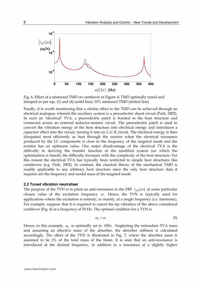
Another recent approach, by (Bonello et al., 2005) was to utilise a mass-spring ATVA in which the stiffness element was composed of parallel curved beams in longitudinal compression (Fig. 10). The longitudinal stiffness was controlled by adjusting the curvature through piezo-ceramic actuators bonded to the beams. This device was capable of very rapid tuning over a frequency range 36-56 Hz (56% variation). However, this design concept was inherently limited to low frequency applications as a result of inertia effects in the curved beams (Bonello et al., 2005). Other works have focused on the use of a beam-like ATVA controlled through servo-actuation. This concept remains the best approach for applications requiring a wide tuning frequency range (Carneal et al., 2004). Figs. 11-15 show various such ATVA designs. The “moveable-supports” ATVA in Fig. 11 was patented by (Hong & Ryu, 1985). It consisted of a beam with a mass attached to its centre and supports that could be moved relative to each
other, thereby altering a .
(Brennan, 2000) performed a theoretical study of the tuning frequency characteristics of the designs in Figs. 12, 13. In Fig. 12, the ATVA beam is composed of two beams and the effective stiffness of the ATVA is adjusted by pushing apart the two constituent beams at the centre, thereby altering the ATVA beam cross-section. Such a device was built and tested in (Kidner et al., 2002), where a maximum adjustment of 35% in tuned frequency was achieved. This concept appears to provide the most rapid tuning of all beam-like designs in Figs. 11-15 since the actuator is required to move the least distance to achieve a given change
www.intechopen.com
Vibration Analysis and Control – New Trends and Development
10
in a . However, the actuator has to work against much larger forces and the variability in
a is clearly limited by the maximum deformation that the constituent beams can withstand as they are being prised apart. Through elementary analysis, (Brennan, 2000) predicted that a considerably greater tuning range is achievable through the two alternative designs in Fig. 13 (“moveable beam” or “moveable masses”). In the “moveable beam” approach the masses are fixed relative to the beam and the beam lengthens or shortens. This device does not appear to have been built and would require some form of telescoping beam. The “moveable-masses” concept is more feasible: the beam is of fixed length and tuning is achieved by repositioning the attached masses. (Von Flotow et al., 1994) describes devices that appear to match this latter description in operation on the Boeing Chinook helicopter, although the details available are very sketchy.
Fig. 10. ATVA with variable-curvature piezo-actuated beams (Bonello et al., 2005)
Fig. 11. Servo-actuated beam ATVA: moveable-supports, conventional design (Hong & Ryu, 1985)
www.intechopen.com

Adaptive Tuned Vibration Absorbers: Design Principles, Concepts and Physical Implementation
11
In all devices of Figs. 11-13, the actuator is a permanently redundant mass that degrades the attenuating capacity of the ATVA (eq. (7, 8)). This limitation was overcome by (Carneal et al., 2004) who improved the “moveable-supports” concept of (Hong & Ryu, 1985) by incorporating the actuator into the central mass supported by the beam (Fig. 14). This necessitated the use of a “V-Type” undercarriage. The design of this undercarriage (and the one used in Fig. 11) clearly warrants careful consideration. It should be sufficiently rigid so as to avoid introducing unwanted dynamics that would interfere with ATVA operation. Moreover, it needs to be as light as possible to minimise the redundant mass. A far simpler approach would be to utilise a moveable-masses ATVA with actuators incorporated into the masses, as illustrated in Fig. 15, where the device simply attaches directly to the host structure at its centre. Such a novel device was proposed by (Bonello & Groves, 2009). Apart from the constructional simplicity, this concept was shown to provide superior ATVA performance. Another important contribution of (Bonello & Groves, 2009) was the derivation of the effective mass and tuned frequency characteristics of the moveable-supports and moveable-masses ATVA. This enables the designer to quantify their expected performance for any given application. The derivation of the effective mass of the beam-like ATVAs in Figs. 11-15 requires the derivation of their equivalent two-degree-of-freedom model (Fig. 1b). Such analysis is very important when one considers that, for the devices in Fig. 11-15 (with the possible exception of Fig. 12), the effective mass proportion R will vary as the ATVA is retuned. Although (Carneal et al., 2004) describe their actuator-incorporated mass (Fig. 14) as the “active mass” of the absorber, its degree of activity is actually dependent on the setting of the ATVA. The same can be said of the moveable-masses concept (Fig. 15). With the supports or masses fully retracted in Figs. 14 and 15, the attached masses clearly become entirely redundant and the effective mass proportion R in Fig. 1b is then entirely contributed by the beam itself. This means that, as the ATVA retunes itself, the attenuation it provides will vary due to the consequent variation in (eqs. (7, 8)). Hence, the knowledge of an
“effective mass characteristic” of a moveable-supports or moveable-masses ATVA is important since it would allow the designer to quantify the expected attenuation provided by an ATVA over a range of frequencies for any given application.
4. ATVA analysis
The aims of this section are two-fold: (i) to illustrate the derivation of the effective mass and tuned frequency characteristics of moveable-supports and moveable-masses ATVAs (Figs. 14 and 15); (ii) to illustrate the physical implementation and testing of the beam-like ATVA with actuator-incorporated moveable masses (Fig. 15). This latter covers the adaptation logic control. The material in this section is based on the work in (Bonello & Groves, 2009), from which further details can be obtained.
4.1 Effective mass and tuned frequency characteristics
Fig. 16 shows the two alternative types of ATVA considered. It shall be assumed that the
beam supports of the device in Fig. 16b are simple supports. Let A denote the point/points
of attachment of the beam to the host structure and B denote the point/points of attachment
of the mass/masses. The aim of the following analysis is the determination of the fractional
change in tuned frequency a and the variation of the effective mass proportion R (Fig. 1b)
as the setting x x L of the actual systems in Fig. 16 is varied. Hence, for this purpose,
damping can be omitted from the analysis without loss of accuracy.
www.intechopen.com

Vibration Analysis and Control – New Trends and Development
12
Fig. 12. Servo-actuated beam-like ATVA: adjustable beam-cross-section ATVA (Brennan, 2000, Kidner et al., 2002)
Fig. 13. Servo-actuated beam-like ATVA: moveable-beam or moveable-masses ATVA (Brennan, 2000)
Fig. 14. Servo-actuated beam-like ATVA: moveable supports, “V-Type” design ATVA (Carneal et al., 2004)
www.intechopen.com

Adaptive Tuned Vibration Absorbers: Design Principles, Concepts and Physical Implementation
13
Fig. 15. Servo-actuated beam-like ATVA: actuator-incorporated moveable masses ATVA (Bonello & Groves, 2009)
Fig. 16. Free-body schematics of two alternative designs for an actuator-incorporated mass ATVA
In either case the system will be regarded as comprising a beam acted upon by: (i) the reaction forces from the lumped mass attachments at B; (ii) the reaction force from the host.
If the latter force is jRe e tf t F , then the response at any point Q on the beam is
jRe e tQ Qy t Y . Following the analysis in (Bonello & Groves, 2009), the expression for
the receptance of the TVA at its point of attachment to the structure is:
2
21
2 22 2
2
212 2 2
2 23,5,....
1
1 11
1 1
AAA
b
AA BB BA AB
kK B
Bk k
Yr
F m
(9)
A
B B tf
B
A A
2tf 2tf
L2
x2
L2
x2
(a) Moveable masses (b) Moveable supports (‘V’-type)
www.intechopen.com

Vibration Analysis and Control – New Trends and Development
14
where:
att
b
m
m ,
1
, 1
kk
, 2 2
1,3,5,....
k kKQ S
QSk k
(10a-d)
In the above expressions attm is the sum of the attached masses at B (for moveable masses)
or simply the mass at B (for moveable supports) and bm is the mass of the beam alone. kQ , k
S are the kth flexural non-dimensional mode-shape functions evaluated at arbitrary points
Q, S and k is the kth flexural natural frequency. These modal parameters pertain to the
plain beam (i.e. without lumped mass attachment) under free-free conditions. Notice that
only the symmetric modes are considered due to the symmetry of the systems in Fig. 16. The
expression in eq. (9) is exact for K but, for a given upper limit of the non-dimensional
excitation frequency , will be virtually exact for a sufficiently large finite value of K
(corresponding to a total of 1 2K symmetric modes). For the moveable masses
absorber, kA is fixed and k
B is variable; for the moveable supports absorber kB is fixed
and kA is variable. If the Euler-Bernoulli beam model is assumed, then the free-free mode-
shape function values tabulated by (Bishop & Johnson, 1960) can be used. In this case, from
eq. (9), it is clear that the non-dimensional receptance function
21, ,AA b AAr x m r (11)
is totally independent of the actual material and geometrical properties for either ATVA in Fig. 16.
For given x and , the lowest non-dimensional anti-resonance 1a a (i.e. the tuned
frequency of the device) is obtained by finding the lowest value of for which the
numerator of eq. (9) is 0:
2 22 2
1 11 0AA BB BA AB
(12)
Similarly, the lowest non-dimensional resonance 1m m is obtained by finding the
lowest value of for which the denominator of eq. (9) is 0:
2
212 2 2
2 23,5,....
1 1 0
kK B
Bk k
(13)
For any given K, the frequencies a , m can be found by an iteration technique using as
initial approximations the corresponding roots 1a K
, 1m K
obtained for 1K . From eqs.
(12, 13) it can be shown that:
1 2 2
1
1 1 2a K
A B A B
, 1 2
1
1 1m K
B
(14a,b)
www.intechopen.com

Adaptive Tuned Vibration Absorbers: Design Principles, Concepts and Physical Implementation
15
High accuracy is guaranteed here by solving the frequencies a , m for 39K , which
means that 20 symmetric free-free plain beam flexural modes were considered. Now, for the equivalent two-degree-of-freedom system in Fig. 1b, one can write the attachment point receptance as (Kidner & Brennan, 1997):
2 2
2-DOF 2 2 2, , ,1
aAA
a red a eff a red a
rm m m
(15)
where
,a eff am Rm , , 1a red am R m , 1a bm m (16a-c)
The non-zero resonance of the function in eq. (15) is given by:
, ,2-DOF1m a a eff a redm m (17)
For equivalence, 2-DOFm m in eq. (17). Hence, by substituting this condition and eqs.
(16a,b) into eq. (17), an expression can be obtained for the proportion R of the total absorber
mass am that is effective in vibration attenuation:
2, 1 a mR x (18)
…where a , m are the roots of eqs. (12, 13). Also, from eq. (15) and eqs. (16), the non-
dimensional attachment point receptance of the equivalent system can be written as:
2 221 2 2 22-DOF 2-DOF
, ,1 1
aAA b AA
a
r x m rR
(19)
The equivalent two-degree-of-freedom model is verified in Fig. 17 against the exact theory
governing the actual (continuous) ATVA structures of Fig. 16 for 5 and two given
settings 0.25x , 0.5 . For each setting of x the corresponding values of a and R were
calculated using eqs. (12, 13, 18) and used to plot the function 2-DOF
, ,AAr x in eq. (19).
Comparison with the exact receptance , ,AAr x (computed from eqs. (9) and (11)) shows
that the equivalent two-degree-of-freedom system is a satisfactory representation of the
actual systems in Fig. 16 over a frequency range which contains the operational frequency of
the ATVA ( a ).
Next, using eqs. (12, 13, 18), the variations of a and R with ATVA setting x for various
fixed values of are investigated for both types of ATVA in Fig. 16. The resulting
characteristics are depicted in Fig. 18. With reference to Fig. 18a, it is evident that, as is
increased, the tuning frequency characteristics of both types of ATVA approach each other.
Moreover, for 1 , both types of ATVA give roughly the same overall useable variation in
a relative to 1a x
. The moveable-supports ATVA characteristics in Fig. 18a have a peak
(which is more prominent for lower values) that gives the impression of a greater
variation in a than the moveable-masses ATVA. However, this is a “red herring” since
www.intechopen.com

Vibration Analysis and Control – New Trends and Development
16
these peaks coincide with a stark dip to zero in the effective mass proportion R of the
moveable-supports ATVA, as can be seen in Fig. 18b. These troughs in R are explained by
the fact that, for given , the free body resonance m of the moveable-supports ATVA (i.e.
the resonance of the free-free beam with central mass attached) is fixed (i.e. independent of
x ), as can be seen from Figs. 17c,d. Hence, the nodes of the associated mode-shape are fixed
in position so that when the setting x is such that the attachment points A of the moveable-
supports ATVA coincide with these nodes, this ATVA becomes totally useless (i.e.
attenuation 0D , eq. (7)).
Fig. 17. Verification of equivalent two-degree-of-freedom model - non-dimensional attachment point receptance plotted against non-dimensional excitation frequency for two
settings of the ATVAs in Figure 3 with 5 : exact, through eqs. (9) and (11) (――――);
equivalent 2-degree-of-freedom model, from eq. (19 ) (▪▪▪▪▪▪▪▪▪)
The moveable-masses ATVA does not suffer from this problem, and consequently has vastly superior effective mass characteristics, as evident from Fig. 18b. From eqs. (16a, b), one can rewrite the attenuation D in eq. (8) as:
www.intechopen.com

Adaptive Tuned Vibration Absorbers: Design Principles, Concepts and Physical Implementation
17
1
1a a
RD
R M m (20)
It is evident from Fig. 18b and eq. (20) that the degree of attenuation D provided by a given moveable-supports ATVA in any given application undergoes considerable variability over its tuning frequency range, dipping to zero at a critical tuned frequency. On the other hand, the moveable-masses ATVA can be tuned over a comparable tuning frequency range while providing significantly superior vibration attenuation.
Fig. 18. Tuned frequency and effective mass characteristics for moveable-masses ATVA
www.intechopen.com

Vibration Analysis and Control – New Trends and Development
18
4.2 Physical implementation and testing Fig. 19 shows the moveable-masses ATVA with motor-incorporated masses that was built in (Bonello & Groves, 2009) to lend validation to the theory of the previous section and demonstrate the ATVA operation. The stepper-motors were operated from the same driver circuit board through a distribution box that sent identical signals to the motors, ensuring symmetrically-disposed movement of the masses. Each motor had an internal rotating nut that moved it along a fixed lead-screw. Each motor was guided by a pair of aluminium guide-shafts that, along with the lead-screw, made up the beam section. The aim of Section 4.2.1 is to validate the theory of Section 4.1 whereas the aim of Section 4.2.2 is to demonstrate real-time ATVA operation.
4.2.1 Tuned frequency and effective mass characteristics
In these tests a random signal v was sent to the electrodynamic shaker amplifier and for
each fixed setting x the frequency response function (FRF) AvH relating Ay to v , and the
FRF BAT relating By to Ay (i.e. the transmissibility) were measured. Fig. 20a shows AvH
for different settings. The tuned frequency a of the ATVA is the anti-resonance, which
coincides with the resonance in BAT . Fig. 20b shows that, at the anti-resonance, the cosine of
the phase of BAT is approximately zero. This is an indication that the absorber damping a
(Fig. 1b) is low (Kidner et al., 2002). Hence, just like other types of ATVA e.g. (Rustighi et.
al., 2005, Bonello et al., 2005, Kidner et al., 2002), the cosine of the phase between the
signals Ay and By can be used as the error signal of a feedback control system for the
ATVA under variable frequency harmonic excitation (Section 4.2.2). It is noted that this
result is in accordance with the two-degree-of-freedom modal reduction of the ATVA and,
additionally, it could be shown theoretically that the cosine of the phase between Ay and
the signal Qy at any other arbitrary point Q on the ATVA would also be zero in the tuned
condition.
Fig. 19. Moveable-masses ATVA demonstrator mounted on electrodynamic shaker (inset shows motor-incorporated mass and ATVA beam cross-section)
www.intechopen.com

Adaptive Tuned Vibration Absorbers: Design Principles, Concepts and Physical Implementation
19
Using the FRFs of Fig. 20a and a lumped parameter model of the ATVA/shaker
combination it was possible to estimate the effective mass proportion R of the ATVA for
each setting x , using the analysis described in (Bonello & Groves, 2009). The estimates
varied slightly according to the type of damping assumed for the shaker armature
suspension. However, as can be seen in Fig. 21, regardless of the damping assumption, there
is good correlation with the effective mass characteristic predicted according to the theory of
the previous section. Fig. 22 shows the predicted and measured tuning frequency
characteristic, which gives the ratio of the tuned frequency to the tuned frequency at a
reference setting. The demonstrator did not manage to achieve the predicted 418 % increase
in tuned frequency, although it managed a 255 % increase, which is far higher than other
proposed ATVAs e.g. (Rustighi et. al., 2005, Bonello et al., 2005, Kidner et al., 2002) and
similar to the percentage increase achieved by the V-Type ATVA in (Carneal et al., 2004).
The main reasons for a lower-than-predicted tuned frequency as x was reduced can be
listed as follows: (a) the guide-shafts-pair and lead-screw constituting the “beam cross-
section” (Fig. 19) would only really vibrate together as one composite fixed-cross-section
beam in bending, as assumed in the theory, if their cross-sections were rigidly secured
relative to each other at regular intervals over the entire beam length – this was not the case
in the real system and indeed was not feasible; (b) shear deformation effects induced by the
inertia of the attached masses at B and the reaction force at A became more pronounced as
x was reduced; (c) the slight clearance within the stepper-motors. It is noted that the
limitation in (a) was exacerbated by the offset of the centroidal axis of the lead-screw from
that of the guide-shafts (inset of Fig. 19). Moreover, the limitations described in (a) and (b)
are also encountered when implementing the moveable-supports design (Fig. 16b). It is also
interesting to observe that, at least for the case studied, the divergence in Fig. 22 did not
significantly affect the good correlation in Fig. 21.
4.2.2 Vibration control tests Fig. 23 shows the experimental set-up for the vibration control tests. The shaker amplifier was fed with a harmonic excitation signal v of time-varying circular frequency and fixed
amplitude and the ability of the ATVA to attenuate the vibration Ay by maintaining the
tuned condition a in real time was assessed. The frequency variation occurred over the
interval i ft t t and was linear:
ii
i f i f i i i f
ff
t t
t t t t t t t
t t
(21)
where i , f are the initial and final frequency values. The swept-sine excitation signal
was hence as given by:
sinv V , d
dt
(22a,b)
www.intechopen.com

Vibration Analysis and Control – New Trends and Development
20
where, by substitution of (21) into (22b) and integration:
2
0.5
0.5
ii
f i f i i i i f
ff f i f i
t t t
t t t t t t t t
t tt t t
(23)
Fig. 20. Frequency response function measurements for different settings of ATVA of Fig. 19
The inputs to the controller were the signals Ay , By from the accelerometers. As discussed
in Section 4.2.1, the instantaneous error signal fed into the controller was cose t and
this was continuously evaluated from Ay , By by integrating their normalised product over
a sliding interval of fixed length cT , according to the following formula:
www.intechopen.com

Adaptive Tuned Vibration Absorbers: Design Principles, Concepts and Physical Implementation
21
0.5 0.5
0.5 0.5
cos
ABc
AA BB
AB AB cc
AA AA c BB BB c
I tt T
I t I t
e t
I t I t Tt T
I t I t T I t I t T
(24)
where
0
t
AA A AI t y y d , 0
t
BB B BI t y y d , 0
t
AB A BI t y y d (25a-c)
…and cT was taken to be many times the interval between consecutive sampling times of
the data acquisition ( 100cT typically). Since the difference between the forcing
frequency and the tuned frequency, a is non-linearly related to e t , a non-linear
control algorithm was necessary to minimise e t . Various such control algorithms for
ATVAs have been proposed. For example, (Bonello et al., 2005) used a nonlinear P-D
controller in which the voltage that controlled the piezo-actuators (Fig. 10) was updated
according to a sum of two polynomial functions, one in e and the other in e , weighted by
suitably chosen constants P and D. (Kidner et al., 2002) formulated a fuzzy logic algorithm
based on e to control the servo-motor of the device in Figure 12b. These algorithms were
not convenient for the present application since they provided an analogue command signal
to the actuator. In the present case, the available motor driver was far more easily operated
through logic signals. Each motor had five possible motion states, respectively activated by
five possible logic-combination inputs to the driver. Hence, the interval-based control
methodology described in Table 1 was implemented, where the error signal computed by
eq. (24) was divided into 5 intervals.
Fig. 21. Effective mass characteristics for prototype moveable masses ATVA: predicted (▪▪▪▪▪▪▪); measured, light damping assumption (――■――); measured, proportional damping assumption (――▼――)
www.intechopen.com

Vibration Analysis and Control – New Trends and Development
22
Fig. 22. Tuned frequency characteristic for prototype moveable masses ATVA: predicted (▪▪▪▪▪▪▪); measured (――■――)
Fig. 23. Experimental set-up for vibration control test
The control system for the experimental set-up of Figure 23 was implemented in MATLAB® with SIMULINK® using the Real Time Workshop® and Real Time Windows Target® toolboxes. Fig. 24 shows the results obtained for the frequency-sweep in Fig. 24a with the control system turned off and the ATVA tuned to a frequency of 56Hz. It is clear that at the instant
input/output
motor driver
electrodynamic shaker
PC running Simulink ® variable frequency
harmonic excitation signal
By
logic output from Simulink® controller
distribution box
Ay
accelerometers
mass incorporating stepper motor
BB A
amplifier
amplifier
www.intechopen.com

Adaptive Tuned Vibration Absorbers: Design Principles, Concepts and Physical Implementation
23
where the excitation frequency sweeps through 56 Hz, the amplitude of the acceleration Ay
is at a minimum value and cos is approximately equal to zero (i.e. the ATVA is
momentarily tuned to the excitation).
Fig. 24. Swept-sine test with controller turned off and ATVA tuned to a fixed frequency of
56 Hz (peak
Ay is the amplitude of Ay
, the tuned acceleration at A at an excitation
frequency of 56 Hz)
www.intechopen.com

Vibration Analysis and Control – New Trends and Development
24
cos Motion State
1 cos 1c Fast CW
2 1cosc c Slow CW
2 2cosc c Stopped
2 1cosc c Slow CCW
1 cos 1c Fast CCW
Table 1. Interval-based control methodology for stepper-motor driver (CW: clockwise; CCW: counter-clockwise)
Fig. 25. Response to swept sine excitation (Figure 24a) with controller turned on and ATVA initially tuned to the excitation frequency (controller parameters in Table 1 are
1 0.04c , 02.02 c ).
Fig. 25 shows the response to the same frequency-sweep of Fig. 24a with the controller turned
on. Prior to the start of the frequency-sweep at 10t , the ATVA was allowed to tune itself,
from whatever initial setting it had, to the prevailing excitation frequency of 30 Hz. As the sweep progressed, the controller retuned the ATVA accordingly to reasonable accuracy, as illustrated in Fig. 25b. This resulted in minimised vibration over the entire sweep, as evident by comparing the scales of the vertical axes of Fig. 25a and 24b. However, it is evident from
www.intechopen.com

Adaptive Tuned Vibration Absorbers: Design Principles, Concepts and Physical Implementation
25
Fig. 25a that the amplitude of the tuned vibration increases steadily over the frequency sweep between start and finish. Further studies revealed that this observed degradation in attenuation produced by the ATVA was due to the reduction in its effective mass proportion R as it retuned itself to a higher frequency, decreasing the effective mass ratio of the ATVA-
shaker combination. This illustrated the importance of knowing the effective mass characteristic of a moveable-masses or moveable-supports ATVA. It is noted that the tests in this subsection (4.2.2) were made with an earlier version of the prototype wherein the ATVA beam came in two halves i.e. one separate lead-screw and a separate guide-shaft-pair for each symmetric half of the ATVA, each secured into the central block (see Fig. 19). The tests in section 4.2.1 were made with an improved version wherein the ATVA beam was one continuous piece, as in the theory (Fig. 16a) i.e. one long lead-screw and guide-shaft pair running straight through the central block, where they were tightly secured, ensuring a horizontal slope (see Fig. 19). Based on the validated results of Fig. 21, the observed degradation in attenuation in Fig. 25a is expected to be much less for the improved version.
5. Conclusion
This chapter started with a quantitative illustration of the basic design principles of both variants of the TVA: the TMD and the TVN. The importance of adaptive technology, particularly with regard to the TVN, was justified. The remainder of the chapter then focussed on adaptive (smart) technology as applied to the TVN. A comprehensive review of the various design concepts that have been proposed for the ATVA was presented. The latest ATVA concept introduced by the author, involving a beam-like ATVA with actuator-incorporated moveable masses, was then studied theoretically and experimentally. The variation in tuned frequency was shown to be significantly higher than most other proposed ATVAs and at least as high as that reported in the literature for the alternative moveable-supports beam ATVA design. Moreover, the analysis revealed that the moveable-masses beam concept offers significantly superior vibration attenuation relative to the moveable-supports beam concept, apart from constructional simplicity. Vibration control tests with logic-based feedback control demonstrated the efficacy of the device under variable frequency excitation. Current efforts by the author are being directed at introducing smart technology to TMDs.
6. References
Bishop, R.E.D. & Johnson, D.C. (1960). The Mechanics of Vibration, Cambridge University Press, Cambridge, UK
Bonello, P. & Brennan, M. J. (2001). Modelling the dynamic behaviour of a supercritical rotor on a flexible foundation using the mechanical impedance technique. J. Sound and Vibration, Vol.239, No.3, pp. 445-466
Bonello, P.; Brennan, M. J. & Elliott, S. J. (2005). Vibration control using an adaptive tuned vibration absorber with a variable curvature stiffness element. Smart Mater. Struct., Vol.14, No.5, pp. 1055-1065
Bonello, P. & Groves, K.H. (2009). Vibration control using a beam-like adaptive tuned vibration absorber with actuator-incorporated mass-element. Proceedings of the Institution of Mechanical Engineers - Part C: Journal of Mechanical Engineering Science.,Vol.223.,No.7, pp 1555-1567
www.intechopen.com

Vibration Analysis and Control – New Trends and Development
26
Brennan, M.J. (1997). Vibration control using a tunable vibration neutraliser. Proc. IMechE Part C, Journal of Mechanical Engineering Science, Vol.211, pp. 91-108
Brennan, M.J. (2000). Actuators for active control – tunable resonant devices. Applied Mechanics and Engineering, Vol.5, No.1, pp. 63-74
Brennan, M.J.; Bonello, P.; Rustighi, E., Mace, B.R. & Elliott, S.J. (2004a). Designs of a variable stiffness element for a tunable vibration absorber, Proceedings of ICA2004 (The 18th International Congress on Acoustics), Vol.IV, pp. 2915-2918, Kyoto, Japan, 4-9 April , 2004
Brennan, M.J.; Bonello, P.; Rustighi, E., Mace, B.R. & Elliott, S.J. (2004b). Designs of a variable stiffness element for a tunable vibration absorber, Presentation given at ICA2004 (The 18th International Congress on Acoustics), Vol.IV, pp. 2915-2918, Kyoto, Japan, 4-9 April , 2004
Carneal, J.P.; Charette, F. & Fuller, C.R. (2004). Minimization of sound radiation from plates using adaptive tuned vibration absorbers. J. Sound and Vibration, Vol.270, pp. 781-792
Den Hartog, J.P. (1956). Mechanical Vibrations, McGraw Hill (4th Edition), New York, USA Ewins, D.J. (1984). Modal Testing: Theory and Practice, Letchworth: Research Student
Press, UK Hong, D.P. & Ryu, Y.S. (1985). Automatically controlled vibration absorber. US Patent No.
4935651 Kidner, M.R.F. & Brennan, M.J. (1999). Improving the performance of a vibration neutraliser
by actively removing damping. J. Sound and Vibration, Vo.221, No.4, pp. 587-606 Kidner, M. R. F. & Brennan, M. J. (2002). Variable stiffness of a beam-like neutraliser under
fuzzy logic control. Trans. of the ASME, J. Vibration and Acoustics, Vol.124, pp. 90-99 Ormondroyd, J. & den Hartog, J.P. (1928). Theory of the dynamic absorber. Trans. of the
ASME, Vol. 50, pp. 9-22 Long, T.; Brennan, M.J. & Elliott, S.J. (1998). Design of smart machinery installations to
reduce transmitted vibrations by adaptive modification of internal forces. Proceedings of the Institution of Mechanical Engineering - Part I: Journal of Systems and Control Engineering, Vol.212, No.13, pp. 215-228
Longbottom, C.J.; Day M.J. & Rider, E. (1990). A self tuning vibration absorber. UK Patent No. GB218957B
Park, C.H. (2003). Dynamics modelling of beams with shunted piezoelectric elements. J. Sound and Vibration, Vol.268, pp. 115-129
Rustighi, E.; Brennan, M.J. & Mace, B.R. (2005). A shape memory alloy adaptive tuned vibration absorber: design and implementation. Smart Mater. Struct., Vol.14, No.1, pp. 19–28
von Flotow, A.H.; Beard, A.H. & Bailey, D. (1994). Adaptive tuned vibration absorbers: tuning laws, tracking agility, sizing and physical implementation, Proc. Noise-Con 94, pp. 81-101, Florida, USA, 1994
www.intechopen.com

Vibration Analysis and Control - New Trends and DevelopmentsEdited by Dr. Francisco Beltran-Carbajal
ISBN 978-953-307-433-7Hard cover, 352 pagesPublisher InTechPublished online 06, September, 2011Published in print edition September, 2011
InTech EuropeUniversity Campus STeP Ri Slavka Krautzeka 83/A 51000 Rijeka, Croatia Phone: +385 (51) 770 447 Fax: +385 (51) 686 166www.intechopen.com
InTech ChinaUnit 405, Office Block, Hotel Equatorial Shanghai No.65, Yan An Road (West), Shanghai, 200040, China
Phone: +86-21-62489820 Fax: +86-21-62489821
This book focuses on the important and diverse field of vibration analysis and control. It is written by expertsfrom the international scientific community and covers a wide range of research topics related to designmethodologies of passive, semi-active and active vibration control schemes, vehicle suspension systems,vibration control devices, fault detection, finite element analysis and other recent applications and studies ofthis fascinating field of vibration analysis and control. The book is addressed to researchers and practitionersof this field, as well as undergraduate and postgraduate students and other experts and newcomers seekingmore information about the state of the art, challenging open problems, innovative solution proposals and newtrends and developments in this area.
How to referenceIn order to correctly reference this scholarly work, feel free to copy and paste the following:
Philip Bonello (2011). Adaptive Tuned Vibration Absorbers: Design Principles, Concepts and PhysicalImplementation, Vibration Analysis and Control - New Trends and Developments, Dr. Francisco Beltran-Carbajal (Ed.), ISBN: 978-953-307-433-7, InTech, Available from: http://www.intechopen.com/books/vibration-analysis-and-control-new-trends-and-developments/adaptive-tuned-vibration-absorbers-design-principles-concepts-and-physical-implementation