Embed Size (px)
Citation preview
STATE OF CALIFORNIA-BUSINESS, TRANSPORTATION AND HOUSING AGENCY PETE WILSON, Governor DEPARTMENT OF TRANSPORTATIONESC/OE MS#43P.O. Box 942874SACRAMENTO, CA 94274-0001
TDD (916) 654-4014December 29, 1997
04-CC,Sol-80-12.8/14.1,0.0/0.604-043934
Addendum No. 1
Dear Contractor:
This addendum is being issued to the contract for construction on State highway in CONTRA COSTA AND SOLANO COUNTIES AT CROCKETT AND IN VALLEJO FROM CUMMINGS SKYWAY OVERCROSSING TO CARQUINEZ BRIDGE TOLL PLAZA..
Submit bids for this work with the understanding and full consideration of this addendum. The revisions declared in this addendum are an essential part of the contract.
Bids for this work will be opened on February 18, 1998, instead of the original date of January 27, 1998.
This addendum is being issued to set a new bid opening date as shown herein and to revise the Notice to Contractors and Special Provisions and the Proposal and Contract.
In the Notice To Contractors And Special Provisions, in the "Pre-Award Meeting Special Notice", and in the first paragraph of Section 3 "Pre-Award Meeting And Award And Execution of Contract", and in the Proposal And Contract, in the "Pre-Award Meeting Special Notice", the pre-award qualifications review meeting date is revised from January 29, 1998 to February 20, 1998.
To Proposal and Contract book holders:
INDICATE RECEIPT OF THIS ADDENDUM BY FILLING IN THE NUMBER OF THIS ADDENDUM IN THE SPACE PROVIDED ON THE SIGNATURE PAGE OF THE PROPOSAL.
Submit bids in the Proposal and Contract book you now possess. Holders who have already mailed their book will be contacted to arrange for the return of their book.
Inform subcontractors and suppliers as necessary.
This office is sending this addendum by confirmed facsimile to all book holders to ensure that each receives it.
If you are not a Proposal and Contract book holder, but request a book to bid on this project, you must comply with the requirements of this letter before submitting your bid.
Sincerely,
ORIGINAL SIGNED BY
NICK YAMBAO, ChiefPlans, Specifications &Estimates BranchOffice of Office Engineer

STATE OF CALIFORNIA-BUSINESS, TRANSPORTATION AND HOUSING AGENCY PETE WILSON, Governor DEPARTMENT OF TRANSPORTATIONESC/OE MS #43P.O. Box 942874SACRAMENTO, CA 94274-0001
TDD (916) 654-4014
Use Word 6.0c or later to
view Mac intosh pi cture .
January 30, 1998
04-CC,Sol-80-12.8/14.1,0.0/0.604-043934
Addendum No. 2
Dear Contractor:
This addendum is being issued to the contract for construction on State highway in CONTRA COSTA AND SOLANO COUNTIES AT CROCKETT AND IN VALLEJO FROM CUMMINGS SKYWAY OVERCROSSING TO CARQUINEZ BRIDGE TOLL PLAZA..
Submit bids for this work with the understanding and full consideration of this addendum. The revisions declared in this addendum are an essential part of the contract.
Bids for this work will be opened on February 18, 1998.
This addendum is being issued to revise the Project Plans, the Notice to Contractors and Special Provisions, the Engineer's Estimate, and the Proposal and Contract.
A copy of Contractor's Inquiry Responses No. 1 dated January 28, 1998 is provided to each Proposal and Contract Book holder.
Project Plan Sheets No. 2, 3, 7, 10, 11, 12, 13, 15, 17, 20, 21, 29, 64, 67, 68, 69, 70, 71, 75, 76, 78, 83, 84, 101, 102, 105, 139, 154, 185, 225, 226, 227, 230, 233, 236, 237, 242, 252, 253, 258, 260, 262, 264, 267, 270, 271, 272, 273, 274, 275, 276, 277, 280, 367, 400, 437 and 520 are revised. Half-sized copies of the revised sheets are attached for substitution for the like numbered sheets.
Project Plan Sheet 27A is added. A half-sized copy of the added sheet is attached for addition to the project plans.
Project Plan Sheet No. 140 is revised as follows:
"Quantity item "Structure Excavation (Type D)" is deleted.Quantity item "Structure Excavation (Type DH)" is revised from 192 CY to 478 CY."
Project Plan Sheet No. 366 is revised as follows:
"Quantity item "Structure Excavation (Bridge)" is deleted.Quantity item "Structure Excavation (Type D)" is deleted.Quantity item "Structure Excavation (Type DH)" is revised from 250 CY to 330 CY.Quantity item "Structure Excavation (Type H)" is revised from 382 CY to 575 CY.Quantity item "Structure Excavation (Contaminated)" is added at 427 CY."
Project Plan Sheet No. 436 is revised as follows:
"Quantity item "Structure Excavation (Bridge)" is revised from 1570 CY to 262 CY.Quantity item "Structure Excavation (Type D)" is deleted.Quantity item "Structure Excavation (Type DH)" is revised from 1920 CY to 2227 CY.Quantity item "Structure Excavation (Type H)" is revised from 1450 CY to 1570 CY.Quantity item "Structure Excavation (Contaminated)" is added at 1171 CY."
In the Notice To Contractors And Special Provisions, "Seismic Retrofit Informal Bids Contract Special Notice" in the thirteenth subparagraph of the first paragraph the number of working days is revised from 400 to 780.

Addendum No. 2 04-CC,Sol-80-12.8/14.1,0.0/0.6Page 2 04-043934January 30, 1998
In the Notice To Contractors, in the sixth paragraph, the e-mail address is revised as follows:
"http://tresc.dot.ca.gov/sfobb/CARinquiry.html"
In the Special Provisions, Section 4, "Beginning Of Work, Time Of Completion And Liquidated Damages", the third paragraph is revised as follows:
"Said work shall be diligently prosecuted to completion before the expiration of
780 WORKING DAYS
beginning at 12:01 a.m. on the FIRST WORKING DAY AFTER CONTRACT AWARD."
In the Special Provisions, Section 4, "Beginning Of Work, Time Of Completion And Liquidated Damages", the sixth paragraph is revised as follows:
" A working day as defined in said Section 8-1.06 is re-defined for this project. Subparagraph (a) of the second paragraph in said Section 8-1.06 shall not apply. Saturdays, Sundays and legal holidays, except days of inclement weather, will be counted as working days."
In the Special Provisions, Section 4, "Beginning Of Work, Time Of Completion And Liquidated Damages", the tenth paragraph is deleted.
In the Special Provisions, Section 5-1.11, "Removal Of Asbestos And Hazardous Substances", the seventh paragraph is relocated after the second paragraph.
In the Special Provisions, Section 5-1.17, "Disputes Review Board" is revised as attached.
In the Special Provisions, Section 5-1.19, "Payments", the contract items list after the second paragraph is revised as follows:
"Clearing and Grubbing $ 6,400Develop Water Supply $ 23,000Bridge Removal (Portion) (Location A) $ 20,700Bridge Removal (Portion) (Location B) $ 61,380Bridge Removal (Portion) (Location C) $ 195,300Electronic Mobile Daily Diary Computer System $ 170,000"
In the Special Provisions, Section 5-1.23, "Relations With California Department Of Fish And Game", the second paragraph is revised as follows:
"Copies of the agreement may be obtained at the Department of Transportation, Plans and Bid Documents, Room 0200, Transportation Building, 1120 N Street, P.O. Box 942874, Sacramento, California 94274-0001, Telephone No. (916)654-4490, and are available for inspection at the office of the Toll Bridge Program Duty Senior, Department of Transportation - District 4, 111 Grand Avenue, Oakland, California 94612-3717, Telephone No. (510) 286-5549."
In the Special Provisions, Section 5-1.23, "Relations With California Department Of Fish And Game", the sixth paragraph is revised as follows:
"When the Contractor is notified by the Engineer that a modification to the agreement is under consideration, no work will be allowed until the Department takes action on the proposed modifications."
Addendum No. 2 04-CC,Sol-80-12.8/14.1,0.0/0.6Page 3 04-043934January 30, 1998
In the Special Provisions, Section 5-1.24, "Relations With California Regional Water Quality Control Board", the second paragraph is revised as follows:
"Copies of the agreement may be obtained at the Department of Transportation, Plans and Bid Documents, Room 0200, Transportation Building, 1120 N Street, P.O. Box 942874, Sacramento, California 94274-0001, Telephone No. (916)654-4490, and are available for inspection at the office of the Toll Bridge Program Duty Senior, Department of Transportation - District 4, 111 Grand Avenue, Oakland, California 94612-3717, Telephone No. (510) 286-5549."
In the Special Provisions, Section 5-1.26, "Mooring Plan", the fourth paragraph is revised as follows:
"At the option of the Engineer, the list may be expanded to incorporate additional agencies. The Contractor shall cooperate with the additional agencies as requested by the Engineer. The Engineer shall conduct and coordinate weekly meetings with the Contractor and the aforementioned agencies for the purpose of scheduling shipping traffic."
In the Special Provisions, Section 5-1.27, "Relations With US Army Corps Of Engineers", the fourth paragraph is revised as follows:
"Copies of the permit may be obtained at the Department of Transportation, Plans and Bid Documents, Room 0200, Transportation Building, 1120 N Street, P.O. Box 942874, Sacramento, California 94274-0001, Telephone No. (916)654-4490, and are available for inspection at the office of the Toll Bridge Program Duty Senior, Department of Transportation - District 4, 111 Grand Avenue, Oakland, California 94612-3717, Telephone No. (510) 286-5549."
In the Special Provisions, Section 5-1.30, "Areas For Contractor's Use", the seventh paragraph is revised as follows:
"Arrangements with the Engineer can be made for the use of the Route 80 median area south of the Carquinez Bridge as a temporary storage yard for working on the west side of the Bridge, except as required by PG&E for removal of the 26" gas pipe on the westside of the bridge and for use of the Crossover Detour. If the Contractor elects to use this area for yards and/or other purposes, the Contractor shall submit a working drawing as specified in Section 5-1.02 "Plans and Working Drawings" of the Standard Specifications. The drawing shall indicate the general layout of the yard area and proposed ingress and egress points in relation to the existing mainline roadways and crossover. Provisions shall be made for public safety as specified in Section 7-1.09, "Public Safety" of the Standard Specifications."
In the Special Provisions, Section 5-1.31, "Utilities", the third paragraph is deleted.
In the Special Provisions, Section 5-1.35, "Drawings", Item 1 of the second paragraph is revised as follows:
"1. Working drawings shall be submitted in accordance with Section 55, "Steel Structures" of the Standard Specifications."
In the Special Provisions, Section 5-1.35, "Drawings", Item 4 is added after Item 3 of the second paragraph as follows:
"4. Electronic files for all shop drawings shall be in Microstation format or similar."
In the Special Provisions, Section 5-1.35, "Drawings", the following is added to the list of the third paragraph:
"Yard areas"
In the Special Provisions, Section 5-1.36, "Permits And Licenses", the third paragraph is revised as follows:
"Copies of these permits may be obtained at the Department of Transportation, Plans and Bid Documents, Room 0200, Transportation Building, 1120 N Street, P.O. Box 942874, Sacramento,

California 94274-0001, Telephone No. (916)654-4490, and are available for inspection at the office of the Toll Bridge Program Duty Senior, Department of Transportation - District 4, 111 Grand Avenue, Oakland, California 94612-3717, Telephone No. (510) 286-5549."

Addendum No. 2 04-CC,Sol-80-12.8/14.1,0.0/0.6Page 4 04-043934January 30, 1998
In the Special Provisions, Section 5-1.37, "Transportation For The Engineer", is revised as attached.
In the Special Provisions, Section 5-1.43, "Escrow Of Bid Documentation" is deleted.
In the Special Provisions, Section 8-2.01, "Transporting Mixed Concrete" and 8-2.02, "Admixtures" are deleted and replaced with Section 8-2.01, "Portland Cement Concrete" as attached.
In the Special Provisions, Section 8-2.04, "Pier Concrete Requirements" the first paragraph is revised as follows:
"Low permeability, flowability and corrosion resistance are required for the concrete exposed to seawater at Piers 2, 3, 4 and at the footing of Pier 5. The amount of free water used in concrete for Pier 4 shall not exceed 265 pounds per cubic yard."
In the Special Provisions, Section 8-2.04, "Pier Concrete Requirements" the third paragraph is revised as follows:
"Chemical admixtures (Type F, Water reducing, High Range and Air-entraining) shall be used in the concrete mix in accordance with Sections 90-4.02 "Materials," 90-4.04 "Required Use of Chemical Admixtures and Calcium Chloride" and 90-4.06 "Required Use of Air-entraining Admixtures" of the Standard Specifications, except that calcium chloride shall not be used and admixtures shall not contain calcium chloride. Material tests in accordance with ASTM C494, Section 11.4, shall be performed to verify the use of the admixtures for this application."
In the Special Provisions, Section 8-3, "Welding" is revised as attached.
In the Special Provisions, Section 10-1.01, "Order Of Work", is revised as attached.
In the Special Provisions, Section 10-1.10, "Progress Schedule (Critical Path)", under subsection "Preconstruction Scheduling Conference" the following paragraph is added after the first paragraph:
"The baseline schedule submittal shall include a 3 1/2 floppy diskette containing the data files used to generate the schedule."
In the Special Provisions, Section 10-1.10, "Progress Schedule (Critical Path)", under subsection "Equipment And Software" the Item 4 of the first paragraph is revised as follows:
"4) A two-gigabyte minimum hard disk drive, a 1.44 megabyte 3 l/2 inch floppy disk drive, 16x speed minimum CD-ROM drive, and ethernet card, 33.6/14.4 modem."
In the Special Provisions, Section 10-1.11, "Electronic Mobile Daily Diary Computer System" is revised as attached.
In the Special Provisions, Section 10-1.12, "Electronic Mobile Daily Diary Computer System Data Delivery" is revised as attached.
In the Special Provisions, Section 10-1.17, "Maintaining Traffic", the fourth and fifth paragraphs are revised as follows:
"LIQUIDATED DAMAGES.--Should the Contractor fail to provide all lanes ready for use by the public traffic at the times specified in the “Lane Closure Charts” included in this section "Maintaining Traffic," liquidated damages will be assessed by the Department as follows:
Total Closure of the Eastbound Bridge (Br. 23-15R):
For each 10 minute period, or fraction thereof, that all lanes are not available for use by public traffic as delineated on the charts and the Eastbound bridge is closed, the amount of liquidated damages will be $46,000.
The maximum amount of such assessment will be $828,000 per eastbound bridge closure per day.

Lane Closures on Route 80:
Addendum No. 2 04-CC,Sol-80-12.8/14.1,0.0/0.6Page 5 04-043934January 30, 1998
For each 10 minute period, or fraction thereof, that all lanes are not available for use by public traffic as delineated on the charts, the amount of liquidated damages will be $10,000 per direction per location.
The maximum amount of such assessment will be $180,000 per location per direction per day.
The Department will permanently reduce the amount of any contract moneys due to the contractor, or that may become due, by the amount of such damages.
It is expressly agreed by the parties that the specific degree of damage suffered by the traveling public is uncertain and cannot be readily ascertained with a high degree of accuracy and that, therefor, liquidated damages are appropriately established at the time of entering into the contract.
This liquidated damages herein provided for are in addition to those specified in Section 4, "Beginning Of Work, Time Of Completion And Liquidated Damages" elsewhere in these special provisions."
In the Special Provisions, Section 10-1.17, "Maintaining Traffic", the seventeenth through twentieth paragraphs, inclusive, are revised as follows:
"SCHEDULING CLOSURES.--On or before 12:00 p. m. on Monday of each week the Contractor shall furnish to the Engineer a schedule of all proposed lane and ramp closures for the following week. Any request for changes to the weekly schedule shall be submitted to the Engineer for approval at least 24 hours prior to the proposed change or as required by the Engineer.
All requests must indicate the closure date(s), time(s) of closure, county, route, direction, post mile, description of facility closed (lane, on/off-ramp, connector ramp, collector road, shoulder, median, bridge, etc.).
Approval or denial of lane closure requests will be determined by 2:00 p.m. on the Thursday preceding the week of the requested work. Approval does not allow closures other than the date, time, and location indicated. For closures that are postponed due to weather or other unforeseen circumstances, previously approved requests may be submitted for consideration of rescheduling during the week and will be approved only after a case-by-case review by the Engineer.
Request for approval for unforeseen lane closures may be submitted at any time, but immediate review/approval cannot be guaranteed. Those conflicting with previously approved closures will be denied. For critical unforeseen lane closure requests that must be responded to immediately, the Engineer shall be immediately contacted for timely resolution.
If the Contractor's request for lane closure is denied and the Engineer determines that the Contractor is delayed in performing current controlling operation or operations of work, the Contractor will be granted an extension of time commensurate with the delay in accordance with the provisions of Section 8-1.07, "Liquidated Damages," of the Standard Specifications.
The Contractor will be compensated for the idle time of forces and equipment and any additional costs involved in rescheduling and moving of equipment in accordance with the provisions of Section 8-l.09, "Right of Way Delays," of the Standard Specifications."
In the Special Provisions, Section 10-1.17, "Maintaining Traffic", Lane Closure Charts No. 1, 2 and 3 and Ramp Closure Charts No. 1 and 2 are revised as attached.
In the Special Provisions, Section 10-1.21, "Barricades", the second paragraph is revised as follows:
"Type III reflective sheeting for stripes on barricade rail faces shall conform to the requirements specified under "Prequalified and Tested Signing and Delineation Materials," elsewhere in these special provisions."
In the Special Provisions, Section 10-1.27, "Moveable Concrete Barrier", the sixteenth paragraph is revised as follows:
"The above prices are exclusive of federal, state, and local taxes and will be firm for all orders placed on or before June 30, 1998, provided delivery is accepted within 120 days after the order is placed. All bidders should obtain a complete quote from Barrier Systems Inc."

Addendum No. 2 04-CC,Sol-80-12.8/14.1,0.0/0.6Page 6 04-043934January 30, 1998
In the Special Provisions, Section 10-1.28, "Existing Highway Facilities", the following paragraph is added after the third paragraph:
"Additional miscellaneous reports and documents, including but not limited to design and maintenance investigations, original and supplemental bridge reports, resident engineers reports, construction photographs, maintenance repairs, fender, traveler and barrier rail modifications, that may be reviewed and copied, are available at the Toll Bridge Seismic Retrofit Program Duty Senior's Desk, at 111 Grand Avenue, Oakland, California, (510) 286-5549."
In the Special Provisions, Section 10-1.28, "Existing Highway Facilities", the fifth paragraph is revised as follows:
"EXISTING CONSTRUCTION/MAINTENANCE TRAVELERS.--The existing original construction/maintenance travelers located in each span of the “A4E” Mainspans are not suitable for use by the State for any purpose. They may also interfere with the retrofit work shown on the plans. At the option of the Contractor, the existing construction/maintenance travelers may be left in place, removed or they may be refurbished and repaired for use by the Contractor. If the Contractor elects to remove, or to refurbish and repair the travelers for use during the retrofit work they shall become the Contractor’s property and shall be removed upon completion of the work unless directed otherwise by the Engineer.
Contractor’s scaffolds, platforms or other access devices may be placed on the existing traveler rails, providing they carry only personnel and hand tools. The traveler rails shall not be used to support the Contractor’s formwork, to support the protective cover where required, nor to hoist or transport structural steel or other materials. The design loading for the traveler rails and their supports shall not be exceeded."
In the Special Provisions, Section 10-1.28P, "Bridge Removal", the fourth paragraph is revised as follows:
"Remove portions of abutment, wingwall, footings and backwalls, Pier 5 partial footing removal, and partial removals at Piers 2, 3, 4, 5 and handrail removals, as shown on the plans."
In the Special Provisions, Section 10-1.28U, "Bridge Utility And Maintenance Equipment Work", the following paragraph is added after the first paragraph:
"This work includes the modification of ladders and platforms as necessary to accommodate the relocated gas pipeline after its installation by PG&E, including cutting the existing ladders prior to pipeline installation and designing, fabricating and installing replacement ladder sections and platforms after pipeline installation. It also includes the removal and disposal of the abandoned fiberoptics conduit and hangers at Pier 5, on the bridge, and at Abutment 1."
In the Special Provisions, Section 10-1.28U, "Bridge Utility And Maintenance Equipment Work", the sixth paragraph is revised as follows:
"Ladders and platforms may be used by the Contractor but such use will be subject to pre-emption for regularly-scheduled or emergency maintenance work by the State. Attention is directed to "Existing Highway Facilities" elsewhere in these special provisions."
In the Special Provisions, Section 10-1.71, "Shock Transmission Devices", subsection "Maintainability, Durability & Serviceability" is revised as follows:
"MAINTAINABILITY, DURABILITY & SERVICEABILITY.--The STD’s shall be constructed to be essentially maintenance free for the 10 year guarantee period(except exterior maintenance painting). All exterior connections, reservoirs or plumbing and/or fastening devices shall be vandal proof or shall be protected by a sturdy removable cover or sleeve."
In the Special Provisions, Section 10-1.79, "Barrier Post", the fifth paragraph is revised as follows:
"The contract unit price paid for barrier posts shall include full compensation for furnishing all labor, materials, tools, equipment, and incidentals, and for doing all the work involved in

constructing the barrier post, complete in place, including painting, as shown on the plans, as specified in the Standard Specifications and these special provisions and as directed by the Engineer."

Addendum No. 2 04-CC,Sol-80-12.8/14.1,0.0/0.6Page 7 04-043934January 30, 1998
In the Special Provisions, Section 10-5.01, "Sewers", the following paragraph is added after the seventh paragraph of subsection, "Measurement And Payment":
"Full compensation for the sewer performance bond shall be considered as included in the various contract items for sewer work and no separate payment shall be made therefor."
In the Special Provisions, Sections 2-1.08, "Escrow Of Bid Documentation", 5-1.44, "Tidal Conditions And Elevation Datum", 5-1.45, "State Owned Catwalks And Scaffolds", 5-1.46, "Loads On Structures", are added as attached.
In the Proposal and Contract the "Disputes Review Board Agreement" is deleted.
In the "Copy of Engineer's Estimate" in the NOTICE TO CONTRACTORS and the "Engineer's Estimate" in the PROPOSAL, Items 68, 70, 71, 72, 92, 157 and 205 are revised and Item 206 is deleted as attached.
To Proposal and Contract book holders:
REPLACE PAGES 6, 7, 10, AND 13 OF THE ENGINEER'S ESTIMATE IN THE PROPOSAL WITH THE ATTACHED REVISED PAGES 6, 7, 10, AND 13 OF THE ENGINEER'S ESTIMATE. THE REVISED ENGINEER'S ESTIMATE IS TO BE USED IN THE BID SUBMITTAL AND INSERTED IN THE PROPOSAL.
PROVIDE A COPY OF THE INFORMATIONAL HANDOUT.
INDICATE RECEIPT OF THIS ADDENDUM BY FILLING IN THE NUMBER OF THIS ADDENDUM IN THE SPACE PROVIDED ON THE SIGNATURE PAGE OF THE PROPOSAL.
Submit bids in the Proposal and Contract book you now possess. Holders who have already mailed their book will be contacted to arrange for the return of their book.
Inform subcontractors and suppliers as necessary.
This office is sending this addendum UPS overnight mail to Proposal and Contract book holders to ensure that each receives it.
If you are not a Proposal and Contract book holder, but request a book to bid on this project, you must comply with the requirements of this letter before submitting your bid.
Sincerely,
ORIGINAL SIGNED BY
NICK YAMBAO, ChiefPlans, Specifications &Estimates BranchOffice of Office Engineer
Attachments

CONTRACTOR'S INQUIRY RESPONSES NO. 1, JANUARY 28, 1998 04-043934
A SITE TOUR IS SCHEDULED FOR FEBRUARY 3, 1998, PLEASE CONTACT THE TOLL BRIDGE SENIOR AT (510) 286-5549 FOR RESERVATIONS. HARD HATS, ORANGE VESTS, SAFETY GLASSES, AND BOOTS WILL BE REQUIRED FOR THE VISIT. FOR THOSE INTERESTED TO GO UNDER THE BRIDGE DECK, FULL BODY HARDNESS AND TWO LANYARDS WILL BE REQUIRED MEETING PLACE WILL BE AT THE NORTH END OF THE BRIDGE ON THE WESTBOUND I-80 AT THE BRIDGE MAINTENENCE YARD, AT 9:00 A.M., ACCROSS FROM THE TOLL PLAZA
1) CALTRANS TOLL BRIDGE RETROFIT PROGRAM ADDRESS
The Caltrans District 4 Office is located at 111 Grand Avenue, Oakland, Ca 94612. The mailing address is P.O. Box 23660, Oakland, Ca 94623-0660. The Toll Bridge Retrofit Duty Senior telephone number is (510) 286-5549, and the fax number for Contractor's inquiries submittals is (510) 286-4563
2) Would contract plan electronic files be available to contractor?
Contract plan electronic files will not be available to Contractors.
3) Coastwise trade determination for qualified barges.
"A non-coastwise qualified barge may be used as a moored stationary work platform within the territorial waters of the United States without violating the coastwise laws, provided that it transport neither passengers nor merchandise while under tow between coastwise points." Contractors have to get all the appropriate permits from the US Coast Guard.
4) Does the worker's compensation insurance for this project fall under the jurisdiction of the United States Longshore and Harbor Worker Act/or the Jones Act?
The Jones Act (46 U.S.C. & 13 et seq.) applies to seamen and shipping and does not relate to construction workers on the bridge. The Longshore and Harbor Workers' Compensation Act (33 U.S.C. & 901 et seq.) applies to employees engaged in maritime employment. A federal court decision of the Fourth Circuit Court of Appeals has held that a construction worker employment in building a bridge over navigable water, designed to benefit both traffic and navigation, is engaged in maritime employment under the Longshore and Harbor Workers' Compensation Act. (LeMelle v. B.F. Diamond Const. Co.)(1982) (674 Fed2.d 296). Under California law (Lab. Code & 3700), every employer is responsible for being insured against liability to pay workers' compensation. That responsibility is incorporated into the Department of Transportation's (Department) construction contracts under the provisions of the Standard Specifications Section 7-1.01(A)(6) that requires the construction contractor to certify compliance with Labor Code Section 3700.
5) Section 5.1-37 requires two working boats be provided and operated for the duration of the contract. Will Caltrans require the boat operator and crew members for these boats to work a full ten hour day for each working day of the contract, including Saturday, Sundays, and holidays? Will the boat crews be required if the Contractor is not actually working a particular Saturday or Sunday?
The Contractor shall provide the boats and crews for every day that the Contractor is scheduled to work including Saturdays, Sundays, and Legal Holidays.
6) Please reference Contract Specification Section 4. it is stated that the contract duration is 400 working days, which includes Saturdays, Sundays, Legal Holidays and inclement weather days. Even if the Contractor was to work multiple shifts the job would be impossible to complete on time. Will Caltrans consider extending the time of completion to a more realistic time frame, similar to the other seismic retrofit jobs (i.e. Benicia-Martinez = 825 days, San Mateo-Hayward = 760 days).
See Addendum No 1. to be issued soon.
ADDED PER ADDENDUM NO. 2 DATED JANUARY 30, 1998

7) The contract specifications states that all retrofit work on the outside face of the East truss must be done prior to moving the 26" gas main and prior to starting work on the outside face of the west truss. PG&E is then given six weeks or 11 % of the job duration to relocate the gas line. To work efficiently the Contractor must work both faces of a truss at the same time. Can PG&E's schedule be shortened by multiple shifts, etc. to give the Contractor more time to do this work?
No.
8) Can Work be on-going on either truss outside face during the 26" gas line relocation?
No.
9) Is the 26" gas line always active during the course of the job?
Yes.
10)The "Remarks" on page 84 of the Special Provisions state that "All lanes on the Eastbound Carquinez Bridge may be closed between 12:30 AM and 4:00 AM, Tuesdays and Thursdays only....", while the Lane Closure Charts on pages 84 & 85 show that a minimum of 2 (two) adjacent traffic lanes, both directions, shall be open for use by public traffic by 3:00 AM, Monday through Thursday. Other clauses contained in the Special Provisions impose restrictions whereby if 2 (two) Westbound lanes are open to traffic, the third lane cannot be used by public traffic traveling Eastbound.
Lane Closure Charts show only 1 lane required for eastbound and 1 lane for Westbound needed between 3:00 AM- 4:00 AM on weekdays. All lanes on the Eastbound Carquinez Bridge may be closed between 12:30 AM to 4:00 AM, Tuesday and Thursday only....,". This can only be done when a Eastbound lane is detoured onto the Westbound bridge as shown on sheet SC - 3. When two-way traffic is required on the Westbound Carquinez Bridge, a buffer lane is required to separate Westbound and Eastbound traffic. The clauses in the Special Provisions imposing restrictions on the Westbound lanes when the Eastbound lane is on the Westbound bridge are correct.
11) Section 10 -1.01 of the Special Provisions (Order of Work), states that the trestle and cofferdam at Pier # 5 must be completed by 3 - 31 - 98. Due to the Delta Smelt problem this looks improbable due to: a) With a 2 - 18 - 98 bid date and 10 days award, work would commence the 1st or 2nd week in March. b) A (30) to (12) weekly review of Cofferdam design (Section 10-1.31). c) Dredging permit required (Section 10-1.31E) to remove in place rip rap before the cofferdam work can start. A dredging plan approval takes 30 days. d) SWPPP plan needs to be submitted and approved before any work can start (Section 10-1.02). e) As the pier #5 retrofit must be completed before the 26" dia. Gas line can be relocated (Section 10-1.13, table 1), please clarify how this will occur with the existing parameters.
See Addendum # 2 for contract time extension, and deletion of the requirement for any cofferdam and trestle workto be completed by 3-31-98.
12) Can the contractor utilize the old pier piles on the West side of Pier no. 5 (in side R/W) for barge access?
The Contractor must do all the work within the terms and conditions of permits issued by the regulatory agencies. These permits are available to the Contractors during the bid period. Caltrans has not discussed the use of the old pilings with any of the regulatory agencies during the permitting process, however, the piles are located within the shallow waters and agencies are likely to be concerned if there will be any disturbances to fish habitat between March 31 and December 1.
13) Refering to Section 10 - 1.31D, can water be pumped from one excavation to another.
Pumping from one excavation to another is acceptable. The intent is to minimize the amount of water requiring treatment.
ADDED PER ADDENDUM NO. 2 DATED JANUARY 30, 1998

14) Can dirt be imported and placed adjacent ot Pier no. 5 ( in non-BSA areas ) for access.
The Contractor must do work whithin the terms and conditions of permits issued by the regulatory agencies.These permits are available to the Contractors during the bid period. We do not believe that placing dirt at thislocation is consistent with all permit requirements.
15) Reference Special Provision Section 10-1.31, "EARTHWORK" "At locations where structure excavation Type C or Type DH is shown on the plans, backfill will be measured and paid for as structure backfill in conformance with the requirements of Sectin 19-3.06, "Structure Backfill," of the Standard Specifications, except at Pier 5 on the "A4E" Line where backfill shall consist of non-hazardous soil which is free of organic material, trash or other unsatisfactory material." Does this mean we can use the structure excavation Type DH and Type H materials as Structure Backfill, except at Pier 5? If the hazardous material is tested or treated and the amount of lead is within the allowable limits, can it be used as Structure Backfill?
No
16) Reference Special Provision Section 10-1.17, "MAINTAINING TRAFFIC," Lane closure charts No. 1 & 2 Remarks "All lanes on the Eastbound Carquinez Bridge may be closed between 12:30 AM and 4:00 AM, Tuesdays and Thursdays only, for the duration of the project and as approved by the Engineer, when required in the interests of public safety." Bid item 14- TRAFFIC CONTROL (CROSSOVER DETOUR) has a quantity for item 14 need to be adjusted or can we use the crossover detour at other times during the project?
400 Working Days as originally specified in the Special Provisions translates into 80 weeks X 2 times/week = 160 uses of the crossover detour. The crossover detour will NOT be available for the Contractor to use at other times. Be advised that Addendum #2 changes the number of working days and the definition of the working day.
17) Section 10-1.28 indicates that the paint removal debris must be disposed at a Class 1 landfill selected by the Contractor. This section is silent on who will be considered the generator of this material. We are assuming that the State is the generator. Please confirm this assumption.
The State will be considered the generator for the paint removal debris. The Engineer will be responsible for signing all the shipping manifests.
18) We are requesting the following materials information handouts referenced in the Special Provisions but not included in the bid package: a. "Existing Bridge Utilities and Maintenance equipment on Eastbound (1958) Carquinez Bridge. Called out on page 77 (SP). b. RegardingSources of water for use. c. Hazardous Materials. Called out on page 32 (SP).
All of the referenced materials handouts are available for the Contractor's review at the Toll Bridge Program Duty Senior's desk and are not available by mail.
19) We are requesting Caltrans Record Drawing #300-07-04 for utilities details not shown on the plans. This is called out on Note #3 on plan sheet 48/555.
The record drawing #300-07-04 is included in the materials handout "Existing Bridge Utilities and Maintenance Equipment on th Eastbound (1958) Carquinez Bridge" which is available for review at the Toll Bridge Duty Senior's desk.
20) Please provide us with the list of STD manufacturers referred in Section 10-1.71, "Shock Transmission Devices."
See Addendum # 2.
ADDED PER ADDENDUM NO. 2 DATED JANUARY 30, 1998

5-1.17 DISPUTES REVIEW BOARDTo assist in the resolution of disputes or potential claims arising out of the work of this project, a Disputes Review
Board, hereinafter referred to as the "DRB", shall be established by the Engineer and Contractor cooperatively upon approval of the contract. The DRB is intended to assist the contract administrative claims resolution process as set forth in the provisions of Section 9-1.04, "Notice of Potential Claim," and Section 9-1.07B, "Final Payment and Claims," of the Standard Specifications, as amended elsewhere in these special provisions. The DRB shall not be considered to serve as a substitute for any requirements in the specifications in regard to filing of potential claims. The requirements and procedures established in this special provision shall be considered as an essential prerequisite to filing a claim, for arbitration or for litigation prior or subsequent to project completion.
The DRB shall be utilized when dispute or potential claim resolution at the job level is unsuccessful. The DRB shall function until the day of acceptance of the contract, at which time the work of the DRB will cease except for completion of unfinished dispute hearings and reports. After acceptance of the contract any disputes or potential claims that the Contractor wants to pursue that have not been settled, shall be stated or restated, by the Contractor, in response to the Proposed Final Estimate within the time limits provided in Section 9-1.07B, "Final Payment and Claims," of the Standard Specifications, as amended elsewhere in these special provisions. The State will review those claims in accordance with Section 9-1.07B, of the Standard Specifications, as amended. Following the completion of the State's administrative claims procedure, the Contractor may resort to arbitration as provided in Section 9-1.10, "Arbitration," of the Standard Specifications.
Disputes, as used in this section, shall include all differences of opinion, properly noticed as provided hereinafter, between the State and Contractor on matters related to the work and other subjects considered by the State or Contractor, or by both, to be of concern to the DRB on this project, except matters relating to Contractor, subcontractor or supplier claims not actionable against the State as specified in these special provisions. Whenever the term "dispute" or "disputes" is used herein, it shall be deemed to include potential claims as well as disputes.
The DRB shall serve as an advisory body to assist in the resolution of disputes between the State and the Contractor, hereinafter referred to as the "parties". The DRB shall consider disputes referred to it, and furnish written reports containing findings and recommendations pertaining to those disputes, to the parties to aid in resolution of the differences between them. DRB findings and recommendations are not binding on the parties.
The DRB shall consist of one member selected by the State, one member selected by the Contractor, and a third member selected by the first two members and approved by both the State and the Contractor. The third member shall act as DRB Chairperson.
The first two DRB members shall select a third DRB member subject to the mutual approval of the parties, or may mutually concur on a list of potentially acceptable third DRB members and submit the list to the parties for final selection and approval of the third member. The goal in selection of the third member is to complement the professional experience of the first two members, and to provide leadership for the DRB's activities.
No DRB member shall have prior direct involvement in this contract, and no member shall have a financial interest in this contract or the parties thereto, within a period of 6 months prior to award of this contract, or during the contract, except as follows:
1. Compensation for services on this DRB.2. Ownership interest in a party or parties, documented by the prospective DRB member, that has been reviewed
and determined in writing by the State to be sufficiently insignificant to render the prospective member acceptable to the State.
3. Service as a member of other Disputes Review Boards on other contracts.4. Retirement payments or pensions received from a party that are not tied to, dependent on or affected by the
net worth of the party.5. The above provisions apply to any party having a financial interest in this contract; including but not limited
to contractors, subcontractors, suppliers, consultants, and legal and business services.
DRB members shall be especially knowledgeable in the type of construction and contract documents potentially anticipated by the contract, and shall discharge their responsibilities impartially and as an independent body considering the facts and circumstances related to the matters under consideration, applicable laws and regulations, and the pertinent provisions of the contract.
CONTRACT NO. 04-043934REVISED PER ADDENDUM NO. 2 DATED JANUARY 30, 1998

The State and the Contractor shall select their respective DRB members, in accordance with the terms and conditions of the Disputes Review Board Agreement and these provisions, within 45 days of the approval of the contract. Each party shall provide written notification to the other of the name of their selected DRB member along with the prospective member's written disclosure statement.
Before their appointments are final, the first two prospective DRB members shall submit complete disclosure statements to both the State and the Contractor. The statement shall include a resume of the prospective member's experience, together with a declaration describing all past, present and anticipated or planned future relationships, including indirect relationships through the prospective member's primary or full-time employer, to this project and with all parties involved in this construction contract; including, but not limited to, any relevant subcontractors or suppliers to the parties, the parties' principals or the parties' counsel. The DRB members shall also include a full disclosure of close professional or personal relationships with all key members of all parties to the contract. Either the Contractor or the State may object to the others nominee and that person will not be selected for the DRB. No reason need be given for the first objection. Objections to subsequent nominees must be based on a specific breech or violation of nominee responsibilities under this specification. A different person shall then be nominated within 14 Days. The third DRB member shall supply a full disclosure statement to the first two DRB members and to the parties prior to appointment. Either party may reject any of the three prospective DRB members who fail to fully comply with all required employment and financial disclosure conditions of DRB membership as described in the Disputes Review Board Agreement and elsewhere herein. A copy of the Disputes Review Board Agreement is included in this special provision.
The first duty of the State and Contractor selected members of the DRB is to select and recommend prospective third member(s) to the parties for final selection and approval. The first two DRB members shall proceed with the selection of the third DRB member immediately upon receiving written notification from the State of their selection, and shall provide their recommendation simultaneously to the parties within 21 days of the notification.
An impasse shall be considered to have been reached if the parties are unable to approve a third member within 14 days of receipt of the recommendation of the first two DRB members, or if the first two members are unable to agree upon a recommendation within the 14 day time limit allowed in the preceding paragraph. In the event of an impasse in selection of the third DRB member, the State and the Contractor shall each propose three candidates for the third position. The parties shall select all candidates proposed under this paragraph from the current list of arbitrators certified by the Public Works Contract Arbitration Committee created by Article 7.2 (commencing with Section 10245) of the State Contract Act. The first two DRB members shall then select one of the 6 proposed candidates in a blind draw.
The Contractor, the State, and all three members of the DRB shall complete and adhere to the Disputes Review Board Agreement in administration of this DRB within 14 days of the parties’ concurrence in the selection of the third member. The State authorizes the Engineer to execute and administer the terms of the Agreement. The person(s) designated by the Contractor as authorized to execute Contract Change Orders shall be authorized to execute and administer the terms of this agreement, or to delegate the authority in writing. The operation of the DRB shall be in conformance with the terms of the Disputes Review Board Agreement.
The State and the Contractor shall bear the costs and expenses of the DRB equally. Each DRB board member shall be compensated at an agreed rate of $1,000.00 per day if time spent per meeting, including all on-site time plus one hour of travel time, is greater than four hours. Each DRB board member shall be compensated at an agreed rate of $600.00 per day if time spent per meeting, including all on-site time plus one hour of travel time, is less than or equal to four hours. The agreed rates shall be considered full compensation for on-site time, travel expenses, transportation, lodging, time for travel and incidentals for each day, or portion thereof, that the DRB member is at an authorized DRB meeting. No additional compensation will be made for time spent by DRB members in review and research activities outside the official DRB meetings unless that time, (such as time spent evaluating and preparing recommendations on specific issues presented to the DRB), has been specifically agreed to in advance by the State and Contractor. Time away from the project, that has been specifically agreed to in advance by the parties, will be compensated at an agreed rate of $100.00 per hour. The agreed amount of $100.00 per hour shall include all incidentals including any expenses for telephone, fax and computer services. Members serving on more than one DRB, regardless of the number of meetings per day, shall not be paid more than the all inclusive rate per day or rate per hour for an individual project. The State will provide, at no cost to the Contractor, administrative services such as conference facilities and secretarial services to the DRB. These special provisions and the Disputes Review Board Agreement state provisions for compensation and expenses of the DRB. All DRB members shall be compensated at the same daily and hourly rate. The Contractor shall make direct payments to each DRB member for their participation in authorized meetings and approved hourly rate charges from invoices submitted by each DRB member. The State will reimburse the Contractor for its share of the costs. There will be no markups applied to any expenses connected with the DRB, either by the DRB members or by the Contractor when requesting payment of the State's share of DRB expenses.
Service of a DRB member may be terminated at any time with not less than 14 days notice as follows:
1. The State may terminate service of the State appointed member.2. The Contractor may terminate service of the Contractor appointed member.3. Upon the written recommendation of the State and Contractor members for the removal of the third member.4. Upon resignation of a member.

CONTRACT NO. 04-043934REVISED PER ADDENDUM NO. 2 DATED JANUARY 30, 1998

When a member of the DRB is replaced, the replacement member shall be appointed in the same manner as the replaced member was appointed. The appointment of a replacement DRB member will begin promptly upon determination of the need for replacement and shall be completed within 14 days. Changes in either of the DRB members chosen by the two parties will not require re-selection of the third member, unless both parties agree to such re-selection in writing. The Disputes Review Board Agreement shall be amended to reflect the change of a DRB member.
The following procedure shall be used for dispute resolution:
1. If the Contractor objects to any decision, act or order of the Engineer, the Contractor shall give written notice of potential claim as specified in Section 9-1.04, "Notice of Potential Claim," of the Standard Specifications, as amended elsewhere in these special provisions, including provision of applicable cost documentation; or file written protests or notices pursuant to Sections 4-1.03A, "Procedure and Protest", 8-1.06, "Time of Completion", 8-1.07, "Liquidated Damages", or 8-1.10, "Utility and Non-Highway Facilities" of the Standard Specifications.
2. The Engineer will respond, in writing, to the Contractor's written protest or notice within 14 days of receipt of the written protest or notice.
3. Within 14 days after receipt of the Engineer's written response, the Contractor shall, if the Contractor still objects, file a written reply with the Engineer, stating clearly and in detail the basis of the objection.
4. Following the Contractor's objection to the Engineer's decision, the Contractor shall refer the dispute to the DRB if the Contractor wishes to further pursue the objection to the Engineer’s decision. The Contractor shall make the referral in writing to the DRB, simultaneously copied to the State, within 21 days after receipt of the written reply from the Engineer. The written dispute referral shall describe the disputed matter in individual discrete segments so that it will be clear to both parties and the DRB what discrete elements of the dispute have been resolved, and which remain unresolved.
5. The Contractor, by failing to submit the written notice of referral of the matter to the DRB within 21 days after receipt of the State’s written reply, waives any future claims on the matter in contention.
6. The Contractor and the State shall each be afforded an opportunity to be present and to be heard by the DRB, and to offer evidence. Either party furnishing any written evidence or documentation to the DRB must furnish copies of such information to the other party a minimum of 14 days prior to the date the DRB is scheduled to convene the hearing for the dispute. Either party shall produce such additional evidence as the DRB may deem necessary to reach an understanding and determination of the dispute. The party furnishing additional evidence shall furnish copies of such additional evidence to the other party at the same time the evidence is provided to the DRB. The DRB will not consider any evidence not furnished in accordance with the terms specified herein.
7. The DRB shall furnish a report, containing findings and recommendations as described in the Disputes Review Board Agreement, in writing to both the State and the Contractor. The DRB shall complete its reports, including minority opinion if any, and submit them to the parties within 30 days of the DRB hearing, except that time extensions may be granted at the request of the DRB with the written concurrence of both parties. The report shall include the facts and circumstances related to the matters under consideration, applicable laws and regulations, the pertinent provisions of the Contract and the actual costs and time incurred as shown on the Contractor's cost accounting records.
8. Within 30 days after receiving the DRB's report, both the State and the Contractor shall respond to the DRB in writing signifying that the dispute is either resolved or remains unresolved. Failure to provide the written response within the time specified, or a written rejection of the DRB's recommendation presented in the report by either party, shall conclusively indicate that the party(s) failing to respond accepts the DRB recommendation. Immediately after responses have been received by both parties, the DRB will provide copies of both responses to the parties simultaneously. Either party may request clarification of elements of the DRB's report from the DRB prior to responding to the report. The DRB will consider any clarification request only if submitted within 10 days of receipt of the DRB's report, and if submitted simultaneously in writing to both the DRB and the other party. Each party may submit only one request for clarification for any individual DRB report. The DRB shall respond, in writing, to requests for clarification within 10 days of receipt of such requests.
9. The DRB's recommendations, stated in the DRB's reports, are not binding on either party. Either party may seek a reconsideration of a recommendation of the DRB. The DRB shall only grant a reconsideration based upon submission of new evidence and if the request is submitted within the 30 day time limit specified for response to the DRB's written report. Each party may submit only one request for reconsideration regarding any individual DRB recommendation.
10. If the State and the Contractor are able to resolve their dispute with the aid of the DRB's report, the State and Contractor shall promptly accept and implement the recommendations of the DRB.

CONTRACT NO. 04-043934REVISED PER ADDENDUM NO. 2 DATED JANUARY 30, 1998

11. The State or the Contractor shall not call members who served on the DRB for this contract as witnesses in arbitration proceedings which may arise from this contract, and all documents created by the DRB shall be inadmissible as evidence in subsequent arbitration proceedings, except the DRB’s final written reports on each issue brought before it..
12. The State and Contractor shall jointly indemnify and hold harmless the DRB members from and against all claims, damages, losses, and expenses, including but not limited to attorney's fees, arising out of and resulting from the findings and recommendations of the DRB.
13. The DRB members shall have no claim against the State or the Contractor, or both, from any claimed harm arising out of the parties' evaluations of the DRB's report.
Disputes Involving Subcontractor Claims.—For purposes of this section, a "subcontractor claim" shall include any claim by a subcontractor (including also any pass through claims by a lower tier subcontractor or supplier) against the Contractor that is actionable by the Contractor against the Department which arises from the work, services, or materials provided or to be provided in connection with the contract. If the Contractor determines to pursue a dispute against the Department that includes a subcontractor claim, the dispute shall be processed and resolved in accordance with these special provisions and in accordance with the following:
1. The Contractor shall identify clearly in all submissions pursuant to this section, that portion of the dispute that involves a subcontractor claim or claims.
2. The Contractor shall include, as part of its submission pursuant to Step 4 above, a certification (False Claims Act Certification) by the subcontractor's or supplier's officer, partner, or authorized representative with authority to bind the subcontractor and with direct knowledge of the facts underlying the subcontractor claim. The Contractor also shall submit a certification that the subcontractor claim is acknowledged and forwarded by the Contractor. The form for these certifications are available from the Engineer.
3. At any DRB meeting on a dispute that includes one or more subcontractor claims, the Contractor shall require that each subcontractor that is involved in the dispute have present an authorized representative with actual knowledge of the facts underlying the subcontractor claim to assist in presenting the subcontractor claim and to answer questions raised by the DRB members or the Department's representatives.
4. Failure by the Contractor to declare a subcontractor claim on behalf of its subcontractor (including lower tier subcontractors' and suppliers' pass through claims) at the time of submission of the Contractor's claims, as provided hereunder, shall constitute a release of the Department by the Contractor on account of such subcontractor claim.
5. The Contractor shall include in all subcontracts under this contract that subcontractors and suppliers of any tier (a) agree to submit subcontractor claims to the Contractor in a proper form and in sufficient time to allow processing by the Contractor in accordance with the Dispute Review Board resolution specifications; (b) agree to be bound by the terms of the Dispute Review Board provisions to the extent applicable to subcontractor claims; (c) agree that, to the extent a subcontractor claim is involved, completion of all steps required under these Dispute Review Board special provisions shall be a condition precedent to pursuit by the subcontractor of any other remedies permitted by law, including without limitation of a lawsuit against the Contractor; and (d) agree that the existence of a dispute resolution process for disputes involving subcontractor claims shall not be deemed to create any claim, right, or cause of action by any subcontractor or supplier against the Department.
Notwithstanding the foregoing, this Dispute Review Board special provision shall not apply to, and the DRB shall not have the authority to consider, any subcontractor claim between the subcontractor(s) or supplier(s) and the Contractor that is not actionable by the Contractor against the Department.
A copy of the "Disputes Review Board Agreement" to be executed by the Contractor, State and the three DRB members after approval of the contract follows:
DISPUTES REVIEW BOARD AGREEMENT
__________________________(Contract Identification)
Contract No. ___________________
CONTRACT NO. 04-043934REVISED PER ADDENDUM NO. 2 DATED JANUARY 30, 1998

THIS DISPUTES REVIEW BOARD AGREEMENT, hereinafter called "AGREEMENT", made and entered into this __________ day of _________________, _____, between the State of California, acting through the California Department of Transportation and the Director of Transportation, hereinafter called the "STATE"; _______________________________________ hereinafter called the "CONTRACTOR"; and the Disputes Review Board, hereinafter called the "DRB" consisting of the following members:
_______________________________________________________ ,(Contractor Appointee)
_______________________________________________________ ,(State Appointee)
and ________________________________________________________(Third Person)
WITNESSETH, that
WHEREAS, the STATE and the CONTRACTOR, hereinafter called the "parties", are now engaged in the construction on the State Highway project referenced above; and
WHEREAS the special provisions for the above referenced contract provides for the establishment and operation of the DRB to assist in resolving disputes; and
WHEREAS, the DRB is composed of three members, one selected by the STATE, one selected by the CONTRACTOR, and the third member selected by the other two members and approved by the parties;
NOW THEREFORE, in consideration of the terms, conditions, covenants, and performance contained herein, or attached and incorporated and made a part hereof, the STATE, the CONTRACTOR, and the DRB members hereto agree as follows:
IDESCRIPTION OF WORK
To assist in the resolution of disputes between the parties, the contract provides for the establishment and the operation of the DRB. The intent of the DRB is to fairly and impartially consider disputes placed before it and provide written recommendations for resolution of these disputes to both parties. The members of this DRB shall perform the services necessary to participate in the DRB's actions as designated in Section II, Scope of Work.
IISCOPE OF WORK
The scope of work of the DRB includes, but is not limited to, the following:
A. Objective
The principal objective of the DRB is to assist in the timely resolution of disputes between the parties arising from performance of this contract. It is not intended for either party to default on their normal responsibility to amicably and fairly settle their differences by indiscriminately assigning them to the DRB. It is intended that the mere existence of the DRB will encourage the parties to resolve disputes without resorting to this review procedure. But when a dispute which is serious enough to warrant the DRB's review does develop, the process for prompt and efficient action will be in place.
B. Procedures
The DRB shall render written reports on disputes between the parties arising from the construction contract. Prior to consideration of a dispute, the DRB shall establish rules and regulations that will govern the conduct of its business and reporting procedures in accordance with the requirements of the contract and the terms of this AGREEMENT. DRB recommendations, resulting from its consideration of a dispute, shall be furnished in writing to both parties. The recommendations shall be based on the pertinent contract provisions, and the facts and circumstances involved in the dispute. The recommendations shall find one responsible party in a dispute; shared or “jury” determinations shall not be rendered.

CONTRACT NO. 04-043934REVISED PER ADDENDUM NO. 2 DATED JANUARY 30, 1998
The DRB shall refrain from officially giving any advice or consulting services to anyone involved in the contract. The individual members shall act in a completely independent manner and while serving as members of the DRB shall have no consulting business connections with either party or its principals or attorneys or any other affiliates (subcontractors, suppliers, etc.) who have a beneficial interest in the contract.
During scheduled meetings of the DRB as well as during dispute hearings, DRB members shall refrain from expressing opinions on the merits of statements on matters under dispute or potential dispute. Opinions of DRB members expressed in private sessions shall be kept strictly confidential. Individual DRB members shall not meet with, or discuss contract issues with individual parties, except as directed by the DRB Chairperson. Any such discussions or meetings shall be disclosed to both parties. Any other discussions regarding the project between the DRB members and the parties shall be in the presence of all three members and both parties. Individual DRB members shall not undertake independent investigations of any kind pertaining to disputes or potential disputes, except with the knowledge of both parties and as expressly directed by the DRB Chairperson.
C. Construction Site Visits, Progress Meetings and Field Inspections
The DRB members shall visit the project site and meet with representatives of the parties to keep abreast of construction activities and to develop familiarity with the work in progress. All scheduled progress meetings shall be held at or near the job site. The DRB shall meet at least once at the start of the project, and at least once every six months thereafter. The frequency, exact time, and duration of additional site visits and progress meetings shall be as recommended by the DRB and approved by the parties consistent with the construction activities or matters under consideration and dispute. Each meeting shall consist of a round table discussion and a field inspection of the work being performed on the contract, if necessary. Each meeting shall be attended by representatives of both parties. The agenda shall generally be as follows:
1. Meeting opened by the DRB Chairperson.2. Remarks by the STATE's representative.3. A description by the CONTRACTOR's representative of work accomplished since the last meeting; the
current schedule status of the work; and a forecast for the coming period.4. An outline by the CONTRACTOR's representative of potential problems and a description of proposed
solutions.5. An outline by the STATE's representative of the status of the work as the STATE views it.6. A brief description by the CONTRACTOR's or STATE's representative of potential claims or disputes which
have surfaced since the last meeting.7. A summary by the STATE's representative, the CONTRACTOR's representative, or the DRB of the status of
past disputes and claims.
The STATE's representative will prepare minutes of all regular meetings and circulate them for revision and approval by all concerned.
The field inspection shall cover all active segments of the work, the DRB being accompanied by both parties' representatives. The field inspection may be waived upon mutual agreement of the parties.
D. DRB Consideration and Handling of Disputes
Upon receipt by the DRB of a written referral of a dispute, the DRB shall convene to review and consider the dispute. The DRB shall determine the time and location of DRB hearings, with due consideration for the needs and preferences of the parties while recognizing the paramount importance of speedy resolution of issues. If the matter is not urgent, it may be scheduled for the time of the next scheduled DRB visit to the project. For an urgent matter, and upon the request of either party, the DRB shall meet at its earliest convenience.
Normally, hearings shall be conducted at or near the project site. However, any location which would be more convenient and still provide all required facilities and access to necessary documentation shall be satisfactory.
Both parties shall be given the opportunity to present their evidence at these hearings. It is expressly understood that the DRB members are to act impartially and independently in the consideration of the contract provisions, and the facts and conditions surrounding any dispute presented by either party, and that the recommendations concerning any such dispute are advisory and nonbinding on the parties.
The DRB may request that written documentation and arguments from both parties be sent to each DRB member, through the DRB Chairperson, for review before the hearing begins. A party furnishing any written documentation to the DRB shall furnish copies of such information to the other party at the same time that such information is supplied to the DRB.
CONTRACT NO. 04-043934

REVISED PER ADDENDUM NO. 2 DATED JANUARY 30, 1998

DRB hearings shall be informal. There shall be no testimony under oath or cross-examination. There shall be no reporting of the procedures by a shorthand reporter or by any electronic means. Documents and verbal statements shall be received by the DRB in accordance with acceptance standards established by the DRB. Said standards need not comply with prescribed legal laws of evidence.
The third DRB member shall act as Chairperson for dispute hearings and all other DRB activities. The parties shall have a representative at all hearings. Failure to attend a duly noticed meeting by either of the parties shall be conclusively considered by the DRB as indication that the non-attending party considers any written submittals as their entire and complete argument. The claimant shall discuss the dispute, followed by the other party. Each party shall then be allowed one or more rebuttals until all aspects of the dispute are thoroughly covered. DRB members may ask questions, seek clarification, or request further data from either of the parties. The DRB may request from either party documents or information that would assist the DRB in making its findings and recommendations including, but not limited to, documents used by the CONTRACTOR in preparing the bid for the project. A refusal by a party to provide information requested by the DRB may be considered by the DRB as an indication that the requested material would tend to disprove that party's position. Claims shall not necessarily be computed by merely subtracting bid price from the total cost of the affected work. However, if any claims are based on the "total cost method", then, to be considered by the DRB, they shall be supported by evidence furnished by the CONTRACTOR that (1) the nature of the dispute(s) makes it impossible or impracticable to determine cost impacts with a reasonable degree of accuracy, (2) the CONTRACTOR's bid estimate was realistic, (3) the CONTRACTOR's actual costs were reasonable, and (4) the CONTRACTOR was not responsible for the added expenses. As to any claims based on the CONTRACTOR's field or home office accounting records, those claims shall be supported by an audit report of an independent Certified Public Accountant unless the contract includes special provisions that provide for an alternative method to calculate unabsorbed home office overhead. Any of those claims shall also be subject to audit by the DRB with the concurrence of the parties. In large or complex cases, additional hearings may be necessary in order to consider all the evidence presented by both parties. All involved parties shall maintain the confidentiality of all documents and information, as provided in this AGREEMENT.
During dispute hearings, no DRB member shall express an opinion concerning the merit of any facet of the case. All DRB deliberations shall be conducted in private, with all interim individual views kept strictly confidential.
After hearings are concluded, the DRB shall meet in private and reach a conclusion supported by two or more members. Private sessions of the DRB may be held at a location other than the job site or by electronic conferencing as deemed appropriate, in order to expedite the process.
The DRB's findings and recommendations, along with discussion of reasons therefor, shall then be submitted as a written report to both parties. Recommendations shall be based on the pertinent contract provisions, applicable laws and regulations, and facts and circumstances related to the dispute. The report shall be thorough in discussing the facts considered, the contract language, law or regulation viewed by the DRB as pertinent to the issues, and the DRB's interpretation and philosophy in arriving at its conclusions and recommendations. The DRB's report shall stand on its own, without attachments or appendices. The DRB chairman shall complete and furnish a summary report to the DRB Program Manager, Construction Program, M.S. 44, P.O. Box 942874, Sacramento, CA 94274.
With prior written approval of both parties, the DRB may obtain technical services necessary to adequately review the disputes presented; including audit, geotechnical, schedule analysis and other services. The parties’ technical staff may supply those services as appropriate. The cost of any technical services, as agreed to by the parties, shall be borne equally by the two parties as specified in an approved contract change order. The CONTRACTOR will not be entitled to markups for the payments made for these services.
The DRB shall resist submittal of incremental portions of information by either party, in the interest of making a fully-informed decision and recommendation.
The DRB shall make every effort to reach a unanimous decision. If this proves impossible, the dissenting member shall prepare a minority opinion, which shall be included in the DRB's report.
Although both parties should place weight upon the DRB's recommendations, they are not binding. Either party may appeal a recommendation to the DRB for reconsideration. However, reconsideration shall only be allowed when there is new evidence to present, and the DRB shall accept only one appeal from each party pertaining to any individual DRB recommendation. The DRB shall hear appeals in accordance with the terms described in the Section entitled "Disputes Review Board" in the special provisions.
E. DRB Member Replacement
Should the need arise to appoint a replacement DRB member, the replacement DRB member shall be appointed in the same manner as the original DRB members were appointed. The selection of a replacement DRB member shall begin promptly upon notification of the necessity for a replacement and shall be completed within 14 days. This AGREEMENT will be amended to indicate change in DRB membership.
CONTRACT NO. 04-043934

REVISED PER ADDENDUM NO. 2 DATED JANUARY 30, 1998

IIICONTRACTOR RESPONSIBILITIES
The CONTRACTOR shall furnish to each DRB member one copy of all pertinent documents which are or may become necessary for the DRB to perform their function. Pertinent documents are any drawings or sketches, calculations, procedures, schedules, estimates, or other documents which are used in the performance of the work or in justifying or substantiating the CONTRACTOR's position. The CONTRACTOR shall also furnish a copy of such pertinent documents to the STATE, in accordance with the terms outlined in the special provisions.
IVSTATE RESPONSIBILITIES
The STATE will furnish the following services and items:
A. Contract Related Documents
The STATE will furnish to each DRB member one copy of Notice to Contractors and Special Provisions, Proposal and Contract, Plans, Standard Specifications, and Standard Plans, change orders, written instructions issued by the STATE to the CONTRACTOR, or other documents pertinent to any dispute that has been referred to the DRB and necessary for the DRB to perform its function.
B. Coordination and Services
The STATE, through the Engineer, will, in cooperation with the CONTRACTOR, coordinate the operations of the DRB. The Engineer will arrange or provide conference facilities at or near the project site and provide secretarial and copying services to the DRB without charge to the CONTRACTOR.
VTIME FOR BEGINNING AND COMPLETION
Once established, the DRB shall be in operation until the day of acceptance of the contract. The DRB members shall not begin any work under the terms of this AGREEMENT until authorized in writing by the STATE.
VIPAYMENT
A. All Inclusive Rate Payment
The STATE and the CONTRACTOR shall bear the costs and expenses of the DRB equally. Each DRB board member shall be compensated at an agreed rate of $1,000.00 per day if time spent per meeting, including all on-site time plus one hour of travel time, is greater than four hours. Each DRB board member shall be compensated at an agreed rate of $600.00 per day if time spent per meeting, including all on-site time plus one hour of travel time, is less than or equal to four hours. The agreed rates shall be considered full compensation for on-site time, travel expenses, transportation, lodging, time for travel and incidentals for each day, or portion thereof, that the DRB member is at an authorized DRB meeting. No additional compensation will be made for time spent by DRB members in review and research activities outside the official DRB meetings unless that time has been specifically agreed to in advance by the STATE and CONTRACTOR. Time away from the project, that has been specifically agreed to in advance by the parties, will be compensated at an agreed rate of $100.00 per hour. The agreed amount of $100.00 per hour shall include all incidentals including any expenses for telephone, fax and computer services. Members serving on more than one DRB, regardless of the number of meetings per day, shall not be paid more than the all inclusive rate per day or rate per hour for an individual project. The STATE will provide, at no cost to the CONTRACTOR, administrative services such as conference facilities and secretarial services to the DRB.
B. Payments
All DRB members shall be compensated at the same rate. The CONTRACTOR shall make direct payments to each DRB member for their participation in authorized meetings and approved hourly rate charges from invoices submitted by each DRB member. The STATE will reimburse the CONTRACTOR for its share of the costs of the DRB.

CONTRACT NO. 04-043934REVISED PER ADDENDUM NO. 2 DATED JANUARY 30, 1998

The DRB members may submit invoices to the CONTRACTOR for partial payment for work performed and services rendered for their participation in authorized meetings not more often than once per month during the progress of the work. The invoices shall be in a format approved by the parties and accompanied by a general description of activities performed during that billing period. Payment for any hourly fees, at the agreed rate, shall not be paid to a DRB member until the amount and extent of those fees are approved by the STATE and CONTRACTOR.
Invoices shall be accompanied by original supporting documents, which the CONTRACTOR shall include with the extra work billing when submitting for reimbursement of the STATE's share of cost from the STATE. The CONTRACTOR will be reimbursed for one-half of approved costs of the DRB. No markups will be added to the CONTRACTOR's payment.
C. Inspection of Costs Records
The DRB members and the CONTRACTOR shall keep available for inspection by representatives of the STATE and the United States, for a period of three years after final payment, the cost records and accounts pertaining to this AGREEMENT. If any litigation, claim, or audit arising out of, in connection with, or related to this contract is initiated before the expiration of the three-year period, the cost records and accounts shall be retained until such litigation, claim, or audit involving the records is completed.
VIIASSIGNMENT OF TASKS OF WORK
The DRB members shall not assign any of the work of this AGREEMENT.
VIIITERMINATION OF AGREEMENT, THE DRB, AND DRB MEMBERS
DRB members may resign from the DRB by providing not less than 14 days written notice of the resignation to the STATE and CONTRACTOR. DRB members may be terminated by their original appointing power, in accordance with the terms of the contract.
IXLEGAL RELATIONS
The parties hereto mutually understand and agree that the DRB member in the performance of duties on the DRB, is acting in the capacity of an independent agent and not as an employee of either party.
No party to this AGREEMENT shall bear a greater responsibility for damages or personal injury than is normally provided by Federal or State of California Law.
Notwithstanding the provisions of this contract that require the CONTRACTOR to indemnify and hold harmless the STATE, the parties shall jointly indemnify and hold harmless the DRB members from and against all claims, damages, losses, and expenses, including but not limited to attorney's fees, arising out of and resulting from the findings and recommendations of the DRB.
XCONFIDENTIALITY
The parties hereto mutually understand and agree that all documents and records provided by the parties in reference to issues brought before the DRB, which documents and records are marked "Confidential - for use by the DRB only", shall be kept in confidence and used only for the purpose of resolution of subject disputes, and for assisting in development of DRB findings and recommendations; that such documents and records will not be utilized or revealed to others, except to officials of the parties who are authorized to act on the subject disputes, for any purposes, during the life of the DRB. Upon termination of this AGREEMENT, said confidential documents and records, and all copies thereof, shall be returned to the parties who furnished them to the DRB. However, the parties understand that such documents shall be subsequently discoverable and admissible in court or arbitration proceedings unless a protective order has been obtained by the party seeking further confidentiality.
CONTRACT NO. 04-043934

REVISED PER ADDENDUM NO. 2 DATED JANUARY 30, 1998

XIDISPUTES
Any dispute between the parties hereto, including disputes between the DRB members and either party or both parties, arising out of the work or other terms of this AGREEMENT, which cannot be resolved by negotiation and mutual concurrence between the parties, or through the administrative process provided in the contract, shall be resolved by arbitration as provided in Section 9-1.10, "Arbitration," of the Standard Specifications.
XIIVENUE, APPLICABLE LAW, AND PERSONAL JURISDICTION
In the event that any party, including an individual member of the DRB, deems it necessary to institute arbitration proceedings to enforce any right or obligation under this AGREEMENT, the parties hereto agree that any such action shall be initiated in the Office of Administrative Hearings of the State of California. The parties hereto agree that all questions shall be resolved by arbitration by application of California law and that the parties to such arbitration shall have the right of appeal from such decisions to the Superior Court in accordance with the laws of the State of California. Venue for the arbitration shall be Sacramento or any other location as agreed to by the parties.
XIIIFEDERAL REVIEW AND REQUIREMENTS
On Federal-Aid contracts, the Federal Highway Administration shall have the right to review the work of the DRB in progress, except for any private meetings or deliberations of the DRB.
All other Federal requirements in this agreement shall only apply to Federal-Aid contracts.
XIVCERTIFICATION OF THE CONTRACTOR,
THE DRB MEMBERS, AND THE STATE
IN WITNESS WHEREOF, the parties hereto have executed this AGREEMENT as of the day and year first above written.
DRB MEMBER DRB MEMBER
By: _____________________________ By: ______________________________
Title: ____________________________ Title :_____________________________
DRB MEMBER
By :________________________________
Title :_______________________________
CONTRACTOR CALIFORNIA STATE DEPARTMENT OF TRANSPORTATION
By: _____________________________ By: _____________________________
Title: ___________________________ Title: ____________________________
CONTRACT NO. 04-043934REVISED PER ADDENDUM NO. 2 DATED JANUARY 30, 1998

5-1.37 TRANSPORTATION FOR THE ENGINEERAttention is directed to Section 5-1.08 "Inspection," of the Standard Specifications and these Special Provisions.The Engineer and all authorized representatives of the State, acting within the scope of their duties in connection
with the work under this contract, shall be permitted to ride as passengers, without charge on any boat operated by, or for, the Contractor for the transportation of personnel, equipment or materials. It is agreed that that such rides will be taken only on boats, which are making trips in connection with the Contractor’s operation. Any personal protective equipment, safety training for state personnel shall be supplied by the Contractor. Full compensation for conforming to the above mentioned requirements shall be considered as included in the contract price paid for the various items of work and no separate payment will be made therefor.
CONTRACT NO. 04-043934REVISED PER ADDENDUM NO. 2 DATED JANUARY 30, 1998

8-2.01 PORTLAND CEMENT CONCRETEPortland cement concrete shall conform to the provisions in Section 90, "Portland Cement Concrete," of the
Standard Specifications and these special provisions.Wherever the word "cement" is used in the Standard Specifications or the special provisions, and its use conforms
to one of the following criteria, it shall be understood to mean "cementitious material":
A. When the cement content of portland cement concrete is specified and Section 90, "Portland Cement Concrete," of the Standard Specifications is referenced.
B. When the pounds of cement per cubic yard for portland cement concrete is specified and Section 90, "Portland Cement Concrete," of the Standard Specifications is referenced.
The above criteria shall not apply when the use of mineral admixture is not allowed.Section 90-1.01, "Description," of the Standard Specifications is amended to read:
90-1.01 Description.—Portland cement concrete shall be composed of cementitious material, fine aggregate, coarse aggregate, admixtures if used, and water, proportioned and mixed as specified in these specifications.
Unless otherwise specified, cementitious material to be used in portland cement concrete shall conform to the requirements for cement and mineral admixtures in Section 90-2, "Materials" and shall be either: 1) "Type IP (MS) Modified" cement; or 2) a combination of "Type II Modified" portland cement and mineral admixture.
For precast, steam cured, or other high early strength concrete, mineral admixture will not be required if it has been determined by the Transportation Laboratory and documented in writing by the Engineer that the aggregate is from a source that is not alkali silica reactive.
Concrete for each portion of the work shall comply with the requirements for the Class, cementitious material content in pounds per cubic yard, 28-day compressive strength, minor concrete, or commercial quality concrete, as shown on the plans or specified in these specifications or the special provisions.
Class A concrete shall contain not less than 564 pounds of cementitious material per cubic yard.Class B concrete shall contain not less than 470 pounds of cementitious material per cubic yard.Class C concrete shall contain not less than 376 pounds of cementitious material per cubic yard.Class D concrete shall contain not less than 658 pounds of cementitious material per cubic yard.Minor concrete shall contain not less than 564 pounds of cementitious material per cubic yard unless
otherwise specified in these specifications or the special provisions.Unless otherwise designated on the plans or specified in these specifications or the special provisions, the
amount of cementitious material used per cubic yard of concrete in structures or portions of structures shall conform to the following:
Use Cementitious Material Content
in poundsConcrete which is designated by compressive strength:
Deck slabs and slab spans of bridgesRoof sections of exposed top box culvertsOther portions of structures
658 min., 800 max.658 min., 800 max.564 min., 800 max.
Concrete not designated by compressive strength:Deck slabs and slab spans of bridgesRoof sections of exposed top box culvertsPrestressed membersSeal coursesOther portions of structures
658 min.658 min.658 min.658 min.564 min.
CONTRACT NO. 04-043934REPLACED PER ADDENDUM NO. 2 DATED JANUARY 30, 1998

Whenever the 28-day compressive strength shown on the plans is 3,500 pounds per square inch or greater, the concrete shall be considered to be designated by compressive strength. If the plans show a 28-day compressive strength which is 4,500 pounds per square inch or greater, an additional 7 days will be allowed to obtain the specified strength. The 28-day compressive strengths shown on the plans which are less than 3,500 pounds per square inch, are shown for design information only and are not to be considered a requirement for acceptance of the concrete.
Concrete designated by compressive strength shall be proportioned such that the concrete will conform to the strength shown on the plans or specified in the special provisions.
The Contractor shall determine the mix proportions for all concrete except pavement concrete. The Engineer will determine the mix proportions for pavement concrete.
Before using concrete for which the mix proportions have been determined by the Contractor, or in advance of revising those mix proportions, the Contractor shall submit in writing to the Engineer a copy of the mix design.
Compliance with cementitious material content requirements will be verified in accordance with procedures described in California Test 518 for cement content. For testing purposes, mineral admixture shall be considered to be cement. Batch proportions shall be adjusted as necessary to produce concrete having the specified cementitious material content.
If any concrete used in the work has a cementitious material content, consisting of cement,mineral admixture, or cement plus mineral admixture, which is less than the minimum required for the work, the concrete shall be removed. However, if the Engineer determines that the concrete is structurally adequate, the concrete may remain in place and the Contractor shall pay to the State $0.25 for each pound of cement, mineral admixture, or cement plus mineral admixture which is less than the minimum required for the work. The Department may deduct the amount from any monies due, or that may become due, the Contractor under the contract. The deductions will not be made unless the difference between the contents required and those actually provided exceeds the batching tolerances permitted by Section 90-5, "Proportioning." No deductions for cementitious material content will be made based on the results of California Test 518.
The requirements of the preceding paragraph shall not apply to minor concrete nor commercial quality concrete.
All concrete for which the mix proportions are determined either by the Contractor or the Engineer shall conform to the requirements of this Section 90.
The first paragraph in Section 90-2.01, "Portland Cement," of the Standard Specifications is amended to read:
90-2.01 Portland Cement.—Unless otherwise specified, portland cement shall be either "Type IP (MS) Modified" cement or "Type II Modified" portland cement.
"Type IP (MS) Modified" cement shall conform to the specifications for Type IP (MS) cement in ASTM Designation: C 595, and shall be comprised of an intimate mixture of Type II cement and not more than 25 percent of a mineral admixture. The type and minimum amount of mineral admixture used in the manufacture of "Type IP (MS) Modified" cement shall be in accordance with the provisions of Section 90-4.08, "Required Use of Mineral Admixtures."
"Type II Modified" portland cement shall conform to the specifications for Type II portland cement in ASTM Designation: C 150.
In addition, "Type IP (MS) Modified" cement and "Type II Modified" portland cement shall conform to the following requirements:
A. The cement shall not contain more than 0.60 percent by weight of alkalies, calculated as the percentage
of Na2 O plus 0.658 times the percentage of K2 O, when determined by either direct intensity flame photometry or by the atomic absorption method. The instrument and procedure used shall be qualified as to precision and accuracy in accordance with the requirements of ASTM Designation: C 114.
B. The autoclave expansion shall not exceed 0.50 percent.C. Mortar, containing the cement to be used and Ottawa sand, when tested in accordance with California
Test 527, shall not expand in water more than 0.010 percent and shall not contract in air more than 0.048 percent except that when cement is to be used for precast prestressed concrete piling, precast prestressed concrete members or steam cured concrete products, the mortar shall not contract in air more than 0.053 percent.
The second paragraph in Section 90-2.01, "Portland Cement," of the Standard Specifications is amended to read:
Type III and Type V portland cements shall conform to the specifications in ASTM Designation: C 150, and the modifications listed above for Type II Modified portland cement, except that when tested in accordance with California Test 527, mortar containing Type III portland cement shall not contract in air more than 0.075 percent.
The third paragraph in Section 90-2.01, "Portland Cement," of the Standard Specifications is deleted.The twelfth paragraph in Section 90-2.02, "Aggregates," of the Standard Specifications is deleted.

The first paragraph in Section 90-2.03, "Water," of the Standard Specifications is amended to read:
CONTRACT NO. 04-043934REPLACED PER ADDENDUM NO. 2 DATED JANUARY 30, 1998

90-2.03 Water.—In conventionally reinforced concrete work, the water for curing, for washing aggregates, and for mixing shall be free from oil and shall not contain more than 1,000 parts per million of chlorides as Cl, nor more than 1,300 parts per million of sulfates as SO4. In prestressed concrete work, the water for curing, for washing aggregates, and for mixing shall be free from oil and shall not contain more than 650 parts per million of chlorides as Cl, nor more than 1,300 parts per million of sulfates as SO4. In no case shall the water contain an amount of impurities that will cause either: 1) a change in the setting time of cement of more than 25 percent when tested in accordance with ASTM Designation: C 191 or ASTM Designation: C 266; or 2) a reduction in the compressive strength of mortar at 14 days of more than 5 percent, when tested in accordance with ASTM Designation: C 109, when compared to the results obtained with distilled water, tested in accordance with ASTM Designation: C 109.
The following section is added to Section 90-2, "Materials," of the Standard Specifications:
90-2.04 Admixture Materials.—Admixture materials shall conform to the requirements of the ASTM Designations shown below:
Chemical Admixtures—ASTM Designation: C 494.Air-entraining Admixtures—ASTM Designation: C 260.Calcium Chloride—ASTM Designation: D 98.Mineral Admixtures—Coal fly ash, raw or calcined natural pozzolan as specified in ASTM Designation:
C 618, except that the loss on ignition shall not exceed 4 percent, or, silica fume as specified in ASTM Designation: C 1240, with reduction of mortar expansion of 80 percent, minimum, using the cement from the proposed mix design.
Mineral admixtures shall be used in accordance with the provisions in Section 90-4.08, "Required Use of Mineral Admixtures."
Section 90-4.02, "Materials," of the Standard Specifications is amended to read:
90-4.02 Materials.—Admixture materials shall be as specified in Section 90-2.04, "Admixture Materials."
Section 90-4.05, "Optional Use of Chemical Admixtures," of the Standard Specifications is amended to read:
90-4.05 Optional Use of Chemical Admixtures.—The Contractor will be permitted to use Type A or F, water-reducing; Type B, retarding; or Type D or G, water-reducing and retarding admixtures as described in ASTM Designation: C 494 to conserve cementitious material or to facilitate any concrete construction application subject to the following conditions:
When a water-reducing admixture or a water-reducing and retarding admixture is used, the cementitious material content specified or ordered may be reduced by a maximum of 5 percent by weight except that the resultant cementitious material content shall be not less than 470 pounds per cubic yard.
When a reduction in cementitious material content is made, the dosage of admixture used shall be the dosage used in determining approval of the admixture.
Section 90-4.07, "Optional Use of Air-entraining Admixtures," of the Standard Specifications is amended to read:
90-4.07 Optional Use of Air-entraining Admixtures.—When air-entrainment has not been specified or ordered by the Engineer, the Contractor will be permitted to use an air-entraining admixture to facilitate the use of any construction procedure or equipment provided that the average air content, as determined by California Test 504, of 3 successive tests does not exceed 4 percent and no single test value exceeds 5.5 percent. If the Contractor elects to use an air-entraining admixture in concrete for pavement, the Contractor shall so indicate at the time the Contractor designates the source of aggregate as provided in Section 40-1.015, "Cement Content."
Section 90-4.08, "Required Use of Mineral Admixtures," of the Standard is amended to read:
90-4.08 Required Use of Mineral Admixtures.—Unless otherwise specified, mineral admixture shall be combined with cement to make cementitious material for use in portland cement concrete.
The calcium oxide content of mineral admixtures shall not exceed 10 percent and the alkali content as Na2 O shall not exceed 4 percent as determined by California Test 404.
The amounts of cement and mineral admixture used in cementitious material for portland cement concrete shall be sufficient to satisfy the minimum cementitious material content requirements specified in Section 90-1.01, "Description," or Section 90-4.05, "Optional Use of Chemical Admixtures," and shall conform to the following:

CONTRACT NO. 04-043934REPLACED PER ADDENDUM NO. 2 DATED JANUARY 30, 1998

The minimum amount of cement shall not be less than 75 percent by weight of the specified minimum cementitious material content.
The minimum amount of mineral admixture to be combined with cement shall be determined using one of the following criteria:
A. When the calcium oxide content of a mineral admixture, measured in conformance with the requirements
of ASTM Designation: C 618 and Section 90-2.04, "Admixture Materials," is equal to or less than 2 percent by weight, the amount of mineral admixture shall not be less than 15 percent by weight of the total amount of cementitious material to be used in the mix.
B. When the calcium oxide content of a mineral admixture, measured in conformance with the requirements of ASTM Designation: C 618 and Section 90-2.04, "Admixture Materials," is greater than 2 percent , the amount of mineral admixture shall not be less than 25 percent by weight of the total amount of cementitious material to be used in the mix.
C. When a mineral admixture is used, which conforms to the requirements for silica fume in Section 90-2.04, "Admixture Materials," is used, the amount of mineral admixture shall not be less than 10 percent by weight of the total amount of cementitious material to be used in the mix.
If more than the required amount of cementitious material is used, the balance of the additional cementitious material in the mix may be either cement, mineral admixture or a combination of both; however, the maximum amount of mineral admixture shall not exceed 35 percent by weight of the total amount of cementitious material to be used in the mix. Where Section 90-1.01, "Description," specifies a maximum cementitious content in pounds per cubic yard, the total weight of cement and mineral admixture per cubic yard shall not exceed the specified maximum cementitious material content.
Section 90-4.09, "Optional Use of Mineral Admixture," of the Standard Specifications is deleted.Section 90-4.11, "Storage, Proportioning, and Dispensing of Mineral Admixtures," of the Standard
Specifications is amended to read:
90-4.11 Storage, Proportioning, and Dispensing of Mineral Admixtures.—Mineral admixtures shall be protected from exposure to moisture until used. Sacked material shall be piled to permit access for tally, inspection and identification for each shipment.
Adequate facilities shall be provided to assure that mineral admixtures meeting the specified requirements are kept separate from other mineral admixtures in order to prevent any but the specified mineral admixtures from entering the work. Safe and suitable facilities for sampling mineral admixtures shall be provided at the weigh hopper or in the feed line immediately in advance of the hopper.
Mineral admixtures shall be incorporated into concrete using equipment conforming to the requirements for cement weigh hoppers, and charging and discharging mechanisms in ASTM Designation: C 94, in Section 90-5.03, "Proportioning," and in this Section 90-4.11.
When interlocks are required for cement and mineral admixture charging mechanisms by Section 90-5.03A, "Proportioning for Pavement," and cement and mineral admixtures are weighed cumulatively, their charging mechanisms shall be interlocked to prevent the introduction of mineral admixture until the weight of cement in the cement weigh hopper is within the tolerances specified in Section 90-5.02, "Proportioning Devices."
Mineral admixture used in concrete for exposed surfaces of like elements of a structure shall be from the same source and of the same percentage.
Section 90-5.02, "Proportioning Devices," of the Standard Specifications is amended to read:
90-5.02 Proportioning Devices.—All weighing, measuring or metering devices used for proportioning materials shall conform to the requirements in Section 9-1.01, "Measurement of Quantities," and this Section 90-5.02. In addition, any automatic weighing systems used shall comply with the requirements for automatic proportioning devices in Section 90-5.03A, "Proportioning for Pavement." These automatic devices shall be automatic to the extent that the only manual operation required for proportioning the aggregates, cement, and mineral admixture for one batch of concrete is a single operation of a switch or starter.
Proportioning devices shall be tested at the expense of the Contractor as frequently as the Engineer may deem necessary to insure their accuracy.
CONTRACT NO. 04-043934REPLACED PER ADDENDUM NO. 2 DATED JANUARY 30, 1998

Weighing equipment shall be insulated against vibration or movement of other operating equipment in the plant. When the plant is in operation, the weight of each batch of material shall not vary from the weight designated by the Engineer by more than the tolerances specified herein.
Equipment for cumulative weighing of aggregate shall have a zero tolerance of ±0.5 percent of the designated total batch weight of the aggregate. For systems with individual weigh hoppers for the various sizes of aggregate, the zero tolerance shall be ±0.5 percent of the individual batch weight designated for each size of aggregate. Equipment for cumulative weighing of cement and mineral admixtures shall have a zero tolerance of ±0.5 percent of the designated total batch weight of the cement and mineral admixture. Equipment for weighing cement or mineral admixture separately shall have a zero tolerance of ±0.5 percent of their designated individual batch weights. Equipment for measuring water shall have a zero tolerance of ±0.5 percent of its designated weight or volume.
The weight indicated for any batch of material shall not vary from the preselected scale setting by more than the following:
A. Aggregate weighed cumulatively shall be within 1.0 percent of the designated total batch weight of the
aggregate. Aggregates weighed individually shall be within 1.5 percent of their respective designated batch weights.
B. Cement shall be within 1.0 percent of its designated batch weight. When weighed individually, mineral admixture shall be within 1.0 percent of its designated batch weight. When mineral admixture and cement are permitted to be weighed cumulatively, cement shall be weighed first to within 1.0 percent of its designated batch weight, and the total for cement and mineral admixture shall be within 1.0 percent of the sum of their designated batch weights.
C. Water shall be within 1.5 percent of its designated weight or volume.
Each scale graduation shall be approximately 0.001 of the total capacity of the scale. The capacity of scales for weighing cement, mineral admixture, or cement plus mineral admixture and aggregates shall not exceed that of commercially available scales having single graduations indicating a weight not exceeding the maximum permissible weight variation above, except that no scale shall be required having a capacity of less than 1,000 pounds, with one-pound graduations.
Section 90-5.03, "Proportioning," of the Standard Specifications is amended to read:
90-5.03 Proportioning.—Proportioning shall consist of dividing the aggregates into the specified sizes, each stored in a separate bin, and combining them with cement, mineral admixture and water as provided in these specifications. Aggregates shall be proportioned by weight.
At the time of batching, all aggregates shall have been dried or drained sufficiently to result in a stable moisture content such that no visible separation of water from aggregate will take place during transportation from the proportioning plant to the point of mixing. In no event shall the free moisture content of the fine aggregate at the time of batching exceed 8 percent of its saturated, surface-dry weight.
Should separate supplies of aggregate material of the same size group, but of different moisture content or specific gravity or surface characteristics affecting workability, be available at the proportioning plant, withdrawals shall be made from one supply exclusively and the materials therein completely exhausted before starting upon another.
Bulk "Type IP (MS) Modified" cement, that conforms to the requirements in Section 90-2.01, "Portland Cement," shall be weighed in an individual hopper and shall be kept separate from the aggregates until the ingredients are released for discharge. Except as otherwise noted below, the cement hoppers may be attached to a separate scale for individual weighing. If the cement is weighed cumulatively, the cement shall be weighed before the other ingredients.
Bulk cement to be blended with mineral admixture for use in portland cement concrete for pavement and structures shall be proportioned by one of the following methods:
1. Bulk cement and mineral admixture shall be weighed in individual weigh-hoppers and shall be kept separate from
each other and from the aggregates until the ingredients are released for discharge into the mixer. The weigh systems for the proportioning of the aggregate, the cement, and the mineral admixture shall be individual and distinct from all other weigh systems. Each weigh system shall be equipped with a hopper, a lever system, and a weight indicator to constitute an individual and independent material weighing device. The aggregate, the cement, and the mineral admixture shall be discharged into the mixer simultaneously.

CONTRACT NO. 04-043934REPLACED PER ADDENDUM NO. 2 DATED JANUARY 30, 1998

2. Bulk cement and mineral admixture may be weighed in the same weigh hopper if the mix uniformity conform to the requirements of Annex "A1, Concrete Uniformity Requirements," of ASTM Designation: C 94 as tested by the Contractor. The capability of the mixing methods and devices shall be established before starting production of portland cement concrete for contract work. Mix uniformity sampling and testing shall be done in the presence of the Engineer. The Engineer shall approve the mixing methods and devices as a supplement to California Test 109. The time between tests for mix uniformity testing shall be the same as that required by California Test 109 for portland cement concrete batch plant scale calibration.
The scale and weigh hopper for bulk weighing cement, mineral admixture, and cement plus mineral admixture shall be separate and distinct from the aggregate weighing equipment.
When the source of any aggregate is changed for concrete structures, the Contractor shall adjust the mix proportions and submit in writing to the Engineer a copy of the mix design before using such aggregates. When the source of any aggregate is changed for other concrete, the Engineer shall be allowed sufficient time to adjust the mix and such aggregates shall not be used until necessary adjustments are made.
For all batches with a volume of one cubic yard or more, the batching equipment shall conform to one of the following combinations:
A. Separate boxes and separate dial or beam scale and indicator for weighing each size of aggregate.B. Single box and dial or multiple beam type scale indicator for all aggregates.C. Single box or separate boxes and automatic weighing mechanism for all aggregates.
In order to check the accuracy of batch weights, the gross weight and tare weight of batch trucks, truck mixers, truck agitators, and non-agitating hauling equipment shall be determined when ordered by the Engineer. The equipment shall be weighed at the Contractor’s expense on scales designated by the Engineer.
Section 90-5.03A, "Proportioning for Pavement," of the Standard Specifications is amended to read:
90-5.03A Proportioning for Pavement.—Aggregates and bulk cement, mineral admixture, and cement plus mineral admixture for use in pavement shall be proportioned by weight by means of automatic proportioning devices of approved type conforming to the requirements specified in this Section 90-5.03A.
The Contractor shall install and maintain in operating condition an electrically actuated moisture meter that will indicate, on a readily visible scale, changes in the moisture content of the fine aggregate as it is batched within a sensitivity of 0.5 percent by weight of the fine aggregate.
The batching of cement, mineral admixture, or cement plus mineral admixture and aggregate shall be interlocked so that a new batch cannot be started until all weigh hoppers are empty, the proportioning devices are within zero tolerance, and the discharge gates are closed. The interlock shall permit no part of the batch to be discharged until all aggregate hoppers and the cement and mineral admixture hoppers or the cement plus mineral admixture hopper are charged with weights which are within the tolerances specified in Section 90 -5.02, "Proportioning Devices."
The discharge gate on the cement and mineral admixture hoppers or the cement plus mineral admixture hopper shall be designed to permit regulating the flow of cement, mineral admixture, or cement plus mineral admixture into the aggregate as directed by the Engineer.
When separate weigh boxes are used for each size of aggregate, the discharge gates shall permit regulating the flow of each size of aggregate as directed by the Engineer.
Material discharged from the several bins shall be controlled by gates or by mechanical conveyors. The means of withdrawal from the several bins, and of discharge from the weigh box, shall be interlocked so that not more than one bin can discharge at a time, and that the weigh box cannot be tripped until the required quantity from each of the several bins has been deposited therein. Should a separate weigh box be used for each size of aggregate, all may be operated and discharged simultaneously.
When the discharge from the several bins is controlled by gates, each gate shall be actuated automatically so that the required weight is discharged into the weigh box, after which the gate shall automatically close and lock.
The automatic weighing system shall be designed so that all proportions required may be set on the weighing controller at the same time.
CONTRACT NO. 04-043934REPLACED PER ADDENDUM NO. 2 DATED JANUARY 30, 1998

The third paragraph in Section 90-6.01, "General," of the Standard Specifications is amended to read:
All concrete shall be homogeneous and thoroughly mixed, and there shall be no lumps or evidence of undispersed cement, mineral admixture, or cement plus mineral admixture.
The third and fourth paragraphs in Section 90-6.02, "Machine Mixing," of the Standard Specifications are amended to read:
The batch shall be so charged into the mixer that some water will enter in advance of cementitious materials and aggregates. All water shall be in the drum by the end of the first one-fourth of the specified mixing time.
Cementitious materials shall be batched and charged into the mixer by means that will not result either in loss of cementitious materials due to the effect of wind, or in accumulation of cementitious materials on surfaces of conveyors or hoppers, or in other conditions which reduce or vary the required quantity of cementitious material in the concrete mixture.
The sixth paragraph in Section 90-6.02, "Machine Mixing," of the Standard Specifications is amended to read:
The total elapsed time between the intermingling of damp aggregates and all cementitious materials and the start of mixing shall not exceed 30 minutes.
The seventh and eighth paragraphs in Section 90-6.03, "Transporting Mixed Concrete," of the Standard Specifications are amended to read:
When a truck mixer or agitator is used for transporting concrete to the delivery point, discharge shall be completed within 1.5 hours, or before 250 revolutions of the drum or blades, whichever comes first, after the introduction of the cement to the aggregates. Under conditions contributing to quick stiffening of the concrete, or when the temperature of the concrete is 85° F., or above, a time less than 1.5 hours may be required.
When non-agitating hauling equipment is used for transporting concrete to the delivery point, discharge shall be completed within one hour after the addition of the cement to the aggregates. Under conditions contributing to quick stiffening of the concrete, or when the temperature of the concrete is 85° F., or above, the time between the introduction of cement to the aggregates and discharge shall not exceed 45 minutes.
The ninth and tenth paragraphs in Section 90-6.03, "Transporting Mixed Concrete," of the Standard Specifications are amended to read:
Each load of concrete delivered at the jobsite shall be accompanied by a ticket showing the mix identification number, non-repeating load number, date and time at which the materials were batched, the total amount of water (gallons) added to the load and for transit-mixed concrete, the reading of the revolution counter at the time the truck mixer is charged with cement. This ticket shall also show the actual scale weights (pounds) for the ingredients batched or the calculated portland cement concrete volume (cubic yards) calculated from actual scale weights. Theoretical or target batch weights shall not be used as a substitute for actual scale weights. When showing a calculated portland cement concrete volume on the delivery ticket, the Contractor shall maintain and have available a record of the following information for each batched load:
1. Mix identification number, specific to the contract.2. Load number shall match the load number on the delivery ticket.3. Date and time the load was batched.4. Actual batch weight (pounds) for each ingredient.5. Any water (gallons) added at the plant, in addition to the water proportioned for the batch.
When requested, the Contractor shall submit the recorded information for calculated portland cement concrete volumes to the Engineer. The information shall be provided in printed form, or if acceptable to the Engineer, data may be submitted in electronic media. Electronic media shall be presented in a tab delimited format on a 3.5-inch diskette with a capacity of at least 1.4 megabytes. Captured data, for the ingredients represented by each batch shall be LFCR (one line, separate record) with allowances for sufficient fields to satisfy the amount of data required by these specifications.
Section 90-6.05, "Hand-Mixing," of the Standard Specifications is amended to read:
CONTRACT NO. 04-043934
REPLACED PER ADDENDUM NO. 2 DATED JANUARY 30, 1998

90-6.05 Hand-Mixing.—Hand-mixed concrete shall be made in batches not more than one-third cubic yard and shall be mixed on a watertight, level platform. The proper amount of coarse aggregate shall be measured in measuring boxes and spread on the platform and the fine aggregate shall be spread on this layer, the 2 layers being not more than one foot in total depth. On this mixture shall be spread the dry cement and mineral admixture and the whole mass turned no fewer than 2 times dry; then sufficient clean water shall be added, evenly distributed, and the whole mass again turned no fewer than 3 times, not including placing in the carriers or forms.
The second paragraph in Section 90-6.06, "Amount of Water and Penetration," of the Standard Specifications is amended to read:
The amount of free water used in concrete shall not exceed 312 pounds per cubic yard, plus 20 pounds for each required 100 pounds of cementitious material in excess of 564 pounds per cubic yard.
The fourth paragraph in Section 90-6.06, "Amount of Water and Penetration," of the Standard Specifications is amended to read:
Where there are adverse or difficult conditions which affect the placing of concrete, the above specified penetration and free water content limitations may be exceeded providing the Contractor is granted permission by the Engineer in writing to increase the cementitious material content per cubic yard of concrete. The increase in water and cementitious material shall be at a ratio not to exceed 30 pounds of water per added 100 pounds of cementitious material per cubic yard. The cost of additional cementitious material and water added under these conditions shall be at the Contractor’s expense and no additional compensation will be allowed therefor.
Section 90-9.01, "General," of the Standard Specifications is amended to read:
90-9.01 General.—Concrete compressive strength requirements consist of a minimum strength which must be attained before various loads or stresses are applied to the concrete and, for concrete designated by strength, a minimum strength at the age of 28 days or at the age otherwise allowed in Section 90-1.01, "Description." The various strengths required are specified elsewhere or are shown on the plans.
The compressive strength of concrete will be determined from test cylinders which have been fabricated from concrete sampled in accordance with California Test 539. Test cylinders will be molded and initial field cured in accordance with California Test 540. Test cylinders will be cured and tested after receipt at the testing laboratory in accordance with California Test 521. A strength test shall consist of the average strength of 2 cylinders fabricated from material taken from a single load of concrete, except that, if any cylinder should show evidence of improper sampling, molding, or testing, that cylinder shall be discarded and the strength test shall consist of the strength of the remaining cylinder.
When concrete compressive strength is specified as a prerequisite to applying loads or stresses to a concrete structure or member, test cylinders for other than steam cured concrete will be cured in accordance with Method 1 of California Test 540. The compressive strength of concrete determined for these purposes will be evaluated on the basis of individual tests.
When concrete is designated by 28-day compressive strength rather than by cementitious material content, the concrete strength to be used as a basis for acceptance of other than steam cured concrete will be determined from cylinders cured in conformance with Method 1 of California Test 540. If the result of a single compressive strength test at the maximum age specified or allowed is below the specified strength but is 95 percent or more of the specified strength, the Contractor shall, at the Contractor’s expense, make corrective changes, subject to approval of the Engineer, in the mix proportions or in the concrete fabrication procedures, before placing additional concrete, and shall pay to the State $10.00 for each in-place cubic yard of concrete represented by the deficient test. If the result of a single compressive strength test at the maximum age specified or allowed is below 95 percent of the specified strength, but is 85 percent or more of the specified strength, the Contractor shall make the corrective changes specified above, and shall pay to the State $15.00 for each in place cubic yard of concrete represented by the deficient test. In addition, such corrective changes shall be made when the compressive strength of concrete tested at 7 days indicates, in the judgment of the Engineer, that the concrete will not attain the required compressive strength at the maximum age specified or allowed. All concrete represented by a single test which indicates a compressive strength of less than 85 percent of the specified 28-day compressive strength will be rejected in accordance with the provisions in Section 6-1.04, "Defective Materials."

CONTRACT NO. 04-043934REPLACED PER ADDENDUM NO. 2 DATED JANUARY 30, 1998

If the test result indicates that the compressive strength at the maximum curing age specified or allowed is below the specified strength, but 85 percent or more of the specified strength, payments to the State as required above shall be made, unless the Contractor, at the Contractor’s expense, obtains and submits evidence acceptable to the Engineer that the strength of the concrete placed in the work meets or exceeds the specified 28 -day compressive strength. If the test result indicates a compressive strength at the maximum curing age specified or allowed below 85 percent, the concrete represented by that test will be rejected, unless the Contractor, at the Contractor’s expense, obtains and submits evidence acceptable to the Engineer that the strength and quality of the concrete placed in the work are acceptable. If the evidence consists of tests made on cores taken from the work, the cores shall be obtained and tested in accordance with the specifications of ASTM Designation: C 42.
No single compressive strength test shall represent more than 300 cubic yards.When a precast concrete member is steam cured, the compressive strength of the concrete will be determined
from test cylinders which have been handled and stored in accordance with Method 3 of California Test 540. The compressive strength of steam cured concrete will be evaluated on the basis of individual tests representing specific portions of production. When the concrete is designated by 28-day compressive strength rather than by cementitious material content, the concrete shall be considered to be acceptable whenever its compressive strength reaches the specified 28-day compressive strength provided that strength is reached in not more than the maximum number of days specified or allowed after the member is cast.
When concrete is specified by compressive strength, prequalification of materials, mix proportions, mixing equipment, and procedures proposed for use, will be required prior to placement of the concrete. Prequalification shall be accomplished by the submission of acceptable certified test data or trial batch reports by the Contractor. Prequalification data shall be based on the use of materials, mix proportions, mixing equipment, procedures, and size of batch proposed for use in the work.
Certified test data, in order to be acceptable, must indicate that not less than 90 percent of at least 20 consecutive tests exceed the specified strength at the maximum number of cure days specified or allowed, and none of those tests are less than 95 percent of specified strength. Strength tests included in the data shall be the most recent tests made on concrete of the proposed mix design and all shall have been made within one year of the proposed use of the concrete.
Trial batch test reports, in order to be acceptable, must indicate that the average compressive strength of 5 consecutive concrete cylinders, taken from a single batch, at not more than 28 days (or the maximum age allowed) after molding shall be at least 600 pounds per square inch greater than the specified 28-day day compressive strength, and no individual cylinder shall have a strength less than the specified strength at the maximum age specified or allowed. Data contained in the report shall be from trial batches which were produced within one year of the proposed use of specified strength concrete in the project. Whenever air-entrainment is required, the air content of trial batches shall be equal to or greater than the air content specified for the concrete without reduction due to tolerances.
All tests shall be performed in accordance with either the appropriate California Test methods or the comparable ASTM test methods. All equipment employed in testing shall be in good condition and shall be properly calibrated. If the tests are performed during the life of the contract, the Engineer shall be notified sufficiently in advance of performing the tests in order to witness the test procedures.
The certified test data and trial batch test reports shall include the following information:
A. Date of mixing.B. Mixing equipment and procedures used.C. The size of batch in cubic yards and the weight, type and source of all ingredients used.D. Penetration of the concrete.E. The air content of the concrete if an air-entraining admixture is used.F. The age at time of testing and strength of all concrete cylinders tested.
All certified test data and trial batch test reports shall be signed by an official of the firm which performed the tests.
When approved by the Engineer, concrete from trial batches may be used in the work at locations where concrete of a lower quality is required and the concrete will be paid for as the type or class of concrete required at that location.
After materials, mix proportions, mixing equipment, and procedures for concrete have been prequalified for use, additional prequalification by testing of trial batches will be required prior to making any changes which, in the judgment of the Engineer, could result in a lowering of the strength of the concrete below that specified.
The Contractor’s attention is directed to the time required to test trial batches and the Contractor shall be responsible for production of trial batches at a sufficiently early date so that the progress of the work is not delayed.
When precast concrete members are manufactured at the plant of an established manufacturer of precast concrete members, the mix proportions of the concrete shall be determined by the Contractor, and a trial batch and prequalification of the materials, mix proportions, mixing equipment, and procedures will not be required.

CONTRACT NO. 04-043934REPLACED PER ADDENDUM NO. 2 DATED JANUARY 30, 1998

Section 90-10.02A, "Portland Cement," of the Standard Specifications is renamed "Cementitious Material" and amended to read:
90-10.02A Cementitious Material.—Cementitious material shall conform to the provisions in Section 90-1.01, "Description." Compressive strength requirements consist of a minimum strength which must be attained before various loads or stresses are applied to the concrete and, for concrete designated by strength, a minimum strength at the age of 28 days or at the age otherwise allowed in Section 90-1.01, "Description." The various strengths required are specified elsewhere or are shown on the plans.
The fifth paragraph in Section 90-10.02B, "Aggregate," of the Standard Specifications is deleted.Section 90-10.03, "Production," of the Standard Specifications is amended to read:
Cementitious material, water, aggregate, and admixtures shall be stored, proportioned, mixed, transported, and discharged in conformance with recognized standards of good practice, which will result in concrete that is thoroughly and uniformly mixed, that is suitable for the use intended, and which conforms to requirements specified herein. "Recognized standards of good practice" are outlined in various industry publications such as are issued by American Concrete Institute, AASHTO, or California Department of Transportation.
The cementitious material content of minor concrete shall conform to the provisions in Section 90-1.01, "Description."
The amount of water used shall result in a consistency of concrete conforming to the provisions in Section 90-6.06, "Amount of Water and Penetration." Additional mixing water shall not be incorporated into the concrete during hauling or after arrival at the delivery point, unless authorized by the Engineer.
Discharge of ready-mixed concrete from the transporting vehicle shall be made while the concrete is still plastic and before any stiffening occurs. An elapsed time of 1.5 hours (one hour in non-agitating hauling equipment), or more than 250 revolutions of the drum or blades, after the introduction of the cementitious material to the aggregates, or a temperature of concrete of more than 90° F. will be considered as conditions contributing to the quick stiffening of concrete. The Contractor shall take whatever action is necessary to eliminate quick stiffening, except that the addition of water will not be permitted.
The required mixing time in stationary mixers shall be not less than 50 seconds nor more than 5 minutes.The minimum required revolutions at mixing speed for transit-mixed concrete shall be not less than that
recommended by the mixer manufacturer, and shall be increased, if necessary, to produce thoroughly and uniformly mixed concrete.
Each load of ready-mixed concrete shall be accompanied by a ticket which shall be delivered to the Engineer at the discharge location of the concrete, unless otherwise directed by the Engineer. The ticket shall be clearly marked with the date and time of day when the load left the batching plant and, if hauled in truck mixers or agitators, the time the mixing cycle started.
A Certificate of Compliance in accordance with the provisions in Section 6-1.07, "Certificates of Compliance," shall be furnished to the Engineer, prior to placing minor concrete from a source not previously used on the contract, stating that minor concrete to be furnished meets all contract requirements, including minimum cementitious material content specified.
The third and fourth paragraphs in Section 90-11.02, "Payment," of the Standard Specifications are amended to read:
Should the Engineer order the Contractor to incorporate any admixtures in the concrete when their use is not required by these specifications or the special provisions, furnishing the admixtures and adding them to the concrete will be paid for as extra work as provided in Section 4-1.03D.
Should the Contractor use admixtures as permitted under Sections 90-4.05, "Optional Use of Chemical Admixtures;" or 90-4.07, "Optional Use of Air-entraining Admixtures;" or should the Contractor request and obtain permission to use other admixtures for the Contractor’s benefit, the Contractor shall furnish those admixtures and incorporate them in the concrete at the Contractor’s expense and no additional compensation will be allowed therefor.
CONTRACT NO. 04-043934REPLACED PER ADDENDUM NO. 2 DATED JANUARY 30, 1998

SECTION 8-3. WELDING
8-3.01 WELDING QUALITY CONTROLWelding quality control shall apply to the items of work described herein and shall conform to the requirements in
the AWS welding codes, the Standard Specifications and these special provisions.Wherever reference is made to the following AWS welding codes in the Standard Specifications, on the plans or
in these special provisions, the year of adoption for these codes shall be as listed:
AWS Code Year of AdoptionD1.1 1996D1.4 1992D1.5 1995D1.5
(metric only)1996
All requirements of the AWS welding codes shall apply unless specified otherwise in the Standard Specifications, on the plans or in these special provisions. Wherever the abbreviation AWS is used, it shall be equivalent to the abbreviations ANSI/AWS or ANSI/AASHTO/AWS.
Except for steel piling, welding performed anywhere other than at a permanent fabrication facility that is certified under the AISC Quality Certification Program, Category III, Major Steel Bridges, shall conform to the provisions for welding quality control as specified herein. Welding of steel piling shall conform to the provisions in "Piling" elsewhere in these special provisions and to the provisions for welding quality control specified herein.
The welding of all fracture critical members (FCMs) shall conform to the provisions specified in the Fracture Control Plan (FCP) and herein.
Unless otherwise specified, when any type of welding is performed on items of work including 1) steel piles, 2) bar reinforcement, 3) steel structures, 4) column casings and 5) miscellaneous metal consisting of , the Contractor shall designate in writing a welding Quality Control Manager (QCM). The QCM shall be responsible directly to the Contractor for the quality of all welding, including materials and workmanship, performed by the Contractor and all subcontractors.
The QCM shall not be employed or compensated by any subcontractor, or by other persons or entities hired by subcontractors, who will provide other services or materials for the project. The QCM may be an employee of the Contractor.
No welding inspection personnel or nondestructive testing (NDT) firms to be used in the work shall be employed or compensated by any subcontractor, or by other persons or entities hired by subcontractors, who will provide other services or materials for the project.
The QCM shall be the sole individual responsible to the Contractor for submitting and receiving all correspondence and required submittals and reports regarding welding to and from the Engineer.
Prior to submitting the Quality Control Plan (QCP) required herein, a pre-welding meeting shall be held between the Engineer, Contractor and any welding subcontractors to be used in the work to discuss the requirements for the QCP.
Prior to performing any welding, the Contractor shall submit to the Engineer, in accordance with the provisions of Section 5-1.02, "Plans and Working Drawings," of the Standard Specifications, 3 copies of a separate QCP for each item of work for which welding is to be performed. As a minimum, each QCP shall include the following:
1. The name of the welding firm and the NDT firm to be used;2. A manual prepared by the NDT firm that shall include equipment, testing procedures, code of safe practices,
the Written Practice of the NDT firm, and the names, qualifications and documentation of certifications for all personnel to be used;
3. The name of the QCM and the names, qualifications and documentation of certifications for all Quality Control (QC) Inspectors and Assistant Quality Control Inspectors to be used;
4. An organizational chart showing all QC personnel and their assigned QC responsibilities;5. The methods and frequencies for performing all required quality control procedures, including QC inspection
forms to be used, as required by the specifications including:
(a) all visual inspections;(b) all NDT including radiographic geometry, penetrameter and shim selection, film quality, film processing,
radiograph identification and marking system, and film interpretation and reports; and(c) calibration procedures and calibration frequency for all NDT equipment;
CONTRACT NO. 04-043934REVISED PER ADDENDUM NO. 2 DATED JANUARY 30, 1998

6. A system for the identification and tracking of all welds, NDT and any required repairs, and a procedure for the reinspection of any repaired welds. The system shall have provisions for 1) permanently identifying each weld and the person who performed the weld and 2) placing all identification and tracking information on each radiograph;
7. Standard procedures for performing noncritical repair welds. Noncritical repair welds aredefined as welds to deposit additional weld beads or layers to compensate for insufficient weld size and to fill limited excavations that were performed to remove unacceptable edge or surface discontinuities, rollover or undercut. The depth of these excavations shall not exceed 65 percent of the specified weld size;
8. The welding procedure specification (WPS), including documentation of all supporting Procedure Qualification Record (PQR) tests performed, and the name of the testing laboratory who performed the tests, to verify the acceptability of the WPS. The submitted WPS shall be within the allowable period of effectiveness;
9. Documentation of all certifications for welders for each weld process and position that will be used. Certifications shall list the electrodes used, test position, base metal and thickness, tests performed, and the witnessing authority. All certifications shall be within the allowable period of effectiveness; and
10. One copy each of all AWS welding codes and the FCP which are applicable to the welding to be performed. These codes and the FCP shall become the permanent property of the Department.
The Engineer shall have 10 working days to review the QCP submittal after a complete plan has been received. No welding shall be performed until the QCP is approved in writing by the Engineer. Should the Engineer fail to complete the review within this time allowance and if, in the opinion of the Engineer, the Contractor's controlling operation is delayed or interfered with by reason of the delay in reviewing the QCP, the delay will be considered a right of way delay as specified in Section 8-1.09, "Right of Way Delays," of the Standard Specifications.
An amended QCP or addendum shall be submitted to, and approved in writing by the Engineer, for any proposed revisions to the approved QCP. An amended QCP or addendum will be required for any revisions to the QCP, including but not limited to a revised WPS, additional welders, changes in NDT firms or procedures, QC or NDT personnel, or updated systems for tracking and identifying welds. The Engineer shall have 3 working days to complete the review of the amended QCP or addendum. Work that is affected by any of the proposed revisions shall not be performed until the amended QCP or addendum has been approved. Should the Engineer fail to complete the review within this time allowance and if, in the opinion of the Engineer, the Contractor's controlling operation is delayed or interfered with by reason of the delay in reviewing the amended QCP or addendum, the delay will be considered a right of way delay as specified in Section 8-1.09, "Right of Way Delays," of the Standard Specifications.
After final approval of the QCP, amended QCP or addendum, the Contractor shall submit to the Engineer 7 copies each of these approved documents.
A daily production log for welding shall be kept by the QCM for each day that welding is performed. The log shall clearly indicate the locations of all welding, and shall include the welders’ names, amount of welding performed, any problems or deficiencies discovered, and any testing or repair work performed, at each location. The daily report from each Quality Control Inspector shall also be included in the log.
It is expressly understood that the Engineer's approval of the Contractor’s QCP shall not relieve the Contractor of any responsibility under the contract for the successful completion of the work in conformity with the requirements of the plans and specifications. The Engineer's approval shall not constitute a waiver of any of the requirements of the plans and specifications nor relieve the Contractor of any obligation thereunder, and defective work, materials and equipment may be rejected notwithstanding approval of the QCP.
The following items shall be included in a Welding Report that is to be submitted to the Engineer within 7 days following the performance of any welding:
1. Reports of all visual weld inspections and NDT;2. Radiographs and radiographic reports, and other required NDT reports;3. Documentation that the Contractor has evaluated all radiographs and other nondestructive tests, corrected all
rejectable deficiencies, and all repaired welds have been reexamined by the required NDT and found acceptable; and
4. Daily production log.
All reports regarding NDT, including radiographs, shall be signed by both NDT technician and the person that performed the review, and then submitted directly to the QCM for review and signature prior to submittal to the Engineer. Corresponding names shall be clearly printed or typewritten next to all signatures.
CONTRACT NO. 04-043934

REVISED PER ADDENDUM NO. 2 DATED JANUARY 30, 1998

The Engineer shall review the Welding Report to determine if the Contractor is in conformance with the QCP. Except for steel piling, the Engineer shall be allowed 7 days to review the report and respond in writing after a complete Welding Report has been received. The review time for steel piling shall be as specified in "Piling" elsewhere in these special provisions. Prior to receiving notification from the Engineer of the Contractor's conformance with the QCP, the Contractor may encase in concrete or cover any welds for which a Welding Report has been submitted. However, should the Contractor elect to encase or cover those welds prior to receiving notification from the Engineer, it is expressly understood that the Contractor shall not be relieved of the responsibility for incorporating material in the work that conforms to the requirements of the plans and specifications. Any material not conforming to these requirements will be subject to rejection. Should the Contractor elect to wait to encase or cover any welds pending notification by the Engineer, and should the Engineer fail to complete the review and provide notification within this time allowance, and if, in the opinion of the Engineer, the Contractor's controlling operation is delayed or interfered with by reason of the delay in notification, the delay will be considered a right of way delay as specified in Section 8-1.09, "Right of Way Delays," of the Standard Specifications.
Sections 6.1.1 through 6.1.3.3 of AWS D 1.1, Sections 7.1.1 and 7.1.2 of AWS D 1.4, and Sections 6.1.1.1 through 6.1.3.3 of AWS D 1.5 are replaced with the following:
Quality Control (QC) shall be the responsibility of the Contractor. As a minimum, the
Contractor shall perform inspection and testing prior to welding, during welding and after welding as specified in this section and additionally as necessary to ensure that materials and workmanship conform to the requirements of the contract documents.
The Quality Control (QC) Inspector shall be the duly designated person who performs inspection, testing, and quality matters for all welding.
Quality Assurance (QA) is the prerogative of the Engineer. The QA Inspector is the duly designated person who acts for and on behalf of the Engineer.
All QC Inspectors shall be responsible for quality control acceptance or rejection of materials and workmanship, and shall be currently certified as AWS Certified Welding Inspectors (CWI) in accordance with the provisions of AWS QC1, "Standard and Guide for Qualification of Welding Inspectors."
The QC Inspector may be assisted by an Assistant QC Inspector provided that this individual is currently certified as an AWS Certified Associate Welding Inspector (CAWI) in accordance with the provisions of AWS QC1, "Standard and Guide for Qualification of Welding Inspectors," or has equivalent qualifications. The QC Inspector shall monitor the Assistant QC Inspector’s work, and shall be responsible for signing all reports.
When the term "Inspector" is used without further qualification, it shall refer to the QC Inspector.
Section 6.14.7, "Personnel Qualification," of AWS D 1.1, Section 7.7.6, "Personnel Qualification," of AWS D 1.4
and Section 6.1.3.4, "Personnel Qualification," of AWS D 1.5 are amended to read:
Personnel performing NDT shall be qualified in accordance with the current edition of the American Society for Nondestructive Testing (ASNT) Recommended Practice No. SNT-TC-1A and the Written Practice of the NDT firm. Only individuals who are 1) qualified for NDT Level II, or 2) Level III technicians who have been directly certified by the ASNT and are authorized to perform the work of Level II technicians, shall perform NDT, review the results, and prepare the written reports.
Section 6.5.4, "Scope of Examination," of AWS D 1.1 and Section 7.5.4 of AWS D 1.4 are amended to read:
The QC Inspector shall inspect and approve the joint preparation, assembly practice, welding techniques, and performance of each welder, welding operator, and tack welder to make certain that the applicable requirements of this code and the approved WPS are met.
Section 6.5.4 of AWS D 1.5 is amended to read:
The QC Inspector shall inspect and approve the joint preparation, assembly practice, welding techniques, and performance of each welder, welding operator, and tack welder to make certain that the applicable requirements of this code and the approved WPS are met. The QC Inspector shall examine the work to make certain that it meets the requirements of section 3 and 9.21. The size and contour of welds shall be measured using suitable gages. Visual inspection for cracks in welds and base metal, and for other discontinuities should be aided by strong light magnifiers, or such other devices as may be helpful. Acceptance criteria different from those specified in this code may be used when approved by the Engineer.

CONTRACT NO. 04-043934REVISED PER ADDENDUM NO. 2 DATED JANUARY 30, 1998

The Engineer shall have the authority to verify the qualifications or certifications of any welder, Quality Control Inspector, or NDT personnel to specified levels by retests or other means.
A sufficient number of QC Inspectors shall be provided to ensure continuous inspection when any welding is being performed. Continuous inspection, as a minimum, shall include (1) having QC Inspectors continually present on all shifts when any welding is being performed, or (2) having a QC Inspector within such close proximity of all welding operations that inspections by the QC Inspector of each operation, at each welding location, shall not lapse for a period exceeding 30 minutes.
Inspection and approval of the joint preparation, assembly practice, welding techniques, and performance of each welder, welding operator, and tack welder shall be documented by the QC Inspector on a daily basis for each day that welding is performed.
The QC Inspector shall provide reports to the QCM on a daily basis for each day that welding is performed.Except for noncritical weld repairs, base metal repairs, or any other type of repairs not submitted in the QCP, the
Engineer shall be notified immediately in writing when any welding problems or deficiencies are discovered and also of the proposed repair procedures to correct them. The Engineer shall have 5 working days to review these procedures. No remedial work shall begin until the repair procedures are approved in writing by the Engineer. Should the Engineer fail to complete the review within this time allowance and if, in the opinion of the Engineer, the Contractor's controlling operation is delayed or interfered with by reason of the delay in reviewing the proposed repair procedures, the delay will be considered a right of way delay as specified in Section 8 -1.09, "Right of Way Delays," of the Standard Specifications.
When joint details that are not prequalified by the applicable AWS codes are proposed for use in the work, all welders using these details shall perform a qualification test plate using the approved WPS variables and the joint detail to be used in production. The test plate shall be the maximum thickness to be used in production. The test plate shall be mechanically or radiographically tested as directed by the Engineer. Mechanical and radiographic testing and acceptance criteria shall be as specified in the applicable AWS codes.
The period of effectiveness for a welder’s or welding operator’s qualification shall be a maximum of 3 years for the same weld process, welding position, and weld type. A valid qualification at the beginning of work on a contract will be acceptable for the entire period of the contract, as long as the welder’s work remains satisfactory.
All qualification tests for welders, welding operators, and WPSs used in welding operations will be witnessed by the Engineer or an independent third party acceptable to the Engineer.
Section 6.6.5, "Nonspecified Nondestructive Testing Other Than Visual," of AWS D 1.1, Section 6.6.5 of AWS D 1.4 and Section 6.6.5 of AWS D 1.5 shall not apply.
For any welding, the Engineer may direct the Contractor to perform NDT that is in addition to the visual inspection or NDT specified in the AWS welding codes, in the Standard Specifications or in these special provisions. Additional NDT required by the Engineer, will be paid for as extra work in accordance with Section 4-1.03D, "Extra Work," of the Standard Specifications. Should any welding deficiencies be discovered by this additional NDT, the cost of the testing will not be paid for as extra work, and shall be at the Contractor’s expense.
All required repair work to correct welding deficiencies, whether discovered by the required visual inspection or NDT, or by additional NDT directed by the Engineer, and any associated delays or expenses caused to the Contractor by performing these repairs, shall be at the Contractor’s expense.
At the completion of all welding, the QCM shall sign and furnish to the Engineer, a certificate of compliance in accordance with Section 6-1.07, "Certificates of Compliance," of the Standard Specifications for each item of work for which welding was performed. The certificate shall state that all of the materials and workmanship incorporated in the work, and all required tests and inspections of this work, have been performed in accordance with the details shown on the plans and the provisions of the Standard Specifications and these special provisions.
Full compensation for conforming to all of the requirements of this section, Welding Quality Control, shall be considered as included in the contract prices paid for the various contract items of work involved and no additional compensation will be allowed therefor.
CONTRACT NO. 04-043934REVISED PER ADDENDUM NO. 2 DATED JANUARY 30, 1998

10-1.01 ORDER OF WORKOrder of work shall conform to the provisions in Section 5-1.05, "Order of Work," of the Standard Specifications
and these special provisions.
General.--Suggested sequences of construction are shown on the plans. These sequences are shown for information only. They may not show all work items or limits of work required and shall not be construed to be a project requirement. The Contractor shall submit and be responsible for developing a workable sequence of construction for this project.
A first order of work shall be installing and surveying benchmarks to be reset. Benchmarks shall be reset prior to doing any pile installation on the pier where the benchmarks are located.
Attention is directed to the provisions in Section "Steel Structures", of these special provisions where the Contractor shall produce the in-field survey of the as-built dimensions and details of the steel structures which require modification. This survey and the working drawings shall be a first order of work.
Attention is directed to Section "Temporary Supports" of these special provisions. At the locations shown on the plans, temporary supports and temporary bracing shall be in place prior to beginning removal of the existing bearings. Attention is directed to "Railroad Relations and Insurance," of these special provisions for additional requirements for construction over railroads.
All work in water at Piers 4 and 5 shall be limited to the period between December 1 and March 31 to minimize impacts on the Delta smelt, a federally listed threatened species.
Construction on Bents "A10E" through "A13E" on the C&H Sugar Company property shall be started and completed one at a time.
A first order of work shall be to place the order for the traffic signal equipment. The Contractor shall furnish the Engineer with a statement from the vendor that the order for said equipment has been received and accepted by said vendor.
The uppermost layer of new pavement shall not be placed until all underlying conduits and loop detectors have been installed.
Prior to commencement of the traffic signal functional test at any location, all items of work related to signal control shall be completed and roadside signs and all pavement delineation and pavement markings shall be in place at that location.
Attention is directed to "Maintaining Traffic" and "Temporary Pavement Delineation" of these special provisions and to the stage construction sheets of the plans.
Attention is directed to "Cooperation" of these special provisions for requirements related to protection and relocation of the PG&E’s 26 inch diameter high pressure gas line and Pacific Bell’s fiber optic cable.
Attention is directed to "Environmentally Sensitive Areas" of these special provisions regarding installation of temporary high visibility boundary fence around environmentally sensitive areas before starting any work around these areas.
Before obliterating any pavement delineation that is to be replaced on the same alignment and location, as determined by the Engineer, such pavement delineation shall be referenced by the Contractor, with a sufficient number of control points to reestablish the alignment and location of the new pavement delineation. The references shall also include the limits or changes in striping pattern, including one- and two-way barrier lines, limit lines, crosswalks and other pavement markings. Full compensation for referencing pavement delineation shall be considered as included in the contract prices paid for new pavement delineation and no additional compensation will be allowed therefor.
At the end of each working day if a difference in excess of 0.15-foot exists between the elevation of the existing pavement and the elevation of any excavation within 8 feet of the traveled way, material shall be placed and compacted against the vertical cuts adjacent to the traveled way. During excavation operations, native material may be used for this purpose, however, once the placing of the structural section commences, structural material shall be used. The material shall be placed to the level of the elevation of the top of existing pavement and tapered at a slope of 4:1 or flatter to the bottom of the excavation. Full compensation for placing the material on a 4:1 slope, regardless of the number of times it is required, and subsequent removing or reshaping of the material to the lines and grades shown on the plans shall be considered as included in the contract price paid for the materials involved and no additional compensation will be allowed therefor. No payment will be made for material placed in excess of that required for the structural section.
At locations exposed to public traffic where guard railings or barriers are to be constructed, reconstructed, or removed and replaced, the Contractor shall schedule his operations so that at the end of each working day there shall be no post holes open nor shall there be any railing or barrier posts installed without the blocks and rail elements assembled and mounted thereon.
Temporary crash cushion modules and temporary railing (Type K) shall be in place at locations shown on the plans prior to starting any adjacent construction activities.
Approach Span “A4E” and On Ramp “D” Lines:

A first order of work shall be performing the pile load testing. Pile load testing shall proceed in the following order: load testing at Bent A12E, then load testing at Bent A9E and finally, load testing at Bent A8E.
CONTRACT NO. 04-043934REVISED PER ADDENDUM NO. 2 DATED JANUARY 30, 1998

Work at Abutment 2A shall be performed without interrupting the traffic on the Approach "A4E" Line, except as noted otherwise in these special provisions or directed by the Engineer.
A first order of work shall be to furnish preconstruction test panels for shotcrete. Shotcrete test panels shall be completed and approved by the Engineer prior to construction of production shotcrete. Shotcrete on the faces of the bent columns where the steel column casings are installed shall not begin until the unit of the column casing assembly has been completely inspected and accepted by the Engineer in writing.
The “A4E” Line Approach Spans shall be closed to all traffic during the removal of the bolts holding the Span 13E stringers to the floor beams until the new bolts holding the retrofit “T’s” and Span 13E stringers to the floor beams are installed.
A first order of work shall be completion of load test pile construction and testing. Pile load testing shall be completed prior to construction of production piles, with the exception of test pile reaction piles to be incorporated into the completed structure.
The Contractor shall allow local businesses to relocate parking from the vicinity of Bent 12 to the vicinity of Bent 11 before beginning retrofit construction at Bent 12. The Contractor shall allow local businesses to relocate parking from the vicinity of Bent 11 to the vicinity of Bent 12 before beginning retrofit construction at Bent 11.
A 26-inch-diameter gas line will be relocated by others from Span 13 and Bent 13 of Approach A4E to Pier 5 of the A4E Main Spans, and from the west side of the A4E Main Spans to the east side of the A4E Main Spans. Retrofit of Bent 13 and the hinge in Span 13 shall not be initiated until the gas line has been relocated.
The Contractor shall furnish and install pipe supports for the relocated high pressure gas line as specified in Section "Miscellaneous Metal (Bridge)" of these special provisions before the high pressure gas line relocation work (by others) begins. Attention is directed to Section 10-1.13, "Obstructions", for additional information on gas pipeline work.
Gas line relocation: The Contractor shall be responsible for coordinating the gas line relocation(by others) with the construction at Bent A13E of the Approach Span “A4E” Line.
The Contractor shall complete concrete seismic upgrade work on Pier 5 before or concurrently with installing pipe supports on Pier 5.
A span shall not be left on temporary supports for a period longer than 40 working days. The Contractor’s attention is directed to the need to provide longitudinal restraint where work is to be done on the fixed end bearings of a span. Restraint shall be provided in accordance with “Temporary Supports” of these special provisions.
New or existing restrainers shall be in place on at least one end of each span at all times. All removal and replacement or restrainers shall be done symmetrically about the center line of the existing bridge.
The bottom edge of the existing bridge footings shall be removed to expose the existing footing reinforcing prior to drilling for the CIDH concrete piles. Pile locations may be adjusted up to 4 inches, as approved by the Engineer, to pass extensions of existing footing reinforcing through CIDH vertical reinforcing as shown on the drawings.
Main Span "A4E":
A first order of work shall be to initiate design, manufacture and testing of shock transmission devices.
Gas line relocation: The Contractor shall complete all work at the outside face of the east truss
before the existing 26-inch-diameter high-pressure gas line is relocated(by others) from the west side of bridge to the east side of bridge, including all work at the bottom chord between panel points L29 to L30, L44 to L45, L71 to L72, and L86 to L87. The gas line shall be relocated (by others) before beginning work on outside face of west truss. Also see additional provisions for work on the lower chords. The Contractor shall be responsible for coordinating the gas line relocation(by others) with the construction at Pier 5.
Attention is directed to "Bridge Utility and Maintenance Equipment Work" elsewhere in these special provisions. The Contractor shall remove interferences on the east side of the bridge before the high-pressure gas line is relocated (by others). Interferences include bridge appurtenances such as maintenance ladders, maintenance platforms, seismic instrumentation, light beacon, and water drain near Abutment 1.
The Contractor shall complete concrete seismic upgrade work on Pier 5 before or concurrently with installing pipe supports on Pier 5.
Truss and Tower Member Connections: When gusset plates are to be removed from both sides of a joint, construction shall be limited to one side of the connection at a time, except as noted below or on the plans.

CONTRACT NO. 04-043934
REVISED PER ADDENDUM NO. 2 DATED JANUARY 30, 1998

Top Lateral Cross-Bracing: At top lateral cross bracing, gusset plates are located on two faces of the panel, the top face and the bottom face. All retrofit of gusset plates within a panel shall be accomplished one face at a time, either all the top face gusset plates shall be retrofit first or all the lower face gusset plates shall be retrofit first. A panel shall be defined as the structure between two adjacent even-numbered panel points, inclusive of the transverse struts at the panel points.
Sway/Portal Braces: No work is permitted on connections of sway or portal braces within any
span while any connections within the top lateral bracing of that span are partially or completely disassembled. For this requirement, the superstructure is considered to consist of two anchor spans, four cantilever spans, two suspended spans, and one tower span.
Shock Transmission Devices and Bottom Chord Replacement: The Contractor shall complete
chord replacement and shock transmission device work at one end of a suspended span before beginning work at the opposite end of that suspended span. Work shall not occur on both east and west chords near a suspended span simultaneously.
Bottom Laterals: At least one cross brace, defined as a horizontal member extending from one
chord through a floor beam to the other chord, shall have all top gussets or all bottom gussets completely bolted at all times. These members and gussets required to be in place may be existing construction, new construction, or a combination of new and existing construction.
Work on bottom chords between panel points L44 and L46 shall not coincide with work on bottom chord lateral bracing between panel points L44 and L46, and work on bottom chords between panel points L70 and L72 shall not coincide with work on bottom chord lateral bracing between panel points L70 and L72.
Truss Anchors/Sliding Bearing Devices: At Abutment 1 and at Pier 5, complete installation of
new bearing device at one chord before removal of existing truss anchor at opposite chord. Work may proceed on truss anchors at Abutment 1 and Pier 5 concurrently.
Towers 2 and 4: Connect existing base plate to existing masonry plate before removing lateral
or chevron brace connections. Install temporary vertical bracing before removing connections of lower tier (between elevations 18.0 and 59.0) chevron braces. At each tower, only one lower tier chevron brace may be disconnected at one time. Complete work on all lower tier chevrons, transverse horizontal struts at elevation 22.0, and horizontal cross bracing at elevation 22.0 before removing existing north-south horizontal struts at elevation 22.0 between tower legs.
At each tower, complete all work on lower tier chevrons, all tower base shear locks, and transfer girders before raising tower legs or otherwise modifying the base of the tower legs. Raise or lower only one tower leg at a time. Close the bridge to traffic while raising or lowering is in progress.
Tower 3: At each tower leg complete bolting of exterior hold-down girder to leg, longitudinal
horizontal strut, and longitudinal chevron before disassembly of gusset plate connection at interior of tower leg.
Existing horizontal cross braces at elevation 22.0 and elevation 88.07 may be used to brace the tower during construction. Stage work to maintain at least one existing brace per elevation between panel points 56 and 58 and one existing brace per elevation between panel points 58 and 60.
Tower 3 Transverse Chevrons: At each transverse chevron braced frame install temporary
vertical support before removing the connection of the lower tier (between elevation 18.0 and 56.2) chevron braces. Only one lower tier transverse chevron may be disconnected at a time.
Tower 3 connection to bottom chord, panel point L58: Work on the tower diagonal
connections to the bottom chord at panel point L58 at one side of the structure shall be complete before disconnecting the tower diagonal to bottom chord connection at the opposite side of the structure. Work on the tower diagonal connections to bottom chords at panel point L58 shall not coincide with work on the bottom laterals between panel points L56 and L60.
Top of Pier No. 5: Prior to coring vertical holes in the top of Pier No. 5, core 3" diameter
horizontal holes and pressure grout horizontal threaded bar anchor with anchorages.

All work on Wanda Street shall be completed by August 14, 1998 to facilitate work on the Carquinez Replacement Project.
CONTRACT NO. 04-043934REVISED PER ADDENDUM NO. 2 DATED JANUARY 30, 1998

10-1.11 ELECTRONIC MOBILE DAILY DIARY COMPUTER SYSTEMThe Contractor shall provide for the State’s exclusive possession and use a complete electronic mobile daily diary
computer system, to allow State personnel to record observation (diary) data in the field using Personal Digital Assistants (PDAs), and in the office using desktop workstations. Recorded data will be uploaded to a database maintained on an Oracle server. Diary information in the database shall be capable of being edited and printed in the form of an Engineer’s Daily Report from desktop workstations connected to the database via a local area network. The system shall also provide other reports required by the Engineer, as well as user friendly and rapid retrieval of daily reports and other information from the database for research purposes.
The Engineer may use the furnished computer hardware, software, and instruction manual for any purposes related to the subject project. Before delivery and set up of the computer system the Contractor shall submit to the Engineer for approval a detailed list of all computer hardware and software the Contractor proposes to furnish. All computer hardware and software furnished shall remain the property of the Contractor and shall be removed by the Contractor upon acceptance of the contract when no claims are pending and after the final estimate has been submitted to the Contractor.
The electronic mobile daily diary computer system furnished shall meet the requirements described below for function, data, hardware, and support.
FUNCTIONAL REQUIREMENTS.--The Contractor shall provide, not later than 11 days after contract award, a computer system that complies with the following minimum functional specifications:
DATA COLLECTION SUBSYSTEM.--
1. Accept input of observation data on a pen-based, hand-held computer (PDA).
General Data.--Allow input of data that applies to all observation data sets:
• Inspector ID: agency-specific code; allow up to 10 alphanumeric characters.• Inspector password: general text field; allow up to 10 characters.• Inspector name: general text field; allow up to 30 characters.• Inspector title: general text field; allow up to 30 characters.
Daily Contract Observation Data.--Collect one or more contract observation data sets per contract per inspector per day:
• Observation date: month, day & year.• Contract ID: agency-specific code; allow up to 15 alphanumeric characters.• Uniqueness guarantor: time and time of creation of the data set.• Weather condition, a.m. and p.m.: agency-specific code of up to 10 alphanumeric characters.• Temperature, high and low: signed numeric value of up to 3 digits (degrees Fahrenheit or Celsius).• Humidity, high and low: percentage value (0 to 100%).• Start and stop time for inspector shift (24-hour clock; values at the half hour).• Start and stop time for jobsite shift (24-hour clock; values at the half hour).• Level of inspection: values are “continuous”, “intermittent” and “no inspection”.• Inspector signature: digital image of signature.
Laborer Observation Data.--Collect multiple labor observations per observation data set:
• Contract item or Contract Change Order (CCO): sequential number; allow up to 6 digits.• Contractor ID: agency-specific code; allow up to 10 alphanumeric characters.• Critical Path Method network (CPM) activity code: agency-specific code; allow up to 10 alphanumeric
characters.• Laborer name: last, first, & middle initial.• Labor classification: agency-specific code; allow up to 10 alphanumeric characters.• Trainee status: Boolean value.• Hours: numeric value (0 to 24; up to 2 places behind the decimal point).• Hours type flag: flag value to indicate regular vs. overtime hours.• Force account flag: Boolean value (CCO observations only).
CONTRACT NO. 04-043934REVISED PER ADDENDUM NO. 2 DATED JANUARY 30, 1998

Equipment Observation Data.--Collect multiple equipment observations per observation data set:
• Contract item or CCO: sequential number; allow up to 6 digits.• Contractor ID: agency-specific code; allow up to 10 alphanumeric characters.• CPM activity code: agency-specific code; allow up to 10 alphanumeric characters.• Equipment ID: Contractor-specific code; allow up to 10 alphanumeric characters.• Equipment description (“new” equipment only): general text field; allow up to 60 characters.• Rental status: Boolean value.• Hours: numeric value (0 to 24; up to 2 places behind the decimal point).• Hours type flag: flag value to indicate regular vs. overtime vs. idle hours.• Force account flag: Boolean value (CCO observations only).
Pay Items Observation Data.--Collect multiple pay items observations per observation data set:
• Contract item or CCO: sequential number; allow up to 6 digits.• Contractor ID: agency-specific code; allow up to 10 alphanumeric characters.• CPM activity code: agency-specific code; allow up to 10 alphanumeric characters.• Location/Station: general text field; allow up to 60 characters.• Load ticket ID: Contractor-specific value; allow up to 15 alphanumeric characters.• Quantity: numeric value; floating point (11,2) specification.• Lot number: Contractor-specific value; allow up to 15 alphanumeric characters.• Lab release number: Contractor-specific value; allow up to 15 alphanumeric characters.• Force account flag: Boolean value (CCO observations only).• Units type (force account observations only): agency-specific code; allow up to 10 alphanumeric
characters.• Material type (force account observations only): general text field; allow up to 60 characters.
Remarks Data.--Collect multiple remarks per observation data set:• Contract item or CCO (optional): sequential number; allow up to 6 digits.• Contractor ID (optional): agency-specific code; allow up to 10 alphanumeric characters.• CPM activity code: agency-specific code; allow up to 10 alphanumeric characters.• Remark type: agency-specific code; allow up to 10 alphanumeric characters.• Remark text: general text field; allow up to 1950 characters.• Force account flag: Boolean value (CCO observations only).
2. Provide meaningful display of coded information.
• Display contract descriptions in addition to contract numbers.• Display item/CCO descriptions in addition to item/CCO numbers.• Display CPM activity descriptions in addition to CPM activity codes.• Display Contractor names in addition to Contractor IDs.• Display equipment descriptions in addition to equipment IDs.• Display labor classification descriptions in addition to labor classification codes.• Display material types and units of measure based on contract item number.• Display remark type descriptions in addition to remark type code.• Display weather condition descriptions in addition to weather condition codes.
3. Facilitate entry of inspection data.
CONTRACT NO. 04-043934
REVISED PER ADDENDUM NO. 2 DATED JANUARY 30, 1998

In general, methods of data entry shall require the minimum number of actions from the user as is practical.
• Provide pick lists from the central database for entry of the following fields:– Contract numbers.– Contract item numbers.– Contractor IDs.– CPM activity codes.– Laborers.– Labor classifications.– Equipment.– Remark types.– Weather conditions (a.m. and p.m.).Also provide alphabetical tabs for navigating the list of laborer.
• Provide option of handwriting or typewriter keypad entry for the following fields:– Inspector ID, password, name, and title.– Load ticket number.– Lot number.– Lab release number.– Materials location.– Remark text.– Laborer name for “new” people.– Equipment ID and description for “new” equipment.
• Provide option of handwriting or numeric keypad entry for the following fields:– Contract item number.– CPM activity codes.– Materials quantity.– Temperatures (high and low).– Humidity (high and low).
• Provide “clock” controls for entry of the following fields:– Inspector shift hours.– Jobsite shift hours.– Hours (labor & equipment observations).
• Provide calendar keypad entry for the following fields:– Observation date.
• Provide checkboxes for entry of the following Boolean fields:– Trainee status.– Rental status.– Force account status.
• Provide radio buttons for entry of the following fields:– Hours type flag (regular, overtime, idle).
• Provide popup menu for entry of the following fields:– Level of inspection.
• Copy into labor & equipment observations relevant ratebook codes and values from the central database.• Provide option to use handwriting or typewriter keypad to enter equipment ID for equipment observations
and look up the corresponding piece of equipment, as an alternative to choosing the piece of equipment from a list.
• Provide option to change the labor classification for a labor observation even if the laborer name and classification have been selected from a list (to allow observations of laborers working out of their normal classes).
CONTRACT NO. 04-043934REVISED PER ADDENDUM NO. 2 DATED JANUARY 30, 1998

4. Store observation data sets.
• Store all entered data on the mobile platform for up to 100 observations (any combination of types) per contract observation data set.
• Store data for up to 30 observation data sets on the mobile platform.• Store or backup data on non-volatile memory to guard against data loss.
5. Support review and modification of observation data sets.
• Allow user to select observation data sets from a list by identifying:– Engineer ID.– Observation date.– Contract number.
• Once a data set is selected, display all observation entries in an overview list. Allow list to be sorted by observation type, contract item, or Contractor. Also allow list to be restricted by observation type (labor, equipment, materials, or remarks) so that additional data can be displayed for the observations (e.g., labor name, hours & hours type for labor entries).
• Provide option to duplicate observation entries from the list, optionally setting item number & hours fields to new values.
• Allow list entries to be selected and edited.• Allow user to update weather condition and shift hour data.• Allow user to duplicate entire observation data sets to a new date selected by the user.• Allow user to delete observation data sets (after confirmation).
6. Communicate with database server to upload diaries and download control tables.
• Allow user to mark diaries as “done” and collect a signature image at that time. After the diary has been signed, prohibit any other modifications to the diary. If diary is marked “undone” then allow modifications but throw away signature, so that a new signature is always required at whatever point the diary is marked “done” (i.e., ready for transmission).
• Connect to communications server via direct serial connection, providing database user ID and password.• Send observation data.
– Select for transmission all observation data sets marked “done” that have not yet been transmitted.– Output a serial stream containing the observation data sets to be transmitted.– Display status during transmission and provide confirmation that data was sent to the server.– Set a flag in transmitted data sets to indicate that they have been transmitted.– Be capable of handling unexpected interruptions in the communication link.
• Receive control table data.– Automatically request all necessary control table downloads, providing both user ID and date of last
download.– Accept a serial stream containing control table updates.– Display status during transmission and provide confirmation that data was received from the server.– Set the date of last update for received control tables.– Be capable of handling unexpected interruptions in the communication link.
7. Provide additional productivity support.
• Display a list of names with addresses, phone numbers, radio call numbers and vehicle IDs. List entries must be transparently downloaded from a central database along with other control table data.
• Provide word processor application that can be used with external keyboard.• Provide spreadsheet application.• Provide a calendar and appointment application.• Provide a programmable scientific calculator option.
CONTRACT NO. 04-043934REVISED PER ADDENDUM NO. 2 DATED JANUARY 30, 1998

8. Provide adequate hardware functionality for hand-held computer.
• Allow data (other than signature image) to be entered with choice of either pen, on-screen-pad keyboard, or external keyboard.
• Weigh less than 2 pounds.• Battery to have a life of at least 4 continuous hours between chargings.• Provide “instant on” capability.• Operate within a temperature range of 32 to 104 degrees Fahrenheit (similar to most electronic
calculators).• Backlit screen
DATABASE COMMUNICATION SUBSYSTEM.--
1. Connect to mobile platform and database server:
• Connect to mobile platform via direct serial connection.• Accept database user ID and password from mobile platform.• Use the user ID and password to connect to Oracle database for read/write access, either locally or across
a local area network.
2. Upload observation data.
• Accept upload requests and data from the mobile device.• Drive data recognition and database write functions from an editable configuration file.• Write observation data to an Oracle database.• Be capable of handling unexpected interruptions in the communication link.
3. Download control data.
• Accept download requests from the mobile device.• Drive data selection and database read functions from an editable configuration file and information (user
ID and date of last download) supplied by the mobile device, to limit downloads to only the required data.
• Read information from an Oracle database and output it to the mobile device.• Be capable of handling unexpected interruptions in the communication link.
4. Output audit and debugging data.
• Provide an option to create archive files for data uploads.• Provide an option to create trace file output for data uploads.
5. Provide status/feedback on server operations.
• Display status and information regarding in-progress data transmissions.• Provide optional trace window to display low-level actions of the server application in readable form.
6. Allow administrator to control the server application.
• Allow administrator to start/stop communication activity.• Allow administrator to select connection port and configuration file.• Allow administrator to select archive and trace options.
CONTRACT NO. 04-043934
REVISED PER ADDENDUM NO. 2 DATED JANUARY 30, 1998

Data Access Subsystem
1. Connect desktop workstation to database server and validate user name and password for authority to access data.
2. View observation data:
• Retrieve observation data sets based on date and (optional) inspector, contract item number, CCO number, or CPM activity code (in any combination).
• Display observation data sets on-line in a screen version of Daily Diaries.• Print observation data sets in a paper version of Daily Diaries. Diaries shall include the following
information:– First page header: Department logo, contract number & description, date, workday, jobsite and
inspector shift hours, weather a.m./p.m., temperature hi/lo, humidity hi/lo, inspector name and signature, page number.
– Subsequent page header: contract number & description, date, workday, inspector name, page number.
– Report body: summary of items of work performed, list of laborers, list of equipment, list of pay items, list of general remarks.
– Report footer: “end of report” indicator.
• Print a special “CCO diary” to show only observations for a specified CCO.• Print a special “activity diary” to show only observations for a specified CPM activity.• Compute and display/print the California Department of Transportation (Caltrans) construction workday
for each diary.
3. Edit observation data:
• Retrieve observation data sets based on inspector and approval status.• Display observation data sets on-line in a screen version of Daily Diaries.• Allow observation data sets to be created, duplicated, and edited on-line, providing substantially the same
functionality as provided by the mobile computer but adapted for desktop environment.• Allow observation data sets to be imported from plain text files.• Allow remark text to be imported from text files.• Print observation data sets in a paper version of Daily Diaries.• Print “CCO diary” to show only observations for a specified CCO.• Print “activity diary” to show only observations for a specified CPM activity.• Compute and display/print the Department construction workday for each diary.
4. Approve observation data:
• Retrieve observation data sets based on inspector, supervisor, and approval status.• Display observation data sets on-line in a screen version of Daily Diaries.• Allow observation data sets to be approved or rejected on-line.• Print observation data sets in a paper version of Daily Diaries.• Print “CCO diary” to show only observations for a specified CCO.• Print “activity diary” to show only observations for a specified CPM activity.• Compute and display/print the Department construction workday for each diary.
5. Report observation data.
• Display/print an inspector work summary report by date, supervisor, inspector, contract.• Display/print a labor compliance report by date, Contractor, employee, contract.• Display/print an item detail report for labor hours by date, Contractor, contract, item/CCO/activity.• Display/print an item detail report for equipment hours by date, Contractor, equipment ID, contract,
item/CCO/activity.• Display/print an item detail report for pay items by date, Contractor, contract, item/CCO/activity.• Display/print an item detail report for remarks by date, remark type, contract, item/CCO/activity.• Display/print an extra work report for labor hours by date, Contractor, contract, CCO.• Display/print an extra work report for equipment hours by date, Contractor, equipment ID, contract,
CCO.• Display/print an extra work report for pay items by date, Contractor, contract, CCO.• Display/print a pay items summary report by date and contract.

CONTRACT NO. 04-043934REVISED PER ADDENDUM NO. 2 DATED JANUARY 30, 1998

6. Prepare source sheets for use in pay estimates.
• Allow source sheets to be selected by contract, item and month.• Provide storage for estimate data on a per-item basis:
– Original estimate quantity, changes due to CCO, and current estimate quantity.– Quantity previously paid, quantity paid this month, total paid to date.
• Provide a list of those items which have had activity for the current month.• Automatically retrieve all pay item observations for the given item and the given month and calculate the
total.• Allow monthly total to be adjusted and reason for adjustment to be recorded.• Print the resulting source sheets.
7. Allow maintenance of control table data in the Oracle database:
• Provide the ability to add, modify or delete entries in the database control tables:– Users (inspectors).– Weather conditions.– Labor classifications– Remark types.– Employee Titles.– Name/phone list.– Contractors.– Laborers.– Equipment.– Contracts.– Contract items.– CCOs.– CPM activity codes.– Inspector assignments to contracts.– Contractor assignments to contract items.
• Provide the ability to import lists of laborers & equipment from contractors into the database.• Maintain integrity of database data and constraints during edit and import processes.
HARDWARE REQUIREMENTS.--The Contractor shall furnish all hardware required for the electronic mobile daily diary computer system, including PDAs, desktop systems, servers, printers, and miscellaneous hardware. The minimum requirements for the various classes of hardware are as follows:
• PDA: Apple Newton 2100 MessagePad or 100% compatible with 8MB RAM, 8MB ROM, 2MB external RAM card, charging station, carrying case, and Newton OS 2.0.
• Desktop: Complete computer system, including keyboard, mouse and monitor, using a 266 MHz Intel Pentium II processor or equivalent with minimum of sixty-four (64) megabytes of random access memory (RAM), three-gigabyte minimum hard disk drive, 1.44 megabyte 3 l/2 inch floppy disk drive, 16x speed minimum CD-ROM drive, 33.6 / 14.4 modem, 17-inch minimum monitor capable of at least 1,024 x 768 pixels, and Windows NT user (client) license.
• Printer: HP LaserJet 5-series or 100% compatible.• Network: Ethernet network with twisted-pair wiring and passive hub.
The Contractor shall supply hardware for the system in the following quantities:
• 35 – PDA and accessories as described above.• 04– desktop workstations as described above.• 01– printers as described above.• as need it – misc. network hardware and cables as described above.• 10 – PDA keyboards.• 04 – PDA print packs.• 35– Oracle Workgroup Server licenses.• 100 - WriteRight screen enhancers• 70 - Replacement styluses for PDAs
CONTRACT NO. 04-043934REVISED PER ADDENDUM NO. 2 DATED JANUARY 30, 1998

SUPPORT REQUIREMENTS.--The Contractor shall furnish all support required for the electronic mobile daily diary computer system. The minimum requirements for support are as follows:
• Installation: initial on-site installation and verification of hardware, software and networks.• Training: initial on-site training for one half day for up to (35) Department inspectors and
database/system administrators.• Telephone and e-mail support: the Department system administrator may submit operational questions
by telephone during normal business hours or by electronic mail at any time. Emergencies will receive immediate attention, and other questions will be answered within one business day.
• Software updates: occasional maintenance updates to the application software, as available.• On-site visits: scheduled visits to the installation site to check system operation, provide “refresher” or
advanced training as applicable, install software updates, as agreed with the Engineer.
The Contractor shall furnish support required for the Electronic Mobile Daily Diary Computer System for a period of 24 months following award of contract.
PAYMENT.--Mobile Daily Diary Computer System will be paid at a lump sum price.The contract lump sum price paid for electronic mobile daily diary computer system shall include full
compensation for furnishing all labor, materials, tools, equipment, and incidentals, and for doing all the work involved in supplying the mobile daily diary computer system, complete and in place, as specified in the Standard Specifications and these special provisions, and as directed by the Engineer.
Payment for providing and implementing this mobile daily diary computer system will be made on a lump sum basis, in 4 milestones as follows:
Milestone 1: This milestone will be satisfied upon delivery and installation of hardware and database software as described under "Hardware Requirements", above. Payment for milestone 1 will equal 45% of total item lump sum cost.
Milestone 2: This milestone will be satisfied upon acceptance of the system by the Engineer as functionally complete per these specifications. Payment for milestone 2 will equal 25% of total item lump sum cost.
Milestone 3: This milestone will be satisfied upon completion of initial training for Department personnel. Training shall be held at a time and location approved by the Engineer. Payment for milestone 3 will equal 15% of total item lump sum cost.
Milestone 4: This milestone will be satisfied upon completion of the third of three feedback sessions between the Electronic Mobile Daily Diary Computer System vendor and Department engineers. Payment for milestone 4 will equal 15% of total item lump sum cost.
CONTRACT NO. 04-043934REVISED PER ADDENDUM NO. 2 DATED JANUARY 30, 1998

10-1.12 ELECTRONIC MOBILE DAILY DIARY SYSTEM DATA DELIVERYAttention is directed to Sections 5-1.10, "Equipment and Plants," and 7-1.01A(3), "Payroll Records," of the
Standard Specifications, and these special provisions.The Contractor shall submit to the Engineer a list of each piece of equipment and its identifying number, type,
make, model and rate code in accordance with the Department of Transportation publication entitled “Labor Surcharge and Equipment Rental Rate” which is in effect on the date upon the work is performed, and the names, labor rates and work classifications for all field personnel employed by the Contractor and all subcontractors in connection with the public work, together with such additional information as is identified below. This information shall be updated and submitted to the Engineer weekly through the life of the project.
This personnel information will only be used for this mobile daily diary computer system and it will not relieve the Contractor and subcontractors from all the payroll records requirements as required by Section 7-1.01A(3), "Payroll Records," of the Standard Specifications.
The Contractor shall provide the personnel and equipment information not later than 11 days after the contract award for its own personnel and equipment, and not later than 5 days before start of work by any subcontractor for the labor and equipment data of that subcontractor.
The minimum data to be furnished shall comply with the following specifications:
Data Content Requirements.--
1. The Contractor shall provide the following basic information for itself and for each subcontractor that will be used on the contract:
Company name. Alphanumeric; up to 30 characters.
Company type (prime or sub)
Alphanumeric; up to 10 characters.
Address (line 1). Alphanumeric; up to 30 characters.
Address (line 2). Alphanumeric; up to 30 characters.
Address (city). Alphanumeric; up to 30 chars.
Address (2-letter state code).
Alphanumeric; up to 2 characters.
Address (zip code) Alphanumeric; up to 14 characters.
Contact name. Alphanumeric; up to 30 characters
Telephone number (with area code).
Alphanumeric; up to 20 characters.
Company code: short company name.
Alphanumeric; up to 10 characters.
Type of work (Department-supplied codes)
Alphanumeric; up to 30 characters
DBE status (Department-supplied codes)
Alphanumeric; up to 20 characters.
Ethnicity for DBE status (Department-supplied codes).
Alphanumeric; up to 20 characters.
List of laborers to be used on this contract (detail specified below).List of equipment to be used on this contract (detail specified below).
CONTRACT NO. 04-043934REVISED PER ADDENDUM NO. 2 DATED JANUARY 30, 1998

For example, one such set of information for a company might be:
XYZ 1240 9TH STREET SUITE 600 OAKLAND CA 94612 JOHN SMITH (510) 834-9999 XYZ MBE BLACK
2. The Contractor shall provide the following information for each laborer who will be used on the contract:
Company code (as defined above).
Alphanumeric; up to 10 characters.
Last name. Alphanumeric; up to 20 characters.
First name. Alphanumeric; up to 15 characters.
Middle initial. Alphanumeric; up to 1 characters.
Labor classification (Department-provided codes).
Alphanumeric; up to 10 characters.
Hourly rate. Alphanumeric; up to (6,2)Trainee status (Y/N).
Alphanumeric; up to 1 characters
Ethnicity (Department-provided codes).
Alphanumeric; up to 20 characters.
Gender. Alphanumeric; up to 1 characters.
For example, one such set of information might be:
XYZ GONZALEZ HECTOR V OPR 22.75 N HISPANIC M
CONTRACT NO. 04-043934REVISED PER ADDENDUM NO. 2 DATED JANUARY 30, 1998

3. The Contractor shall provide the following information for each piece of equipment that will be used on the contract:
Company code (as defined above).
Alphanumeric; up to 10 characters.
Company's equipment ID number.
Alphanumeric; up to 10 characters.
Company's equipment description.
Alphanumeric; up to 60 characters.
Equipment type (from Department ratebook).
Alphanumeric; up to 60 characters.
Equipment make (from Department ratebook).
Alphanumeric; up to 60 characters.
Equipment model (from Department ratebook).
Alphanumeric; up to 60 characters.
Equipment rate code (from Department ratebook).
Alphanumeric; up to 10 characters
Hourly rate. Alphanumeric; up to (6,2)Rental flag. Alphanumeric; up to 1
character
For example, one such set of information might be:
XYZ B043 CAT TRACTOR D-6C TRACC CAT D-6C 3645 28.08 N
Data Delivery Requirements.--
1. All data described in "Data Requirements" of this section shall be delivered to the Department electronically, on 3 1/2" floppy disks compatible with the Microsoft Windows operating system. The Contractor shall provide a weekly disk and hard copy of the required correct updated personnel and equipment information for the Contractor and all the subcontractors and verified correct by the Engineer.
2. Data of each type of described in the previous section (Contractor, labor, and equipment information) will be delivered separately, each type in one or more files on floppy disk. Any given file may contain information from one contractor or from multiple contractors, but only one type of data (contractor, labor, or equipment information).
3. The file format for all files delivered to the Department shall be standard comma-delimited, plain text files. This type of file (often called “CSV”) is the most standard type for interchange of formatted data; it can be created and read by all desktop spreadsheet and desktop database applications. Characteristics of this type of file are:
• All data is in the form of plain ASCII characters.• Each row of data (company, person, equipment) is delimited by a carriage return character.• Within rows, each column (field) of data is delimited by a comma character.

CONTRACT NO. 04-043934REVISED PER ADDENDUM NO. 2 DATED JANUARY 30, 1998

4. The files shall have the following columns (i.e., each row shall have the following fields):
• Contractor info: 11 columns (fields) as specified in "Data Requirements #1", above.• Labor info: 9 columns (fields) as specified in "Data Requirements #2", above.• Equipment info: 8 columns (fields) as specified in "Data Requirements #3", above.
For each type of file, columns (fields) must be in the order specified under "Data Requirements", above. All columns (fields) described under "Data Requirements" must be present for all rows, even if some column (field) values are empty. The first row of each file may contain column headers (in plain text) rather than data, if desired.
5. Column (field) contents must conform to the data type and length requirements described in the "Data
Requirement" section, above. In addition, column (field) data must conform to the following restrictions:
• All data shall be uppercase.• Company type shall be either “PRIME” or “SUB”.• Labor classification codes must conform to a list of standard codes that will be supplied by Department.• Contractor type of work codes and DBE status codes must conform to a list of standard codes that will be
supplied by Department.• Ethnicity codes must conform to standard codes that will be supplied by Department.• Data in the "trainee status" column must be either "Y" or "N".• Data in the "gender" column must be either "M" or "F".• Data in the "rental equipment" column must be either "Y" or "N". • Equipment owner's description may not be omitted. (The description, together with the equipment
number, is how the equipment will be identified in the field.)• Equipment type, make, model, and ratebook code shall conform to the Department of Transportation
Publication entitled “Labor Surcharge and Equipment Rental Rate”, which is in effect on the date upon the work is performed. If the equipment in question does not have an entry in the book then alternate, descriptive entries may be made in these fields.
6. The name of each file must indicate its contents, e.g., "XYZlab.txt" for laborers from XYZ Company, Inc. Each floppy disk supplied to the Department must be accompanied by a printed list of the files it contains with a brief description of the contents of each file.
PAYMENT.-- Payment for providing electronic mobile daily diary computer system data delivery will be made on a lump sum basis .The lump sum bid price for electronic mobile daily diary computer system data delivery will be made according to the following schedule:
The Contractor will receive not more than 4 per cent per month of the total bid price for electronic mobile daily diary computer system data delivery .
After the completion of the work, 100 per cent payment will be made for electronic mobile daily diary computer system data delivery less the permanent deduction, if any, for failure to deliver complete weekly electronic mobile daily diary computer system data in each month.
The contract lump sum price paid for electronic mobile daily diary computer system data delivery shall include full compensation for furnishing all labor, materials, tools, equipment, and incidentals, and for doing all the work involved in electronic mobile daily diary computer system data delivery as specified in the Standard Specifications and these special provisions, and as directed by the Engineer.
In the event the Contractor fails to deliver complete weekly electronic mobile daily diary computer system data in each month , the Department will retain 5 per cent of the total bid price for electronic mobile daily diary computer system data delivery until the data is delivered.
CONTRACT NO. 04-043934REVISED PER ADDENDUM NO. 2 DATED JANUARY 30, 1998

LANE CLOSURE CHART NO. 1Location: EASTBOUND ROUTE 80 FROM SOUTH OF CUMMINGS SKYWAY TO SOUTH OF TOLL PLAZA (Work Area Protected by Using Moveable Concrete Barrier)
Lane Requirements and Hours of Work
AM PM
FROM HOUR TO HOUR 12 1 2 3 4 5 6 7 8 9 10 11 12 1 2 3 4 5 6 7 8 9 10 11 12Mondays through Thursdays
FridaysSaturdaysSundays
Day before Designated legal holiday
Designated Legal Holidays
Legend:No lane closure allowed.
A minimum of one traffic lane shall be open for use by public traffic
A minimum of two adjacent traffic lanes shall be open for use by public traffic
A minimum of three adjacent traffic lanes shall be open for use by public traffic.
REMARKS:
All lanes on the Eastbound Carquinez Bridge may be closed between 12:30 AM and 4:00 AM, Tuesdays and Thursdays only, for the duration of the project and as approved by the Engineer, when required in the interests of public safety.
CONTRACT NO. 04-043934REVISED PER ADDENDUM NO. 2 DATED JANUARY 30, 1998

LANE CLOSURE CHART NO. 2Location: EASTBOUND ROUTE 80 FROM SOUTH OF CUMMINGS SKYWAY TO SOUTH OF TOLL PLAZA (Work Area Protected by Using Portable Channelizing Devices)
Lane Requirements and Hours of Work
AM PM
FROM HOUR TO HOUR 12 1 2 3 4 5 6 7 8 9 10 11 12 1 2 3 4 5 6 7 8 9 10 11 12Mondays through Thursdays
FridaysSaturdaysSundays
Day before Designated legal holiday
Designated Legal Holidays
Legend:No lane closure allowed.
A minimum of one traffic lane shall be open for use by public traffic
A minimum of two adjacent traffic lanes shall be open for use by public traffic
A minimum of three adjacent traffic lanes shall be open for use by public traffic.
REMARKS:
All lanes on the Eastbound Carquinez Bridge may be closed between 12:30 AM and 4:00 AM, Tuesdays and Thursdays only, for the duration of the project and as approved by the Engineer, when required in the interests of public safety.
CONTRACT NO. 04-043934REVISED PER ADDENDUM NO. 2 DATED JANUARY 30, 1998

LANE CLOSURE CHART NO. 3Location: WESTBOUND ROUTE 80 FROM MAGAZINE TO CUMMINGS SKYWAY
Lane Requirements and Hours of Work
AM PM
FROM HOUR TO HOUR 12 1 2 3 4 5 6 7 8 9 10 11 12 1 2 3 4 5 6 7 8 9 10 11 12Mondays through Thursdays
FridaysSaturdaysSundays
Day before Designated legal holiday
Designated Legal Holidays
MULTILANELegend:
No lane closure allowed.
A minimum of one traffic lane shall be open for use by public traffic
A minimum of two adjacent traffic lanes shall be open for use by public traffic
REMARKS:
CONTRACT NO. 04-043934REVISED PER ADDENDUM NO. 2 DATED JANUARY 30, 1998

RAMP CLOSURE CHART NO. 1Location: EASTBOUND ROUTE 80 ON-RAMP FROM POMONA
Lane Requirements and Hours of Work
AM PM
FROM HOUR TO HOUR 12 1 2 3 4 5 6 7 8 9 10 11 12 1 2 3 4 5 6 7 8 9 10 11 12Mondays through Thursdays
FridaysSaturdaysSundays
Day before Designated legal holiday
Designated Legal Holidays
Legend:
RAMPSNo ramp closure allowed.
Ramp may be completely closed.
REMARKS:
1. Only one ramp, either the Eastbound On-Ramp or Eastbound Off-Ramp, may be closed at any one time.
2. When Eastbound On-Ramp is closed, the ramp shall have provisions for a continuous 11 ft wide lane on the ramp for use by emergency vehicles at all times.
3. The Eastbound On-Ramp shall have a minimum of 1000 ft parallel lane plus a 300 ft taper for acceleration at all times.
4. The Eastbound On-Ramp shall be closed when 2 or more lanes are closed on the 1958 EB Bridge.
5. The Eastbound On-Ramp shall be closed for all of Stage 3.
6. See Detour Plan in Contract Plans.
CONTRACT NO. 04-043934REVISED PER ADDENDUM NO. 2 DATED JANUARY 30, 1998

RAMP CLOSURE CHART NO. 2Location: EASTBOUND ROUTE 80 OFF-RAMP TO SAN PABLO AVENUE
Lane Requirements and Hours of Work
AM PM
FROM HOUR TO HOUR 12 1 2 3 4 5 6 7 8 9 10 11 12 1 2 3 4 5 6 7 8 9 10 11 12Mondays through Thursdays
FridaysSaturdaysSundays
Day before Designated legal holiday
Designated Legal Holidays
Legend:
RAMPSNo ramp closure allowed.
Ramp may be completely closed.
REMARKS:
1. Only one ramp, either the Eastbound On-Ramp or Eastbound Off-Ramp, may be closed at any one time.
2. Only three (3) closures, as approved by the Engineer, will be allowed for this ramp.
3. See Detour Plan in Contract Plans.
CONTRACT NO. 04-043934REVISED PER ADDENDUM NO. 2 DATED JANUARY 30, 1998
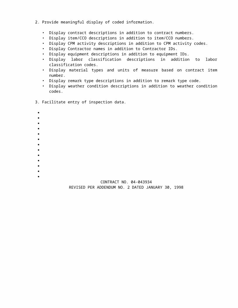
2-1.08 ESCROW OF BID DOCUMENTATIONBid documentation shall consist of all documentary and calculated information generated by the Contractor in
preparation of the bid. The bid documentation shall conform to the requirements in these special provisions, and shall be submitted to the Department and held in escrow for the duration of the contract.
In the resolution of disputes involving the project, the escrowed bid documents will be the only documents accepted from the Contractor regarding preparation of the bid.
In signing the proposal, the bidder certifies that the material submitted for escrow constitutes all the documentary information used in preparation of the bid and that he has personally examined the contents of the container and that they are complete.
The bidder shall include with the proposal, the identification of the bidder's representative authorized to present the bid documentation and the persons responsible for preparing the bidder's estimate.
Nothing in the bid documentation shall be construed to change or modify the terms or conditions of the contract.Escrowed bid documentation will not be used for pre-award evaluation of the Contractor's anticipated methods of
construction, nor to assess the Contractor's qualifications for performing the work.Bid documentation shall clearly itemize the Contractor's estimated costs of performing the work. The
documentation submitted shall be complete and so detailed as to allow for an in-depth analysis of the Contractor's estimate.
The bid documentation shall include, but not be limited to: quantity takeoffs; rate schedules for the direct costs and the time- and nontime-related indirect costs for labor (by craft), plant and equipment ownership and operation, permanent and expendable materials, insurance and subcontracted work; estimated construction schedules, including sequence and duration and development of production rates; quotations from subcontractors and suppliers; estimates of field and home office overhead; contingency and margin for each contract item of work; and other reports, calculations and information used by the bidder to arrive at the estimate submitted with the proposal.
The Contractor shall also submit bid documentation for each subcontractor whose total subcontract exceeds $250,000. Subcontractor bid documentation shall be enclosed with the Contractor's submittal. The examination of subcontractors' bid documentation will be accomplished in the same manner as for the Contractor's bid documentation. If a subcontractor is replaced, bid documentation for the new subcontractor shall be submitted for review and escrow before authorization for the substitution will be granted. Upon request of a subcontractor, the bid documentation from that subcontractor shall be reviewed only by the subcontractor and the Department.
If the bidder is a joint venture, the bid documentation shall include the joint venture agreement, the joint venture estimate comparison and final reconciliation of the joint venture estimate.
Copies of the proposals submitted by the first, second and third low bidders will be provided to the respective bidders for inclusion in the bid documentation to be escrowed.
The first, second, and third apparent low bidders shall present the bid documentation for escrow at the District 04 Office, 111 Grand Avenue, Room 12-816, Oakland, CA, on the first Monday, at 10:00 a.m., following the time indicated in the "Notice to Contractors" for the opening of bids.
Bid documentation shall be submitted in a sealed container, clearly marked with the bidder's name, date of submittal, project contract number and the words, "Bid Documentation for Escrow."
Failure to submit the actual and complete bid documentation as specified herein within the time specified shall be cause for rejection of the proposal.
Upon submittal, the bid documentation of the apparent low bidder will be examined and inventoried by the duly designated representatives of the Contractor and the Department to ensure that the bid documentation is authentic, legible, and in accordance with the terms of this section "Escrow of Bid Documentation." The examination will not include review of, nor will it constitute approval of, proposed construction methods, estimating assumptions or interpretation of the contract. The examination will not alter any conditions or terms of the contract. The acceptance or rejection by the Department that the submitted bid documents are in compliance with this section "Escrow of Bid Documentation" shall be completed within 48 hours of the time the bid documentation is submitted by the Contractor.
At the completion of the examination, the bid documents will be sealed and jointly deposited at an agreed commercial bank.
Bid documentation submitted by the second and third apparent low bidders will be jointly deposited at agreed commercial banks. If the apparent low bid is withdrawn or rejected, the bid documentation of the second low bidder will be examined and inventoried in the manner specified above, then sealed and deposited again in escrow. If the second low bid is withdrawn or rejected, the bid documentation of the third low bidder will be examined and inventoried in the manner specified above, then sealed and deposited again in escrow. Upon execution and final approval of the contract or rejection of all bids, the bid documentation will be returned to any remaining unsuccessful bidders.
The escrowed bid documentation may be examined by the designated representatives of both the Department and the Contractor, at any time deemed necessary by either the Department or the Contractor to assist in the negotiation of price adjustments and change orders, or in the settlement of claims or disputes.
CONTRACT NO. 04-043934ADDED PER ADDENDUM NO. 2 DATED JANUARY 30, 1998

If requested by a Disputes Review Board, the escrowed bid documentation may be utilized to assist the Board in its recommendations.
The bid documentation submitted by the Contractor will be held in escrow until the contract has been completed, the ultimate resolution of all disputes and claims has been achieved and receipt of final payment has been accepted by the Contractor. The escrowed bid documentation will then be released from escrow to the Contractor.
The bid documentation submitted by the bidder is, and shall remain, the property of the bidder, and is subject to only joint review by the Department and the bidder. The Department stipulates and expressly acknowledges that the submitted bid documentation constitutes trade secrets and will not be deemed public records. This acknowledgment is based on the Department's express understanding that the information contained in the bid documentation is not known outside the bidder's business, is known only to a limited extent and only by a limited number of employees of the bidder, is safeguarded while in the bidder's possession, is extremely valuable to the bidder and could be extremely valuable to the bidder's competitors by virtue of it reflecting the bidder's contemplated techniques of construction. The Department acknowledges that the bid documentation includes a compilation of information used in the bidder's business, intended to give the bidder an opportunity to obtain an advantage over competitors who do not know of or use the contents of the documentation. The Department agrees to safeguard the bid documentation, and all information contained therein, against disclosure, including disclosure of subcontractor bid documentation to the Contractor and other subcontractors to the fullest extent permitted by law. However, in the event of arbitration or litigation, the bid documentation shall be subject to discovery, and the Department assumes no responsibility for safeguarding the bid documentation unless the Contractor has obtained an appropriate protective order issued by the arbitrator or the court.
Full compensation for preparing the bid documentation, presenting it for escrow and reviewing it for escrow and upon request of the Engineer shall be considered as included in the contract prices paid for the various items of work, and no additional compensation will be allowed therefor.
The direct cost of depositing the bid documentation in escrow at the agreed commercial bank will be paid by the State.
CONTRACT NO. 04-043934ADDED PER ADDENDUM NO. 2 DATED JANUARY 30, 1998


5-1.44 TIDAL CONDITIONS AND ELEVATION DATUMAttention is directed to Section 2-1.03, "Examination of Plans, Specifications, Contract, and Site of Work."Tidal conditions may present significant problems in constructing the work as depicted in the contract plans.
Tidal fluctuations may be severe and different from those shown in published tidal and current data due to differences in datum, winter runoff and other causes. Strong currents exist over portions of the project site. Limited time periods of slack water may restrict diving and other underwater activities.
The Contractor is responsible for being knowledgeable of such tidal difficulties, and no payment will be made by the State for any costs incurred by the Contractor in connection with the variations in actual tidal or current conditions during the course of this contract. Any reference to Mean Higher High and Mean Lower Low tides shall be understood to be an estimate used for permit purposes, actual mean tide data shall be determined by the Contractor.
All vertical control data are based on the National Geodetic Vertical Datum of 1929.
CONTRACT NO. 04-043934ADDED PER ADDENDUM NO. 2 DATED JANUARY 30, 1998

5-1.45 STATE OWNED CATWALKS AND SCAFFOLDSOn the Carquinez Bridge, there are State owned catwalks that will be available for Contractor’s use when not
being used by the bridge paint and maintenance forces. Arrangements for their use shall be made to the Engineer and maintenance forces 7 calendar days in advance.
Attention is directed to “Cooperation” elsewhere in these special provisions.
State maintenance personnel will instruct Contractor’s personnel on how to use the catwalks. Thereafter, operation of the catwalks for contract work will be the responsibility of the Contractor.
The catwalks were designed to support maintenance personnel using small tools and equipment and painting equipment only. The Contractor shall not impose any greater loads upon the catwalk than intended by the catwalk design.
CONTRACT NO. 04-043934ADDED PER ADDENDUM NO. 2 DATED JANUARY 30, 1998

5-1.46 LOADS ON STRUCTURESAttention is directed to “Existing Highway Facilities” elsewhere in these special provisions.No lines for anchoring equipment shall be attached to the existing structure and pier fenders except with prior
written approval the Engineer of the proposed methods of securing barges and other equipment. The Contractor shall submit working drawings for proposed method of securing barges and other equipment to the Engineer for his review and approval. Working drawings shall be approved by the Engineer before any work involving such drawings is performed. Such approval, if granted, shall in no way relieve the Contractor of his responsibility for preservation of property under Section 7-1.11, “Preservation of Property,” of the Standard Specifications.
CONTRACT NO. 04-043934ADDED PER ADDENDUM NO. 2 DATED JANUARY 30, 1998

ENGINEER'S ESTIMATE04-043934
Item Item Code
Item Unit of Measure
Estimated Quantity
Unit Price Item Total
61(S)
159104 RAISE BRIDGE, LOCATION C LS LUMP SUM LUMP SUM
62 160101 CLEARING AND GRUBBING LS LUMP SUM LUMP SUM
63 170101 DEVELOP WATER SUPPLY LS LUMP SUM LUMP SUM
64 190101 ROADWAY EXCAVATION CY 5,850
65 011318 ROADWAY EXCAVATION (HAZARDOUS MATERIAL)
CY 5,280
66 011319 DRAINAGE EXCAVATION (HAZARDOUS)
CY 2,360
67(S)
011320 SAINTARY SEWER EXCAVATION (HAZARDOUS)
CY 690
68(F)
192003 STRUCTURE EXCAVATION (BRIDGE)
CY 832
69(S)
011916 WATER CONTROL LS LUMP SUM LUMP SUM
70 047079 STRUCTURE EXCAVATION (CONTAMINATED)
CY 1,598
71(F)
192021 STRUCTURE EXCAVATION (TYPE DH)
CY 3,035
72(F)
192023 STRUCTURE EXCAVATION (TYPE H)
CY 2,145
73(S-F)
011321 STRUCTURE EXCAVATION (RETAINING WALL, TYPE H)
CY 370
74(F)
193003 STRUCTURE BACKFILL (BRIDGE) CY 2,141
75(S-F)
193013 STRUCTURE BACKFILL (RETAINING WALL)
CY 280
76 011322 DRAINAGE BACKFILL(CLASS 3 AB) CY 860
77 011323 DRAINAGE BACKFILL (IMPORTED BORROW)
CY 940
78(S)
011324 SANITARY SEWER BACKFILL (CLASS 3 AB)
CY 140
79(S)
011325 SANITARY SEWER BACKFILL (IMPORTED BORROW)
CY 250
80 193114 SAND BACKFILL CY 47
6REVISED PER ADDENDUM NO. 2 DATED JANUARY 30, 1998
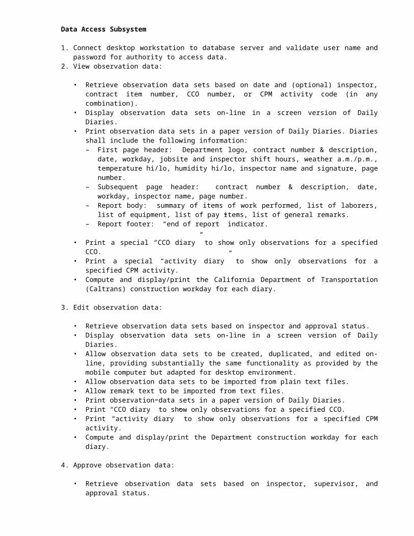
ENGINEER'S ESTIMATE04-043934
Item Item Code
Item Unit of Measure
Estimated Quantity
Unit Price Item Total
81 198001 IMPORTED BORROW TON 2,780
82(S)
203003 STRAW (EROSION CONTROL) TON 8
83(S)
203014 FIBER (EROSION CONTROL) TON 2
84(S)
203040 SEED (EROSION CONTROL) LB 170
85(S)
203056 COMMERCIAL FERTILIZER (EROSION CONTROL)
TON 1
86(S)
203061 STABILIZING EMULSION (EROSION CONTROL)
LB 460
87 260301 CLASS 3 AGGREGATE BASE CY 3,060
88 390155 ASPHALT CONCRETE (TYPE A) TON 9,969
89 394040 PLACE ASPHALT CONCRETE DIKE (TYPE A)
LF 100
90 394042 PLACE ASPHALT CONCRETE DIKE (TYPE B)
LF 380
91 394044 PLACE ASPHALT CONCRETE DIKE (TYPE C)
LF 130
92(S)
394048 PLACE ASPHALT CONCRETE DIKE (TYPE E)
LF 2,790
93(S)
490604 30" CAST-IN-DRILLED-HOLE CONCRETE PILING
LF 17,750
94(S)
046821 48" CIDH PILING (W/PERMANENT CASING)
LF 1,440
95(S)
500010 PRESTRESSING LS LUMP SUM LUMP SUM
96(S)
046823 PRESTRESSING HIGH STRENGTH ROD (LOCATION A)
LS LUMP SUM LUMP SUM
97(S)
046824 PRESTRESSING HIGH STRENGTH ROD (LOCATION B)
LS LUMP SUM LUMP SUM
98(S)
046825 PRESTRESSING HIGH STRENGTH ROD (LOCATION C)
LS LUMP SUM LUMP SUM
99(S)
046826 PRESTRESSING CONCRETE EXTERNAL TENDON (LOCATION A)
LS LUMP SUM LUMP SUM
100(S)
046827 PRESTRESSING CONCRETE EXTERNAL TENDON (LOCATION B)
LS LUMP SUM LUMP SUM
7REVISED PER ADDENDUM NO. 2 DATED JANUARY 30, 1998

ENGINEER'S ESTIMATE04-043934
Item Item Code
Item Unit of Measure
Estimated Quantity
Unit Price Item Total
141 568007 INSTALL SIGN OVERLAY SQFT 59
142(S)
046841 CLEAN AND PAINT STRUCTURAL STEEL (LOCATION A)
LS LUMP SUM LUMP SUM
143(S)
046842 CLEAN AND PAINT STRUCTURAL STEEL (LOCATION B)
LS LUMP SUM LUMP SUM
144(S)
046843 CLEAN AND PAINT STRUCTURAL STEEL (LOCATION C)
LS LUMP SUM LUMP SUM
145(S-F)
590135 SPOT BLAST CLEAN AND PAINT UNDERCOAT
SQFT 26,120
146(S)
597600 PREPARE AND PAINT CONCRETE SQFT 960
147 650010 12" REINFORCED CONCRETE PIPE LF 490
148 650014 18" REINFORCED CONCRETE PIPE LF 990
149 650026 36" REINFORCED CONCRETE PIPE LF 240
150 650034 48" REINFORCED CONCRETE PIPE LF 180
151 703509 6" WELDED STEEL PIPE (.134" THICK)
LF 70
152 705204 18" CONCRETE FLARED END SECTION
EA 1
153 707117 36" PRECAST CONCRETE PIPE INLET
LF 19
154(S)
011917 ABANDON SEWER EA 6
155(S)
011918 ADJUST MANHOLE TO GRADE EA 3
156(S)
011919 REMOVE SEWER MANHOLE EA 1
157(S)
011920 4" CLAY SEWER PIPE LF 40
158(S)
011327 4" CLAY SEWER PIPE IN DIP CASING
LF 5
159(S)
714034 8" CLAY SEWER PIPE LF 150
160(S)
714038 18" CLAY SEWER PIPE LF 150
10REVISED PER ADDENDUM NO. 2 DATED JANUARY 30, 1998

ENGINEER'S ESTIMATE04-043934
Item Item Code
Item Unit of Measure
Estimated Quantity
Unit Price Item Total
201(S)
011332 SIGNAL AND LIGHTING (STAGE CONSTRUCTION- LOCATION 2)
LS LUMP SUM LUMP SUM
202(S)
861504 MODIFY LIGHTING AND SIGN ILLUMINATION
LS LUMP SUM LUMP SUM
203(S)
047001 SEISMIC MONITORING SYSTEM LS LUMP SUM LUMP SUM
204 046846 INSTALL SEISMIC MONITORING CASING (DOWNHOLE)
LF 225
205 011914 TIME RELATED OVERHEAD WDAY 780
206 BLANK
207 999990 MOBILIZATION LS LUMP SUM LUMP SUM
TOTAL BID:
13REVISED PER ADDENDUM NO. 2 DATED JANUARY 30, 1998

INFORMATIONAL HANDOUT04-CC,Sol-80-12.8/14.1,0.0/0.6
04-043934
List of material suppliers for the “SHOCK TRANSMISSION DEVICES.”
The following STD manufacturer’s may be qualified to manufacture STD’s of the size and stroke required for the Carquinez Bridge Retrofit. The Contractor’s attention is directed to the required "Qualification Data Package" for the STD manufacturer which must be submitted as a part of the bid.
Dynamic Isolation Systems, Inc. for Jarret of France3470 Mt. Diablo Boulevard, Suite A200Lafayette, California 94549Phone (510)283-1166Fax (510)283-4307Contact: Ron Mayes
Enidine Incorporated212 Technology Drive, Suite MIrvine, CA 92718Phone (714)727-9112Fax (714)727-9107Contact: Mike Siino
Taylor Devices Inc.90 Taylor DrivePO Box 748North Tonawanda, New York 14120-0748Phone: (716)694-0800Fax (716)695-6015Contact: Craig Winters/Bob Schneider
Colebrand Inc.1101 Connecticut Ave NW, Suite 1200Washington DC 20036Phone: (202)828-2481Fax: (202)828-2440Contact: Carol Rowland
FIP-Energy Absorption Systems, LLC1633 Old Bayshore Highway, Suite 250Burlingame, CA 94010Phone (415)652-7934Fax (415)652-7924Contact: Byron F. West, Jr.
Lisega375 Lisega BoulevardNewport, Tennessee 37821Phone: (423)625-2000Fax: (423)625-9009Contact: Ray Miller

STATE OF CALIFORNIA-BUSINESS, TRANSPORTATION AND HOUSING AGENCY PETE WILSON, Governor DEPARTMENT OF TRANSPORTATIONESC/OE MS #43P.O. Box 942874SACRAMENTO, CA 94274-0001
TDD (916) 654-4014
Use Word 6.0c or later to
view Mac intosh pi cture .
February 6, 1998
04-CC,Sol-80-12.8/14.1,0.0/0.604-043934
Addendum No. 3
Dear Contractor:
This addendum is being issued to the contract for construction on State highway in CONTRA COSTA AND SOLANO COUNTIES AT CROCKETT AND IN VALLEJO FROM CUMMINGS SKYWAY OVERCROSSING TO CARQUINEZ BRIDGE TOLL PLAZA..
Submit bids for this work with the understanding and full consideration of this addendum. The revisions declared in this addendum are an essential part of the contract.
Bids for this work will be opened on April 29, 1998, instead of the original date of February 18, 1998.
This addendum is being issued to set a new bid opening date as shown herein and revise the Project Plans, the Notice to Contractors and Special Provisions, and the Engineer's Estimate.
Project Plan Sheets 117, 118, 119, 120, 121, 122, 123 are revised. Half-sized copies of the revised sheets are attached for substitution for the like numbered sheets.
Project Plan Sheets 123A is added. A half-sized copy of the added sheet is attached for addition to the project plans.
In the Notice To Contractors And Special Provisions, in the "Pre-Award Meeting Special Notice" and the first paragraph of Section 3, and in the Proposal And Contract in the "Pre-Award Meeting Special Notice", the pre-award qualifications review meeting date is revised from February 20, 1998 to May 1, 1998.
In the Special Provisions, Section 2-1.08, "Escrow Of Bid Documentation" the twelfth paragraph is revised as follows:
"The first, second, and third apparent low bidders shall present the bid documentation for escrow at the District 04 Office, 111 Grand Avenue, Room 12-816, Oakland, CA, on the first Monday, at 1:00 p.m., following the time indicated in the "Notice to Contractors" for the opening of bids."
In the Special Provisions, Section 4, "Beginning Of Work, Time Of Completion And Liquidated Damages" the fourth paragraph is revised as follows:
"The Contractor shall pay to the State of California the sum of $2,900 per day, for each and every calendar day's delay in finishing the work in excess of the number of working days prescribed above."
In the Special Provisions, Section 5-1.11, "Removal of Asbestos and Hazardous Substances", the sixth paragraph is deleted.
In the Special Provisions, Section 5-1.21, "Hazardous Material, General" is revised to "Contaminated And Hazardous Material, General" as attached.
In the Special Provisions, Section 5-1.28, "Relations With Bay Conservation And Development Commission" is revised as attached.

Addendum No. 3 04-CC,Sol-80-12.8/14.1,0.0/0.6Page 2 04-043934February 6, 1998
In the Special Provisions, Section 5-1.31, "Utilities", the fifth paragraph is revised as follows:
"Attention is directed to Section 7-1.11, “Preservation of Property,” of the Standard Specifications."
In the Special Provisions, Section 10-1.01, "Order Of Work" is revised as attached.
In the Special Provisions, Section 10-1.015, "Photography" is added as attached.
In the Special Provisions, Section 10-1.04, "Non-Storm Water Discharges" is revised as attached.
In the Special Provisions, Section 10-1.05, "Temporary Metal Beam Guard Railing" the last sentence of the tenth paragraph is deleted.
In the Special Provisions, Section 10-1.13, "Obstructions" is revised as attached.
In the Special Provisions, Section 10-1.17, "Maintaining Traffic", Table A, under "Traffic Maintenance Provision For Vehicular Traffic" for "Wanda Street (Ceres Street To Port Street)" the last sentence is revised as follows:
"Must be finished by October 15, 1998."
In the Special Provisions, Section 10-1.27, "Moveable Concrete Barrier" the fifteenth paragraph is revised as follows:
"The price quoted by the manufacturer for the above transfer, transport machine, and to provide all parts and service materials will be $216,000.00 per unit based on two required units and upon a two (2) year lease, F.O.B. 180 River Road, Rio Vista, California 94571."
In the Special Provisions, Section 10-1.28, "Existing Highway Facilities" the following paragraph is added after the fifth paragraph:
"The allowable concentrated loads “P” that may be placed upon the existing travelers rails are:At any rail support: P= 18,400 lbs. (total from all loads on the rails)At any point on the rails between support brackets: P= 6,000 lbs. (total for one 15’-6” span
between support brackets)".
In the Special Provisions, Section 10-1.28D, "Remove Guard Railing And Double Metal Beam Barrier" the following is added after the first paragraph:
"Holes and pits caused by the removal of guard railing and double metal beam barrier shall be backfilled with slurry cement backfill.
Full compensation for slurry cement backfill of holes and pits caused by removal of guard railing and double metal beam barrier shall be considered as included in the contract price paid per linear foot for remove metal beam guard railing and remove double metal beam barrier and no additional compensation will be allowed therefor."
In the Special Provisions, Section 10-1.28U, "Bridge Utility And Maintenance Equipment Work" the last sentence of the first paragraph is deleted.
In the Special Provisions, Section 10-1.31, "Earthwork" the following paragraph is added after the eighteenth paragraph:
"Care shall be taken during installation of the cofferdam for the work at Pier 5 to prevent disturbing the nearby utilities, including the 20-inch steel waterline. The design of the cofferdam shall include a narrative with supporting calculations explaining how the cofferdam will be installed without disturbing the utilities. It shall include a contingency plan describing steps the Contractor will take in the event one or more of the utilities is damaged as a result of the Contractor’s

operations. A clear distance of two feet shall be maintained between the cofferdam and the electrical line."

Addendum No. 3 04-CC,Sol-80-12.8/14.1,0.0/0.6Page 3 04-043934February 6, 1998
In the Special Provisions, Section 10-1.31B, "Drainage Excavation And Backfill" the second paragraph is revised as follows:
"Drainage excavation and backfill will be measured and paid for as drainage excavation (hazardous), drainage excavation (contaminated), drainage backfill (Class 3 AB) and drainage backfill (imported borrow) in the same manner as structure excavation and backfill."
In the Special Provisions, Section 10-1.31C, "Hazardous Material Excavation" is revised to "Contaminated And Hazardous Material Excavation" as attached.
In the Special Provisions, Section 10-1.31E, "Dredging" the first paragraph is revised as follows:
"All excavation involved with the removal and disposal of the bay sediment material from within the steel shells at cast-in-steel-shell concrete piling and permanent steel casings at cast-in-drilled-hole concrete piling and from inside (temporary) cofferdam at Pier 5 of the "A4E" Line Mainspan structure shall be considered dredging under the terms of the various permits obtained by the State."
In the Special Provisions, Section 10-1.31F, "Ductbank Excavation" is added as attached.
In the Special Provisions, Section 10-5.01, "Sewers" the sixth and seventh paragraphs of subsection "Measurement And Payment" are revised as follows:
"Structure excavation and structure backfill for sewer manholes, and the different sizes and types of sewer pipes will be measured and paid for separately as sanitary sewer excavation (hazardous), sanitary sewer excavation (contaminated) and sanitary sewer backfill (Class 3 AB) in paved areas and sanitary sewer backfill (imported borrow) in unpaved areas.
Full compensation for sanitary sewer excavation and backfill shall be considered as included in the contract prices paid per cubic yard for sanitary sewer excavation (hazardous), sanitary sewer excavation (contaminated), sanitary sewer backfill (imported borrow), and sanitary sewer backfill (class 3 aggregate base), and no additional compensation will be allowed therefor."
In the "Copy of Engineer's Estimate" in the NOTICE TO CONTRACTORS and the "Engineer's Estimate" in the PROPOSAL, Items 24, 32, 39, 64, 65, 66, 67, 76, 77, 80, 81, 87, 88, 105, 147, 149, 164, 165, 169, 170, 175, 183, 189, 206, 207 are revised and Items 208, 209, 210, 211 and 212 are added and Item 185 is deleted as attached.
To Proposal and Contract book holders:
REPLACE THE ENTIRE ENGINEER'S ESTIMATE IN THE PROPOSAL WITH THE ATTACHED REVISED ENGINEER'S ESTIMATE. THE REVISED ENGINEER'S ESTIMATE IS TO BE USED IN THE BID SUBMITTAL AND INSERTED IN THE PROPOSAL.
PROVIDE A COPY OF INFORMATIONAL HANDOUT
INDICATE RECEIPT OF THIS ADDENDUM BY FILLING IN THE NUMBER OF THIS ADDENDUM IN THE SPACE PROVIDED ON THE SIGNATURE PAGE OF THE PROPOSAL.
Submit bids in the Proposal and Contract book you now possess. Holders who have already mailed their book will be contacted to arrange for the return of their book.
Inform subcontractors and suppliers as necessary.

Addendum No. 3 04-CC,Sol-80-12.8/14.1,0.0/0.6Page 4 04-043934February 6, 1998
This office is sending this addendum by UPS overnight mail to Proposal and Contract book holders to ensure that each receives it.
If you are not a Proposal and Contract book holder, but request a book to bid on this project, you must comply with the requirements of this letter before submitting your bid.
Sincerely,
ORIGINAL SIGNED BY
NICK YAMBAO, ChiefPlans, Specifications &Estimates BranchOffice of Office Engineer
Attachments

5-1.21 CONTAMINATED AND HAZARDOUS MATERIAL, GENERALAttention is directed to "Earthwork" of these special provisions regarding the removal and disposal of
contaminated and hazardous material. Contaminated and hazardous material have been discovered through testing within the project limits. Site
investigation reports are available for inspection at the Department of Transportation, Toll Bridge Program Duty Senior’s Office, 111 Grand Avenue, Oakland, California, (510) 286-5549. Requests to review the reports must be made with the duty senior at least 24 hours in advance. The levels of material designated as hazardous are not regulated under the Resource Conservation and Recovery Act (RCRA). The levels of hydrocarbon contamination are considered to be designated waste as defined by State of California regulations.
Hazardous materials shall be transferred directly from the excavation to a registered transport vehicle, a storage container approved for transport of hazardous waste by the United States Department of Transportation, or a stockpile location approved by the Engineer. Contaminated materials shall be transferred directly from the excavation to a transport vehicle, a storage container, or a stockpile location approved by the Engineer. Stockpile locations that contain shall be maintained in accordance with the following requirements:
The material shall not contain free liquids that separate readily from the material. The presence or absence of free liquids shall be demonstrated by United States Environmental Protection Agency Method 9095 as modified by Section 66264.314 of Title 22 of the California Code of Regulations (CCR). Fluids removed from the stockpile area shall be contained and analyzed for proper identification of constituents prior to both treatment and disposal. Removal, disposal, treatment, and analysis of the fluids shall be performed at the Contractor’s expense.
The material shall be stored on undamaged 60-mil high density polyethylene or an equivalent impermeable barrier unless the stockpiling location is on a paved surface. If the location is on a paved surface the thickness of the barrier can be reduced to 20-mil high density polyethylene or its equivalent. The dimensions of the barrier shall exceed the dimensions of the stockpile at all times. Any seams in the barrier shall be sealed to prevent leakage.
At the end of each day the material shall be covered with undamaged 12-mil polyethylene or an equivalent impermeable barrier to prevent windblown dispersion and precipitation run-off and run-on. When more than one sheet is required to cover the material, the sheets shall be overlapped a minimum of 1.5 feet in a manner that prevents water from flowing onto the material. The cover shall be secured in a manner that keeps it in place at all times. Driven anchors shall not be used except at the perimeter of the stockpile. The cover shall be inspected at the end of each work day and its integrity maintained in accordance with the requirements of these special provisions.
Stockpile requirements apply to all temporary storage of hazardous material outside of an excavation or a transport container including, but not limited to, staging of excavated material next to the excavation prior to pick up by loading equipment, accumulating material for full transport loads, and awaiting test results required by a disposal facility. The removal of stockpiles shall begin within 30 days of accumulating 100 kg (220 lbs.) of hazardous material. After final removal has occurred the Contractor shall be responsible for any cleanup deemed necessary by the Engineer.
No stockpiling of contaminated material or hazardous material will be allowed within the C&H property.All contaminated material and hazardous material on exteriors of transport vehicles shall be removed and placed
either into the current transport vehicle, a designated stockpile of similar material, or the excavation of origin prior to the vehicle leaving the exclusion zone. No contaminated material or hazardous material shall be deposited on public roads. The Contractor shall indemnify the State from any costs due to spillage during the transport of the contaminated or hazardous material to the disposal facility.
The Contractor shall monitor the air quality continuously during excavation operations at all locations containing hazardous material.
Disposal of additional material resulting from the Contractor’s option to slope the excavations in lieu of shoring at locations where this is possible or any excavation operations outside structure excavation pay limits will be at the Contractor’s expense. This resultant material shall be treated as either contaminated material or hazardous material as indicated within the tables presented within "Contaminated and Hazardous Material Excavation" of these special provisions.
APPLICABLE RULES AND REGULATIONS.--Excavation, transport and disposal of contaminated material and hazardous material shall be in accordance with the rules and regulations of the following agencies:
United States Department of Transportation (USDOT)United States Environmental Protection Agency (USEPA)California Environmental Protection Agency (CAL-EPA)
1. Department of Toxic Substance Control (DTSC) 2. Integrated Waste Management Board 3. Regional Water Quality Control Board, Region 2 (RWQCB) 4. State Air Resources Board
Bay Area Air Quality Management District (BAAQMD)

California Division of Occupational Safety and Health Administration (CAL-OSHA)
CONTRACT NO. 04-043934REVISED PER ADDENDUM NO. 3 DATED FEBRUARY 6, 1998

PERMITS AND LICENSES.--The Contractor shall procure all permits and licenses, pay all charges and fees, and give all notices necessary and incident to the due and lawful prosecution of the work, including registration for transporting vehicles carrying the contaminated material and the hazardous material. The California Environmental Quality Act (CEQA)of 1970 (Chapter 1433, Stats. 1970), as amended may be applicable to permits, licenses and authorizations which the Contractor shall obtain from all agencies in connection with performing the work of the contract. The Contractor shall comply with the provisions of said statutes in obtaining such permits, licenses and other authorizations.
The Engineer will obtain the Environmental Protection Agency Generator Identification No. and Board of Equalization Identification Number as the State is the Generator.
HEALTH, SAFETY AND WORK PLAN.--The Contractor shall prepare a detailed Health, Safety and Work Plan for all site personnel in accordance with the DTSC and CAL-OSHA regulations. The Health, Safety and Work Plan shall include a plot plan indicating the exclusion zones, contaminant reduction (decontamination zones) and support zones in accordance with California Code of Regulations (CCR), Title 8, an air monitoring plan, site clean up procedures, and physical barrier; and shall be submitted at least 15 working days prior to beginning any excavation for review and acceptance by the Engineer. Prior to submittal, the Contractor shall have the Health, Safety and Work Plan approved by a Civil Engineer, registered in the State of California and by an Industrial Hygienist certified by the American Board of Industrial Hygiene.
SAFETY.--Prior to performing any excavation work at the locations containing material classified as hazardous, all personnel, including State Personnel, shall complete a safety training program which meets 29 CFR 1910.120 and 8 CCR 5192 covering the potential hazards as identified. The training shall be provided by the Contractor. The Contractor shall provide a certification of completion of the Safety Training Program to all personnel. Any personal protective equipment required by the Contractor’s Health, Safety and Work Plan for personnel working within the exclusion zone will be supplied to State personnel by the Contractor. The number of State personnel requiring the above mentioned safety training program and personal protective equipment will be 12.
The decontamination area shall be located outside of the exclusion zone. Water from decontamination procedures shall be collected and disposed of at an appropriate disposal site by the Contractor. Non-reusable protective equipment, once used by any personnel, including State personnel, shall be collected and disposed of at an appropriate disposal site by the Contractor. Temporary 6-foot chain link security fence shall be installed to surround and secure the exclusion zone.
SAMPLING AND ANALYSIS.--The Contractor shall test the material to be excavated at his own expense for any additional acceptance requirements put forth by the disposal facility. Sampling and analysis shall be performed using the sampling and analysis procedure required by the disposal facility.
The Contractor may perform additional tests on the material to be excavated at his option and expense for confirmation of the material classification as contaminated or hazardous. Sampling and analysis shall be the same or equivalent tests as those described in the site investigation reports. The Contractor shall submit for approval by the Engineer, his sampling and analysis procedure and the name and address of the laboratory to be used fifteen working days prior to beginning any sampling or analysis. The laboratory used shall be certified by the California Department of Health Services.
MEASUREMENT AND PAYMENT. -- Full compensation for conforming to the requirements of this section shall be considered as included in the prices paid for the various contract items of work affected by this section and no additional compensation will be allowed therefor.

CONTRACT NO. 04-043934REVISED PER ADDENDUM NO. 3 DATED FEBRUARY 6, 1998

5-1.28 RELATIONS WITH SAN FRANCISCO BAY CONSERVATION AND DEVELOPMENT COMMISSION
A San Francisco Bay Conservation and Development Commission Permit is applicable to this project.Attention is directed to Sections 7-1.01, “Laws To Be Observed,” and 7-1.11, “Preservation of Property,” of the
Standard Specifications.The Contractor shall comply with all requirements and conditions of the Bay Conservation and Development
Commission and the permit obtained for this project with regard to the manner in which he conducts his operations and all construction-related activities.
The Contractor’s attention is directed to the following conditions which are among those established by the Bay Area Conservation and Development Commission in the permit for this project:
1. Notification to the Engineer in writing at least 30 days prior to any dredging operations.2. Dredging report, refer to the Earthwork section (Dredging Operations Plan) of these special provisions.3. Results of any effluent water quality or other testing required by the San Francisco Bay Regional Quality
Control Board shall be submitted in writing to the Engineer for submission to the Commission’s office at the same time such testing is submitted to the Regional Board.
4. No pilings or other wood structures that have been pressure treated with creosote shall be used in any area subject to tidal action in the Bay or any certain waterway, in any salt pond, or any managed wetland within the Commission’s jurisdiction as part of the project.
5. Any sunken debris resulting from the construction effort shall be immediately marked with buoys and removed within 90 days. The Contractor shall survey the channel following completion of all construction and certify to the Coast Guard that the waterway has been cleared to the natural bottom.
6. The contractor will be strictly prohibited from using solid fill in the bay for access except as provided for in sub-paragraphs 7 and 8 below.
7. The Contractor may install up to a maximum of 22,200 square feet of temporary fill to provide construction access consisting of pile-supported fill for working platforms and solid fill for pilings as defined in the materials information handout, "BCDC Extent of Jurisdiction and Definition of Fill."
8. The area of temporary, pile-supported fill for working platforms and solid fill for pilings, will be calculated by adding together the surface area of the platform (in SQFT) to be constructed and the cross-sectional area of the pilings (in SQFT).
9. Temporary fill shall be removed between December 1 and March 31 prior to overall project completion.
A Copy of Permit may be obtained at the Department of Transportation, Plans and Bid Documents, Room 0200, Transportation Building 1120 N Street, P.O. Box 942874, Sacramento, CA 94274-0001, Telephone No. (916) 654-4490, and are available for inspection at the Department of Transportation, Toll Bridge Seismic Retrofit Program Duty Senior’s Desk at 111 Grand Avenue, Oakland, CA.
Any modifications to the permit which are proposed by the Contractor shall be submitted in writing to the Engineer for transmittal to the Bay Conservation and Development Commission for their consideration.
When the Contractor is notified by the Engineer that a modification to the permit is under consideration, no work will be allowed on the proposed modification until the Department takes action on the proposed modification.
Any modifications to any agreement between the Department of Transportation and the Bay Conservation and Development Commission shall be fully binding on the Contractor.
The provisions of this section shall be made a part of every subcontract executed pursuant to this contract.Full compensation for conforming with the requirements of the Permit section shall be considered as included in
the contract prices paid for the various items of work involved and no additional compensation will be allowed therefor.
Contract No. 04-043934REVISED PER ADDENDUM NO. 3 DATED FEBRUARY 6, 1998


10-1.01 ORDER OF WORKOrder of work shall conform to the provisions in Section 5-1.05, "Order of Work," of the Standard Specifications
and these special provisions.General.--Suggested sequences of construction are shown on the plans. These sequences are shown for
information only. They may not show all work items or limits of work required and shall not be construed to be a project requirement. The Contractor shall submit and be responsible for developing a workable sequence of construction for this project.
A first order of work shall be installing and surveying benchmarks to be reset. Benchmarks shall be reset prior to doing any pile installation on the pier where the benchmarks are located.
Attention is directed to the provisions in Section "Steel Structures", of these special provisions where the Contractor shall produce the in-field survey of the as-built dimensions and details of the steel structures which require modification. This survey and the working drawings shall be a first order of work.
Attention is directed to Section "Temporary Supports" of these special provisions. At the locations shown on the plans, temporary supports and temporary bracing shall be in place prior to beginning removal of the existing bearings. Attention is directed to "Railroad Relations and Insurance," of these special provisions for additional requirements for construction over railroads.
All work in water at Pier 5 shall be limited to the period between December 1 and March 31 to minimize impacts on the Delta smelt, a federally listed threatened species.
Construction on Bents "A10E" through "A13E" on the C&H Sugar Company property shall be started and completed one at a time.
A first order of work shall be to place the order for the traffic signal equipment. The Contractor shall furnish the Engineer with a statement from the vendor that the order for said equipment has been received and accepted by said vendor.
The uppermost layer of new pavement shall not be placed until all underlying conduits and loop detectors have been installed.
Prior to commencement of the traffic signal functional test at any location, all items of work related to signal control shall be completed and roadside signs and all pavement delineation and pavement markings shall be in place at that location.
Attention is directed to "Maintaining Traffic" and "Temporary Pavement Delineation" of these special provisions and to the stage construction sheets of the plans.
Attention is directed to "Cooperation" of these special provisions for requirements related to protection and relocation of the PG&E’s 26 inch diameter high pressure gas line and Pacific Bell’s fiber optic cable.
Attention is directed to "Environmentally Sensitive Areas" of these special provisions regarding installation of temporary high visibility boundary fence around environmentally sensitive areas before starting any work around these areas.
Before obliterating any pavement delineation that is to be replaced on the same alignment and location, as determined by the Engineer, such pavement delineation shall be referenced by the Contractor, with a sufficient number of control points to reestablish the alignment and location of the new pavement delineation. The references shall also include the limits or changes in striping pattern, including one- and two-way barrier lines, limit lines, crosswalks and other pavement markings. Full compensation for referencing pavement delineation shall be considered as included in the contract prices paid for new pavement delineation and no additional compensation will be allowed therefor.
At the end of each working day if a difference in excess of 0.15-foot exists between the elevation of the existing pavement and the elevation of any excavation within 8 feet of the traveled way, material shall be placed and compacted against the vertical cuts adjacent to the traveled way. During excavation operations, native material may be used for this purpose, however, once the placing of the structural section commences, structural material shall be used. The material shall be placed to the level of the elevation of the top of existing pavement and tapered at a slope of 4:1 or flatter to the bottom of the excavation. Full compensation for placing the material on a 4:1 slope, regardless of the number of times it is required, and subsequent removing or reshaping of the material to the lines and grades shown on the plans shall be considered as included in the contract price paid for the materials involved and no additional compensation will be allowed therefor. No payment will be made for material placed in excess of that required for the structural section.
At locations exposed to public traffic where guard railings or barriers are to be constructed, reconstructed, or removed and replaced, the Contractor shall schedule his operations so that at the end of each working day there shall be no post holes open nor shall there be any railing or barrier posts installed without the blocks and rail elements assembled and mounted thereon.
Temporary crash cushion modules and temporary railing (Type K) shall be in place at locations shown on the plans prior to starting any adjacent construction activities.
Approach Span “A4E” and On Ramp “D” Lines:
A first order of work shall be performing the pile load testing. Pile load testing shall proceed in the following order: load testing at Bent A12E, then load testing at Bent A9E and finally, load testing at Bent A8E.

Work at Abutment 2A shall be performed without interrupting the traffic on the Approach "A4E" Line, except as noted otherwise in these special provisions or directed by the Engineer.
Contract No. 04-043934REVISED PER ADDENDUM NO. 3 DATED FEBRUARY 6, 1998

A first order of work shall be to furnish preconstruction test panels for shotcrete. Shotcrete test panels shall be completed and approved by the Engineer prior to construction of production shotcrete. Shotcrete on the faces of the bent columns where the steel column casings are installed shall not begin until the unit of the column casing assembly has been completely inspected and accepted by the Engineer in writing.
The “A4E” Line Approach Spans shall be closed to all traffic during the removal of the bolts holding the Span 13E stringers to the floor beams until the new bolts holding the retrofit “T’s” and Span 13E stringers to the floor beams are installed.
A first order of work shall be completion of load test pile construction and testing. Pile load testing shall be completed prior to construction of production piles, with the exception of test pile reaction piles to be incorporated into the completed structure.
The Contractor shall allow local businesses to relocate parking from the vicinity of Bent 12 to the vicinity of Bent 11 before beginning retrofit construction at Bent 12. The Contractor shall allow local businesses to relocate parking from the vicinity of Bent 11 to the vicinity of Bent 12 before beginning retrofit construction at Bent 11.
A 26-inch-diameter gas line will be relocated by others from Span 13 and Bent 13 of Approach A4E to Pier 5 of the A4E Main Spans, and from the west side of the A4E Main Spans to the east side of the A4E Main Spans. Retrofit of Bent 13 and the hinge in Span 13 shall not be initiated until the gas line has been relocated.
The Contractor shall furnish and install pipe supports for the relocated high pressure gas line as specified in Section "Miscellaneous Metal (Bridge)" of these special provisions before the high pressure gas line relocation work (by others) begins. Attention is directed to Section 10-1.13, "Obstructions", for additional information on gas pipeline work.
Gas line relocation: The Contractor shall be responsible for coordinating the gas line relocation(by others) with the construction at Bent A13E of the Approach Span “A4E” Line
The Contractor shall complete concrete seismic upgrade work on Pier 5 before or concurrently with installing pipe supports on Pier 5.
A span shall not be left on temporary supports for a period longer than 40 working days. The Contractor’s attention is directed to the need to provide longitudinal restraint where work is to be done on the fixed end bearings of a span. Restraint shall be provided in accordance with “Temporary Supports” of these special provisions.
New or existing restrainers shall be in place on at least one end of each span at all times. All removal and replacement or restrainers shall be done symmetrically about the center line of the existing bridge.
The bottom edge of the existing bridge footings shall be removed to expose the existing footing reinforcing prior to drilling for the CIDH concrete piles. Pile locations may be adjusted up to 4 inches, as approved by the Engineer, to pass extensions of existing footing reinforcing through CIDH vertical reinforcing as shown on the drawings.
Main Span "A4E":
A first order of work shall be to initiate design, manufacture and testing of shock transmission devices.
Gas line relocation: The Contractor shall complete all work at the outside face of the east truss before the existing 26-inch-diameter high-pressure gas line is relocated(by others) from the west side of bridge to the east side of bridge, including all work at the bottom chord between panel points L29 to L30, L44 to L45, L71 to L72, and L86 to L87. The gas line shall be relocated (by others) before beginning work on outside face of west truss. Also see additional provisions for work on the lower chords. The Contractor shall be responsible for coordinating the gas line relocation(by others) with the construction at Pier 5.
Attention is directed to "Bridge Utility and Maintenance Equipment Work" elsewhere in these special provisions. The Contractor shall remove interferences on the east side of the bridge before the high-pressure gas line is relocated (by others). Interferences include bridge appurtenances such as maintenance ladders, maintenance platforms, seismic instrumentation, light beacon, and water drain near Abutment 1.
The Contractor shall complete concrete seismic upgrade work on Pier 5 before or concurrently with installing pipe supports on Pier 5.
Truss and Tower Member Connections: When gusset plates are to be removed from both sides of a joint, construction shall be limited to one side of the connection at a time, except as noted below or on the plans.
Top Lateral Cross-Bracing: At top lateral cross bracing, gusset plates are located on two faces of the panel, the top face and the bottom face. All retrofit of gusset plates within a panel shall be accomplished one face at a time, either all the top face gusset plates shall be retrofit first or all the lower face gusset plates shall be retrofit first. A panel shall be defined as the structure between two adjacent even-numbered panel points, inclusive of the transverse struts at the panel points.
Contract No. 04-043934REVISED PER ADDENDUM NO. 3 DATED FEBRUARY 6, 1998

Sway/Portal Braces: No work is permitted on connections of sway or portal braces within any span while any connections within the top lateral bracing of that span are partially or completely disassembled. For this requirement, the superstructure is considered to consist of two anchor spans, four cantilever spans, two suspended spans, and one tower span.
Shock Transmission Devices and Bottom Chord Replacement: The Contractor shall complete chord replacement and shock transmission device work at one end of a suspended span before beginning work at the opposite end of that suspended span. Work shall not occur on both east and west chords near a suspended span simultaneously.
Bottom Laterals: At least one cross brace, defined as a horizontal member extending from one chord through a floor beam to the other chord, shall have all top gussets or all bottom gussets completely bolted at all times. These members and gussets required to be in place may be existing construction, new construction, or a combination of new and existing construction.
Work on bottom chords between panel points L44 and L46 shall not coincide with work on bottom chord lateral bracing between panel points L44 and L46, and work on bottom chords between panel points L70 and L72 shall not coincide with work on bottom chord lateral bracing between panel points L70 and L72.
Truss Anchors/Sliding Bearing Devices: At Abutment 1 and at Pier 5, complete installation of new bearing device at one chord before removal of existing truss anchor at opposite chord. Work may proceed on truss anchors at Abutment 1 and Pier 5 concurrently.
Towers 2 and 4: Connect existing base plate to existing masonry plate before removing lateral or chevron brace connections. Install temporary vertical bracing before removing connections of lower tier (between elevations 18.0 and 59.0) chevron braces. At each tower, only one lower tier chevron brace may be disconnected at one time. Complete work on all lower tier chevrons, transverse horizontal struts at elevation 22.0, and horizontal cross bracing at elevation 22.0 before removing existing north-south horizontal struts at elevation 22.0 between tower legs.
At each tower, complete all work on lower tier chevrons, all tower base shear locks, and transfer girders before raising tower legs or otherwise modifying the base of the tower legs. Raise or lower only one tower leg at a time. Close the bridge to traffic while raising or lowering is in progress.
Tower 3: At each tower leg complete bolting of exterior hold-down girder to leg, longitudinal horizontal strut, and longitudinal chevron before disassembly of gusset plate connection at interior of tower leg.
Existing horizontal cross braces at elevation 22.0 and elevation 88.07 may be used to brace the tower during construction. Stage work to maintain at least one existing brace per elevation between panel points 56 and 58 and one existing brace per elevation between panel points 58 and 60.
Tower 3 Transverse Chevrons: At each transverse chevron braced frame install temporary vertical support before removing the connection of the lower tier (between elevation 18.0 and 56.2) chevron braces. Only one lower tier transverse chevron may be disconnected at a time.
Tower 3 connection to bottom chord, panel point L58: Work on the tower diagonal connections to the bottom chord at panel point L58 at one side of the structure shall be complete before disconnecting the tower diagonal to bottom chord connection at the opposite side of the structure. Work on the tower diagonal connections to bottom chords at panel point L58 shall not coincide with work on the bottom laterals between panel points L56 and L60.
Top of Pier No. 5: Prior to coring vertical holes in the top of Pier No. 5, core 3" diameter horizontal holes and pressure grout horizontal threaded bar anchor with anchorages.
All work on Wanda Street shall be completed by October 15, 1998 to facilitate work on the Carquinez Replacement Project.
Contract No. 04-043934

REVISED PER ADDENDUM NO. 3 DATED FEBRUARY 6, 1998

10-1.015PHOTOGRAPHYThe Contractor shall provide time-lapse video and still photography to document pre-construction conditions, and
progress and completion of the work, as directed by the Engineer.Photography will be paid for as extra work as provided in Section 4-1.03D of the Standard Specifications, and will
not be considered a special service as specified in Section 9-1.03B of the Standard Specifications.
CONTRACT NO. 04-043934ADDED PER ADDENDUM NO. 3 DATED FEBRUARY 6, 1998

10-1.04 NON-STORM WATER DISCHARGESNon-storm water discharges shall conform to the requirements in Section 7-1.01G, “Water Pollution of the
Standard Specifications and these special provisions Conformance with the requirements of this section shall in no way relieve the Contractor from the Contractor's
responsibilities, as provided in Section 7-1.11, "Preservation of Property," and Section 7-1.12, "Responsibility for Damage," of the Standard Specifications.
Pile & Excavation Dewater.-- The Contractor shall provide a sealed excavation and prevent the flow of ground water, surface runoff, and tidal flow from entering any excavation including, but not limited to, footing excavations, and excavations for storm drainage systems, sanitary sewer systems and their appurtenances. Well points and continous pumping of excavations for dewatering purposes are not allowed. The Contractor may dewater an initial volume of water equivalent to the structure excavation pay limits for a particular excavation. The maximum seepage rate of the sealed excavation, after initial dewatering is complete, shall not exceed five gallons per square yard of the excavation area per eight hour period. The excavation area shall be measured at the top of the excavation as seen in plan view. A meter that has been approved by the Engineer shall be used to measure all excavation discharges.
The Contractor shall submit to the Engineer , as provided in Section 5-1.02, “Plans and Working Drawings,” of the Standard Specifications, a plan which details the methods and measures that will be used to seal the sides and bottom of excavations, prevent the flow of water into excavations, and control seepage within the specified maximum seepage rate. The time to be provided for the Engineer’s review and approval of the plan shall be two weeks prior to begining excavation operations.
If the initial dewatering volume exceeds the volume of the structure excavation pay limits or the seepage rate exceeds the specified maximum rate, then the Contractor shall immediately stop all work within the excavation not related to the control of water and submit a plan of corrective measures. The Contractor may not resume operations in that excavation until the plan is approved by the Engineer.
In the event that dewatering of the excavation or piles is required, the Contractor shall provide an amendment to the Storm Water Pollution Prevention Plan (SWPPP), as specified in “Water Pollution Control” of these special provisions. The amendment to the SWPPP shall contain a detailed description of the dewatering operations. A graphic for the dewatering operation shall show both a sectional and plan view that details the removal techniques for suspended solids and other constituents of concern. The graphic shall define the flow path and placement of pipes, hoses, pumps, and other equipment used to convey the discharge. In addition, the contractor shall provide a sketch that depicts the general position of the dewatering measures relative to the pile(s) or excavations undergoing dewatering and the point of effluent discharge.
The written descriptions of the dewatering operation shall include, but not be limited to, an estimate of the discharge volume, flow rate, and frequency; location of discharge; and the inspection and monitoring procedures related to the discharge.
Suspended solids shall be removed during the dewatering operation, as specified in these special provisions.Suspended solids shall be removed to the extent that visible, floating products are not apparent within the
discharge. Also, the discharge shall be of a purity such that turbidity and apparent color beyond present natural background levels are not apparent within the receiving water body. The turbidity, measured in Nephelometric Turbidity Units (NTU), of the discharge shall not be greater than a 10 percent increase of the background turbidity. The point of effluent discharge shall not cause bottom sediments, aquatic vegetation, or surface soils to become dislodged or disturbed.
The Contractor shall conduct a daily inspection of the dewatering equipment, when in use, to ensure that all components are functional and routinely maintained to prevent leakage prior to removal of suspended solids. Any component of the apparatus that is found to be damaged or to affect the performance of the apparatus shall be either immediately repaired or replaced.
The Contractor shall monitor both the discharge and the receiving water body. The observations made during monitoring shall include the color, size of affected area, presence of suspended material, presence of water fowl or aquatic wildlife, wind direction and velocity, tidal condition, atmospheric condition, time, date, and a turbidity measurement in NTU. In addition, the Contractor shall supplement the observations with photographs. The contractor shall conduct monitoring, at a minimum, one hour prior to discharge, during the first ten minutes of initiating discharge, every four hours during discharge, and upon cessation of discharge. The observations shall be recorded daily in a tabular format known as the monitoring report to be provided by the Engineer. The monitoring report, including photographs, shall be provided weekly to the Engineer, or as directed by the Engineer.
Observations which indicate that the discharge is of a visible purity such that turbidity and apparent color are beyond the present natural background levels shall be immediately reported to the Engineer. The discharge activity shall immediately cease, so that corrective actions are undertaken to repair, modify, or replace the equipment. The commencement of discharge activities shall be allowed upon approval by the Engineer.

Contract No. 04-043934REVISED PER ADDENDUM NO. 3 DATED FEBRUARY 6, 1998

All water removed from excavations shall be handled in accordance with National Pollutant Discharge Elimination System (NPDES) Permit CAS029998 issued by the San Francicsco Bay Regional Water Board. Copies of the permit are available and its amendments are available for inspection and purchase at the Department of Transportation, Toll Bridge Duty Senor’s Desk, 111 Grand Avenue, Oakland, California, (510) 286-5549. Penalties assessed against the State for permit non-compliance by the Contractor will be borne by the contractor. Such penalties will be deducted from the monthly progress payment.
Concrete Wastes.-- The SWPPP, as specified in “Water Pollution Control” of these special provisions, shall, at a minimum, depict and describe the procedural and structural methods of detaining, collecting, and disposing of all concrete wastes. Sufficient redundancy shall be incorporated into the procedural and structural methods, such that concrete wastes are not conveyed into or become present in drainage systems or Carquinez Strait.
Measurement and Payment.-- Full compensation for conforming to the requirements of this section shall be considered as included in the prices paid for the various contract items of work affected by this section and no additional compensation will be allowed therefor.
Contract No. 04-043934REVISED PER ADDENDUM NO. 3 DATED FEBRUARY 6, 1998

10-1.13 OBSTRUCTIONSAttention is directed to Sections 8-1.10, "Utility and Non-Highway Facilities," and 15, "Existing Highway
Facilities," of the Standard Specifications and these special provisions.The Contractor's attention is directed to the existence of certain facilities that may require special precautions be
taken by the Contractor to protect the health, safety and welfare of workmen and of the public. Facilities requiring special precautions include, but are not limited to: conductors of petroleum products, oxygen, chlorine, and toxic or flammable gases; natural gas in pipelines greater than 6 inches in diameter or pipelines operating at pressures greater than 60 psi gauge; underground electric supply system conductors or cables, with potential to ground of more than 300 volts, either directly buried or in duct or conduit which do not have concentric grounded conductors or other effectively grounded metal shields or sheaths.
The Contractor's attention is directed to the existence of air lines, water lines, electrical conduits and wiring, and communication conduits and wiring plus access walkways, handrails and ladders, and construction/maintenance travelers installed on the bridge some of which are not depicted in the plans. Attention is also directed to a Materials Handout entitled "Bridge Utility and Maintenance Equipment On Eastbound (1958) Carquinez Bridge". Except for the Pac Bell fiber optic cable, the P G & E high pressure gas line, navigation radar reflectors, navigation lights and beacons, and conduits and wiring supplying power to the navigation lights, the Contractor may, with prior approval by the Engineer, relocate or temporarily remove utilities and other obstructions as shown in the "Bridge Utility and Maintenance Equipment Work" that interfere with the work. The Contractor is responsible for reinstalling all utilities removed and for demonstrating to the Engineer that the reinstalled utilities perform their function. Navigation lights and radar reflectors shall remain in service at all times. Where a navigation facility conflicts with the retrofit work, a replacement shall be in place and demonstrated as functional before the existing equipment is taken out of service. Temporary service or permanently relocated service for navigation lights shall be installed and connected to the power source and navigation light fixture before the existing service is removed. If construction/maintenance travelers are removed by the Contractor they shall not be reinstalled.
The Contractor shall notify the Engineer and the appropriate regional notification center for operators of subsurface installations at least 2 working days, but not more than 14 calendar days, prior to performing any excavation or other work close to any underground pipeline, conduit, duct, wire or other structure. Regional notification centers include but are not limited to the following:
Notification Center Telephone NumberUnderground Service Alert-Northern
California (USA)1-800-642-24441-800-227-2600
Underground Service Alert-Southern California (USA)
1-800-422-41331-800-227-2600
The Contractor shall notify the Engineer ten days in advance of performing any work in the vicinity of existing Service Authority for Freeways and Expressways (SAFE) callboxes.
Existing "SAFE" callboxes where shown on the plans will be relocated by others during the progress of the contract. The Contractor shall make necessary arrangements with the relocating agency, through the Engineer, and shall submit a schedule of work, verified by a representative of the relocating agency, to the Engineer. The Contractor shall allow at least 5 working days, as defined in Section 8-1.06, "Time of Completion," of the Standard Specifications, for the relocating agency to complete each callbox relocation after said notification is received by the Engineer.
The Contractor shall schedule his work to keep the existing call boxes in operation at all times until the new relocated call boxes are complete and operational.
The Contractor shall provide to the Engineer a safety plan for the protection of the PG&E 26” Gas Riser and Pipeline prior to doing any excavation work at Bents A9E through A13E, Bents D5 and D6, and Port Street realignment.
The Contractor shall notify the Engineer and the Union Pacific 24-hour Telecommunications "Call Before You Dig" number 1-800-336-9193 at least 48 hours prior to performing any work on Union Pacific Railroad Company property. No work shall be performed on Union Pacific Railroad Company property until optical conduit structures have been located and flagged by Union Pacific Telecommunications personnel.
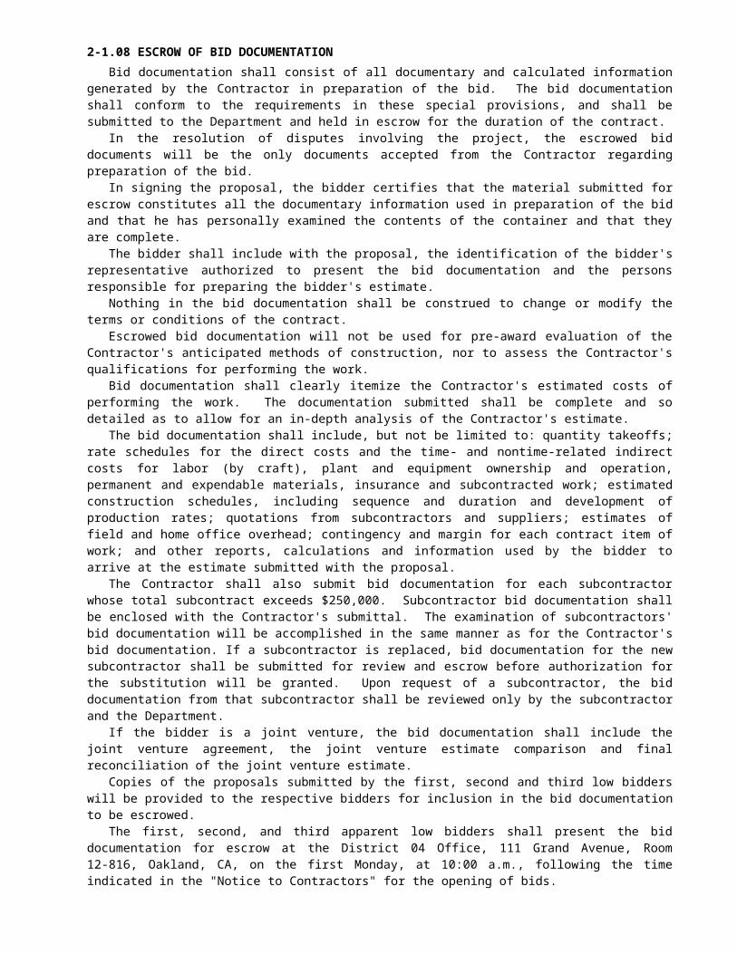
Contract No. 04-043934REVISED PER ADDENDUM NO. 3 DATED FEBRUARY 6, 1998

The earliest start date for work in the Union Pacific Railroad Company property shall be November 1, 1998 after contract award. The earliest access to an at grade crossing of the Union Pacific Railroad tracks near the Nantucket is November 1, 1998 after contract award.
It is anticipated that the following utility facilities will be relocated prior to the dates shown.
Utility Location DatePacific Bell Fiberoptics cable (abandon only within project limits)
Between Bent D5 and Pier 5, below bridge deck on eastbound structure, on face of Abutment 1
10/31/97
PG&E Gas Line (U/G) North of Abutment 1 9/22/97PG&E 22" Gas Line At Bents D2 and D3 8/15/97
PG&E Electrical Poles At Port and Wanda and Vista del Rio
10/31/97
EBMUD 8" Waterline &Fire Hydrant
Dowrelio Street at Port Street 8/28/97
In locations where paving operations will be conducted, the contractor shall reference all manholes, water valve street pots, and pull boxes in advance of the paving operation. The top of all manholes, water valve street pots and pull boxes shall be protected from the asphalt concrete during paving operations by means of plywood covers or as approved by the Engineer.
The Contractor shall notify PG&E in writing one-month prior to completing the east side retrofit work on the “A4E” Mainspan as described in “Order of Work” of these special provisions.
Installation of the following utility facilities will require coordination with the Contractor's operations. The Contractor shall make necessary arrangements with the utility company, through the Engineer, and shall submit a schedule of work, verified by a representative of the utility company, to the Engineer. The schedule of work shall provide not less than the following number of working days, as defined in Section 8-1.06, "Time of Completion," of the Standard Specifications for the utility company to complete their work.
Utility Old Location New Location Working DaysPG&E 26" Gas Pipeline (under-ground)
Port and Wanda to Bent A13E
Port and Wanda to Pier 5
see Table 1
PG&E 26” Gas Riser and Pipeline (above ground)
riser at Bent A13E, pipeline on West side of bridge, above bottom chord.
riser at Pier 5 (northeast corner) / pipeline on east side of bridge
seeTable 1
EBMUD 16" Water Line
Port Street As indicated on plans
30
Pacific Bell Ductbank Vista del Rio As indicated on plans
15
Within one month of contract approval as stated in Section 4 of these special provisions, the Contractor shall arrange coordination meetings with PG&E and EBMUD. At these meetings the Contractor shall explain to the utility companies the project schedule as it affects the relocations of their facilities.
The work by PG&E is generally as follows:
1. Install new underground pipeline between Port and Wanda and riser at Bent A13E, construct temporary connection to existing riser. Activate the new underground pipeline.(Note: P.G.&E. may begin this work prior to contract award)
2. Excavate and install pipe anchor assembly northeast of Abutment 1.3. Construct a new pipeline on hangers constructed by the Contractor. The pipe will be pushed onto the bridge
from the north end after the Contractor’s retrofit work in the bottom chord area of the east truss is completed.4. Construct a new pipeline riser at Pier 5 on hangers constructed by the Contractor, after the Contractor’s
retrofit work at Pier 5 is completed.5. Install new pipeline in 30" casing jacked under railroad tracks between Pier 5 and Bent A13E. The earliest
start date for this work is 170 working days after contract award.6. Activate the new above-ground pipe line, then remove the existing gas line on the west side of the 1958 EB
bridge and the riser at Bent A13E. No work by the Contractor in the bottom chord area of the west truss or at Bent A13E shall be done until the existing gas line and riser has been removed by PG&E.

Contract No. 04-043934REVISED PER ADDENDUM NO. 3 DATED FEBRUARY 6, 1998

The Contractor shall make available to PG&E certain areas within the project limits for the work by PG&E. The
work areas required by PG&E are generally as indicated in Table 1.No work shall be done at Port Street, at Bents D5, D6, A10E, A11E, and A12E until the new underground gas
pipeline has been installed and the old underground gas pipeline deactivated by PG&E. No work shall be done on the west truss of the 1958 bridge, at Bent A13E, or at the west side of the north abutment until the old above- ground gas pipeline has been deactivated by PG&E, nor shall work be done on the east truss, at Pier 5, or at the east side of the north abutment after the new above-ground pipeline has been activated by PG&E without the express written approval of the Engineer.
Table 1: PG&E Gas Pipeline Work Areas
LocationDescrip-tion of Work
Approx. Duration RemarkPort Street between Wanda and Dowrelio; area under and to the west of bridge from Bent A10E to A13E
Construct new underground gas pipeline and abandon old pipeline
5 weeks Must be completed before beginning of retrofit work on D5, D6, A10E, A11E, and A12E.
East shoulder north of abutment 1
Construct pipe anchor, stockpile pipe materials
10 weeks Begin after Abutment 1 work is complete 4 weeks before start of pipe installa-tion
East truss Abut 1 to Pier 5
Pipeline installation 6 weeks Begin after retrofit and pipeline hanger work completed on East Truss
Pier 5, Bent A13E Pipeline riser installa-tion and installa-tion of new pipeline under railroad tracks
2 weeks Begin after retrofit work completed in Pier 5
Median north of bridge, and west side of bridge between Abutment 1 and Bent A13E
Remove old pipeline and riser
3 weeks Must be completed before beginning of retrofit work on West Truss and Bent A13E.
The Work by EBMUD is generally as follows:
EBMUD will install a new waterline between Dowrelio Road and the intersection of Port and Wanda to replace the existing 16-inch waterline in Port Street. The Contractor shall coordinate with EBMUD to allow EBMUD to install the new pipeline prior to paving work on Wanda Street and Port Street.
The work by Pacific Bell is generally as follows:
Pacific Bell will install a new ductbank in the trench excavated by the Contractor and backfill.
This work will proceed concurrently or immediately after excavation. After the ductbank is installed, Pacific Bell will pull cable and make connections at each end and at the manhole.
In the event that the utility facilities mentioned above are not removed or relocated by the times specified and, if in the opinion of the Engineer, the Contractor's operations are delayed or interfered with by reason of the utility facilities not being removed or relocated by said times, the State will compensate the Contractor for such delays to the extent provided in Section 8-1.09, "Right of Way Delays," of the Standard Specifications, and not otherwise, except as provided in Section 8-1.10, "Utility and Non-Highway Facilities," of the Standard Specifications.

Contract No. 04-043934REVISED PER ADDENDUM NO. 3 DATED FEBRUARY 6, 1998

10-1.31C CONTAMINATED AND HAZARDOUS MATERIAL EXCAVATIONAll contaminated and hazardous material to be excavated as shown on the plans and described in these special
provisions shall be transported to a disposal facility permitted to accept such material.Attention is directed to "Contaminated and Hazardous Material, General" elsewhere in these special provisions.Attention is directed to the following tables that summarize the vertical extent, degree and type of constituents of
concern in the areas to be excavated.
West Bound Highway Shoulder and Drainage System IIZone (b.g.s.) Sample Depth
(b.g.s.)Sample
I.D.CAM 17 (mg/Kg)
WET (mg/L)
TCLP (mg/L)
Classification
0.5 foot HS-1 Pb 5.8HS-2 Pb 412 25 0.52HS-3 Pb 200 5.3 ND, ND
1 foot HS-1 Pb 11Entire Depth HS-2 Pb 78 5.8 ND Hazardous
HS-3 Pb 262 feet HS-1 Pb 27
HS-2 Pb 82 2.2HS-3 Pb 16
Sample Depth (b.g.s.)
Sample I.D.
TPH -g (mg/Kg)
TPH-d (mg/Kg)
TPH-mo (mg/Kg)
0.5 foot HS-1HS-2HS-3
1 foot HS-1HS-2HS-3
2 feet HS-1 ND 2070 NDHS-2 ND ND NDHS-3 ND ND 13, 20
Contract No. 04-043934REVISED PER ADDENDUM NO. 3 DATED FEBRUARY 6, 1998

Wanda Street (W11+05 to W14+75). Drainage System 4 (a,b,c,d,h,x), Drainage System 8, and Sanitary Sewer Systems 6, 7 and 8
Zone (b.g.s.) Sample Depth (b.g.s.)
Sample I.D.
CAM 17 (mg/Kg) WET (mg/L)
TCLP (mg/L)
Classification
M 30 Pb 191 10M 32 Pb 157 5.1M 34 Pb 304 34
0.5 foot WAN-1 Pb 396 16 0.62WAN-2 Pb 192 19 0.40WAN-3 Pb 1130,Pb 1280 88 1.3WAN-4 Pb 277 34 0.62WAN-5 Pb 199 9.4,9.0 0.25
1 foot M 31 Pb 59M 33 Pb 55
1.5 feet M 30 Pb 37M 32 Pb 45M 34 Pb 50
0 to 5 feet 2 feet M 31 Pb 29 HAZARDOUS
M 33 Pb 56M 30 Pb 53M 32 Pb 47M 34 Pb 94
3 feet WAN-1 Pb 10WAN-2 Pb 8.9WAN-3 Pb 9.3WAN-4 Pb 27WAN-5 Pb 158 6.9 0.27
M 30 Pb 555 feet WAN-1 Pb 7.3
WAN-2 Pb 16WAN-3 Pb 14 ContaminatedWAN-4 Pb 39WAN-5 Pb 40
6 feet M 32 Pb 32
Sample Depth (b.g.s.)
Sample I.D.
TPH-G (MG/KG) TPH-d (mg/Kg)
TPH-mo (mg/Kg)
0.5 WAN-1 ND C 13 CWAN-2 ND C 11 CWAN-3 ND* 264*WAN-4 ND C, ND
C424 C, 568 C
WAN-5 ND 4043 feet WAN-1 ND
WAN-2 NDWAN-3 ND ND* 264*WAN-4 NDWAN-5 ND ND** 148**
5 feet WAN-1 NDWAN-2 NDWAN-3 ND ND 32WAN-4 NDWAN-5 ND, ND ND** 148**
Contract No. 04-043934REVISED PER ADDENDUM NO. 3 DATED FEBRUARY 6, 1998

Retainin Wall, Drainage System 1 (a,b,c) and Drainage System 7Zone (b.g.s.) Sample Depth
(b.g.s.)Sample
I.D.CAM 17 (mg/Kg)
WET (mg/L)
TCLP (mg/L)
Classification
M 44 Pb 50M 46 Pb 197 9.2
0.5 foot RW-1 Pb 84 5.1, 5.1 NDRW-2 Pb 57, 47 6.1 0.25RW-3 Pb 187 15 0.22RW-4 Pb 62 6.8 ND
1 foot M 45 Pb 660 to 5 feet 1.5 feet M 44 Pb 35 Hazardous
M 46 Pb 702 feet M 45 Pb 30
M 44 Pb 12M 46 Pb 18
3 feet RW-1 Pb 8.9RW-2 Pb 19, Pb 19RW-3 Pb 210 9.5 0.38, 0.33RW-4 Pb 95 1.0M 44 Pb 16M 46 Pb 80
5 feet RW-1 Pb 20 ContaminatedRW-2 Pb 9.3RW-3 Pb 8.7RW-4 Pb 6.2
Sample Depth (b.g.s.)
Sample I.D.
EPA 8240 (ug/Kg)
EPA 8270 (ug/Kg)
TPH-g (mg/Kg)
TPH-d (mg/Kg)
TPH-mo (mg/Kg)
0.5 foot RW-1 ND* 7.6*RW-2 ND* 12*RW-3 ND 278RW-4 ND 65
3 feet RW-1 ND ND ND ND* 7.6*RW-2 ND ND ND ND* 12*RW-3 ND ND ND 376**,369** 613**,603**RW-4 ND ND ND ND** 2.9**
5 feet RW-1 ND ND ND ND 4.1RW-2 ND ND ND ND 7.1RW-3 ND ND ND 376**,369** 613**,603**RW-4 ND ND ND ND** 2.9**
Contract No. 04-043934REVISED PER ADDENDUM NO. 3 DATED FEBRUARY 6, 1998

C & H Parking AreaZone (b.g.s.) Sample Depth
(b.g.s.)Sample
I.D.CAM 17 (mg/Kg) WET
(mg/L)TCLP (mg/L)
Classification
M 17 Pb 663 42M 19 Pb 61M 21 Pb 242 6.4M 22 Pb 85
0.5 foot CH-1 Pb 305 25 0.34CH-2 Pb 342, Pb 308 25 0.31CH-3 Pb 375 21 0.48CH-4 Pb 145 1.3CH-5 Pb 313 6.2 0.28CH-6 Pb 118 2.1CH-7 Pb 58 3.3CH-8 Pb 118, Pb 319 24 0.46CH-9 Pb 174, Pb 197 8.3 0.24CH-10 Pb 465, Pb 36 1.9CH-11 Pb 50 1.3CH-12 Pb 27CH-13 Pb 84 5.6 0.72CH-14 Pb 368 15 0.25
Entire Depth 1 foot M 18 Pb 938 HazardousM 20 Pb 268 6.5M 23 Pb 105
1.5 feet M 17 Pb 211M 19 Pb 836M 21 Pb 303
2 foot M 18 Pb 339 6.5M 20 Pb 338M 17 Pb 138 5.9M 21 Pb 224 9.9
3 feet CH-1 Pb 112 6.8 0.15CH-2 Pb 30CH-3 Pb 418 24 0.43CH-4 As 84, Pb 137 As 0.27,
Pb 5.4Pb ND
CH-5 Pb 95 4.7,6.3 0.25,0.22CH-6 Pb 126 4.5CH-7 Pb 39CH-8 Pb 73 3.7CH-9 Pb 73 4.1,4.0CH-10 Pb 139 4.0CH-11 Pb 77 3.5,3.5CH-12 Pb 27CH-13 Pb 5.5, 7.7CH-14 Pb 463 26 0.86
5 feet CH-3 Pb 155 10 0.18CH-4 Pb 62 3.2CH-14
Contract No. 04-043934REVISED PER ADDENDUM NO. 3 DATED FEBRUARY 6, 1998

Sample Depth (b.g.s.)
Sample I.D.
TPH-g (mg/Kg) TPH-d (mg/Kg)
TPH-mo (mg/Kg)
0.5 foot CH-1CH-2CH-3 ND C 528 CCH-4 ND* 660*CH-5CH-6 ND,NDCH-7CH-8 NDCH-9CH-10CH-11CH-12 NDCH-13 ND 568CH-14 ND* 2000*
3 feet CH-1 ND ND 31CH-2 ND ND 111CH-3 NDCH-4 ND ND* 660*CH-5 ND ND 75CH-6 ND 146,157CH-7 ND ND 54CH-8 ND 169CH-9 ND ND 140CH-10 ND ND 171CH-11 ND ND 164CH-12 ND,ND 120CH-13 ND 13CH-14 ND ND* 2000*
5 feet CH-3 NDCH-4 ND ND 65CH-14
Contract No. 04-043934REVISED PER ADDENDUM NO. 3 DATED FEBRUARY 6, 1998

Bent A3E, Adjacent Roadway Excavation, and Drainage System 1 (d,e,f,g,h,j,p, and t)Zone (b.g.s.) Sample Depth
(b.g.s.)Sample
I.D.CAM 17 (mg/Kg) WET
(mg/L)TCLP (mg/L)
Classification
M 43 Pb 490 280.5 foot B-A3-1 Pb 8.8
0 to 3 feet B-A3-2 Pb 8.8 HazardousB-A3-3 Pb 204 23,23 0.58
1.5 feet M 43 Pb 11M 43 Pb 70
3 feet B-A3-1 Pb 8.8, 11B-A3-2 Pb 8.4B-A3-3 Pb 39 Contaminated
7 feet B-A3-1 Pb 9.0B-A3-2 Pb 6.2B-A3-3
11 feet B-A3-1 Pb 80
Sample Depth (b.g.s.)
Sample I.D.
TPH-g (mg/Kg) TPH-d (mg/Kg)
TPH-mo (mg/Kg)
0.5 foot B-A3-1 1.6 C 11 CB-A3-2 7.5 C ND CB-A3-3 ND* 813*
3 feet B-A3-1 NDB-A3-2 NDB-A3-3 ND ND* 813*
7 feet B-A3-1 NDB-A3-2 NDB-A3-3 ND ND 42
11 feet B-A3-1 ND
Contract No. 04-043934REVISED PER ADDENDUM NO. 3 DATED FEBRUARY 6, 1998

Bent A4EZone (b.g.s.) Sample Depth
(b.g.s.)Sample
I.D.CAM 17 (mg/Kg)
WET (mg/L)
TCLP (mg/L)
Classification
0 to 3 feet 0.5 foot B-A4-1 Pb 1310 Zn 0.25 HazardousB-A4-2 Pb 14
3 feet B-A4-1 Pb 21B-A4-2 Pb 14
7 feet B-A4-1 Pb 4.0 ContaminatedB-A4-2 Pb 5.6
11 feet B-A4-2 Pb 8.2
Sample Depth (b.g.s.)
Sample I.D.
EPA 8240 (ug/Kg)
EPA 8270 (ug/Kg)
TPH-g (mg/Kg)
TPH-d (mg/Kg)
TPH-mo (mg/Kg)
0.5 foot B-A4-1B-A4-2
3 feet B-A4-1 ND ND ND ND, ND 1.5,1.5B-A4-2 ND, ND ND ND, ND ND 23
7 feet B-A4-1 ND, ND ND ND ND 2.8B-A4-2 ND ND, ND ND ND ND
11 feet B-A4-2 ND ND ND ND ND
Contract No. 04-043934REVISED PER ADDENDUM NO. 3 DATED FEBRUARY 6, 1998

Bent A5EZone (b.g.s.) Sample Depth
(b.g.s.)Sample
I.D.CAM 17 (mg/Kg)
WET (mg/L)
TCLP (mg/L)
Classification
0.5 foot B-A5-1 Pb 6.1B-A5-2 Pb 3.0B-A5-3 Pb 4.7
3 feet B-A5-1 Pb 153 2.7B-A5-2 Pb 7.3
Entire Depth B-A5-3 Pb 7.8 Contaminated7 feet B-A5-1 Pb 4.6
B-A5-2 Pb 6.4B-A5-3 Pb 9.4
11 feet B-A5-1 NDB-A5-2 Pb 8.5B-A5-3 Pb 121 2.4
15 feet B-A5-2 Pb 6.7
Sample Depth (b.g.s.)
Sample I.D.
EPA 8240 (ug/Kg)
EPA 8270 (ug/Kg)
TPH-g (mg/Kg)
TPH-d (mg/Kg)
TPH-mo (mg/Kg)
0.5 foot B-A5-1B-A5-2 4.0 CB-A5-3 ND C 15C
3 feet B-A5-1 ND ND, ND ND ND 18B-A5-2 NDB-A5-3 ND
7 feet B-A5-1 ND ND ND ND NDB-A5-2 NDB-A5-3 ND
11 feet B-A5-1 ND ND ND ND, ND 3.8,2.8B-A5-2 NDB-A5-3 ND
15 feet B-A5-2 ND
Contract No. 04-043934REVISED PER ADDENDUM NO. 3 DATED FEBRUARY 6, 1998

Bent A6EZone (b.g.s.) Sample Depth
(b.g.s.)Sample
I.D.CAM 17 (mg/Kg) WET
(mg/L)TCLP (mg/L)
Classification
0.5 foot B-A6-1 Pb 22B-A6-2 Pb 31B-A6-3 Pb 146 6.4 0.18
3 feet B-A6-1 Pb 180 to 11 feet B-A6-2 Pb 25, 20 Hazardous
B-A6-3 Pb 80 5.0 0.257 feet B-A6-1 Pb 253 6.7 0.49
B-A6-2 Pb 6.4B-A6-3 Pb 9.0
11 feet B-A6-2 Pb 6.3B-A6-3 Pb 5.9 Contaminated
15 feet B-A6-3 Pb 5.2
Sample Depth (b.g.s.)
Sample I.D.
TPH-g (mg/Kg) TPH-d (mg/Kg)
TPH-mo (mg/Kg)
0.5 foot B-A6-1 ND C 83 CB-A6-2 ND C,
ND C10 C, 7.9C
B-A6-3 ND C 750 C3 feet B-A6-1 ND
B-A6-2 ND, NDB-A6-3 ND, ND
7 feet B-A6-1 ND, NDB-A6-2 NDB-A6-3 ND
11 feet B-A6-2 NDB-A6-3 ND
15 feet B-A6-3 ND
Contract No. 04-043934REVISED PER ADDENDUM NO. 3 DATED FEBRUARY 6, 1998

Bent A7EZone (b.g.s.) Sample Depth
(b.g.s.)Sample
I.D.CAM 17 (mg/Kg) WET
(mg/L)TCLP (mg/L)
Classification
0.5 foot B-A7-1 Pb 58, 31 3.4B-A7-2 Pb 9.3B-A7-3 Pb 35
3 feet B-A7-1 Pb 20B-A7-2 Pb 30B-A7-3 Pb 15
Entire Depth 7 feet B-A7-1 Pb 8.7 ContaminatedB-A7-2 Pb 11B-A7-3 Pb 25
11 feet B-A7-2 Pb 57 2.4B-A7-3 Pb 38
15 feet B-A7-3 Pb 4.6
Sample Depth (b.g.s.)
Sample I.D.
TPH-g (mg/Kg) TPH-d (mg/Kg)
TPH-mo (mg/Kg)
0.5 foot B-A7-1 ND C 25 CB-A7-2 ND C 43 CB-A7-3 ND C 18 C
3 feet B-A7-1 NDB-A7-2 NDB-A7-3 ND
7 feet B-A7-1 NDB-A7-2 NDB-A7-3 ND
11 feet B-A7-2 NDB-A7-3 ND
15 feet B-A7-3 ND
Contract No. 04-043934REVISED PER ADDENDUM NO. 3 DATED FEBRUARY 6, 1998
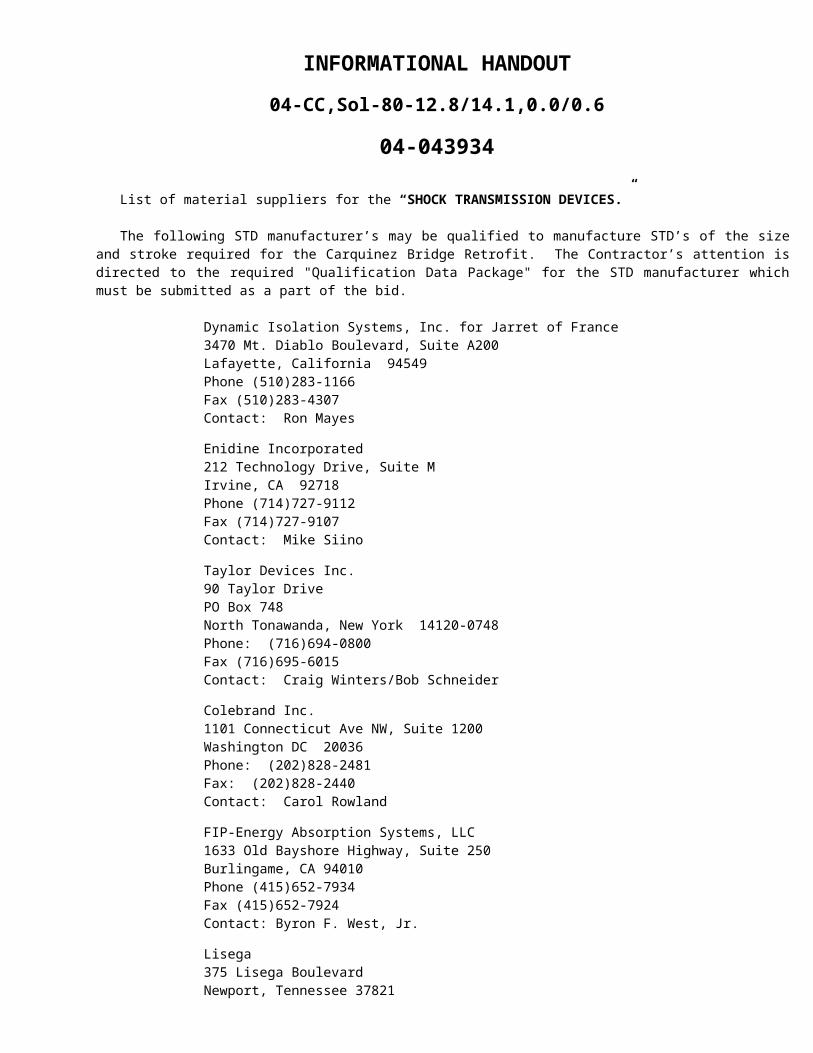
Bent A8EZone (b.g.s.) Sample Depth
(b.g.s.)Sample
I.D.CAM 17 (mg/Kg) WET
(mg/L)TCLP (mg/L)
Classification
0.5 foot B-A8-1 Pb 32B-A8-2 Pb 9.1
0 to 7 feet B-A8-3 Pb 268 18 0.31 Hazardous3 feet B-A8-1 Pb 6.1
B-A8-2 Pb 6.3, 6.5B-A8-3 Pb 456 29 0.83
7 feet B-A8-1 Pb 5.5B-A8-2 Pb 8.0B-A8-3 Pb 5.7 Contaminated
11 feet B-A8-1 Pb 65 1.9B-A8-2 Pb 8.3B-A8-3 Pb 19
Sample Depth (b.g.s.)
Sample I.D.
TPH-g (mg/Kg) TPH-d (mg/Kg)
TPH-mo (mg/Kg)
0.5 foot B-A8-1 ND C 15 CB-A8-2 ND C 6.4 CB-A8-3 ND C 75 C
3 feet B-A8-1 NDB-A8-2 NDB-A8-3 ND
7 feet B-A8-1 ND, NDB-A8-2 NDB-A8-3 ND
11 feet B-A8-1 NDB-A8-2 NDB-A8-3 ND
Contract No. 04-043934REVISED PER ADDENDUM NO. 3 DATED FEBRUARY 6, 1998

Bent D2Zone (b.g.s.) Sample Depth
(b.g.s.)Sample
I.D.CAM 17 (mg/Kg) WET
(mg/L)TCLP (mg/L)
Classification
0.5 foot B-D2-1 Pb 5.80 to 7 feet B-D2-2 Pb 914 96.15 4.9, 3.2 Hazardous
3 feet B-D2-1 Pb 10B-D2-2 Pb 724 36.18 0.38, 0.24
7 feet B-D2-1 Pb 8.8B-D2-2 Pb 8.8 Contaminated
11 feet B-D2-1 Pb 8.2B-D2-2 Pb 6.7
Sample Depth (b.g.s.)
Sample I.D.
TPH-g (mg/Kg) TPH-d (mg/Kg)
TPH-mo (mg/Kg)
0.5 foot B-D2-1 ND C 357 CB-D2-2 ND C 253 C
3 feet B-D2-1 NDB-D2-2 ND
7 feet B-D2-1 NDB-D2-2 ND, ND
11 feet B-D2-1 NDB-D2-2 ND
Bent D3Zone (b.g.s.) Sample Depth
(b.g.s.)Sample
I.D.CAM 17 (mg/Kg) WET
(mg/L)TCLP (mg/L)
Classification
0.5 foot B-D3-1 Pb 123 feet B-D3-1 Pb 50, Pb 135 3.7
Entire Depth 7 feet B-D3-1 Pb 8.3 Contaminated11 feet B-D3-1 Pb 3.315 feet B-D3-1 Pb 4.5
Sample Depth (b.g.s.)
Sample I.D.
TPH-g (mg/Kg) TPH-d (mg/Kg)
TPH-mo (mg/Kg)
0.5 foot B-D3-1 ND C 7.2 C3 feet B-D3-1 ND7 feet B-D3-1 ND11 feet B-D3-1 ND15 feet B-D3-1 ND
Contract No. 04-043934REVISED PER ADDENDUM NO. 3 DATED FEBRUARY 6, 1998

Bent D4Zone (b.g.s.) Sample Depth
(b.g.s.)Sample
I.D.CAM 17 (mg/Kg)
WET (mg/L)
TCLP (mg/L)
Classification
0.5 foot PRO-4 Pb 7.4, Pb 6.23 feet PRO-4 Pb105 83,83 ND Hazardous7 feet PRO-4 Pb 6.2 Contaminated
Sample Depth (b.g.s.)
Sample I.D.
EPA 8240 (ug/Kg)
EPA 8270 (ug/Kg)
TPH-g (mg/Kg)
TPH-d (mg/Kg)
TPH-mo (mg/Kg)
0.5 foot PRO-4 ND C ND C 5.2 C3 feet PRO-4 ND ND C ND7 feet PRO-4 ND ND C ND
Plaza Detour & Drainage System 6Zone (b.g.s.) Sample Depth
(b.g.s.)Sample
I.D.CAM 17 (mg/Kg) WET
(mg/L)TCLP (mg/L)
Classification
DE-1 Pb 120.5 foot DE-2 Pb 7.2, Pb 15
DE-3 Pb 32, Pb 26DE-4 Pb 33, Pb 32DE-1 Pb 15
Entire Depth 3 feet DE-2 Pb 5.9 ContaminatedDE-3 Pb 30DE-4 Pb 1.6DE-1 Pb 8.4
7 feet DE-2 Pb 15, Pb 14DE-3 Pb 38DE-4 Pb 4.6
Sample Depth (b.g.s.)
Sample I.D.
TPH-g (mg/Kg) TPH-d (mg/Kg)
TPH-mo (mg/Kg)
DE-1 ND* 137*0.5 foot DE-2
DE-3 ND* 367*DE-4DE-1 ND, ND ND* 137*
3 feet DE-2 ND ND** 253*DE-3 ND ND* 367*DE-4 ND ND**,
ND**71**, 71**
DE-1 ND, ND ND 3.77 feet DE-2 ND ND** 253**
DE-3 ND ND 175DE-4 ND ND**,
ND**71**, 71**
Contract No. 04-043934REVISED PER ADDENDUM NO. 3 DATED FEBRUARY 6, 1998

Port Street Realignment & Drainage System 5 (a-e) and 4 (n,l,r,s,g)Zone
(b.g.s.)Sample Depth
(b.g.s.)Sample
I.D.CAM 17 (mg/Kg) WET (mg/L) TCLP (mg/L) Classification
M 25 Pb 243M 27 PB 684 47M 28 Pb 109 2.8M 29 Pb 131 2.4
0.5 foot POR-2 As 311, Pb 1130 As 7.5, Pb 69 As 0.37, Pb 0.97, 0.97
POR-3 Pb 98 3.81 feet M 26 Pb 578
1.5 feet M 25 Pb 412 36M 27 Pb 49M28 Pb 35M 29 Pb 30M 26 Pb113 36
Entire Depth
2 feet POR-3 As 62, Pb 336 As 0.33, Pb 9.9
Pb 0.31 Hazardous
M 25 Pb 27M 27 Pb 127 5.4M 28 Pb 65M 29 Pb 30
3 feet POR-2 Pb 647, Pb 432 15, 16 0.344 feet M 29 Pb 135
M 28 Pb 161 6.55 feet POR-2 As 376, Pb 797 As 6.1, Pb 29 As 0.14,
Pb 0.556 feet M 27 Pb 51
Sample Depth (b.g.s.)
Sample I.D.
TPH-g (mg/Kg) TPH-d (mg/Kg)
TPH-mo (mg/Kg)
0.5 foot POR-2POR-3
2 feet POR-3 ND ND 2403 feet POR-2 ND, ND5 feet POR-2 ND ND 343
Contract No. 04-043934REVISED PER ADDENDUM NO. 3 DATED FEBRUARY 6, 1998

Ceres St. (CR 10+00 to 12+83) & Drainage System 2 (d, e, f, h, k, and m)Zone (b.g.s.) Sample Depth
(b.g.s.)Sample
I.D.CAM 17 (mg/Kg)
WET (mg/L)
TCLP (mg/L)
Classification
M 38 Pb 375 160.5 foot CR-1 Pb 232 19 0.22
CR-2 Pb 84 2.61 foot M 39 Pb 60
0 to 3 feet M 40 Pb 59 HazardousM 41 Pb 34
1.5 feet M 38 Pb 215 8.12 feet M 39 Pb 92
M 40 Pb 49M 41 Pb 43M 38 Pb 85
3 feet CR-1 Pb 4.5CR-2 Pb9.0
6 feet M 38 Pb 42 Contaminated7 feet CR-1 Pb 8.5
CR-2 Pb 6.811 feet CR-1 Pb 12
CR-2 Pb 8.3
Sample Depth (b.g.s.)
Sample I.D.
EPA 8240 (ug/Kg)
EPA 8270 (ug/Kg)
TPH-g (mg/Kg)
TPH-d (mg/Kg)
TPH-mo (mg/Kg)
0.5 foot CR-1CR-2
3 feet CR-1 ND ND ND ND NDCR-2 ND ND ND ND ND
7 feet CR-1 ND ND ND ND NDCR-2 ND ND ND ND, ND ND, ND
11 feet CR-1 ND ND ND ND NDCR-2 ND ND ND ND ND
Contract No. 04-043934REVISED PER ADDENDUM NO. 3 DATED FEBRUARY 6, 1998

Pomona St. (PM 12+24 to PM 13+10)Zone (b.g.s.) Sample Depth
(b.g.s.)Sample
I.D.CAM 17 (mg/Kg)
WET (mg/L)
TCLP (mg/L)
Classification
POM-1 Pb 2.80 to 3 feet 0.5 foot POM-2 Pb 256, Pb 47 11 0.22, 0.22 Hazardous
POM-1 Pb 69, Pb 98 1.33 foot POM-2 Pb 14 Contaminated
POM-1 Pb 8.25 feet POM-2 Pb 12
Sample Depth (b.g.s.)
Sample I.D. EPA 8240 (ug/Kg)
EPA 8270 (ug/Kg)
TPH-g (mg/Kg)
TPH-d (mg/Kg)
TPH-mo (mg/Kg)
0.5 foot POM-1 ND 313 feet POM-1 ND ND ND 42** 544**
POM-2 ND ND ND 2.3 275 feet POM-1 ND, ND ND ND 42** 544**
POM-2 ND, ND ND ND ND ND
Drainage System 3Zone (b.g.s.) Sample Depth
(b.g.s.)Sample
I.D.CAM 17 (mg/Kg) WET
(mg/L)TCLP (mg/L)
Classification
M 35 Pb 331 18M 36 Pb.137 9.5M 37 Pb 822
0.5 foot CR-3 Pb 111 1.3CR-4 Pb 18
1.5 feet M 35 Pb 640 to 6 feet M 36 Pb 106 Hazardous
M 37 Pb 121M 35 Pb 98M 36 Pb 39M 37 Pb 126 5.5
3 feet CR-3 Pb 3.3CR-4 Pb 12
6 feet M 35 Pb 75M 36 Pb 37M 37 Pb 80 Contaminated
7 feet CR-3 Pb 200 2.0CR-4 PB 38
11 feet CR-3 PB 6.5, PB 5.7CR-4 PB 7.2, PB 7.4
Sample Depth (b.g.s.)
Sample I.D.
TPH-g (mg/Kg) TPH-d (mg/Kg)
TPH-mo (mg/Kg)
0.5 foot CR-3 ND C 73 CCR-4 ND C 8.0 C
3 feet CR-3 NDCR-4 ND
7 feet CR-3 NDCR-4 ND
11 feet CR-3 NDCR-4 ND
Contract No. 04-043934REVISED PER ADDENDUM NO. 3 DATED FEBRUARY 6, 1998

Drainage System 2 (a, b, and c)Zone (b.g.s.) Sample Depth
(b.g.s.)Sample
I.D.CAM 17 (mg/Kg) WET
(mg/L)TCLP (mg/L)
Classification
0.5 foot M 42 Pb 650 to 3 feet 1.5 feet M 42 Pb 168 14 Hazardous
3 feet M 42 Pb 55 Contaminated6 feet M 42 Pb 73
Pier 5Zone (b.g.s.) Sample Depth
(b.g.s.)Sample
I.D.CAM 17 (mg/Kg) WET
(mg/L)TCLP (mg/L)
Classification
0.5 foot M 15 Pb 382 32 2.5M 16 Pb 146 5.0
0 to 6 feet 1.5 feet M 15 Pb 1100 HazardousM 16 Pb 1040 0.65
3 feet M 15 Pb 106M 16 Pb 135
6 feet M 15 Pb 68 ContaminatedM 16 Pb 38
Bent A9EZone (b.g.s.) Sample Depth
(b.g.s.)Sample
I.D.CAM 17 (mg/Kg) WET
(mg/L)TCLP (mg/L)
Classification
0.5 foot P-A9-1 Pb 430 15 NDP-A9-2 Pb 120 5.9 NDP-A9-3 Pb 320 10 ND
2.5 feet P-A9-1 Pb 100, Pb 110 4.5P-A9-2 Pb 40
Entire Depth P-A9-3 Pb 9.1 Hazardous6.5 feet P-A9-1 Pb 11
P-A9-2 Pb 8.2, Pb 6.2P-A9-3 Pb 21
10.5 feet P-A9-1 Pb 27P-A9-2 Pb 1500 ND
Sample Depth (b.g.s.)
Sample I.D.
EPA 8240 (ug/Kg)
TPH-g (mg/Kg)
TPH-d (mg/Kg)
TPH-mo (mg/Kg)
0.5 foot P-A9-1 ND ND ND C ND CP-A9-2 ND ND ND C 37 CP-A9-3 ND ND ND C ND C
2.5 feet P-A9-1 ND, ND ND, NDP-A9-2 ND NDP-A9-3 ND ND
6.5 feet P-A9-1 ND NDP-A9-2 ND, ND ND, NDP-A9-3 Carbon Disulfide 29 ND
10.5 feet P-A9-1 ND NDP-A9-2 ND ND
Contract No. 04-043934REVISED PER ADDENDUM NO. 3 DATED FEBRUARY 6, 1998

Bent A10EZone (b.g.s.) Sample Depth
(b.g.s.)Sample
I.D.CAM 17 (mg/Kg) WET (mg/L) TCLP
(mg/L)Classification
0.5 foot P-A10G-1 Cr 57, Pb 130 Cr ND, Pb 10 Pb NDP-A10-2 Pb 150 21 NDP-A10-3 Pb 2.7
2.5 feet P-A10G-1 Pb 91 460 2.50 to 10.5 feet P-A10-2 Pb 25 Hazardous
P-A10-3 Pb.50 1.56.5 feet P-A10G-1 Pb 83 5.4 ND
P-A10-2 Pb 60 4.4P-A10-3 Pb 11
10.5 feet P-A10G-1 Pb 8.4P-A10-2 Pb 15 ContaminatedP-A10-3 Pb 12
Sample Depth (b.g.s.)
Sample I.D.
EPA 8240 (ug/Kg)
TPH-g (mg/Kg)
TPH-d (mg/Kg)
TPH-mo (mg/Kg)
0.5 foot P-A10G-1 ND ND 26 C 68 CP-A10-2 ND ND ND C ND CP-A10-3 ND, ND ND, ND ND C ND C
2.5 feet P-A10G-1 ND NDP-A10-2 ND NDP-A10-3 ND ND
6.5 feet P-A10G-1 ND NDP-A10-2 ND NDP-A10-3 ND ND
10.5 feet P-A10G-1 66 DCMethane NDP-A10-2 ND NDP-A10-3 ND ND
Contract No. 04-043934REVISED PER ADDENDUM NO. 3 DATED FEBRUARY 6, 1998

Bent A11EZone (b.g.s.) Sample Depth
(b.g.s.)Sample
I.D.CAM 17 (mg/Kg) WET
(mg/L)TCLP (mg/L)
Classification
0.5 foot P-A11G-1 Pb 210 17 NDP-A11-2 Pb 85 3.9P-A11-3 Pb 160, Pb 150 8.7 ND
2.5 feet P-A11G-1 Pb 360 to 10.5 feet P-A11-2 Pb 180, Pb 140 8.8, 11 ND Hazardous
P-A11-3 Pb 146.5 feet P-A11G-1 Pb.13
P-A11-2 Pb 680 38 NDP-A11-3 Pb.110 5.1 ND
10.5 feet P-A11G-1 Pb.51 1.3 Contamined
Sample Depth (b.g.s.)
Sample I.D.
EPA 8240 (ug/Kg)
TPH-g (mg/Kg)
TPH-d (mg/Kg)
TPH-mo (mg/Kg)
0.5 foot P-A11G-1 ND ND ND C 57 CP-A11-2 ND ND ND C 240 CP-A11-3 ND, ND ND, ND ND C 59 C
2.5 feet P-A11G-1 ND NDP-A11-2 ND, ND ND, NDP-A11-3 ND ND
6.5 feet P-A11G-1 ND NDP-A11-2 ND NDP-A11-3 ND ND
10.5 feet P-A11G-1 ND ND
Contract No. 04-043934REVISED PER ADDENDUM NO. 3 DATED FEBRUARY 6, 1998

Bent A12EZone (b.g.s.) Sample Depth
(b.g.s.)Sample
I.D.CAM 17 (mg/Kg) WET (mg/L) TCLP
(mg/L)Classification
0.5 foot P-A12G-1 Pb 90 19 NDP-A12-2 Pb.150 4.0P-A12-3 Pb 630 38 ND
2.5 feet P-A12G-1 Pb 260 to 10.5 feet P-A12-2 Pb 150 3.0 Hazardous
P-A12-3 Pb 75, Pb 92 13 ND6.5 feet P-A12G-1 Pb.14
P-A12-2 Pb 150, Pb 120 12 NDP-A12-3 Cu 320, Pb 8200 Ba 22, Cu ND Pb 5.4
10.5 feet P-A12G-1 Pb.95 1.6 Contamined
Sample Depth (b.g.s.)
Sample I.D.
EPA 8240 (ug/Kg)
TPH-g (mg/Kg)
TPH-d (mg/Kg)
TPH-mo (mg/Kg)
0.5 foot P-A12G-1 ND ND 190 C 250 CP-A12-2 ND ND ND C 77 CP-A12-3 ND ND 81 C 200 C
2.5 feet P-A12G-1 ND NDP-A12-2 ND NDP-A12-3 ND, ND ND, ND
6.5 feet P-A12G-1 ND NDP-A12-2 ND, ND ND, NDP-A12-3 ND ND
10.5 feet P-A12G-1 ND ND
Bent A13EZone (b.g.s.) Sample Depth
(b.g.s.)Sample
I.D.CAM 17 (mg/Kg) WET (mg/L) TCLP
(mg/L)Classification
0.5 foot P-A13-1 Pb 480 Pb 40, Cu 8.3, Ba 9.1
Pb ND
P-A13-2 Pb 290 27 NDP-A13G-3 Pb 14
2.5 feet P-A13-1 Pb 31Entire Depth P-A13-2 Pb.300 16 0.7 Hazardous
P-A13G-3 Ba 3100, Pb 590 Ba 20, Pb 65 Pb ND6.5 feet P-A13-1 Pb 210 7.8 ND
P-A13-2 Pb.15P-A13G-3 Cu 350, Pb 2700,
Zn 6300Cu ND Pb 0.56,
Zn 48
Sample Depth (b.g.s.)
Sample I.D.
EPA 8240 (ug/Kg)
TPH-g (mg/Kg)
TPH-d (mg/Kg)
TPH-mo (mg/Kg)
0.5 foot P-A13-1 ND ND ND C ND CP-A13-2 ND ND 170 C 250 C
P-A13G-3 ND ND ND C ND C2.5 feet P-A13-1 ND ND
P-A13-2 ND NDP-A13G-3 ND ND
6.5 feet P-A13-1 ND NDP-A13-2 ND ND
P-A13G-3 ND ND ND ND
Contract No. 04-043934REVISED PER ADDENDUM NO. 3 DATED FEBRUARY 6, 1998
Bent D5Zone (b.g.s.) Sample Depth
(b.g.s.)Sample
I.D.CAM 17 (mg/Kg) WET
(mg/L)TCLP (mg/L)
Classification
0.5 feet P-D5-1 Pb NDP-D5-2 Pb 28
0 to 6.5 feet 3.0 feet P-D5-1 Pb 130, Pb 140 11 ND HazardousP-D5-2 Pb 34
6.5 feet P-D5-1 Pb 8.3 ContaminatedP-D5-2 Pb 21
Sample Depth (b.g.s.)
Sample I.D.
EPA 8240 (ug/Kg)
TPH-g (mg/Kg)
TPH-d (mg/Kg)
TPH-mo (mg/Kg)
0.5 feet P-D5-1 ND ND ND C ND CP-D5-2 ND ND ND C ND C
2.5 feet P-D5-1 ND, ND ND, NDP-D5-2 ND ND
6.5 feet P-D5-1 ND NDP-D5-2 ND ND
Bent D6Zone (b.g.s.) Sample Depth
(b.g.s.)Sample
I.D.CAM 17 (mg/Kg) WET
(mg/L)TCLP (mg/L)
Classification
0.5 foot P-D6-1 Pb 220 5.2 NDP-D6-2
2.5 feet P-D6-1 Pb 240 7.5 NDP-D6-2
Entire Depth 6.5 feet P-D6-1 Pb 96 1.5 HazardousP-D6-2
10.5 feet P-D6-1 Pb 180 69 NDP-D6-2
Sample Depth (b.g.s.)
Sample I.D.
EPA 8240 (ug/Kg)
TPH-g (mg/Kg)
TPH-d (mg/Kg)
TPH-mo (mg/Kg)
0.5 foot P-D6-1 ND ND ND C ND CP-D6-2
2.5 feet P-D6-1 ND NDP-D6-2
6.5 feet P-D6-1 ND NDP-D6-2
10.5 feet P-D6-1 ND NDP-D6-2
Contract No. 04-043934REVISED PER ADDENDUM NO. 3 DATED FEBRUARY 6, 1998

KeyC - composite of samples taken at all depths* composite of samples taken at 0.5' and 3'** composite of samples taken at 3' and 5' or 3' and 7'56, 59 - Results offset by a comma indicate a duplicate analysisND - Not DetectedCAM 17 - California 17 metals as defined in Title 22WET - Waste Extraction TestTCLP - Total Characteristic Leaching ProcedureTPH-g-d-mo - Total petroleum hydrocarbons, gas, diesel, and motor oil rangesEPA 8240 - Analysis used for detection of volatile organic compoundsEPA 8270 - Analysis used for detection of semi- volatile organic compoundsDCMethane - DichloromethaneEPA - Environmental Protection Agencyb.g.s. - below ground surfaceHazardous - Results indicate that the zone contains hazardous material as defined in Title 22Contaminated - Results indicate that the zone contains material that is suitable for disposal within a Class II Landfill
Upon completion of hazardous material excavation, temporary chain link security fence and personal protective equipment, when no longer required, as determined by the Engineer, shall be removed from the job site.
The Contractor shall implement a plan to prevent exposure of personnel working in hazardous material excavations. The Contractor's plan to prevent exposure of personnel shall consist of a physical barrier. The barrier shall be maintained by the Contractor. When no longer required, as determined by the Engineer, the physical barrier shall be removed and either decontaminated or disposed of by the Contractor. The Contractor shall prevent the flow of surface water and ground water from entering any excavation in accordance with “Non-Storm Water Discharges” of these special provisions.
MEASUREMENT AND PAYMENT.--Full compensation for loading, transporting, and disposing of contaminated and hazardous material, furnishing, installing and removing physical barriers, shall be considered as included in the contract price paid per cubic yard for structure excavation of the types designated in the Engineer's Estimate and no additional compensation will be allowed therefor.
Contract No. 04-043934REVISED PER ADDENDUM NO. 3 DATED FEBRUARY 6, 1998

10-1.31F DUCTBANK EXCAVATIONDuctbank excavation shall consist of all excavation required for the construction by others of the new telephone
ductbank as shown on the plans. The excavation work shall be performed concurrently with other work on Vista del Rio which involves closing the road to traffic.
Attention is directed to "Maintaining Traffic" and "Obstructions" of these special provisions.Ductbank excavation shall be performed in accordance with "Contaminated and Hazardous Material Excavation"
of these special provisions.The Contractor shall notify the Engineer three weeks in advance of commencing ductbank excavation work, and
shall coordinate with Pacific Bell during the excavation work.Ductbank excavation will be measured and paid for as roadway excavation (Hazardous Material).
CONTRACT NO. 04-043934ADDED PER ADDENDUM NO. 3 DATED FEBRUARY 6, 1998

ENGINEER'S ESTIMATE04-043934
Item Item Code
Item Unit of Measure
Estimated Quantity
Unit Price Item Total
1 070010 PROGRESS SCHEDULE (CRITICAL PATH)
LS LUMP SUM LUMP SUM
2(S)
011304 TEMPORARY HIGH VISIBILITY BOUNDARY FENCE
LF 1,440
3(S)
071321 TEMPORARY FENCE (TYPE CL-6) LF 1,590
4(S)
011305 TEMPORARY SILT FENCE LF 1,450
5 046811 TEMPORARY DECK BRIDGING LS LUMP SUM LUMP SUM
6(S)
074019 PREPARE STORM WATER POLLUTION PREVENTION PLAN
LS LUMP SUM LUMP SUM
7(S)
074020 WATER POLLUTION CONTROL LS LUMP SUM LUMP SUM
8(S)
011306 TEMPORARY DRAINAGE INLET PROTECTION
EA 32
9(S)
011307 TEMPORARY STOCKPILE COVER SQYD 2,100
10 011308 ELECTRONIC MOBILE DAILY DIARY COMPUTER SYSTEM
LS LUMP SUM LUMP SUM
11 011309 ELECTRONIC MOBILE DAILY DIARY SYSTEM DATA DELIVERY
LS LUMP SUM LUMP SUM
12(S)
120090 CONSTRUCTION AREA SIGNS LS LUMP SUM LUMP SUM
13(S)
120100 TRAFFIC CONTROL SYSTEM LS LUMP SUM LUMP SUM
14(S)
011310 TRAFFIC CONTROL (CROSSOVER DETOUR)
EA 160
15 120120 TYPE III BARRICADE EA 59
16 120151 TEMPORARY TRAFFIC STRIPE (TAPE)
LF 6,480
17 120165 CHANNELIZER (SURFACE MOUNTED)
EA 510
18 120300 TEMPORARY PAVEMENT MARKER EA 1,290
19(S)
121140 TEMPORARY METAL BEAM GUARD RAILING
LF 150
20(S)
011311 TEMPORARY ANCHOR ASSEMBLY (BREAKAWAY, TYPE M)
EA 2
3REVISED PER ADDENDUM NO. 3 DATED FEBRUARY 6, 1998

ENGINEER'S ESTIMATE04-043934
Item Item Code
Item Unit of Measure
Estimated Quantity
Unit Price Item Total
21(S)
121146 TEMPORARY CABLE ANCHOR ASSEMBLY (BREAKAWAY, TYPE B)
EA 2
22(S)
011312 TEMPORARY TERMINAL SECTION (TYPE M)
EA 2
23 128650 PORTABLE CHANGEABLE MESSAGE SIGN
EA 5
24 129000 TEMPORARY RAILING (TYPE K) LF 12,400
25 011313 MOVEABLE CONCRETE BARRIER LF 5,610
26 129100 TEMPORARY CRASH CUSHION MODULE
EA 50
27 046812 RESET BENCHMARK EA 14
28 046813 SALVAGE AND REINSTALL STRUCTURAL ELEMENT (LOCATION B)
LS LUMP SUM LUMP SUM
29 046814 SALVAGE AND REINSTALL STRUCTURAL ELEMENT (LOCATION C)
LS LUMP SUM LUMP SUM
30 046815 TEMPORARY ACCESS OPENING EA 63
31 046816 PERMANENT ACCESS OPENING EA 17
32 150206 ABANDON CULVERT EA 10
33(S)
046817 WORK AREA MONITORING (LOCATION A)
LS LUMP SUM LUMP SUM
34(S)
046818 WORK AREA MONITORING (LOCATION B)
LS LUMP SUM LUMP SUM
35(S)
046819 WORK AREA MONITORING (LOCATION C)
LS LUMP SUM LUMP SUM
36 150305 OBLITERATE SURFACING SQYD 830
37 150608 REMOVE CHAIN LINK FENCE LF 170
38 150662 REMOVE METAL BEAM GUARD RAILING
LF 160
39 150667 REMOVE DOUBLE METAL BEAM BARRIER
LF 3,820
40 150711 REMOVE PAINTED TRAFFIC STRIPE
LF 42,600
4REVISED PER ADDENDUM NO. 3 DATED FEBRUARY 6, 1998

ENGINEER'S ESTIMATE04-043934
Item Item Code
Item Unit of Measure
Estimated Quantity
Unit Price Item Total
41 150712 REMOVE PAINTED PAVEMENT MARKING
SQFT 880
42 150714 REMOVE THERMOPLASTIC TRAFFIC STRIPE
LF 13,700
43 150722 REMOVE PAVEMENT MARKER EA 8,470
44 150742 REMOVE ROADSIDE SIGN EA 5
45 150805 REMOVE CULVERT LF 660
46 150820 REMOVE INLET EA 12
47 150830 REMOVE RETAINING WALL (PORTION)
CY 32
48 151540 RECONSTRUCT CHAIN LINK FENCE
LF 220
49 011314 RESET PARKING BUMPER EA 17
50 152390 RELOCATE ROADSIDE SIGN EA 8
51(S)
011315 PLANE ASPHALT CONCRETE PAVEMENT (0.17' MAXIMUM)
SQYD 830
52(S)
011316 PLANE ASPHALT CONCRETE PAVEMENT (0.20' MAXIMUM)
SQYD 7,250
53 153214 REMOVE CONCRETE CURB LF 2,780
54(F)
156560 REMOVE STRUCTURAL STEEL LB 1,446,900
55 157561 BRIDGE REMOVAL (PORTION), LOCATION A
LS LUMP SUM LUMP SUM
56 157562 BRIDGE REMOVAL (PORTION), LOCATION B
LS LUMP SUM LUMP SUM
57 157563 BRIDGE REMOVAL (PORTION), LOCATION C
LS LUMP SUM LUMP SUM
58(S)
011317 BRIDGE UTILITY AND MAINTENANCE EQUIPMENT WORK
LS LUMP SUM LUMP SUM
59(S)
159102 RAISE BRIDGE, LOCATION A LS LUMP SUM LUMP SUM
60(S)
159103 RAISE BRIDGE, LOCATION B LS LUMP SUM LUMP SUM
5REVISED PER ADDENDUM NO. 3 DATED FEBRUARY 6, 1998

ENGINEER'S ESTIMATE04-043934
Item Item Code
Item Unit of Measure
Estimated Quantity
Unit Price Item Total
61(S)
159104 RAISE BRIDGE, LOCATION C LS LUMP SUM LUMP SUM
62 160101 CLEARING AND GRUBBING LS LUMP SUM LUMP SUM
63 170101 DEVELOP WATER SUPPLY LS LUMP SUM LUMP SUM
64 190101 ROADWAY EXCAVATION CY 2,250
65 011318 ROADWAY EXCAVATION (HAZARDOUS MATERIAL)
CY 3,180
66 011319 DRAINAGE EXCAVATION (HAZARDOUS)
CY 1,350
67(S)
011320 SANITARY SEWER EXCAVATION (HAZARDOUS)
CY 500
68(F)
192003 STRUCTURE EXCAVATION (BRIDGE)
CY 832
69(S)
011916 WATER CONTROL LS LUMP SUM LUMP SUM
70 047079 STRUCTURE EXCAVATION (CONTAMINATED)
CY 1,598
71(F)
192021 STRUCTURE EXCAVATION (TYPE DH)
CY 3,035
72(F)
192023 STRUCTURE EXCAVATION (TYPE H)
CY 2,145
73(S-F)
011321 STRUCTURE EXCAVATION (RETAINING WALL, TYPE H)
CY 370
74(F)
193003 STRUCTURE BACKFILL (BRIDGE) CY 2,141
75(S-F)
193013 STRUCTURE BACKFILL (RETAINING WALL)
CY 280
76 011322 DRAINAGE BACKFILL(CLASS 3 AB) CY 820
77 011323 DRAINAGE BACKFILL (IMPORTED BORROW)
CY 910
78(S)
011324 SANITARY SEWER BACKFILL (CLASS 3 AB)
CY 140
79(S)
011325 SANITARY SEWER BACKFILL (IMPORTED BORROW)
CY 250
80 193114 SAND BACKFILL CY 34
6REVISED PER ADDENDUM NO. 3 DATED FEBRUARY 6, 1998

ENGINEER'S ESTIMATE04-043934
Item Item Code
Item Unit of Measure
Estimated Quantity
Unit Price Item Total
81 198001 IMPORTED BORROW TON 5,020
82(S)
203003 STRAW (EROSION CONTROL) TON 8
83(S)
203014 FIBER (EROSION CONTROL) TON 2
84(S)
203040 SEED (EROSION CONTROL) LB 170
85(S)
203056 COMMERCIAL FERTILIZER (EROSION CONTROL)
TON 1
86(S)
203061 STABILIZING EMULSION (EROSION CONTROL)
LB 460
87 260301 CLASS 3 AGGREGATE BASE CY 1,120
88 390155 ASPHALT CONCRETE (TYPE A) TON 10,700
89 394040 PLACE ASPHALT CONCRETE DIKE (TYPE A)
LF 100
90 394042 PLACE ASPHALT CONCRETE DIKE (TYPE B)
LF 380
91 394044 PLACE ASPHALT CONCRETE DIKE (TYPE C)
LF 130
92(S)
394048 PLACE ASPHALT CONCRETE DIKE (TYPE E)
LF 2,790
93(S)
490604 30" CAST-IN-DRILLED-HOLE CONCRETE PILING
LF 17,750
94(S)
046821 48" CIDH PILING (W/PERMANENT CASING)
LF 1,440
95(S)
500010 PRESTRESSING LS LUMP SUM LUMP SUM
96(S)
046823 PRESTRESSING HIGH STRENGTH ROD (LOCATION A)
LS LUMP SUM LUMP SUM
97(S)
046824 PRESTRESSING HIGH STRENGTH ROD (LOCATION B)
LS LUMP SUM LUMP SUM
98(S)
046825 PRESTRESSING HIGH STRENGTH ROD (LOCATION C)
LS LUMP SUM LUMP SUM
99(S)
046826 PRESTRESSING CONCRETE EXTERNAL TENDON (LOCATION A)
LS LUMP SUM LUMP SUM
100(S)
046827 PRESTRESSING CONCRETE EXTERNAL TENDON (LOCATION B)
LS LUMP SUM LUMP SUM
7REVISED PER ADDENDUM NO. 3 DATED FEBRUARY 6, 1998

ENGINEER'S ESTIMATE04-043934
Item Item Code
Item Unit of Measure
Estimated Quantity
Unit Price Item Total
101(S)
500060 TIEDOWN ANCHOR EA 8
102(F)
510051 STRUCTURAL CONCRETE, BRIDGE FOOTING
CY 5,900
103(F)
510053 STRUCTURAL CONCRETE, BRIDGE CY 6,066
104(S-F)
510060 STRUCTURAL CONCRETE, RETAINING WALL
CY 135
105(S-F)
510502 MINOR CONCRETE (MINOR STRUCTURE)
CY 80
106(S)
510526 MINOR CONCRETE (BACKFILL) CY 8
107(S-F)
511064 FRACTURED RIB TEXTURE SQFT 1,120
108 511106 DRILL AND BOND DOWEL LF 30,180
109 511109 DRILL AND BOND DOWEL (EPOXY CARTRIDGE)
EA 44
110(S)
046828 PRECAST ABUTMENT CAP BEAM EA 2
111(S)
515010 INSTALL STUD CONNECTORS EA 4,899
112(S)
515063 CORE CONCRETE (4") LF 470
113(S)
515064 CORE CONCRETE (5") LF 200
114(S)
515065 CORE CONCRETE (6") LF 1,170
115(S)
515066 CORE CONCRETE (7") LF 300
116(S)
046830 CORE CONCRETE (2") & PRESSURE GROUT
LF 4,440
117(S)
046831 CORE CONCRETE (2 1/2") & PRESSURE GROUT
LF 5,770
118(S)
046832 CORE CONCRETE (3") AND PRESSURE GROUT
LF 40
119(S)
046833 CORE CONCRETE (4") & PRESSURE GROUT
LF 4,940
120(S)
046834 CORE CONCRETE (5") AND PRESSURE GROUT
LF 860
8REVISED PER ADDENDUM NO. 3 DATED FEBRUARY 6, 1998

ENGINEER'S ESTIMATE04-043934
Item Item Code
Item Unit of Measure
Estimated Quantity
Unit Price Item Total
121(S)
046835 ELASTOMERIC PAD EA 16
122(S)
046836 SLIDING BEARING DEVICE EA 4
123(S)
046837 PTFE SPHERICAL BEARING EA 3
124(S)
519001 WATERSTOP LF 10
125(S-F)
520102 BAR REINFORCING STEEL (BRIDGE)
LB 3,864,500
126(S-F)
520106 BAR REINFORCING STEEL (EPOXY COATED)
LB 7,440
127(S-F)
520110 BAR REINFORCING STEEL (EPOXY COATED) (BRIDGE)
LB 1,085,000
128(F)
530100 SHOTCRETE CY 526
129(F)
540050 SEAL CONCRETE SURFACE SQFT 24,000
130(S-F)
550110 COLUMN CASING LB 715,000
131(S)
046838 REPLACE BOLT EA 32,952
132(S)
046839 REMOVE RIVET (2 PLY) EA 2,584
133(S)
046840 REMOVE RIVET (> 2 PLY) EA 2,400
134(F)
550203 FURNISH STRUCTURAL STEEL (BRIDGE)
LB 5,623,000
135(F)
550204 ERECT STRUCTURAL STEEL (BRIDGE)
LB 5,623,000
136 562004 METAL (RAIL MOUNTED SIGN) LB 200
137 562007 ROADSIDE SIGN (METAL POST) EA 5
138 566011 ROADSIDE SIGN - ONE POST EA 10
139 566012 ROADSIDE SIGN - TWO POST EA 4
140 568001 INSTALL SIGN (STRAP AND SADDLE BRACKET METHOD)
EA 2
9REVISED PER ADDENDUM NO. 3 DATED FEBRUARY 6, 1998

ENGINEER'S ESTIMATE04-043934
Item Item Code
Item Unit of Measure
Estimated Quantity
Unit Price Item Total
141 568007 INSTALL SIGN OVERLAY SQFT 59
142(S)
046841 CLEAN AND PAINT STRUCTURAL STEEL (LOCATION A)
LS LUMP SUM LUMP SUM
143(S)
046842 CLEAN AND PAINT STRUCTURAL STEEL (LOCATION B)
LS LUMP SUM LUMP SUM
144(S)
046843 CLEAN AND PAINT STRUCTURAL STEEL (LOCATION C)
LS LUMP SUM LUMP SUM
145(S-F)
590135 SPOT BLAST CLEAN AND PAINT UNDERCOAT
SQFT 26,120
146(S)
597600 PREPARE AND PAINT CONCRETE SQFT 960
147 650010 12" REINFORCED CONCRETE PIPE LF 470
148 650014 18" REINFORCED CONCRETE PIPE LF 990
149 650026 36" REINFORCED CONCRETE PIPE LF 170
150 650034 48" REINFORCED CONCRETE PIPE LF 180
151 703509 6" WELDED STEEL PIPE (.134" THICK)
LF 70
152 705204 18" CONCRETE FLARED END SECTION
EA 1
153 707117 36" PRECAST CONCRETE PIPE INLET
LF 19
154(S)
011917 ABANDON SEWER EA 6
155(S)
011918 ADJUST MANHOLE TO GRADE EA 3
156(S)
011919 REMOVE SEWER MANHOLE EA 1
157(S)
011920 4" CLAY SEWER PIPE LF 40
158(S)
011327 4" CLAY SEWER PIPE IN DIP CASING
LF 5
159(S)
714034 8" CLAY SEWER PIPE LF 150
160(S)
714038 18" CLAY SEWER PIPE LF 150
10REVISED PER ADDENDUM NO. 3 DATED FEBRUARY 6, 1998

ENGINEER'S ESTIMATE04-043934
Item Item Code
Item Unit of Measure
Estimated Quantity
Unit Price Item Total
161(S)
714039 21" CLAY SEWER PIPE LF 230
162(S)
719200 SEWER MANHOLE EA 5
163(S)
721410 CONCRETE (GUTTER LINING) CY 6
164 731502 MINOR CONCRETE (MISCELLANEOUS CONSTRUCTION)
CY 380
165(S-F)
750001 MISCELLANEOUS IRON AND STEEL
LB 9,394
166(S-F)
750498 MISCELLANEOUS METAL (RESTRAINER - CABLE TYPE)
LB 131,900
167(S-F)
750499 MISCELLANEOUS METAL (RESTRAINER - ROD TYPE)
LB 7,100
168(S-F)
750501 MISCELLANEOUS METAL (BRIDGE) LB 23,100
169 011921 MISCELLANEOUS METAL(PIPE SUPPORT DETAIL 1)
EA 50
170 011922 MISCELLANEOUS METAL (PIPE SUPPORT DETAIL 2)
EA 57
171 011923 MISCELLANEOUS METAL (PIPE SUPPORT DETAIL 3)
EA 2
172 011924 MISCELLANEOUS METAL (PIPE SUPPORT DETAIL 4)
EA 1
173 011925 MISCELLANEOUS METAL (PIPE SUPPORT DETAIL 5)
EA 1
174 011926 MISCELLANEOUS METAL (PIPE SUPPORT DETAIL 6)
EA 1
175 011927 MISCELLANEOUS METAL (PIPE SUPPORT DETAIL 7)
EA 2
176(S)
011938 SHOCK TRANSMISSION DEVICE EA 6
177(S-F)
800302 CHAIN LINK FENCE (TYPE CL-3, VINYL-CLAD)
LF 156
178(S)
800363 CHAIN LINK FENCE (TYPE CL-6, EXTENSION ARM)
LF 580
179 011329 24' CHAIN LINK GATE (TYPE CL-6,EXTENSION ARM)
EA 2
180 820141 OBJECT MARKER (TYPE K-1) EA 1
11REVISED PER ADDENDUM NO. 3 DATED FEBRUARY 6, 1998

ENGINEER'S ESTIMATE04-043934
Item Item Code
Item Unit of Measure
Estimated Quantity
Unit Price Item Total
181 820153 OBJECT MARKER (TYPE L-3) EA 7
182 832003 METAL BEAM GUARD RAILING (WOOD POST)
LF 150
183 833080 CONCRETE BARRIER (TYPE K) LF 3,800
184(S)
839311 DOUBLE THRIE BEAM BARRIER (WOOD POST)
LF 31
185 BLANK
186 839523 BARRIER POST EA 160
187 839532 CABLE ANCHOR ASSEMBLY (BREAKAWAY, TYPE B)
EA 2
188 011928 ANCHOR ASSEMBLY (BREAKAWAY, TYPE M)
EA 2
189(S)
839547 TERMINAL CONNECTOR (THRIE BEAM BARRIER)
EA 1
190(S)
011929 TERMINAL SECTION (TYPE M) EA 2
191(S)
840504 4" THERMOPLASTIC TRAFFIC STRIPE
LF 29,100
192(S)
840506 8" THERMOPLASTIC TRAFFIC STRIPE
LF 2,850
193(S)
840508 8" THERMOPLASTIC TRAFFIC STRIPE (BROKEN 12-3)
LF 5,240
194(S)
840515 THERMOPLASTIC PAVEMENT MARKING
SQFT 1,120
195(S)
840656 PAINT TRAFFIC STRIPE (2-COAT) LF 37,300
196(S)
840666 PAINT PAVEMENT MARKING(2-COAT)
SQFT 950
197(S)
850101 PAVEMENT MARKER (NON-REFLECTIVE)
EA 5,620
198(S)
850102 PAVEMENT MARKER (REFLECTIVE)
EA 3,270
199(S)
011330 TRAFFIC OPERATIONS SYSTEM (MODIFY)
LS LUMP SUM LUMP SUM
200(S)
011331 SIGNAL AND LIGHTING (STAGE CONSTRUCTION- LOCATION 1)
LS LUMP SUM LUMP SUM
12REVISED PER ADDENDUM NO. 3 DATED FEBRUARY 6, 1998

ENGINEER'S ESTIMATE04-043934
Item Item Code
Item Unit of Measure
Estimated Quantity
Unit Price Item Total
201(S)
011332 SIGNAL AND LIGHTING (STAGE CONSTRUCTION- LOCATION 2)
LS LUMP SUM LUMP SUM
202(S)
861504 MODIFY LIGHTING AND SIGN ILLUMINATION
LS LUMP SUM LUMP SUM
203(S)
047001 SEISMIC MONITORING SYSTEM LS LUMP SUM LUMP SUM
204 046846 INSTALL SEISMIC MONITORING CASING (DOWNHOLE)
LF 225
205 011914 TIME RELATED OVERHEAD WDAY 780
206 012415 ROADWAY EXCAVATION (CONTAMINATION MATERIAL)
CY 2,130
207 012416 DRAINAGE EXCAVATION (CONTAMINATED)
CY 890
208 012417 SANITARY SEWER EXCAVATION(CONTAMINATED)
CY 190
209 012419 MISCELLANEOUS METAL(PIPE SUPPORT DETAIL 8)
EA 2
210 012420 MISCELLANEOUS METAL(PIPE SUPPORT DETAIL 9)
EA 1
211 012418 VEHICLE ARRESTING BARRIER(NET TYPE, DRAGNET)
LS LUMP SUM LUMP SUM
212 999990 MOBILIZATION LS LUMP SUM LUMP SUM
TOTAL BID:
13REVISED PER ADDENDUM NO. 3 DATED FEBRUARY 6, 1998

INFORMATIONAL HANDOUTBCDC Extent of Jurisdiction and Definitions of Fill
Bay Conservation and Development Commission (BCDC): BCDC administers the regulatory program of the Coastal Zone Management Act in San Francisco Bay. Projects that would place fill, extract materials, or make any substantial change in the use of any land, water, or structure within the Commission’s jurisdiction require a permit from BCDC. A BCDC Regionwide Permit Number RWP---9 as amended has been issued for this project.
Extent of Jurisdiction at the Project Site: BCDC’s jurisdiction includes areas subject to tidal action, submerged lands, and a shoreline band extending 100 feet inland from the elevation of mean high water. At the Carquinez Bridge, the elevation of mean high water is 2.7 feet N.G.V.D. BCDC jurisdiction includes upland, tidal and submerged areas of the Bay within the 100-foot shoreline band.
Definition of Fill: Fill means earth or any other substance or material, including pilings or structures placed on pilings, and structures floating at some or all times and moored for extended periods. Four primary types of Bay fill are recognized by BCDC including; solid fill, pile-supported fill, cantilevered fill, and floating fill. These types of fill, placed on either a permanent or temporary basis, are defined as follows:
Solid fill includes any material or structure, natural or manmade, that is placed in the Bay below the elevation of mean high water. The area of new submerged solid fill would be calculated by measuring the portion of the new fill (at its largest area) below the elevation of mean high water. The volume of new submerged solid fill would be calculated by multiplying the area of new submerged solid fill by the distance between the mean high water and the bottom of the Bay.
Pile-supported fill includes any material, structure or portion of any structure that is supported by pile-type structures over the Bay above the elevation of mean high water (e.g., the deck of a bridge or pier). The area of a new pile-supported structure would be calculated by determining the area of any portion of the structure that covers new areas of the Bay. (i.e., if a portion of the new structure would overlay an existing structure, only the portion of the new pile-supported structure that extends over the Bay would be considered new fill.)
Cantilevered fill is any material, structure or portion of any structure that extends out from a structure over the Bay (e.g., a platform extending from a pier that is supported by the pier). The area of a new cantilevered structure would be calculated by determining the area of any portion of the structure that covers new areas of the Bay. (i.e., if a portion of the new structure would overlay an existing structure, only the portion of the new structure that extends over the Bay would be considered new fill.)
Floating fill is any material or structure that floats on the water for an extended period of time (e.g., barge).
Under the regionwide permit as amended and issued for this project, the placement of temporary fill is authorized provided that the temporary fill is removed and disposed of after project completion.
CONTRACT NO. 04-043934ADDED PER ADDENDUM NO. 3 DATED FEBRUARY 6, 1998

STATE OF CALIFORNIA-BUSINESS, TRANSPORTATION AND HOUSING AGENCY PETE WILSON, Governor DEPARTMENT OF TRANSPORTATIONESC/OE MS #43P.O. Box 942874SACRAMENTO, CA 94274-0001
TDD (916) 654-4014
Use Word 6.0c or later to
view Mac intosh pi cture .
March 27, 1998
04-CC,Sol-80-12.8/14.1,0.0/0.604-043934
Addendum No. 4
Dear Contractor:
This addendum is being issued to the contract for construction on State highway in CONTRA COSTA AND SOLANO COUNTIES AT CROCKETT AND IN VALLEJO FROM CUMMINGS SKYWAY OVERCROSSING TO CARQUINEZ BRIDGE TOLL PLAZA..
Submit bids for this work with the understanding and full consideration of this addendum. The revisions declared in this addendum are an essential part of the contract.
Bids for this work will be opened on April 29, 1998.
This addendum is being issued to revise the Notice to Contractors and Special Provisions, and the Proposal and Contract.
In the Notice to Contractors, the fourth paragraph regarding goals is revised to read:
"This project has a goal of 3 percent disabled veteran business enterprise (DVBE) participation."
In the Special Provisions, Section 2, "Proposal Requirements and Conditions," is revised as attached.
In the Special Provisions, Section 3, "Pre-Award Meeting and Award and Execution of Contract," is revised as attached.
In the Special Provisions, Section 5-1.13, "MBE, WBE and DVBE Records," is replaced with the new Section 5-1.13, "DVBE Records," as attached.
In the Special Provisions, Section 5-1.14, "Performance of MBE, WBE and DVBE Subcontractors and Suppliers," is replaced with the new Section 5-1.14, "Performance of DVBE Subcontractors and Suppliers," as attached.
In the Special Provisions, Section 5-1.15, "Subcontracting," is revised as attached.
In the Proposal and Contract, the Bidder Information Forms pertaining to goals and good faith efforts are revised as attached.
To Proposal and Contract book holders:
INDICATE RECEIPT OF THIS ADDENDUM BY FILLING IN THE NUMBER OF THIS ADDENDUM IN THE SPACE PROVIDED ON THE SIGNATURE PAGE OF THE PROPOSAL.
Submit bids in the Proposal and Contract book you now possess. Holders who have already mailed their book will be contacted to arrange for the return of their book.
Inform subcontractors and suppliers as necessary.

Addendum No. 4 04-CC,Sol-80-12.8/14.1,0.0/0.6Page 2 04-043934March 27, 1998
This office is sending this addendum by UPS overnight mail to Proposal and Contract book holders to ensure that each receives it.
If you are not a Proposal and Contract book holder, but request a book to bid on this project, you must comply with the requirements of this letter before submitting your bid.
Sincerely,
NICK YAMBAO, ChiefPlans, Specifications &Estimates BranchOffice of Office Engineer
Attachments

SECTION 2. PROPOSAL REQUIREMENTS AND CONDITIONS
2-1.01 GENERALThe bidder's attention is directed to the provisions in Section 2, "Proposal Requirements and Conditions," of the
Standard Specifications and these special provisions for the requirements and conditions which the bidder must observe in the preparation of the proposal form and the submission of the bid.
In addition to the subcontractors required to be listed in accordance with Section 2-1.054, "Required Listing of Proposed Subcontractors," of the Standard Specifications, each proposal shall have listed therein the name and address of each DVBE subcontractor to be used for credit in meeting the goal, and to whom the bidder proposes to directly subcontract portions of the work. The list of subcontractors shall also set forth the portion of work that will be done by each subcontractor listed. A sheet for listing the subcontractors is included in the Proposal.
If the Bidder submits cash or a cashier's check or a certified check as the form of bidder's security (See said Section 2-1.07 of the Standard Specifications), the Bidder shall also include with the bid submittal a signed and notarized affidavit from an admitted surety insurer that contract bonds, as required by Section 3 -1.02, "Contract Bonds," of the Standard Specifications, will be provided within the time specified elsewhere in these special provisions for executing and returning the contract for approval.
The form of Bidder's Bond mentioned in the last paragraph in Section 2-1.07, "Proposal Guaranty," of the Standard Specifications will be found following the signature page of the Proposal.
In accordance with Public Contract Code Section 7106, a Noncollusion Affidavit is included in the Proposal. Signing the Proposal shall also constitute signature of the Noncollusion Affidavit.
If the bidder claims a mistake was made in his bid, the bidder shall give the Department written notice within 48 hours, not including Saturdays, Sundays and legal holidays, after the opening of bids of the alleged mistake, in lieu of the 5 days specified in Section 2-1.095, "Relief of Bidders," in the Standard Specifications. The notice of alleged mistake shall specify in detail how the mistake occurred.
2-1.02 DISABLED VETERAN BUSINESS ENTERPRISE (DVBE)Section 10115 of the Public Contract Code requires the Department to implement provisions to establish a goal for
Disabled Veterans Business Enterprise (DVBE) in contracts.It is the policy of the Department that Disabled Veteran Business Enterprise (DVBE) shall have the maximum
opportunity to participate in the performance of contracts financed solely with state funds. The Contractor shall ensure that DVBEs have the maximum opportunity to participate in the performance of this contract and shall take all necessary and reasonable steps for this assurance. The Contractor shall not discriminate on the basis of race, color, national origin, or sex in the award and performance of subcontracts. Failure to carry out the requirements of this paragraph shall constitute a breach of contract and may result in termination of this contract or other remedy the Department may deem appropriate.
Bidder's attention is directed to the following:
(a) "Disabled Veteran Business Enterprise" (DVBE) means a business concern certified as a DVBE by the Office of Small and Minority Business, Department of General Services.
(b) A DVBE may participate as a prime contractor, subcontractor, joint venture partner with a prime or subcontractor, or vendor of material or supplies;
(c) Credit for DVBE prime contractors will be 100 percent. (d) A DVBE joint venture partner must be responsible for specific contract items of work, or portions
thereof. Responsibility means actually performing, managing and supervising the work with its own forces. The DVBE joint venture partner must share in the ownership, control, management responsibilities, risks and profits of the joint venture. The DVBE joint venturer must submit the joint venture agreement with the Caltrans Bidder DVBE Information form required in Section 2-1.04, "Submission of DVBE Information," elsewhere in these special provisions;
(e) A DVBE must perform a commercially useful function, i.e., must be responsible for the execution of a distinct element of the work and must carry out its responsibility by actually performing, managing and supervising the work;
(f) Credit for DVBE vendors of materials or supplies is limited to 60 percent of the amount to be paid to the vendor for the material unless the vendor manufactures or substantially alters the goods;
(g) Credit for trucking by DVBEs will be as follows:
CONTRACT NO. 04-043934REVISED PER ADDENDUM NO. 4 DATED MARCH 27, 1998

(1) One hundred percent of the amount to be paid when a DVBE trucker will perform the trucking with his/her own trucks, tractors and employees;
(2) Twenty percent of the amount to be paid to DVBE trucking brokers who do not have a "certified roster";
(3) One hundred percent of the amount to be paid to DVBE trucking brokers who have:
a. signed agreements that all trucking will be performed by DVBE truckers if credit is toward the DVBE goal;
b. a "certified roster" showing that all trucks are owned by DVBEs; andc. a signed statement on the "certified roster" that indicates that 100 percent of revenue paid by the
broker will be paid to the DVBEs listed on the "certified roster".
(4) Twenty percent of the amount to be paid to trucking brokers who are not a DVBE but who have:
a. signed agreements with DVBE truckers assuring that at least 20 percent of the trucking will be performed by DVBE truckers if credit is toward the DVBE goal;
b. a "certified roster" showing that at least 20 percent of the number of trucks are owned by DVBE truckers; and
c. a signed statement on the "certified roster" that indicates that at least 20 percent of the revenue paid by the broker will be paid to the DVBEs listed on the "certified roster".
The "certified roster" referred to herein shall conform to the requirements in Section 3 -1.01A, "DVBE
Information," elsewhere in these special provisions; (h) DVBEs and DVBE joint venture partners must be certified DVBEs as determined by the Department of
General Services, Office of Small and Minority Business, 1531 "I" Street, Second Floor, Sacramento, CA 95814, on the date bids for the project are opened before credit may be allowed toward the DVBE goal.
It is the Contractor's responsibility to verify that DVBEs are certified; (i) Noncompliance by the Contractor with these requirements constitutes a breach of this contract and may
result in termination of the contract or other appropriate remedy for a breach of this contract.
2-1.03 DVBE GOAL FOR THIS PROJECTThe Department has established the following goal for Disabled Veteran Business Enterprise (DVBE)
participation for this project:
Disabled Veteran Business Enterprise (DVBE), 3 percent.
It is the bidder's responsibility to make a sufficient portion of the work available to subcontractors and suppliers and to select those portions of the work or material needs consistent with the available DVBE subcontractors and suppliers, so as to assure meeting the goal for DVBE participation.
The Office of Small and Minority Business, Department of General Services, may be contacted at (916) 322-5060 or visit their internet web site at www.dgs.ca.gov/osmb for program information and certification status. The Department's Business Enterprise Program may also be contacted at (916) 227-9599 or the internet web site at http://www.dot.ca.gov/hq/bep/.
2-1.04 SUBMISSION OF DVBE INFORMATIONThe required DVBE information shall be submitted WITH THE BID on the following "CALTRANS BIDDER -
DVBE - INFORMATION" and "TELEPHONE LOG AND LIST OF REJECTED DVBEs."It is the bidder's responsibility to meet the goal for DVBE participation or to establish that, prior to bidding, the
bidder made good faith efforts to do so based on the information in the "CALTRANS BIDDER - DVBE - INFORMATION" and "TELEPHONE LOG AND LIST OF REJECTED DVBEs."
CONTRACT NO. 04-043934REVISED PER ADDENDUM NO. 4 DATED MARCH 27, 1998
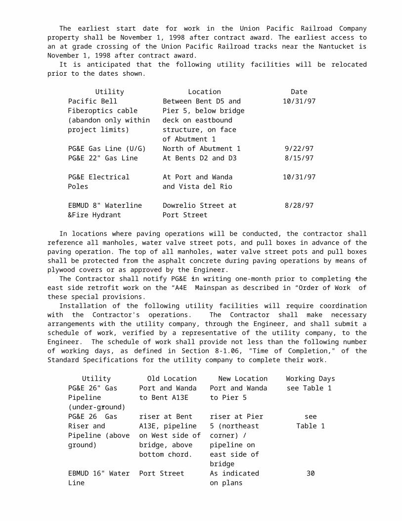
The information to show that the DVBE goal will be met on the "CALTRANS BIDDER - DVBE - INFORMATION" form shall include the names of DVBEs and DVBE joint venture partners to be used, with a complete description of work or supplies to be provided by each and the dollar value of each such DVBE transaction. When 100 percent of a contract item of work is not to be performed or furnished by a DVBE, a description of the exact portion of said work to be performed or furnished by that DVBE shall be included in the DVBE information, including the planned location of said work. DVBE prime contractors shall enter their Office of Small and Minority Business (OSMB) - DVBE reference number and/or DBA name, as listed with OSMB, on the line provided. (Note: DVBE subcontractors to whom the bidder proposes to directly subcontract portions of the work are to be named in the bid. - See Section 2-1.054, "Required Listing of Proposed Subcontractors," of the Standard Specifications and Section 2-1.01, "General," of these special provisions, regarding listing of proposed subcontractors).
If credit for trucking by a DVBE trucking broker is shown on the bidder's information as 100 percent of the revenue to be paid by the broker is to be paid to DVBE truckers, a "certified roster" of the broker's trucks to be used must be included with the bid. The "certified roster" must indicate that all the trucks are owned by certified DVBEs and must show the DVBE truck numbers, owner's name, Public Utilities Commission Cal-T numbers, and the DVBE certification numbers. The roster must indicate that all revenue paid by the broker will be paid to DVBEs listed on the "certified roster".
If credit for trucking by a trucking broker who is not a DVBE is shown in the bidder's information, a "certified roster" of the broker's trucks to be used must be included with the bid. The "certified roster" must indicate that at least 20 percent of the broker's trucks are owned by DVBEs and must show the DVBE truck numbers, owner's name, Public Utilities Commission Cal-T numbers, and the DVBE certification numbers. The roster must indicate that at least 20 percent of the revenue paid by the broker will be paid to DVBEs listed on the "certified roster".
Information necessary to establish the bidder's good faith efforts to meet the DVBE goals shall be included in the "TELEPHONE LOG AND LIST OF REJECTED DVBEs" form located in the Proposal and shall include:
1. The names, dates and times of notices of all certified DVBEs solicited by telephone for this project and the dates, times and methods used for following up initial solicitations to determine with certainty whether the DVBEs were interested.
2. The names of DVBEs who submitted bids which were not accepted and the reason for rejection of the DVBEs bid.
Bidders are cautioned that even though their submittal indicates they will meet the stated DVBE goal, their
submittal should also include the telephone log and rejected DVBE information to protect their eligibility for award of the contract in the event the Department, in its review, finds that the goal has not been met.
It is the bidders responsibility to be available, by phone, both the day of and the day after the bid opening to answer questions and provide good faith effort clarification. The bidder shall also assure that listed DVBEs are available, by phone, on both days.
If it is found that the goal has not been met, the Department will review the information submitted with the bid to determine the bidder’s good faith effort. In the event that the Department determines that a bidder has not made a good faith effort based on the information submitted with the bid and its independent investigation, the Department’s decision will be final.
2-1.05 SMALL BUSINESS PREFERENCEAttention is directed to "Award and Execution of Contract" elsewhere in these special provisions.Attention is also directed to the Small Business Procurement and Contract Act, Government Code Section 14835,
et seq and Title 2, California Code of Regulations, Section 1896, et seq.Bidders who wish to be classified as a Small Business under the provisions of those laws and regulations, shall be
certified as Small Business by the Department of General Services, Office of Small and Minority Business, 1531 "I" Street, Second Floor, Sacramento, CA 95814.
To request Small Business Preference, bidders shall fill out and sign the Request for Small Business Preference form in the Proposal and shall attach a copy of their Office of Small and Minority Business (OSMB) small business certification letter to the form. The bidder's signature on the Request for Small Business Preference certifies, under penalty of perjury, that the bidder is certified as Small Business at the time of bid opening and further certifies, under penalty of perjury, that under the following conditions, at least 50 percent of the subcontractors to be utilized on the project are either certified Small Business or have applied for Small Business certification by bid opening date and are subsequently granted Small Business certification.
CONTRACT NO. 04-043934REVISED PER ADDENDUM NO. 4 DATED MARCH 27, 1998

The conditions requiring the aforementioned 50 percent level of subcontracting by Small Business subcontractors apply if:
1. The lowest responsible bid for the project exceeds $100 000; and 2. The project work to be performed requires a Class A or a Class B contractor's license; and 3. Two or more subcontractors will be used.
If the above conditions apply and Small Business Preference is granted in the award of the contract, the 50 percent Small Business subcontractor utilization level shall be maintained throughout the life of the contract.
2-1.06 CALIFORNIA COMPANY PREFERENCEAttention is directed to "Award and Execution of Contract" of these special provisions.In accordance with the requirements of Section 6107 of the Public Contract Code, a "California company" will be
granted a reciprocal preference for bid comparison purposes as against a nonresident contractor from any state that gives or requires a preference to be given contractors from that state on its public entity construction contracts.
A "California company" means a sole proprietorship, partnership, joint venture, corporation, or other business entity that was a licensed California contractor on the date when bids for the public contract were opened and meets one of the following:
(1) Has its principal place of business in California. (2) Has its principal place of business in a state in which there is no local contractor preference on
construction contracts. (3) Has its principal place of business in a state in which there is a local contractor construction preference
and the contractor has paid not less than $5000 in sales or use taxes to California for construction related activity for each of the five years immediately preceding the submission of the bid.
To carry out the "California company" reciprocal preference requirements of Section 6107 of the Public Contract
Code, all bidders shall fill out and sign the California Company Preference form in the Proposal. The bidder's signature on the California Company Preference form certifies, under penalty of perjury, that the bidder is or is not a "California company" and if not, the amount of the preference applied by the state of the nonresident company.
A nonresident Contractor shall disclose any and all bid preferences provided to the nonresident Contractor by the state or country in which the nonresident Contractor has its principal place of business.
Proposals without the California Company Preference form filled out and signed may be rejected.
2-1.07 BRIDGE SEISMIC RETROFIT INFORMATION/QUESTIONNAIREThe Department has established the need to obtain information regarding each bidder's qualifications for
performing bridge seismic retrofit work contracts.Bidders shall submit responses to the "Bridge Seismic Retrofit Information/Questionnaire" included in the
Proposal. The responses to the Questionnaire shall be submitted with the bid.In signing the signature page of the Proposal, the bidder certifies that the information and answers on the "Bridge
Seismic Retrofit Information/Questionnaire" are complete and accurate.
CONTRACT NO. 04-043934REVISED PER ADDENDUM NO. 4 DATED MARCH 27, 1998

SECTION 3. PRE-AWARD MEETING AND AWARD AND EXECUTION OF CONTRACT
3-1.01 GENERALThe bidder's attention is directed to the provisions in Section 3, "Award and Execution of Contract," of the
Standard Specifications and these special provisions for the requirements and conditions concerning award and execution of contract.
3-1.01A PRE-AWARD MEETING.--Bidders are advised that on May 1, 1998 at 10:00 a.m., in the third
floor conference room, 1727 - 30th Street, Sacramento, CA 95816, the apparent low bidder shall participate in a pre-award qualifications review meeting conducted by an agent of the Director. Non-attendance to the qualifications review meeting by the apparent low bidder shall be just cause for rejection of the bid and forfeiture of the proposal guaranty. At the qualifications review meeting, the low bidder shall be prepared to discuss and answer questions relative to the responses to the "Bridge Seismic Retrofit Information/Questionnaire" submitted with the bid. The Director’s agent will prepare written findings and recommendations to the Engineer regarding award of the contract to the apparent low bidder based on the bridge seismic retrofit information and responses submitted with the bid, and on the information provided at the qualifications review meeting. The Engineer’s determination on the bidder's qualifications for performing bridge seismic retrofit work, in a manner that is safe for the workers and the public, will be based on the bidder's experience, qualifications of on-site supervisory personnel, equipment, conceptual approach to the bridge seismic retrofit work and safety history of the bidder and its supervisory personnel. The decision of the Engineer regarding the bidder's qualifications shall be final.
The second and third apparent low bidders shall participate in pre-award qualifications review meetings if requested to do so by the Department. Notification by the Department will be within 7 days after the bid opening, and will be provided at least 12 hours prior to the qualifications review meeting. Non-attendance by the second or third apparent low bidder at any such requested meeting shall be just cause for rejection of bid and forfeiture of the proposal guaranty.
3-1.01B AWARD AND EXECUTION OF CONTRACT.--The award of contract, if it be awarded, will be to the lowest responsible bidder whose proposal complies with all the requirements prescribed and who has met the goals for DVBE participation or has demonstrated, to the satisfaction of the Department, good faith effort to do so. Meeting the goals for DVBE participation or demonstrating, to the satisfaction of the Department, good faith efforts to do so is a condition for being eligible for award of contract.
It is anticipated that this contract will be awarded within 10 days after the bid opening.Each of the two bonds required in Section 3-1.02, "Contract Bonds," of the Standard Specifications shall be in a
sum equal to 100 percent of the contract price.The contract shall be signed by the successful bidder and shall be received with contract bonds by the Department
within 4 days, including Saturdays, Sundays and legal holidays, after the bidder has received notice that the contract has been awarded. Failure to do so shall be just cause for forfeiture of the proposal guaranty. The executed contract documents shall be delivered to the following address: Department of Transportation, P.O. Box 942874, Sacramento, CA 94274-0001, Attn: Office Engineer (MS 43)- Contracts.
Within 2 days, not including Saturdays, Sundays and legal holidays, of return of the executed contract and bonds, the Department will notify the successful bidder of either approval of the contract by the Attorney General or the attorney appointed and authorized to represent the Department of Transportation, or disapproval of the submittal. Should the Department fail to provide notification within said 2 days, the delay will be considered a right of way delay as specified in Section 8-1.09, "Right of Way Delays," of the Standard Specifications.
A "Vendor Data Record" form will be included in the contract documents to be executed by the successful bidder. The purpose of the form is to facilitate the collection of taxpayer identification data. The form shall be completed and returned to the Department by the successful bidder with the executed contract and contract bonds. For the purposes of the form, vendor shall be deemed to mean the successful bidder. The form is not to be completed for subcontractors or suppliers. Failure to complete and return the "Vendor Data Record" form to the Department as provided herein will result in the retention of 20 percent of payments due the contractor and penalties of up to $20 000. This retention of payments for failure to complete the "Vendor Data Record" form is in addition to any other retention of payments due the Contractor.
CONTRACT NO. 04-043934

REVISED PER ADDENDUM NO. 4 DATED MARCH 27, 1998

Attention is also directed to "Small Business Preference" of these special provisions. Any bidder who is certified as a Small Business by the Department of General Services, Office of Small and Minority Business will be allowed a preference in the award of this contract, if it be awarded, under the following conditions:
(1) The apparent low bidder is not certified as a Small Business, or has not filled out and signed the Request for Small Business Preference included with the bid documents and attached a copy of their Office of Small and Minority Business (OSMB) small business certification letter to the form; and
(2) The bidder filled out and signed the Request for Small Business Preference form included with the bid documents and attached a copy of their Office of Small and Minority Business (OSMB) small business certification letter to the form.
The small business preference will be a reduction in the bid submitted by the small business contractor, for bid comparison purposes, by an amount equal to 5 percent of the amount bid by the apparent low bidder, the amount not to exceed $50 000. If this reduction results in the small business contractor becoming the low bidder, then the contract will be awarded to the small business contractor on the basis of the actual bid of the small business contractor notwithstanding the reduced bid price used for bid comparison purposes.
Attention is also directed to "California Company Preference" of these special provisions.The amount of the California company reciprocal preference shall be equal to the amount of the preference
applied by the state of the nonresident contractor with the lowest responsive bid, except where the "California company" is eligible for a California Small Business Preference, in which case the preference applied shall be the greater of the two, but not both.
If the bidder submitting the lowest responsive bid is not a "California company" and with the benefit of the reciprocal preference, a "California company's" responsive bid is equal to or less than the original lowest responsive bid, the "California company" will be awarded the contract at its submitted bid price except as provided below.
Small business bidders shall have precedence over nonsmall business bidders in that the application of the "California company" preference for which nonsmall business bidders may be eligible shall not result in the denial of the award to a small business bidder.
CONTRACT NO. 04-043934REVISED PER ADDENDUM NO. 4 DATED MARCH 27, 1998

5-1.13 DVBE RECORDSThe Contractor shall maintain records of all subcontracts entered into with certified DVBE subcontractors and
records of materials purchased from certified DVBE suppliers. Such records shall show the name and business address of each DVBE subcontractor or vendor and the total dollar amount actually paid each DVBE subcontractor or vendor.
Upon completion of the contract, a summary of these records shall be prepared on Form CEM-2402 and certified correct by the Contractor or his authorized representative, and shall be furnished to the Engineer.
CONTRACT NO. 04-043934REPLACED PER ADDENDUM NO. 4 DATED MARCH 27, 1998

5-1.14 PERFORMANCE OF DVBE SUBCONTRACTORS AND SUPPLIERSThe DVBEs listed by the Contractor in response to the requirements in Section 2-1.04, "Submission of DVBE
Information," in these special provisions, which are determined by the Department to be certified DVBEs, shall perform the work and supply the materials for which they are listed unless the Contractor has received prior written authorization to perform the work with other forces or to obtain the materials from other sources.
Authorization to utilize other forces or sources of materials may be requested for the following reasons:
(1) The listed DVBE, after having had a reasonable opportunity to do so, fails or refuses to execute a written contract, when such written contract, based upon the general terms, conditions, plans and specifications for the project, or on the terms of such subcontractor's or supplier's written bid, is presented by the Contractor.
(2) The listed DVBE becomes bankrupt or insolvent. (3) The listed DVBE fails or refuses to perform his subcontract or furnish the listed materials. (4) The Contractor stipulated that a bond was a condition of executing a subcontract and the listed DVBE
subcontractor fails or refuses to meet the bond requirements of the Contractor. (5) The work performed by the listed subcontractor is substantially unsatisfactory and is not in substantial
accordance with the plans and specifications, or the subcontractor is substantially delaying or disrupting the progress of the work.
(6) The listed DVBE subcontractor is not licensed pursuant to the Contractors License Law. (7) It would be in the best interest of the State.
The Contractor shall not be entitled to any payment for such work or material unless it is performed or supplied by the listed DVBE or by other forces (including those of the Contractor) pursuant to prior written authorization of the Engineer.
CONTRACT NO. 04-043934REPLACED PER ADDENDUM NO. 4 DATED MARCH 27, 1998

5-1.15 SUBCONTRACTINGAttention is directed to the provisions in Section 8-1.01, "Subcontracting," of the Standard Specifications,
Section 2, "Proposal Requirements and Conditions," Section 2-1.04, "Submission of DVBE Information," and Section 3, "Pre-Award Meeting and Award and Execution of Contract," elsewhere in these special provisions and these special provisions.
The second sentence in the third paragraph of said Section 8-1.01 is amended to read:
When items of work in the Engineer's Estimate are preceded by the letters (S) or (S-F), said items are designated as "Specialty Items."The first sentence in the third paragraph of said Section 8-1.01 is amended to read:
The Contractor shall perform with his own organization contract work amounting to not less than 30 percent of the original total contract price, except that any designated "Specialty Items" may be performed by subcontract and the amount of such "Specialty Items" so performed may be deducted from the original total contract price before computing the amount of work required to be performed by the Contractor with his own organization.
The DVBE information furnished under Section 2-1.04, "Submission of DVBE Information," of these special provisions is in addition to the subcontractor information required to be furnished under said Section 8 -1.01, "Subcontracting," and Section 2-1.054, "Required Listing of Proposed Subcontractors," of the Standard Specifications.
Section 10115 of the Public Contract Code requires the Department to implement provisions to establish a goal for Disabled Veteran Business Enterprise (DVBE) participation in highway contracts that are state funded. As a part of this requirement:
1. No substitution of a DVBE subcontractor shall be made at any time without the written consent of the Department, and
2. If a DVBE subcontractor is unable to perform successfully and is to be replaced, the Contractor will be required to make good faith efforts to replace the original DVBE subcontractor with another DVBE subcontractor.
The requirement in Section 2-1.02, "Disabled Veteran Business Enterprise (DVBE)," of these special provisions that DVBEs must be certified on the date bids are opened does not apply to DVBE substitutions after award of the contract.
CONTRACT NO. 04-043934REVISED PER ADDENDUM NO. 4 DATED MARCH 27, 1998

CALTRANS BIDDER - DVBE - INFORMATION
-- DO NOT DETACH --THIS INFORMATION SHALL BE SUBMITTED WITH
YOUR BID PROPOSALDIST- CO.- RTE.-P.M. : __________________04-CC,Sol-80-12.8/14.1,0.0/0.6
DIST-CONTRACT NO.: ___________________04-043934.
BID AMOUNT $_______________________________________________________________________
BID OPENING DATE:_________________________________________________________________
BIDDER'S NAME
DVBE GOAL FROM CONTRACT:______________________________________________________ %
DVBE PRIME CONTRACTOR INFORMATION *
`
CONTRACT ITEM
NO.
ITEM OF WORK AND DESCRIPTION OR SERVICES TO BE
SUBCONTRACTED OR MATERIALS TO BE
PROVIDED**
FOR CALTRANS
ONLY
NAME OF DVBEs (must be certified on the date bids are opened) (Indicate Second and
Lower Tier Subs)FOR
CALTRANS ONLY
DOLLAR AMOUNT
***DVBE
* DVBE prime contractors shall enter their OSMB -DVBE reference number or their DBA name as listed with OSMB. DVBE prime contractors will have 100 percent DVBE participation and shall not complete the above table.
** If 100% of an item is not performed or furnished by DVBEs, describe the exact portion, including the planned location of work to be performed, of item to be performed or furnished by DVBE.
Total Claimed Participation
$
%
*** Credit for a DVBE supplier, who is not a manufacturer, is limited to 60% of the amount paid to the supplier. Credit for truck brokers may be limited to 20 % of the amount paid for trucking. (See Section 2-1.02 of the Special Provisions.)
IMPORTANT: Names of First Tier DVBE Subcontractors and their respective item(s) of work listed above shall be consistent with the names and items of work in the "List of Sub-contractors" submitted with bid pursuant to the Subcontractors Listing Law and Section 2-1.01, "General," of the Special Provisions. Identify Second and Lower Tier Subcontractors on this form.
Signature of Bidder Date
(Area Code) Telephone Number
Person to Contact (Please Type or Print)
DVBE CT Bidder Information (Rev 09-25-97)
CONTRACT NO. 04-043934REVISED PER ADDENDUM NO. 4 DATED MARCH 27, 1998

Page 2 of 2
- DO NOT DETACH -THIS INFORMATION SHALL BE INCLUDED
WITH YOUR BID PROPOSAL
TELEPHONE LOG AND LIST OF REJECTED DVBEsBidders shall submit the following information to demonstrate that a good faith effort to meet the DVBE goal has
been made if their CALTRANS BIDDER - DVBE - INFORMATION form indicates that the DVBE goal will not be met.
Even if the bidder's CALTRANS BIDDER - DVBE - INFORMATION form indicates the DVBE goal will be met, bidders should submit the following information to protect their eligibility for award of the contract. This is important because the submittal of only the CALTRANS BIDDER - DVBE - INFORMATION form will not normally provide sufficient information to demonstrate that a good faith effort was made. A bidder may not meet the DVBE goal after the submittal is analyzed by Caltrans for various reasons, e.g., if the subcontractor submitted by the bidder was not certified on the date bids were opened, or if the bidder made a mathematical error.
TELEPHONE LOG
The names, dates and times of notices of all certified DVBEs solicited by telephone for this project and the dates, times and methods used for following up initial solicitations to determine with certainty whether the DVBEs were interested:
Names of DVBEs Solicited
Solicitations
Dates and Times
LIST OF REJECTED DVBEs
Names of Rejected DVBEs
Reasons for Rejection of DVBEs:
DVBE Good Faith EffortsInformal Bids Contract (09-29-97) Page 1 of 1
CONTRACT NO. 04-043934REVISED PER ADDENDUM NO. 4 DATED MARCH 27, 1998

STATE OF CALIFORNIA-BUSINESS, TRANSPORTATION AND HOUSING AGENCY PETE WILSON, Governor DEPARTMENT OF TRANSPORTATIONESC/OE MS #43P.O. Box 942874SACRAMENTO, CA 94274-0001
TDD (916) 654-4014
Use Word 6.0c or later to
view Mac intosh pi cture .
April 1, 1998
04-CC,Sol-80-12.8/14.1,0.0/0.604-043934
Addendum No. 5
Dear Contractor:
This addendum is being issued to the contract for construction on State highway in CONTRA COSTA AND SOLANO COUNTIES AT CROCKETT AND IN VALLEJO FROM CUMMINGS SKYWAY OVERCROSSING TO CARQUINEZ BRIDGE TOLL PLAZA..
Submit bids for this work with the understanding and full consideration of this addendum. The revisions declared in this addendum are an essential part of the contract.
Bids for this work will be opened on April 29, 1998.
This addendum is being issued to revise the Project Plans, the Notice to Contractors and Special Provisions, the Engineer's Estimate, and the Proposal and Contract.
Project Plan Sheets 4, 21, 30, 33, 37, 38, 39, 40, 41, 47, 48, 51, 52, 53, 59, 60, 61, 62, 78, 102, 165, 166, 167, 169, 171, 242, 246 and 276 are revised. Half-sized copies of the revised sheets are attached for substitution for the like numbered sheets.
Project Plan Sheets 27B is added. A half-sized copy of the added sheet is attached for addition to the project plans.
On Project Plan Sheet 140 the quantity items listed below are revised as follows:
Core Concrete (3”) And Pressure Grout 360 LF
Core Concrete (4”) & Pressure Grout 3,440 LF
Elastomeric Pad 18 EA
Furnish Structural Steel, Bridge 5,254,000 LB
Erect Structural Steel, Bridge 5,254,000 LB
Miscellaneous Metal, Bridge 110,000 LB
In the Special Provisions, Section 5-1.35, "Drawings", the following item is added to the third paragraph:
"Protective coverings for gas line”

Addendum No. 5 04-CC,Sol-80-12.8/14.1,0.0/0.6Page 2 04-043934April 1, 1998
In the Special Provisions, Section 10-1.01, “Order of Work”, subsection "Approach Span “A4E” and On Ramp “D” Lines:”, the seventh paragraph is revised as follows:
"A 26-inch-diameter gas line will be relocated by others from Span 13 and Bent 13 of Approach A4E to Pier 5 of the A4E Main Spans, and from the west side of the A4E Main Spans to the east side of the A4E Main Spans. Retrofit of Bent 13 and the hinge in Span 13 shall not be initiated, except for minor erection work and preliminary removal, until the gas line has been relocated. Attention is directed to Section 10-1.60, “Steel Structures” of these special provisions."
In the Special Provisions, Section 10-1.01, “Order of Work” subsection “Main Span “A4E”:”, the second paragraph is revised as follows:
"Gas line relocation: The Contractor shall complete all work at the outside face of the east truss before the existing 26-inch-diameter high-pressure gas line is relocated (by others) from the west side of bridge to the east side of bridge, including all work at the bottom chord between panel points L29 to L30, L44 to L45, L71 to L72, and L86 to L87. The gas line shall be relocated (by others) before beginning work on outside face of west truss, except for minor erection and preliminary removal work which may be performed prior to or after relocation. Attention is directed to Section 10-1.60, “Steel Structures” of these special provisions. Also see additional provisions for work on the lower chords. The Contractor shall be responsible for coordinating the gas line relocation(by others) with the construction at Pier 5."
In the Special Provisions, Section 10-1.13, "Obstructions", the tenth paragraph is revised as follows:
"The earliest start date for work in the Union Pacific Railroad Company property shall be November 1, 1998. The earliest access to an at grade crossing of the Union Pacific Railroad tracks near the Nantucket Restaurant is November 1, 1998."
In the Special Provisions, Section 10-1.13, "Obstructions", the seventeenth paragraph is revised as follows:
"No work shall be done at Port Street, at Bents D5, D6, A10E, A11E, and A12E until the new underground gas pipeline has been installed and the old underground gas pipeline deactivated by PG&E. No work other than minor erection or preliminary removal operations shall be done on the west truss of the 1958 bridge, at Bent A13E, or at the west side of the north abutment until the old above- ground gas pipeline has been deactivated by PG&E, nor shall work be done on the east truss, at Pier 5, or at the east side of the north abutment after the new above-ground pipeline has been activated by PG&E without the express written approval of the Engineer."
In the Special Provisions, Section 10-1.17, "Maintaining Traffic" subsection "Liquidated Damages" the first through the fourth paragraphs, inclusive, and subsection "Scheduling Closures" the first through sixth paragraphs, inclusive, are replaced with attached subsections entitled "Notification Of Altered Horizontal And Vertical Clearances" and "Closure Requirements And Conditions".
In the Special Provisions, Section 10-1.41, “Elastomeric Pad” is revised as attached.
In the Special Provisions, Section 10-1.60, “Steel Structures” is revised as attached.
In the Special Provisions, Section 10-1.71, “Shock Transmission Devices” subsection "Section 3 - Execution", the fourth sentence of the first paragraph is revised as follows:
"Three copies of the Qualification Data Package shall be submitted with the Contractor’s bid and seven additional copies shall be submitted upon notification of award of the contract."
In the Special Provisions, Section 10-1.72, "Miscellaneous Metal (Bridge)" is revised as attached.
In the Special Provisions, Section 10-1.72A, "Pipe Support Installation Procedure" is added as attached.

Addendum No. 5 04-CC,Sol-80-12.8/14.1,0.0/0.6Page 3 04-043934April 1, 1998
In the Proposal and Contract, the sheet entitled, "Advanced Processing Of Forms Needed To Approve Contract is revised as attached.
In the "Copy of Engineer's Estimate" in the NOTICE TO CONTRACTORS and the "Engineer's Estimate" in the PROPOSAL, Items 92, 118, 119, 121, 134, 135 and 168 are revised as attached. Item 211 is deleted.
To Proposal and Contract book holders:
REPLACE PAGES 7, 8, 9, AND 11 OF THE ENGINEER'S ESTIMATE IN THE PROPOSAL WITH THE ATTACHED REVISED PAGES 7, 8, 9, AND 11 OF THE ENGINEER'S ESTIMATE. THE REVISED ENGINEER'S ESTIMATE IS TO BE USED IN THE BID SUBMITTAL AND INSERTED IN THE PROPOSAL.
INDICATE RECEIPT OF THIS ADDENDUM BY FILLING IN THE NUMBER OF THIS ADDENDUM IN THE SPACE PROVIDED ON THE SIGNATURE PAGE OF THE PROPOSAL.
Submit bids in the Proposal and Contract book you now possess. Holders who have already mailed their book will be contacted to arrange for the return of their book.
Inform subcontractors and suppliers as necessary.
This office is sending this addendum UPS overnight mail to Proposal and Contract book holders to ensure that each receives it.
If you are not a Proposal and Contract book holder, but request a book to bid on this project, you must comply with the requirements of this letter before submitting your bid.
Sincerely,
ORIGINAL SIGNED BY
NICK YAMBAO, ChiefPlans, Specifications &Estimates BranchOffice of Office Engineer
Attachments

NOTIFICATION OF ALTERED HORIZONTAL AND VERTICAL CLEARANCESThe Contractor shall provide the Engineer with a 21 day written notice prior to making any temporary or
permanent changes at the work site that will affect existing horizontal and vertical clearances on any highway, freeway, ramp, connector, utility or railroad facility. The notice shall be in sufficient detail to show existing and proposed measurements of the alteration and the location where the measurements were taken. Within 24 hours after a change, the Contractor shall provide the Engineer with a written notice indicating the actual horizontal and vertical clearances as changed. The above notification requirements includes the removal of any temporary conditions or restrictions affecting horizontal and vertical clearances.
Temporary changes having an effect on horizontal and vertical clearances include, but are not limited to: installation of falsework, temporary bridges and pedestrian walkways; placement of temporary detours with vertical grade changes and structures, concrete barriers (K-rail, including glare screen if applicable) encroaching on a lane, shoulder, ramp or connector widths; lane shifts or widening; detours, and closure or realignment of ramps.
Permanent clearance alterations include, but are not limited to, pavement overlays under structures, erection of new sign structures or modifications to existing sign structures, seismic retrofit modifications over the traveled way, and construction of new structures.
This requirement is separate and in addition to the requirements of the “Closure Requirements and Conditions” section included in these special provisions. Failure to comply with these requirements will result in disapproved closures and no compensation will be allowed therefore
Compensation for compliance with notification requirements:
Full compensation for conforming to the requirements of this section and its notification requirements is included in the contract prices paid for the various items of work involved and no additional compensation will be allowed therefor.
CLOSURE REQUIREMENTS AND CONDITIONS
Definition of closure. For the purposes and intent of this provision the terms Closure, Lane Closure or pronouns in place of them, shall be interpreted as "encroachment on any portion of the traveled way or shoulder of a highway, freeway, ramp, connector, utility or railroad facility that may affect public traffic."
General. It is the intent of this section “Closure Requirements and Conditions” that the Contractor (a), provide advance closure notification, and (b), not pursue contract work, requiring a closure, outside the time limits specified in section “Lane Requirements and Hours of Work” of these special provisions. All proposed closures will require closure plans subject to submittals and approvals as specified in the “Closure Plans” section of these special provisions. All proposed closures shall be subject to scheduling, notification and approvals on a weekly basis (Monday through Sunday cycle) as specified “Closure Scheduling and Notification” section of these special provisions. The Contractor shall not proceed with work operations requiring a closure without approved closure plans and approved closure schedules in place.
The provisions of this section, “Closure Requirements and Conditions,” will not relieve the Contractor of the responsibility to comply with the provisions in section 7-1.09, “Public Safety,” of the Standard Specifications. Failure to comply with these requirements will result in disapproved closures and no compensation will be allowed therefore.
CLOSURE PLANS
Work Plan. Whenever the Contractor’s operations require any closure, the Contractor shall furnish for the Engineer’s approval, a practicable work plan of the planned operations no later than 14 days prior to the date of the scheduled work. The work plan shall be in sufficient detail to identify all items of work, quantity, sequence, timing of operations and a list of equipment that will be used.
CONTRACT NO. 04-043934REPLACED PER ADDENDUM NO. 5 DATED APRIL 1, 1998

Contingency Plan. In conjunction with the work plan specified above, the Contractor shall provide the Engineer a practicable contingency plan for removing any closure in the event of an equipment breakdown, shortage of or lack of production of materials or any other production failure which would otherwise delay removing the closure within the time limits specified in “Lane Requirements and Hours of Work” included in this section “Maintaining Traffic” or at any time it becomes necessary to provide the lanes, shoulders, ramps, or connectors for use by public traffic due to congested conditions or for any other reason as determined by the Engineer. The contingency plan shall include sufficient detail to identify sequence, timing of operations and a list of equipment that will be used including any standby equipment and stockpiled materials that can be utilized for the immediate removal of closures.
If the Contractor is ordered by the Engineer, in writing, to remove a closure, the Contractor shall immediately commence operations to remove a closure in accordance with the approved contingency plan specified herein.
The Contractor may request, in writing, permission from the Engineer to use a previously approved closure plan when the character and timing of the work contemplated does not vary significantly from the details indicated in the closure plan under consideration. The Engineer shall have the right to withdraw such permission at any time that he determines that the closure plan is impracticable or if the Contractor’s actual operations deviate from the closure plan.
The Contractor shall allow three working days, from the date of submittal, for the Engineer to approve or disapprove any closure plan submitted. Disapproved closure plans will be returned for correction and the Contractor shall allow two working days for the Engineer to review corrected closure plans. Approval of the closure plans by the Engineer shall not relieve the Contractor from the requirement of removing any closure for the safe and efficient operation of public traffic, as specified in “Lane Requirements and Hours of Work” included in this section “Maintaining Traffic.”
Except as provided in the “Aborted Closures” section in these special provisions, full compensation for providing closure plans, correcting the plans, implementing the plans, furnishing, placing and removal of any temporary materials regardless of how many times it is required, shall be considered as included in the contract price paid for the various items of work involved and no additional compensation will be allowed.
CLOSURE SCHEDULING AND NOTIFICATION
Contractor submittals. On or before each Monday at noon, the Contractor shall furnish to the Engineer a written schedule of all closures for the 2 week period beginning the following Monday and ending on a Sunday, 2 weeks later. This schedule will identify: one week in advance, all proposed closures required in the performance of contract work (Week One) and; 2 weeks in advance, all planned closures required in the performance of contract work (Week Two). Closures identified in Week Two of the schedule shall be used for planning purposes and will form the basis for establishing closure entries in Week One of the following week’s submittal.
The written schedule for Week One shall show locations and times when the proposed closures are to be in effect. The Contractor will be provided with copies of "Closure Request Form" (form 4CD-170) for scheduling any closure identified in Week One. Closure requests submitted with incomplete, unintelligible or inaccurate information will be returned for correction. The Contractor will be notified in writing of approval or disapproval of the submitted closure scheduling no later than 3:00 p.m. Thursday of the week preceding the scheduled work. The Contractor will also be notified whenever California Highway Patrol (CHP) assistance is scheduled in conjunction with approved lane closure schedules.
All proposed closures shall conform to the time limits specified in “Lane Requirements and Hours of Work” included in this section “Maintaining Traffic.” Contractor closure schedule requests, without approved closure plans, will not be accepted for consideration of approval by the Engineer.
Changes and Cancellations. Changes, including cancellations, to a previously submitted Week One schedule, proposed by the Contractor, shall be submitted to the Engineer for approval at least 72 hours prior to the time when the closure was to be in place. The written notice to the Engineer of changes to any closure shall be made during normal office hours between the hours of 7:00 a.m. and 3:00 p.m., Monday through Friday, excluding designated legal holidays. The Contractor shall allow a minimum of 24 hours for the Engineer to approve or disapprove the requested changes. A revised request may be submitted for consideration of rescheduling of closures during the week, for work that is postponed due to weather or circumstances, beyond the control of the Contractor, which impacts the previously approved schedule.
Contractor requested changes to the previously approved Week One closure schedule not conforming to the above requirements will be reviewed at the Engineer’s earliest convenience. No compensation will be allowed for disapproved closures due to Contractor initiated changes or cancellations due to weather or circumstances within the control of the Contractor.

CONTRACT NO. 04-043934REPLACED PER ADDENDUM NO. 5 DATED APRIL 1, 1998

Changes and cancellations to the previously submitted Week One schedule or approved closures for which less than 72 hours written notice is provided, will result in an administrative charge to the Contractor of $250.00 per changed or canceled closure, up to a maximum of $1000.00 per day.
For approved closures with work involving California Highway Patrol (CHP) assistance, changes or cancellations with less than 36 hours written notice may result in charges to the Department. In such cases, the Contractor will be charged for all costs resulting from late changes or cancellations. These costs will be a minimum of $50.00 per scheduled CHP officer to a maximum 4 hours of overtime pay per scheduled CHP officer plus vehicle mileage and other costs directly related to the performance of the requested CHP assistance. In no case shall these charges exceed $750.00 per day, per incident.
All monetary charges attributable to changes and cancellations of previously approved closures are cumulative and in addition to any other deductions made under the contract. The Department will deduct these amounts from any moneys due, or that may become due the Contractor under the contract. Cancellations due to weather or circumstances, beyond the control of the Contractor, are exempt from these charges.
Full compensation for conforming to the closure scheduling and notification requirements of this section is included in the contract prices paid for the various items of work involved and no additional compensation will be allowed therefor. Failure to comply with these requirements will result in disapproved closures and no compensation will be allowed therefore.
Invalid Closures. Any closure, which the Engineer has determined not to conform to the provisions of this section, “Closure Requirements and Conditions,” or existing outside the time limits specified in section “Lane Requirements and Hours of Work” of these special provisions shall be considered as an invalid closure. Invalid closures shall be removed immediately from the lanes, shoulders, ramps, or connectors, unless otherwise permitted by the Engineer in writing. Upon failure of the Contractor to comply promptly with the order of the Engineer, the Engineer shall have the authority to cause the removal of the closure and to deduct the cost thereof from any moneys due or to become due the Contractor. The Contractor shall not be entitled to compensation for any impact to his operations in accordance with the “Compensation for Delayed, Disapproved or Aborted Closures” section of these special provisions due to removing an invalid closure.
COMPENSATION FOR DELAYED, DISAPPROVED OR ABORTED CLOSURES
Disapproved closures. Whenever a closure is requested in accordance with the “Closure Scheduling and Notification” section of these special provisions and the Engineer disapproves the closure because it becomes necessary to provide the lanes, shoulders, ramps, or connectors for use by public traffic due to congested conditions or for any other reason, except weather, beyond the control of the Contractor, as determined by the Engineer, the Contractor will be compensated for the cost of the interruption to the Contractor's operations as described below.
Delayed closures. Whenever closure is requested in accordance with the “Closure Scheduling and Notification” section of these special provisions and if there is a delay by the Engineer in approving or disapproving the requested closure, as stated therein, and the Contractor is unable to begin work at the scheduled time, the Contractor will be compensated for the cost of the interruption to the Contractor's operations as described below.
Aborted closures. At any time an approved closure is in place, in accordance with these special provisions, and it becomes necessary to provide the lanes, shoulders, ramps, or connectors for use by public traffic due to congested conditions or for any reason, except weather, beyond the control of the Contractor, as determined by the Engineer, the Contractor will be compensated for the cost of implementing the contingency plan, furnishing, placing and removal of any temporary materials and the cost of interruption to the Contractor's operations as described below:
Compensation for Delayed, Disapproved or Aborted closures will be determined as follows:A. The Contractor will be granted an extension of time commensurate with the delay in accordance with
the provisions of Section 8-1.07, "Liquidated Damages," of the Standard Specifications and the “Progress Schedule (Critical Path)” section of these special provisions.
B. The Contractor will be compensated for the idle time of forces and equipment and any additional costs involved in rescheduling and moving of equipment in accordance with the provisions of Section 8-l.09, "Right of Way Delays," of the Standard Specifications.
CONTRACT NO. 04-043934REPLACED PER ADDENDUM NO. 5 DATED APRIL 1, 1998

DAMAGES
In the event that the Contractor fails to remove the lane, shoulder, ramp or connector closures at the times specified in the "Lane Requirements and Hours of Work" included in this section "Maintaining Traffic," damage will be sustained by the State of California and it is and will be impracticable and extremely difficult to ascertain and determine the actual damage. It is therefore agreed that the Contractor will pay to the State the amounts specified herein as liquidated damages. The liquidated damages herein provided for are in addition to those specified in Standard Specification section 1-1.26, Liquidated Damages.
For each 10 minute period, or fraction thereof, that the lanes, shoulders, ramps or connectors are not available for use by public traffic at the times specified in “Lane Requirements and Hours of Work” included in this section "Maintaining Traffic", the Department will deduct $10,000 up to a maximum of $ 180,000 per day, per incident. These deductions by the Department will be cumulative with each location or operation involved. The Department will deduct those amounts from any moneys due, or that may become due the Contractor under the contract.
Notwithstanding the provisions in the “Damages” section of these special provisions, the Contractor shall not pursue contract work requiring a closure outside the time limits specified in section “Lane Requirements and Hours of Work” of these special provisions. Once the time limits in section “Lane Requirements and Hours of Work” have been exceeded, all rights and permission to occupy the lanes, shoulders, ramps or connectors, previously granted to the Contractor, under the terms of the contract are withdrawn. In such cases, the closure shall be subject to the provisions of the “Invalid Closures” section in these special provisions and the Contractor shall immediately commence operations to remove a closure in accordance with the approved contingency plan specified herein.
Designated legal holidays are: January 1st, the third Monday in February, the last Monday in May, July 4th, the first Monday in September, November 11th, Thanksgiving Day, and December 25th. When a designated legal holiday falls on a Sunday, the following Monday will be a designated legal holiday. When November 11th falls on a Saturday, the preceding Friday shall be a designated legal holiday.
Minor deviations from the requirements of this section concerning hours of work which do not significantly change the cost of the work may be permitted upon the written request of the Contractor if in the opinion of the Engineer, public traffic will be better served and the work expedited. These deviations shall not be adopted by the Contractor until the Engineer has approved them in writing. All other modifications will be made by contract change order.
CONTRACT NO. 04-043934REPLACED PER ADDENDUM NO. 5 DATED APRIL 1, 1998

10-1.41 ELASTOMERIC PADElastomeric pads(20.3 inches thick) on the “A4E” Main Span tower legs, consisting of elastomeric bearing
systems with masonry plates and anchorage components, shall be designed, prototype tested, fabricated, proof tested and constructed as shown on the plans and as provided in these special provisions.
GENERAL.--The Contractor shall furnish, test, and install the number of elastomeric pads shown on the plans. In addition to the elastomeric pads shown on the plans and the prototype test specimens, the Contractor shall furnish two spare elastomeric pads to the State with delivery of the production elastomeric pads, at a location designated by the Engineer.
The elastomeric pads shall consist of alternate layers of rubber and steel plates vulcanized together.The Contractor shall submit complete working drawings for the elastomeric pads to the Office of Structure
Design, Documents Unit, P.O. Box 942874, Sacramento, CA 94274-0001, in accordance with the provisions in Section 5-1.02, “Plans and Working Drawings,” of the Standard Specifications. For initial review, 4 sets of drawings shall be submitted. After initial review, between 6 and 12 sets, as requested by the Engineer shall be submitted to said Office for final approval and use during construction.
Working drawings shall be either 11” x 17” or 22” x 34” in size and each drawing and calculation sheet shall include the State assigned designations for the contract number, bridge number, full name of the structure as shown on the contract plans, District, County, Route, and Post Mile. The design firm’s name, address, and phone number shall be shown on the working drawings. Each sheet shall be numbered in the lower right hand corner and shall contain a blank space in the upper right hand corner for future contract sheet numbers.
The working drawings shall contain all information required for the proper construction of the elastomeric pads, including any required revisions or additions to structural steel, concrete, or reinforcement. The working drawings shall be supplemented with documentation of a quality control program, and with a certified copy of the results of all prototype tests performed on the elastomeric pads and pad materials. Elastomeric pad properties, including compression modulus, shear modulus and vertical compression stiffness shall be furnished on the working drawings. The working drawings shall list the components that will be permanently deformed during prototype or proof testing with calculations showing the anticipated stress in the components at each increment of the vertical force, rotation or shear. Working drawings shall identify temperature requirements for complete vulcanization, including maximum and minimum temperatures and temperature durations. The working drawings shall include a complete description of the bearing test apparatus, including jigs, fixtures, and accessories required to load and to hold the bearings. Each working drawing or calculation sheet shall be signed by an engineer who is registered as a Civil Engineer in the state of California.
The working drawings and supplements for the elastomeric pad shall be submitted in 2 parts. Part 1 shall be completed before fabrication of prototype test specimens. The working drawings and supplements shall be submitted within the following time limits:
ITEMS TIME LIMIT
Part 1: Working drawings, calculations, and quality control program.
Within 8 weeks after contract award.
Part 2: Certified copy of the results of all prototype tests. Sample elastomeric pad from a prototype specimen. Full-sized prototype specimen.
Prior to completion of 25 percent of contract working days, and sufficiently in advance of the start of the work to allow time for review by the Engineer and correction by the Contractor of the working drawings and supplements without delaying the work.
Within 3 weeks after final working drawing approval, one set of the corrected good quality prints on 60 pound
(minimum) bond paper (22” x 34” in size) of all working drawings prepared by the Contractor for the elastomeric pads shall be furnished to the Office of Structure Design, Documents Unit.
The Contractor shall notify the Engineer, in writing, at least 7 days prior to start of elastomeric pad fabrication and testing.
CONTRACT NO. 04-043934REVISED PER ADDENDUM NO. 5 DATED APRIL 1, 1998

ELASTOMERIC PAD DESIGN.-- The elastomeric pads shall be designed for the loading conditions and properties shown on the plans. The elastomeric pad designs shall be confirmed by the certified prototype test results. In addition, if the plans or these special provisions indicate limiting parameters for the elastomeric pad, the pad shall conform to those parameters.
The manufacturer shall certify that the elastomeric pad materials and components will perform their intended function and maintain their design integrity for 40 years from the date of acceptance by the State. The elastomeric pads shall also maintain their design parameters for an ambient temperature range from 30 F to 100 F. Substantiating test data shall be provided to the Engineer.
TEMPERATURE CONTROLS.--Internal temperatures shall be monitored during the vulcanization process. Thermocouples shall be located inside each elastomeric pad at the center of each of the six sides of the pad and in the center of the pad. Continuos time-scaled records shall be made of the temperature readings of each thermocouple. A report shall be prepared and submitted to the Engineer showing the temperature recordings and comparing the recorded temperatures to the target vulcanization temperature shown on the working drawings. Elastomeric pads shall be rejected if any recorded internal temperatures exceed or fall below target vulcanization temperatures.
TESTING.-- A complete series of prototype and proof tests shall be performed in the presence of the Engineer, unless otherwise directed, on full-sized prototype and proof test specimens of the elastomeric pad, as shown on the plans and as specified in these special provisions.
Prototype and proof test specimens of elastomeric pads shall be conditioned for 12 hours at 65 15 F prior to testing, and the ambient temperature shall be maintained at 6515 F during testing.
Prototype and proof tested elastomeric pad test specimens shall be permanently marked on 2 of 4 sides. The markings shall consist of pad type, production lot number, date of fabrication, maximum vertical load, and State assigned contract number.
At the completion of a prototype or proof test, the Contractor shall submit to the Engineer four copies of the complete test results for the elastomeric pads tested. Data for each test shall list key personnel, test loading equipment, identification of elastomeric pad, location of test, and complete record of load, displacement, rotation, and period of load application for each cycle of testing.
PROTOTYPE TESTING.-- A complete series of prototype tests shall be performed in the presence of the Engineer, unless otherwise directed, on at least two full-sized prototype test specimens of the elastomeric pad. Tests shall be conducted in accordance with ASTM Designation D4014, except as noted below. Prototype specimens shall not be used in the finished work. For each cycle of tests, the load, compression displacement and rotation of each prototype specimen shall be recorded.
Prototype Tests 1, 2, and 3 shall be performed on elastomeric pads, as follows:
Prototype Test 1: Each prototype elastomeric pad shall be subjected to a 12-hour sustained vertical load test. The compressive load for the test shall be 2,800,000 pounds. Compressive stiffness shall be recorded at increments of load application and at 2 hour intervals during the sustained load portion of the test.
Prototype Test 2: For each prototype pad three cycles of loading shall be imposed, producing each of the following maximum vertical loads placed eccentrically to induce maximum strains at one side of the pad concurrent with a vertical strain of 0.0 in/in at the opposite side. The elastomeric pads shall be laterally stabilized during testing to prevent lateral displacement, and such lateral bracing shall not inhibit rotation of the pad. The compressive load for the test shall be 2,800,000 pounds.
Prototype Test 3: Each prototype elastomeric pad shall be subject to lateral deformation of 29.0 inches while subject of a constant concentric vertical load of 500,000 pounds. The deformation shall be parallel to the long dimension of the pad.
A complete series of prototype tests shall satisfy the following conditions: Prototype test specimens for Prototype Tests 1, 2, and 3 shall be evaluated in accordance with ASTM D
4014. In the event that delamination occurs between elastomeric layers and the steel plates, or splits or fractures of the elastomer develop, the pad shall be rejected. Evidence of incomplete vulcanization shall be cause for rejection of the pad.
Vertical compression stiffness shall be determined during the prototype tests. The difference between the vertical compression stiffness of the two prototype elastomeric pads shall not exceed 15 percent. The stiffness of the prototype test pads shall not vary by more than 20 percent during the sustained load portion of the test.

CONTRACT NO. 04-043934
REVISED PER ADDENDUM NO. 5 DATED APRIL 1, 1998

Shear stiffness of each pad shall be computed at no fewer than 8 evenly spaced increments of lateral deformation. The difference in shear stiffness of the two pads shall not vary more than 25% at any value of deflection.
After successful prototype testing, one prototype test specimen shall be used by the Contractor to furnish the sample elastomeric pad for testing, unless otherwise directed by the Engineer. One remaining full-sized prototype test specimen shall become property of the State and be furnished, at no cost to the State, to the Transportation Laboratory.
PROOF TESTING.-- Prior to installation of any elastomeric pads, the pads shall be proof tested and evaluated in the presence of the Engineer, unless otherwise directed, as follows:
Proof compression test: Each elastomeric pad shall be loaded for 30 minutes with a concentric vertical load of 2,800,000 pounds.
Proof shear test: Each elastomeric pad shall be subject to a lateral deformation of 14.5 inches while subject to a constant concentric vertical load of 500,000 pounds. The deformation shall be parallel to the long dimension of the pad.
Proof test elastomeric pads shall remain stable without splits, fractures or other unspecified distress at all loading conditions. The compressive stiffness and shear stiffness of each elastomeric pad shall not differ from the median compressive stiffness of all of the elastomeric pads, including the prototype and spare elastomeric pads by more than 15 percent.
MATERIALS.--At the Contractor’s option, steel may conform to the requirements of ASTM Designation: A 570 for steel
laminates.The elastomeric pad systems shall conform to the following requirements: The alternate layers of rubber and steel plates vulcanized together shall conform to the provisions for steel-
laminated elastomeric bearings in ASTM Designation: D 4014, Grade 3, and the following:
ELASTOMER PROPERTIES
PROPERTY ASTM TEST REQUIREMENT
Tensile strength, psi, minimum
D 412
2500
Compression set, 22 hrs. at 158
F, percent, maximum
D 395 (Method B)
25
Tear strength, pounds per inch,
minimum
D 624 (Die C)
180
Shear Modulus, ksi range
D1014 0.11 plus or minus 0.011
Ultimate Elongation at
break, percent, minimum
D412
600
Ozone resistance, 20%
strain, 100 hours at 104 ˚F plus or minus 3.6 ˚F
D1149 (except 100 plus or minus 2 parts per 100,000,000)
No Cracks

CONTRACT NO. 04-043934REVISED PER ADDENDUM NO. 5 DATED APRIL 1, 1998

The elastomer in the elastomeric pads shall be natural rubber, Type NR, or at the Contractor’s option, natural rubber prepared from butadiene (BR-NR).
The thickness for steel laminates shall be 0.20 inch. Galvanizing of steel laminates will not be required. Steel laminates shall not have holes.
The steel laminates shall be covered at the sides of the elastomeric pads with a minimum thickness of 1/2 inch of the same elastomer as specified for the elastomeric pad. At the Contractor’s option, ethylene propylene rubber (EPDM), with a minimum thickness of 5/16 inch and ozone resistance equal to that specified for the elastomer in the pad, may be used as an elastomer cover.
Stacking of individually laminated pads or cold bonding of individual laminated pads will not be permitted. Two sample of elastomeric pad from a pad used for the prototype tests, 2.250.125 inches high and not less
than 8 inches by 12 inches in plan taken from the center and outside corner of the pad, shall be furnished to the Engineer and shall supplement the working drawings. The Contractor shall allow 3 weeks for testing and obtaining satisfactory results after sample elastomeric pads have been received.
A test specimen taken from the sample furnished to the Engineer will be tested in accordance with California Test 663 for 10,000 cycles at the design load and 1/2 T (T = total thickness of elastomer) translation. The testing speed shall not exceed 4 1/2 inches per minute. Specimens tested shall show no indication of deterioration of elastomer or loss of bond between elastomer and steel laminates, or permanent deformation or surface cracks that are wider or deeper than 2/3 of the rubber cover thickness..
The manufacturer shall provide the Engineer with a Certificate of Compliance in accordance with the provisions of Section 6-1.07, “Certificates of Compliance,” of the Standard Specifications. These certificates shall certify that the elastomeric pads conform to the design and material requirements, and were manufactured in accordance with the approved quality control program. The certification shall be supported by a copy of the results of tests performed on the elastomeric pad
Test results shall be certified correct and signed by the testing laboratory personnel who conducted the test and interpreted the test results.
Elastomeric pads will be measured and paid for by the unit as elastomeric pad. The quantity of elastomeric pads will be determined from actual count of the elastomeric pads in place in the completed work.
The spare elastomeric pads will be measured and paid for as elastomeric pad.The contract unit prices paid for elastomeric pad shall include full compensation for furnishing all labor, materials
(including sample pads used for testing), tools, equipment and incidentals, and for doing all the work involved in designing, prototype and proof testing, fabricating, constructing and installing the elastomeric pads) on the “A4E” Main Span tower legs, complete in place, as shown on the plans, as specified in the Standard Specifications and these special provisions, and as directed by the Engineer.
If a portion or all of the elastomeric pads are tested at a site more than 300 airline miles from both Sacramento and Los Angeles, additional shop inspection expenses will be sustained by the State. Payment to the Contractor for elastomeric pad will be reduced $5,000 for each testing site located more than 300 airline miles from both Sacramento and Los Angeles, or in the case of each testing site located more than 3,000 airline miles from both Sacramento and Los Angeles, payment will be reduced $8,000.
CONTRACT NO. 04-043934REVISED PER ADDENDUM NO. 5 DATED APRIL 1, 1998

10-1.60 STEEL STRUCTURESConstruction of steel structures shall conform to the provisions in Section 55, "Steel Structures," of the Standard
Specifications and these special provisions.Attention is directed to “Field Welding Quality Control” elsewhere in these special provisions. GENERAL.-- Attention is directed to the provisions in "Order of Work," "Maintaining Traffic," "Clean and Paint
Structural Steel," "Raise Bridge," "Temporary Supports," "Equipment Loading on Bridges" and "Bolt or Rivet Removal and Replacement" of these special provisions.
Steel structures to be constructed on this project involve retrofitting and modifying portions of the existing steel structure. The Contractor shall prepare detailed dimensional verification of the as-built condition of the existing structure and its components. Working drawings for structural steel shall be prepared from the actual surveyed conditions. Bridge removal of the steel components shall not begin until the complete survey is completed and working drawings are submitted to the Engineer in conformance with the provisions of Section 55-1.02, "Drawings," of the Standard Specification and these special provisions.
The Contractor shall notify the Engineer upon discovery of discrepancies in the field conditions that could require modification of the designs as shown on the plans.
The first paragraph in Section 55-1.02, "Drawings," of the Standard Specifications is amended to read:
The Contractor shall submit working drawings for structural steel to the Office of Structure Design, Documents Unit, P.O. Box 942874, Mail Stop 9, Sacramento, California 94274-0001 (1801 30th Street, Sacramento, CA 95816), telephone (916) 227-8230, for approval in accordance with the provisions in Section 5-1.02, “Plans and Working Drawings”. For initial review, 6 sets of the drawings shall be submitted for highway bridges and 10 sets shall be submitted for railroad bridges. After review, between 6 and 12 sets, as requested by the Engineer, shall be submitted to the Office for final approval and for use during construction.
The seventh paragraph in Section 55-1.02, "Drawings," of the Standard Specifications is amended to read:
At the completion of each structure on the contract, one set of reduced prints on 20 pound (minimum) bond paper, 11 inches by 17 inches in size, of the corrected original tracings of all working drawings for each structure shall be furnished to the Engineer. Reduced prints that are common to more than one structure shall be submitted for each structure. An index prepared specifically for the drawings for each structure containing sheet numbers and titles shall be included on the first reduced print in the set for each structure. Reduced prints for each structure shall be arranged in the order of drawing numbers shown in the index.
The eighth paragraph in Section 55-1.02, "Drawings," of the Standard Specifications is amended to read:
The edge of the corrected original tracing image shall be clearly visible and visually parallel with the edges of the page. A clear, legible symbol shall be provided on the upper left side of each page to show the amount of reduction and a horizontal and vertical scale shall be provided on each reduced print to facilitate enlargement to original scale.
The first paragraph in Section 55-3.14A(1), "Punching," of the Standard Specifications is amended to read:
Punching or sub-punching of high-strength structural steel where the material is thicker than 3/4 inch will not be permitted for material less than 50ksi. Punching or sub-punching of high-strength structural steel where the material is thicker than 5/8 inch will not be permitted for material greater than or equal to 50ksi.
Additional certified test reports for fastener assemblies will be required as specified in "Fabrication" of this specification.
Fabricators of structural steel shall be certified under the AISC Quality Certification Program, Category III, Major Steel Bridges.
Steel for members, shown on the plans as fracture critical members, shall conform to the requirements of ANSI/AASHTO/AWS D1.5, Section 12, "AASHTO/AWS Fracture Control Plan (FCP) for Non-Redundant Members."
CONTRACT NO. 04-043934

REVISED PER ADDENDUM NO. 5 DATED APRIL 1, 1998

FIELD MEASUREMENTS.--The Contractor shall verify all dimensions required for attachment of new work to the existing structure and shall secure all field measurements required for proper and adequate fabrication and installation of the work. Exact measurements are the Contractor's responsibility and the Contractor shall be solely responsible for the correct fit of all new construction. Copies of all field measurements shall be furnished to the Engineer.
The dimensions of the existing structure shown on the plans are based on the original contract plans and working details and may not accurately represent the actual dimensions of the structure. The Contractor shall verify in the field the accuracy of the information shown on the plans as needed for proper and adequate fabrication and installation of the work.
The Contractor shall, at his expense, make the necessary changes in dimensions of the work to meet existing conditions.
Where necessary to verify accuracy of dimensions, the Contractor may remove a maximum of two but not more than one-half the number of existing rivets or bolts in any connection and replace such rivets or bolts with high-strength bolts. Where such a location is designated for rivet or bolt removal and replacement with a permanent high-strength bolt on the plans, removal and replacement shall be in accordance with "Bolt or Rivet Removal and Replacement " elsewhere in these special provisions.
Where gusset plates are shown on the plans to be replaced with new gusset plates, the old plate shall be used as a template to field punch or drill the new plate to assure correct bolt alignment.
INSPECTION.--The first sentence of the first paragraph in Section 55-1.03, "Inspection," of the Standard Specifications is amended to read:
Structural steel will be inspected at the fabrication site except as provided in "Check Testing" of the special provisions.
STRUCTURAL STEEL MATERIALS.--The first paragraph, including the material table, in Section 55-2.01, "Description," of the Standard Specifications is amended to read:
55-2.01 Description.--The various materials shall conform to the specifications of ASTM as listed in the following tabulation with certain modifications and additions as specified:
MATERIAL SPECIFICATION
Structural steel ASTM Designation: A 709/A 709M, Grade 36 [250] or A 36/A 36M(a)
High strength low alloy columbium vanadium steel
ASTM Designation: A 709/A 709M, Grade 50 [345] or A 572/A 572M, Grade 50 [345](a)
High strength low alloy structural steel ASTM Designation: A 709/A 709M, Grade 50W [345 W] or A 588/A 588M(a)
Quenched and tempered low alloy steel ASTM Designation: A 709/A 709M, Grade 70WHigh-yield strength, quenched and tempered alloy
steel plate suitable for welding ASTM Designation: A 709/A 709M,
Grade 100 [690] and Grade 100W [690W] or A 514/A 514M(a)
Steel fasteners for general applications:
Bolts and studs which include threaded rods and nonheaded anchor bolts
Nuts
Washers
ASTM Designation: A 307 galvanized orAASHTO Designation:
M 314, Grade 36 or 55, galvanized
ASTM Designation: A 563 including Appendix X1, galvanized(b,c)
ASTM Designation: F 844, galvanized
High strength steel fasteners:
Bolts for structural steel jointsASTM Designation: A 325 or
A 325M, galvanized
Bolts and studs which include threaded rods and nonheaded anchor bolts, for general applications
Upset Rods
Nuts
Washers
ASTM Designation: A 449, galvanized
ASTM Designation A 588
ASTM Designation: A 563 including Appendix X1(b) orA 563M including Appendix X1(b,c)
ASTM Designation: F 436 orF 436M
Carbon steel for forgings, pins and rollers ASTM Designation: A 668/A 668M, Class D
Alloy steel for forgings ASTM Designation: A 668/A 668M, Class F for pins less than 10” in dia, Class G for pins less than 20” in dia
Pin nuts ASTM Designation: A 36/A 36MCarbon-steel castings ASTM Designation: A 27/A 27M, Grade 65-35
[450-240], Class 1Malleable iron castings ASTM Designation: A 47, Grade 32510 or
A 47M, Grade 22010Gray iron castings ASTM Designation: A 48, Class 30BCarbon steel structural tubing ASTM Designation: A 500, Grade B or A 501
Steel pipe (Hydrostatic testing will not apply) ASTM Designation: A 53, Type E or S, Grade B;A 106, Grade B; or A 139, Grade B
Stud connectors ASTM Designation: A 108 andANSI/AASHTO/AWS D1.5
(a) Grades that may be substituted for the equivalent ASTM Designation: A 709 steel, at the Contractor's option, subject to the modifications and additions specified and to the requirements of A 709.
(b) Nuts made and marked in accordance with the requirements of ASTM Designation: A 194/A 194M, Grade 2H are an acceptable substitution for heavy hex nuts complying with ASTM Designation: A 563, Grade DH. This substitution is permitted, provided that the zinc coating, overtapping, lubrication, rotational capacity requirements and testing of the substituted nuts meet the same requirements as specified for the A 563 nuts, including all supplementary requirements. Proof load testing and stresses required for ASTM A 194 zinc-coated nuts shall be the same as required for ASTM A 194 plain uncoated nuts.
(c) All zinc-coated nuts that will be tightened beyond snug or wrench tight shall be furnished with a dry lubricant conforming to Supplementary Requirement S2 in ASTM Designation: A 563.
CONTRACT NO. 04-043934REVISED PER ADDENDUM NO. 5 DATED APRIL 1, 1998

The second paragraph in Section 55-2.01, "Description," of the Standard Specifications is deleted.The fifth paragraph in Section 55-2.01, "Description," of the Standard Specifications is amended to read:
All structural steel plate used for the fabrication of tension members, tension flanges, eyebars and hanger plates and for splice plates of tension members, tension flanges and eyebars shall meet the longitudinal Charpy V-notch impact value requirements specified herein. Sampling procedures shall conform to the provisions in ASTM Designation: A 673/A 673M. The H (Heat) frequency of testing shall be used for structural steels conforming to ASTM Designations: A 709/A 709M, Grades 36, 50 and 50W. The P (Piece) frequency of testing shall be used for structural steel conforming to ASTM Designation: A 709/A 709M, Grades 70W, 100 and 100W. Charpy V-notch impact values shall be determined in accordance with ASTM Designation: E 23.
The last paragraph in Section 55-2.01, "Description," of the Standard Specifications is amended to include:
AASHTO M270, A 207, Grade 70W.............................................30 at -20°F AASHTO M270, A 207, Grade 100, 2 1/2” thick and less.......................35 at 0°F AASHTO M270 ,A 207, Grade 100, greater than 2 1/2” thick..................45 at 0°F
The first paragraph in Section 55-2.02, "Structural Steel," of the Standard Specifications is amended to read:
55-2.02 Structural Steel.--Unless otherwise specified or shown on the plans, all structural steel plates, shapes and bars shall conform to ASTM Designation: A 709/A 709M, Grade 50 .
The first paragraph in Section 55-2.07, "Unidentified Stock Material," of the Standard Specifications is amended
to read:
Unidentified stock material consisting of material Grade50 or lower only, which cannot be identified with certified mill test reports, may be used on non fracture critical members subject to the requirements of this section.
Structural steel rolled shapes used in shear locks shall conform to the Charpy V-notch impact values of 30 ft-lbs at
30 °F .High-strength structural steel bolts, or equivalent fasteners, and other bolts attached to structural steel, with nuts
and washers shall be galvanized. Tension control bolt assemblies shall be zinc-coated by the mechanically deposited process.
CHECK TESTING.--Structural steel shall conform to the designated ASTM Standard and the check testing requirements of this section.
Check samples shall be furnished for each heat of maximum thickness of:
Flanges and webs of fracture critical members.
Steel plates, shapes or bars containing check samples shall be furnished from the mill with extra length in order to provide for removal of material for check samples at the point of fabrication. Check samples may be cut from either end of the designated plate, shape or bar.
At the option of the Contractor, check samples may be removed at the rolling mill rather than at the point of fabrication. The sample will be removed from the mill plate that will be stripped by the fabricator to produce the designated plate and may be taken from any location within that plate. The mill plate from which samples are removed shall be marked with the same identifying numbers as are used on the samples. If the Contractor requests that samples be removed at the rolling mill, the Contractor will be charged for the cost of providing State inspection at the mill to witness the removal of samples, as provided in Measurement and Payment of these special provisions.
Unless otherwise directed, material for check samples shall be removed by the Contractor in the presence of the Engineer. Check samples for plates wider than 24 inches shall be 14 inches wide and 18 inches long with the long dimension transverse to the direction of rolling. Check samples for all other products shall be 18 inches long, taken in the direction of rolling, and the width shall be the product width. Check samples shall be removed and delivered to the Engineer before the material is fabricated into components and preferably when it is still being prepared for fabrication. The direction of rolling, heat numbers, and plate numbers shall be marked on the samples with paint or other indelible marking material or may be steel stamped in one corner of the plate.

CONTRACT NO. 04-043934REVISED PER ADDENDUM NO. 5 DATED APRIL 1, 1998

Unless otherwise directed, check samples shall be delivered to the Transportation Laboratory at the Contractor's expense. The check samples will be tested by the Transportation Laboratory for compliance with the requirements specified in ASTM and these special provisions. Check sample test results will be reported to the Contractor within 10 working days of delivery to the Transportation Laboratory. In the event several samples are submitted on the same day, an additional day will be added for each 2 samples submitted. The test report will be made for the group of samples.
The results of the tensile and impact tests shall not vary more than 5 percent below specified minimum or 5 percent above specified maximum requirements except that if the initial check test results vary more than 5 percent but not more than 10 percent from the specified requirements, a re-test may be performed on another sample from the same heat and thickness. The results of the re-test shall not vary more than 5 percent from the original specified requirements. If the results of check tests exceed these permissible variations, all material planned for use from the heat represented by said check samples shall be subject to rejection.
FABRICATION.-- The first paragraph in Section 55-3.14, "Bolted Connections," of the Standard Specifications shall be amended to include the following sentence:
High-strength bolts shall have threads excluded from connection shear planes.
The first paragraph of Section 55-3.05, "Facing and Bearing Surfaces," of the Standard Specifications is amended to read:
55-3.05 Faying and Bearing Surfaces.—Surfaces of bearing and base plates and other metal bearing surfaces that are to come in contact with each other or with ground concrete surfaces or with asbestos sheet packing shall be flat to within 1/32 inch tolerance in 12 inches and to within 1/16 inch tolerance overall. Surfaces of bearing and base plates and other metal bearing surfaces that are to come in contact with preformed fabric pads, elastomeric bearing pads or portland cement mortar shall be flat to within 1/8 inch tolerance in 12 inches and to within 3/16 inch tolerance overall.
Paragraphs 1 through 5 of Section 55-3.14, "Bolted Connections," of the Standard Specifications are amended to read:
55-3.14 Bolted Connections.—Bolted connections, unless otherwise shown on the plans or specified in the special provisions, shall be made with high-strength steel fastener assemblies. Fastener assemblies for high-strength connections shall be either 1) a high-strength steel bolt, nut and washer assembly or, 2) a tension control bolt assembly.When threaded studs are shown on the plans to be used in high-strength fastener assemblies, these assemblies shall conform to the requirements specified herein for high-strength fastener assemblies.
Bolted connections using high-strength fastener assemblies shall conform to the "Specification for Structural Joints Using ASTM A 325 or A 490 Bolts," approved by the Research Council on Structural Connections of the Engineering Foundation (RCSC Specification), and the requirements of these special provisions.
When reference is made to the RCSC Specification, the "Allowable Stress Design" version shall be used when allowable stress design is shown on the plans and the "Load and Resistance Factor Design" version shall be used when load and resistance factor design is shown on the plans.
All connections made with high-strength fastener assemblies shall be tensioned and inspected after tensioning, whether classified as a slip critical or bearing type connection, unless otherwise designated on the plans.
All high-strength bolts shall be installed with a hardened washer under the nut or bolt head, whichever is the element turned in tightening. Nuts shall be located, wherever practicable, on the side of the member that will not be visible from the traveled way. Nuts for bolts that will be partially embedded in concrete shall be located on the side of the member that will be encased in concrete.
All fastener assemblies used in any one joint of a high-strength bolted connection shall be from the same rotational capacity lot.
The Contractor shall provide, calibrate and maintain all equipment and tools necessary for the preliminary testing, installation and inspection of all fasteners.
Bolt tension measuring devices and torque wrenches shall be calibrated within one year prior to first being used on the job, and a minimum of once each year thereafter. This calibration shall be done by a qualified independent laboratory or authorized warranty repair and calibration center recognized by the tool manufacturer. Bolt tension measuring devices shall be calibrated, to within one percent of the actual tension value, with a minimum of 4 verification readings evenly spaced over a range of 20 to 80 percent of full scale. All torque wrenches shall have either a dial gage or digital read-out. Torque wrenches shall be calibrated, to within 2 percent of the actual torque value, with a minimum of 4 verification readings evenly spaced over a range of 20 to 100 percent of full scale. All test equipment used for certification and calibration standards shall be traceable to the National Institute of Standards and Technology.

CONTRACT NO. 04-043934REVISED PER ADDENDUM NO. 5 DATED APRIL 1, 1998
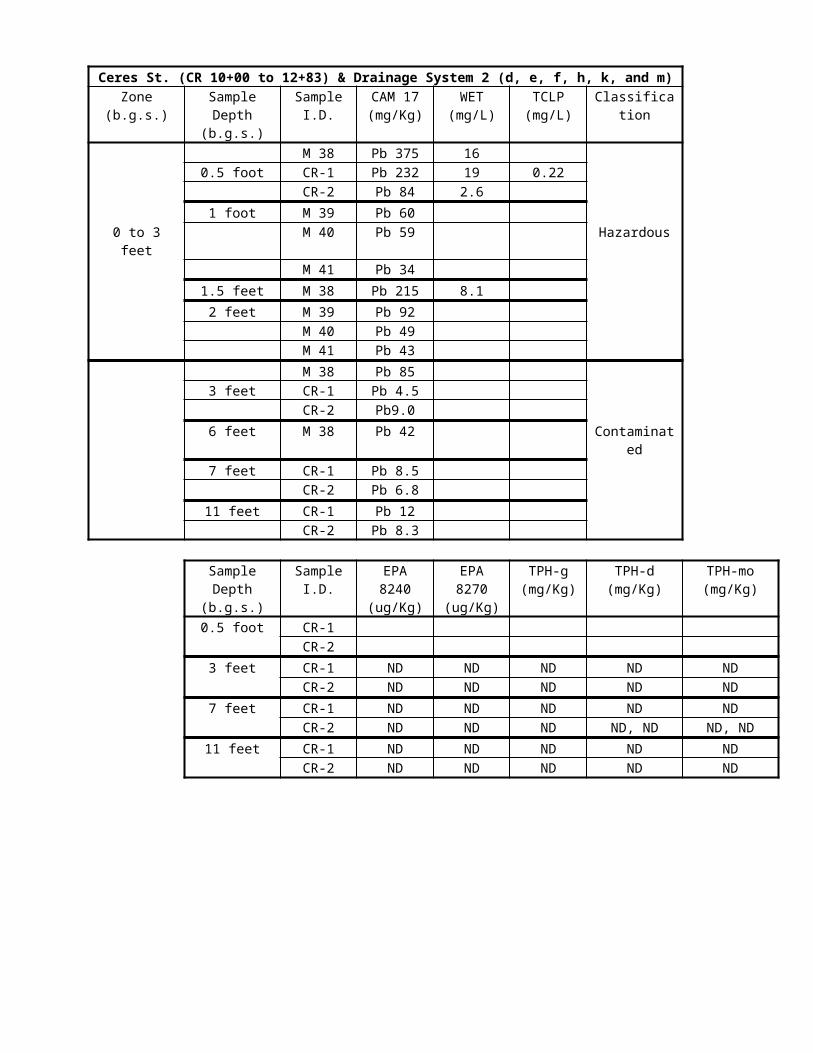
Prior to the use of bolt tension measuring devices or torque wrenches, the Contractor shall furnish to the Engineer certificates of calibration with plots of verification readings for each device or wrench.
In addition to the submittals required in Section 55-1.03, "Inspection," of the Standard Specifications, the Contractor shall furnish certified test reports of tests on fastener components and fastener assemblies performed prior to shipment to the job-site. Certified test reports for fastener components and fastener assemblies shall be furnished to the Engineer prior to use of the fastener assembly. The certified test reports shall include the rotational capacity lot numbers for fastener assemblies supplied and test reports specified in the "Certification," "Report," "Number of Tests and Retests," and "Certification and Test Report" sections in the appropriate ASTM specifications for the fastener components. In addition, certified test reports as specified in the "Certification and Test Report" section of ASTM Designation: A 325 shall be provided for any type of bolt used in a fastener assembly.
Section 55-3.14, "Bolted Connections," of the Standard Specifications is amended by adding the following
paragraphs:
55-3.14B Surface Preparation.—Contact surfaces of all high-strength bolted connections shall be cleaned and coated before assembly in accordance with the provisions for cleaning and painting structural steel in the special provisions.
55-3.14C Installation.—If water soluble lubricants are used on nuts, fastener installation will not be
permitted when surface moisture is present at any high-strength bolted connection. The Engineer may require the Contractor to perform additional installation tension tests before fastener installation and tensioning is performed at any high-strength bolted connection during inclement weather.
Bolts shall be tightened to the required tension by use of a calibrated power wrench, a calibrated manual torque wrench, or by the turn-of-nut method.The threaded ends of fastener assemblies, where first full formed threads are present, shall be at least flush with, but not extend more than 1/4-inch beyond, the outer face of the nut. A maximum of one additional hardened washer may be installed under the non-turning element of the fastener assembly. The threaded ends of studs, rods and anchor bolts, shall extend at least 1/8-inch beyond the outer face of the nut.
Larger bolts, having diameters up to 1/4-inch greater than the diameter of the bolt shown on the plans, may be used if approved by the Engineer provided that spacing and edge distance requirements for the larger bolt are met and the net section is adequate.
Tension control bolts shall have a splined end extending beyond the threaded portion of the bolt that shears off after the specified minimum bolt tension has been attained. During installation, the torque required to turn the nut on the tension control bolt shall be counterbalanced by the torsion shear resistance of the splined end of the bolt. The same type of bolt head and head orientation shall be used within any one high-strength bolted connection.
55-3.14D Rotational Capacity Testing Prior to Shipment to Job Site.—Rotational capacity tests shall be
performed on all fastener assemblies prior to shipment to the job-site. Galvanized assemblies shall be tested as galvanized. One washer shall be used under each nut for all tests.
Each combination of bolt production lot, nut lot and washer lot shall be tested as an assembly. A rotational capacity lot number shall be assigned to each combination of lots tested. Each shipping unit of
fastener assemblies shall be plainly marked with the rotational capacity lot number. Two fastener assemblies from each rotational capacity lot shall be tested. The following equipment, procedure and acceptance criteria shall be used to perform rotational capacity
tests on, and determine acceptance of long bolts. Long bolts are fasteners that can achieve full nut thread engagement when installed in a bolt tension measuring device.
Long Bolt Test Equipment:
1. Calibrated bolt tension measuring device with adequate tension capacity for the bolts being tested.2. Calibrated dial or digital torque wrench. A torque multiplier may be required for large diameter
bolts.3. Washers having an inside diameter no more than 1/16 inch greater than the nominal diameter of the
bolt to be tested. Spacers with the same inside diameter and equal or larger outside diameter as the washers may also be required.
4. Steel beam or member, such as a girder flange or cross frame, to which the bolt tension measuring device will be attached. The device must be accessible from the ground.

CONTRACT NO. 04-043934REVISED PER ADDENDUM NO. 5 DATED APRIL 1, 1998

Long Bolt Test Procedure:
1. Measure the bolt length. The bolt length is the distance from the end of the threaded portion of the shank to the underside of the bolt head.
2. Install the nut on the bolt so that 3 to 5 full threads of the bolt are located between the bearing face of the nut and the underside of the bolt head. Measure and record the thread stickout of the bolt. Thread stickout is determined by measuring the distance from the outer face of the nut to the end of the threaded portion of the shank.
3. Insert the bolt into the bolt tension measuring device and install the required number of washers, and any additional spacers as needed, directly beneath the nut to produce the thread stickout measured in Step 2.
4. Tighten the nut using a hand wrench to a snug-tight condition. The snug tension shall not be less than the Table A value but may exceed the Table A value by a maximum of 2 kips.
Table AFastener Assembly Tension Values to Approximate Snug-Tight Condition
Bolt Diameter(inch)
Snug Tension(kips)
1/2 15/8 23/4 37/8 41 5
1 1/8 61 1/4 71 3/8 91 1/2 10
5. Match-mark the assembly by placing aligning marks on one corner of the nut, across the flat on the end of the bolt, and a heavy reference line on the face plate of the bolt tension measuring device. Place an additional mark on the outside of the socket that lines up with the mark on the nut corner so that it is visible while turning the nut. Make an additional small mark on the face plate, either 2/3 of a turn, one turn, or 1 1/3 turn clockwise from the heavy reference line, depending on the bolt length being tested as shown in Table B.
Table BRequired Nut Rotation for Rotational Capacity
Tests(a,b)Bolt Length (measured
in Step 1)Required Rotation
(turn)4 bolt diameters or less 2/3
Greater than 4 bolt diameters but no more than 8 bolt diameters
1
Greater than 8 bolt diameters(c)
1 1/3
(a) Nut rotation is relative to bolt, regardless of the element (nut or bolt) being turned. For bolts installed by 1/2 turn and less, the tolerance shall be plus or minus 30 degrees; for bolts installed by 2/3 turn and more, the tolerance shall be plus or minus 45 degrees.
(b) Applicable only to connections in which all material within grip of the bolt is steel.
(c) When bolt lengths exceed 12 diameters, the required rotation must be determined by actual tests in a suitable tension device simulating the actual conditions.
CONTRACT NO. 04-043934REVISED PER ADDENDUM NO. 5 DATED APRIL 1, 1998

6. Tension the bolt by turning the nut to achieve the applicable minimum tension value listed in Table C. After reaching this tension, record the moving torque, in foot-pounds, required to turn the nut, and also record the corresponding bolt tension value in pounds. Torque must be measured with the nut in motion. Calculate the value, T, T=[(the measured tension in pounds) x (the bolt diameter in inches) / 48].
Table CMinimum Tension Values for Fastener Assemblies
Bolt Diameter(inch)
Minimum Tension(kips)
1/2 125/8 193/4 287/8 391 51
1 1/8 561 1/4 711 3/8 851 1/2 103
7. Tension the nut further until the rotation listed in Table B is reached. The rotation is measured from the heavy reference line made on the face plate after the bolt was snug-tight. Record this bolt tension.
8. Loosen and remove the nut and examine the threads on both the nut and bolt.
Long Bolt Acceptance Criteria:
An assembly must pass all of the following requirements to be acceptable: 1) the measured moving torque (Step 6) must be less than or equal to the calculated torque value, T (Step 6), 2) the bolt tension measured in Step 7 must be greater than or equal to the applicable turn test tension value listed in Table D, 3) the nut must be able to be removed from the bolt without signs of thread stripping or galling after the required rotation in Step 7 has been achieved, 4) the bolt does not shear from torsion or fail during the test and 5) the assembly does not seize before the final rotation in Step 7 is reached. Elongation of the bolt in the threaded region between the bearing face of the nut and the underside of the bolt head will not be considered a failure. Both assemblies tested from one rotational capacity lot must pass for the rotational capacity lot to be acceptable.
Table DTurn Test Tension Values
Bolt Diameter(inch)
Turn Test Tension(kips)
1/2 145/8 223/4 327/8 451 59
1 1/8 641 1/4 821 3/8 981 1/2 118
The following equipment, procedure and acceptance criteria shall be used to perform rotational capacity tests on and determine acceptance of short bolts. Short bolts are fasteners that cannot achieve full nut thread engagement when installed in a bolt tension measuring device.
CONTRACT NO. 04-043934REVISED PER ADDENDUM NO. 5 DATED APRIL 1, 1998

Short Bolt Test Equipment:
1. Calibrated dial or digital torque wrench. A torque multiplier may be required for large diameter bolts.
2. Spud wrench or equivalent.3. Washers having an inside diameter no more than 1/16 inch greater than the nominal diameter of the
bolt to be tested. Spacers with the same inside diameter and equal or larger outside diameter as the washers may also be required.
4. Steel plate or girder with a hole to install bolt. The hole size shall be 1/16 inch greater than the nominal diameter of the bolt to be tested. Any girder having an appropriately sized bolt hole and plate thickness with washers, and any additional spacers as needed, which will provide the proper number of threads within the grip, as required in Step 2 below, may be used.
Short Bolt Test Procedure:
1. Measure the bolt length. The bolt length is the distance from the end of the threaded portion of the shank to the underside of the bolt head.
2. Install the nut on the bolt so that 3 to 5 full threads of the bolt are located between the bearing face of the nut and the underside of the bolt head. Measure and record the thread stickout of the bolt. Thread stickout is determined by measuring the distance from the outer face of the nut to the end of the threaded portion of the shank.
3. Install the bolt into a hole on the plate or girder and install the required number of washers, and any additional spacers as needed, between the bearing face of the nut and the underside of the bolt head to produce the thread stickout measured in Step 2.
4. Tighten the nut using a hand wrench to a snug-tight condition. The snug condition shall be the full manual effort applied to the end of a 12-inch long wrench. This applied torque shall not exceed 20% of the maximum allowable torque in Table E.
Table EMaximum Allowable Torque for Fastener
AssembliesBolt Diameter
(inch)Torque (ft-lbs)
1/2 1455/8 2853/4 5007/8 8201 1220
1 1/8 15001 1/4 21301 3/8 28001 1/2 3700
5. Match-mark the assembly by placing aligning marks on one corner of the nut, across the flat on the end of the bolt, and a heavy reference line on the steel plate or girder. Place an additional mark on the outside of the socket that lines up with the mark on the nut corner so that it is visible while turning the nut. Make two additional small marks on the steel plate or girder, one 1/3 of a turn and one 2/3 of a turn clockwise from the heavy reference line on the steel plate or girder.
CONTRACT NO. 04-043934REVISED PER ADDENDUM NO. 5 DATED APRIL 1, 1998

6. Using the torque wrench, tighten the nut to the rotation value listed in Table F. The rotation is measured from the heavy reference line described in Step 5 made after the bolt was snug-tight. A second wrench must be used to prevent rotation of the bolt head during tightening. Measure and record the moving torque after this rotation has been reached. The torque must be measured with the nut in motion.
Table FNut Rotation Required for Turn-of-Nut
Installation(a,b)Bolt Length (measured
in Step 1)Required Rotation
(turn)4 bolt diameters or less 1/3
(a) Nut rotation is relative to bolt, regardless of the element (nut or bolt) being turned. For bolts installed by 1/2 turn and less, the tolerance shall be plus or minus 30 degrees.
(b) Applicable only to connections in which all material within grip of the bolt is steel.
7. Tighten the nut further to the 2/3 turn mark as indicated in Table G. The rotation is measured from the heavy reference line made on the plate or girder when the bolt was snug-tight.
Table GRequired Nut Rotation for Rotational Capacity
TestBolt Length (measured
in Step 1)Required Rotation
(turn)4 bolt diameters or less 2/3
8. Loosen and remove the nut and examine the threads on both the nut and bolt.
Short Bolt Acceptance Criteria:
An assembly must pass all of the following requirements to be acceptable: 1) the measured moving torque from Step 6 must be less than or equal to the maximum allowable torque from Table E, 2) the nut must be able to be removed from the bolt without signs of thread stripping or galling after the required rotation in Step 7 has been achieved, 3) the bolt does not shear from torsion or fail during the test and 4) the assembly does not seize before the final rotation in Step 7 is reached. Elongation of the bolt in the threaded region between the bearing face of the nut and the underside of the bolt head will not be considered a failure. Both assemblies tested from one rotational capacity lot must pass for the rotational capacity lot to be acceptable.
55-3.14E Installation Tension Testing and Rotational Capacity Testing After Arrival to Job Site.—Installation tension tests and rotational capacity tests on fastener assemblies shall be performed by the Contractor prior to acceptance or installation, and after shipment of the fastener assemblies to the job-site. The installation tension tests and rotational capacity tests shall be performed at the job-site, in the presence of the Engineer, on each rotational capacity lot of fastener assemblies.
Installation tension tests shall be performed on 3 representative fastener assemblies in accordance with Section 8, "Installation and Tightening," of the RCSC Specification. For short bolts, Section 8(d), "Joint Assembly and Tightening of Slip-Critical and Direct Tension Connections," of the RCSC Specification shall be replaced by the "Pre-Installation Testing Procedures," of the "Structural Bolting Handbook," published by the Steel Structures Technology Center, Incorporated (SBH).
The rotational capacity tests shall be performed in accordance with the procedures for rotational capacity tests in "Rotational Capacity Testing Prior to Shipment to Job Site" of these specifications.
CONTRACT NO. 04-043934REVISED PER ADDENDUM NO. 5 DATED APRIL 1, 1998
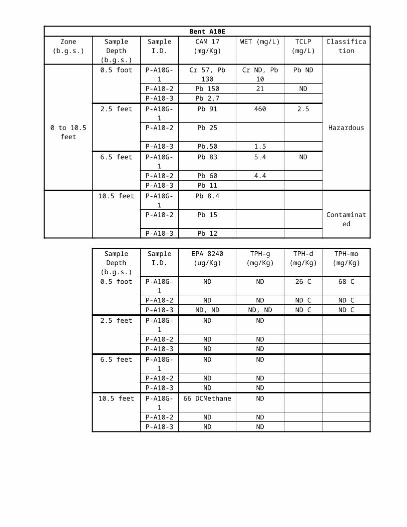
At the Contractor’s expense, additional installation tension tests and rotational capacity tests shall be performed by the Contractor on each rotational capacity lot, in the presence of the Engineer, if 1) any fastener is not used within 3 months after shipment to the jobsite, 2) fasteners are improperly handled, stored, or subjected to inclement weather prior to final tightening, or 3) if significant changes are noted in original surface condition of threads, washers or nut lubricant.
Failure of a job-site installation tension test or a rotational capacity test will be cause for rejection of all fasteners represented by the rotational capacity lot.
55-3.14F Inspection.—For all types of fastener assemblies, at least 10%, but no fewer than 2 bolts in each
high-strength bolted connection shall be inspected after tensioning in accordance with the requirements of Section 9, "Inspection," of the RCSC Specification. The Contractor shall be responsible for determining the job inspecting torque as specified in Section 9(b), "Arbitration Inspection," of the RCSC Specification. The procedure described for determining arbitration torque in steps 1 through 9 of the "Arbitration of Disputes Inspection Torque Method-Short Bolts," section of the SBH, shall replace Section 9(b)(2) of the RCSC Specification for determining the job inspecting torque for short bolts. Bolt tension shall be checked at locations selected by the Engineer. All work required to perform such inspection shall be done by the Contractor in the presence of the Engineer and in such a manner that the Engineer can read the torque wrench gage during checking.
Direct tension indicator washers shall not be used for bolt tightening on structural steel for this project.Use oversized washers in connections with slotted holes.An approved thread locking system, consisting of a cleaner, primer and anaerobic adhesive, shall be applied to
bolt and nut threads where shown on the plans. Lubricants and foreign materials shall be removed from the threaded areas of both parts using the cleaner and small wire brush. The primer shall be applied to cover the threaded areas of both parts. The anaerobic adhesive shall be applied to fill the male threads in the area of the final position of the nut. The nut shall be installed at the location or to the torque shown on the plans, and an additional fillet of anaerobic adhesive shall be applied completely around the exposed junctions of the nut and male part. Full compensation for furnishing and applying the thread locking system will considered as included in the contract price paid for the item of work requiring the system and no separate payment will be made therefor.
WELDING.--The third paragraph of Section 55-3.17, "Welding," of the Standard Specifications is amended to read:
The extent of radiographic testing on groove welds shall be in accordance with the requirements in ANSI/AASHTO/AWS D1.5, Subsection 6.7.1.2. In addition to the radiographic tests required, twenty-five percent of these same joints, in material in excess of 1/2 inch thickness, shall also be ultrasonically tested. Additional testing shall be performed on welds as noted on the plans.
Section 6.7.1 of ANSI/AASHTO/AWS D1.5 is amended to read:
Complete joint penetration groove welds in main members shall be QC tested by nondestructive testing. Unless otherwise specified, radiographic testing shall be used for examination of complete joint penetration groove welds in butt joints subject to calculated tension or reversal of stresses as shown on the plans. All complete joint penetration groove welds in T- and corner joints shall be tested by ultrasonic testing. Testing of complete joint penetration groove welds in butt joints in compression or shear may be done by RT or UT.
The flat side of all butt welded joints shall not deviate from flatness by more than 3/16 inch in a length of 2 feet centered over the weld joint.
CONTRACT NO. 04-043934REVISED PER ADDENDUM NO. 5 DATED APRIL 1, 1998

Table 2.2 of ANSI/ AASHTO/AWS D1.5 is superseded by the following table:
Base Metal Thickness of the Thicker Part Joined, in.
Minimum Partial Joint Penetration Groove Weld Size, in.*
Over 1/4 to 1/2 inclusive 3/16Over 1/2 to 3/4 inclusive 1/4Over 3/4 to 1 1/2 inclusive 5/16Over 1 1/2 to 2 1/4 inclusive 3/8Over 2 1/4 to 6 inclusive 1/2Over 6 5/8
*Except the weld size need not exceed the thickness of the thinner part.
Dimensional details and workmanship for welded joints in tubular and pipe connections shall conform to the provisions in Part A, Common Requirements of Nontubular and Tubular Connections and Part D, Specific Requirements for Tubular Connections, in Section 2 of AWS D1.1.
Preheat and interpass temperatures for welding of Grades 70W, 100, and 100W shall be determined in accordance with AWS D1.5 Section 4.2 and Annex VIII.
Welder qualifications for all welders welding on steel Grade 70, 70W, 100 and 100W shall be established specifically for this project, using each grade of steel to be welded. Previous welder certification shall not apply.
BEARINGS AND ANCHORAGES.--The last three paragraphs in Section 55-3.19, "Bearings and Anchorages," of the Standard Specifications are amended to read:
Nonshrink grout to be placed below masonry plates or bearing plates of the bearing assemblies and in anchor bolt sleeves or canisters shall conform to the requirements for “Nonshrink Grout” in the special provisions.
Anchor bolts shall be either headed bolts, installed with or without pipe sleeves or corrugated metal canisters as detailed on the plans. The anchor bolts shall be carefully installed to permit true positioning of the bearing assemblies.
When anchor bolts are installed in pipe sleeves or metal canisters, the pipes or canisters shall be completely filled with nonshrink grout . Such grouting and the construction of grout pads under masonry plates, if required, shall be completed and cured prior to loading the new bearings .
At the "A4E" Approach Span and the "D" Line bearing replacements, the installed deviation from level for the
upper surface of the masonry plates shall not exceed 0.0033 radians in any direction. The installed deviation from level for the lower surface of the sole plates shall not exceed 0.0033 radians in any direction. Verification of the masonry plate levelness shall be made by the Engineer after the placement of the concrete below the bearing plate. Masonry and sole plates out of tolerance shall be rejected.
WATERPROOF GREASE.-- Waterproof grease shall conform to the requirements of Military Specification: MIL-S-8660. A uniform film of grease shall be applied to the shear lock surfaces as shown on the plans.
ERECTION.-- Erection work is subject to the following restrictions:
All erection work performed over railroad property shall be performed with protective covers to prevent any materials, equipment, or debris from falling onto the railroad property
Except for minor erection work, no erection work shall be performed over an active gas line. Protective covers over active gas line are required while performing minor erection work.
Except for minor erection work, no erection work shall be performed above or within 20 feet horizontally of the traveled way while the traveled way is open to public traffic. Protective covers over the traveled way are required while performing minor erection work.
CONTRACT NO. 04-043934REVISED PER ADDENDUM NO. 5 DATED APRIL 1, 1998

Minor erection work, defined as items such as bolt installation, drilling, chipping, grinding or cutting, shall be limited to operations that will not reduce the structural strength or stability of the bridge or member to be modified during erection, or any element thereof, to a level which in the judgment of the Engineer would constitute a hazard to the public. Such work shall also be limited to operations that cannot cause equipment, debris or any other material to fall onto the traveled way, railroad property, or gas line.
Protective covers shall be used to prevent equipment, debris, or any other material to fall onto the traveled way, railroad property, or active gas line. The covers shall be of sufficient strength to support all loads, including but not limited to impact loads from falling material and equipment, and are sufficiently tight to prevent fine material from sifting down onto the traveled way, railroad property, or gas line. Over the traveled way and railroad property, protective cover shall extend horizontally, in both the longitudinal (parallel to bridge) and transverse (perpendicular to bridge) directions, beyond the limit of the work underway at least one-quarter of the maximum vertical distance between the work and the protective cover, but in no case less than 4 feet beyond the limit of the work underway. Temporary support shoring, temporary bracing, and protective covers shall not encroach closer than 8 feet horizontally and 15 1/2 feet vertically above any traffic lane or shoulder that is open to traffic. Over the gas line, protective cover shall extend in the longitudinal direction beyond the limit of the work underway at least one-quarter of the maximum vertical distance between the work and the protective cover, but in no case less than 4 feet beyond the limit of the work underway. Over the gas line, protective cover shall extend in the transverse direction a minimum of 2 feet horizontally beyond the extreme faces of the gas line. The gas line protective cover shall not be supported from the gas line or gas line supports.
The Contractor shall submit an erection procedure which describes, in detail, the methods to be followed to deliver, handle, lift and support structural steel members above the traveled way prior to their being permanently incorporated to the structure. The procedure shall will be coordinated with the requirements for lane closures and/or bridge closures contained in”Order of Work”and “Maintaining Traffic”elsewhere in these special provisions, and with the structural steel removal sequence below. Requirements for the erection plan shall meet all of the requirements of the removal plan, including shoring, bracing and protective covers.
Prior to closing a roadway to traffic to accommodate structural steel erection or removal, the Contractor shall have all necessary men, materials and equipment at the site as needed to proceed with the removal work in an expeditious manner. While the roadway is closed to traffic, work shall be pursued promptly and without interruption until the roadway is reopened to public traffic.
REMOVAL.-- Removal of structural steel shall include removal of entire members and connections, and removal of portions of existing members, as shown on the plans and as directed by the Engineer. Removing structural steel shall conform to the requirements in Section 15-4, "Bridge Removal," of the Standard Specifications and these special provisions.
All removal shall be done in a manner that avoids damage to existing members or structures to remain and assures that people, property, and improvements will not be endangered.
All removed structural steel that is not to be salvaged or used in the reconstruction shall become the property of the Contractor and shall be disposed of outside the highway right of way in accordance with the provisions in Section 7-1.13 of the Standard Specifications.
Removal of welds on existing steel shall be by mechanical means, as approved by the Engineer. The Contractor shall submit a complete structural steel removal plan to the Engineer detailing procedures
and sequence for removing structural steel , including all features necessary to remove the structural steel in a safe and controlled manner. The plan shall be coordinated with the allowable lane closures and allowable bridge closures specified elsewhere in these special provisions.
The structural steel removal plan furnished shall include the following:
The structural steel removal sequence for the entire structure, including staging ofremoval;Equipment locations and equipment loads on the structure during removal operations;Temporary support shoring, falsework or temporary bracing;A typical removal procedure where the structure is located over or adjacent to the traveled way;Locations where work is to be performed over traffic or railroad property;, or gas line;Details and locations of protective covers or other measures to assure that people, property and
improvements will not be endangered; andDetails and locations of equipment used to control the release of hazardous materials into the
environment.
CONTRACT NO. 04-043934

REVISED PER ADDENDUM NO. 5 DATED APRIL 1, 1998

Temporary support shoring or temporary bracing for structural steel removal and protective covers for minor erection work or preliminary work shall be designed and constructed in conformance with the provisions in Section 51-1.06, "Falsework," of the Standard Specifications and these special provisions. For protective covers over the gas line, 10 sets of working drawings shall be submitted to the Engineer.
The following additional requirements apply to the removal of structural steel that is over or adjacent to roadways that may be closed to public traffic for only brief periods of time:
Prior to closing a roadway to traffic to accommodate bridge removal operations, the Contractor shall have all necessary men, materials and equipment at the site as needed to proceed with the removal work in an expeditious manner. While the roadway is closed to traffic, work shall be pursued promptly and without interruption until the roadway is reopened to public traffic.
All removal operations shall be performed during periods of time that the roadway is closed to public traffic except as specified herein for preliminary work.
Preliminary work shall be limited to operations that will not reduce the structural strength or stability of the bridge or member to be removed, or any element thereof, to a level which in the judgment of the Engineer would constitute a hazard to the public. Such preliminary work shall also be limited to operations that cannot cause debris or any other material to fall onto the traveled way, railroad property or gas line. Protective covers shall be used in order to perform preliminary work such as rivet or bolt removal, chipping, grinding or cutting subject to approval of the Engineer. The covers shall be of sufficient strength to support all loads, including but not limited to impact loads from falling material and equipment and are sufficiently tight to preventfine material from sifting down onto the traveled way. Over traveled way and railroad property, protective cover shall extend horizontally, in both the longitudinal (parallel to bridge) and transverse (perpendicular to bridge) directions, beyond the limit of the work underway at least one-quarter of the maximum vertical distance between the work and the protective cover, but in no case less than 4 feet beyond the limit of the work underway.Temporary support shoring, temporary bracing, and protective covers shall not encroach closer than 8 feet horizontally from the edge and 15 1/2 feet vertically above any traffic lane or shoulder that is open to traffic. Over the gas line, protective cover shall extend in the longitudinal direction beyond the limit of the work underway at least one-quarter of the maximum vertical distance between the work and the protective cover, but in no case less than 4 feet beyond the limit of the work underway. Over the gas line, protective cover shall extend in the transverse direction a minimum of 2 feet horizontally beyond the extreme faces of the gas line. The gas line protective cover shall not be supported from the gas line or gas line supports.
The removal operations shall be conducted in such a manner that the portion of the structure not yet removed remains in a stable condition at all times.
The following additional requirements apply to protective covers:
The construction and removal of the protective cover and the installation and removal of temporary railings shall conform to the requirements under "Order of Work" "Maintaining Traffic" and "Temporary Railings" of these special provisions.
The protective cover shall prevent any materials, equipment or debris from falling onto the traveled way, railroad property, or gas line. The protective cover shall have a minimum strength equivalent to that provided by good, sound Douglas fir planking having a nominal thickness of 2 inches. Additional layers of material shall be furnished as necessary to prevent fine materials or debris from sifting down upon the traveled way and shoulders.
Before removal, the protective cover shall be cleaned of all debris and fine material.The protective cover shall provide minimum clearances as required under "Relations with Railroad
Company" of these special provisions for the passage of railroad traffic.
The Contractor shall proceed with the removal of the existing structural steel in accordance with the sequence of work shown on the plans and in these special provisions. In the event that removal of any element of the bridge(including but not limited to x-frame members, top or bottom laterals, sway frames, portal frames, holddowns, and tower or other elements) may weaken the structure, the Contractor shall provide additional shoring, falsework or bracing as required to maintain structural stability. The shoring, falsework or bracing shall be designed to meet the vertical and lateral load requirements as shown on the plans and as specified in the Section “Falsework” elsewhere in these special provisions. In the event that the Contractor determines that shoring, bracing or falsework is required in addition to that shown on the plans, in the Standard Specification, or in these special provisions, based on the Contractor’s methods, equipment, or sequence of operation, the Contractor shall provide such shoring, bracing or falsework.
CONTRACT NO. 04-043934REVISED PER ADDENDUM NO. 5 DATED APRIL 1, 1998

The Contractor shall submit to the Engineer working drawings, with design calculations, for the proposed structural steel removal plan including all shoring, bracing or falsework necessary. The structural steel removal plan shall be prepared by an engineer who is registered as a Civil Engineer in the State of California. The design calculations shall be adequate to demonstrate the stability of the structure during all stages of the removal operations. Calculations shall be provided for each stage of structural steel removal.
The structural steel removal plan shall conform to the requirements in Section 5 -1.02, "Plans and Working Drawings," of the Standard Specifications. The number of sets of drawings and design calculations and times for review for any bridge removal plans shall be the same as specified for falsework working drawings in Section 51-1.06A, "Falsework Design and Drawings," of the Standard Specifications.
The time to be provided for the Engineer's review of the working drawings for removing structural steel, per submittal , shall be as follows:
Structure orPortion of Structure
Review Time - Weeks
“A4E” Main Spans 6“A4E” Approach 10
“D” Line 3
For structural steel removal over railroads, approval by the Engineer of the structural steel removal plans will be contingent upon the drawings being satisfactory to the railroad company involved.
Approval by the Engineer of the structural steel removal plans or field inspection performed by the Engineer will in no way relieve the Contractor of full responsibility for the structural steel removal plan and procedure.
Prior to proceeding with structural steel removal , an engineer for the Contractor who is registered as a Civil Engineer in the State of California shall inspect the temporary support shoring, including temporary bracing and protective coverings, for conformity with the working drawings. The Contractor's registered engineer shall certify in writing that the temporary support shoring, including temporary bracing and protective coverings, substantially conform to the details on the working drawings, and that the material and workmanship are satisfactory for the purpose intended. A copy of this certification shall be available at the site of the work at all times.
The Contractor's registered engineer shall be present at the bridge site where structural steel removal operations are in progress. The Contractor's registered engineer shall inspect the structural steel removal operation and report in writing on a daily basis the progress of the operation.A copy of the daily report shall be available at the site of the work at all times. Should an unplanned event occur, the Contractor's registered engineer shall submit immediately to the Engineer for approval, the procedure of operation proposed to correct or remedy the occurrence.
SEQUENCE OF REMOVAL OPERATIONS.--Structural steel removal work shall proceed in the sequence
shown on the plans and in these special provisions unless approved in writing by the Engineer. The following requirements shall apply to structural steel removal and erection:
Truss and Tower Member Connections: When gusset plates are to be removed from both sides of a joint, construction shall be limited to one side of the connection at a time, except as noted below or on the plans.
Top Lateral Cross-Bracing: At top lateral cross bracing, gusset plates are located on two faces of the panel, the top face and the bottom face. All retrofit of gusset plates within a panel shall be accomplished one face at a time, either all the top face gusset plates shall be retrofit first or all the lower face gusset plates shall be retrofit first. A panel shall be defined as the structure between two adjacent even-numbered panel points, inclusive of the transverse struts at the panel points.
Sway/Portal Braces: No work is permitted on connections of sway or portal braces within any span while any connections within the top lateral bracing of that span are partially or completely disassembled. For this requirement, the superstructure is considered to consist of two anchor spans, four cantilever spans, two suspended spans, and one tower span.
Shock Transmission Devices and Bottom Chord Replacement: Complete chord replacement and shock transmission device work at one end of a suspended span before beginning work at the opposite end of that suspended span. Work shall not occur on both east and west chords near a suspended span simultaneously.
CONTRACT NO. 04-043934REVISED PER ADDENDUM NO. 5 DATED APRIL 1, 1998

Bottom Laterals: At least one cross brace, defined as a horizontal member extending from one chord through a floor beam to the other chord, shall have all top gussets or all bottom gussets completely bolted at all times. These members and gussets required to be in place may be existing construction, new construction, or a combination of new and existing construction.
Work on bottom chords between panel points L44 and L46 shall not coincide with work on bottom chord lateral bracing between panel points L44 and L46, and work on bottom chords between panel points L70 and L72 shall not coincide with work on bottom chord lateral bracing between panel points L70 and L72.
Truss Anchors/Sliding Bearing Devices: At Abutment 1 and at Pier 5, complete installation of new bearing device at one chord before removal of existing truss anchor at opposite chord. Work may proceed on truss anchors at Abutment 1 and Pier 5 concurrently.
Towers 2 and 4: Connect existing base plate to existing masonry plate before removing lateral or chevron brace connections. Install temporary vertical bracing before removing connections of lower tier (between elevations 18.0 and 59.0) chevron braces. At each tower, only one lower tier chevron brace may be disconnected at one time. Complete work on all lower tier chevrons, transverse horizontal struts at elevation 22.0, and horizontal cross bracing at elevation 22.0 before removing existing north-south horizontal struts at elevation 22.0 between tower legs.
At each tower, complete all work on lower tier chevrons, all tower base shear locks, and transfer girders before raising tower legs or otherwise modifying the base of the tower legs. Raise or lower only one tower leg at a time. Close the bridge to traffic while raising or lowering is in progress.
Tower 3: At each tower leg complete bolting of exterior hold-down girder to leg, longitudinal horizontal strut, and longitudinal chevron before disassembly of gusset plate connection at interior of tower leg.
Existing horizontal cross braces at elevation 22.0 and elevation 88.07 may be used to brace the tower during construction. Stage work to maintain at least one existing brace per elevation between panel points 56 and 58 and one existing brace per elevation between panel points 58 and 60.
Tower 3 Transverse Chevrons: At each transverse chevron braced frame install temporary vertical support before removing the connection of the lower tier (between elevation 18.0 and 56.2) chevron braces. Only one lower tier transverse chevron may be disconnected at a time.
Tower 3 connection to bottom chord, panel point L58: Work on the tower diagonal connections to the bottom chord at panel point L58 at one side of the structure shall be complete before disconnecting the tower diagonal to bottom chord connection at the opposite side of the structure. Work on the tower diagonal connections to bottom chords at panel point L58 shall not coincide with work on the bottom laterals between panel points L56 and L60.
CONTRACT NO. 04-043934REVISED PER ADDENDUM NO. 5 DATED APRIL 1, 1998

10-1.72 MISCELLANEOUS METAL (BRIDGE)Miscellaneous metal (bridge) shall conform to the provisions for miscellaneous bridge metal in Section 75,
"Miscellaneous Metal," of the Standard Specifications and these special provisions.Attention is directed to “Welding Quality Control” elsewhere in these special provisions.Miscellaneous metal (bridge) shall consist of the miscellaneous bridge metal items listed in Section 75 -1.03,
"Miscellaneous Bridge Metal," of the Standard Specifications, and the following:
Ladders with safety posts and safety climb devices Handrails Anchor bolts Catwalk Signs Pipe supports mounted on steel bridge and on concrete Pier 5.
A ladder safety post and safety climb device shall be furnished and installed for each permanent ladder longer
than 8 feet installed by the Contractor. Ladder safety post shall be a telescoping tubular safety post, spring balanced and automatically locking in the raised position, with a release lever for unlocking. Safety post may be fit to ladder rungs. The safety climb device shall meet or exceed Federal Specification RR-S-001301 and OSHA Regulation No. 1910.27. Safety climb device shall have a removable extension kit with tiedown rod, mandril, and carrier rail. The safety climb device shall be installed in accordance with the manufacturer’s recommendations and shall enable a worker to be attached to the device at all times and to operate freely in a normal position during climbing and decent without having to remove hands from the ladder to operate the system effectively. Both the safety post and the safety climb device shall be constructed of aluminum or galvanized steel and spring mechanisms shall be corrosion resistant alloys. Details of the safety post and safety climb device shall be submitted to the Engineer for approval prior to ordering or fabricating any material.
Each leaf of the hinged metal access doors shall be fitted with a hold open device which engages when the door is opened. Hinged door leafs weighing more than 100 pounds shall be spring assisted.
The Contractor shall furnish and install a warning sign at the truss chord end of the catwalks on the “A4E” Mainspan. The sign inscription shall read “WARNING - Catwalk has low overheads and obstructions. Hard Hats must be worn.” Signs shall be sheet steel, not less than 0.048-inch thick (18-gage) with baked-on enamel coating. Signs shall have a white background with contrasting red letters. Red letters shall be 2 inches minimum in height.
An approved thread locking system, consisting of a cleaner, primer and anaerobic adhesive, shall be applied where shown on the plans. Lubricants and foreign materials shall be removed from the threaded areas of both parts using the cleaner and small wire brush. The primer shall be applied to cover the threaded areas of both parts. The anaerobic adhesive shall be applied to fill the male threads in the area of the final position of the nut. The nut shall be installed at the location or to the torque shown on the plans, and an additional fillet of anaerobic adhesive shall be applied completely around the exposed junctions of the nut and male part. Full compensation for furnishing and applying the thread locking system shall be considered as included in the contract price paid for the item of work requiring the system and no separate payment will be made therefor.
Self-tapping screws shall be hex-head, stainless steel or monel metal, installed in holes drilled to fit the self-tapping screws.
The third subparagraph of the second paragraph of Section 75-1.03, "Miscellaneous Bridge Metal," of the Standard Specifications is amended to read:
3. Manhole frames and covers, frames and grates, ladder rungs, guard posts, and access door assemblies.
The third subparagraph of the eleventh paragraph of Section 75-1.03, "Miscellaneous Bridge Metal," of the Standard Specifications is amended to read:
Cast-in-place inserts shall be ferrule loop or cast iron type.All metal parts of anchorage devices shall be fabricated from steel, except iron castings for cast-in-place inserts
shall be malleable iron or ductile iron.All metal parts of anchorage devices, except mechanical expansion anchors and iron castings for cast-in-place
inserts, shall be hot-dip or mechanically galvanized. Mechanical expansion anchors may be hot-dip or mechanically galvanized, made from stainless steel, or coated with electrodeposited zinc conforming to the requirements of ASTM Designation: B 633. Iron castings shall be mechanically galvanized.
CONTRACT NO. 04-043934REVISED PER ADDENDUM NO. 5 DATED APRIL 1, 1998

Add the following to the fifth subparagraph of the eleventh paragraph of Section 75-1.03, "Miscellaneous Bridge Metal" of the Standard Specifications:
Structural steel material used for fabricating pipe supports, hangers, and anchors for the new pipeline shall conform to ASTM A36. Bolts used for connections in the pipe supports, hangers, and anchors shall conform to ASTM A325 Type 1. Nuts shall conform to ASTM A563 including Appendix X1. Washers shall conform to ASTM F436, plain (uncoated). Bolts, nuts, and washers shall be non-zinc-coated.
Welding of the pipe supports, hangers, and anchors shall be in accordance with AWS D1.1 using minimum Grade E70 electrodes.
Anchorage of pipe supports, hangers, and anchors to existing concrete at Pier 5 shall be as shown on contract plans, utilizing the HILTI HVA anchoring system. Threaded rods shall meet the requirements of ASTM A36 for the "HAS Standard" system and ASTM A193 Grade B7 for the "HAS Super" system. Nuts shall conform to ASTM A563. Washers shall conform to ASTM F436. All rods, nuts, and washers shall be zinc plated to ASTM B633 SC1. Installation shall be in accordance with all manufacturer recommendations and requirements. Subject to engineer’s approval, alternative anchoring systems may be used, provided such anchors meet or exceed the capacities (ultimate bond strength, and steel tensile and shear strengths for given anchor diameters and embedment depths as shown in contract plans) of the HILTI HVA system.
Surfaces of all new steel members shall be cleaned and painted as specified in Section 10-1.64 "Clean and Paint Structural Steel" of these special provisions for new metal surfaces.
All Existing metal surfaces that will come in contact with new steel members, bolts, nuts, or washers shall be cleaned and painted as follows: All such surfaces shall be steamed cleaned in accordance with Section 59-2.05, "Steam Cleaning," of the Standard Specifications, and shall be dry blast cleaned in accordance with Section 10-1.64 "Clean and Paint Structural Steel" of these special provisions. Prior to installation of pipe supports, such surfaces shall receive one undercoat of inorganic zinc, to be applied in a single application, within 4 hours after blast cleaning, providing a total dry film thickness of not less than 1 mil nor more than 4 mils. Zinc coating shall conform to requirements of Section 10-1.64 "Clean and Paint Structural Steel" of these special provisions.
Surfaces of existing steel which have been covered with inorganic zinc undercoat and remain exposed after installation of pipe support brackets shall receive a minimum of 2 finish coats of paint in accordance with Section "Clean and Paint Structural Steel" of these special provisions.
After all bolts of each pipe support bracket have been tightened to the final specified tension values, all loosened or damaged paint in areas in the vicinity of the completed connection shall be cleaned and spot painted in accordance with Section 59-2.12, "Painting," of the Standard Specifications.
Seams between existing structural members and existing gusset plates, and seams between existing gusset plates and new pipe support baseplates which exceed 6 mils in width that would retain moisture shall be caulked in accordance with paragraph 3 of Section 59-2.12, "Painting," of the Standard Specifications.
All seams between vertical concrete surfaces and pipe support plates shall be caulked in accordance with paragraph 3 of Section 59-2.12, "Painting," of the Standard Specifications.
Bolted connections to bridge gusset plates shall be made as specified under "Fabrication" in Section "Steel Structures" of these special provisions. The Contractor's attention is also directed to section 10-1.61 "Bolt or Rivet Removal and Replacement" of these special provisions.
CONTRACT NO. 04-043934REVISED PER ADDENDUM NO. 5 DATED APRIL 1, 1998
10-1.72A PIPE SUPPORT INSTALLATION PROCEDUREThe purpose of this procedure is to provide the Contractor with a sequential instruction for installing new pipe
supports to existing bridge structures, as required to support the new natural gas pipeline on the east side of the Carquinez Bridge.
The requirements and limitations prescribed in this procedure is an attempt to balance the goals of obtaining a complete and satisfactory pipe support system, expediting construction schedule, and minimizing construction costs, against the goals of ensuring safety of motorists, workers, and bridge structure, and minimizing detrimental impact on traffic. Therefore, the Contractor is strongly encouraged to submit alternative procedures, which may affect these goals more efficiently, for consideration and approval by the Engineer.
This installation instruction describes the pipe support installation and construction methods to:
selectively remove existing structural fasteners from gusset plates and structural members at locations where new pipe supports are to be installed;
re-drill existing gusset plate and structural member bolt holes to sizes which can accept fasteners required for the new pipe support configurations;
clean and preserve structural areas exposed by fastener removal and drilling operations; temporarily replace (in sequence) all removed fasteners after re-drilling, with tapered pins of structural
quality, which shall maintain adequate structural support in the installation area, preclude misalignment of the gusset to member connections during installation operations, and act as alignment guides to slide the new pipe support baseplate into place on the bridge surface; and
replace the temporary tapered pins (in sequence) with new structural bolted connections, securing and torqueing the pipe support base plate to gusset plate and structural members to provide permanent replacement structural bearing and pipe support assemblies.
The Contractor is responsible for conducting pipe support installation activities in accordance with the contract plans, specifications, special provisions, and this instruction. The Contractor shall notify the Engineer and receive written approval prior to performing pipe support installation work which deviates from the instructions herein.
REQUIREMENTS AND INSTALLATION PREREQUISITES.--Prior to commencing new pipe support installation work, Contractor shall demonstrate to the Engineer's satisfaction that all utilities and other items which may interfere with the installation of the supports have been relocated.
Contractor shall verify prior to commencing pipe support installation work that all new pipe support baseplates have been fabricated with bolt hole patterns which match the structural areas where bolts are to be removed and bolt holes re-drilled.
Contractor shall verify that the baseplate dimensions and bolt hole locations for the pipe supports to be installed are such that they will allow proper alignment.
Proper alignment is critical for subsequent pipe installation (by others), which will be performed by pulling newly fabricated pipe through the pipe supports along the full length of the retrofitted bridge.
Allowable alignment tolerances for the pipe supports are ± 1/4" horizontally and vertically.Pipe support installation work shall not be attempted if wind speeds at jobsite exceed 30 miles per hour.Before any bolt removal operations start, at least three traffic lanes on the east side of the bridge (lanes 2, 3, and
4) shall be closed to traffic in order to minimize live loads on the bridge. Traffic lanes shall not be re-opened until all open bolt holes or pins have been replaced in the gusset plates with properly torqued ASTM A325 bolts.
The combined weights of all vehicles, equipment, materials, personnel, and all other supplies located within 120 feet of any panel point where bolts are being replaced shall not exceed 20 tons in lanes 3 and 4. In addition, traffic in lane 2 shall be limited to a single vehicle not exceeding 20 tons.
Bolt removal and installation can be simultaneously performed on more than one member to gusset plate connection as long as any two connections being worked on are at least 300 feet apart, and work is performed in the sequence described in the following section.
The bolt removal and installation effort shall not commence until trial installations have been successfully performed at the north end of the bridge, in the presence of and to the satisfaction of the engineer. This requirement shall be satisfied by successfully installing pipe supports at panel points 114 and 115, following the procedures and requirements of this document, removing four (4) rows of bolts at a time as per Item 1 of the Procedure. Contractor shall submit a monitoring plan for bridge displacement for review and approval by the Engineer. In accordance with the monitoring plan, Contractor shall continuously monitor bridge for excessive displacement and structural overstress as a result of bolt removal. Should relative displacement between gusset plate and structural member exceed 1/8", Contractor shall stop bolt removal, take all necessary actions to ensure the safety of personnel and motorists, to prevent damage to bridge, to restore the original bridge condition and to inform engineer of all problems encountered.
CONTRACT NO. 04-043934ADDED PER ADDENDUM NO. 5 DATED APRIL 1, 1998

PROCEDUREA maximum of four (4) rows of bolts may be removed at a given time with resulting bolt holes left unsupported
by pins (as described in Item 4 of the Procedure).Upon removal of existing bolts, the exposed gusset plate and structural member surfaces shall be thoroughly
cleaned of all rust, paint, debris and imperfections, and prepared with suitable corrosion preventing coatings in accordance with the project specifications.
Exposed bolt holes shall be re-drilled to accommodate the 1 1/8" diameter replacement bolts.Sixteen inch long tapered pins, made with material conforming to requirements of ASTM A307, with diameter
varying from 1 5/16" to 1 1/16", shall be driven into the open holes for temporary bearing support. The pins should be driven to snug fit to avoid relative displacement between the structural member and the gusset plate. Pins shall be inserted from the west side pointing east.
Once the first group of bolts are replaced by pins, work can proceed to another group of bolts until all bolts to be replaced in the subject gusset plate have been replaced by pins and the gusset plates and member surfaces are properly cleaned and painted for pipe support installation.
Once all gusset plate and support member holes in one connection have been re-drilled and inserted with tapered pins, the pipe support base plate shall be installed by sliding it over the inserted pins.
To secure the pipe support in place, the center row of baseplate pins will be the first ones to be replaced with the 1 1/8" bolts, working on one pin at a time from the center row out.
As soon as a pin is replaced with a bolt, the bolt should be tightened to the tension values shown in Table 4 of "Specification for Structural Joints using ASTM A325 or A490 Bolts," approved by the Research Council on Structural Connections of the Engineering Foundation, Nov. 1985, and published in the American Institute of Steel Construction's "Manual of Steel Construction," Ninth Edition, 1989.
Once the center row of pins have been replaced with bolts, the rest of the pins can be replaced with bolts one at a time.
Workers shall continue replacing tapered pins with torqued bolts, first with the line of bolts above the central row and alternating with the line of bolts below the central row.
Workers shall continue cycling bolt for pin replacement, alternating between the top and the bottom until the top-most and bottom-most rows are reached and completed.
Prior to completing each pipe support installation, Contractor shall assure that all bolted connections have been re-torqued to the values specified in Item 8 of the Procedure.
At panel point number 1, where the number of bolt holes in a pipe support bracket exceeds the number of available existing holes, provisions shall be made to drill additional holes into the existing gusset plate and structural member before re-drilling existing bolt holes.
To avoid interference with installation, the W8x35 welded frame at pipe support details 2 and 9, as shown on contract plans, shall be installed only after all baseplate bolts have been installed.
Special care shall be exercised for the installation of concrete anchors at Pier 5. Installation shall be in strict accordance with all manufacturer recommendations and requirements, utilizing a heavy duty rotary hammer drill. To ensure sufficient setting time and proper curing for concrete anchors installed at Pipe Support Details 3 and 4 (as shown on contract plans), the temperature of all adhesive capsules and threaded rods shall not exceed 45 F at time of insertion into properly prepared holes.
Attention is directed to "Bridge Utility and Maintenance Equipment Work," elsewhere in these special provisions, for information on existing facilities that are known to be affected by the pipe support work, such as maintenance ladders and platforms, light beacons, seismic instrumentation, and a water drain near Abutment 1.
The second paragraph in Section 75-1.06, "Measurement," of the Standards Specifications is amended to read:
Scale weights will not be required when miscellaneous iron and steel, miscellaneous bridge metal, miscellaneous metal (restrainer), or pumping plant metal work are designated as final pay items in the Engineer's Estimate.
Full compensation for furnishing and installing a ladder safety post and safety climb device for each ladder, for providing a hold open device and spring assist on access doors shall be considered as included in the contract unit price paid per pound for miscellaneous metal bridge and no additional compensation will be allowed therefor.
The contract unit prices paid for the various types of miscellaneous metal pipe supports (bridge), entitled Pipe Support Detail 1 thru 9, shall include full compensation for furnishing all labor, materials, tools, equipment, and incidentals and for doing all the work involved in the various miscellaneous metal pipe supports (bridge), complete in place, including fabrication, installation and painting, as shown on the plans, as specified in the Standard Specifications and these special provisions, and as directed by the Engineer.
CONTRACT NO. 04-043934ADDED PER ADDENDUM NO. 5 DATED APRIL 1, 1998

ENGINEER'S ESTIMATE04-043934
Item Item Code
Item Unit of Measure
Estimated Quantity
Unit Price Item Total
81 198001 IMPORTED BORROW TON 5,020
82(S)
203003 STRAW (EROSION CONTROL) TON 8
83(S)
203014 FIBER (EROSION CONTROL) TON 2
84(S)
203040 SEED (EROSION CONTROL) LB 170
85(S)
203056 COMMERCIAL FERTILIZER (EROSION CONTROL)
TON 1
86(S)
203061 STABILIZING EMULSION (EROSION CONTROL)
LB 460
87 260301 CLASS 3 AGGREGATE BASE CY 1,120
88 390155 ASPHALT CONCRETE (TYPE A) TON 10,700
89 394040 PLACE ASPHALT CONCRETE DIKE (TYPE A)
LF 100
90 394042 PLACE ASPHALT CONCRETE DIKE (TYPE B)
LF 380
91 394044 PLACE ASPHALT CONCRETE DIKE (TYPE C)
LF 130
92 394048 PLACE ASPHALT CONCRETE DIKE (TYPE E)
LF 2,790
93(S)
490604 30" CAST-IN-DRILLED-HOLE CONCRETE PILING
LF 17,750
94(S)
046821 48" CIDH PILING (W/PERMANENT CASING)
LF 1,440
95(S)
500010 PRESTRESSING LS LUMP SUM LUMP SUM
96(S)
046823 PRESTRESSING HIGH STRENGTH ROD (LOCATION A)
LS LUMP SUM LUMP SUM
97(S)
046824 PRESTRESSING HIGH STRENGTH ROD (LOCATION B)
LS LUMP SUM LUMP SUM
98(S)
046825 PRESTRESSING HIGH STRENGTH ROD (LOCATION C)
LS LUMP SUM LUMP SUM
99(S)
046826 PRESTRESSING CONCRETE EXTERNAL TENDON (LOCATION A)
LS LUMP SUM LUMP SUM
100(S)
046827 PRESTRESSING CONCRETE EXTERNAL TENDON (LOCATION B)
LS LUMP SUM LUMP SUM
7REVISED PER ADDENDUM NO. 5 DATEDAPRIL 1, 1998
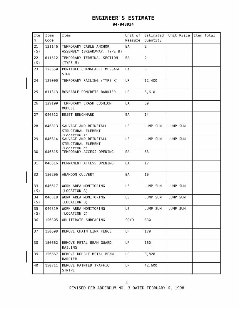
ENGINEER'S ESTIMATE04-043934
Item Item Code
Item Unit of Measure
Estimated Quantity
Unit Price Item Total
101(S)
500060 TIEDOWN ANCHOR EA 8
102(F)
510051 STRUCTURAL CONCRETE, BRIDGE FOOTING
CY 5,900
103(F)
510053 STRUCTURAL CONCRETE, BRIDGE CY 6,066
104(S-F)
510060 STRUCTURAL CONCRETE, RETAINING WALL
CY 135
105(S-F)
510502 MINOR CONCRETE (MINOR STRUCTURE)
CY 80
106(S)
510526 MINOR CONCRETE (BACKFILL) CY 8
107(S-F)
511064 FRACTURED RIB TEXTURE SQFT 1,120
108 511106 DRILL AND BOND DOWEL LF 30,180
109 511109 DRILL AND BOND DOWEL (EPOXY CARTRIDGE)
EA 44
110(S)
046828 PRECAST ABUTMENT CAP BEAM EA 2
111(S)
515010 INSTALL STUD CONNECTORS EA 4,899
112(S)
515063 CORE CONCRETE (4") LF 470
113(S)
515064 CORE CONCRETE (5") LF 200
114(S)
515065 CORE CONCRETE (6") LF 1,170
115(S)
515066 CORE CONCRETE (7") LF 300
116(S)
046830 CORE CONCRETE (2") & PRESSURE GROUT
LF 4,440
117(S)
046831 CORE CONCRETE (2 1/2") & PRESSURE GROUT
LF 5,770
118(S)
046832 CORE CONCRETE (3") AND PRESSURE GROUT
LF 360
119(S)
046833 CORE CONCRETE (4") & PRESSURE GROUT
LF 4,820
120(S)
046834 CORE CONCRETE (5") AND PRESSURE GROUT
LF 860
8REVISED PER ADDENDUM NO. 5 APRIL 1, 1998

ENGINEER'S ESTIMATE04-043934
Item Item Code
Item Unit of Measure
Estimated Quantity
Unit Price Item Total
121(S)
046835 ELASTOMERIC PAD EA 18
122(S)
046836 SLIDING BEARING DEVICE EA 4
123(S)
046837 PTFE SPHERICAL BEARING EA 3
124(S)
519001 WATERSTOP LF 10
125(S-F)
520102 BAR REINFORCING STEEL (BRIDGE)
LB 3,864,500
126(S-F)
520106 BAR REINFORCING STEEL (EPOXY COATED)
LB 7,440
127(S-F)
520110 BAR REINFORCING STEEL (EPOXY COATED) (BRIDGE)
LB 1,085,000
128(F)
530100 SHOTCRETE CY 526
129(F)
540050 SEAL CONCRETE SURFACE SQFT 24,000
130(S-F)
550110 COLUMN CASING LB 715,000
131(S)
046838 REPLACE BOLT EA 32,952
132(S)
046839 REMOVE RIVET (2 PLY) EA 2,584
133(S)
046840 REMOVE RIVET (> 2 PLY) EA 2,400
134(F)
550203 FURNISH STRUCTURAL STEEL (BRIDGE)
LB 5,492,000
135(F)
550204 ERECT STRUCTURAL STEEL (BRIDGE)
LB 5,492,000
136 562004 METAL (RAIL MOUNTED SIGN) LB 200
137 562007 ROADSIDE SIGN (METAL POST) EA 5
138 566011 ROADSIDE SIGN - ONE POST EA 10
139 566012 ROADSIDE SIGN - TWO POST EA 4
140 568001 INSTALL SIGN (STRAP AND SADDLE BRACKET METHOD)
EA 2
9REVISED PER ADDENDUM NO. 5 APRIL 1, 1998

ENGINEER'S ESTIMATE04-043934
Item Item Code
Item Unit of Measure
Estimated Quantity
Unit Price Item Total
161(S)
714039 21" CLAY SEWER PIPE LF 230
162(S)
719200 SEWER MANHOLE EA 5
163(S)
721410 CONCRETE (GUTTER LINING) CY 6
164 731502 MINOR CONCRETE (MISCELLANEOUS CONSTRUCTION)
CY 380
165(S-F)
750001 MISCELLANEOUS IRON AND STEEL
LB 9,394
166(S-F)
750498 MISCELLANEOUS METAL (RESTRAINER - CABLE TYPE)
LB 131,900
167(S-F)
750499 MISCELLANEOUS METAL (RESTRAINER - ROD TYPE)
LB 7,100
168(S-F)
750501 MISCELLANEOUS METAL (BRIDGE) LB 130,400
169 011921 MISCELLANEOUS METAL(PIPE SUPPORT DETAIL 1)
EA 50
170 011922 MISCELLANEOUS METAL (PIPE SUPPORT DETAIL 2)
EA 57
171 011923 MISCELLANEOUS METAL (PIPE SUPPORT DETAIL 3)
EA 2
172 011924 MISCELLANEOUS METAL (PIPE SUPPORT DETAIL 4)
EA 1
173 011925 MISCELLANEOUS METAL (PIPE SUPPORT DETAIL 5)
EA 1
174 011926 MISCELLANEOUS METAL (PIPE SUPPORT DETAIL 6)
EA 1
175 011927 MISCELLANEOUS METAL (PIPE SUPPORT DETAIL 7)
EA 2
176(S)
011938 SHOCK TRANSMISSION DEVICE EA 6
177(S-F)
800302 CHAIN LINK FENCE (TYPE CL-3, VINYL-CLAD)
LF 156
178(S)
800363 CHAIN LINK FENCE (TYPE CL-6, EXTENSION ARM)
LF 580
179 011329 24' CHAIN LINK GATE (TYPE CL-6,EXTENSION ARM)
EA 2
180 820141 OBJECT MARKER (TYPE K-1) EA 1
11REVISED PER ADDENDUM NO. 5 APRIL 1, 1998
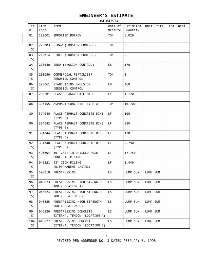
STATE OF CALIFORNIA-BUSINESS, TRANSPORTATION AND HOUSING AGENCY PETE WILSON, Governor DEPARTMENT OF TRANSPORTATIONESC/OE MS #43P.O. Box 942874SACRAMENTO, CA 94274-0001
TDD (916) 654-4014
Use Word 6.0c or later to
view Mac intosh pi cture .
April 15, 1998
04-CC,Sol-80-12.8/14.1,0.0/0.604-043934
Addendum No. 6
Dear Contractor:
This addendum is being issued to the contract for construction on State highway in CONTRA COSTA AND SOLANO COUNTIES AT CROCKETT AND IN VALLEJO FROM CUMMINGS SKYWAY OVERCROSSING TO CARQUINEZ BRIDGE TOLL PLAZA..
Submit bids for this work with the understanding and full consideration of this addendum. The revisions declared in this addendum are an essential part of the contract.
Bids for this work will be opened on April 29, 1998.
This addendum is being issued to revise the Project Plans, and the Notice to Contractors and Special Provisions.
Project Plan Sheets 161, 167, 171, 181, 210, 253, 259, 315, 319, 374 and 392 are revised. A half-sized copies of the revised sheets are attached for substitution for the like numbered sheets.
On Project Plan Sheets 21, 22, 23, 24 and 25 the reference to "Temporary Construction Easement" is deleted.
In the Special Provisions, Section 5-1.30, "Areas For Contractor's Use" the phrase "for storage of equipment or materials" is added to the end of the first sentence of the fourth paragraph.
In the Special Provisions, Section 5-1.30, "Areas For Contractor's Use" the following paragraph is added after the fourth paragraph:
“Temporary construction easements established for this project are as defined on the Materials Information handout, “ Right-of-Way Map, Appraisal A-1212.2,” dated March 1998.”
In the Special Provisions, Section 10-1.13, "Obstructions" Item No. 5 of the sixteenth paragraph is revised as follows:
"5. Install new pipeline in 30" casing jacked under railroad tracks between Pier 5 and Bent A13E. The earliest start date for this work is November 1, 1998."
In the Special Provisions, Section 10-1.13, "Obstructions" the seventeenth and eighteenth paragraphs are revised as follows:
"The Contractor shall make available to PG&E certain areas within the project limits for the work by PG&E. The work areas required by PG&E are generally as indicated in Table 1.
No work shall be done at Port Street, at Bents D5, D6, A10E, A11E, and A12E until the new underground gas pipeline has been installed and the old underground gas pipeline deactivated by PG&E. No work other than minor erection or preliminary removal operations shall be done on the west truss of the 1958 bridge, at Bent A13E, or at the west side of the north abutment until the old above-ground gas pipeline has been deactivated by PG&E, nor shall work other than minor erection work be done on the east truss, at Pier 5, or at the east side of the north abutment after the new above-ground pipeline has been activated by PG&E without the express written approval of the Engineer."
In the Special Provisions, Section 10-1.72A, "Pipe Support Installation Procedure" subsection "Requirements And Installation Prerequisites" the phrase "Item 1 of" is deleted from the tenth paragraph.

Addendum No. 6 04-CC,Sol-80-12.8/14.1,0.0/0.6Page 2 04-043934April 15, 1998
In the Special Provisions, Section 10-1.72A, , "Pipe Support Installation Procedure" subsection "Procedure" the phrase "(as described in Item 4 of the Procedure)" is deleted from the first paragraph.
In the Special Provisions, Section 10-1.72A, , "Pipe Support Installation Procedure" subsection "Procedure" the eighth paragraph is revised as follows:
"As soon as a pin is replaced with a bolt, the bolt shall be tightened to the tension values shown in Table 4 of "Specification for Structural Joints using ASTM A325 or A490 Bolts," approved by the Research Council on Structural Connections of the Engineering Foundation, Nov. 1985, and published in the American Institute of Steel Construction's "Manual of Steel Construction," Ninth Edition, 1989."
In the Special Provisions, Section 10-1.72A, , "Pipe Support Installation Procedure" subsection "Procedure" the phrase "in Item 8 of the Procedure" is deleted from the twelfth paragraph.
In the Special Provisions, Section 10-1.72A, , "Pipe Support Installation Procedure" subsection "Procedure" the seventeenth through twentieth paragraphs, inclusive, are revised as follows:
"MEASUREMENT AND PAYMENT
Attention is directed to the following which applies to Sections "Miscellaneous Metal (Bridge) and Pipe Support Installation Procedure" of these special provisions.
The second paragraph in Section 75-1.06, "Measurement," of the Standards Specifications is amended to read:
Scale weights will not be required when miscellaneous iron and steel, miscellaneous bridge metal, miscellaneous metal (restrainer), or pumping plant metal work are designated as final pay items in the Engineer's Estimate.
Full compensation for furnishing and installing a ladder safety post and safety climb device for each ladder, for providing a hold open device and spring assist on access doors shall be considered as included in the contract unit price paid per pound for miscellaneous metal bridge and no additional compensation will be allowed therefor.
The contract unit prices paid for the various types of miscellaneous metal pipe supports (bridge), entitled Pipe Support Detail 1 thru 9, shall include full compensation for furnishing all labor, materials, tools, equipment, and incidentals and for doing all the work involved in the various miscellaneous metal pipe supports (bridge), complete in place, including fabrication, installation and painting, as shown on the plans, as specified in the Standard Specifications and these special provisions, and as directed by the Engineer."
To Proposal and Contract book holders:
INDICATE RECEIPT OF THIS ADDENDUM BY FILLING IN THE NUMBER OF THIS ADDENDUM IN THE SPACE PROVIDED ON THE SIGNATURE PAGE OF THE PROPOSAL.
PROVIDE A COPY OF THE INFORMATIONAL HANDOUT AS ATTACHED
Submit bids in the Proposal and Contract book you now possess. Holders who have already mailed their book will be contacted to arrange for the return of their book.
Inform subcontractors and suppliers as necessary.

Addendum No. 6 04-CC,Sol-80-12.8/14.1,0.0/0.6Page 3 04-043934April 15, 1998
This office is sending this addendum by UPS overnight mail to Proposal and Contract book holders to ensure that each receives it.
If you are not a Proposal and Contract book holder, but request a book to bid on this project, you must comply with the requirements of this letter before submitting your bid.
Sincerely,
ORIGINAL SIGNED BY
NICK YAMBAO, ChiefPlans, Specifications &Estimates BranchOffice of Office Engineer
Attachments

STATE OF CALIFORNIA-BUSINESS, TRANSPORTATION AND HOUSING AGENCY PETE WILSON, Governor DEPARTMENT OF TRANSPORTATIONESC/OE MS #43P.O. Box 942874SACRAMENTO, CA 94274-0001
TDD (916) 654-4014
Use Word 6.0c or later to
view Mac intosh pi cture .
April 21, 1998
04-CC,Sol-80-12.8/14.1,0.0/0.604-043934
Addendum No.7
Dear Contractor:
This addendum is being issued to the contract for construction on State highway in CONTRA COSTA AND SOLANO COUNTIES AT CROCKETT AND IN VALLEJO FROM CUMMINGS SKYWAY OVERCROSSING TO CARQUINEZ BRIDGE TOLL PLAZA..
Submit bids for this work with the understanding and full consideration of this addendum. The revisions declared in this addendum are an essential part of the contract.
Bids for this work will be opened on April 29, 1998.
This addendum is being issued to revise the Notice to Contractors and Special Provisions and the Engineer's Estimate.
In the Special Provisions, Section 13-2, "Railroad Protective Insurance" the seventh paragraph is revised as follows:
"The approximate ratio of the estimated cost of the work over or under or within 50 feet of Railroad's tracks to the total estimated cost is 0.07. Approximate daily train traffic is 60 passenger trains and 5 freight trains."
In the "Copy of Engineer's Estimate" in the NOTICE TO CONTRACTORS and the "Engineer's Estimate" in the PROPOSAL, Item 70 is revised and Item 211 is deleted as attached.
To Proposal and Contract book holders:
REPLACE PAGES 6 AND 13 OF THE ENGINEER'S ESTIMATE IN THE PROPOSAL WITH THE ATTACHED REVISED PAGES 6 AND 13 OF THE ENGINEER'S ESTIMATE. THE REVISED ENGINEER'S ESTIMATE IS TO BE USED IN THE BID SUBMITTAL AND INSERTED IN THE PROPOSAL.
INDICATE RECEIPT OF THIS ADDENDUM BY FILLING IN THE NUMBER OF THIS ADDENDUM IN THE SPACE PROVIDED ON THE SIGNATURE PAGE OF THE PROPOSAL.
Submit bids in the Proposal and Contract book you now possess. Holders who have already mailed their book will be contacted to arrange for the return of their book.
Inform subcontractors and suppliers as necessary.
This office is sending this addendum by (confirmed facsimile to all book holders to ensure that each receives it.
If you are not a Proposal and Contract book holder, but request a book to bid on this project, you must comply with the requirements of this letter before submitting your bid.
Sincerely,
ORIGINAL SIGNED BY
NICK YAMBAO, ChiefPlans, Specifications &Estimates BranchOffice of Office Engineer
Attachments

ENGINEER'S ESTIMATE04-043934
Item Item Code
Item Unit of Measure
Estimated Quantity
Unit Price Item Total
61(S)
159104 RAISE BRIDGE, LOCATION C LS LUMP SUM LUMP SUM
62 160101 CLEARING AND GRUBBING LS LUMP SUM LUMP SUM
63 170101 DEVELOP WATER SUPPLY LS LUMP SUM LUMP SUM
64 190101 ROADWAY EXCAVATION CY 2,250
65 011318 ROADWAY EXCAVATION (HAZARDOUS MATERIAL)
CY 3,180
66 011319 DRAINAGE EXCAVATION (HAZARDOUS)
CY 1,350
67(S)
011320 SANITARY SEWER EXCAVATION (HAZARDOUS)
CY 500
68(F)
192003 STRUCTURE EXCAVATION (BRIDGE)
CY 832
69(S)
011916 WATER CONTROL LS LUMP SUM LUMP SUM
70(F)
047079 STRUCTURE EXCAVATION (CONTAMINATED)
CY 1,598
71(F)
192021 STRUCTURE EXCAVATION (TYPE DH)
CY 3,035
72(F)
192023 STRUCTURE EXCAVATION (TYPE H)
CY 2,145
73(S-F)
011321 STRUCTURE EXCAVATION (RETAINING WALL, TYPE H)
CY 370
74(F)
193003 STRUCTURE BACKFILL (BRIDGE) CY 2,141
75(S-F)
193013 STRUCTURE BACKFILL (RETAINING WALL)
CY 280
76 011322 DRAINAGE BACKFILL(CLASS 3 AB) CY 820
77 011323 DRAINAGE BACKFILL (IMPORTED BORROW)
CY 910
78(S)
011324 SANITARY SEWER BACKFILL (CLASS 3 AB)
CY 140
79(S)
011325 SANITARY SEWER BACKFILL (IMPORTED BORROW)
CY 250
80 193114 SAND BACKFILL CY 34
6REVISED PER ADDENDUM NO. 7 DATED APRIL 21, 1998

ENGINEER'S ESTIMATE04-043934
Item Item Code
Item Unit of Measure
Estimated Quantity
Unit Price Item Total
201(S)
011332 SIGNAL AND LIGHTING (STAGE CONSTRUCTION- LOCATION 2)
LS LUMP SUM LUMP SUM
202(S)
861504 MODIFY LIGHTING AND SIGN ILLUMINATION
LS LUMP SUM LUMP SUM
203(S)
047001 SEISMIC MONITORING SYSTEM LS LUMP SUM LUMP SUM
204 046846 INSTALL SEISMIC MONITORING CASING (DOWNHOLE)
LF 225
205 011914 TIME RELATED OVERHEAD WDAY 780
206 012415 ROADWAY EXCAVATION (CONTAMINATION MATERIAL)
CY 2,130
207 012416 DRAINAGE EXCAVATION (CONTAMINATED)
CY 890
208 012417 SANITARY SEWER EXCAVATION(CONTAMINATED)
CY 190
209 012419 MISCELLANEOUS METAL(PIPE SUPPORT DETAIL 8)
EA 2
210 012420 MISCELLANEOUS METAL(PIPE SUPPORT DETAIL 9)
EA 1
211 BLANK
212 999990 MOBILIZATION LS LUMP SUM LUMP SUM
TOTAL BID:
13REVISED PER ADDENDUM NO. 7 DATED APRIL 21, 1998

STATE OF CALIFORNIA-BUSINESS, TRANSPORTATION AND HOUSING AGENCY PETE WILSON, Governor DEPARTMENT OF TRANSPORTATIONESC/OE MS #43P.O. Box 942874SACRAMENTO, CA 94274-0001
TDD (916) 654-4014
Use Word 6.0c or later to
view Mac intosh pi cture .
April 24, 1998
04-CC,Sol-80-12.8/14.1,0.0/0.604-043934
Addendum No. 8
Dear Contractor:
This addendum is being issued to the contract for construction on State highway in CONTRA COSTA AND SOLANO COUNTIES AT CROCKETT AND IN VALLEJO FROM CUMMINGS SKYWAY OVERCROSSING TO CARQUINEZ BRIDGE TOLL PLAZA..
Submit bids for this work with the understanding and full consideration of this addendum. The revisions declared in this addendum are an essential part of the contract.
Bids for this work will be opened April 29, 1998.
This addendum is being issued to revise the Notice to Contractors and Special Provisions and the Engineer's Estimate.
In the Special Provisions, Section 5-1.19, "Payments" the item "Electronic Mobile Daily Diary Computer System" $170,000 is deleted.
In the Special Provisions, Section 10-1.11, "Electronic Mobile Daily Diary Computer System" is deleted.
In the Special Provisions, Section 10-1.12, "Electronic Mobile Daily Diary System Data Delivery" the third paragraph is revised as follows:
“This personnel information will only be used with a State mobile daily diary computer system and it will not relieve the Contractor and subcontractors from all the payroll records requirements as required by Section 7-1.01A(3), "Payroll Records," of the Standard Specifications.”
In the Special Provisions, Section 10-1.13, "Obstructions" the following paragraph is added after the tenth paragraph:
"The earliest start date for any work in the California & Hawaiian Sugar Company, Inc., a Hawaii Corporation Lessee property, shall be August 29, 1998, as shown on the information handout, "Right-of-Way Map, Appraisal A-1212", dated March 1998."
In the Special Provisions, Section 10-1.60, "Steel Structures" the following paragraphs are added after the last paragraph:
"MEASUREMENT AND PAYMENT.--Measurement and payment for steel structures shall conform to the provisions in Sections 55-4.01, "Measurement," and 55-4.02, "Payment," of the Standard Specifications and these special provisions.
The sixth paragraph in Section 55-4.02, "Payment," of the Standard Specifications is amended to read:
If a portion or all of the welded structural steel is fabricated more than 300 air line miles from both Sacramento and Los Angeles, additional shop inspection expenses will be sustained by the State. Whereas it is and will be impracticable and extremely difficult to ascertain and determine the actual increase in such expenses, it is agreed that payment to the Contractor for furnishing said structural steel from each fabrication site located more than 300 air line miles from both Sacramento and Los Angeles will be reduced $5,000 or by an amount computed at $0.020 per pound of structural steel fabricated, whichever is greater, or in the case of each fabrication site located more than

3,000 air line miles from both Sacramento and Los Angeles, payment will be reduced $8,000 or by $0.036 per pound of structural steel fabricated, whichever is greater.

Addendum No. 8 04-CC,Sol-80-12.8/14.1,0.0/0.6Page 2 04-043934April 24, 1998
If a portion or all of check samples are removed at a mill more than 300 air line miles from both Sacramento and Los Angeles, shop inspection expenses will be sustained by the State which are in addition to expenses incurred for fabrication site inspection. Payment to the Contractor for furnishing structural steel will be reduced $2,000 for each mill located more than 300 air lines miles from both Sacramento and Los Angeles.
The first paragraph in Section 55-4.01, "Measurement," of the Standard Specifications is amended to include the following subparagraph:
H. No allowance will be made for the weight of backing bars in computing the weights of metal to be paid for.
The second paragraph in Section 55-4.02, "Payment," of the Standard Specifications is amended to read:
The contract price paid per pound for furnish structural steel (bridge) shall include full compensation for furnishing all labor, materials, tools, equipment and incidentals, and for doing all the work involved in furnishing, fabricating and delivering structural steel to the jobsite, ready for erection, including furnishing those bolts, nuts and washers which do not replace rivets, stud connectors (except where paid for in “Install Stud Connectors”), welding materials, requalifying welders specifically for this project, backing bars, elastomeric bearing pads(except the 18” thick elastomeric pads at the bases of towers 2 and 4 on the “A4E” Mainspan), or other materials required for erection and connection or splicing of the structural steel; galvanizing the structural steel when galvanizing is required by the specifications or plans; and conforming to the qualification and testing requirements associated with member fabrication; as shown on the plans, as specified in the Standard Specifications and these special provisions, and as directed by the Engineer.
The third paragraph in Section 55-4.02, "Payment," of the Standard Specifications is amended to read:
The contract price paid per pound for erect structural steel (bridge) shall include full compensation for furnishing all labor, materials, tools, equipment and incidentals, and for doing all the work involved in erecting the structural steel, complete in place, including temporary shoring for x-bracing, top and bottom laterals, sway frames, portal frames, hold downs, and tower and other components during erection of new structural elements; drilling new bolt holes in existing steel, connecting and splicing the structural steel; placing asbestos sheet packing, performed fabric pads and elastomeric bearing pads; furnishing and applying caulk; furnishing and placing mortar for masonry or bearing plates and anchor bolts; checking bolt tension; conforming to qualification and testing requirements associated with member erection, connection or splicing; and submitting the structural steel erection plan, as shown on the plans, as specified in the Standard Specifications and these special provisions, and as directed by the Engineer.
The contract price paid per pound for remove structural steel shall include full compensation for
furnishing all labor, materials, tools, equipment and incidentals, and for doing all work involved in removing existing steel superstructure and tower components, rocker bearings and other structural elements, including the existing wind locks and truss hold-down pins at Abutment 1 and Pier 5 of the “A4E” Main Span, bolts, nuts and washers (but excluding rivets and bolts paid for under “Remove Bolt or Replace Rivet”) as shown on the plans, as specified in the Standard Specifications and these special provisions, and as directed by the Engineer.
Work under remove structural steel shall also include temporary removal, storage, and restoration of miscellaneous existing facilities attached to structural steel being removed.
Full compensation for temporary removal, storage and restoration of miscellaneous existing facilities attached to structural steel to be removed shall be considered as included in the contract unit price paid for remove structural steel, and no additional compensation will be allowed therefor.

Addendum No. 8 04-CC,Sol-80-12.8/14.1,0.0/0.6Page 3 04-043934April 24, 1998
Full compensation for any temporary bracing, shoring or falsework in connection with structural steel removal, as shown on the plans, as may be determined necessary by the Contractor, or as directed by the Engineer shall be considered as included in the contract unit price paid per pound for remove structural steel, and no additional compensation will be allowed therefor.
Full compensation for preparing and submitting a structural steel removal plan, as specified in these special provisions, shall be considered as included in the contract unit price paid per pound for structural steel removal, and no additional compensation will be allowed therefor."
In the "Copy of Engineer's Estimate" in the NOTICE TO CONTRACTORS and the "Engineer's Estimate" in the PROPOSAL, Item 10 is deleted as attached.
To Proposal and Contract book holders:
REPLACE PAGE 3 OF THE) ENGINEER'S ESTIMATE IN THE PROPOSAL WITH THE ATTACHED REVISED PAGE 3 OF THE ENGINEER'S ESTIMATE. THE REVISED ENGINEER'S ESTIMATE IS TO BE USED IN THE BID SUBMITTAL AND INSERTED IN THE PROPOSAL.
A COPY OF CONTRACTOR'S INQUIRY RESPONSES NO. 1, 2 AND 3 DATED APRIL 23, 1998 IS ADDED AS ATTACHED.
INDICATE RECEIPT OF THIS ADDENDUM BY FILLING IN THE NUMBER OF THIS ADDENDUM IN THE SPACE PROVIDED ON THE SIGNATURE PAGE OF THE PROPOSAL.
Submit bids in the Proposal and Contract book you now possess. Holders who have already mailed their book will be contacted to arrange for the return of their book.
Inform subcontractors and suppliers as necessary.
This office is sending this addendum by confirmed facsimile to Proposal and Contract book holders to ensure that each receives it.
If you are not a Proposal and Contract book holder, but request a book to bid on this project, you must comply with the requirements of this letter before submitting your bid.
Sincerely,
ORIGINAL SIGNED BY
NICK YAMBAO, ChiefPlans, Specifications &Estimates BranchOffice of Office Engineer
Attachments

04-043934
CONTRACTOR'S INQUIRY RESPONSES NO. 1,2 & 3APRIL 23, 1998
1) CALTRANS TOLL BRIDGE RETROFIT PROGRAM ADDRESS
The Caltrans District 4 Office is located at 111 Grand Avenue, Oakland, Ca 94612. The mailing address isP.O. Box 23660, Oakland, Ca 94623-0660. The Toll Bridge Retrofit Duty Senior telephone number is (510)286-5549, and the fax number for Contractor's inquiries submittals is (510) 286-4563
2) Would contract plan electronic files be available to contractor?
Contract plan electronic files will not be available to Contractors.
3) Coastwise trade determination for qualified barges.
"A non-coastwise qualified barge may be used as a moored stationary work platform within the territorial waters of the United States without violating the coastwise laws, provided that it transport neither passengers nor merchandise while under tow between coastwise points." Contractors have to get all the appropriate permits from the US Coast Guard.
4) Does the worker's compensation insurance for this project fall under the jurisdiction of the United States Longshore and Harbor Worker Act/or the Jones Act?
The Jones Act (46 U.S.C. & 13 et seq.) applies to seamen and shipping and does not relate to construction workers on the bridge. The Longshore and Harbor Workers' Compensation Act (33 U.S.C. & 901 et seq.) applies to employees engaged in maritime employment. A federal court decision of the Fourth Circuit Court of Appeals has held that a construction worker employment in building a bridge over navigable water, designed to benefit both traffic and navigation, is engaged in maritime employment under the Longshore and
Harbor Workers' Compensation Act. (LeMelle v. B.F. Diamond Const. Co.)(1982) (674 Fed2.d 296). Under California law (Lab. Code & 3700), every employer is responsible for being insured against liability to pay workers' compensation. That responsibility is incorporated into the Department of Transportation's (Department) construction contracts under the provisions of the Standard Specifications Section 7-1.01(A)(6) that requires the construction contractor to certify compliance with Labor Code Section 3700.
5) Section 5.1-37 requires two working boats be provided and operated for the duration of the contract. Will Caltrans require the boat operator and crew members for these boats to work a full ten hour day for each working day of the contract, including Saturday, Sundays, and holidays? Will the boat crews be required if the Contractor is not actually working a particular Saturday or Sunday?
The Contractor shall provide the boats and crews for every day that the Contractor is scheduled to work including Saturdays, Sundays, and Legal Holidays.
6) Please reference Contract Specification Section 4. it is stated that the contract duration is 400 working days, which includes Saturdays, Sundays, Legal Holidays and inclement weather days. Even if the Contractor was to work multiple shifts the job would be impossible to complete on time. Will Caltrans consider extending the time of completion to a more realistic time frame, similar to the other seismic retrofit jobs (i.e. Benicia-Martinez = 825 days, San Mateo-Hayward = 760 days).
See Addendum No 1. to be issued soon.
7) The contract specifications states that all retrofit work on the outside face of the East truss must be done prior to moving the 26" gas main and prior to starting work on the outside face of the west truss. PG&E is then given six weeks or 11 % of the job duration to relocate the gas line. To work efficiently the Contractor must work both faces of a truss at the same time. Can PG&E's schedule be shortened by multiple shifts, etc. to give the Contractor more time to do this work?
No.
CONTRACT NO. 04-043934ADDED PER ADDENDUM NO. 8 DATED APRIL 24, 1998

8) Can Work be on-going on either truss outside face during the 26" gas line relocation?
No.
9) Is the 26" gas line always active during the course of the job?
Yes.
10) The "Remarks" on page 84 of the Special Provisions state that "All lanes on the Eastbound Carquinez Bridge may be closed between 12:30 AM and 4:00 AM, Tuesdays and Thursdays only....", while the Lane Closure Charts on pages 84 & 85 show that a minimum of 2 (two) adjacent traffic lanes, both directions, shall be open for use by public traffic by 3:00 AM, Monday through Thursday. Other clauses contained in the Special Provisions impose restrictions whereby if 2 (two) Westbound lanes are open to traffic, the third lane cannot be used by public traffic traveling Eastbound.
Lane Closure Charts show only 1 lane required for eastbound and 1 lane for Westbound needed between 3:00 AM - 4:00 AM on weekdays. All lanes on the Eastbound Carquinez Bridge may be closed between 12:30 AM to 4:00 AM, Tuesday and Thursday only....,". This can only be done when a Eastbound lane is detoured onto the Westbound bridge as shown on sheet SC - 3. When two-way traffic is required on the Westbound Carquinez Bridge, a buffer lane is required to separate Westbound and Eastbound traffic. The
clauses in the Special Provisions imposing restrictions on the Westbound lanes when the Eastbound lane is on the Westbound bridge are correct.
11) Section 10 -1.01 of the Special Provisions (Order of Work), states that the trestle and cofferdam at Pier # 5 must be completed by 3 - 31 - 98. Due to the Delta Smelt problem this looks improbable due to: a) With a 2 - 18 - 98 bid date and 10 days award, work would commence the 1st or 2nd week in March. b) A (30) to (12) weekly review of Cofferdam design (Section 10-1.31). c) Dredging permit required (Section 10-1.31E) to remove in place rip rap before the cofferdam work can start. A dredging plan approval takes 30 days. d) SWPPP plan needs to be submitted and approved before any work can start (Section 10-1.02). e) As the pier #5 retrofit must be completed before the 26" dia. Gas line can be relocated (Section 10-1.13, table 1), please clarify how this will occur with the existing parameters.
See Addendum # 2 for contract time extension, and deletion of the requirement for any cofferdam and trestle work to be completed by 3-31-98.
12) Can the contractor utilize the old pier piles on the West side of Pier no. 5 (in side R/W) for barge access?
The Contractor must do all the work within the terms and conditions of permits issued by the regulatory agencies. These permits are available to the Contractors during the bid period. Caltrans has not discussed the use of the old pilings with any of the regulatory agencies during the permitting process, however, the piles are located within the shallow waters and agencies are likely to be concerned if there will be any disturbances
to fish habitat between March 31 and December 1.
13) Refering to Section 10 - 1.31D, can water be pumped from one excavation to another.
Pumping from one excavation to another is acceptable. The intent is to minimize the amount of water requiring treatment.
14) Can dirt be imported and placed adjacent ot Pier no. 5 ( in non-BSA areas ) for access.
The Contractor must do work whithin the terms and conditions of permits issued by the regulatory agencies. These permits are available to the Contractors during the bid period. We do not believe that placing dirt at this location is consistent with all permit requirements.
CONTRACT NO. 04-043934ADDED PER ADDENDUM NO. 8 DATED APRIL 24, 1998

15) Reference Special Provision Section 10-1.31, "EARTHWORK" "At locations where structure excavation Type C or Type DH is shown on the plans, backfill will be measured and paid for as structure backfill in conformance with the requirements of Section 19-3.06, "Structure Backfill," of the Standard Specifications, except at Pier 5 on the "A4E" Line where backfill shall consist of non-hazardous soil which is free of organic material, trash or other unsatisfactory material." Does this mean we can use the structure excavation Type DH and Type H materials as Structure Backfill, except at Pier 5? If the hazardous material is tested or treated and the amount of lead is within the allowable limits, can it be used as Structure Backfill?
No
16) Reference Special Provision Section 10-1.17, "MAINTAINING TRAFFIC," Lane closure charts No. 1 & 2 Remarks "All lanes on the Eastbound Carquinez Bridge may be closed between 12:30 AM and 4:00 AM, Tuesdays and Thursdays only, for the duration of the project and as approved by the Engineer, when required in the interests of public safety." Bid item 14 - TRAFFIC CONTROL (CROSSOVER DETOUR) has a quantity for item 14 need to be adjusted or can we use the crossover detour at other times during the project?
400 Working Days as originally specified in the Special Provisions translates into 80 weeks X 2 times/week = 160 uses of the crossover detour. The crossover detour will NOT be available for the Contractor to use at other times. Be advised that Addendum #2 changes the number of working days and the definition of the working day.
17) Section 10-1.28 indicates that the paint removal debris must be disposed at a Class 1 landfill selected by the Contractor. This section is silent on who will be considered the generator of this material. We are assuming that the State is the generator. Please confirm this assumption.
The State will be considered the generator for the paint removal debris. The Engineer will be responsible for signing all the shipping manifests.
18) We are requesting the following materials information handouts referenced in the Special Provisions but not included in the bid package: a. "Existing Bridge Utilities and Maintenance equipment on Eastbound (1958) Carquinez Bridge. Called out on page 77 (SP). b. Regarding Sources of water for use. c. Hazardous Materials. Called out on page 32 (SP).
All of the referenced materials handouts are available for the Contractor's review at the Toll Bridge Program Duty Senior's desk and are not available by mail.
19) We are requesting Caltrans Record Drawing #300-07-04 for utilities details not shown on the plans. This is called out on Note #3 on plan sheet 48/555.
The record drawing #300-07-04 is included in the materials handout "Existing Bridge Utilities and Maintenance Equipment on the Eastbound (1958) Carquinez Bridge" which is available for review at the Toll Bridge Duty Senior's desk.
20) Please provide us with the list of STD manufacturers referred in Section 10-1.71, "Shock Transmission Devices."
See Addendum # 2.
21) The existing sewer line interferes with pier # 5.
The existing line will be abandoned. There is no conflict with the new sanitary line in the vicinity of pier #5.
22) Would you clarify how contaminated the material in item "Structure Excavation (Contaminated) is?
See Addendum # 3 for clarification.
CONTRACT NO. 04-043934ADDED PER ADDENDUM NO. 8 DATED APRIL 24, 1998

23) Since the Type D item has been eliminated, will the "Structure Backfill," item be increased?
Structure excavation (Type D) has been eliminated. Structure backfill has no changes. See Addendum #3 for more information.
24) What is the level and depth of hazardous material at abutment #1 and pier #5 on the main line.
See Addendum #3 for clarification.
25) Is the CIDH (30"x 48") soil also contaminated?
See Addendum #3.
26) Is there a Buy America Requirement for this job? Is there a Buy America Requirement for this job?
There are no Buy America Requirements for this job.
27) The following Questions apply to section 10-1.71 Shock Transmission Devices a)In regards to Part 1 Manufacturer's Data Package STD Assembly Drawing - I am not clear as to the exact Caltrans Definition of the term "Assembly Drawing", could you please give clarification on the exact level of detail required for these drawings to allow us to produce them to meet the requirements?
The STD assembly drawing is a working drawing that details the components of the STD drawn at a reasonable scale on 60 pound bond paper either 11" x 17" or 22" x 34" as stated in the subsection entitled "Submittals and Working Drawings". The level of detail should be such that Caltrans as owners could identify all the parts of the STD by name, function, size and scale. The working drawings will be helpful in the inspection and testing. Detailed manufacturing drawings need not be submitted. Also refer to Section 10-1.71, Subsection "STD Assembly Drawing."
b)What is the intended time of installation of the STD's? I cannot see from the drawings, or from Section 10-1.01 Order of Work the exact proposed timings?
The installation of the devices on the east side will be completed before the relocation of the gas line from the west side to the east side. Installation of the devices on the west side of the bridge will not begin until after the gas line is relocated.
c)Drawing sheet "A4E Line (Main Span) Structure Plan No. 3 shows the identifier "A12" for the STD Retrofit in the Retrofit legend. I have identified the position of "A12" on the drawing sheets "A4E" Line (Main Span) on Structure Plan No. 1 and 5 and the expansion joints on the bottom chord of the trusses, but I do not see an "A12" on Structure Plan No. 1 at pier 5 for the other location. Have I identified the locations on the plans correctly? I infer from the detail drawings that there are two STD's at each of the three locations?
The Connection details for the Shock Transmission device are shown on sheet 253 of the Contract Plans. Please note that The exterior gusset is shown and the interior gusset is similar See note 1. Also see note 8 as location L29 is shown and location L86 is similar. The other remaining STD's are at pier 5 on sheet 195. There are two Shock transmission units at each location for a total of six to be installed. The specifications call for a spare or seventh STD to be delivered to the maintenance shop.
CONTRACT NO. 04-043934ADDED PER ADDENDUM NO. 8 DATED APRIL 24, 1998

d) Are all seven STD's to have the same external configuration? This question has arisen in my mind while looking at Drawing sheets "A4E" Line (Main Span): Pier No. 5 - Sections No. 3 and Truss Details L29 No 1. Note 11 on sheet 253 states that the device shall not protrude more than 6" below the existing structure (from the relevant sections and details) I determine this gives an overall envelope radius of around 2'- 7". However as far as I can see, the Pier No. 5-Sections No.3 drawing sheet shows a limiting radius dimension of around 1'-6" where the STD is adjacent to the welded housing/support for the RH (West) connection of the STD to the bridge. The SSTD is of course oriented 90 degree in the two different locations and this may alleviate the problem. Please could I have information on the exact external physical envelope available into which to fit the STD?
All Shock Transmission Devices shall have the same external dimensions, so the spare unit may be substituted for any of the six installed units.
e) After our initial design checks we are a little concerned with the steel plate thickness of the cheek plates shown on Drawing Sheet "A4E" Line (MainSpan) Pier No. 5 - Details No. 2. Please could I have information on the design philosophy behind the welded housing/support for the RH (West) connection of the STD (s?) to the bridge at pier 5?
The connection of the shock transmission device to the welded assembly is through a pin. The pin hole and welded assembly is designed in accordance with AASHTO LFRD Bridge Design Specifications, 1994 Edition, Section 6.8.7, "Pin-Connected Plates".
28) Contract Specification 10-1.64 Clean and Paint Structural Steel - Measurement and Payment indicates that spot blasting and undercoat painting will be measured and paid by the square foot, while Item 145 (S-F) indicates the item to be a final pay item.
a) Will Item 145 be paid on a unit cost basis for each square foot spot blasted and undercoat painted?
Spot Blast Clean and Undercoat is a final pay item paid per square foot.
b)What are the cleaning requirements outside of the faying surface area between new and existing steel surfaces? I.e. Does the steel get cleaned 6" past each faying surface as is the case with cleaning weld lines?
Only the faying surfaces require cleaning and undercoating. There is no requirement to clean outside of the faying surfaces. To obtain cleaning over the full contact area, cleaning beyond the contact area may be required. However, quantities are based on the contact surface area only.
29) We refer you to sheet 176 of 555 of the contract drawings. Under what bid item does the installation of the prestressing strands to anchor the steel anchor beams at pier 3 get paid?
Installation of prestressing strands at Pier 3 are paid under Item 95. Item Code 500010
30) We refer you to sheet 157 of 555 of the contract drawings; support beam detail. How can the contractor install the line of bolts where the nut is situated inside the beam?
Nuts inside the support beam must be placed before closing the support beam. The designer suggests trapping the nuts in place.
31) We refer you to sheet 471 of 555 of the contract drawings: Under what item does the coring and the installation of the H.S. Rods for the column casings get paid?
Installation of HS rods on approach span column casings is paid under items 96 and 97, Codes 046823 and 046824 respectively. Coring and pressure grouting of holes for HS rods is paid under items 116 to 120, Codes 046830 to 046834 respectively, depending on core diameter.
CONTRACT NO. 04-043934ADDED PER ADDENDUM NO. 8 DATED APRIL 24, 1998

32) Are the bearing pads for the approach structures to be bonded to the masonry and sole plates?
The bearing pads do not need to be vulcanized to the plates.
33) As the pier 5 retrofit must be completed before the 26" diameter gas main can be relocated (Section 10-1.13, table 2), please clarify how this work will be occur with these parameters?
SEE ADDENDUM NO. 5 for minor erection work over the gas line provided a protective cover is built over the gas line. Please see addendum for specifics.
34) Referencing Detail A and Section B-B of sheet 315 of 555. Section B-B calls for two rows of rivets to be removed. Notes and quantities shown on the Bottom Lateral Bracing Drawing seems to refer to the existence of only one(1) row of rivets. Detail example: Plan-Outside Connection Upper Gusset on Sheet 304 of 555, draws our attention to note 4 - See detail A on "Bottom Lateral Bracing Details" sheet, but the called out rivet quantity (6) only reflects the number of rivets found in a single row. Please clarify.
Section B-B from Detail A shown on sheet 315 of 555 ("Bottom lateral Bracing Details") is clarified as follows. The leader pointing from the note "Remove existing rivets (>2 ply) and install HS bolts (A325X)" should only point to the lower row, instead of both the upper and lower rows, The "As-Built" condition is rivets in the lower row, bolts in the upper row.
35) Reference Special Provisions Section 10-1.47: High Strength Threaded Rods to be grouted into cored holes will be paid for as Miscellaneous Metal (Bridge). Please confirm bearing plates and nuts will also be paid for as "Miscellaneous Metal (Bridge)". Please note that Special Provision Section 10-1.72 does not identify the above items as being involved in that pay item.
The second paragraph of Section 75-1.02 of the Standard Specifications lists threaded rods as Miscellaneous Iron and Steel items which conform to ASTM A 307 and for high strength ASTM A 449. The first paragraph of Section 75-1.03 references Miscellaneous Metal Bridge back to Section 75-1.02. Therefore the Threaded rods pressure grouted in cored holes and the plates and nuts attached to them shall be paid as "Miscellaneous
Metal Bridge" per the special provisions and the Standard Specifications.
36) On sheet 319 of 555 (Shear Lock Elevation - Piers 2 & 4). Designer shows an upset rod with 6-1/2" dieter ends (Detail B) installed in 6" diameter hole (Section A-A). If the the 6-1/2" dimension holds is there enough room?
The hole for the upset rods should be increased to 6-5/8" diameter.
37) Will Caltrans consider allowing Contractors to use the existing air supply on the bridge if it is boosted?
The specifications require that Contractors supply their own air supplies.
38) The Contract Specifications State that all retrofit work on the outside face of the east truss must be completed before moving the 26" diameter gas main and before starting work on the outside face of the west truss. Please define the members consisting of the outside face of the truss.
The West Face is defined as the connections at and the members between the "L", "ML", "MM", "M", "MU" and "U" JOINTS ON THE WESTERN SIDE OF THE BRIDGE. This restriction prevents working over the active gas line, which could be damaged by falling materials. Currently an addendum is being issued to allow minor erection work over the gas line. See addendum for requirements.
CONTRACT NO. 04-043934ADDED PER ADDENDUM NO. 8 DATED APRIL 24, 1998

39) Section 10-1.64 "Clean and Paint Structural Steel" of the Contract Specifications states that "at locations where stiffeners are added to the existing steel members without the removal of any existing steel, the existing steel area below the stiffeners need not be dry blast cleaned but shall be steam cleaned.". Based on this statement, can we assume that the existing area below the new stiffener angles (on the top/bottom chords, truss, and on gussets) need not be dry blast cleaned?
Angles which are added to members without removing any existing steel do not require dry blast cleaning, except where required to be slip critical as noted by "A325SC" on the plans. In this case the clean and paint provisions specific to slip critical bolting apply.
40) Reference Specification section 10-1.71, Shock Transmission Devices, Section 3, Execution. The Contractor is asked to submit "Ten copies of the Qualification Data Package....with the Contractor's bid." Each copy of this data is in a one and one half inch three ring binder. ten copies would make a substantial size bid package. Due to the size of this documentation could we submit one copy at bid time and the remaining nine copies to follow for the low three bidders?
See Addendum No. 5
41) Reference Plan Sheet 140- "QUANTITIES AND GENERAL NOTES". On the "A4E" Line (Main Span) the quantity for Structure Concrete, Bridge is shown as 3,900 cy and Structure Concrete Bridge Footing is 860 cy. After completing a take-off on Structure Concrete, Bridge my quantity is 860 cy less than what is shown on the plans. I would like you to check if maybe the Structure Concrete, Bridge Footing was added to the Structure Concrete, Bridge by mistake. Please check?
The quantities have been reviewed and there have not been any errors found. The quantities are taken off by two individual estimators and both calculations were found within the acceptable limits. Quantity calculation
and quantity check calculations validate the 3,892 cy quantity of Structural Concrete, Bridge, and 860 cy of Structural Concrete, Bridge Footing for the A4E-Line Main Span.
42) Reference Plan Sheet 436- INDEX TO PLANS On the "A4E" Line (Approach Span) the quantity for Structure Concrete, Bridge is shown as 1,880 cy. After completing a take-off on the Structure Concrete, Bridge my quantity is greater than what is shown on the plans. I believe the concrete at Abutment 2 may have been left out of the 1,880 cy shown on the plans. Please check?
Quantities calculation and quantity check calculation validate the 1877 cy quantity of Structural Concrete, Bridge for the A4E-Line Approach.
43) On page 181 of the Special Provisions, it states "At locations where stiffeners are added to existing steel members without the removal of any existing steel area below the stiffeners need not be dry blast cleaned but shall be steam cleaned in accordance with Section 59-2.05. "Steam Cleaning," of the Standard Specifications." As a representative example, note the runs of angle shown below on a portion of the Design Drawing (page 244 of 555) found at location M17. Please confirm that the angles used to strengthen existing members, such as the example shown at the M17-M18 member do not have to be dry blast cleaned.
Angles attached to members or along the free edges of gusset plates that do not have any slip critical bolts may receive steam cleaning only, dry blast cleaning is not required. Where an angle or plate has any slip critical bolts, the existing surface under the entire angle or plate shall receive dry blast cleaning.
44) Special Provisions Section 10-1.28A refers to As-Built Plans for wooden stairs shown on sheets entitled "East Carquinez Bridge, maintenance Safety Improvements - walkway and stairway at Abutment No. 1". We are requesting a copy of these plans.
All as-built plans are available at the District Toll Bridge Duty Senior's Office. Contact Yader Bermudez by phone @ (510) 286-5549 for information.
CONTRACT NO. 04-043934ADDED PER ADDENDUM NO. 8 DATED APRIL 24, 1998

45) On page 97 of the Special Provisions regarding the Maintenance Travelers being unsafe. What is unsafe about the travelers in their current condition?
The travelers are reported to have been constructed with aluminum components connected with structural steel bolts. Corrosion between the two materials has degraded the connections to the point that they are unsafe and are no longer used by the state. No representation is made regarding the condition or suitability of other portions of the travelers.
46) Reference Plan Sheet 149 of 555, Section A-A, Stage 3, Sequence note #4: "Provide temporary cover opening resulting from removed finger joint"... Is this temporary cover (Steel Plate?) to be paid for as incidental item 29 (Salvage & Reinstall Structural Element) or item #5 (Temporary Bridge Decking).
Temporary cover to span over the removed finger joint may be a steel plate and shall be paid as incidental to "Temporary Bridge Decking".
47) What provisions are there in the contract to cover up the open excavation formed by drilling for the CIDH piles or precast abutment cap?
Standard Specification 7-1.09, Public Safety, governs open excavation protection.
48) Reference drawing sheet 161 of 555, (Pier #2-Top Plan).... the nearest reference dimensions at Section E-E, are 2'-1" and 5'-1". The corresponding dimension shown on Section E-E, sheet 164 of 555, (Pier #2 Sections) is 6'-9". Please confirm the accuracy of these dimensions and clarify their correlation.
All dimensions shown are correct and are clarified as follows: The 2'-1" and 5'-1" dimensions as shown on sheet 161 of 555 detail the location and size of the flare in the new concrete bolster. The 6'-9" dimension shown on Section E-E on sheet 164 of 555 is intended to show the limits of the #8 x 6'-0" drill and bond.
49) On drawing 392of 555 (Restrainer Plan 1, "D" Line) it clearly calls out a quantity of four (4) Prestress Anchor Beams with notes referring to a schedule on drawing 384 of 555 ( Column Post Tensioning Details). Close review of the "Column Post Tensioning Detail" drawing failed to locate a schedule identifying quantities for Bents D5 & D6. Drawing 374 of 555 shows two (2) anchor beams each at Bent D5 and Bent D6. Please confirm the following anchor beam quantities are correct:
Bent D4 - Four (4) Anchor Beams
Bent D5 - Two (2) Anchor Beams
Bent D6 - Two (2) Anchor Beams
The schedule referred to is not on the plans. There should be 4 anchor beams each at Bent D4, Bent D5, and Bent D6. Place at all locations as detailed for Bent D4 on sheet 392 of 555.
50) Reference contract Drawing sheet #171 of 555... The base plate detail shows a new plate 3/4" x 42" x 3'-6" to be installed and welded inside the tower columns. There is no access to insert the new plate from inside the column. Even if it were possible to insert the plate inside the column, it would be impossible to weld to the base plate since access would be immediately cut off upon mating with the tower column. Additionally, American Bridge Co. Drawing #118 AC dated 6-20-56 shows three horizontal stiffener plates inside the tower leg which would interfere with placement of the 3/4" x 42" x 3'-6" plate. Please clarify detail and advise.
Base plate detail on sheet #171 of 555 has been modified for weld access. See Addendum No. 5 for modifications.
CONTRACT NO. 04-043934ADDED PER ADDENDUM NO. 8 DATED APRIL 24, 1998
51) Reference Special Provision 10-1.60 Steel Structures, subtitle Removal....The second paragraph on page 177 states "The design calculations shall be adequate to demonstrate the stability of the structure during all stages of removal operations. Calculations shall be provided for each stage of structural steel removal".... Is it the intent of the contract that the truss be modeled for each piece removed or series of pieces removed?
The Contractor's engineer shall demonstrate by calculation, using engineering principles, that the structure remains stable during all stages of structural steel removal. The Contractor's engineer needs to determine which portions of the truss to analyze for demonstration of structural stability during removal of individual members or series of members.
52) Please detail the sequence for the installation of the shock transmission devices @ piers as they relate to the sliding bearing devices and truss chord shock transmission devices.
There is no specific requirement for staging regarding installation of the shock transmission devices (STD) in the truss chords or at Pier 5.
53) Reference sheet #171 of 555... A detail of the masonry plate and anchor bolt detail shows only 4" x 3/4" dia. anchor bolts with 9" embedment for each tower leg. Is this really the intent of the contract?
Detail is correct as shown.
54) Reference contract drawing #160 of 555... The double tendon at each TS 16 x 16 x 5/8 sliding bearing support requires a minimum of 28 strands each. The manufactured anchor heads closest to this required number of strands is drilled for 31 strands. The bearing plate associated with this anchor head is 20" square. It is impossible for one anchor to fit down through the 16 x 16 tube (14-3/4 x 14-3/4 inside dimension) much less two anchor heads. Please clarify and advise.
Our calculations indicate that one anchor head can provide the required prestress force. It is not required that the anchor head fit through the TS section. The anchor head and associated bearing plate sit on top of the TS section. The diameter of the trumpet should be less than 10Ó, so there should not be any problems placing the duct through the TS section.
55) Reference contract drawing sheet #149 of 555... A call out for concrete filled steel grid deck appears in section A-A, stage 3. There is no material or erection specification in the Special Provisions. Sections 10-1.08, 10-1.60, or 10-1.72 (Temporary Deck Bridging, Steel Structures or Miscellaneous Metal Bridge, respectively). Additionally it is not defined how the Contractor is to be paid for this item of work. Please clarify and advise.
The special provisions for the concrete filled steel grid are contained in 10-1.40, "Concrete Structures".
56) Reference contract specification section 10-1.08 "Temporary Deck Bridging" and sheet 149 of 555... The contract specification calls for the deck bridging to be "designed, furnished, constructed, monitored, maintained, and removed in accordance with the requirements of these special provisions". Detail L on sheet 149 of 555 clearly shows a design of deck bridging required for abutment 1. Are we entitled to rely on Caltrans design or are we to redesign the deck bridging? Page 62 of the contract specifications requires a detailed procedure and design criteria for deck bridging. Can the contractor forgo the deck bridging submittal if we use the Caltrans design? Also, does Caltrans require Professional Liability / errors & Omissions Insurance for the contractors' furnished design? If so please provide clarification and details.
The temporary deck bridging can be used as shown on sheet 149 of 555 without a contractor provided design. At the Contractors option, the deck bridging may be redesigned as specified in special provision 10-1.08 "Temporary Deck Bridging". Professional liability/Error & Omissions insurance is not required for contractor furnished designs.
CONTRACT NO. 04-043934ADDED PER ADDENDUM NO. 8 DATED APRIL 24, 1998
57) Reference Addendum # 2, Page 6 paragraph starting with "this work includes the modification...." Is it the intent of the contract to have the Contractor design access ladders and platforms as stated? If so, the following information is not provided in the contract:
i. Location plan of new ladders and platforms.
ii. Design criteria and service loading for ladders and platforms.
iii. Whether Caltrans will "hold harmless" the general contractor for errors & omissions/ professional liability or must the Contractor purchase these policies and furnish Caltrans with certificates of insurance.
Refer to Section 10-1.28U, Bridge Utility and Maintenance Equipment Work, pp. 111-112, 3rd paragraph, and as amended in Addendum 2, page 6, is the Special Provision that relates to the design modifications to existing access ladders and their associated platforms. A location plan is not required because no new ladders are required - only modifications to existing ones as needed to make them usable after the pipeline relocation and any other retrofit work is done. The Contractor is referred to the fourth paragraph (as amended in
Addendum 2) of this Special Provision that "The locations, types, and configurations of the facilities are indicated on the plans and on the Materials Information Handout, entitled "Existing Bridge Utilities and Maintenance Equipment on Eastbound (1958) Carquinez Bridge", based on record drawings and visual inspections. ..."
The Contractor shall match the existing design to accommodate the changed location of the pipeline. However, where a new type of platform or special structure is required, he must follow applicable OSHA standards. Professional liability/Error & Omissions insurance is not required for contractor furnished designs.
58) Is CIDH drill spoil material to be classified as hazardous, contaminated or common material for disposal.
The CIDH drill spoils are to be classified based upon the depth from which they originate. Material removed from within the depth of the footing are to be handled in accordance with the material classification indicated in the contaminated and hazardous material excavation special provision. Material below the extent of the known information should be considered "clean," but the material is to be segregated for testing to determine appropriate disposal."
59) Section 10-1.28G states that excavation required for removal of drainage facilities will be paid for as drainage excavation (hazardous). However, the drainage quantity sheets don't show any pay quantity for these removals. Where is the breakdown for drainage excavation for removing drainage facilities? Is there a breakdown for hazardous or contaminated excavation for the drainage removal facilities?
Relating to drainage excavation ... There is no pay quantity when the drainage facility is located within areas of structural excavation. For all other areas, drainage quantity tables have been provided and will be updated in Addendum 5. The Contractor is referred to Special Provision 10-1.31C, "Contaminated and Hazardous Material Excavation."
60) Section 10-1.13,"Obstructions," in Addendum #3 states that the contractor must excavate and backfill trenches for new Pacific Bell duct banks. Is this excavation paid for as roadway excavation (hazardous material)? Where are the plan and profiles for these trenches? What are the trenching and backfill specifications for these trenches?
Relating to the excavation associated with the PacBell ductbank... The excavation work is to be performed by the Contractor as shown on plan sheets C-14 and Q-3 to be provided in Addendum 5. The quantity is included under roadway excavation (Hazardous) for Vista del Rio. The contractor is also referred to the Standard Specifications for trenching relating questions, and to Special Provision 10-1.13, "Obstructions," which indicates that PacBell will be responsible for the backfill.
61) Drainage quantities shown on Sheets D-9 through D-12 only breakdown hazardous materials. Where is the breakdown for contaminated materials?
Drainage quantity tables have been provided and will be updated in Addendum 5. The Contractor is referred to Special Provision 10-1.31C, "Contaminated and Hazardous Material Excavation."
CONTRACT NO. 04-043934ADDED PER ADDENDUM NO. 8 DATED APRIL 24, 1998

62) Sanitary sewer quantities on SS-6 only breakdown hazardous materials. Where is the breakdown for contaminated materials?
Sanitary Sewer quantity tables have been provided and will be updated in Addendum 5. The Contractor is referred to Special Provision, 10-1.31C, "Contaminated and Hazardous Material Excavation."
63) We attended the site inspection meeting for the above job on 2/18/98. At Bents 3A and 3B we observed through a vent hole that there was water inside the cofferdam. Our question is this: Can the leaks be sealed? How many leaks are there and where are they? Does the 5 gallon /8 hour/square yard specification apply?
Water has been present inside the cells of the pier since it was constructed. It is not known if there are leaks in the cell walls. It is anticipated that the cells are capable of being dewatered to the depth necessary to place the concrete bolster inside the cell. It is not expected that the piers need to be completely dewatered.
64) Also at Bent 5 Sheet 185, 186 etc. access seems to be a problem. Does Caltrans have a right of way to cross the Union Pacific tracks? If so where? can we build a haul road between the tracks and the high water line? It appears that we may have to use the area that is now occupied by one of the spur tracks.
See Addendum No. 6 coming up soon.
65) Ref sheet 174 of 555, Section B-B and sheet 216 of 555, key index and temporaryBrace note #1...does the addition of the temporary brace shown on the key index (sheet216 of 555) allow the removal of both diagonals and transverse strut shown on sheet 174of 555? The note under Temporary Braces leads you to believe that this is possible,however our cursory investigation shows otherwise. Please confirm.
The addition of the temporary brace as shown on sheet 216 of 555 does not allow both Pier 3 lower tier diagonals to be disconnected. Per the A4E Main Span Order Of Work special provision (page 54 in original special provisions), only one diagonal may be disconnected at a time.
66) Ref sheet 210 of 555, exterior gusset elevation... The note calls out for removal of a portion of the existing strut. How much of this existing strut is to be removed?
On sheet 210 of 555,disregard the note "Remove portion of exist strut". No existing strut shall be removed.
67) Ref sheet 253 of 555, note #8 ... The note calls out "L29 shown, L86 similar". The geometry and panel point loading are not similar. Should the note read "L29 shown, L87 Similar"? Please clarify.
Note 8 on sheet 115 of 227 should read "L29 shown, L87 similar".
68) Ref sheet 165 of 555, note #6... The note calls out "Remove existing strut, see Pier 2 & 4 - Bearing Details Sheet". On sheet 171 of 555 titled "Pier 2 & 4 - Bearing Details" there is no reference or call out for the removal of an existing strut. Please clarify.
On sheet 171 of 555, the "Tower Base Removal" detail shows the shape of the existing strut. The size of the existing strut is: Web Plate 1" x 24" plus or minus, Flange Plates 1" x 36" plus or minus.
68) Ref sheet 161 of 555 ... The "concrete blocks, typ". called out on the right hand side of the bridge centerline, along the centerline of the longitudinal shear lock appear to be shown in the wrong location. The correct location of these blocks are critical for jack placement and we have included a sketch (SK-1) showing where we believe the correct location of the blocks should be. Please confirm/ clarify this detail.
Concrete blocks are shown in the correct location on sheet 165 of 555. The dimension to the concrete block on sheet 161 of 555, measured from the centerline pier along the centerline longitudinal shear lock (N-S direction), should be 5'-6"(corresponds to intersection of centerline tower anchor and centerline longitudinal
shear lock (N-S direction)).
CONTRACT NO. 04-043934ADDED PER ADDENDUM NO. 8 DATED APRIL 24, 1998

69) Ref sheet 165 of 555... Both the " Part Elevation" and "Section B-B" show the point of temporary support at the intersection of the centerlines of the transfer girder and the tower anchor. Section D-D on sheet 167 of 555 shows the centerline of temporary support (shown near the call out for section F-F) more than 2'-0" from the aforementioned location. Please clarify this discrepancy.
The temporary support location shown on sheet 165 of 555 is correct. Temporary support location on sheet 167 should point to centerline tower anchor line.
70) Reference contract specifications page 178, "Sequence of Removal Operations" and contract drawing sheet 165 of 555, inset "Temporary Vertical Support Loads"... The specification specifies that all work must be completed at the base of the tower including shearlocks, bracing and transfer girder prior to jacking "One tower leg at a time".
A.) Please confirm that there is sufficient headroom and area at the prescribed jacking location to jack and support over 5,400 kip.
B.) Do the loads given on sheet 165 of 555 include the resistance from the other three tower legs being tied down and chevron bracing being bolted? If so please provide us with the calculated deflections and shortening of members?
The loads shown on sheet 165 of 555 do not include the resistance from other components of the tower. The deflections and shortening are not calculated as it is anticipated that the tower leg will be raised minimally (just enough to take the load off the existing bearing).
71)Please provide verification on the amount of railroad insurance the contractor must provide for the above referenced project. The specifications state on page 215 (see attached) that 50% of the work is over or under or within 50 feet of the railroad tracks. If this number is correct please provide clarification of how the department arrived at it so the contractor will not have to include money for more insurance than is necessary.
Please see Addendum No. 7.
72)Pay Item #70, Structure Excavation (Contaminated), is not a Final Pay Quantity as of Addendum #3 (page 6 of the Engineers Estimate). All other structure excavation quantities in the proposal, as is the Caltrans custom, are Final Pay. Is this your intent on this project?
Please see Addendum No. 7.
73)Pay Item 211, Vehicle arresting Barrier (Net Type, Dragnet) wvas deleted in Addendum #5, but page 13 of the Engineer's Estimate on which the item appears was not revised in Addendum #5. May we bid this item at $0.00 cost ?
Please see Addendum No. 7.
74)We are unable to find the definition of the classification of the following Bid Items:
Item 71, Structure Excavation (Type DH)
Item 72, Structure Excavation (Type H)
Item 71, Structure Excavation (Type DH): Structure Excavation with water and Hazardous Material
Item 72, Structure Excavation (Type H): Structure Excavation Hazardous Material
75)Addendum No. 5 revised Section 10-1.60, "Steel Structures," but it did not include "Measurement and Payment."
See Addendum No. 8.
CONTRACT NO. 04-043934ADDED PER ADDENDUM NO. 8 DATED APRIL 24, 1998
76)Internet posted question #45 and the given response address the condition of the travelers. What is the condition of the rail the travelers ride on and its connection to the bridge structure?
Addendum number three, page two, modified the provisions of Section 10-1.28 of the Special Provisions. This addendum gives allowable loads that may be placed upon the existing traveler rail.
77)Further clarification to previous question and answer # 51 on the net. The response does not satisfy our concerns. We wish to clarify the intent of our question and hereby present the following:
i.) Typically on steel rehabilitation work, the Owner's Engineer has performed a comprehensive analysis of the structure prior to determining what work is actually required and in what sequence the work can be performed.
ii.) The specifications clearly dictate that "the contractor shall proceed with the removal of the existing structural steel in accordance with the sequence of work shown on the plans and in the special provisions", which is consistent with point (i.) above.
iii.)The specifications and drawings include bid items and details for areas of work which require temporary support and temporary bracing of the structure to allow the work to be performed while maintaining the stability of the structure, which is also consistent with point i. above.
iv.) The standard specifications, as amended by this contract, are clear in defining the requirements for falsework design and drawings when required.
v.) Elsewhere in the special provisions it is stated that "in the event that removal of any element of the bridge may weaken the structure, the contractor shall provide additional shoring, falsework or bracing as required to maintain structural stability".
vi.) The specifications direct the contractor to submit design calculations for falsework and bracing which are "adequate to demonstrate the stability of the structure during all stages of the removal operations".
vii.) Points v.) and vi.) contradict points ii.) and iii.).
The only practical way to satisfy points v.) and vi.), would be to create a comprehensive model of the bridge which would allow analysis of the impact of removing "any element of the bridge". It would seem superfluous to expect the contractor to redo the Engineer's work, especially since this is a very long and very costly procedure. We therefore reiterate our original question... Is it the intent of the contract that the truss be modeled for each piece removed or series of pieces removed?
The sequence of construction and order of work, as specified on the plans and in the special provisions, protects the global stability of the bridge. Retrofit modifications detailed on the plans, which threaten the global stability of the bridge have temporary bracing locations and loads shown. In these areas, it is not necessary that the Contractors
Engineers provide calculations to verify the global bridge stability during member removal. However, the Contractor shall demonstrate through engineering calculations that the shoring and bracing is sufficient to satisfy the loads and
maximum deflection specified on the plans and in the special provisions.
In removal locations where there is no temporary support or bracing shown, the locations of temporary support or bracing and the loads for which it shall be designed shall be determined by the Contractor, subject to approval of the Engineer. The purpose of this is to give the Contractor flexibility to propose specific means and methods for individual removal locations. Temporary support will be necessary during removal where lack of support could cause damage to adjacent elements of the bridge or be a safety hazard. The Contractor is responsible for providing calculations prepared a Licensed Civil Engineer in the State of California, demonstrating that the specified temporary bracing requirements have been satisfied, and that other areas of removal are adequately supported during removal. This shall be submitted as part of the Structural Steel Removal Plan as specified in special provision 10-1.60, Structural Steel. It is not our intent to require a comprehensive structural model of the entire bridge to demonstrate the temporary support requirements.
CONTRACT NO. 04-043934ADDED PER ADDENDUM NO. 8 DATED APRIL 24, 1998

78) Reference Internet question and answer #50.
i.) The American Bridge drawing #118 AC dated 6-20-56 shows internal stiffening and continuity plates inside the tower leg at the location of the proposed new plate.
ii.) Furthermore, access / clearance is required inside the tower leg for a welding stinger as well as a person's arm and head (with helmet) to perform the full penetration weld attaching the internal plates to the base plates per the base plate detail on sheet #171 of 555.
We therefore rephrase our original question... 1. How does the proposed new plate fit into the column?...... 2. How do you suggest that the welding of the plates inside the tower leg be performed?
Note that sheet 167 of 555, provided to the Contractor in Addendum 5, specifies the removal of the two existing horizontal stiffener plates inside the tower leg. Once these are removed, the new plate can be inserted from under the leg and the welds placed with access into the leg from underneath and inside from existing perforations above the new plate.
79)Reference Internet question and answer #70.
We wish to expand our original question as follows: Even without taking into account thesignificant additional resistance forces introduced by the new shear locks, bracing and transfer girder, the jack
load will be in excess of 5,400 kip. (breakout force > 8,000 kips).We have contacted several jack designers / manufacturers and have been unsuccessful in locating a low clearance jack of adequate capacity, that will fit within the headroom available, and at the location shown on the drawings. please provide us with a description as to how the Engineer envisions this work being performed as well as potential suppliers / manufacturers of jacking equipment known to the Engineer for providing this equipment.
It is not required that the jacks used to raise Towers 2 and 4 fit under the temporary support location. The jacks can straddle the support location and use a cradle, strong-back with high strength rods, É to apply the jacking load to the temporary support location.
80)Reference Internet question and answer #54.
We wish to expand the original question as follows: Please provide details with respect to the manufacturer, # of strands and model number of anchor materials that the Engineer has
determined will work within the design.
From sheet 160 of 555, the required force per Abutment 1 tiedown anchor tendon is 850 kips. Based on this, and the equation for As(min) shown on this same sheet, the minimum area of prestressing steel is 6.1 sq. in. This can be provided by a 43-0.5" strand, or 29-0.6" strand tendon. Based on discussions with prestressing manufacturers, these will have a maximum diameter of approximately 12 in. and will fit inside of and on top of the TS 16 x 16 section.
81)Reference contract drawing sheet 319 of 555.... Section A-A calls out to ream the existing 2" diameter drain holes to 6" diameter and insert the upset rods shown in detail B. The upset rods in detail B are 6-1/2" diameter. Please clarify the discrepancy.
See Caltrans question and response # 36 on the Carquinez web page, and revised sheet 319 of 555 as per addendum 6. The hole size has been increased to 6-5/8" diameter.
82)Reference contract drawing sheet 324 of 555.... Section C-C calls out to ream the existing 2" drain holes to 5-3/4" diameter and insert the upset rods shown in Section A-A. The upset rods shown in Section A-A are 5-7/8" diameter. Please clarify this discrepancy.
On sheet 324 of 555, Section C-C, the two existing drain holes should be reamed to 6" diameter and the four new holes should be drilled to 6" diameter. Unless you see an addendum modifying the details shown on the plans bid it as you see it.
CONTRACT NO. 04-043934ADDED PER ADDENDUM NO. 8 DATED APRIL 24, 1998

83)In a number of locations, such as shown on sheet 191 of 555, you have called out "#20threaded bar anchors." Are these part of the reinforcing steel bid items? Rebar subs say there is no such thing as #20 reinforcing steel. Where in the specifications is this bar called out? What bid item are the #20 bars paid under?
In section 10-1.54 of the Special Provisions entitled Epoxy Coated Threaded Bar Anchors states that these bars shall conform to ASTM A615, Grade 75. The bars shall be paid for as bar reinforcement, epoxy coated. See the special provision for additional information. Dewidag is one manufacturer of these bars.
84)Is the existing reinforcing steel in the bridge round or square? This is extremely important , since square bars do not have a mechanical splice available, that I am aware of. Sheets 204, 377, 379, and 383 indicate some of the typical splice locations. Obviously, welding of the splices at square bars would be vastly more expensive.
The exist steel reinforcing is round.
85)Reference bid item 126 " Bar Reinforcing Steel (Epoxy Coated) - 7440 lbs. ..... We have gone through the plans and specifications and have been unable to identify where this rebar is located. Please identify the location of this reinforcing steel.
In section 10-1.54 of the Special Provisions entitled Epoxy Coated Threaded Bar Anchors states that these bars shall conform to ASTM A615, Grade 75. The bars shall be paid for as bar reinforcement, epoxy coated. See the special provision for additional information. These bars are located at the piers of the main span structure.
CONTRACT NO. 04-043934ADDED PER ADDENDUM NO. 8 DATED APRIL 24, 1998

ENGINEER'S ESTIMATE04-043934
Item Item Code
Item Unit of Measure
Estimated Quantity
Unit Price Item Total
1 070010 PROGRESS SCHEDULE (CRITICAL PATH)
LS LUMP SUM LUMP SUM
2(S)
011304 TEMPORARY HIGH VISIBILITY BOUNDARY FENCE
LF 1,440
3(S)
071321 TEMPORARY FENCE (TYPE CL-6) LF 1,590
4(S)
011305 TEMPORARY SILT FENCE LF 1,450
5 046811 TEMPORARY DECK BRIDGING LS LUMP SUM LUMP SUM
6(S)
074019 PREPARE STORM WATER POLLUTION PREVENTION PLAN
LS LUMP SUM LUMP SUM
7(S)
074020 WATER POLLUTION CONTROL LS LUMP SUM LUMP SUM
8(S)
011306 TEMPORARY DRAINAGE INLET PROTECTION
EA 32
9(S)
011307 TEMPORARY STOCKPILE COVER SQYD 2,100
10 BLANK
11 011309 ELECTRONIC MOBILE DAILY DIARY SYSTEM DATA DELIVERY
LS LUMP SUM LUMP SUM
12(S)
120090 CONSTRUCTION AREA SIGNS LS LUMP SUM LUMP SUM
13(S)
120100 TRAFFIC CONTROL SYSTEM LS LUMP SUM LUMP SUM
14(S)
011310 TRAFFIC CONTROL (CROSSOVER DETOUR)
EA 160
15 120120 TYPE III BARRICADE EA 59
16 120151 TEMPORARY TRAFFIC STRIPE (TAPE)
LF 6,480
17 120165 CHANNELIZER (SURFACE MOUNTED)
EA 510
18 120300 TEMPORARY PAVEMENT MARKER EA 1,290
19(S)
121140 TEMPORARY METAL BEAM GUARD RAILING
LF 150
20(S)
011311 TEMPORARY ANCHOR ASSEMBLY (BREAKAWAY, TYPE M)
EA 2
3REVISED PER ADDENDUM NO. 8 DATED APRIL 24, 1998

STATE OF CALIFORNIA-BUSINESS, TRANSPORTATION AND HOUSING AGENCY PETE WILSON, Governor DEPARTMENT OF TRANSPORTATIONESC/OE MS #43P.O. Box 942874SACRAMENTO, CA 94274-0001
TDD (916) 654-4014
Use Word 6.0c or later to
view Mac intosh pi cture .
April 24, 1998
04-CC,Sol-80-12.8/14.1,0.0/0.604-043934
Addendum No. 9
Dear Contractor:
This addendum is being issued to the contract for construction on State highway in CONTRA COSTA AND SOLANO COUNTIES AT CROCKETT AND IN VALLEJO FROM CUMMINGS SKYWAY OVERCROSSING TO CARQUINEZ BRIDGE TOLL PLAZA..
Submit bids for this work with the understanding and full consideration of this addendum. The revisions declared in this addendum are an essential part of the contract.
Bids for this work were to be opened on April 29, 1998.
This addendum is being issued to postpone the bid opening date until June 9, 1998.
The purpose of this addendum is to secure Right-of-Way.
Conflict with Richmond - San Rafael Bridge, Contract No. 04-043844, will be addressed in a subsequent addendum for that project.
To Proposal and Contract book holders:
INDICATE RECEIPT OF THIS ADDENDUM BY FILLING IN THE NUMBER OF THIS ADDENDUM IN THE SPACE PROVIDED ON THE SIGNATURE PAGE OF THE PROPOSAL.
Submit bids in the Proposal and Contract book you now possess. Holders who have already mailed their book will be contacted to arrange for the return of their book.
Inform subcontractors and suppliers as necessary.
This office is sending this addendum by confirmed facsimile to all book holders to ensure that each receives it.
If you are not a Proposal and Contract book holder, but request a book to bid on this project, you must comply with the requirements of this letter before submitting your bid.
Sincerely,
ORIGINAL SIGNED BY
NICK YAMBAO, ChiefPlans, Specifications &Estimates BranchOffice of Office Engineer
STATE OF CALIFORNIA-BUSINESS, TRANSPORTATION AND HOUSING AGENCY PETE WILSON, Governor DEPARTMENT OF TRANSPORTATIONESC/OE MS #43P.O. Box 942874SACRAMENTO, CA 94274-0001
TDD (916) 654-4014
Use Word 6.0c or later to
view Mac intosh pi cture .
May 22, 1998
04-CC,Sol-80-12.8/14.1,0.0/0.604-043934
Addendum No. 10
Dear Contractor:
This addendum is being issued to the contract for construction on State highway in CONTRA COSTA AND SOLANO COUNTIES AT CROCKETT AND IN VALLEJO FROM CUMMINGS SKYWAY OVERCROSSING TO CARQUINEZ BRIDGE TOLL PLAZA..
Submit bids for this work with the understanding and full consideration of this addendum. The revisions declared in this addendum are an essential part of the contract.
Bids for this work will be opened on June 9, 1998
This addendum is being issued to revise the Project Plans, the Notice to Contractors and Special Provisions, and the Engineer's Estimate.
On Project Plan Sheet 187, South Elevation and East Elevation, the callouts for 1 1/4" and 2" diameter threaded rods are revised to read 1 1/4" diameter high strength threaded rod and 2" diameter high strength threaded rod.
On Project Plan Sheet 198, Detail A and Detail B, the callouts for 1 1/4" and 2" diameter threaded rods are revised to read1 1/4" diameter high strength threaded rod and 2" diameter high strength threaded rod.
Project Plan Sheets 324 and 469 are revised. A half-sized copy of the revised sheets are attached for substitution for the like numbered sheet.
In the Special Provisions, Section 3-1.01A, the date for the Pre-Award Meeting in the first sentence of the first paragraph is revised to June 11, 1998.
In the Special Provisions, Section 4, "Beginning of Work, Time of Completion and Liquidated Damages" is revised as attached.
In the Special Provisions, Section 5-1.19, "Payments" is revised as attached.
In the Special Provisions, Section 5-1.37, "Transportation For The Engineer", the following sentence is added to the first paragraph:
“The boat shall be made available within a maximum of 30 calendar days after award of the contract.”
In the Special Provisions, Section 5-1.38, “Cost Reduction Incentive,” is revised as attached.
In the Special Provisions, Section 8-2.01, “Transporting Mixed Concrete” and Section 8-2.02, “Admixtures” are replaced with the attached Section 8-2.01, “Portland Cement Concrete”.

Addendum No. 10 04-CC,Sol-80-12.8/14.1,0.0/0.6Page 2 04-043934May 22, 1998
In the Special Provisions, Section 10-1.35, “Piling”, subsection “Load Test Piles”, the fifth paragraph is revised as follows:
"The load testing shall be performed from a 30 foot by 40 foot work area. The 40 foot dimension shall be oriented parallel to the ‘B’ dimension of the test pile layout as shown on the plans. The elevation of the work area may be above the bottom of footing elevation provided that a temporary steel isolation casing is installed between the bottom of work area and bottom of footing elevation and that the test pile is formed above the bottom of footing elevation to prevent concrete from entering the annular space between the test pile and the isolation casing. The excavation shall be dewatered prior to testing and remain dewatered during testing. After testing, the steel isolation casing shall be removed. Excavated areas outside the footing limits shall be backfilled with Structure Backfill to original ground or finish grade level."
In the Special Provisions, Section 10-1.35, “Piling”, subsection “Measurement And Payment” the second subparagraph of the second paragraph is revised as follows:
"Full compensation for furnishing and placing additional testing reinforcement, load test anchorages, installation and removal of temporary steel isolation casings, excavation and backfill of test pile work area, water control in test pile work area, and for cutting off test piles and anchor piles as specified shall be considered as included in the contract price paid for piling of the type or class shown in the Engineer’s Estimate, and no additional compensation will be allowed therefor."
In the Special Provisions, Section 10-1.52, “Welded Headed Bar Reinforcement” is revised as attached.
In the Special Provisions, Section 10-1.155 "Establish Marine Access" is added as attached.
In the "Copy of Engineer's Estimate" in the NOTICE TO CONTRACTORS and the "Engineer's Estimate" in the PROPOSAL, Item 205 is revised and Item 211 is added as attached.
To Proposal and Contract book holders:
REPLACE PAGE 13 OF THE ENGINEER'S ESTIMATE IN THE PROPOSAL WITH THE ATTACHED REVISED PAGE 13 OF THE ENGINEER'S ESTIMATE. THE REVISED ENGINEER'S ESTIMATE IS TO BE USED IN THE BID SUBMITTAL AND INSERTED IN THE PROPOSAL.
THE BIDDERS INQUIRIES AND RESPONSES DATED MAY 15, 1998 AND INFORMATIONAL HANDOUT ARE ADDED AS ATTACHED.
INDICATE RECEIPT OF THIS ADDENDUM BY FILLING IN THE NUMBER OF THIS ADDENDUM IN THE SPACE PROVIDED ON THE SIGNATURE PAGE OF THE PROPOSAL.
Submit bids in the Proposal and Contract book you now possess. Holders who have already mailed their book will be contacted to arrange for the return of their book.
Inform subcontractors and suppliers as necessary.

Addendum No. 10 04-CC,Sol-80-12.8/14.1,0.0/0.6Page 3 04-043934May 22, 1998
This office is sending this addendum by UPS overnight mail to Proposal and Contract book holders to ensure that each receives it.
If you are not a Proposal and Contract book holder, but request a book to bid on this project, you must comply with the requirements of this letter before submitting your bid.
Sincerely,
ORIGINAL SIGNED BY
NICK YAMBAO, ChiefPlans, Specifications &Estimates BranchOffice of Office Engineer
Attachments

SECTION 4. BEGINNING OF WORK, TIME OF COMPLETION AND LIQUIDATED DAMAGES
Attention is directed to the provisions in Section 8-1.03, "Beginning of Work," in Section 8-1.06, "Time of Completion," and in Section 8-1.07, "Liquidated Damages," of the Standard Specifications and these special provisions.
The Contractor shall begin work within 5 calendar days after the contract has been approved by the Attorney General or the attorney appointed and authorized to represent the Department of Transportation.
Said work shall be diligently prosecuted to completion before the expiration of
520 WORKING DAYS
beginning at 12:01 a.m. on the FIRST WORKING DAY AFTER CONTRACT AWARD.The Contractor shall pay to the State of California the sum of $2,900 per day, for each and every calendar day's
delay in finishing the work in excess of the number of working days prescribed above.The 72 hours advance notice before beginning work as referred to in said Section 8 -1.03 is changed to 24 hours
advance notice for this project.The time limit specified for the completion of the work contemplated herein is considered insufficient to permit
completion of the work by the Contractor working a normal number of hours per day or week on a single shift basis. Should the Contractor fail to maintain the progress of the work in accordance with the "Progress Schedule" required in these special provisions, additional shifts will be required to the extent necessary to ensure that the progress conforms to the abovementioned schedule and that the work will be completed within the time limit specified.
Full compensation for any additional costs occasioned by compliance with the provisions in this section shall be considered as included in the prices paid for the various contract items of work and no additional compensation will be allowed therefor.
Attention is directed to “Maintaining Traffic” elsewhere in these special provisions regarding additional liquidated damages.
CONTRACT NO. 04-043934

REVISED PER ADDENDUM NO. 10 DATED MAY 22, 1998

5-1.19 PAYMENTSAttention is directed to Section 9-1.06, "Partial Payments," and 9-1.07, "Payment After Acceptance," of the
Standard Specifications and these special provisions.For the purpose of making partial payments pursuant to Section 9-1.06, "Partial Payments," of the Standard
Specifications, the amount set forth for the contract items of work hereinafter listed shall be deemed to be the maximum value of said contract item of work which will be recognized for progress payment purposes.
Clearing and Grubbing $ 6,400Develop Water Supply $ 23,000Bridge Removal (Portion) (Location A) $ 20,700Bridge Removal (Portion) (Location B) $ 61,380Bridge Removal (Portion) (Location C) $ 195,300Establish Marine Access $ 2,080,000
After acceptance of the contract pursuant to Section 7-1.17, "Acceptance of Contract," of the Standard Specifications, the amount, if any, payable for a contract item of work in excess of the maximum value for progress payment purposes hereinabove listed for said item, will be included for payment in the first estimate made after acceptance of the contract.
In determining the partial payments to be made to the Contractor, only the following listed materials will be considered for inclusion in said payment as materials furnished but not incorporated in the work:
Bar reinforcing steel Epoxy coated bar reinforcing steel Prestressing steel in sealed containers Prestressing ducts and anchorages Prestressing rods Column casing Structural steel Miscellaneous metal Permanent steel casing for 48" cast-in-drilled-hole concrete piling Precast concrete abutment cap beams Shock transmission devices PTFE spherical bearings Sliding bearing devices Elastomeric pad Tiedown anchors Seismic monitoring system conduits and pull boxes Pipe piles 16”x0.5 for fender system Temporary deck bridging Studs in sealed boxes Culvert Pipe and appurtenances Sewer Pipe Miscellaneous Iron and Steel Pavement Markers Fences and Gates
Plate steel for fabrication of pipe piling and structural steel, stored within the State of California, and fabricated
elements for pipe piling and structural steel, fabricated and stored within the United States, will be eligible for partial payment if the Contractor furnishes evidence satisfactory to the Engineer that its storage is subject to or under the control of the Department and that it has been designated or fabricated specifically for this project and is of such character that is not adaptable to any other use.
CONTRACT NO. 04-043934REVISED PER ADDENDUM NO. 10 DATED MAY 22, 1998

5-1.38 COST REDUCTION INCENTIVESection 5-1.14, "Cost Reduction Incentive," of the Standard Specifications is amended by adding the following
paragraph:
Prior to preparing a cost reduction proposal, the Contractor shall request a meeting with the Engineer to discuss the proposal in concept and to determine whether the cost reduction proposal will be considered by the Department. Items of discussion will also include permit issues, impact on other projects, impact on the project schedule, traffic considerations, safety, health issues, design criteria, and review times required by the Department and other agencies. Determination by the Engineer that a cost reduction proposal will not be considered will be deemed rejection of the proposal.
CONTRACT NO. 04-043934

REVISED PER ADDENDUM NO. 10 DATED MAY 22, 1998

8-2.01 PORTLAND CEMENT CONCRETEPortland cement concrete shall conform to the provisions in Section 90, "Portland Cement Concrete," of the
Standard Specifications and these special provisions.Wherever the word "cement" is used in the Standard Specifications or the special provisions, and its use conforms
to one of the following criteria, it shall be understood to mean "cementitious material":
A. When the cement content of portland cement concrete is specified and Section 90, "Portland Cement Concrete," of the Standard Specifications is referenced.
B. When the pounds of cement per cubic yard for portland cement concrete is specified and Section 90, "Portland Cement Concrete," of the Standard Specifications is referenced.
The above criteria shall not apply when the use of mineral admixture is not allowed.Section 90-1.01, "Description," of the Standard Specifications is amended to read:
90-1.01 Description.—Portland cement concrete shall be composed of cementitious material, fine aggregate, coarse aggregate, admixtures if used, and water, proportioned and mixed as specified in these specifications.
Unless otherwise specified, cementitious material to be used in portland cement concrete shall conform to the requirements for cement and mineral admixtures in Section 90-2, "Materials" and shall be either: 1) "Type IP (MS) Modified" cement; or 2) a combination of "Type II Modified" portland cement and mineral admixture.
Unless otherwise specified, for precast, steam cured, or other high early strength concrete, mineral admixture will not be required if it has been determined by the Transportation Laboratory and documented in writing by the Engineer that the aggregate is from a source that is not alkali silica reactive.
Concrete for each portion of the work shall comply with the requirements for the Class, cementitious material content in pounds per cubic yard, 28-day compressive strength, minor concrete, or commercial quality concrete, as shown on the plans or specified in these specifications or the special provisions.
Class A concrete shall contain not less than 564 pounds of cementitious material per cubic yard. Class B concrete shall contain not less than 470 pounds of cementitious material per cubic yard. Class C concrete shall contain not less than 376 pounds of cementitious material per cubic yard. Class D concrete shall contain not less than 658 pounds of cementitious material per cubic yard. Minor concrete shall contain not less than 564 pounds of cementitious material per cubic yard unless
otherwise specified in these specifications or the special provisions. Unless otherwise designated on the plans or specified in these specifications or the special provisions, the
amount of cementitious material used per cubic yard of concrete in structures or portions of structures shall conform to the following:
Use Cementitious Material Contentin pounds
Concrete which is designated by compressive strength:Deck slabs and slab spans of bridgesRoof sections of exposed top box culvertsOther portions of structures
658 min., 800 max.658 min., 800 max.564 min., 800 max.
Concrete not designated by compressive strength:Deck slabs and slab spans of bridgesRoof sections of exposed top box culvertsPrestressed membersSeal coursesOther portions of structures
658 min.658 min.658 min.658 min.564 min.
Whenever the 28-day compressive strength shown on the plans is 3,500 pounds per square inch or greater, the
concrete shall be considered to be designated by compressive strength. If the plans show a 28-day compressive strength which is 4,500 pounds per square inch or greater, an additional 7 days will be allowed to obtain the specified strength. The 28-day compressive strengths shown on the plans which are less than 3,500 pounds per square inch, are shown for design information only and are not to be considered a requirement for acceptance of the concrete.
Concrete designated by compressive strength shall be proportioned such that the concrete will conform to the strength shown on the plans or specified in the special provisions.
CONTRACT NO. 04-043934REPLACED PER ADDENDUM NO. 10 DATED MAY 22, 1998

The Contractor shall determine the mix proportions for all concrete except pavement concrete. The Engineer will determine the mix proportions for pavement concrete.
Before using concrete for which the mix proportions have been determined by the Contractor, or in advance of revising those mix proportions, the Contractor shall submit in writing to the Engineer a copy of the mix design.
Compliance with cementitious material content requirements will be verified in accordance with procedures described in California Test 518 for cement content. For testing purposes, mineral admixture shall be considered to be cement. Batch proportions shall be adjusted as necessary to produce concrete having the specified cementitious material content.
If any concrete used in the work has a cementitious material content, consisting of cement, mineral admixture, or cement plus mineral admixture, which is less than the minimum required for the work, the concrete shall be removed. However, if the Engineer determines that the concrete is structurally adequate, the concrete may remain in place and the Contractor shall pay to the State $0.25 for each pound of cement, mineral admixture, or cement plus mineral admixture which is less than the minimum required for the work. The Department may deduct the amount from any monies due, or that may become due, the Contractor under the contract. The deductions will not be made unless the difference between the contents required and those actually provided exceeds the batching tolerances permitted by Section 90-5, "Proportioning." No deductions for cementitious material content will be made based on the results of California Test 518.
The requirements of the preceding paragraph shall not apply to minor concrete nor commercial quality concrete. All concrete for which the mix proportions are determined either by the Contractor or the Engineer shall conform
to the requirements of this Section 90.
The first paragraph in Section 90-2.01, "Portland Cement," of the Standard Specifications is amended to read:
90-2.01 Portland Cement.—Unless otherwise specified, portland cement shall be either "Type IP (MS) Modified" cement or "Type II Modified" portland cement.
"Type IP (MS) Modified" cement shall conform to the specifications for Type IP (MS) cement in ASTM Designation: C 595, and shall be comprised of an intimate mixture of Type II cement and not more than 25 percent of a mineral admixture. The type and minimum amount of mineral admixture used in the manufacture of "Type IP (MS) Modified" cement shall be in accordance with the provisions of Section 90-4.08, "Required Use of Mineral Admixtures."
"Type II Modified" portland cement shall conform to the specifications for Type II portland cement in ASTM Designation: C 150.
In addition, "Type IP (MS) Modified" cement and "Type II Modified" portland cement shall conform to the following requirements:
A. The cement shall not contain more than 0.60 percent by weight of alkalies, calculated as the percentage
of Na2O plus 0.658 times the percentage of K2O, when determined by either direct intensity flame photometry or by the atomic absorption method. The instrument and procedure used shall be qualified as to precision and accuracy in accordance with the requirements of ASTM Designation: C 114.
B. The autoclave expansion shall not exceed 0.50 percent.C. Mortar, containing the cement to be used and Ottawa sand, when tested in accordance with California
Test 527, shall not expand in water more than 0.010 percent and shall not contract in air more than 0.048 percent except that when cement is to be used for precast prestressed concrete piling, precast prestressed concrete members or steam cured concrete products, the mortar shall not contract in air more than 0.053 percent.
The second paragraph in Section 90-2.01, "Portland Cement," of the Standard Specifications is amended to read:
Type III and Type V portland cements shall conform to the specifications in ASTM Designation: C 150, and the modifications listed above for Type II Modified portland cement, except that when tested in accordance with California Test 527, mortar containing Type III portland cement shall not contract in air more than 0.075 percent.
The third paragraph in Section 90-2.01, "Portland Cement," of the Standard Specifications is deleted.The twelfth paragraph in Section 90-2.02, "Aggregates," of the Standard Specifications is deleted.

CONTRACT NO. 04-043934REPLACED PER ADDENDUM NO. 10 DATED MAY 22, 1998
The first paragraph in Section 90-2.03, "Water," of the Standard Specifications is amended to read:
90-2.03 Water.—In conventionally reinforced concrete work, the water for curing, for washing aggregates, and for mixing shall be free from oil and shall not contain more than 1,000 parts per million of chlorides as Cl, nor more than 1,300 parts per million of sulfates as SO4. In prestressed concrete work, the water for curing, for washing aggregates, and for mixing shall be free from oil and shall not contain more than 650 parts per million of chlorides as Cl, nor more than 1,300 parts per million of sulfates as SO4. In no case shall the water contain an amount of impurities that will cause either: 1) a change in the setting time of cement of more than 25 percent when tested in accordance with ASTM Designation: C 191 or ASTM Designation: C 266; or 2) a reduction in the compressive strength of mortar at 14 days of more than 5 percent, when tested in accordance with ASTM Designation: C 109, when compared to the results obtained with distilled water, tested in accordance with ASTM Designation: C 109.
The following section is added to Section 90-2, "Materials," of the Standard Specifications:
90-2.04 Admixture Materials.—Admixture materials shall conform to the requirements of the ASTM Designations shown below:
Chemical Admixtures—ASTM Designation: C 494.Air-entraining Admixtures—ASTM Designation: C 260.Calcium Chloride—ASTM Designation: D 98.Mineral Admixtures—Coal fly ash, raw or calcined natural pozzolan as specified in ASTM Designation:
C 618, except that the loss on ignition shall not exceed 4 percent, or, silica fume as specified in ASTM Designation: C 1240, with reduction of mortar expansion of 80 percent, minimum, using the cement from the proposed mix design.
Mineral admixtures shall be used in accordance with the provisions in Section 90 -4.08, "Required Use of Mineral Admixtures."
Section 90-4.02, "Materials," of the Standard Specifications is amended to read:
90-4.02 Materials.—Admixture materials shall be as specified in Section 90-2.04, "Admixture Materials."
Section 90-4.05, "Optional Use of Chemical Admixtures," of the Standard Specifications is amended to read: 90-4.05 Optional Use of Chemical Admixtures.—The Contractor will be permitted to use Type A or F,
water-reducing; Type B, retarding; or Type D or G, water-reducing and retarding admixtures as described in ASTM Designation: C 494 to conserve cementitious material or to facilitate any concrete construction application subject to the following conditions:
When a water-reducing admixture or a water-reducing and retarding admixture is used, the cementitious
material content specified or ordered may be reduced by a maximum of 5 percent by weight except that the resultant cementitious material content shall be not less than 470 pounds per cubic yard.
When a reduction in cementitious material content is made, the dosage of admixture used shall be the dosage used in determining approval of the admixture.
Section 90-4.07, "Optional Use of Air-entraining Admixtures," of the Standard Specifications is amended to read:
90-4.07 Optional Use of Air-entraining Admixtures.—When air-entrainment has not been specified or ordered by the Engineer, the Contractor will be permitted to use an air-entraining admixture to facilitate the use of any construction procedure or equipment provided that the average air content, as determined by California Test 504, of 3 successive tests does not exceed 4 percent and no single test value exceeds 5.5 percent. If the Contractor elects to use an air-entraining admixture in concrete for pavement, the Contractor shall so indicate at the time the Contractor designates the source of aggregate as provided in Section 40-1.015, "Cement Content."

CONTRACT NO. 04-043934REPLACED PER ADDENDUM NO. 10 DATED MAY 22, 1998

Section 90-4.08, "Required Use of Mineral Admixtures," of the Standard Specifications is amended to read:
90-4.08 Required Use of Mineral Admixtures.—Unless otherwise specified, mineral admixture shall be combined with cement to make cementitious material for use in portland cement concrete.
The calcium oxide content of mineral admixtures shall not exceed 10 percent and the alkali content as Na2O shall not exceed 4 percent as determined by California Test 404.
The amounts of cement and mineral admixture used in cementitious material for portland cement concrete shall be sufficient to satisfy the minimum cementitious material content requirements specified in Section 90-1.01, "Description," or Section 90-4.05, "Optional Use of Chemical Admixtures," and shall conform to the following:
The minimum amount of cement shall not be less than 75 percent by weight of the specified minimum
cementitious material content.The minimum amount of mineral admixture to be combined with cement shall be determined using one
of the following criteria:
A. When the calcium oxide content of a mineral admixture, measured in conformance with the requirements of ASTM Designation: C 618 and Section 90-2.04, "Admixture Materials," is equal to or less than 2 percent by weight, the amount of mineral admixture shall not be less than 15 percent by weight of the total amount of cementitious material to be used in the mix.
B. When the calcium oxide content of a mineral admixture, measured in conformance with the requirements of ASTM Designation: C 618 and Section 90-2.04, "Admixture Materials," is greater than 2 percent , the amount of mineral admixture shall not be less than 25 percent by weight of the total amount of cementitious material to be used in the mix.
C. When a mineral admixture is used, which conforms to the requirements for silica fume in Section 90-2.04, "Admixture Materials," is used, the amount of mineral admixture shall not be less than 10 percent by weight of the total amount of cementitious material to be used in the mix.
If more than the required amount of cementitious material is used, the balance of the additional cementitious material in the mix may be either cement, mineral admixture or a combination of both; however, the maximum amount of mineral admixture shall not exceed 35 percent by weight of the total amount of cementitious material to be used in the mix. Where Section 90-1.01, "Description," specifies a maximum cementitious content in pounds per cubic yard, the total weight of cement and mineral admixture per cubic yard shall not exceed the specified maximum cementitious material content.
Section 90-4.09, "Optional Use of Mineral Admixture," of the Standard Specifications is deleted.Section 90-4.11, "Storage, Proportioning, and Dispensing of Mineral Admixtures," of the Standard Specifications
is amended to read:
90-4.11 Storage, Proportioning, and Dispensing of Mineral Admixtures.—Mineral admixtures shall be protected from exposure to moisture until used. Sacked material shall be piled to permit access for tally, inspection and identification for each shipment.
Adequate facilities shall be provided to assure that mineral admixtures meeting the specified requirements are kept separate from other mineral admixtures in order to prevent any but the specified mineral admixtures from entering the work. Safe and suitable facilities for sampling mineral admixtures shall be provided at the weigh hopper or in the feed line immediately in advance of the hopper.
Mineral admixtures shall be incorporated into concrete using equipment conforming to the requirements for cement weigh hoppers, and charging and discharging mechanisms in ASTM Designation: C 94, in Section 90-5.03, "Proportioning," and in this Section 90-4.11.
When interlocks are required for cement and mineral admixture charging mechanisms by Section 90-5.03A, "Proportioning for Pavement," and cement and mineral admixtures are weighed cumulatively, their charging mechanisms shall be interlocked to prevent the introduction of mineral admixture until the weight of cement in the cement weigh hopper is within the tolerances specified in Section 90-5.02, "Proportioning Devices."
Mineral admixture used in concrete for exposed surfaces of like elements of a structure shall be from the same source and of the same percentage.
CONTRACT NO. 04-043934REPLACED PER ADDENDUM NO. 10 DATED MAY 22, 1998
Section 90-5.02, "Proportioning Devices," of the Standard Specifications is amended to read:
90-5.02 Proportioning Devices.—All weighing, measuring or metering devices used for proportioning materials shall conform to the requirements in Section 9-1.01, "Measurement of Quantities," and this Section 90-5.02. In addition, any automatic weighing systems used shall comply with the requirements for automatic proportioning devices in Section 90-5.03A, "Proportioning for Pavement." These automatic devices shall be automatic to the extent that the only manual operation required for proportioning the aggregates, cement, and mineral admixture for one batch of concrete is a single operation of a switch or starter.
Proportioning devices shall be tested at the expense of the Contractor as frequently as the Engineer may deem necessary to insure their accuracy.
Weighing equipment shall be insulated against vibration or movement of other operating equipment in the plant. When the plant is in operation, the weight of each batch of material shall not vary from the weight designated by the Engineer by more than the tolerances specified herein.
Equipment for cumulative weighing of aggregate shall have a zero tolerance of ±0.5 percent of the designated total batch weight of the aggregate. For systems with individual weigh hoppers for the various sizes of aggregate, the zero tolerance shall be ±0.5 percent of the individual batch weight designated for each size of aggregate. Equipment for cumulative weighing of cement and mineral admixtures shall have a zero tolerance of ±0.5 percent of the designated total batch weight of the cement and mineral admixture. Equipment for weighing cement or mineral admixture separately shall have a zero tolerance of ±0.5 percent of their designated individual batch weights. Equipment for measuring water shall have a zero tolerance of ±0.5 percent of its designated weight or volume.
The weight indicated for any batch of material shall not vary from the preselected scale setting by more than the following:
A. Aggregate weighed cumulatively shall be within 1.0 percent of the designated total batch weight of the aggregate. Aggregates weighed individually shall be within 1.5 percent of their respective designated batch weights.
B. Cement shall be within 1.0 percent of its designated batch weight. When weighed individually, mineral admixture shall be within 1.0 percent of its designated batch weight. When mineral admixture and cement are permitted to be weighed cumulatively, cement shall be weighed first to within 1.0 percent of its designated batch weight, and the total for cement and mineral admixture shall be within 1.0 percent of the sum of their designated batch weights.
C. Water shall be within 1.5 percent of its designated weight or volume.
Each scale graduation shall be approximately 0.001 of the total capacity of the scale. The capacity of scales for weighing cement, mineral admixture, or cement plus mineral admixture and aggregates shall not exceed that of commercially available scales having single graduations indicating a weight not exceeding the maximum permissible weight variation above, except that no scale shall be required having a capacity of less than 1,000 pounds, with one-pound graduations.
Section 90-5.03, "Proportioning," of the Standard Specifications is amended to read: 90-5.03 Proportioning.—Proportioning shall consist of dividing the aggregates into the specified sizes,
each stored in a separate bin, and combining them with cement, mineral admixture and water as provided in these specifications. Aggregates shall be proportioned by weight.
At the time of batching, all aggregates shall have been dried or drained sufficiently to result in a stable moisture content such that no visible separation of water from aggregate will take place during transportation from the proportioning plant to the point of mixing. In no event shall the free moisture content of the fine aggregate at the time of batching exceed 8 percent of its saturated, surface-dry weight.
Should separate supplies of aggregate material of the same size group, but of different moisture content or specific gravity or surface characteristics affecting workability, be available at the proportioning plant, withdrawals shall be made from one supply exclusively and the materials therein completely exhausted before starting upon another.
Bulk "Type IP (MS) Modified" cement, that conforms to the requirements in Section 90-2.01, "Portland Cement," shall be weighed in an individual hopper and shall be kept separate from the aggregates until the ingredients are released for discharge. Except as otherwise noted below, the cement hoppers may be attached to a separate scale for individual weighing. If the cement is weighed cumulatively, the cement shall be weighed before the other ingredients.

CONTRACT NO. 04-043934
REPLACED PER ADDENDUM NO. 10 DATED MAY 22, 1998

Bulk cement to be blended with mineral admixture for use in portland cement concrete for pavement and structures shall be proportioned by one of the following methods:
1. Bulk cement and mineral admixture shall be weighed in individual weigh-hoppers and shall be kept
separate from each other and from the aggregates until the ingredients are released for discharge into the mixer. The weigh systems for the proportioning of the aggregate, the cement, and the mineral admixture shall be individual and distinct from all other weigh systems. Each weigh system shall be equipped with a hopper, a lever system, and a weight indicator to constitute an individual and independent material weighing device. The aggregate, the cement, and the mineral admixture shall be discharged into the mixer simultaneously.
2. Bulk cement and mineral admixture may be weighed in the same weigh hopper if the mix uniformity conforms to the requirements of Annex "A1, Concrete Uniformity Requirements," of ASTM Designation: C 94 as tested by the Contractor. The capability of the mixing methods and devices shall be established before starting production of portland cement concrete for contract work. Mix uniformity sampling and testing shall be done in the presence of the Engineer. The Engineer shall approve the mixing methods and devices as a supplement to California Test 109. The time between tests for mix uniformity testing shall be the same as that required by California Test 109 for portland cement concrete batch plant scale calibration.
The scale and weigh hopper for bulk weighing cement, mineral admixture, and cement plus mineral admixture shall be separate and distinct from the aggregate weighing equipment.
When the source of any aggregate is changed for concrete structures, the Contractor shall adjust the mix proportions and submit in writing to the Engineer a copy of the mix design before using such aggregates. When the source of any aggregate is changed for other concrete, the Engineer shall be allowed sufficient time to adjust the mix and such aggregates shall not be used until necessary adjustments are made.
For all batches with a volume of one cubic yard or more, the batching equipment shall conform to one of the following combinations:
A. Separate boxes and separate dial or beam scale and indicator for weighing each size of aggregate.B. Single box and dial or multiple beam type scale indicator for all aggregates.C. Single box or separate boxes and automatic weighing mechanism for all aggregates.
In order to check the accuracy of batch weights, the gross weight and tare weight of batch trucks, truck mixers, truck agitators, and non-agitating hauling equipment shall be determined when ordered by the Engineer. The equipment shall be weighed at the Contractor’s expense on scales designated by the Engineer.
Section 90-5.03A, "Proportioning for Pavement," of the Standard Specifications is amended to read: 90-5.03A Proportioning for Pavement.—Aggregates and bulk cement, mineral admixture, and cement
plus mineral admixture for use in pavement shall be proportioned by weight by means of automatic proportioning devices of approved type conforming to the requirements specified in this Section 90-5.03A.
The Contractor shall install and maintain in operating condition an electrically actuated moisture meter that will indicate, on a readily visible scale, changes in the moisture content of the fine aggregate as it is batched within a sensitivity of 0.5 percent by weight of the fine aggregate.
The batching of cement, mineral admixture, or cement plus mineral admixture and aggregate shall be interlocked so that a new batch cannot be started until all weigh hoppers are empty, the proportioning devices are within zero tolerance, and the discharge gates are closed. The interlock shall permit no part of the batch to be discharged until all aggregate hoppers and the cement and mineral admixture hoppers or the cement plus mineral admixture hopper are charged with weights which are within the tolerances specified in Section 90-5.02, "Proportioning Devices."
The discharge gate on the cement and mineral admixture hoppers or the cement plus mineral admixture hopper shall be designed to permit regulating the flow of cement, mineral admixture, or cement plus mineral admixture into the aggregate as directed by the Engineer.
When separate weigh boxes are used for each size of aggregate, the discharge gates shall permit regulating the flow of each size of aggregate as directed by the Engineer.
Material discharged from the several bins shall be controlled by gates or by mechanical conveyors. The means of withdrawal from the several bins, and of discharge from the weigh box, shall be interlocked so that not more than one bin can discharge at a time, and that the weigh box cannot be tripped until the required quantity from each of the several bins has been deposited therein. Should a separate weigh box be used for each size of aggregate, all may be operated and discharged simultaneously.

CONTRACT NO. 04-043934REPLACED PER ADDENDUM NO. 10 DATED MAY 22, 1998

When the discharge from the several bins is controlled by gates, each gate shall be actuated automatically so that the required weight is discharged into the weigh box, after which the gate shall automatically close and lock.
The automatic weighing system shall be designed so that all proportions required may be set on the weighing controller at the same time.
The third paragraph in Section 90-6.01, "General," of the Standard Specifications is amended to read:
All concrete shall be homogeneous and thoroughly mixed, and there shall be no lumps or evidence of undispersed cement, mineral admixture, or cement plus mineral admixture.
The third and fourth paragraphs in Section 90-6.02, "Machine Mixing," of the Standard Specifications are
amended to read:
The batch shall be so charged into the mixer that some water will enter in advance of cementitious materials and aggregates. All water shall be in the drum by the end of the first one-fourth of the specified mixing time.
Cementitious materials shall be batched and charged into the mixer by means that will not result either in loss of cementitious materials due to the effect of wind, or in accumulation of cementitious materials on surfaces of conveyors or hoppers, or in other conditions which reduce or vary the required quantity of cementitious material in the concrete mixture.
The sixth paragraph in Section 90-6.02, "Machine Mixing," of the Standard Specifications is amended to read:
The total elapsed time between the intermingling of damp aggregates and all cementitious materials and the start of mixing shall not exceed 30 minutes.
The seventh and eighth paragraphs in Section 90-6.03, "Transporting Mixed Concrete," of the Standard
Specifications are amended to read:
When a truck mixer or agitator is used for transporting concrete to the delivery point, discharge shall be completed within 1.5 hours, or before 250 revolutions of the drum or blades, whichever comes first, after the introduction of the cement to the aggregates. Under conditions contributing to quick stiffening of the concrete, or when the temperature of the concrete is 85° F., or above, a time less than 1.5 hours may be required.
When non-agitating hauling equipment is used for transporting concrete to the delivery point, discharge shall be completed within one hour after the addition of the cement to the aggregates. Under conditions contributing to quick stiffening of the concrete, or when the temperature of the concrete is 85° F., or above, the time between the introduction of cement to the aggregates and discharge shall not exceed 45 minutes.
The ninth and tenth paragraphs in Section 90-6.03, "Transporting Mixed Concrete," of the Standard Specifications
are amended to read:
Each load of concrete delivered at the jobsite shall be accompanied by a ticket showing the mix identification number, non-repeating load number, date and time at which the materials were batched, the total amount of water (gallons) added to the load and for transit-mixed concrete, the reading of the revolution counter at the time the truck mixer is charged with cement. This ticket shall also show the actual scale weights (pounds) for the ingredients batched or the calculated portland cement concrete volume (cubic yards) calculated from actual scale weights. Theoretical or target batch weights shall not be used as a substitute for actual scale weights. When showing a calculated portland cement concrete volume on the delivery ticket, the Contractor shall maintain and have available a record of the following information for each batched load:
1. Mix identification number, specific to the contract.2. Load number shall match the load number on the delivery ticket.3. Date and time the load was batched.4. Actual batch weight (pounds) for each ingredient.5. Any water (gallons) added at the plant, in addition to the water proportioned for the batch.

CONTRACT NO. 04-043934REPLACED PER ADDENDUM NO. 10 DATED MAY 22, 1998

When requested, the Contractor shall submit the recorded information for calculated portland cement concrete volumes to the Engineer. The information shall be provided in printed form, or if acceptable to the Engineer, data may be submitted in electronic media. Electronic media shall be presented in a tab delimited format on a 3.5-inch diskette with a capacity of at least 1.4 megabytes. Captured data, for the ingredients represented by each batch shall be LFCR (one line, separate record) with allowances for sufficient fields to satisfy the amount of data required by these specifications.
Section 90-6.05, "Hand-Mixing," of the Standard Specifications is amended to read:
90-6.05 Hand-Mixing.—Hand-mixed concrete shall be made in batches not more than one-third cubic yard and shall be mixed on a watertight, level platform. The proper amount of coarse aggregate shall be measured in measuring boxes and spread on the platform and the fine aggregate shall be spread on this layer, the 2 layers being not more than one foot in total depth. On this mixture shall be spread the dry cement and mineral admixture and the whole mass turned no fewer than 2 times dry; then sufficient clean water shall be added, evenly distributed, and the whole mass again turned no fewer than 3 times, not including placing in the carriers or forms.
The second paragraph in Section 90-6.06, "Amount of Water and Penetration," of the Standard Specifications is
amended to read:
The amount of free water used in concrete shall not exceed 312 pounds per cubic yard, plus 20 pounds for each required 100 pounds of cementitious material in excess of 564 pounds per cubic yard.
The fourth paragraph in Section 90-6.06, "Amount of Water and Penetration," of the Standard Specifications is
amended to read:
Where there are adverse or difficult conditions which affect the placing of concrete, the above specified penetration and free water content limitations may be exceeded providing the Contractor is granted permission by the Engineer in writing to increase the cementitious material content per cubic yard of concrete. The increase in water and cementitious material shall be at a ratio not to exceed 30 pounds of water per added 100 pounds of cementitious material per cubic yard. The cost of additional cementitious material and water added under these conditions shall be at the Contractor’s expense and no additional compensation will be allowed therefor.
Section 90-9.01, "General," of the Standard Specifications is amended to read:
90-9.01 General.—Concrete compressive strength requirements consist of a minimum strength which must be attained before various loads or stresses are applied to the concrete and, for concrete designated by strength, a minimum strength at the age of 28 days or at the age otherwise allowed in Section 90 -1.01, "Description." The various strengths required are specified elsewhere or are shown on the plans.
The compressive strength of concrete will be determined from test cylinders which have been fabricated from concrete sampled in accordance with California Test 539. Test cylinders will be molded and initial field cured in accordance with California Test 540. Test cylinders will be cured and tested after receipt at the testing laboratory in accordance with California Test 521. A strength test shall consist of the average strength of 2 cylinders fabricated from material taken from a single load of concrete, except that, if any cylinder should show evidence of improper sampling, molding, or testing, that cylinder shall be discarded and the strength test shall consist of the strength of the remaining cylinder.
When concrete compressive strength is specified as a prerequisite to applying loads or stresses to a concrete structure or member, test cylinders for other than steam cured concrete will be cured in accordance with Method 1 of California Test 540. The compressive strength of concrete determined for these purposes will be evaluated on the basis of individual tests.
CONTRACT NO. 04-043934

REPLACED PER ADDENDUM NO. 10 DATED MAY 22, 1998

When concrete is designated by 28-day compressive strength rather than by cementitious material content, the concrete strength to be used as a basis for acceptance of other than steam cured concrete will be determined from cylinders cured in conformance with Method 1 of California Test 540. If the result of a single compressive strength test at the maximum age specified or allowed is below the specified strength but is 95 percent or more of the specified strength, the Contractor shall, at the Contractor’s expense, make corrective changes, subject to approval of the Engineer, in the mix proportions or in the concrete fabrication procedures, before placing additional concrete, and shall pay to the State $10.00 for each in-place cubic yard of concrete represented by the deficient test. If the result of a single compressive strength test at the maximum age specified or allowed is below 95 percent of the specified strength, but is 85 percent or more of the specified strength, the Contractor shall make the corrective changes specified above, and shall pay to the State $15.00 for each in place cubic yard of concrete represented by the deficient test. In addition, such corrective changes shall be made when the compressive strength of concrete tested at 7 days indicates, in the judgment of the Engineer, that the concrete will not attain the required compressive strength at the maximum age specified or allowed. All concrete represented by a single test which indicates a compressive strength of less than 85 percent of the specified 28-day compressive strength will be rejected in accordance with the provisions in Section 6-1.04, "Defective Materials."
If the test result indicates that the compressive strength at the maximum curing age specified or allowed is below the specified strength, but 85 percent or more of the specified strength, payments to the State as required above shall be made, unless the Contractor, at the Contractor’s expense, obtains and submits evidence acceptable to the Engineer that the strength of the concrete placed in the work meets or exceeds the specified 28-day compressive strength. If the test result indicates a compressive strength at the maximum curing age specified or allowed below 85 percent, the concrete represented by that test will be rejected, unless the Contractor, at the Contractor’s expense, obtains and submits evidence acceptable to the Engineer that the strength and quality of the concrete placed in the work are acceptable. If the evidence consists of tests made on cores taken from the work, the cores shall be obtained and tested in accordance with the specifications of ASTM Designation: C 42.
No single compressive strength test shall represent more than 300 cubic yards. When a precast concrete member is steam cured, the compressive strength of the concrete will be
determined from test cylinders which have been handled and stored in accordance with Method 3 of California Test 540. The compressive strength of steam cured concrete will be evaluated on the basis of individual tests representing specific portions of production. When the concrete is designated by 28-day compressive strength rather than by cementitious material content, the concrete shall be considered to be acceptable whenever its compressive strength reaches the specified 28-day compressive strength provided that strength is reached in not more than the maximum number of days specified or allowed after the member is cast.
When concrete is specified by compressive strength, prequalification of materials, mix proportions, mixing equipment, and procedures proposed for use, will be required prior to placement of the concrete. Prequalification shall be accomplished by the submission of acceptable certified test data or trial batch reports by the Contractor. Prequalification data shall be based on the use of materials, mix proportions, mixing equipment, procedures, and size of batch proposed for use in the work.
Certified test data, in order to be acceptable, must indicate that not less than 90 percent of at least 20 consecutive tests exceed the specified strength at the maximum number of cure days specified or allowed, and none of those tests are less than 95 percent of specified strength. Strength tests included in the data shall be the most recent tests made on concrete of the proposed mix design and all shall have been made within one year of the proposed use of the concrete.
Trial batch test reports, in order to be acceptable, must indicate that the average compressive strength of 5 consecutive concrete cylinders, taken from a single batch, at not more than 28 days (or the maximum age allowed) after molding shall be at least 600 pounds per square inch greater than the specified 28-day compressive strength, and no individual cylinder shall have a strength less than the specified strength at the maximum age specified or allowed. Data contained in the report shall be from trial batches which were produced within one year of the proposed use of specified strength concrete in the project. Whenever air-entrainment is required, the air content of trial batches shall be equal to or greater than the air content specified for the concrete without reduction due to tolerances.
All tests shall be performed in accordance with either the appropriate California Test methods or the comparable ASTM test methods. All equipment employed in testing shall be in good condition and shall be properly calibrated. If the tests are performed during the life of the contract, the Engineer shall be notified sufficiently in advance of performing the tests in order to witness the test procedures.
The certified test data and trial batch test reports shall include the following information:
A. Date of mixing.B. Mixing equipment and procedures used.C. The size of batch in cubic yards and the weight, type and source of all ingredients used.D. Penetration of the concrete.E. The air content of the concrete if an air-entraining admixture is used.

F. The age at time of testing and strength of all concrete cylinders tested.
CONTRACT NO. 04-043934REPLACED PER ADDENDUM NO. 10 DATED MAY 22, 1998

All certified test data and trial batch test reports shall be signed by an official of the firm which performed the tests.
When approved by the Engineer, concrete from trial batches may be used in the work at locations where concrete of a lower quality is required and the concrete will be paid for as the type or class of concrete required at that location.
After materials, mix proportions, mixing equipment, and procedures for concrete have been prequalified for use, additional prequalification by testing of trial batches will be required prior to making any changes which, in the judgment of the Engineer, could result in a lowering of the strength of the concrete below that specified.
The Contractor’s attention is directed to the time required to test trial batches and the Contractor shall be responsible for production of trial batches at a sufficiently early date so that the progress of the work is not delayed.
When precast concrete members are manufactured at the plant of an established manufacturer of precast concrete members, the mix proportions of the concrete shall be determined by the Contractor, and a trial batch and prequalification of the materials, mix proportions, mixing equipment, and procedures will not be required.
Section 90-10.02A, "Portland Cement," of the Standard Specifications is renamed "Cementitious Material" and
amended to read:
90-10.02A Cementitious Material.—Cementitious material shall conform to the provisions in Section 90-1.01, "Description." Compressive strength requirements consist of a minimum strength which must be attained before various loads or stresses are applied to the concrete and, for concrete designated by strength, a minimum strength at the age of 28 days or at the age otherwise allowed in Section 90-1.01, "Description." The various strengths required are specified elsewhere or are shown on the plans.
The fifth paragraph in Section 90-10.02B, "Aggregate," of the Standard Specifications is deleted.Section 90-10.03, "Production," of the Standard Specifications is amended to read:
90-10.03 Production.—Cementitious material, water, aggregate, and admixtures shall be stored, proportioned, mixed, transported, and discharged in conformance with recognized standards of good practice, which will result in concrete that is thoroughly and uniformly mixed, that is suitable for the use intended, and which conforms to requirements specified herein. "Recognized standards of good practice" are outlined in various industry publications such as are issued by American Concrete Institute, AASHTO, or California Department of Transportation.
The cementitious material content of minor concrete shall conform to the provisions in Section 90-1.01, "Description."
The amount of water used shall result in a consistency of concrete conforming to the provisions in Section 90-6.06, "Amount of Water and Penetration." Additional mixing water shall not be incorporated into the concrete during hauling or after arrival at the delivery point, unless authorized by the Engineer.
Discharge of ready-mixed concrete from the transporting vehicle shall be made while the concrete is still plastic and before any stiffening occurs. An elapsed time of 1.5 hours (one hour in non-agitating hauling equipment), or more than 250 revolutions of the drum or blades, after the introduction of the cementitious material to the aggregates, or a temperature of concrete of more than 90° F. will be considered as conditions contributing to the quick stiffening of concrete. The Contractor shall take whatever action is necessary to eliminate quick stiffening, except that the addition of water will not be permitted.
The required mixing time in stationary mixers shall be not less than 50 seconds nor more than 5 minutes. The minimum required revolutions at mixing speed for transit-mixed concrete shall be not less than that
recommended by the mixer manufacturer, and shall be increased, if necessary, to produce thoroughly and uniformly mixed concrete.
Each load of ready-mixed concrete shall be accompanied by a ticket which shall be delivered to the Engineer at the discharge location of the concrete, unless otherwise directed by the Engineer. The ticket shall be clearly marked with the date and time of day when the load left the batching plant and, if hauled in truck mixers or agitators, the time the mixing cycle started.
A Certificate of Compliance in accordance with the provisions in Section 6-1.07, "Certificates of Compliance," shall be furnished to the Engineer, prior to placing minor concrete from a source not previously used on the contract, stating that minor concrete to be furnished meets all contract requirements, including minimum cementitious material content specified.
The third and fourth paragraphs in Section 90-11.02, "Payment," of the Standard Specifications are amended to
read:
Should the Engineer order the Contractor to incorporate any admixtures in the concrete when their use is not required by these specifications or the special provisions, furnishing the admixtures and adding them to the concrete will be paid for as extra work as provided in Section 4-1.03D.

Should the Contractor use admixtures as permitted under Sections 90-4.05, "Optional Use of Chemical Admixtures;" or 90-4.07, "Optional Use of Air-entraining Admixtures;" or should the Contractor request and obtain permission to use other admixtures for the Contractor’s benefit, the Contractor shall furnish those admixtures and incorporate them in the concrete at the Contractor’s expense and no additional compensation will be allowed therefor.
CONTRACT NO. 04-043934REPLACED PER ADDENDUM NO. 10 DATED MAY 22, 1998

10-1.52 WELDED HEADED BAR REINFORCEMENTWelded headed bar reinforcement, consisting of furnishing and friction welding heads onto one or both ends of
bar reinforcement, shall conform to the details shown on the plans, the provisions of Section 52, “Reinforcement,” of the Standard Specifications and these special provisions.
GENERAL.--Prior to performing any manufacturing, the Contractor shall submit to the Engineer the manufacturer’s Quality Control Manual (QCM) for the fabrication of welded headed bar reinforcement. As a minimum, the manual shall include the following:
1) The pre-production procedures for the qualification of materials and equipment;2) The methods and frequencies for performing all quality control procedures during production;3) The calibration procedures and calibration frequency for all equipment;4) A system for the identification and tracking of all welds. The system shall have provisions for permanently
identifying each weld and the parameters used to perform it;5) The welding procedure specification (WPS); and6) A system for marking welded headed bar reinforcement.
A daily production log for the manufacture of welded headed bar reinforcement shall be kept by the manufacturer for each day of production. The log shall clearly indicate the production lot numbers, the heats of bar material and head material used in the manufacture of each production lot, the number of bars in each production lot, welding records, including tracking and production parameters for all welds, and results of all tests performed. A test report shall be furnished by the manufacturer containing, on a per heat basis, the chemical analysis of the bar and of the head material, including all elements represented in the carbon equivalent formula in ASTM Designation: A 706/A 706M, in addition to phosphorus and sulfur.
A production lot of welded headed bar reinforcement is defined as 150 reinforcing bars, or fraction thereof, of the same bar size, with welded heads of the same size and type, produced from bar material of a single heat number and head material of a single heat number. A new production lot shall be started if the heat number of either the bar material or the head material changes before the maximum production lot size of 150 is reached.
The daily production log shall be submitted in writing to the Engineer within 7 calendar days following the manufacture of any welded headed bar reinforcement.
The manufacturer shall furnish certificates of compliance to the Engineer in accordance with the provisions in Section 6-1.07, “Certificates of Compliance,” for all material used in the manufacture of welded headed bar reinforcement.
MATERIALS AND MANUFACTURE.--All bar reinforcement to be used in the fabrication of welded headed bar reinforcement shall conform to the provisions of “Reinforcement” elsewhere in these special provisions.
Heads to be used in the fabrication of welded headed bar reinforcement shall be forge formed or cut from properly identified heats of mold cast or strand cast steel using the open-hearth, basic oxygen or electric-furnace process. The chemical composition of the heads shall conform to the requirements in ASTM Designation: A 29/A 29M, A 36/A 36M, A 108 Grade 1018, A 304, A 572/A 572M, or A 706/A 706M. Forging of heads shall conform to the requirements in ASTM Designation: A 788. Heads cut from plate shall conform to the provisions of Section 55, “Steel Structures,” of the Standard Specifications.
Welding, welder qualifications, and inspection of welding shall conform to the requirements for friction welding in ANSI/AWS C6.1.
All welding shall be performed at an established and permanent fabrication facility.All equipment used to perform friction welding shall be fitted with an effective in-process monitoring system to
record essential production parameters that describe the process of welding the head onto the bar reinforcement. As a minimum, the parameters to be recorded shall include friction welding force, forge force, rotational speed, friction upset distance and time, forge upset distance and time, and other elements of the production process. The data from this in-process monitoring shall be recorded and preserved by the manufacturer and shall be provided to the Engineer upon request.
CONTRACT NO. 04-043934REVISED PER ADDENDUM NO. 10 DATED MAY 22, 1998

Heads shall be forge formed or cut from plate into a round, elliptical, or rectangular shape. Nominal head dimensions to be used for standard bar sizes shall conform to the following:
Nominal Head DimensionsStandard Bar Designation
No.
Min. thicknessin.
Min. cross-sectional area
in.2
Min. widthin
3 0.375 1.1 0.754 0.4375 2.0 0.875 0.500 3.1 1.006 0.5625 4.4 1.387 0.625 6.0 1.468 0.625 7.9 1.579 0.6875 10.0 1.6910 0.750 12.7 2.0011 0.8125 15.0 2.1714 1.250 22.5 2.5618 1.625 40.0 3.15
Notes: (1) The head thickness shall be measured parallel to the reinforcing bar longitudinal axis, and the head width shall be measured perpendicular to the reinforcing bar axis. (2) The cross-sectional area of the head shall be the projected area measured perpendicular to the axis of the bar.
The Contractor may request, in writing, to use alternative head dimensions to those specified herein. The alternative head dimensions shall be designed using the concrete compressive strength shown on the plans. Alternative head dimensions will not be considered for approval unless it can be proven by the Contractor that the alternative heads have been successfully produced and have had at least 2 years of satisfactory service in conditions similar to this application. The Contractor shall furnish, at the Contractor’s expense, documentation satisfactory to the Engineer that the alternative head dimensions are suitable for the intended application. The documentation shall include, but not be limited to, calculations and test reports showing the following:
1) The alternative head is capable of resisting the nominal tensile strength of the reinforcing bar when the bar reinforcement with welded head is embedded in concrete; and
2) Shear or bending forces do not cause premature failure of the alternative head or crushing failure of the concrete under the alternative head.
Quality Control (QC) is the responsibility of the Contractor. As a minimum, the Contractor shall perform inspection and testing prior to welding, during welding and after welding and as necessary to ensure that materials and workmanship conform to the requirements of the specifications.
All equipment and materials for performing all pre-production and production testing shall be furnished by the Contractor at the Contractor’s expense. All testing shall be performed 1) at the manufacturer’s plant or at an approved laboratory, 2) in the presence of the Engineer, unless otherwise directed in writing, and 3) at the Contractor’s expense.
TENSILE TEST CRITERIA.--Tensile testing of the welded headed bar reinforcement shall be performed in accordance with the requirements described in ASTM Designation: A 370.
Tensile test specimens shall be the full cross-section of the bar as rolled with a head attached to one end of the reinforcing bar. A specimen with a head welded to one end shall be placed in the testing machine with the head supported by a steel plate or other fixture to prevent movement and bending of the head. The fixture shall be placed concentrically with the longitudinal axis of the reinforcing bar directly against the flat inner surface of the head. The fixture shall provide clearance between the head support and the head-to-bar connection. Provisions shall be made for clearance between the support and any weld or forming material on the reinforcing bar-to-head connection. The free end of the bar, without a head attached, shall be gripped by the test machine.
CONTRACT NO. 04-043934REVISED PER ADDENDUM NO. 10 DATED MAY 22, 1998

All tensile test specimens for welded headed bar reinforcement shall conform to the following requirements:
1) The tensile strength, yield strength and elongation shall conform to the requirements in Table 2, “Tensile Requirements,” in ASTM Designation: A 706/A 706M;
2) At rupture, there shall be no observed partial or total fracture of the head, the head-to-bar connection or the reinforcing bar within one bar diameter of the head-to-bar connection; and
3) At rupture, there shall be visible signs of necking in the reinforcing bar, at a minimum distance of one bar diameter away from the head-to-bar connection.
PRE-PRODUCTION TESTING.--Prior to production, successful test results from 3 tensile tests and 3 bend tests shall be furnished by the Contractor for each combination of 1) reinforcing bar size, 2) head size, 3) head type and, 4) head material specification to be used in the work. Bend tests will not be required for reinforcing bars Nos. 14 and 18.
Tensile tests shall conform to the requirements of “Tensile Test Criteria” of this section.The bend tests shall be performed in accordance with the requirements described in ASTM Designation:
A 706/A 706M, except that the test specimen shall be bent around a test mandrel to an angle of at least 90-degrees.The mandrel shall be placed so as to directly bend the welded region. The mandrel dimensions for bend testing
shall conform to the requirements for mandrel (pin) diameters in ASTM Designation: A 706/A 706M. The centerline of the bend test mandrel shall be placed at the intersection of the reinforcing bar and the weld.
Bend test specimens shall be the full cross-section of the bar as rolled with a head attached to one end of the reinforcing bar. For welded heads directly attached to the end of the reinforcing bar where the head interferes with placement of the bend test mandrel, sufficient head material and any excess material associated with the welding process shall be removed along one edge of the reinforcing bar to provide a flat surface on the specimen for the bend mandrel. For welded headed bar reinforcement where the head does not interfere with the positioning of the bend test mandrel, no specimen preparation shall be performed.
All welded headed bar reinforcement bend test specimens shall conform to the following requirements:
1) There shall be no observed partial or total fracture of the head, the head-to-bar connection or the bar within one bar diameter of the head-to-bar connection; and
2) There shall be no cracking on the outside of the bent portion.
PRODUCTION TESTING.--Production testing shall be performed using samples that have been randomly selected by the Engineer from each production lot of welded headed bar reinforcement which is ready for shipment to the job site. The Engineer shall be notified in writing at least 7 days prior to conducting any tests.
A minimum of 3 samples of welded headed bar reinforcement from each production lot shall be tested. One tensile test shall be conducted on each sample.
All tensile test specimens shall conform to the requirements of “Tensile Test Criteria” of this section, except that if one of the test specimens fails to meet said requirements, one retest may be performed on one additional sample, selected by the Engineer, from the same production lot. Should this additional test specimen, or should more than one of the original test specimens, fail to meet said requirements, all welded headed bar reinforcement represented by the tests will be rejected in accordance with the provisions in Section 6-1.04, “Defective Materials,” of the Standard Specifications.
All welded headed bar reinforcement of each bar size from each production lot to be shipped to the site shall be tagged in such a manner that each such production lot can be accurately identified at the job site. All unidentified welded headed bar reinforcement received at the job site will be rejected.
MARKING.--All welded headed bar reinforcement shall be identified by a distinguishing set of marks legibly stamped onto the flat outer side of the head, away from the bar, to denote the following:
1) Point of Origin--Letter or symbol established as the manufacturer's designation.2) Type of Welded Headed Reinforcing Bar--Letter T indicating that the welded headed bar reinforcement was
produced to this specification.
MEASUREMENT AND PAYMENTBar reinforcement to be used in the manufacture of welded headed bar reinforcement will be measured and paid
for as specified in Section 52, “Reinforcement,” of the Standard Specifications, except that the lengths to be used in the computation of calculated weights of the bar reinforcement shall be the entire length of the welded headed bar, including heads.
Full compensation for furnishing heads and welding heads to bar reinforcement, including conforming to all testing requirements and placing the completed welded headed bar reinforcement into the work shall be considered as included in the contract price paid per pound for bar reinforcing steel (bridge) and no additional compensation will be allowed therefor.

CONTRACT NO. 04-043934REVISED PER ADDENDUM NO. 10 DATED MAY 22, 1998

10-1.155 ESTABLISH MARINE ACCESSThis work shall consist of furnishing, erecting and removing barges, trestles and other facilities to provide marine
access to the job site. This work shall be separate from and in addition to the work specified in Section 11, "Mobilization," of the Standard Specifications.
The Contractor shall submit, for approval by the Engineer, a schedule of values detailing the cost breakdown of the contract lump sum item for establish marine access. The schedule of values shall reflect the items, work, quantities and costs required to establish marine access to the job site, including as a minimum: initial mobilization of marine access facilities and demobilization. The Contractor shall be responsible for the accuracy of the quantities and costs used in the schedule of values submitted for approval.
The sum of the amounts for the items and work listed in the schedule of values shall be equal to the contract lump sum price for establish marine access. Changes in the schedule of values, due to changes by the Contractor in the items and work listed, shall not result in a change in the contract lump sum price for establish marine access.
The schedule of values for establish marine access shall be submitted to the Engineer within the time required for submittal of the Interim Baseline Schedule, as specified in "Progress Schedule (Critical Path)" of these special provisions. The items and work listed in the schedule of values shall be designated in the resource loading required in the Baseline Schedule required in "Progress Schedule (Critical Path)" of these special provisions.
When approved in writing by the Engineer, the schedule of values will be used only to determine progress payments for establish marine access during the progress of the work. No partial payment for establish marine access will be made until the schedule of values is approved in writing by the Engineer.
The contract lump sum price paid for establish marine access shall include full compensation for furnishing all labor, materials, tools, equipment, and incidentals, and for doing all the work involved in establishing marine access to the job site, as specified in the Standard Specifications and these special provisions, and as directed by the Engineer.
When other contract items are adjusted as provided in Section 4-1.03, "Changes," of the Standard Specifications, the costs of establishing marine access to the job site will be deemed to have been recovered by the Contractor through the payments made for establish marine access, and will be excluded from consideration in determining compensation for the adjustments.
CONTRACT NO. 04-043934ADDED PER ADDENDUM NO. 10 DATED MAY 22, 1998

RESPONSES TO CONTRACTOR'S INQUIRIES NO. 4 DATED MAY 15, 1998
CONTRACT NO. 04-043934
82) Reference contract drawing sheet 324 of 555.... Section C-C calls out to ream the existing 2" drain holes to 5-3/4" diameter and insert the upset rods shown in Section A-A. The upset rods shown in Section A-A are 5-7/8" diameter. Please clarify this discrepancy.
"Revised Answer: See Addendum No. 10.
83) In a number of locations, such as shown on sheet 191 of 555, you have called out "#20 threaded bar anchors." Are these part of the reinforcing steel bid items? Rebar subs say there is no such thing as #20 reinforcing steel. Where in the specifications is this bar called out? What bid item are the #20 bars paid under?
In section 10-1.54 of the Special Provisions entitled Epoxy Coated Threaded Bar Anchors states that these bars shall conform to ASTM A615, Grade 75. The threaded # 20 bars shall be paid for as Bar Reinforcing Steel, Epoxy Coated, Bridge as stated in the payment clause in section 10-1.54 of the Special Provisions. This corresponds to Bid Item #127 of the Engineer's Estimate. Dewidag is one manufacturer of these bars.
84) Is the existing reinforcing steel in the bridge round or square? This is extremely important, since square bars do not have a mechanical splice available, that I am aware of. Sheets 204, 377, 379, and 383 indicate some of the typical splice locations. Obviously, welding of the splices at square bars would be vastly more expensive.
The exist steel reinforcing is round.
85) Reference bid item 126 " Bar Reinforcing Steel (Epoxy Coated) - 7440 lb..... We have gone through the plans and specifications and have been unable to identify where this rebar is located. Please identify the location of this reinforcing steel.
"Revised answer." Bid Item 126, " Bar Reinforcing Steel (Epoxy Coated) - 7440 lb, is covered by Section 10-1.53, "Epoxy-Coated Reinforcement," and it is for the construction of the retaining wall as shown on plan sheet 108 of 555.
86) Reference Special provision 10-1.27 "Moveable Concrete Barrier (MCB)..." The MCB system as proposed for use on the bridge is impractical, very expensive and negatively impacts the performance of the work. Can the Contractor utilize alternate methods (cones, drums, etc.) of the lane closure in lieu of the specified MCB system?
No.
CONTRACT NO. 04-043934ADDED PER ADDENDUM NO. 10 DATED MAY 22, 1998

INFORMATIONAL HANDOUT
04-CC,Sol-80-12.8/14.1,0.0/0.6
CONTRACT NO. 04-043934
List of additional material supplier for the “SHOCK TRANSMISSION DEVICES.”
The following additional STD manufacturer may be qualified to manufacture STD’s of the size and stroke required for the Carquinez Bridge Retrofit. The Contractor’s attention is directed to the required "Qualification Data Package" for the STD manufacturer which must be submitted as a part of the bid.
TechStar/Alga Joint Venture Inc. 532 Sutton Place Findlay, Ohio 45840 Phone (419)424-0888 Fax (419)424-5959 Contact Warren M. Brown
CONTRACT NO. 04-043934ADDED PER ADDENDUM NO. 10 DATED MAY 22, 1998

ENGINEER'S ESTIMATE04-043934
Item Item Code
Item Unit of Measure
Estimated Quantity
Unit Price Item Total
201(S)
011332 SIGNAL AND LIGHTING (STAGE CONSTRUCTION- LOCATION 2)
LS LUMP SUM LUMP SUM
202(S)
861504 MODIFY LIGHTING AND SIGN ILLUMINATION
LS LUMP SUM LUMP SUM
203(S)
047001 SEISMIC MONITORING SYSTEM LS LUMP SUM LUMP SUM
204 046846 INSTALL SEISMIC MONITORING CASING (DOWNHOLE)
LF 225
205 011914 TIME RELATED OVERHEAD WDAY 520
206 012415 ROADWAY EXCAVATION (CONTAMINATION MATERIAL)
CY 2,130
207 012416 DRAINAGE EXCAVATION (CONTAMINATED)
CY 890
208 012417 SANITARY SEWER EXCAVATION(CONTAMINATED)
CY 190
209 012419 MISCELLANEOUS METAL(PIPE SUPPORT DETAIL 8)
EA 2
210 012420 MISCELLANEOUS METAL(PIPE SUPPORT DETAIL 9)
EA 1
211 013222 ESTABLISH MARINE ACCESS LS LUMP SUM LUMP SUM
212 999990 MOBILIZATION LS LUMP SUM LUMP SUM
TOTAL BID:
13

REVISED PER ADDENDUM NO. 10 DATED MAY 22, 1998

STATE OF CALIFORNIA-BUSINESS, TRANSPORTATION AND HOUSING AGENCY PETE WILSON, Governor DEPARTMENT OF TRANSPORTATIONESC/OE MS #43P.O. Box 942874SACRAMENTO, CA 94274-0001
TDD (916) 654-4014
Use Word 6.0c or later to
view Mac intosh pi cture .
June 1, 1998
04-CC,Sol-80-12.8/14.1,0.0/0.604-043934
Addendum No. 11
Dear Contractor:
This addendum is being issued to the contract for construction on State highway in CONTRA COSTA AND SOLANO COUNTIES AT CROCKETT AND IN VALLEJO FROM CUMMINGS SKYWAY OVERCROSSING TO CARQUINEZ BRIDGE TOLL PLAZA..
Submit bids for this work with the understanding and full consideration of this addendum. The revisions declared in this addendum are an essential part of the contract.
Bids for this work will be opened on June 9, 1998.
This addendum is being issued to revise the Notice to Contractors and Special Provisions, the Engineer's Estimate and reissue pages 63 through 94 missing from the Notice to Contractors and Special Provisions books which were printed April 21, 1998 or later.
In the Special Provisions, Section 4, "Beginning of Work, Time of Completion and Liquidated Damages" is revised as follows:
"SECTION 4. BEGINNING OF WORK, TIME OF COMPLETION AND LIQUIDATED DAMAGES
Attention is directed to the provisions in Section 8-1.03, "Beginning of Work," in Section 8-1.06, "Time of Completion," and in Section 8-1.07, "Liquidated Damages," of the Standard Specifications and these special provisions.
The Contractor shall begin work within 5 calendar days after the contract has been approved by the Attorney General or the attorney appointed and authorized to represent the Department of Transportation.
Said work shall be diligently prosecuted to completion before the expiration of
540 WORKING DAYS
beginning at 12:01 a.m. on the FIRST WORKING DAY AFTER CONTRACT AWARD.The Contractor shall pay to the State of California the sum of $3,800 per day, for each and every
calendar day's delay in finishing the work in excess of the number of working days prescribed above.The 72 hours advance notice before beginning work as referred to in said Section 8-1.03 is
changed to 24 hours advance notice for this project.The time limit specified for the completion of the work contemplated herein is considered
insufficient to permit completion of the work by the Contractor working a normal number of hours per day or week on a single shift basis. Should the Contractor fail to maintain the progress of the work in accordance with the "Progress Schedule" required in these special provisions, additional shifts will be required to the extent necessary to ensure that the progress conforms to the abovementioned schedule and that the work will be completed within the time limit specified.
Full compensation for any additional costs occasioned by compliance with the provisions in this section shall be considered as included in the prices paid for the various contract items of work and no additional compensation will be allowed therefor.
Attention is directed to “Maintaining Traffic” elsewhere in these special provisions regarding additional liquidated damages."
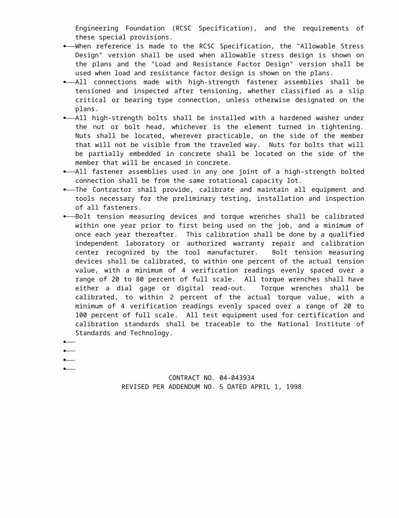
Addendum No. 11 04-CC,Sol-80-12.8/14.1,0.0/0.6Page 2 04-043934June 1, 1998
In the Special Provisions, Section 5-1.47 is added as follows:
"5-1.47 USE OF DREDGING MATERIALIf sand, gravel, aggregates, imported borrow or other minerals are dredged from San Francisco
Bay, the Contractor shall provide documentation that a permit from the Bay Conservation and Development Commission (BCDC) has been obtained. The documentation shall include the permit number, parcel number and specific location of the source of the material. The Contractor must also include this information on the HC-30 “Notice of Materials to be Used."
In the Special Provisions, Section 5-1.37, "Transportation For The Engineer" the following sentence of the first paragraph is deleted:
"The boat shall be made available within a maximum of 30 calendar days after award of the contract."
In the Special Provisions, Section 10-1.31E, "Dredging" is revised as follows:
10-1.31E DREDGINGAll excavation involved with the removal and disposal of the bay sediment material from within
the steel shells at cast-in-steel-shell concrete piling and permanent steel casings at cast-in-drilled-hole concrete piling and from inside the (temporary) cofferdam at Pier 5 of the "A4E" Line Mainspan structure shall be considered dredging under the terms of the various permits obtained by the State.
Dredged materials shall be disposed of at an upland (non-wetland) location. The Contractor shall provide construction access to accomplish the work without dredging.
Dredging will not be allowed to provide barge or equipment access to the various sites.Dredging shall be completed by using approved methods that will clean out and dispose of the
material in the steel shells, permanent steel-casings, and around the bases of the existing footings where required to complete the work in accordance with these special provisions. Unless otherwise authorized, all dredging shall be performed in the presence of the Engineer.
Dredging will be limited to the locations specified in these special provisions, and as shown on the plans.
Dredging shall be in accordance with the provisions of the various permits obtained by the Department. All dredged material shall be disposed of according to the permit requirements and these special provisions.
Attention is directed to "Order of Work" and "Non-Storm Water Discharges" elsewhere in these special provisions regarding time restrictions for certain items of work and footing excavation and pile dewater
Attention is directed to "Relations with California Department of Fish and Game," "Relations with California Regional Water Quality Control Board," "Relations with U.S. Coast Guard," "Relations with U.S. Army Corps of Engineers," and "Relations with Bay Conservation and Development Commission," elsewhere in these special provisions.
If excessive dredging occurs or dredged materials exceeds 4300 cubic yards, the Contractor shall report the locations of excessive dredging and quantities to the Engineer. The Contractor may be subject to sanctions by Federal, State and local agencies for excessive dredging.
Dredging Plan: Prior to beginning any dredging work, the Contractor shall submit a dredging plan as provided in Section 5-1.02, "Plans and Working Drawings," of the Standard Specifications for approval by the Engineer. Dredging shall not commence until all comments have been answered. The plan shall show order of dredging, barge anchoring locations, description of barge overflow operations, description of slurry operations, environmental pollution control measures, instrumentation used, coordinates and land elevations of all control points for electronic positioning system and Mean Sea Level (MSL) determination, estimated daily dredge advances, quality control procedures, anticipated problem areas of project involving poor access due to boat traffic congestion, boat docking, and procedures to assure that dredging will proceed within the contract limits. The quality control information shall include:

1) A description of the quality control organization, including a chart showing lines of authority and acknowledgment that the contractor quality control staff shall conduct the inspections for all aspects of the work specified and shall report to the Project Manager, or someone of higher authority, in the Contractor’s organization.

Addendum No. 11 04-CC,Sol-80-12.8/14.1,0.0/0.6Page 3 04-043934June 1, 1998
2) The name, qualifications, duties, responsibilities and authorities of each person assigned a quality control function.
3) A copy of the letter to the Contractor’s Quality Control (CQC) manager signed by an authorizing official of the firm, which describes the responsibilities and delegates the authorities of the CQC manager shall be furnished and shall be countersigned by the CQC manager acknowledging receipt of responsibilities and duties.
4) Reporting procedures and methods used to obtain information for quality control forms, including the submittal of displacement and capacity charts for all scows.
The dredging plan shall be updated on a weekly basis to allow notification to harbor and boat owners of dredge progress. The dredging plan shall include notices, schedules, plans, and controls needed to complete all the required dredging and disposal of material excavated from the Bay.
Overflow: No overflow of dredged material or water will be allowed from the receiving barges, dump scows, or any other transport receptacle during the dredging operations. Overflow will only be allowed if the Contractor includes provisions and operations acceptable to the Regional Water Quality Control Board and is approved in the Storm Water Pollution Prevention Plan prepared by the Contractor, as approved by the Engineer.
During transport to the disposal sites, water and dredged material shall not be permitted to overflow, spill, or leak out of barges or dump scows.
Monitoring of overflow time and leakage shall be as specified for quality control of dredging in these special provisions. The Contractor shall record draft of hull for each scow load as specified under quality control.
In the event the Contractor chooses to fill a receiving barge or dump scow, the receiving vessel shall be located in an approved anchor site in accordance with Section 5-1.22, "Relations With United States Coast Guard," of these special provisions. The Contractor shall be required to perform both a pre-dredge and a post-survey of the anchor site by means of an independent surveyor and the Contractor shall be required to remove any shoals attributed to his operation at no additional cost to the State. Surveys shall be in compliance with the requirements for “Hydrographic Surveys” elsewhere in these special provisions.
Control and Monitoring Surveys: A short to medium range Electronic Positioning System (EPS) or (GPS) Survey System shall be provided on all vessels involved in dredging operations. The EPS shall be established, operated and maintained by the Contractor during the period of the contract when dredging work is actively underway. The EPS using range-range methods shall display and record the vessel’s location continuously during dredging and transport for disposal.
The EPS system shall be similar or equal in design, performance, accuracy, operating characteristics, and frequency to those identified in the following technical reference, which is available for purchase at the listed source, or which may be reviewed at the Construction-Operations Division, San Francisco District Office, 333 Market Street, San Francisco, California.
“Hydrographic Surveying”Department of the ArmyEngineering Manual No. 1110-2-100328 February 1991USACE Publications Depot2803 52nd AvenueHyattsville, MD 20781-1102
The Contractor shall be responsible for establishing the horizontal control to locate active and/or passive shore-based EPS transmitter/receiver devices. All control shall meet Third Order, Class I, accuracy standards as defined (and referenced) under chapter 2 of the Army Corps of Engineers Manual “ Hydrographic Surveying”. The Contractor shall obtain all right-of-entry permits and/or leases as required to operate and maintain shore-based electronic equipment on public/private property at no additional cost to the State.

Addendum No. 11 04-CC,Sol-80-12.8/14.1,0.0/0.6Page 4 04-043934June 1, 1998
EPS calibration techniques shall conform to standard hydrographic surveying practice consistent with minimization of systematic errors inherent to and consistent with the selected EPS system as specified under Chapter 6 of the Army Corps of Engineers manual “Hydrographic Surveying”. The Contractor shall be responsible for accurate and reliable EPS calibration for the duration of this contract.
Transporting and Upland Disposal: The Contractor shall transport and dispose of the dredged material in accordance with these special provisions. Attention is directed to "Contaminated and Hazardous Material, General", and "Water Pollution Control,” of these special provisions and the conditions of the various permits obtained by the State for this contract.
During transport to the disposal sites, water and dredged material shall not be permitted to overflow, spill, or leak out of the barges or dump scows. The maximum tow speed shall be 6 knots for loaded barges.
A complete description of the Contractor’s plan for disposal, procedures used and schedules shall be defined in the dredging plan to the satisfaction of the Engineer.
Overflow and Leakage Monitoring Requirements--The Contractor shall furnish a diagram of the location of all overflow weirs for the barges and dump scows indicating the initial elevation of each weir relative to hopper bin curb height. Each change in elevation of a weir during the dredging work shall be indicated on the diagram. For barge overflow, where allowed, the Contractor shall furnish a diagram of the location and elevation of the overflow.
Barges or dump scows having more than 10% loss in draft while transporting material to the disposal site shall be recorded on the daily quality control report and shall not be used until repaired.
Measurement and Payment.--Materials excavated at Pier 5 of the "A4E" Line Mainspan structure shall be measured and paid for as structure excavation, (Type D) based on the limits shown on the plans.
Full compensation for preparing dredging plan, control and monitoring surveys, removing, dewatering, testing, transporting and disposing of the dredged material, and monitoring of overflow and leakage in accordance with the standard specifications and these special provisions shall be considered included in the contract price paid for the various items of work involving dredging and no additional compensation will be allowed therefor.
In the "Copy of Engineer's Estimate" in the NOTICE TO CONTRACTORS and the "Engineer's Estimate" in the PROPOSAL, Item 205 is revised as attached.
To Proposal and Contract book holders:
REPLACE PAGE 13 OF THE ENGINEER'S ESTIMATE IN THE PROPOSAL WITH THE ATTACHED REVISED PAGE 13 OF THE ENGINEER'S ESTIMATE. THE REVISED ENGINEER'S ESTIMATE IS TO BE USED IN THE BID SUBMITTAL AND INSERTED IN THE PROPOSAL.
INDICATE RECEIPT OF THIS ADDENDUM BY FILLING IN THE NUMBER OF THIS ADDENDUM IN THE SPACE PROVIDED ON THE SIGNATURE PAGE OF THE PROPOSAL.
Submit bids in the Proposal and Contract book you now possess. Holders who have already mailed their book will be contacted to arrange for the return of their book.
Inform subcontractors and suppliers as necessary.

Addendum No. 11 04-CC,Sol-80-12.8/14.1,0.0/0.6Page 5 04-043934June 1, 1998
This office is sending this addendum by UPS overnight mail to Proposal and Contract book holders to ensure that each receives it.
If you are not a Proposal and Contract book holder, but request a book to bid on this project, you must comply with the requirements of this letter before submitting your bid.
Sincerely,
NICK YAMBAO, ChiefPlans, Specifications &Estimates BranchOffice of Office Engineer
Attachments

The finish color of the nonskid surface shall be light gray.
Prior to applying epoxy and grit to galvanized surfaces, the surface to be coated shall be prepared in accordance with Section 59-3.02, "Surface Preparation," of the Standard Specifications.
The Contractor shall submit to the Engineer for approval a method of application stating the spread rate of epoxy and grit and the number of coats. The Contractor shall demonstrate the method of application to the Engineer, prior to placing any nonskid material, by preparing a one square foot sample placed on 1/4 inch hardboard. The nonskid surface shall have a total thickness of between 1/8 inch and 3/16 inch.
At the option of the Contractor, a commercial quality nonskid surface, comprised of a two component ultra violet resistant epoxy and grit of quality equal to the above requirements, may be submitted to the Engineer for approval.
MEASUREMENT AND PAYMENT.--Full compensation for furnishing and placing nonskid surface shall be considered as included in the contract lump sum price paid for temporary deck bridging and no separate payment will be made therefor.
The contract lump sum price paid for temporary deck bridging shall include full compensation for furnishing all labor, materials, tools, equipment, and incidentals for doing all the work involved in designing, furnishing, installing, maintaining, removing and replacing as necessary to maintain traffic and finally removing the temporary deck bridging, as specified in the Standard Specifications and these special provisions, and as directed by the Engineer.
10-1.09 COOPERATIONAttention is directed to Sections 7-1.14,
"Cooperation," and 8-1.10, "Utility and Non-Highway Facilities," of the Standard Specifications, "Obstructions" elsewhere in these special provisions and these special provisions.
The Contractor shall be responsible for coordinating with the persons for the various agencies involved on this project as they affect the progress of the work. Key contacts are as follows:
Union Pacific Rail Road (formerly Southern Pacific)Contact: Manager of Public Projects,
Engineering Dept.Phone: (415) 541-1421
Pacific Gas and Electric CompanyContact: Land AgentPhone: (510) 674-6433
Pacific Bell TelephoneContact: Public Works CoordinatorPhone: (510) 823-6791
Crockett COGENContact: ManagerPhone: (510) 787-4102
East Bay Municipal Utilities DistrictContact: North Area SupervisorPhone: (510) 287-0831
TCIContact: Construction SupervisorPhone: (510) 432-0500
Crockett Valona Sewer DistrictContact: ManagerPhone: (510) 787-2992
It is anticipated that work will be in progress by other contractors within or adjacent to the limits of this contract.
Contracts which may be in progress during the working period of this contract include but are not necessarily limited to the following:
Contract No. 044974 FasTRAK ProjectContract No. 150954 Traffic Operations System
(TOS) Project.Contract No. 044024 Benicia-Martinez Bridge
Retrofit. This is a seismic retrofit project.Contract No. 0440U4 Benicia-Martinez Bridge
Retrofit. This is a seismic retrofit project.Carquinez Replacement Projects.
Any work within the Contra Costa County right-of-way will require an encroachment permit. All road closures within Contra Costa County will require a road closure permit. The Contractor shall obtain the necessary permits by contacting Contra Costa County at (510) 646-1607.
Work by State maintenance forces will also be in progress within the contract limits during the working period for this contract.
Progress schedules for other work in progress, if available, may be inspected by the Contractor. Such progress schedules are tentative and cannot be guaranteed accurate.
The Contractor shall cooperate with C&H Sugar Company for any work within the C&H property in order for C&H to maintain their operations. Coordination with C&H shall be through the Engineer.
The Contractor shall participate in weekly work planning meetings with the Engineer for the purpose of coordinating his work with the work of other contractors, State, and other agency forces.
10-1.10 PROGRESS SCHEDULE (CRITICAL PATH)
Progress schedules will be required for this contract. Progress schedules shall utilize the Critical Path Method (CPM).
Definitions - The following definitions apply to this section "Progress Schedule (Critical Path)":
1) Activity: Any task, or portion of a project which takes time to complete.
2) Baseline Schedule: The initial CPM schedule representing the Contractor's
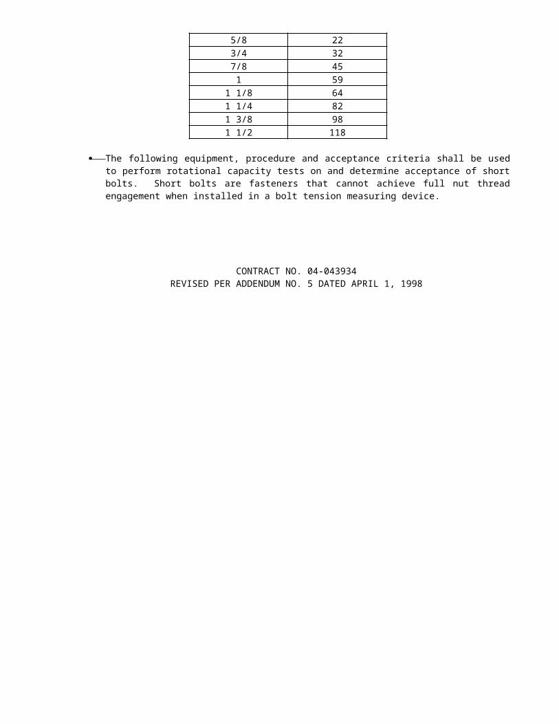
original work plan, as accepted by the Engineer.
3) Critical Path Method: A mathematical calculation to determine the longest path of work and relative float represented by a graphic representation of the sequence of activities that shows the interrelationships and interdependencies of the elements composing a project.
4) Current Contract Completion Date: The extended date for completion of the contract shown on the weekly statement of working days furnished by the Engineer in accordance with Section 8-1.06, "Time of Completion," of the Standard Specifications.
5) Early Completion Time: The difference in time between the current contract completion date and the Contractor's scheduled early completion date as shown on the accepted baseline schedule, or schedule updates and revisions.
6) Float: The amount of time between the early start date and the late start date, or the early finish date and the late finish date, of any activity or group of activities in the network.
7) Fragnet: A section or fragment of the network diagram comprised of a group of activities.
8) Hammock Activity: An activity added to the network to span an existing group of activities for summarizing purposes.
9) Milestone: A marker in a network which is typically used to mark a point in time or denote the beginning or end of a sequence of activities. A milestone has zero duration, but will otherwise function in the network as if it were an activity.
10) Revision: A change in the future portion of the schedule that modifies logic, adds or deletes activities, or alters activities, sequences, or durations.
11) Tabular Listing: A report showing schedule activities, their relationships, durations, scheduled and actual dates, and float.
12) Total Float: The amount of time that an activity may be delayed without affecting the total project duration of the critical path.
13) Update: The modification of the CPM progress schedule through a regular review to incorporate actual progress to date by activity, approved time adjustments, and projected completion dates.
Preconstruction Scheduling Conference - The Engineer will schedule and conduct a Preconstruction Scheduling Conference with the Contractor's Project Manager and Construction Scheduler within seven days after the bidder has received the contract for execution. At this meeting, the requirements of this section of the
special provisions will be reviewed with the Contractor. The Contractor shall be prepared to discuss its schedule methodology, proposed sequence of operations, and any deviations it proposes to make from the Stage Construction Plans. At this meeting, the Contractor shall submit its proposed work breakdown structure, the associated alpha-numeric coding structure to implement the work breakdown structure and the activity identification system for labeling all work activities. The Engineer shall review and comment on the work breakdown structure, the coding structure and activity identification system within seven days after submission by the Contractor. The Contractor shall make all modifications to the proposed work breakdown structure, the coding structure and activity identification system that are requested by the Engineer, and shall employ that coding, structure and system in its baseline schedule submission.
Interim Baseline Schedule - Within 10 days after approval of the contract, the Contractor shall submit to the Engineer an interim baseline project schedule which will serve as the progress schedule for the first 120 days of the project, or until the baseline schedule is accepted, whichever is sooner. The interim baseline schedule shall utilize the critical path method. The interim baseline schedule shall depict how the Contractor plans to perform the work for the first 120 days of the contract. Additionally, the interim baseline schedule shall show all submittals required early in the project, and shall provide for all permits, and other non-work activities necessary to begin the work. The interim baseline schedule submittal shall include a diskette which contains the data files used to generate the schedule.
The Engineer shall be allowed 15 calendar days to review and accept or reject the interim baseline schedule submitted. Rejected schedules shall be resubmitted to the Engineer within 5 calendar days of receipt by the Contractor of the Engineer's comments, at which time a new 15-calendar day review period by the Engineer will begin.
Baseline Schedule - Within 30 days after approval of the contract, the Contractor shall submit to the Engineer a baseline project schedule. The baseline schedule shall include the activities shown on the interim baseline schedule in the same order and logical relationship as shown in the interim baseline schedule. The baseline project schedule shall have a data date of the day prior to the first working day of the contract and shall not include any completed work to-date. The baseline progress schedule shall meet interim target dates, milestones, stage construction requirements, internal time constraints, show logical sequence of activities, and must not extend beyond the number of days originally provided for in the contract.
The baseline CPM schedule submitted by the Contractor shall have a sufficient number of activities to assure adequate planning of the project and to permit monitoring and evaluation of progress and the analysis of
CONTRACT NO. 04-043934REISSUED PER ADDENDUM N0. 11 DATED JUNE 1, 1998
64
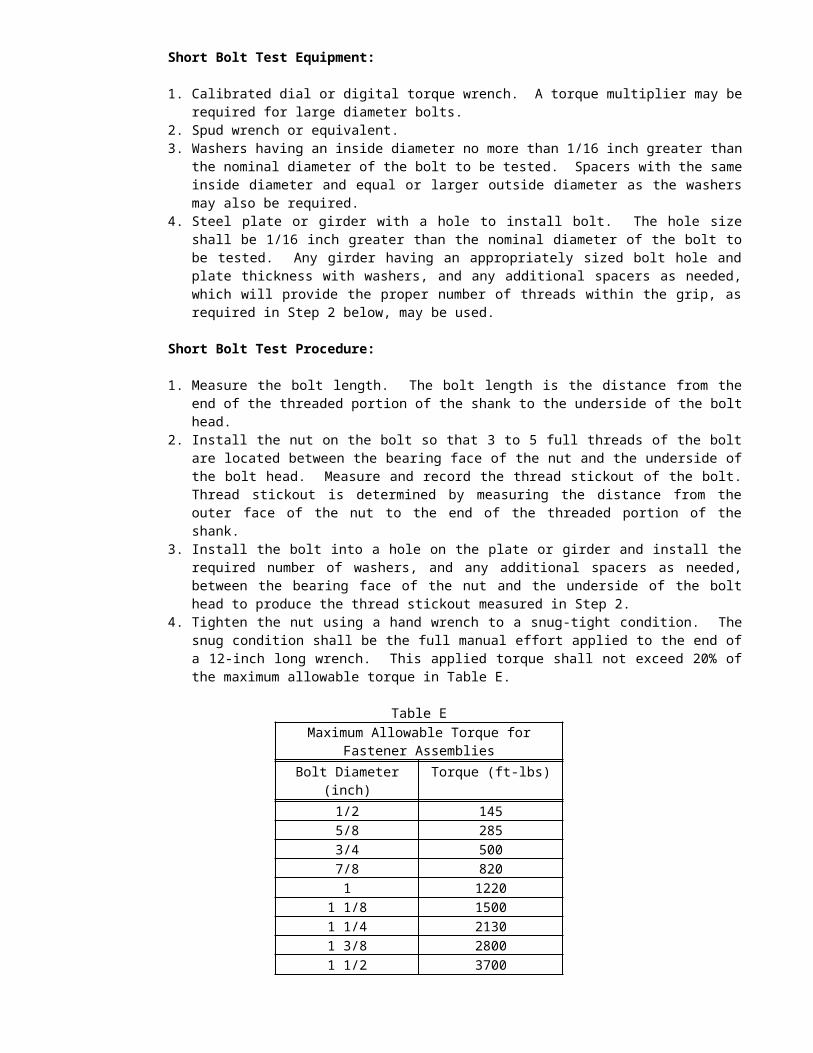
time impacts. The baseline schedule shall depict how the Contractor plans to complete the whole work involved, and shall show all activities that define the critical path.
The baseline progress schedule shall be supplemented with resource allocations for every activity, to a level of detail that facilitates report generation based on labor craft and equipment class for the Contractor and subcontractors. The Contractor shall use average composite crews to display the labor loading of on-site construction activities. The Contractor shall optimize and level labor to reflect a reasonable plan for accomplishing the work of the contract and to assure that resources are not duplicated in concurrent activities. The Contractor shall require each subcontractor to submit in writing a statement certifying that the subcontractor has concurred with the Contractor's CPM, including major updates, and that the subcontractor's related schedule has been incorporated accurately, including the duration of activities and labor and equipment loading. Along with the baseline progress schedule, the Contractor shall also submit to the Engineer time-scaled resource histograms of the labor crafts and equipment classes to be utilized on the contract.
The Engineer shall be allowed 15 calendar days to review and accept or reject the baseline project schedule submitted. Rejected schedules shall be resubmitted to the Engineer within 5 calendar days, at which time a new 15-calendar day review period by the Engineer will begin.
Project Schedule Reports - Schedules submitted to the Engineer including baseline and interim baseline schedules shall include time scaled network diagrams. Network diagrams shall be based on early start and early finish dates of activities shown. The network diagrams submitted to the Engineer shall also be accompanied by the computer-generated mathematical analysis tabular reports for each activity included in the project schedule. Three different report sorts shall be provided: Early Start, Total Float, and Activity Number, which shall show all predecessors and successors for each activity. The mathematical analysis tabular reports (8 1/2" x 11" size) shall be submitted to the Engineer and shall include, at a minimum, the following:
1) Data date2) Predecessor and successor activity numbers
and descriptions;3) Activity number and description;4) Activity codes;5) Schedule, and actual and remaining
duration for each activity;6) Earliest start date (by calendar date);7) Earliest finish date (by calendar date);8) Actual start date (by calendar date);9) Actual finish date (by calendar date);10) Latest start date (by calendar date);11) Latest finish date (by calendar date);12) Identify actual non-working days13) Identify activity calendar type14) Float, in work days;
15) Percentage of activity complete and remaining duration for incomplete activities; and
16) Imposed constraints.
Networks shall be drafted time scaled to show a continuous flow of information from left to right. The primary paths of criticality shall be clearly and graphically identified on the networks. The network diagram shall be prepared on E-size sheets (36" x 48"), shall have a title block in the lower right-hand corner, and a timeline on each page. Exceptions to the size of the network sheets and the use of computer graphics to generate the networks shall be subject to the approval of the Engineer.
Schedule network diagrams and computer tabulations shall be submitted to the Engineer for acceptance in the following quantities:
a) 2 sets of the Network Diagrams;b) 2 copies of the computer tabulation reports
(8 1/2" x 11" size); andc) 3 computer diskettes.
Should the baseline schedule or schedule update, submitted for acceptance, show variances from the requirements of the contract, the Contractor shall make specific mention of the variations in the letter of transmittal, in order that, if accepted, proper adjustments to the project schedule can be made. The Contractor will not be relieved of the responsibility for executing the work in strict accordance with the requirements of the contract documents. In the event of a conflict between the requirements of the contract documents and the information provided or shown on an accepted schedule, the requirements of the contract documents shall take precedence.
Each schedule submitted to the Engineer shall comply with all limits imposed by the contract, with all specified intermediate milestone and completion dates, and with all constraints, restraints or sequences included in the contract. The degree of detail shall include factors including, but not limited to:
1) Physical breakdown of the project;2) Contract milestones and completion dates,
substantial completion dates, constraints, restraints, sequences of work shown in the contract, the planned substantial completion date, and the final completion date;
3) Type of work to be performed, the sequences, and the major subcontractors involved;
4) All purchase, submittals, submittal reviews, manufacture, tests, deliver, and installation activities for all major materials and equipment.
5) Preparation, submittal and approval of shop and working drawings and material samples, showing time, as specified elsewhere, for the Engineer's review. The same time frame shall be allowed for at
CONTRACT NO. 04-043934REISSUED PER ADDENDUM N0. 11 DATED JUNE 1, 1998
65

least one resubmittal on all major submittals so identified in the contract documents;
6) Identification of interfaces and dependencies with preceding, concurrent and follow-on contractors, railroads, and utilities as shown on the plans or specified in the specifications;
7) Identification of each and every utility relocation and interface as a separate activity, including activity description and responsibility coding that identifies the type of utility and the name of the utility company involved.
8) Actual tests, submission of test reports, and approval of test results;
9) All start-up, testing, training, and assistance required under the Contract;
10) Punchlist and final clean-up;11) Identification of any manpower, material,
or equipment restrictions, as well as any activity requiring unusual shift work, such as double shifts, 6-day weeks, specified overtime, or work at times other than regular days or hours; and
12) Identification of each and every ramp closing and opening event as a separate one-day activity, including designation by activity coding and description that it is a north-bound, south-bound, east-bound, west-bound, and entry or exit ramp activity.
Each construction activity shall have a duration of not more than 20 working days, and not less than one working day unless permitted otherwise by the Engineer. All activities in the schedule, with the exception of the first and last activities, shall have a minimum of one predecessor and a minimum of one successor. The baseline schedule shall not attribute negative float to any activity. Float shall not be considered as time for the exclusive use of or benefit of either the State or the Contractor but shall be considered as a jointly owned, expiring resource available to the project and shall not be used to the financial detriment of either party. Any accepted schedule, revision or update having an early completion date shall show the time between the early completion date and the current Contract Completion Date as "project float".
The Contractor shall be responsible for assuring that all work sequences are logical and the network shows a coordinated plan for complete performance of the work. Failure of the Contractor to include any element of work required for the performance of the contract in the network shall not relieve the Contractor from completing all work within the time limit specified for completion of the contract. If the Contractor fails to define any element of work, activity or logic, and the omission or error is discovered by either the Contractor or the Engineer, it shall be corrected by the Contractor at the next monthly update or revision of the schedule.
Monthly Update Schedules - The Contractor shall submit a Monthly Update Schedule to the Engineer once in each month. The proposed update schedule prepared by the Contractor shall include all information available as of the 20th calendar day of the month, or other date as established by the Engineer. A detailed list of all proposed schedule changes such as logic, duration, lead/lag, additions and deletions shall be submitted with the update.
The monthly update schedule submitted to the Engineer shall be accompanied by a Schedule Narrative Report. The Schedule Narrative Report shall describe the physical progress during the report period, plans for continuing the work during the forthcoming report period, actions planned to correct any negative float predictions, and an explanation of potential delays or problems and their estimated impact on performance, milestone completion dates and the overall project completion date. In addition, alternatives for possible schedule recovery to mitigate any potential delay or cost increases shall be included for consideration by the Engineer. The report shall follow the outline set forth below:
Contractor's Schedule Narrative Report Outline:
1) Contractor's Transmittal Letter2) Work completed during the period3) Description of the current critical path4) Description of problem areas5) Current and anticipated delays
a) Cause of the delayb) Corrective action and schedule
adjustments to correct the delayc) Impact of the delay on other activities,
milestones, and completion dates6) Changes in construction sequences7) Pending items and status thereof
a) Permitsb) Change Ordersc) Time Extensionsd) Non-Compliance Notices
8) Contract completion date(s) statusa) Ahead of schedule and number of daysb) Behind schedule and number of days
9) Include updated Network Diagram and Reports
The Contractor shall provide to the Engineer a 31/2” electronic disk of the schedule, together with printed copies of the network diagrams and tabular reports described under "Project Schedule Reports", and the Schedule Narrative Report.
The monthly update of the schedule shall be for the period from the last update to the current cut-off date, and for the remainder of the project. The current period's activities shall be reported as they actually took place and designated as actually complete, if actually completed, in the schedule updates.
CONTRACT NO. 04-043934REISSUED PER ADDENDUM N0. 11 DATED JUNE 1, 1998
66

Portions of the network diagram on which all activities are complete need not be reprinted and submitted
CONTRACT NO. 04-043934REISSUED PER ADDENDUM N0. 11 DATED JUNE 1, 1998
67

in subsequent updates. However, the electronic disk file of the submitted schedule and the related reports shall constitute a clear record of progress of the work from award of contract to final completion.
The Contractor will be permitted to show early or late completion on schedule updates and revisions. The Engineer may use the updates and revisions, and other information available, in evaluating the effect of changes, delays, or time savings on the critical path and the accepted schedule current at the time to determine if there is an applicable adjustment of time, if any, to any target date or completion date due to the changes, delays, or time savings.
On a date determined by the Engineer, the Contractor shall meet with the Engineer to review the monthly schedule update. At the monthly progress meeting, the Contractor and the Engineer will review the updated schedule and will discuss the content of the Narrative Report. The Engineer shall be allowed 15 days after the meeting to review and accept or reject the update schedule submitted. Rejected schedules shall be resubmitted to the Engineer within 15 calendar days, at which time a new 15-calendar day review period by the Engineer will begin.
Schedule Revisions - If the Contractor desires to make a change to the accepted schedule, the Contractor shall request permission from the Engineer in writing, stating the reasons for the change, and proposed revisions to activities, logic and duration. The Contractor shall submit for acceptance the affected portions of the project schedule and an analysis to show the effect on the entire project. The Engineer will provide a response within 10 days. No revision to the accepted baseline schedule or the schedule updates shall be made without the prior written approval of the Engineer.
The Engineer will request the Contractor to submit a proposed revised schedule within 15 days when:
a) there is a significant change in the Contractor's operations that will affect the critical path;
b) the current updated schedule indicates that the contract progress is 30 calendar days or more behind the planned schedule, as determined by the Engineer; or
c) the Engineer determines that an approved or anticipated change will impact the critical path, milestone or completion dates, contract progress, or work by other contractors.
The Engineer shall be allowed 15 days to review and accept or reject a schedule revision. Rejected schedule revisions shall be revised and resubmitted to the Engineer within 15 calendar days, at which time a new 15-calendar day review period by the Engineer will begin. Only upon approval of a change by the Engineer shall it be reflected in the next schedule update submitted by the Contractor.
Schedule Time Extension Requests - When the Contractor requests a time extension due to contract change orders or delays, the Contractor shall submit to the Engineer a written Time Impact Analysis illustrating the influence of each change or delay on the current contract completion date or milestone completion date, utilizing the current accepted schedule. Each Time Impact Analysis shall include a fragnet demonstrating how the Contractor proposes to incorporate the Change Order or delay into the current schedule. The fragnet shall include the sequence of new and existing activity revisions that are proposed to be added to the accepted baseline project schedule or current schedule in effect at the time the change or delay is encountered, to demonstrate the influence of the delay and the proposed method for incorporating the delay and its impact into the schedule.
Each Time Impact Analysis shall demonstrate the estimated time impact based on the events of delay, the anticipated or actual date of the contract change order work performance, the status of construction at that point in time, and the event time computation of all activities affected by the change or delay. The event times used in the analysis shall be those included in the latest update of the current schedule in effect at the time the change or delay was encountered.
Time extensions will be granted only to the extent that equitable time adjustments for the activity or activities affected exceed the total or remaining float along the critical path of activities at the time of actual delay, or at the time the contract change order work is performed. Float time is not for the exclusive use or benefit of the Engineer or the Contractor, but is an expiring resource available to all parties as needed to meet contract milestones and the contract completion date. Time extensions will not be granted nor will delay damages be paid unless:
a) the delay is beyond the control and without the fault or negligence of the Contractor and its subcontractors or suppliers, at any tier; and,
b) the delay extends the actual performance of the work beyond the applicable current contract completion date and the most recent date predicted for completion of the project on the accepted schedule update current as of the time of the delay or as of the time of issuance of the contract change order.
Time Impact Analyses shall be submitted in triplicate within 15 days after the delay occurs or after issuance of the contract change order.
Approval or rejection of each Time Impact Analysis by the Engineer will be made within 15 days after receipt of the Time Impact Analysis, unless the review is delayed by subsequent meetings and negotiations. A copy of the Time Impact Analysis approved by the Engineer shall be returned to the Contractor and the accepted schedule revisions illustrating the influence of the contract change orders or delays shall be
CONTRACT NO. 04-043934REISSUED PER ADDENDUM N0. 11 DATED JUNE 1, 1998
68

incorporated into the project schedule during the first update after approval.
Final Schedule Update - Within 15 days after the acceptance of the contract by the Director, the Contractor shall submit a final update of the schedule with actual start and actual finish dates for all activities. This schedule submission shall be accompanied by a certification, signed by an officer of the company and the Contractor's Project Manager stating "To the best of my knowledge, the enclosed final update of the project schedule reflects the actual start and completion dates of the activities contained herein."
Equipment and Software - The Contractor shall provide for the State's exclusive possession and use a complete computer system specifically capable of creating, storing, updating and producing CPM schedules. Before delivery and setup of the computer system, the Contractor shall submit to the Engineer for approval a detailed list of all computer hardware and software the Contractor proposes to furnish. The minimum computer system to be furnished shall include the following:
1) Complete computer system, including keyboard, mouse, 17 inch color SVGA monitor (1,024x768 pixels), Intel Pentium 200 MHZ micro processor chip, or equivalent, or better.
2) Computer operating system software, compatible with the selected processing unit, for Windows 95 or later, or equivalent.
3) Minimum sixty-four (64) megabytes of random access memory (RAM).
4) A two-gigabyte minimum hard disk drive, a 1.44 megabyte 3 l/2 inch floppy disk drive, 16x speed minimum CD-ROM drive, and ethernet card.
5) A color-ink-jet plotter with a minimum 8 megs RAM, capable of 300 dots per inch color, 600 dots per inch monochrome, or equivalent plotter capable of printing fully legible, timescaled charts, and network diagrams, in four colors, with a minimum size of 36 inches by 48 inches (E size) and is compatible with the selected system.
6) CPM software shall be Primavera Project Planner, version 2.0 for Windows 95, or later.
The computer hardware and software furnished shall be compatible with that used by the Contractor for the production of the CPM progress schedule required by the Contract, and shall include original instruction manuals and other documentation normally provided with the software.
The Contractor shall furnish, install, set up, maintain and repair the computer hardware and software ready for use at a location determined by the Engineer. The hardware and software shall be installed and ready for use by the first submission of the baseline schedule. The Contractor shall provide 24 hours of formal training for the Engineer in the use of the hardware and software to include schedule analysis, reporting, resource and cost allocations.
All computer hardware and software furnished shall remain the property of the Contractor and shall be removed by the Contractor upon acceptance of the contract when no claims involving contract progress are pending. When claims involving contract progress are pending, computer hardware or software shall not be removed until the final estimate has been submitted to the Contractor.
Payment - Progress schedule (critical path) will be paid for at a lump sum price. The contract lump sum price paid for progress schedule (critical path) shall include full compensation for furnishing all labor, materials (including computer hardware and software), tools, equipment, and incidentals; and for doing all the work involved in preparing, furnishing, updating and revising CPM progress schedules; maintaining and repairing the computer hardware; and training the Engineer in the use of the computer hardware and software; as specified in the Standard Specifications and these special provisions, and as directed by the Engineer.
Payments for progress schedule (critical path) will be made as follows:
Interim baseline schedule accepted, then 10 percent payment for progress schedule (critical path) will be made.
Baseline schedule accepted, then 10 percent payment for progress schedule (critical path) will be made.
Monthly update schedules accepted, then 75 percent payment for progress schedule (critical path) will be made equally for each update.
Final schedule update accepted, then 5 percent payment for progress schedule (critical path) will be made.
The Department will retain an amount equal to 25 percent of the estimated value of the work performed during the first estimate period in which the Contractor fails to submit an interim baseline, baseline, revised or updated CPM schedule conforming to the requirements of this section, as determined by the Engineer. Thereafter, on subsequent successive estimate periods the percentage the Department will retain will be increased at the rate of 25 percent per estimate period in
CONTRACT NO. 04-043934REISSUED PER ADDENDUM N0. 11 DATED JUNE 1, 1998
69

which acceptable CPM progress schedules have not been submitted to the Engineer. Retentions for failure to submit acceptable CPM progress schedules shall be additional to all other retentions provided for in the contract. The retention for failure to submit acceptable CPM progress schedules will be released for payment on the next monthly estimate for partial payment following the date that acceptable CPM progress schedules are submitted to the Engineer.
The adjustment provisions in Section 4-1.03, "Changes," of the Standard Specifications, shall not apply to the item of progress schedule (critical path).
CONTRACT NO. 04-043934REISSUED PER ADDENDUM N0. 11 DATED JUNE 1, 1998
70
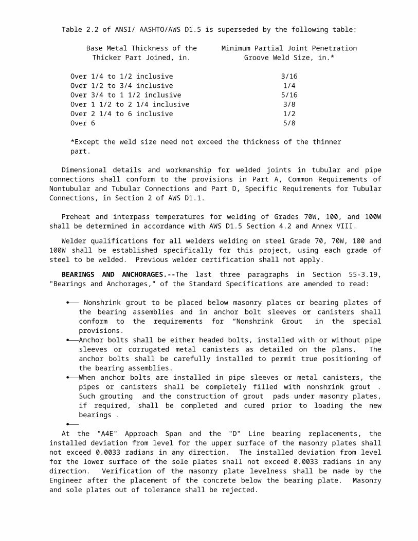
Adjustments in compensation for the project schedule will not be made for any increased or decreased work ordered by the Engineer in furnishing project schedules.
10-1.11 ELECTRONIC MOBILE DAILY DIARY COMPUTER SYSTEM
The Contractor shall provide for the State’s exclusive possession and use a complete electronic mobile daily diary computer system, to allow State personnel to record observation (diary) data in the field using Personal Digital Assistants (PDAs), and in the office using desktop workstation(s). Recorded data will be uploaded to a database maintained on an Oracle server. Diary information in the database shall be capable of being edited and printed in the form of an Engineer’s Daily Report from desktop workstations connected to the database via a local area network. The system will also provide other reports required by the Engineer, as well as user friendly and rapid retrieval of daily reports and other information from the database for research purposes.
The Engineer may use the furnished computer hardware, software, and instruction manual for any purposes related to the subject project. Before delivery and set up of the computer system the Contractor shall submit to the Engineer for approval a detailed list of all computer hardware and software the Contractor proposes to furnish. All computer hardware and software furnished shall remain the property of the Contractor and shall be removed by the Contractor upon acceptance of the contract when no claims are pending and after the final estimate has been submitted to the Contractor.
The electronic mobile daily diary computer system furnished shall meet the requirements described below for function, data, hardware, and support.
FUNCTIONAL REQUIREMENTS.--The Contractor shall provide not later than 5 days after the beginning of the contract completion time a computer system that complies with the following minimum functional specifications:
Data Collection Subsystem 1. Accept input of observation
data.
General dataAllow input of data that applies to all
observation data sets: Inspector ID: agency-specific code;
allow up to 10 alphanumeric characters. Inspector password: general text field;
allow up to 10 characters. Inspector name: general text field; allow
up to 30 characters. Inspector title: general text field; allow
up to 30 characters.
Daily contract observation data
Collect one or more contract observation data sets per contract per inspector per day:
Observation date: month, day & year. Contract ID: agency-specific code;
allow up to 15 alphanumeric characters. Uniqueness guarantor: time and time of
creation of the data set. Weather condition, am and pm: agency-
specific code of up to 10 alphanumeric characters.
Temperature, high and low: signed numeric value of up to 3 digits (degrees Fahrenheit or Celsius).
Humidity, high and low: percentage value (0 to 100%).
Start and stop time for inspector shift (24-hour clock; values at the half hour).
Start and stop time for jobsite shift (24-hour clock; values at the half hour).
Level of inspection: values are “continuous”, “intermittent” and “no inspection”.
Inspector signature: digital image of signature.
Laborer observation dataCollect multiple labor observations per
observation data set: Contract item or Contract Change Order
(CCO): sequential number; allow up to 6 digits.
Contractor ID: agency-specific code; allow up to 10 alphanumeric characters.
Critical Path Method next work (CPM) activity code: agency-specific code; allow up to 10 alphanumeric characters.
Structure/Line: agency-specific code; allow up to 10 alphanumeric characters.
Location/Station: general text field; allow up to 60 characters.
Laborer name: last, first, & middle initial.
Labor classification: agency-specific code; allow up to 10 alphanumeric characters.
Trainee status: Boolean value. Hours: numeric value (0 to 24; up to 2
places behind the decimal point). Hours type flag: flag value to indicate
regular vs. overtime hours. Force account flag: Boolean value (CCO
observations only).
Equipment observation dataCollect multiple equipment observations
per observation data set: Contract item or CCO: sequential
number; allow up to 6 digits. Contractor ID: agency-specific code;
allow up to 10 alphanumeric characters.
CONTRACT NO. 04-043934REISSUED PER ADDENDUM N0. 11 DATED JUNE 1, 1998
71

CPM activity code: agency-specific code; allow up to 10 alphanumeric characters.
Stucture/Line: agency-specific code; allow up to 10 alphanumeric characters.
Location/Station: general text field; allow up to 60 characters.
Equipment ID: contractor-specific code; allow up to 10 alphanumeric characters.
Equipment description (“new” equipment only): general text field; allow up to 60 characters.
Rental status: Boolean value. Hours: numeric value (0 to 24; up to 2
places behind the decimal point). Hours type flag: flag value to indicate
regular vs. overtime vs. idle hours. Force account flag: Boolean value (CCO
observations only).
Pay Items observation dataCollect multiple pay items observations per
observation data set: Contract item or CCO: sequential
number; allow up to 6 digits. Contractor ID: agency-specific code;
allow up to 10 alphanumeric characters. CPM activity code: agency-specific
code; allow up to 10 alphanumeric characters.
Stucture/Line: agency-specific code; allow up to 10 alphanumeric characters.
Location/Station: general text field; allow up to 60 characters.
Load ticket ID: Contractor-specific value; allow up to 15 alphanumeric characters.
Quantity: numeric value; floating point (11,2) specification.
Lot number: Contractor-specific value; allow up to 15 alphanumeric characters.
Lab release number: contractor-specific value; allow up to 15 alphanumeric characters.
Force account flag: Boolean value (CCO observations only).
Units type (force account observations only): agency-specific code; allow up to 10 alphanumeric characters.
Material type (force account observations only): general text field; allow up to 60 characters.
Remarks dataCollect multiple remarks per observation
data set: Contract item or CCO (optional):
sequential number; allow up to 6 digits. Contractor ID (optional): agency-
specific code; allow up to 10 alphanumeric characters.
CPM activity code: agency-specific code; allow up to 10 alphanumeric characters.
Stucture/Line: agency-specific code; allow up to 10 alphanumeric characters.
Location/Station: general text field; allow up to 60 alphanumeric characters.
Remark type: agency-specific code; allow up to 10 alphanumeric characters.
Remark text: general text field; allow up to 2,000 characters.
Force account flag: Boolean value (CCO observations only).
2. Provide meaningful display of coded information.
Display contract descriptions in addition to contract numbers.
Display item/CCO descriptions in addition to item/CCO numbers.
Display CPM activity descriptions in addition to CPM activity codes.
Display Contractor names in addition to Contractor IDs.
Display equipment descriptions in addition to equipment IDs.
Display labor classification descriptions in addition to labor classification codes.
Display material types and units of measure based on contract item number.
Display weather condition descriptions in addition to weather condition codes.
3. Facilitate entry of inspection data.
In general, methods of data entry shall require the minimum number of actions or keystrokes from the user as is practical
Provide pick lists from the central database for entry of the following fields,: Contract numbers. Contract item numbers. Contractor IDs. Laborers. Labor classifications. Equipment. Remark types. Weather conditions (am and pm).
Also provide alphabetical tabs for navigating the list of laborer.
Provide option of handwriting or typewriter keypad entry for the following fields: Inspector ID, password, name, and
title. CPM activity code. Load ticket number. Lot number. Lab release number. Materials location.
CONTRACT NO. 04-043934REISSUED PER ADDENDUM N0. 11 DATED JUNE 1, 1998
72

Remark text. Laborer name for “new” people. Equipment ID and description for
“new” equipment.
CONTRACT NO. 04-043934REISSUED PER ADDENDUM N0. 11 DATED JUNE 1, 1998
73

Provide option of handwriting or numeric keypad entry for the following fields: Contract item number. Materials quantity. Temperatures (high and low). Humidity (high and low).
Provide “clock” controls for entry of the following fields: Inspector shift hours. Jobsite shift hours. Hours (labor & equipment
observations). Provide calendar keypad entry for the
following fields: Observation date.
Provide checkboxes for entry of the following Boolean fields: Trainee status. Rental status. Force account status.
Provide radio buttons for entry of the following fields: Hours type flag (regular, overtime,
idle). Provide popup menu for entry of the
following fields: Level of inspection.
Copy into labor & equipment observations relevant ratebook codes and values from the central database.
Provide option to use handwriting or typewriter keypad to enter equipment ID for equipment observations and look up the corresponding piece of equipment, as an alternative to choosing the piece of equipment from a list.
Provide option to change the labor classification for a labor observation even if the laborer name and classification have been selected from a list (to allow observations of laborers working out of their normal classes).
4. Store observation data sets. Store all entered data on the mobile
platform for up to 100 observations (any combination of types) per contract observation data set.
Store data for up to 30 observation data sets on the mobile platform.
Store or backup data on non-volatile memory to guard against data loss.
5. Support review and modification of observation data sets.
Allow user to select observation data sets from a list by identifying: Engineer ID. Observation date. Contract number.
Once a data set is selected, display all observation entries in an overview list. Allow list to be sorted by observation type, contract item, or Contractor. Also allow list to be restricted by observation type (labor, equipment, materials, or remarks) so that additional data can be displayed for the observations (e.g., labor name, hours & hours type for labor entries).
Provide option to duplicate observation entries from the list, optionally setting item number & hours fields to new values.
Allow list entries to be selected and edited.
Allow user to update weather condition and shift hour data.
Allow user to duplicate entire observation data sets to a new date selected by the user.
Allow user to delete observation data sets (after confirmation).
6. Communicate with database server to upload diaries and download control tables.
Allow user to mark diaries as “done” and collect a signature image at that time. After the diary has been signed, prohibit any other modifications to the diary. If diary is marked “undone” then allow modifications but throw away signature, so that a new signature is always required at whatever point the diary is marked “done” (i.e., ready for transmission).
Connect to communications server via direct serial connection, providing database user ID and password.
Send observation data. Select for transmission all
observation data sets marked “done” that have not yet been transmitted.
Output a serial stream containing the observation data sets to be transmitted.
Display status during transmission and provide confirmation that data was sent to the server.
Set a flag in transmitted data sets to indicate that they have been transmitted.
Be capable of handling unexpected interruptions in the communication link.
Receive control table data. Automatically request all necessary
control table downloads, providing both user ID and date of last download.
CONTRACT NO. 04-043934REISSUED PER ADDENDUM N0. 11 DATED JUNE 1, 1998
74
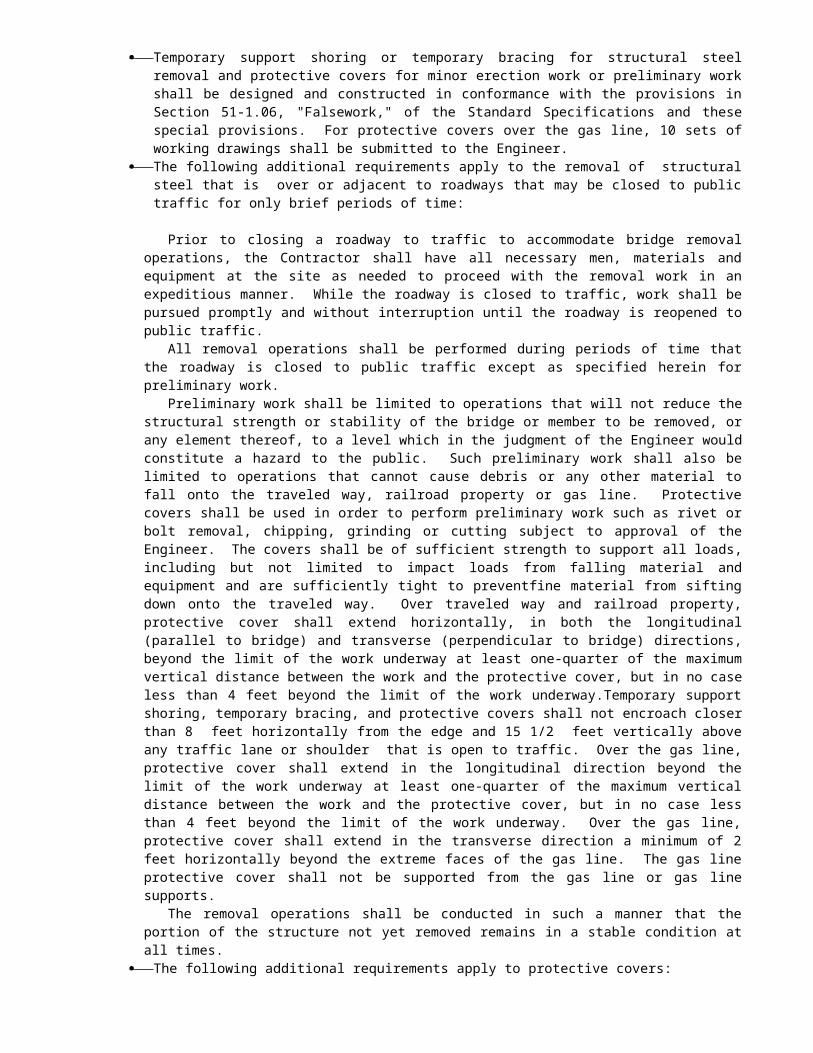
Accept a serial stream containing control table updates.
Display status during transmission and provide confirmation that data was received from the server.
Set the date of last update for received control tables.
Be capable of handling unexpected interruptions in the communication link.
7. Provide additional productivity support.
Display a list of names with addresses, phone numbers, radio call numbers and vehicle IDs. List entries must be transparently downloaded from a central database along with other control table data.
Provide a programmable scientific calculator option.
8. Provide adequate hardware functionality for hand-held computer.
Allow data (other than signature image) to be entered with choice of either pen or keyboard.
Weigh less than 2 pounds. Battery to have a life of at least 4
continuous hours between chargings. Provide “instant on” capability. Operate within a temperature range of 32
to 104 degrees Fahrenheit (similar to most electronic calculators).
Backlit screen
Database Communication Subsystem
1. Connect to mobile platform and database server:
Connect to mobile platform via direct serial connection.
Accept database user ID and password from mobile platform.
Use the user ID and password to connect to Oracle database for read/write access, either locally or across a local area network.
2. Upload observation data. Accept upload requests and data from the
mobile device. Drive data recognition and database
write functions from an editable configuration file.
Write observation data to an Oracle database.
Be capable of handling unexpected interruptions in the communication link.
3. Download control data.
Accept download requests from the mobile device.
Drive data selection and database read functions from an editable configuration file and information (user ID and date of last download) supplied by the mobile device, to limit downloads to only the required data.
Read information from an Oracle database and output it to the mobile device.
Be capable of handling unexpected interruptions in the communication link.
4. Output audit and debugging data.
Provide an option to create archive files for data uploads.
Provide an option to create trace file output for data uploads.
5. Provide status/feedback on server operations.
Display status and information regarding in-progress data transmissions.
Provide optional trace window to display low-level actions of the server application in readable form.
6. Allow administrator to control the server application.
Allow administrator to start/stop communication activity.
Allow administrator to select connection port and configuration file.
Allow administrator to select archive and trace options.
Data Access Subsystem
1. Connect to database server and validate user name and password for authority to access data.
2. View observation data: Retrieve observation data sets based on
date, inspector, and/or contract item number, CCO number, or CPM activity code.
Display observation data sets on-line in a screen version of Daily Diaries.
Print observation data sets in a paper version of Daily Diaries. Diaries shall include the following information: First page header: Caltrans logo,
contract number & description, date, workday, jobsite and inspector shift hours, weather am/pm, temperature hi/lo, humidity hi/lo, inspector name and signature, page number.
CONTRACT NO. 04-043934REISSUED PER ADDENDUM N0. 11 DATED JUNE 1, 1998
75

Subsequent page header: contract number & description, date, workday, inspector name, page number.
Report body: summary of items of work performed, list of laborers, list of equipment, list of pay items, list of general remarks; each section sorted by Structure/Line.
Report footer: “end of report” indicator.
Print a special “CCO diary” to show only observations for a specified CCO.
Print a special “activity diary” to show only observations for a specified CPM activity.
Compute and display/print the California Department of Transportation (Caltrans) construction workday for each diary.
3. Edit observation data: Retrieve observation data sets based on
inspector and approval status. Display observation data sets on-line in a
screen version of Daily Diaries. Allow observation data sets to be edited
on-line. Allow observation data sets to be created
on-line. Allow remark text to be imported from
text files. Print observation data sets in a paper
version of Daily Diaries. Print “CCO diary” to show only
observations for a specified CCO. Print “activity diary” to show only
observations for a specified CPM activity.
Compute and display/print the Caltrans construction workday for each diary.
4. Approve observation data: Retrieve observation data sets based on
inspector, supervisor, and approval status.
Display observation data sets on-line in a screen version of Daily Diaries.
Allow observation data sets to be approved or rejected on-line.
Print observation data sets in a paper version of Daily Diaries.
Print “CCO diary” to show only observations for a specified CCO.
Print “activity diary” to show only observations for a specified CPM activity.
Compute and display/print the Caltrans construction workday for each diary.
5. Report observation data.
Display/print an inspector work summary report by date, supervisor, inspector, contract.
Display/print a labor compliance report by date, Contractor, employee, contract.
Display/print an item detail report for labor hours by date, Contractor, contract, item/CCO/activity, structure/line.
Display/print an item detail report for equipment hours by date, Contractor, equipment ID, contract, item/CCO/activity, structure/line.
Display/print an item detail report for pay items by date, Contractor, contract, item/CCO/activity, structure/line.
Display/print an item detail report for remarks by date, remark type, contract, item/CCO/activity, structure/line.
Display/print an extra work report for labor hours by date, Contractor, contract, CCO.
Display/print an extra work report for equipment hours by date, Contractor, equipment ID, contract, CCO.
Display/print an extra work report for pay items by date, Contractor, contract, CCO.
6. Prepare source sheets for use in pay estimates.
Allow source sheets to be selected by contract, item and month.
Provide storage for estimate data on a per-item basis: Original estimate quantity, changes
due to CCO, and current estimate quantity.
Quantity previously paid, quantity paid this month, total paid to date.
Automatically retrieve all pay item observations for the given item and the given month and calculate the total.
Allow monthly total to be adjusted and reason for adjustment to be recorded.
Print the resulting source sheets.
7. Allow maintenance of control table data in the Oracle database:
Provide the ability to add, modify or delete entries in the database control tables: Users (inspectors). Weather conditions. Labor classifications Remark types. Titles. Name/phone list. Contractors. Laborers. Equipment. Contracts.
CONTRACT NO. 04-043934REISSUED PER ADDENDUM N0. 11 DATED JUNE 1, 1998
76

Contract items. CCOs. CPM activity codes. Inspector assignments to contracts. Contractor assignments to contract
items. Provide the ability to import lists of
laborers & equipment from contractors into the database.
Maintain integrity of database constraints during edit and import processes.
8. Provide the capability of generating diagnostic reports to identify the following:
Duplication of labor, equipment, and materials entries on all diaries for any given date.
Notification of labor and equipment entries as “new”.
HARDWARE REQUIREMENTS.--The Contractor shall furnish all hardware required for the electronic mobile daily diary computer system, including PDAs, desktop systems, servers, printers, and miscellaneous hardware. The minimum requirements for the various classes of hardware are as follows:
PDA: Apple Newton 2000 Message Pad, or 100% compatible with 5 MB RAM card, 8MB ROM charging station, carrying case, and Newton OS 2.0.
PC P166MMX, 24 RAM, 2.5 GB, 16X CD-ROM, and Windows NT user (client) license.
Printer: HP LaserJet 5-series or 100% compatible.
Network: Ethernet network with twisted-pair wiring and passive hub.
The Contractor shall supply hardware for the system in the following quantities. 35 – PDA and accessories as described above. 04 – desktop workstations as described above. 01 – printers as described above. as need it – misc. network hardware and cables as
described above. 06 – PDA keyboards. 04 – PDA print packs. 35– Oracle Workgroup Server licenses. 200 - WriteRight screen enhancers 100 - Replacement styluses for PDAs
SUPPORT REQUIREMENTS.--The Contractor shall furnish all support required for the electronic mobile daily diary computer system. The minimum requirements for support are as follows:
Installation: initial on-site installation and verification of hardware, software and networks.
Training: initial on-site training for one half day for up to (35) Caltrans inspectors and database/system administrators.
Telephone and e-mail support: the Caltrans system administrator may submit operational questions by telephone during normal business hours or by electronic mail at any time. Emergencies will receive immediate attention, and other questions will be answered within one business day.
Software updates: occasional maintenance updates to the application software, as needed.
On-site visits: scheduled visits to the installation site to check system operation, provide “refresher” or advanced training, install software updates, etc., as agreed with the Engineer.
The Contractor shall furnish support required for the Electronic Mobile Daily Diary Computer System for a period of 24 months following award of contract.
PAYMENT.--Attention is directed to Sections 9-1.06, "Partial Payments", and 9-1.07, "Payments after Acceptance", of the Standard Specifications and these special provisions. Payment for providing and implementing this Mobile Daily Diary Computer System will be made on a lump sum basis, in three milestones as follows:
Milestone 1: This milestone will be satisfied upon delivery and installation of hardware and database software as described under "Hardware Requirements", above. Payment for milestone 1 = 45% of total item lump sum cost.
Milestone 2: This milestone will be satisfied upon acceptance of the system by the Engineer as functionally complete per these specifications. Payment for milestone 2 = 25% of total item lump sum cost.
Milestone 3: This milestone will be satisfied upon completion of initial training for Caltrans personnel. Training shall be held at a time and location approved by the Engineer. Payment for milestone 3 = 15% of total item lump sum cost.
Milestone 4: This milestone will be satisfied upon completion of the third of three feedback sessions between the Electronic Mobile Daily Diary Computer System vendor and Caltrans engineers. Payment for milestone 4 = 15% of total item lump sum cost.
CONTRACT NO. 04-043934REISSUED PER ADDENDUM N0. 11 DATED JUNE 1, 1998
77

Mobile Daily Diary Computer System will be paid at a lump sum price.
The contract lump sum price paid for the Electronic Mobile Daily Diary Computer System shall include full compensation for furnishing all labor, materials, tools, equipment, and incidentals, and for doing all the work involved in supplying the Mobile Daily Diary Computer System, complete and in place, as specified in the Standard Specifications and these special provisions, and as directed by the Engineer.
10-1.12 ELECTRONIC MOBILE DAILY DIARY SYSTEM DATA DELIVERY
Attention is directed to Sections 5-1.10, "Equipment and Plants," and 7-1.01A(3), "Payroll Records," of the Standard Specifications, and these special provisions.
The Contractor shall submit to the Engineer a list of each piece of equipment and its identifying number, type, make, model and rate code in accordance with the Department of Transportation publication entitled “Labor Surcharge and Equipment Rental Rate” which is in effect on the date upon the work is performed, and the names, labor rates and work classifications for all field personnel employed by the Contractor and all subcontractors in connection with the public work, together with such additional information as is identified below. This information shall be updated and submitted to the Engineer weekly through the life of the project.
This personnel information will only be used for this mobile daily diary computer system and it will not relieve the Contractor and subcontractors from all the payroll records requirements as required by Section 7-1.01A(3), "Payroll Records," of the Standard Specifications.
The Contractor shall provide the personnel and equipment information not later than 11 days after the contract award for its own personnel and equipment, and not later than 5 days before start of work by any subcontractor for the labor and equipment data of that subcontractor.
The minimum data to be furnished shall comply with the following specifications:
Data Content Requirements.--
1. The Contractor shall provide the following basic information for itself and for each subcontractor that will be used on the contract:
Company name. Alphanumeric; up to 30 characters.
Address (line 1). Alphanumeric; up to 30 characters.
Address (line 2). Alphanumeric; up to 30 characters.
Address (city). Alphanumeric; up to 30 chars.
Address (2-letter state code).
Alphanumeric; up to 2 characters.
Address (zip code) Alphanumeric; up to 14 characters.
Contact name. Alphanumeric; up to 30 characters
Telephone number (with area code).
Alphanumeric; up to 20 characters.
Company code: short company name.
Alphanumeric; up to 10 characters.
DBE status (Caltrans-supplied codes)
Alphanumeric; up to 10 characters.
Ethnicity for DBE status (Caltrans-supplied codes).
Alphanumeric; up to 10 characters.
List of laborers to be used on this contract (detail specified below).
List of equipment to be used on this contract (detail specified below).
For example, one such set of information for a company might be:
XYZ Company, Inc. 1240 9th Street Suite 600 Oakland, CA 94612 John Smith (510) 834-9999 XYZ MBE Black
2. The Contractor shall provide the following information for each laborer who will be used on the contract:
Company code (as defined above).
Alphanumeric; up to 10 characters.
Last name. Alphanumeric; up to 20 characters.
First name. Alphanumeric; up to 15 characters.
Middle initial. Alphanumeric; up to 1 characters.
Labor classification (Caltrans-provided codes).
Alphanumeric; up to 10 characters.
Hourly rate. Alphanumeric; up to (6,2)Trainee status
(Y/N).Alphanumeric; up to 1
charactersEthnicity (Caltrans-
provided codes).Alphanumeric; up to 10
characters.Gender. Alphanumeric; up to 1
characters.
For example, one such set of information might be:
XYZ Gonzalez Hector
CONTRACT NO. 04-043934REISSUED PER ADDENDUM N0. 11 DATED JUNE 1, 1998
78

V OPR 22.75 N Hispanic M
3. The Contractor shall provide the following information for each piece of equipment that will be used on the contract:
Company code (as defined above).
Alphanumeric; up to 10 characters.
Company's equipment ID number.
Alphanumeric; up to 10 characters.
Company's equipment description.
Alphanumeric; up to 60 characters.
Equipment type (from Caltrans ratebook).
Alphanumeric; up to 60 characters.
Equipment make (from Caltrans ratebook).
Alphanumeric; up to 60 characters.
Equipment model (from Caltrans ratebook).
Alphanumeric; up to 60 characters.
Equipment rate code (from Caltrans ratebook).
Alphanumeric; up to 10 characters
Hourly rate. Alphanumeric; up to (6,2)
For example, one such set of information might be:
XYZ B043 CAT TRACTOR D-6C TRACC CAT D-6C 3645 28.08
Data Delivery Requirements.--
1. All data described in" Data Requirements" of this section shall be delivered to the Department electronically, on 3 1/4" floppy disks compatible with the Microsoft Windows operating system. The Contractor shall provide a weekly disk and hard copy of the required correct updated personnel and equipment information for the Contractor and all the subcontractors and verified correct by the Engineer.
2. Data of each type of described in the previous section (contractor, labor, and equipment information) will be delivered separately, each type in one or more files on floppy disk. Any given file may contain information from one
contractor or from multiple contractors, but only one type of data (contractor, labor, or equipment information).
3. The file format for all files delivered to Caltrans shall be standard tab-delimited, plain text files. Characteristics of this type of file are:
• All data is in the form of plain ASCII characters.
• Each row of data (company, person, equipment) is delimited by a carriage return character.
• Within rows, each column (field) of data is delimited by a tab character. This type of file is the most standard type for interchange of formatted data; it can be created and read by all desktop spreadsheet and desktop database applications.
4. The files shall have the following columns (i.e., each row shall have the following fields):
• Contractor info: 11 columns (fields) as specified in "Data Requirements #1", above.
• Labor info: 9 columns (fields) as specified in "Data Requirements #2", above.
• Equipment info: 8 columns (fields) as specified in "Data Requirements #3", above.
For each type of file, columns (fields) must be in the order specified under "Data Requirements", above. All columns (fields) described under "Data Requirements" must be present for all rows, even if some column (field) values are empty. The first row of each file may contain column headers (in plain text) rather than data, if desired.
5. Column (field) contents must conform to the
data type and length requirements described in the "Data Requirement" section, above. In addition, column (field) data must conform to the following restrictions:
• Labor classification codes must conform to a list of standard codes that will be supplied by Caltrans.
• DBE status codes must conform to a list of standard codes that will be supplied by Caltrans.
• Ethnicity codes must conform to standard codes that will be supplied by Caltrans.
• Data in the "trainee status" column must be either "Y" or "N".
CONTRACT NO. 04-043934REISSUED PER ADDENDUM N0. 11 DATED JUNE 1, 1998
79

• Data in the "gender" column must be either "M" or "F".
• Data in laborer last name, first name and middle initial fields shall be all uppercase. Any letters in the equipment number field shall likewise be uppercase.
• Equipment owner's description may not be omitted. (The description, together with the equipment number, is how the equipment will be identified in the field.)
• Equipment type, make, model, and ratebook code shall conform to the Department of Transportation Publication entitled “Labor Surcharge and Equipment Rental Rate”, which is in effect on the date upon the work is performed. If the equipment in question does not have an entry in the book then alternate, descriptive entries may be made in these fields.
6. The name of each file must indicate its contents, e.g., "XYZlab.txt" for laborers from XYZ Company, Inc. Each floppy disk supplied to Caltrans must be accompanied by a printed list of the files it contains with a brief description of the contents of each file.
CONTRACT NO. 04-043934REISSUED PER ADDENDUM N0. 11 DATED JUNE 1, 1998
80

PAYMENT.-- Payment for providing electronic mobile daily diary computer system data delivery will be made on a lump sum basis .The lump sum bid price for electronic mobile daily diary computer system data delivery will be made according to the following schedule:
The Contractor will receive not more than 5 per cent per month of the total bid price for electronic mobile daily diary computer system data delivery .
After the completion of the work, 100 per cent payment will be made for electronic mobile daily diary computer system data delivery less the permanent deduction, if any, for failure to deliver complete weekly electronic mobile daily diary computer system data in each month.
The contract lump sum price paid for electronic mobile daily diary computer system data delivery shall include full compensation for furnishing all labor, materials, tools, equipment, and incidentals, and for doing all the work involved in electronic mobile daily diary computer system data delivery as specified in the Standard Specifications and these special provisions, and as directed by the Engineer.
In the event the Contractor fails to deliver complete weekly electronic mobile daily diary computer system data in each month , the Department will retain 5 per cent of the total bid price for electronic mobile daily diary computer system data delivery until the data is delivered.
10-1.13 OBSTRUCTIONSAttention is directed to Sections 8-1.10, "Utility and
Non-Highway Facilities," and 15, "Existing Highway Facilities," of the Standard Specifications and these special provisions.
The Contractor's attention is directed to the existence of certain facilities that may require special precautions be taken by the Contractor to protect the health, safety and welfare of workmen and of the public. Facilities requiring special precautions include, but are not limited to: conductors of petroleum products, oxygen, chlorine, and toxic or flammable gases; natural gas in pipelines greater than 6 inches in diameter or pipelines operating at pressures greater than 60 psi gauge; underground electric supply system conductors or cables, with potential to ground of more than 300 volts, either directly buried or in duct or conduit which do not have concentric grounded conductors or other effectively grounded metal shields or sheaths.
The Contractor's attention is directed to the existence of air lines, water lines, electrical conduits and wiring, and communication conduits and wiring plus access walkways, handrails and ladders, and
construction/maintenance travelers installed on the bridge some of which are not depicted in the plans. Attention is also directed to a Materials Handout entitled "Bridge Utility and Maintenance Equipment On Eastbound (1958) Carquinez Bridge". Except for the Pac Bell fiber optic cable, the P G & E high pressure gas line, navigation radar reflectors, navigation lights and beacons, and conduits and wiring supplying power to the navigation lights, the Contractor may, with prior approval by the Engineer, relocate or temporarily remove utilities and other obstructions as shown in the "Bridge Utility and Maintenance Equipment Work" that interfere with the work. The Contractor is responsible for reinstalling all utilities removed and for demonstrating to the Engineer that the reinstalled utilities perform their function. Navigation lights and radar reflectors shall remain in service at all times. Where a navigation facility conflicts with the retrofit work, a replacement shall be in place and demonstrated as functional before the existing equipment is taken out of service. Temporary service or permanently relocated service for navigation lights shall be installed and connected to the power source and navigation light fixture before the existing service is removed. If construction/maintenance travelers are removed by the Contractor they shall not be reinstalled.
The Contractor shall notify the Engineer and the appropriate regional notification center for operators of subsurface installations at least 2 working days, but not more than 14 calendar days, prior to performing any excavation or other work close to any underground pipeline, conduit, duct, wire or other structure. Regional notification centers include but are not limited to the following:
Notification Center Telephone NumberUnderground Service
Alert-Northern California (USA)
1-800-642-24441-800-227-2600
Underground Service Alert-Southern California
(USA)1-800-422-41331-800-227-2600
The Contractor shall notify the Engineer ten days in advance of performing any work in the vicinity of existing Service Authority for Freeways and Expressways (SAFE) callboxes.
Existing "SAFE" callboxes where shown on the plans will be relocated by others during the progress of the contract. The Contractor shall make necessary arrangements with the relocating agency, through the Engineer, and shall submit a schedule of work, verified by a representative of the relocating agency, to the Engineer. The Contractor shall allow at least 5 working days, as defined in Section 8-1.06, "Time of Completion," of the Standard Specifications, for the relocating agency to complete each callbox relocation after said notification is received by the Engineer.
The Contractor shall schedule his work to keep the existing call boxes in operation at all times until the new relocated call boxes are complete and operational.
CONTRACT NO. 04-043934REISSUED PER ADDENDUM N0. 11 DATED JUNE 1, 1998
81

The Contractor shall provide to the Engineer a safety plan for the protection of the PG&E 26” Gas Riser and Pipeline prior to doing any excavation work at Bents A9E through A13E, Bents D5 and D6, and Port Street realignment.
The Contractor shall notify the Engineer and the Union Pacific 24-hour Telecommunications "Call Before You Dig" number 1-800-336-9193 at least 48 hours prior to performing any work on Union Pacific Railroad Company property. No work shall be performed on Union Pacific Railroad Company property until optical conduit structures have been located and flagged by Union Pacific Telecommunications personnel.
It is anticipated that the following utility facilities will be relocated prior to the dates shown.
Utility Location DatePacific Bell Fiberoptics cable (abandon only within project limits)
Between Bent D5 and Pier 5, below bridge deck on eastbound structure, on face of Abutment 1
10/31/97
PG&E 26" Gas Line (U/G)
Between Bents D5 and A13E
11/30/97
PG&E Gas Line (U/G)
North of Abutment 1 9/22/97
PG&E 8" Gas Line
Between Bents D5 and A12E
11/30/97
PG&E 22" Gas Line
At Bents D2 and D3 8/15/97
PG&E Electrical Poles
At Port and Wanda and Vista del Rio
10/31/97
Pacific Bell Telephone Ductbank
At Bent A3E 10/31/97
EBMUD 8" Waterline &Fire Hydrant
Dowrelio Street at Port Street
8/28/97
In locations where paving operations will be conducted, the contractor shall reference all manholes, water valve street pots, and pull boxes in advance of the paving operation. The top of all manholes, water valve street pots and pull boxes shall be protected from the asphalt concrete during paving operations by means of plywood covers or as approved by the Engineer.
The Contractor shall notify PG&E in writing one-month prior to completing the east side retrofit work on the “A4E” Mainspan as described in “Order of Work” of these special provisions.
Installation of the following utility facilities will require coordination with the Contractor's operations. The Contractor shall make necessary arrangements with the utility company, through the Engineer, and shall submit a schedule of work, verified by a representative of the utility company, to the Engineer. The schedule of
work shall provide not less than the following number of working days, as defined in Section 8-1.06, "Time of Completion," of the Standard Specifications for the utility company to complete their work.
Utility Old Location New Location Working Days
PG&E 26” Gas Riser and Pipeline
riser at Bent A13E, pipeline on West side of bridge, above bottom chord.
riser at Pier 5, northeast corner / pipeline on east side of bridge
seeTable 1
EBMUD 16" Water Line
Port Street As indicated on plans
30
Within one month of contract approval as stated in Section 4 of these special provisions, the Contractor shall arrange coordination meetings with PG&E and EBMUD. At these meetings the Contractor shall explain to the utility companies the project schedule as it affects the relocations of their facilities.
The work by PG&E is generally as follows:
1. Excavate and install pipe anchor assembly and vault northeast of Abutment 1.
1. Construct a new pipeline on hangers constructed by the Contractor. The pipe will be pushed onto the bridge from the north end after the Contractor’s retrofit work in the bottom chord area of the east truss is completed.
1. Construct a new pipeline riser at Pier 5 on hangers constructed by the Contractor, after the Contractor’s retrofit work at Pier 5 is completed.
1. Install new pipeline in 30" casing jacked under railroad tracks between Pier 5 and Bent A13E. The earliest start date for this work is 170 working days after contract award.
1. Activate the new pipe line, then remove the existing gas line on the west side of the 1958 EB bridge and the riser at Bent A13E. No work by the Contractor in the bottom chord area of the west truss or at Bent A13E shall be done until the existing gas line and riser has been removed by PG&E.
The Contractor shall make available to PG&E
certain areas within the project limits for the work by PG&E. The work areas required by PG&E are generally as indicated in Table 1.
No work shall be done on the west truss, at Bent A13E, or at the west side of the north abutment until the old gas line has been deactivated by PG&E, nor shall work be done on the east truss, at Pier 5, or at the east side of the north abutment after the new gas line has been activated by PG&E without the express written approval of the Engineer.
CONTRACT NO. 04-043934REISSUED PER ADDENDUM N0. 11 DATED JUNE 1, 1998
82

Table 1: PG&E Gas Pipeline Work Areas
LocationDescrip-tion of Work Approx.
DurationRemark
East shoulder north of abutment 1
Construct pipe anchor and vault, stockpile pipe materials
10 weeks Begin after Abutment 1 work is complete 4 weeks before start of pipe installa-tion
East truss Abut 1 to Pier 5
Pipeline installation
6 weeks Begin after retrofit and pipeline hanger work completed on East Truss
Pier 5, Bent A13E
Pipeline riser installa-tion and installa-tion of new pipeline under railroad tracks
2 weeks Begin after retrofit work completed in Pier 5
Median north of bridge, and west side of bridge between Abutment 1 and Bent A13E
Remove old pipeline and riser
3 weeks Must be completed before beginning of retrofit work on West Truss and Bent A13E.
The Work by EBMUD is generally as follows:
EBMUD will install a new waterline between Dowrelio Road and the intersection of Port and Wanda to replace the existing 16-inch waterline in Port Street. The Contractor shall coordinate with EBMUD to allow EBMUD to install the new pipeline prior to paving work on Wanda Street and Port Street.
In the event that the utility facilities mentioned
above are not removed or relocated by the times specified and, if in the opinion of the Engineer, the
Contractor's operations are delayed or interfered with by reason of the utility facilities not being removed or relocated by said times, the State will compensate the Contractor for such delays to the extent provided in Section 8-1.09, "Right of Way Delays," of the Standard Specifications, and not otherwise, except as provided in Section 8-1.10, "Utility and Non-Highway Facilities," of the Standard Specifications.
10-1.14 DUST CONTROLDust control shall conform to the provisions in
Section 10, "Dust Control," of the Standard Specifications and these special provisions.
No dust palliative shall be used for the alleviation or prevention of dust nuisance.
Water shall be used to control dust for any work within the C&H property. If Contractor dust control measures are not sufficient to prevent the deposition of dust on the C&H trailers, the Contractor shall clean the C&H trailers, at the Contractor’s expense, to remove any residual dust.
10-1.15 MOBILIZATIONMobilization shall conform to the provisions in
Section 11, "Mobilization," of the Standard Specifications.
10-1.16 CONSTRUCTION AREA SIGNSConstruction area signs shall be furnished, installed,
maintained, and removed when no longer required in accordance with the provisions in Section 12, "Construction Area Traffic Control Devices," of the Standard Specifications and these special provisions.
The Contractor shall notify the appropriate regional notification center for operators of subsurface installations at least 2 working days, but not more than 14 calendar days, prior to commencing any excavation for construction area sign posts. The regional notification centers include but are not limited to the following:
Notification Center Telephone NumberUnderground Service
Alert-Northern California (USA)
1-800-642-24441-800-227-2600
Underground Service Alert-Southern California
(USA)1-800-422-41331-800-227-2600
All excavations required to install construction area signs shall be performed by hand methods without the use of power equipment, except that power equipment may be used if it is determined there are no utility facilities in the area of the proposed post holes.
Sign substrates for stationary mounted construction area signs may be fabricated from fiberglass reinforced plastic as specified under "Prequalified and Tested Signing and Delineation Materials" elsewhere in these special provisions.
CONTRACT NO. 04-043934REISSUED PER ADDENDUM N0. 11 DATED JUNE 1, 1998
83

Type IV reflective sheeting for sign panels for portable construction area signs shall conform to the requirements specified under "Prequalified and Tested Signing and Delineation Materials" elsewhere in these special provisions.
CONTRACT NO. 04-043934REISSUED PER ADDENDUM N0. 11 DATED JUNE 1, 1998
84

10-1.17 MAINTAINING TRAFFICAttention is directed to Sections 7-1.08, "Public
Convenience," 7-1.09, "Public Safety," and 12, "Construction Area Traffic Control Devices," of the Standard Specifications and to the Section entitled "Public Safety" elsewhere in these special provisions, and these special provisions. Nothing in these special provisions shall be construed as relieving the Contractor from the responsibilities specified in Section 7-1.09.
The Contractor shall provide the Engineer, prior to establishing a lane closure, a contingency plan in the event of an equipment breakdown or materials failure which would delay opening the lane or lanes within the time limits specified elsewhere in these special provisions. Such contingency plan should include standby equipment and stockpiled materials for temporary use.
Acceptance of the contingency plan by the Engineer shall not relieve the Contractor from the requirement of opening the lane or lanes to public traffic as specified in "Traffic Control System for Lane Closure" of these special provisions. Full compensation for providing the contingency plan and implementing the plan shall be included in the various items of work requiring lane closures.
Should the Contractor fail to provide all lanes ready for use by public traffic at the times specified in the "Lane Closure Charts", damages will be assessed. For each 10 minute period, or fraction thereof, that all lanes are not available for use by public traffic, damages will amount to:
TOTAL CLOSURE OF EASTBOUNDCARQUINEZ BRIDGE (BR. NO. 23-15R)
Specific 10-Minute Period (Lanes not available for use by public traffic)
Rate for Each Specific
10-Minute Period
10.1 to 180.0 minutes
$ 46,000
After 180 minutes Zero
LANE CLOSURE ON ROUTE 80Specific 10-Minute
Period (Lanes not available for use by public traffic)
Rate for Each Specific
10-Minute Period
10.1 to 180.0 minutes
$ 10,000
After 180 minutes Zero
The State will deduct such amount from any monies due, or that may become due, from the Contractor. It is expressly agreed upon by the parties that these specific damages to public traffic are uncertain and cannot be ascertained with any degree of accuracy and that, therefore, they are liquidated damages established at the time of entering the contract.
Traffic on Route 80 shall be rerouted from the bridge site during the jacking of tower legs and superstructure on the "A4E" main span. Traffic on Route
80 shall be rerouted from the bridge site during the jacking of superstructure on the "A4E" approach spans. During jacking of the tower legs, the approach span superstructure and at other times that the nature of the work requires the bridge to be closed to public traffic, the bridge closures shall conform to the requirements of these special provisions. Attention is also directed to “Steel Structures” of these special provisions.
The minimum size specified for Type II flashing arrow signs in the table following the second paragraph of Section 12-3.03, "Flashing Arrow Signs," of the Standard Specifications is amended to read "36 inches by 72 inches".
In the Standard Plans, Note 10 on Standard Plan T10, Note 9 on Standard Plan T10A, Note 5 on Standard Plan T11, Note 6 on Standard Plan T12, Note 5 on Standard Plan T13, and Note 4 on Standard Plan T14 are revised to read:
All traffic cones used for night lane closures shall have reflective cone sleeves as specified in the specifications.
The second and third paragraphs of Section 12-3.10, "Traffic Cones," of the Standard Specifications are amended to read:
During the hours of darkness traffic cones shall be affixed with reflective cone sleeves. The reflective sheeting of sleeves on the traffic cones shall be visible at 1,000 feet at night under illumination of legal high beam headlights, by persons with vision of or corrected to 20/20.
Reflective cone sleeves shall conform to the following:
1. Removable flexible reflective cone sleeves shall be fabricated from the reflective sheeting specified in the special provisions, have a minimum height of 13 inches and shall be placed a maximum of 3 inches from the top of the cone. The sleeves shall not be in place during daylight hours.
2. Permanently affixed semitransparent reflective cone sleeves shall be fabricated from the semitransparent reflective sheeting specified in the special provisions, have a minimum height of 13 inches, and shall be placed a maximum of 3 inches from the top of the cone. Traffic cones with semitransparent reflective cone sleeves may be used during daylight hours.
CONTRACT NO. 04-043934REISSUED PER ADDENDUM N0. 11 DATED JUNE 1, 1998
85

3. Permanently affixed double band reflective cone sleeves shall have 2 white reflective bands. The top band shall be 6 inches in height, placed a maximum of 4 inches from the top of
CONTRACT NO. 04-043934REISSUED PER ADDENDUM N0. 11 DATED JUNE 1, 1998
86

the cone. The lower band shall be 4 inches in height, placed 2 inches below the bottom of the top band. Traffic cones with double band reflective cone sleeves may be used during daylight hours.
The type of reflective cone sleeve used shall be at the option of the Contractor. Only one type of reflective cone sleeve shall be used on the project.
The moveable concrete barrier shall conform to the provisions in the section "Moveable Concrete Barrier" elsewhere in these special provisions. At locations shown on the plans, moveable concrete barrier shall be used on the Approach Structure and Main Spans, to facilitate closing and re-opening lanes, and to provide a safer environment for both the traveling public and workers.
The C16 and C17 designations of the signs shown on the detail "Entrance Ramp Without Turning Pockets" of Standard Plan T14 are amended to designate the signs as R16 and R17, respectively.
Lane closures shall conform to the provisions in the section of these special provisions entitled "Traffic Control System for Lane Closure."
Local streets may be closed, fully or partially, in accordance with Table A, except as otherwise provided in these special provisions.
TABLE ALOCAL STREET
NAME (SEGMENT)TRAFFIC
MAINTENANCE PROVISION FOR
VEHICULAR TRAFFICVista Del Rio (140
feet northwest of freeway centerline to Pomona Street)
May be closed full-time for up to four months; at other times, with prior approval of the Engineer, may be closed between 8:00 pm and 7:00 am.
Pomona Street (within approximately 200 feet of freeway centerline)
Typically maintain one lane for each direction of traffic. With prior approval of the Engineer, may be reduced to a total of one 16-foot wide lane between 8:00 pm and 7:00 am, while traffic is handled with alternating one-way flows as per Standard Plan T13.
Sixth Avenue (Pomona Street to Ceres Street)
May be reduced to one 14-foot wide northbound-only lane for up to 6 months
Ceres Street (approximately 125 feet northwest of freeway
May be closed full-time for up to 6 months; may be closed at other
centerline to Sixth Avenue)
times, with prior approval of the Engineer. Wanda Street may not be closed when Ceres Street is closed.
Ceres Street (Sixth Avenue to Port Street)
Ceres Street shall be changed to one-way eastbound when Ceres Street is closed below bridge approach structures and/or when Sixth Avenue is reduced to one-way northbound temporarily.
Wanda Street (Ceres Street to Port Street)
May be closed full-time for up to 6 months; may be closed at other times, with prior approval of the Engineer. Ceres Street may not be closed when Wanda Street is closed.
Must be finished by June 6, 1998.
Port Street (Wanda Street to Dowrelio Drive)
Typically maintain one lane for each direction of traffic. With prior approval of the Engineer, may be reduced to a total of one 12-foot wide lane for up to 24 hours, while traffic is handled with alternating one-way flows as per Standard Plan T13.
The Contractor shall provide local access, at all times, for the following streets:
Dowrelio Drive - access from Port Street.Sixth Avenue - local access to east side between
Pomona and Ceres Streets.Ceres Street - local access between west of
Carquinez Bridges and Wanda Street.Port Street - local access between Ceres and
Wanda Streets.
The Contractor shall provide an 11 ft lane on Wanda Street available for use by emergency vehicles.
Traffic Operations System (TOS) shall remain operational during retrofit construction and the Contractor shall provide full replacement and/or relocation of all TOS equipment affected by the project as described in "Signals, Lighting and Electrical Systems " elsewhere in these special provisions.
SCHEDULING CLOSURES.--On or before Wednesday of each week the Contractor shall furnish to the Engineer a schedule of all proposed lane and ramp closures for the following Monday. Any request for
CONTRACT NO. 04-043934REISSUED PER ADDENDUM N0. 11 DATED JUNE 1, 1998
87

changes to the weekly schedule shall be submitted to the Engineer for approval at least 24 hours prior to the proposed change or as required by the Engineer.
All requests must indicate the closure date(s), time(s) of closure, county, route, direction, post mile, description of facility closed (lane, on/off-ramp, connector ramp, collector road, shoulder, median, bridge, etc.).
Approval or denial of lane closure requests will be determined by 10:00 a.m. on the Friday preceding the week of the requested work. Approval does not allow closures other than the date, time, and location indicated. For closures that are postponed due to weather or other unforeseen circumstances, previously approved requests may be submitted for consideration of rescheduling during the week and will be approved only after a case-by-case review by the Engineer.
Request for approval for unforeseen lane closures may be submitted at any time, but immediate review/approval cannot be guaranteed. Those conflicting with previously approved closures will be denied. For critical unforeseen lane closure requests that must be responded to immediately, the Engineer shall be immediately contacted for timely resolution.
Curbside bus stops are located along both sides of Pomona Street, directly below the bridge approach structures. The southerly bus stop includes a portable shelter. The Contractor shall temporarily relocate the bus stops, shelter and related signs as required to allow accomplishing the work, to continue transit service, and in a manner approved by the Engineer. Pedestrian movements occur along Vista Del Rio and Pomona Street. The Contractor shall also maintain pedestrian movements in a manner approved by the Engineer. If deemed necessary by the Engineer, the Contractor shall construct pedestrian walkways along Pomona Street and Vista del Rio prior to commencing any work that could adversely affect pedestrian traffic. Pedestrian walkways shall be covered and shall have a minimum inside vertical clearance of eight feet and a minimum width of four feet. All construction of the covered pedestrian walkway shall conform to all requirements of the latest edition of the Uniform Building Code and as directed by the Engineer. Pedestrian walkways and the relocation of bus stops, the shelter and related signs will not be measured nor paid for. Full compensation for pedestrian walkways and the relocation of bus stops, the shelter and related signs shall be considered as included in the contract prices for other items of work involved and no additional compensation will be allowed therefor.
In addition to the provisions set forth in "Public Safety", elsewhere in these special provisions, whenever work to be performed on the freeway traveled way (except the work of installing, maintaining, and removing traffic control devices) is within 6 feet of the adjacent traffic lane, the adjacent traffic lane shall be closed.
Personal vehicles of the Contractor's employees shall not be parked within the right of way.
Contractor’s vehicles and personal vehicles of the Contractor’s employees shall not be parked in the parking lots both east and west of the Toll Plaza or in or around the maintenance facility on the north side of the roadway.
The Contractor shall notify local authorities of his intent to begin work at least 5 days before work is begun. The Contractor shall cooperate with local authorities relative to handling traffic through the area and shall make his own arrangements relative to keeping the working area clear of parked vehicles.
Whenever vehicles or equipment are parked on the shoulder within 6 feet of a traffic lane, the shoulder area shall be closed as shown on the plans.
Lanes and ramps shall be closed only during the hours shown on the charts included in this section "Maintaining Traffic." Except work required under said Sections 7-1.08 and 7-1.09, work that interferes with public traffic shall be performed only during the hours shown for lane closures.
Designated legal holidays are: January 1st, the third Monday in February, March 31, the last Monday in May, July 4th, the first Monday in September, November 11th, Thanksgiving Day, and December 25th. When a designated legal holiday falls on a Sunday, the following Monday shall be a designated legal holiday. When November 11th falls on a Saturday, the preceding Friday shall be a designated legal holiday.
Minor deviations from the requirements of this section concerning hours of work which do not significantly change the cost of the work may be permitted upon the written request of the Contractor if in the opinion of the Engineer public traffic will be better served and the work expedited. Such deviations shall not be adopted until the Engineer has indicated his written approval. All other modifications will be made by contract change order.
CONTRACT NO. 04-043934REISSUED PER ADDENDUM N0. 11 DATED JUNE 1, 1998
88

LANE CLOSURE CHART NO. 1Location: EASTBOUND ROUTE 80 FROM SOUTH OF CUMMINGS SKYWAY TO SOUTH OF TOLL
PLAZA (Work Area Protected by Using Moveable Concrete Barrier)Lane Requirements and Hours of Work
AM PM
FROM HOUR TO HOUR2 0 1 2 0 1 2Mondays through Thursdays
FridaysSaturdaysSundays
Day before Designated legal holiday
Designated Legal Holidays
Legend:No lane closure allowed.
A minimum of one traffic lane shall be open for use by public traffic
A minimum of two adjacent traffic lanes shall be open for use by public traffic
A minimum of three adjacent traffic lanes shall be open for use by public traffic.
REMARKS:
All lanes on the Eastbound Carquinez Bridge may be closed between 12:30 AM and 4:00 AM, Tuesdays and Thursdays only, for the duration of the project and as approved by the Engineer, when required in the interests of public safety.
CONTRACT NO. 04-043934REISSUED PER ADDENDUM N0. 11 DATED JUNE 1, 1998
89

LANE CLOSURE CHART NO. 2Location: EASTBOUND ROUTE 80 FROM SOUTH OF CUMMINGS SKYWAY TO SOUTH OF TOLL
PLAZA (Work Area Protected by Using Portable Channelizing Devices)Lane Requirements and Hours of Work
AM PM
FROM HOUR TO HOUR2 0 1 2 0 1 2Mondays through Thursdays
FridaysSaturdaysSundays
Day before Designated legal holiday
Designated Legal Holidays
Legend:No lane closure allowed.
A minimum of one traffic lane shall be open for use by public traffic
A minimum of two adjacent traffic lanes shall be open for use by public traffic
A minimum of three adjacent traffic lanes shall be open for use by public traffic.
REMARKS:
All lanes on the Eastbound Carquinez Bridge may be closed between 12:30 AM and 4:00 AM, Tuesdays and Thursdays only, for the duration of the project and as approved by the Engineer, when required in the interests of public safety.
CONTRACT NO. 04-043934REISSUED PER ADDENDUM N0. 11 DATED JUNE 1, 1998
90

LANE CLOSURE CHART NO. 3Location: WESTBOUND ROUTE 80 FROM MAGAZINE TO CUMMINGS SKYWAY
Lane Requirements and Hours of Work
AM PM
FROM HOUR TO HOUR2 0 1 2 0 1 2Mondays through Thursdays
FridaysSaturdaysSundays
Day before Designated legal holiday
Designated Legal Holidays
MULTILANELegend:
No lane closure allowed.
A minimum of one traffic lane shall be open for use by public traffic
A minimum of two adjacent traffic lanes shall be open for use by public traffic
REMARKS:
CONTRACT NO. 04-043934REISSUED PER ADDENDUM N0. 11 DATED JUNE 1, 1998
91

RAMP CLOSURE CHART NO. 1Location: EASTBOUND ROUTE 80 ON-RAMP FROM POMONA
Lane Requirements and Hours of Work
AM PM
FROM HOUR TO HOUR2 0 1 2 0 1 2Mondays through Thursdays
FridaysSaturdaysSundays
Day before Designated legal holiday
Designated Legal Holidays
Legend:RAMPS
No ramp closure allowed.
Ramp may be completely closed.
REMARKS:
1. Only one ramp, either the Eastbound On-Ramp or Eastbound Off-Ramp, may be closed at any one time.2.3. When Eastbound On-Ramp is closed, the ramp shall have provisions for a continuous 11 ft wide lane on the
ramp for use by emergency vehicles at all times.4.5. The Eastbound On-Ramp shall have a minimum of 1000 ft parallel lane plus a 300 ft taper for acceleration
at all times.6.7. The Eastbound On-Ramp shall be closed when 2 or more lanes are closed on the 1958 EB Bridge.8.9. The Eastbound On-Ramp shall be closed for all of Stage 3.10.11. See Detour Plan in Plans.
CONTRACT NO. 04-043934REISSUED PER ADDENDUM N0. 11 DATED JUNE 1, 1998
92

RAMP CLOSURE CHART NO. 2Location: EASTBOUND ROUTE 80 OFF-RAMP TO SAN PABLO AVENUE
Lane Requirements and Hours of Work
AM PM
FROM HOUR TO HOUR2 0 1 2 0 1 2Mondays through Thursdays
FridaysSaturdaysSundays
Day before Designated legal holiday
Designated Legal Holidays
Legend:RAMPSNo ramp closure allowed.
Ramp may be completely closed.
REMARKS:
1. Only one ramp, either the Eastbound On-Ramp or Eastbound Off-Ramp, may be closed at any one time.2.3. Only three (3) closures, as approved by the Engineer, will be allowed for this ramp.4.5. See Detour Plan in Plans.
CONTRACT NO. 04-043934REISSUED PER ADDENDUM N0. 11 DATED JUNE 1, 1998
93

10-1.18 TRAFFIC CONTROL SYSTEM FOR LANE CLOSURE
A traffic control system shall consist of closing traffic lanes and ramps in accordance with the details shown on the plans, the provisions of Section 12, "Construction Area Traffic Control Devices," of the Standard Specifications, the provisions under "Maintaining Traffic" and "Construction Area Signs" elsewhere in these special provisions and these special provisions.
The provisions in this section will not relieve the Contractor from the responsibility to provide such additional devices or take such measures as may be necessary to comply with the provisions in Section 7-1.09, "Public Safety," of the Standard Specifications.
During traffic stripe operations and pavement marker placement operations using bituminous adhesive, traffic shall be controlled, at the option of the Contractor, with either stationary or moving type lane closures. During all other operations traffic shall be controlled with stationary type lane closures. The Contractor's attention is directed to the provisions in Section 84-1.04, "Protection From Damage," and Section 85-1.06, "Placement," of the Standard Specifications.
If any component in the traffic control system is displaced, or ceases to operate or function as specified, from any cause, during the progress of the work, the Contractor shall immediately repair the component to its original condition or replace the component and shall restore the component to its original location.
STATIONARY TYPE LANE CLOSURE.--When lane and ramp closures are made for work periods only, at the end of each work period, all components of the traffic control system, except portable delineators placed along open trenches or excavation adjacent to the traveled way, shall be removed from the traveled way and shoulder. If the Contractor so elects, the components may be stored at selected central locations, approved by the Engineer, within the limits of the highway right of way.
Each vehicle used to place, maintain and remove components of a traffic control system on multilane highways shall be equipped with a Type II flashing arrow sign which shall be in operation when the vehicle is being used for placing, maintaining, or removing the components. Vehicles equipped with Type II flashing arrow sign not involved in placing, maintaining, or removing the components when operated within a stationary type lane closure shall only display the caution display mode. The sign shall be controllable by the operator of the vehicle while the vehicle is in motion. The flashing arrow sign shown on the plans shall not be used on the vehicles which are doing the placing, maintaining and removing of components of a traffic control system, and shall be in place before a lane closure requiring its use is completed.
MOVING TYPE LANE CLOSURE.--Flashing arrow signs used in moving lane closures shall be truck-mounted. Changeable message signs used in moving lane closure operations shall conform to Section 12-3.12, "Portable Changeable Message Signs," of the Standard
Specifications, except the signs shall be truck-mounted and the full operation height of the bottom of the sign may be less than 7 feet above the ground, but should be as high as practicable.
Truck-mounted crash cushions (TMCC) for use in moving lane closures shall be any of the following approved models, or equal:
(1)Hexfoam TMA Series 3000 and
Alpha 1000 TMA Series 1000 and Alpha 2001 TMA Series 2001
Manufacturer: Distributor(Northern):
Energy Absorption Systems, Inc.
Traffic Control Service, Inc.
One East Wacker Drive 8585 Thys CourtChicago, IL 60601-2076 Sacramento, CA 95828Telephone (312) 467-6750 Telephone (800) 884-8274
FAX (916) 387-9734
Distributor(Southern):
Traffic Control Service, Inc.
1881 Betmor LaneAnaheim, CA 92805Telephone (800) 222-8274
(2)Cal T-001 Model 2 or Model 3
Manufacturer: Distributor:
Hexcel Corporation Hexcel Corporation11711 Dublin Blvd. 11711 Dublin Blvd.P.O. Box 2312 P.O. Box 2312 Dublin, CA 94568 Dublin, CA 94568Telephone (510) 828-4200 Telephone (510) 828-4200
(3)Renco Rengard Model Nos. CAM 8-815 and RAM 8-815
Manufacturer: Distributor:
Renco Inc. Renco Inc.1582 Pflugerville Loop
Road1582 Pflugerville Loop
RoadP.O. Box 730 P.O. Box 730 Pflugerville, TX
78660-0730Pflugerville, TX
78660-0730Telephone (800) 654-8182 Telephone (800) 654-8182
Each TMCC shall be individually identified with the manufacturer's name, address, TMCC model number, and a specific serial number. The names and numbers shall
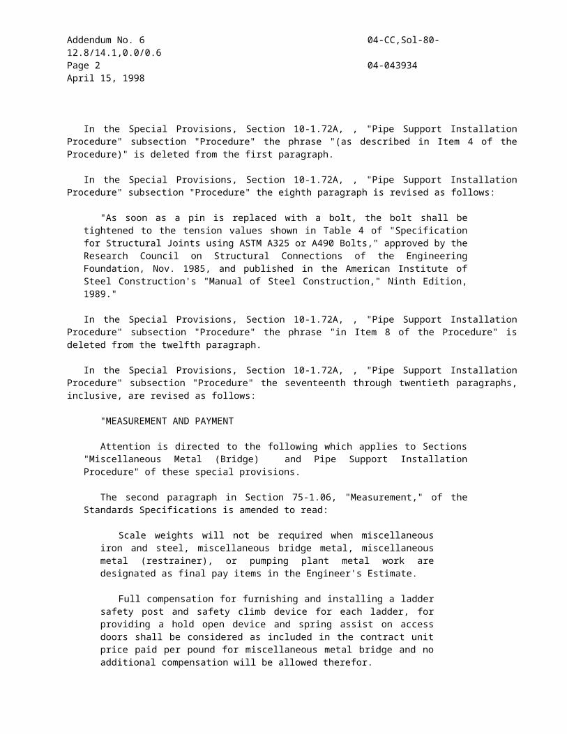
each be a minimum 1/2 inch high, and located on the left (street) side at the lower front corner. The TMCC shall have a message next to the name and model number in 1/2 inch high letters which states, "The bottom of this TMCC shall be ___ inches ± ___ inches above the ground at all points for proper impact performance." Any TMCC which is damaged or appears to be in poor condition shall not be used unless recertified by the manufacturer. The Engineer shall be the sole judge as to whether used TMCCs supplied under this contract need recertification. Each unit shall be certified by the manufacturer to meet the requirements for TMCCs in accordance with the standards established by the Transportation Laboratory Structures Research Section.
Approvals for new TMCC designs proposed as equal to the above approved models shall be in accordance with the procedures (including crash testing) established by the Transportation Laboratory Structures Research Section. For information regarding submittal of new designs for evaluation contact:
Transportation LaboratoryStructures Research SectionP.O. Box 191285900 Folsom BoulevardSacramento, CA 95819
New TMCCs proposed as equal to approved TMCCs or approved TMCCs determined by the Engineer to need recertification shall not be used until approved or recertified by the Transportation Laboratory Structures Research Section.
PAYMENT.--The contract lump sum price paid for traffic control system shall include full compensation for furnishing all labor (except for flagging costs), materials (including signs), tools, equipment and incidentals, and for doing all the work involved in placing, removing, storing, maintaining, moving to new locations, replacing and disposing of the components of the traffic control system as shown on the plans, as specified in the Standard Specifications and these special provisions, and as directed by the Engineer. Flagging costs will be paid for as provided in Section 12-2.02, "Flagging Costs," of the Standard Specifications.
The adjustment provisions in Section 4-1.03, "Changes," of the Standard Specifications, shall not apply to the item of traffic control system. Adjustments in compensation for traffic control system will be made only for increased or decreased traffic control system required by changes ordered by the Engineer and will be made on the basis of the cost of the increased or decreased traffic control necessary. Such adjustment will be made on a force account basis as provided in Section 9-1.03, "Force Account Payment," of the Standard Specifications for increased work, and estimated on the same basis in the case of decreased work.
Traffic control system required by work which is classed as extra work, as provided in Section 4-1.03D of
the Standard Specifications, will be paid for as a part of the extra work.10-1.19 TRAFFIC CONTROL (CROSSOVER DETOUR)
Traffic control (crossover detour) shall consist of traffic control in accordance with the details shown on the plans for Stage 2B and Stage 3B, as directed by the Engineer, the provisions of Section 12, "Construction Area Traffic Control Devices," of the Standard Specifications, the provisions under "Maintaining Traffic" and "Construction Area Signs" elsewhere in these special provisions and these special provisions.
The provisions in this section will not relieve the Contractor from the responsibility to provide such additional devices or take such measures as may be necessary to comply with the provisions in Section 7-1.09, "Public Safety," of the Standard Specifications.
If any component in the traffic control (crossover detour) is displaced, or ceases to operate or function as specified, from any cause, during the progress of the work, the Contractor shall immediately repair the component to its original condition or replace the component and shall restore the component to its original location.
The components of traffic control (crossover detour) include construction area signs, temporary crash cushion module, temporary railing (Type K), flashing arrow signs, Type III barricade, object markers, warning lights and cones.
Construction area signs, Type III barricade, temporary railing (Type K) and temporary crash cushion module shall conform to the provisions in Section "Construction Area Signs," "Barricades," "Temporary Railing," and "Temporary Crash Cushion Module" elsewhere in these special provisions.
Warning lights shall be furnished, placed and maintained at the locations shown on the plans or as directed by the Engineer.
If warning lights are displaced or are not in an upright position, from any cause, during the progress of the work, the Contractor shall immediately repair and repaint or replace the warning lights in their original locations.
At the end of each night's work, all warning light units shall be removed from the traveled way. If the Contractor so elects, the warning light units may be stored at selected central locations, approved by the Engineer, within the limits of the highway right of way. Full compensation for placing, removing and storing warning light units daily as the work progresses shall be considered as included in the contract unit price paid for traffic control (crossover detour) and no additional compensation will be allowed therefor.
Each warning light unit shall consist of a lighting unit, housing, batteries and mounting hardware. The units shall be assembled for a complete, self-contained, warning light which can be delivered to the site and mounted on barricades.
Warning lights on barricades shall be installed to a minimum mounting height of 36 inches to the bottom of the lens.
CONTRACT NO. 04-043934REISSUED PER ADDENDUM N0. 11 DATED JUNE 1, 1998
95

Warning lights are portable, lens directed, enclosed lights. The color of the lights emitted shall be yellow in a steady-burn mode.
Lights shall be maintained so as to be capable of being visible on a clear night from a distance of 3000 feet.
The lens shall be illuminated by means of electric lamp behind the lens and shall be externally illuminated by retro-reflective elements built into the lens.
The lens shall be bidirectional lens and shall not be less than seven inches in diameter, including a retro-reflector ring of approximately 1/2" width around a minimum of 300 of the periphery.
Lens shall be of one-piece construction of plastic.Housing is defined as the case containing the
batteries and circuitry. The housing shall be constructed of No. 18 U.S. Standard Gauge Steel or any other material which by engineering judgement is considered capable of withstanding considerable abuse. The case must be secured by a locking device.
The housing and the lens frame, if of corrodable metal, shall be properly cleaned, degreased and pretreated to promote adhesion. It shall be given one or more coats of enamel which, when dry, shall completely obscure the metal substrate. The enamel coating shall be of such quality that when the coated case is struck a light blow with a sharp tool, the paint shall not chip or crack, and if scratched with a knife shall not powder.
The case shall be so constructed and closed as to exclude moisture that would affect the specified operation of the light. The case shall have a weephole to allow the escape of moisture.
Photoelectric controls, if provided, shall keep the light operating whenever the ambient light falls below 215 Lux.
Warning lights shall be in accordance with the Institute of Transportation Engineers Purchase Specification for Flashing and Steady Burn Warning Lights or as approved by the Engineer.
The light distribution shall have a minimum lateral width of 9 degrees and a minimum vertical height of 5 degrees from the optical axis of the system. The luminous intensity shall not drop below 2.0 candelas during the first 168 hours of continuous burning. S.A.E. (Society of Automotive Engineers) Standard J 575, most recent edition, shall be used to test the intensity of the light. The specific intensity of the retroreflection at an observation angle of 0.2 degrees and a light incidence angle of zero (0) degrees shall not be less than 1.67 candelas/lux. Reflex-reflection shall be tested in accordance with the most recent edition of S.A.E. Standard J 594.
Warning lights furnished shall be tested in accordance with the latest revision of A.T.S.A (American Traffic Services Association) Test Procedure T-101.
If the light uses an incandescent lamp, the chromaticity of the lens color shall be defined by the trilinear coordinates of the C.I.E. Standards (Commission International d’Eclairage).When tested with illuminants from 2856K to 2366K, the lens color shall fall within the area of the Chromaticity Diagram
according to the 1931 C.I.E. Standard Observer defined by the following coordinates:
X Y Z0.543 0.452 0.0050.548 0.452 0.0000.584 0.411 0.0050.589 0.411 0.000
If the light uses other than an incandescent lamp, the light output shall be in the same range as the light obtained with the incandescent lamp and the specific lens.
The minimum relative luminous transmittance of the lens with illuminant at 2856 shall be 0.440.
The lens material shall be plastic capable of producing a lens that can meet the chromaticity and luminous transmission requirements of this specification. The lens material shall meet the test requirements set forth in the most recent edition of S.A.E. Standard J 576 (Society of Automotive Engineers, Inc. "Lighting Equipment and Photometric Tests") except that the exposure time and conditions (S.A.E. Standard, Paragraph 3.4.3) for the purpose of this standard shall be one year.
Warning lights shown on the plans as part of a traffic control system shall be considered as part of that traffic control (crossover detour) and will be paid for as specified under "Traffic Control(Crossover Detour)," elsewhere in these special provisions.
MEASUREMENT AND PAYMENT.--Traffic control (crossover detour) will be measured by each time the crossover detour is used.
The contract unit price paid for traffic control (crossover detour) shall include full compensation for furnishing all labor, materials (including signs), tools, equipment and incidentals, and for doing all the work involved in placing, removing, storing, maintaining, moving to new locations, replacing, resetting and disposing of the components of the traffic control (crossover detour) as shown on the plans, as specified in the Standard Specifications and these special provisions, and as directed by the Engineer.
The adjustment provisions in Section 4-1.03, "Changes," of the Standard Specifications, shall not apply to the item of traffic control (crossover detour). Adjustments in compensation for traffic control (crossover detour) will be made only for increased or decreased traffic control (crossover detour) required by changes ordered by the Engineer and will be made on the basis of the cost of the increased or decreased traffic control (crossover detour). Such adjustment will be made on a force account basis as provided in Section 9-1.03, "Force Account Payment," of the Standard Specifications for increased work, and estimated on the same basis in the case of decreased work.
Traffic control (crossover detour) required by work which is classed as extra work, as provided in Section 4-1.03D of the Standard Specifications, will be paid for as a part of the extra work.
CONTRACT NO. 04-043934REISSUED PER ADDENDUM N0. 11 DATED JUNE 1, 1998
96

Traffic control for lane and ramp closures required for the crossover detour shall be paid for as part of the item for traffic control system, elsewhere in these special provisions.10-1.20 TEMPORARY PAVEMENT DELINEATION
Temporary pavement delineation shall be furnished, placed, maintained and removed in accordance with the provisions in Section 12-3.01, "General," of the Standard Specifications and these special provisions. Nothing in these special provisions shall be construed as to reduce the minimum standards specified in the Manual of Traffic Controls published by the Department or as relieving the Contractor from the responsibilities specified in Section 7-1.09, "Public Safety," of the Standard Specifications.
GENERAL.--Whenever the work causes obliteration of pavement delineation, temporary or permanent pavement delineation shall be in place prior to opening the traveled way to public traffic. Laneline or centerline pavement delineation shall be provided at all times for traveled ways open to public traffic. On multilane roadways (freeways and expressways) edgeline delineation shall be provided at all times for traveled ways open to public traffic.
All work necessary, including any required lines or marks, to establish the alignment of temporary pavement delineation shall be performed by the Contractor. Surfaces to receive temporary pavement delineation shall be dry and free of dirt and loose material. Temporary pavement delineation shall not be applied over existing pavement delineation or other temporary pavement delineation. Temporary pavement delineation shall be maintained until superseded or replaced with a new pattern of temporary pavement delineation or permanent pavement delineation.
Temporary pavement markers and removable traffic tape which is applied to the final layer of surfacing or existing pavement to remain in place or which conflicts with a subsequent or new traffic pattern for the area shall be removed when no longer required for the direction of public traffic, as determined by the Engineer.
TEMPORARY LANELINE AND CENTERLINE DELINEATION.--Whenever lanelines or centerlines are obliterated and temporary pavement delineation to replace the lines is not shown on the plans, the minimum laneline and centerline delineation to be provided for that area shall be temporary reflective pavement markers placed at longitudinal intervals of not more than 24 feet. The temporary reflective pavement markers shall be the same color as the laneline or centerline the pavement markers replace. Temporary reflective pavement markers shall be, at the option of the Contractor, one of the temporary pavement markers listed for short term day/night use (14 days or less) or long term day/night use (6 months or less) in "Prequalified and Tested Signing and Delineation Materials" elsewhere in these special provisions.
Temporary reflective pavement markers shall be placed in accordance with the manufacturer's instructions
and shall be cemented to the surfacing with the adhesive recommended by the manufacturer, except epoxy adhesive shall not be used to place pavement markers in areas where removal of the pavement markers will be required.
Temporary laneline or centerline delineation consisting entirely of temporary reflective pavement markers placed on longitudinal intervals of not more than 24 feet, shall be used on lanes opened to public traffic for a maximum of 14 days. Prior to the end of the 14 days the permanent pavement delineation shall be placed. If the permanent pavement delineation is not placed within the 14 days, the Contractor shall provide additional temporary pavement delineation and the cost thereof shall be borne by the Contractor. The additional temporary pavement delineation to be provided shall be equivalent to the pattern specified for the permanent pavement delineation for the area, as determined by the Engineer.
Full compensation for furnishing, placing, maintaining and removing the temporary reflective pavement markers, used for temporary laneline and centerline delineation for those areas where temporary laneline and centerline delineation is not shown on the plans and for providing equivalent patterns of permanent traffic lines for those areas when required, shall be considered as included in the contract prices paid for the items of work that obliterated the laneline and centerline pavement delineation and no separate payment will be made therefor.
TEMPORARY EDGELINE DELINEATION.--On multilane roadways (freeways and expressways) whenever edgelines are obliterated and temporary pavement delineation to replace those edgelines is not shown on the plans, the edgeline delineation to be provided for those areas adjacent to lanes open to public traffic shall be as follows:
Temporary pavement delineation for right edgelines shall, at the option of the Contractor, consist of either a solid 4-inch wide traffic stripe of the same color as the stripe the temporary edgeline delineation replaces, or traffic cones, portable delineators or channelizers placed at longitudinal intervals not to exceed 100 feet.
Temporary pavement delineation for left edgelines shall, at the option of the Contractor, consist of either solid 4-inch wide traffic stripe of the same color as the stripe the temporary edgeline delineation replaces, or traffic cones, portable delineators or channelizers
CONTRACT NO. 04-043934REISSUED PER ADDENDUM N0. 11 DATED JUNE 1, 1998
97

placed at longitudinal intervals not to exceed 100 feet; or temporary reflective pavement markers placed at longitudinal intervals of not more than 6 feet. Temporary pavement markers used for temporary left edgeline delineation shall be one of the types of temporary pavement markers listed for short term day/night use (14 days or less) or long term day/night use (6 months or less) in "Prequalified and Tested Signing and Delineation Materials" elsewhere in these special provisions.
Four-inch wide traffic stripe placed for temporary edgeline delineation which will require removal shall conform to the requirements of temporary traffic stripe (tape) specified herein. Where removal of the 4-inch wide traffic stripe will not be required painted traffic stripe conforming to the requirements of temporary traffic stripe (paint) specified herein may be used. The quantity of temporary traffic stripe (tape) or temporary traffic stripe (paint) used for this temporary edgeline delineation will not be included in the quantities of tape or paint to be paid for.
The lateral offset for traffic cones, portable delineators or channelizers used for temporary edgeline delineation shall be as determined by the Engineer. If traffic cones or portable delineators are used as temporary pavement delineation for edgelines, the Contractor shall provide personnel to remain at the jobsite to maintain the cones or delineators during all hours of the day that they are in use.
Channelizers used for temporary edgeline delineation shall be the surface mounted type and shall be orange in color. Channelizer bases shall be cemented to the pavement in the same manner provided for cementing pavement markers to pavement in the section of these special provisions entitled "Pavement Markers," except epoxy adhesive shall not be used to place channelizers on the top layer of pavement. Channelizers shall be, at the Contractor's option, one of the surface mount types (36") listed in "Prequalified and Tested Signing and Delineation Materials" elsewhere in these special provisions.
Temporary edgeline delineation shall be removed when no longer required for the direction of public traffic, as determined by the Engineer.
The quantity of channelizers used as temporary edgeline delineation will not be included in the quantity of channelizers to be paid for. Full compensation for furnishing, placing, maintaining and removing the temporary edgeline delineation for those areas where temporary edgeline delineation is not shown on the plans shall be considered as included in the contract prices paid for the items of work that obliterated the edgeline
pavement delineation and no separate payment will be made therefor.
TEMPORARY TRAFFIC STRIPE (TAPE).--Temporary traffic stripe consisting of removable traffic stripe tape shall be applied at the locations shown on the plans. The temporary traffic stripe tape shall be complete in place at the location shown, prior to opening the traveled way to public traffic.
Removable traffic stripe tape shall be the temporary removable type traffic stripe tape listed in "Prequalified and Tested Signing and Delineation Materials" elsewhere in these special provisions.
Removable traffic stripe tape shall be applied in accordance with the manufacturer's installation instructions and shall be rolled slowly with a rubber tired vehicle or roller to ensure complete contact with the pavement surface. Traffic stripe tape shall be applied straight on tangent alignment and on a true arc on curved alignment. Traffic stripe tape shall not be applied when the air or pavement temperature is less than 50° F., unless the installation procedures to be used are approved by the Engineer, prior to beginning installation of the tape.
TEMPORARY PAVEMENT MARKERS.--Temporary pavement markers shall be applied at the locations shown on the plans. The pavement markers shall be applied complete in place at the location shown, prior to opening the traveled way to public traffic.
Temporary pavement markers shown on the plans shall be, at the option of the Contractor, one of the temporary reflective pavement markers for long term day/night use (6 months or less) listed in "Prequalified and Tested Signing and Delineation Materials" elsewhere in these special provisions.
Temporary pavement markers shall be placed in accordance with the manufacturer's instructions and shall be cemented to the surfacing with the adhesive recommended by the manufacturer, except epoxy adhesive shall not be used in areas where removal of the pavement markers will be required.
Where the temporary pavement delineation shown on the plans for lanelines or centerlines consists entirely of a pattern of broken traffic stripe and pavement markers, the Contractor may use groups of the temporary reflective pavement markers for long term day/night use (6 months or less) listed in "Prequalified and Tested Signing and Delineation Materials" elsewhere in these special provisions, in place of the temporary traffic stripe tape or painted temporary traffic stripe. The groups of pavement markers shall be spaced as shown on the plans for a similar pattern of permanent traffic line, except pavement markers shown to be placed in the gap between the broken traffic stripe shall be placed as part of the group to delineate the pattern of broken temporary traffic stripe. The kind of laneline and centerline delineation selected by the Contractor shall be continuous within a given location. Payment for temporary pavement markers used in place of temporary traffic stripe will be made on the basis of the theoretical quantities of temporary traffic stripe (tape), temporary
CONTRACT NO. 04-043934REISSUED PER ADDENDUM N0. 11 DATED JUNE 1, 1998
98

traffic stripe (paint) and temporary pavement markers required for the pattern the pavement markers replace.
Reflective pavement markers conforming to the requirements of "Pavement Markers" of these special provisions may be used in place of temporary reflective pavement markers for long term day/night use (6 months or less) except at locations to simulate patterns of broken traffic stripe. Placement of the reflective pavement markers used for temporary pavement markers shall conform to said section "Pavement Markers" of these special provisions except; the waiting period requirements before placing the pavement markers on new asphalt concrete surfacing as specified in Section 85-1.06, "Placement," of the Standard Specifications shall not apply and epoxy adhesive shall not be used to place pavement markers in areas where removal of the pavement markers will be required.
MEASUREMENT AND PAYMENT.--Temporary traffic stripe (tape) will be measured and paid for by the linear foot, measured along the line of the stripe, with deductions for gaps in broken traffic stripes. Double and 8-inch temporary traffic stripes, shown on the plans as tape, will be measured as 2 temporary traffic stripes (tape).
Temporary pavement markers, shown on the plans, will be measured and paid for as units in the same manner specified for reflective pavement markers as provided in Section 85-1.08, "Measurement," and Section 85-1.09, "Payment," of the Standard Specifications. Temporary pavement markers, used for temporary laneline and centerline delineation for areas which are not shown on the plans will not be included in the quantities of temporary pavement markers to be paid for. Full compensation for removing temporary pavement markers, when no longer required, shall be considered as included in the contract unit price paid for temporary pavement marker and no separate payment will be made therefor.
The contract price paid per linear foot for temporary traffic stripe (tape) shall include full compensation for furnishing all labor, materials, tools, equipment, and incidentals, and for doing all the work involved in applying, maintaining and removing the temporary traffic stripe tape, complete in place, as shown on the plans, as specified in the Standard Specification and these special provisions, and as directed by the Engineer.
10-1.21 BARRICADESBarricades shall be furnished, placed, and
maintained at the locations designated by the Engineer, shown on the plans, or specified and shall conform to the provisions in Section 12, "Construction Area Traffic Control Devices," of the Standard Specifications and these special provisions.
Type II reflective sheeting for stripes on barricade rail faces shall conform to the requirements specified under "Prequalified and Tested Signing and Delineation Materials," elsewhere in these special provisions.
Construction area sign and marker panels conforming to the requirements in Section 12-3.06, "Construction Area Signs," of the Standard
Specifications shall be installed on barricades as directed by the Engineer at the locations shown on the plans.
Sign panels for construction area signs and marker panels installed on barricades shall conform to the requirements of sign panels for stationary mounted signs in Section 12-3.06A, "Stationary Mounted Signs," of the Standard Specifications.
Full compensation for furnishing, installing, maintaining, and removing construction area signs and markers on barricades shall be considered as included in the contract unit price or prices paid for the type or types of barricade and no separate payment will be made therefor.
Barricades shown on the plans as part of a traffic control system or traffic control (crossover detour) will be paid for as provided in "Traffic Control System for Lane Closure" or "Traffic Control (Crossover Detour)," elsewhere in these special provisions, and will not be included in counts for payment for barricades.
10-1.22 PORTABLE CHANGEABLE MESSAGE SIGN
Portable changeable message signs shall be furnished, placed, operated, and maintained at locations shown on the plans and shall conform to the provisions of Section 12, "Construction Area Traffic Control Devices," of the Standard Specifications and these special provisions.
Attention is directed to "Maintaining Traffic" of these special provisions concerning the use of the portable changeable message signs.
10-1.23 TEMPORARY RAILINGTemporary railing (Type K) shall be placed at the
locations shown on the plans, specified in these special provisions or in the Standard Specifications or ordered by the Engineer, and shall conform to the provisions in Section 12, "Construction Area Traffic Control Devices," of the Standard Specifications and these special provisions.
Temporary railing (Type K) fabricated prior to January 1, 1993, with one longitudinal No. 5 reinforcing steel bar near the top in lieu of the 2 longitudinal No. 5 reinforcing steel bars near the top, as shown on the plans, may be used.
The Contractor's attention is directed to the provisions in "Public Safety" and "Order of Work" elsewhere in these special provisions.
Temporary railing (Type K) placed in accordance with the provisions in "Public Safety" elsewhere in these special provisions will not be measured nor paid for.
Reflectors and adhesive for temporary railing (Type K) shall be furnished by the Contractor. Reflectors shall be, at the option of the Contractor, one of the non-impactable type concrete barrier markers listed in "Prequalified and Tested Signing and Delineation Materials" elsewhere in these special provisions. Adhesive for mounting reflectors shall be per manufacturers recommendations and as approved by the Engineer.
Full compensation for reflectors and adhesive shall be considered as included in the contract price paid per
CONTRACT NO. 04-043934REISSUED PER ADDENDUM N0. 11 DATED JUNE 1, 1998
99

linear foot for temporary railing (Type K) and no separate payment will made therefor.
Temporary railing (Type K) shown on the plans as part of the traffic control (crossover detour) will be measured and paid for as provided in "Traffic Control (Crossover Detour)," elsewhere in these special provisions and will not be included in counts for payment for temporary railing (Type K).
10-1.24 CHANNELIZERSChannelizers shall be surface mounted type and
shall be furnished, placed and maintained at the locations shown on the plans and shall conform to the provisions in Sections 12, "Construction Area Traffic Control Devices," of the Standard Specifications and these special provisions.
Channelizers shall conform to the provisions in "Prequalified and Tested Signing and Delineation Materials," elsewhere in these special provisions.
Channelizer posts shall be orange in color.At the option of the Contractor, channelizer bases
may be cemented to the pavement using hot melt bitumen adhesive and in the same manner provided for cementing pavement markers to pavement in the section of these special provisions entitled "Pavement Markers."10-1.25 TEMPORARY CRASH CUSHION MODULE
This work shall consist of furnishing, installing and maintaining sand filled temporary crash cushion modules in groupings or arrays at each location shown on the plans, specified in the special provisions or directed by the Engineer. The grouping or array of sand filled modules shall form a complete sand filled temporary crash cushion in accordance with the details shown on the plans and these special provisions.
Attention is directed to "Public Safety" and "Order of Work" of these special provisions.
GENERAL.--Whenever the work or the Contractor's operations establishes a fixed obstacle, the exposed fixed obstacle shall be protected with a sand filled temporary crash cushion. The sand filled temporary crash cushion shall be in place prior to opening the lanes adjacent to the fixed obstacle to public traffic.
Sand filled temporary crash cushions shall be maintained in place at each location, including times when work is not actively in progress. Sand filled temporary crash cushions may be removed during a work period for access to the work provided that the exposed fixed obstacle is 15 feet or more from a lane carrying public traffic and the temporary crash cushion is reset to protect the obstacle prior to the end of the work period in which the fixed obstacle was exposed. When no longer required, as determined by the Engineer, sand filled temporary crash cushions shall be removed from the site of the work.
MATERIALS.--At the Contractor's option, the modules for use in sand filled temporary crash cushions shall be either of the following types or equal:
Energite Inertial Modules
Manufacturer: Distributor(Northern):
Energy Absorption Systems, Inc.
Traffic Control Service, Inc.
One East Wacker Drive 8585 Thys CourtChicago, IL 60601-2076 Sacramento, CA 95828Telephone (312) 467-6750 Telephone (800) 884-8274
FAX (916) 387-9734
Distributor(Southern):
Traffic Control Service, Inc.
1881 Betmor LaneAnaheim, CA 92805Telephone (800) 222-8274
or Fitch Inertial Modules
National Distributor: Distributor:
Roadway Safety Service, Inc.
700-3 Union ParkwayRonkonkoma, NY 11779
Singletree Sales Company1533 Berger DriveSan Jose, CA 95112Telephone (800) 822-7735
Modules contained in each temporary crash cushion shall be of the same type at each location. The color of the modules shall be the standard yellow color as furnished by the vendor, with black lids. The modules shall exhibit good workmanship free from structural flaws and objectionable surface defects. The modules need not be new. Good used undamaged modules conforming to color and quality of the types specified above may be utilized. If used Fitch modules requiring a seal are furnished, the top edge of the seal shall be securely fastened to the wall of the module by a continuous strip of heavy duty tape.
Modules shall be filled with sand in accordance with the manufacturer's directions, and to the sand capacity in pounds for each module as shown on the plans. Sand for filling the modules shall be clean washed concrete sand of commercial quality. At the time of placing in the modules, the sand shall contain not more than 7 percent water, as determined by California Test 226.
Modules damaged due to the Contractor's operations shall be repaired immediately by the Contractor at his expense. Modules damaged beyond repair, as determined by the Engineer, due to the Contractor's operations shall be removed and replaced by the Contractor at his expense.
INSTALLATION.--Temporary crash cushion modules shall be placed on movable pallets or frames conforming to the dimensions shown on the plans. The pallets or frames shall provide a full bearing base beneath the modules. The modules and supporting pallets or frames shall not be moved by sliding or skidding along the pavement or bridge deck.
CONTRACT NO. 04-043934REISSUED PER ADDENDUM N0. 11 DATED JUNE 1, 1998
100

A Type R or P marker panel shall be attached to the front of the crash cushion as shown on the plans, when the closest point of crash cushion array is within 12 feet of the traveled way. The marker panel, when required, shall be firmly fastened to the crash cushion with commercial quality hardware or by other methods approved by the Engineer.
At the completion of the project, temporary crash cushion modules, sand filling, pallets or frames, and marker panels shall become the property of the Contractor and shall be removed from the site of the work. Temporary crash cushion modules shall not be installed in permanent work.
MEASUREMENT AND PAYMENT.--Temporary crash cushion modules will be measured by the unit determined from the actual count of modules used in the work or ordered by the Engineer at each location. Temporary crash cushion modules placed in accordance with the provisions in "Public Safety" elsewhere in these
CONTRACT NO. 04-043934REISSUED PER ADDENDUM N0. 11 DATED JUNE 1, 1998
101

ENGINEER'S ESTIMATE04-043934
Item Item Code
Item Unit of Measure
Estimated Quantity
Unit Price Item Total
201(S)
011332 SIGNAL AND LIGHTING (STAGE CONSTRUCTION- LOCATION 2)
LS LUMP SUM LUMP SUM
202(S)
861504 MODIFY LIGHTING AND SIGN ILLUMINATION
LS LUMP SUM LUMP SUM
203(S)
047001 SEISMIC MONITORING SYSTEM LS LUMP SUM LUMP SUM
204 046846 INSTALL SEISMIC MONITORING CASING (DOWNHOLE)
LF 225
205 011914 TIME RELATED OVERHEAD WDAY 540
206 012415 ROADWAY EXCAVATION (CONTAMINATION MATERIAL)
CY 2,130
207 012416 DRAINAGE EXCAVATION (CONTAMINATED)
CY 890
208 012417 SANITARY SEWER EXCAVATION(CONTAMINATED)
CY 190
209 012419 MISCELLANEOUS METAL(PIPE SUPPORT DETAIL 8)
EA 2
210 012420 MISCELLANEOUS METAL(PIPE SUPPORT DETAIL 9)
EA 1
211 013222 ESTABLISH MARINE ACCESS LS LUMP SUM LUMP SUM
212 999990 MOBILIZATION LS LUMP SUM LUMP SUM
TOTAL BID:
13

REVISED PER ADDENDUM NO. 11 DATED JUNE 1, 1998