Embed Size (px)
Citation preview

June 29, 2021
Addendum No. 3
Fort Wayne Community Schools - Elementary and Secondary Emergency Education Relief (ESSER) Projects
Guaranteed Energy Savings Project
Heating, Ventilation and Air Conditioning (HVAC) Improvements at Various Locations
RFP Dated May 18, 2021 Documents issued May 18, 2021 for Request for Proposal / Guaranteed Energy Savings Project – Heating, Ventilation and Air Conditioning (HVAC) Improvements at Various Locations are hereby revised as indicated.
ITEM 1. PREVAILING REQUIREMENTS
1.1 Specifications Section 005000 Request for Proposals:
When listed in Section 005000 Request for Proposals, specific requirements listed shall supersede conflicting requirements that may be listed in FWCS design standards.
ITEM 2. DECENTRALIZED HVAC EQUIPMENT DESIGN STANDARDS UPDATES
2.1 Specifications Section 238000 Decentralized HVAC Equipment, Requirements
for Unit Ventilators and Accessories, Paragraphs c. - g. Paragraphs c. – g. are changed as follows:
a. Centrifugal Supply Air Fans i. Fans shall be forwardly curved double width-double inlet, with
common shaft mounted on a removable fan board, directly connected to motor.
ii. Motor shall be permanently lubricated, multispeed, resiliently mounted on motor board.
1. Motor shall be an Electrically Commutated Motor (ECM) that is configured for local control of the fan speed by a local potentiometer know and/or and input for the building

June 29, 2021
management system (1-10 VDC or 4-20 mA) signal. 2. Do not preprogram motor for a fixed airflow or static pressure
condition. Program shall allow for field selection of operation point between the minimum and maximum safe operating points for the fan.
iii. Provide a toggle-type disconnect switch with each unit to provide electrical disconnect of power to all components.
a. Chilled Water Cooling and Hot Water Heating Coils iv. Coils shall consist of seamless copper tubes with bonded aluminum
fins. Coils shall be designed for 300 psi w.p. v. An automated air vent shall be provided on each coil.
b. Dampers: vi. Outside Air: Provide low leak return air dampers with edge seals
arranged for automatic operation, modulating from zero to 100% outside air intake.
c. Condensate Drain System: The condensate drain system shall include a condensate drain pan under the cooling coil, pitched to drain, and an auxiliary drain pan under the coil connections. Provide auxiliary drain pan and/or condensate high limit fan cutoff as required by code. All drain pans to be stainless steel.
d. Control System: Controls shall be a complete electronic direct digital controls system supplied to factory from Owner’s selected vendor (Automated Logic Corporation). TCC shall supply wiring diagram to the manufacturer.
vii. Factory shall install and wire all controls internal to the unit, including the following:
1. Control valves, provided by TCC and installed by TCC in the field.
2. Damper actuators, provided by TCC and installed by the unit manufacturer.
3. Sensors, provided by the TCC and installed by the unit manufacturer.
4. Freezestats, provided by the TCC and installed by the unit manufacturer.
a. 1 lineal foot of element for every 1 sq. ft. of coil surface. 5. Supply fan variable speed controls, provided and installed by
unit manufacturer. viii. Control boards, provided by TCC and installed by unit manufacturer.

June 29, 2021
ITEM 3. TEMPERATURE CONTROL STANDARDS
3.1 Specifications Section 230000a FWCS Automated Logic Standards Replace specifications Section 230000a FWCS Automated Logic Standards with
the attached, updated standards dated March 4, 2021, and including typical Unit Ventilator Sequence of Operation dated March 4, 2021.
END OF ADDENDUM NO. 3
238000 - 1 Last Updated: Decentralized HVAC Equipment June 28, 2021
SECTION 238000
DECENTRALIZED HVAC EQUIPMENT
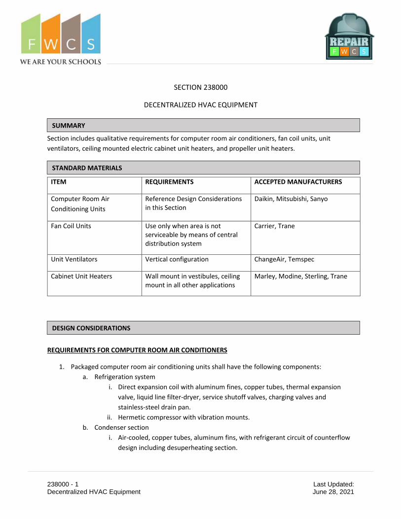
Section includes qualitative requirements for computer room air conditioners, fan coil units, unit ventilators, ceiling mounted electric cabinet unit heaters, and propeller unit heaters.
ITEM REQUIREMENTS ACCEPTED MANUFACTURERS
Computer Room Air Conditioning Units
Reference Design Considerations in this Section
Daikin, Mitsubishi, Sanyo
Fan Coil Units Use only when area is not serviceable by means of central distribution system
Carrier, Trane
Unit Ventilators Vertical configuration ChangeAir, Temspec
Cabinet Unit Heaters Wall mount in vestibules, ceiling mount in all other applications
Marley, Modine, Sterling, Trane
REQUIREMENTS FOR COMPUTER ROOM AIR CONDITIONERS
1. Packaged computer room air conditioning units shall have the following components: a. Refrigeration system
i. Direct expansion coil with aluminum fines, copper tubes, thermal expansion valve, liquid line filter-dryer, service shutoff valves, charging valves and stainless-steel drain pan.
ii. Hermetic compressor with vibration mounts. b. Condenser section
i. Air-cooled, copper tubes, aluminum fins, with refrigerant circuit of counterflow design including desuperheating section.
SUMMARY
DESIGN CONSIDERATIONS
STANDARD MATERIALS

238000 - 2 Last Updated: Decentralized HVAC Equipment June 28, 2021
ii. Fan shall be double inlet, direct drive with 3-speed motor and low limit ambient control to prevent evaporator freezeup.
c. Reheat Section: Electric reheat coils shall be low-density, tubular type elements, with UL approved safety switches.
d. Condensate Drain System: The condensate drain system shall include a condensate pump with integral float switch, pump/motor assembly, and reservoir.
e. Control System: The control system shall be solid state and shall include a remote thermostat and shutoff switch for field installation.
f. Warranty: The unit compressor shall have an extended 5 year parts and labor warranty which starts at substantial completion.
REQUIREMENTS FOR FAN COIL UNITS AND ACCESSORIES
1. Fan coil units shall have the following components: a. Cabinet and frame construction
i. Welded, heavy gauge galvanized steel frame. ii. Zinc-coated steel with primer coat and baked enamel finish.
iii. Minimum 2 inch, 2 pound density fiber insulation. iv. Hinged filter and grille for access. v. The valve compartment housing the heating and chilled water control valves
shall be oversized to provide adequate space to properly maintain the control valves. Minimum width of valve compartment shall be 24 inches. The valve compartment extension shall match the unit cabinet construction and finish.
b. Filters: Provide filter frames and filters from Hometown Filter. c. Centrifugal Supply Air Fan: Fan shall be forwardly curved double width-double inlet,
with common shaft mounted on a removable fan board, driven by a three-speed permanent split capacitor motor having built-in overload protection.
d. Chilled Water Cooling and Hot Water Heating Coils i. Coils shall consist of seamless copper tubes with bonded aluminum fins. Coils
shall be designed for 300 psi w.p. ii. A manual air vent shall be provided on each coil.
e. Condensate Drain System: The condensate drain system shall include a condensate drain pan under the cooling coil, pitched to drain, and an auxiliary drain pan under the coil connections. Provide auxiliary drain pan and/or condensate high limit fan cutoff as required by code.
f. Control System: The control system call be a complete system of electronic direct digital controls.

238000 - 3 Last Updated: Decentralized HVAC Equipment June 28, 2021
REQUIREMENTS FOR UNIT VENTILATORS AND ACCESSORIES
1. Unit ventilators shall have the following components: a. The cabinet shall be constructed of galvanized steel with removable front panel.
i. Mounting: Wall installation with wall sleeve. ii. Finish: Baked enamel over heavy (18 gauge) phosphatized galvanized steel.
iii. Subbase: Enameled steel. iv. Louvers: Extruded aluminum, architectural style grille with horizontal louvers
and baked enamel finish. v. Discharge grille and access door: Extruded aluminum.
vi. The valve compartment housing the heating and chilled water control valves shall be oversized to provide adequate space to properly maintain the control valves. This valve compartment extension shall match the unit cabinet construction and finish, and be provided with a hinged front access panel for pipe access.
b. Filters: Provide filter frames and filters from Hometown Filter. c. Centrifugal Supply Air Fans
i. Fans shall be forwardly curved double width-double inlet, with common shaft mounted on a removable fan board, directly connected to motor.
ii. Motor shall be permanently lubricated, multispeed, resiliently mounted on motor board.
1. Motor shall be an Electrically Commutated Motor (ECM) that is configured for local control of the fan speed by a local potentiometer know and/or and input for the building management system (1-10 VDC or 4-20 mA) signal.
2. Do not preprogram motor for a fixed airflow or static pressure condition. Program shall allow for field selection of operation point between the minimum and maximum safe operating points for the fan.
iii. Provide a toggle-type disconnect switch with each unit to provide electrical disconnect of power to all components.
d. Chilled Water Cooling and Hot Water Heating Coils i. Coils shall consist of seamless copper tubes with bonded aluminum fins. Coils
shall be designed for 300 psi w.p. ii. An automated air vent shall be provided on each coil.
e. Dampers: i. Outside Air: Provide low leak return air dampers with edge seals arranged for
automatic operation, modulating from zero to 100% outside air intake.

238000 - 4 Last Updated: Decentralized HVAC Equipment June 28, 2021
f. Condensate Drain System: The condensate drain system shall include a condensate drain pan under the cooling coil, pitched to drain, and an auxiliary drain pan under the coil connections. Provide auxiliary drain pan and/or condensate high limit fan cutoff as required by code. All drain pans to be stainless steel.
g. Control System: Controls shall be a complete electronic direct digital controls system supplied to factory from Owner’s selected vendor (Automated Logic Corporation). TCC shall supply wiring diagram to the manufacturer.
i. Factory shall install and wire all controls internal to the unit, including the following:
1. Control valves, provided by TCC and installed by TCC in the field. 2. Damper actuators, provided by TCC and installed by the unit
manufacturer. 3. Sensors, provided by the TCC and installed by the unit manufacturer. 4. Freezestats, provided by the TCC and installed by the unit manufacturer.
a. 1 lineal foot of element for every 1 sq. ft. of coil surface. 5. Supply fan variable speed controls, provided and installed by unit
manufacturer. ii. Control boards, provided by TCC and installed by unit manufacturer.
REQUIREMENTS FOR ELECTRIC CABINET UNIT HEATERS
1. Cabinets shall be formed steel suitable for wall mounting (flush mount preferred unless existing conditions require semi-recessed) or recessed ceiling mounting. Provide with stamped grilles for air inlet and outlet (location dependent on style selected).
2. Coils shall be constructed of nickel chromium wire in metallic sheath with fins no closer than 0.16 inches and free from expansion noise and 60-Hz hum.
3. Fans shall be forward curved centrifugal direct drive. 4. Provide with disconnect switch, coil relay switches, and fan speed controller switch. 5. Provide with fan and electric coil circuit protection. 6. Provide factory enamel finish. 7. Provide tie in to electronic direct digital controls system.
END OF SECTION

1
FWCS Requirements 3-4-2021
Before we bring any new equipment on-line the Tech in charge of the project will add his cell number and the field supervisor’s number to the alarm action of the building they are working on. they will set up all alarms for the project to be sent to their phones.
Graphic Standards:
WebCTRL Summary Page: - Current version of FWCS Standards and sequences of operations
Building Summary Page:
- OAT & RH if applicable - HW & CHW Plant or Central Plant Links - Links to RTU Summary Page - Loop Temp Supply for Dual Systems - HW Set Point - Summer/Winter Switch condition - Phase Loss - Temps Cooler, Freezer, HW, CHW, Domestic HW - High Water Condition - Link to as-built’s - All links and temps need to show at the top left side of the page when pulled up. - The LGR and AAR’s location will be shown on the building summary page
Geo Page Layout:
- Areas - Area AHU Summary Page - Diamonds where AHU’s are actually located - AHU’s and RTU’s will be labeled by Equipment and Location that is served (AHU 1 Gym)

2
Geo Page Layout: - All links and temps to be on the top left hand of page if possible.
Programming Standards:
- Global Winter/Summer switch where applicable. ON=Winter – OFF=Summer - All integrations are to be BACnet MSTP - Chiller, Boilers, MDP integrations are ok all other integrations need to be approved by FWCS - FW Latitude will be set to 41.09 and Longitude of -85.18
Alarm Standards:
- There will be a folder on the desktop of the FWCS EMS01 server that will contain standard programs that will be accessed anytime we are creating new databases for FWCS. This will be done to ensure that we use the “standard programs” that have been agreed to.
- High Water and Phase Loss and domestic temp alarms will be sent to the FWCS supervisor over electrical, plumbing, and general maintenance.

3
- The only alarms that will have the return to normal will be HW Temp, domestic HW, CHW Temps, Phase Loss, and freezer cooler temps
- Elementary domestic hot water high temp will be set to 115 degrees and will have a time delay of 5 minutes before going into alarm.
- Elementary domestic hot water low temp will be set to 95 degrees and will have a time delay of 5 minutes before going into alarm.
- High Schools and Middle Schools domestic hot water high temp will be set to 140 degrees and will have a 10 minute delay before going into alarm.
- Cooler high temp will be set to 45 degrees with a time delay of 60 minutes before going into alarm.
- Cooler low temp will be set to 32 degrees with a time delay of 20 minutes before going into alarm.
- Freezer high temp will be set to 25 degrees with a time delay of 60 minutes before going into alarm.
- Freezer low temp will be set to -15 degrees with a time delay of 20 minutes before going into alarm.
- MDF high alarm temp will be set to 80 degrees with a time delay of 20 minutes Other alarms:
- Phase Loss - Freezer/Cooler - High Water/Sump alarm - Domestic HW - Air Compressor Fail - MDF High Temp - Refrigerant Alarms
Install Standards:
- Panel tags on any mounted panels larger than 11 x 17. Tags will have Device Served, Controller, and Controller Address. (AHU 2, SE6104a, CM 02).
- As-builts mounted in cabinets when completed. - Green conduit w green box covers. - All steel fittings with plastic sleeves (no pot metal). - ADA compliance for t-stat heights. - All wire ran in open plenum will be ran in bridal rings supported every 5 feet. - All wall penetrations have to be sleeved and fire calked. Plastic bushings on the ends of sleeve. - If you use an existing penetration to run your cable through it is your responsibility to
seal the hole - All installation quotes will include all controls demo including pneumatic demo and any
plates or covers required to cover openings left due to the removal of old controls. - No splicing of any wire is allowed unless approved by the field supervisor. If splice is
approved its location must be indicated on as-builts and customer must be made aware of it upon completion of work.

4
- As-builts control drawings will be viewable on the summary page of each building. - Ceiling needs to be labeled for any control devices above ceiling.
Required points to monitor in every building with ALC These points listed below are mandatory to monitor in all buildings when we install new controls. Unless FWCS directs otherwise.
- Phase Loss - High Water - All freezer/cooler except for rolling coolers (milk coolers) - MDF room temps - EF in special needs assisted restrooms - Parking lot lights (need to have programing to shut down with schedule and added to snow plow
app) Wall packs will not be controlled by ALC. - Domestic Hot water temps
Changes to all the ALC Standards will only be made by the ALC Field Supervisor over the FWCS projects. Any changes will have to be submitted by either the FWCS supervisor of mechanical maintenance or the ALC Field Supervisor to the FWCS manager of maintenance and operations for approval. All standards have been given as a directive by FWCS and all controls must meet these standards.

Unit Ventilator Sequence of Operation 3-4-2021 Run Conditions - Scheduled: The unit will run according to a user definable time schedule in the following modes:
o Occupied Mode: The unit will maintain
A 74°F (adj.) cooling setpoint A 70°F (adj.) heating setpoint.
o Unoccupied Mode (night setback): The unit will maintain A 80°F (adj.) cooling setpoint. A 62°F (adj.) heating setpoint. Optimal start will be set to 0.
Freeze Protection: Freezestats will not have a hard wired shut down it is to be a software point only. The unit will shut down, OA damper will fully close RA damper will fully open, cooling valve will fully close, heating valve will fully open and generate an alarm upon receiving a freezestat status. The freeze stat will not send an alarm out unless the OAT is less than 38 degrees. When the OAT is less than 15 degrees the OA damper will modulate to a min/min posi-tion of 10%. When OAT raises above 20 degrees the OA damper will return to the nor-mal min damper position set by test and balance contractor. Fan: The fan will run anytime the unit is commanded to run unless shutdown on safeties. The fan will modulate the speed to maintain space temp. When the fan speed is controlled the fan minimum will be set to 50% Cooling Coil Valve: The space temperature sensor will measure the zone temperature and modulate the cooling coil valve to maintain its cooling setpoint. The cooling will be enabled whenever:
o Outside air temperature is greater than 65°F (adj.). o AND the zone temperature is above cooling setpoint. o AND the fan is on.
Heating Coil Valve: The space temperature sensor will measure the zone temperature and modulate the heating coil valve to maintain its heating setpoint.

The heating will be enabled whenever:
o Outside air temperature is less than 50°F (adj.) heating will be enabled o AND the zone temperature is below heating setpoint. o AND the fan is on.
When OAT is below 50 degrees and cooling is not enabled the HWV will be modulated to maintain DAT 2 degrees less than the zone temp. When unit is called to run in an unoccupied heat mode the valve will open to 100% for the duration of the run time then will be released to control as normal. When OAT is less than 25 degrees and the unit is off the HW valve will be opened to 50% If there is a FTR valve connected to the unit it will be controlled off of outside air. When the outside air is below 30 degrees the valve will be opened. No High Discharge Air temp limit to limit the valve from opening. Economizer (ASHRAE Cycle II): The controller will measure the zone temperature and modulate the mixed air dampers in se-quence to maintain the zone cooling setpoint. The outside air dampers will maintain a mini-mum adjustable position set by the test and balance contractor (adj.) % open during heating and ventilation whenever occupied. The economizer will be enabled whenever:
o Outside air temperature is less than 65°F (adj.) to enable econ The economizer dampers will remain closed when running during unoccupied times. Occupancy sensor will not be used to control ventilation. The outside air dampers will close and the return air damper will open when the unit is off. If Optimal Start Up is available the mixed air damper will operate as described in the occupied mode except that the outside air damper will modulate to fully closed. The controller will monitor the discharge air temperature. Should discharge temperature drop below a user definable temperature (adj.), the controller will enable the heating, close the out-side damper and open the return damper. Minimum Outside Air Ventilation – A linear converter will be set up to increase the min outside air value as the fan speed decreases. These values will be set by the balance contractor. If the fan speed does not change then minimum outside air position will be set to a constant percentage that will be set by the balance contractor. Initial values will be 20% at 100% fan speed and 30% at minimum fan speed.

The economizer minimum position will have a secondary schedule. The schedule will reside in the outside air program and will be linked through a network point to the UV. Discharge Air Temperature: The controller will monitor the discharge air temperature. Alarms:
No alarms shall require acknowledgment. .
.Alarms will be provided as follows:
o Fan Failure: Commanded on, but the status is off. There will be a 2 minute time delay before going into alarm. o Freeze stat with a 2 minute time delay o Zone temp low alarm set at 50 degrees with a 2 minute time delay.
Outside Air Temp
• The outside air temp will be linked back to the building outside air temp. • The network secondary outside air temp will not be used.
Graphic Requirements.
• OAT and RH If applicable will be shown on the graphic • Summer/Winter switch will be shown on the graphic • HW and CHW supply temps will be shown on the graphic • Loop Supply Temps on Dual Systems will be shown on the graphic. • Effective set points must be shown on all graphics • All physical points must be shown on the graphics
Trends
• Trend historian is to be enabled on all physical points for 30 days. • All binary I/O trending will be set up to trend on COV. • All physical points will be enabled.