Embed Size (px)
Citation preview

Addendum No.3
Page 1 of 3
City of Sioux City Public Works Department
405 6th Street Sioux City, IA 51104
August 26, 2019
Addendum No. 3
Renewable Fuels Facility Construction Project City of Sioux City
Project No. 539-222 TO ALL PROSPECTIVE BIDDERS This addendum shall become a legal binding part of the contract documents. All bidders shall agree to accept the revisions, additions, and/or deletions indicated and prepare proposals in accordance therewith. The following revisions, additions, and/or deletions are hereby made a part of the Contract Documents and plans for the above referenced project, as fully and completely as if the same were fully set forth therein: CONTRACT DOCUMENTS AND SPECIFICATIONS
1. Section 072119 FOAMED-IN-PLACE INSULATION In Part 2.01.A add “Demilec, Inc.; www.demilec.com” as an acceptable manufacturer.
2. Section 083323 OVERHEAD COILING DOORS In Part 2.01.A add “Raynor Worldwide: www.raynor.com” and “Overhead Door Company” as acceptable manufacturers.
3. Section 084313 ALUMINUM-FRAMED STOREFRONTS
In Part 2.03.B add “Tubelite, Inc; www.tubeliteinc.com” and “EFCO Corporation: www.efcocorp.com” as acceptable manufacturers.
4. Section 085113 ALUMINUM WINDOWS
In Part 2.01.A add “Tubelite, Inc; www.tubeliteinc.com” as an acceptable manufacturer.
5. Section 260526 GROUNDING AND BONDING FOR ELECTRICAL SYSTEMS
In Part 2.01.A add “Preferred Lightning Protection” as an acceptable manufacturer.

Addendum No.3
Page 2 of 3
6. Section 264113 LIGHTNING PROTECTION FOR STRUCTURES
In Part 2.01.B add “Thompson Lightning Protection” as an acceptable manufacturer.
7. APPENDIX
Insert the Bartlett & West Submittal Cover sheet and included portion of the MCC submittal from DMT at the end of the Appendix. Please note the information provided includes the Bill of Materials and Drawings, but does not include the Technical Documents (cutsheets). The complete submittal is available upon request.
PLANS
1. REMOVE AND REPLACE Sheet G-E10 with the attached.
2. REMOVE AND REPLACE Sheet RF-C15 with the attached.
3. REMOVE AND REPLACE Sheet AB-E12 with the attached.
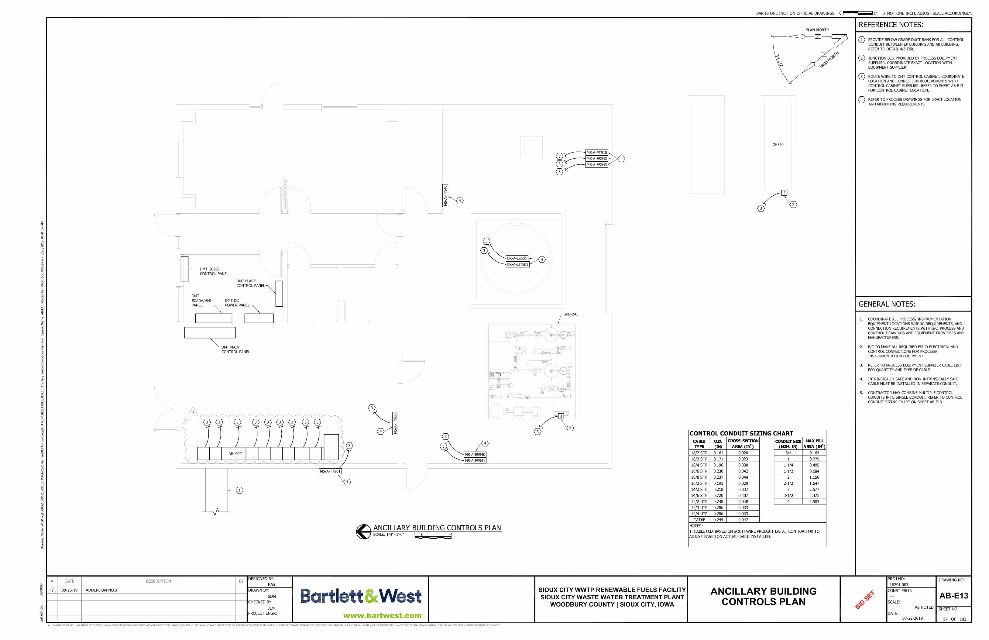
4. REMOVE AND REPLACE Sheet AB-E13 with the attached.
5. REMOVE AND REPLACE Sheet GP-P10 with the attached.
6. REMOVE AND REPLACE Sheet GP-P11 with the attached.
7. REMOVE AND REPLACE Sheet Z-E30 with the attached.
8. REMOVE AND REPLACE Sheet Z-E60 with the attached. QUESTIONS
1. None ATTACHMENTS
1. Bartlett & West Submittal Cover Sheet and Bill of Materials & Drawing Portion of MCC Submittal from DMT
2. General Sheet G-E10 3. Civil Sheet RF-C15 4. Ancillary Building Sheets AB-E12 and AB-E13 5. Gas Processing Building Sheets GP-P10 and GP-P11 6. Details Sheets Z-E30 and Z-E60

Addendum No.3
Page 3 of 3
All bidders shall acknowledge receipt and acceptance of this addendum by entering the addendum number on the appropriate space of the submitted Bid Form.
I hereby certify that this engineering document was prepared by me or under my direct personal supervision and that I am a duly licensed Professional Engineer under the laws of the State of Iowa.
Date: 08/26/19
JEREMEY T. LAY, PE
License No.23872
My renewal date is 12/31/20
Pages or sheets covered by this seal:
Entire Document.

Submittal Transmittal
Page 1 of 1
To: [email protected] Date: 8/22/2019Project No.: 018291.003Project Name: Sioux City Biogas & HSW Design
From: Matt Freed Re: MCC Submittal
Type: SubmittalPurpose: Make Corrections Noted
SPEC SECTION: MCC - Bid V1
REMARKS: Move 3200A MCB to the far-left side of the MCC. Provide bottom cable entry in 3200A MCB Section. DG1 VFD, 16 FLA is not required. Provide 15A3P circuit breaker in
MCC for Dry Cooler.
ContentsQUANTITY: 1 DATED: 8/20/2019 NUMBER:
DESCRIPTION:MCC Submittal.pdf
ACTION:REMARKS:
COPIES:
Joe Honner (Bartlett & West)

Submittal for Approval
General Order
LPO0022534
Volume 1 of 1
Equipment:
Motor Control Centers
DMT Clear Gas MCC
Date: 8/20/2019
PO# PO19-00173
©2019 Eaton Corporation, All Rights Reserved

Main Table of Contents
Contact Page 3Comment Page 4
1.0 Motor Control Centers 51.1 Bill of Material 71.2 Drawings 101.3 Technical Documents 17

For new project opportunities, contact:
Sales Person
For logistical support, contact: For technical support, contact:
Contact Information
Scott Anderson26850 Sw Kinsman RdWilsonville, OR 97070Phone: 503-582-2712
Fax: [email protected]
Cody Reese175 Vista Boulevard 175 Vista Boulevard
Arden, NC 28704Phone: 828-651-0867
Fax: [email protected]
John Mckinney
Arden, NC 28704Phone: 828-651-0829
Fax: [email protected]
Project Coordinator Project Engineer

PROJECT COMMENTS Approved Approved as Noted Partial Approval Rejected Revise and Re-submit Release all for manufacture. Release all for manufacture. Release approved sections No release No re-submittal required. Make necessary changes for manufacture. Re-submit. Re-submit all. Show changes on const. drawings. Rejected sections
Lug Sizes for all equipment have been verified
Top or Bottom Entry for all equipment has been verified
Shipping splits have been verified
Nameplate information has been verified for all equipment
Orientation of breakers has been verified for all equipment Stamp or Signature Customer Comments: No Comments (check here)……………
LPO0022534
The following information is pertinent with the return of this submittal. Eatonrequires all information to be initialed and a final signature of responsible party.

Motor Control Centers

Motor Control CentersSection Table of Contents
1.0 Motor Control Centers 5Section Table of Contents 6
1.1 Bill of Material 71.1.1 Separate Bills of Material by Product (Detailed) 8
1.2 Drawings 101.2.1 Item 001 (Approval Drawings): FVC 11
1.3 Technical Documents 171.3.1 Freedom Starter & Contactor Tech Data 181.3.2 Freedom & Flashgard MCC General Description 261.3.3 IQ100 Series Meter Tech Data 391.3.4 Surge Protection Device Tech Data 441.3.5 F-Frame Breaker Tech Data 531.3.6 Transformer Tech Data 551.3.7 Transformer Cat Num System 601.3.8 PRL1A Panelboard Tech Data 621.3.9 HMCP Breaker Tech Data 65
1.3.10 S811+ Soft Starter Tech Data 771.3.11 K-Frame Breaker Tech Data 1021.3.12 CPX Drive Tech Data 1041.3.13 Magnum Breaker Tech Data 129

Bill of Material

Detail Bill of Material Page 1 of 2
Project Name: DMT Clear Gas MCC Negotiation No: POIU0808X9K1 General Order No: LPO0022534 Alternate No: R001
Item No. Qty Product Description 001 1 Motor Control Centers 60 Hz, Class 1B wiring, 480V 3-Phase Service, 65,000 Bracing,
Short Circuit Rating, Top Incoming, NEMA 1 Gasketed 21" Front Mt Only enclosure, 3200A Copper Main Horizontal Bus, No Neutral, Main Breaker. Used X-Space: 123, Blank X-Space: 9, Future X-Space: 0, MCC Lead Time Code: U.
Designation update_073119
Qty List of Materials 1 IQ150 METER/DISPLAY 60HZ 5A 90-265V AC/DC 1 MDS6, Draw-out 3200AF Main Bkr (3200A trip), Lugs: Bus-Duct-Transition 1 IQ150 2 600V Potential transformer 2 3200A Current transformer 1 3 Phase Voltage Monitor 1 IT Soft Start S811 Non-Communicating, 650 Amp, Standard Duty, [HMCP],
Bottom Cable Exit
1 DG1 VFD, Constant torque, 38 FLA, 480V, HMCP 1 DG1 VFD, Constant torque, 16 FLA, 480V, HMCP 7 DG1 VFD, Constant torque, 2.2 FLA, 480V, HMCP 1 CPX AFD, 140A, CT 1 DG1 VFD, Constant torque, 7.6 FLA, 480V, HMCP 3 DG1 VFD, Constant torque, 12 FLA, 480V, HMCP 1 HFD Bkr (225A trip) 1 HKD Bkr (400A trip) 2 HFDTwin Bkr (50A /50A trip) 1 HFDTwin Bkr (150A /150A trip) 15 Terminal Block - Latching Pull-Apart, Std. 15 #16awg, MTW Control Wire 15 Wiremarkers at Each End 1 Magnum DS RMS520LSI Trip 1 IT Soft Start 120V Interface & 100VA CPT 14 Keypad (Included) 1 6 DI, 1 DO, 2 AI, 1 AO, 1 +10 Vdc ref, 2 ext, +24 Vdc/EXT + 24 Vdc 1 2 RO (NC-NO) 1 CPX9000 Input Contactor (Included) 1 CPX9000 Inline Fuses (Included) 14 Output Reactor (Included) 1 25 Kva 1ph, 440-480V / 120-240V High Efficiency Xfmr, 125A Pri., 150A
Sec. Bkr.
1 PL1A Panelboard 100A 120/240V 1PH 3W 18 CKT 18 Pnlbd Bkr, BAB 1 Pole 20A bkr 1 200KA, SPD Standard Features Package, with Circuit Breaker 3 12" Door 1 18" Door 11 Tin Plated horizontal bus 11 Sleeve Wrapped Insulated main bus 11 Labyrinth, Isolated/Insulated vertical bus barrier with shutters 1 12" Top Hat 9 600A Vertical Bus (Tin-plated cu) 1 Enclosure End Braces, IBC/CBC Seismic Qualified 11 600A Horiz. Cu Gnd Bus, 1/4" x 2" Bar 11 65KA Bus Bracing 2 800A Vertical Bus (Tin-plated cu) 10 3200A Copper Frnt Mtd 21" NEMA 1 Gasketed 1 C-H Switchgear Transition, Main Bus

Detail Bill of Material Page 2 of 2
Project Name: DMT Clear Gas MCC Negotiation No: POIU0808X9K1 General Order No: LPO0022534 Alternate No: R001
Qty List of Materials 1 Copper windings on XFMR 1 Bus Duct Transition Structure 1
Eaton Selling Policy 25-000 applies.
All orders must be released for manufacture within 90 days of date of order entry. If approval drawings are required, drawings must be returned
approved for release within 60 days of mailing. If drawings are not returned accordingly, and/or if shipment is delayed for any reason, the price of the
order will increase by 1.0% per month or fraction thereof for the time the shipment is delayed.

Drawings

MCC General Information
MCC General InformationWiring Diagram Type Eaton StandardMCC QuantityStandards UL845, NEMA, NECSpecial Codes ULService Voltage (3 Phase) 480Frequency 60System 3PH3WWitness Testing No
Enclosure SpecificationsTotal Structures 11Type NEMA 1 GasketedDepth 21" Front Mt OnlyHeight 90"Horizontal Wireways 9" High, Top & BottomVertical Wireways 4"Channel Sills NoBottom Plates None150 Watt Space Heaters NoSpace Heater Thermostat NoMaster Terminal Block Location NoneIBC/CBC Seismic Qualified YesABS Certified No
Bus System SpecificationsMain Bus Amps 3200Main Bus Material CopperMain Bus Bar Plating TinInsulated Horiz. Bus Yes1000A/sq in. Cu Bus NoVertical Bus Amps See Structure ScheduleVertical Bus Material Tin Plated CopperVertical Bus Barrier Labyrinth, Isolated/
Insulated with shuttersBus Bracing 65,000Ground Bus 600Ground Bus Location TopGround Bus Lug Size 1-#6-350KcmilGround Bus Lug Type ScrewPlug-in 300A Vert. Gnd. Bus NoNeutral NoneHorizontal Bus Temperature Rise 65 deg CBottom Vert. Bus Barrier NoVertical Ground Bus No
Incoming Line TerminationDevice: MDS6, Draw-out 3200AF Main Bkr (3200A trip), Lugs: Bus-Duct-TransitionCable Entry TopSplice Kit / Transition NoneMCC Type Match UpMCC Type Match Up GO# ** None **
MCC Starter SpecificationsWiring Class 1BControl Voltage 120Control Voltage Src Ind CPTNameplate Size 1" X 2.5"Nameplate Color Black / White Letters
Pilot Dev. Model 10250TInd. Light Type 6v Xfmr
Structure ScheduleThere are 11 structure(s).Structure(s) 1, 10, 11, 2, 3, 4, 5, 6, 7 have a 600 A Vertical Bus.Structure(s) 8, 9 have a 800 A Vertical Bus.Total width of all sections is 232"Height of all sections is 90"
Unit Modifications#16awg, MTW Control WireTerminal Block - Latching Pull-Apart, Std.Wiremarkers at Each End
NEG-ALT Number
PREPARED BY DATE
APPROVED BY DATE
VERSION
REVISION DWG SIZE
JOB NAME
DESIGNATION
TYPE
G.O.
DRAWING TYPE
ITEM SHEET
The information on this document is created by Eaton Corporation. It is disclosed in confidence and it is only to be used for the purpose in which it is supplied.
POIU0808X9K1-R001
MOLLY HENDRYX 8/20/2019
1.0.2.3
A
Eaton Fayetteville, NCDMT Clear Gas MCCupdate_073119
Freedom+ MCC 2100
LPO0022534
Customer Appr.
001 1 of 6

Notes/Special Instructions
Copper windings on XFMRBus Duct Transition Structure 1
NEG-ALT Number
PREPARED BY DATE
APPROVED BY DATE
VERSION
REVISION DWG SIZE
JOB NAME
DESIGNATION
TYPE
G.O.
DRAWING TYPE
ITEM SHEET
The information on this document is created by Eaton Corporation. It is disclosed in confidence and it is only to be used for the purpose in which it is supplied.
POIU0808X9K1-R001
MOLLY HENDRYX 8/20/2019
1.0.2.3
A
Eaton Fayetteville, NCDMT Clear Gas MCCupdate_073119
Freedom+ MCC 2100
LPO0022534
Customer Appr.
001 2 of 6

A
B
C
D
E
F
G
H
J
K
L
M
20.156
1F
MTRPVM
SPD
HFD50/50
HFD50/50
HFD150/150
24.078
2F
25KVA
18CKT
20.078
3F
DG1
FR12.2A CT
DG1
FR12.2A CT
DG1
FR12.2A CT
DG1
FR12.2A CT
20.078
4F
DG1
FR12.2A CT
DG1
FR12.2A CT
DG1
FR12.2A CT
DG1
FR17.6A CT
20.078
5F
DG1
FR2
12A CT
DG1
FR2
12A CT
DG1
FR2
12A CT
20.078
6F
DG1FR338A CT
DG1
FR2
16A CT
40.078
7F
CPX DriveFR8
140A CT
16.621.0
20.156
11.25
1.25
Floor View
24.078
11.25
1.25
20.078
11.25
1.25
20.078
11.25
1.25
20.078
11.25
1.25
20.078
11.25
1.25
40.078
11.25
1.25
17.55.41
Top View
21.55.41
17.55.41
17.55.41
17.55.41
17.55.41
37.55.41
NEG-ALT Number
PREPARED BY DATE
APPROVED BY DATE
VERSION
REVISION DWG SIZE
JOB NAME
DESIGNATION
TYPE
G.O.
DRAWING TYPE
ITEM SHEET
The information on this document is created by Eaton Corporation. It is disclosed in confidence and it is only to be used for the purpose in which it is supplied.
POIU0808X9K1-R001
MOLLY HENDRYX 8/20/2019
1.0.2.3
A
Eaton Fayetteville, NCDMT Clear Gas MCCupdate_073119
Freedom+ MCC 2100
LPO0022534
Customer Appr.
001 3 of 6

20.078
8F
IT_650
20.078
9F
HFD3225
HKD3400
24.078
11F
MAG_DS
4.078
10F
Tran
sitio
n
20.078
11.25
1.25
20.078
11.25
1.25
24.078
11.25
1.25
17.55.41
17.55.41
21.55.41
NEG-ALT Number
PREPARED BY DATE
APPROVED BY DATE
VERSION
REVISION DWG SIZE
JOB NAME
DESIGNATION
TYPE
G.O.
DRAWING TYPE
ITEM SHEET
The information on this document is created by Eaton Corporation. It is disclosed in confidence and it is only to be used for the purpose in which it is supplied.
POIU0808X9K1-R001
MOLLY HENDRYX 8/20/2019
1.0.2.3
A
Eaton Fayetteville, NCDMT Clear Gas MCCupdate_073119
Freedom+ MCC 2100
LPO0022534
Customer Appr.
001 4 of 6

1B IQ150NONE
1C 3 Phase VoltageMonitor
1F 200KA, SPD StandardFeatures Package,with Circuit Breaker NONE
1HL HFDTwin Bkr (50A HFD/50A trip) 3P
5599A85.DWF 501HR HFDTwin Bkr (50A HFD
/50A trip) 3P5599A85.DWF 50
1KL HFDTwin Bkr (50A HFD/50A trip) 3P
5599A85.DWF 501KR HFDTwin Bkr (50A HFD
/50A trip) 3P5599A85.DWF 50
1ML HFDTwin Bkr (150A HFD/150A trip) 3P
5599A85.DWF 1501MR HFDTwin Bkr (150A HFD
/150A trip) 3P5599A85.DWF 150
2B 12" Door2F PL1A Panelboard 18 Pnlbd Bkr, BAB 1 Pole 20A bkr
100A 120/240V 1PH3W 18 CKT 5A10397.DWF
2M 25 Kva 1ph, 440-480V/ 120-240V HighEfficiency Xfmr, 125A Pri., 150A Sec. Bkr.
5A10397.DWF
3C DG1 VFD, Constant HMCP 1 Keypad (Included)torque, 2.2 FLA, 1/2.2 3P 1 Output Reactor (Included)480V, HMCP NONE 7
3F DG1 VFD, Constant HMCP 1 Keypad (Included)torque, 2.2 FLA, 1/2.2 3P 1 Output Reactor (Included)480V, HMCP NONE 7
3J DG1 VFD, Constant HMCP 1 Keypad (Included)torque, 2.2 FLA, 1/2.2 3P 1 Output Reactor (Included)480V, HMCP NONE 7
3M DG1 VFD, Constant HMCP 1 Keypad (Included)torque, 2.2 FLA, 1/2.2 3P 1 Output Reactor (Included)480V, HMCP NONE 7
4C DG1 VFD, Constant HMCP 1 Keypad (Included)torque, 2.2 FLA, 1/2.2 3P 1 Output Reactor (Included)480V, HMCP NONE 7
4F DG1 VFD, Constant HMCP 1 Keypad (Included)torque, 2.2 FLA, 1/2.2 3P 1 Output Reactor (Included)480V, HMCP NONE 7
4J DG1 VFD, Constant HMCP 1 Keypad (Included)torque, 2.2 FLA, 1/2.2 3P 1 Output Reactor (Included)480V, HMCP NONE 7
4M DG1 VFD, Constant HMCP 1 Keypad (Included)torque, 7.6 FLA, 5/7.6 3P 1 Output Reactor (Included)480V, HMCP NONE 15
5D DG1 VFD, Constant HMCP 1 Keypad (Included)torque, 12 FLA, 7.5/12 3P 1 Output Reactor (Included)
Unit Nameplate Description Class Starter SizeHP/FLAWire Diag.
Bkr/SwPolesTrip/Clip
UnitFeatures
NEG-ALT Number
PREPARED BY DATE
APPROVED BY DATE
VERSION
REVISION DWG SIZE
JOB NAME
DESIGNATION
TYPE
G.O.
DRAWING TYPE
ITEM SHEET
The information on this document is created by Eaton Corporation. It is disclosed in confidence and it is only to be used for the purpose in which it is supplied.
POIU0808X9K1-R001
MOLLY HENDRYX 8/20/2019
1.0.2.3
A
Eaton Fayetteville, NCDMT Clear Gas MCCupdate_073119
Freedom+ MCC 2100
LPO0022534
Customer Appr.
001 5 of 6

480V, HMCP NONE 305H DG1 VFD, Constant HMCP 1 Keypad (Included)
torque, 12 FLA, 7.5/12 3P 1 Output Reactor (Included)480V, HMCP NONE 30
5M DG1 VFD, Constant HMCP 1 Keypad (Included)torque, 12 FLA, 7.5/12 3P 1 Output Reactor (Included)480V, HMCP NONE 30
6B 12" Door6F DG1 VFD, Constant HMCP 1 Keypad (Included)
torque, 16 FLA, 10/16 3P 1 Output Reactor (Included)480V, HMCP NONE 30
6M DG1 VFD, Constant HMCP 1 Keypad (Included)torque, 38 FLA, 25/38 3P 1 Output Reactor (Included)480V, HMCP NONE 50
7M FB110 VFD CPX AFD, 140A, CT HMCP 1 Keypad (Included)/140 3P 1 6 DI, 1 DO, 2 AI, 1 AO, 1 +10 Vdc
ref, 2 ext, +24 Vdc/EXT + 24 Vdc285267.DWF 1 2 RO (NC-NO)
1 CPX9000 Input Contactor (Included)
1 CPX9000 Inline Fuses (Included)1 Output Reactor (Included)
8M IT Soft Start S811 IT06 650 HMCP 1 IT Soft Start 120V Interface & 100VA CPT
Non-Communicating, 450 3P650 Amp, Standard Duty, [HMCP], Bottom Cable Exit
NONE 1200
9C HFD Bkr (225A trip) HFD3P
5599A85.DWF 2259G HKD Bkr (400A trip) HKD
3P5599A85.DWF 400
9J 12" Door9M 18" Door10M Description not
availableNONE
11M MDS6, Draw-out MDS6 1 Magnum DS RMS520LSI Trip3200AF Main Bkr 3P(3200A trip), Lugs: Bus-Duct-Transition
NONE 3200
Unit Nameplate Description Class Starter SizeHP/FLAWire Diag.
Bkr/SwPolesTrip/Clip
UnitFeatures
NEG-ALT Number
PREPARED BY DATE
APPROVED BY DATE
VERSION
REVISION DWG SIZE
JOB NAME
DESIGNATION
TYPE
G.O.
DRAWING TYPE
ITEM SHEET
The information on this document is created by Eaton Corporation. It is disclosed in confidence and it is only to be used for the purpose in which it is supplied.
POIU0808X9K1-R001
MOLLY HENDRYX 8/20/2019
1.0.2.3
A
Eaton Fayetteville, NCDMT Clear Gas MCCupdate_073119
Freedom+ MCC 2100
LPO0022534
Customer Appr.
001 6 of 6


DRY / AMBEINT
GLYCOL COOLER
CHILLER
NO.1
U
.
S
.
G
.
S
.
C
I
T
Y
1
0
0
.
4
5
U
S
G
S
1
1
0
0
.
8
2
U
S
G
S
1
1
0
0
.
6
4
C
I
T
Y
=
1
0
0
.
3
8
0 60' 120'
SCALE: 1"=60'
YARD PIPING PLAN
ALL RIGHTS RESERVED. ALL BARTLETT & WEST PLANS, SPECIFICATIONS AND DRAWINGS ARE PROTECTED UNDER COPYRIGHT LAW, AND NO PART MAY BE COPIED, REPRODUCED, DISPLAYED PUBLICLY, USED TO CREATE DERIVATIVES, DISTRIBUTED, STORED IN A RETRIEVAL SYSTEM OR TRANSMITTED IN ANY FORM BY ANY MEANS WITHOUT PRIOR WRITTEN PERMISSION OF BARTLETT & WEST.
SHEET NO:
DATE:
CHECKED BY:
DRAWN BY:
PROJECT ENGR:
DATE# DESCRIPTION BY
PROJ NO:
DRAWING NO:
Draw
ing N
am
e: C:\pw
data\topeka01\jdm
00688\dm
s62509\18291.003C_YardPipingPlan.dw
g Layout N
am
e: RF-C15 O
VERALL PLAN
Plotted By: JD
M00688 Plotted on: 8/22/2019 3:05:06 PM
OF
www.bartwest.com
Last edit on: 8/22/2019 3:02 PM
by: JD
M00688
1"BAR IS ONE INCH ON OFFICIAL DRAWINGS. IF NOT ONE INCH, ADJUST SCALE ACCORDINGLY.0
18291.003
---
SCALE:
AS NOTED
07-22-2019
RF-C15
30 102
JDM
JDM
JTL
DESIGNED BY:
CONST PROJ:
RENEWABLE FUELS FACILITY
YARD PIPING PLAN
SIOUX CITY WWTP RENEWABLE FUELS FACILITY
SIOUX CITY WASTE WATER TREATMENT PLANT
WOODBURY COUNTY | SIOUX CITY, IOWA
B
I
D
S
E
T
OVERALL PLAN
FUTURE
WAREHOUSE
HIGH BTU FLARE
7
5
'
7
5
'
B
U
F
F
E
R
R
5
0
'
R
A
D
I
A
N
T
H
E
A
T
S
A
F
E
T
Y
R
A
D
I
U
S
FUTURE
ANCILLARY
BUILDINGS
FUTURE GAS
PROCESS
BUILDING
TAP EXISTING 20" WATERLINE WITH
10" TAPPING SLEEVE EXTEND 10"
WATERLINE
TAP EXISTING 8" WATERLINE AND
EXTEND 4" WATERLINE TO BUILDING
RF-C24
RF-C23
RF-C22
RF-C25
RF
-C
31
RF-C32
EXISTING FIRE HYDRANT
ANCILLARY
BUILDINGS
GAS PROCESS
BUILDING
SEE SHEET CT-D11
FOR CONTINUATION
OF TAIL GAS PIPING.
MID AMERICAN
INTERCONNECT
STATION
10"X 10" X 10" TEE EXTEND 8" TO GP
BUILDING & 4" TO AC BUILDING
FIBER OPTIC CONDUIT
TO ADMIN BUILDING
FIBER OPTIC CONDUIT
TO MID AMERICAN
BUILDING
1
108/26/19 ADDENDUM NO. 3 JDM
EXISTING
MANHOLE
EMH-F
EXISTING
MANHOLE
EMH-G
EXISTING
12, 470V
SWITCHGEAR