Embed Size (px)
Citation preview

AD 4 - 1 ITB-PW-U-12-14 – BEACHSIDE SEWER SERVICE – PHASE 1
ADDENDUM NO. 4
ITB-PW-U-12-14 Beachside Sewer Service – Phase 1 ISSUE DATE: July 20, 2012 BID DATE: July 24, 2012 @ 2:00 P.M. TO: All Prospective Bidders and Others Concerned SUBJECT: Addendum No. 4 to Bidding Requirements and Contract Documents for BEACHSIDE SEWER SERVICE −−−− PHASE 1 PALM COAST, FLORIDA INTENT: This Addendum is issued prior to the date bids are due in order to incorporate the
following clarifications, additions, omissions, deletions, or changes to the Contract Documents.
Except as hereinafter specified, the work shall be in accordance with the Drawings and
Specifications. Bidders are to use the changed quantities of the items listed on this Addendum in their
proposals, and it shall become a part of the Contract Documents when construction is executed.
Bidders are reminded that this Addendum must be noted on the fifth page of the “Official City Bid Form” when they submit their proposal. A signed copy of the Addendum must also be included with your bid submittal. The Bidding Requirements and Contract Documents for the subject project are hereby amended as follows: 1. STATEMENTS
a. For the directional drills along S.R. A1A, the boring machine shall be located a minimum
of 8 feet from edge of pavement.
b. The size of the back ream on the directional drills along S.R. A1A has been reduced to 16”.
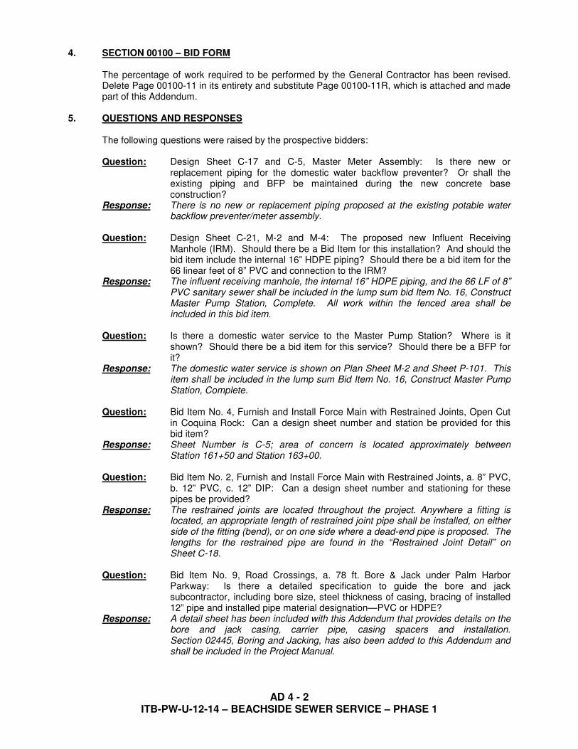
2. TABLE OF CONTENTS
a. Section 02445 has been added to the Table of Contents. Delete Page ii in its entirety and substitute Page iiR, which is attached and made part of this Addendum.
3. SECTION 02445 – BORING AND JACKING
a. Add this new Section to the Project Manual, a copy of which is attached and made part of this Addendum.
AD 4 - 2 ITB-PW-U-12-14 – BEACHSIDE SEWER SERVICE – PHASE 1
4. SECTION 00100 – BID FORM
The percentage of work required to be performed by the General Contractor has been revised. Delete Page 00100-11 in its entirety and substitute Page 00100-11R, which is attached and made part of this Addendum.
5. QUESTIONS AND RESPONSES
The following questions were raised by the prospective bidders: Question: Design Sheet C-17 and C-5, Master Meter Assembly: Is there new or
replacement piping for the domestic water backflow preventer? Or shall the existing piping and BFP be maintained during the new concrete base construction?
Response: There is no new or replacement piping proposed at the existing potable water backflow preventer/meter assembly.
Question: Design Sheet C-21, M-2 and M-4: The proposed new Influent Receiving
Manhole (IRM). Should there be a Bid Item for this installation? And should the bid item include the internal 16” HDPE piping? Should there be a bid item for the 66 linear feet of 8” PVC and connection to the IRM?
Response: The influent receiving manhole, the internal 16” HDPE piping, and the 66 LF of 8” PVC sanitary sewer shall be included in the lump sum bid Item No. 16, Construct Master Pump Station, Complete. All work within the fenced area shall be included in this bid item.
Question: Is there a domestic water service to the Master Pump Station? Where is it
shown? Should there be a bid item for this service? Should there be a BFP for it?
Response: The domestic water service is shown on Plan Sheet M-2 and Sheet P-101. This item shall be included in the lump sum Bid Item No. 16, Construct Master Pump Station, Complete.
Question: Bid Item No. 4, Furnish and Install Force Main with Restrained Joints, Open Cut
in Coquina Rock: Can a design sheet number and station be provided for this bid item?
Response: Sheet Number is C-5; area of concern is located approximately between Station 161+50 and Station 163+00.
Question: Bid Item No. 2, Furnish and Install Force Main with Restrained Joints, a. 8” PVC,
b. 12” PVC, c. 12” DIP: Can a design sheet number and stationing for these pipes be provided?
Response: The restrained joints are located throughout the project. Anywhere a fitting is located, an appropriate length of restrained joint pipe shall be installed, on either side of the fitting (bend), or on one side where a dead-end pipe is proposed. The lengths for the restrained pipe are found in the “Restrained Joint Detail” on Sheet C-18.
Question: Bid Item No. 9, Road Crossings, a. 78 ft. Bore & Jack under Palm Harbor
Parkway: Is there a detailed specification to guide the bore and jack subcontractor, including bore size, steel thickness of casing, bracing of installed 12” pipe and installed pipe material designation—PVC or HDPE?
Response: A detail sheet has been included with this Addendum that provides details on the bore and jack casing, carrier pipe, casing spacers and installation. Section 02445, Boring and Jacking, has also been added to this Addendum and shall be included in the Project Manual.

AD 4 - 3 ITB-PW-U-12-14 – BEACHSIDE SEWER SERVICE – PHASE 1
Question: Our insurance carrier needs to know the flood zone and how close the project site is to navigational water to adequately price your insurance requirements. Can you supply this information?
Response: The property resides in Flood Zone “X”. The distance from the project to the Intracoastal Waterway is approximately 850 feet.
Question: Can we use fusible PVC in lieu of HDPE? Response: No. HDPE is the only material for directional drilling. Question: What items, if any, will be direct purchase? Response: The direct purchase items are listed on Page 00100-17 of the Bid Section of the
Project Manual. Question: Will construction water be furnished to the contractor at no charge? Response: Construction water will be available from an existing hydrant located on the west
side of S.R. A1A. There will be no charge to the Contractor for water use. Question: Where will the construction access points be for the area along St. Joe Canal? Response: The access points will be from Colbert Lane and Club House Drive. Question: Can a detail or casing size for the proposed bore and jack be provided? Response: A detail sheet has been included with this Addendum that provides details on the
bore and jack casing, carrier pipe, casing spacers and installation. Section 02445, Boring and Jacking, has also been added to this Addendum and shall be included in the Project Manual.
Question: Where is the “flushing connection” as detailed on Plan Sheet C-19 to be used? Response: The location is shown on a revised Sheet C-10, which is included as part of this
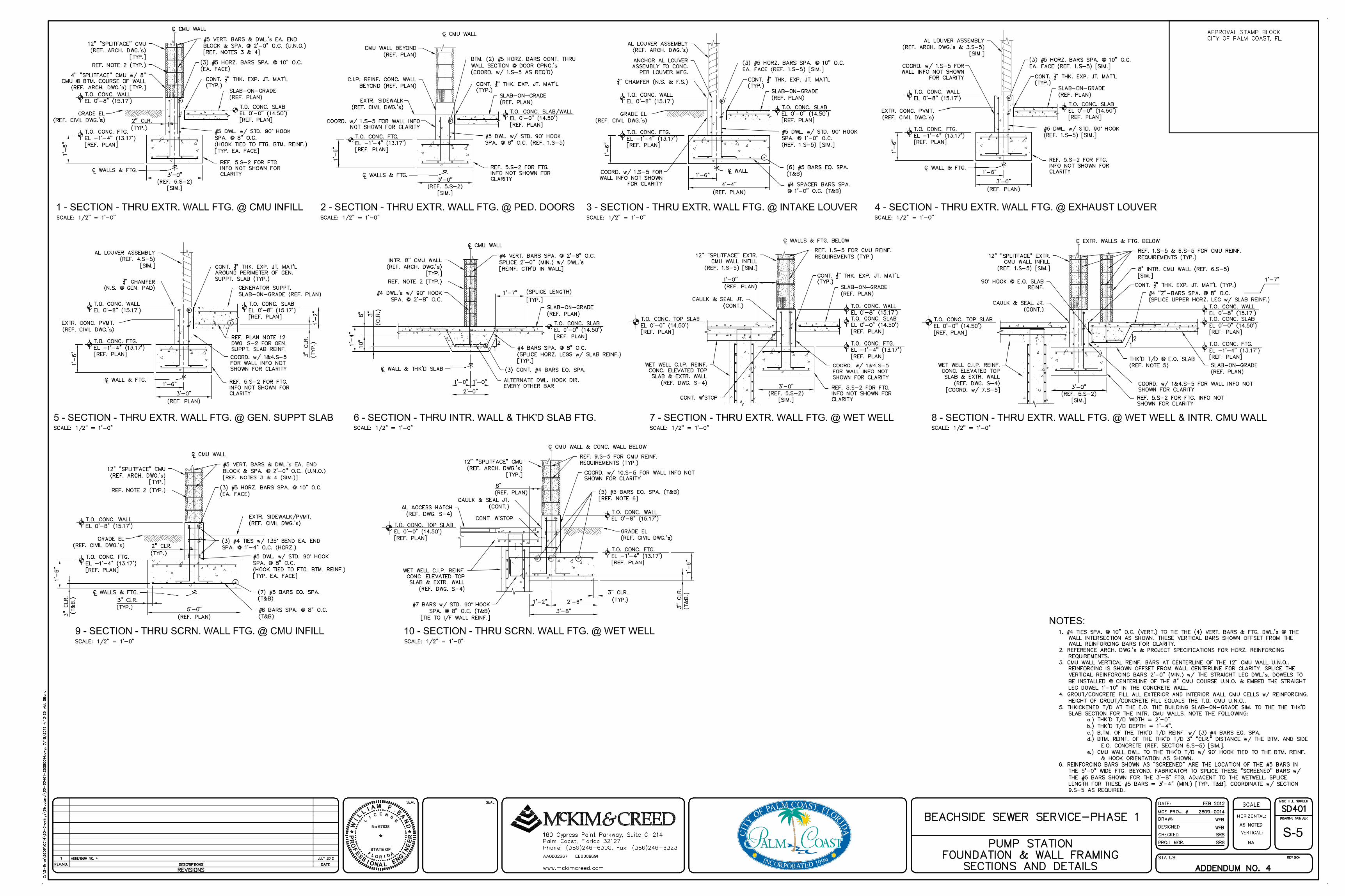
Addendum. Question: Plan Sheet S-4 shows the wet well base extended to 24’-0”. However, this
extension is not indicated on Plan Sheets M-3 and A301. Is this extended base slab required?
Response: The wet well base extension has been removed, and the revised design has been shown on the revised Sheet S-4, which was included in Addendum No. 3.
Question: Please confirm that the wall thickness for the wet well as shown on Plan Sheet
S-4 is 1’-6”. If you scale the wall thickness on “3” – Section”, it is 1’-2” thick. Response: The correct thickness for the wetwell wall is 1’-6”. Please refer to the revised
Sheet S-4 which was issued as part of Addendum No. 3. Question: Can a detail be provided for the 10” FRP screen and 8” SCH 80 PVC that is
shown on Plan Sheet M-2? Response: In lieu of 10” FRP screen, the detail should state “10” FRP duct and exhaust
flange, with a 3/4” #16 316 SS standard expanded metal screen 85% F.A.”. Question: What funding is available for the project? Will it be awarded if it is over the
budget of $2.5m? Response: Monies to fund the project will be withdrawn from an existing bond fund. The City
will consider award if the low bid exceeds the budget cost. Question: We would request an additional few days for bid due to the size of the latest
addendum. Please reconsider the due date. Response: Engineer and the City of Palm Coast have received one request for a time
extension from a Contractor. Therefore, the bid date will remain at July 24, 2012.

AD 4 - 4 ITB-PW-U-12-14 – BEACHSIDE SEWER SERVICE – PHASE 1
Question: What item is the landscaping to be put in? Response: Landscaping is to be included in Bid Item No. 16, Construct Master Pump
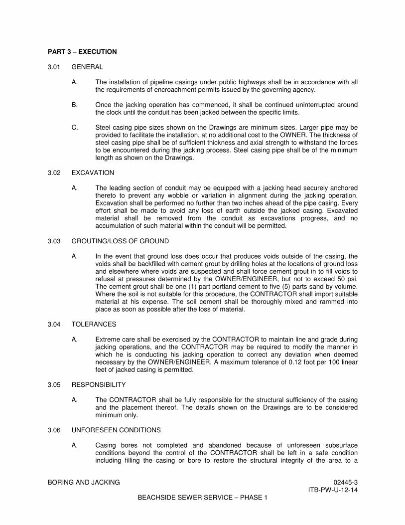
Station, Complete. 6. DETAIL SHEET
a. A Bore & Jack Detail Sheet is attached and made part of this Addendum.
7. DRAWINGS
b. Delete Sheet Nos. C-10 and C-19 in their entirety and substitute the revised sheets which are attached and made part of this Addendum.
DRAWING NO. DESCRIPTION
C-10
Revised fitting callout. Moved force main to the west. Added “Construct Flushing Connection” callout.
C-19 Revised the buried piping configuration in the “Flushing Connection Detail”.
S-5 New Sheet. S-6 New Sheet.
The foregoing changes are hereby incorporated into the Bidding Requirements and Contract Documents for BEACHSIDE SEWER SERVICE – PHASE 1, Palm Coast, Florida. Bids will be opened as previously announced.
THE CITY OF PALM COAST FLAGLER COUNTY, FLORIDA
By /s/ Jim Landon City Manager ATTACHMENTS: Table of Contents: Revised Page iiR Section 02445 – Boring and Jacking: Pages 02445-1 thru 02245-4 Section 00100 – Bid Form: Revised Page 00100-11R Detail Sheet: Bore & Jack Detail Drawings: Revised Sheets C-10 and C-19 Drawings: New Sheets S-5 and S-6 Acknowledgement: ____________________________________ Signature and Date _____________________________________ Printed Name and Title _____________________________________ Company Name
END OF ADDENDUM NO. 4
iiR
DIVISION 1 – GENERAL REQUIREMENTS PAGE
Technical Specifications ..........................................................................01000-1 Summary of Work....................................................................................01010-1 to 3 Measurement and Payment ......................................................................01025-1 to 10 Application for Payment ..........................................................................01027-1 to 3 Field Engineering .....................................................................................01050-1 to 2 Permits and Fees ......................................................................................01065-1 Codes, References and Abbreviations .....................................................01070-1 to 3 Special Project Procedures .......................................................................01100-1 to 2 Administrative Requirements ..................................................................01310-1 to 5 Color Video – Audio Pre-Construction Record .......................................01390-1 to 3 Quality Control .......................................................................................01400-1 to 3 Temporary Facilities and Controls...........................................................01500-1 to 5 Erosion and Sedimentation Control .........................................................01568-1 to 6 Traffic Regulation ....................................................................................01570-1 to 2 Material and Equipment ...........................................................................01600-1 to 4 Product Selection and Substitution Procedures .......................................01640-1 to 2 Start-Up ....................................................................................................01650-1 to 2 Systems Testing, Adjusting, and Balancing ............................................01660-1 to 3 Contract Closeout.....................................................................................01700-1 to 3 Project Record Documents ......................................................................01720-1 to 4 Operation and Maintenance Data.............................................................01730-1 to 6 Warranties and Bonds ..............................................................................01740-1 to 3 DIVISION 2 – SITE WORK PAGE INITIALS Fire Hydrant Assemblies..........................................................................02085-1 to 3 SRS Subsurface Investigation ..........................................................................02210-1 SRS Clearing, Grubbing and Stripping ............................................................02230-1 to 2 SRS Dewatering (During Construction) ..........................................................02240-1 to 3 SRS Soil Treatment ..........................................................................................02281-1 to 3 SRS Earthwork .................................................................................................02300-1 to 3 SRS Site Grading .............................................................................................02310-1 to 3 SRS Excavating, Backfilling and Compacting ................................................02315-1 to 8 SRS Boring and Jacking ..................................................................................02445-1 to 4 SRS Directional Drilling ..................................................................................02446-1 to 4 SRS Pavement Removal and Replacement ......................................................02700-1 to 7 SRS Chain Link Fence .....................................................................................02820-1 to 4 SRS Seeding .....................................................................................................02936-1 to 4 SRS Sodding ....................................................................................................02938-1 to 4 SRS DIVISION 3 – CONCRETE
Cast-In-Place Concrete ............................................................................03300-1 to 17 WFB Precast Concrete Structures .....................................................................03450-1 to 6 SRS Grout ........................................................................................................03600-1 to 2 WFB Leakage Testing of Hydraulic Structures ................................................03800-1 to 4 WFB

BORING AND JACKING 02445-1 ITB-PW-U-12-14
BEACHSIDE SEWER SERVICE – PHASE 1
SECTION 02445
BORING AND JACKING PART 1 – GENERAL 1.01 DESCRIPTION
A. Scope of Work: The work of this Section includes all labor, machinery, material, construction equipment and appliances required to perform in a good workmanlike manner all jacking of the pipeline casings.
B. Work Included in this Section:
1. Boring and jacking of a steel casing at designated locations. 2. Installations of carrier pipe within casing.
C. Related work Described Elsewhere:
1. Earthwork: Section 02300. 2. Excavating, Backfilling and Compacting: Section 02315.
1.02 SUBMITTALS
A. Submit certificates of inspection from the pipe manufacturer certifying that steel casing pipe supplied meets the requirements of these specifications.
B. Submit shop drawings of each steel casing, carrier pipe, casing insulators and end seals
prior to fabrication of piping, casing and appurtenances. C. Before starting excavation, the CONTRACTOR shall submit Drawings of jacking pit
bracing, casing (or conduit), and jacking head proposed to be used. In addition to submitting details for the jacking pit bracing, casing and jacking head, the CONTRACTOR shall submit to the OWNER/ENGINEER for review and record purposes, two copies of the Drawings, design details and calculations for support blocks, bracing to prevent pipe shifting or flotation and pressure cement mortar mix design, placement method and equipment.
D. If welding of casing pipe is required, submit welder’s certificate.
1.03 REQUIREMENTS
A. Unless otherwise specified, the methods and equipment used in jacking casing or conduit shall be optional with the CONTRACTOR, provided that the proposed method is approved by the OWNER. Such approval, however, shall in no way relieve the CONTRACTOR of the responsibility for making a satisfactory installation meeting the criteria set forth herein. Only workmen experienced in jacking operations shall be used in performing the work.

BORING AND JACKING 02445-2 ITB-PW-U-12-14
BEACHSIDE SEWER SERVICE – PHASE 1
B. Only a welder certified in the State of Florida shall perform welding operations on the casing pipe. Proof of such welding certificate shall be submitted prior to any boring and jacking operations.
PART 2 – PRODUCTS 2.01 STEEL CASING PIPE
A. Steel casing shall be new and unused Grade B steel pipe, minimum yield strength 35,000 psi, conforming to American Railway Engineering and Maintenance-of-Way Association (A.R.E.M.A.) Specifications for Pipeline Crossings Under Railway Tracks for Non-Flammable Substances - 1997, with allowance for corrosion; and shall conform to ASTM A 53 or AWWA C 202, latest editions, for mill pipe and ASTM A 139 or AWWA C 201, latest editions, for fabricated pipe. Thickness shall be as shown. Joints shall be electrifusion (arc) welded by operators qualified in accordance with American Welding Society Standard Procedure.
1. Steel Casing Pipe (wall thickness)
Railroad
O.D. FDOT Coated Not Coated 12” 0.250” 0.188” 0.188” 14” 0.250” 0.188” 0.250” 16” 0.250” 0.219” 0.281” 18” 0.250” 0.250” 0.312” 24” 0.250” 0.312” 0.375” 30” 0.312” 0.406” 0.469” 36” 0.375” 0.469” 0.531” 42” 0.500” 0.562” 0.625” 48” 0.500” 0.625” 0.688”
2.02 CARRIER PIPE
A. Carrier pipes shall be ductile iron and conform to ANSI A21.50 and ANSI A21.51. Restrained joints shall be used for the carrier pipe contained within casing pipes.
2.03 JOINTS
A. Field and shop welds of the casing pipes shall conform with the American Welding Society (AWS) standard specifications. The joints of sections of casing pipe to be jacked shall be welded with complete penetration, single-bevel groove type joints. The sections of steel casing shall be field welded in accordance with the applicable portions of AWWA C206 and AWS D7.0 for field welded pipe joints. Welds shall be airtight and continuous over the entire circumference of the pipe and shall not increase the outside pipe diameter by more than 3/4-inch. Contractor shall wire brush the welded joints and paint with Inertol Quick-Drying Primer 626 by Koppers Company or approved equal. It shall be the CONTRACTOR’S responsibility to provide stress transfer across the joints which is capable of resisting the jacking forces involved.
2.04 BRACING
A. The carrier pipe shall be braced to prevent shifting or flotation. The details of bracing and blocking of the pipe are shown on the Drawing detail sheets and are subject to the approval of the OWNER.
BORING AND JACKING 02445-3 ITB-PW-U-12-14
BEACHSIDE SEWER SERVICE – PHASE 1
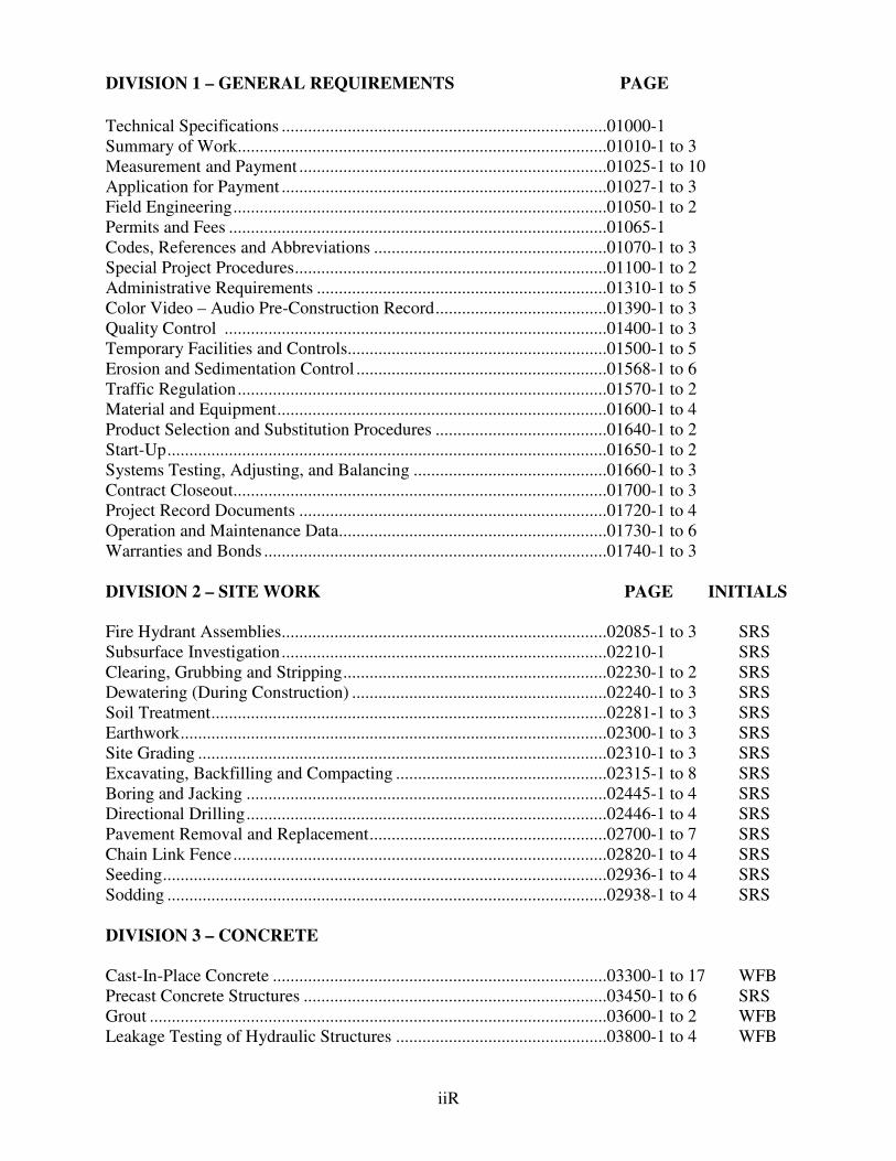
PART 3 – EXECUTION 3.01 GENERAL
A. The installation of pipeline casings under public highways shall be in accordance with all the requirements of encroachment permits issued by the governing agency.
B. Once the jacking operation has commenced, it shall be continued uninterrupted around
the clock until the conduit has been jacked between the specific limits. C. Steel casing pipe sizes shown on the Drawings are minimum sizes. Larger pipe may be
provided to facilitate the installation, at no additional cost to the OWNER. The thickness of steel casing pipe shall be of sufficient thickness and axial strength to withstand the forces to be encountered during the jacking process. Steel casing pipe shall be of the minimum length as shown on the Drawings.
3.02 EXCAVATION
A. The leading section of conduit may be equipped with a jacking head securely anchored thereto to prevent any wobble or variation in alignment during the jacking operation. Excavation shall be performed no further than two inches ahead of the pipe casing. Every effort shall be made to avoid any loss of earth outside the jacked casing. Excavated material shall be removed from the conduit as excavations progress, and no accumulation of such material within the conduit will be permitted.
3.03 GROUTING/LOSS OF GROUND
A. In the event that ground loss does occur that produces voids outside of the casing, the voids shall be backfilled with cement grout by drilling holes at the locations of ground loss and elsewhere where voids are suspected and shall force cement grout in to fill voids to refusal at pressures determined by the OWNER/ENGINEER, but not to exceed 50 psi. The cement grout shall be one (1) part portland cement to five (5) parts sand by volume. Where the soil is not suitable for this procedure, the CONTRACTOR shall import suitable material at his expense. The soil cement shall be thoroughly mixed and rammed into place as soon as possible after the loss of material.
3.04 TOLERANCES
A. Extreme care shall be exercised by the CONTRACTOR to maintain line and grade during jacking operations, and the CONTRACTOR may be required to modify the manner in which he is conducting his jacking operation to correct any deviation when deemed necessary by the OWNER/ENGINEER. A maximum tolerance of 0.12 foot per 100 linear feet of jacked casing is permitted.
3.05 RESPONSIBILITY
A. The CONTRACTOR shall be fully responsible for the structural sufficiency of the casing and the placement thereof. The details shown on the Drawings are to be considered minimum only.
3.06 UNFORESEEN CONDITIONS
A. Casing bores not completed and abandoned because of unforeseen subsurface conditions beyond the control of the CONTRACTOR shall be left in a safe condition including filling the casing or bore to restore the structural integrity of the area to a

BORING AND JACKING 02445-4 ITB-PW-U-12-14
BEACHSIDE SEWER SERVICE – PHASE 1
condition equal to that prior to construction. Casing or bore shall be filled completely with cement grout previously specified.
3.07 INSTALLATION OF CARRIER PIPE
A. Carrier pipe shall be installed within steel casing pipe as shown on the Drawings and specified hereinafter. The load of the carrier pipe shall be distributed along the casing by casing spacers.
B. Adjust the pipe grade, as required, by changing the casing spacers, and to maintain
carrier pipe lines, grades, and dimensions, as shown on the Drawings. C. If the alignment of the casing is such that the carrier pipe grade cannot be met, the grade
of the casing shall, if required by the OWNER/ENGINEER, be adjusted. If realignment is not deemed feasible by the OWNER/ENGINEER, another casing meeting the required grade shall be installed. The abandoned casing shall be filled with grout. Realignment or replacement work shall in no way result in extra cost to the OWNER.
D. Upon completion of the installation of the carrier pipe, each end of the steel casing shall
be sealed with a non-shrinking grout equal to Embeco 167 manufactured by Master Builders, or approved equal, as shown on the Drawings.
END OF SECTION
BID FORM 00100-11R ITB-PW-U-12-14
BEACHSIDE SEWER SERVICE – PHASE 1
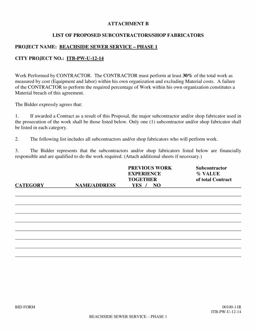
ATTACHMENT B
LIST OF PROPOSED SUBCONTRACTORS/SHOP FABRICATORS
PROJECT NAME: BEACHSIDE SEWER SERVICE – PHASE 1 CITY PROJECT NO.: ITB-PW-U-12-14 Work Performed by CONTRACTOR. The CONTRACTOR must perform at least 30% of the total work as measured by cost (Equipment and labor) within his own organization and excluding Material costs. A failure of the CONTRACTOR to perform the required percentage of Work within his own organization constitutes a Material breach of this agreement. The Bidder expressly agrees that: 1. If awarded a Contract as a result of this Proposal, the major subcontractor and/or shop fabricator used in the prosecution of the work shall be those listed below. Only one (1) subcontractor and/or shop fabricator shall be listed in each category. 2. The following list includes all subcontractors and/or shop fabricators who will perform work. 3. The Bidder represents that the subcontractors and/or shop fabricators listed below are financially responsible and are qualified to do the work required. (Attach additional sheets if necessary.)
PREVIOUS WORK Subcontractor EXPERIENCE % VALUE TOGETHER of total Contract
CATEGORY NAME/ADDRESS YES / NO

BEACHSIDE SEWER SERVICE-PHASE 1
BORE & JACK DETAIL

MAT
CH
LIN
E S
T A. 4
23+0
0S
EE
SH
EE
T C
-9 F
OR
CO
NTI
NU
ATIO
N
MATCH LINE STA. 429+00
MAT
CH
LIN
E S
TA. 4
29+0
0
MAT
CH
LIN
E S
TA. 4
36+0
0S
EE S
HE
ET C
-11
FOR
CO
NTI
NU
ATI
ON
PR
OFESS I ONA L E NG
I NE
ER
SCO
T T R . SPOONERL
I C E N S
E
No 23273
STATE OFF L O R I D A
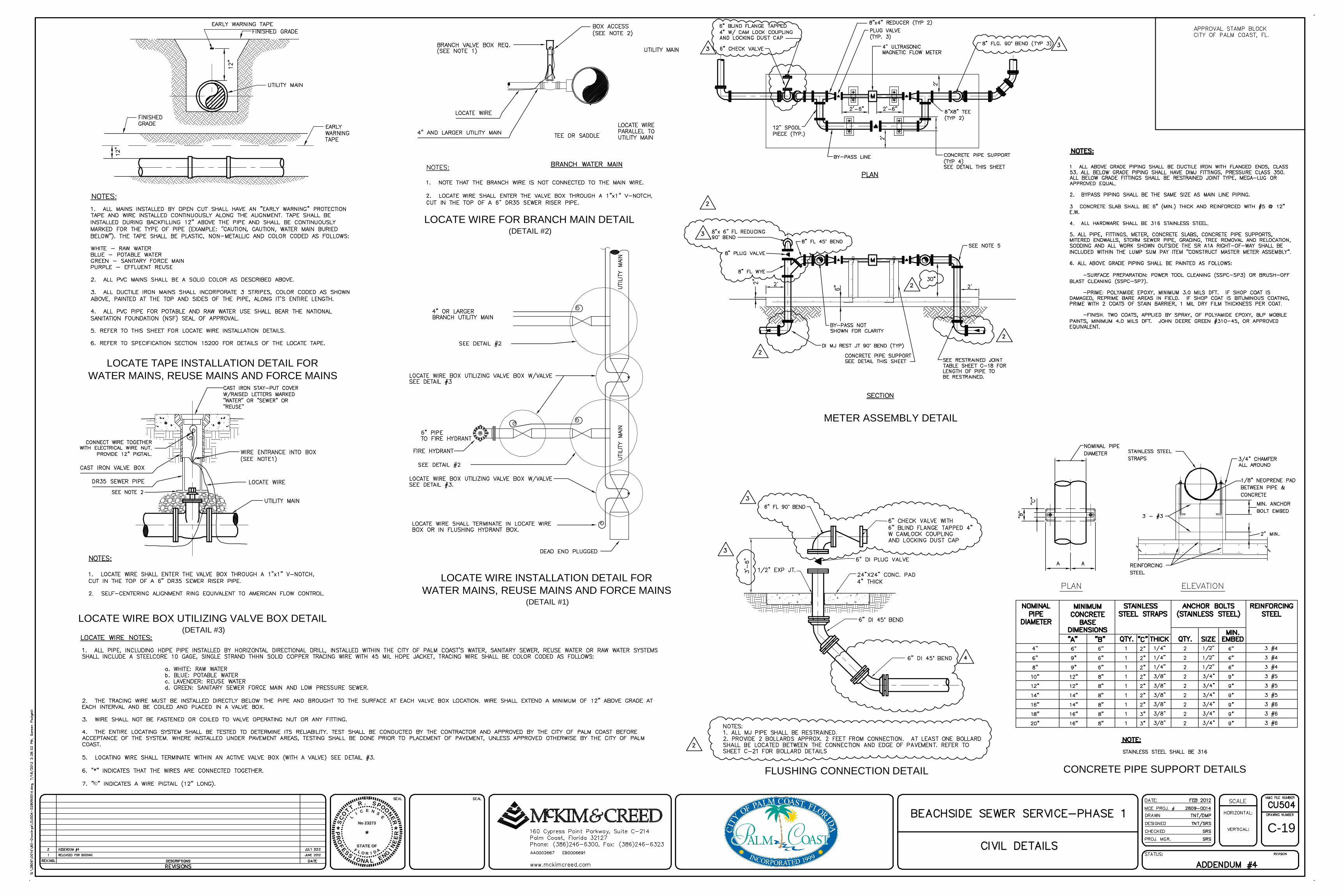
LOCATE TAPE INSTALLATION DETAIL FORWATER MAINS, REUSE MAINS AND FORCE MAINS
LOCATE WIRE INSTALLATION DETAIL FORWATER MAINS, REUSE MAINS AND FORCE MAINS
(DETAIL #1)
LOCATE WIRE FOR BRANCH MAIN DETAIL(DETAIL #2)
LOCATE WIRE BOX UTILIZING VALVE BOX DETAIL(DETAIL #3)
PR
OFESS I ONA L ENG
I NE
ER
SCO
T T R . SPOONERL
I C E N S
E
No 23273
STATE OFF L O R I D A
C-19
METER ASSEMBLY DETAIL
CONCRETE PIPE SUPPORT DETAILSFLUSHING CONNECTION DETAIL