Embed Size (px)
Citation preview

Adding a DRO to a Rong Fu Mill/Drill
By
Norm Berls

Why a DRO?
• Trying to achieve a precision of 0.001 inches.
• Experience has shown that my Rong Fu Mill/Drill is potentially capable of 0.001 inch precision.
• DRO is cheaper than a new mill and a CNC system.
• DRO is faster and easier to use than a micrometer.
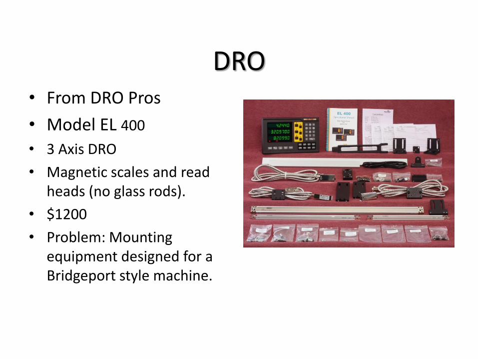
DRO • From DRO Pros
• Model EL 400
• 3 Axis DRO
• Magnetic scales and read heads (no glass rods).
• $1200
• Problem: Mounting equipment designed for a Bridgeport style machine.
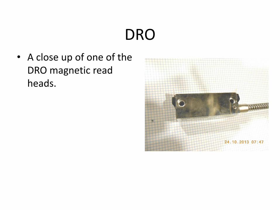
DRO • A close up of one of the
DRO magnetic read heads.
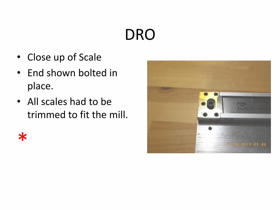
DRO • Close up of Scale
• End shown bolted in place.
• All scales had to be trimmed to fit the mill.
*
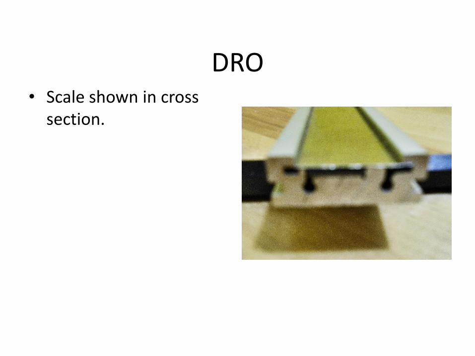
DRO • Scale shown in cross
section.

The Rong Fu Mill/Drill
• The Rong Fu Mill/Drill does not have the same large wide open areas for mounting a DRO that a Bridgeport style mill has.
• The EL 400 mounting brackets will not fit and cannot be used on a Rong Fu mill/drill.
• This creates an engineering opportunity.
Design of new mountings
• 2 man-months spent measuring and designing a series of new mounts.
• Detailed drawings were made. • Materials
– 1018 cold rolled steel – 6061 and 7075 aluminum – 360 brass – Stainless steel bolts (mostly)
• Imperial system threads selected for general purposes . • Some metric screws kept from EL 400 mounts to avoid modifying
scale bars and read heads. This would have invalidated the warranty. *
*
Design continued
• New design heavily over-engineered.
• Extra set screws added to facilitate adjustment of read heads vis-à-vis the magnetic scales.
• Attempt made to keep iron or steel surfaces from contacting magnetic scales.
• Everything put together with socket head cap screws, button head cap screws and set screws. No welding.
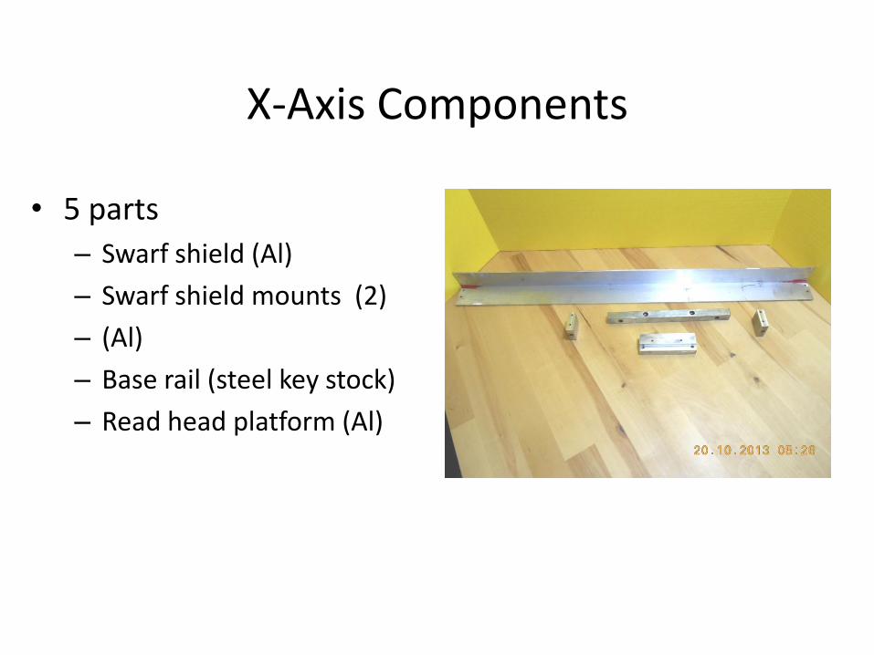
X-Axis Components
• 5 parts
– Swarf shield (Al)
– Swarf shield mounts (2)
– (Al)
– Base rail (steel key stock)
– Read head platform (Al)
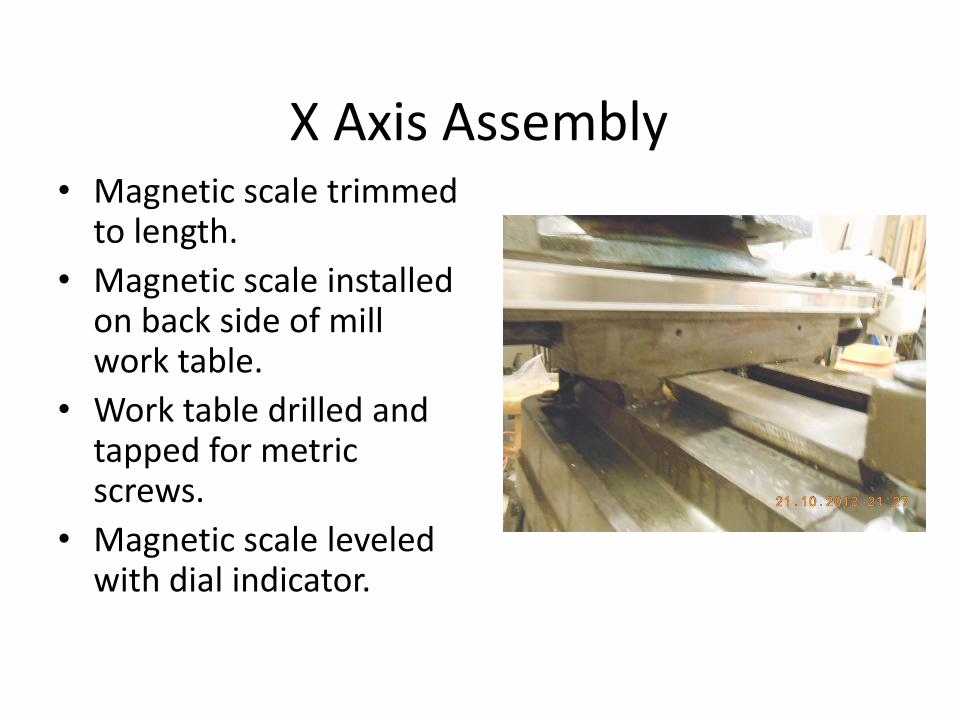
X Axis Assembly • Magnetic scale trimmed
to length.
• Magnetic scale installed on back side of mill work table.
• Work table drilled and tapped for metric screws.
• Magnetic scale leveled with dial indicator.
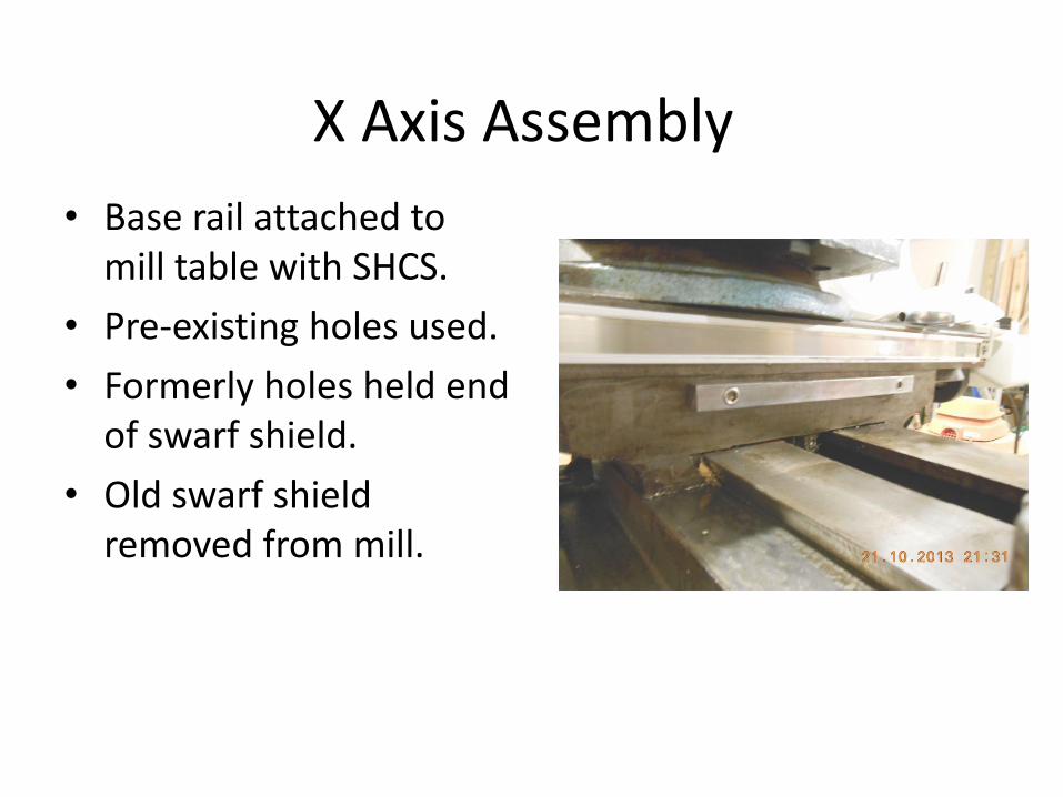
X Axis Assembly
• Base rail attached to mill table with SHCS.
• Pre-existing holes used.
• Formerly holes held end of swarf shield.
• Old swarf shield removed from mill.
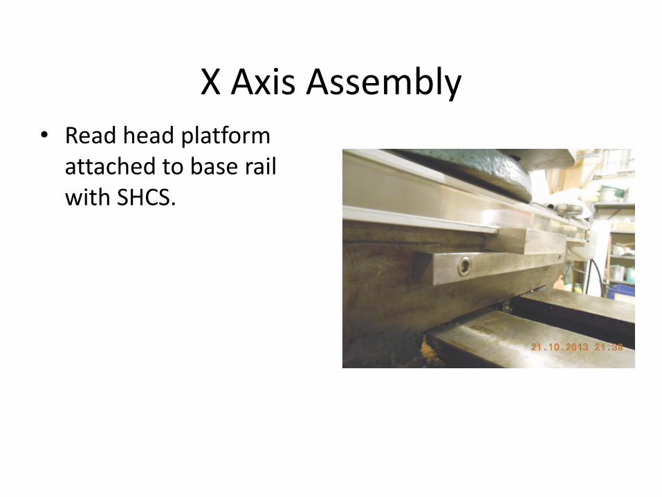
X Axis Assembly • Read head platform
attached to base rail with SHCS.
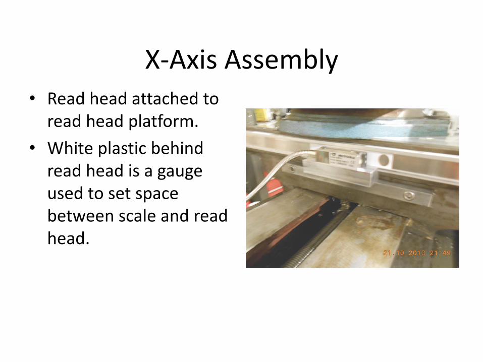
X-Axis Assembly • Read head attached to
read head platform.
• White plastic behind read head is a gauge used to set space between scale and read head.
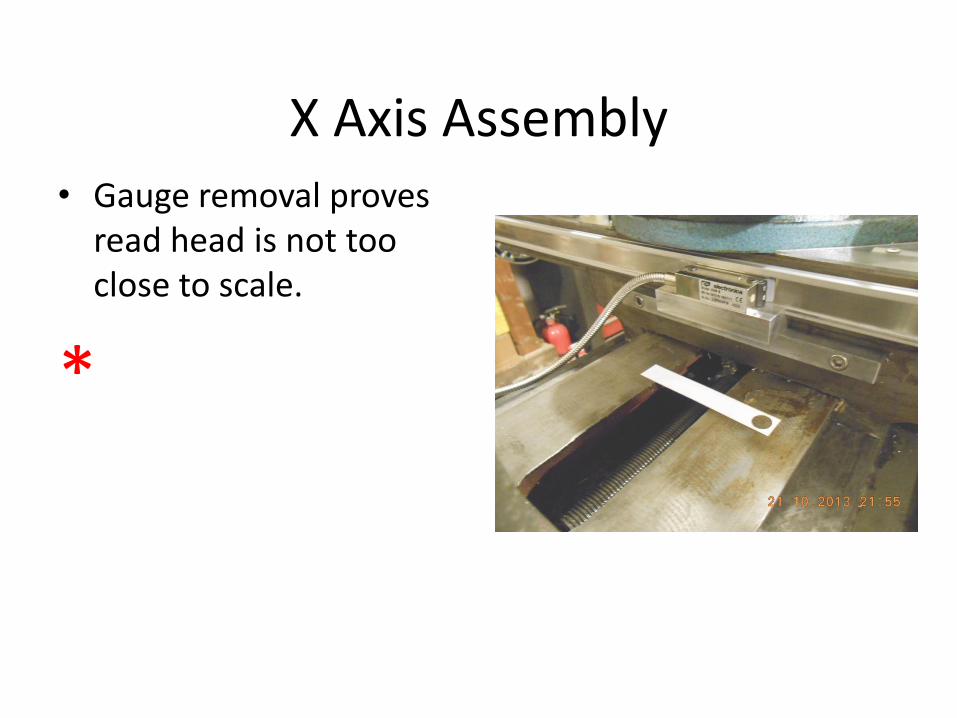
X Axis Assembly • Gauge removal proves
read head is not too close to scale.
*
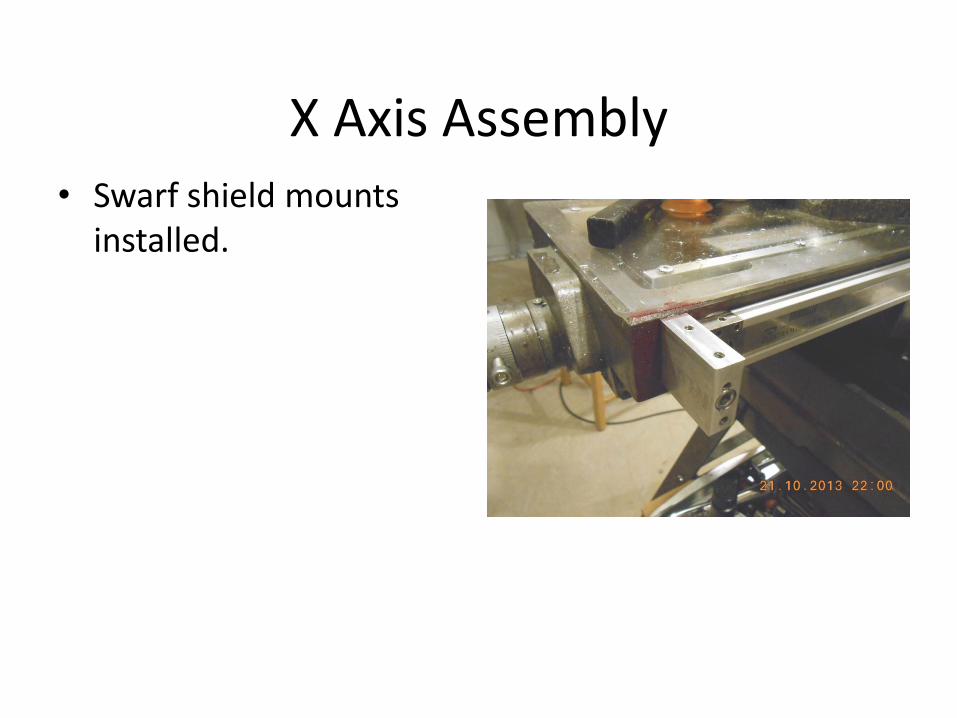
X Axis Assembly • Swarf shield mounts
installed.
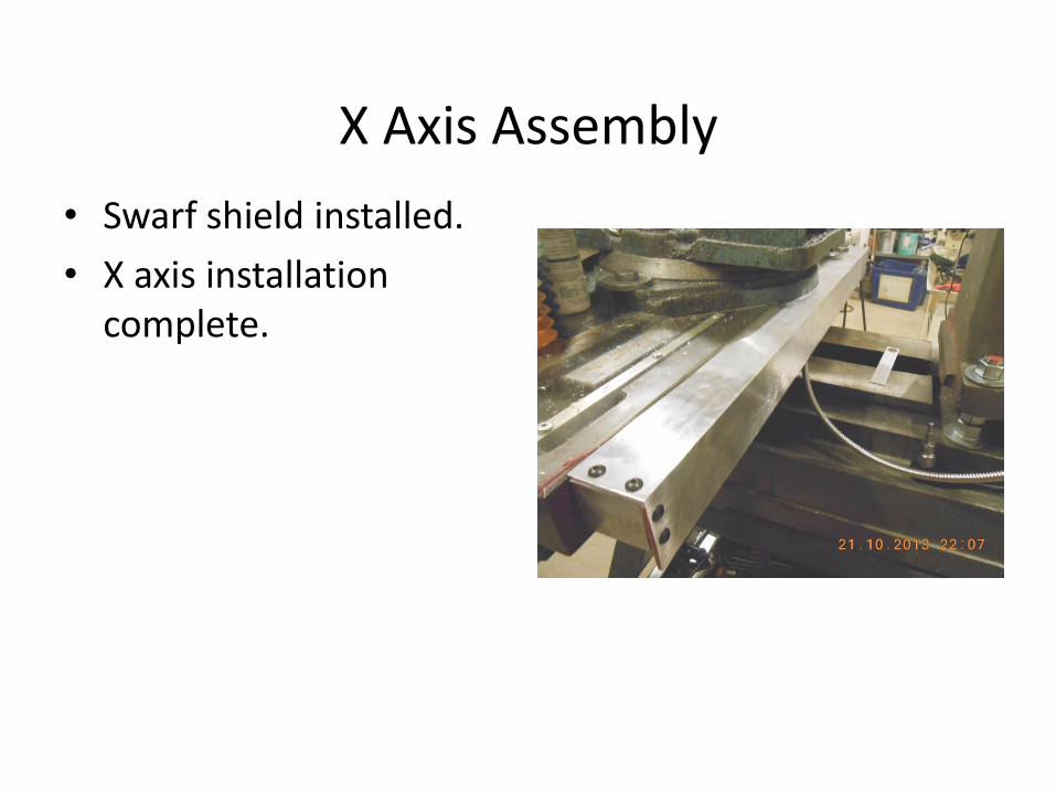
X Axis Assembly
• Swarf shield installed.
• X axis installation complete.

X Axis Space Consumption
• DRO X axis has consumed about ¼ inch of the space available between the vise and the mill column.
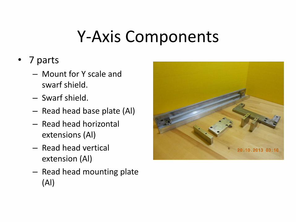
Y-Axis Components • 7 parts
– Mount for Y scale and swarf shield.
– Swarf shield.
– Read head base plate (Al)
– Read head horizontal extensions (Al)
– Read head vertical extension (Al)
– Read head mounting plate (Al)
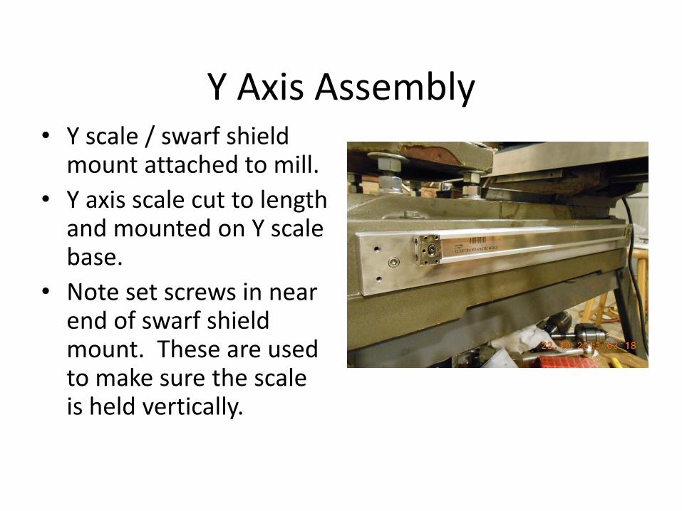
Y Axis Assembly • Y scale / swarf shield
mount attached to mill.
• Y axis scale cut to length and mounted on Y scale base.
• Note set screws in near end of swarf shield mount. These are used to make sure the scale is held vertically.
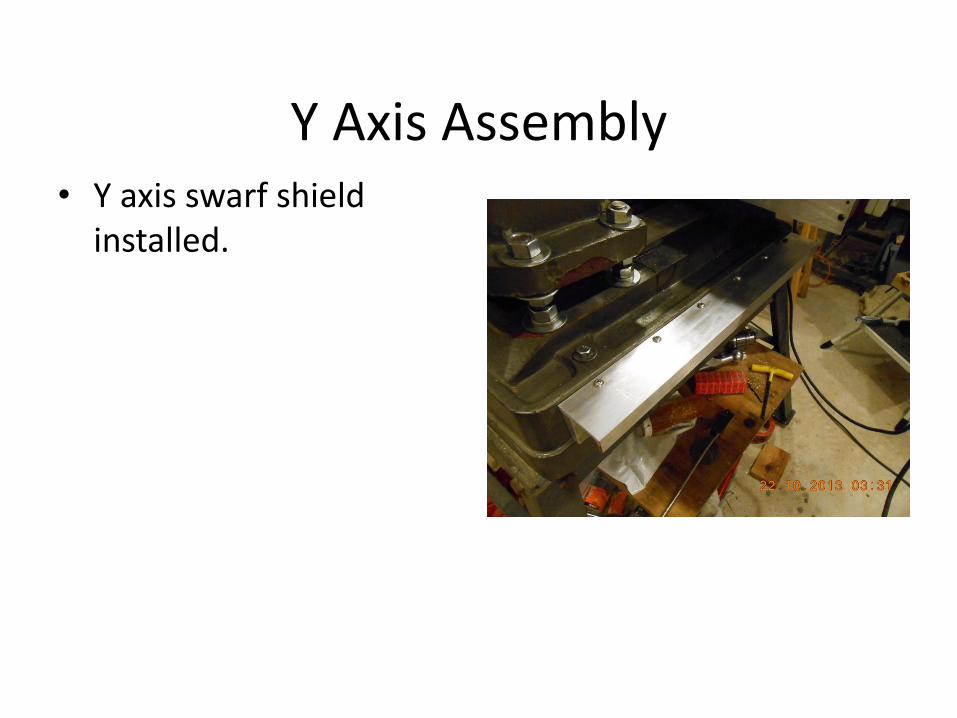
Y Axis Assembly • Y axis swarf shield
installed.
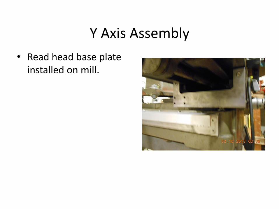
Y Axis Assembly
• Read head base plate installed on mill.
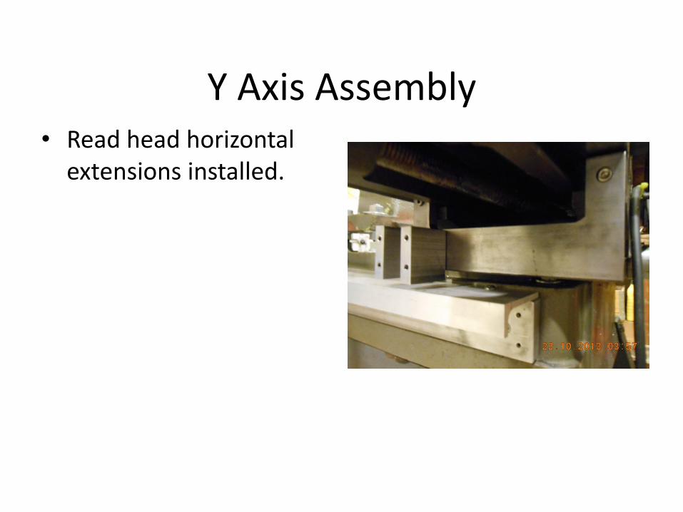
Y Axis Assembly • Read head horizontal
extensions installed.
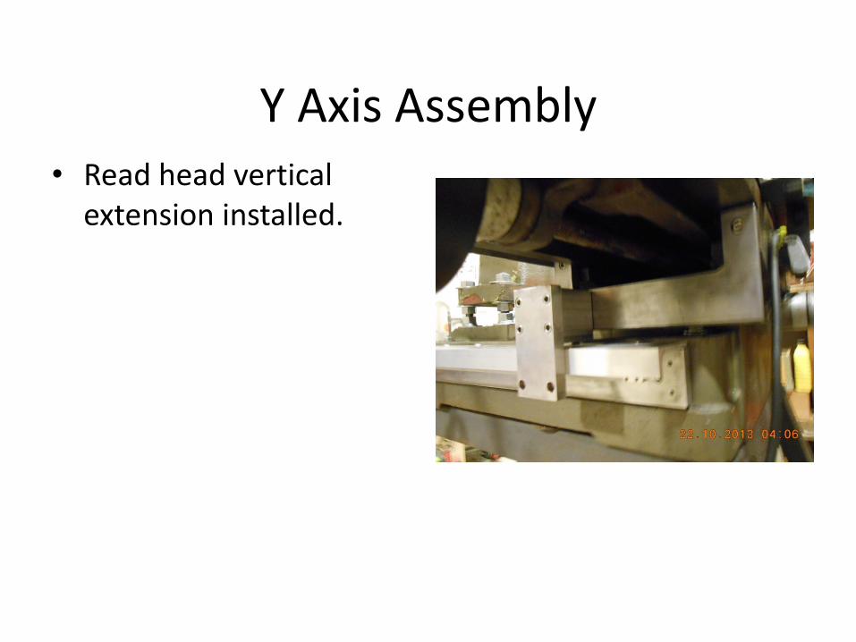
Y Axis Assembly • Read head vertical
extension installed.
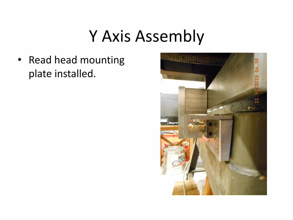
Y Axis Assembly • Read head mounting
plate installed.
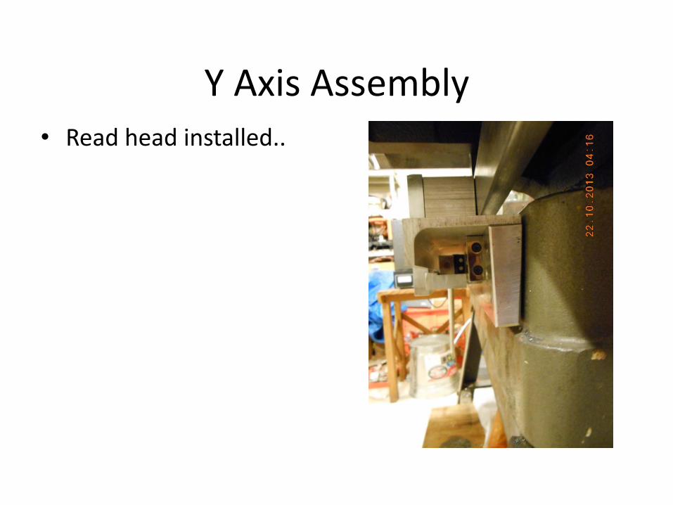
Y Axis Assembly • Read head installed..
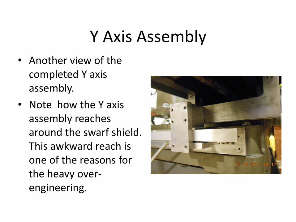
Y Axis Assembly • Another view of the
completed Y axis assembly.
• Note how the Y axis assembly reaches around the swarf shield. This awkward reach is one of the reasons for the heavy over-engineering.
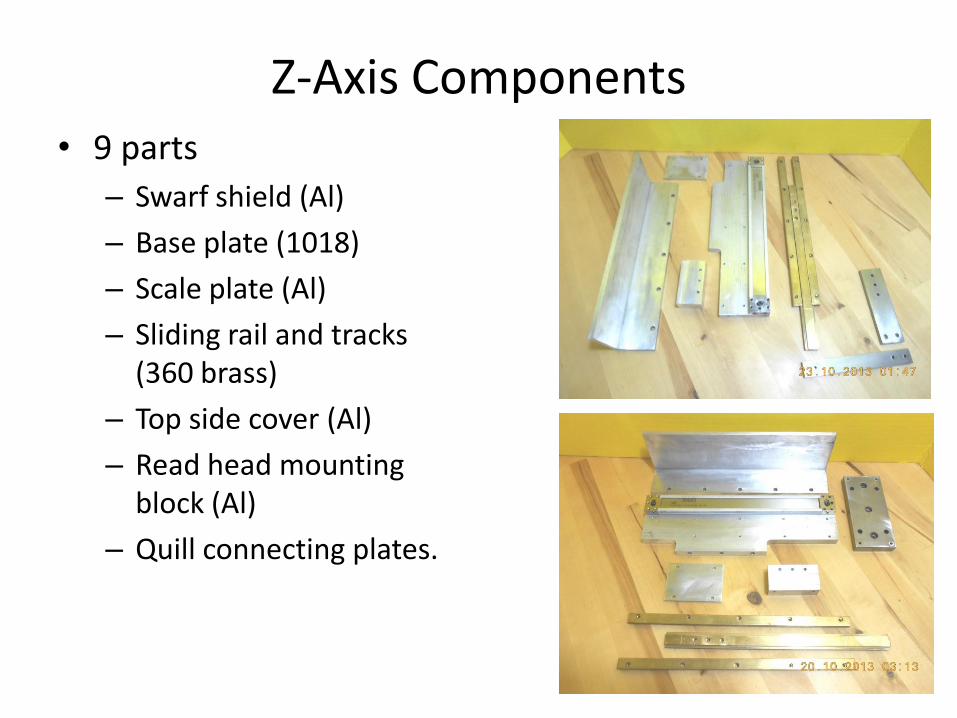
Z-Axis Components • 9 parts
– Swarf shield (Al)
– Base plate (1018)
– Scale plate (Al)
– Sliding rail and tracks (360 brass)
– Top side cover (Al)
– Read head mounting block (Al)
– Quill connecting plates.
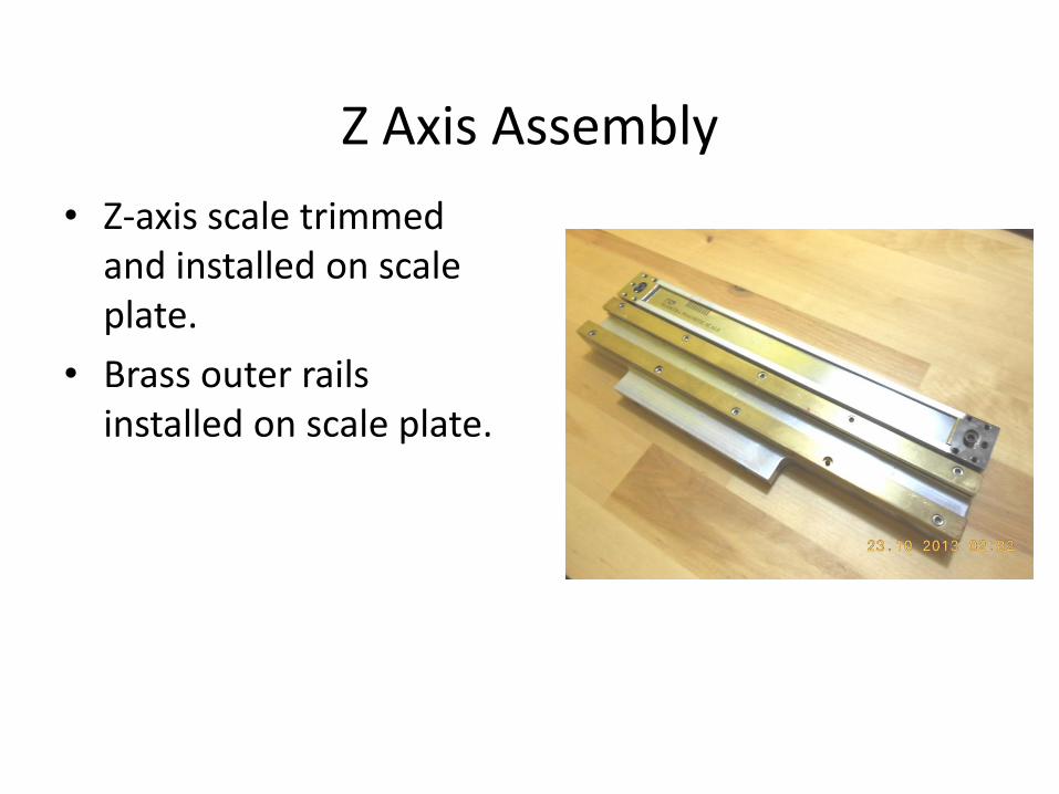
Z Axis Assembly
• Z-axis scale trimmed and installed on scale plate.
• Brass outer rails installed on scale plate.

Z Axis Assembly
• Read head mounting block bolted to sliding rail.
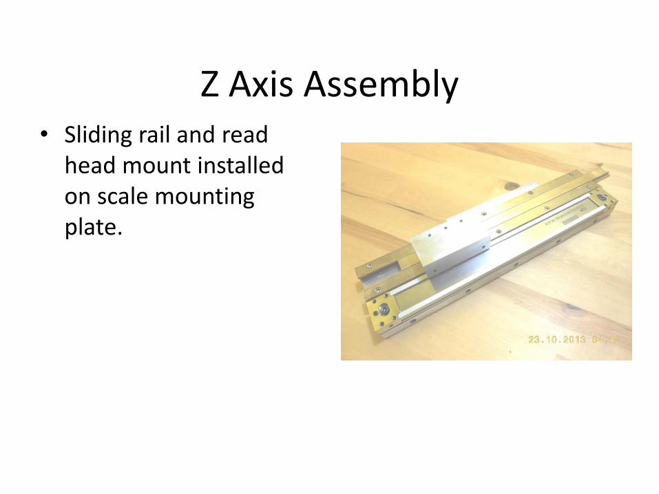
Z Axis Assembly • Sliding rail and read
head mount installed on scale mounting plate.
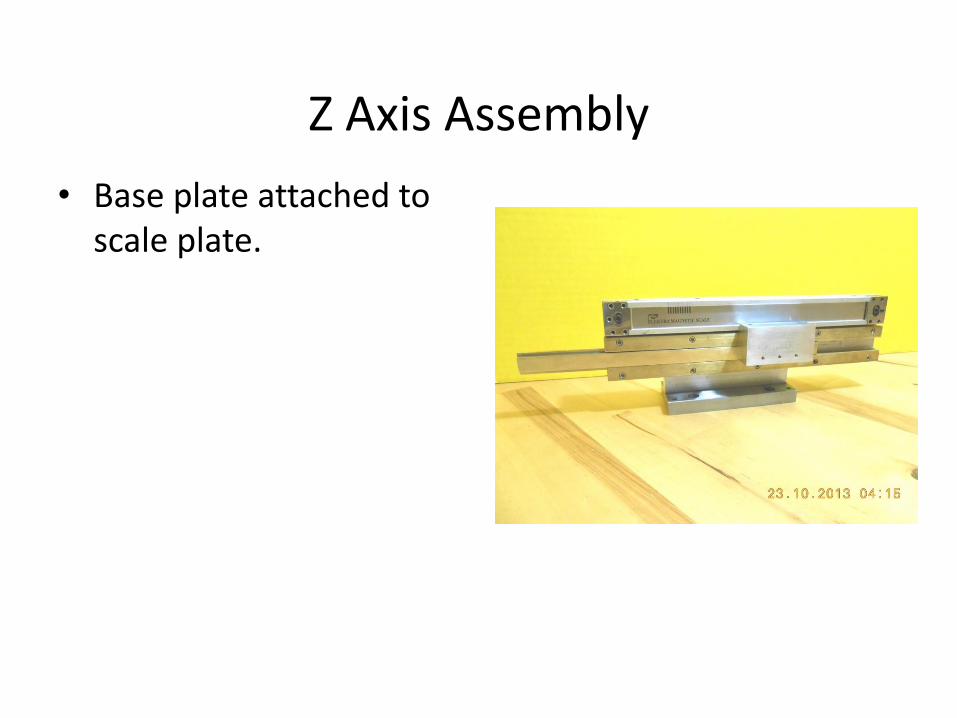
Z Axis Assembly
• Base plate attached to scale plate.
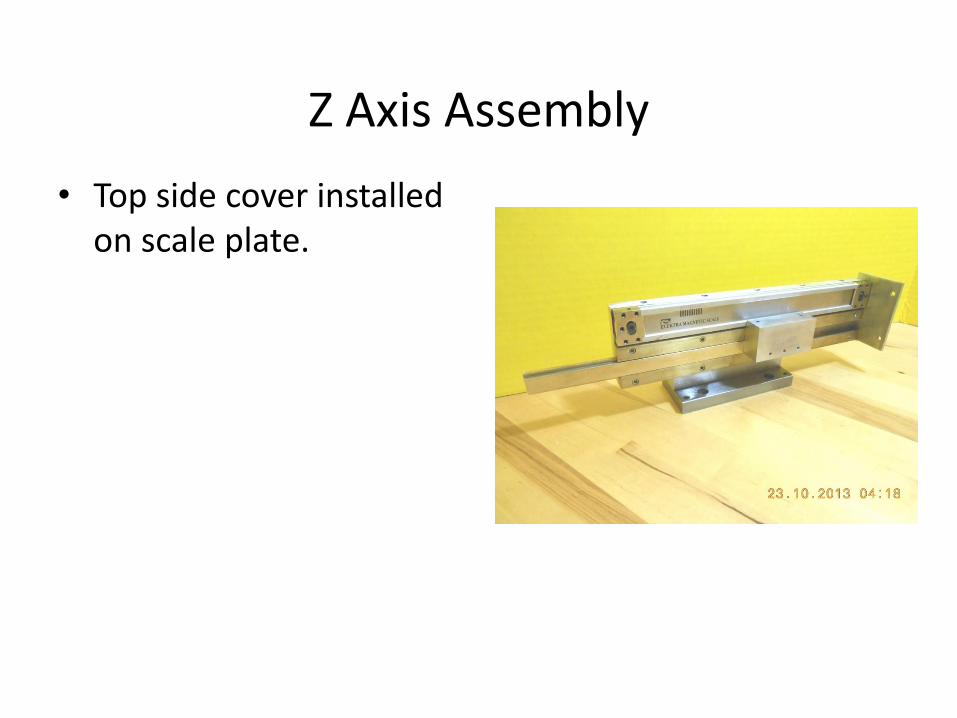
Z Axis Assembly
• Top side cover installed on scale plate.
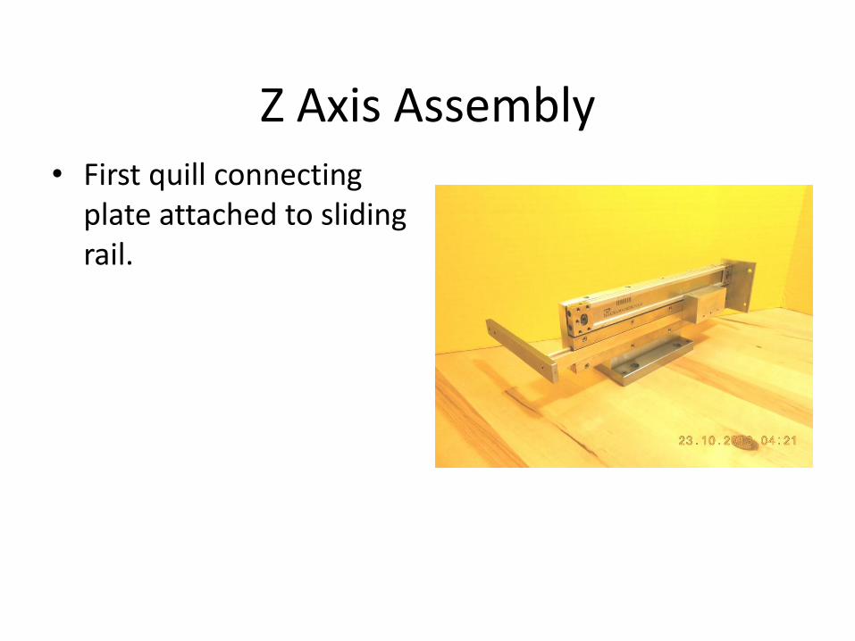
Z Axis Assembly • First quill connecting
plate attached to sliding rail.
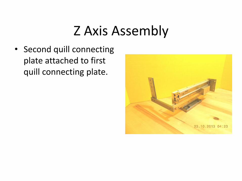
Z Axis Assembly • Second quill connecting
plate attached to first quill connecting plate.
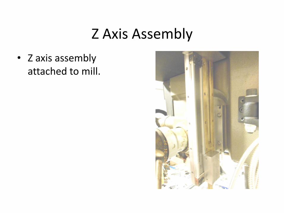
Z Axis Assembly
• Z axis assembly attached to mill.
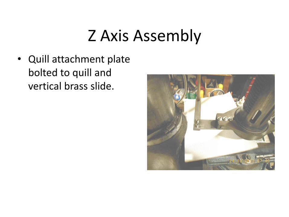
Z Axis Assembly • Quill attachment plate
bolted to quill and vertical brass slide.
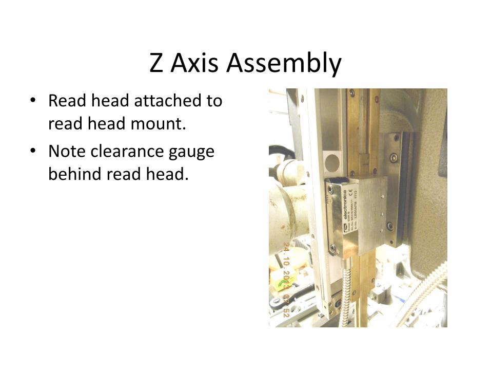
Z Axis Assembly • Read head attached to
read head mount.
• Note clearance gauge behind read head.
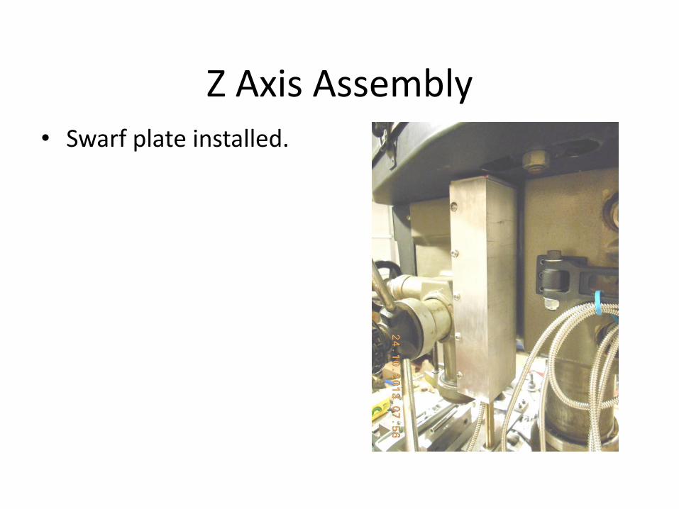
Z Axis Assembly • Swarf plate installed.
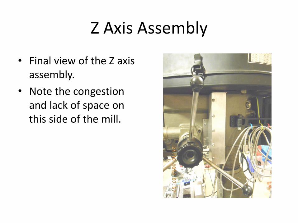
Z Axis Assembly
• Final view of the Z axis assembly.
• Note the congestion and lack of space on this side of the mill.
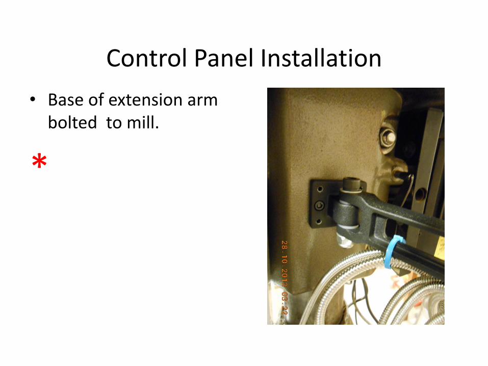
Control Panel Installation
• Base of extension arm bolted to mill.
*
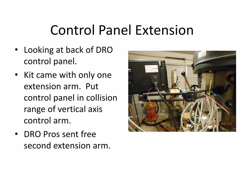
Control Panel Extension • Looking at back of DRO
control panel.
• Kit came with only one extension arm. Put control panel in collision range of vertical axis control arm.
• DRO Pros sent free second extension arm.
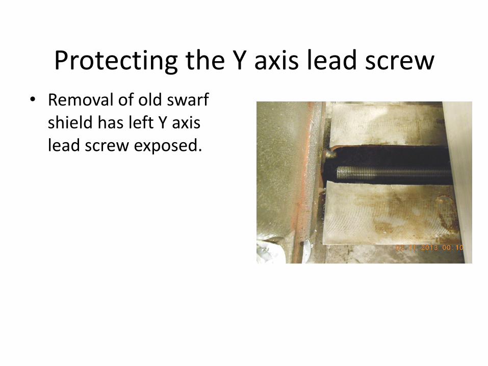
Protecting the Y axis lead screw • Removal of old swarf
shield has left Y axis lead screw exposed.
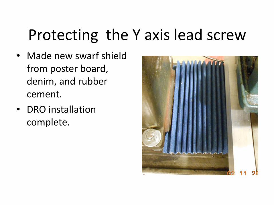
Protecting the Y axis lead screw • Made new swarf shield
from poster board, denim, and rubber cement.
• DRO installation complete.
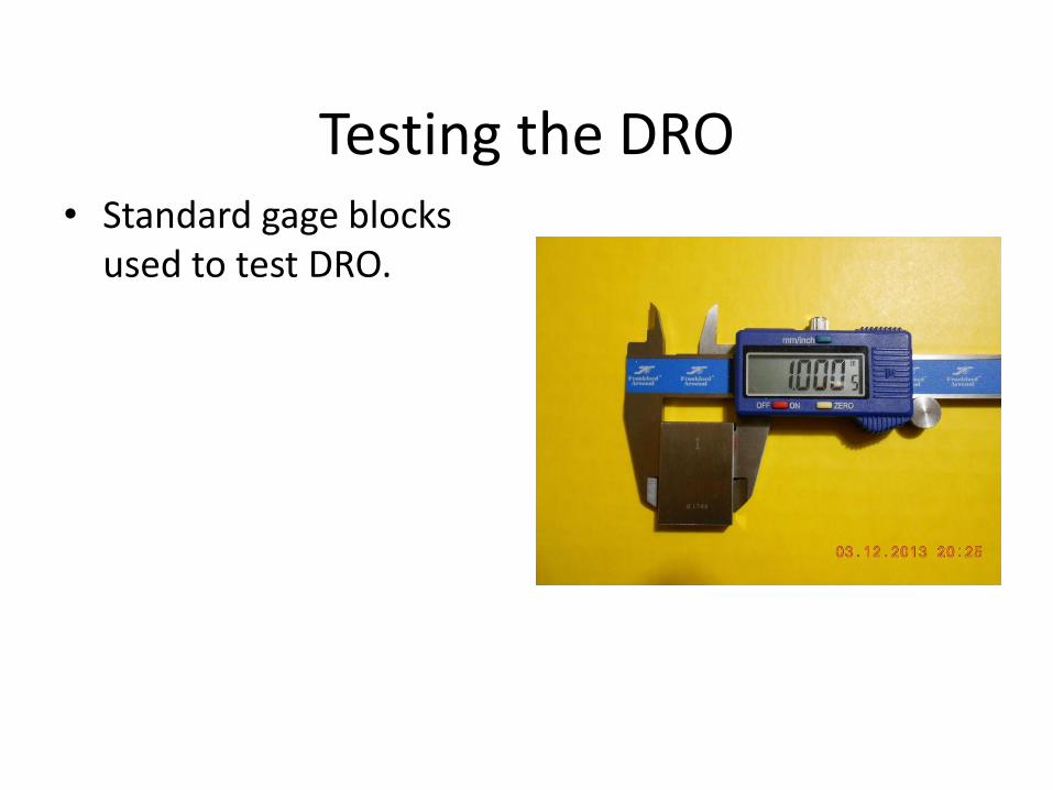
Testing the DRO • Standard gage blocks
used to test DRO.
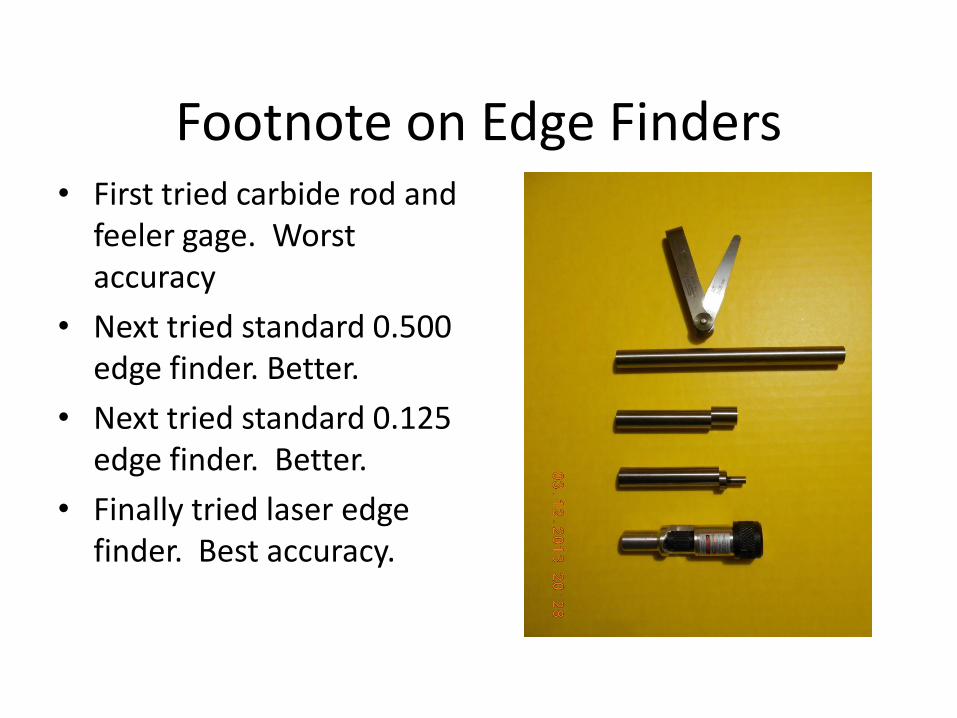
Footnote on Edge Finders • First tried carbide rod and
feeler gage. Worst accuracy
• Next tried standard 0.500 edge finder. Better.
• Next tried standard 0.125 edge finder. Better.
• Finally tried laser edge finder. Best accuracy.
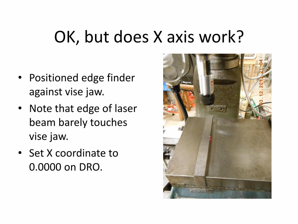
OK, but does X axis work?
• Positioned edge finder against vise jaw.
• Note that edge of laser beam barely touches vise jaw.
• Set X coordinate to 0.0000 on DRO.
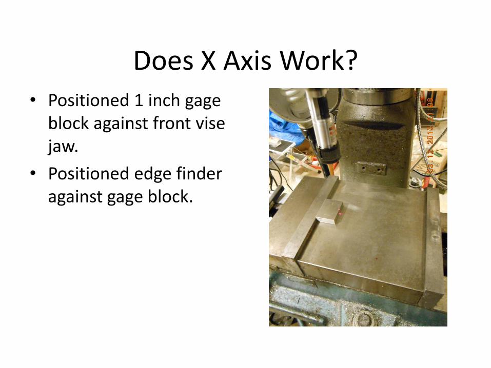
Does X Axis Work? • Positioned 1 inch gage
block against front vise jaw.
• Positioned edge finder against gage block.
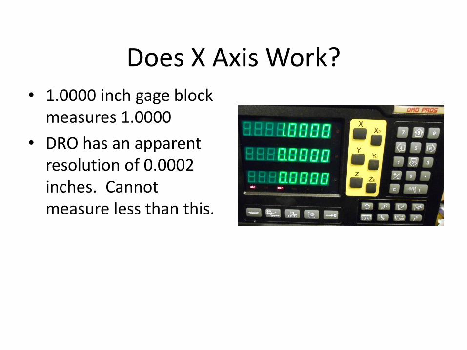
Does X Axis Work? • 1.0000 inch gage block
measures 1.0000
• DRO has an apparent resolution of 0.0002 inches. Cannot measure less than this.
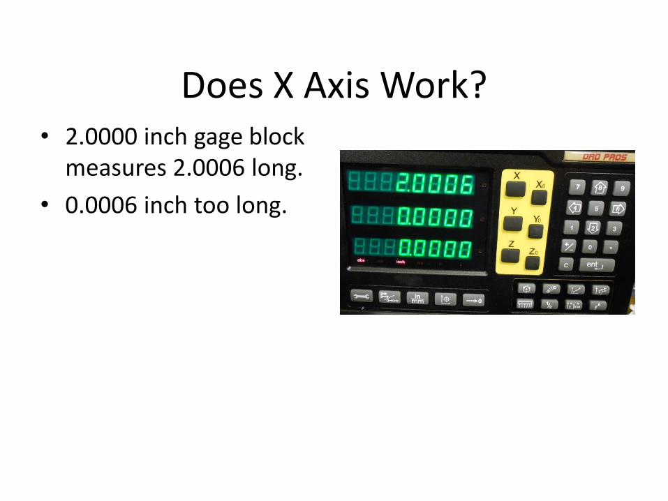
Does X Axis Work? • 2.0000 inch gage block
measures 2.0006 long.
• 0.0006 inch too long.
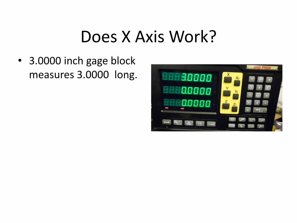
Does X Axis Work? • 3.0000 inch gage block
measures 3.0000 long.
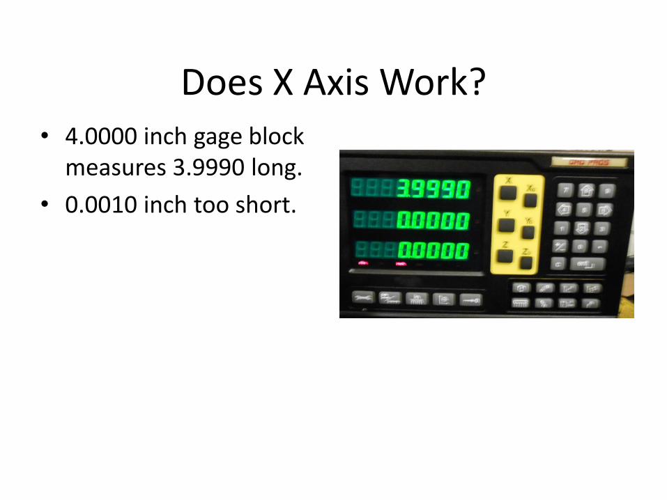
Does X Axis Work? • 4.0000 inch gage block
measures 3.9990 long.
• 0.0010 inch too short.
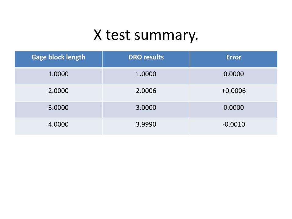
X test summary. Gage block length DRO results Error
1.0000 1.0000 0.0000
2.0000 2.0006 +0.0006
3.0000 3.0000 0.0000
4.0000 3.9990 -0.0010
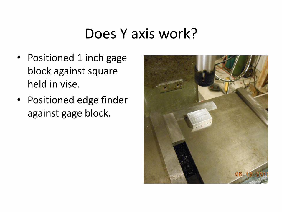
Does Y axis work?
• Positioned 1 inch gage block against square held in vise.
• Positioned edge finder against gage block.
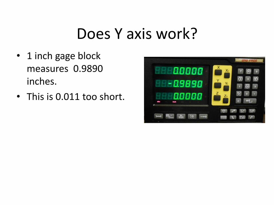
Does Y axis work? • 1 inch gage block
measures 0.9890 inches.
• This is 0.011 too short.
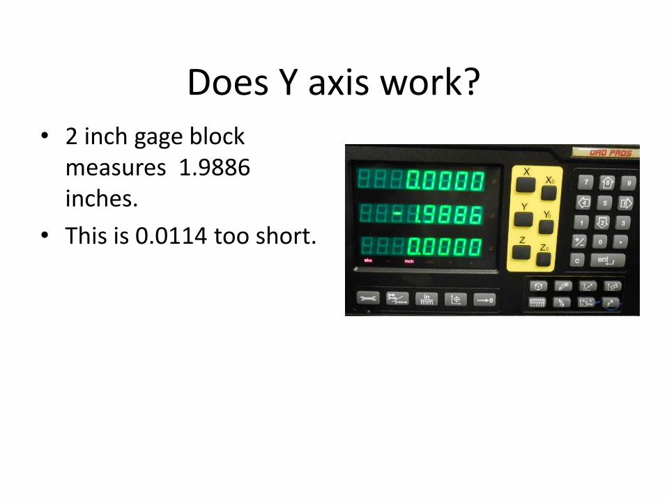
Does Y axis work? • 2 inch gage block
measures 1.9886 inches.
• This is 0.0114 too short.
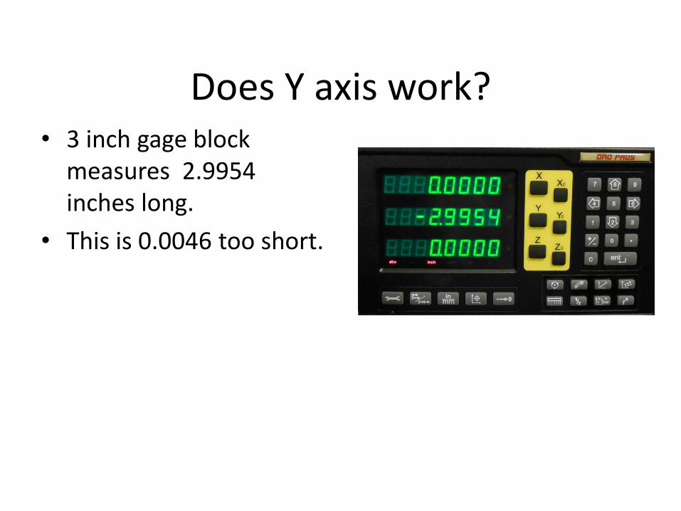
Does Y axis work? • 3 inch gage block
measures 2.9954 inches long.
• This is 0.0046 too short.
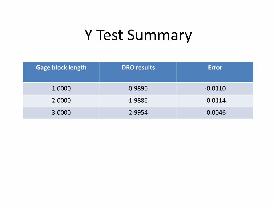
Y Test Summary
Gage block length DRO results Error
1.0000 0.9890 -0.0110
2.0000 1.9886 -0.0114
3.0000 2.9954 -0.0046
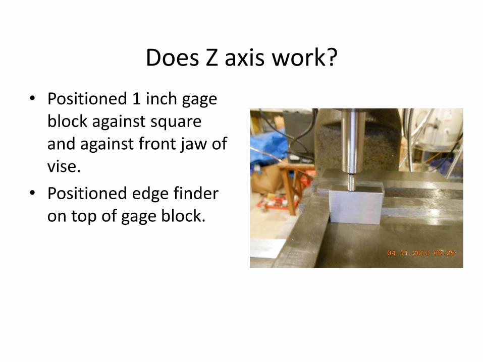
Does Z axis work?
• Positioned 1 inch gage block against square and against front jaw of vise.
• Positioned edge finder on top of gage block.
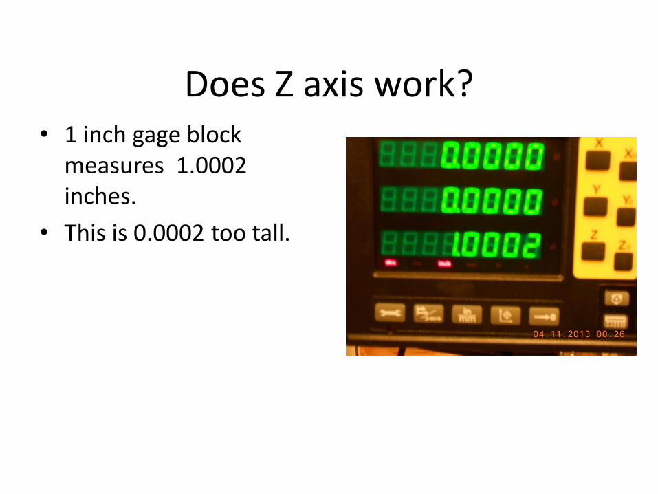
Does Z axis work? • 1 inch gage block
measures 1.0002 inches.
• This is 0.0002 too tall.
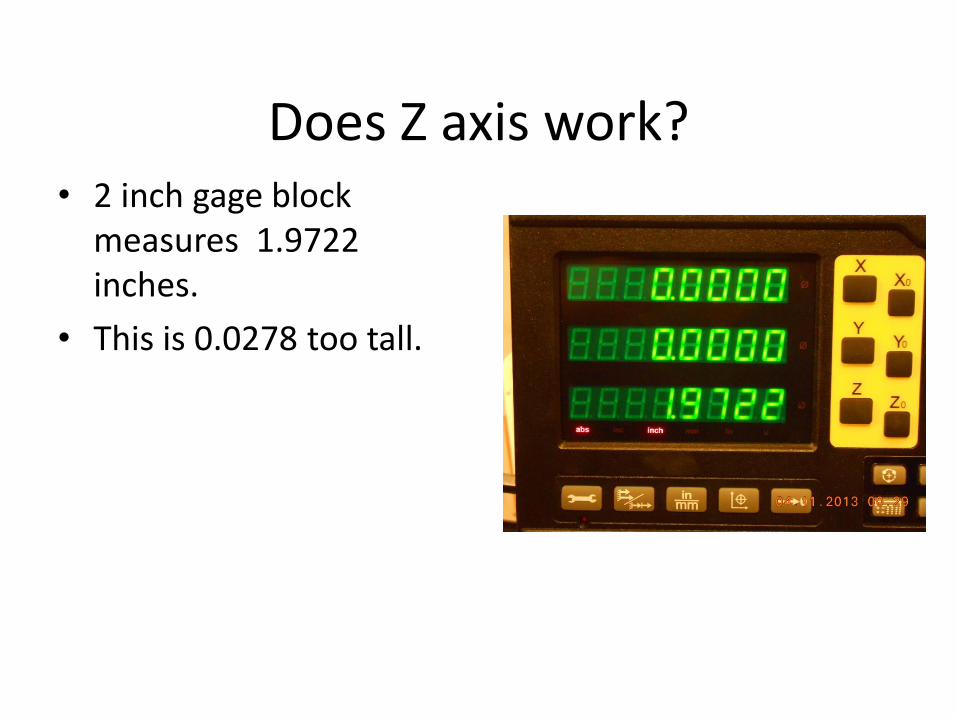
Does Z axis work? • 2 inch gage block
measures 1.9722 inches.
• This is 0.0278 too tall.
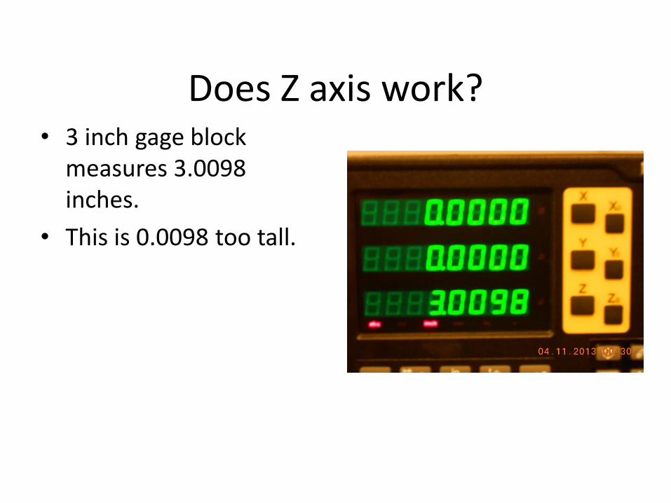
Does Z axis work? • 3 inch gage block
measures 3.0098 inches.
• This is 0.0098 too tall.
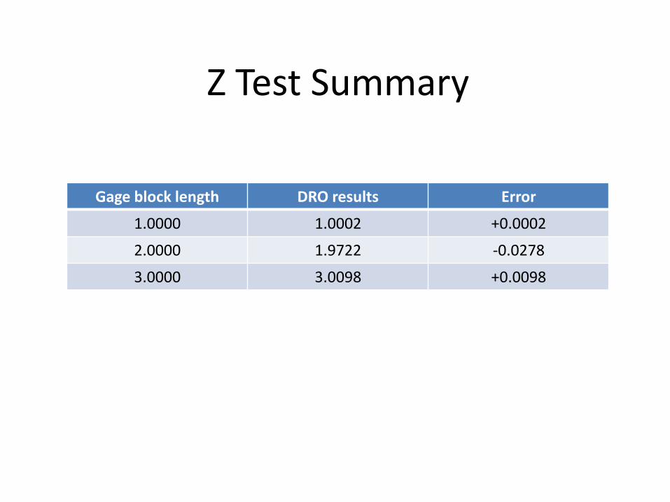
Z Test Summary
Gage block length DRO results Error
1.0000 1.0002 +0.0002
2.0000 1.9722 -0.0278
3.0000 3.0098 +0.0098
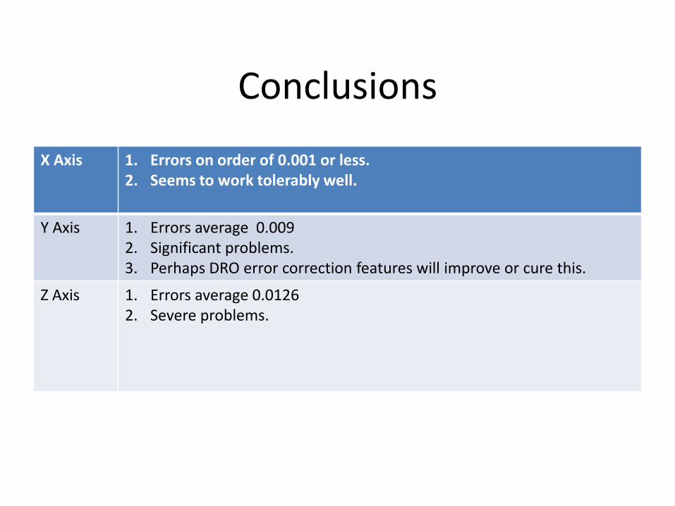
Conclusions
X Axis 1. Errors on order of 0.001 or less. 2. Seems to work tolerably well.
Y Axis 1. Errors average 0.009 2. Significant problems. 3. Perhaps DRO error correction features will improve or cure this.
Z Axis 1. Errors average 0.0126 2. Severe problems.

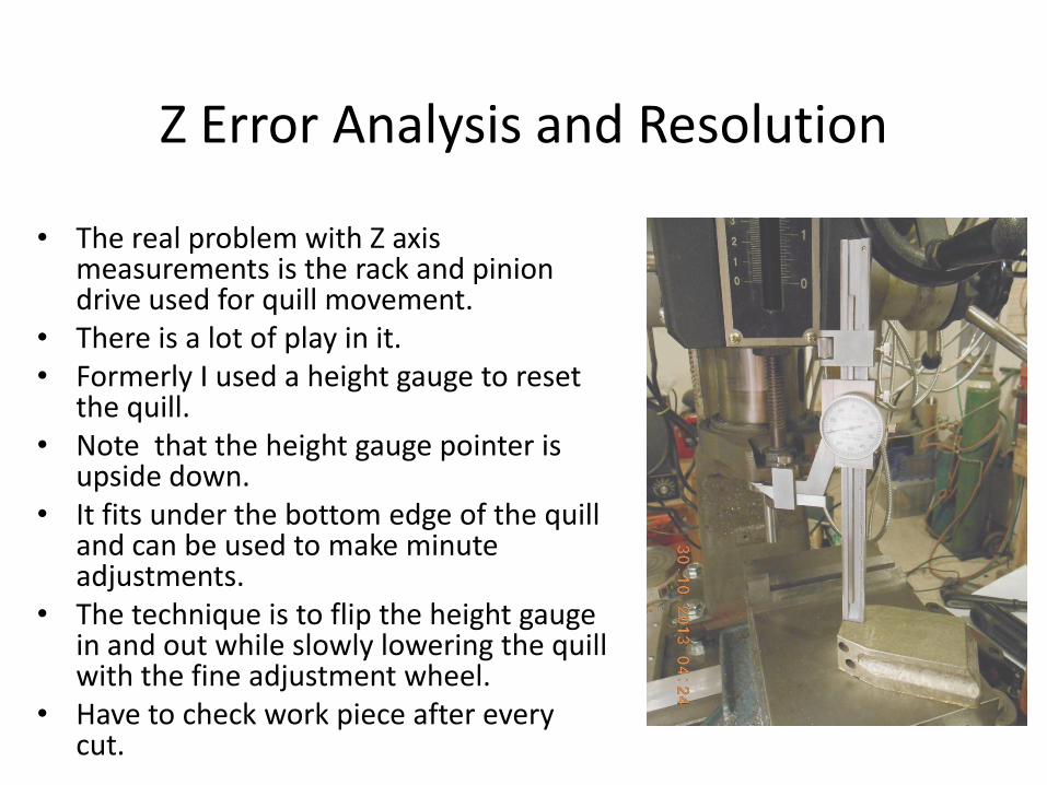
Z Error Analysis and Resolution
• The real problem with Z axis measurements is the rack and pinion drive used for quill movement.
• There is a lot of play in it. • Formerly I used a height gauge to reset
the quill. • Note that the height gauge pointer is
upside down. • It fits under the bottom edge of the quill
and can be used to make minute adjustments.
• The technique is to flip the height gauge in and out while slowly lowering the quill with the fine adjustment wheel.
• Have to check work piece after every cut.
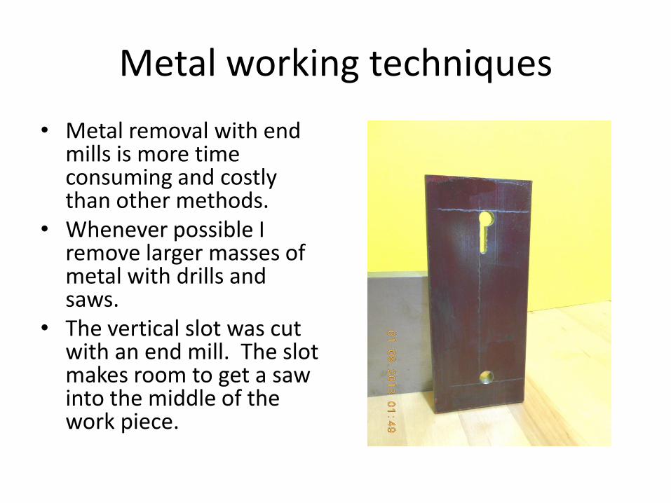
Metal working techniques
• Metal removal with end mills is more time consuming and costly than other methods.
• Whenever possible I remove larger masses of metal with drills and saws.
• The vertical slot was cut with an end mill. The slot makes room to get a saw into the middle of the work piece.
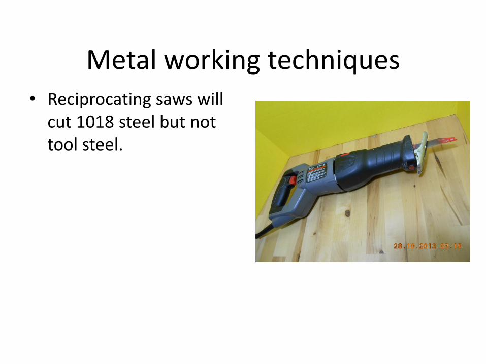
Metal working techniques • Reciprocating saws will
cut 1018 steel but not tool steel.
Metal Working Techniques
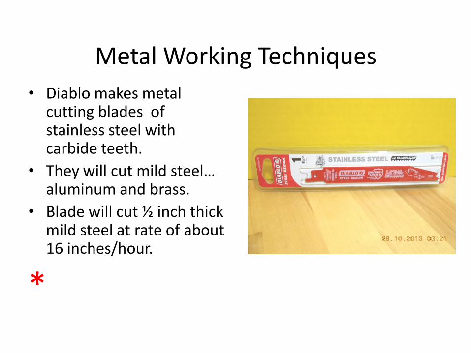
• Diablo makes metal cutting blades of stainless steel with carbide teeth.
• They will cut mild steel… aluminum and brass.
• Blade will cut ½ inch thick mild steel at rate of about 16 inches/hour.
*
Metal Working Techniques
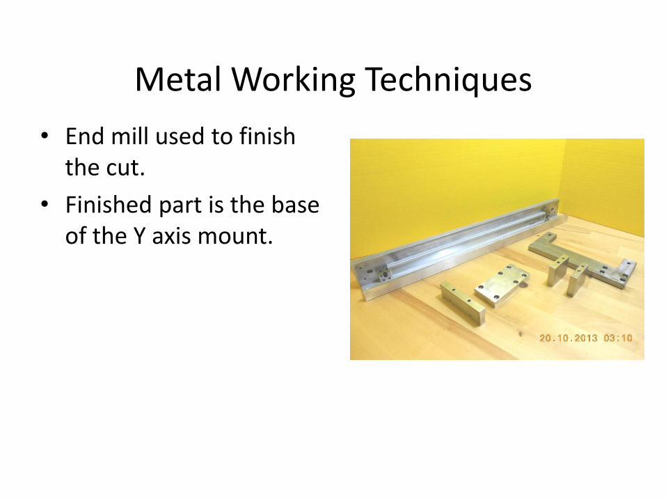
• End mill used to finish the cut.
• Finished part is the base of the Y axis mount.
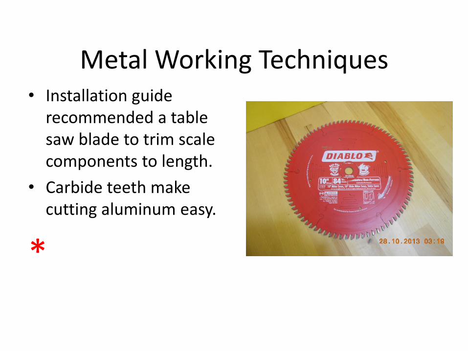
Metal Working Techniques • Installation guide
recommended a table saw blade to trim scale components to length.
• Carbide teeth make cutting aluminum easy.
*
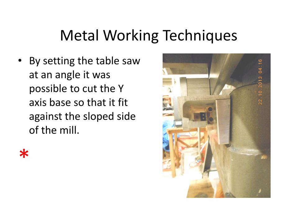
Metal Working Techniques
• By setting the table saw at an angle it was possible to cut the Y axis base so that it fit against the sloped side of the mill.
*
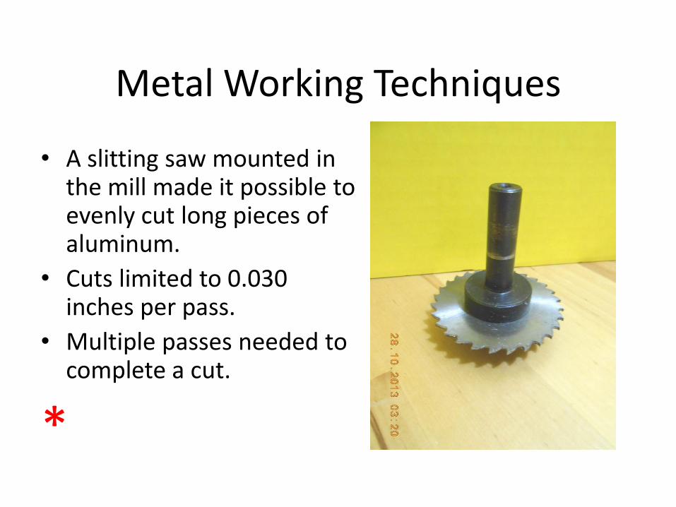
Metal Working Techniques
• A slitting saw mounted in the mill made it possible to evenly cut long pieces of aluminum.
• Cuts limited to 0.030 inches per pass.
• Multiple passes needed to complete a cut.
*
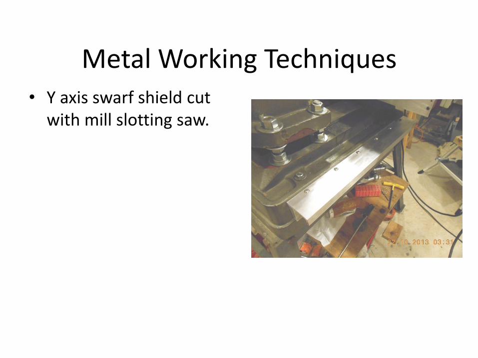
Metal Working Techniques • Y axis swarf shield cut
with mill slotting saw.
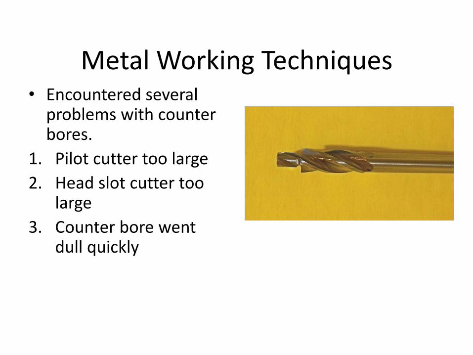
Metal Working Techniques • Encountered several
problems with counter bores.
1. Pilot cutter too large
2. Head slot cutter too large
3. Counter bore went dull quickly
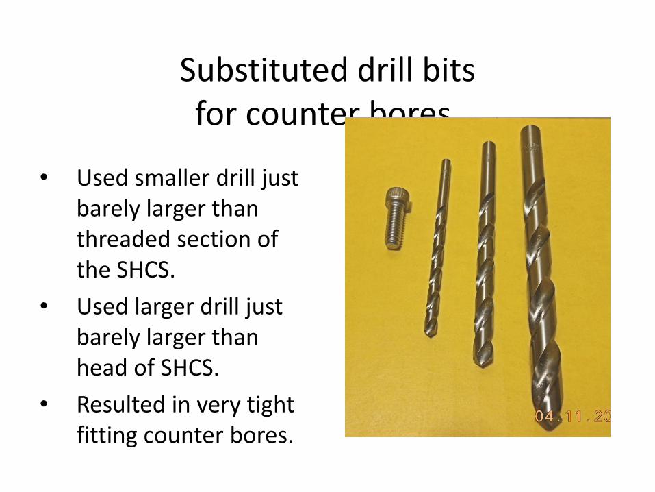
Substituted drill bits for counter bores.
• Used smaller drill just barely larger than threaded section of the SHCS.
• Used larger drill just barely larger than head of SHCS.
• Resulted in very tight fitting counter bores.
Z Error Analysis and Resolution
• The real problem with Z axis measurements is the rack and pinion drive used for quill movement.
• There is a lot of play in it. • Formerly I used a height gauge to reset
the quill. • Note that the height gauge pointer is
upside down. • It fits under the bottom edge of the quill
and can be used to make minute adjustments.
• The technique is to flip the height gauge in and out while slowly lowering the quill with the fine adjustment wheel.
• Have to check work piece after every cut.
Questions
• Does this installation seem reasonable?
• Any suggestions for fixing the problems?
Future Problems
• Mill stand is a weak and flimsy affair made of angle iron and sheet metal.
• One leg is slowly giving way. • Mill looses level after 2 weeks of use. • Mill looses tram after 1 hour of use. • Need new much heavier duty mill stand. • New stand to have:
– table top of 2 sheets of ½ inch steel plate. – legs of 4 inch square mild steel ¼ inch thick. – heavy duty pivoting feet that have leveling screw.

The End