Embed Size (px)
Citation preview
Adding a Second Ku-Band Antenna to the International Space Station
Authors: Chuck G. Dusold, Corey Thacker, and Sundeep Kwatra
Abstract - The International Space Station, as originally developed, used the Ku-Band Tracking and Data Relay Satellite System communications link to transmit non-critical data to the ground. Since becoming operational, the use for the link evolved to include additional services that, although also not critical, were deemed to be necessary for the crew. The external Ku-Band Antennas were designed for transport to the ISS in the shuttle cargo bay and thus are not suitable for manifesting on any current cargo vehicle. The original intent was to stow two spare antennas on orbit in a protective container until such time as they were needed to replace a failing unit which is a long and complicated process due to the complexity of the removal and replacement procedure. The Boeing Company proposed manifesting one of those spare antennas in an operable configuration eliminating the need for an Extravehicular Activity (EVA) to correct the first failure and as such minimizing the time to hours rather than weeks required to restore the Ku-Band communications link after failures. After the first failure, an EVA would be scheduled to replace the failed antenna with the stowed spare antenna. Because the “hot” spare is activated internal to the ISS, the replacement of the failed unit can be done when convenient rather than in haste. This paper describes the methodology used to locate a suitable site to add a new antenna mast to the ISS as well the process followed to fabricate, deliver and install the new interface hardware. Because this was not planned when the ISS was originally designed, structural, power, data and Intermediate Frequency signal connections had to be found for use. With the movement of the P6 solar array element from the initial location in the center zenith location of the ISS to the end of the port side of the truss and concurrent relocation of one string of S-Band communications assets, there were candidate power, data and structural connections available on the Z1 Truss. The engineering team evaluated these residual interfaces for use and designed cabling and structural elements for the candidate interfaces. The antenna was recently installed on ULF-4 and has completed a preliminary checkout. Included in this check out were evaluation of the power level received from the TDRS and evaluation of the gimbal position feedback for consideration in the static bias pointing matrix. This process demonstrates the ability to modify and upgrade manned space vehicles as either need or technology requires.
1 American Institute of Aeronautics and Astronautics
Adding a Second Ku-Band Antenna to the International Space Station
Charles G. Dusold The Boeing Company, Huntsville, AL, 35813
Sundeep S. Kwatra NASA, Houston, Texas, 77059
and
Corey M. Thacker The Boeing Company, Houston, Texas, 77059
The International Space Station, as originally developed, uses the Ku-Band Tracking and
Data Relay Satellite System communications link to transmit non-critical data to the ground. Since becoming operational, the use for the link evolved to include additional services that, although also not critical, were deemed to be necessary for the crew. The external Ku-Band Antennas were designed for transport to the ISS in the shuttle cargo bay and thus are not suitable for manifesting on any current cargo vehicle. The original intent was to stow two spare antennas on-orbit in a protective container until such time as they were needed to replace a failing unit which is a long and complicated process due to the complexity of the removal and replacement procedure. The Boeing Company proposed manifesting one of those spare antennas in an operable configuration eliminating the need for an Extravehicular Activity (EVA) to correct the first failure and as such minimizing the time to hours rather than weeks required to restore the Ku-Band communications link after potential failures. After the first failure, an EVA would be scheduled to replace the failed antenna with the stowed spare antenna. Because the “hot” spare is activated internal to the ISS, the replacement of the failed unit can be done when convenient rather than in haste. This paper describes the methodology used to locate a suitable site to add a new antenna mast to the ISS as well the process followed to fabricate, deliver and install the new interface hardware. Because this was not planned when the ISS was originally designed, structural, power, data and Intermediate Frequency signal connections had to be found for use. With the movement of the P6 solar array element from the initial location in the center zenith location of the ISS to the end of the port side of the truss and the concurrent relocation of one string of S-Band communications assets, there were candidate power, data and structural connections available on the Z1 Truss. The engineering team evaluated these residual interfaces for use and designed cabling and structural elements for the candidate interfaces. The antenna was recently installed on the ULF-4 shuttle mission and has completed a preliminary checkout. Included in this checkout were evaluation of the power level received from the TDRS and evaluation of the gimbal position feedback for consideration in the static bias pointing matrix. This process demonstrates the ability to modify and upgrade manned space vehicles as either need or technology requires.
I. Introduction During the spring of 2007, the International Space Station engineering organizations performed an
assessment of the need to pre-position spares on-orbit before the scheduled retirement of the Space Shuttle Transportation System in late 2010. The goal was to determine the number of spare units required to support ISS operations through the year 2020. Using the Mean Time Between Failures (MTBF) prediction based on the Bayesian model for each unit, the number of required spares was determined and Orbital Replaceable Units (ORUs) were assessed for their ability to be transported to ISS using one of the planned cargo transport vehicles.
2 American Institute of Aeronautics and Astronautics
The ISS Ku-Band Antenna Group consists of the Ku-Band Space-to-Ground Antenna (SGANT), the Ku-Band Space-to-Ground Transmitter/Receiver Controller (SGTRC) and the Ku-Band Boom. The Ku-Band Antenna calculation indicated that two replacement antennas would be required to provide service through the target date.
Nominally, ISS Astronauts train for EVA replacement of critical, high priority external ORUs, such as the S-Band Antenna Group, which is critical to command and monitor the station. For repairs not considered to be critical, NASA provides specific steps to the crew after a failure. A critical failure is one that would put the safety of the Crew or ISS in jeopardy, and while Ku-Band provides high-rate communications, it does not fall in this category. Based on the low criticality of the repair, the time between the failure and the repair is several weeks at best, normally longer. During the time that the Ku-Band Communications System has been active, NASA has added some crew comfort features to the link including Internet Protocol phone capabilities, private video, and medical conferencing. Due to the higher bandwidth capabilities relative to the S-Band link, operations utilize the Ku-Band system for faster file uplinks. While not life threatening, the loss of this and other features for an extended period of time was considered to be a significant inconvenience to the crew and flight operations.
The baseline plan for the stowage of the spare antennas on-orbit called for minimal protection with power and data connectivity to the stored units to provide thermal conditioning as well as the ability to periodically check the unit’s health and status. One of the authors proposed providing a location where the spare Ku-Band RF Group was essentially ready for operation with only internal cable routing activities required. At the time when the suggestion was made, it was noted that the ISS was not designed for this kind of upgrade. This paper traces the effort to locate a suitable location for power, data and structural connectivity for the new Ku-Band RF Group and includes the delivery, integration, and test of the equipment on the ISS.
II. Overview of analysis and conceptual design
A. Connectivity analysis The design documentation for the United States On-orbit Segment (USOS) was reviewed for fiber optic
and copper transmission paths penetrating the pressure bulkhead. The ISS program did not originally include a plan during the design phase for spare connectors between the internal vehicle volume and the external vehicle. As a result, some connector pin locations that were used as temporary connection locations during assembly were in fact spare connections available for use.
Power distribution on the external structure originates from externally mounted Remote Power Controller Modules (RPCMs) and is distributed to external Orbital Replaceable Units (ORUs), payload attach locations, and external television camera ports. Power availability cannot be easily changed from the pre-integrated wiring. Therefore, an early constraint evolved requiring installation of the unit in close proximity to existing and unreserved power connections.
The ISS uses a total of twenty four transmission lines for the purpose of transferring Radio Frequency signals from the internal volume to the external surface. The Ku-Band system uses two intermediate frequency (IF) transmissions, one for forward link data and one for return link data, between the internally mounted Space to Ground Modem and the externally mounted Space to Ground Transmitter/Receiver/Controller. Eight are used by the GPS antennas for connection to the Space Integrated Global Positioning System/ Inertial Navigation System (SIGI) unit and two are used for the External Wireless Instrumentation System. Four transmission lines are used for two way radio frequency (RF) transmissions between the Space to Space Communications System’s internally mounted radio and the four external antennas. Because the second pair of UHF antennas was added after the initial pair was activated, a pair of connectors were used to loop back the unused RF signals to 50 ohm terminating loads inside the ISS. As a result, there were an additional 10 unassigned ports that could be utilized for the new Ku-Band RF Antenna Group.
Control of the external hardware is accomplished using the existing 1553 digital buses. These originate both internally from the command and control Multiplexer/Demultiplexers (MDMs) and externally from subsystem specific MDMs. High rate data connections are supplied to the external payload attach points and are the only external locations that are available. Finally, there are video fiber distribution lines from the internal lab video switches that are routed to the external television camera ports by external video switches.
3 American Institute of Aeronautics and Astronautics
B. Structural attach points Because the Ku-Band Antenna is a large articulating unit with closed loop tracking capability, it was
necessary to find a location providing a rigid attach point. To ensure stability in the control system, the antenna mast requires a 20 Hz structural stiffness. This is based on analysis performed in the early 1990s by Boeing Huntington Beach during the design of the current Ku antenna mast and it requires bolting to a hard point currently in existence on the vehicle. The points that can provide this stiffness include the Payload Attach Points, the External TV Camera Group ports, the S-Band antenna attach points, the S-Band antenna storage location, the S-Band antenna launch attach point on Z1, the top of the Ku-Band mast, the Ku TRC attach point, the Ku launch storage location and trunnion pins at various locations. The trunnion pins are used to mount the pre-integrated truss segments in the Space Shuttle Orbiter cargo bay during launch. They are structurally stiff attachment points and were considered to be excellent prospects for mounting the antenna.
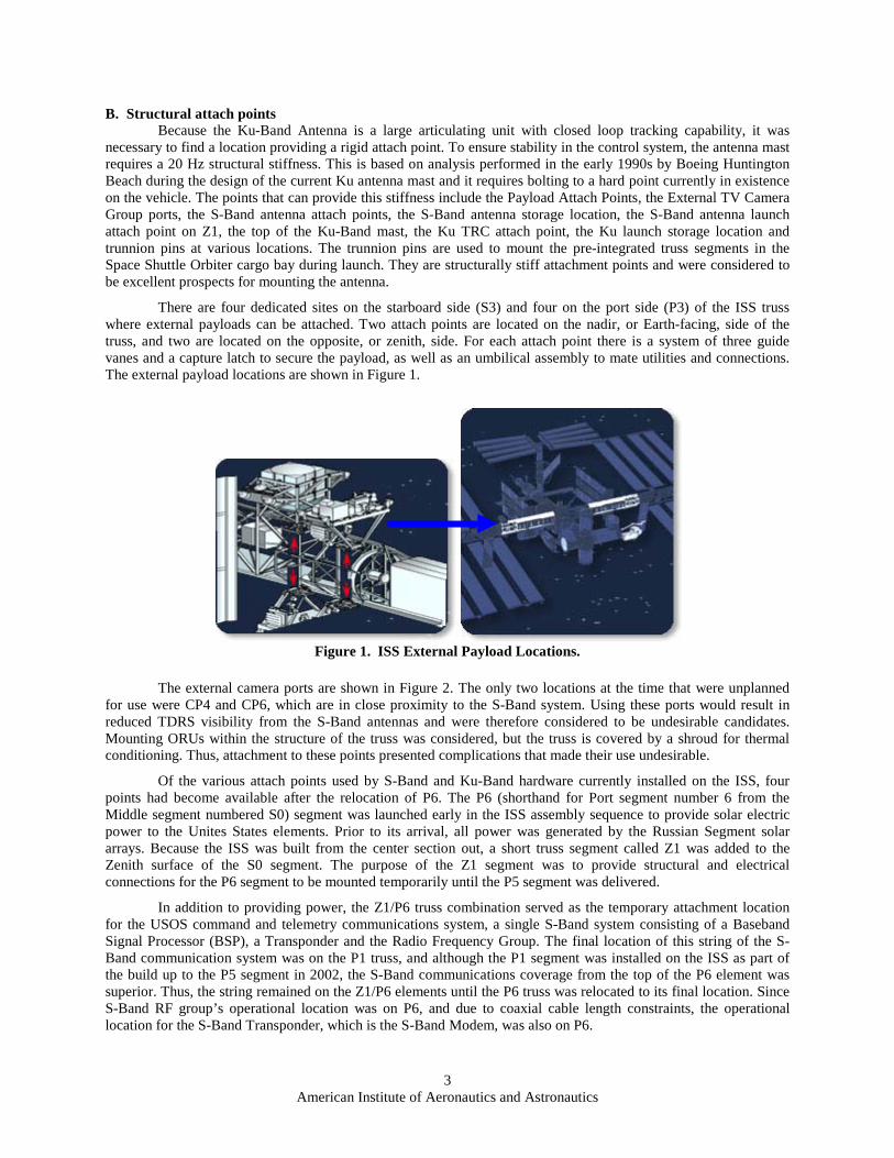
There are four dedicated sites on the starboard side (S3) and four on the port side (P3) of the ISS truss where external payloads can be attached. Two attach points are located on the nadir, or Earth-facing, side of the truss, and two are located on the opposite, or zenith, side. For each attach point there is a system of three guide vanes and a capture latch to secure the payload, as well as an umbilical assembly to mate utilities and connections. The external payload locations are shown in Figure 1.
Figure 1. ISS External Payload Locations.
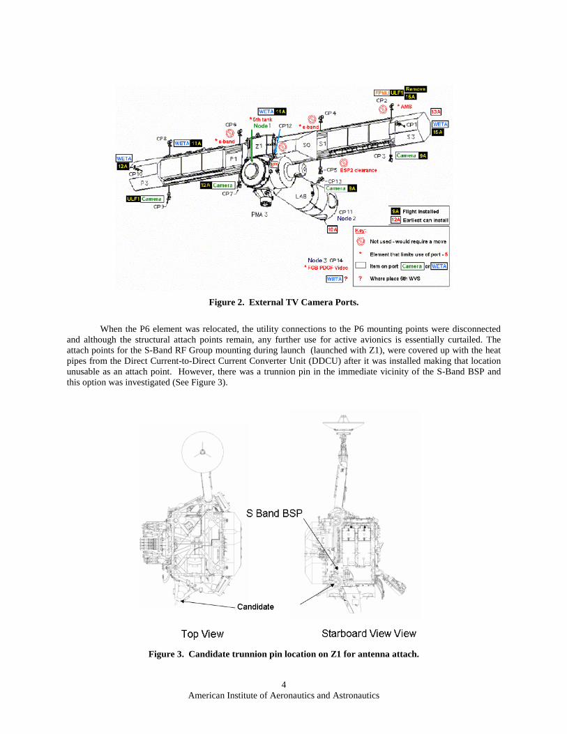
The external camera ports are shown in Figure 2. The only two locations at the time that were unplanned
for use were CP4 and CP6, which are in close proximity to the S-Band system. Using these ports would result in reduced TDRS visibility from the S-Band antennas and were therefore considered to be undesirable candidates. Mounting ORUs within the structure of the truss was considered, but the truss is covered by a shroud for thermal conditioning. Thus, attachment to these points presented complications that made their use undesirable.
Of the various attach points used by S-Band and Ku-Band hardware currently installed on the ISS, four points had become available after the relocation of P6. The P6 (shorthand for Port segment number 6 from the Middle segment numbered S0) segment was launched early in the ISS assembly sequence to provide solar electric power to the Unites States elements. Prior to its arrival, all power was generated by the Russian Segment solar arrays. Because the ISS was built from the center section out, a short truss segment called Z1 was added to the Zenith surface of the S0 segment. The purpose of the Z1 segment was to provide structural and electrical connections for the P6 segment to be mounted temporarily until the P5 segment was delivered.
In addition to providing power, the Z1/P6 truss combination served as the temporary attachment location for the USOS command and telemetry communications system, a single S-Band system consisting of a Baseband Signal Processor (BSP), a Transponder and the Radio Frequency Group. The final location of this string of the S-Band communication system was on the P1 truss, and although the P1 segment was installed on the ISS as part of the build up to the P5 segment in 2002, the S-Band communications coverage from the top of the P6 element was superior. Thus, the string remained on the Z1/P6 elements until the P6 truss was relocated to its final location. Since S-Band RF group’s operational location was on P6, and due to coaxial cable length constraints, the operational location for the S-Band Transponder, which is the S-Band Modem, was also on P6.
4 American Institute of Aeronautics and Astronautics
Figure 2. External TV Camera Ports.
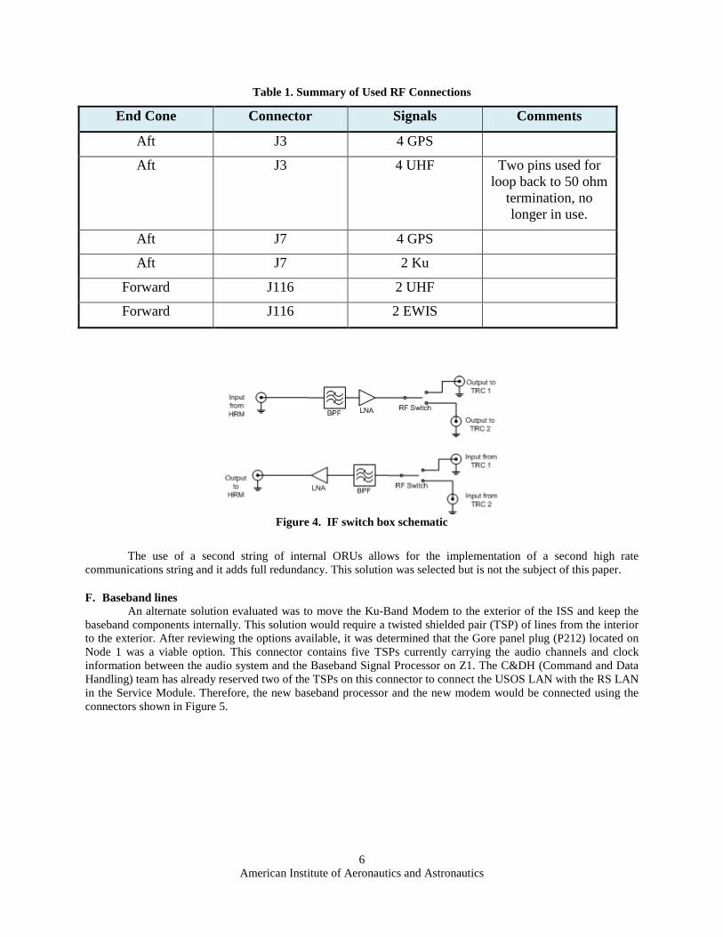
When the P6 element was relocated, the utility connections to the P6 mounting points were disconnected and although the structural attach points remain, any further use for active avionics is essentially curtailed. The attach points for the S-Band RF Group mounting during launch (launched with Z1), were covered up with the heat pipes from the Direct Current-to-Direct Current Converter Unit (DDCU) after it was installed making that location unusable as an attach point. However, there was a trunnion pin in the immediate vicinity of the S-Band BSP and this option was investigated (See Figure 3).
Figure 3. Candidate trunnion pin location on Z1 for antenna attach.

5 American Institute of Aeronautics and Astronautics
C. Control data bus Since the new Ku-Band Antenna Group will be controlled the same way as the existing Ku-Band Antenna
Group, the equipment must be attached to the Communications and Tracking (C&T) bus from the Command and Control MDMs. This bus is externally limited to the external video switches and the existing S-Band and Ku-Band mounting points. The S-Band mounting locations include the previously mentioned interim S-Band mount on the Z1 truss which was available for use. Use of other buses, such as the payload bus, was considered, but control at the payload attach points would require 1553 control to be distributed by the Payload MDM in the US Lab. Since these locations attach to lower tier MDMs, the control from the Command and Control MDMs would need to pass through the lower tier units. This would require additional software and was considered to be unacceptable as a solution.
D. Power distribution External power distribution is provided from the Remote Power Control Modules which distribute power to
existing ORU locations and payload attach points. In addition to the payload attach points, power could be provided from any of the camera ports or from the temporary S-Band BSP location on Z1. After the removal of P6 from Z1, there were available power ports for use. During a review of the power connectivity, a conscious effort was made to select a different power domain from the existing Ku-Band Antenna Group. The power domains for the ISS are separated so that if a failure occurs on one domain, the second will keep operating. This is primarily used with critical systems to provide two failure tolerance. A review of the external power ports in the Power Architecture notebook yielded 34 ports with notes indicating they might be available. Twelve of these ports are associated with external camera group locations while ten have assignments for cameras, Wireless Video System (WVS) External Transceiver Assemblies (WETAs) or the Floating Potential Measurement Unit (FPMU). Eight ports are associated with external lighting locations, seven are identified as EVA plug locations, one is assigned to the Interim Control Module and two are listed as power connections for spares storage.
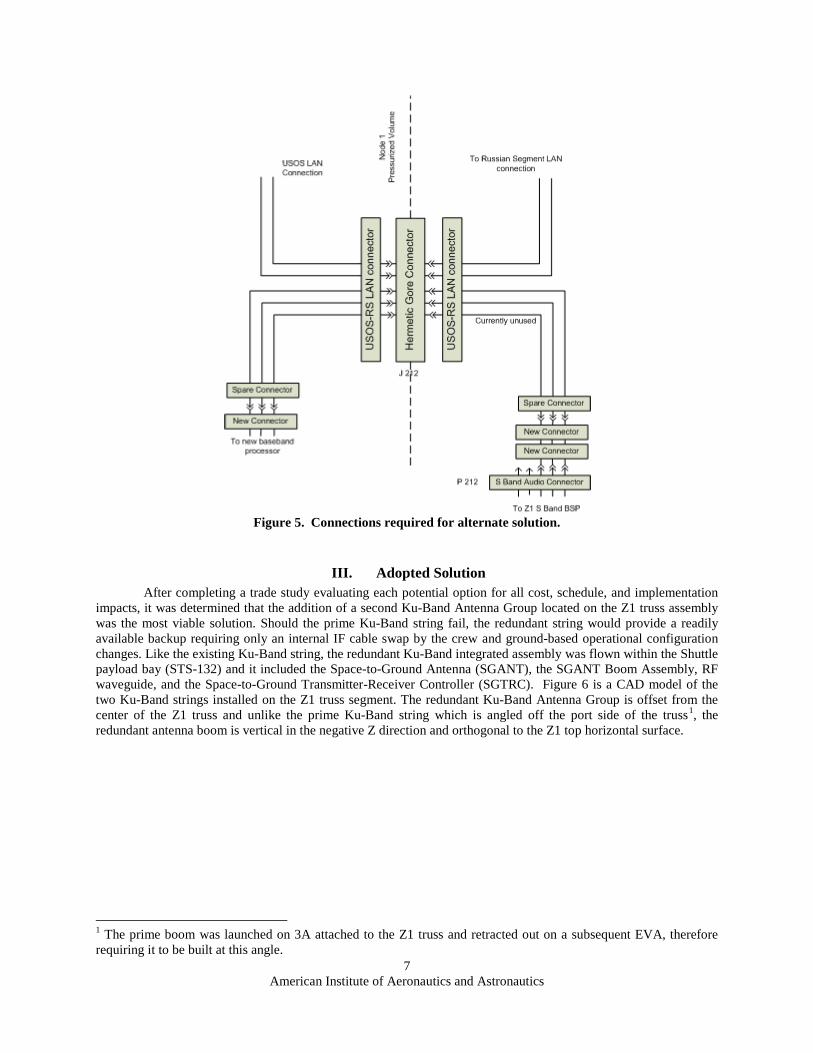
E. Transmission lines There are a total of twenty-four coaxial penetrations on the ISS distributed in three connectors. Two are
used for the existing Ku-Band Intermediate Frequency forward and return signals. Four are used for the Space to Space Communications System and eight are used for the GPS antennas. Two were used to terminate the unused truss antenna signals prior to the delivery of the P1 truss element and are currently unused. Finally, two are used by the External Wireless Instrumentation System (EWIS). A summary of the used contacts is provided in Table 1. With ten unassigned and two more 50 ohm terminated transmission lines available, the use of an internal or external RF switch/diplexer or the addition of a second Ku-Band string became a viable option. Both options assumed the baseband components would be located within the US Lab.
An RF switch on the Ku-Band communications paths could be used to select a destination RF Group. The internal ORUs could continue to perform the baseband processing and create the modulated intermediate frequency signal. This, however, would still leave a single failure point within the switch. It might also be necessary to add additional band pass filtering and a subsequent low noise amplifier (LNA) to restore signal levels (Figure 4). Using a switch like the one shown in Figure 4, the IF signals could be routed to and from the active Antenna Group. Because the solution selected uses a modem internal to the ISS, placing the switch internally allows for Intravehicular Activity (IVA) maintenance; however, it also uses two of the remaining available termini and requires more external cable installation.
American Institute of Aeronautics and Astronautics
6
Table 1. Summary of Used RF Connections
End Cone Connector Signals Comments
Aft J3 4 GPS
Aft J3 4 UHF Two pins used for loop back to 50 ohm
termination, no longer in use.
Aft J7 4 GPS
Aft J7 2 Ku
Forward J116 2 UHF
Forward J116 2 EWIS
Figure 4. IF switch box schematic
The use of a second string of internal ORUs allows for the implementation of a second high rate communications string and it adds full redundancy. This solution was selected but is not the subject of this paper.
F. Baseband lines An alternate solution evaluated was to move the Ku-Band Modem to the exterior of the ISS and keep the
baseband components internally. This solution would require a twisted shielded pair (TSP) of lines from the interior to the exterior. After reviewing the options available, it was determined that the Gore panel plug (P212) located on Node 1 was a viable option. This connector contains five TSPs currently carrying the audio channels and clock information between the audio system and the Baseband Signal Processor on Z1. The C&DH (Command and Data Handling) team has already reserved two of the TSPs on this connector to connect the USOS LAN with the RS LAN in the Service Module. Therefore, the new baseband processor and the new modem would be connected using the connectors shown in Figure 5.
American Institute of Aeronautics and Astronautics
7
Figure 5. Connections required for alternate solution.
III. Adopted Solution After completing a trade study evaluating each potential option for all cost, schedule, and implementation
impacts, it was determined that the addition of a second Ku-Band Antenna Group located on the Z1 truss assembly was the most viable solution. Should the prime Ku-Band string fail, the redundant string would provide a readily available backup requiring only an internal IF cable swap by the crew and ground-based operational configuration changes. Like the existing Ku-Band string, the redundant Ku-Band integrated assembly was flown within the Shuttle payload bay (STS-132) and it included the Space-to-Ground Antenna (SGANT), the SGANT Boom Assembly, RF waveguide, and the Space-to-Ground Transmitter-Receiver Controller (SGTRC). Figure 6 is a CAD model of the two Ku-Band strings installed on the Z1 truss segment. The redundant Ku-Band Antenna Group is offset from the center of the Z1 truss and unlike the prime Ku-Band string which is angled off the port side of the truss1
1 The prime boom was launched on 3A attached to the Z1 truss and retracted out on a subsequent EVA, therefore requiring it to be built at this angle.
, the redundant antenna boom is vertical in the negative Z direction and orthogonal to the Z1 top horizontal surface.
American Institute of Aeronautics and Astronautics
8
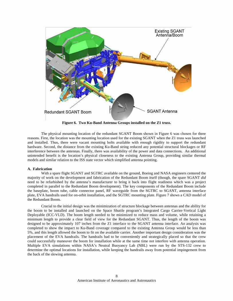
Figure 6. Two Ku-Band Antenna Groups installed on the Z1 truss.
The physical mounting location of the redundant SGANT Boom shown in Figure 6 was chosen for three reasons. First, the location was the mounting location used for the existing SGANT when the Z1 truss was launched and installed. Thus, there were vacant mounting bolts available with enough rigidity to support the redundant hardware. Second, the distance from the existing Ku-Band string reduced any potential structural blockages or RF interference between the antennas. Finally, there was availability of the power and data connections. An additional unintended benefit is the location’s physical closeness to the existing Antenna Group, providing similar thermal models and similar relation to the ISS state vector which simplified antenna pointing.
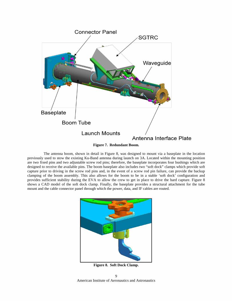
A. Fabrication With a spare flight SGANT and SGTRC available on the ground, Boeing and NASA engineers centered the
majority of work on the development and fabrication of the Redundant Boom itself (though, the spare SGANT did need to be refurbished by the antenna’s manufacturer to bring it back into flight readiness which was a project completed in parallel to the Redundant Boom development). The key components of the Redundant Boom include the baseplate, boom tube, cable connector panel, RF waveguide from the SGTRC to SGANT, antenna interface plate, EVA handrails used for on-orbit installation, and the SGTRC mounting plate. Figure 7 shows a CAD model of the Redundant Boom.
Crucial to the initial design was the minimization of structure blockage between antennas and the ability for the boom to be installed and launched on the Space Shuttle program’s Integrated Cargo Carrier-Vertical Light Deployable (ICC-VLD). The boom length needed to be minimized to reduce mass and volume, while retaining a minimum length to provide a clear field of view for the Redundant SGANT. Thus, the length of the boom was designed to be approximately 107 inches from the Z1 interface to the SGANT antenna interface. An analysis was completed to show the impact to Ku-Band coverage compared to the existing Antenna Group would be less than 5%, and this length allowed the boom to fit on the available carrier. Another important design consideration was the placement of the EVA handrails. The handrails had to be conveniently and strategically placed so that the crew could successfully maneuver the boom for installation while at the same time not interfere with antenna operation. Multiple EVA simulations within NASA’s Neutral Buoyancy Lab (NBL) were run by the STS-132 crew to determine the optimal locations for installation, while keeping the handrails away from potential impingement from the back of the slewing antenna.
American Institute of Aeronautics and Astronautics
9
Figure 7. Redundant Boom.
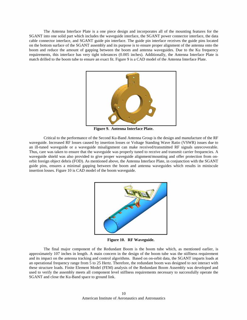
The antenna boom, shown in detail in Figure 8, was designed to mount via a baseplate in the location
previously used to stow the existing Ku-Band antenna during launch on 3A. Located within the mounting position are two fixed pins and two adjustable screw rod pins; therefore, the baseplate incorporates four bushings which are designed to receive the available pins. The boom baseplate also includes two “soft dock” clamps which provide soft capture prior to driving in the screw rod pins and, in the event of a screw rod pin failure, can provide the backup clamping of the boom assembly. This also allows for the boom to be in a stable ‘soft dock’ configuration and provides sufficient stability during the EVA to allow the crew to get in place to drive the hard capture. Figure 8 shows a CAD model of the soft dock clamp. Finally, the baseplate provides a structural attachment for the tube mount and the cable connector panel through which the power, data, and IF cables are routed.
Figure 8. Soft Dock Clamp.
American Institute of Aeronautics and Astronautics
10
The Antenna Interface Plate is a one piece design and incorporates all of the mounting features for the SGANT into one solid part which includes the waveguide interface, the SGANT power connector interface, the data cable connector interface, and SGANT guide pin interface. The guide pin interface receives the guide pins located on the bottom surface of the SGANT assembly and its purpose is to ensure proper alignment of the antenna onto the boom and reduce the amount of gapping between the boom and antenna waveguides. Due to the Ku frequency requirements, this interface has very tight tolerances (0.005 inches). Additionally, the Antenna Interface Plate is match drilled to the boom tube to ensure an exact fit. Figure 9 is a CAD model of the Antenna Interface Plate.
Figure 9. Antenna Interface Plate.
Critical to the performance of the Second Ku-Band Antenna Group is the design and manufacture of the RF
waveguide. Increased RF losses caused by insertion losses or Voltage Standing Wave Ratio (VSWR) issues due to an ill-tuned waveguide or a waveguide misalignment can make received/transmitted RF signals unrecoverable. Thus, care was taken to ensure that the waveguide was properly tuned to receive and transmit carrier frequencies. A waveguide shield was also provided to give proper waveguide alignment/mounting and offer protection from on-orbit foreign object debris (FOD). As mentioned above, the Antenna Interface Plate, in conjunction with the SGANT guide pins, ensures a minimal gapping between the boom and antenna waveguides which results in miniscule insertion losses. Figure 10 is CAD model of the boom waveguide.
Figure 10. RF Waveguide.
The final major component of the Redundant Boom is the boom tube which, as mentioned earlier, is
approximately 107 inches in length. A main concern in the design of the boom tube was the stiffness requirement and its impact on the antenna tracking and control algorithms. Based on on-orbit data, the SGANT imparts loads at an operational frequency range from 5 to 25 Hertz. Therefore, the redundant boom was designed to not interact with these structure loads. Finite Element Model (FEM) analysis of the Redundant Boom Assembly was developed and used to verify the assembly meets all component level stiffness requirements necessary to successfully operate the SGANT and close the Ku-Band space to ground link.

American Institute of Aeronautics and Astronautics
11
B. Redundant Boom Assembly Integration and Testing The integration of the Redundant Boom Assembly occurred at the Boeing Houston Product Support Center
(HPSC), Houston, Texas. Each component was individually inspected by Boeing engineers and approved by Boeing Quality Assurance (QA) before the component was installed onto the assembly. Per the appropriate NASA processes, Boeing QA verified that the critical characteristics of the design were identified and that they conformed to all engineering specifications. Additionally, QA ensured that all tests performed on the Boom Assembly demonstrated that the program, contract, drawing, and specification requirements were met and that the tests were performed in accordance with approved procedures and properly documented.
The Redundant Boom assembly was put through a battery of tests to verify its performance requirements. In the spirit of brevity, only a few keys tests are mentioned in this paper. First, testing of each individual power, data, and RF cable was performed. The cable tests included continuity, insulation resistance, and insertion loss tests. Additional tests were performed on the coaxial cables to determine the VSWR and phase linearity for each RF cable. Next, the Boom Assembly with a SGTRC mass simulator installed was put through a thermal cycle and vibration testing. Each thermal cycle test was performed for a minimum of eight cycles with the temperature range of 10° F above and below the predicted range. During the thermal sweep, the launch restraint bolts and contingency EVA bolts were tested for functionality. The vibration tests, conducted at Johnson Space Center, were performed at the maximum predicted flight levels for one minute in each of the three orthogonal axes. Following each vibration test, a functional test of the waveguide and cables as well as a visual inspection of the Boom Assembly was performed.
Following the thermal and vibration testing, the SGTRC flight unit was installed onto the SGTRC plate and a fit check was performed. Since the launch configuration of the Redundant Boom assembly included the SGTRC plus a multilayer insulation (MLI) cover, the SGTRC EVA bolts were tightened to their specified torque requirement for both launch and on-orbit installation. Figure 11 is a picture of the flight SGTRC plus MLI cover installed onto the Redundant Boom. Next, a fit check was performed at the HPSC to ensure no gapping existed between the SGANT interface plate and a dummy, flight-equivalent Antenna Group Interface Tube (AGIT), which is the bottom component of the SGANT that is bolted to the boom. Any gaps or misalignments in the waveguide would increase the insertion losses seen on both the forward and return links; thus, it was important to ensure a precise fit. First, a visual inspection was performed to verify a “good” fit between the two components and was followed by physically measuring the gap. The resulting measurements confirmed the gap and alignment at the waveguide interface was within the designed tolerance, thus introducing minimal insertion losses.
Using the flight SGTRC, the dummy AGIT, and standard RF testing equipment, Boeing and NASA engineers performed waveguide insertion loss tests and determined the VSWWSR using the forward and return link carrier frequencies. The tests provided good figures of merit in the absence of the flight SGANT, which was being refurbished for launch. The measured insertion losses and VWSRs were well within the required tolerances to close the RF link. With the completion of the RF test, both NASA and Boeing C&T teams were in concurrence that the Redundant Boom was ready to launch for on-orbit operations.
As a final step, the dummy AGIT was removed and the Redundant Boom was delivered to Kennedy Space Center for processing and integration onto the ICC-VLD. Additionally, the flight SGANT was delivered by the antenna manufacturer to KSC and integrated into its Flight Support Equipment (FSE) for mounting onto the ICC-VLD. Here the EVA crew tasked to install the hardware completed a final walk through and inspection and posed hardware related questions to engineering.
American Institute of Aeronautics and Astronautics
12
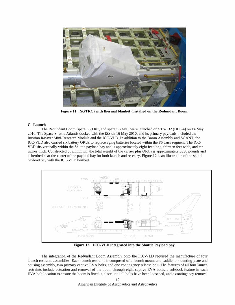
Figure 11. SGTRC (with thermal blanket) installed on the Redundant Boom.
C. Launch The Redundant Boom, spare SGTRC, and spare SGANT were launched on STS-132 (ULF-4) on 14 May
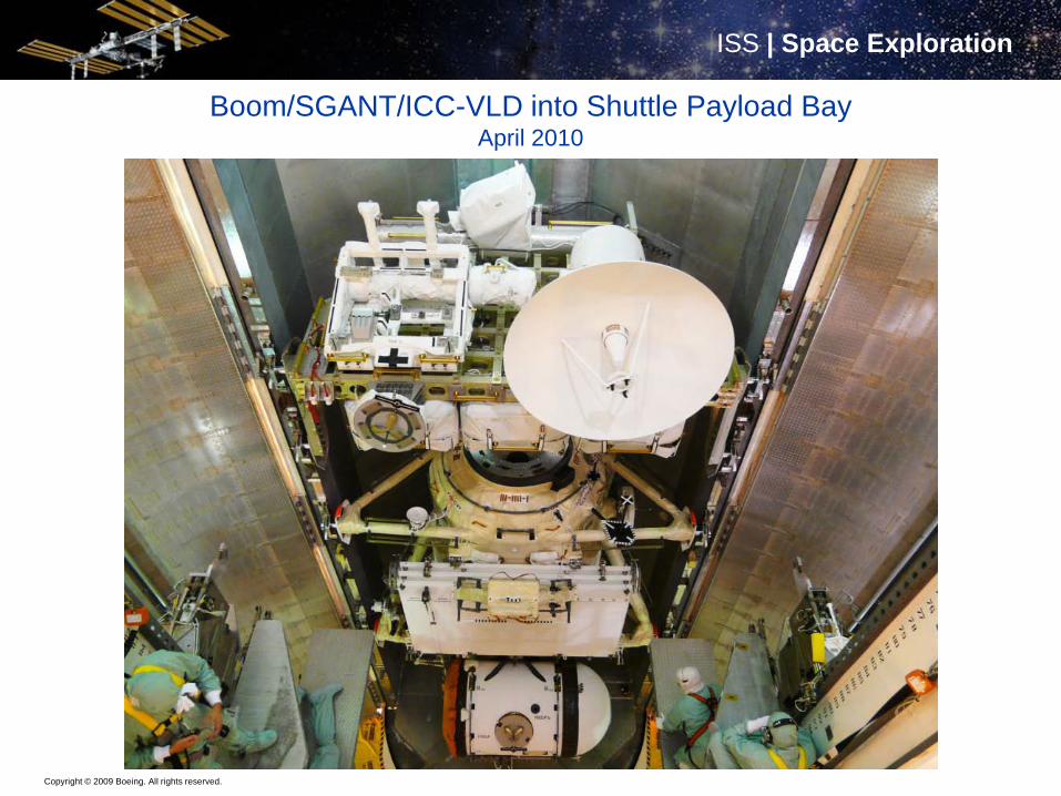
2010. The Space Shuttle Atlantis docked with the ISS on 16 May 2010, and its primary payloads included the Russian Rassvet Mini-Research Module and the ICC-VLD. In addition to the Boom Assembly and SGANT, the ICC-VLD also carried six battery ORUs to replace aging batteries located within the P6 truss segment. The ICC-VLD sits vertically within the Shuttle payload bay and is approximately eight feet long, thirteen feet wide, and ten inches thick. Constructed of aluminum, the total weight of the carrier plus ORUs is approximately 8330 pounds and is berthed near the center of the payload bay for both launch and re-entry. Figure 12 is an illustration of the shuttle payload bay with the ICC-VLD berthed.
Figure 12. ICC-VLD integrated into the Shuttle Payload bay.
The integration of the Redundant Boom Assembly onto the ICC-VLD required the manufacture of four launch restraint assemblies. Each launch restraint is composed of a launch mount and saddle, a mounting plate and housing assembly, two primary captive EVA bolts, and one contingency release bolt. The features of all four launch restraints include actuation and removal of the boom through eight captive EVA bolts, a softdock feature in each EVA bolt location to ensure the boom is fixed in place until all bolts have been loosened, and a contingency removal
American Institute of Aeronautics and Astronautics
13
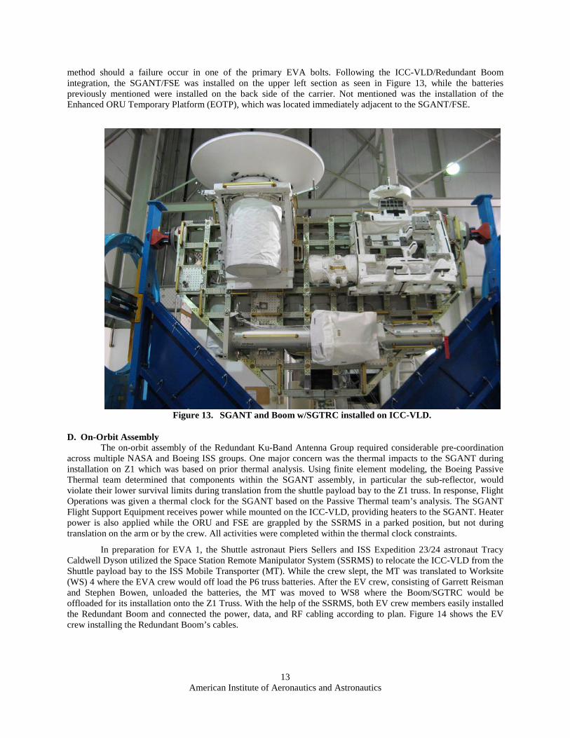
method should a failure occur in one of the primary EVA bolts. Following the ICC-VLD/Redundant Boom integration, the SGANT/FSE was installed on the upper left section as seen in Figure 13, while the batteries previously mentioned were installed on the back side of the carrier. Not mentioned was the installation of the Enhanced ORU Temporary Platform (EOTP), which was located immediately adjacent to the SGANT/FSE.
Figure 13. SGANT and Boom w/SGTRC installed on ICC-VLD.
D. On-Orbit Assembly The on-orbit assembly of the Redundant Ku-Band Antenna Group required considerable pre-coordination
across multiple NASA and Boeing ISS groups. One major concern was the thermal impacts to the SGANT during installation on Z1 which was based on prior thermal analysis. Using finite element modeling, the Boeing Passive Thermal team determined that components within the SGANT assembly, in particular the sub-reflector, would violate their lower survival limits during translation from the shuttle payload bay to the Z1 truss. In response, Flight Operations was given a thermal clock for the SGANT based on the Passive Thermal team’s analysis. The SGANT Flight Support Equipment receives power while mounted on the ICC-VLD, providing heaters to the SGANT. Heater power is also applied while the ORU and FSE are grappled by the SSRMS in a parked position, but not during translation on the arm or by the crew. All activities were completed within the thermal clock constraints.
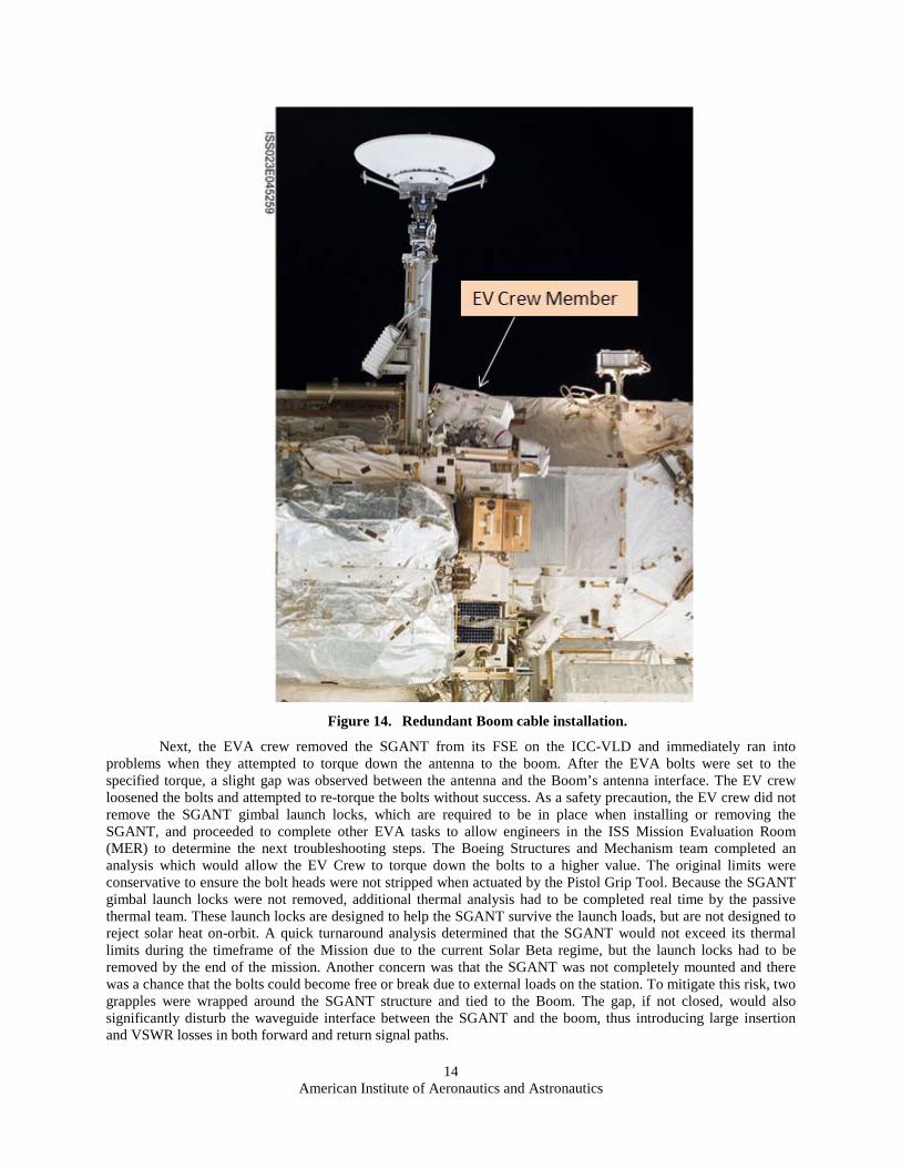
In preparation for EVA 1, the Shuttle astronaut Piers Sellers and ISS Expedition 23/24 astronaut Tracy Caldwell Dyson utilized the Space Station Remote Manipulator System (SSRMS) to relocate the ICC-VLD from the Shuttle payload bay to the ISS Mobile Transporter (MT). While the crew slept, the MT was translated to Worksite (WS) 4 where the EVA crew would off load the P6 truss batteries. After the EV crew, consisting of Garrett Reisman and Stephen Bowen, unloaded the batteries, the MT was moved to WS8 where the Boom/SGTRC would be offloaded for its installation onto the Z1 Truss. With the help of the SSRMS, both EV crew members easily installed the Redundant Boom and connected the power, data, and RF cabling according to plan. Figure 14 shows the EV crew installing the Redundant Boom’s cables.
American Institute of Aeronautics and Astronautics
14
Figure 14. Redundant Boom cable installation.
Next, the EVA crew removed the SGANT from its FSE on the ICC-VLD and immediately ran into problems when they attempted to torque down the antenna to the boom. After the EVA bolts were set to the specified torque, a slight gap was observed between the antenna and the Boom’s antenna interface. The EV crew loosened the bolts and attempted to re-torque the bolts without success. As a safety precaution, the EV crew did not remove the SGANT gimbal launch locks, which are required to be in place when installing or removing the SGANT, and proceeded to complete other EVA tasks to allow engineers in the ISS Mission Evaluation Room (MER) to determine the next troubleshooting steps. The Boeing Structures and Mechanism team completed an analysis which would allow the EV Crew to torque down the bolts to a higher value. The original limits were conservative to ensure the bolt heads were not stripped when actuated by the Pistol Grip Tool. Because the SGANT gimbal launch locks were not removed, additional thermal analysis had to be completed real time by the passive thermal team. These launch locks are designed to help the SGANT survive the launch loads, but are not designed to reject solar heat on-orbit. A quick turnaround analysis determined that the SGANT would not exceed its thermal limits during the timeframe of the Mission due to the current Solar Beta regime, but the launch locks had to be removed by the end of the mission. Another concern was that the SGANT was not completely mounted and there was a chance that the bolts could become free or break due to external loads on the station. To mitigate this risk, two grapples were wrapped around the SGANT structure and tied to the Boom. The gap, if not closed, would also significantly disturb the waveguide interface between the SGANT and the boom, thus introducing large insertion and VSWR losses in both forward and return signal paths.
American Institute of Aeronautics and Astronautics
15
During EVA 2 (Flight Day 6), the EVA crew re-tightened the SGANT EVA bolts using a higher torque setting and subsequently closed the gap left after EVA 1. Astronaut Michael Good performed a “wiggle” test to verify that the gap had been closed and, upon successful completion of the test, he and astronaut Stephen Bowen removed the grapple hooks, the gimbal launch locks, the SGTRC MLI cover, and installed the SGANT Tracking Modulator Driver Thermal Heat Shield. After the EVA crew translated away from the Z1, ISS flight controllers applied heater power to the SGTRC and operational/heater power to the SGANT. After completion of the Redundant Antenna Group, the SGANT and SGTRC were officially given the names SGANT-2 and SGTRC-2 to differentiate them from the original Ku-Band string.
E. Activation Official activation and checkout of the new antenna group was not planned to occur until after STS-132
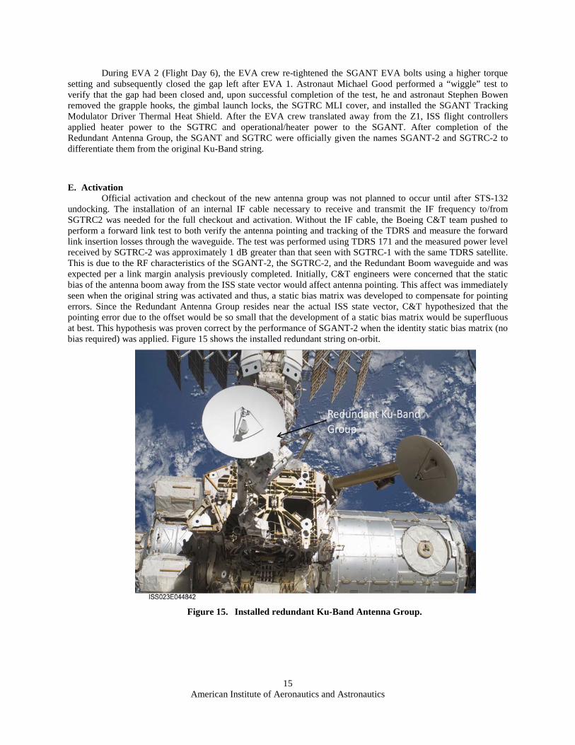
undocking. The installation of an internal IF cable necessary to receive and transmit the IF frequency to/from SGTRC2 was needed for the full checkout and activation. Without the IF cable, the Boeing C&T team pushed to perform a forward link test to both verify the antenna pointing and tracking of the TDRS and measure the forward link insertion losses through the waveguide. The test was performed using TDRS 171 and the measured power level received by SGTRC-2 was approximately 1 dB greater than that seen with SGTRC-1 with the same TDRS satellite. This is due to the RF characteristics of the SGANT-2, the SGTRC-2, and the Redundant Boom waveguide and was expected per a link margin analysis previously completed. Initially, C&T engineers were concerned that the static bias of the antenna boom away from the ISS state vector would affect antenna pointing. This affect was immediately seen when the original string was activated and thus, a static bias matrix was developed to compensate for pointing errors. Since the Redundant Antenna Group resides near the actual ISS state vector, C&T hypothesized that the pointing error due to the offset would be so small that the development of a static bias matrix would be superfluous at best. This hypothesis was proven correct by the performance of SGANT-2 when the identity static bias matrix (no bias required) was applied. Figure 15 shows the installed redundant string on-orbit.
Figure 15. Installed redundant Ku-Band Antenna Group.
American Institute of Aeronautics and Astronautics
16
IV. Conclusion The International Space Station provides opportunities for major upgrades beyond the original growth
plans. As a result of the incremental on-orbit build process, there are various structural and electrical interfaces used temporarily during the assembly process which provide suitable connectivity for evolutionary upgrades. During this activity, solutions were found that closely aligned with the original interface concepts as well as hybrid concepts. By minimizing structural differences between the original and the redundant antenna groups, the EVA assembly was able to utilize many of the same steps and tools that were used in the original Antenna Group assembly. Similarly, by minimizing the performance differences, the same check out process and, consequently, the expected performance aligned with the original Antenna Group. Future upgrades will likely add new performance and, therefore, will not have some of the benefits of which this upgrade took advantage. However, with careful planning and reuse of existing interfaces coupled with adaptation of techniques used in the original assembly, a variety of enhancements and upgrades are possible.2
2 As of the writing of this paper, the internal IF cables have been routed within the US Lab, and the new
Antenna Group has been fully operational and utilized. The performance is nominal, with positive link margins at the current ISS data rates of 150 Mbps downlink and 3 Mbps uplink. As expected, the positive link margins confirmed previously performed link budget analyses.

American Institute of Aeronautics and Astronautics
17
Acronym List
AGIT Antenna Group Interface Tube BSP Baseband Signal Processor C&DH Command and Data Handling C&T Communications and Tracking DDCU Direct Current-to-Direct Current Converter Unit EVA ExtraVehicular Activity EWIS External Wireless Instrumentation System FPMU Floating Potential Measurement Unit FSE Flight Support Equipment ICC-VLD Integrated Cargo Carrier-Vertical Light Deployable IF Intermediate frequency ISS International Space Station MDM Multiplexer/Demultiplexer MER Mission Evaluation Room MLI multilayer insulation MTBF Mean Time Between Failures NBL Neutral Buoyancy Lab ORU Orbital Replaceable Unit RPCM Remote Power Controller Module SGANT Space-to-Ground Antenna SGTRC Space-to-Ground Transmitter/Receiver Controller SIGI Space Integrated Global Positioning System/ Inertial Navigation System TDRSS Tracking and Data Relay Satellite System TSP Twisted Shielded Pair UHF Ultra High Frequency USOS United States On-orbit Segment VSWR Voltage Standing Wave Ratio WETA Wireless Video System (WVS) External Transceiver Assembly
BOEING is a trademark of Boeing Management Company.Copyright © 2009 Boeing. All rights reserved.
Adding a Second Ku-Band Antenna to the International Space Station
Charles Dusold (Boeing)Sundeep Kwatra (NASA)Corey Thacker (Boeing)
Copyright © 2009 Boeing. All rights reserved.
ISS | Space ExplorationISS | Space Exploration
Agenda
• Background• Overview of Analysis and Conceptual Design• Adopted Solution• On-Orbit Assembly• Operation• Conclusion
Copyright © 2009 Boeing. All rights reserved.
ISS | Space ExplorationISS | Space Exploration
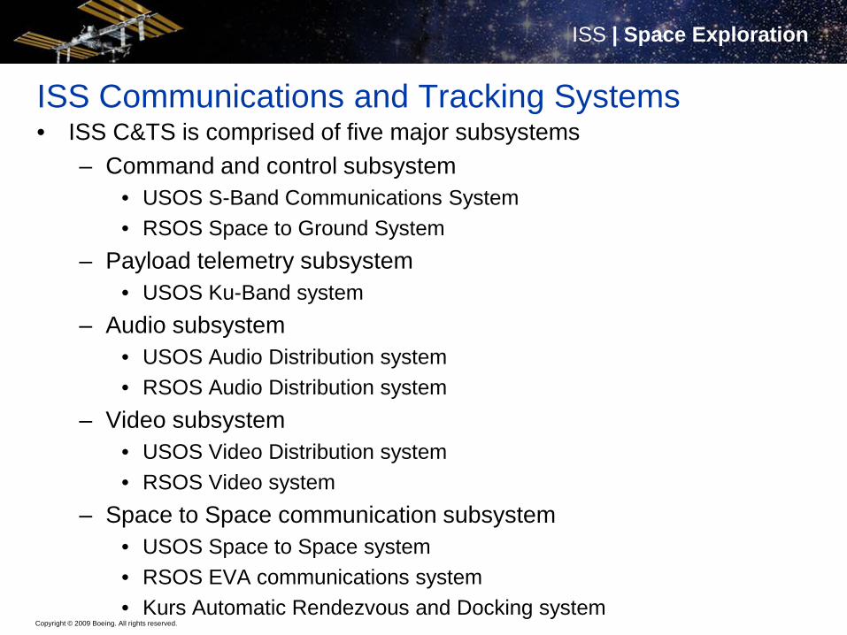
ISS Communications and Tracking Systems• ISS C&TS is comprised of five major subsystems
– Command and control subsystem• USOS S-Band Communications System• RSOS Space to Ground System
– Payload telemetry subsystem• USOS Ku-Band system
– Audio subsystem• USOS Audio Distribution system• RSOS Audio Distribution system
– Video subsystem• USOS Video Distribution system• RSOS Video system
– Space to Space communication subsystem• USOS Space to Space system• RSOS EVA communications system• Kurs Automatic Rendezvous and Docking system
Copyright © 2009 Boeing. All rights reserved.
ISS | Space ExplorationISS | Space Exploration
Genesis of upgrade
• In 2007 NASA initiated an effort to determine the required number of on-orbit spare Orbital Replaceable Units (ORU) required for the expected life of the ISS– Analysis of the Ku-Band Antenna and Space to Ground
Transmitter/Receiver/Controller (SGTRC) Mean Time Between Failures indicated a need for two spare units to be kept on the ISS
– Initial proposal was to deliver two of each unit to the ISS for storage on the exterior truss of the ISS on pallets with power for thermal conditioning and potentially MIL-1553 interfaces for periodic check out
– Boeing proposed a study to identify options available, using residual interfaces from incremental assembly to provide a operational location for at least one of the spare ORU strings
Copyright © 2009 Boeing. All rights reserved.
ISS | Space ExplorationISS | Space Exploration
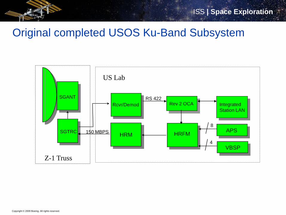
Original completed USOS Ku-Band Subsystem
SGANT
SGTRC HRM HRFM
VBSP
Rcvr/Demod
4
150 MBPS APS8
Z-1 Truss
US Lab
Rev 2 OCARS 422
IntegratedStation LAN
Copyright © 2009 Boeing. All rights reserved.
ISS | Space ExplorationISS | Space Exploration
Survey of residual interfaces suitable for use
• The early ISS configuration placed one of the solar array assemblies in a temporary location in the center of the configuration– Assembly of the ISS started with the center core elements and
proceeded outward to port and starboard with truss segments• To complete the port side of the ISS the solar array was relocated
from the temporary location in the center of the configuration to the end of the port truss– The Z1 and P6 elements containing the solar arrays also
contained one string of the USOS S-Band system• These components were relocated to another location when P6 was
relocated• Power and data connections to the USOS S-Band system were
originally intended to remain unused after relocation
Copyright © 2009 Boeing. All rights reserved.
ISS | Space ExplorationISS | Space Exploration
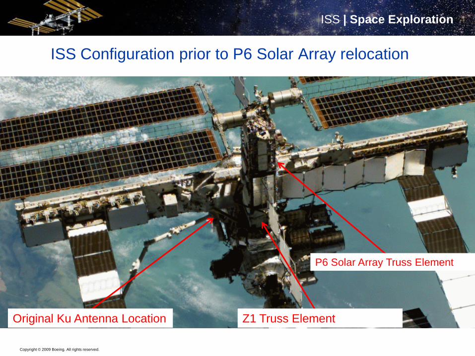
ISS Configuration prior to P6 Solar Array relocation
Original Ku Antenna Location Z1 Truss Element
P6 Solar Array Truss Element
Copyright © 2009 Boeing. All rights reserved.
ISS | Space ExplorationISS | Space Exploration
Early conceptual design• Initial concept was based on use of the residual power and MIL-1553
interfaces no longer in use after relocation of the USOS S-Band system– Three of each interface available after removal of three USOS S-
Band ORUs, only two required for USOS Ku-Band ORUs• A new antenna boom would need to be fabricated to accommodate the
SGANT antenna, SGTRC, new interconnect cabling and waveguide• The trunnion pins used to secure the elements were the mechanically
stiffest attach points available on the Z1 element– The location of one trunnion pin opposite the existing USOS Ku-
Band antenna and SGTRC appeared highly desirable for the new antenna mast
– A Universal Trunnion Attach System developed for payload use could provide a means of structurally securing the new hardware to the Z1 truss, pending a structural analysis
Copyright © 2009 Boeing. All rights reserved.
ISS | Space ExplorationISS | Space Exploration
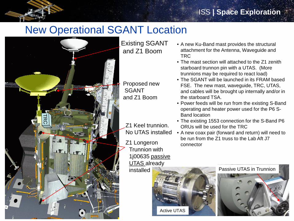
9
New Operational SGANT Location• A new Ku-Band mast provides the structural
attachment for the Antenna, Waveguide and TRC
• The mast section will attached to the Z1 zenith starboard trunnon pin with a UTAS. (More trunnions may be required to react load)
• The SGANT will be launched in its FRAM based FSE. The new mast, waveguide, TRC, UTAS, and cables will be brought up internally and/or in the starboard TSA.
• Power feeds will be run from the existing S-Band operating and heater power used for the P6 S-Band location
• The existing 1553 connection for the S-Band P6 ORUs will be used for the TRC
• A new coax pair (forward and return) will need to be run from the Z1 truss to the Lab Aft J7 connector
Proposed newSGANT and Z1 Boom
Existing SGANTand Z1 Boom
Z1 Keel trunnion.No UTAS installed
Passive UTAS in Trunnion
Active UTAS
Z1 LongeronTrunnion with 1j00635 passive UTAS already installed
Copyright © 2009 Boeing. All rights reserved.
ISS | Space ExplorationISS | Space Exploration
EVA factors affecting decision• The ISS crews are trained for replacement of Criticality 1 hardware
that affect crew survival– The USOS Ku-Band system classified as Criticality 3 is not a
candidate for this training– For EVA removal and replacement of other external ORUs
training material and planning can consume several months– Dependence on the USOS Ku-Band system for crew comfort
communications, motion imagery down link, email and other day to day activities resulted in increased emphasis to minimize down time due to failures
– EVA is inherently hazardous and is nominally avoided• The proposed redesign would not require EVA, only a rerouting of
internal connections of the Intermediate Frequency cables is required to bring the second string to full functionality
Copyright © 2009 Boeing. All rights reserved.
ISS | Space ExplorationISS | Space Exploration
Design maturation• Upon reward of an upgrade contract the structural attach methods
and location were revisited including a trade study to determine that the conceptual design had the optimum attach interface– Attach point provided structural integrity to meet requirements– Proximity to available power, data and control connections– Location optimal for communication coverage
• Trade study complete to determine Boom length – Chosen maximize coverage and not cause RF interference from
existing Ku-Band antenna– Constraint to fit ICC-VLD Carrier and minimize mass
Copyright © 2009 Boeing. All rights reserved.
ISS | Space ExplorationISS | Space Exploration
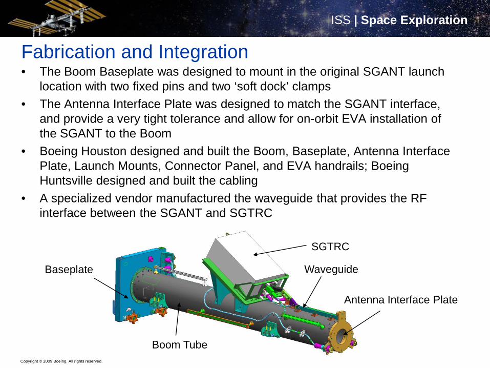
Fabrication and Integration• The Boom Baseplate was designed to mount in the original SGANT launch
location with two fixed pins and two ‘soft dock’ clamps• The Antenna Interface Plate was designed to match the SGANT interface,
and provide a very tight tolerance and allow for on-orbit EVA installation of the SGANT to the Boom
• Boeing Houston designed and built the Boom, Baseplate, Antenna Interface Plate, Launch Mounts, Connector Panel, and EVA handrails; Boeing Huntsville designed and built the cabling
• A specialized vendor manufactured the waveguide that provides the RF interface between the SGANT and SGTRC
SGTRC
Baseplate
Antenna Interface Plate
Waveguide
Boom Tube
Copyright © 2009 Boeing. All rights reserved.
ISS | Space ExplorationISS | Space Exploration
Verification and Test• Integration of the Redundant Boom Assembly occurred at the
Boeing Houston Product Support Center (HPSC)• Verification and Tests Performed at the HPSC included:
– Visual Inspections and Fit Checks– Cable Testing:
• Power And Data Cables– Tests include Continuity, Insulation Resistance, and Insertion
Loss – RF Cables – VSWR, Phase Linearity, and Insertion Loss Tests
– RF Waveguide Test to determine the Forward and Return Link VSWRs and Insertion Loss
• Tests performed at the Johnson Space Center:– Thermal Cycle Tests: 8 cycles per ISS Protoflight requirements– Vibration Testing: Maximum predicted shuttle flight levels for 1
hour in each of the orthogonal axes
Copyright © 2009 Boeing. All rights reserved.
ISS | Space ExplorationISS | Space Exploration
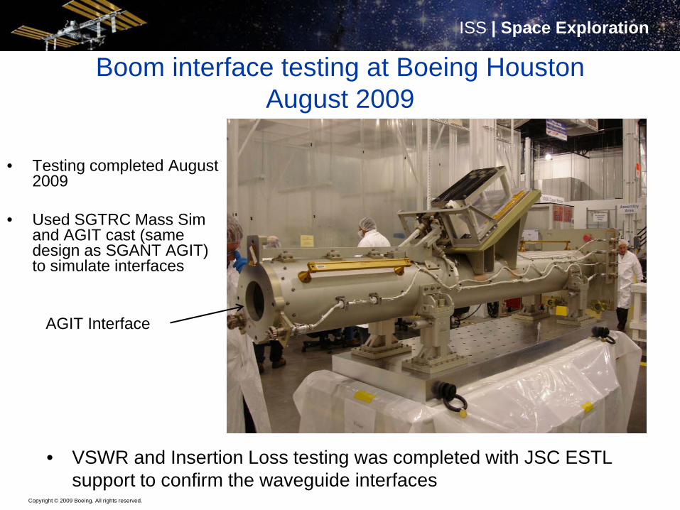
Boom interface testing at Boeing Houston August 2009
• VSWR and Insertion Loss testing was completed with JSC ESTL support to confirm the waveguide interfaces
• Testing completed August2009
• Used SGTRC Mass Sim and AGIT cast (same design as SGANT AGIT) to simulate interfaces
AGIT Interface
Copyright © 2009 Boeing. All rights reserved.
ISS | Space ExplorationISS | Space Exploration
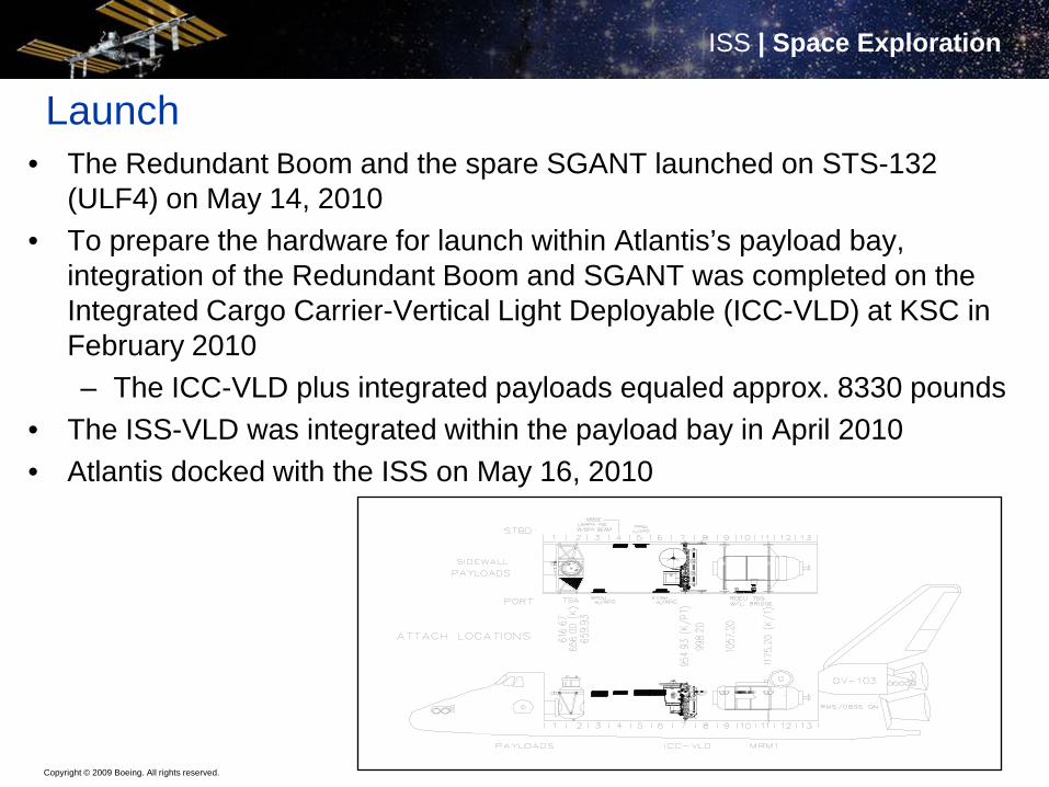
Launch• The Redundant Boom and the spare SGANT launched on STS-132
(ULF4) on May 14, 2010• To prepare the hardware for launch within Atlantis’s payload bay,
integration of the Redundant Boom and SGANT was completed on the Integrated Cargo Carrier-Vertical Light Deployable (ICC-VLD) at KSC in February 2010– The ICC-VLD plus integrated payloads equaled approx. 8330 pounds
• The ISS-VLD was integrated within the payload bay in April 2010• Atlantis docked with the ISS on May 16, 2010
Copyright © 2009 Boeing. All rights reserved.
ISS | Space ExplorationISS | Space Exploration
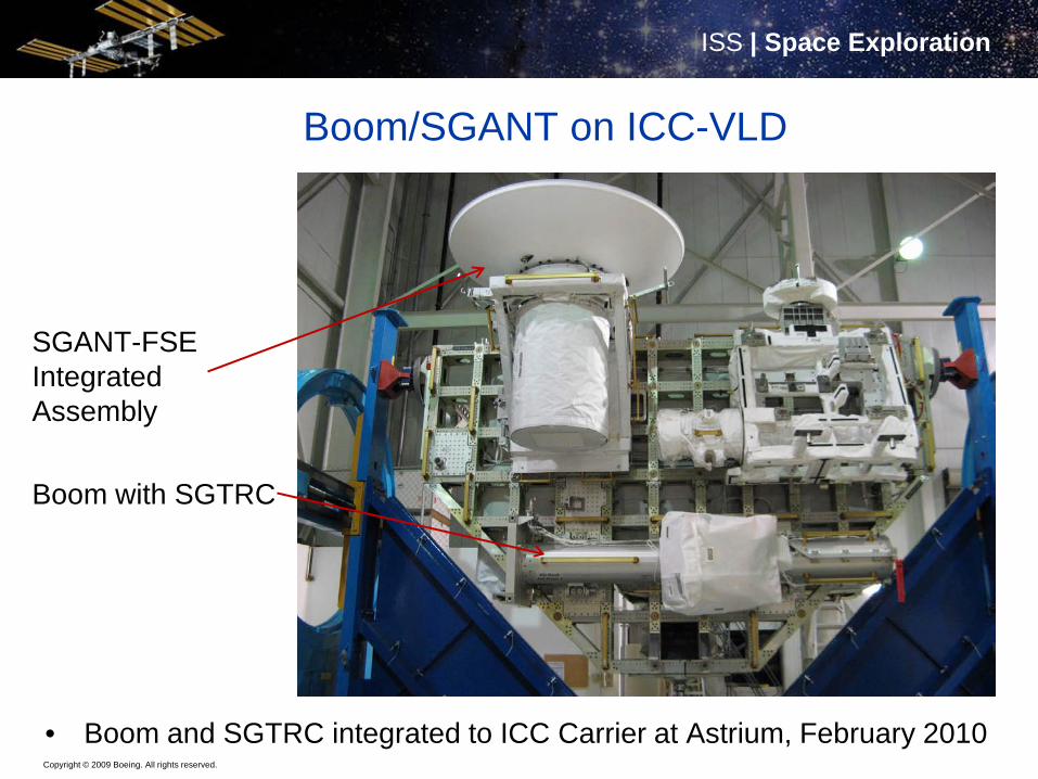
Boom/SGANT on ICC-VLD
• Boom and SGTRC integrated to ICC Carrier at Astrium, February 2010
SGANT-FSE IntegratedAssembly
Boom with SGTRC
Copyright © 2009 Boeing. All rights reserved.
ISS | Space ExplorationISS | Space Exploration
Boom/SGANT/ICC-VLD into Shuttle Payload BayApril 2010
Copyright © 2009 Boeing. All rights reserved.
ISS | Space ExplorationISS | Space Exploration
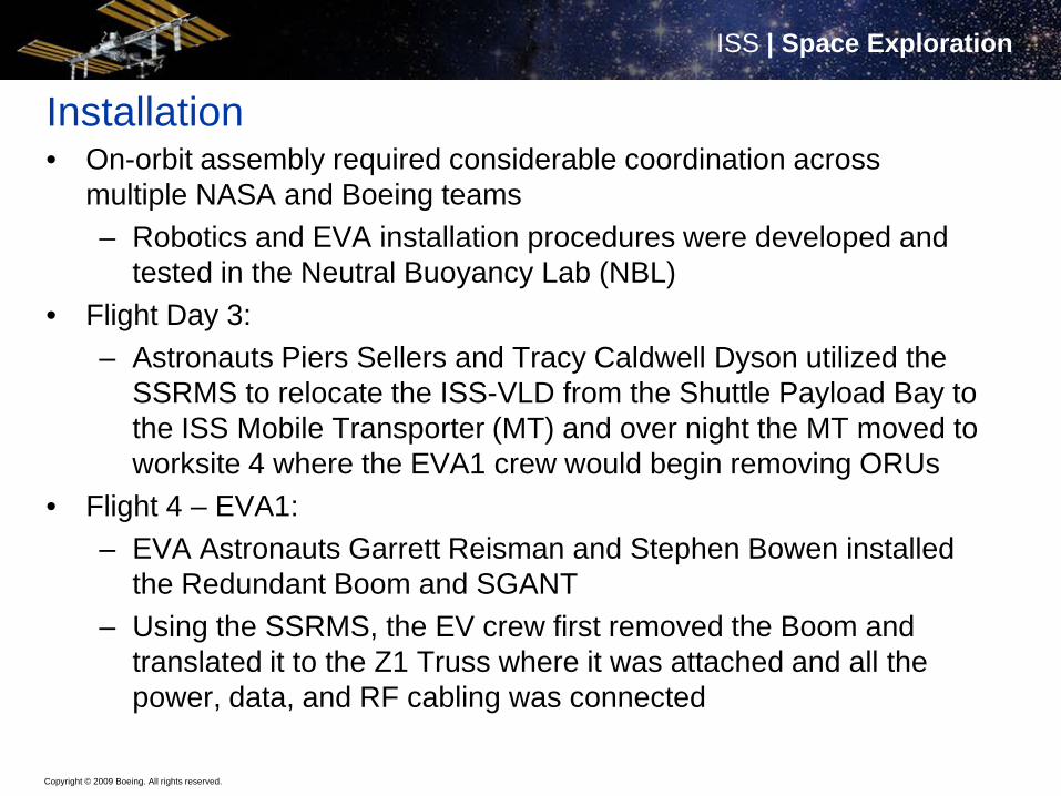
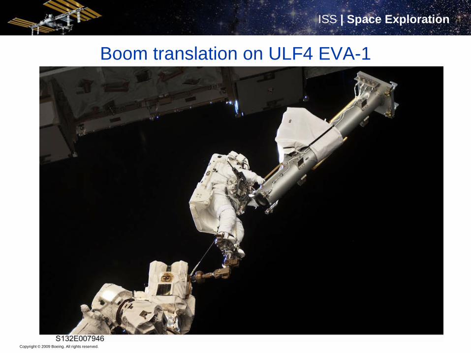
Installation• On-orbit assembly required considerable coordination across
multiple NASA and Boeing teams– Robotics and EVA installation procedures were developed and
tested in the Neutral Buoyancy Lab (NBL) • Flight Day 3:
– Astronauts Piers Sellers and Tracy Caldwell Dyson utilized the SSRMS to relocate the ISS-VLD from the Shuttle Payload Bay to the ISS Mobile Transporter (MT) and over night the MT moved to worksite 4 where the EVA1 crew would begin removing ORUs
• Flight 4 – EVA1:– EVA Astronauts Garrett Reisman and Stephen Bowen installed
the Redundant Boom and SGANT– Using the SSRMS, the EV crew first removed the Boom and
translated it to the Z1 Truss where it was attached and all the power, data, and RF cabling was connected
Copyright © 2009 Boeing. All rights reserved.
ISS | Space ExplorationISS | Space Exploration
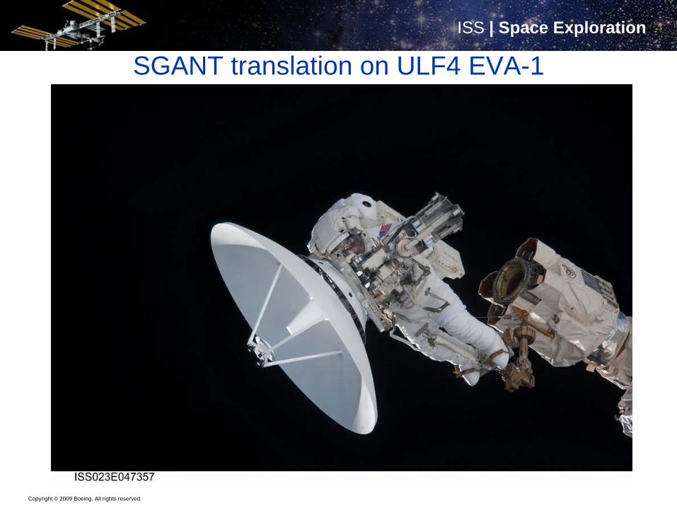
Installation, continued• Flight Day 4 – EVA1:
– Following the installation of the Boom, the SSRMS translated the EV crewmember back to the MT where SGANT was removed from its Flight Support Equipment (FSE) on the ICC-VLD
– After translation back to the Z1 truss, the SGANT was installed onto the Boom, but the crew unable to properly torque the EVA bolts and a slight gap visible at the Boom/SGANT interface
• Any gap at this interface would significantly increase the VSWR in both the forward and return signal paths
– The EV crew attempted to loosen and re-torque the bolts using the same torque settings on the Pistol Grip Tool without success
• The Flight Director recommended to the crew to move on to other scheduled tasks and, as a precaution the gimbal launch locks were not removed from the SGANT to provide added rigidity, and a tether was installed as a secondary safing mechanism
Copyright © 2009 Boeing. All rights reserved.
ISS | Space ExplorationISS | Space Exploration
Installation, continued• Flight Days 4 and 5:
– Engineers within the ISS Mission Evaluation Room quickly worked to determine troubleshooting procedures
– Boeing Passive Thermal Team (PTCS):• PTCS ran finite element models of the SGANT at the current Solar
Beta Angles and determined that the SGANT thermal limits would not be violated with the gimbal launch locks installed
– Note: The launch locks are designed to help the SGANT survive the launch loads only and are not intended to remain installed on-orbit
– Boeing Structures and Mechanisms (S&M): • S&M completed an analysis that determined a higher torque setting
could be used on the Pistol Grip Tool without stripping the EVA bolts
Copyright © 2009 Boeing. All rights reserved.
ISS | Space ExplorationISS | Space Exploration
Installation, continued
• Flight Day 6 (EVA 2) –– The EVA Crew successfully tightened the SGANT EVA bolts
using the higher torque setting– Astronaut Michael Good performed a “wiggle” test to verify that
the gap had been closed– As a final step, Astronauts Good and Bowen removed the launch
locks, the SGTRC MLI cover, the grapple hooks, and installed the SGANT Tracking Modulator Driver Thermal Heat Shield
• After the EV crew translated away from Z1, flight controllers within the Houston Mission Control Center applied heater power the SGTRC and heater/operational power to the SGANT
Copyright © 2009 Boeing. All rights reserved.
ISS | Space ExplorationISS | Space Exploration
Boom translation on ULF4 EVA-1
Copyright © 2009 Boeing. All rights reserved.
ISS | Space ExplorationISS | Space Exploration
SGANT translation on ULF4 EVA-1
Copyright © 2009 Boeing. All rights reserved.
ISS | Space ExplorationISS | Space Exploration
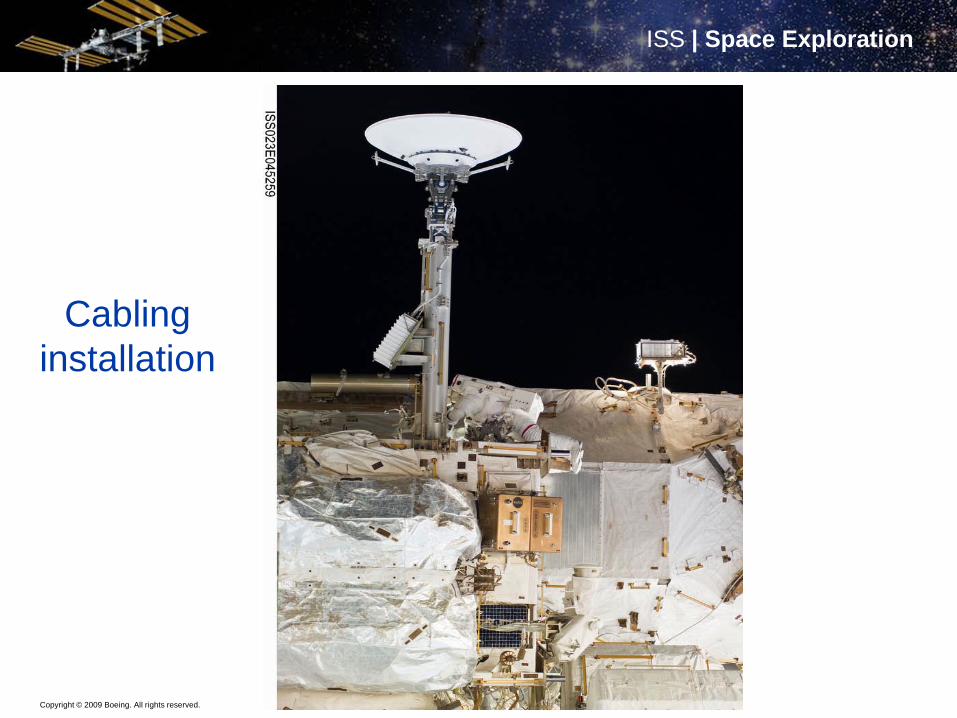
Cabling installation
Copyright © 2009 Boeing. All rights reserved.
ISS | Space ExplorationISS | Space Exploration
Activation and Operations• Since the internal IF (Intermediate Frequency) cables required for the
redundant hardware were not installed at the time of ULF4 mission, the official checkout was tentatively scheduled for the following increment
• When it became apparent that the cable routing was going to slip due to higher priority activities, the ISS C&T team received approval to perform a forward link test to verify antenna pointing and measure the forward link insertion losses– The test was performed using TDRS 171– Results: Approximately 1dB better than the existing Ku-Band
hardware (expected due to better RF characteristics on this string)
• Official Activation:– On July 26, 2011, the Redundant SGTRC and SGANT were
officially activated and remain in operation (to be operated for 6 months at a time alternating with original Antenna Group)
Copyright © 2009 Boeing. All rights reserved.
ISS | Space ExplorationISS | Space Exploration
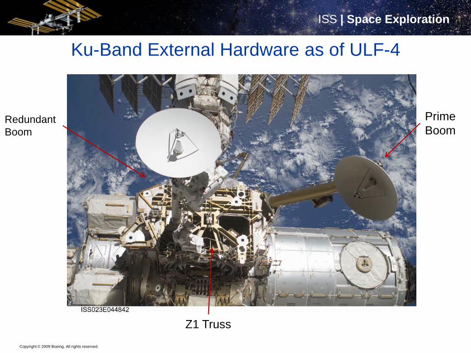
Ku-Band External Hardware as of ULF-4
Z1 Truss
Redundant Boom
Prime Boom
Copyright © 2009 Boeing. All rights reserved.
ISS | Space ExplorationISS | Space Exploration
Conclusion• The ISS in the Assembly Complete form continues to offer a variety
of means to add external capabilities beyond the original design– The incremental build up left some temporary connections useful
for upgrades– There is a limit to the number of signal (digital and analog)
connections available for future growth• Development of multiplexors may at some time become necessary
if growth continues• Growth and evolution of the ISS is possible in response to both new
technologies and as new needs emerge– New Payloads being launched and activated on-orbit– Internal modem and multiplexor upgrades are in progress to
reduce bottlenecks and double the link bandwidth utilizing the existing Ku-Band SGANT and SGTRC