Embed Size (px)
Citation preview
Adding Functionality to Autodesk Revit Structure Tomas Amor PE – Target Stuart Zimmermann – Target
SE3281 It is time to move on from using Autodesk Revit Structure software as a drafting tool and to begin using it as a design aid by accessing and manipulating the information in the model. This class will show how additional functionality can be added to Revit Structure in two ways. First, we will show how to incorporate structural engineering calculations into families that can be used to drive the geometry of modeled elements. Second, we will demonstrate a link between Revit and Microsoft® Excel® that allows use of system, type, and instance parameters in one formula and creates new parameters that report information contained in the model that is typically inaccessible through Revit reporting tools. We hope these examples will inspire you to find innovative and creative solutions using Revit tools.
Learning Objectives At the end of this class, you will be able to:
• Using Revit Structure as a design tool
• Edit families for design and documentation of structural elements
• Utilize Revit’s native tools to add functionality
• Automate repetitive tasks by using creative solutions
About the Speakers Tomas Amor P.E. is a Structural Engineer at Target with over 12 years of experience that has been working on Revit® since release 4. He led the transition to Revit® at his previous firm and is actively involved in Target's strategic development and implementation of BIM. He has an interest in improving processes with the use of technology innovation. Tomas is a Licensed Professional Engineer, certified Revit Professional, and has an MBA from the University of St. Thomas, a B.S. in Civil Engineering from the University of Minnesota, and an Associate Degree in Civil Engineering Technology from Chippewa Valley Technical College.
Stuart Zimmermann is a Sr. BIM Specialist at Target, one of the most renowned and influential retail driven organizations in the world. As a certified Revit Professional, he is currently partnering in the effort to build a world class BIM system to be used to service many cross functional teams both within Target and abroad. With over 15 years of experience in the architectural design and construction world and partnering with corporations such as Best Buy, Macy's and Marshall Fields, Stuart provides a professional owners perspective to the BIM environment. Stuart holds an Associates of Science in Architectural Design Technology from Northwest Technical Institute and is a certified Revit professional since 2009. [email protected]

Adding Functionality to Autodesk Revit Structure
2
Revit Structure as a design aid
Since its inception, Revit has been used by many structural firms as a replacement for CAD. Although many have embraced the bidirectional links available with different structural analysis software, it’s few that rely on Revit as a design aid. This class is intended to encourage and inspire those professionals to think of ways to improve traditional design processes by showing easy ways to add functionality to Revit.
Using the “I” in BIM We have all heard this before many times, yet we continue to use only a fraction of the information in our models. It’s true that some information is hard to access or report, but with the appropriate tools and mindset we can achieve surprising results.
Have you ever tried to report the clear distance between the top of slab and bottom of structure above? All the information necessary is in the model, but how do you access it? Adding a few parameters to your framing families, using one of the Revit-Excel add-ins available, and creating some filters will do it.
Add calculations to drive 3-Dimensional families For some time we have seen calculations being added to detail components for detailing. Why not add engineering calculations to 3D families to drive geometry and design certain components in Revit?
Plan Ahead! Simple families can evolve to be complex as you add functionality to them. Try to account for future data needs in your components. Plan and manage your parameter naming and type conventions so they are useful in formulas. Avoid using formula syntax in the parameter name (ie. use “PhiVn” instead of “Phi*Vn”).
We will discuss the creation of three families:
• Rectangular footing • Headed stud • Embed plate with headed studs
Incorporate family calculations into the design workflow When creating and modifying Revit families be aware of what you are trying to accomplish. Many out of the box (OOTB) families are already set up to do what you want them to do, so try to keep edits to a minimum.
Figure out your threshold for creating new content versus using out of the box content.
Stick to it! Once you have your threshold in place only adjust it if need be.
Improve traditional processes adapting to new technology Traditionally, we are used to using one software for a specific individual task. We typically rely on transferring information from one to the next manually, creating inefficiencies and potential for human error. Processes can be improved considerably taking some time to develop automated data transfers and exploiting some tools within Revit.
Adding Functionality to Autodesk Revit Structure
3
Revit and Excel data exchange
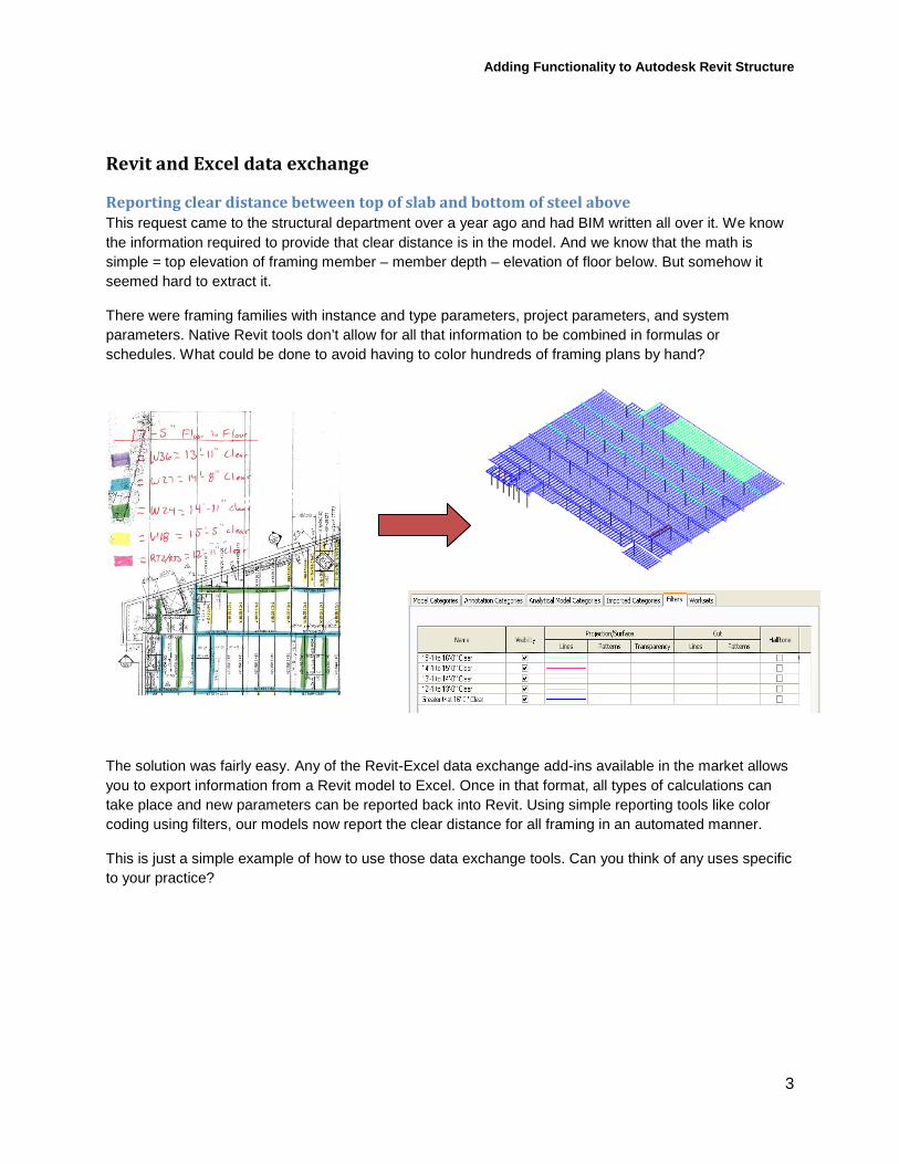
Reporting clear distance between top of slab and bottom of steel above This request came to the structural department over a year ago and had BIM written all over it. We know the information required to provide that clear distance is in the model. And we know that the math is simple = top elevation of framing member – member depth – elevation of floor below. But somehow it seemed hard to extract it.
There were framing families with instance and type parameters, project parameters, and system parameters. Native Revit tools don’t allow for all that information to be combined in formulas or schedules. What could be done to avoid having to color hundreds of framing plans by hand?
The solution was fairly easy. Any of the Revit-Excel data exchange add-ins available in the market allows you to export information from a Revit model to Excel. Once in that format, all types of calculations can take place and new parameters can be reported back into Revit. Using simple reporting tools like color coding using filters, our models now report the clear distance for all framing in an automated manner.
This is just a simple example of how to use those data exchange tools. Can you think of any uses specific to your practice?
Adding Functionality to Autodesk Revit Structure
4
Understanding the changes to the joist family
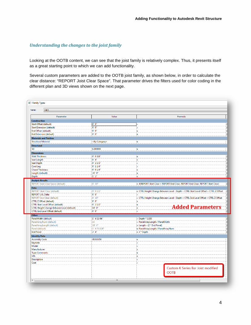
Looking at the OOTB content, we can see that the joist family is relatively complex. Thus, it presents itself as a great starting point to which we can add functionality.
Several custom parameters are added to the OOTB joist family, as shown below, in order to calculate the clear distance: “REPORT Joist Clear Space”. That parameter drives the filters used for color coding in the different plan and 3D views shown on the next page.
Added Parameters
Adding Functionality to Autodesk Revit Structure
5
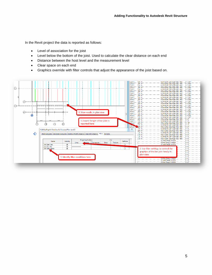
In the Revit project the data is reported as follows:
• Level of association for the joist • Level below the bottom of the joist. Used to calculate the clear distance on each end • Distance between the host level and the measurement level • Clear space on each end • Graphics override with filter controls that adjust the appearance of the joist based on.
Adding Functionality to Autodesk Revit Structure
6
Calculations in structural Revit families
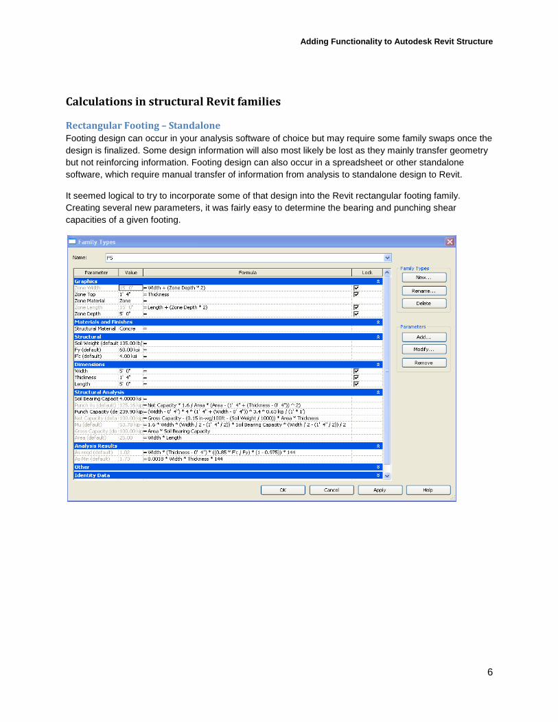
Rectangular Footing – Standalone Footing design can occur in your analysis software of choice but may require some family swaps once the design is finalized. Some design information will also most likely be lost as they mainly transfer geometry but not reinforcing information. Footing design can also occur in a spreadsheet or other standalone software, which require manual transfer of information from analysis to standalone design to Revit.
It seemed logical to try to incorporate some of that design into the Revit rectangular footing family. Creating several new parameters, it was fairly easy to determine the bearing and punching shear capacities of a given footing.
Adding Functionality to Autodesk Revit Structure
7
Understanding the Rectangular Footing Family
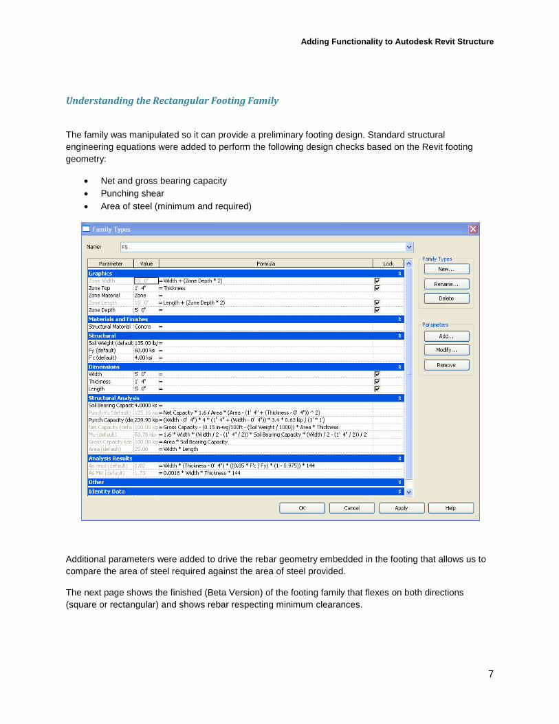
The family was manipulated so it can provide a preliminary footing design. Standard structural engineering equations were added to perform the following design checks based on the Revit footing geometry:
• Net and gross bearing capacity • Punching shear • Area of steel (minimum and required)
Additional parameters were added to drive the rebar geometry embedded in the footing that allows us to compare the area of steel required against the area of steel provided.
The next page shows the finished (Beta Version) of the footing family that flexes on both directions (square or rectangular) and shows rebar respecting minimum clearances.
Adding Functionality to Autodesk Revit Structure
8
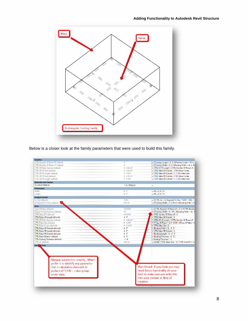
Below is a closer look at the family parameters that were used to build this family.
Adding Functionality to Autodesk Revit Structure
9
Embed plate – Standalone Anyone that has designed embed plates using ACI’s Appendix D knows they are repetitive and not fun to do by hand. Due to the nature of Target’s typical wall systems, many of the variables in that design can be standardized and the math can be simplified.
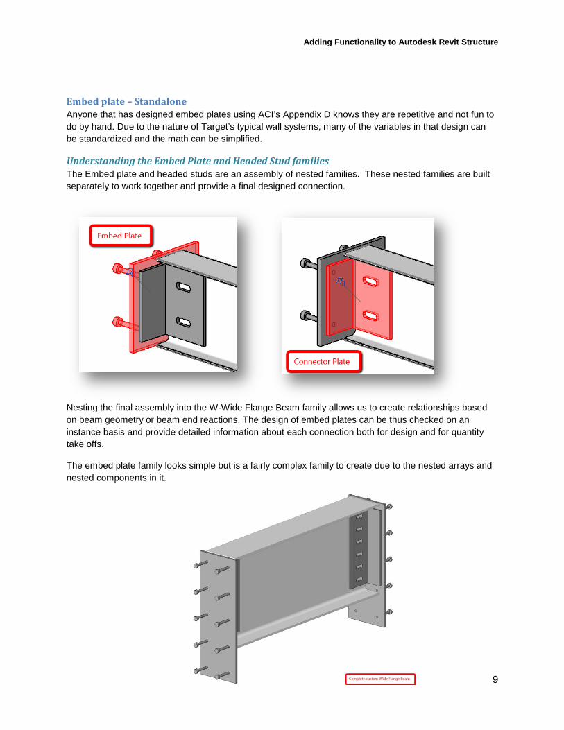
Understanding the Embed Plate and Headed Stud families The Embed plate and headed studs are an assembly of nested families. These nested families are built separately to work together and provide a final designed connection.
Nesting the final assembly into the W-Wide Flange Beam family allows us to create relationships based on beam geometry or beam end reactions. The design of embed plates can be thus checked on an instance basis and provide detailed information about each connection both for design and for quantity take offs.
The embed plate family looks simple but is a fairly complex family to create due to the nested arrays and nested components in it.
Adding Functionality to Autodesk Revit Structure
10
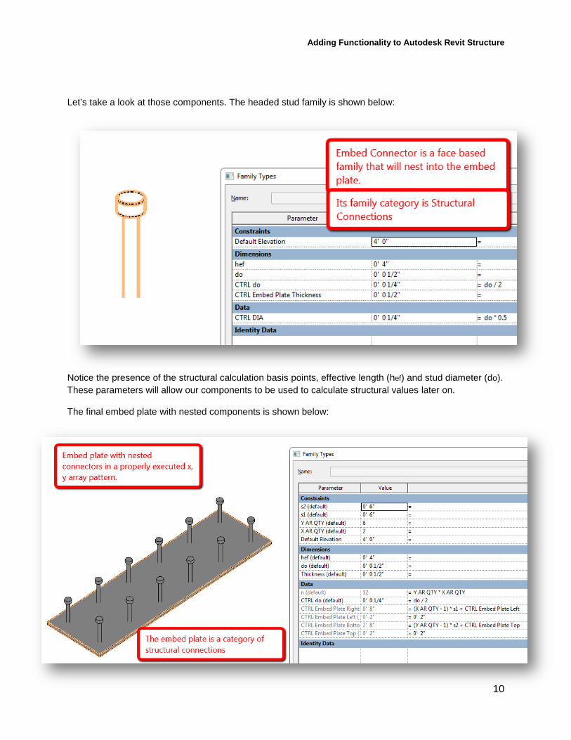
Let’s take a look at those components. The headed stud family is shown below:
Notice the presence of the structural calculation basis points, effective length (hef) and stud diameter (do). These parameters will allow our components to be used to calculate structural values later on.
The final embed plate with nested components is shown below:
Adding Functionality to Autodesk Revit Structure
11
Improving design processes
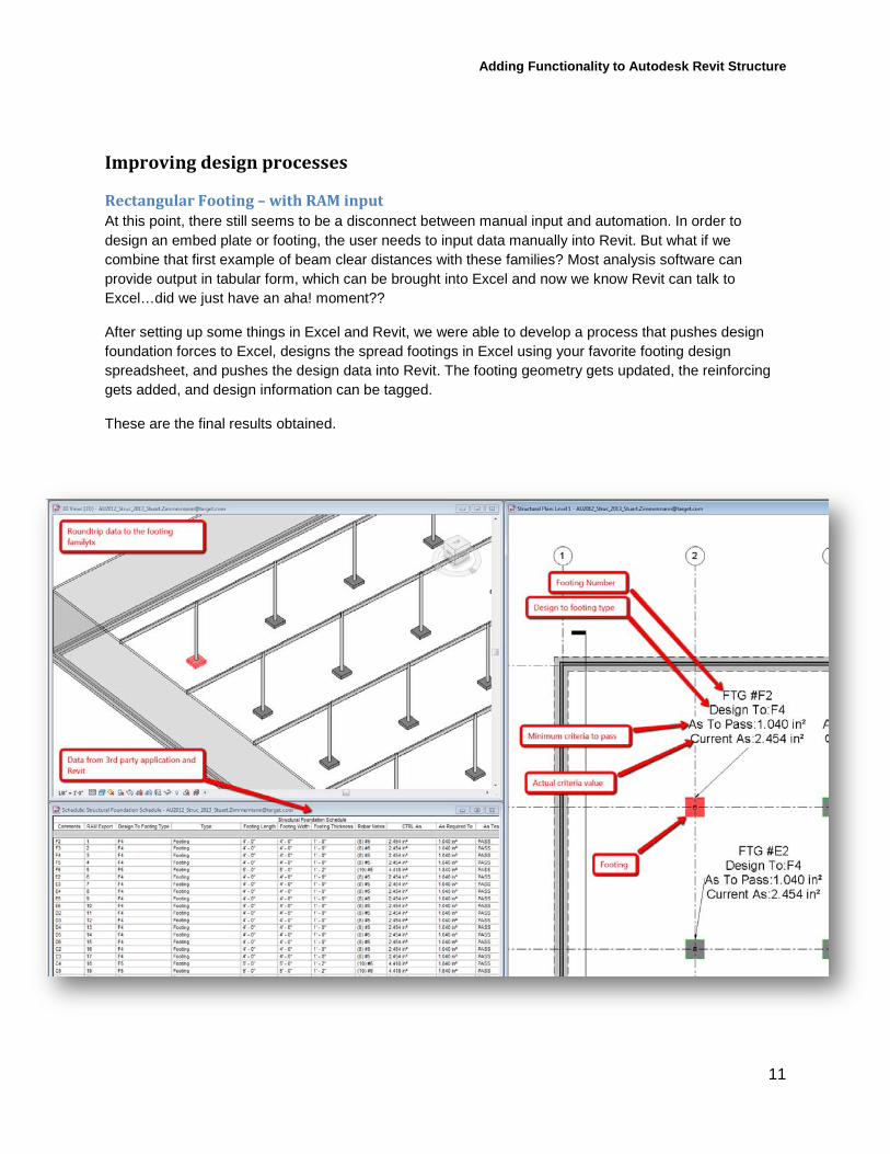
Rectangular Footing – with RAM input At this point, there still seems to be a disconnect between manual input and automation. In order to design an embed plate or footing, the user needs to input data manually into Revit. But what if we combine that first example of beam clear distances with these families? Most analysis software can provide output in tabular form, which can be brought into Excel and now we know Revit can talk to Excel…did we just have an aha! moment??
After setting up some things in Excel and Revit, we were able to develop a process that pushes design foundation forces to Excel, designs the spread footings in Excel using your favorite footing design spreadsheet, and pushes the design data into Revit. The footing geometry gets updated, the reinforcing gets added, and design information can be tagged.
These are the final results obtained.
Adding Functionality to Autodesk Revit Structure
12
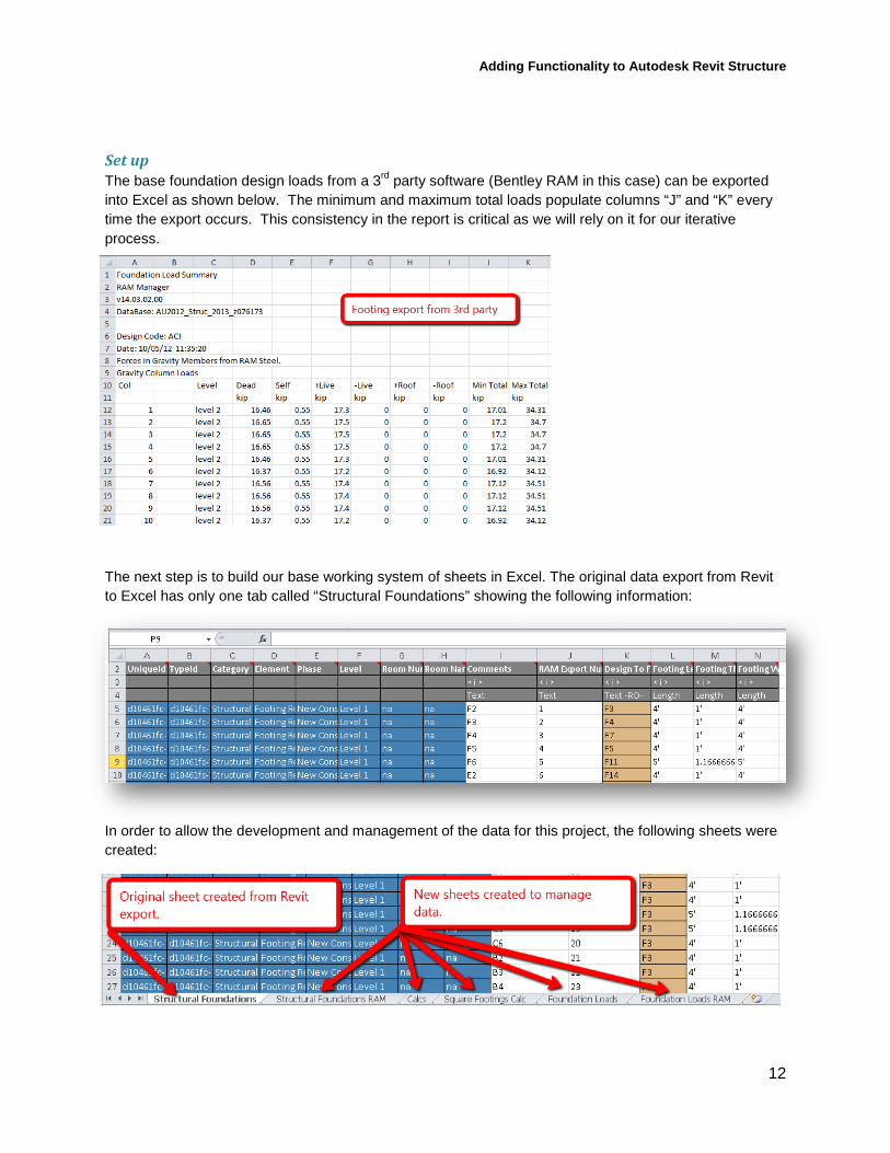
Set up The base foundation design loads from a 3rd
party software (Bentley RAM in this case) can be exported into Excel as shown below. The minimum and maximum total loads populate columns “J” and “K” every time the export occurs. This consistency in the report is critical as we will rely on it for our iterative process.
The next step is to build our base working system of sheets in Excel. The original data export from Revit to Excel has only one tab called “Structural Foundations” showing the following information:
In order to allow the development and management of the data for this project, the following sheets were created:
Adding Functionality to Autodesk Revit Structure
13
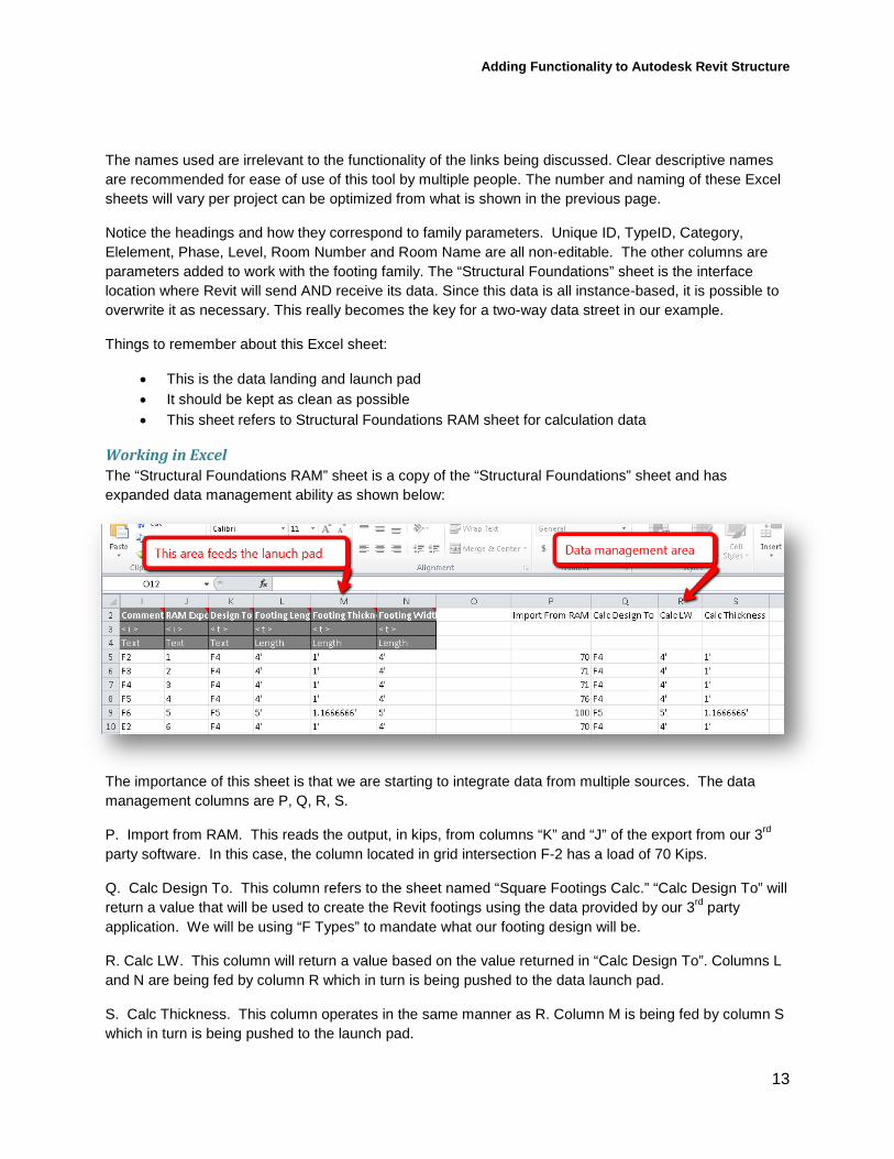
The names used are irrelevant to the functionality of the links being discussed. Clear descriptive names are recommended for ease of use of this tool by multiple people. The number and naming of these Excel sheets will vary per project can be optimized from what is shown in the previous page.
Notice the headings and how they correspond to family parameters. Unique ID, TypeID, Category, Elelement, Phase, Level, Room Number and Room Name are all non-editable. The other columns are parameters added to work with the footing family. The “Structural Foundations” sheet is the interface location where Revit will send AND receive its data. Since this data is all instance-based, it is possible to overwrite it as necessary. This really becomes the key for a two-way data street in our example.
Things to remember about this Excel sheet:
• This is the data landing and launch pad • It should be kept as clean as possible • This sheet refers to Structural Foundations RAM sheet for calculation data
Working in Excel The “Structural Foundations RAM” sheet is a copy of the “Structural Foundations” sheet and has expanded data management ability as shown below:
The importance of this sheet is that we are starting to integrate data from multiple sources. The data management columns are P, Q, R, S.
P. Import from RAM. This reads the output, in kips, from columns “K” and “J” of the export from our 3rd
Q. Calc Design To. This column refers to the sheet named “Square Footings Calc.” “Calc Design To” will return a value that will be used to create the Revit footings using the data provided by our 3
party software. In this case, the column located in grid intersection F-2 has a load of 70 Kips.
rd
R. Calc LW. This column will return a value based on the value returned in “Calc Design To”. Columns L and N are being fed by column R which in turn is being pushed to the data launch pad.
party application. We will be using “F Types” to mandate what our footing design will be.
S. Calc Thickness. This column operates in the same manner as R. Column M is being fed by column S which in turn is being pushed to the launch pad.
Adding Functionality to Autodesk Revit Structure
14
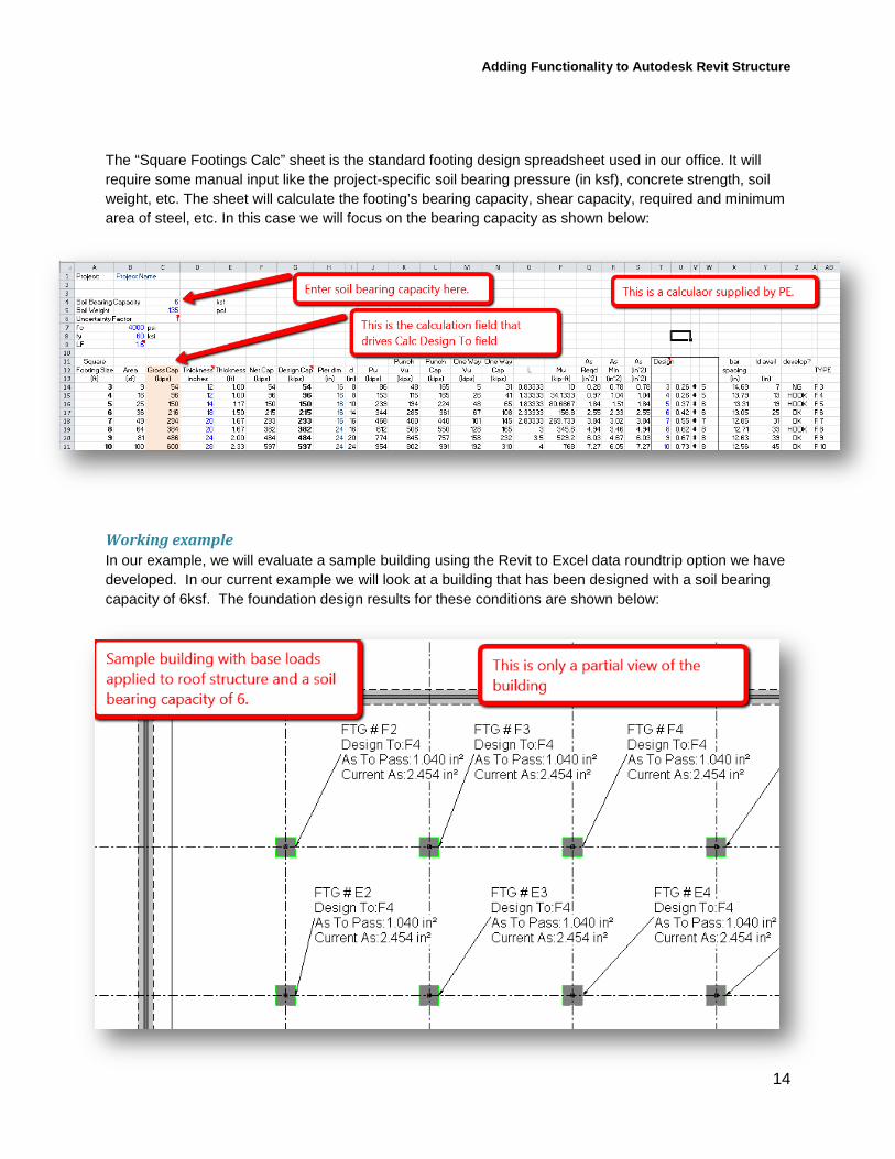
The “Square Footings Calc” sheet is the standard footing design spreadsheet used in our office. It will require some manual input like the project-specific soil bearing pressure (in ksf), concrete strength, soil weight, etc. The sheet will calculate the footing’s bearing capacity, shear capacity, required and minimum area of steel, etc. In this case we will focus on the bearing capacity as shown below:
Working example In our example, we will evaluate a sample building using the Revit to Excel data roundtrip option we have developed. In our current example we will look at a building that has been designed with a soil bearing capacity of 6ksf. The foundation design results for these conditions are shown below:
Adding Functionality to Autodesk Revit Structure
15
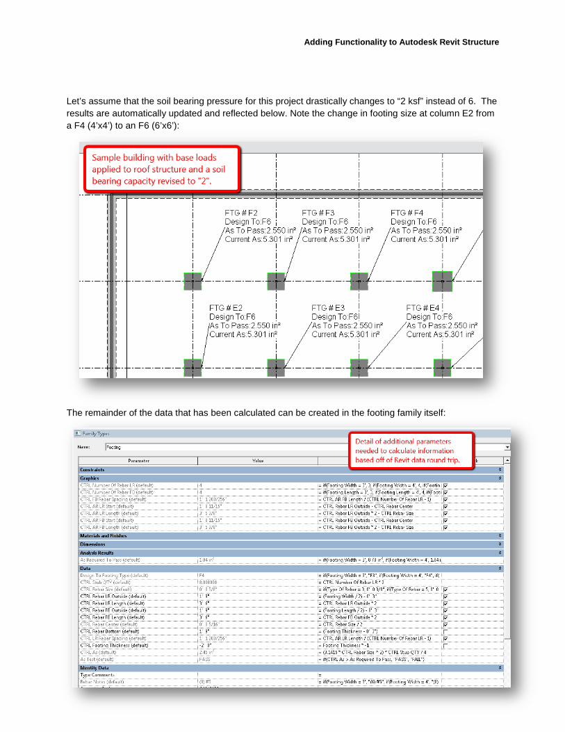
Let’s assume that the soil bearing pressure for this project drastically changes to “2 ksf” instead of 6. The results are automatically updated and reflected below. Note the change in footing size at column E2 from a F4 (4’x4’) to an F6 (6’x6’):
The remainder of the data that has been calculated can be created in the footing family itself:
Adding Functionality to Autodesk Revit Structure
16
Embed plate – with RAM Like the footing family, the embed plate as a standalone tool may not be the most practical as a design aid. A similar workflow can be developed to that shown for the footing sharing data through the Excel-Revit interoperability, since RAM can report reactions at each end of the beam. However, we want to propose a different way to tap into that information.
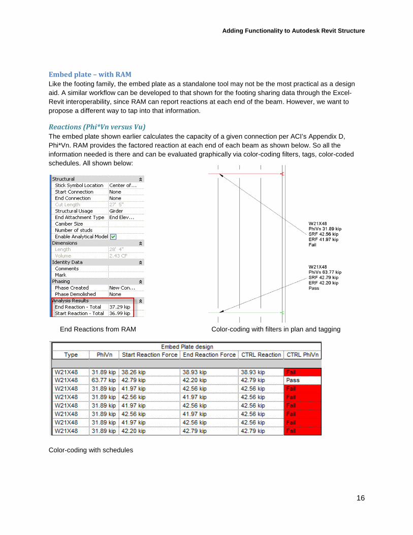
Reactions (Phi*Vn versus Vu) The embed plate shown earlier calculates the capacity of a given connection per ACI’s Appendix D, Phi*Vn. RAM provides the factored reaction at each end of each beam as shown below. So all the information needed is there and can be evaluated graphically via color-coding filters, tags, color-coded schedules. All shown below:
End Reactions from RAM Color-coding with filters in plan and tagging
Color-coding with schedules