Embed Size (px)
Citation preview

Lab Manual for TCP 17051
Page | 1
MASTERs 2013 Lab Manual for TCP 17051
Table of Contents Hardware Architecture 2 Lab 1 Instructions 4 Appendix A: Command Reference 12 Appendix B: Reference documents 17 Appendix C: Schematics 18
Adding Wi-Fi to Embedded Designs Using the RN-131/RN-171 modules
Lab Manual for TCP 17051
Page | 2
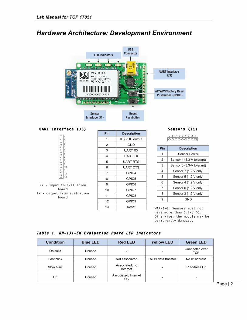
Hardware Architecture: Development Environment
UART Interface (J3)
RX - input to evaluation board
TX - output from evaluation board
Pin Description
1 3.3 VDC output
2 GND
3 UART RX
4 UART TX
5 UART RTS
6 UART CTS
7 GPIO4
8 GPIO5
9 GPIO6
10 GPIO7
11 GPIO8
12 GPIO9
13 Reset
Sensors (J1)
Pin Description
1 Sensor Power
2 Sensor 4 (3.3-V tolerant)
3 Sensor 5 (3.3-V tolerant)
4 Sensor 7 (1.2 V only)
5 Sensor 5 (1.2 V only)
6 Sensor 4 (1.2 V only)
7 Sensor 6 (1.2 V only)
8 Sensor 3 (1.2 V only)
9 GND WARNING: Sensors must not have more than 1.2-V DC. Otherwise, the module may be permanently damaged.
Table 1. RN-131-EK Evaluation Board LED Indicators
Condition Blue LED Red LED Yellow LED Green LED
On solid Unused -‐ -‐ Connected over TCP
Fast blink Unused Not associated Rx/Tx data transfer No IP address
Slow blink Unused Associated, no Internet -‐ IP address OK
Off Unused Associated, Internet OK -‐ -
SensorInterface (J1)
LED Indicators
UART Interface (J3)
ResetPushbutton
USBConnector
AP/WPS/Factory ResetPushbutton (GPIO9)
12345678910111213
9 5 234678 1

Lab Manual for TCP 17051
Page | 3
Lab Equipment
For this lab, you need the following hardware and software. Hardware
• RN-131-EK evaluation board, which contains the RN-131 WiFly module • Personal computer with a USB port • USB cable to interface the RN-131-EK to the PC • Access point(s) configured with WAP2 security (this hardware is already set up in
the lab by the instructor) Software
• Tera Term software (http://sourceforge.jp/projects/ttssh2/releases/) Access Point Setup
• We have four Access Points set up for this class, each having a unique SSID • Three Access Point are configured with WAP2-Personal encryption • One Access Point is open (has no security enabled)

Lab Manual for TCP 17051
Page | 4
Lab 1: Association and Data Transmission over TCP
Purpose:
This lab will teach you how to:
• Configure the module’s parameters. • Scan, join, and authenticate to wireless networks. • Discover the WiFly module on your wireless network via UDP. • Send data over TCP using the RN-131-EK to your lab partner.

Page | 5
Overview: The following steps will show you how to:
1. Set up the hardware. 2. Configure the module on the evaluation kit. 3. Associate with a network. 4. Discover the module on the network via UDP broadcast. 5. Send data to your lab partner using TCP.
Part 1: Hardware Setup 1. Connect the evaluation board.
a. Connect the RN-131-EK board to your computer using the USB cable. b. Use the device manager to find the COM port. See the following figures.
2. Launch the Tera Term terminal software from your PC.
a. Choose Serial. b. In the drop-down menu, select the COM port you found in step 1b.

Lab Manual for TCP 17051
Page | 6
3. Configure the RN-131-EK to enter command mode: a. Type the escape sequence (three dollar signs, $$$). b. The module responds with CMD. When you press the enter key, Tera Term
console displays the version prompt. 4. Review the module’s configuration and initialize the module to the factory default
conditions: a. Check the configuration and firmware version:
i. ver b. Perform a factory reset (starts the module in a known state):
i. factory RESET ii. reboot
You have completed the hardware setup. Example Output: CMD <4.00> ver wifly-GSX Ver 4.00.1, Apr 19 2013 11:48:31 on RN-131 <4.00> factory RESET Set Factory Defaults <4.00> reboot *Reboot*.wifly-GSX Ver 4.00.1, Apr 19 2013 11:48:28 on RN-131 MAC Addr=00:06:66:21:3a:08 *READY*

Lab Manual for TCP 17051
Page | 7
Part 2: Associating with a Wireless Network (Access Points) 1. Search for wireless networks.
a. $$$ (enter command mode) b. scan
Example Output: <4.00> scan <4.00> SCAN:Found 15 01,01,-69,08,1104,28,00,00:1a:70:74:15:43,youllneverbelievewhatsinside 02,01,-67,08,3104,28,00,06:90:e8:25:54:86,Moxa 03,01,-73,08,3104,28,00,84:c9:b2:65:5b:54,ADoctorADayKeepsAnAppleAway 04,01,-70,08,3104,28,00,00:15:f9:38:bd:b0,laptastic 05,01,-66,04,1100,28,c0,00:22:3f:6b:95:42,SensorNet 06,01,-74,04,3100,28,00,e0:91:f5:a9:8a:a0,accelbiotech 07,06,-58,06,3100,14,00,d8:c7:c8:aa:e7:a0,mchp-peap 08,06,-65,00,2100,00,00,d8:c7:c8:aa:e7:a1,guest 09,06,-57,08,3100,28,00,d8:c7:c8:aa:e7:a2,mchp-secure 10,06,-52,04,3104,28,00,b8:c7:5d:06:d0:2b, 11,06,-53,04,3104,28,00,00:26:f2:4f:89:d6,roving-guest 12,09,-49,04,3104,28,00,e0:91:f5:57:a3:54, 13,11,-48,04,3104,28,00,00:16:b6:45:63:98,CoolBox 14,11,-64,04,3108,28,00,00:14:d1:af:12:0c,roving1 15,11,-72,00,2100,40,40,00:18:02:70:7e:e8,GPT END:
The scan output format is shown below:
Index Channel RSSI Security Mode
Capabilities WPA Configuration
WPS Mode
MAC Address
SSID
For a more detailed description of the scan output fields, refer to the WiFly Command Reference, Advanced Features & Applications User’s Guide. NOTE 1: If you do not see the desired access point in the list, re-issue the scan
command. 2: The module does not display hidden access points in the scan output.

Lab Manual for TCP 17051
Page | 8
2. Auto-join a network with persistent configuration. a. set wlan ssid <string> // AP name b. set wlan pass <string> // AP passphrase c. set wlan join 1 // Enable auto-join to AP after reboot d. set option deivce-id <string> //Give your module a unique device name e. save f. reboot
Example Output: <4.00> set wlan ssid roving1 AOK <4.00> set wlan pass rubygirl AOK <4.00> set wlan join 1 AOK <4.00> save Storing in config <4.00> reboot *Reboot*.wifly-GSX Ver 4.00.1, Apr 19 2013 11:48:28 on RN-131 MAC Addr=00:06:66:21:3a:08 *READY* Auto-Assoc roving1 chan=11 mode=MIXED SCAN OK Joining roving1 now.. Associated! DHCP: Start DHCP in 17ms, lease=60s IF=UP DHCP=ON IP=172.35.1.13:2000 NM=255.255.0.0 GW=172.35.0.1 Listen on 2000
TIP: If the network is secure, set the pass phrase with set wlan pass <string> before
joining the network.

Lab Manual for TCP 17051
Page | 9
Part 3: Discovering Your Devices on the Network Using the UDP Broadcast Protocol NOTE: You will be observing this section. There is no action required. The following figure illustrates device discovery via UDP broadcast. The module sends a UDP broadcast at programmable intervals to make itself discoverable. The UDP broadcast contains information that identifies the module on the network. Device Discovery via UDP Broadcast
The UDP broadcast is a fixed 110 byte packet with the following structure:
Roving Networks Device
192.168.0.3
Access Point DHCP server
Roving Networks Device
192.168.0.2
192.168.0.1
174.201.25.16
To Internet
Roving Networks Device
Roving Networks Device
Roving Networks Device
Roving Networks Device
Roving Networks Device
192.168.0.4
192.168.0.5
192.168.0.6
192.168.0.7
192.168.0.8
192.168.0.100 UDP Server
Who is there
I’m here
I’m here
I’m here
I’m here
I’m here
I’m here
I’m here
0 - 5 6 7 8 - 9 10 - 13 14 - 15 16 - 17 18 - 31 32 - 59 60 - 91 92 - 93 94 - 110
Programmable Device ID Set with set option deviceid <string> (32 Bytes)Version String with Date Code (26 Bytes)
ASCII Time (13 Bytes)
GPIO Pin Value (2 Bytes)
Access Point’s MAC Address (6 Bytes)Channel (1 Byte)
RSSI (1 Byte)
Local TCP Port (2 Bytes)
Pin 20’s Battery Voltage in mV, e.g., 2755 (2 Bytes)
RTC Value, MSB to LSB (4 Bytes)
Position
Sensor 0 - 7 Voltage Readings Enabled with set opt format <mask> (16 Bytes)Boot Time in ms (2 Bytes)

Lab Manual for TCP 17051
Page | 10
Part 4: Communicating with your lab partner over TCP This lab section will teach you how to:
• Connect from the module to a remote host using TCP (client). • Connect to module from remote host using TCP (server).
Student A’s module initiates the TCP open and acts as the client. Student B’s module accepts the TCP connection and acts as the server. TCP connections are point-to-point connections that provide reliable, guaranteed, in order data delivery. They are also known as sockets. See the following figure. TCP Connections
1. Restore the module to the factory defaults: a. $$$ // Enter command mode. b. factory RESET // Restore module to factory defaults c. reboot // Reboot module with factory defaults
2. Associate with AP a. $$$ // Enter command mode b. set wlan ssid <string> // Enter AP SSID c. set wlan pass <string> // Enter AP passphrase d. set wlan join 1 // Enable auto join e. save f. reboot
WiFly Module Opens TCP Connection
Sensing applications Sending data to web server Data acquisition systems Fleet management
Remote Host Opens TCP Connection
Industrial controls Home automation Universal remotes
open 192.168.1.200 5000 open 192.168.1.50 2000
RN-134-K
192.168.1.50 Listen on Port 2000
Access Point DHCP server
Remote Host
192.168.1.200 Listen on Port 5000

Lab Manual for TCP 17051
Page | 11
3. Check and note your module’s IP address at this stage. Example Output: *Reboot*.wifly-GSX Ver 4.00.1, Apr 19 2013 11:48:28 on RN-131 MAC Addr=00:06:66:21:3a:08 *READY* Auto-Assoc roving1 chan=11 mode=MIXED SCAN OK Joining roving1 now.. Associated! DHCP: Start DHCP in 17ms, lease=60s IF=UP DHCP=ON IP=172.35.1.13:2000 NM=255.255.0.0 GW=172.35.0.1 Listen on 2000
My module’s IP address:________________________
4. Student A, open a TCP connection to your lab partner: a. $$$ // Enter command mode b. open <Lab Partner IP address> 2000 // 2000 is the port number
*OPEN* is shown on student A’s Tera Term window and a packet with *HELLO* is shown on student B’s Tera Term window. At this point, either student can type data in their Tera Term window and it is sent over Wi-Fi to your partner’s module using TCP.
5. Close the TCP connection: a. $$$ // Enter command mode. b. close // Issue command to close TCP connection
Tera Term displays the close string, *CLOS*.

Lab Manual for TCP 17051
Page | 12
Appendix A: Command Quick Reference
Set Commands (Part 1 of 4) Command Default Description
set adhoc beacon <value> 102 Sets the ad hoc beacon interval in milliseconds. set adhoc probe <value> 5 Sets the ad hoc probe timeout in seconds (ad hoc
mode only). set adhoc reboot <value> 0 Sets the reboot timer. set broadcast address <address>
255.255.255.255 Sets the address to which the UDP hello/heartbeat message is sent.
set broadcast backup <address>
0.0.0.0 Sets the secondary broadcast backup address.
set broadcast interval <mask> 7 Sets the interval (in seconds) at which the hello/heartbeat UDP message is sent.
set broadcast port <value> 55555 Sets the port to which the UDP hello/heartbeat message is sent.
set broadcast remote <port> 0 Sets the secondary broadcast port. set comm $ <char> $ Sets character used to enter command mode to
<char>. set comm close <string> *CLOS* Sets the ASCI string that is sent to the local UART
when the TCP port is closed. set comm idle <value> 0 Sets the idle timer value in seconds. set comm match <value> | <hex>
0 Sets the match character in hex or decimal.
set comm open <string> *OPEN* Sets the ASCI string that is sent to the local UART when the TCP port is opened.
set comm remote <string> *HELLO* Sets the ASCI string that is sent to the remote TCP client when the TCP port is opened.
set comm size <value> 64 Sets the flush size in bytes. set comm time <value> 5 Sets the flush timer. set dhcp lease <value> 86400 Sets the soft AP mode DHCP lease time in seconds. set dns address <address> 0.0.0.0 Sets the IP address of the DNS sever. set dns backup <string> rn.microchip.com Sets the name of the backup host for TCP/IP
connections to <string>. set dns name <string> server1 Sets the name of the host for TCP/IP connections to
<string>. set ftp addr <address> 0.0.0.0 Sets the FTP server’s IP address of the FTP server. set ftp dir <string> public Sets the starting directory on the FTP server. set ftp filename <filename> See description Sets the name of the file that is transferred when
issuing the ftp u command, where <filename> is the firmware image. Firmware version 4.0 default is wifly3-<version>.img (RN131) wifly7-<version>.img (RN171). Firmware prior to 4.0 default is wifly-GSX-<version>.img (RN131) wifly-EZX-<version>.img (RN171).
set ftp pass <string> Pass123 Sets the password for accessing the FTP server. set ftp mode <mask> 0x0 Sets the ftp mode, where <mask> indicates active
or passive mode. Default is passive. set ftp remote <value> 21 Sets the FTP server’s remote port number.

Lab Manual for TCP 17051
Page | 13
Set Commands (Part 2 of 4) Command Default D
escription
set ftp time <value> 200 Sets the FTP timeout value, where <value> is a decimal number that is five times the number of seconds required.
set ftp user <string> roving Sets the user name for accessing the FTP server. set ip address <address> 0.0.0.0 Sets the WiFly module’s IP address. set ip backup <address> 0.0.0.0 Sets a secondary host IP address. set ip dhcp <value> 1 Enables/disables DHCP mode. set ip flags <mask> 0x7 Sets the TCP/IP functions. set ip gateway <address> 0.0.0.0 Sets the gateway IP address. set ip host <address> 0.0.0.0 Sets the remote host’s IP address. set ip localport <value> 2000 Sets the local port number. set ip netmask <address> 255.255.255.0 Sets the network mask. set ip protocol <flag> 2 Sets the IP protocol. set ip remote <value> 2000 Sets the remote host port number. set ip tcp-mode <mask> 0x0 Controls the TCP connect timers, DNS
preferences, and remote configuration options.
set opt average <value> 5 Sets the number of RSSI samples used to calculate the running RSSI average.
set opt deviceid <string> WiFly-XXX Sets the configurable device ID, where XXX is GSX for the RN131 and EZX for the RN171.
set opt format <flag> 0x00 Sets the HTTP client/web server information. set opt jointmr <value> 1000 Sets the join timer, which is the length of time (in
ms) the join function waits for the access point to complete the association process.
set opt replace <char> $ (0x24) Sets the replacement character you use to indicate spaces in the SSID and pass phrases, where <char> is a single character.
set opt password <string> “” (no password required)
Sets the TCP connection password.
set opt signal <value> 0 Configures the threshold level for the RSSI value in infrastructure mode.
set q power <value> 0 Automatically turns on the sensor power. set q sensor <mask> 0 Specifies which sensor pins to sample when
sending data using the UDP broadcast packet or the HTTP auto sample function.
set sys autoconn <value> 0 Sets the auto-connect timer in TCP mode. set sys autosleep <value> 0 Sets the auto-sleep timer in UDP mode. set sys iofunc <mask> 0x0 Sets the I/O port alternate functions. set sys launch_string <string> web_app Sets the application to launch when GPIO9 is high
after powerup. set sys mask <mask> 0x20F0 (RN131)
0x21F0 (RN171) Sets the I/O port direction.
set sys printlvl <value> 0x1 Controls the debug print messages printed by the WiFly module on the UART.
set sys output <mask> <mask> None Sets the output GPIO pins high or low. The optional <mask> sets a subset of the pins.

Lab Manual for TCP 17051
Page | 14
Set Commands (Part 3 of 4) Command Default Description
set sys sleep <value> 0 Sets the sleep timer. set sys trigger <flag> or <mask>
0x1 With this parameter setting, the module wakes from sleep state using the sensor input 0, 1, 2, and 3.
set sys value <mask> 0x0 Sets the default value of the GPIO pins’ outputs upon power-up.
set sys wake <value> 0 Sets the automatic wake timer in seconds. set time address <address> 64.90.182.55 Sets the time server address. set time enable <value> 0 Tells the module how often to fetch the time from the
specified SNTP time server in minutes. set time port <value> 123 Sets the time server port number. set time raw <value> None Allows you to set the RTC raw value from the
console in seconds. set uart baud <value> 9600 Sets the UART baud rate, where <value> is 2400,
4800, 9600, 19200, 38400, 57600, 115200, 230400, 460800, or 921600.
set uart flow <value> 0 Sets the flow control mode and parity. set uart instant <value> Not applicable Immediately changes the baud rate, where <value>
is 2400, 4800, 9600, 19200, 38400, 57600, 115200, 230400, 460800, or 921600.
set uart mode <mask> 0 Sets the UART mode register. set uart raw <value> Not applicable Sets a raw UART value. set uart tx <value> Not applicable Disables or enables the UART’s TX pin (GPIO10),
where <value> is 1 or 0. set wlan auth <value> 0 Sets the authentication mode. set wlan channel <value> <flag>
0 Sets the WLAN channel, where <value> is a decimal number from 1 to 13 representing a fixed channel and <flag> is the optional character i (meaning immediate).
set wlan ext_antenna <value> 0 Determines which antenna is active, where <value> is 0 (use the chip antenna) or 1 (use the U.FL connector).
set wlan fmon <value> 3600 Sets the soft AP mode link monitor timeout threshold for the associated client device.
set wlan id <string> – Reserved for future use. set wlan hide <value> 0 Hides the WEP key and WPA passphrase, where
<value> is 0 or 1. set wlan join <value> 1|0 Sets the policy for automatically associating with
network access points. set wlan key <value> Not applicable Sets the 128-bit WEP key, where <value> is
EXACTLY 26 ASCII chars (13 bytes) in hex without the preceding 0x.
set wlan linkmon <value> 0 (disabled) Sets the link monitor timeout threshold, where <value> is a decimal number representing the number of failed scans before the module declares AP is Lost and de-authenticates.
set wlan mask <mask> 0x1FFF (all chan- nels)
Sets the WLAN channel mask, which is used for scanning channels with auto-join policy 1 or 2).
set wlan phrase <string> rubygirl Sets the passphrase for WPA and WPA2 security modes. set wlan number <value> 0 Sets the WEP key number.

Lab Manual for TCP 17051
Page | 15
Set Commands (Part 4 of 4) Command Default Description
set wlan rate <value> 12 Sets the wireless data rate. set wlan ssid <string> roving1 Sets the SSID with which the module associates. set wlan tx <value> 0 Sets the Wi-Fi transmit power, where <value> is a
decimal number from 1 to 12 that corresponds to 1 to 12 dBm.
set wlan user <string> – Reserved for future use. Get Commands
Command Description
get adhoc Displays the ad hoc settings. get broadcast Displays the broadcast UPD address, port, and interval. get com Displays the communication settings. get dns Displays the DNS settings. get everything Displays all of the configuration settings, which is useful for debugging. get ftp Displays the FTP settings. get ip <char> Displays the IP address and port number settings, where <char> is the
optional parameter a. Using <char> returns the current IP address. get mac Displays the device’s MAC address. get option Displays the optional settings such as the device ID. get sys Displays the system settings, sleep and wake timers, etc. get time Displays the time server UDP address and port number. get wlan Displays the SSID, channel, and other WLAN settings. get uart Displays the UART settings. ver Displays the firmware version.
Status Commands
Command Description
show battery Displays current battery voltage, and is only applicable to Roving Networks’ battery-powered products such as the RN370 and temperature sensors (ISENSOR-CB).
show connection Displays the connection status in the hex format 8<XYZ>. show io Displays the GPIO pins’ level status in the hex format 8<ABC>. show net <char> Displays the current network status, association, authentication, etc., where
<char> is the optional parameter n. Using the n parameter displays only the MAC address of the access point with which the module is currently associated.
show q <value> Displays the value of the analog interface pin, where <value> is 0 to 7. show q 0x1<mask> Displays multiple analog interface values simultaneously. show rssi Displays the last received signal strength. show stats Displays the current statistics, packet RX/TX counters, etc. show time Displays the number of seconds since the module was last powered up or
rebooted.

Lab Manual for TCP 17051
Page | 16
Action Commands Command Description
$$$ Use this command to enter command mode. apmode <bssid> <chan- nel>
Creates a soft AP network. close Disconnects a TCP connection. exit Exits command mode. factory RESET Loads the factory defaults into the module’s RAM and writes the settings to
the standard configuration file. You must type the word RESET in capital letters.
join <string> Instructs the WiFly module to join the network indicated by <string>. join # <value> Use this command to join a network that is shown in the scan list, where
<value> is the entry number listed for the network in the scan list. leave Disconnects the module from the access point to which it is currently
associated. lookup <string> Causes the module to perform a DNS query for host name <string>. open <address> <value> Opens a TCP connection to <address>, where <value> is the port number. ping <string> <value> Pings a remote host, where <string> is a parameter setting and <value> is the
number of pings. The default is 1 packet. reboot Forces the module to reboot (similar to a power cycle). run Runs an application using ASCII commands. scan <value> <char> Performs an active probe scan of access points on all 13 channels. The
default is 200 ms/channel. sleep Puts the module to sleep. time Sets the real-time clock by synchronizing with the time server specified
with the time server (set time) parameters.
File I/O Commands Command Description
del <string> <value> Deletes a file. load <string> Reads in a new configuration file. ls Displays the files in the system. save <string> Saves the your configuration settings to a file. boot image <value> Makes a file represented by <value> the new boot image. ftp update <string> Deletes the backup image file, retrieves a new image file, and updates the
boot pointer to the new image.

Lab Manual for TCP 17051
Page | 17
Appendix B: Reference Documents For more information, refer to the following documentation:
• WiFly Command Reference, Advanced Features & Applications User’s Guide • RN-131G & RN-131C 802.11 b/g Wireless LAN Module Data Sheet • RN-171 802-11 b/g Wireless LAN Module Data Sheet • RN-131-PICTAIL & RN-171-PICTAIL Evaluation Boards User Manual

Lab Manual for TCP 17051
Page | 18
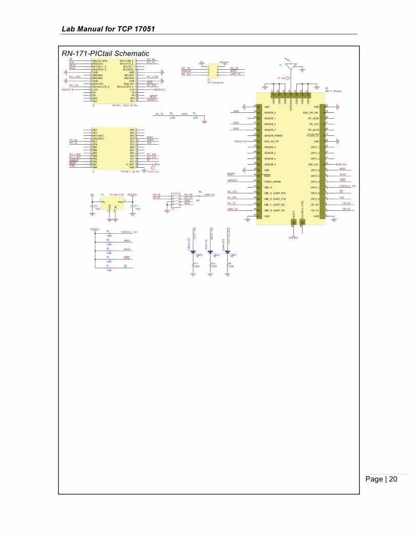
Appendix C: Schematics The following figures illustrate the RN-131-EK, RN-131-PICtail, and RN-171-PICtail schematics, respectively. RN-131 EK Board Schematic
SENS OR _POWER
SENSOR _4SENSOR _5SENSOR _7
SENSOR _6
SENSOR _5SENSOR _4SENSOR4_ P IN
SENSOR5_ P IN
SENSOR _0SENSOR _1SENSOR _3SENSOR _2GPIO _9
RX DCT S
100kR16
100kR9
100kR6
100kR7
100kR14
220kR5220kR10
220kR15220kR8
220kR11
123456789
J1
Sensor Interface
VDD_3V3
GPIO _8
GPIO _5GPIO _6GPIO _7
GPIO _4
RESET _NGPIO _9
TX DRX D
CT SRT S
12345678910111213
J3
UART I nterface
VBUS
D_ND_P
TXDRXD
RTSCTS
VBUS
RESET 18
3V3O
UT
16
USBDP 14
USBDM 15
GN
D17
CBUS210 CBUS121
VC
CIO
1
CBUS311
CBUS49
CBUS022
GN
D20
RI3 DCD7 DSR6 DTR31 CTS8 RTS32 RXD2 TXD30 VC
C19
OSCI 27
OSCO 28
AG
ND
24
TEST
26
GN
D4
THPA
D33
FT232RQU1
100nF
C2
100nF
C3
100nF
C1
GND5
D+3 D-2 VBUS1
MTAB 6
USB Mini B
J2
iPower Net
i Power Net3k3R13k3R33k3R23k3R4
GPIO _5
GPIO _6
GPIO _4
GPIO _6
GPIO _5
GPIO _4
GPIO _7
GPIO _8
GPIO _7
220R
R21
220R
R23
220R
R17
220R
R13
100k
R20
100k
R18
100k
R12
100k
R19
100k
R22
Blue
D4Green
D3Yellow
D2Red
D1
VDD_3V3
GPIO _9
S1
S2
RESET _N
SENSOR _0
SENSOR _1
SENSOR _2
SENSOR _3
SENSOR _6
SENSOR _7
SENSOR _4
SENSOR _5SENS OR _POWER
RESET _N
FOR CE _AWAKE
GPIO _8
GPIO _9
GPIO _5
GPIO _6
GPIO _7
GPIO _4
CT S
RT S
TX D
RX D
VDD_3V3
29 GPIO_429
30 SENSOR_130
31 SENSOR_231
32 SENSOR_332
33 SENSOR_POWER33
34 SENSOR_034
36
GN
D36
EPC_A 66
EPC_B 77
SUPERCAP_BAL ANCE 88
FORCE_AWAKE 99
UART_RTS(GPI O_13) 1010
UART_CTS(GPI O_12) 1111
UART_RX(GPI O_11) 1212
UART_TX (GPI O_10) 1313
SENSOR_6 11
SENSOR_4 22
SENSOR_5 33
SENSOR_7 44
RESET 55
SPI_
MO
SI
14
14
SPI_
SCK
1
515
SPI_
MIS
O
16
16
SREG
_OU
T
1717
SREG
_IN
1
818
GN
D
19
19
BA
TT
2020
VD
D
2121
ISP_
TX
22
22
23 ISP_RX23
24 GPIO_924
25 GPIO_825
26 GPIO_726
27 GPIO_627
28 GPIO_528
37
GN
D37
38
GN
D38
39
GN
D39
40
GN
D40
41
GN
D41
42
GN
D42
43
GN
D43
44
GN
D44
M1RN131 Module
100nFC4
VBUS
i Power NetVin1
GN
D2
Vout 3
Tab
4
TC1262- 3.3VDBTRU2
VDD_3V3
i Power Net

Lab Manual for TCP 17051
Page | 19
RN-131-PICtail Schematic
29 GPIO_429
30 SENSOR_130
31 SENSOR_231
32 SENSOR_332
33 SENSOR_POWER33
34 SENSOR_034
36
GN
D36
EPC_A 66
EPC_B 77
SUPERCAP_BAL ANCE 88
FORCE_AWAKE 99
UART_RTS(GPI O_13) 1010
UART_CTS(GPI O_12) 1111
UART_RX(GPI O_11) 1212
UART_TX (GPI O_10) 1313
SENSOR_6 11
SENSOR_4 22
SENSOR_5 33
SENSOR_7 44
RESET 55
SPI_
MO
SI
14
14
SPI_
SCK
1
515
SPI_
MIS
O
16
16
SREG
_OU
T
1717
SREG
_IN
1
818
GN
D
19
19
BA
TT
2020
VD
D
2121
ISP_
TX
22
22
23 ISP_RX23
24 GPIO_924
25 GPIO_825
26 GPIO_726
27 GPIO_627
28 GPIO_528
37
GN
D37
38
GN
D38
39
GN
D39
40
GN
D40
41
GN
D41
42
GN
D42
43
GN
D43
44
GN
D44
M2RN131 Module
VDD3V3
PIC_CTS
PIC_RTS
UART_TX
SS
SCK
MI SO
MOSI
ISP_TX
ISP_RX
STATUS_L EDWAKEUP
RESET
SI RQ
SEN2
SEN3
SEN0
PIC_TX
i Power Net
100k
R13100k
R15100k
R16100k
R17
STATUS_L ED
SS
MI SO
MOSI
SI RQ
100k
R14VDD3V3
SEN0100k
R22
220k
R21PI C_TX
10uFC3
10uFC4
VDD3V3
Vin1
GN
D2
Vout 3
Tab
4
TC1262- 3.3VU2Vin
i Power Net
220RR18
Gre
en L
ED
D4
STATU
S_LED
220RR19
Red
LED
D5
PIC_LED
R
220RR20
PIC_LED
Y
Yel
low
LED
D6
3k3R121
234
S2
UART_TXPI C_RXPI C_TX
ISP_TXISP_RX
SEN2SEN3
RB2/SS1/AN21 RF2/U1RX_E 2
RF6/SCK13 RF3/U1TX_E 4
RF7/SDI 1_E5 RG2/SCL 1 6
RF8/SDO1_E7 RG3/SDA1 8
GND9 GND 10
RB0/AN011 RB1/AN1 12
RB3/AN313 RB4/AN4 14
GND15 GND 16
RE9/I NT217 RE8/I NT1 18
RD14/U1CTS_E19 RD15/U1RTS_E 20
3.3V21 3.3V 22
5V23 5V 24
9V25 9V 26
RG027 RF0 28
RG129 RF1 30
J2 PI CTAI L PLUS 30 Pin
VDD3V3VDD3V3
PI C_CTS PI C_RTS
PI C_RXPI C_TX
SSSCKMI SOMOSI
RESETWAKEUP
PI C_L EDR
SI RQ
PI C_L EDY
RE21 RA5 2
RE33 RA4 4
RA7/OSC15 RA3 6
RA6/OSC27 RC5 8
RC79 RC4 10
RC611 RC3 12
RB713 RA0 14
RB615 RA1 16
RB517 RA2 18
RB419 RC0 20
RB321 RC1 22
RB223 RC2 24
RB125 V_VAR 26
RB027 GND 28
J1 PI CTAI L 28 Pin
PI C_TXPI C_RX
SCKMI SOMOSI
PI C_CTSPI C_RTS
WAKEUPRESET
PI C_L EDR
SI RQ
PI C_L EDY
iPower Net
SS
Vin
ISP_ TX
ISP_ R X
1 23 45 67 8
J3ISP Connector
UART_TX
PI C_TXRESETWAKEUP
VDD3V3
Lab Manual for TCP 17051
Page | 20
RN-171-PICtail Schematic
RB2/SS1/AN21 RF2/U1RX_E 2
RF6/SCK13 RF3/U1TX_E 4
RF7/SDI 1_E5 RG2/SCL 1 6
RF8/SDO1_E7 RG3/SDA1 8
GND9 GND 10
RB0/AN011 RB1/AN1 12
RB3/AN313 RB4/AN4 14
GND15 GND 16
RE9/I NT217 RE8/I NT1 18
RD14/U1CTS_E19 RD15/U1RTS_E 20
3.3V21 3.3V 22
5V23 5V 24
9V25 9V 26
RG027 RF0 28
RG129 RF1 30
J2 PI CTAI L PLUS 30 Pin
VDD3V3VDD3V3
PI C_CTS PI C_RTS
PI C_RXPI C_TX
SSSCKMI SOMOSI
RESETWAKEUP
PI C_L EDR
SI RQ
PI C_L EDY
RE21 RA5 2
RE33 RA4 4
RA7/OSC15 RA3 6
RA6/OSC27 RC5 8
RC79 RC4 10
RC611 RC3 12
RB713 RA0 14
RB615 RA1 16
RB517 RA2 18
RB419 RC0 20
RB321 RC1 22
RB223 RC2 24
RB125 V_VAR 26
RB027 GND 28
J1 PI CTAI L 28 Pin
PI C_TXPI C_RX
SCKMI SOMOSI
PI C_CTSPI C_RTS
WAKEUPRESET
PI C_L EDR
SI RQ
PI C_L EDY
iPower Net
SS
Vin
VDD3V3
Vin1
GN
D2
Vout 3
Tab
4
TC1262- 3.3VU1Vin
10uFC1
10uFC2
100k
R1100k
R3100k
R5100k
R4
STATUS_L ED
SS
MI SO
MOSI
SI RQ
100k
R2VDD3V3
220RR10
Gre
en L
ED
D1
STATU
S_LED
220RR9
Red
LED
D2
PIC_LED
R
220RR11
PIC_LED
Y
Yel
low
LED
D3
SEN0100k
R7
220k
R6PI C_TX
ISP_ TX
ISP_ R X
1 23 45 67 8
J3ISP Connector
UART_TX
PI C_TXRESETWAKEUP
VDD3V3
29 SENSOR_029
30 SENSOR_130
31 SENSOR_231
32 SENSOR_332
33 SENSOR_POWER33
34 VDD_3V3_RF34
35 SENSOR_435
36 SENSOR_536
GPI O_7 66
GPI O_6 77
GPI O_5 88
GPI O_4 99
VDD_3V3 1010
GPI O_3 1111
GPI O_2 1212
GPI O_1 1313
GND 11
ISP_TX 22
ISP_RX 33
GPI O_9 44
GPI O_8 55
GND 1414
FL ASH_CS 1515
SPI _MI SO 1616
SPI _SCK 1717
SPI _MOSI 1818
VDD_3V3_SW 1919
GND 2020
GN
D
21
21
GN
D
22
22
GN
D
23
23
AN
TEN
NA
2
424
GN
D
25
25
GN
D
26
26
GN
D
27
27
28 GND28
37 SENSOR_637
38 SENSOR_738
39 GND39
40 RESET40
41 FORCE_AWAKE41
42 GPIO_1442
43 GPIO_13 (UART_RTS)43
44 GPIO_12 (UART_CTS)44
45 GPIO_11 (UART_RX)45
46 GPIO_10 (UART_TX)46
47 GND47
48
3V
3_R
EG_C
TRL
48
49
VB
ATT
49
M1RN171 Module
A1
VDD3V3
VDD3V3
VDD3V3
PI C_CTS
PI C_RTS
UART_TX ISP_TX
ISP_RX
RESET
WAKEUP
STATUS_L ED
SS
SCK
MI SO
MOSI
SI RQ
SEN2
SEN3
SEN0
PI C_TX
iRF Net
3k3
R81234
S1
UART_TXPI C_RXPI C_TX
ISP_TXISP_RX
SEN2SEN3