Embed Size (px)
Citation preview
NOT FOR RESIDENTIAL USE
NOTICEInstaller:Please take the time to read and understand the instructions contained inside this manual prior to any installation. The installer must give a copy of this manual to the unit owner.
Owner:Keep this manual in a safe place in order to provide service technicians with necessary unit information.
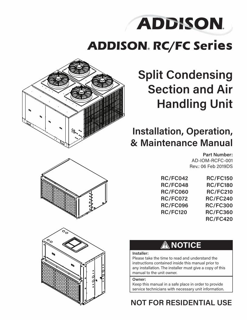
Split Condensing Section and Air
Handling Unit
Installation, Operation, & Maintenance Manual
RC/FC042 RC/FC150RC/FC048 RC/FC180RC/FC060 RC/FC210RC/FC072 RC/FC240RC/FC096 RC/FC300RC/FC120 RC/FC360
RC/FC420
Part Number:AD-IOM-RCFC-001
Rev.: 06 Feb 2019DS
ADDISON® RC/FC Series

This Page is Intentionally Blank

Page 3 of 80
Table of Contents:SECTION 1: Safety Introduction and Labeling Guide Warnings, Dangers, Cautions, and Notices ...................5 Label Placement Guide .......................................................... 6
SECTION 2: Introduction and Pre-Installation 2.1 Description of Operation ..................................................7 2.2 Inspection and Setup ........................................................7 2.3 Condensing Unit Nomenclature Example ............. 8 2.4 Air Handler Section Nomenclature Example ........9
SECTION 3: Installer Responsibility Introduction .................................................................................10 3.1 Corrosive Chemicals .........................................................10 3.2 Required Equipment and Materials .........................10
SECTION 4: Critical Considerations 4.1 Required Clearances .........................................................11 4.2 Unit Placement Considerations .................................13 4.3 Hardware ...............................................................................14 4.4 Ship-With Parts ..................................................................14
SECTION 5: National Standards and Applicable Codes 5.1 Refrigerant Handling Practices ...................................15 5.2 Installation Codes .............................................................15 5.3 Aircraft Hangers .................................................................15 5.4 Parking Structures and Repair Garages ................15 5.5 Electrical ................................................................................15
SECTION 6: Lifting a Split Air Conditioning Unit 6.1 Moving/Lifting The Unit ..................................................16
SECTION 7: Unit Placement .........................................................18
SECTION 8: Ductwork Considerations ...........................................................................19 8.1 Return Air Ductwork .........................................................19 8.2 Discharge Ductwork ........................................................19
SECTION 9: Refrigeration Circuits and Piping 9.1 Refrigerant ............................................................................20 9.2 Components and Configurations .............................20 9.3 Lineset Piping Installation ............................................21 9.4 Refrigerant Oil .....................................................................21 9.5 Hot Gas Reheat Lineset Piping Installation ........26 9.6 Leak Testing and Evacuation .....................................26 9.7 Additional Piping Considerations .............................26
SECTION 10: Unit Electrical 10.1 Wiring and Electrical Connections .........................33 10.2 Disconnect .........................................................................33 10.3 Current Draw ....................................................................33 10.4 Wiring Connections .......................................................33 10.5 Voltage Unbalance.........................................................33 10.5 Low Voltage Wiring .......................................................33
SECTION 11: Electric Heater Packages 11.1 Principle of Operation.....................................................46 11.2 Operating and Safety Controls .................................46 11.3 Wiring ....................................................................................46
SECTION 12: Sequence of Operation 12.1 Unit Configuration ...........................................................49 12.2 Controls Options .............................................................49 12.3 Basic Sequence of Operation ..................................50 12.4 Accessory Controls Options .....................................50
SECTION 13: Start-Up Procedure 13.1 Tools & Supplies Requires ...........................................51 13.2 Pre-Start Checks ............................................................52 13.2 Pre-Start Checklist ........................................................52
SECTION 14: Start-Up Procedures Start-Up Form............................................................................53
SECTION 15: Unit Maintenance Installation Code and Quarterly Inspections .............63 15.1 General ..................................................................................64 15.2 Unit Exterior ......................................................................64 15.3 Direct-Drive Supply and Exhaust Fans ...............64 15.4 Condensing Fans ............................................................64 15.5 Refrigeration Circuit Components .........................64 15.6 Condensate Drain Pan and Drain ..........................65 15.7 Dampers ..............................................................................65 15.8 Electric Heater Wiring and Wiring Conn ............65 15.9 Filters ....................................................................................65
SECTION 16: Replacement Parts .............................................66
SECTION 17: Troubleshooting Supply Fan...................................................................................68 Compressor ................................................................................69 Refrigeration Circuit ................................................................71 Variable Speed Head Pressure Control ........................ 73 Electric Heater ........................................................................... 75
SECTION 18: Addison Warranty ............................................... 76
Revision Guide .................................................................................... 79
RC/FC Series Installation, Operation, and Maintenance Manual
Page 4 of 80
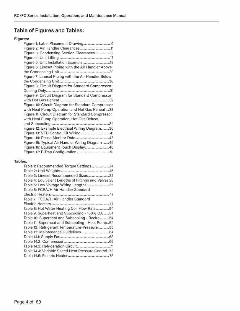
Table of Figures and Tables:Figures: Figure 1: Label Placement Drawing .................................. 6 Figure 2: Air Handler Clearances ......................................11 Figure 3: Condensing Section Clearances ..................12 Figure 4: Unit Lifting ................................................................17 Figure 5: Unit Installation Example ..................................18 Figure 6: Lineset Piping with the Air Handler Above the Condensing Unit ..............................................................29 Figure 7: Lineset Piping with the Air Handler Below the Condensing Unit ..............................................................30 Figure 8: Circuit Diagram for Standard Compressor Cooling Only ................................................................................31 Figure 9: Circuit Diagram for Standard Compressor with Hot Gas Reheat ..............................................................32 Figure 10: Circuit Diagram for Standard Compressor with Heat Pump Operation and Hot Gas Reheat ....33 Figure 11: Circuit Diagram for Standard Compressor with Heat Pump Operation, Hot Gas Reheat, and Subcooling .........................................................................34 Figure 12: Example Electrical Wiring Diagram ..........36 Figure 13: VFD Control Kit Wiring ....................................41 Figure 14: Phase Monitor Data ..........................................43 Figure 15: Typical Air Handler Wiring Diagram ........45 Figure 16: Equipment Touch Display ..............................48 Figure 17: P-Trap Configuration .........................................51
Tables: Table 1: Recommended Torque Settings .......................14 Table 2: Unit Weights ..............................................................16 Table 3: Lineset Recommended Sizes ..........................22 Table 4: Equivalent Lengths of Fittings and Valves 28 Table 5: Low Voltage Wiring Lengths ............................35 Table 6: FCRA/H Air Handler Standard Electric Heaters ........................................................................ 47 Table 7: FCOA/H Air Handler Standard Electric Heaters ........................................................................ 47 Table 8: Hot Water Heating Coil Flow Rate ................54 Table 9: Superheat and Subcooling - 100% OA .......54 Table 10: Superheat and Subcooling - Recirc............54 Table 11: Superheat and Subcooling - Heat Pump ..54 Table 12: Refrigerant Temperature-Pressure ..............55 Table 13: Maintenance Guidelines ...................................64 Table 14.1: Supply Fan.............................................................68 Table 14.2: Compressor .........................................................69 Table 14.3: Refrigeration Circuit .........................................71 Table 14.4: Variable Speed Heat Pressure Control .. 73 Table 14.5: Electric Heater ................................................... 75
RC/FC Series Installation, Operation, and Maintenance Manual

Page 5 of 80
Section 1: Safety Introduction and Labeling Guide:Your Safety is Important to Us!
Please follow and understand the rules and the instructions contained herein carefully. Failure to do so could cause a malfunction of the HVAC equipment, resulting in injury, death and/or property damage.
Throughout this manual, and in specific places on the unit itself, the signal words DANGER, WARNING andCAUTION are used to identify levels of hazard seriousness. NOTICE will be used in areas where there is important information but not hazard related.
• DANGER – Immediate hazards which WILL result in severe personal injury or death.
• WARNING – Hazards or unsafe practices which COULD result in severe personal injury or death.
• CAUTION – Hazards or unsafe practices which COULD result in minor personal injury or product or property damage.
• NOTICE – Information to consider that might result in poor operation, or equipment damage/failure.
DANGER
These instructions, local codes and ordinances and applicable standards that apply to piping, electrical wiring, ventilation, etc. must be thoroughly understood before proceeding with the installation.
Protective gear is to be worn during installation, operation and service in accordance to the Occupational Safety and Hazard Administration (OSHA). Gear must be in accordance to NFPA 70E, latest revision when working with electrical components. Thin sheet metal parts have sharp edges. To prevent injury, the use of work gloves is recommended.
This equipment must be applied and operated under the general concepts of reasonable use and installed using best building practices.
This equipment is not intended for use by persons (including children) with reduced physical, sensory or mental capabilities, or lack of experience and knowledge, unless they have been given supervision or instruction concerning use of the equipment by a person responsible for their safety.
Children should be supervised to ensure that they do not play with the equipment.
To obtain additional copies of the Installation, Operation and Maintenance Manual, please contact Addison.
For detailed information regarding specifications, dimensional drawings, and weight information, contact your local ADDISON® manufacturer’s representative.
DANGER labels will feature white text on a red background.
WARNINGWARNING labels will feature white text on an orange background.
CAUTIONCAUTION labels will feature white text on a yellow background.
NOTICENOTICE labels will feature white text on a black background.
WARNINGImproper installation, service, or maintenance can result in death, injury, or property damage. Read this installation, operation, and maintenance manual thoroughly before installing or servicing this equipment.
Installation must be done by a registered installer/contractor qualified in the installation and service of HVAC equipment.
RC/FC Series Installation, Operation, and Maintenance Manual
Page 6 of 80
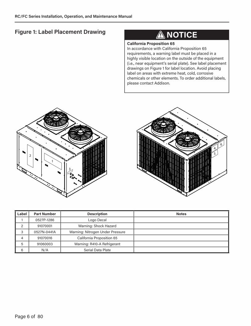
Figure 1: Label Placement Drawing NOTICECalifornia Proposition 65In accordance with California Proposition 65 requirements, a warning label must be placed in a highly visible location on the outside of the equipment (i.e., near equipment’s serial plate). See label placement drawings on Figure 1 for label location. Avoid placing label on areas with extreme heat, cold, corrosive chemicals or other elements. To order additional labels, please contact Addison.
Label Part Number Description Notes1 0527P-1286 Logo Decal2 91070001 Warning: Shock Hazard3 0527N-0441A Warning: Nitrogen Under Pressure4 91070016 California Proposition 655 91060003 Warning: R410-A Refrigerant6 N/A Serial Data Plate
1
2
3
4
5
6
RC/FC Series Installation, Operation, and Maintenance Manual

Page 7 of 80
Section 2: Introduction and Pre-Installation:
2.1 - Description of OperationThe RC/FC Series is a split HVAC system that can operate within a broad range of ambient conditions and introduce ventilation air into a building at neutral conditions. It consists of matched refrigeration and air moving components (system controls, compressor[s], evaporator section, condensing section and fan[s]) designed to treat 100% outside air and/or recirculated air. This system has the ability to filter, cool, heat, and/or dehumidify air.
The unit may be provided with several different options and/or controls to meet various application requirements, including optional hot gas reheat, subcooling/reheat coil (not available on heat pump modes), supplemental heat (electric hot water or steam) and variable air volume delivery. Be sure to read this entire manual before installation and start-up.
2.2 Inspection and SetupAll units are leak-tested, pressure-tested, evacuated, and charged with nitrogen prior to shipment. Immediately upon receipt of the unit, check the electrical supply and characteristics of the unit and verify that they match the electrical supply available. Verify that the specifications on the unit rating plate match your order. Check the unit for any damage that may have occurred during shipment, including internal piping. If any damage is found, file a claim with the transporting agency. Do not refuse shipment. Check the installation location to ensure proper clearances. See Section 3.
Any small options (if so equipped) which do not come attached to the unit (i.e. sensors) will be found inside the condensing unit control enclosure.
If the unit must be temporarily stored (i.e. job site is not ready for installation of the unit), the unit should be set on 4" x 4" (10 cm x 10 cm) pieces of timber on level ground in a protected area. The unit should be covered to be protected from the environment. Indoor air handler sections cannot be stored outside.
WARNINGThis unit contains HFC-(R410A), an azeotropic mixture of R-32 (Difluoromethane) and R-125 (Pentafluoroethane). DO NOT VENT HFC-(R410A) to the atmosphere. The U. S. Clean Air Act requires the recovery of any residual refrigerant. Do not use R-22 service equipment or components on R410A systems.
RC/FC Series Installation, Operation, and Maintenance Manual

Page 8 of 80
2.3 - Condensing Unit Nomenclature Example
Digit: Description: Feature:1 - 2 Product Family RC = Condensing Unit
3 ApplicationO = Dedicated Outdoor AirR = Recirculating
4 Operation TypeA = Air CooledH = Air Source Heat Pump
5 - 7 Nominal Capacity
042 = 3.5 Tons048 = 4.0 Tons060 = 5.0 Tons072 = 6.0 Tons096 = 8.0 Tons120 = 10.0 Tons150 = 12.5 Tons180 = 15.0 Tons210 = 17.5 Tons240 = 20.0 Tons300 = 25.0 Tons360 = 30.0 Tons420 = 35.0 Tons
8 Cabinet Size
A = A CabinetB = B CabinetC = C CabinetD = D CabinetE = E Cabinet
9 Controls
A = ALC, Standard Program, DOASB = ALC, Standard Program, RecirculatingC = ALC, Standard Program, DOAS with LOND = ALC, Standard Program, Recirculating with LONE = Controls by Others, Factory MountedF = Terminal Strip, Controls Provided and Mounted by OthersG = Remote ThermostatH = Compressor Lockout Thermostat
10 Voltage2 = 208/60/33 = 230/60/34 = 460/60/3
11 Vintage H = Current
Note: See unit data plate for specific configuration and options.
RC/FC Series Installation, Operation, and Maintenance Manual
Page 9 of 80
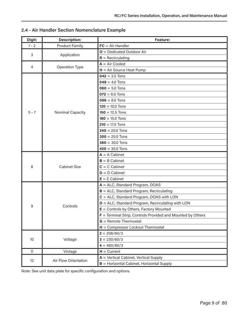
2.4 - Air Handler Section Nomenclature Example
Digit: Description: Feature:1 - 2 Product Family FC = Air Handler
3 ApplicationO = Dedicated Outdoor AirR = Recirculating
4 Operation TypeA = Air CooledH = Air Source Heat Pump
5 - 7 Nominal Capacity
042 = 3.5 Tons048 = 4.0 Tons060 = 5.0 Tons072 = 6.0 Tons096 = 8.0 Tons120 = 10.0 Tons150 = 12.5 Tons180 = 15.0 Tons210 = 17.5 Tons240 = 20.0 Tons300 = 25.0 Tons360 = 30.0 Tons420 = 35.0 Tons
8 Cabinet Size
A = A CabinetB = B CabinetC = C CabinetD = D CabinetE = E Cabinet
9 Controls
A = ALC, Standard Program, DOASB = ALC, Standard Program, RecirculatingC = ALC, Standard Program, DOAS with LOND = ALC, Standard Program, Recirculating with LONE = Controls by Others, Factory MountedF = Terminal Strip, Controls Provided and Mounted by OthersG = Remote ThermostatH = Compressor Lockout Thermostat
10 Voltage2 = 208/60/33 = 230/60/34 = 460/60/3
11 Vintage H = Current
12 Air Flow OrientationA = Vertical Cabinet, Vertical SupplyB = Horizontal Cabinet, Horizontal Supply
Note: See unit data plate for specific configuration and options.
RC/FC Series Installation, Operation, and Maintenance Manual

Page 10 of 80
Section 3: Installer Responsibility:The installer is responsible for the following:
• To install and commission the unit, as well as the electrical supplies, and chilled/hot water (if equiped), in accordance with applicable specifications and codes. Addison recommends the installer contact a local building inspector for guidance.
• To use the information given in a layout drawing and in the manual together with the cited codes and regulations to perform the installation.
• To furnish all needed materials not furnished as standard equipment, including all interconnecting refrigerant piping.
• To plan location of supports.
• To provide access to unit for servicing.
• To provide the owner with a copy of this Installation, Operation and Service Manual.
• To ensure there is adequate air circulation around the unit and to supply air for ventilation and distribution in accordance with local codes.
• To assemble or install any accessories or associated duct work using best building practices.
• To properly size supports and hanging materials.
• To verify that the unit is delivering design airflow by having an air balancing test performed.
• To have refrigerant technician certification per Section 608 of the US Environmental Protection Agency (EPA) Clean Air Act of 1990 or equivalent certification program.
• To have all required equipment to work on direct expansion and/or chilled water air conditioning system.
• Install any ship loose parts.
3.1 Corrosive ChemicalsAddison cannot be responsible for ensuring that all appropriate safety measures are undertaken prior to installation; this is entirely the responsibility of the installer. It is essential that the contractor, the subcontractor, or the owner identifies the presence of combustible materials, corrosive chemicals or halogenated hydrocarbons* anywhere in the premises.
CAUTIONPRODUCT DAMAGE HAZARD Do not use equipment in area containing corrosive materials. Refer to appropriate Material Safety Data Sheets (MSDS). Failure to follow these instructions can result in product damage.
* Halogenated Hydrocarbons are a family of chemical compounds characterized by the presence of halogen elements (fluorine, chlorine, bromine, etc.). These compounds are frequently used in refrigerants, cleaning agents, solvents, etc. If these compounds enter the air supply of the burner, the life span of the unit components will be greatly reduced. An outside air supply must be provided to the burners whenever the presence of these compounds is suspected. Warranty will be invalid if the unit is exposed to halogenated hydrocarbons.
3.2 Required Equipment and MaterialsWhen lifting of the unit is required, the installing contractor is responsible for supplying or arranging for the appropriate lifting equipment so that the unit may be placed in a safe manner.
The qualified installing / service technician is responsible for having the appropriate equipment and materials for the safe installation and start-up of an unit. Tools and materials required to commission the unit include, but are not limited to, the following:
• Various screwdriver types and sizes• Various wrench types and sizes• Drill motor and various drill bits• Voltmeter• Clamp style ammeter• Butyl caulk• Gauges and accessories• Direct expansion and/or chilled water gauges
and accessories.• Refrigerant• Refrigerant oil
RC/FC Series Installation, Operation, and Maintenance Manual

Page 11 of 80
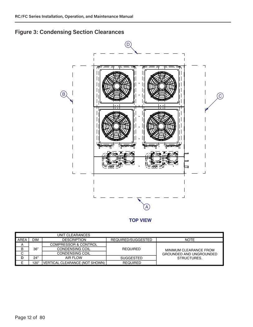
Section 4: Critical Considerations:
4.1 Required ClearancesClearances are the required distances that the unit must be away from objects and other units to allow service access and proper operation of the unit.
TOP VIEW
WHEN REQUIRED CLEARANCEIS NOT AVAILABLE, AN ADJACENT
SUGGESTED CLEARANCE MUST BE MET
UNIT CLEARANCESAREA DIM DESCRIPTION REQUIRED/SUGGESTED NOTE
A36”
BLOWER/COIL ACCESS SUGGESTEDMINIMUM CLEARANCE FROM
GROUNDED AND UNGROUNDEDSTRUCTURES.
B BLOWER/MOTOR ACCESSC BLOWER/MOTOR/BELT ACCESS REQUIREDD 90” COIL REMOVAL*
SUGGESTEDE 36” BLOWER ACCESSF 5” TOP PAN REMOVAL
* NOTE: Horizontal units require vertical clearance over the unit sufficient to remove the air coil. Coil is mounted via clips that can be removed in an upwards direction.
A
B
C
D
E
TOP VIEW
A
B
C
HORIZONTALMODEL
VERTICALMODEL
AIR COIL
AIR COIL
Figure 2: Air Handler Clearances
RC/FC Series Installation, Operation, and Maintenance Manual
Page 12 of 80
TOP VIEW
UNIT CLEARANCESAREA DIM DESCRIPTION REQUIRED/SUGGESTED NOTE
A36”
COMPRESSOR & CONTROLMINIMUM CLEARANCE FROM
GROUNDED AND UNGROUNDEDSTRUCTURES.
B CONDENSING COILC CONDENSING COIL
REQUIRED
D 24” AIR FLOW SUGGESTED
A
B C
D
ED
120” VERTICAL CLEARANCE (NOT SHOWN) REQUIRED
Figure 3: Condensing Section Clearances
RC/FC Series Installation, Operation, and Maintenance Manual

Page 13 of 80
4.1.1 Ventilation ClearancesIn order to help ensure proper operation of an air-source constructed unit, a 24" (61.0 cm) clearance for ventilation must be maintained.
In addition, read and follow the additional ventilation clearance guidelines below:• Do not locate the condensing unit under an overhang
or near a wall/other equipment that will short circuit hot air to the coil intakes.
• Do not locate condensing unit within 10’ (3.0 m) of exhaust fans or flues.
• Do not locate the condensing unit within 48” of another condensing unit to allow air recirculation.
4.2.1 Condensing Unit Placement ConsiderationsLocate the condensing unit as near as possible to the inside air handler section in order to keep connecting refrigerant tubing lengths to minimum and thus minimize loss of capacity due to long lines.
Select a location where external water drainage cannot collect around the condensing unit. Locate the unit so roof runoff water does not pour directly on the condensing unit. Provide gutter or other shielding at roof level. Where snowfall is anticipated, mount the unit so all intakes and discharges are above the maximum snow depth for the area.
When installed at ground level, the condensing unit should be mounted on a level concrete slab which should extend at least 2" (5.1 cm) beyond the unit on all sides. The top of the slab should be 2" (5.1 cm) above the ground level. The depth of the slab below the ground level and its structural design is governed by the type of soil and climatic conditions. The slab must not be in contact with any part of the building wall or foundation. The space between the slab and the building wall prevents the possibility of transmitting vibration to the building. When installing a condensing unit on the roof of a building, the structural members supporting the unit must be sufficiently strong for the weight of the unit and mounting rails.
In areas where there is a risk of hurricane force winds, properly sized “hurricane straps” should be used to secure the unit to the structure or slab it is installed on.
4.2.2 Air Handler Placement ConsiderationsWhen locating the air handlers, make sure there is sufficient free area to allow for adequate airflow to the filters. The air handler must be situated so that it can be serviced and the filters changed. Access panels are located on four sides of vertical units and two sides of horizontal units. However, consideration for the adjustments of the drive belt and motor are important when locating the units adjacent to walls or other units.
The cabinets of these units are well insulated. In most installations, this construction will prevent sweating on the outside of the unit. However, in cases where units are installed above ceilings which are over areas where high humidity conditions are prevalent, it is recommended that an insulated watertight pan with adequate drain connection be constructed and installed under the air handler. This separate drain pan should extend approximately 2” beyond the unit on all sides to ensure collection of any condensate forming on the outside of the cabinet. When this additional pan is used, the unit must not be supported by the pan.
Air handlers are designed for a ducted supply application. Inlet air may be ducted as required.
RC/FC Series Installation, Operation, and Maintenance Manual

Page 14 of 80
Table 1: Recommended Torque Settings
8.8 10.9
8.8 10.9
Bolt Head Grade Marking
Nut Grade Marking
Bolt Size: Grade 2: Grade 5:10-24 27 in-Lb 42 in-Lb1/4-20 65 in-Lb 101 in-Lb5/16-18 11 ft-Lb 17 ft-Lb3/8-16 19 fl-Lb 30 ft-Lb
8.8 10.9
8.8 10.9
Bolt Head Grade Marking
Nut Grade Marking
Bolt Size: Grade 2: Grade 5:M5 6Nm 9NmM6 10Nm 15NmM8 25Nm 35NmM10 50Nm 75NmM12 85Nm 130NmM16 215Nm 315Nm
4.3 HardwareUnless otherwise specified, all hardware (except sheet metal screws) must be torqued to settings from Table 1.
4.4 Ship-With PartsSome options (if selected) may include parts that will require field installation. These parts are included loose with the shipment of the unit, inside the control panel.
• Motor starter – Starter may include phase monitor or VFD
• OA damper• Over the blower electric heater are field-mounted at
least 5” above the air handler discharge• SAT/RH Duct Sensor• DPT Duct Sensor
RC/FC Series Installation, Operation, and Maintenance Manual
Page 15 of 80
Section 5: National Standards and Applicable Codes:
5.1 Refrigerant Handling PracticesThe handling, reclaiming, recovering and recycling of refrigerants as well as the equipment to be used and the procedures to be followed must comply with the national and local codes.
United States: Refer to Federal Clean Air Act - latest revision.Canada: Refer to Canadian Environmental Protection Act - latest revision.
5.2 Installation CodesInstallations must be made in accordance with NFPA 90A - latest revision, Standard for the Installation of Air-Conditioning and Ventilation Systems.
5.3 Aircraft HangarsInstallation in aircraft hangars must be in accordance with the following codes:
United States: Refer to Standard for Aircraft Hangars, NFPA 409 - latest revision.Canada: Refer to Standard CSA B149.1 - latest revision, Natural Gas and Propane Installation Code.
5.4 Parking Structures and Repair GaragesInstallation in garages must be in accordance with the following codes:
United States: Standard for Parking Structures NFPA 88A - latest revision or the Code for Motor Fuel Dispensing Facilities and Repair Garages, NFPA 30A - latest revision.Canada: Refer to CSA B149.1 - latest revision, Natural Gas and Propane Installation Code.
5.5 ElectricalElectrical connection to unit must be in accordance with the following codes:
United States: Refer to National Electrical Code®, NFPA 70 - latest revision. Wiring must conform to the most current National Electrical Code®, local ordinances, and any special diagrams furnished.Canada: Refer to Canadian Electrical Code, CSA C22.1 Part 1 - latest revision.
RC/FC Series Installation, Operation, and Maintenance Manual
Page 16 of 80
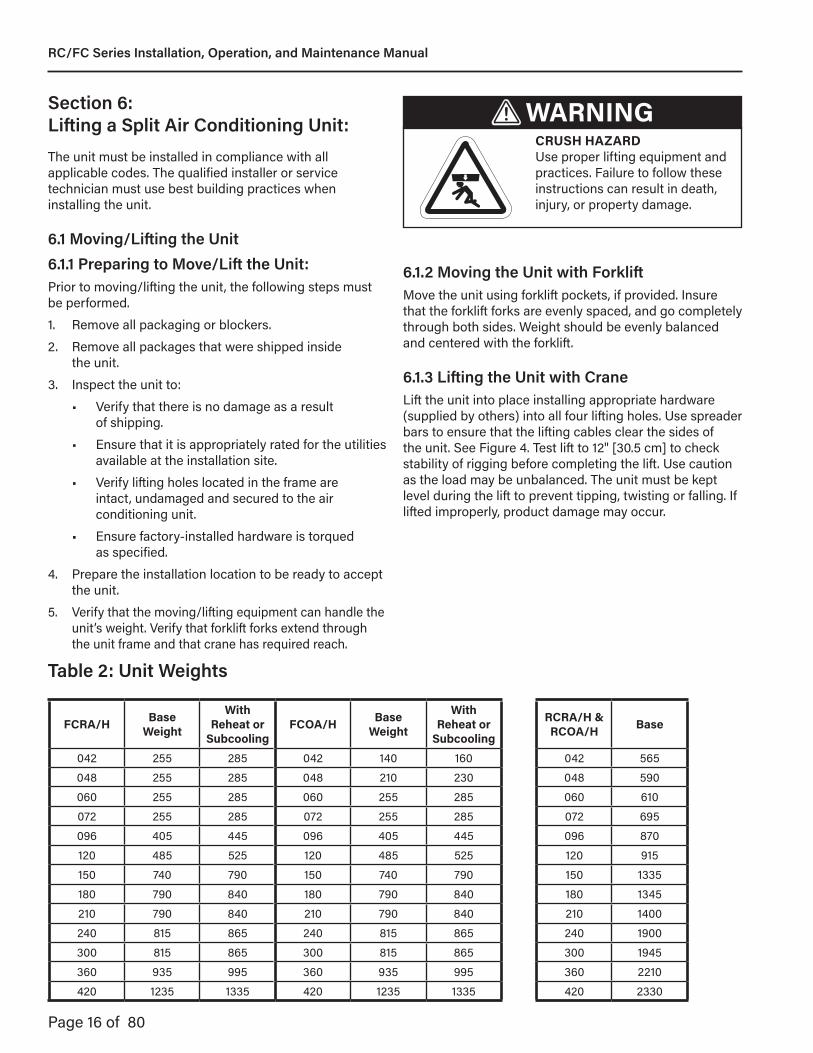
Section 6: Lifting a Split Air Conditioning Unit: WARNING
CRUSH HAZARD Use proper lifting equipment and practices. Failure to follow these instructions can result in death, injury, or property damage.
The unit must be installed in compliance with all applicable codes. The qualified installer or service technician must use best building practices when installing the unit.
6.1 Moving/Lifting the Unit6.1.1 Preparing to Move/Lift the Unit:Prior to moving/lifting the unit, the following steps must be performed.
1. Remove all packaging or blockers.
2. Remove all packages that were shipped inside the unit.
3. Inspect the unit to:
• Verify that there is no damage as a result of shipping.
• Ensure that it is appropriately rated for the utilities available at the installation site.
• Verify lifting holes located in the frame are intact, undamaged and secured to the air conditioning unit.
• Ensure factory-installed hardware is torqued as specified.
4. Prepare the installation location to be ready to accept the unit.
5. Verify that the moving/lifting equipment can handle the unit’s weight. Verify that forklift forks extend through the unit frame and that crane has required reach.
6.1.2 Moving the Unit with ForkliftMove the unit using forklift pockets, if provided. Insure that the forklift forks are evenly spaced, and go completely through both sides. Weight should be evenly balanced and centered with the forklift.
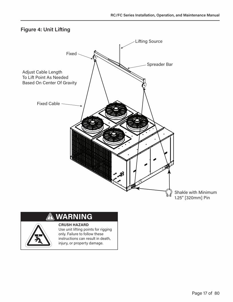
6.1.3 Lifting the Unit with CraneLift the unit into place installing appropriate hardware (supplied by others) into all four lifting holes. Use spreader bars to ensure that the lifting cables clear the sides of the unit. See Figure 4. Test lift to 12" [30.5 cm] to check stability of rigging before completing the lift. Use caution as the load may be unbalanced. The unit must be kept level during the lift to prevent tipping, twisting or falling. If lifted improperly, product damage may occur.
FCRA/H BaseWeight
With Reheat or
SubcoolingFCOA/H Base
Weight
With Reheat or
Subcooling042 255 285 042 140 160048 255 285 048 210 230060 255 285 060 255 285072 255 285 072 255 285096 405 445 096 405 445120 485 525 120 485 525150 740 790 150 740 790180 790 840 180 790 840210 790 840 210 790 840240 815 865 240 815 865300 815 865 300 815 865360 935 995 360 935 995420 1235 1335 420 1235 1335
RCRA/H & RCOA/H Base
042 565048 590060 610072 695096 870120 915150 1335180 1345210 1400240 1900300 1945360 2210420 2330
Table 2: Unit Weights
RC/FC Series Installation, Operation, and Maintenance Manual
Page 17 of 80
Figure 4: Unit Lifting
Fixed
Lifting Source
Spreader Bar
Fixed Cable
Adjust Cable LengthTo Lift Point As NeededBased On Center Of Gravity
Shakle with Minimum1.25” [320mm] Pin
WARNINGCRUSH HAZARD Use unit lifting points for rigging only. Failure to follow these instructions can result in death, injury, or property damage.
RC/FC Series Installation, Operation, and Maintenance Manual
Page 18 of 80
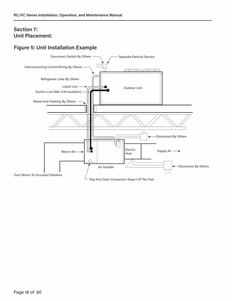
Section 7: Unit Placement:
Return Air
Liquid Line
Suction Line (Min 3/8 Insulation)
Sleeve And Flashing By Others
Disconnect Switch By Others
Interconnecting Control Wiring By Others
Refrigerant Lines By Others
Separate Eletrical Service
Outdoor Unit
Air Handler
Electric Heat
Supply Air
Disconnect By Others
Disconnect By Others
Trap And Drain Connection Slope 1/8” Per FootDuct Return To Occupied Elevation
Figure 5: Unit Installation Example
RC/FC Series Installation, Operation, and Maintenance Manual

Page 19 of 80
Section 8: Ductwork Consideration:The unit has been designed to operate at the specific air volume and external static pressure that was ordered. This static pressure is generated by any additional components that are added to the unit (i.e. ductwork, etc). Additional static pressure beyond that ordered will affect the performance of the air conditioning unit and lessen the air volume that can be delivered.
Proper engineering methods need to be employed when calculating duct and component static pressure (i.e. 2009 ASHRAE Handbook - Fundamentals, Chapter 21).
The system ductwork must comply with Sheet Metal and Air Conditioning Contractors National Association (SMACNA) or any other recognized standards.
It is recommended that flexible duct connections be incorporated into the ductwork design to prevent the transmission of any vibrations, either mechanical or harmonic.
As a general rule, all ducts should have a straight run of at least 3 hydraulic duct diameters immediately before and after the unit before adding any fittings, elbows, restrictions, etc.
Hydraulic duct diameter for round ducts (in inches):Dh = dDh: hydraulic diameterd: round duct inside diameter
Hydraulic duct diameter for rectangular ducts (in inches):Dh = (2*H*W)/(H+W)Dh: hydraulic diameterH: rectangular duct inside heightW: rectangular duct inside width
The unit is not designed to support the weight of ductwork. Ductwork must be constructed in a fashion that is self-supporting.
Depending on the options ordered with the unit, flanges (either external or internal) may be provided to facilitate connection of ductwork. In cases where flanges are not provided, flat surfaces on the exterior skin of the unit are provided to facilitate connection of ductwork.
Neither the flanges nor exterior skin of the unit are capable of supporting the load of the ductwork. Ductwork support must come from the structure itself that the unit is servicing. Ductwork passing through unconditioned spaces must be insulated (including a vapor barrier) to prevent unnecessary energy losses and/or condensation.
8.1 Outside or Return Air DuctworkReturn air ductwork height and width must be no smaller than the unit return air opening height and width.
8.2 Discharge DuctworkDischarge air ductwork height and width must be no smaller that the unit discharge air opening height and width.
RC/FC Series Installation, Operation, and Maintenance Manual

Page 20 of 80
Section 9: Refrigeration Circuits and Piping:
WARNINGEXPLOSION HAZARDSystem contains R-410A refrigerant. Operating pressures may exceed limits of R-22 service equipment. Use proper refrigerant handling practices, tools, and equipment. Failure to follow these instructions can result in death, injury, or property damage.
CAUTIONPRODUCT DAMAGE HAZARD System contains R-410A refrigerant. Operating pressures may exceed limits of R-22 service equipment. Use only R-410A refrigerant and POE 3MAF compressor oil. Verify Failure to follow these instructions can result in equipment damage.
9.1 RefrigerantThis unit utilizes R-410A, a refrigerant with a zero ozone depletion rating, and POE refrigerant oil. Equipment utilizing R-410A refrigerant operates at higher pressures than other typical refrigerants. System components have been sized and pressure switch settings have been adjusted for the system refrigerant flows and higher operating pressures.
The unit has a broad application range. For optimum performance and efficiency, it may be necessary to adjust the refrigerant charge to maintain desired subcooling and superheat at operating temperature extremes.
9.2 Components and ConfigurationsThere are many different refrigeration circuit variations available. Depending on the configuration, the unit may include, but is not limited to, the following components:• Accumulator• Coil
• Evaporator coil• Condenser coil
• Compressor• Standard scroll• Variable Speed Scroll• Digital scroll
• Filter drier• Hot gas bypass valve• Hot gas reheat components
• Check valve• Coil• Solenoid valve (standard) or modulating bypass/
reheat valves (modulating)• Oil separator• Receiver• Refrigerant pressure switches- high and low
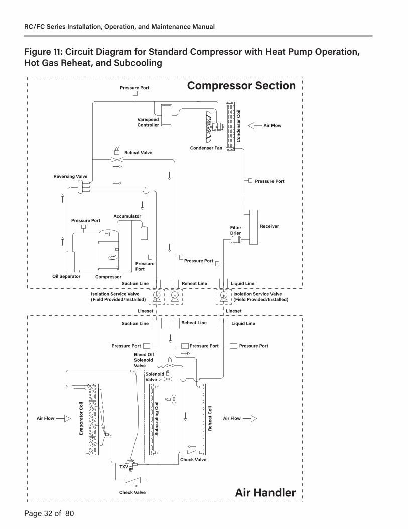
• Non-adjustable• Switchable liquid sub-cooling components
• Coil• Two solenoid valves• Check valve
• Thermal expansion valve (TXV)
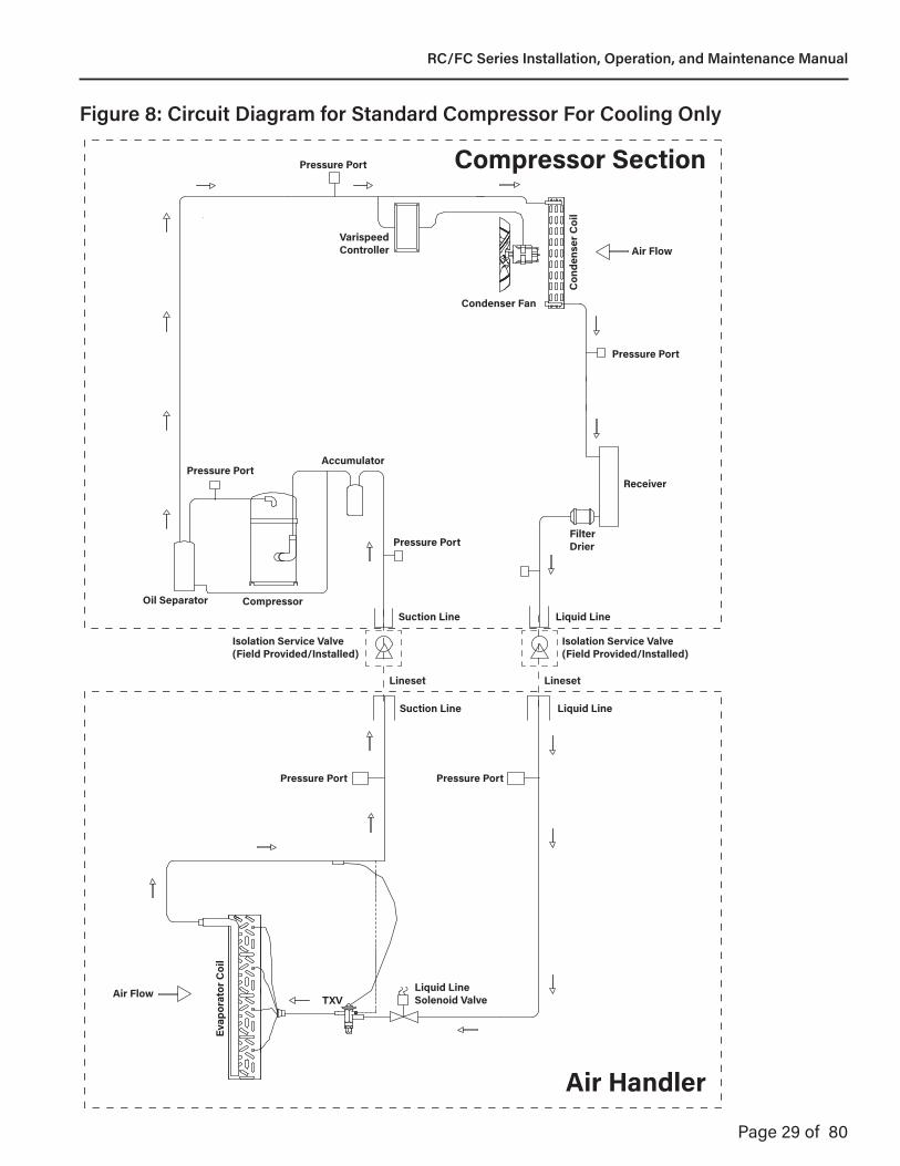
See Figure 7 through Figure 13 for schematics of the most common refrigeration circuit configurations. All schematics illustrate a single-compressor, single-circuit, cooling-only system.• For single-circuit systems with a tandem
compressor, the pair of compressors are mounted on a common base that are used together on a single refrigeration circuit.
• For dual-circuit systems with two independent compressors, the circuitry and components are duplicated for the second circuit.
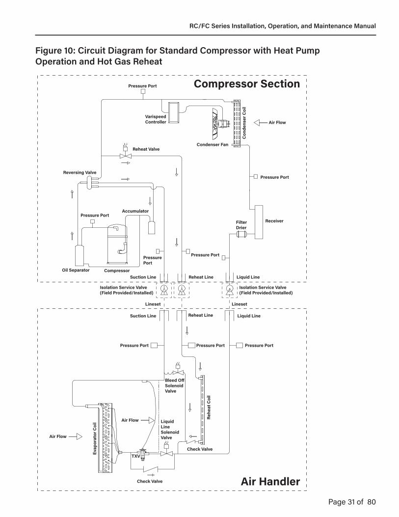
• For heat-pump systems, a reversing valve is included.
WARNINGEXPLOSION HAZARDSystem is shipped with a dry nitrogen charge under pressure, and must be relived before making any connections. Nitrogen is non-polluting and may be vented to the atmosphere.
NOTICEPRODUCT DAMAGE HAZARD Verify compressor and refrigerant oil type of the system before installation. POE and PVE oil cannot be mixed, and will result in equipment damage.
RC/FC Series Installation, Operation, and Maintenance Manual

Page 21 of 80
9.3 Lineset Piping InstallationRead these instructions completely before proceeding with piping.
Prepare to connect the two sections with clean dehydrated refrigeration grade tubing. Recommended line sizes can be found in Tables 3A-3F. In order to assure oil return a velocity of 1,000 FPM must be maintained.
Locations where copper tubing will be exposed to mechanical damage should be avoided. If it is necessary to use such locations, the tubing should be enclosed in rigid or flexible conduit.
Horizontal piping runs should be supported enough to prevent high binding stresses in the tubing. The weight of vertical piping may be either supported with riser clamps bearing on structural members of the building or by a platform at the bottom of the riser.
Supports should be strong enough to handle any load by thermal expansion or contraction of the pipe so that stresses will not be placed on the equipment to which the piping is connected.
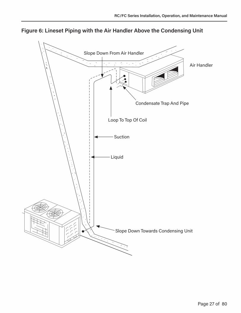
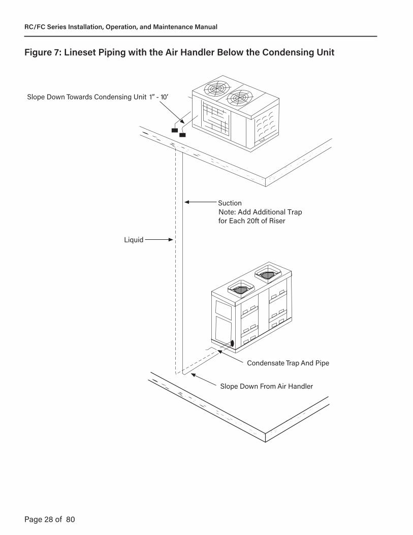
The suction line and both hot gas reheat lines (if included) should be insulated with 5/8” minimum thickness closed cell foamed insulation, to prevent sweating or heat loss. All lines, except the liquid line, must be insulated. However, on installations where the liquid line is exposed to high ambient areas the liquid line must be insulated to prevent sub-cooling loss. Refrigerant lines run underground should be insulated with ¾” minimum thickness closed cell foamed insulation. Suction horizontal lines must be pitched toward the compressor unit, see Figure 6.
When the air handler is installed at a higher elevation than the compressor, provide a vertical loop in the suction line adjacent to the air handler to a point at least to the top of the evaporator coil. Do not insulate the refrigerant or condensate drain lines until all joints in these lines are leak tested.
For long vertical risers in both suction and discharge lines, additional traps are recommended for each full length of pipe (approximately 20 feet) to insure proper oil movement. Purge holding charge from the condensing unit by opening both the high and low pressure gauge ports on the condensing unit and allow holding charge to bleed off to atmospheric pressure.
Drill a 1/16” bleed hole in the cap on the suction line fitting of the air handler (larger of the two fittings) and allow holding charge to reduce to atmospheric pressure.
Remove caps on the suction and liquid lines of the inside section by drilling a small hole in the caps and then apply heat to caps to remove. The caps are soldered to the fittings with soft solder.
Carefully clean the suction line and liquid line fittings on the outside and braze the refrigerant lines to these fittings.Leave gauge port open until all brazing is completed. Low pressure nitrogen purging is recommended while brazing.
9.4 Refrigerant OilAll condensing units come pre-charged with a nominal amount of oil for use with R-410A. Check the unit data plate for the type of oil used in the system.
In split systems, additional oil must be added for refrigerant charges in excess of 20lbs per system. The installing contractor must add an additional ounce of oil for each additional 2lbs of refrigerant added to any system over 20lbs.
Tandem compressors add additional complexity and must be handled with great care being charged. The individual compressors are shipped with an initial oil charge as well as separate sight glasses and oil equalization tubes. During compressor assisted charging, it is important to use only the first stage compressor draw in the refrigerant. Since the tandem compressor has 2 oil pre-charges, the oil added calculation for excess refrigerant starts at 40lbs of R-410A. For tandem compressors, 7 ounces of oil must be added for every 10lbs of R-410A added to the system over 40lbs.
Oil can return to the crankcase for several minutes after the compressor stops. Oil will only flow and equalize between tandem compressors when both compressors are off. The compressor with the higher oil level will only pass surplus oil that is above the mid-point of the sight glass.
Units must have an oil level at, or above, the half-point of the sight glass after being off for a period of 5 minutes or longer, including both compressors in a tandem set.
CAUTIONPRODUCT DAMAGE HAZARD Excessive oil within the system can cause potential issues with operation. The objective is to provide a proper system oil charge that is based on requirements.
RC/FC Series Installation, Operation, and Maintenance Manual
Page 22 of 80
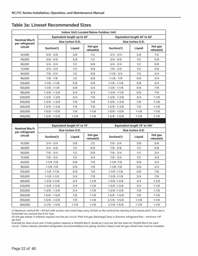
Indoor Unit Located Below Outdoor Unit
Nominal Btu/h per refrigerant
circuit
Equivalent length up to 25’ Equivalent length 26’ to 50’Size inches O.D. Size inches O.D.
Suction(1) Liquid Hot gas reheat(4) Suction(1) Liquid Hot gas
reheat(4)42,000 5/8 - 5/8 3/8 1/2 3/4 - 3/4 3/8 1/248,000 5/8 - 5/8 3/8 1/2 3/4 - 5/8 1/2 5/860,000 3/4 - 3/4 1/2 5/8 3/4 - 3/4 1/2 5/872,000 3/4 - 3/4 1/2 5/8 7/8 - 3/4 1/2 5/884,000 7/8 - 3/4 1/2 5/8 1-1/8 - 3/4 1/2 3/496,000 7/8 - 7/8 1/2 5/8 1-1/8 - 7/8 5/8 3/4120,000 1-1/8 - 1-1/8 5/8 5/8 1-1/8 - 1-1/8 5/8 3/4150,000 1-1/8 - 1-1/8 5/8 3/4 1-1/8 - 1-1/8 5/8 7/8180,000 1-3/8 - 1-3/8 3/4 3/4 1-3/8 - 1-1/8 5/8 7/8220,000 1-3/8 - 1-3/8 3/4 7/8 1-3/8 - 1-3/8 3/4 1-1/8250,000 1-3/8 - 1-3/8 7/8 7/8 1-3/8 - 1-3/8 7/8 1-1/8300,000 1-3/8 - 1-3/8 7/8 7/8 1-5/8 - 1-3/8 7/8 1-1/8350,000 1-5/8 - 1-5/8 7/8 1-1/8 1-5/8 - 1-5/8 1-1/8 1-1/8400,000 1-5/8 - 1-5/8 1-1/8 1-1/8 1-5/8 - 1-5/8 1-1/8 1-1/8
Nominal Btu/h per refrigerant
circuit
Equivalent length 51’ to 75’ Equivalent length 76’ to 100’Size inches O.D. Size inches O.D.
Suction(1) Liquid Hot gas reheat(4) Suction(1) Liquid Hot gas
reheat(4)42,000 3/4 - 3/4 3/8 1/2 7/8 - 3/4 3/8 5/848,000 3/4 - 5/8 1/2 5/8 7/8 - 5/8 1/2 5/860,000 7/8 - 3/4 1/2 5/8 7/8 - 3/4 1/2 3/472,000 7/8 - 3/4 1/2 3/4 7/8 - 3/4 1/2 3/484,000 1-1/8 -7/8 5/8 7/8 1-1/8 -7/8 5/8 3/496,000 1-1/8 -7/8 5/8 7/8 1-1/8 -7/8 5/8 3/4120,000 1-1/8 -1-1/8 5/8 7/8 1-1/8 -1-1/8 5/8 7/8150,000 1-1/8 -1-1/8 3/4 7/8 1-3/8 -1-1/8 3/4 7/8180,000 1-3/8 -1-3/8 3/4 1-1/8 1-3/8 -1-3/8 3/4 1-1/8220,000 1-3/8 -1-3/8 3/4 1-1/8 1-5/8 -1-3/8 3/4 1-1/8250,000 1-3/8 - 1-3/8 3/4 1-1/8 1-3/8 -1-3/8 7/8 1-1/8300,000 1-5/8 - 1-5/8 7/8 1-1/8 1-5/8 - 1-5/8 7/8 1-1/8350,000 1-5/8 - 1-5/8 7/8 1-1/8 2-1/8 - 1-5/8 1-1/8 1-1/8400,000 2-1/8 - 1-5/8 1-1/8 1-1/8 2-1/8 -1-5/8 1-1/8 1-1/8
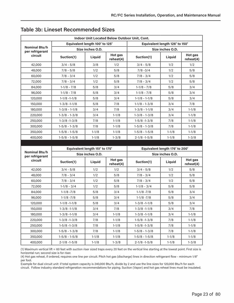
Table 3a: Lineset Recommended Sizes
(1) Maximum vertical lift = 60 feet with suction riser sized traps every 20 feet on the vertical line starting at the lowest point. First size is horizontal run; second size is for riser.(4) Hot gas reheat, if ordered, requires one line per circuit. Pitch hot gas (discharge) lines in direction refrigerant flow - minimum 1/8" per foot.Example for dual circuit unit: if total system capacity is 240,000 Btu/h, divide by 2 and use the line sizes for 120,000 Btu/h for each circuit. Follow industry standard refrigeration recommendations for piping. Suction (Vapor) and hot gas reheat lines must be insulated.
RC/FC Series Installation, Operation, and Maintenance Manual
Page 23 of 80
Indoor Unit Located Below Outdoor Unit, Cont.
Nominal Btu/h per refrigerant
circuit
Equivalent length 100’ to 125’ Equivalent length 126’ to 150’Size inches O.D. Size inches O.D.
Suction(1) Liquid Hot gas reheat(4) Suction(1) Liquid Hot gas
reheat(4)42,000 3/4 - 5/8 3/8 1/2 3/4 - 5/8 1/2 1/248,000 7/8 - 5/8 1/2 5/8 7/8 -3/4 1/2 5/860,000 7/8 - 3/4 1/2 5/8 7/8 - 3/4 1/2 5/872,000 7/8 - 3/4 1/2 5/8 7/8 - 3/4 1/2 5/884,000 1-1/8 - 7/8 5/8 3/4 1-1/8 - 7/8 5/8 3/496,000 1-1/8 - 7/8 5/8 3/4 1-1/8 - 7/8 5/8 3/4120,000 1-1/8 -1-1/8 5/8 3/4 1-1/8 - 1-1/8 5/8 3/4150,000 1-3/8 -1-1/8 5/8 7/8 1-1/8 - 1-3/8 3/4 7/8180,000 1-3/8 - 1-1/8 3/4 7/8 1-3/8 - 1-1/8 3/4 1-1/8220,000 1-3/8 - 1-3/8 3/4 1-1/8 1-3/8 - 1-3/8 3/4 1-1/8250,000 1-3/8 -1-3/8 7/8 1-1/8 1-5/8 -1-3/8 7/8 1-1/8300,000 1-5/8 - 1-3/8 7/8 1-1/8 1-5/8 - 1-3/8 7/8 1-1/8350,000 1-5/8 - 1-5/8 1-1/8 1-1/8 1-5/8 - 1-5/8 1-1/8 1-1/8400,000 1-5/8 - 1-5/8 1-1/8 1-3/8 2-1/8 -1-5/8 1-1/8 1-3/8
Nominal Btu/h per refrigerant
circuit
Equivalent length 151’ to 175’ Equivalent length 176’ to 200’Size inches O.D. Size inches O.D.
Suction(1) Liquid Hot gas reheat(4) Suction(1) Liquid Hot gas
reheat(4)42,000 3/4 - 5/8 1/2 1/2 3/4 - 5/8 1/2 5/848,000 7/8 - 3/4 1/2 5/8 7/8 - 3/4 1/2 5/860,000 7/8 - 3/4 1/2 5/8 7/8 - 3/4 1/2 5/872,000 1-1/8 - 3/4 1/2 5/8 1-1/8 - 3/4 5/8 5/884,000 1-1/8 -7/8 5/8 3/4 1-1/8 -7/8 5/8 3/496,000 1-1/8 -7/8 5/8 3/4 1-1/8 -7/8 5/8 3/4120,000 1-1/8 -1-1/8 5/8 3/4 1-3/8 -1-1/8 5/8 3/4150,000 1-3/8 -1-1/8 3/4 7/8 1-3/8 -1-1/8 3/4 7/8180,000 1-3/8 -1-1/8 3/4 1-1/8 1-3/8 -1-1/8 3/4 1-1/8220,000 1-3/8 -1-3/8 7/8 1-1/8 1-5/8 -1-3/8 7/8 1-1/8250,000 1-5/8 -1-3/8 7/8 1-1/8 1-5/8 -1-3/8 7/8 1-1/8300,000 1-5/8 - 1-3/8 7/8 1-1/8 1-5/8 - 1-3/8 7/8 1-1/8350,000 1-5/8 - 1-5/8 1-1/8 1-1/8 1-5/8 - 1-5/8 1-1/8 1-1/8400,000 2-1/8 -1-5/8 1-1/8 1-3/8 2-1/8 -1-5/8 1-1/8 1-3/8
Table 3b: Lineset Recommended Sizes
(1) Maximum vertical lift = 60 feet with suction riser sized traps every 20 feet on the vertical line starting at the lowest point. First size is horizontal run; second size is for riser.(4) Hot gas reheat, if ordered, requires one line per circuit. Pitch hot gas (discharge) lines in direction refrigerant flow - minimum 1/8" per foot.Example for dual circuit unit: if total system capacity is 240,000 Btu/h, divide by 2 and use the line sizes for 120,000 Btu/h for each circuit. Follow industry standard refrigeration recommendations for piping. Suction (Vapor) and hot gas reheat lines must be insulated.
RC/FC Series Installation, Operation, and Maintenance Manual
Page 24 of 80
Indoor Unit Located Level With, or Above Outdoor Unit
Nominal Btu/h per refrigerant
circuit
Equivalent length up to 25’ Equivalent length 26’ to 50’Size inches O.D. Size inches O.D.
Suction(2) Liquid(3) Hot gas reheat(4) Suction(2) Liquid(3) Hot gas
reheat(4)42,000 3/4 3/8 1/2 3/4 1/2 1/248,000 3/4 1/2 1/2 3/4 1/2 5/860,000 3/4 1/2 5/8 3/4 1/2 5/872,000 3/4 1/2 5/8 7/8 5/8 5/884,000 3/4 5/8 5/8 7/8 5/8 3/496,000 7/8 5/8 5/8 1-1/8 5/8 3/4120,000 7/8 5/8 5/8 1-1/8 5/8 3/4150,000 1-1/8 3/4 3/4 1-1/8 3/4 7/8180,000 1-1/8 3/4 3/4 1-1/8 3/4 7/8220,000 1-1/8 3/4 7/8 1-3/8 7/8 7/8250,000 1-3/8 3/4 7/8 1-3/8 7/8 1-1/8300,000 1-3/8 7/8 7/8 1-3/8 7/8 1-1/8350,000 1-5/8 7/8 1-1/8 1-5/8 1-1/8 1-1/8400,000 1-5/8 1-1/8 1-1/8 1-5/8 1-1/8 1-1/8
Nominal Btu/h per refrigerant
circuit
Equivalent length 51’ to 75’ Equivalent length 76’ to 100’Size inches O.D. Size inches O.D.
Suction(2) Liquid(3) Hot gas reheat(4) Suction(2) Liquid(3) Hot gas
reheat(4)42,000 3/4 1/2 1/2 7/8 1/2 5/848,000 7/8 1/2 5/8 7/8 1/2 5/860,000 7/8 5/8 5/8 1-1/8 1/2 3/472,000 7/8 5/8 3/4 1-1/8 5/8 3/484,000 1-1/8 5/8 7/8 1-1/8 5/8 7/896,000 1-1/8 5/8 7/8 1-1/8 5/8 7/8120,000 1-1/8 3/4 7/8 1-1/8 7/8 7/8150,000 1-1/8 3/4 7/8 1-3/8 3/4 7/8180,000 1-3/8 3/4 1-1/8 1-3/8 3/4 1-1/8220,000 1-3/8 3/4 1-1/8 1-3/8 7/8 1-1/8250,000 1-3/8 1-1/8 1-1/8 1-5/8 7/8 1-1/8300,000 1-5/8 1-1/8 1-1/8 1-5/8 1-1/8 1-1/8350,000 1-5/8 1-1/8 1-1/8 1-5/8 1-1/8 1-1/8400,000 1-5/8 1-1/8 1-1/8 1-5/8 1-1/8 1-1/8
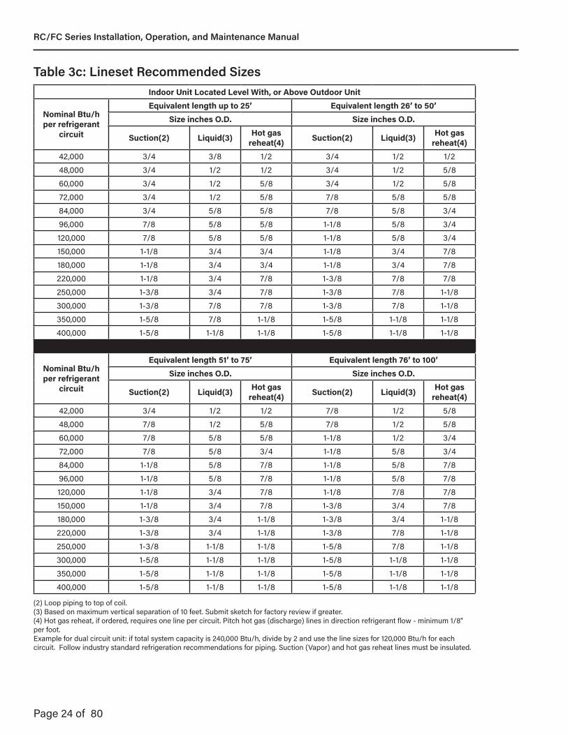
Table 3c: Lineset Recommended Sizes
(2) Loop piping to top of coil.(3) Based on maximum vertical separation of 10 feet. Submit sketch for factory review if greater. (4) Hot gas reheat, if ordered, requires one line per circuit. Pitch hot gas (discharge) lines in direction refrigerant flow - minimum 1/8" per foot.Example for dual circuit unit: if total system capacity is 240,000 Btu/h, divide by 2 and use the line sizes for 120,000 Btu/h for each circuit. Follow industry standard refrigeration recommendations for piping. Suction (Vapor) and hot gas reheat lines must be insulated.
RC/FC Series Installation, Operation, and Maintenance Manual
Page 25 of 80
Indoor Unit Located Level With, or Above Outdoor Unit
Nominal Btu/h per refrigerant
circuit
Equivalent length 100’ to 125’ Equivalent length 126’ to 150’Size inches O.D. Size inches O.D.
Suction(2) Liquid(3) Hot gas reheat(4) Suction(2) Liquid(3) Hot gas
reheat(4)42,000 3/4 1/2 1/2 3/4 1/2 5/848,000 7/8 1/2 5/8 7/8 1/2 5/860,000 7/8 1/2 5/8 7/8 1/2 5/872,000 7/8 5/8 5/8 7/8 5/8 5/884,000 7/8 5/8 3/4 7/8 5/8 3/496,000 1-1/8 5/8 3/4 1-1/8 5/8 3/4120,000 1-1/8 7/8 3/4 1-1/8 3/4 3/4150,000 1-3/8 3/4 7/8 1-3/8 3/4 7/8180,000 1-1/8 3/4 7/8 1-1/8 7/8 1-1/8220,000 1-3/8 7/8 1-1/8 1-3/8 7/8 1-1/8250,000 1-3/8 7/8 1-1/8 1-5/8 7/8 1-1/8300,000 1-5/8 1-1/8 1-1/8 1-5/8 1-1/8 1-1/8350,000 1-5/8 1-1/8 1-1/8 1-5/8 1-1/8 1-1/8400,000 1-5/8 1-1/8 1-3/8 1-5/8 1-1/8 1-3/8
Nominal Btu/h per refrigerant
circuit
Equivalent length 151’ to 175’ Equivalent length 176’ to 200’Size inches O.D. Size inches O.D.
Suction(2) Liquid(3) Hot gas reheat(4) Suction(2) Liquid(3) Hot gas
reheat(4)42,000 3/4 1/2 1/2 3/4 1/2 1/248,000 7/8 1/2 5/8 7/8 1/2 5/860,000 7/8 1/2 5/8 7/8 5/8 5/872,000 7/8 5/8 5/8 7/8 3/4 5/884,000 1-1/8 5/8 3/4 1-1/8 5/8 3/496,000 1-1/8 5/8 3/4 1-1/8 3/4 3/4120,000 1-1/8 3/4 3/4 1-1/8 3/4 3/4150,000 1-3/8 3/4 7/8 1-3/8 7/8 7/8180,000 1-3/8 7/8 1-1/8 1-3/8 7/8 1-1/8220,000 1-5/8 7/8 1-1/8 1-5/8 7/8 1-1/8250,000 1-5/8 7/8 1-1/8 1-5/8 7/8 1-1/8300,000 1-5/8 1-1/8 1-1/8 1-5/8 1-1/8 1-1/8350,000 1-5/8 1-1/8 1-1/8 1-5/8 1-1/8 1-1/8400,000 1-5/8 1-1/8 1-3/8 1-5/8 1-1/8 1-3/8
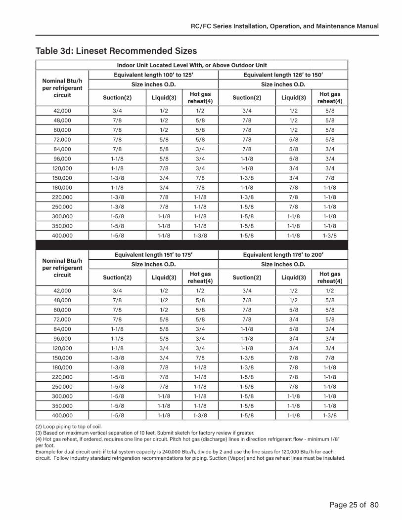
Table 3d: Lineset Recommended Sizes
(2) Loop piping to top of coil.(3) Based on maximum vertical separation of 10 feet. Submit sketch for factory review if greater. (4) Hot gas reheat, if ordered, requires one line per circuit. Pitch hot gas (discharge) lines in direction refrigerant flow - minimum 1/8" per foot.Example for dual circuit unit: if total system capacity is 240,000 Btu/h, divide by 2 and use the line sizes for 120,000 Btu/h for each circuit. Follow industry standard refrigeration recommendations for piping. Suction (Vapor) and hot gas reheat lines must be insulated.
RC/FC Series Installation, Operation, and Maintenance Manual

Page 26 of 80
9.5 Hot Gas Reheat Lineset Piping InstallationLocate the hot gas reheat connection line(s) (factory installed) at the indoor unit. Locate the hot gas reheat circuit connection in the condensing unit. The hot gas reheat valve and solenoid is factory installed.
Size the piping between the evaporator and condenser for a minimum pressure drop. See Table 3 for recommended line size.
The piping should be free draining to the evaporator connection to ensure oil return to the compressor.
Connect the piping with clean, dehydrated refrigerant grade tubing. Use standard industry practices to install the refrigerant line.
9.6 Leak Testing and EvacuationCharge system with R-410A trace gas and dry nitrogen. Pressurize to 150 PSIG.
Check inside unit, and interconnecting piping with suitable leak detector. Relieve testing charge and connect a good vacuum pump to the gauge connections.
Do not open any other valves at this time. Connect a micron gauge to the vacuum pump. A deep vacuum of at least 500 microns is required.
Wait 15 minutes, if there is no rise on the micron gauge the system is sealed.
9.7 Additional Piping Considerations9.7.1 LeaksLeaks occur at incorrectly made joints. Very small scratches or particles of dirt in a joint can cause a refrigerant leak. The leak may be so small that it is difficult to detect on a Halide leak detector. Leaks can develop even years after the joint is made unless flux and solder specifically developed for refrigerant work are used. Any improper made joint will cause trouble in time, as it will eventually leak enough refrigerant to reduce capacity of the system.
9.7.2 MoistureMoisture in the refrigeration system will combine with fluorine in the refrigerant and form hydrofluoric acid which will corrode and pit the system. Hydrofluoric acid also decomposes the compressor lubrication oil causing sludge. Great care should be exercised in keeping moisture out of the refrigeration system when installing tubing, because an extremely small amount can cause trouble. For this reason, except on large sizes, only refrigeration grade, seamless annealed, sealed copper tubing should be used. This tubing is available at refrigeration supply stores and has been dehydrated, cleaned inside and sealed at each end. Exposure of the inside of the tubing to the atmosphere must be kept to minimum. Do not use tubing that has been exposed.
9.7.3 DirtDirt and metal chips must be kept out of the refrigeration system, since they will accumulate at strainers and clog them, restricting the flow of refrigerant.
Equivalent Length in Feet of Pipe for Valves and FittingsTubing Size: O.D.
Short Radius Elbow
Long Radius Elbow
Tee Line Tee Branch
Angle Valve
1/2 1.6 1.0 1.0 3.1 8.35/8 1.9 1.2 1.2 3.6 10.43/4 2.1 1.4 1.4 4.2 12.57/8 2.4 1.6 1.6 4.8 14.6
1-1/8 3.0 2.0 2.0 6.0 18.81-3/8 3.6 2.4 2.4 7.2 22.91-5/8 4.2 2.8 2.8 8.4 27.12-1/8 5.3 3.5 3.6 10.7 35.4
Table 4: Equivalent Lengths of Fittings and Valves
RC/FC Series Installation, Operation, and Maintenance Manual
Page 27 of 80
Slope Down From Air Handler
Condensate Trap And Pipe
Air Handler
Loop To Top Of Coil
Suction
Liquid
Slope Down Towards Condensing Unit
Figure 6: Lineset Piping with the Air Handler Above the Condensing Unit
RC/FC Series Installation, Operation, and Maintenance Manual
Page 28 of 80
Slope Down From Air Handler
Condensate Trap And Pipe
Suction
Liquid
Slope Down Towards Condensing Unit 1” - 10’
Note: Add Additional Trapfor Each 20ft of Riser
Figure 7: Lineset Piping with the Air Handler Below the Condensing Unit
RC/FC Series Installation, Operation, and Maintenance Manual
Page 29 of 80
Figure 8: Circuit Diagram for Standard Compressor For Cooling Only
Oil Separator Compressor
Pressure Port
Condenser Fan
Receiver
VarispeedController
Con
dens
er C
oil
Air Flow
Pressure Port
Pressure Port
Suction Line Liquid Line
Suction Line Liquid Line
Pressure Port
Pressure PortPressure Port
Air Flow
Evap
orat
or C
oil
TXV
Isolation Service Valve(Field Provided/Installed)
Isolation Service Valve(Field Provided/Installed)
LinesetLineset
Air Handler
Compressor Section
Accumulator
FilterDrier
Liquid LineSolenoid Valve
RC/FC Series Installation, Operation, and Maintenance Manual

Page 30 of 80
Figure 9: Circuit Diagram for Standard Compressor with Hot Gas Reheat
Oil Separator Compressor
Pressure Port
Liquid LineSolenoid Valve
FilterDrier
Condenser Fan
Receiver
VarispeedController
Con
dens
er C
oil
Air Flow
Pressure Port
Pressure Port
Suction Line Liquid Line
Suction Line Liquid Line
PressurePort
Pressure PortPressure Port
Air Flow
Evap
orat
or C
oil
TXV
Isolation Service Valve(Field Provided/Installed)
Isolation Service Valve(Field Provided/Installed)
LinesetLineset
Air Handler
Compressor Section
Accumulator
Air Flow
Check Valve
Rehe
at C
oil
Bleed O�SolenoidValve
Reheat Line
Pressure Port
Reheat Valve
Pressure Port
Reheat Line
RC/FC Series Installation, Operation, and Maintenance Manual
Page 31 of 80
Figure 10: Circuit Diagram for Standard Compressor with Heat Pump Operation and Hot Gas Reheat
Oil Separator Compressor
Pressure Port
LiquidLineSolenoidValve
FilterDrier
Condenser Fan
Receiver
VarispeedController
Con
dens
er C
oil
Air Flow
Pressure Port
Pressure Port
Suction Line Liquid Line
Suction Line Liquid Line
PressurePort
Pressure PortPressure Port
Air Flow
Evap
orat
or C
oil
TXV
Isolation Service Valve(Field Provided/Installed)
Isolation Service Valve(Field Provided/Installed)
LinesetLineset
Air Handler
Compressor Section
Accumulator
Check Valve
Air Flow
Check Valve
Rehe
at C
oil
Bleed O�SolenoidValve
Reheat Line
Pressure Port
Reheat Valve
Pressure Port
Reheat Line
Reversing Valve
RC/FC Series Installation, Operation, and Maintenance Manual
Page 32 of 80
Figure 11: Circuit Diagram for Standard Compressor with Heat Pump Operation, Hot Gas Reheat, and Subcooling
Oil Separator Compressor
Pressure Port
SolenoidValve
FilterDrier
Condenser Fan
Receiver
VarispeedController
Con
dens
er C
oil
Air Flow
Pressure Port
Pressure Port
Suction Line Liquid Line
Suction Line Liquid Line
PressurePort
Pressure PortPressure Port
Air Flow
Evap
orat
or C
oil
TXV
Isolation Service Valve(Field Provided/Installed)
Isolation Service Valve(Field Provided/Installed)
LinesetLineset
Air Handler
Compressor Section
Accumulator
Check Valve
Air Flow
Check Valve
Rehe
at C
oil
Bleed O�SolenoidValve
Reheat Line
Pressure Port
Reheat Valve
Pressure Port
Reheat Line
Reversing Valve
Subc
oolin
g C
oil
RC/FC Series Installation, Operation, and Maintenance Manual
Page 33 of 80
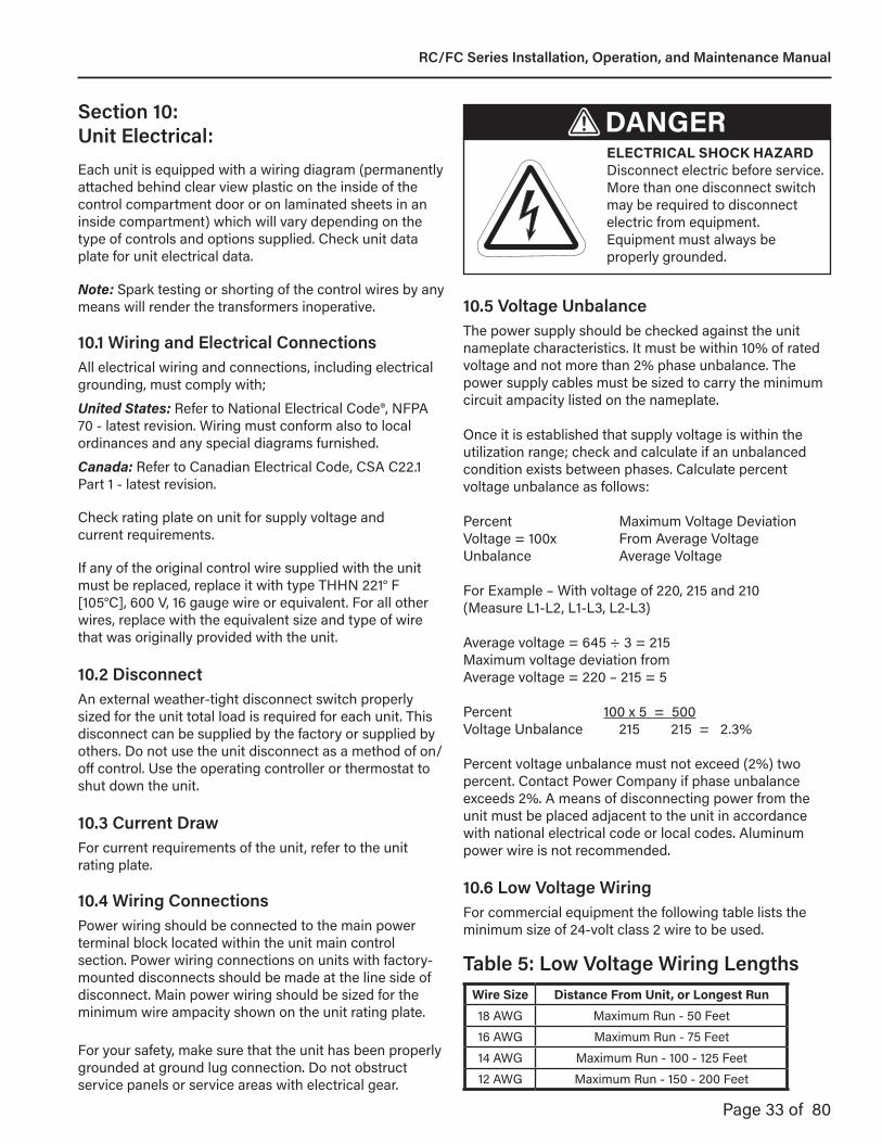
DANGERELECTRICAL SHOCK HAZARDDisconnect electric before service. More than one disconnect switch may be required to disconnect electric from equipment. Equipment must always be properly grounded.
Section 10: Unit Electrical:Each unit is equipped with a wiring diagram (permanently attached behind clear view plastic on the inside of the control compartment door or on laminated sheets in an inside compartment) which will vary depending on the type of controls and options supplied. Check unit data plate for unit electrical data.
Note: Spark testing or shorting of the control wires by any means will render the transformers inoperative.
10.1 Wiring and Electrical ConnectionsAll electrical wiring and connections, including electrical grounding, must comply with;
United States: Refer to National Electrical Code®, NFPA 70 - latest revision. Wiring must conform also to local ordinances and any special diagrams furnished.
Canada: Refer to Canadian Electrical Code, CSA C22.1 Part 1 - latest revision.
Check rating plate on unit for supply voltage and current requirements.
If any of the original control wire supplied with the unit must be replaced, replace it with type THHN 221° F [105°C], 600 V, 16 gauge wire or equivalent. For all other wires, replace with the equivalent size and type of wire that was originally provided with the unit.
10.2 DisconnectAn external weather-tight disconnect switch properly sized for the unit total load is required for each unit. This disconnect can be supplied by the factory or supplied by others. Do not use the unit disconnect as a method of on/off control. Use the operating controller or thermostat to shut down the unit.
10.3 Current DrawFor current requirements of the unit, refer to the unit rating plate.
10.4 Wiring ConnectionsPower wiring should be connected to the main power terminal block located within the unit main control section. Power wiring connections on units with factory-mounted disconnects should be made at the line side of disconnect. Main power wiring should be sized for the minimum wire ampacity shown on the unit rating plate.
For your safety, make sure that the unit has been properly grounded at ground lug connection. Do not obstruct service panels or service areas with electrical gear.
10.5 Voltage UnbalanceThe power supply should be checked against the unit nameplate characteristics. It must be within 10% of rated voltage and not more than 2% phase unbalance. The power supply cables must be sized to carry the minimum circuit ampacity listed on the nameplate.
Once it is established that supply voltage is within the utilization range; check and calculate if an unbalanced condition exists between phases. Calculate percent voltage unbalance as follows:
Percent Maximum Voltage Deviation Voltage = 100x From Average Voltage Unbalance Average Voltage
For Example – With voltage of 220, 215 and 210(Measure L1-L2, L1-L3, L2-L3)
Average voltage = 645 ÷ 3 = 215 Maximum voltage deviation from Average voltage = 220 – 215 = 5
Percent 100 x 5 = 500Voltage Unbalance 215 215 = 2.3%
Percent voltage unbalance must not exceed (2%) two percent. Contact Power Company if phase unbalance exceeds 2%. A means of disconnecting power from the unit must be placed adjacent to the unit in accordance with national electrical code or local codes. Aluminum power wire is not recommended.
10.6 Low Voltage WiringFor commercial equipment the following table lists the minimum size of 24-volt class 2 wire to be used.
Wire Size Distance From Unit, or Longest Run18 AWG Maximum Run - 50 Feet16 AWG Maximum Run - 75 Feet14 AWG Maximum Run - 100 - 125 Feet12 AWG Maximum Run - 150 - 200 Feet
Table 5: Low Voltage Wiring Lengths
RC/FC Series Installation, Operation, and Maintenance Manual

Page 34 of 80
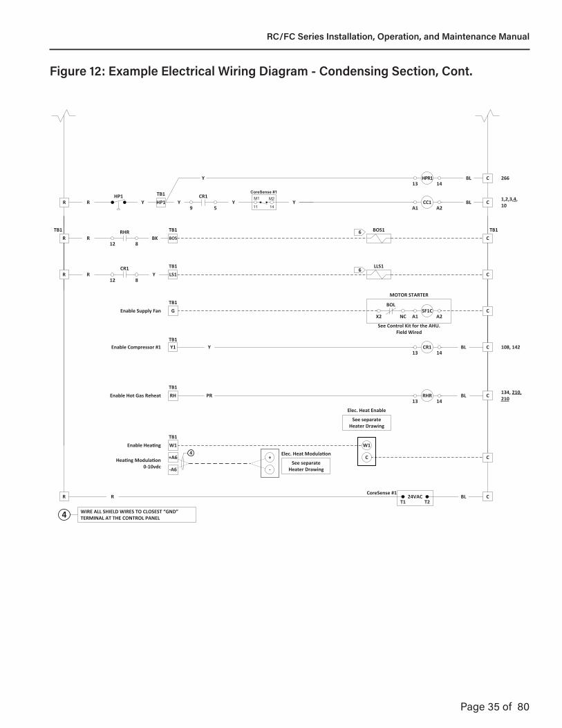
Figure 12: Example Electrical Wiring Diagram - Condensing Section
PDB
PM
CS
CS
CCH1
G-14
1.
EGB
L3
L2
L1
EGB
MSP-CC1
L3 T3
L2 T2
L1 T1
L3
L2
L1
T3
T2
T1
CM1T3
T2
T1
R-14
BK-14
0V 208V
230V
460V
H4 H3 H2 H1
CURRENT SENSOR
F3
F13 (L1)
CC1
CC1-A1
CONNECT TO TERMINAL H1 FOR UNITS RATED 460V.CONNECT TO TERMINAL H2 FOR UNITS RATED 230V.CONNECT TO TERMINAL H3 FOR UNITS RATED 208V.SEE 575/600V TRANSFORMER FOR CORRECT WIRING CONNECTIONS ON UNITS RATED 575V.
OF1VFD
OFM1 G-14
MSP-OF1VFD
BL-12
BK-12
L3 T3
L2 T2
L1 T1
R-12
BL-12
BK-12
R-12
BL-14
BK-14
R-14
UL1
VL2
WL3
G-14
MSP-OF1
L3 T3
L2 T2
L1 T1
OFM2 G-14BL-14
BK-14
MSP-OF2
L3 T3
L2 T2
L1 T1
BL-14
BK-14
R-14
BL-14
BK-14
R-14
CoreSense #1 L3L1 L2
5 (L3)F2
4 (L2)
T3
Line Voltage
96 VA CLASS 2
50/60HZ
F9
F10
R-14White 0-10vdc
OUTDOOR FAN MOTOR VFD (OF1VFD)CONTROL TERMINAL STRIP
CC1-A1
Red +12-30VDC
OF1VFD
24V
2
1
DI23
DI1
AI1
0V7
6
Black Common
R
YY
R-4 R-4 R-4
BL-4 BL-4 BL-4
BK-4 BK-4 BK-4
TB1
24VTB4
G-14
TB4K3 K4
PM AUX
NO CR
PM
T150/60HZ
115V
24V
0V
X3X2XFX1
G-14
R-14
R-14R-14
BL-14
CB
TB2 TB2
PM
8 1
7
7 6Remove jumper when field installed safeties are used
R-14CBK BLJ2J1
RC/FC Series Installation, Operation, and Maintenance Manual
Page 35 of 80
HP1TB1CC1Enable Compressor #1 Y1 BL
A2A1
1,2,3,4, 10Y
CR1
9
HP1R YR
5
HPR11413
BL 266
TB1HP1
Y
Y Y YY
CoreSense #1M1 M2
11 14Y
TB1BOS1TB1
TB1
TB1
TB1
CoreSense #1
RHRR
TB1BOSBK
12 8
See Control Kit for the AHU.Field Wired
MOTOR STARTER
TB1
TB1
TB1
LLS1R YR
CR1
12 8
SF1CEnable Supply Fan G
Enable Hot Gas Reheat RH PR
A2
RHR1413
LS16
6
BOL
X2 NC A1
BL
24VACT2T1
R CBLR
TB1Enable Compressor #1 Y1 CR1
1413Y BL 108, 142
Elec. Heat Enable
TB1
See separate Heater Drawing
Enable Heating W1 W1
CElec. Heat Modulation
See separate Heater Drawing
+A6
-A6
Heating Modulation 0-10vdc
+
-
4C
C
C
C
C
R C
134, 210, 210
WIRE ALL SHIELD WIRES TO CLOSEST “GND” TERMINAL AT THE CONTROL PANEL4
C
C
Figure 12: Example Electrical Wiring Diagram - Condensing Section, Cont.
RC/FC Series Installation, Operation, and Maintenance Manual

Page 36 of 80
Not IncludedZS Room Sensor
Off OnAuto
Universal Input Mode Select
Aux Power Out
Power
Off On
Port 1
RnetGnd
RNET+
RNET-
+12V
UO-8
UO-7
UO-6
UO-5
Gnd 8UO-4
+ 7
Gnd 6UO-3
+ 5
Gnd 4UO-2
+ 3
Gnd 2UO-1
+ 1
Gnd 8
+ 7
Gnd 6
+ 5
Gnd 4
+ 3
Gnd 2
+ 1
UI-8
UI-7
UI-6
UI-5
8 GndUI-4
7 +
6 GndUI-3
5 +
4 GndUI-2
3 +
2 GndUI-1
1 +
UI-12
UI-11
UI-10
UI-9
Rnet Local Access
GndRnet+Rnet-+12VSense
8 Gnd
7 +
6 Gnd
5 +
4 Gnd
3 +
2 Gnd
1 +
8 Gnd
7 +
6 Gnd
5 +
4 Gnd
3 +
2 Gnd
1 +
Gnd
24VAC
0 5
0 5
12
34
56
78
10's
1'sModule Address
NET +
NET -
Shield
Port 1 BT485
Port 2a BT485
485 Port 1ARC-156
2 Wire
EIA-485
4 Wire
EIA-232
Port 2a
XNET +
XNET -
Gnd
Port 2a
NET +
NET -
n/c
n/c
Signal Ground
Tx +
Tx -
Rx +
Rx -
Tx
Rx
DTR
DCD
2 wire 4 wire EIA-232
mAThermistor/Dry Contact/
RTD
Volts
Off
2 1
Assigned Default
On Off
BAS Port
IP Addr
Enhanced Access Port 2a
BACn
et
BAS Port SettingsBAUD 4 5 Protocols 6 7 89600 Off Off MSTP (m) Off Off Off19.2K Off On MSTP (s) On Off Off38.4K On Off PTP Off On Off76.8K On On N2 On On Off
Modbus Off Off OnLon SLTA On Off OnLon Option Off On On
Fuse
24VDC
200mA maximum
100 LAN LINK
10/100 BaseT Ethernet Port E1
Xnet Expansion
See BAS Table Below
+ 3V
GndExternal Battery
Ext. Batt.Int. Batt.
0-10Vdc0-20 mA Relay Pot
UO-1
UO-2
UO-3
UO-4
UO-5
UO-6
UO-7
UO-8
Set Pot Full CW
Port 2b
Format
I/O PRO 812uCONTROLLER
SEE TB4 ON UNIT WIRING DIAGRAM
R
TB4
BL
FACTORY WIRINGFIELD WIRINGTERMINAL BOARD
SYMBOL LEGEND
USE 18 AWG WIRE MINIMUM. TO MINIMIZE INTERFERENCE PROBLEMS: USE SHIELDED WIRE ON ALL ANALOG INPUTS
AND OUPUTS. DO NOT RUN 0-10 VOLT DC SIGNAL WIRING IN THE SAME CONDUIT AS LINE VOLTAGE WIRING OR WITH WIRING THAT SWITCHES HIGHLY INDUCTIVE LOADS SUCH AS CONTACTOR AND RELAY COILS. GROUND ONE END OF THE DRAIN (SHIELD) WIRE.
WHEN 0-10 VOLT DC SIGNAL WIRING MUST CROSS CLOSE TO CABLE OR NONMETALLIC CONDUIT CONTAINING LINE VOLTAGE WIRING OR WIRING THAT SWITCHES HIGHLY INDUCTIVE LOADS, IT MUST CROSS PERPENDICULAR (90 DEGREES) TO IT.
KEEP THE 0-10 VOLT DC SIGNAL WIRING AS SHORT AS POSSIBLE.
LON
12
Port 2bECHELO
N
LonWorks Card (optional)
FOR FIELD: BAS OR EMS CONNECTION
3V Litium BatteryCR-123A
- +
Error Codes:Chase = OK0 = Download Required1 = Control Program Error2 = RAM full3 = Comm set-up error4 = System error8 = FormattingBlinking Dot = ‘Run’
DO NOT APPLY 24V AC TO UNIVERSAL OUTPUTSExternal 24VDC relay coil only
24V ACR
TB-A
GND
GND
24VDC
USE SHIELDED WIRE FOR ALL ANOLOG INPUTS
WIRE ALL SHIELD WIRES TO CLOSEST TB-A or TB-D “GND” TERMINAL AT THE CONTROL PANEL4
24VDC
4
4
R
Heat Modulating
BKBK
R
R
BKBK
R
-A6
+A6TB1
4
2temp
sensorVout
comV inpw
r
OA-T/RH
BK
G
DxLAT1
R
BK
DxLAT1: INSTALL AFTER DX COIL #1 UPSTREAM OF REHEAT COIL
SA-T/RHField install
and wire 1temp
sensorVout
comV inpw
r
4
Note: THE SUPPLY/DISCHARGE AIR TEMPERATURE/RELITIVE HUMIDITY (SA-T/RH) IS FACTORY SUPPLIED FOR FIELD INSTALLATION IN SUPPLY AIR DUCT. SENSOR MUST BE INSTALLED DOWNSTREAM OF HEATER (IF USED) WHERE IT CANNOT “SEE” ANY HEATING ELEMENTS AND WHERE SUFFICIENT MIXING OF DISCHARGE AIR OCCURS. USE 18 AWG SHIELDED WIRE. DO NOT RUN SENSOR WIRING IN THE SAME CONDUIT AS LINE VOLTAGE WIRING OR WITH WIRING THAT SWITCHES HIGHLY INDUCTIVE LOADS SUCH AS CONTACTOR AND RELAY COILS.
1
Install OA-T/RH at the condensing unit, sensing the ambient temp/humidity.
2
W
4
SENSORS DESCRIPTIONCFI Clogged Filter Indicator
DPT-260 Differential Pressure TransmitterSAT Supply Air Temperature Sensor
OA-T/RH Outdoor Air Temp/Relative Humidity SensorSA-RH Supply Air Relative Humidity
ZS Zone Temperature Sensor - StandardCC1-CS, CC2-CS Compressor #1 & #2 Current Sensor
DxLAT Dx Leaving Air Temperature SensorWM-CS Wheel Motor Current Sensor
SF-APS, EF-APS Supply Fan / Exhaust Fan Air Press. SwitchWFR Water Flow Relay
LP1, LP2 Low Pressure Switch, Ckt. #1 & #2SD Smoke Detector
K3
K4
5
9
Unloader Relay #1
R
PRUnloader #1
U1
RTB1
GY
PR 14
13
WARNING!!!DO NOT leave dip
switch #1 “ON”. This will result in loss of
BACview and network communications.
HGRH(MRC)
-A4
+A4TB1
Gnd
RNET
+RN
ET-
+12V
Gnd
Rnet
+Rn
et-
+12V
Sens
e
BlackRed
G
W
Green
EQUIPMENTTOUCH
Gnd
Rnet+Rnet-
+24VAC
RedBlack
White
FIELD INSTALL
4
K3
K4
-12V
Rnet+
Rnet-
+12V
TB4
TB5
To Wall Mount theEquipment Touch removethe factory installed cable
and wire +24VAC to TB4 “K3”and wire Gnd to TB4 “K4”. Ifthere is a ZS sensor installedwire Rnet+ and Rnet- to theZS sensor Rnet+ and Rnet –
terminals, otherwise wire toTB5 Rnet+ and Rnet-
BK
G
W
R
4
BK
R
Equipment TouchConnector
(Blue)
WhiteGreen
FOR FIELD: BACNET
CONNECTION
Figure 12: Example Electrical Wiring Diagram - Condensing Section, Cont.
RC/FC Series Installation, Operation, and Maintenance Manual

Page 37 of 80
Heating Enable
Y
R
W
SEE UNIT 24V CONTROL TERMINAL BOARD
PK
W1
RH
Y1
G
R
Hot Gas Reheat Enable
Compressor #1 Enable
Supply Fan Enable
PR
CC1-CS
LP1
HPR1
9 5GY
BK
Y
Y
BK
GY
BK
W
G
ALC EXPANDER BOARD CONNECTIONS
FACTORY WIRINGFIELD WIRINGTERMINAL BOARD
SYMBOL LEGEND
WIRE ALL SHIELD WIRES TO CLOSEST TB-A or TB-D “GND” TERMINAL AT THE CONTROL PANEL4
Power on
XnetBaud
Gnd
24VAC
I/O FLEX EX8160EXPANDER(0843P-0548)
R Gnd 16UI-16
+ 15
16
XnetRemote
Expansion
15
1
2
4
5
3
7
8
6
10
11
9
13
14
12
BO-8
Gnd
Xnet-
Xnet+
Gnd 14UI-15
+ 13
Gnd 12UI-14
+ 11
Gnd 10UI-13
+ 9
Gnd 8UI-12
+ 7
Gnd 6UI-11
+ 5
Gnd 4UI-10
+ 3
Gnd 2UI-9
+ 1
Gnd 16BI-8
+ 15
Gnd 14BI-7
+ 13
Gnd 12BI-6
+ 11
Gnd 10BI-5
+ 9
Gnd 8BI-4
+ 7
Gnd 6BI-3
+ 5
Gnd 4BI-2
+ 3
Gnd 2BI-1
+ 1
Universal Inputs 9-16
0-5V Therm/
Dry
0-5V
Therm/Dry
Digital Inputs 1-8
BO-7
BO-6
BO-5
BO-4
BO-3
BO-2
BO-1
XnetRemote
Expansion
Gnd
Xnet-
Xnet+
ALC, IO PRO 812u
SEE SHEET 5BK
W
G
05
Expander Address
62.5k
500k
Error
Run
BO-1 LED
BO-2 LED
BO-3 LED
BO-4 LED
BO-5 LED
BO-6 LED
BO-7 LED
BO-8 LED
BL
SEE TB4 ON UNIT WIRING DIAGRAM TB4
K3
K4
SF-APS
1 3
PK
PKSet dial on Air Proving Switches (APS) so that
the points to 0.2. Do not set the dial to as this will cause “HAND” alarms that will need to
be manually reset.
Figure 12: Example Electrical Wiring Diagram - Condensing Section, Cont.
RC/FC Series Installation, Operation, and Maintenance Manual

Page 38 of 80
S+S-
BW
GR
42+4
2SL
CNP
O-
IBG Part # 0872P-0105
REF
12
34
56
78
ON
2500
6386STEPS
1500
12
3
1000Ω600Ω300Ω
CN1
1200Ω
0-10V
4-20mA
12345
SW1
3193O
FFO
FFO
FFO
NO
FFO
FFO
FFO
NO
FFO
NO
NO
FF500
OFF
OFF
ON
45678
STD Direction
BipolarO
FF
STD Response200pps
STD operation
ReverseU
nipolarO
N
Quick
400ppsClose VLV
TB3K2
K1 O
BR
GY
RHR
9 1PR
MDV1
W
BK
G
R
4+A4
-A4
RTB1
BK
RESISTOR (0843P-0573)1K ohms
1K ohms
TB1+A4
-A4
+A5TB1
OpenGreen
CloseYellow
StatusRed
LED1LED2LED3S+S-
BW
GR
42+4
2SL
CNP
O-
IBG Part # 0872P-0105
REF
12
34
56
78
ON
2500
6386STEPS
1500
12
3
1000Ω600Ω300Ω
CN1
1200Ω
0-10V
4-20mA
12345
SW1
3193O
FFO
FFO
FFO
NO
FFO
FFO
FFO
NO
FFO
NO
NO
FF500
OFF
OFF
ON
45678
STD Direction
BipolarO
FF
STD Response200pps
STD operation
ReverseU
nipolarO
N
Quick
400ppsClose VLV
OpenGreen
CloseYellow
StatusRed
LED1LED2LED3
SW1 SDR-3/3X Settings
SW1 Normal Settings
NOTE: BE SURE TO WIRE THE MODULATING DISCHARGE VALVE (MDV) CORRECTLY PER WIRING DIAGRAM. SEE COLOR CODING, THE WHITE WIRE IS CONNECTED TO BLACK AND THE BLACK WIRE IS CONNECTED TO WHITE.
WIRE ALL SHIELD WIRES TO CLOSEST “GND” TERMINAL AT THE CONTROL PANEL4
MRV1
W
BK
G
R
GY
RHR
9 1PR
T2
24V
5 24V
40 VA CLASS 2 60 HZ
O BR
TB1 R C
TB3 K2K1
4R
BK
O
BR
0-10VDC Output
Gnd
UO-4
See ALC PAGE
+A4
-A4
TB1
(MRC)
MODULATING REHEAT CONTROL VALVE BOARD MODULATING DISCHARGE VALVE CONTROL BOARD
(MDC)
When using a SDR-3/3X Valve (0564P-0002) use SDR-3/3X SW1 settings. All other modulating
valves SW1 Normal Settings. See label on valve to insure the proper setting is used for SW1
�� For normal operation the “CN1" jumper should be at the 0-10V pin position. SW1 dip switch bank should be set as shown below based off the modulating valve used.
�� To force the reheat valve closed place a jumper between the CLS and REF terminals.
�� To force the reheat valve open place a jumper between the OPN and REF terminals.
�� For normal operation the “CN1" jumper should be at the 0-10V pin position. SW1 dip switch bank should be set as shown below based off the modulating valve used.
�� To force the discharge valve closed place a jumper between the OPN and REF terminals.
�� To force the discharge valve open place a jumper between the CLS and REF terminals.
�� Due to the wiring of the discharge valve the open and close LEDs are reversed
When using a SDR-3/3X Valve (0564P-0002) use SDR-3/3X SW1 settings. All other modulating
valves SW1 Normal Settings. See label on valve to insure the proper setting is used for SW1
12
34
56
7
ON
SW1
SW1 SDR-3/3X
Setting
SW1 Normal Settings
12
34
56
7
ON
SW1
Figure 12: Example Electrical Wiring Diagram - Condensing Section, Cont.
RC/FC Series Installation, Operation, and Maintenance Manual
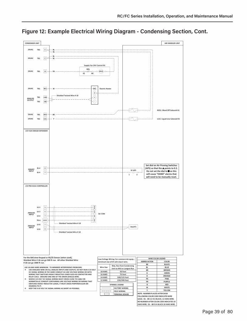
Page 39 of 80
I/O FLEX EX8160 EXPANDER
LLS1: Liquid Line Solenoid #1
BOS1: Bleed Off Solenoid #1
Supply Fan 24V Control Kit
CTB1
CTB1
BOSTB1
TB1
W1TB1
GTB1
LS1
+A6TB1
-A6TB1
SF1CBOL
X2 NC
W1
C
-
+
AIR HANDLER UNITCONDENSER UNIT
24VAC
24VAC
24VAC
24VAC
24VAC
ANALOGOUTPUT
24VAC
PK
BLBL
BLBL
W
BK
Y
Shielded Twisted Wire # 18
Electric Heater
8
7
7
BI-4
8
UI-8
SF-APS
1 3
DxLAT1
temp
comout
pwrTB-A 24VDC
SA-T/RH6
UI-3
7
5
BINARYINPUT
ANALOGINPUT
Shielded Twisted Wire # 18
Shielded Twisted Wire # 18ANALOG
INPUT
I/O PRO 812U CONTROLLER
UI-8
UI-3
UI-4
BI-4
ABBREVIATION COLORBK BLACKBL BLUEBR BROWNG GREENO ORANGEPK PINKPR PURPLER REDW WHITEY YELLOW
WIRE COLOR LEGEND
NOTE: NUMBER PLACED AFTER DASH FOLLOWING COLOR CODE INDICATES WIRE GAGE. EX. - BK-12 IS A BLACK, 12 AWG WIRE.NO NUMBER AFTER COLOR CODE INDICATES 18 AWG WIRE. EX. - BK IS A BLACK 18 AWG WIRE.
FACTORY WIRINGFIELD WIRINGTERMINAL BOARD
SYMBOL LEGEND
USE 18 AWG WIRE MINIMUM. TO MINIMIZE INTERFERENCE PROBLEMS: USE SHIELDED WIRE ON ALL ANALOG INPUTS AND OUPUTS. DO NOT RUN 0-10 VOLT
DC SIGNAL WIRING IN THE SAME CONDUIT AS LINE VOLTAGE WIRING OR WITH WIRING THAT SWITCHES HIGHLY INDUCTIVE LOADS SUCH AS CONTACTOR AND RELAY COILS. GROUND ONE END OF THE DRAIN (SHIELD) WIRE.
WHEN 0-10 VOLT DC SIGNAL WIRING MUST CROSS CLOSE TO CABLE OR NONMETALLIC CONDUIT CONTAINING LINE VOLTAGE WIRING OR WIRING THAT SWITCHES HIGHLY INDUCTIVE LOADS, IT MUST CROSS PERPENDICULAR (90 DEGREES) TO IT.
KEEP THE 0-10 VOLT DC SIGNAL WIRING AS SHORT AS POSSIBLE.
Wire SizeMax. Run from Condensing Unit to AHU or Longest Run
18 AWG 50 Feet16 AWG 75 Feet14 AWG 100/125 Feet12 AWG 150/200 Feet
Low Voltage Wiring: For commercial equip.; minimum size of 24 volt class 2 wire.
For the BACview Keypad or RS/ZS Sensor (when used), Shielded Wire # 18 can go 500 ft run. All other Shielded Wire # 18 can go 1000 ft run.
Set dial on Air Proving Switches (APS) so that the points to 0.2.
Do not set the dial to as this will cause “HAND” alarms that will need to be manually reset.
Figure 12: Example Electrical Wiring Diagram - Condensing Section, Cont.
RC/FC Series Installation, Operation, and Maintenance Manual
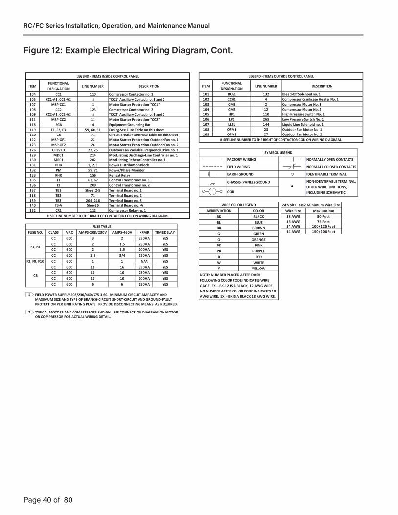
Page 40 of 80
FIELD POWER SUPPLY 208/230/460/575-3-60. MINIMUM CIRCUIT AMPACITY AND MAXIMUM SIZE AND TYPE OF BRANCH-CIRCUIT SHORT-CIRCUIT AND GROUND-FAULT PROTECTION PER UNIT RATING PLATE. PROVIDE DISCONNECTING MEANS AS REQUIRED.
TYPICAL MOTORS AND COMPRESSORS SHOWN. SEE CONNECTION DIAGRAM ON MOTOR OR COMPRESSOR FOR ACTUAL WIRING DETAIL.
FUSE NO. CLASS VAC AMPS-208/230V AMPS-460V XFMR TIME DELAYCC 600 3 2 350VA YESCC 600 2 1.5 250VA YESCC 600 2 1.5 200VA YESCC 600 1.5 3/4 150VA YES
F2, F9, F10 CC 600 1 1 N/A YESCC 600 16 16 350VA YESCC 600 10 10 250VA YESCC 600 10 10 200VA YESCC 600 6 6 150VA YES
CB
FUSE TABLE
F1, F3
2
1
ABBREVIATION COLORBK BLACKBL BLUEBR BROWNG GREENO ORANGEPK PINKPR PURPLER REDW WHITEY YELLOW
WIRE COLOR LEGEND
NOTE: NUMBER PLACED AFTER DASH FOLLOWING COLOR CODE INDICATES WIRE GAGE. EX. - BK-12 IS A BLACK, 12 AWG WIRE.NO NUMBER AFTER COLOR CODE INDICATES 18 AWG WIRE. EX. - BK IS A BLACK 18 AWG WIRE.
Wire Size Maxium Run18 AWG 50 Feet16 AWG 75 Feet14 AWG 100/125 Feet14 AWG 150/200 Feet
24 Volt Class 2 Minimum Wire Size
ITEMFUNCTIONAL DESIGNATION
LINE NUMBER DESCRIPTION
104 CC1 110 Compressor Contactor no. 1105 CC1-A1, CC1-A2 # "CC1" Auxiliary Contact no. 1 and 2107 MSP-CC1 1 Motor Starter Protection-“CC1”108 CC2 123 Compressor Contactor no. 2109 CC2-A1, CC2-A2 # "CC2" Auxiliary Contact no. 1 and 2111 MSP-CC2 11 Motor Starter Protection-“CC2”118 EGB 4 Equipment Grounding Bar119 F1, F2, F3 59, 60, 61 Fusing-See Fuse Table on this sheet120 CB 71 Circuit Breaker-See Fuse Table on this sheet122 MSP-OF1 22 Motor Starter Protection-Outdoor Fan no. 1123 MSP-OF2 26 Motor Starter Protection-Outdoor Fan no. 2126 OF1VFD 22, 25 Outdoor Fan Variable Frequency Drive no. 1129 MDC1 214 Modulating Discharge-Line Controller no. 1130 MRC1 202 Modulating Reheat Controller no. 1131 PDB 1, 2, 3 Power Distribution Block132 PM 59, 71 Power/Phase Monitor133 RHR 156 Reheat Relay135 T1 62, 67 Control Transformer no. 1136 T2 200 Control Transformer no. 2137 TB1 Sheet 2-5 Terminal Board no. 1138 TB2 71 Terminal Board no. 2139 TB3 204, 216 Terminal Board no. 3140 TB-A Sheet 5 Terminal Board no. -A152 CR1 112 Compressor Relay no. 1
LEGEND - ITEMS INSIDE CONTROL PANEL
# SEE LINE NUMBER TO THE RIGHT OF CONTACTOR COIL ON WIRING DIAGRAM.
ITEMFUNCTIONAL DESIGNATION
LINE NUMBER DESCRIPTION
101 BOS1 132 Bleed-Off Solenoid no. 1102 CCH1 4 Compressor Crankcase Heater No. 1103 CM1 2 Compressor Motor No. 1104 CM2 12 Compressor Motor No. 2105 HP1 110 High Pressure Switch No. 1106 LP1 265 Low Pressure Switch No. 1107 LLS1 144 Liquid Line Solenoid no. 1108 OFM1 23 Outdoor Fan Motor No. 1109 OFM2 27 Outdoor Fan Motor No. 2
LEGEND - ITEMS OUTSIDE CONTROL PANEL
# SEE LINE NUMBER TO THE RIGHT OF CONTACTOR COIL ON WIRING DIAGRAM.
FACTORY YLLAMRONGNIRIW OPEN CONTACTS
FIELD DESOLCYLLAMRONGNIRIW CONTACTS
EARTH ELBAIFITNEDIDNUORG TERMINAL
CHASSIS (PANEL) GROUND
COIL
SYMBOL LEGEND
NON-IDENTIFIABLE TERMINAL, OTHER WIRE JUNCTIONS, INCLUDING SCHEMATIC
Figure 12: Example Electrical Wiring Diagram, Cont.
RC/FC Series Installation, Operation, and Maintenance Manual
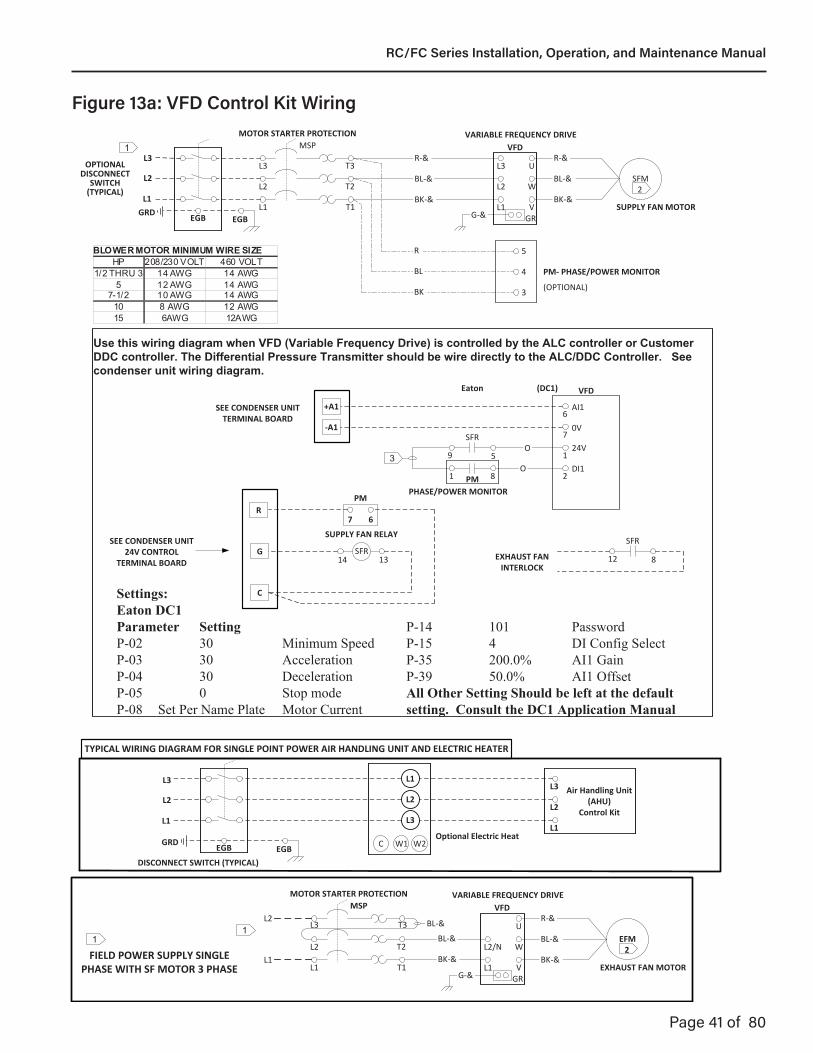
Page 41 of 80WIRING DIAGRAM# 0962I-4241A.Rev.J, VFD-CONTROL KIT, Sheet 1 of 2 08/15/18 DWN_____ CHK_____
SFR
59
Eaton VFD(DC1)
SFM2
T1
T2
T3L3
L2
L1
MSP
BK‐&
BL‐&
R‐&VFD
L2 W
L3 U
L1 VGRG‐&
BK‐&
BL‐&
R‐&
G
C
SFR14 13
SEE CONDENSER UNIT 24V CONTROL
TERMINAL BOARD
O
O
SUPPLY FAN RELAY
MOTOR STARTER PROTECTION VARIABLE FREQUENCY DRIVE
SUPPLY FAN MOTOR
SFR
812EXHAUST FAN INTERLOCK
5
4
3
81 PM
PM‐ PHASE/POWER MONITOR
(OPTIONAL)BK
BL
R
PHASE/POWER MONITOR
3
‐A1
+A1SEE CONDENSER UNIT TERMINAL BOARD
Use this wiring diagram when VFD (Variable Frequency Drive) is controlled by the ALC controller or Customer DDC controller. The Differential Pressure Transmitter should be wire directly to the ALC/DDC Controller. See condenser unit wiring diagram.
Settings:Eaton DC1Parameter SettingP-02 30 Minimum SpeedP-03 30 AccelerationP-04 30 Deceleration P-05 0 Stop modeP-08 Set Per Name Plate Motor Current
R7 6
PM
DSLWF
124V
2DI1
6
7
AI1
0V
L3
L2
L1
Air Handling Unit (AHU)
Control Kit
L1
L2
L3
EGB
L1
L2
L3
GRD
DISCONNECT SWITCH (TYPICAL)
EGB W1C W2Optional Electric Heat
TYPICAL WIRING DIAGRAM FOR SINGLE POINT POWER AIR HANDLING UNIT AND ELECTRIC HEATER
BLOWER MOTOR MINIMUM WIRE SIZE HP 208/230 VOLT 460 VOLT
1/2 THRU 3 14 AWG 14 AWG 5 12 AWG 14 AWG
7-1/2 10 AWG 14 AWG 10 8 AWG 12 AWG 15 6AWG 12AWG
1
EGB
L1
L2
L3
GRD
OPTIONAL DISCONNECT
SWITCH (TYPICAL)
EGB
EFM2
T1
T2
T3L3
L2
L1
MSP
BK‐&
BL‐&
R‐&VFD
L2/N W
U
L1 VGRG‐&
BK‐&
BL‐&
L1
L2
MOTOR STARTER PROTECTION VARIABLE FREQUENCY DRIVE
EXHAUST FAN MOTOR
1BL‐&
FIELD POWER SUPPLY SINGLE PHASE WITH SF MOTOR 3 PHASE
1
P-14 101 Password P-15 4 DI Config SelectP-35 200.0% AI1 Gain P-39 50.0% AI1 OffsetAll Other Setting Should be left at the default setting. Consult the DC1 Application Manual
Figure 13a: VFD Control Kit Wiring
RC/FC Series Installation, Operation, and Maintenance Manual

Page 42 of 80
EFR
59
Eaton VFD
124V
2DI1
6
7
AI1
0V
(DC1)
EFM2
T1
T2
T3L3
L2
L1
MSP
BK‐&
BL‐&
R‐&VFD
L2 W
L3 U
L1 VGRG‐&
BK‐&
BL‐&
R‐&
G
C
EFR14 13SEE CONDENSER UNIT
24V CONTROL TERMINAL BOARD
O
O
EXHAUST FAN RELAY
MOTOR STARTER PROTECTION VARIABLE FREQUENCY DRIVE
EXHAUST FAN MOTOR
FIELD POWER SUPPLY 208/230/460-3-60. MINIMUM CIRCUIT AMPACITY AND MAXIMUM SIZE AND TYPE OF BRANCH-CIRCUIT SHORT-CIRCUIT AND GROUND-FAULT PROTECTION PER UNIT RATING PLATE. PROVIDE DISCONNECTING MEANS AS REQUIRED.
1
TYPICAL MOTOR SHOWN. SEE WIRING CONNECTION DIAGRAM ON MOTOR FOR ACTUAL WIRING DETAIL. 2
‐A2
+A2SEE CONDENSER UNIT TERMINAL BOARD
Use this wiring diagram when VFD (Variable Frequency Drive) is controlled by the ALC controller or Customer DDC controller. The Differential Pressure Transmitter should be wire directly to the ALC/DDC Controller. See condenser unit wiring diagram.
DS LWFWIRING DIAGRAM# 0962I-4241A.Rev.J, VFD-CONTROL KIT, Sheet 2 of 2 08/15/18 DWN_____ CHK_____
BLOWER MOTOR MINIMUM WIRE SIZE HP 208/230 VOLT 460 VOLT
1/2 THRU 3 14 AWG 14 AWG 5 12 AWG 14 AWG
7-1/2 10 AWG 14 AWG 10 8 AWG 12 AWG 15 6AWG 12AWG
1
EGB
L1
L2
L3
GRD
OPTIONAL DISCONNECT
SWITCH (TYPICAL)
EGB
EFM2
T1
T2
T3L3
L2
L1
MSP
BK‐&
BL‐&
R‐&VFD
L2/N W
U
L1 VGRG‐&
BK‐&
BL‐&
L1
L2
MOTOR STARTER PROTECTION VARIABLE FREQUENCY DRIVE
EXHAUST FAN MOTOR
1BL‐&
FIELD POWER SUPPLY SINGLE PHASE WITH SF MOTOR 3 PHASE
1
Settings:Eaton DC1Parameter SettingP-03 30 AccelerationP-04 30 Deceleration P-05 0 Stop modeP-08 Set Per Name Plate Motor CurrentP-14 101 Password P-15 4 DI Config Select
All Other Setting Should be left at the default setting. Consult the DC1 Application Manual
Figure 13b: VFD Control Kit Wiring
RC/FC Series Installation, Operation, and Maintenance Manual

Page 43 of 80
PurposeThe purpose of the DPM is to monitor the line voltage sup-plying single and three phase systems, providing the oppor-tunity to disconnect equip-ment if the voltages are outside of the selectable operational parameters.
OperationIf the voltages and rotation are within the selectable set-up parameters, the DPM will ener-gize the internal relays, trans-ferring the output contacts. If the voltages and/or rotation are outside any of the set-up parameters, the DPM internal relays will not energized.
If the line voltage does not meet all of the set-up param-eters, the Default screen will toggle between the voltage screen showing the actual voltages and words describing the fault.
During transitions to relays en-ergized or relays de-energized, the remaining time in seconds is displayed above the present relay condition (“ON” or “off”).
General Operational Specifications Line Voltages Monitored: 200 to 240VAC, 1Ø, 50/60Hz 200 to 600VAC, 3Ø, 50/60HzFaults: Overvoltage Undervoltage Phase Loss Phase Rotation Phase Imbalance Frequency Out of RangeSet-Up: Membrane Buttons & Digital Display •NominalLineVoltage •Over/Undervoltagepercentage(7%to15%) •TripTimeDelay(2secondsto10seconds) •Re-StartTimeDelay(ManualResetto4minutes) •PhaseImbalancePercentage(3%to10%)Screens: Manufacture Name and Firmware Version Average Voltage, Frequency, Imbalance, Relay Status A-B, B-C & C-A Voltages, Relay Status Nominal Voltage Selection (Pay attention to 1Ø and 3Ø at the end of the voltages) Over/Undervoltage Percentage Selection Trip Time Delay Re-Start Time Delay Phase Imbalance Percentage Selection History with Last 4 Faults (Wraps back to Manufacture Name and Firmware Version)
Default Set-UpThe default set-up for the DPM as shipped from R-K Electronics is:Line Voltage: 480VAC, 3ØOver&Undervoltage: ±5%Trip Time Delay: 5 secondsRe-Start Time Delay: 5 secondsPhaseImbalance: 5%
Custom Set-UpThe DPM uses 4 membrane buttons to allow the customer to change the set-up criteria for their particular line voltage and preferred parameters. The following listings show the arrangement and selections available by moving through the menu choices. The membrane buttons allow for movement right or left with wrap around to selection criteria and up and down within a selection for specific parameters.
You can select the set-up parameters with only the supply voltage connected.
Example: From the Default screen (A-B, B-C & C-A voltages with relay status) pressing the right Arrow will take you to the line voltage selection parameters. If you want to change the nominal voltage to a different voltage, press the Up or Down arrows. Once you have the line voltage (and number of phases) that you want displayed on the screen:1. Pressing either the Right or Left arrow will set the new line voltage parameter
into memory and take you to the next screen, or2. After 30 seconds of no action, the new voltage parameter will be set into
memory and the screen will go back to the default screen.
513.204.6060 or 800.543.4936 • www.rke.com2
Figure 14a: Phase Monitor Data
RC/FC Series Installation, Operation, and Maintenance Manual

Page 44 of 80
Example: If you want to change the Re-Start Delay to 3 minutes (default is 2 minutes) and you are on the Default screen:1. Press the Right arrow until you get to the Re-Start Delay screen2. Press the Up button until you have 3 Minutes on the screen3. Pressing either the Right or Left arrow will set the new Re-Start Delay into memory
and take you to the next screen, or4. After 30 seconds of no action, the new Re-Start Delay will be set into memory and
the screen will go back to the Default screen.
ScreensManufacturer’s ScreenR-K ElectronicsDPM v0.0.00
Average Voltage ScreenVAvg Imb Hz460 0 60 off
Default – The Default screen shows the real time voltage detected on each of the 3 phases:A-B B-C C-A460 459 461 ON
Voltage Selection Screen (Vertical Format)200, 1Ø; 208, 1Ø; 220, 1Ø; 230, 1Ø; 240, 1Ø;200, 3Ø; 208, 3Ø; 220, 3Ø; 230, 3Ø; 240, 3Ø; 380, 3Ø; 415, 3Ø; 440, 3Ø; 460,3Ø;480,3Ø;575,3Ø;600,3Ø;
Over/Undervolage Percentage Screen (Vertical Format)7%,8%,9%,10%,11%,12%,13%,14%&15%
Trip Time Delay Screen (Vertical Format)2S,3S,4S,5S,6S,27S,8S,9S&10S
Re-Start Time Delay Screen (Vertical Format)Manual,2S,3S,4S,5S,6S,7S,8S,9S,10S,30S,1M,2M,3M&4M
Phase Imbalance Percentage Screen (Vertical Format)3%,4%,5%,6%,7%,8%,9%&10%
Fault Screen (Vertical Format)“0” most recent fault, “1” previous fault, “2” third oldest fault & “3” fourth oldest fault
Fault words:“Phase A Loss” (There is no voltage sensed on 3-L1/S)“Voltage Low” (Average line voltage is less than selected Undervoltage percentage)“Voltage High” (Average line voltage is more than selected Overvoltage percentage)“Imbalance” (One Phase is lower than the average voltage by more than the Imbalance percentage)“PhaseLoss” (Onephaseismorethan30%belowtheLineVoltageselection)“Bad Rotation” (The phase rotation sequence is reversed)“Bad Freq” Line frequency out of allowable range of 45 to 65Hz)
513.204.6060 or 800.543.4936 • www.rke.com 3
DPM with tabs(cover shows DPM with blocks)
L1 L2 L3460 460 460 ON
Figure 14b: Phase Monitor Data
RC/FC Series Installation, Operation, and Maintenance Manual
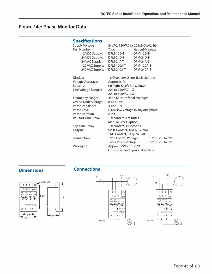
Page 45 of 80
S1
S2
•
•
Supply MS••
Auxiliary
VAvg Imb Hz� 230 0 60 ON
DPM
Supply NO C NC AUX� 6 7 8 1 2 C NO
3 4 5�L1/S L2/S L3
Motor
MSL1
L2L3
••
•
Supply MS••
Auxiliary
L1 L2 L3�460 459 460 ON
DPM
Supply NO C NC AUX� 6 7 8 1 2 C NO
3 4 5�L1/S L2/S L3
Motor
MS
3" 2"
5"4.25"
2.5"
0/25" Dia
L1 L2 L3�480 479 480 ON
DPM
Supply NO C NC AUX� 6 7 8 1 2 C NO
3 4 5�L1/S L2/S L3
SpecificationsSupply Voltage: 24VAC, 120VAC or 208/240VAC, 1ØPart Number: Tabs: Pluggable Blocks 12 VDC Supply: DPM-12D-T DPM-12D-B 24 VDC Supply: DPM-24D-T DPM-24D-B 24 VAC Supply: DPM-24A-T DPM-24A-B 120 VAC Supply: DPM-120A-T DPM-120A-B 240 VAC Supply: DPM-240A-T DPM-240A-B
Display: 16 Character, 2 line; Back LightingVoltageAccuracy: Approx±1%Buttons: (4) Right & Left, Up & DownLine Voltage Ranges: 200 to 240VAC, 1Ø 200 to 600VAC, 3ØFrequency Range: 45 to 65Hertz for all voltagesOver&Undervoltage: 8%to15%PhaseImbalance: 3%to10%PhaseLoss: ≥30%lowvoltageinanyonephasePhase Rotation: A-B-CRe-Start Time Delay: 1 second to 4 minutes Manual Reset OptionTrip Time Delay: 1 second to 30 secondsOutput: SPDT Contact, 10A @ 120VAC 1NO Contact, 6A @ 240VACTermination: Tabs:ControlVoltage: 0.187”Push-Ontabs Three Phase Voltage: 0.250” Push-On tabsPackaging: Approx. 3”W x 5”L x 2”H Dust Cover and Epoxy Filled Base
Dimensions Connections
4
Figure 14c: Phase Monitor Data
RC/FC Series Installation, Operation, and Maintenance Manual
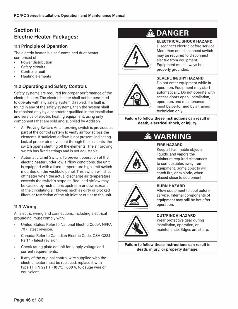
Page 46 of 80
Section 11: Electric Heater Packages:
11.1 Principle of OperationThe electric heater is a self-contained duct heater comprised of:• Power distribution• Safety circuits• Control circuit• Heating elements
11.2 Operating and Safety ControlsSafety systems are required for proper performance of the electric heater. The electric heater shall not be permitted to operate with any safety system disabled. If a fault is found in any of the safety systems, then the system shall be repaired only by a contractor qualified in the installation and service of electric heating equipment, using only components that are sold and supplied by Addison.
• Air Proving Switch: An air proving switch is provided as part of the control system to verify airflow across the elements. If sufficient airflow is not present, indicating lack of proper air movement through the elements, the switch opens shutting off the elements. The air proving switch has fixed settings and is not adjustable.
• Automatic Limit Switch: To prevent operation of the electric heater under low airflow conditions, the unit is equipped with a fixed temperature high limit switch mounted on the vestibule panel. This switch will shut off heater when the actual discharge air temperature exceeds the switch's setpoint. Reduced airflow may be caused by restrictions upstream or downstream of the circulating air blower, such as dirty or blocked filters or restriction of the air inlet or outlet to the unit.
11.3 WiringAll electric wiring and connections, including electrical grounding, must comply with;
• United States: Refer to National Electric Code®, NFPA 70 - latest revision.
• Canada: Refer to Canadian Electric Code, CSA C22.1 Part 1 - latest revision.
• Check rating plate on unit for supply voltage and current requirements.
• If any of the original control wire supplied with the electric heater must be replaced, replace it with type THHN 221° F (105°C), 600 V, 16 gauge wire or equivalent.
DANGERELECTRICAL SHOCK HAZARDDisconnect electric before service. More than one disconnect switch may be required to disconnect electric from equipment. Equipment must always be properly grounded.
WARNINGFIRE HAZARD Keep all flammable objects, liquids, and vapors the minimum required clearances to combustibles away from equipment. Some objects will catch fire, or explode, when placed close to equipment.
SEVERE INJURY HAZARDDo not enter equipment while in operation. Equipment may start automatically. Do not operate with access doors open. Installation, operation, and maintenance must be performed by a trained technician only.
BURN HAZARD Allow equipment to cool before service. Internal components of equipment may still be hot after operation.
CUT/PINCH HAZARD Wear protective gear during installation, operation, or maintenance. Edges are sharp.
Failure to follow these instructions can result in death, electrical shock, or injury.
Failure to follow these instructions can result in death, injury, or property damage.
RC/FC Series Installation, Operation, and Maintenance Manual
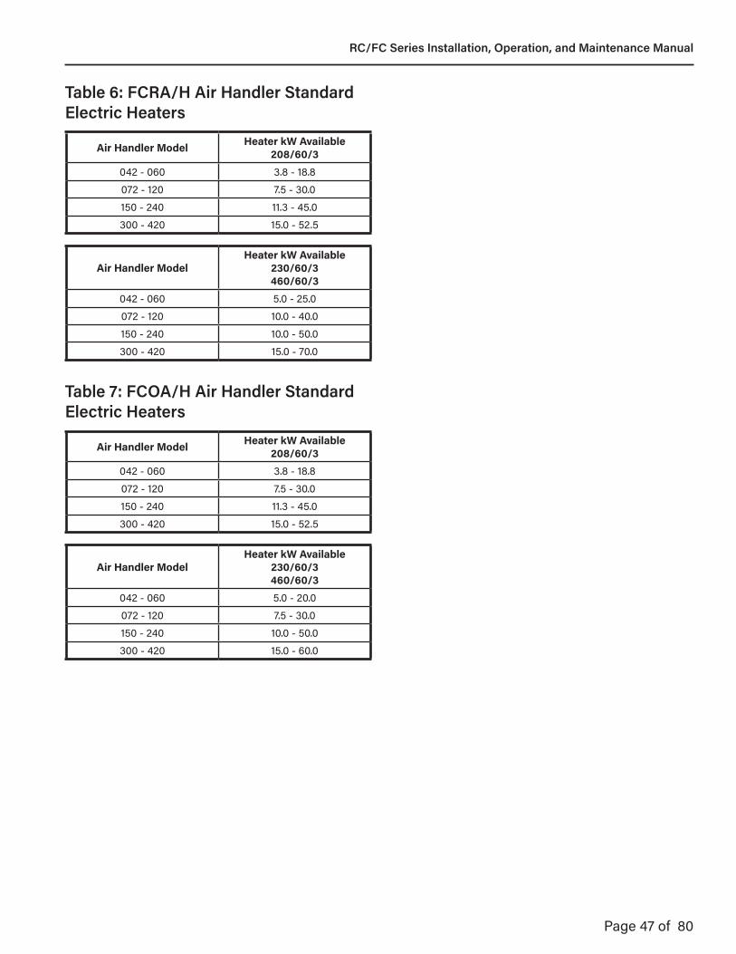
Page 47 of 80
Air Handler Model Heater kW Available208/60/3
042 - 060 3.8 - 18.8072 - 120 7.5 - 30.0150 - 240 11.3 - 45.0300 - 420 15.0 - 52.5
Air Handler ModelHeater kW Available
230/60/3460/60/3
042 - 060 5.0 - 25.0072 - 120 10.0 - 40.0150 - 240 10.0 - 50.0300 - 420 15.0 - 70.0
Air Handler Model Heater kW Available208/60/3
042 - 060 3.8 - 18.8072 - 120 7.5 - 30.0150 - 240 11.3 - 45.0300 - 420 15.0 - 52.5
Air Handler ModelHeater kW Available
230/60/3460/60/3
042 - 060 5.0 - 20.0072 - 120 7.5 - 30.0150 - 240 10.0 - 50.0300 - 420 15.0 - 60.0
Table 6: FCRA/H Air Handler Standard Electric Heaters
Table 7: FCOA/H Air Handler Standard Electric Heaters
RC/FC Series Installation, Operation, and Maintenance Manual

Page 48 of 80
Figure 15: Typical Air Handler Wiring Diagram
SFC
L3
L2
L1 T1
T2
T3SFM
5
4
3
SFCA1A281
PM
PM
1
R‐14
BL‐14
BK‐14
BK
BL
R
G‐14
(OPTIONAL)(OPTIONAL)
2 BOL
L3 T3
L2 T2
L1 T1
SF-OLR‐14
BK‐14
PK67
BL
L1
G
C
L2
L3
TB1
FROM CONDENDING UNIT24VAC TERMINAL BOARD
FIELD POWER SUPPLYSEE AIR HANDLER UNIT
RATING PLATE
3 PHASE UNITS GRDEGL
SFC‐A
OPTIONAL FAN INTERLOCK RELAY
R
SFC
L2
L3 T3
T2SFM
4
3PM
1BK‐14
R‐14
BK
R
G‐14
(OPTIONAL)
L3 T3
L2 T2
L1 T1
SF-OLR‐14
BK‐14L2 T2
R‐14R‐14
SFCA1A2
G
C
TB1
L1
L2
FROM CONDENSING UNIT24VAC TERMINAL BOARD
FIELD POWER SUPPLYSEE AIR HANDLER UNIT
RATING PLATE
BL
1 PHASE UNITSGRD
EGL
SFC‐A
OPTIONAL FAN INTERLOCK RELAY
2 BOLPK
R
81
PM (OPTIONAL)
67BL
1 TYPICAL MOTOR SHOWN; SEE CONNECTION DIAGRAM ON MOTOR FOR ACTUAL WIRING DETAIL.
SHEET 1 OF 1
HCA/VCA/HCC/VCC CONTROL KIT w/POWER MONITOR208/230/460‐3‐60 AND 208/230/460‐1‐60
DWN______ CKD______
03/31/16
WIRING DIAGRAM
0962I‐3365,Rev.E
DS LWF
2 THIS WIRE CONNECTS DIRECTLY TO TERMINAL G OF “TB1” WHEN OPTIONAL POWER MONITOR IS NOT USED.
FUNCTIONAL DESIGNATION
SFC SUPPLY FAN CONTACTOR
SFM SUPPLY FAN MOTOR
DESCRIPTION
EGL EQUIPMENT GROUNDING LUG
LEGEND
PM POWER MONITOR
TB TERMINAL BOARD
SFC‐A “SFC”‐ AUXILIARY CONTACT
SF‐OL SUPPLY FAN OVERLOAD RELAY
L3
L2
L1
Air Handling Unit (AHU)
Control Kit
L1
L2
L3
EGB
L1
L2
L3
GRD
DISCONNECT SWITCH (TYPICAL)
EGB W1C W2
Optional Electric Heat
TYPICAL WIRING DIAGRAM FOR SINGLE POINT POWER AIR HANDLING UNIT AND ELECTRIC HEATER
EARTH GROUNDCHASSIS (PANEL) GROUND
SYMBOL LEGEND
FIELD WIRING
NORMALLY OPEN CONTACT
FACTORY WIRING
FACTORY WIRING
NORMALLY CLOSE CONTACT
SFC
L3
L2
L1 T1
T2
T3SFM
5
4
3
SFCA1A281
PM
PM
1
R‐14
BL‐14
BK‐14
BK
BL
R
G‐14
(OPTIONAL)(OPTIONAL)
2 BOL
L3 T3
L2 T2
L1 T1
SF-OLR‐14
BK‐14
PK67
BL
L1
G
C
L2
L3
TB1
FROM CONDENDING UNIT24VAC TERMINAL BOARD
FIELD POWER SUPPLYSEE AIR HANDLER UNIT
RATING PLATE
3 PHASE UNITS GRDEGL
SFC‐A
OPTIONAL FAN INTERLOCK RELAY
R
SFC
L2
L3 T3
T2SFM
4
3PM
1BK‐14
R‐14
BK
R
G‐14
(OPTIONAL)
L3 T3
L2 T2
L1 T1
SF-OLR‐14
BK‐14L2 T2
R‐14R‐14
SFCA1A2
G
C
TB1
L1
L2
FROM CONDENSING UNIT24VAC TERMINAL BOARD
FIELD POWER SUPPLYSEE AIR HANDLER UNIT
RATING PLATE
BL
1 PHASE UNITSGRD
EGL
SFC‐A
OPTIONAL FAN INTERLOCK RELAY
2 BOLPK
R
81
PM (OPTIONAL)
67BL
1 TYPICAL MOTOR SHOWN; SEE CONNECTION DIAGRAM ON MOTOR FOR ACTUAL WIRING DETAIL.
SHEET 1 OF 1
HCA/VCA/HCC/VCC CONTROL KIT w/POWER MONITOR208/230/460‐3‐60 AND 208/230/460‐1‐60
DWN______ CKD______
03/31/16
WIRING DIAGRAM
0962I‐3365,Rev.E
DS LWF
2 THIS WIRE CONNECTS DIRECTLY TO TERMINAL G OF “TB1” WHEN OPTIONAL POWER MONITOR IS NOT USED.
FUNCTIONAL DESIGNATION
SFC SUPPLY FAN CONTACTOR
SFM SUPPLY FAN MOTOR
DESCRIPTION
EGL EQUIPMENT GROUNDING LUG
LEGEND
PM POWER MONITOR
TB TERMINAL BOARD
SFC‐A “SFC”‐ AUXILIARY CONTACT
SF‐OL SUPPLY FAN OVERLOAD RELAY
L3
L2
L1
Air Handling Unit (AHU)
Control Kit
L1
L2
L3
EGB
L1
L2
L3
GRD
DISCONNECT SWITCH (TYPICAL)
EGB W1C W2
Optional Electric Heat
TYPICAL WIRING DIAGRAM FOR SINGLE POINT POWER AIR HANDLING UNIT AND ELECTRIC HEATER
EARTH GROUNDCHASSIS (PANEL) GROUND
SYMBOL LEGEND
FIELD WIRING
NORMALLY OPEN CONTACT
FACTORY WIRING
FACTORY WIRING
NORMALLY CLOSE CONTACT
RC/FC Series Installation, Operation, and Maintenance Manual
Page 49 of 80
Section 12: Sequence of Operation: DANGER
ELECTRICAL SHOCK HAZARDDisconnect electric before service. More than one disconnect switch may be required to disconnect electric from equipment. Equipment must always be properly grounded.
12.1 Unit ConfigurationBased on the unit's application, the unit may be configured in any number styles to achieve the described functionality. Refer to the unit’s model number to see which configuration the unit was supplied with.
12.2 Controls OptionsUnit may be controlled in one of the following ways:
• Factory-mounted ALC controls (by factory)
• Factory-mounted DDC controls (by others)
• Factory-mounted terminal strip for field-mounted
• Factory-mounted terminal strip for electromechanical controls (by factory or by others)
Unit Nomenclature Control Options:A = ALC, Standard Program, DOASB = ALC, Standard Program, RecirculatingC = ALC, Standard Program, DOAS with LOND = ALC, Standard Program, Recirculating with LONE = Controls by Others, Factory MountedF = Terminal Strip, Controls Provided and Mounted by OthersG = Remote ThermostatH = Compressor Lockout Thermostat
12.2.1 Factory-Mounted ALC Controls (by factory)The ALC control option consists of a factory programmed controller and a series of factory-wired sensors. The controller can operate in a 100% stand alone mode with the use of a hand-held display. It can also connect to a building automation system (BMS) using one of four compatible protocols (BACnet®, LonWorks with the optional Echelon card, Modbus, N2). The point mapping to these protocols can be pre-set, so that the protocol and baud rates desired can be easily field-selected without the need for additional downloads or technician assistance.Depending on the options ordered, remote sensors may be installed and wired to the controller.
12.2.2 Factory-Mounted DDC Controls (by others)Field-supplied DDC controls are mounted by the factory per the customer’s specifications.
12.2.3 Factory-Mounted Terminal Strip for Field-Mounted DDC Controls (by others)Field-supplied DDC controls can be connected to the factory-mounted and factory-wired terminal strip.
12.2.4 Factory-Mounted Terminal Strip for Remote Thermostat (by factory or by others)A factory-supplied or field-supplied thermostat can be connected to the factory-mounted and factory wired terminal. The 24V factory-supplied thermostat has the following capabilities:
• Up to 4 heat/2 cool with humidity control - for heat pump
• Up to 3 heat/2 cool with humidity control - for straight cool
The thermostat features a 45-90 °F [7-32 °C] temperature control range with a +/- 1 °F [0.5 °C] accuracy and are capable of connecting to optional factory-supplied remote indoor air and outdoor air temperature sensors.
Figure 16: Equipment Touch Display
RC/FC Series Installation, Operation, and Maintenance Manual
Page 50 of 80
12.3 Basic Sequence of OperationAll sequence of operation information for units controlled with ALC controls is available in the ALC Sequence of Operation documents that can be requested from your manufacturer’s Addison representative for each specific job.
• Sequence of operation information specifically for the operation of the electric heater modules within the above referenced document.
For sequence of operation information for units controlled with field-supplied DDC controls (whether factory-mounted or field-mounted), consult the DDC controls manufacturer and/or installer.
12.4 Accessory Controls OptionsAccessory controls options include, but are not limited to:
• Carbon Dioxide Detector: This option provides a room-mounted carbon dioxide detector for initiating additional outdoor ventilation.
• Clogged Filter Indicator: This section provides a differential pressure switch and status indication.
• Exhaust Fan Interlock: This option provides an interlock between an exhaust fan and the unit.
• Firestat: This option de-energizes the unit when the stat, mounted in the return air section, senses return air above 135 °F (57.2 °C). The firestat must be manually reset.
• Freezestat: This option shuts down the unit when the discharge temperature falls below the controller’s setpoint.
• Service Receptacle: This option provides a 115V service receptacle with 15A breaker. It is mounted in a 2” x 4” (51cm x 10.2cm) enclosure. It can be field-wired or factory-wired (outdoor condensing section only).
• Smoke Detector: This option provides an ionization type supply air smoke detector which shuts off the unit if smoke is detected.
RC/FC Series Installation, Operation, and Maintenance Manual
Page 51 of 80
Section 13: Start-Up Procedure: DANGER
ELECTRICAL SHOCK HAZARDDisconnect electric before service. More than one disconnect switch may be required to disconnect electric from equipment. Equipment must always be properly grounded.
SEVERE INJURY HAZARDDo not enter equipment while in operation. Equipment may start automatically. Do not operate with access doors open. Installation, operation, and maintenance must be performed by a trained technician only.
Failure to follow these instructions can result in death, electrical shock, or injury.
BURN HAZARD Allow equipment to cool before service. Internal components of equipment may still be hot after operation.
WARNING
FALLING HAZARDUse proper safety equipment and practices to avoid falling. Do not use any part of the equipment as a support.
Failure to follow these instructions can result in death, injury, or property damage.
Installation Code and Quarterly Inspections:All installation and service of ADDISON® equipment must be performed by a contractor qualified in the installation and service of equipment sold and supplied by Addison and conform to all requirements set forth in the ADDISON® manuals and all applicable governmental authorities pertaining to the installation, service operation and labeling of the equipment.
To help facilitate optimum performance and safety, Addison recommends that a qualified contractor conduct, at a minimum, quarterly inspections of your ADDISON® equipment and perform service where necessary, using only replacement parts sold and supplied by Addison.
Check installation site to ensure all codes and engineering specifications are correct. This section of the manual is intended to be used as an instructional guide to the commissioning of the unit. Fill out the attached start up sheet (located at the back of the manual) as each step of the procedure is performed. This procedure should be completed by the commissioning contractor and returned to Addison.
13.1 Tools & Supplies Required1. 5/16” Allen Key to Unlock Unit Doors2. Equipment Touch3. Refrigeration Manifold Gages4. Refrigeration Wrench5. Multimeter6. Temperature Sensors7. Clamp-On Temperature Probe8. Socket Wrenches 9. Small Flat Heat Screwdriver10. Refrigerant Oil11. R-410A Refrigerant
Figure 17: P-Trap Configuration
RC/FC Series Installation, Operation, and Maintenance Manual
Page 52 of 80
13.2 Pre-Start Checks13.2.1 Ductwork and Electrical ConnectionsEnsure that the following ductwork and electrical connections have been made:
• Ductwork: Supply and return air connections.
• Electrical: Line voltage power, control voltage power and remote sensor connections.
13.2.2 Condensate DrainUnits are provided with condensate drain connection(s). Do not operate unit unless a P-Trap is constructed and attached to drain connection. See Figure 15. Unit must be level or slightly inclined towards drain. Drain should pitch down and away from the unit. P-Trap pipe diameter should be the same as the drain connection diameter. Units with high internal and external static pressure drops will require a deeper trap. Prime the trap before operating the unit.
13.2.3 Supply Fans1. Make sure electrical power is isolated.2. Check power settings for voltage and verify that they
correspond with the data on the motor plate.3. Check that the motor is grounded (earthed).4. Check that all electrical leads are sufficiently insulated.5. Check that all electrical and system connections are
properly made and tightened.6. Check that all nuts, bolts and setscrews are tightened.7. Check that the blower wheel and drive assembly
turns freely without rubbing.8. Check that belt drives are tightened, properly aligned
and tensioned.9. Bump the motor.10. Check rotation.
13.2.4 CompressorsWith the supply fan operational, prepare for compressor operation.
1. Verify that the crankcase heaters are operating. These should operate for at least 24 hours before starting the compressors. Crankcase heaters must be operating during off cycles to prevent liquid refrigerant from migrating to the compressor crankcase.
13.2.5 Hot Water Heating Coils (Optional)1. Check all plumbing to the hot water heating coil is
complete and free of leaks. 2. Check that all air has been eliminated from the water
loop and coil. 3. Check that flow rates match the nominal GPM listed in
the table below.
RC/FC Series Installation, Operation, and Maintenance Manual
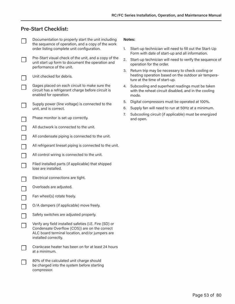
Page 53 of 80
Documentation to properly start the unit including the sequence of operation, and a copy of the work order listing complete unit configuration.
Pre-Start visual check of the unit, and a copy of the unit start up form to document the operation and performance of the unit.
Unit checked for debris.
Gages placed on each circuit to make sure the circuit has a refrigerant charge before circuit is enabled for operation.
Supply power (line voltage) is connected to the unit, and is correct.
Phase monitor is set up correctly.
All ductwork is connected to the unit.
All condensate piping is connected to the unit.
All refrigerant lineset piping is connected to the unit.
All control wiring is connected to the unit.
Filed installed parts (if applicable) that shipped lose are installed.
Electrical connections are tight.
Overloads are adjusted.
Fan wheel(s) rotate freely.
O/A dampers (if applicable) move freely.
Safety switches are adjusted properly.
Verify any field installed safeties (I.E. Fire (SD) or Condensate Overflow (COS)) are on the correct ALC board terminal location, and/or jumpers are installed correctly.
Crankcase heater has been on for at least 24 hours at a minimum.
80% of the calculated unit charge should be charged into the system before starting compressor.
Pre-Start Checklist:
Notes:
1. Start-up technician will need to fill out the Start-Up Form with date of start-up and all information.
2. Start-up technician will need to verify the sequence of operation for the order.
3. Return trip may be necessary to check cooling or heating operation based on the outdoor air tempera-ture at the time of start-up.
4. Subcooling and superheat readings must be taken with the reheat circuit disabled, and in the cooling mode.
5. Digital compressors must be operated at 100%.
6. Supply fan will need to run at 50Hz at a minimum.
7. Subcooling circuit (if applicable) must be energized and open.
☐
☐
☐☐
☐
☐☐☐☐☐☐
☐☐☐☐☐☐
☐
☐
RC/FC Series Installation, Operation, and Maintenance Manual

Page 54 of 80
Table 9: Superheat and Subcooling - 100% OAAmbient Air Temperature 95°F 85°F 75°F 65°F 55°F 45°F
Subcooling10° - 12°F 8° - 10°F
In Heating ModeNo Reheat
Subcooling10 - 12°F 8°F - 12°F
In Heating ModeWith Reheat
Superheat 8°F - 15°F 6°F - 15°F In Heating Mode
Note: Subcooling and superheat readings must be taken with the reheat circuit disabled and in the cooling mode.
Table 10: Superheat and Subcooling - RecirculatingAmbient Air Temperature 95°F 85°F 75°F 65°F 55°F 45°F
Subcooling 10° - 12°F 8° - 10°F 6°F - 10°FSuperheat 8°F - 15°F 6°F - 15°F 6°F - 10°F
Note: Subcooling and superheat readings must be taken with the reheat circuit disabled and in the cooling mode.
Table 11: Superheat and Subcooling - Heat PumpAmbient Air Temperature 95°F 85°F 75°F 65°F 55°F 45°F
Subcooling 8° - 12°F 8° - 10°F In Heating ModeSuperheat 6°F - 15°F In Heating Mode
Note: Subcooling and superheat readings must be taken with the reheat circuit disabled and in the cooling mode.
Table 8: Hot Water Heating Coil Flow Rate and Pressure Drop
Air Handler Model Cabinet Nominal GPM(Water Only)
Pressure Drop(FT, H2O)
042 - 072 A 5.0 1.72096 - 120 B 10.0 5.96150 - 210 C 16.0 2.10240 - 360 D 25.0 3.20
420 E 40.0 5.80
RC/FC Series Installation, Operation, and Maintenance Manual
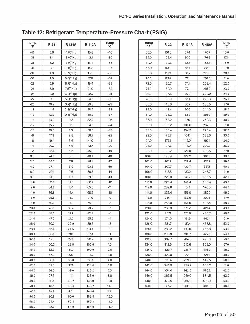
Page 55 of 80
Temp °F R-22 R-134A R-410A Temp
°CTemp
°F R-22 R-134A R-410A Temp °C
-40 0.6 14.8(“Hg) 10.8 -40 60.0 101.6 57.4 170.7 16.0-38 1.4 13.9(“Hg) 12.1 -39 62.0 105.4 60.0 176.6 17.0-36 2.2 12.9(“Hg) 13.4 -38 64.0 109.3 62.7 182.7 18.0-34 3.1 12.0(“Hg) 14.8 -37 66.0 113.2 65.4 188.9 19.0-32 4.0 10.9(“Hg) 16.3 -36 68.0 117.3 68.2 195.3 20.0-30 4.9 9.8(“Hg) 17.8 -34 70.0 121.4 71.1 201.8 21.0-28 5.9 8.7(“Hg) 19.4 -33 72.0 125.7 74.1 208.4 22.0-26 6.9 7.5(“Hg) 21.0 -32 74.0 130.0 77.1 215.2 23.0-24 8.0 6.3(“Hg) 22.7 -31 76.0 134.5 80.2 222.2 24.0-22 9.1 5.0(“Hg) 24.5 -30 78.0 139.0 83.4 229.3 26.0-20 10.2 3.7(“Hg) 26.3 -29 80.0 143.6 86.7 236.5 27.0-18 11.4 2.3(“Hg) 28.2 -28 82.0 148.4 90.0 244.0 28.0-16 12.6 0.8(“Hg) 30.2 -27 84.0 153.2 93.5 251.6 29.0-14 13.9 0.3 32.2 -26 86.0 158.2 97.0 259.3 30.0-12 15.2 1.1 34.3 -24 88.0 163.2 100.6 267.3 31.0-10 16.5 1.9 36.5 -23 90.0 168.4 104.3 275.4 32.0-8 17.9 2.8 38.7 -22 92.0 173.7 108.1 283.6 33.0-6 19.4 3.6 41.0 -21 94.0 179.1 112.0 292.1 34.0-4 20.9 4.6 43.4 -20 96.0 184.6 115.9 300.7 36.0-2 22.4 5.5 45.9 -19 98.0 190.2 120.0 309.5 37.00.0 24.0 6.5 48.4 -18 100.0 195.9 124.2 318.5 38.02.0 25.7 7.5 51.1 -17 102.0 201.8 128.4 327.7 39.04.0 27.4 8.5 53.8 -16 104.0 207.7 132.7 337.1 40.06.0 29.1 9.6 56.6 -14 106.0 213.8 137.2 346.7 41.08.0 31.0 10.8 59.5 -13 108.0 220.0 141.7 356.5 42.010.0 32.8 11.9 62.4 -12 110.0 226.4 146.4 366.4 43.012.0 34.8 13.1 65.5 -11 112.0 232.8 151.1 376.6 44.014.0 36.8 14.4 68.6 -10 114.0 239.4 156.0 387.0 46.016.0 38.8 15.7 71.9 -9 116.0 246.1 160.9 397.6 47.018.0 40.9 17.0 75.2 -8 118.0 253.0 166.0 408.4 48.020.0 43.1 18.4 78.7 -7 120.0 260.0 171.2 419.4 49.022.0 45.3 19.9 82.2 -6 122.0 267.1 176.5 430.7 50.024.0 47.6 21.3 85.8 -4 124.0 274.3 181.8 442.1 51.026.0 50.0 22.9 89.6 -3 126.0 281.7 187.4 453.8 52.028.0 52.4 24.5 93.4 -2 128.0 289.2 193.0 465.8 53.030.0 55.0 26.1 97.4 -1 130.0 296.9 198.7 477.9 54.032.0 57.5 27.8 101.4 0.0 132.0 304.7 204.6 490.3 56.034.0 60.2 29.5 105.6 1.0 134.0 312.6 210.6 503.0 57.036.0 62.9 31.3 109.9 2.0 136.0 320.7 216.7 515.9 58.038.0 65.7 33.1 114.3 3.0 138.0 329.0 222.9 529.1 59.040.0 68.6 35.0 118.8 4.0 140.0 337.4 229.2 542.5 60.042.0 71.5 37.0 123.4 6.0 142.0 345.9 235.7 556.2 61.044.0 74.5 39.0 128.2 7.0 144.0 354.6 242.3 570.2 62.046.0 77.6 41.1 133.0 8.0 146.0 363.5 249.0 584.5 63.048.0 80.8 43.2 138.0 9.0 148.0 372.5 255.9 599.0 64.050.0 84.1 45.4 143.2 10.0 150.0 381.7 262.9 613.9 66.052.0 87.4 47.7 148.4 11.054.0 90.8 50.0 153.8 12.056.0 94.4 52.4 159.3 13.058.0 98.0 54.9 164.9 14.0
Table 12: Refrigerant Temperature-Pressure Chart (PSIG)
RC/FC Series Installation, Operation, and Maintenance Manual

Page 56 of 80
DANGERELECTRICAL SHOCK HAZARDDisconnect electric before service. More than one disconnect switch may be required to disconnect electric from equipment. Equipment must always be properly grounded.
SEVERE INJURY HAZARDDo not enter equipment while in operation. Equipment may start automatically. Do not operate with access doors open. Installation, operation, and maintenance must be performed by a trained technician only.
Failure to follow these instructions can result in death, electrical shock, or injury.
Section 14 Start-Up Form:
BURN HAZARD Allow equipment to cool before service. Internal components of equipment may still be hot after operation.
WARNING
FALLING HAZARDUse proper safety equipment and practices to avoid falling. Do not use any part of the equipment as a support.
Failure to follow these instructions can result in death, injury, or property damage.
EXPLOSION HAZARDSystem contains R-410A refrigerant. Operating pressures may exceed limits of R-22 service equipment. Use proper refrigerant handling practices, tools, and equipment. Failure to follow these instructions can result in death, injury, or property damage.
Field start-up should be performed by a qualified technician.
The technician is responsible for assuring that all of the items on the unit start-up checklist are properly installed and operating. Upon completion, a copy of the form should be returned to Addison, using the contact information listed.
Installation Code and Quarterly Inspections: All installation and service of ADDISON® equipment must be performed by a contractor qualified in the installation and service of equipment sold and supplied by Addison and conform to all requirements set forth in the ADDISON® manuals and all applicable governmental authorities pertaining to the installation, service, operation and labeling of the equipment.
To help facilitate optimum performance and safety, Addison recommends that a qualified contractor conduct, at a minimum, quarterly inspections of your ADDISON® equipment and perform service where necessary, using only replacement parts sold and supplied by Addison.
Further Information: Applications engineering and detailed guidance on systems design, installation and equipment performance is available through ADDISON® representatives. Please contact us for any further information you may require, including the Installation, Operation and Service Manual.
This product is not for residential use. This document is intended to assist licensed professionals in the exercise of their professional judgment.
RC/FC Series Installation, Operation, and Maintenance Manual

Split System Unit
START-UP FORM:RC/FC Series
DANGERELECTRICAL SHOCK HAZARDDisconnect electric before service. More than one disconnect switch may be required to disconnect electric from equipment. Equipment must always be properly grounded.
SEVERE INJURY HAZARDDo not enter equipment while in operation. Equipment may start automatically. Do not operate with access doors open. Installation, operation, and maintenance must be performed by a trained technician only.
BURN HAZARD Allow equipment to cool before service. Internal components of equipment may still be hot after operation.
WARNING
FALLING HAZARDUse proper safety equipment and practices to avoid falling. Do not use any part of the equipment as a support.
Failure to follow these instructions can result in death, injury, or property damage.
EXPLOSION HAZARDSystem contains R-410A refrigerant. Operating pressures may exceed limits of R-22 service equipment. Use proper refrigerant handling practices, tools, and equipment. Failure to follow these instructions can result in death, injury, or property damage.
7050 Overland RoadOrlando, FL 32810
Tel.: 407-292-4400 ∙ Fax: 407-290-1329www.addison-hvac.com
DEDICATED OUTDOOR AIR SPECIALISTS
Part Number:ADFMRCST
Rev.: 06 June 2018DS
*ADFMRCST*Field start-up should be performed by a qualified technician.
The technician is responsible for assuring that all of the items on the unit start-up checklist are properly installed and operating. Upon completion, a copy of the form should be returned to Addison, using the contact information listed.
Installation Code and Quarterly Inspections: All installation and service of ADDISON® equipment must be performed by a contractor qualified in the installation and service of equipment sold and supplied by Addison and conform to all requirements set forth in the ADDISON® manuals and all applicable governmental authorities pertaining to the installation, service, operation and labeling of the equipment.
To help facilitate optimum performance and safety, Addison recommends that a qualified contractor conduct, at a minimum, quarterly inspections of your ADDISON® equipment and perform service where necessary, using only replacement parts sold and supplied by Addison.
Further Information: Applications, engineering and detailed guidance on systems design, installation and equipment performance is available through ADDISON® representatives. Please contact us for any further information you may require, including the Installation, Operation and Service Manual.
This product is not for residential use. This document is intended to assist licensed professionals in the exercise of their professional judgment.
Technician Name:
Start-Up Date:
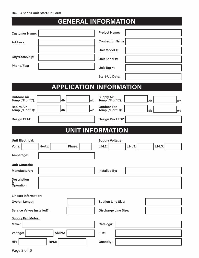
Page 2 of 6
RC/FC Series Unit Start-Up Form
GENERAL INFORMATION
Customer Name:
Address:
City/State/Zip:
Phone/Fax:
Project Name:
Contractor Name:
Unit Model #:
Unit Serial #:
Unit Tag #:
Start-Up Date:
APPLICATION INFORMATIONOutdoor Air Temp (°F or °C):
Return Air Temp (°F or °C):
Design CFM:
Supply Air Temp (°F or °C):
Outdoor Fan Temp (°F or °C):
Design Duct ESP:
db
db
wb
wb
db
db
wb
wb
UNIT INFORMATION
Supply Fan Motor:
Make:
Voltage:
HP:
Catalog#:
FR#:
Quantity:
Unit Electrical:
Volts:
Amperage:
Supply Voltage:
L1-L2:
Unit Controls:
Manufacturer:
Description& Operation:
Installed By:
Hertz: Phase: L2-L3: L1-L3:
AMPS:
RPM:
Lineset Information:
Overall Length:
Service Valves Installed?:
Suction Line Size:
Discharge Line Size:
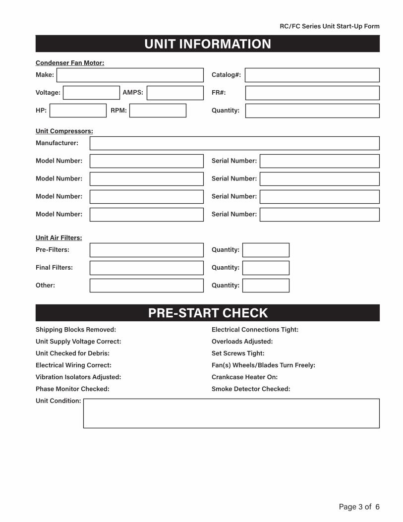
Page 3 of 6
RC/FC Series Unit Start-Up Form
UNIT INFORMATION
Unit Compressors:
Manufacturer:
Model Number:
Model Number:
Model Number:
Model Number:
Serial Number:
Serial Number:
Serial Number:
Serial Number:
PRE-START CHECKShipping Blocks Removed:
Unit Supply Voltage Correct:
Unit Checked for Debris:
Electrical Wiring Correct:
Vibration Isolators Adjusted:
Phase Monitor Checked:
Unit Condition:
Electrical Connections Tight:
Overloads Adjusted:
Set Screws Tight:
Fan(s) Wheels/Blades Turn Freely:
Crankcase Heater On:
Smoke Detector Checked:
Condenser Fan Motor:
Make:
Voltage:
HP:
Catalog#:
FR#:
Quantity:
AMPS:
RPM:
Unit Air Filters:
Pre-Filters:
Final Filters:
Other:
Quantity:
Quantity:
Quantity:

Page 4 of 6
RC/FC Series Unit Start-Up Form
START-UP CHECKSupply Motor AMPS:
OA Damper Operation:
Return Damper Operation:
L1 L2 L3 RPM
Hot Water:
Actuator:
HEATING CHECKHeating Type:
Control Valve:
Heat Stages:
Unit Safeties Operate Properly:
Electric Heat AMPS:
Comments:
Electric: kW:
L1 L2 L3
COOLING CHECKRefrigerant Type:
Unit Safeties Operate Properly:
Comments:
Number of Circuits:
Fans Run & Cycle Properly:
Charge:
Actuator:

Page 5 of 6
RC/FC Series Unit Start-Up Form
COOLING CHECKCompressor Circuit #1:
Suction Pressure:
Discharge Pressure:
Liquid Pressure:
Superheat:
Subcooling:
Compressor 1 AMPS:
Compressor 2 AMPS:
Suction Temp:
Discharge Temp:
Liquid Temp:
To Calculate Superheat: Convert suction pressure to saturation temperature, then subtract the suction line temperature.
L1
L1
L2
L2
L3
L3
RLA
RLA
Saturation Temp:
Saturation Temp:
To Calculate Subcooling: Convert liquid line pressure to condensing tempera-ture, then subtract the liquid line temperature.
Compressor Circuit #2:
Suction Pressure:
Discharge Pressure:
Liquid Pressure:
Superheat:
Subcooling:
Compressor 1 AMPS:
Compressor 2 AMPS:
Suction Temp:
Discharge Temp:
Liquid Temp:
To Calculate Superheat: Convert suction pressure to saturation temperature, then subtract the suction line temperature.
L1
L1
L2
L2
L3
L3
RLA
RLA
Saturation Temp:
Saturation Temp:
To Calculate Subcooling: Convert liquid line pressure to condensing tempera-ture, then subtract the liquid line temperature.
Condenser Fans:
Condenser Fan 1 AMPS:
Condenser Fan 2 AMPS:
Condenser Fan 3 AMPS:
Condenser Fan 4 AMPS:
Condenser Fan 5 AMPS:
Condenser Fan 6 AMPS:
L1
L1
L2
L2
L3
L3
L1
L1
L2
L2
L3
L3
L1
L1
L2
L2
L3
L3
Hot Gas Bypass/Hot Gas Reheat:
Hot Gas Bypass # of Stages:
Hot Gas Reheat # of Stages:
Setpoint:
Setpoint:
1:
1:
2:
2:
3: 4:
Unloading Switch:
Cut In:
Cut Out:

Page 6 of 6
RC/FC Series Unit Start-Up Form
Comments:
Owner’s Representative:
Signature:
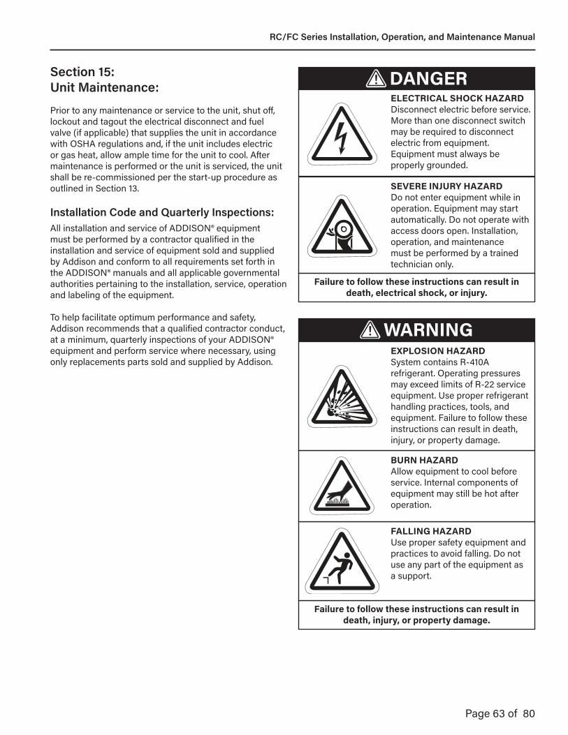
Page 63 of 80
Section 15: Unit Maintenance: DANGER
ELECTRICAL SHOCK HAZARDDisconnect electric before service. More than one disconnect switch may be required to disconnect electric from equipment. Equipment must always be properly grounded.
SEVERE INJURY HAZARDDo not enter equipment while in operation. Equipment may start automatically. Do not operate with access doors open. Installation, operation, and maintenance must be performed by a trained technician only.
Failure to follow these instructions can result in death, electrical shock, or injury.
BURN HAZARD Allow equipment to cool before service. Internal components of equipment may still be hot after operation.
WARNING
FALLING HAZARDUse proper safety equipment and practices to avoid falling. Do not use any part of the equipment as a support.
Failure to follow these instructions can result in death, injury, or property damage.
EXPLOSION HAZARDSystem contains R-410A refrigerant. Operating pressures may exceed limits of R-22 service equipment. Use proper refrigerant handling practices, tools, and equipment. Failure to follow these instructions can result in death, injury, or property damage.
Prior to any maintenance or service to the unit, shut off, lockout and tagout the electrical disconnect and fuel valve (if applicable) that supplies the unit in accordance with OSHA regulations and, if the unit includes electric or gas heat, allow ample time for the unit to cool. After maintenance is performed or the unit is serviced, the unit shall be re-commissioned per the start-up procedure as outlined in Section 13.
Installation Code and Quarterly Inspections:All installation and service of ADDISON® equipment must be performed by a contractor qualified in the installation and service of equipment sold and supplied by Addison and conform to all requirements set forth in the ADDISON® manuals and all applicable governmental authorities pertaining to the installation, service, operation and labeling of the equipment.
To help facilitate optimum performance and safety,Addison recommends that a qualified contractor conduct, at a minimum, quarterly inspections of your ADDISON® equipment and perform service where necessary, using only replacements parts sold and supplied by Addison.
RC/FC Series Installation, Operation, and Maintenance Manual
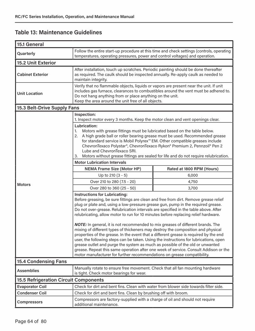
Page 64 of 80
Table 13: Maintenance Guidelines
15.1 General
Quarterly Follow the entire start-up procedure at this time and check settings (controls, operating temperatures, operating pressures, power and control voltages) and operation.
15.2 Unit Exterior
Cabinet ExteriorAfter installation, touch up scratches. Periodic painting should be done thereafter as required. The caulk should be inspected annually. Re-apply caulk as needed to maintain integrity.
Unit Location
Verify that no flammable objects, liquids or vapors are present near the unit. If unit includes gas furnace, clearances to combustibles around the vent must be adhered to.Do not hang anything from or place anything on the unit.Keep the area around the unit free of all objects.
15.3 Belt-Drive Supply Fans
Motors
Inspection:1. Inspect motor every 3 months. Keep the motor clean and vent openings clear.Lubrication:1. Motors with grease fittings must be lubricated based on the table below.2. A high grade ball or roller bearing grease must be used. Recommended grease
for standard service is Mobil Polyrex™ EM. Other compatible greases include ChevronTexaco Polystar®, ChevronTexaco Rykon® Premium 2, Pennzoil® Pen 2 Lube and ChevronTexaco SRI.
3. Motors without grease fittings are sealed for life and do not require relubrication.Motor Lubrication Intervals
NEMA Frame Size (Motor HP) Rated at 1800 RPM (Hours)Up to 210 (3 - 5) 6,000
Over 210 to 280 (7.5 - 20) 4,750Over 280 to 360 (25 - 50) 3,700
Instructions for Lubricating:Before greasing, be sure fittings are clean and free from dirt. Remove grease relief plug or plate and, using a low-pressure grease gun, pump in the required grease. Do not over-grease. Relubrication intervals are specified in the table above. After relubricating, allow motor to run for 10 minutes before replacing relief hardware.
NOTE: In general, it is not recommended to mix greases of different brands. The mixing of different types of thickeners may destroy the composition and physical properties of the grease. In the event that a different grease is required by the end user, the following steps can be taken. Using the instructions for lubrications, open grease outlet and purge the system as much as possible of the old or unwanted grease. Repeat this same operation after one week of service. Consult Addison or the motor manufacturer for further recommendations on grease compatibility.
15.4 Condensing Fans
Assemblies Manually rotate to ensure free movement. Check that all fan mounting hardwareis tight. Check motor bearings for wear.
15.5 Refrigeration Circuit ComponentsEvaporator Coil Check for dirt and bent fins. Clean with water from blower side towards filter side.Condenser Coil Check for dirt and bent fins. Clean by brushing off with broom.
Compressors Compressors are factory-supplied with a charge of oil and should not require additional maintenance.
RC/FC Series Installation, Operation, and Maintenance Manual

Page 65 of 80
Table 13: Maintenance Guidelines, Cont.
15.6 Condensate Drain Pan and Drain
Assembly Check for blockages. Clean as necessary with mixture of 1/2 cup [0.1 L] bleach and 1 gallon [1.9 L] warm water if signs of mold or algae are present.
15.7 DampersDampers Check and clean blades.Damper Motor/Linkages Verify that all damper linkages move freely. Lubricate if necessary.
15.8 Electric Heater Wiring and Wiring Connections
AssemblyCheck all wiring connections. Tighten as necessary.Check internal wiring. Replace as necessary with type THHN 221°F (105°C), 600V, 16 gauge wire or equivalent.
Control Panel Check heater control panel for dust/dirt and moisture. Clean as necessary.
Heating Elements
Check heating elements for dust/dirt build-up and/or broken elements. Replace elements and /or clean elements with low pressure air as necessary.Check element male/female chassis insulators for breaks and/or cracks. Replace as necessary.Check element support frame insulators. Replace missing or broken insulatorsas necessary.
15.9 Filters
Assemblies Filters should be checked for dirt restriction on a monthly basis (or as required). Replace filters with filters of equal specification when they appear dirty.
RC/FC Series Installation, Operation, and Maintenance Manual
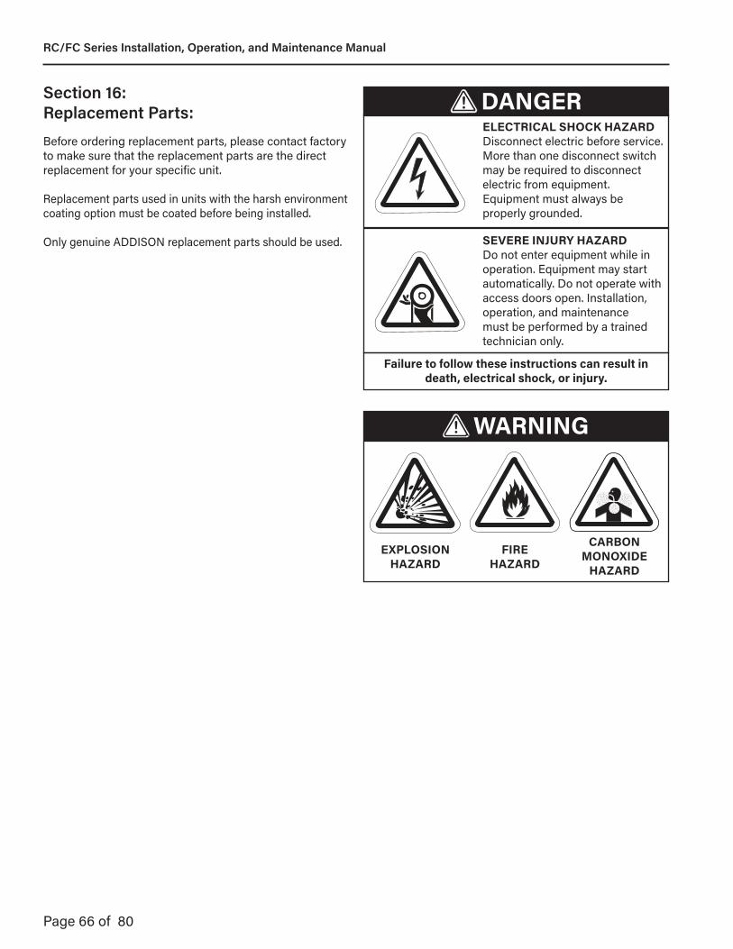
Page 66 of 80
Section 16: Replacement Parts:Before ordering replacement parts, please contact factory to make sure that the replacement parts are the direct replacement for your specific unit.
Replacement parts used in units with the harsh environment coating option must be coated before being installed.
Only genuine ADDISON replacement parts should be used.
DANGERELECTRICAL SHOCK HAZARDDisconnect electric before service. More than one disconnect switch may be required to disconnect electric from equipment. Equipment must always be properly grounded.
SEVERE INJURY HAZARDDo not enter equipment while in operation. Equipment may start automatically. Do not operate with access doors open. Installation, operation, and maintenance must be performed by a trained technician only.
Failure to follow these instructions can result in death, electrical shock, or injury.
FIRE HAZARD
WARNING
EXPLOSION HAZARD
CARBON MONOXIDE
HAZARD
RC/FC Series Installation, Operation, and Maintenance Manual

Page 67 of 80
DANGERELECTRICAL SHOCK HAZARDDisconnect electric before service. More than one disconnect switch may be required to disconnect electric from equipment. Equipment must always be properly grounded.
SEVERE INJURY HAZARDDo not enter equipment while in operation. Equipment may start automatically. Do not operate with access doors open. Installation, operation, and maintenance must be performed by a trained technician only.
Failure to follow these instructions can result in death, electrical shock, or injury.
FIRE HAZARD
WARNING
EXPLOSION HAZARD
CARBON MONOXIDE
HAZARD
Section 17: Troubleshooting:The following tables outline typical unit troubleshooting techniques for each section of the system.
All installation and service of ADDISON® equipment must be performed by a contractor qualified in the installation and service of equipment sold and supplied by Addison and conform to all requirements set forth in the ADDISON® manuals and all applicable governmental authorities pertaining to the installation, service, operation and labeling of the equipment.
RC/FC Series Installation, Operation, and Maintenance Manual

Page 68 of 80
Problem Probable Cause Solution
Blower Motor Does Not Run
Damper limit switch not closed or inoperative Repair or replace switch
Motor thermal overloads tripped For tripped condition-resetFuses blown or missing ReplaceExternal power source lacking Have incoming power lines checkedMotor inoperative Repair or replace
Blower Motor Runs, But Fans Do Not Supply Enough Make-Up Air
Intake filters dirty Replace or clean
Obstruction in intake Check dampers for proper operationClear all intake passages of obstructions
Fan wheel loose on shaft Reposition and tightenAccess doors and panels not closed CloseExcessive discharge resistance from:Dirty filters in dischargeExternal dampers
Clean filters and/or readjust dampers
Excessive Fan Noise
Fan bearing ReplaceFan wheel loose on shaft Reposition and re-tighten
Fan wheel rubbing Loosen setscrews reposition coneand tighten
Fan wheel dirty CleanLoose duct Tighten or reinforceForeign article in fan or duct Remove
Table 14.1: Supply Fan
RC/FC Series Installation, Operation, and Maintenance Manual
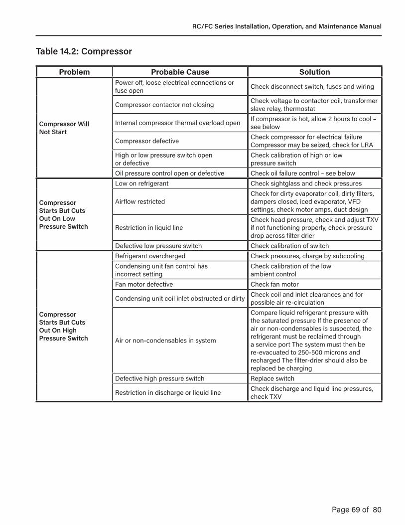
Page 69 of 80
Problem Probable Cause Solution
Compressor Will Not Start
Power off, loose electrical connections or fuse open Check disconnect switch, fuses and wiring
Compressor contactor not closing Check voltage to contactor coil, transformer slave relay, thermostat
Internal compressor thermal overload open If compressor is hot, allow 2 hours to cool – see below
Compressor defective Check compressor for electrical failureCompressor may be seized, check for LRA
High or low pressure switch open or defective
Check calibration of high or lowpressure switch
Oil pressure control open or defective Check oil failure control – see below
CompressorStarts But CutsOut On LowPressure Switch
Low on refrigerant Check sightglass and check pressures
Airflow restrictedCheck for dirty evaporator coil, dirty filters, dampers closed, iced evaporator, VFD settings, check motor amps, duct design
Restriction in liquid lineCheck head pressure, check and adjust TXV if not functioning properly, check pressure drop across filter drier
Defective low pressure switch Check calibration of switch
CompressorStarts But CutsOut On HighPressure Switch
Refrigerant overcharged Check pressures, charge by subcoolingCondensing unit fan control has incorrect setting
Check calibration of the low ambient control
Fan motor defective Check fan motor
Condensing unit coil inlet obstructed or dirty Check coil and inlet clearances and for possible air re-circulation
Air or non-condensables in system
Compare liquid refrigerant pressure with the saturated pressure If the presence of air or non-condensables is suspected, the refrigerant must be reclaimed through a service port The system must then be re-evacuated to 250-500 microns and recharged The filter-drier should also be replaced be charging
Defective high pressure switch Replace switch
Restriction in discharge or liquid line Check discharge and liquid line pressures, check TXV
Table 14.2: Compressor
RC/FC Series Installation, Operation, and Maintenance Manual

Page 70 of 80
Problem Probable Cause Solution
Compressor Cuts Out On Thermal Overload
Low voltage
Check incoming voltage leg-to-legAll three legs must be within 10% of the required voltage and the leg-to-three-leg average voltage variation must be less than 2% on each leg
Sustained high discharge pressure Check running amperage and conditions described under high discharge pressure
High suction and discharge pressures Check TXV setting, check for air in system
Defective compressor overload Allow compressor to cool for two hours if compressor is hot, recheck for open circuit
Defective run capacitor Check run capacitor for compressor and fan motor
Improper refrigerant charge Check subcoolingBearings or pistons too tight Check for low oil levelAllow time for compressor to cool Check dome temperature of compressor
Noisy Compressor
Scroll compressors are rotation sensitive Reverse wiring at disconnect switch may require blower be rechecked for rotation
Refrigerant overcharged Check pressures and subcooling
Excess or insufficient oil in compressor crankcase
Check oil level on hermetic compressors, check total equivalent feet of piping, add oil as recommended
Liquid floodback Check TXV setting, refrigerant overcharge refrigerant circuit problem
Tubing rattle Dampen by taping or clamping, bend tubing away from contact where possible
Compressor defective Replace compressor
Table 14.2: Compressor, Cont.
RC/FC Series Installation, Operation, and Maintenance Manual
Page 71 of 80
Problem Probable Cause Solution
Noisy Operation
Air noise Check ductwork Air Velocity too high
Chattering contactorCheck for adequate control voltage, check for shorts or breaks, check thermostat, check contactor points
Tubing rattle Dampen by taping or clamping, bend tubing away from contact where possible
High Suction Pressure
Excessive load on evaporator coil Check for high entering wet bulb temperature Check for excessive airflow
Broken compressor valves Scroll compressors do not have valves
Scroll compressors should not be pumped down below 5 PSI
Compressor is unloaded Recalibrate unloader pressure switchLeaking check valve Check temperature across check valveExpansion valve not secured to suction line or TXV defective Check the TXV, ensure bulb is insulated
High DischargePressure
TXV setting Check TXV setting and calibrate superheatAir inlet to condensing unit dirty or obstructed
Check for proper clearances and possible air recirculation
Condensing unit fan, motor defective Check condensing unit fan motor and run capacitor
Condensing unit fan control has incorrect setting
Check calibration of low ambient head pressure control
Suction PressureToo Low
Refrigerant undercharge Check pressures and subcooling
Blower running backwards Interchange any two wires connectedto motor
Defective or improperly adjusted expansion valve Check superheat and adjust TXV
Dirty filter Check filter and evaporator coilToo little airflow or low entering air temperature
Check airflow and entering air wetbulb conditions
Restriction in suction or liquid line Check refrigerant circuit for restriction
Head PressureToo Low
Insufficient refrigerant charge Check subcooling, check for leakDefective or improperly adjusted expansion valve Check superheat and adjust TXV
Low suction pressure See above – suction pressure too lowCondensing unit fan control setting Check calibration of low ambient controlCompressor defective See above – high suction pressure
Liquid Line Too HotRefrigerant undercharged See above – high discharge pressureHigh discharge pressure Restriction upstream at point of frosting
Suction Line FrostingInsufficient evaporator airflow Check airflow, check fan VFD,
closed dampersRestriction in suction or liquid line Restriction upstream at point of frostingMalfunctioning or defective expansion valve Check bulb of TXV
Table 14.3: Refrigeration Circuit
RC/FC Series Installation, Operation, and Maintenance Manual
Page 72 of 80
Problem Probable Cause Solution
CompressorShort Cycles
Thermostat location or malfunction Check thermostat, check heat anticipator setting
Improper refrigerant charge Check subcooling, verify superheatDefective high or low pressure control Check high or low pressure switchCycling on internal overload Possible tight bearings – see aboveDefective expansion valve Check TXV and superheatPoor air distribution Check ductwork for recirculationHigh discharge pressure See above – high discharge pressureLeaking discharge valves in compressor See above – high suction pressure
Running Cycle Too Long Or UnitOperates Continuously
Refrigerant undercharged Check subcoolingDirty filter or evaporator coil Check filter, coil and airflowDirty or clogged condensing unit coil Check coil and airflow
Air or other non-condensables in system Check equalized high side pressure with equivalent outdoor temperature
Defective compressor See above – high suction pressureRestriction in suction and liquid line Check for restrictions in refrigerant circuit
Control contacts stuck Check thermostat, shorts in wiring, slave relay compressor contactor
Supply Air TemperatureToo High
Refrigerant undercharge or leak in system Check subcooling and check for leaksEvaporator plugged with dirt or ice Check evaporator, airflow and filterImproperly adjusted or defective expansion valve
Check superheat and adjust TXV, check bulb
Defective compressor Check compressor for proper operationHigh discharge pressure See above- high discharge pressureAirflow is too high Check external static pressure
Supply Air TemperatureToo Low
Airflow is too low
Check evaporator coil, filter, check for closed dampers, grills, drive for loose parts, belts, misalignment, check externalstatic pressure
Return air temperature too low Check entering air wet bulb conditions
Blower MotorNot Running
Improper wiring Check wiring diagramDefective motor Check motor controllerDefective thermostat or control circuit Check “R” and “G” CircuitMotor off on overload protector Allow motor to cool, check amperage
Table 14.3: Refrigeration Circuit, Cont.
RC/FC Series Installation, Operation, and Maintenance Manual
Page 73 of 80
Problem Probable Cause Solution
No Fan Operation
No 24V control voltage Check for 24 VAC at control
No input pressure to control
Check alignment of capillary fitting Schrader valve depressor must depress Schrader valve enough to allow pressure into capillary
Bad fan motor
Disconnect power, when P266 is used, place a jumper from L1 to M1 and connect power, if fan does not start, motor is bad and should be replaced
Pressure transducer problem
Disconnect 6 pin connector from right side of control, place a jumper wire between third pin from the top and bottom pin on the control (not the cable) If fan goes to full speed, check for input pressure If it has been determined there is adequate pressure, the transducer is bad and the control must be replaced
Fan Stops When Pressure Reached The High End Of The Operating Range
Control is not wired correctly See wiring diagrams
No Fan Modulation (On-Off Operation) Control is not wired correctly See wiring diagrams
Fan Starts At Full Speed Control is not wired correctly See wiring diagrams
Erratic Fan OperationControl is not wired correctly See wiring diagramsDirty or blocked condensing unit coil Clean condensing unit coil
Erratic Pressure Control
Defective regulator Replace defective part
Dirt causing regulator to bind Disassemble regulator and clean internal parts Install strainer
Power source to hot gas solenoid or operation of the solenoid is intermittent
Determine if problem is caused by supply voltage, solenoid or excessive MOPD, make changes necessary to correct problem
Regulator LeakageDirt in regulator causing seat to remain open Clean regulator Install strainerWorn or eroded seating surface on regulator Replace defective part
Regulator Hunting (Chattering) With Large FluctuationsIn Controlled Pressures
Regulator is oversized Contact Addison for correctly sized regulator
Regulator and liquid injection thermovalve have control interaction
Increase superheat setting, dampen bulb response by repositioning
Regulator and cylinder unloaders have control interaction
Increase differential between the controls by lowering the regulator’s setpoint
Table 14.4: Variable Speed Head Pressure Control
RC/FC Series Installation, Operation, and Maintenance Manual
Page 74 of 80
Problem Probable Cause Solution
Regulator Will Not Provide Pressure Control
Regulator seat is restricted Locate and remove stoppage, install strainerPressure adjusting stem is set at a point so high that suction pressure never reaches the setpoint
Re-adjust the regulator
Strainer clogged at the regulator inlet Locate and remove stoppageMOPD exceeded across the solenoid or loss of source voltage
Replace solenoid or troubleshoot the electrical problem
Solenoid coil burned out Replace coilWrong type of distributor for hot gas bypass to the evaporator
Install proper venture-flo type distributor for low pressure drop
Regulator Fails To Close
Dirt under seat of regulator Locate and remove stoppage, install strainer or filter drier
Diaphragm failure (leakage around the adjusting stem) Replace defective parts
Pressure adjusting stem is set at a point so high that suction never reaches the setpoint Re-adjust the regulator
Blocked external equalizer passage Locate and remove stoppage, install strainerWorn or eroded regulator seat Replace defective part
Table 14.4: Variable Speed Head Pressure Control, Cont.
RC/FC Series Installation, Operation, and Maintenance Manual

Page 75 of 80
Problem Probable Cause Solution
No Heat
No call for heat Check that the controls are set to call for heating
No power and control voltage to heater Check that heater has power andcontrol voltage
Faulty component Check components with continuity meter, replace as necessary
Not Enough HeatFaulty component
Check ampere draw is reasonably close to that on the heater data plate If more than 10% short, begin testing individual components, replace as necessary
Heat anticipator current draw too low, causing short cycling Check current draw
Heater Cycling on AutomaticLimit
Improper airflowCheck for obstructions to return air, loose or broken fan belt and clogged filters and/or evaporator coils
Faulty temperature limit switch Test and, if necessary, replaceOpen Secondary ProtectiveDevice
Stuck contactor Check contactor
Contactor ChatterImproper wiring Check wiringInsufficient transformer capacity Check transformer
Element Failure Corroded hardware and/or loose connections Check hardware
Table 14.5: Electric Heater
RC/FC Series Installation, Operation, and Maintenance Manual

Page 76 of 80
Section 18 Addison Warranty:The following is the Limited Warranty provided by Addison (a trade name of Addison HVAC LLC, herein “Seller”) to any customer (herein “Buyer”) for any goods and services (a “deliverable”):
1. 1. Limited Warranty. Seller provides such warranty as set forth in any instruction manual provided with the deliverable, or if there is no such warranty or instruction manual, Seller warrants to Buyer that such deliverable will be free from defects in material and workmanship (in either case the “Limited Warranty”). Except as expressly set forth in this section or specifically authorized by an executive officer of Seller in writing, the Limited Warranty is not transferable or assignable and any such transfer or assignment is void. If Buyer is authorized by Seller to be a reseller of deliverables that are goods or an installing contractor, the Limited Warranty may be passed through to Buyer’s customer, but Buyer shall not alter the Limited Warranty in any way. Notwithstanding the foregoing, if Buyer re-brands Seller’s deliverable or Seller, at Buyer’s request, brands the deliverable with a mark not owned by Seller, the Limited Warranty may not be transferred or assigned, and all claims under the Limited Warranty shall be made directly by Buyer to Seller and not by any customer of Buyer. The Limited Warranty does not cover service trips, service calls, costs of removing and reinstalling components and other labor charges or the cost of shipment of replacement parts. The Limited Warranty excludes damages due to (i) failure to install, operate or maintain deliverables as directed in any instruction manual provided or under applicable law or regulation, (ii) misuse, abuse, neglect or modification of a deliverable or any controls, in any way, (iii) improper service, use of replacement parts or accessories that are not specified by Seller, (iv) improper installation, or any relocation of a deliverable after initial installation, (v) incorrect supply, accident, fire, flood, acts of God or other casualty, (vi) use of a deliverable other than its intended purpose and normal usage, (vii) use of a deliverable in a corrosive atmosphere or any atmosphere containing contaminants, (viii) shipment of a deliverable (all claims must be filed with carrier), (ix) use of a deliverable in the vicinity of combustible or explosive materials, (x) any defect in a deliverable arising from a drawing, design, or specification supplied by or on behalf of Buyer, (xi) failure of parts, components, services or hook-ups not supplied by Seller, (xii) incompatibility with items not supplied by Seller, (xiii) a deliverable not properly installed by a qualified
contractor experienced in installing the deliverable, (xiv) inadequate air for combustion, (xv) improper or rapid cycling of the compressor. No warranty coverage is applicable if Buyer cannot prove original purchase date and required annual maintenance history, the data plate and/or serial number on any deliverable is removed, defaced, modified or altered in any way, or Seller is not permitted to inspect the damaged deliverable. Wear items or consumables such as belts, filters, coolant, refrigerant, etc. are not included under the Limited Warranty. The Limited Warranty does not cover the equipment and materials not manufactured by Seller; the warranty for those items shall be limited to only such warranty as that furnished by the manufacturer thereof as may properly be assigned to Buyer. No person other than an executive officer of Seller has authority to change or extend the terms of the Limited Warranty, and Buyer confirms that no other warranty terms have been extended by Seller or are applicable to the deliverables. Change or extensions to the terms of the Limited Warranty are binding only if confirmed in writing by Seller’s duly authorized executive officer.
2. Limitation on Warranties/Damages. Any claim under the Limited Warranty set forth in section 1 must be made within the following time periods or such claim is waived: (a) for compressors, the claim must be made within sixty (60) months from the date of purchase by Buyer; (b) for replacement parts, the claim must be made within the latter of twelve (12) months from the date of shipment by Seller or any Limited Warranty period remaining on the deliverable with which the replacement part is used or is intended to be used; (c) for all other deliverables, the claim must be made within twelve (12) months from the date of start-up or eighteen (18) months from the date of shipment by Seller, whichever occurs first. For all deliverables (other than replacement parts) that require installation and start-up, the otherwise applicable warranty period shall be extended by an additional four (4) months if (i) the installation and start-up is performed by a contractor on Seller’s current list of contractors who have successfully completed Seller’s current installation course for that deliverable and (ii) full details of the installation and start-up are provided to Seller at or prior to the time any warranty claim is made.
RC/FC Series Installation, Operation, and Maintenance Manual
Page 77 of 80
Except as set forth in these terms, Seller makes no representation or warranty of any type, express or implied, including any warranty of merchantability, warranty of fitness for a particular purpose or warranty of non-infringement or warranty arising from any course of dealing, course of performance or usage of trade. Seller will not under any circumstances, be liable for any special, indirect, punitive or consequential damages (even if Seller has been notified of the possibility of such damages) resulting from or related to a product including, without limitation, any loss of profits, or loss of opportunity. Some jurisdictions do not allow limitations on warranties or damages, so this limitation or exclusion may not apply to Buyer
3. Remedy. Seller’s sole obligation and Buyer’s exclusive remedy with respect to any deliverable, whether arising in contract, tort (including negligence), strict liability, breach of warranty or otherwise, is limited to Seller, at its discretion, replacing or repairing the defective deliverable, providing replacement parts or issuing Buyer a credit equal to the price paid to Seller for such defective deliverable, and in no event will Seller’s liability exceed the amounts actually received by Seller for any deliverable. This exclusive remedy shall not be deemed to have failed its essential purpose so long as Seller is willing and able to repair or replace a defective deliverable or parts thereof or, also at Seller’s option, to refund the price received by Seller for the defective deliverable, within a reasonable time after Buyer demonstrates that a defect exists in accordance with the terms and limitations of the Limited Warranty.
If you have questions, contact your installing professional. Should you need replacement parts or have additional questions, call or write:
Addison7050 Overland RoadOrlando, FL 32810Telephone: +1.407.292.4400Fax: +1.407.290.1329www.addison-hvac.com
RC/FC Series Installation, Operation, and Maintenance Manual

Page 78 of 80
Notes:
RC/FC Series Installation, Operation, and Maintenance Manual

Page 79 of 80
Revision Guide:Date: Page: Description: By:06 Feb 19 All First Published DS
RC/FC Series Installation, Operation, and Maintenance Manual
© Addison 2019
7050 Overland RoadOrlando, FL 32810
Tel.: 407-292-4400 ∙ Fax: 407-290-1329www.addison-hvac.com
DEDICATED OUTDOOR AIR SPECIALISTS
Part Number:AD-IOM-RCFC-001
Rev.: 06 Feb 2019DS
*AD-IOM-RCFC-001*


![Addison Underbridge Connection North Riverfront Trail · Addison Underbridge Connection ... ADDISON BRIDGE ii*ãiil ... 130815 Addison underbridge.ppt [Compatibility Mode] Author:](https://img.pdfslide.net/doc/110x75/5af3c6f57f8b9a74448bf133/addison-underbridge-connection-north-riverfront-trail-underbridge-connection-.jpg)