Embed Size (px)
Citation preview

Additive manufacturing for in situ repair of osteochondral defects
This article has been downloaded from IOPscience. Please scroll down to see the full text article.
2010 Biofabrication 2 035004
(http://iopscience.iop.org/1758-5090/2/3/035004)
Download details:
IP Address: 172.16.1.138
The article was downloaded on 10/09/2010 at 13:52
Please note that terms and conditions apply.
View the table of contents for this issue, or go to the journal homepage for more
Home Search Collections Journals About Contact us My IOPscience
IOP PUBLISHING BIOFABRICATION
Biofabrication 2 (2010) 035004 (12pp) doi:10.1088/1758-5082/2/3/035004
Additive manufacturing for in situ repairof osteochondral defectsDaniel L Cohen1, Jeffrey I Lipton1, Lawrence J Bonassar1,2 andHod Lipson1,3,4
1 Cornell University, Mechanical and Aerospace Engineering, Ithaca, NY, USA2 Cornell University, Biomedical Engineering, Ithaca, NY, USA3 Cornell University, Faculty of Computing and Information Science, Ithaca, NY, USA
E-mail: [email protected], [email protected], [email protected] and [email protected]
Received 27 April 2010Accepted for publication 6 August 2010Published 8 September 2010Online at stacks.iop.org/BF/2/035004
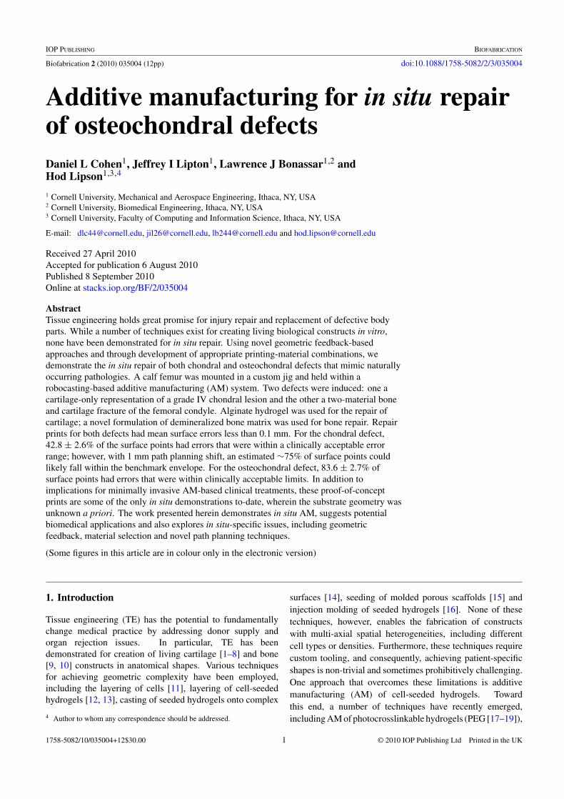
AbstractTissue engineering holds great promise for injury repair and replacement of defective bodyparts. While a number of techniques exist for creating living biological constructs in vitro,none have been demonstrated for in situ repair. Using novel geometric feedback-basedapproaches and through development of appropriate printing-material combinations, wedemonstrate the in situ repair of both chondral and osteochondral defects that mimic naturallyoccurring pathologies. A calf femur was mounted in a custom jig and held within arobocasting-based additive manufacturing (AM) system. Two defects were induced: one acartilage-only representation of a grade IV chondral lesion and the other a two-material boneand cartilage fracture of the femoral condyle. Alginate hydrogel was used for the repair ofcartilage; a novel formulation of demineralized bone matrix was used for bone repair. Repairprints for both defects had mean surface errors less than 0.1 mm. For the chondral defect,42.8 ± 2.6% of the surface points had errors that were within a clinically acceptable errorrange; however, with 1 mm path planning shift, an estimated ∼75% of surface points couldlikely fall within the benchmark envelope. For the osteochondral defect, 83.6 ± 2.7% ofsurface points had errors that were within clinically acceptable limits. In addition toimplications for minimally invasive AM-based clinical treatments, these proof-of-conceptprints are some of the only in situ demonstrations to-date, wherein the substrate geometry wasunknown a priori. The work presented herein demonstrates in situ AM, suggests potentialbiomedical applications and also explores in situ-specific issues, including geometricfeedback, material selection and novel path planning techniques.
(Some figures in this article are in colour only in the electronic version)
1. Introduction
Tissue engineering (TE) has the potential to fundamentallychange medical practice by addressing donor supply andorgan rejection issues. In particular, TE has beendemonstrated for creation of living cartilage [1–8] and bone[9, 10] constructs in anatomical shapes. Various techniquesfor achieving geometric complexity have been employed,including the layering of cells [11], layering of cell-seededhydrogels [12, 13], casting of seeded hydrogels onto complex
4 Author to whom any correspondence should be addressed.
surfaces [14], seeding of molded porous scaffolds [15] andinjection molding of seeded hydrogels [16]. None of thesetechniques, however, enables the fabrication of constructswith multi-axial spatial heterogeneities, including differentcell types or densities. Furthermore, these techniques requirecustom tooling, and consequently, achieving patient-specificshapes is non-trivial and sometimes prohibitively challenging.One approach that overcomes these limitations is additivemanufacturing (AM) of cell-seeded hydrogels. Towardthis end, a number of techniques have recently emerged,including AM of photocrosslinkable hydrogels (PEG [17–19]),
1758-5082/10/035004+12$30.00 1 © 2010 IOP Publishing Ltd Printed in the UK

Biofabrication 2 (2010) 035004 D L Cohen et al
thermoreversible gels (gelatin [20–25], pluronic [26], collagen[21, 26, 27]) and post-deposition ionically crosslinked alginatehydrogel [24, 25, 28].
These AM techniques, however, have only beendemonstrated for the fabrication of TE constructs in vitro.That is, none of these techniques have been employed in situ[29–31] directly on a wound site. Moreover, these approachesare not amenable to in situ AM because they rely on externalenvironmental cues, such as UV light, temperature and calciumavailability to initiate the phase change after deposition.For in situ applications, the environment cannot necessarilybe controlled, and the introduction of precise externalenvironmental cues within the body is likely unfeasible. Onetechnique, however, the deposition of alginate hydrogel withionic crosslinking initiated prior to deposition [32], does notrely upon external cues for phase change after deposition,and thus is compatible with in situ applications. In additionto finding compatible materials, other issues needed to beaddressed to enable in situ repair, such as imaging, registrationand path planning.
Even beyond the medical context, in situ AM has onlyrarely been demonstrated, and never in a generalized contextwithout a priori substrate-shape information, as conductedherein. In situ AM of thermocouples [30] and wire networks[33] has been demonstrated onto pre-existing objects ofcomplex geometry; however, in both of these cases thegeometry was known, i.e. hard-coded into the planningsequence. Generalized in situ AM, although potentiallypowerful, has likely been hampered by the lack of pre-existinggeometric feedback-based AM techniques/algorithms. Priorto this work, geometric feedback has only been used in limitedcases, such as stabilizing AM process parameters [34–36] andindividual droplet shapes [37]. However, geometric feedbackhad never been used for ascertaining substrate geometryin order to print onto pre-existing objects of unspecifiedshape. Furthermore, no techniques had been developed tohandle in situ-specific challenges, including path planning,materials formulation, image processing and geometric fidelitycharacterization.
Through the work presented herein, we demonstrated thein situ repair of a cylinder-shaped cartilage (i.e. chondral)defect as well as a geometrically complex two-material boneand cartilage (i.e. osteochondral) defect. These defectswere created on a calf femur to mimic naturally occurringpathologies. The chondral defect approximated a cylindricalcore created by surgeons during the OATS (osteoarticulartransfer system) surgical procedure in order to treat agrade IV chondral lesion. The second defect used herein,the osteochondral defect, approximated a severe complexfreeform fracture of the femoral condyle in which both boneand cartilage tissues were damaged.
In these cases, the defect-induced femur served asthe printing substrate and was mounted in a custom jigwithin the AM machine. Alginate hydrogel, with ioniccrosslinking initiated prior to deposition [32], was used forrepair of cartilage; bone was repaired with a novel formulationof demineralized bone matrix (DBM). AM planning wasconducted by CT scanning the bone before and after defect
creation, differencing of the two images and subsequentlyraster pathing the resultant geometry. Feature-based imageregistration was conducted to align the printing substratewithin the printer. Herein we demonstrate materials, hardwaremodifications, CT imaging and registration for the in situ repairof both chondral and osteochondral defects.
Potential clinical applications of this in situ AM techniqueare discussed in depth in section 4. These applicationsinclude orthopaedic repair that is minimally invasive and/orgeometrically patient-specific. With other material sets andthe appropriate seeded cells, this approach could potentiallybe extended to fields such as facial reconstruction and generaltrauma surgery.
2. Materials and methods
2.1. Alginate hydrogel preparation
Alginate hydrogels were prepared for printing, usingtechniques based on those described previously [32]. Thealginate solution was created by mixing low-viscosity,high G-content non-medical grade LF10/60 alginate (FMCBiopolymer, Drammen, Norway) with PBS at a concentrationof 20 mg mL−1. The CaSO4 crosslinker solution was createdat a concentration of 10 mg mL−1 in PBS. The alginate andcrosslinker solutions were combined in a 2:1 ratio and mixed150 times through a stopcock at 1 Hz. The mixed alginatehydrogel was loaded into a 10 mL syringe (EFD Inc., EastProvidence, RI) and allowed to cure for at least 10 min beforeuse in any printing or experimentation.
2.2. Demineralized bone matrix paste preparation
The basis of the printable bone paste was demineralizedbone matrix (DBM) in a purified powdered gelatin carrier(BioSetTM; Regeneration Technologies Inc., Alachua, FL).The manufacturer specifies 38% Bioset DBM-gelatin powderin water by weight. The paste is prepared by mixing theBioset DBM-gelatin powder with water through a two-portLuer-lok connector by walking the syringes back-and-forth inunison ten times. Even though the largest standard-diameterdeposition tip of the AM machine (1.50 mm diameter × 12 mmlong straight barrel) was used for initial material calibration,the DBM paste was still too viscous to be extruded. Ifthe tip were any larger, even though it would reduce theassociated extrusion force, the resultant print resolution wouldbe inadequate for the repair of millimeter-scale defects.
We conducted a material tuning experiment in orderto find an appropriate powder–water composition that waslow viscosity enough for extrusion but high viscosityenough for the printed material to retain its shape post-deposition. Three formulations were tested: the manufacturer-specified formulation (38% DBM-gelatin powder in water byweight) and two others with higher concentrations of water(34% and 30% DBM-gelatin powder in water by weight).Three properties were measured for each tested formulation:minimum extrusion force, sag and work life.
The minimum extrusion force was the force requiredto induce material flow through the deposition tip. The
2

Biofabrication 2 (2010) 035004 D L Cohen et al
Figure 1. Femoral printing substrate. The femur was set verticallyinto a plastic pipe fitting. The pipe fitting screwed directly into theprinter’s hot-swappable base tray.
AM machine’s material bay (i.e. a disposable syringe, seesection 2.6) was loaded with paste, held vertically on a digitalscale and the force at which flow began was recorded. Sag wasdetermined by manually extruding 10 mm tall, 6 mm diametercylinders and measuring the height difference over the first15 min. Work life was determined by measuring the elapsedtime before the previously determined minimum extrusionforce no longer induced paste flow.
2.3. Harvest and preparation of the femoral printingsubstrate
The printing substrate for the experiments presented hereinwas the distal end of a bovine femur. The leg of a sacrificed 1-to 3-day-old calf was dissected to isolate the femur. Muscularand connective tissues were removed while maintaining thegeometric integrity of the femoral condyles. The isolatedfemur was placed in boiling water for 20 min in order topreserve the bone. The femur was then cut halfway downthe shaft and vertically set in molding plaster (US GypsumCompany, Chicago, IL) within a PVC flange (figure 1). Thebone–flange assembly was mounted on a removable acrylictray and inserted into the printer.
2.4. CT imaging of the femoral printing substrate
CT images were collected on a 16-slice Toshiba AquilionLB. Volumetric data were collected in 0.5 mm segments andreconstructed using standard Toshiba-CT bone and soft tissuealgorithms (figure 2).
2.5. Creation of defects in the femoral condyles
Defects were created on the surface of the femoral printingsubstrate by a veterinary orthopaedic surgeon to mimic
Figure 2. CT image of the femur and its mounting jig.
pathological cases. Two of these defects were used for printingexperimentation (figure 3). The first induced defect, hereinreferred to as ‘case 1’ or the ‘chondral defect’, simulated agrade IV lesion of the articular cartilage on the medial femoralcondyle (figure 4). A grade IV lesion is one in which the tearof the cartilage goes all the way down to the underlying bonesurface, but does not extend into the bone. In order to createthis defect, a 16 mm diameter circular punch was used to coreout the condyle ∼4 mm downward to the bone surface.
The second defect, herein referred to as ‘case 2’ or the‘osteochondral defect’, was a first-order approximation of afracture in which a portion of the lateral femoral condylesheared off (figure 4). In the severe fracture scenario, thecartilage cap breaks off as well as some of the underlyingbone tissue. This two-tissue defect was created by using ascalpel to slice transversely to the condyle. The cut was made∼4 down from the distal end of the condyle and extended∼1 mm down into the underlying bone. To increase theseverity of the simulated injury, the bone tissue was furtherresected with a curette by carving out a ∼4 mm deep dome-shaped cavity.
2.6. Additive manufacturing system
A Fab@Home open-source, open-architecture AM systemwas used for the experiments presented herein [38](figure 5). This system, which was designed and deployed byour lab, comprised a laser cut acrylic chassis with a three-axisgantry motion system. Each axis was belt-driven and actuatedby Snap MotorsTM, which are dc-geared servo motors (JRKerr LLC., Berkeley, CA). Communication and motion wascoordinated by a USB-interfaced Snap HubTM, which is partof the Snap MotorTM system (JR Kerr LLC, Berkeley, CA).The open-source control software was written by our lab, and,along with the hardware design files, is freely available atwww.fabathome.org.
The standard Fab@Home design was modified in orderto allow for easy swapping of the printing substrate. TheFab@Home’s traditional base was upgraded to a custom
3

Biofabrication 2 (2010) 035004 D L Cohen et al
(a) (b)
(c)
Figure 3. Femoral printing substrate with induced chondral and osteochondral defects. (a) Overview of four defect sites. Two of these siteswere used for experimentation. (b) Close-up view of chondral defect site. A cartilage disc was removed exposing the underlying bonesurface. (c) Close-up view of osteochondral defect site. A bone sliver was removed and the underlying bone was also cored out.
Figure 4. Diagram of knee anatomy. The femur bears substantialload during normal usage. Chondral lesions and osteochondralfractures could potentially develop on the femur–tibia interface.Medical Illustration Copyright © 2010 Nucleus Medical Media, AllRights Reserved. www.nucleusinc.com
hot-swappable cartridge-style base plate (figure 6). Acrylictrays, 190 mm by 225 mm, were placed in the recess of
Figure 5. Fab@Home AM system. The Fab@Home AM system isan open-source, open-architecture platform. The material-filledsyringes insert into the deposition tool, and a servo motor pushesupon the plunger to extrude material through the Luer-loktip.
4

Biofabrication 2 (2010) 035004 D L Cohen et al
Figure 6. The standard base plate was modified to accommodatehot-swappable snap-in trays. The easy removal of printing parts isan important feature for enablement of in situ printing. Once thepart is registered, if the machine needed to be serviced, theremovable tray allowed for service without registration loss.
Figure 7. The laser distance sensor was mounted behind thedeposition tool.
the Fab@Home’s modified base plate and secured by aninterference fit. This feature is an important adaptation forin situ AM applications as it enables parts to be removed forinspection and replaced without the loss of spatial registration.
Another modification was made to accommodate a laserdistance sensor (OADM12 Laser; Baumer Ltd, Southington,CT). The laser sensor was mounted in between the Y-axiscarriage and the deposition tool (figure 7). This sensor hada 104 mm range and a distance measurement resolution of0.12 mm. The laser was used for measuring the geometricfidelity of printed constructs post-print by scanning the printerworkspace.
2.7. Path planning for in situ AM
The CT images of the femoral printing substrate were usedfor AM path planning. One CT scan before the creation
of the defects and a second scan afterward were importedin Mimics V12 (Materialise Group, Leuven, Belgium) asDICOM files and converted into 3D solid models. Morespecifically, during this conversion, the bone and cartilagetissues were isolated by creating a mask that thresholded theintensity values between −906 and 3071 Hounsfields, whichcorresponded to the tissues of interest. These values weredetermined by iteratively modifying the intensity thresholdsand ensuring complete inclusion of the target constructs whileexclusion of background noise, such as out-of-scope tissuesand environmental features. To further remove image noise,a region-growing algorithm was employed where the femur’scentroid served as the seed location and neighboring voxelswithin the threshold intensity range were included in the dataset. The thresholded, region-grown mask was then convertedto a 3D mesh, which was exported as an STL file.
A model of the defect was created by applying a Booleansubtraction operator to the ‘before’ and ‘after’ STL files. This‘differenced’ STL file was imported into the Fab@Home’sopen-source control software in order to create the path planof the target print geometry. A layer-wise raster path-planningalgorithm was employed. Registration of the femoral printingsubstrate within the printer was achieved by setting the 3Dmodel’s X–Y origin to the center of a known feature, in thiscase, the (+X, +Y) flange mounting bolt. During each print,the laser beam was used to register the coordinate systems byaligning the beam with the known feature (i.e. the bolt) andadding the known X–Y offset between the laser and depositiontip.
2.8. Geometric fidelity characterization
Geometric fidelity was both qualitatively and quantitativelycharacterized. During visual inspections, key observedcharacteristics included surface texture, similarity of theoverall shape compared to the intended geometry and thepresence of point defects such as missing material. In additionto visually inspecting constructs, each printed object was laserscanned (0.3 mm X–Y resolution, 0.12 mm height resolution).The resultant height data were converted into a 3D solid inStudio V11 (Geomagic Inc., Research Triangle Park, NC)and exported as an STL file. The file was then importedinto Qualify V11 (Geomagic Inc., Research Triangle Park,NC) which performed 3D geometric fidelity calculations,comparing the printed geometry to the intended target shape asspecified by the CT image of the pre-damage femur. The errorcalculated was the 3D error between the surface of the actualgeometry and the intended geometry (nearest point betweenthe surfaces). Note that all values in this paper are reported asmean ± standard deviation.
2.9. Benchmarking—determination of clinically allowablegeometric errors
In order to place the measured geometric errors within aclinical context, the repair-print errors were compared toallowable surgical tolerances established in prior literature.Each defect’s measured geometric error was compared totolerances of the medical procedure that best matched
5
Biofabrication 2 (2010) 035004 D L Cohen et al
(a) (b)
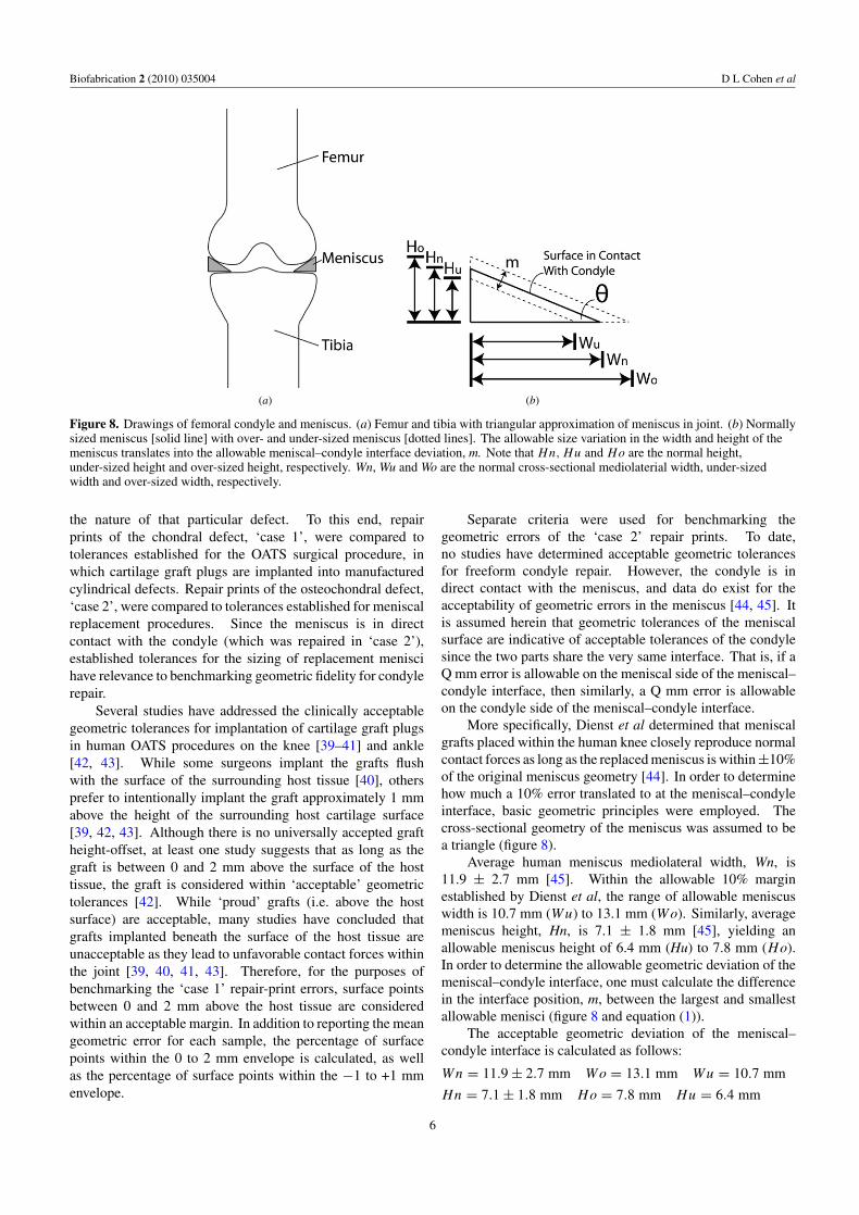
Figure 8. Drawings of femoral condyle and meniscus. (a) Femur and tibia with triangular approximation of meniscus in joint. (b) Normallysized meniscus [solid line] with over- and under-sized meniscus [dotted lines]. The allowable size variation in the width and height of themeniscus translates into the allowable meniscal–condyle interface deviation, m. Note that Hn, Hu and Ho are the normal height,under-sized height and over-sized height, respectively. Wn, Wu and Wo are the normal cross-sectional mediolaterial width, under-sizedwidth and over-sized width, respectively.
the nature of that particular defect. To this end, repairprints of the chondral defect, ‘case 1’, were compared totolerances established for the OATS surgical procedure, inwhich cartilage graft plugs are implanted into manufacturedcylindrical defects. Repair prints of the osteochondral defect,‘case 2’, were compared to tolerances established for meniscalreplacement procedures. Since the meniscus is in directcontact with the condyle (which was repaired in ‘case 2’),established tolerances for the sizing of replacement meniscihave relevance to benchmarking geometric fidelity for condylerepair.
Several studies have addressed the clinically acceptablegeometric tolerances for implantation of cartilage graft plugsin human OATS procedures on the knee [39–41] and ankle[42, 43]. While some surgeons implant the grafts flushwith the surface of the surrounding host tissue [40], othersprefer to intentionally implant the graft approximately 1 mmabove the height of the surrounding host cartilage surface[39, 42, 43]. Although there is no universally accepted graftheight-offset, at least one study suggests that as long as thegraft is between 0 and 2 mm above the surface of the hosttissue, the graft is considered within ‘acceptable’ geometrictolerances [42]. While ‘proud’ grafts (i.e. above the hostsurface) are acceptable, many studies have concluded thatgrafts implanted beneath the surface of the host tissue areunacceptable as they lead to unfavorable contact forces withinthe joint [39, 40, 41, 43]. Therefore, for the purposes ofbenchmarking the ‘case 1’ repair-print errors, surface pointsbetween 0 and 2 mm above the host tissue are consideredwithin an acceptable margin. In addition to reporting the meangeometric error for each sample, the percentage of surfacepoints within the 0 to 2 mm envelope is calculated, as wellas the percentage of surface points within the −1 to +1 mmenvelope.
Separate criteria were used for benchmarking thegeometric errors of the ‘case 2’ repair prints. To date,no studies have determined acceptable geometric tolerancesfor freeform condyle repair. However, the condyle is indirect contact with the meniscus, and data do exist for theacceptability of geometric errors in the meniscus [44, 45]. Itis assumed herein that geometric tolerances of the meniscalsurface are indicative of acceptable tolerances of the condylesince the two parts share the very same interface. That is, if aQ mm error is allowable on the meniscal side of the meniscal–condyle interface, then similarly, a Q mm error is allowableon the condyle side of the meniscal–condyle interface.
More specifically, Dienst et al determined that meniscalgrafts placed within the human knee closely reproduce normalcontact forces as long as the replaced meniscus is within ±10%of the original meniscus geometry [44]. In order to determinehow much a 10% error translated to at the meniscal–condyleinterface, basic geometric principles were employed. Thecross-sectional geometry of the meniscus was assumed to bea triangle (figure 8).
Average human meniscus mediolateral width, Wn, is11.9 ± 2.7 mm [45]. Within the allowable 10% marginestablished by Dienst et al, the range of allowable meniscuswidth is 10.7 mm (Wu) to 13.1 mm (Wo). Similarly, averagemeniscus height, Hn, is 7.1 ± 1.8 mm [45], yielding anallowable meniscus height of 6.4 mm (Hu) to 7.8 mm (Ho).In order to determine the allowable geometric deviation of themeniscal–condyle interface, one must calculate the differencein the interface position, m, between the largest and smallestallowable menisci (figure 8 and equation (1)).
The acceptable geometric deviation of the meniscal–condyle interface is calculated as follows:
Wn = 11.9 ± 2.7 mm Wo = 13.1 mm Wu = 10.7 mm
Hn = 7.1 ± 1.8 mm Ho = 7.8 mm Hu = 6.4 mm
6

Biofabrication 2 (2010) 035004 D L Cohen et al
Table 1. DBM paste characteristics. Printing characteristics of theDBM paste for three different formulations with variousconcentrations of water, n = 5. The pastes were assessed forminimum extrusion force, sag and work life.
Concentrationof DBM-Gelatin Minimum Sag (% Workpowder in water extrusion of initial lifeby weight (%) force (grams) height) (minutes)
38 3800 ± 450 3 ± 2 234 1900 ± 180 2 ± 2 1530 740 ± 80 25 ± 8 25
m = cos φ(Ho − Hu)
=(
Wn√Wn2 + Hn2
)(Ho − Hu) = 1.2 mm. (1)
Based on the human meniscus dimensions above, themaximum allowable geometric deviation of the meniscal–condyle interface (i.e. the allowable surface error of thecondyle), is an absolute range of 1.2 mm or ±0.6 mm relativeto the intended surface (equation (1)). Based on this reasoning,the geometric fidelity criterion for ‘case 2’, is ±0.6 mm relativeto the intended surface.
3. Results
3.1. Tuning of DBM paste formulation
Three different formulations of DBM paste were tested fortheir printing properties (n = 5): 38%, 34% and 30% DBM-gelatin powder in water by weight. The 38% formulation had aminimum extrusion force of 3800 ± 450 grams of force (note:values reported herein are mean ± standard deviation). The34% and 30% formulations had substantially lower minimumextrusion forces of 1900 ± 180 and 740 ± 80 grams of force,respectively. Only the 34% and 30% formulations fell withinthe Fab@Home’s deposition force limit of ∼2500 grams offorce.
The 38% and 34% formulations exhibited similar sagcharacteristics of 3 ± 2% and 2 ± 2% of the initial part height,respectively. The 30% paste, however, exhibited drasticallygreater sag at 25 ± 8%. While the sag was recorded over15 min, the majority of the sagging (most notably for the 30%formulation) occurred within the first 30 s after extrusion.
The work life of the 38% formulation was 2 min. Theformulations with higher concentrations of water exhibitedextended work lives. The 34% paste had a work life of 15 minand the 30% paste exhibited a work life of approximately25 min.
The 34% DBM-gelatin powder in water by weightformulation was selected for the subsequent experiments(table 1). This composition yielded the only acceptablecombination of minimum extrusion force and material sag.The 38% formulation exceeded the Fab@Home AM system’s
maximum deposition tool force, while the 30% formulationexhibited unacceptably poor sag characteristics.
3.2. Case 1: chondral defect
The CT scans from before and after the defect creation wereprocessed and differenced in order to create a model of thedefect (i.e. the target printing geometry). This geometrywas a cylindrical plug that matched the void present in thefemoral condyle (figure 9). The 3D model was path-plannedin Fab@Home software, and the print was conducted five timesto collect sufficient geometric fidelity data.
Alginate hydrogel was used as the ink for the repair ofthis cartilage-only defect. The gel was printed through a0.84 mm inner diameter ×31 mm long tapered syringe tip(EFD Inc., East Providence, RI). The printing parametersfor alginate were determined through separate calibrationexperiments in prior work [32]. The key parameters were0.8 mm path width, 0.71 mm path height and 10 mm s−1
deposition tool traverse rate.The gel construct was printed directly into the defect
cavity in situ five separate times. After each print, the constructwas visually inspected to qualitatively assess geometricfidelity, laser scanned for quantitative analysis, and thenthe construct was completely removed in preparation forthe following print within the same defect-cavity. Across thefive prints, the printed alginate hydrogel had a smooth surfacetexture. Furthermore, the printed geometry closely matchedthe intended geometry as specified by the CT scan before–after differencing process. The sides of the printed plug werecongruent with the perimeter of the induced chondral defect.Also, the top surface of the printed construct matched thecontour of the condyle (figure 9).
The average of the mean error was 0.0 ± 0.2 mm, n = 5(figure 10). Across the five prints, 42.8 ± 2.6% of thesurface points were within the 0 to +2.0 mm error envelope.However, 75.6 ± 7.6% of the surface points fell between −1.0and +1.0 mm.
3.3. Case 2: osteochondral defect
As in case 1, the CT scans from before and after the defectcreation were processed and used for path planning. Unlikecase 1, however, the case 2 defect comprised two materials:bone and cartilage. Alginate was again used for cartilagerepair; however, the DBM paste was used for the bone portionof the defect.
During path planning, the 3D mesh of the targetosteochondral construct was segmented into separate boneand cartilage geometric meshes through manual slicing. Thismanual slicing process was guided by the CT data whichdelineated between the two tissues according to the imageintensities (related to tissue densities).
The resultant print geometry was a dome-shaped boneplug covered by a cylindrical cartilage cap (figure 11). Asbefore, the alginate hydrogel was printed through a 0.84 mminner diameter ×31 mm long tapered syringe tip (EFD Inc.,East Providence, RI). The same printer parameters were usedas in case 1. The DBM paste was printed through a 1.50 mm
7

Biofabrication 2 (2010) 035004 D L Cohen et al
(a) (b)
(c)
Figure 9. Repair of chondral defect. (a) CT scan of the femur with the chondral defect on the top surface. (b) Chondral defect before repair.(c) Chondral defect after repair.
Figure 10. Top-view error plot of chondral defect. The laser scan ofthe printed surface was compared to the pre-damage CT scanreference geometry. Colors correspond to error magnitude.
diameter ×12 mm long straight-barrel tip (EFD Inc., EastProvidence, RI), which as described above, was the largesttip that would still provide adequate print resolution. Thekey printer parameters for the DBM paste were 1.65 mm path
width, 1.3 mm path height and 10 mm s−1 deposition tooltraverse rate. These parameters were determined largely bythe selected tip diameter. The specific values were optimizediteratively by fixing the extrusion rate and sweeping through arange of 1–25 mm s−1 tool traverse speed until continuousmaterial streams were produced. As in case 1, the printwas conducted five times in situ to collect geometric fidelitydata.
Since this print was an assembly of two constructs, theDBM portion of the print was visually inspected mid-print (i.e.before the alginate deposition). The printed bone construct hada rough surface texture. Its surface profile, however, closelymatched the intended surface contour of the substrate’s bonetissue. The bone construct was also laterally congruent withthe walls of the bone cavity.
Just as in case 1, the print was conducted five separatetimes within the same defect-cavity. In between prints thegeometric fidelity data was captured and then the printed gelwas completely removed in preparation for the following print.The printed alginate hydrogel had a smooth surface texture andhad a similar geometric fidelity to the alginate prints in case1. Again, the printed geometry closely matched the intendedgeometry and the parts were laterally congruent with the defectboundaries. The contour of the 3D freeform alginate constructclosely resembled the original pre-defect contour.
8
Biofabrication 2 (2010) 035004 D L Cohen et al
(a) (b)
(c) (d)
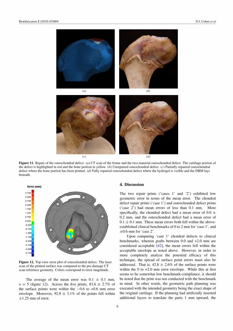
Figure 11. Repair of the osteochondral defect. (a) CT scan of the femur and the two-material osteochondral defect. The cartilage portion ofthe defect is highlighted in red and the bone portion in yellow. (b) Unrepaired osteochondral defect. (c) Partially repaired osteochondraldefect where the bone portion has been printed. (d) Fully repaired osteochondral defect where the hydrogel is visible and the DBM laysbeneath.
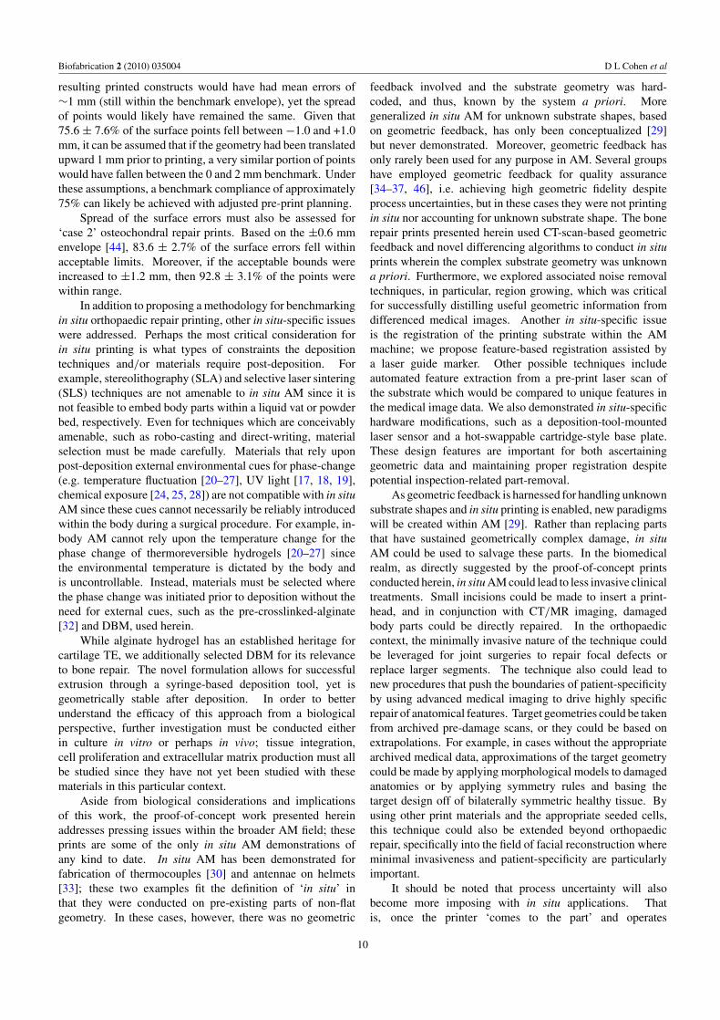
Figure 12. Top-view error plot of osteochondral defect. The laserscan of the printed surface was compared to the pre-damage CTscan reference geometry. Colors correspond to error magnitude.
The average of the mean error was 0.1 ± 0.1 mm,n = 5 (figure 12). Across the five prints, 83.6 ± 2.7% ofthe surface points were within the −0.6 to +0.6 mm errorenvelope. Moreover, 92.8 ± 3.1% of the points fell within±1.25 mm of error.
4. Discussion
The two repair prints (‘cases 1’ and ‘2’) exhibited lowgeometric error in terms of the mean error. The chondraldefect repair prints (‘case 1’) and osteochondral defect prints(‘case 2’) had mean errors of less than 0.1 mm. Morespecifically, the chondral defect had a mean error of 0.0 ±0.2 mm, and the osteochondral defect had a mean error of0.1 ± 0.1 mm. These mean errors both fell within the above-established clinical benchmarks of 0 to 2 mm for ‘case 1’, and±0.6 mm for ‘case 2’.
Upon comparing ‘case 1’ chondral defects to clinicalbenchmarks, wherein grafts between 0.0 and +2.0 mm areconsidered acceptable [42], the mean errors fell within theacceptable envelope as noted above. However, in order tomore completely analyze the potential efficacy of thistechnique, the spread of surface point errors must also beaddressed. That is, 42.8 ± 2.6% of the surface points werewithin the 0 to +2.0 mm error envelope. While this at firstseems to be somewhat low benchmark-compliance, it shouldbe noted that the print was not conducted with the benchmarkin mind. In other words, the geometric path planning wasexecuted with the intended geometry being the exact shape ofthe original cartilage. If the planning had artificially insertedadditional layers to translate the parts 1 mm upward, the
9
Biofabrication 2 (2010) 035004 D L Cohen et al
resulting printed constructs would have had mean errors of∼1 mm (still within the benchmark envelope), yet the spreadof points would likely have remained the same. Given that75.6 ± 7.6% of the surface points fell between −1.0 and +1.0mm, it can be assumed that if the geometry had been translatedupward 1 mm prior to printing, a very similar portion of pointswould have fallen between the 0 and 2 mm benchmark. Underthese assumptions, a benchmark compliance of approximately75% can likely be achieved with adjusted pre-print planning.
Spread of the surface errors must also be assessed for‘case 2’ osteochondral repair prints. Based on the ±0.6 mmenvelope [44], 83.6 ± 2.7% of the surface errors fell withinacceptable limits. Moreover, if the acceptable bounds wereincreased to ±1.2 mm, then 92.8 ± 3.1% of the points werewithin range.
In addition to proposing a methodology for benchmarkingin situ orthopaedic repair printing, other in situ-specific issueswere addressed. Perhaps the most critical consideration forin situ printing is what types of constraints the depositiontechniques and/or materials require post-deposition. Forexample, stereolithography (SLA) and selective laser sintering(SLS) techniques are not amenable to in situ AM since it isnot feasible to embed body parts within a liquid vat or powderbed, respectively. Even for techniques which are conceivablyamenable, such as robo-casting and direct-writing, materialselection must be made carefully. Materials that rely uponpost-deposition external environmental cues for phase-change(e.g. temperature fluctuation [20–27], UV light [17, 18, 19],chemical exposure [24, 25, 28]) are not compatible with in situAM since these cues cannot necessarily be reliably introducedwithin the body during a surgical procedure. For example, in-body AM cannot rely upon the temperature change for thephase change of thermoreversible hydrogels [20–27] sincethe environmental temperature is dictated by the body andis uncontrollable. Instead, materials must be selected wherethe phase change was initiated prior to deposition without theneed for external cues, such as the pre-crosslinked-alginate[32] and DBM, used herein.
While alginate hydrogel has an established heritage forcartilage TE, we additionally selected DBM for its relevanceto bone repair. The novel formulation allows for successfulextrusion through a syringe-based deposition tool, yet isgeometrically stable after deposition. In order to betterunderstand the efficacy of this approach from a biologicalperspective, further investigation must be conducted eitherin culture in vitro or perhaps in vivo; tissue integration,cell proliferation and extracellular matrix production must allbe studied since they have not yet been studied with thesematerials in this particular context.
Aside from biological considerations and implicationsof this work, the proof-of-concept work presented hereinaddresses pressing issues within the broader AM field; theseprints are some of the only in situ AM demonstrations ofany kind to date. In situ AM has been demonstrated forfabrication of thermocouples [30] and antennae on helmets[33]; these two examples fit the definition of ‘in situ’ inthat they were conducted on pre-existing parts of non-flatgeometry. In these cases, however, there was no geometric
feedback involved and the substrate geometry was hard-coded, and thus, known by the system a priori. Moregeneralized in situ AM for unknown substrate shapes, basedon geometric feedback, has only been conceptualized [29]but never demonstrated. Moreover, geometric feedback hasonly rarely been used for any purpose in AM. Several groupshave employed geometric feedback for quality assurance[34–37, 46], i.e. achieving high geometric fidelity despiteprocess uncertainties, but in these cases they were not printingin situ nor accounting for unknown substrate shape. The bonerepair prints presented herein used CT-scan-based geometricfeedback and novel differencing algorithms to conduct in situprints wherein the complex substrate geometry was unknowna priori. Furthermore, we explored associated noise removaltechniques, in particular, region growing, which was criticalfor successfully distilling useful geometric information fromdifferenced medical images. Another in situ-specific issueis the registration of the printing substrate within the AMmachine; we propose feature-based registration assisted bya laser guide marker. Other possible techniques includeautomated feature extraction from a pre-print laser scan ofthe substrate which would be compared to unique features inthe medical image data. We also demonstrated in situ-specifichardware modifications, such as a deposition-tool-mountedlaser sensor and a hot-swappable cartridge-style base plate.These design features are important for both ascertaininggeometric data and maintaining proper registration despitepotential inspection-related part-removal.
As geometric feedback is harnessed for handling unknownsubstrate shapes and in situ printing is enabled, new paradigmswill be created within AM [29]. Rather than replacing partsthat have sustained geometrically complex damage, in situAM could be used to salvage these parts. In the biomedicalrealm, as directly suggested by the proof-of-concept printsconducted herein, in situ AM could lead to less invasive clinicaltreatments. Small incisions could be made to insert a print-head, and in conjunction with CT/MR imaging, damagedbody parts could be directly repaired. In the orthopaediccontext, the minimally invasive nature of the technique couldbe leveraged for joint surgeries to repair focal defects orreplace larger segments. The technique also could lead tonew procedures that push the boundaries of patient-specificityby using advanced medical imaging to drive highly specificrepair of anatomical features. Target geometries could be takenfrom archived pre-damage scans, or they could be based onextrapolations. For example, in cases without the appropriatearchived medical data, approximations of the target geometrycould be made by applying morphological models to damagedanatomies or by applying symmetry rules and basing thetarget design off of bilaterally symmetric healthy tissue. Byusing other print materials and the appropriate seeded cells,this technique could also be extended beyond orthopaedicrepair, specifically into the field of facial reconstruction whereminimal invasiveness and patient-specificity are particularlyimportant.
It should be noted that process uncertainty will alsobecome more imposing with in situ applications. Thatis, once the printer ‘comes to the part’ and operates
10

Biofabrication 2 (2010) 035004 D L Cohen et al
within the part’s environment, it is now beyond the highlycontrolled environment of traditional AM systems. Inaddition to unknown substrate geometry, other factors suchas uncontrolled humidity, vibration and temperature couldpotentially lead to adverse effects on the geometric fidelityof the printed part. Thus, geometric feedback is not onlyimportant for ascertaining initial substrate geometry anddirectly enabling in situ AM, but also closed-loop techniquesmay prove critical for ensuring quality despite less controlledenvironments. The geometric feedback approaches for qualityassurance [34–37, 46], mentioned above, will likely becomekey enablers for the practical implementation of in situ AM.Also related to the notion of environmental uncertainty, furtherinvestigation must be done to better understand the effectthat loads produced by surrounding tissues would have onthe repair prints. Stronger materials and/or external patientfixation may be required for clinical implementation of theapproach proposed herein.
Through careful selection of printing materials andtechniques, novel AM planning sequences, and increasinglyaccessible imaging modalities, the stage is set for in situ toemerge as a new paradigm in AM. In-place repair of systems,ranging from complex machines to human bodies, will benefitfrom AM operating in the existing parts’ own environments.Not only will complexly damaged parts be able to be repairedinstead of replaced, but new territories can also be exploredtoward less invasive repair.
References
[1] Cao Y, Vacanti J P, Paige K T, Upton J and Vacanti C A 1997Transplantation of chondrocytes utilizing a polymer-cellconstruct to produce tissue-engineered cartilage in theshape of a human ear Plast. Reconstr. Surg. 100 297
[2] Ibarra C, Jannetta C, Vacanti C A, Cao Y, Kim T H, Upton Jand Vacanti J P 1997 Tissue engineered meniscus: apotential new alternative to allogeneic meniscustransplantation Transplant. Proc. 29 986–8
[3] Kamil S H, Kojima K, Vacanti M P, Bonassar L J,Vacanti C A and Eavey R D 2003 In vitro tissue engineeringto generate a human-sized auricle and nasal tipLaryngoscope 113 90
[4] Kim W S, Vacanti J P, Cima L, Mooney D, Upton J,Puelacher W C and Vacanti C A 1994 Cartilage engineeredin predetermined shapes employing cell transplantation onsynthetic biodegradable polymers Plast. Reconstr. Surg.94 233
[5] Kojima K, Bonassar L J, Ignotz R A, Syed K, Cortiella Jand Vacanti C A 2003 Comparison of tracheal and nasalchondrocytes for tissue engineering of the trachea Ann.Thorac. Surg. 76 1884
[6] Mizuno H, Roy A K, Vacanti C A, Kojima K, Ueda Mand Bonassar L J 2004 Tissue-engineered composites ofanulus fibrosus and nucleus pulposus for intervertebral discreplacement Spine 29 1290
[7] Puelacher W C, Mooney D, Langer R, Upton J, Vacanti J Pand Vacanti C A 1994 Design of nasoseptal cartilagereplacements synthesized from biodegradable polymers andchondrocytes Biomaterials 15 774
[8] Puelacher W C, Wisser J, Vacanti C A, Ferraro N F, JaramilloD and Vacanti J P 1994 Temporomandibular joint discreplacement made by tissue-engineered growth of cartilageJ. Oral Maxillofac. Surg. 52 1172–7
[9] Puelacher W C, Vacanti J P, Ferraro N F, Schloo Band Vacanti C A 1996 Femoral shaft reconstruction usingtissue-engineered growth of bone Int. J. Oral Maxillofac.Surg. 25 223–8
[10] Weng Y, Cao Y, Arevalo C, Vacanti M P and Vacanti C A2001 Tissue-engineered composites of bone and cartilagefor mandible condylar reconstruction J. Oral Maxillofac.Surg. 59 185–90
[11] Klein T J, Schumacher B L, Schmidt T A, Li K W,Voegtline M S, Masuda K, Thonar E and Sah R L 2003Tissue engineering of stratified articular cartilage fromchondrocyte subpopulations Osteoarthritis Cartilage11 595–602
[12] Kim T K, Sharma B, Williams C G, Ruffner M A, Malik A,McFarland E G and Elisseeff J H 2003 Experimental modelfor cartilage tissue engineering to regenerate the zonalorganization of articular cartilage Osteoarthritis Cartilage11 653–64
[13] Ng K W, Wang C C B, Mauck R L, Kelly T A N,Chahine N O, Costa K D, Ateshian G A and Hung C T 2005A layered agarose approach to fabricate depth-dependentinhomogeneity in chondrocyte-seeded constructs J. Orthop.Res. 23 134–41
[14] Hung C T, Lima E G, Mauck R L, Taki E, LeRoux M A,Lu H H, Stark R G, Guo X E and Ateshian G A 2003Anatomically shaped osteochondral constructs for articularcartilage repair J. Biomech. 36 1853–64
[15] Cao Y, Rodriguez A, Vacanti M, Ibarra C, Arevalo Cand Vacanti C A 1998 Comparative study of the use of poly(glycolic acid), calcium alginate and pluronics in theengineering of autologous porcine cartilage J. Biomater.Sci. Polym. Ed. 9 475–87
[16] Chang S C, Rowley J A, Tobias G, Genes N G, Roy A K,Mooney D J, Vacanti C A and Bonassar L J 2001 Injectionmolding of chondrocyte/alginate constructs in the shape offacial implants J. Biomed. Mater. Res. 55 503–11
[17] Albrecht D R, Tsang V L, Sah R L and Bhatia S N 2004Photo- and electropatterning of hydrogel-encapsulatedliving cell arrays Lab Chip 5 111–8
[18] Lu Y, Mapili G, Suhali G, Chen S and Roy K 2006 A digitalmicro-mirror device-based system for the microfabricationof complex, spatially patterned tissue engineering scaffoldsJ. Biomed. Mater. Res. A 77 396–405
[19] Tsang V L and Bhatia S N 2004 Three-dimensional tissuefabrication Adv. Drug Deliv. Rev. 56 1635–47
[20] Landers R, Hubner U, Schmelzeisen R and Mulhaupt R 2002Rapid prototyping of scaffolds derived fromthermoreversible hydrogels and tailored for applications intissue engineering Biomaterials 23 4437–47
[21] Landers R, Pfister A, Hubner U, John H, Schmelzeisen Rand Mulhaupt R 2002 Fabrication of soft tissue engineeringscaffolds by means of rapid prototyping techniquesJ. Mater. Sci. 37 3107–16
[22] Wang X, Yan Y, Pan Y, Xiong Z, Liu H, Cheng J, Feng L,Feng L, Wu R, Zhang R and Lu Q 2006 Generation ofthree-dimensional hepatocyte/gelatin structures with rapidprototyping system Tissue Eng. 12 83–90
[23] Wei X, Xiaohong W, Yongnian Y, Wei Z, Zhuo X, Feng L,Rendong W and Renji Z 2007 Rapid prototypingthree-dimensional cell/gelatin/fibrinogen constructs formedical regeneration J. Bioact. Compat. Polym. 22 363–77
[24] Yan Y, Wang X, Pan Y, Liu H, Cheng J, Xiong Z, Lin F, WuR, Zhang R and Lu Q 2005 Fabrication of viabletissue-engineered constructs with 3D cell-assemblytechnique Biomaterials 26 5864–71
[25] Yan Y, Wang X, Xiong Z, Liu H, Liu F, Lin F, Wu R, Zhang Rand Lu Q 2005 Direct construction of a three-dimensionalstructure with cells and hydrogel J. Bioact. Compat. Polym.20 259–69
11

Biofabrication 2 (2010) 035004 D L Cohen et al
[26] Smith C M, Stone A L, Parkhill R L, Stewart R L,Simpkins M W, Kachurin A M, Warren W L andWilliams S K 2004 Three-dimensional Bioassembly tool forgenerating viable tissue-engineered constructs Tissue Eng.10 1566–76
[27] Mironov V, Boland T, Trusk T, Forgacs G and Markwald R R2003 Organ printing: computer-aided jet-based 3D tissueengineering Trends Biotechnol. 21 157–61
[28] Khalil S and Sun W 2009 Bioprinting endothelial cells withalginate for 3D tissue constructs J. Biomech. Eng.131 1002–8
[29] Peres F and Noyes D 2006 Envisioning e-logisticsdevelopments: making spare parts in situ and on demandstate-of-the-art and guidelines for future developmentsComput. Ind. 57 490–503
[30] Sun L, Jakubenas K J, Crocker J E, Harrison S, Shaw L Land Marcus H L 1998 In situ thermocouples inmacro-components fabricated using SALD and SALDVItechniques Mater. Manuf. Process. 13 909–19
[31] Whitney E 2004 Advances in rapid prototyping andmanufacturing using laser-based solid free-form fabricationThe Handbook of Advanced Materials (Oak Ridge, TN:Wiley) pp 611–31
[32] Cohen D L, Malone E, Lipson H and Bonassar L J 2006 Directfreeform fabrication of seeded hydrogels in arbitrarygeometries Tissue Eng. 12 1325–35
[33] Sampath S 2005 Novel concepts in direct writing ofelectronics and sensors Digital Fabrication 2005 (Societyfor Imaging Science and Technology) pp 21–24
[34] Doumanidis C and Kwak Y-M 2001 Geometry modeling andcontrol by infrared and laser sensing in thermalmanufacturing with material deposition J. Manuf. Sci. Eng.123 45–52
[35] Doumanidis C and Skordeli E 2000 Distributed-parametermodeling for geometry control of manufacturing processeswith material deposition J. Dyn. Syst. Meas. Control122 71–7
[36] Mazumder J, Schifferer A and Choi J 1999 Direct materialsdeposition: designed macro and microstructure Mater. Res.Innov. 3 118–31
[37] Lovelady M J and Watts J D 1999 Closed loop feedback forcontinuous mode materials jetting IEEE/CPMT Int.Electronic Manufacturing Technology Symp. (Austin, TX,1999) pp 189–95
[38] Malone E and Lipson H 2007 Fab@Home: the personaldesktop fabricator kit Rapid Prototyping J. 13 245–55
[39] Bugbee W D and Convery F R 1999 Osteochondral allografttransplantation Complex Top. Knee Surg. 18 67–75
[40] Hospodar S J and Tokish J M 2005 Management of articularcartilage injuries in the knee Oper. Tech. Sports Med.13 150–6
[41] Bentley G, Biant L C, Carrington W J, Akmal M, Goldberg A,Williams A M, Skinner J A and Pringle J 2003 Aprospective, randomised comparison of autologouschondrocyte implantation versus mosaicplasty forosteochondral defects in the knee J. Bone Joint Surg.85 223–30
[42] Meehan R E and Brage M E 2004 Fresh osteochondralallografting for osteochondral defects of the talus: a casereview Tech. Foot Ankle Surg. 3 53–61
[43] Easley M E and Scranton P E 2003 Osteochondral autologoustransfer system Foot Ankle Clin. 8 275–90
[44] Dienst M, Greis P E, Ellis B J, Bachus K N and Burks R T2007 Effect of lateral meniscal allograft sizing on contactmechanics of the laterial tibial plateau: an experimentalstudy in human cadaveric knee joints Am. J. Sports Med.35 34–42
[45] Haut T L, Hull M L and Howell T S 2000 Use ofroentgenography and magnetic resonance imaging to predictmeniscal geometry determined with a three-dimensionalcoordinate digitizing system J. Orthop. Res. 18 228–37
[46] Cohen D L and Lipson H 2010 Geometric feedback control ofdiscrete-deposition SFF systems Rapid Prototyping J.16 377–93
12