Embed Size (px)
Citation preview
ACE20TM09/03
* ACE 20 SERIES *ADJUSTABLE FREQUENCYAC MOTOR CONTROLLERS
TECHNICAL MANUAL(1/8 - 10 HP)
MODEL NO. _____________________________ SERIAL NO. ________________________
INPUT SUPPLY ______________ VAC, 50/60 Hz HORSEPOWER _____________________
An Altra Industrial Motion Company


These instructions do not purport to cover all details or variations in equipment, nor to provide every possiblecontingency to be met during installation, operation, and maintenance. If further information is desired, or if particularproblems arise that are not covered sufficiently for the user’s purpose, the matter should be referred to BostonGear, Quincy, MA, 02190, Phone: 617-328-3300.This document contains proprietary information of Boston Gear and is furnished to its customer solely toassist that customer in the installation, testing, operation, and/or maintenance of the equipment described. Thismanual shall not be reproduced in whole or in part, nor shall its contents be disclosed to any third party withoutthe written approval of Boston Gear.
Genius is a registered trademark of GE Fanuc Automation North America, Inc.Profibus is a trademark of Profibus International.
ACE20TM
WARNING:This equipment has the potential to cause electric shock or burn. Only personnel who are adequately trainedand thoroughly familiar with the equipment and the instructions should install, operate, or maintain this equipment.
Isolation of test equipment from the equipment under test presents potential electrical hazards. If the test equipmentcannot be grounded to the equipment under test, the test equipment’s case must be shielded to prevent contact bypersonnel.
To minimize hazard of electrical shock or burn, approved grounding practices and procedures must be strictlyfollowed.
WARNING:To prevent personal injury or equipment damage caused by equipment malfunction, only adequately trained person-nel should modify any programmable machine.
ACE20TM
Table of Contentsi Preface ii
Cautions iiGeneral Precautions ivCompliance with UL/cUL Standards vACE 20 Series Model Numbering System viiACE 20 Series Weights & Dimensions viii
1. Before Using The ACE 20 Drive 1-1Receiving Inspection 1-1External View 1-3NEMA 1 Kit 1-4Transportation 1-9Storage 1-9Drive Ratings, Efficiency and Watts Loss 1-10
2. Installation and Connections 2-1Operating Environment 2-1Installation Method 2-1Connections 2-2Basic Connections 2-2Connection of Main Circuit And 2-4Grounding TerminalConnection of Control Terminals 2-6Terminal Layout 2-9
3. Operation 3-1Inspection And Preparation 3-1Before OperationOperation Method 3-1Test Operation 3-1
4. Keypad Panel 4-1Appearance of Keypad Panel 4-1Alarm Occurrence 4-3Digital Frequency Setting Method 4-3Operation Methods 4-3Recalibration Instructions For 4-7ACE202V3P0001N1
5. Selecting Functions 5-1Function Selection List 5-1Location of Parameter Function 5-6DescriptionsDetailed Description of Each Function 5-8Fundamental Functions (F Functions) 5-8Extension Terminal Functions 5-20(E Functions)Control Functions of Frequency 5-26(C Functions)Motor Parameters (P Functions) 5-29High Performance Functions 5-31(H Functions)Alternative Motor Parameters 5-40(A Functions)
6. Protective Operation 6-1List of Protective Operations 6-1Alarm Reset 6-2
7. Troubleshooting 7-1Protective Function Activation 7-1Abnormal Motor Rotation 7-5
8. Maintenance And Inspection 8-1Daily Inspection 8-1Periodic Inspection 8-1Measurement of Electrical Amounts 8-3In Main CircuitInsulation Test 8-5Replacement Parts 8-5
9. Warranty Parts And Service 9-1Warranty Coverage 9-1Out Of Warranty Procedure 9-1Motors 9-1In-Warranty Failure Check List 9-2
10. Replacement Parts 10-111. Specifications 11-1
Standard Specifications 11-1Common Specifications 11-3External Dimensions 11-7
12. RS485 RTU Serial Communication 12-1Outline 12-1Communication Specification 12-1Connection 12-2Message Format 12-4Message Type 12-4Message Frame 12-4CRC-16 12-6Sort of Messages 12-9Transmission Error 12-12Functions Specific for Communication 12-16Function Data Format 12-19Data Format Specification 12-22Changeover of Communication 12-28Response Time 12-30
13. Compliance with Standards 13-1UL/cUL Standards 13-1Electromagnetic Compatibility (EMC) 13-1Compliance with Low VoltageDirective in EU 13-3
ACE20TM
CAUTIONS• ACE 20 Series Drives are designed to drive a
three-phase induction motor. Read through this instruction manual and be familiar with thecorrect method of handling the drive.
• Incorrect handling may cause mis-operation andshorten the life of ACE 20 Series Drives.
• This manual should be delivered to the user of thedrive. This manual should be kept in a safeplace until the ACE 20 Drive is de-commissioned.
• Refer to additional manuals for optional equip-ment.
IntroductionSafety precautionsRead through this manual before starting installation,connection (wiring), operation, maintenance orinspection. Be familiar with the drive, informationabout safety, and all the precautions before startingoperation.
The safety precautions are classified into the followingcategories in this manual.
DANGERNegligence in following precautions of this type cancause death or serious injuries.
CAUTIONNegligence in following precautions of this type cancause dangers including intermediate injuries ormaterial losses.
Negligence in following precautions of this type underthe CAUTION title can cause serious results in certaincircumstances. These safety precautions are impor-tant and must be observed at all times.
PurposesDANGER• The ACE 20 Drive is designed to drive a three-phase
induction motor. It should not be used for single-phase motors or other purposes. Otherwise, firecould occur.
• ACE 20 Series Drives may not be used for a life-support system or other purposes directly related tohuman safety.
• Although ACE 20 Series Drives are manufactured under strict quality control, safety devices should be installed for applications where serious accidents ormaterial losses are possible.
InstallationDANGER• Install the drive on a nonflammable material such
as metal. Otherwise, fire could occur.
• Do not place flammable material nearby. Otherwise,fire could occur.
CAUTION• Do not carry the drive by the cover. Otherwise, the
drive may drop and cause injuries.
• Do not allow lint, paper, wood chips, dust, metallicchips or other foreign matter into the drive.Otherwise,fire or an accident could occur.
• Do not install or operate the drive if it is damagedor missing parts. Otherwise, fire, an accident or injuries could occur.
WiringDANGER• When connecting the drive to the AC power supply,
add a circuit breaker with ground fault protection.Otherwise, fire could occur.
• Be sure to connect the grounding cable. Otherwise,electric shock or fire could occur.
• Only qualified electricians should perform the wiring.Otherwise, electric shock could occur.
• Initiate wiring only after checking that the AC powersupply is turned off. Otherwise, electric shock couldoccur.
• Begin wiring after mounting the main body of thedrive. Otherwise, electric shock or injuries couldoccur.
• Both grounding terminals of 7-1/2 / 10 HP drives haveto be tightened securely, even if one groundingterminal is used. Otherwise, electric shock or firecould occur.
ii
ACE20TM
CAUTIONS• Check that the number of phases and the rated
voltage of the drive agree with the phases andvoltage of the AC power supply. Otherwise, fireor an accident could occur.
• Do not connect the AC power cables to the outputterminals (U, V, W). Otherwise, fire or an accidentcould occur.
• Do not connect a braking resistor directly to the DCterminals (P (+), N (-)). Otherwise, fire or an acci-dent could occur.
• The drive, motor and wiring generate electricalnoise. Take care installing nearby sensors anddevices. Otherwise, an accident could occur.
OperationDANGER• Be sure to install the drive cover before turning the
power on. Do not remove the cover while power isapplied. Otherwise, electric shock could occur.
• Do not operate switches with wet hands. Other-wise, electric shock could occur.
• If the retry function has been selected, the drivemay automatically restart after tripping.
(Design the machine so that human safety isensured after restarting. Otherwise, an accidentcould occur.)
• If the torque limit function has been selected, thedrive may operate at an acceleration/decelerationrate or speed different from the set ones. Designthe machine so that safety is ensured.Otherwise, an accident could occur.
• The STOP key is only effective when a functioncode setting has been established to enable theSTOP key. Prepare an emergency stopswitch separately. Otherwise, an accident couldoccur.
• If an alarm reset is made with the reference signalpresent, a sudden start will occur. Check that thereference signal is turned off in advance. Otherwise,an accident could occur.
• Do not touch the drive terminals while power isapplied to the drive, even if the the motor is stopped.Otherwise, electric shock could occur.
CAUTION• Do not turn the main circuit power on or off to start
or stop the motor. Otherwise, failure couldoccur.
• Do not touch the heat sink and braking resistor asthey may become very hot. Otherwise, burns couldoccur.
• Check the performance of the motor and machinebefore running them at high speed. Otherwise,injuries could occur.
• The brake function of the drive does not providemechanical holding. Therefore, injuriescould occur if precautions are not taken.
DANGER• Turn the AC power off and wait at least five minutes
before starting inspection.
(Check that the charge lamp is not lit, and checkthat the DC voltage across the P (+) and N (-)terminals is lower than 25 Vdc. Otherwise, electricshock could occur.)
• Maintenance, inspection and parts replacementshould be made only by qualified persons.
(Take off watches, rings and other metallic itemsbefore starting work.)
(Use insulated tools.)
Otherwise, electric shock or injuries could occur.
DisposalCAUTION• Handle the ACE 20 Drive as industrial waste when
disposing of it. Otherwise, injuries could occur.
OthersDANGER• Never re-work the drive. Otherwise, electric shock
or injuries could occur.
iii
ACE20TM
General PrecautionsDrawings in this manual may be illustrated withoutcovers or safety shields for clearer explanation. Restorethe covers and shields to the original state and observethe description in the manual before starting operation.
Compliance with low voltage directive in EU [Applicable toproducts with CE orTÜV mark]• Safe separation for control interface of this drive is
provided when this drive is installed in overvoltagecategory II. PELV(Protective Extra Low Voltage)circuit or SELV(Safety Extra Low Voltage) circuitshould be connected to the interface directly.
• Basic insulation for control interface of this drive isprovided when this drive is installed in overvoltagecategory III. An insulation transformer has to beinstalled between power supply mains and thisdrive when SELV circuit is connected to this drivedirectly. Otherwise, supplementary insulationbetween control interface of this drive and environ-ment must be provided.
• The ground terminal G should always be con-nected to the ground. Don’t use RCD as the solemethod of electric shock protection.Sizes of the external PE (ground) conductor should bethe same size as the input phase conductor andcapable of the same fault currents.
• Use MCCB or MC that conforms to EN or IECstandard.
• Where RCD (Residual-current-operated protectivedevice) is used for protection of direct or indirectcontact, only RCD of type B is allowed on thesupply side of this EE (Electric equipment). Other-wise, other protective measures shall be appliedsuch as separation of the EE from the environmentby double or reinforced insulation or isolation of EEand supply system by a transformer.
• The drive is supplied as standard with a NEMA 1enclosure.
• Use prescribed wire according to the EN60204Appendix C.
• Install the drive, AC or DC reactor, output filter in anenclosure that meets the following requirements.
1) When a person can easily touch connectingterminals or live parts, install the devices in anenclosure with minimum of IP4X degree ofprotection.
2) When a person cannot easily touch connectingterminals or live parts, install the devices in anenclosure with a minimum of IP2X degree ofprotection.
• If it is necessary to install the drive with an appro-priate RFI filter to conform to the EMC directive, itis the customer’s responsibility to check whetherthe equipment is installed in accordance with EMCdirectives.
• Do not connect copper wire to ground terminalsdirectly. Use crimp terminals with tin or equivalentplating to reduce electrochemical action.
• Do not remove the keypad panel before discon-necting power and do not insert/remove theextension cable for remote keypad panel whilepower is on. Confirm that the extention cable issecurely latched to the keypad panel and the drive.
• Basic insulation for control interface of this drive isprovided at altitudes up to 3000m. Use at altitudesover 3000m is not permitted.
• The neutral of the power supply has to begrounded for 460V input.
iv
ACE20TM
1. [WARNING] Be sure to turn the AC power off to the ACE 20 Series Drive before starting work.
2. [CAUTION] When the charge lamp is lit, the ACE 20 Series Drive is still charged at a dangerous voltage.
3. [WARNING] There are live parts inside the ACE 20 Series Drive.
4. The ACE 20 Series Drive is approved as a part to be used inside a panel.
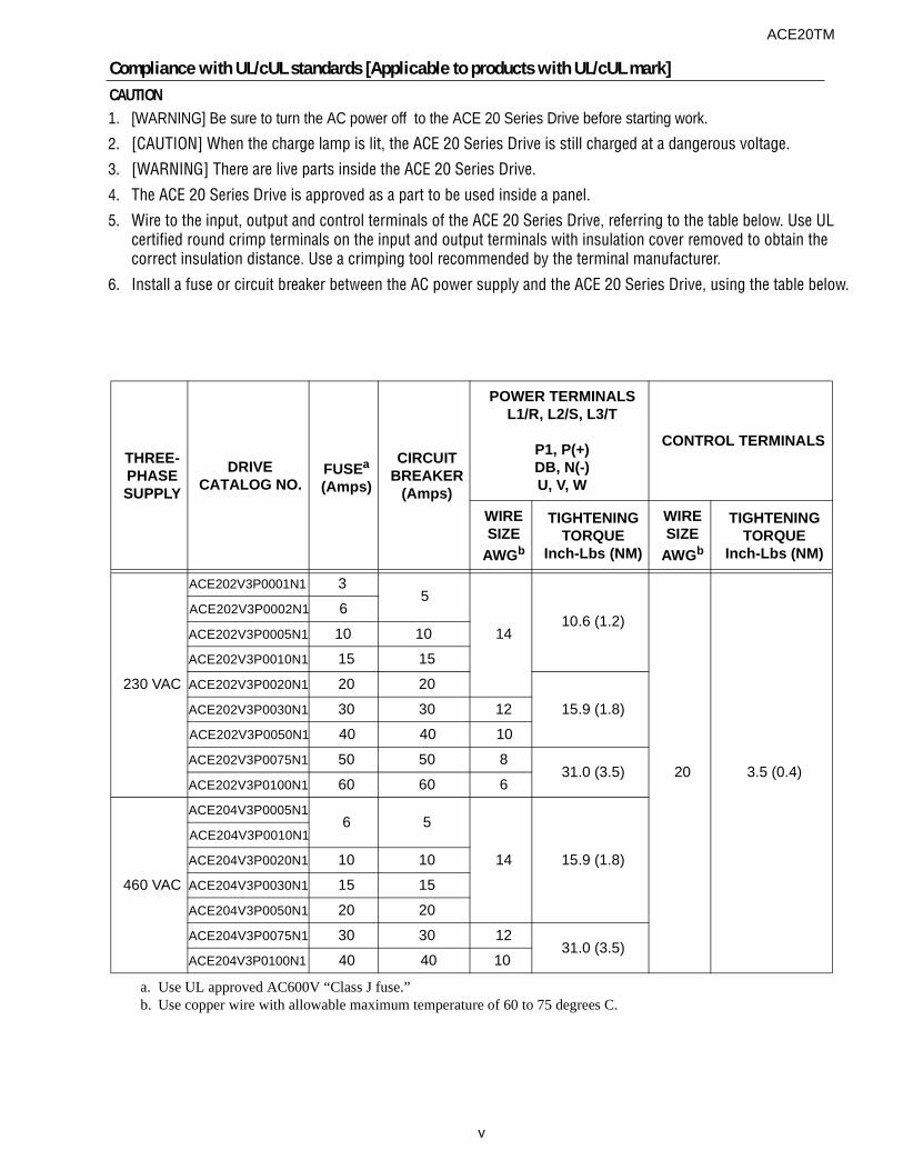
5. Wire to the input, output and control terminals of the ACE 20 Series Drive, referring to the table below. Use UL certified round crimp terminals on the input and output terminals with insulation cover removed to obtain the correct insulation distance. Use a crimping tool recommended by the terminal manufacturer.
6. Install a fuse or circuit breaker between the AC power supply and the ACE 20 Series Drive, using the table below.
Compliance with UL/cUL standards [Applicable to products with UL/cUL mark]CAUTION
v
ACE20TM
THREE-PHASESUPPLY
DRIVECATALOG NO.
FUSEa
(Amps)
a. Use UL approved AC600V “Class J fuse.”
CIRCUITBREAKER
(Amps)
POWER TERMINALSL1/R, L2/S, L3/T
P1, P(+)DB, N(-)U, V, W
CONTROL TERMINALS
WIRESIZE
AWGb
b. Use copper wire with allowable maximum temperature of 60 to 75 degrees C.
TIGHTENINGTORQUE
Inch-Lbs (NM)
WIRESIZE
AWGb
TIGHTENINGTORQUE
Inch-Lbs (NM)
230 VAC
ACE202V3P0001N1 35
1410.6 (1.2)
20 3.5 (0.4)
ACE202V3P0002N1 6
ACE202V3P0005N1 10 10ACE202V3P0010N1 15 15
ACE202V3P0020N1 20 20
15.9 (1.8)ACE202V3P0030N1 30 30 12ACE202V3P0050N1 40 40 10
ACE202V3P0075N1 50 50 831.0 (3.5)
ACE202V3P0100N1 60 60 6
460 VAC
ACE204V3P0005N16 5
14 15.9 (1.8)
ACE204V3P0010N1
ACE204V3P0020N1 10 10ACE204V3P0030N1 15 15
ACE204V3P0050N1 20 20
ACE204V3P0075N1 30 30 1231.0 (3.5)
ACE204V3P0100N1 40 40 10

CAUTION7. ACE 20 Series, 230V drives, are suitable for use on a circuit capable of delivering not more than 20,000 rms
symmetrical amperes, 240V maximum.
8. ACE 20 Series, 460V drives, are suitable for use on a circuit capable of delivering not more than the followingsymmetrical amperes, 480V maximum: When a fuse is installed, 20,000A; when the circuit breaker is installed,5000A.
9. ACE 20 Series Drives are supplied as standard with a NEMA 1 enclosure.
10. A class 2 circuit wired with class 1 wire.
vi
ACE20TM
ACE20TM
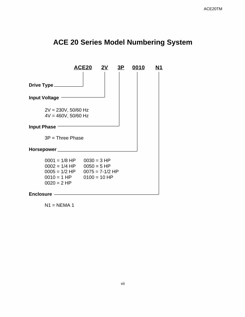
ACE 20 Series Model Numbering System
ACE20 2V 3P 0010 N1
Drive Type
Input Voltage
2V = 230V, 50/60 Hz 4V = 460V, 50/60 Hz
Input Phase
3P = Three Phase
Horsepower
0001 = 1/8 HP 0030 = 3 HP 0002 = 1/4 HP 0050 = 5 HP 0005 = 1/2 HP 0075 = 7-1/2 HP 0010 = 1 HP 0100 = 10 HP 0020 = 2 HP
Enclosure
N1 = NEMA 1
vii
HP Rating EnclosureOutput Current
(A)Overload (A) (150% 1min.) Catalog No. Item Code
Dimensions H* x W x D (inches)
Weight (lbs)
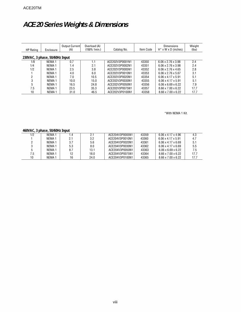
230VAC, 3 phase, 50/60Hz Input 1/8 NEMA 1 0.7 1.1 ACE202V3P0001N1 43350 6.06 x 2.76 x 3.98 2.41/4 NEMA 1 1.4 2.1 ACE202V3P0002N1 43351 6.06 x 2.76 x 3.98 2.41/2 NEMA 1 2.5 3.8 ACE202V3P0005N1 43352 6.06 x 2.76 x 4.65 2.81 NEMA 1 4.0 6.0 ACE202V3P0010N1 43353 6.06 x 2.76 x 5.67 3.12 NEMA 1 7.0 10.5 ACE202V3P0020N1 43354 6.06 x 4.17 x 5.91 5.13 NEMA 1 10.0 15.0 ACE202V3P0030N1 43355 6.06 x 4.17 x 5.91 5.15 NEMA 1 16.5 24.8 ACE202V3P0050N1 43356 6.06 x 6.69 x 6.22 7.9
7.5 NEMA 1 23.5 35.3 ACE202V3P0075N1 43357 8.66 x 7.00 x 6.22 17.710 NEMA 1 31.0 46.5 ACE202V3P0100N1 43358 8.66 x 7.00 x 6.22 17.7
460VAC, 3 phase, 50/60Hz Input 1/2 NEMA 1 1.4 2.1 ACE204V3P0005N1 43359 6.06 x 4.17 x 4.96 4.31 NEMA 1 2.1 3.2 ACE204V3P0010N1 43360 6.06 x 4.17 x 5.91 4.72 NEMA 1 3.7 5.6 ACE204V3P0020N1 43361 6.06 x 4.17 x 6.69 5.13 NEMA 1 5.3 8.0 ACE204V3P0030N1 43362 6.06 x 4.17 x 6.69 5.55 NEMA 1 8.7 13.1 ACE204V3P0050N1 43363 6.06 x 6.69 x 6.22 7.5
7.5 NEMA 1 12 18.0 ACE204V3P0075N1 43364 8.66 x 7.00 x 6.22 17.710 NEMA 1 16 24.0 ACE204V3P0100N1 43365 8.66 x 7.00 x 6.22 17.7
ACE 20 Series Weights & Dimensions
viii
ACE20TM
*With NEMA 1 Kit.
1-1
1. Before Using ACE 20 Series Drives1.1 Receiving InspectionIf you have any problems with the drive, contact thedistributor or Boston Gear.
Unpack and check the following items.
(1) Check the ratings nameplate to confirm that thedrive is the one that was ordered.
SOURCE: Number of input phases, input voltage,input frequency, input current
OUTPUT: Number of output phases, rated outputcapacity, rated output voltage, outputfrequency range, rated output current,overload current rating
(2) Check for breakage, missing parts, and dents orother damage on the cover and the main bodythat may have occurred during transportation.
(3) Instruction manual for the drive is included.
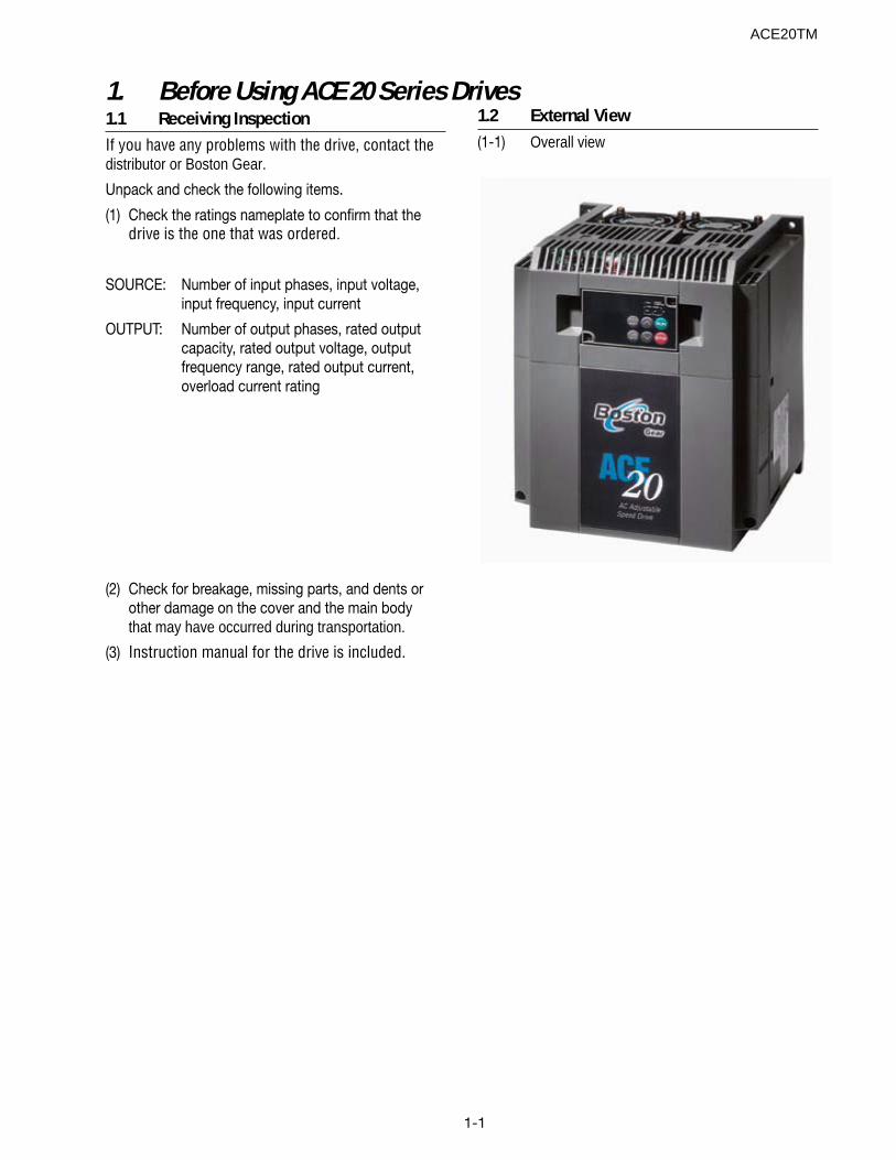
1.2 External View(1-1) Overall view
ACE20TM
1-2
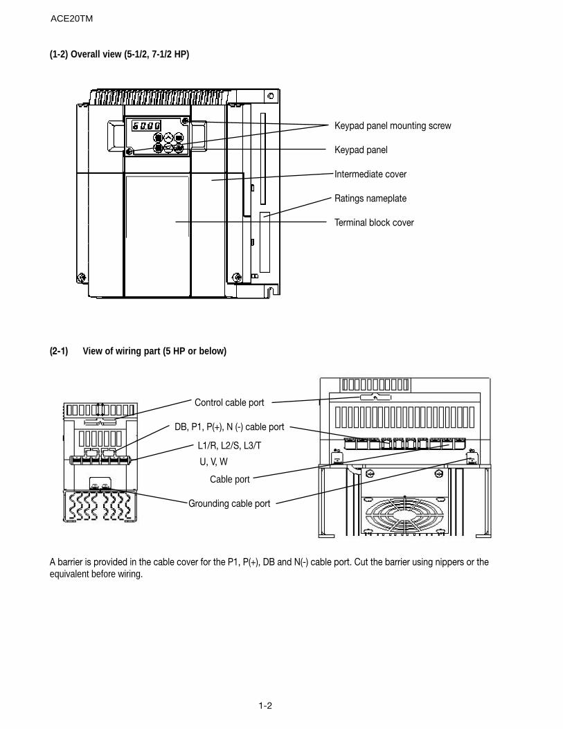
(2-1) View of wiring part (5 HP or below)
Keypad panel mounting screw
Keypad panel
Intermediate cover
Ratings nameplate
Terminal block cover
Control cable port
DB, P1, P(+), N (-) cable port
L1/R, L2/S, L3/T
U, V, W
Cable port
Grounding cable port
A barrier is provided in the cable cover for the P1, P(+), DB and N(-) cable port. Cut the barrier using nippers or theequivalent before wiring.
(1-2) Overall view (5-1/2, 7-1/2 HP)
ACE20TM

1-3
(2-2) View of wiring part (7-1/2, 10 HP)
Terminal block cover
Control cable port
L1/R, L2/S, L3/T cable port
P1, P(+), DB, N(-) cable port
U, V, W cable port
Cable cover
Grounding cable port
Fig. 1-3-1 Removing the control terminal block cover
A barrier is provided in the cable cover for the P1, P(+), DB and N(-) cable port. Cut the barrier using nippers or theequivalent before wiring.
1.3 Handling(1) Removing the control terminal block cover (5 HP or below)
While lightly pushing in the sides of the control terminal block cover at the catches, lift the cover asshown in Fig. 1-3-1.
ACE20TM
1-4
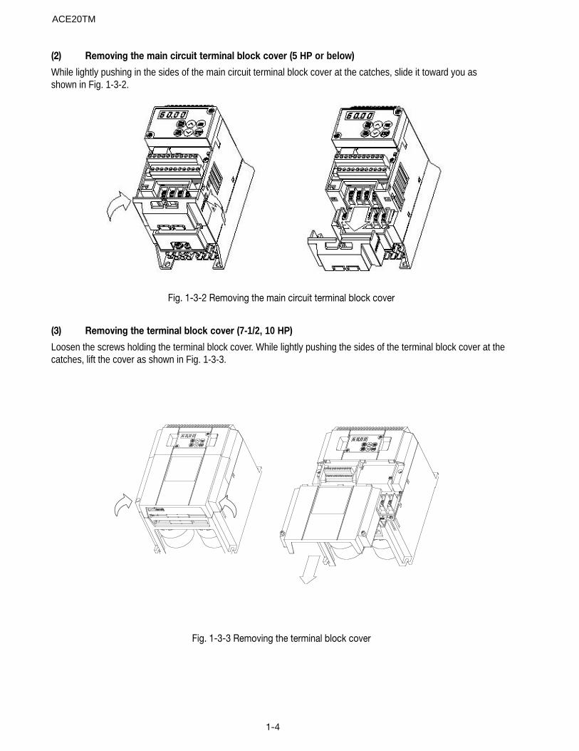
(2) Removing the main circuit terminal block cover (5 HP or below)
While lightly pushing in the sides of the main circuit terminal block cover at the catches, slide it toward you asshown in Fig. 1-3-2.
Fig. 1-3-2 Removing the main circuit terminal block cover
(3) Removing the terminal block cover (7-1/2, 10 HP)
Loosen the screws holding the terminal block cover. While lightly pushing the sides of the terminal block cover at thecatches, lift the cover as shown in Fig. 1-3-3.
Fig. 1-3-3 Removing the terminal block cover
ACE20TM
1-5
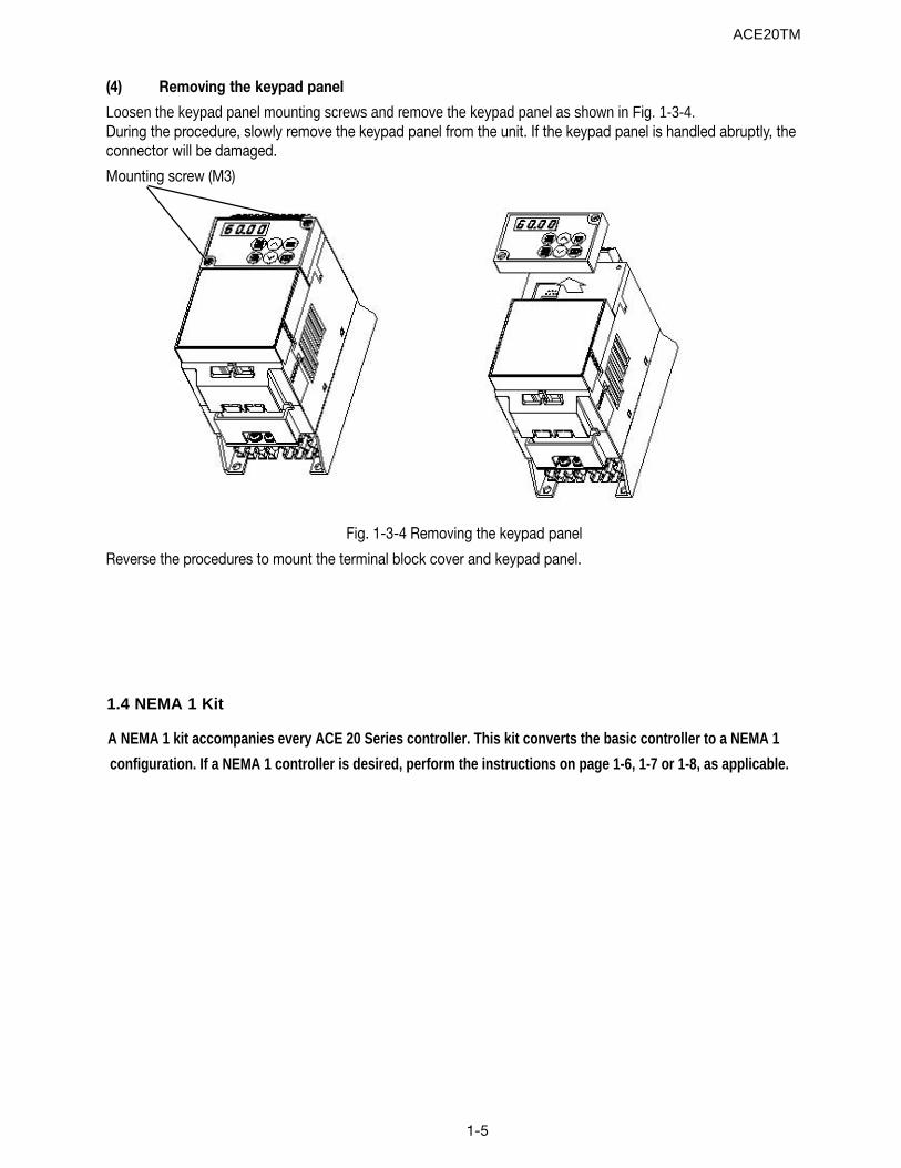
(4) Removing the keypad panel
Loosen the keypad panel mounting screws and remove the keypad panel as shown in Fig. 1-3-4.During the procedure, slowly remove the keypad panel from the unit. If the keypad panel is handled abruptly, theconnector will be damaged.
Mounting screw (M3)
Fig. 1-3-4 Removing the keypad panel
Reverse the procedures to mount the terminal block cover and keypad panel.
ACE20TM
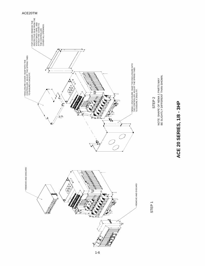
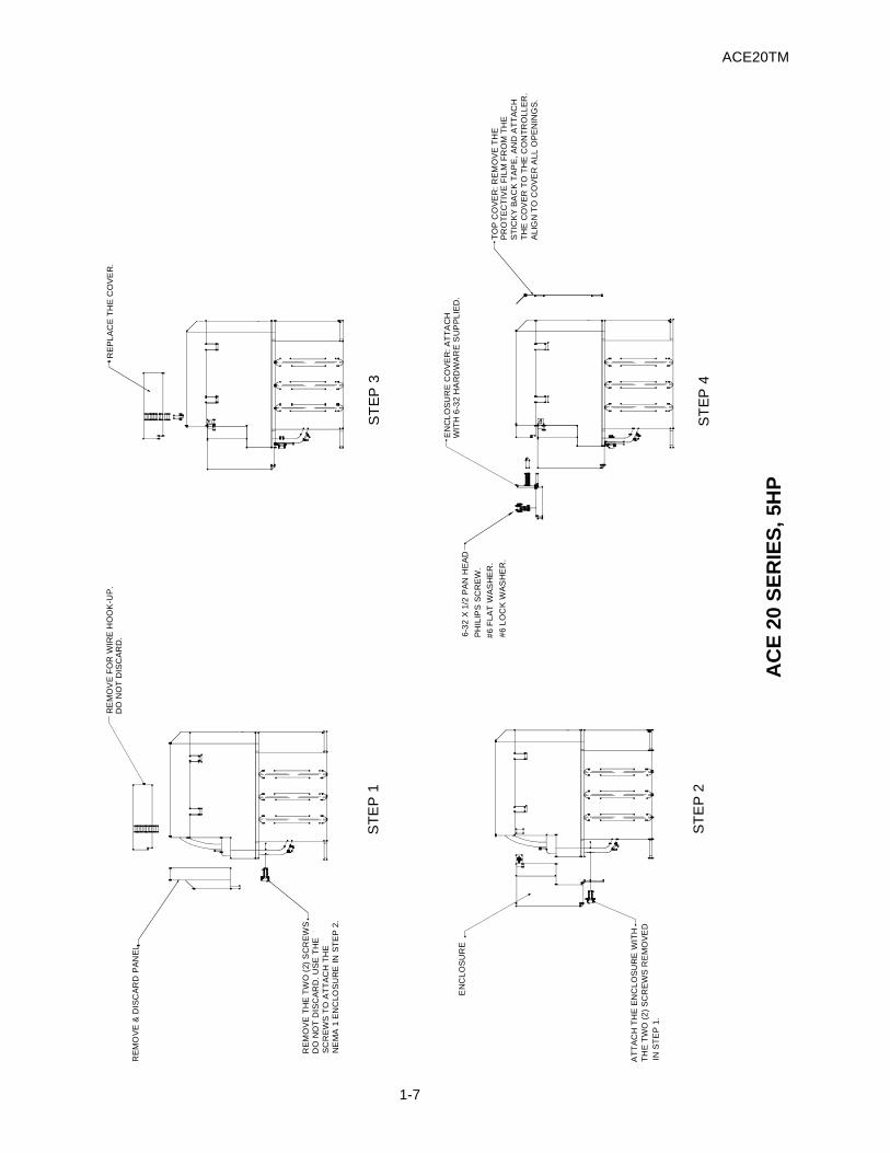
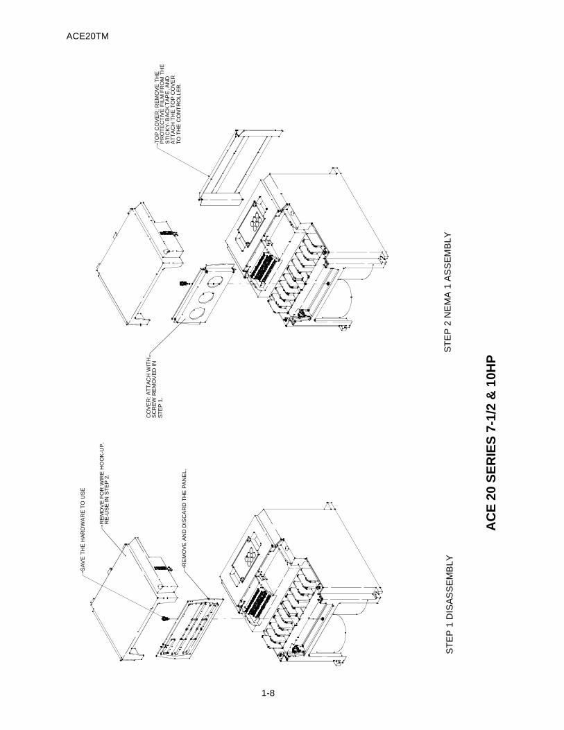
A NEMA 1 kit accompanies every ACE 20 Series controller. This kit converts the basic controller to a NEMA 1
configuration. If a NEMA 1 controller is desired, perform the instructions on page 1-6, 1-7 or 1-8, as applicable.
1.4 NEMA 1 Kit
ACE20TM
1-6
RE
MO
VE
AN
D D
ISC
AR
D
RE
MO
VE
AN
D D
ISC
AR
D
ST
EP
1
TO
P C
OV
ER
: R
EM
OV
E T
HE
NE
MA
1 E
NC
LOS
UR
E:
SN
AP
TH
E E
NC
LOS
UR
E IN
TO
TH
E C
ON
TR
OLL
ER
. AD
JUS
T T
HE
SP
RIN
G T
AB
ST
O E
NS
UR
E A
SN
UG
FIT
.
CO
NT
RO
LLE
R. A
DJU
ST
TH
E S
PR
ING
TA
BS
EN
CL
OS
UR
E C
OV
ER
: SN
AP
INT
O T
HE
TO
EN
SU
RE
A S
NU
G F
IT.
ST
EP
2N
OT
E:
SH
AP
E O
F N
EM
A 1
PA
RT
S M
AY
BE
SLI
GH
TL
Y D
IFF
ER
EN
T T
HA
N S
HO
WN
.
AT
TA
CH
TH
E C
OV
ER
TO
PR
OT
EC
TIV
E F
ILM
FR
OM
TH
ES
TIC
KY
BA
CK
TA
PE
, A
ND
CO
VE
R A
LL
OP
EN
ING
S.
TH
E C
ON
TR
OL
LER
.
AC
E 2
0 S
ER
IES
, 1 /8
- 3
HP
ACE20TM
1-7
AC
E 2
0 S
ER
IES
, 5H
P
RE
MO
VE
& D
ISC
AR
D P
AN
EL
RE
MO
VE
FO
R W
IRE
HO
OK
-UP
.D
O N
OT
DIS
CA
RD
.
RE
MO
VE
TH
E T
WO
(2)
SC
RE
WS
DO
NO
T D
ISC
AR
D. U
SE
TH
E
SC
RE
WS
TO
AT
TA
CH
TH
EN
EM
A 1
EN
CLO
SU
RE
IN S
TE
P 2
.
ST
EP
1
E
NC
LO
SU
RE
AT
TA
CH
TH
E E
NC
LO
SU
RE
WIT
HT
HE
TW
O (
2)
SC
RE
WS
RE
MO
VE
DIN
ST
EP
1.
ST
EP
2
RE
PL
AC
E T
HE
CO
VE
R.
ST
EP
3
EN
CL
OS
UR
E C
OV
ER
: A
TT
AC
HW
ITH
6-3
2 H
AR
DW
AR
E S
UP
PL
IED
.
TO
P C
OV
ER
: R
EM
OV
E T
HE
PR
OT
EC
TIV
E F
ILM
FR
OM
TH
E
ST
ICK
Y B
AC
K T
AP
E,
AN
D A
TT
AC
H
TH
E C
OV
ER
TO
TH
E C
ON
TR
OLL
ER
. A
LIG
N T
O C
OV
ER
ALL
OP
EN
ING
S.
ST
EP
4
#6
FL
AT
WA
SH
ER
.
#6
LO
CK
WA
SH
ER
.
6-3
2 X
1/2
PA
N H
EA
D
PH
ILIP
S S
CR
EW
.
ACE20TM
1-8
AC
E 2
0 S
ER
IES
7-1
/2 &
1 0H
P
RE
MO
VE
AN
D D
ISC
AR
D T
HE
PA
NE
L.
SA
VE
TH
E H
AR
DW
AR
E T
O U
SE
ST
EP
1 D
ISA
SS
EM
BLY
RE
MO
VE
FO
R W
IRE
HO
OK
-UP
.R
E-U
SE
IN S
TE
P 2
.
TO
P C
OV
ER
: RE
MO
VE
TH
E
PR
OT
EC
TIV
E F
ILM
FR
OM
TH
E
CO
VE
R: A
TT
AC
H W
ITH
SC
RE
W R
EM
OV
ED
IN
ST
EP
2 N
EM
A 1
AS
SE
MB
LY
ST
EP
1.
TO
TH
E C
ON
TR
OLL
ER
.A
TT
AC
H T
HE
TO
P C
OV
ER
TA
PE
, AN
DB
AC
KS
TIC
KY
-
1-9
Item Specifications
Ambient temperature -10 to +40°C (+14 to +104°F)
Storage temperature1 -25 to +65°C (-4 to +149°F)
Relative humidity 5 to 95%2
Atmosphere
86 to 106kPa (During storage)
70 to 106kPa (During transportation)
Places not subjected to abrupt temperature changes or condensation or freezing
The drive must not be exposed to dust, direct sunlight, corrosive or flammable gases, oil mist, vapor, water drops or vibration. There must be little salt in the atmosphere.
Atmospheric pressure
Table 1-5-1 Storage environment
Note 1: The storage temperature is for a short time, such as for transportation, etc.
Note 2: Even if the humidity is within the requirements of the specifications, places with abrupt temperaturechanges are subject to condensation or freezing. AAvoid storing the drive in such places.
(1) Do not place the drive directly on the floor.
(2) If the ambient atmosphere is adverse, wrap the drive in a vinyl sheet or similar protection when storing.
(3) If humidity may be present, add a drying agent (such as silica gel) in the package prepared as describedin item (2).
To store for long periods.
The long term storage method of the drive varies largely according to the environment of the storage site. GGeneralstorage methods are described below.
(1) The storage site must satisfy the requirements of specifications for temporary storage.
However, for storage exceeding three months, the upper limit of the ambient temperature shall not exceed30°C (86°F). This is to prevent deterioration of unpowered electrolytic capacitors.
(2) The package must be air tight so that moisture will not enter. Add a drying agent inside the package to maintaina relative humidity inside the package of 70%.
(3) A drive installed in an enclosure or control panel and stored is likely to be exposed to moisture and dust. If this is thecase, remove the drive and move it to a preferable environment, as in item (1) or (2).
(4) Electrolytic capacitors left unpowered for an extended period of time may deteriorate. Do not store for more than oneyear without applying power to the drive.
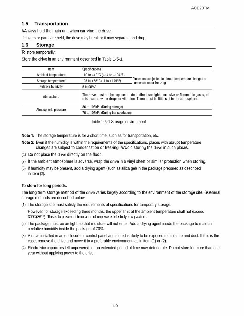
1.5 TransportationAAlways hold the main unit when carrying the drive.
If covers or parts are held, the drive may break or it may separate and drop.
1.6 StorageTo store temporarily:
Store the drive in an environment described in Table 1-5-1.
ACE20TM
ACE20TM
1-10
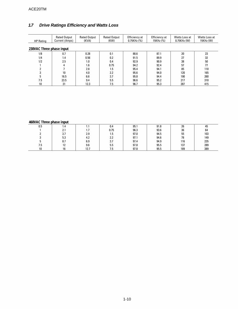
1.7 Drive Ratings Efficiency and Watts Loss
HP RatingRated Output
Current (Amps)Rated Output
(KVA)Rated Output
(KW)Efficiency at 0.75KHz (%)
Efficiency at 15KHz (%)
Watts Loss at 0.75KHz (W)
Watts Loss at 15KHz (W)
230VAC Three phase input1/8 0.7 0.28 0.1 88.6 87.1 20 231/4 1.4 0.56 0.2 91.5 89.9 27 321/2 2.5 1.0 0.4 92.9 90.9 38 501 4 1.6 0.75 94.2 92.4 57 772 7 2.8 1.5 95.4 94.1 85 1103 10 4.0 2.2 95.6 94.0 120 1655 16.5 6.6 3.7 95.8 94.4 190 260
7.5 23.5 9.4 5.5 96.6 95.2 217 31010 31 12.3 7.5 96.7 95.3 287 415
460VAC Three phase input0.5 1.4 1.1 0.4 95.1 91.8 26 451 2.1 1.7 0.75 96.3 93.6 36 642 3.7 2.9 1.5 97.0 94.5 55 1033 5.3 4.2 2.2 97.1 94.6 78 1495 8.7 6.9 3.7 97.4 94.9 116 235
7.5 12 9.6 5.5 97.8 95.5 137 28910 16 12.7 7.5 97.8 95.5 189 389
2-1
2. Installation and Connections
Item SpecificationsSite Indoors
Ambient Temperature -10 to +40°C (+14 to 104°F)
Relative Humidity 5 to 95% (without condensation)
Atmosphere
The drive must not be exposed to dust, direct sunlight, corrosive gases, oil mist, vapor or water drops. There must be little salt. No condensation shall occur due to abrupt temperature changes.
Altitude 3,300 ft. (1,000m) max. [Refer to Table 2-1-2 for altitudes exceeding 3,300 ft. (1000m.)]
Atmospheric Pressure 86 to 106 kPa
Vibration 3mm 2 to 9 Hz9.8m/s2 9 to 20 Hz2m/s2 20 to 55 Hz1m/s2 55 to 200 Hz
2.1 Operating EnvironmentInstall the drive in an environment as described in Table2-1-1.
Table 2-1-1 Operating environment
Table 2-1-2 Output attenuation ratio in relation toaltitude
2.2 Installation Method(1) Securely mount the drive in the upright position on
a rigid structure so that the drive keypadfaces front. Avoid mounting the drive upsidedown or horizontally.
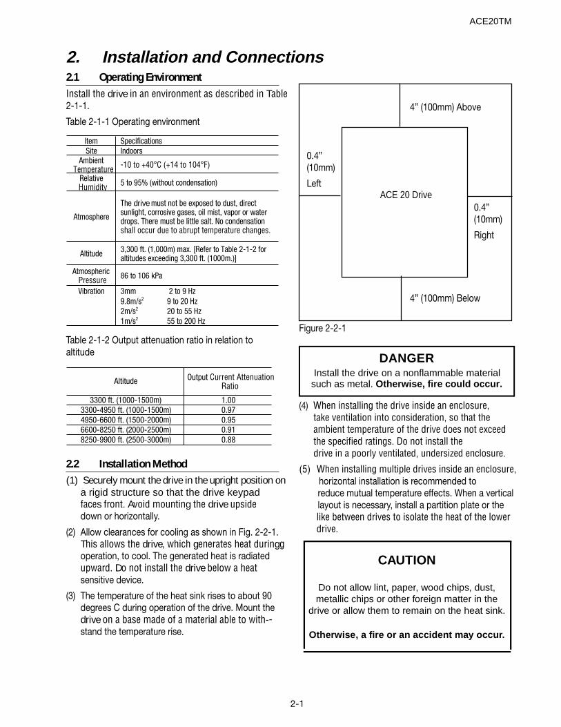
(2) Allow clearances for cooling as shown in Fig. 2-2-1.This allows the drive, which generates heat duringgoperation, to cool. The generated heat is radiatedupward. Do not install the drive below a heatsensitive device.
(3) The temperature of the heat sink rises to about 90degrees C during operation of the drive. Mount thedrive on a base made of a material able to with--stand the temperature rise.
Figure 2-2-1
ACE 20 Drive
4” (100mm) Above
0.4”(10mm)
Right
0.4”(10mm)
Left
4” (100mm) Below
ACE20TM
CAUTION
Do not allow lint, paper, wood chips, dust,metallic chips or other foreign matter in the
drive or allow them to remain on the heat sink.
Otherwise, a fire or an accident may occur.
Altitude Output Current Attenuation Ratio
3300 ft. (1000-1500m) 1.003300-4950 ft. (1000-1500m) 0.974950-6600 ft. (1500-2000m) 0.956600-8250 ft. (2000-2500m) 0.918250-9900 ft. (2500-3000m) 0.88
(4) When installing the drive inside an enclosure,take ventilation into consideration, so that theambient temperature of the drive does not exceedthe specified ratings. Do not install thedrive in a poorly ventilated, undersized enclosure.
(5) When installing multiple drives inside an enclosure, horizontal installation is recommended toreduce mutual temperature effects. When a verticallayout is necessary, install a partition plate or thelike between drives to isolate the heat of the lowerdrive.
DANGERInstall the drive on a nonflammable material
such as metal. Otherwise, fire could occur.
2-2
2.3 ConnectionsRemove the control terminal block cover to connect tothe control terminal block. Remove the main circuitterminal block cover to connect to the main circuitterminal block. Connect cables using the followingprecautions.
2-3-1 Basic Connections
(1) Be sure to connect the power cables to the main circuitpower terminals L1/R, L2/S and L3/T of the drive. Ifthe power cables are connected to other terminals,the drive will be damaged. Be sure the line voltageis within the allowable voltage range specified onthe drive nameplate.
(2) Connect the grounding terminal according tonational and local electric codes to prevent electricshock, fire or other disasters, and to reduce electricnoise. Ground must be connected.
(3) Use reliable crimp terminals for connection ofcables to the terminals.
(4) After wiring, check the following:
a. Check that the cables are connected to thecorrect termianls.
b. Check that there are no bad crimps orconnections.
c. Check that terminals or cables are not shortcircuited and there is no ground fault.
(5) To change connection of a drive that has beenturned on, observe the following:
The smoothing capacitor in the direct current part ofthe main circuit takes time to discharge after it isturned off. To avoid danger, check the DC voltage(across main circuit terminals P(+) and N(-)) for a safevoltage (25 VDC or lower) using a multi-meter, after thecharge lamp is off. Wait until the residual voltage isdischarged before shorting a circuit, to avoid being hitby sparks caused by the voltage (electric charge).
DANGER• Be sure to connect the grounding cable.
Otherwise, electric shock or fire couldoccur.
• Only qualified electricians should wire the drive.
Otherwise, electric shock could occur.
• Perform wiring after checking that the powersupply is turned off.
Otherwise, electric shock could occur.
ACE20TM
2-3
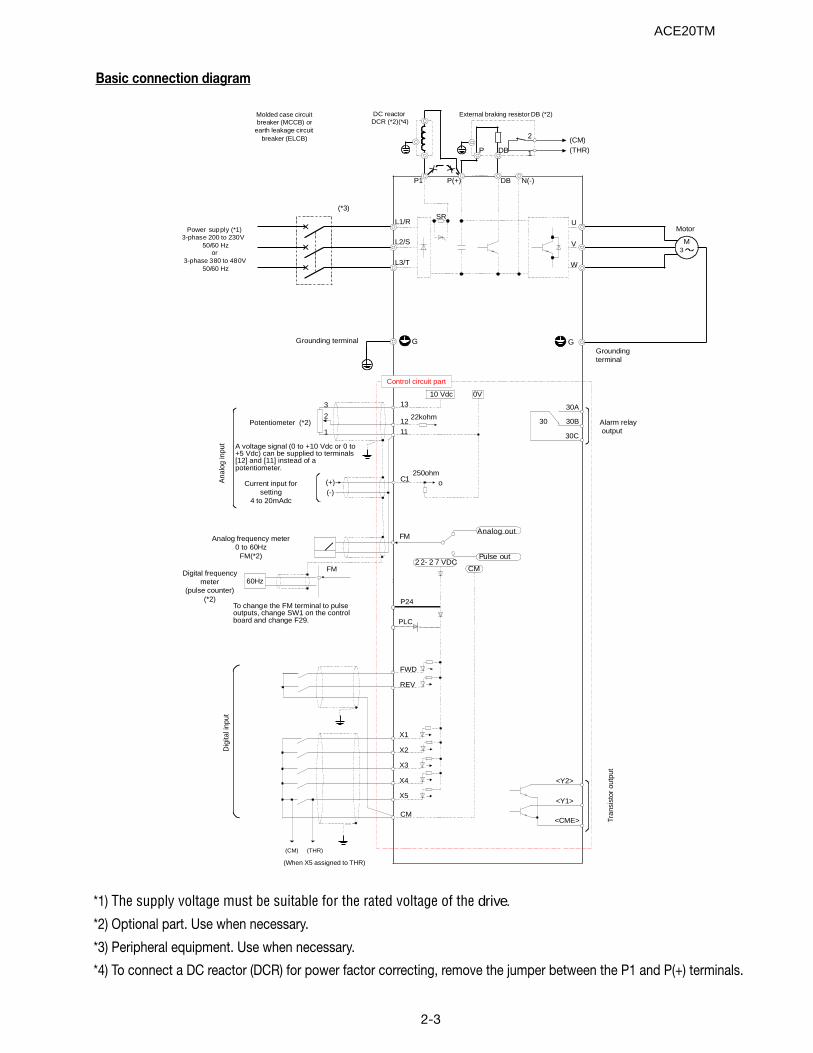
Basic connection diagram
*1) The supply voltage must be suitable for the rated voltage of the drive.
*2) Optional part. Use when necessary.
*3) Peripheral equipment. Use when necessary.
*4) To connect a DC reactor (DCR) for power factor correcting, remove the jumper between the P1 and P(+) terminals.
FWD
REV
X1
X2
X3
X4
X5
CM
13
12
11
C1
FM
L1/R U
V
W
P1 P(+) DB N(-)
M
<Y2>
<Y1>
<CME>
G
Motor
Groundingterminal
SR
10 Vdc
(-)(+)
0V
2 2- 2 7 VDCCM
Pulse out
Control circuit part
Analog frequency meter0 to 60Hz
FM(*2)
Current input forsetting
4 to 20mAdc
A voltage signal (0 to +10 Vdc or 0 to+5 Vdc) can be supplied to terminals[12] and [11] instead of apotentiometer.
Potentiometer (*2)
DC reactor DCR (*2)(*4)
External braking resistor DB (*2)
P DB
2
1
L2/S
L3/T
Tran
sist
or o
utpu
t
Dig
ital i
nput
Ana
log
inpu
t
Alarm relay output
30
30A
30B
30C
3
2
1
GGrounding terminal
(CM)(THR)
Power supply (*1)3-phase 200 to 230V
50/60 Hzor
3-phase 380 to 480V 50/60 Hz
Molded case circuitbreaker (MCCB) or
earth leakage circuitbreaker (ELCB)
(*3)
Digital frequencymeter
(pulse counter)(*2)
60Hz
22kohm
FM
Analog out
o250ohm
To change the FM terminal to pulseoutputs, change SW1 on the controlboard and change F29.
(CM) (THR)
(When X5 assigned to THR)
3
PLC
P24
ACE20TM
2-4
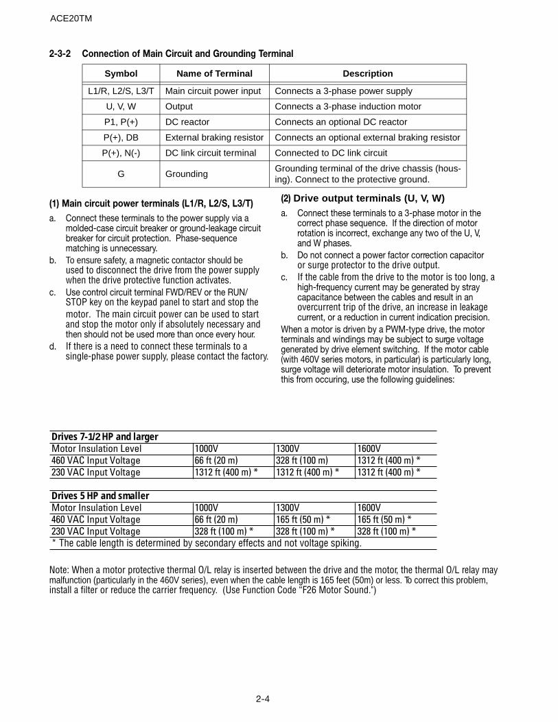
2-3-2 Connection of Main Circuit and Grounding Terminal
Drives 7-1/2 HP and largerMotor Insulation Level 1000V 1300V 1600V460 VAC Input Voltage 66 ft (20 m) 328 ft (100 m) 1312 ft (400 m) *230 VAC Input Voltage 1312 ft (400 m) * 1312 ft (400 m) * 1312 ft (400 m) *
Drives 5 HP and smallerMotor Insulation Level 1000V 1300V 1600V460 VAC Input Voltage 66 ft (20 m) 165 ft (50 m) * 165 ft (50 m) *230 VAC Input Voltage 328 ft (100 m) * 328 ft (100 m) * 328 ft (100 m) ** The cable length is determined by secondary effects and not voltage spiking.
Note: When a motor protective thermal O/L relay is inserted between the drive and the motor, the thermal O/L relay maymalfunction (particularly in the 460V series), even when the cable length is 165 feet (50m) or less. To correct this problem,install a filter or reduce the carrier frequency. (Use Function Code “F26 Motor Sound.")
(1) Main circuit power terminals (L1/R, L2/S, L3/T)a. Connect these terminals to the power supply via a
molded-case circuit breaker or ground-leakage circuitbreaker for circuit protection. Phase-sequencematching is unnecessary.
b. To ensure safety, a magnetic contactor should beused to disconnect the drive from the power supplywhen the drive protective function activates.
c. Use control circuit terminal FWD/REV or the RUN/STOP key on the keypad panel to start and stop themotor. The main circuit power can be used to startand stop the motor only if absolutely necessary andthen should not be used more than once every hour.
d. If there is a need to connect these terminals to asingle-phase power supply, please contact the factory.
(2) Drive output terminals (U, V, W)a. Connect these terminals to a 3-phase motor in the
correct phase sequence. If the direction of motorrotation is incorrect, exchange any two of the U, V,and W phases.
b. Do not connect a power factor correction capacitoror surge protector to the drive output.
c. If the cable from the drive to the motor is too long, ahigh-frequency current may be generated by straycapacitance between the cables and result in anovercurrent trip of the drive, an increase in leakagecurrent, or a reduction in current indication precision.
When a motor is driven by a PWM-type drive, the motorterminals and windings may be subject to surge voltagegenerated by drive element switching. If the motor cable(with 460V series motors, in particular) is particularly long,surge voltage will deteriorate motor insulation. To preventthis from occuring, use the following guidelines:
ACE20TM
Symbol Name of Terminal Description
L1/R, L2/S, L3/T Main circuit power input Connects a 3-phase power supply
U, V, W Output Connects a 3-phase induction motor
P1, P(+) DC reactor Connects an optional DC reactor
P(+), DB External braking resistor Connects an optional external braking resistor
P(+), N(-) DC link circuit terminal Connected to DC link circuit
G GroundingGrounding terminal of the drive chassis (hous-ing). Connect to the protective ground.
2-5
(3) DC reactor connecting terminals (P1, P(+))
a. Use these terminals to connect a DC reactor (option).Remove the jumper connected at the factory beforeconnecting the DC reactor.
b. Do not remove the jumper if no DC reactor is used.
Cut the barrier in the main circuit terminal block coverfor the P1, P(+), DB and N(-) cable port using nippersor the equivalent when connecting wiring.
CAUTIONA DC reactor does not come with the drive. Use a DC reactor or AC reactor under theconditions listed below.
1. When the capacity of the power supply trans-former exceeds 500 kVA and exceeds10 times therated capacity of the drive.
2. When a thyristor converter is a common load onthe same transformer. If the communicating reactor isnot used for the thyristor converter, an AC reactor isnecessary at the drive input side.
3. Used to prevent a OV trip from occuring whenthe phase advance capacitor in the power line isswitched on and off.
4. When the voltage imbalance exceeds 3%
Imbalance rate between phases [%] =
(Max. voltage [V] - Min voltage [V])
3-phase average voltage [V]
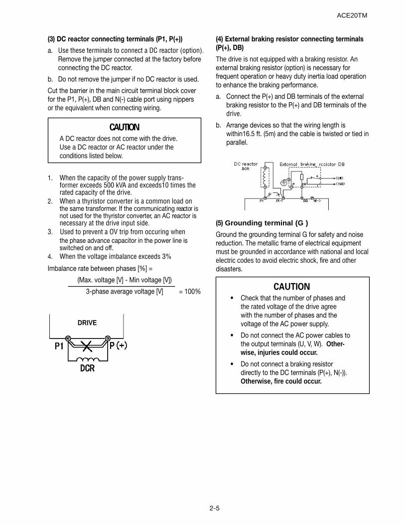
(4) External braking resistor connecting terminals(P(+), DB)
The drive is not equipped with a braking resistor. Anexternal braking resistor (option) is necessary forfrequent operation or heavy duty inertia load operationto enhance the braking performance.
a. Connect the P(+) and DB terminals of the externalbraking resistor to the P(+) and DB terminals of thedrive.
b. Arrange devices so that the wiring length iswithin16.5 ft. (5m) and the cable is twisted or tied inparallel.
(5) Grounding terminal (G )
Ground the grounding terminal G for safety and noisereduction. The metallic frame of electrical equipmentmust be grounded in accordance with national and localelectric codes to avoid electric shock, fire and otherdisasters.
DRIVE
= 100% CAUTION• Check that the number of phases and
the rated voltage of the drive agreewith the number of phases and thevoltage of the AC power supply.
• Do not connect the AC power cables tothe output terminals (U, V, W). Other-wise, injuries could occur.
• Do not connect a braking resistordirectly to the DC terminals (P(+), N(-)).Otherwise, fire could occur.
ACE20TM
2-6
Clas
sific
atio
n
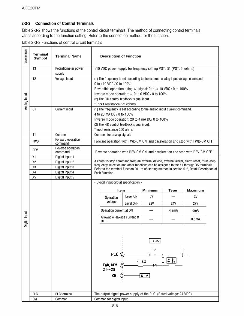
Terminal Symbol Terminal Name Description of Function
13 Potentiometer power +10 VDC power supply for frequency setting POT. G1 (POT: 5 kohms)supply
12 Voltage input (1) The frequency is set according to the external analog input voltage command.0 to +10 VDC / 0 to 100%Reversible operation using +/- signal: 0 to +/-10 VDC / 0 to 100%Inverse mode operation: +10 to 0 VDC / 0 to 100%(2) The PID control feedback signal input.* Input resistance: 22 kohms
C1 Current input (1) The frequency is set according to the analog input current command.4 to 20 mA DC / 0 to 100%Inverse mode operation: 20 to 4 mA DC/ 0 to 100%(2) The PID control feedback signal input.* Input resistance 250 ohms
11 Common Common for analog signals
FWD Forward operation command Forward operation with FWD-CM ON, and deceleration and stop with FWD-CM OFF
REV Reverse operation command Reverse operation with REV-CM ON, and deceleration and stop with REV-CM OFF
X1 Digital input 1X2 Digital input 2X3 Digital input 3X4 Digital input 4X5 Digital input 5
<Digital input circuit specification>
PLC PLC terminal The output signal power supply of the PLC. (Rated voltage: 24 VDC)CM Common Common for digital input
A coast-to-stop command from an external device, external alarm, alarm reset, multi-step frequency selection and other functions can be assigned to the X1 through X5 terminals. Refer to the terminal function E01 to 05 setting method in section 5-2, Detail Description of Each Function.
Anal
og In
put
Digi
tal I
nput
2-3-3 Connection of Control Terminals
Table 2-3-2 shows the functions of the control circuit terminals. The method of connecting control terminalsvaries according to the function setting. Refer to the connection method for the function.
Table 2-3-2 Functions of control circuit terminals
Minimum Type Maximum
Level ON 0V — 2V
Level OFF 22V 24V 27V
— 4.2mA 6mA
— — 0.5mA
Operation voltage
Operation current at ON
Allowable leakage current at OFF
Item
ACE20TM
2-7
Clas
sific
atio
n
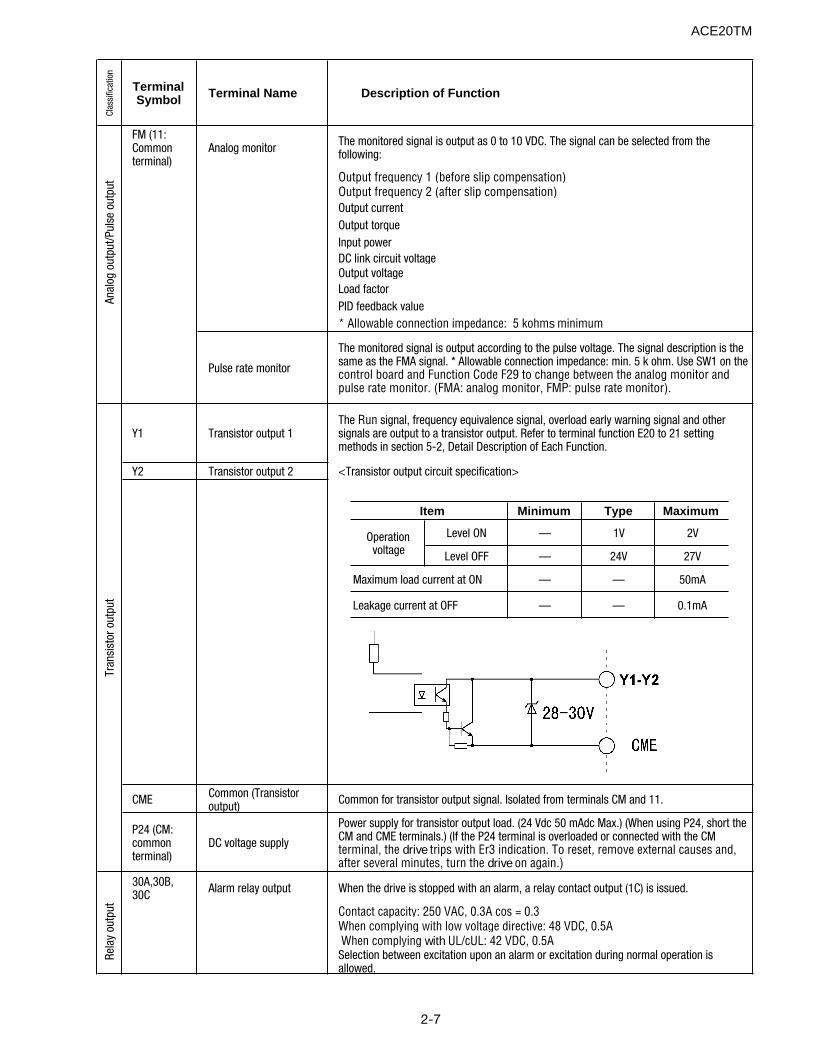
Terminal Symbol Terminal Name Description of Function
FM (11: Common terminal)
Analog monitor The monitored signal is output as 0 to 10 VDC. The signal can be selected from the following:
Output frequency 1 (before slip compensation)Output frequency 2 (after slip compensation)Output currentOutput torqueInput powerDC link circuit voltageOutput voltageLoad factorPID feedback value* Allowable connection impedance: 5 kohms minimum
Pulse rate monitor
The monitored signal is output according to the pulse voltage. The signal description is the same as the FMA signal. * Allowable connection impedance: min. 5 k ohm. Use SW1 on the control board and Function Code F29 to change between the analog monitor and pulse rate monitor. (FMA: analog monitor, FMP: pulse rate monitor).
Y1 Transistor output 1The Run signal, frequency equivalence signal, overload early warning signal and other signals are output to a transistor output. Refer to terminal function E20 to 21 setting methods in section 5-2, Detail Description of Each Function.
Y2 Transistor output 2 <Transistor output circuit specification>
CME Common (Transistor output) Common for transistor output signal. Isolated from terminals CM and 11.
P24 (CM: common terminal)
DC voltage supply
Power supply for transistor output load. (24 Vdc 50 mAdc Max.) (When using P24, short the CM and CME terminals.) (If the P24 terminal is overloaded or connected with the CM terminal, the drive trips with Er3 indication. To reset, remove external causes and, after several minutes, turn the drive on again.)
30A,30B, 30C Alarm relay output When the drive is stopped with an alarm, a relay contact output (1C) is issued.
Contact capacity: 250 VAC, 0.3A cos = 0.3When complying with low voltage directive: 48 VDC, 0.5A When complying with UL/cUL: 42 VDC, 0.5ASelection between excitation upon an alarm or excitation during normal operation is allowed.
Tran
sist
or o
utpu
tRe
lay
outp
utAn
alog
out
put/P
ulse
out
put
Minimum Type Maximum
Level ON — 1V 2V
Level OFF — 24V 27V
— — 50mA
— — 0.1mA
Operation voltage
Maximum load current at ON
Leakage current at OFF
Item
ACE20TM
2-8
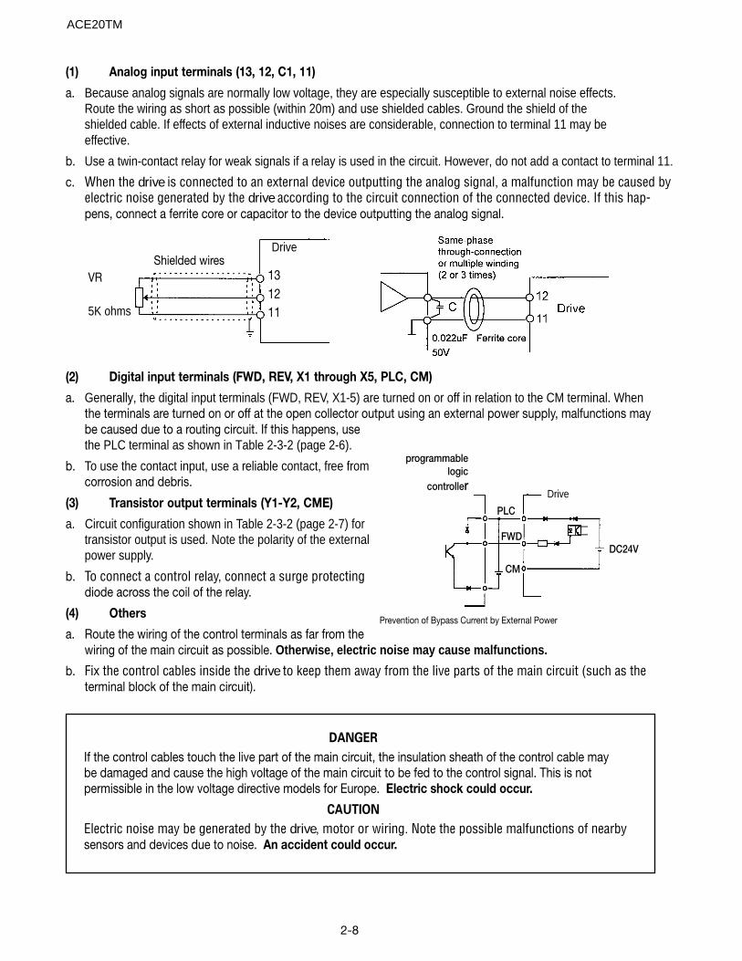
(1) Analog input terminals (13, 12, C1, 11)
a. Because analog signals are normally low voltage, they are especially susceptible to external noise effects.Route the wiring as short as possible (within 20m) and use shielded cables. Ground the shield of theshielded cable. If effects of external inductive noises are considerable, connection to terminal 11 may beeffective.
b. Use a twin-contact relay for weak signals if a relay is used in the circuit. However, do not add a contact to terminal 11.
c. When the drive is connected to an external device outputting the analog signal, a malfunction may be caused byelectric noise generated by the drive according to the circuit connection of the connected device. If this hap-pens, connect a ferrite core or capacitor to the device outputting the analog signal.
(2) Digital input terminals (FWD, REV, X1 through X5, PLC, CM)
a. Generally, the digital input terminals (FWD, REV, X1-5) are turned on or off in relation to the CM terminal. Whenthe terminals are turned on or off at the open collector output using an external power supply, malfunctions maybe caused due to a routing circuit. If this happens, usethe PLC terminal as shown in Table 2-3-2 (page 2-6).
b. To use the contact input, use a reliable contact, free fromcorrosion and debris.
(3) Transistor output terminals (Y1-Y2, CME)
a. Circuit configuration shown in Table 2-3-2 (page 2-7) fortransistor output is used. Note the polarity of the externalpower supply.
b. To connect a control relay, connect a surge protectingdiode across the coil of the relay.
(4) Others
a. Route the wiring of the control terminals as far from thewiring of the main circuit as possible. Otherwise, electric noise may cause malfunctions.
b. Fix the control cables inside the drive to keep them away from the live parts of the main circuit (such as theterminal block of the main circuit).
VR
5K ohms
Drive
131211
Shielded wires
Prevention of Bypass Current by External Power
Drive
programmablelogic
controller
DC24V
PLC
FWD
CM
DANGER
If the control cables touch the live part of the main circuit, the insulation sheath of the control cable maybe damaged and cause the high voltage of the main circuit to be fed to the control signal. This is notpermissible in the low voltage directive models for Europe. Electric shock could occur.
CAUTION
Electric noise may be generated by the drive, motor or wiring. Note the possible malfunctions of nearbysensors and devices due to noise. An accident could occur.
ACE20TM
2-9
ACE202V3P0001N1
ACE202V3P0002N1
ACE202V3P0005N1
ACE202V3P0010N1
Screw size: M3.5
ACE202V3P0020N1
ACE202V3P0030N1
ACE204V3P0005N1
ACE204V3P0010N1
ACE204V3P0020N1 Screw size: M4
ACE204V3P0030N1
ACE202V3P0050N1
ACE202V3P0075N1
ACE202V3P0100N1
ACE204V3P0050N1
ACE204V3P0075N1 Screw size: M4
ACE204V3P0100N1
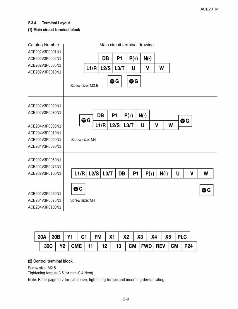
(2) Control terminal block
Screw size: M2.5Tightening torque: 3.5 lb•Inch (0.4 N•m)
Note: Refer page to v for cable size, tightening torque and incoming device rating.
2.3.4 Terminal Layout
(1) Main circuit terminal block
Catalog Number Main circuit terminal drawing
DB P1 P(+) N(-)
L1/R L2/S L3/T U V W
G
DB P1 P(+) N(-)
L1/R L2/S L3/T U V WGG
G
L1/R L2/S L3/T DB P1 P(+) N(-) U V W
G G
30A 30B Y1 C1 FM X1 X2 X3 X4 X5 PLC
30C Y2 CME 11 12 13 CM FWD REV CM P24
ACE20TM

2-10
Notes:
ACE20TM
3-1
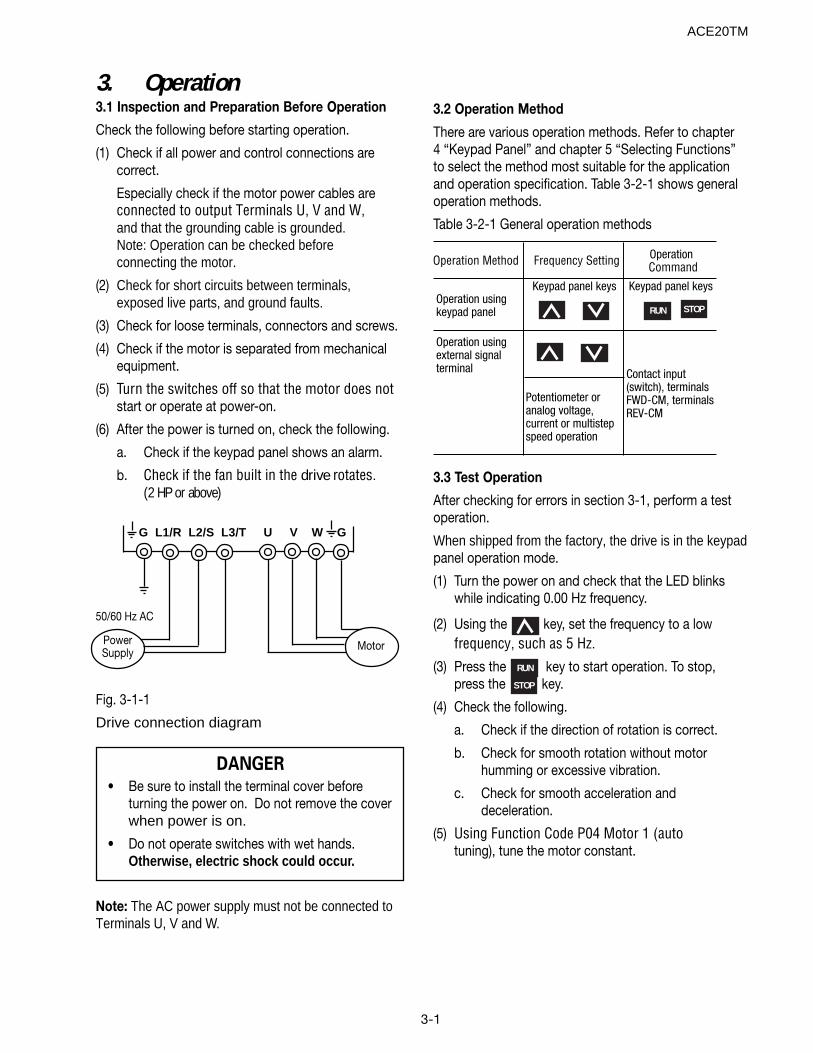
3. Operation3.1 Inspection and Preparation Before Operation
Check the following before starting operation.
(1) Check if all power and control connections arecorrect.
Especially check if the motor power cables areconnected to output Terminals U, V and W,and that the grounding cable is grounded.Note: Operation can be checked beforeconnecting the motor.
(2) Check for short circuits between terminals,exposed live parts, and ground faults.
(3) Check for loose terminals, connectors and screws.
(4) Check if the motor is separated from mechanicalequipment.
(5) Turn the switches off so that the motor does notstart or operate at power-on.
(6) After the power is turned on, check the following.
a. Check if the keypad panel shows an alarm.
b. Check if the fan built in the drive rotates.(2 HP or above)
Fig. 3-1-1
Drive connection diagram
3.2 Operation Method
There are various operation methods. Refer to chapter4 “Keypad Panel” and chapter 5 “Selecting Functions”to select the method most suitable for the applicationand operation specification. Table 3-2-1 shows generaloperation methods.
Table 3-2-1 General operation methods
3.3 Test Operation
After checking for errors in section 3-1, perform a testoperation.
When shipped from the factory, the drive is in the keypadpanel operation mode.
(1) Turn the power on and check that the LED blinkswhile indicating 0.00 Hz frequency.
(2) Using the key, set the frequency to a lowfrequency, such as 5 Hz.
(3) Press the RUN key to start operation. To stop,press the STOP key.
(4) Check the following.
a. Check if the direction of rotation is correct.
b. Check for smooth rotation without motorhumming or excessive vibration.
c. Check for smooth acceleration anddeceleration.
(5) Using Function Code P04 Motor 1 (autotuning), tune the motor constant.
Operation Method Frequency Setting Operation Command
Operation using keypad panel
Keypad panel keys Keypad panel keys
Operation using external signal terminal
Potentiometer or analog voltage, current or multistep speed operation
Contact input (switch), terminals FWD-CM, terminals REV-CM
RUN STOP
DANGER• Be sure to install the terminal cover before
turning the power on. Do not remove the coverwhen power is on.
• Do not operate switches with wet hands.Otherwise, electric shock could occur.
G L1/R L2/S L3/T U V W G
PowerSupply
Motor
Note: The AC power supply must not be connected toTerminals U, V and W.
50/60 Hz AC
ACE20TM
3-2
If no abnormality is found, increase the operationfrequency to check for full speed-range operation.
After checking for correct operation during the abovetest operation, start normal operation.
Caution 1:If any operation abnormality is found,immediately stop operation anddetermine the cause by referring to chapter 7,Troubleshooting.
Caution 2:If voltage is applied to the L1/R, L2/S and L3/T main circuit power supply terminals, evenafter the motor stops, the drive outputTerminals U, V and W will have voltagepresent and can cause electric shockwhen the terminals are touched. Also, thesmoothing capacitor does not dischargeimmediately after the power is turned off.It takes time for the capacitor to dis-charge and voltage is present.
Before touching an electric circuit, afterturning the power off, check that the chargelamp is not lit and check for safe voltage usinga multimeter by checking the various powercircuit connections.
ACE20TM
4-1
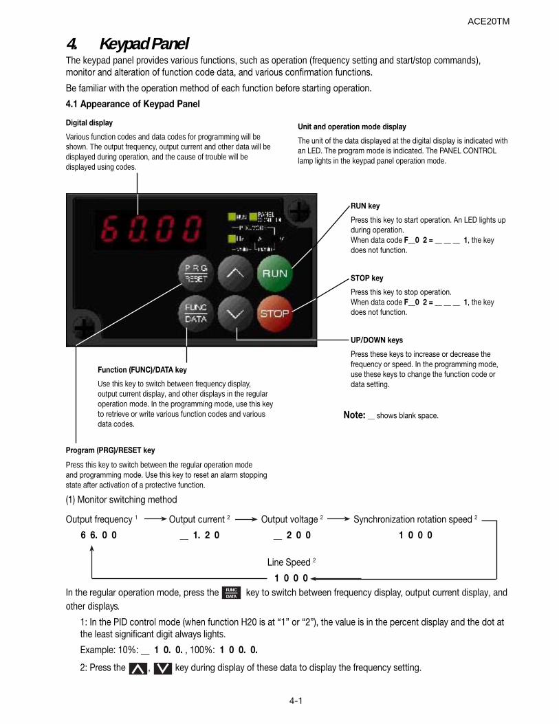
4. Keypad PanelThe keypad panel provides various functions, such as operation (frequency setting and start/stop commands),monitor and alteration of function code data, and various confirmation functions.
Be familiar with the operation method of each function before starting operation.
4.1 Appearance of Keypad Panel
In the regular operation mode, press the FUNCDATA key to switch between frequency display, output current display, and
other displays.
1: In the PID control mode (when function H20 is at “1” or “2”), the value is in the percent display and the dot atthe least significant digit always lights.
Example: 10%: __ 1 0. 0. , 100%: 1 0 0. 0.
2: Press the , key during display of these data to display the frequency setting.
Digital display
Various function codes and data codes for programming will beshown. The output frequency, output current and other data will bedisplayed during operation, and the cause of trouble will bedisplayed using codes.
Unit and operation mode display
The unit of the data displayed at the digital display is indicated withan LED. The program mode is indicated. The PANEL CONTROLlamp lights in the keypad panel operation mode.
RUN key
Press this key to start operation. An LED lights upduring operation.When data code F__0 2 = __ __ __ 1, the keydoes not function.
STOP key
Press this key to stop operation.When data code F__0 2 = __ __ __ 1, the keydoes not function.
UP/DOWN keys
Press these keys to increase or decrease thefrequency or speed. In the programming mode,use these keys to change the function code ordata setting.
Program (PRG)/RESET key
Press this key to switch between the regular operation modeand programming mode. Use this key to reset an alarm stoppingstate after activation of a protective function.
(1) Monitor switching method
Function (FUNC)/DATA key
Use this key to switch between frequency display,output current display, and other displays in the regularoperation mode. In the programming mode, use this keyto retrieve or write various function codes and variousdata codes.
Note: __ shows blank space.
Output frequency 1 Output current 2 Output voltage 2 Synchronization rotation speed 2
6 6. 0 0 __ 1. 2 0 __ 2 0 0 1 0 0 0
Line Speed 2
1 0 0 0
ACE20TM
4-2
(2) Stopping
Operation is started when the RUN is pressed, and is stopped when the STOP is pressed when function F — 0 2is set to — — — 0, — — — 1 or — — — 3.
The direction rotation is Forward with FWD-CM ON, and Reverse with REV-CM ON.
(3) Changing the frequency
The frequency increases when the key is pressed and decreases when the key is pressed while functionF — 0 1 is set to — — — 0.
The speed change increases when the FUNCDATA key is pressed at the same time as the or
Note: Do not turn the power off for five seconds after performing a monitor change or function setting; otherwise,Er1 will occur.
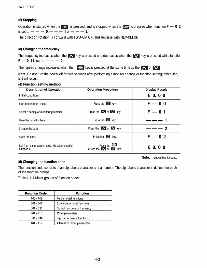
(4) Function setting method
(5) Changing the function code
The function code consists of an alphabetic character and a number. The alphabetic character is defined for eachof the function groups.
Table 4-1-1 Major groups of function codes
Description of Operation Operation Procedure Display Result
Initial condition. 6 0. 0 0
Start the program mode. Press the key. F — 0 0
Select a setting or monitoring function. Press the or key. F — 0 1
Have the data displayed. Press the key. — — — 1
Change the data. Press the or key. — — — 2
Store the data. Press the key. F — 0 2
Exit from the program mode. (Or select another function.)
Press the (Press the or key) 6 0. 0 0
FUNCDATA
FUNCDATA
PRGRESET
PRGRESET
Function Code Function
F00 - F42 Fundamental functions
E01 - E41 Extension terminal functions
C01 - C33 Control functions of frequency
P01 - P10 Motor parameters
H01 - H46 High performance functions
A01 - A19 Alternative motor parameters
Note: __ shows blank space.
ACE20TM
4-3
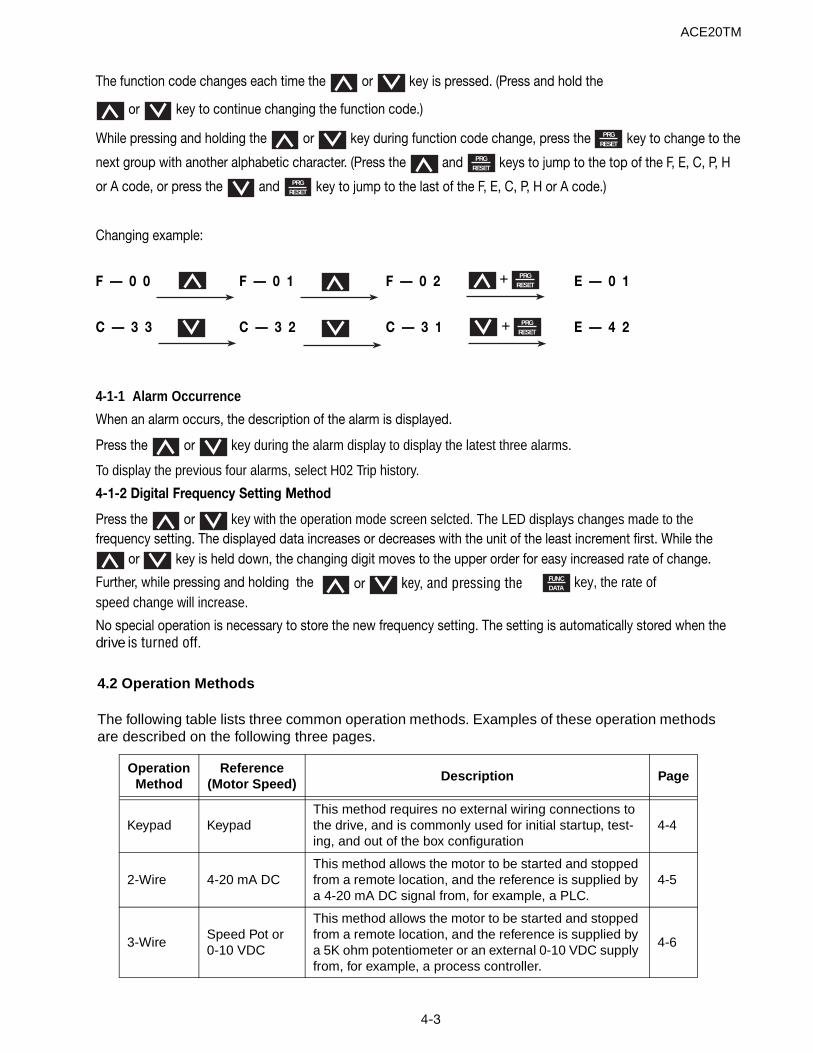
The function code changes each time the or key is pressed. (Press and hold the
or key to continue changing the function code.)
While pressing and holding the or key during function code change, press the PRGRESET key to change to the
next group with another alphabetic character. (Press the and PRGRESET keys to jump to the top of the F, E, C, P, H
or A code, or press the and PRGRESET key to jump to the last of the F, E, C, P, H or A code.)
Changing example:
F — 0 0 F — 0 1 F — 0 2 E — 0 1
C — 3 3 C — 3 2 C — 3 1 E — 4 2
4-1-1 Alarm Occurrence
When an alarm occurs, the description of the alarm is displayed.
Press the or key during the alarm display to display the latest three alarms.
To display the previous four alarms, select H02 Trip history.
4-1-2 Digital Frequency Setting Method
Press the or key with the operation mode screen selcted. The LED displays changes made to thefrequency setting. The displayed data increases or decreases with the unit of the least increment first. While the
or key is held down, the changing digit moves to the upper order for easy increased rate of change.
Further, while pressing and holding the or key, and pressing the FUNCDATA key, the rate of
speed change will increase.
No special operation is necessary to store the new frequency setting. The setting is automatically stored when thedrive is turned off.
PRGRESET
PRGRESET
+
+
ACE20TM
4.2 Operation Methods
The following table lists three common operation methods. Examples of these operation methods are described on the following three pages.
OperationMethod
Reference(Motor Speed)
Description Page
Keypad KeypadThis method requires no external wiring connections to the drive, and is commonly used for initial startup, test-ing, and out of the box configuration
4-4
2-Wire 4-20 mA DCThis method allows the motor to be started and stopped from a remote location, and the reference is supplied by a 4-20 mA DC signal from, for example, a PLC.
4-5
3-WireSpeed Pot or0-10 VDC
This method allows the motor to be started and stopped from a remote location, and the reference is supplied by a 5K ohm potentiometer or an external 0-10 VDC supply from, for example, a process controller.
4-6
4-4
ACE20TM
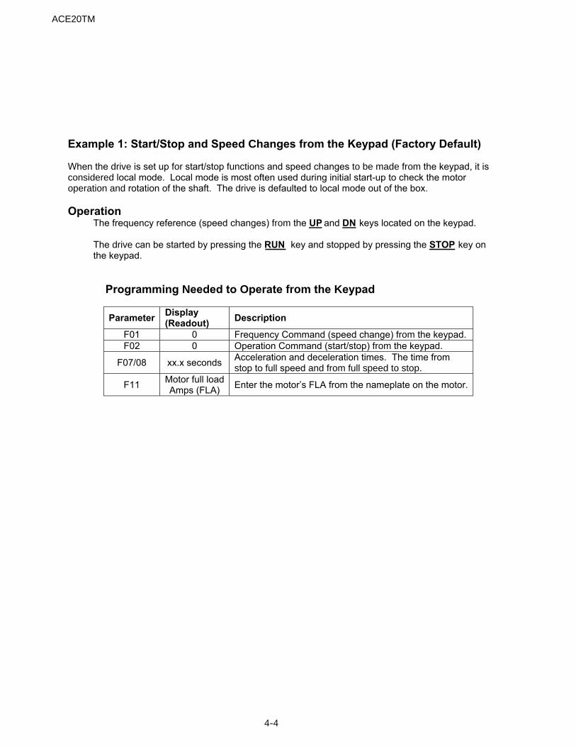
Example 1: Start/Stop and Speed Changes from the Keypad (Factory Default) When the drive is set up for start/stop functions and speed changes to be made from the keypad, it isconsidered local mode. Local mode is most often used during initial start-up to check the motoroperation and rotation of the shaft. The drive is defaulted to local mode out of the box. Operation
The frequency reference (speed changes) from the UP and DN keys located on the keypad. The drive can be started by pressing the RUN key and stopped by pressing the STOP key on the keypad.
Programming Needed to Operate from the Keypad
Parameter Display (Readout) Description
F01 0 Frequency Command (speed change) from the keypad. F02 0 Operation Command (start/stop) from the keypad.
F07/08 xx.x seconds Acceleration and deceleration times. The time from stop to full speed and from full speed to stop.
F11 Motor full load Amps (FLA) Enter the motor’s FLA from the nameplate on the motor.
ACE20TM
4-5
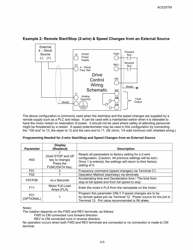
Example 2: Remote Start/Stop (2-wire) & Speed Changes from an External Source
External 4 – 20mA Source (-) (+)
Forward RunFWD 10VDC
Power Supply
13
Reverse RunREV C1
DriveControl Wiring
Schematic
4 – 20mA Freq. Ref.
CM
Shield 30C
30B
30A
11 Analog
Common Fault Output Shield
The above configuration is commonly used when the start/stop and the speed changes are supplied by a remote supply such as a PLC and relays. It can be used with a maintained switch when it is desirable to have the motor restart on restoration of power. It should not be used where safety of attending personnel might be threatened by a restart. A speed potentiometer may be used in this configuration by connecting the “100 end” to 13, the wiper to 12 and the zero end to 11. (5k ohms, 1/4 watt minimum with shielded wiring.) Programming Needed for 2-wire Start/Stop and Speed Changes from an External Source
Parameter Display
(Readout) Description
H03
1 (Hold STOP and UP
key to change) Press the
FUNC/DATA Key.
Resets all parameters to factory setting for a 2-wire configuration. (Caution: All previous settings will be lost. ) Once 1 is entered, the settings will return to their factory setting of 0.
F01 2 Frequency command (speed changes) via Terminal C1. F02 1 Operation Method (start/stop) via terminals.
F07/F08 xx.x Seconds Accelerating time and Deceleration time / The time from stop to full speed and from full speed to stop.
F11 Motor Full Load Amps (FLA) Enter the motor’s FLA from the nameplate on the motor.
F01 (OPTIONAL) 1
Program this parameter ONLY if speed changes are to be by remote speed pot via Terminal 12. Power source for the pot is Terminal 13. Pot value recommended is 5K ohms.ohms.
Notes: The rotation depends on the FWD and REV terminals, as follows:
FWD to CM connected runs forward direction. REV to CM connected runs in reverse direction.
No operation occurs when both FWD and REV terminals are connected or no connection is made to CM terminal.
4-6
ACE20TM
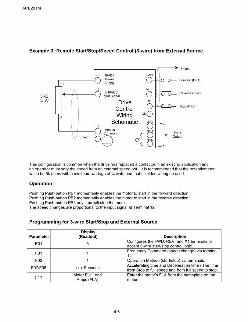
Example 3: Remote Start/Stop/Speed Control (3-wire) from External Source
Shield
FWD 10VDC Power Supply
13 Forward (PB1)
100 REV 12
0-10VDC Input Signal
Reverse (PB2) 5KΩ ¼ W Drive
Control Wiring
Schematic
X1 Stop (PB3)
CM
30C
30B
30A
0
11 Analog
Common Fault Output Shield
This configuration is common when the drive has replaced a contactor in an existing application and an operator must vary the speed from an external speed pot. It is recommended that the potentiometer value be 5k ohms with a minimum wattage of ¼ watt, and that shielded wiring be used. Operation Pushing Push-button PB1 momentarily enables the motor to start in the forward direction. Pushing Push-button PB2 momentarily enables the motor to start in the reverse direction. Pushing Push-button PB3 any time will stop the motor. The speed changes are proportional to the input signal at Terminal 12. Programming for 3-wire Start/Stop and External Source
Parameter Display
(Readout) Description
E01 5 Configures the FWD, REV, and X1 terminals to accept 3-wire start/stop control logic.
F01 1 Frequency Command (speed change) via terminal 12.
F02 1 Operation Method (start/stop) via terminals.
F07/F08 xx.x Seconds Accelerating time and Deceleration time / The time from Stop to full speed and from full speed to stop.
F11 Motor Full Load Amps (FLA)
Enter the motor’s FLA from the nameplate on the motor.
ACE20TM
4-7
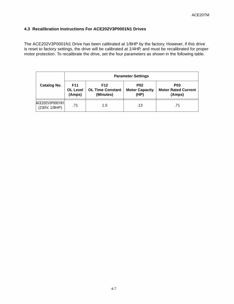
4.3 Recalibration Instructions For ACE202V3P0001N1 Drives
The ACE202V3P0001N1 Drive has been calibrated at 1/8HP by the factory. However, if this driveis reset to factory settings, the drive will be calibrated at 1/4HP, and must be recalibrated for propermotor protection. To recalibrate the drive, set the four parameters as shown in the following table.
Catalog No.
Parameter Settings
F11OL Level(Amps)
F12OL Time Constant
(Minutes)
P02Motor Capacity
(HP)
P03Motor Rated Current
(Amps)
ACE202V3P0001N1(230V, 1/8HP)
.71 1.5 .13 .71

4-8
Notes:
ACE20TM
5-1
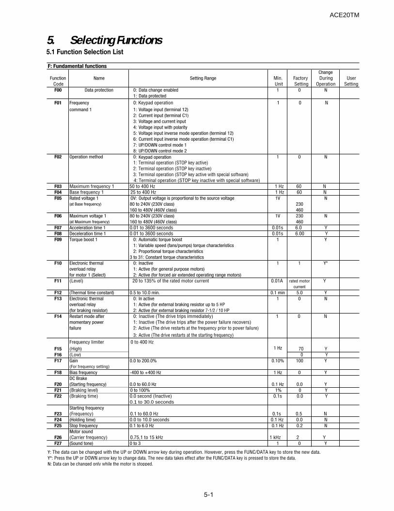
5. Selecting Functions5.1 Function Selection List
ACE20TM
F: Fundamental functionsChange
Function Name Setting Range Min. Factory During UserCode Unit Setting Operation SettingF00 Data protection 0: Data change enabled 1 0 N
1: Data protected
F01 Frequency 0: Keypad operation 1 0 Ncommand 1 1: Voltage input (terminal 12)
2: Current input (terminal C1)3: Voltage and current input4: Voltage input with polarity5: Voltage input inverse mode operation (terminal 12)6: Current input inverse mode operation (terminal C1)7: UP/DOWN control mode 18: UP/DOWN control mode 2
F02 Operation method 0: Keypad operation 1 0 N1: Terminal operation (STOP key active)2: Terminal operation (STOP key inactive)3: Terminal operation (STOP key active with special software) 4: Terminal operation (STOP key inactive with special software)
F03 Maximum frequency 1 50 to 400 Hz 1 Hz 60 NF04 Base frequency 1 25 to 400 Hz 1 Hz 60 NF05 Rated voltage 1 OV: Output voltage is proportional to the source voltage 1V N
(at Base frequency) 80 to 240V (230V class) 230160 to 480V (460V class) 460
F06 Maximum voltage 1 80 to 240V (230V class) 1V 230 N(at Maximum frequency) 160 to 480V (460V class) 460
F07 Acceleration time 1 0.01 to 3600 seconds 0.01s 6.0 YF08 Deceleration time 1 0.01 to 3600 seconds 0.01s 6.00 YF09 Torque boost 1 0: Automatic torque boost 1 Y
1: Variable speed (fans/pumps) torque characteristics2: Proportional torque characteristics
3 to 31: Constant torque characteristicsF10 Electronic thermal 0: Inactive 1 1 Y*
overload relay 1: Active (for general purpose motors) for motor 1 (Select) 2: Active (for forced air extended operating range motors)
F11 (Level) 20 to 135% of the rated motor current 0.01A rated motor Ycurrent
F12 (Thermal time constant) 0.5 to 10.0 min. 0.1 min 5.0 YF13 Electronic thermal 0: In active 1 0 N
overload relay 1: Active (for external braking resistor up to 5 HP(for braking resistor) 2: Active (for external braking resistor 7-1/2 / 10 HP
F14 Restart mode after 0: Inactive (The drive trips immediately) 1 0 Nmomentary power 1: Inactive (The drive trips after the power failure recovers)failure 2: Active (The drive restarts at the frequency prior to power failure)
3: Active (The drive restarts at the starting frequency)Frequency limiter 0 to 400 Hz
F15 (High) 70 YF16 (Low) 0 YF17 Gain 0.0 to 200.0% 0.10% 100 Y
(For frequency setting)F18 Bias frequency -400 to +400 Hz 1 Hz 0 Y
DC Brake F20 (Starting frequency) 0.0 to 60.0 Hz 0.1 Hz 0.0 YF21 (Braking level) 0 to 100% 1% 0 YF22 (Braking time) 0.0 second (Inactive) 0.1s 0.0 Y
0.1 to 30.0 secondsStarting frequency
F23 (Frequency) 0.1 to 60.0 Hz 0.1s 0.5 NF24 (Holding time) 0.0 to 10.0 seconds 0.1 Hz 0.0 NF25 Stop frequency 0.1 to 6.0 Hz 0.1 Hz 0.2 N
Motor soundF26 (Carrier frequency) 0.75,1 to 15 kHz 1 kHz 2 YF27 (Sound tone) 0 to 3 1 0 Y
Y: The data can be changed with the UP or DOWN arrow key during operation. However, press the FUNC/DATA key to store the new data.Y*: Press the UP or DOWN arrow key to change data. The new data takes effect after the FUNC/DATA key is pressed to store the data.N: Data can be changed only while the motor is stopped.
1 Hz
5-2
ACE20TM
Y: The data can be changed with the UP or DOWN arrow key during operation. However, press the FUNC/DATA key to store the new dat a.Y*: Press the UP or DOWN arrow key to change the data. The new data will take effect after the FUNC/DATA key is pressed to store the data.N: The data can be changed only while the motor is stopped.
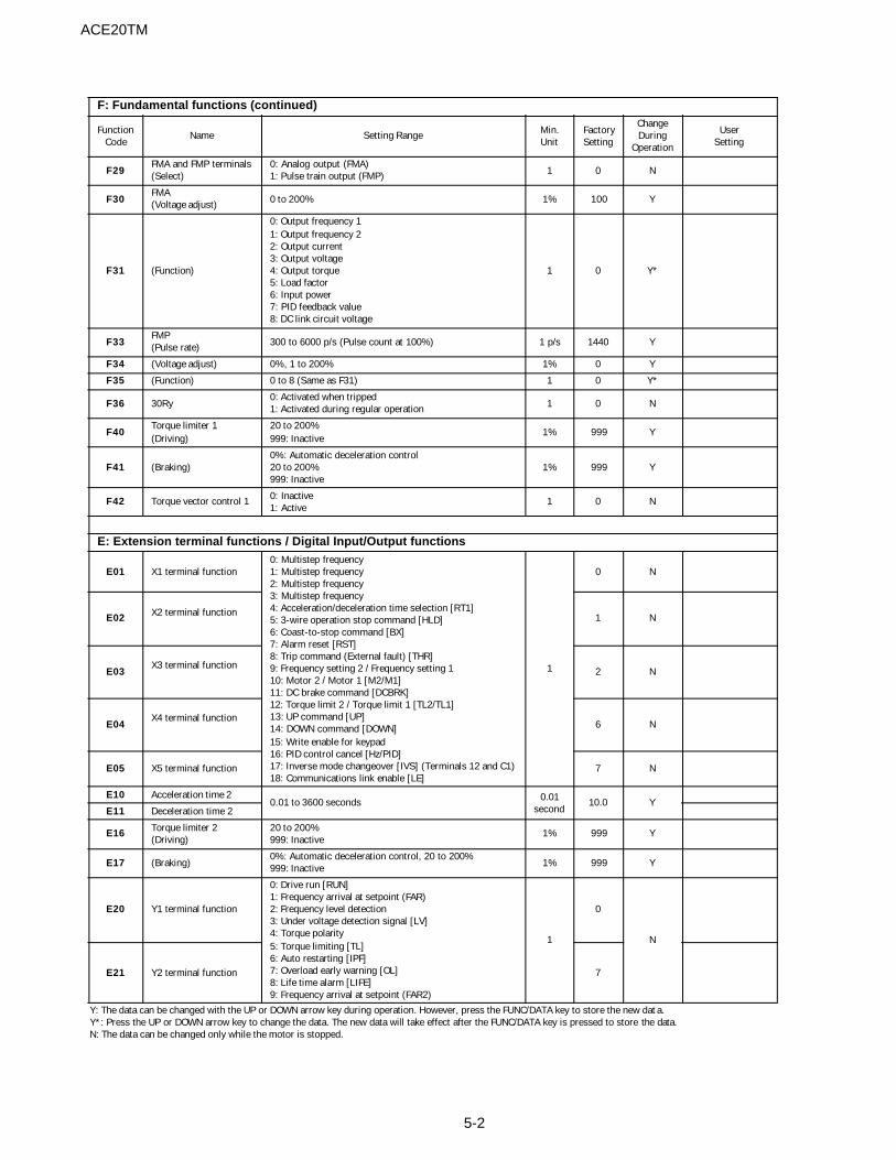
F: Fundamental functions (continued)
FunctionCode
Name Setting Range Min.Unit
FactorySetting
ChangeDuring
Operation
UserSetting
F29FMA and FMP terminals(Select)
0: Analog output (FMA)1: Pulse train output (FMP) 1 0 N
F30FMA(Voltage adjust) 0 to 200% 1% 100 Y
F31 (Function)
0: Output frequency 11: Output frequency 22: Output current3: Output voltage4: Output torque5: Load factor6: Input power7: PID feedback value8: DC link circuit voltage
1 0 Y*
F33FMP(Pulse rate) 300 to 6000 p/s (Pulse count at 100%) 1 p/s 1440 Y
F34 (Voltage adjust) 0%, 1 to 200% 1% 0 Y
F35 (Function) 0 to 8 (Same as F31) 1 0 Y*
F36 30Ry0: Activated when tripped1: Activated during regular operation 1 0 N
F40Torque limiter 1(Driving)
20 to 200%999: Inactive
1% 999 Y
F41 (Braking)0%: Automatic deceleration control20 to 200%999: Inactive
1% 999 Y
F42 Torque vector control 1 0: Inactive1: Active
1 0 N
E: Extension terminal functions / Digital Input/Output functions
E01 X1 terminal function0: Multistep frequency1: Multistep frequency2: Multistep frequency3: Multistep frequency4: Acceleration/deceleration time selection [RT1]5: 3-wire operation stop command [HLD]6: Coast-to-stop command [BX]7: Alarm reset [RST]8: Trip command (External fault) [THR]9: Frequency setting 2 / Frequency setting 110: Motor 2 / Motor 1 [M2/M1]11: DC brake command [DCBRK]12: Torque limit 2 / Torque limit 1 [TL2/TL1]13: UP command [UP]14: DOWN command [DOWN]15: Write enable for keypad16: PID control cancel [Hz/PID]17: Inverse mode changeover [IVS] (Terminals 12 and C1)18: Communications link enable [LE]
1
0 N
E02 X2 terminal function 1 N
E03X3 terminal function
2 N
E04X4 terminal function
6 N
E05 X5 terminal function 7 N
E10 Acceleration time 20.01 to 3600 seconds 0.01
second10.0 Y
E11 Deceleration time 2
E16 Torque limiter 2(Driving)
20 to 200%999: Inactive
1% 999 Y
E17 (Braking)0%: Automatic deceleration control, 20 to 200%999: Inactive 1% 999 Y
E20 Y1 terminal function
0: Drive run [RUN]1: Frequency arrival at setpoint (FAR)2: Frequency level detection3: Under voltage detection signal [LV]4: Torque polarity5: Torque limiting [TL]6: Auto restarting [IPF]7: Overload early warning [OL]8: Life time alarm [LIFE]9: Frequency arrival at setpoint (FAR2)
1
0
N
E21 Y2 terminal function 7

5-35-3
ACE20TM
Y: The data can be changed with the UP or DOWN arrow key during operation. However, press the FUNC/DATA key to store the new data.Y*: Press the UP or DOWN arrow key to change the data. The new data will take effect after the FUNC/DATA key is pressed to store the data.N: The data can be changed only while the motor is stopped.
E: Extension terminal functions / Digital Input/Output functions (continued)
FunctionCode
Name Setting Range Min.Unit
FactorySetting
ChangeDuring
Operation
UserSetting
E29 Frequency detection delay 0.01 to 10.0 seconds 0.01s 0.10 Y
E30 FAR function signal(Hysteresis) 0.0 to 10.0 Hz 0.1 Hz 2.5 Y
E31 FDT function signal (Level) 0 to 400 Hz 1 Hz 60 YE32 (Hysteresis) 0.0 to 30.0 Hz 0.1 Hz 1.0 Y
E33OL function signal(Mode select)
0: Electronic thermal overload relay1: Output current 1 0 Y*
E34 (Level) 20 to 200% of the rated motor current 0.01ARated motor
currentY
E35 (Timer) 0.0 to 60.0 seconds 0.1s 10.0 YE40 Display (A) 0.00 to 200.0 0.01 0.01 Y
E41 (B) 0.00 to 200.0 0.01 0.00 YE42 LED display 0.0 to 5.0 seconds 0.1s 0.5 Y
C: Control function of frequency
C01Jump frequency(Jump frequency 1)
0 to 400 Hz1 Hz
0 Y
C02 (Jump frequency 2) 0 Y
C03 (Jump frequency 3) 0 YC04 (Hysteresis) 0 to 30 Hz 3 Y
C05Multistep frequency(Frequency 1)
0.00 to 400.0 Hz 0.01 Hz 0.00 Y
C06 (Frequency 2)
C07 (Frequency 3)C08 (Frequency 4)C09 (Frequency 5)
C10 (Frequency 6)C11 (Frequency 7)C12 (Frequency 8)
C13 (Frequency 9)C14 (Frequency 10)C15 (Frequency 11)
C16 (Frequency 12)C17 (Frequency 13)C18 (Frequency 14)
C19 (Frequency 15)
C21 Timer operation auto-stop 0: Inactive1: Active
1 0 N
C22 Auto-stop time 0.00 to 3600 seconds 0.01s 0.00 YC30 Frequency command 2 0 to 8 (same as F01) 1 2 N
C31Analog setting signal offset adjustment(Terminal 12)
-5.0 to +5.0% 0.1% 0.0 Y
C32 (Terminal C1) -5.0 to +5.0% 0.1% 0.0 Y
C33 Analog setting signal filter 0.00 to 5.00 seconds 0.01s 0.05 Y
P: Motor parametersP01 Number of motor 1 poles 2 to 14 2 4 N
P02 Motor 1(Capacity)
0.01 to 7.5 HP (5 HP or less)0.01 to 15 HP (7-1/2/10 HP) 0.01 HP
Nominalapplied
motor HPN
P03 (Rated current) 0.00 to 99.9A 0.01A Standard rating
N
P04 (Tuning)0: Inactive1: Active (%R1, %X)2: Active (%R1, %X, lo)
1 0 N
P05 (Online tuning) 0: Inactive1: Active 1 0 N
ACE20TM
5-4
ChangeFunction Name Setting Range Min. Factory During User
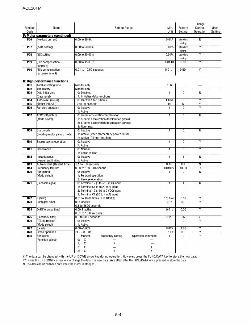
Code Unit Setting Operation SettingP: Motor parameters (continued)
P06 (No-load current) 0.00 to 99.9A 0.01A standard Nrating
P07 (%R1 setting) 0.00 to 50.00% 0.01% standard Yrating
P08 (%X setting 0.00 to 50.00% 0.01% standard Yrating
P09 (Slip compensation 0.00 to 15.0 Hz 0.01 Hz 0.00 Ycontrol 1)
P10 (Slip compensation 0.01 to 10.00 seconds 0.01s 0.50 Yresponse time 1)
H: High performance functionsH01 Total operating time Monitor only 10h 0 —H02 Trip history Monitor only — — —H03 Data initializing 0: Disabled 1 0 N
(Data reset) 1: Initialize data functionsH04 Auto-reset (Times) 0: Inactive 1 to 10 times 1 time 0 YH05 (Reset interval) 2 to 20 seconds 1s 5 YH06 Fan stop operation 0: Inactive 1 0 Y
1: ActiveH07 ACC/DEC pattern 0: Linear acceleration/deceleration 1 0 N
(Mode select) 1: S-curve acceleration/deceleration (weak)2: S-curve acceleration/deceleration (strong)3: Non-linear
H09 Start mode 0: Inactive 1 0 N(Rotating motor pickup mode) 1: Active (After momentary power failure)
2: Active (All start modes)H10 Energy saving operation 0: Inactive 1 0 Y
1: ActiveH11 Decel mode 0: Normal 1 0 Y
1: Coast-to-stopH12 Instantaneous 0: Inactive 1 1 N
overcurrent limiting 1: ActiveH13 Auto-restart (Restart time) 0.1 to 5.0 seconds 0.1s 0.1 NH14 Frequency fall rate 0.00 to 100.0 Hz/second 0.01Hz/s 10.00 YH20 PID control 0: Inactive 1 0 N
(Mode select) 1: Forward operation2: Reverse operation
H21 (Feeback signal) 0: Terminal 12 (0 to +10 VDC) input 1 1 N1: Terminal C1 (4 to 20 mA) input2: Terminal 12 (+10 to 0 VDC) input3: Terminal C1 (20 to 4 mA) input
H22 P (Gain) 0.01 to 10.00 times (1 to 1000%) 0.01 time 0.10 YH23 I (Integral time) 0.0: Inactive 0.1s 0.0 Y
0.1 to 3600 secondsH24 D (Differential time) 0.00: Inactive 0.01s 0.00 Y
0.01 to 10.0 secondsH25 (Feedback filter) 0.0 to 60.0 seconds 0.1s 0.5 YH26 PTC thermistor 0: Inactive 0 Y
(Mode select) 1: ActiveH27 (Level) 0.00--5.00V 0.01V 1.60 YH28 Droop operation -9.9 --0.0 Hz 0.1 Hz 0.0 YH30 Serial link Monitor Frequency setting Operation command 1 0 Y
(Function select) 0: X — —1: X X —2: X — X3: X X X
Y: The data can be changed with the UP or DOWN arrow key during operation. However, press the FUNC/DATA key to store the new data.Y*: Press the UP or DOWN arrow key to change the data. The new data takes effect after the FUNC/DATA key is pressed to store the data.N: The data can be changed only while the motor is stopped.
5-5
ACE20TM
ChangeFunction Name Setting Range Min. Factory During User
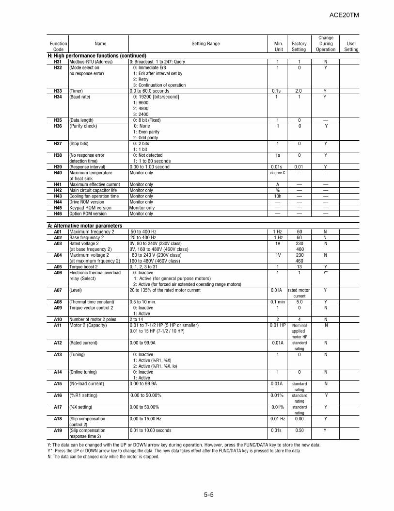
Code Unit Setting Operation SettingH: High performance functions (continued)
H31 Modbus-RTU (Address) 0: Broadcast 1 to 247: Query 1 1 NH32 (Mode select on 0: Immediate Er8 1 0 Y
no response error) 1: Er8 after interval set by2: Retry3: Continuation of operation
H33 (Timer) 0.0 to 60.0 seconds 0.1s 2.0 YH34 (Baud rate) 0: 19200 [bits/second] 1 1 Y
1: 96002: 48003: 2400
H35 (Data length) 0: 8 bit (Fixed) 1 0 —H36 (Parity check) 0: None 1 0 Y
1: Even parity2: Odd parity
H37 (Stop bits) 0: 2 bits 1 0 Y1: 1 bit
H38 (No response error 0: Not detected 1s 0 Ydetection time) 1: 1 to 60 seconds
H39 (Response interval) 0.00 to 1.00 second 0.01s 0.01 YH40 Maximum temperature Monitor only degree C — —
of heat sinkH41 Maximum effective current Monitor only A — —H42 Main circuit capacitor life Monitor only % — —H43 Cooling fan operation time Monitor only 10h — —H44 Drive ROM version Monitor only — — —H45 Keypad ROM version Monitor only — — —H46 Option ROM version Monitor only — — —
A: Alternative motor parametersA01 Maximum frequency 2 50 to 400 Hz 1 Hz 60 NA02 Base frequency 2 25 to 400 Hz 1 Hz 60 NA03 Rated voltage 2 0V, 80 to 240V (230V class) 1V 230 N
(at base frequency 2) 0V, 160 to 480V (460V class) 460A04 Maximum voltage 2 80 to 240 V (230V class) 1V 230 N
(at maximum frquency 2) 160 to 480V (460V class) 460A05 Torque boost 2 0, 1, 2, 3 to 31 1 13 YA06 Electronic thermal overload 0: Inactive 1 1 Y*
relay (Select) 1: Active (for general purpose motors)2: Active (for forced air extended operating range motors)
A07 (Level) 20 to 135% of the rated motor current 0.01A rated motor Ycurrent
A08 (Thermal time constant) 0.5 to 10 min. 0.1 min 5.0 YA09 Torque vector control 2 0: Inactive 1 0 N
1: ActiveA10 Number of motor 2 poles 2 to 14 2 4 NA11 Motor 2 (Capacity) 0.01 to 7-1/2 HP (5 HP or smaller) 0.01 HP Nominal N
0.01 to 15 HP (7-1/2 / 10 HP) appliedmotor HP
A12 (Rated current) 0.00 to 99.9A 0.01A standard Nrating
A13 (Tuning) 0: Inactive 1 0 N1: Active (%R1, %X)2: Active (%R1, %X, Io)
A14 (Online tuning) 0: Inactive 1 0 N1: Active
A15 (No-load current) 0.00 to 99.9A 0.01A standard Nrating
A16 (%R1 setting) 0.00 to 50.00% 0.01% standard Yrating
A17 (%X setting) 0.00 to 50.00% 0.01% standard Yrating
A18 (Slip compensation 0.00 to 15.00 Hz 0.01 Hz 0.00 Ycontrol 2)
A19 (Slip compensation 0.01 to 10.00 seconds 0.01s 0.50 Yresponse time 2)
Y: The data can be changed with the UP or DOWN arrow key during operation. However, press the FUNC/DATA key to store the new data.Y*: Press the UP or DOWN arrow key to change the data. The new data takes effect after the FUNC/DATA key is pressed to store the data.N: The data can be changed only while the motor is stopped.
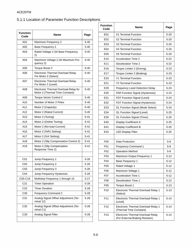
ACE20TM
FunctionCode
Name Page
A01 Maximum Frequency 2 5-40
A02 Base Frequency 2 5-40
A03 Rated Voltage 2 (At Base Frequency 2)
5-40
A04 Maximum Voltage 2 (At Maximum Fre-quency 2)
5-40
A05 Torque Boost 2 5-40
A06 Electronic Thermal Overload Relay For Motor 2 (Select)
5-40
A07 Electronic Thermal Overload Relay For Motor 2 (Level)
5-40
A08 Electronic Thermal Overload Relay for Motor 2 (Thermal Time Constant)
5-40
A09 Torque Vector Control 2 5-40
A10 Number of Motor 2 Poles 5-40
A11 Motor 2 (Capacity) 5-40
A12 Motor 2 (Rated Current) 5-40
A13 Motor 2 (Tuning) 5-41
A14 Motor 2 (Online Tuning) 5-41
A15 Motor 2 (No-load Current) 5-41
A16 Motor 2 (%R1 Setting) 5-41
A17 Motor 2 (%X Setting) 5-41
A18 Motor 2 (Slip Compensation Control 2) 5-41
A19 Motor 2 (Slip Compensation Response Time 2)
5-41
C01 Jump Frequency 1 5-26
C02 Jump Frequency 2 5-26
C03 Jump Frequency 3 5-26
C04 Jump Frequency Hysteresis 5-26
C05-C19 Multistep Frequency 1 through 15 5-27
C21 Timer Operation 5-28
C22 Timer Duration 5-28
C30 Frequency Command 2 5-28
C31 Analog Signal Offset Adjustment (Ter-minal 12)
5-28
C32 Analog Signal Offset Adjustment (Ter-minal C1)
5-28
C33 Analog Signal Filter 5-28
E01 X1 Terminal Function 5-20
E02 X2 Terminal Function 5-20
E03 X3 Terminal Function 5-20
E04 X4 Terminal Function 5-20
E05 X5 Terminal Function 5-20
E10 Acceleration Time 2 5-22
E11 Deceleration Time 2 5-22
E16 Torque Limiter 2 (Driving) 5-23
E17 Torque Limiter 2 (Braking) 5-23
E20 Y1 Terminal Function 5-23
E21 Y2 Terminal Function 5-23
E29 Frequency Level Detection Delay 5-24
E30 FAR Function Signal (Hysteresis) 5-24
E31 FDT Function Signal (Level) 5-24
E32 FDT Function Signal (Hysteresis) 5-24
E33 OL Function Signal (Mode Select) 5-24
E34 OL Function Signal (Level) 5-25
E35 OL Function Signal (Timer) 5-25
E40 Display Coefficient A 5-25
E41 Display Coefficient B 5-25
E42 LED Display Filter 5-25
F00 Data Protection 5-8
F01 Frequency Command 1 5-8
F02 Operation Method 5-8
F03 Maximum Output Frequency 1 5-12
F04 Base Frequency 1 5-12
F05 Rated Voltage 1 5-12
F06 Maximum Voltage 1 5-12
F07 Acceleration Time 1 5-12
F08 Deceleration Time 1 5-12
F09 Torque Boost 1 5-13
F10 Electronic Thermal Overload Relay 1 (Select)
5-13
F11 Electronic Thermal Overload Relay 1 (Level)
5-14
F12 Electronic Thermal Overload Relay 1 (Thermal Time Constant)
5-14
F13 Electronic Thermal Overload Relay (For External Braking Resistor)
5-14
FunctionCode
Name Page
5.1.1 Location of Parameter Function Descriptions
5-6
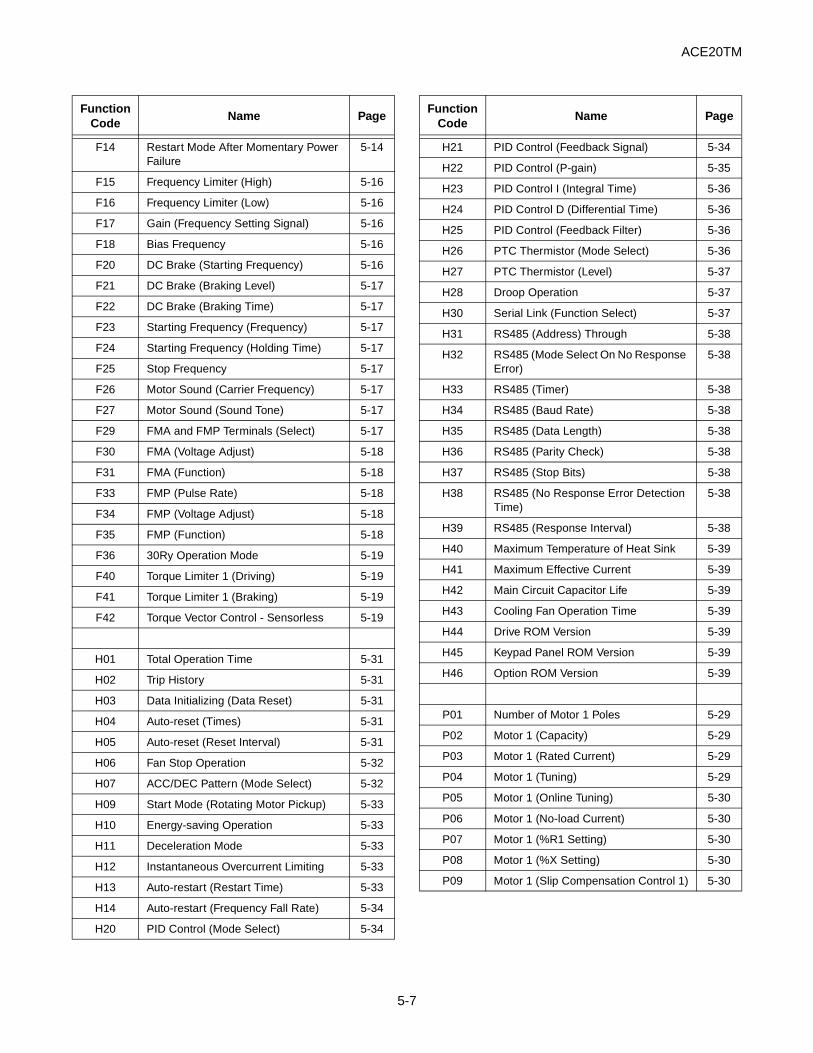
ACE20TM
F14 Restart Mode After Momentary Power Failure
5-14
F15 Frequency Limiter (High) 5-16
F16 Frequency Limiter (Low) 5-16
F17 Gain (Frequency Setting Signal) 5-16
F18 Bias Frequency 5-16
F20 DC Brake (Starting Frequency) 5-16
F21 DC Brake (Braking Level) 5-17
F22 DC Brake (Braking Time) 5-17
F23 Starting Frequency (Frequency) 5-17
F24 Starting Frequency (Holding Time) 5-17
F25 Stop Frequency 5-17
F26 Motor Sound (Carrier Frequency) 5-17
F27 Motor Sound (Sound Tone) 5-17
F29 FMA and FMP Terminals (Select) 5-17
F30 FMA (Voltage Adjust) 5-18
F31 FMA (Function) 5-18
F33 FMP (Pulse Rate) 5-18
F34 FMP (Voltage Adjust) 5-18
F35 FMP (Function) 5-18
F36 30Ry Operation Mode 5-19
F40 Torque Limiter 1 (Driving) 5-19
F41 Torque Limiter 1 (Braking) 5-19
F42 Torque Vector Control - Sensorless 5-19
H01 Total Operation Time 5-31
H02 Trip History 5-31
H03 Data Initializing (Data Reset) 5-31
H04 Auto-reset (Times) 5-31
H05 Auto-reset (Reset Interval) 5-31
H06 Fan Stop Operation 5-32
H07 ACC/DEC Pattern (Mode Select) 5-32
H09 Start Mode (Rotating Motor Pickup) 5-33
H10 Energy-saving Operation 5-33
H11 Deceleration Mode 5-33
H12 Instantaneous Overcurrent Limiting 5-33
H13 Auto-restart (Restart Time) 5-33
H14 Auto-restart (Frequency Fall Rate) 5-34
H20 PID Control (Mode Select) 5-34
FunctionCode
Name Page
H21 PID Control (Feedback Signal) 5-34
H22 PID Control (P-gain) 5-35
H23 PID Control I (Integral Time) 5-36
H24 PID Control D (Differential Time) 5-36
H25 PID Control (Feedback Filter) 5-36
H26 PTC Thermistor (Mode Select) 5-36
H27 PTC Thermistor (Level) 5-37
H28 Droop Operation 5-37
H30 Serial Link (Function Select) 5-37
H31 RS485 (Address) Through 5-38
H32 RS485 (Mode Select On No Response Error)
5-38
H33 RS485 (Timer) 5-38
H34 RS485 (Baud Rate) 5-38
H35 RS485 (Data Length) 5-38
H36 RS485 (Parity Check) 5-38
H37 RS485 (Stop Bits) 5-38
H38 RS485 (No Response Error Detection Time)
5-38
H39 RS485 (Response Interval) 5-38
H40 Maximum Temperature of Heat Sink 5-39
H41 Maximum Effective Current 5-39
H42 Main Circuit Capacitor Life 5-39
H43 Cooling Fan Operation Time 5-39
H44 Drive ROM Version 5-39
H45 Keypad Panel ROM Version 5-39
H46 Option ROM Version 5-39
P01 Number of Motor 1 Poles 5-29
P02 Motor 1 (Capacity) 5-29
P03 Motor 1 (Rated Current) 5-29
P04 Motor 1 (Tuning) 5-29
P05 Motor 1 (Online Tuning) 5-30
P06 Motor 1 (No-load Current) 5-30
P07 Motor 1 (%R1 Setting) 5-30
P08 Motor 1 (%X Setting) 5-30
P09 Motor 1 (Slip Compensation Control 1) 5-30
FunctionCode
Name Page
5-7
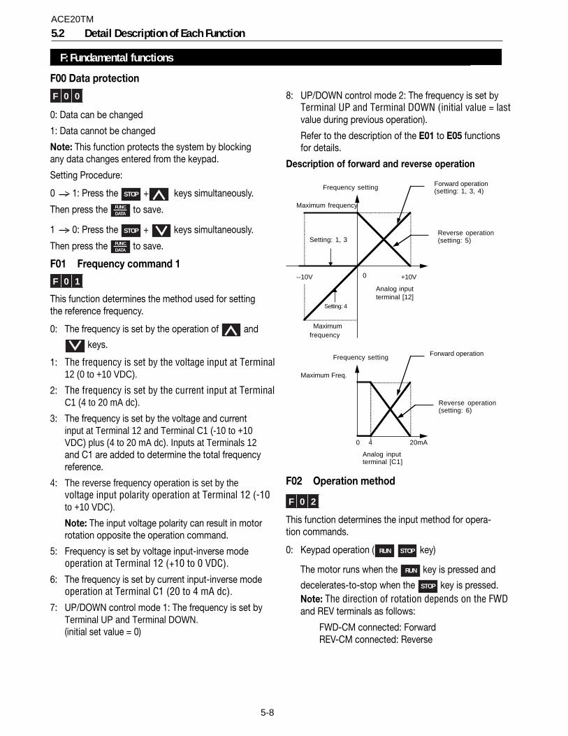
5-8
8: UP/DOWN control mode 2: The frequency is set byTerminal UP and Terminal DOWN (initial value = lastvalue during previous operation).
Refer to the description of the E01 to E05 functionsfor details.
Description of forward and reverse operation
Setting: 1, 3
Setting: 4
--10V 0 +10V
Maximumfrequency
Maximum frequency
Frequency setting
Analog inputterminal [12]
Reverse operation(setting: 5)
Forward operation(setting: 1, 3, 4)
0 4 20mA
Maximum Freq.
Frequency setting
Analog inputterminal [C1]
Reverse operation(setting: 6)
Forward operation
F02 Operation method
F 0 2
This function determines the input method for opera-tion commands.
0: Keypad operation ( RUN STOP key)
The motor runs when the RUN key is pressed and
decelerates-to-stop when the STOP key is pressed.Note: The direction of rotation depends on the FWDand REV terminals as follows:
FWD-CM connected: ForwardREV-CM connected: Reverse
F: Fundamental functions
5.2 Detail Description of Each Function
F00 Data protection
F 0 0
0: Data can be changed
1: Data cannot be changed
Note: This function protects the system by blockingany data changes entered from the keypad.
Setting Procedure:
0 > 1: Press the STOP + keys simultaneously.
Then press the FUNCDATA to save.
1 > 0: Press the STOP + keys simultaneously.
Then press the FUNCDATA to save.
F01 Frequency command 1
F 0 1
This function determines the method used for settingthe reference frequency.
0: The frequency is set by the operation of and
keys.
1: The frequency is set by the voltage input at Terminal12 (0 to +10 VDC).
2: The frequency is set by the current input at TerminalC1 (4 to 20 mA dc).
3: The frequency is set by the voltage and currentinput at Terminal 12 and Terminal C1 (-10 to +10VDC) plus (4 to 20 mA dc). Inputs at Terminals 12and C1 are added to determine the total frequencyreference.
4: The reverse frequency operation is set by thevoltage input polarity operation at Terminal 12 (-10to +10 VDC).
Note: The input voltage polarity can result in motorrotation opposite the operation command.
5: Frequency is set by voltage input-inverse modeoperation at Terminal 12 (+10 to 0 VDC).
6: The frequency is set by current input-inverse modeoperation at Terminal C1 (20 to 4 mA dc).
7: UP/DOWN control mode 1: The frequency is set byTerminal UP and Terminal DOWN.(initial set value = 0)
ACE20TM
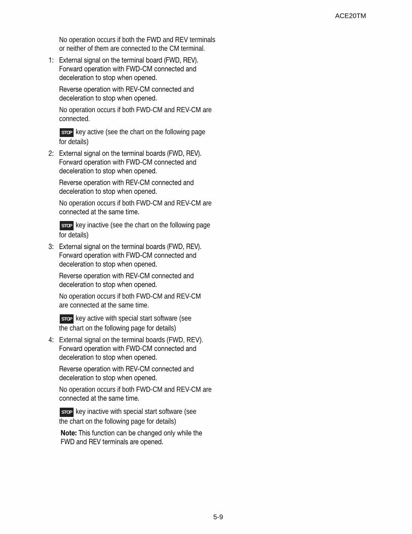
5-9
No operation occurs if both the FWD and REV terminalsor neither of them are connected to the CM terminal.
1: External signal on the terminal board (FWD, REV).Forward operation with FWD-CM connected anddeceleration to stop when opened.
Reverse operation with REV-CM connected anddeceleration to stop when opened.
No operation occurs if both FWD-CM and REV-CM areconnected.
STOP key active (see the chart on the following pagefor details)
2: External signal on the terminal boards (FWD, REV).Forward operation with FWD-CM connected anddeceleration to stop when opened.
Reverse operation with REV-CM connected anddeceleration to stop when opened.
No operation occurs if both FWD-CM and REV-CM areconnected at the same time.
STOP key inactive (see the chart on the following pagefor details)
3: External signal on the terminal boards (FWD, REV).Forward operation with FWD-CM connected anddeceleration to stop when opened.
Reverse operation with REV-CM connected anddeceleration to stop when opened.
No operation occurs if both FWD-CM and REV-CMare connected at the same time.
STOP key active with special start software (seethe chart on the following page for details)
4: External signal on the terminal boards (FWD, REV).Forward operation with FWD-CM connected anddeceleration to stop when opened.
Reverse operation with REV-CM connected anddeceleration to stop when opened.
No operation occurs if both FWD-CM and REV-CM areconnected at the same time.
STOP key inactive with special start software (seethe chart on the following page for details)
Note: This function can be changed only while theFWD and REV terminals are opened.
ACE20TM
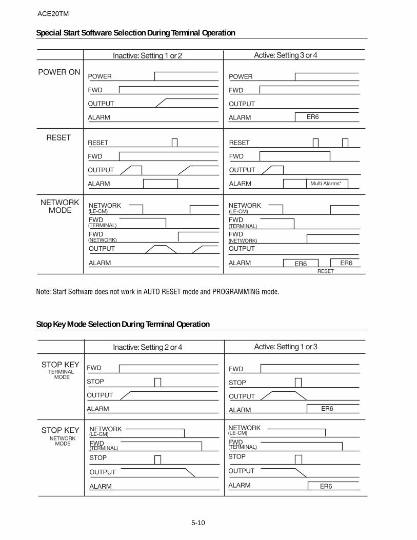
5-10
Special Start Software Selection During Terminal Operation
Stop Key Mode Selection During Terminal Operation
Note: Start Software does not work in AUTO RESET mode and PROGRAMMING mode.
POWER ON
RESET
NETWORKMODE
Inactive: Setting 1 or 2 Active: Setting 3 or 4
POWER
FWD
OUTPUT
ALARM
POWER
FWD
OUTPUT
ALARM
RESET
FWD
OUTPUT
ALARM
RESET
FWD
OUTPUT
ALARM
NETWORK
FWD
FWD
OUTPUT
ALARM
ER6
Multi Alarms*
(LE-CM)
(TERMINAL)
(NETWORK)
ER6 ER6RESET
NETWORK
FWD
FWD
OUTPUT
ALARM
(LE-CM)
(TERMINAL)
(NETWORK)
NETWORK
FWD
STOP
OUTPUT
ALARM
(LE-CM)
(TERMINAL)
NETWORK
FWD
STOP
OUTPUT
ALARM
(LE-CM)
(TERMINAL)
FWD
STOP
OUTPUT
ALARM
FWD
STOP
OUTPUT
ALARM
Inactive: Setting 2 or 4 Active: Setting 1 or 3
STOP KEY
STOP KEY
TERMINAL MODE
NETWORKMODE
ER6
ER6
ACE20TM
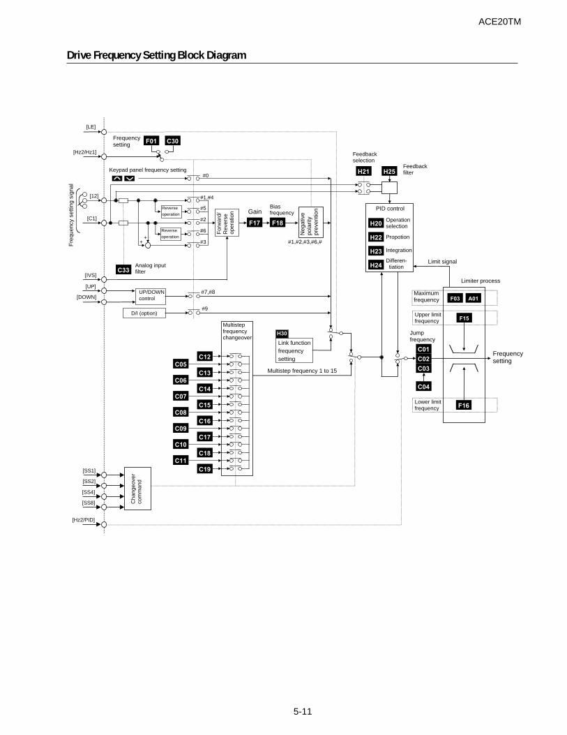
5-11
[LE]
H21
F18F17
C33
Keypad panel frequency setting
Frequencysetting
[Hz2/Hz1]
Reverse
operation
Reverse
operation
[12]
[C1]
[IVS]
[UP]
[DOWN]
[SS1]
[SS2]
Cha
ngeo
ver
com
man
d
[SS4]
[SS8]
[Hz2/PID]
Feedbackselection
Biasfrequency
++
#3
#6
#2
#5
#1,#4
#0
Gain
Link functionfrequencysetting
D/I (option)
UP/DOWNcontrol
Jumpfrequency
Multistep frequency 1 to 15
Fre
quen
cy s
ettin
g si
gnal
Analog inputfilter
Neg
ativ
epo
larit
ypr
even
tion
For
war
d/R
ever
seop
erat
ion
H25
Feedbackfilter
H22
Integration
Propotion
H23
H20
Operationselection
PID control
Differen- tiation
C04
C03
C01
C02
H24
Limit signal
Limiter process
A01
F15
F03
Frequencysetting
Upper limitfrequency
Maximumfrequency
Lower limitfrequency F16
#9
#1,#2,#3,#6,#7
#7,#8
H30
F01 C30
Multistepfrequencychangeover
C13
C05
C12
C14
C06
C15
C07
C16
C08
C17
C09
C18
C10
C19
C11
Drive Frequency Setting Block Diagram
ACE20TM

5-12
F03 Maximum output frequency 1
F 0 3
Setting range: 50 to 400 Hz
This function sets the maximum output frequency forMotor 1.
If a value larger than the rated maximum speed of themotor is set, the motor can be damaged.
F04 Base frequency 1
F 0 4
Setting range: 25 to 400 Hz
This sets the maximum output frequency in the con-stant torque range of Motor 1, or the output frequencyat the rated output voltage. Set it to match themotor rating.
Note: If the value of base frequency 1 is larger than thevalue of maximum frequency 1, the output frequency willbe limited by the maximum frequency, and the outputvoltage will not increase to the rated voltage.
Outputfrequency
F06 Maximum outputvoltage 1
Output
voltage
F05 Rated voltage 1
0 F04 Basefrequency 1
F03 Maximumoutput frequency
Constant torque
zone
F05 Rated voltage 1
F 0 5
Setting range: 0, 80 to 240 V for 230V class0, 160 to 480V for 460V class
This function sets the rated value of the output voltageof Motor 1. However, output voltage cannot exceed thesupply (input) voltage.
A “0” setting stops the operation of the voltage regula-tor function. Therefore, the output voltage is propor-tional to the supply voltage.
Note: If the value of the rated voltage is higher than thevalue of the maximum output voltage, the voltage will belimited by the maximum output voltage and will notincrease to the rated voltage.
F06 Maximum voltage 1
F 0 6
Setting range: 80 to 240 V for 230V class160 to 480V for 460V class
This function sets the maximum value of the outputvoltage for Motor 1. However, output voltage cannotexceed the supply (input) voltage.
F07 Acceleration time 1
F 0 7
F08 Deceleration time 1
F 0 8
Setting range: Acceleration time 1: 0.01 to 3600 sDeceleration time 1: 0.01 to 3600 s
These functions set the acceleration time taken for theoutput frequency to reach the maximum frequencyfrom the start command, and the deceleration timetaken to stop from the maximum output frequency.
The number of significant digits of the acceleration anddeceleration time is three. Therefore, only the upper-most three digits can be set.
The acceleration time and deceleration times are setbased on the maximum frequency. The relationshipbetween the frequency setting and the acceleration/deceleration time is as shown below.
Set frequency = max. frequencyThe actual operation time matches the set value.
Out
put f
requ
ency
Accelerationtime
Setfrequency
Time
Decelerationtime
Maximum
outputfrequency
FWD STOP
Set frequency < Maximum output frequency
The accel/decel times differ from the set value.
Acceleration/deceleration time = Set value x (Setfrequency / Maximum output frequency)
ACE20TM
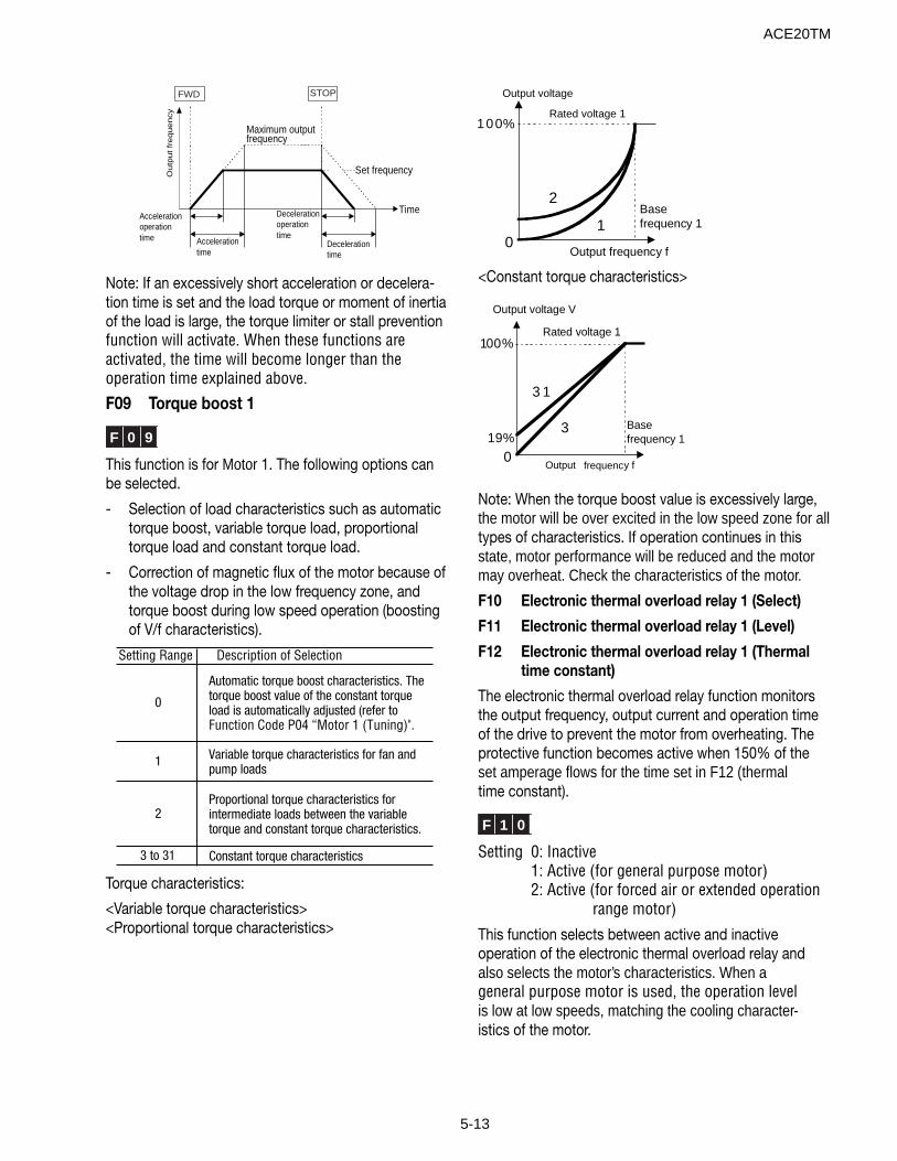
5-13
Accelerationoperationtime
Time
Set frequency
Decelerationtime
Accelerationtime
Decelerationoperationtime
Outp
ut fr
equency
Maximum outputfrequency
FWD STOP
Note: If an excessively short acceleration or decelera-tion time is set and the load torque or moment of inertiaof the load is large, the torque limiter or stall preventionfunction will activate. When these functions areactivated, the time will become longer than theoperation time explained above.
F09 Torque boost 1
F 0 9
This function is for Motor 1. The following options canbe selected.
- Selection of load characteristics such as automatictorque boost, variable torque load, proportionaltorque load and constant torque load.
- Correction of magnetic flux of the motor because ofthe voltage drop in the low frequency zone, andtorque boost during low speed operation (boostingof V/f characteristics).
Torque characteristics:
<Variable torque characteristics><Proportional torque characteristics>
100%
Output frequency f
Basefrequency 11
2
0
Rated voltage 1
Output voltage
<Constant torque characteristics>
100%
Output
frequency f
Basefrequency 1
3
3 1
019%
Rated voltage 1
Output voltage V
Note: When the torque boost value is excessively large,the motor will be over excited in the low speed zone for alltypes of characteristics. If operation continues in thisstate, motor performance will be reduced and the motormay overheat. Check the characteristics of the motor.
F10 Electronic thermal overload relay 1 (Select)
F11 Electronic thermal overload relay 1 (Level)
F12 Electronic thermal overload relay 1 (Thermaltime constant)
The electronic thermal overload relay function monitorsthe output frequency, output current and operation timeof the drive to prevent the motor from overheating. Theprotective function becomes active when 150% of theset amperage flows for the time set in F12 (thermaltime constant).
F 1 0
Setting 0: Inactive1: Active (for general purpose motor)2: Active (for forced air or extended operation
range motor)
This function selects between active and inactiveoperation of the electronic thermal overload relay andalso selects the motor’s characteristics. When ageneral purpose motor is used, the operation levelis low at low speeds, matching the cooling character-istics of the motor.
Setting Range Description of Selection
0
Automatic torque boost characteristics. The torque boost value of the constant torque load is automatically adjusted (refer to Function Code P04 “Motor 1 (Tuning)".
1 Variable torque characteristics for fan and pump loads
2Proportional torque characteristics for intermediate loads between the variable torque and constant torque characteristics.
3 to 31 Constant torque characteristics
ACE20TM
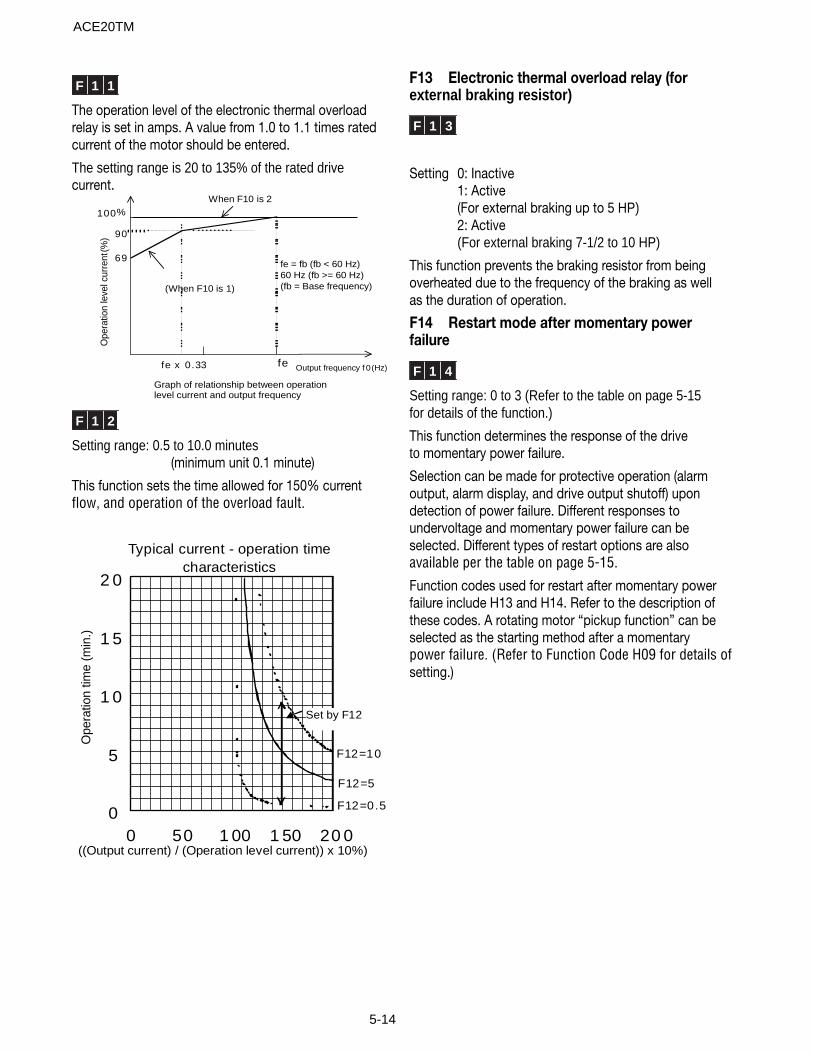
5-14
F13 Electronic thermal overload relay (forexternal braking resistor)
F 1 3
Setting 0: Inactive1: Active(For external braking up to 5 HP)2: Active(For external braking 7-1/2 to 10 HP)
This function prevents the braking resistor from beingoverheated due to the frequency of the braking as wellas the duration of operation.
F14 Restart mode after momentary powerfailure
F 1 4
Setting range: 0 to 3 (Refer to the table on page 5-15for details of the function.)
This function determines the response of the driveto momentary power failure.
Selection can be made for protective operation (alarmoutput, alarm display, and drive output shutoff) upondetection of power failure. Different responses toundervoltage and momentary power failure can beselected. Different types of restart options are alsoavailable per the table on page 5-15.
Function codes used for restart after momentary powerfailure include H13 and H14. Refer to the description ofthese codes. A rotating motor “pickup function” can beselected as the starting method after a momentarypower failure. (Refer to Function Code H09 for details ofsetting.)
F 1 1
The operation level of the electronic thermal overloadrelay is set in amps. A value from 1.0 to 1.1 times ratedcurrent of the motor should be entered.
The setting range is 20 to 135% of the rated drivecurrent.
Output frequency f 0 (Hz)
Ope
ratio
n le
vel c
urre
nt(%
)
fe x 0.33 fe
90
100
69
When F10 is 2%
(When F10 is 1)
Graph of relationship between operationlevel current and output frequency
fe = fb (fb < 60 Hz)60 Hz (fb >= 60 Hz)(fb = Base frequency)
F 1 2
Setting range: 0.5 to 10.0 minutes (minimum unit 0.1 minute)
This function sets the time allowed for 150% currentflow, and operation of the overload fault.
Typical current - operation timecharacteristics
0
5
1 0
1 5
2 0
0 50 1 00 1 50 20 0
Ope
ratio
n tim
e (m
in.)
F12=0.5
F12=10
F12=5
Set by F12
((Output current) / (Operation level current)) x 10%)
ACE20TM
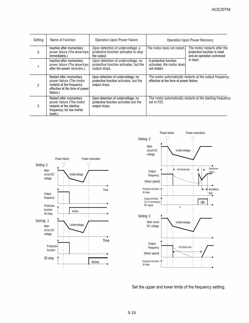
5-15
Setting: 0Maincircuit DCvoltage
Power failure
Undervoltage
Power restoration
TimeOutputfrequency
Active
Maincircuit
DCvoltage
Undervoltage
TimeProtectivefunction
Active
Sett ing: 1
Protectivefunction30 relay
30
relay
Setting: 2
Power failure Power restoration
Setting: 3
Accelera-tion
Undervoltage
Outputfrequency
H13:Wait time Synchroni-zation
(Motor speed)
Maincircuit DCvoltage
ONOutput terminal(Y1-Y2 terminals);IPF signal
Undervoltage
Outputfrequency H13:Wait time
Main
c
circuitDC voltage
Protective function30 relay
(Motor speed)
Protective function30 relay
Setting Name of Function Operation Upon Power Failure
0Inactive after momentary power failure (The drive trips immediately.)
Upon detection of undervoltage, a protective function activates to stop the output.
The motor does not restart.
1
Inactive after momentary power failure (The drive trips after the power recovers.)
Upon detection of undervoltage, no protective function activates, but the output stops.
A protective functionactivates; the motor does not restart.
2
Restart after momentary power failure (The motor restarts at the frequency effective at the time of power failure.)
Upon detection of undervoltage, no protective function activates, but the output stops.
3
Restart after momentary power failure (The motorrestarts at the starting frequency; for low inertia loads.)
Upon detection of undervoltage, no protective function activates but the output stops.
Operation Upon Power Recovery
The motor automatically restarts at the output frequency effective at the time of power failure.
The motor automatically restarts at the starting frequency set in F23.
The motor restarts after the protective function is reset and an operation command is input.
Set the upper and lower limits of the frequency setting.
ACE20TM
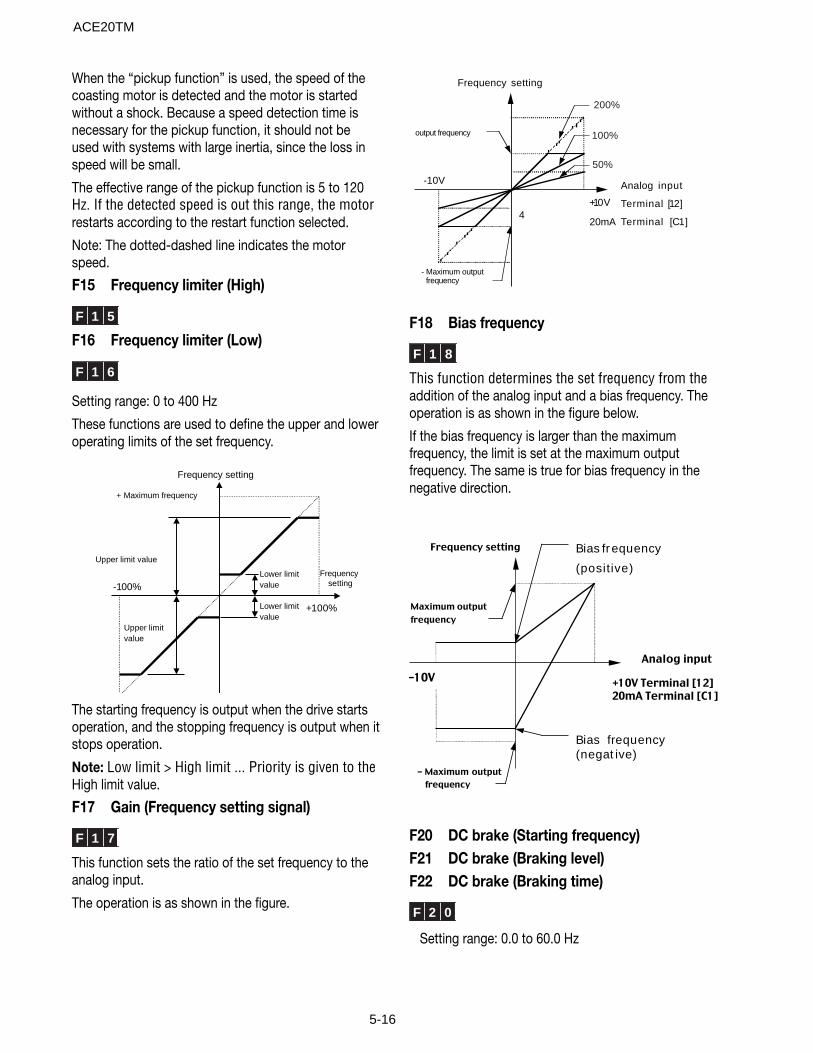
5-16
When the “pickup function” is used, the speed of thecoasting motor is detected and the motor is startedwithout a shock. Because a speed detection time isnecessary for the pickup function, it should not beused with systems with large inertia, since the loss inspeed will be small.
The effective range of the pickup function is 5 to 120Hz. If the detected speed is out this range, the motorrestarts according to the restart function selected.
Note: The dotted-dashed line indicates the motorspeed.
F15 Frequency limiter (High)
F 1 5
F16 Frequency limiter (Low)
F 1 6
Setting range: 0 to 400 Hz
These functions are used to define the upper and loweroperating limits of the set frequency.
Lower limitvalue
Lower limitvalue
Upper limit value
Upper limitvalue
Frequencysetting
Frequency
setting
+ Maximum frequency
+100%
-100%
The starting frequency is output when the drive startsoperation, and the stopping frequency is output when itstops operation.
Note: Low limit > High limit ... Priority is given to theHigh limit value.
F17 Gain (Frequency setting signal)
F 1 7
This function sets the ratio of the set frequency to theanalog input.
The operation is as shown in the figure.
4
-10V
+1 0 V
Frequency setting
Analog input
Terminal [1 2 ]
Terminal [ C 1 ]
output frequency
- Maximum outputfrequency
2 0 0 %
1 0 0 %
5 0 %
20mA
F18 Bias frequency
F 1 8
This function determines the set frequency from theaddition of the analog input and a bias frequency. Theoperation is as shown in the figure below.
If the bias frequency is larger than the maximumfrequency, the limit is set at the maximum outputfrequency. The same is true for bias frequency in thenegative direction.
-10V
Frequency setting
Analog input
+10V Terminal [12]
20mA Terminal [C1]
Bias fr equency
(positive)
Bias frequency(negat ive)
Maximum output
frequency
- Maximum output
frequency
F20 DC brake (Starting frequency)F21 DC brake (Braking level)F22 DC brake (Braking time)
F 2 0
Setting range: 0.0 to 60.0 Hz
ACE20TM
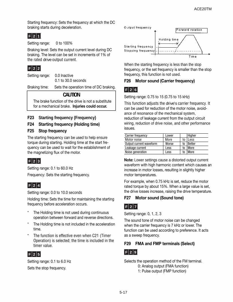
5-17
Starting frequency: Sets the frequency at which the DCbraking starts during deceleration.
F 2 1
Setting range: 0 to 100%
Braking level: Sets the output current level during DCbraking. The level can be set in increments of 1% ofthe rated drive output current.
F 2 2
Setting range: 0.0 Inactive0.1 to 30.0 seconds
Braking time: Sets the operation time of DC braking.
CAUTION The brake function of the drive is not a substitute for a mechanical brake. Injuries could occur.
F23 Starting frequency (Frequency)F24 Starting frequency (Holding time)F25 Stop frequencyThe starting frequency can be used to help ensuretorque during starting. Holding time at the start fre-quency can be used to wait for the establishment ofthe magnetizing flux of the motor.
F 2 3
Setting range: 0.1 to 60.0 Hz
Frequency: Sets the starting frequency.
F 2 4
Setting range: 0.0 to 10.0 seconds
Holding time: Sets the time for maintaining the startingfrequency before acceleration occurs.
* The Holding time is not used during continuousoperation between forward and reverse directions.
* The Holding time is not included in the accelerationtime.
* The function is effective even when C21 (TimerOperation) is selected; the time is included in thetimer value.
F 2 5
Setting range: 0.1 to 6.0 Hz
Sets the stop frequency.
When the starting frequency is less than the stopfrequency, or the set frequency is smaller than the stopfrequency, this function is not used.
F26 Motor sound (Carrier frequency)
F 2 6
Setting range: 0.75 to 15 (0.75 to 15 kHz)
This function adjusts the drive's carrier frequency. Itcan be used for reduction of the motor noise, avoid-ance of resonance of the mechanical system,reduction of leakage current from the output circuitwiring, reduction of drive noise, and other performanceissues.
Carrier frequency Lower HigherMotor noise More to LessOutput current waveform Worse to BetterLeakage current Less to MoreNoise generation Less to More
Note: Lower settings cause a distorted output currentwaveform with high harmonic content which causes anincrease in motor losses, resulting in slightly highermotor temperatures.
For example, when 0.75 kHz is set, reduce the motorrated torque by about 15%. When a large value is set,the drive losses increase, raising the drive temperature.
F27 Motor sound (Sound tone)
F 2 7
Setting range: 0, 1, 2, 3
The sound tone of motor noise can be changedwhen the carrier frequency is 7 kHz or lower. Thefunction can be used according to preference. It actsas a sweep frequency.
F29 FMA and FMP terminals (Select)
F 2 9
Selects the operation method of the FM terminal.0: Analog output (FMA function)1: Pulse output (FMP function)
ACE20TM
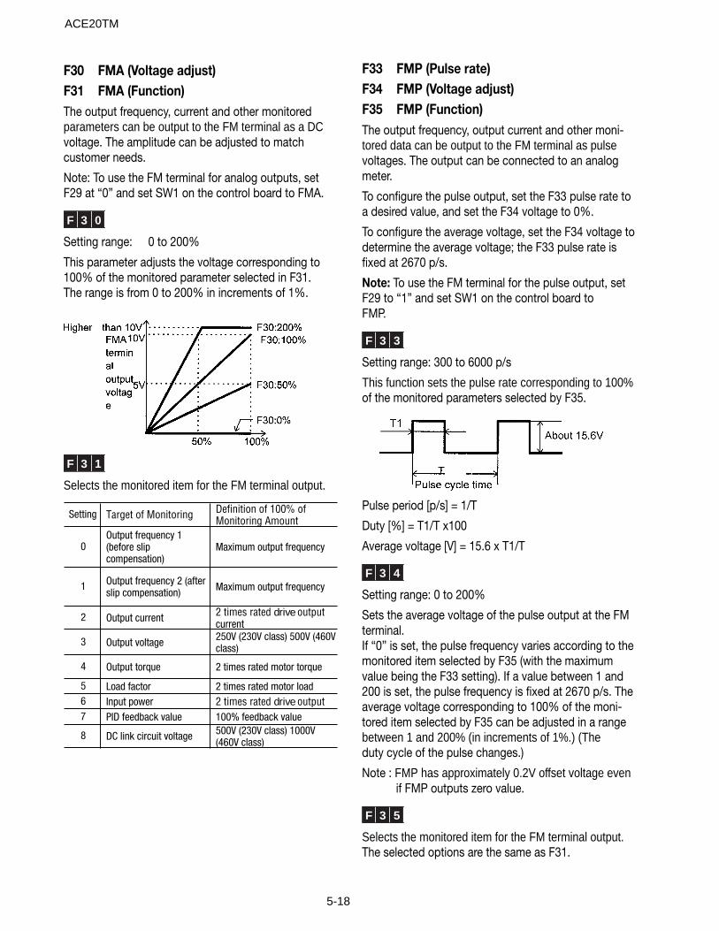
5-18
F30 FMA (Voltage adjust)F31 FMA (Function)The output frequency, current and other monitoredparameters can be output to the FM terminal as a DCvoltage. The amplitude can be adjusted to matchcustomer needs.
Note: To use the FM terminal for analog outputs, setF29 at “0” and set SW1 on the control board to FMA.
F 3 0
Setting range: 0 to 200%
This parameter adjusts the voltage corresponding to100% of the monitored parameter selected in F31.The range is from 0 to 200% in increments of 1%.
F 3 1
Selects the monitored item for the FM terminal output.
Setting Target of Monitoring Definition of 100% of Monitoring Amount
0Output frequency 1 (before slip compensation)
Maximum output frequency
1 Output frequency 2 (after slip compensation) Maximum output frequency
2 Output current 2 times rated drive outputcurrent
3 Output voltage 250V (230V class) 500V (460V class)
4 Output torque 2 times rated motor torque
5 Load factor 2 times rated motor load6 Input power 2 times rated drive output7 PID feedback value 100% feedback value
8 DC link circuit voltage 500V (230V class) 1000V (460V class)
F33 FMP (Pulse rate)F34 FMP (Voltage adjust)F35 FMP (Function)The output frequency, output current and other moni-tored data can be output to the FM terminal as pulsevoltages. The output can be connected to an analogmeter.
To configure the pulse output, set the F33 pulse rate toa desired value, and set the F34 voltage to 0%.
To configure the average voltage, set the F34 voltage todetermine the average voltage; the F33 pulse rate isfixed at 2670 p/s.
Note: To use the FM terminal for the pulse output, setF29 to “1” and set SW1 on the control board toFMP.
F 3 3
Setting range: 300 to 6000 p/s
This function sets the pulse rate corresponding to 100%of the monitored parameters selected by F35.
Pulse period [p/s] = 1/T
Duty [%] = T1/T x100
Average voltage [V] = 15.6 x T1/T
F 3 4
Setting range: 0 to 200%
Sets the average voltage of the pulse output at the FMterminal.If “0” is set, the pulse frequency varies according to themonitored item selected by F35 (with the maximumvalue being the F33 setting). If a value between 1 and200 is set, the pulse frequency is fixed at 2670 p/s. Theaverage voltage corresponding to 100% of the moni-tored item selected by F35 can be adjusted in a rangebetween 1 and 200% (in increments of 1%.) (Theduty cycle of the pulse changes.)
Note : FMP has approximately 0.2V offset voltage even if FMP outputs zero value.
F 3 5
Selects the monitored item for the FM terminal output.The selected options are the same as F31.
ACE20TM
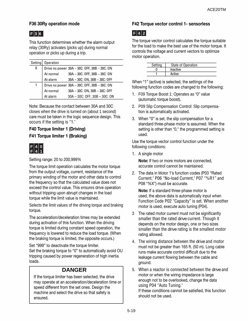
5-19
F36 30Ry operation mode
F 3 6
This function determines whether the alarm outputrelay (30Ry) activates (picks up) during normaloperation or picks up during a trip.
Setting Operation0 Drive no power 30A – 30C: OFF, 30B – 30C: ON
At normal 30A – 30C: OFF, 30B – 30C: ONAt alarm 30A – 30C: ON, 30B – 30C: OFF
1 Drive no power 30A – 30C: OFF, 30B – 30C: ONAt normal 30A – 30C: ON, 30B – 30C: OFFAt alarm 30A – 30C: OFF, 30B – 30C: ON
Note: Because the contact between 30A and 30C closes when the drive is turned on (about 1 second)care must be taken in the logic sequence design. Thisoccurs if the setting is “1."
F40 Torque limiter 1 (Driving)F41 Torque limiter 1 (Braking)
F 4 0F 4 1
Setting range: 20 to 200,999%
The torque limit operation calculates the motor torquefrom the output voltage, current, resistance of theprimary winding of the motor and other data to controlthe frequency so that the calculated value does notexceed the control value. This ensures drive operationwithout tripping upon abrupt changes in the loadtorque while the limit value is maintained.
Selects the limit values of the driving torque and brakingtorque.
The acceleration/deceleration times may be extendedduring activation of this function. When the drivingtorque is limited during constant speed operation, thefrequency is lowered to reduce the load torque. (Whenthe braking torque is limited, the opposite occurs.)
Set “999” to deactivate the torque limiter.Set the braking torque to “0” to automatically avoid OUtripping caused by power regeneration of high inertialoads.
DANGERIf the torque limiter has been selected, the drivemay operate at an acceleration/deceleration time orspeed different from the set ones. Design themachine and select the drive so that safety isensured.
F42 Torque vector control 1- sensorless
F 4 2
The torque vector control calculates the torque suitablefor the load to make the best use of the motor torque. Itcontrols the voltage and current vectors to optimizemotor operation.
Setting State of Operation0 Inactive1 Active
When “1” (active) is selected, the settings of thefollowing function codes are changed to the following:
1. F09 Torque Boost 1: Operates as “0” value(automatic torque boost).
2. P09 Slip Compensation Control: Slip compensa-tion is automatically activated.
3. When “0” is set, the slip compensation for astandard three-phase motor is assumed. When thesetting is other than “0," the programmed setting isused.
Use the torque vector control function under thefollowing conditions:
1. A single motor
Note: If two or more motors are connected,accurate control cannot be maintained.
2. The data in Motor 1’s function codes (P03 “RatedCurrent," P06 “No-load Current," P07 “%R1” andP08 “%X”) must be accurate.
Note: If a standard three-phase motor isused, the above data is automatically input whenFunction Code P02 “Capacity” is set. When anothermotor is used, execute auto tuning (P04).
3 The rated motor current must not be significantlysmaller than the rated drive current. Though itdepends on the motor design, one or two sizessmaller than the drive rating is the smallest motorrating allowed.
4. The wiring distance between the drive and motormust not be greater than 165 ft. (50 m). Long cableruns make accurate control difficult due to theleakage current flowing between the cable andground.
5. When a reactor is connected between the drive andmotor or when the wiring impedance is largeenough not to be overlooked, change the datausing P04 “Auto Tuning."If these conditions cannot be satisfied, this functionshould not be used.
ACE20TM
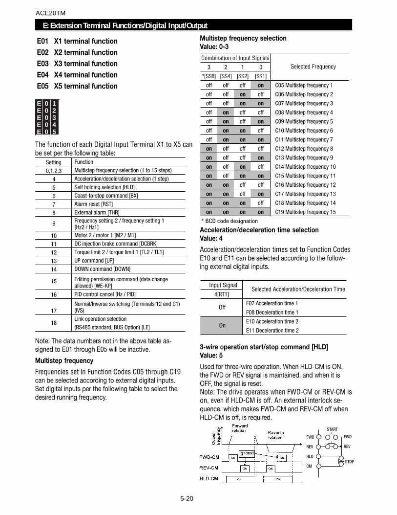
5-20
E01 X1 terminal function E02 X2 terminal function E03 X3 terminal function E04 X4 terminal function E05 X5 terminal function
E 0 1E 0 2E 0 3E 0 4E 0 5
The function of each Digital Input Terminal X1 to X5 canbe set per the following table:
Setting Function
0,1,2,3 Multistep frequency selection (1 to 15 steps)
4 Acceleration/deceleration selection (1 step)
5 Self holding selection [HLD]
6 Coast-to-stop command [BX]
7 Alarm reset [RST]
8 External alarm [THR]
9 Frequency setting 2 / frequency setting 1 [Hz2 / Hz1]
10 Motor 2 / motor 1 [M2 / M1]
11 DC injection brake command [DCBRK]
12 Torque limit 2 / torque limit 1 [TL2 / TL1]
13 UP command [UP]
14 DOWN command [DOWN]
15 Editing permission command (data change allowed) [WE-KP]
16 PID control cancel [Hz / PID]
17Normal/Inverse switching (Terminals 12 and C1) (IVS)Link operation selection (RS485 standard, BUS Option) [LE]
18
Note: The data numbers not in the above table as-signed to E01 through E05 will be inactive.
Multistep frequency
Frequencies set in Function Codes C05 through C19can be selected according to external digital inputs.Set digital inputs per the following table to select thedesired running frequency.
Multistep frequency selectionValue: 0-3
Combination of Input Signals3 2 1 0
*[SS8] [SS4] [SS2] [SS1]
off off off on C05 Multistep frequency 1
off off on off C06 Multistep frequency 2
off off on on C07 Multistep frequency 3
off on off off C08 Multistep frequency 4
off on off on C09 Multistep frequency 5
off on on off C10 Multistep frequency 6
off on on on C11 Multistep frequency 7
on off off off C12 Multistep frequency 8
on off off on C13 Multistep frequency 9
on off on off C14 Multistep frequency 10
on off on on C15 Multistep frequency 11
on on off off C16 Multistep frequency 12
on on off on C17 Multistep frequency 13
on on on off C18 Multistep frequency 14
on on on on C19 Multistep frequency 15
* BCD code designation
Selected Frequency
Acceleration/deceleration time selectionValue: 4
Acceleration/deceleration times set to Function CodesE10 and E11 can be selected according to the follow-ing external digital inputs.
Input Signal4[RT1]
F07 Acceleration time 1
F08 Deceleration time 1
E10 Acceleration time 2
E11 Deceleration time 2
Off
On
Selected Acceleration/Deceleration Time
3-wire operation start/stop command [HLD]Value: 5
Used for three-wire operation. When HLD-CM is ON,the FWD or REV signal is maintained, and when it isOFF, the signal is reset.Note: The drive operates when FWD-CM or REV-CM ison, even if HLD-CM is off. An external interlock se-quence, which makes FWD-CM and REV-CM off whenHLD-CM is off, is required.
FWD
REV
HLD
CM
FWD
REV
STOP
START
E: Extension Terminal Functions/Digital Input/Output
ACE20TM
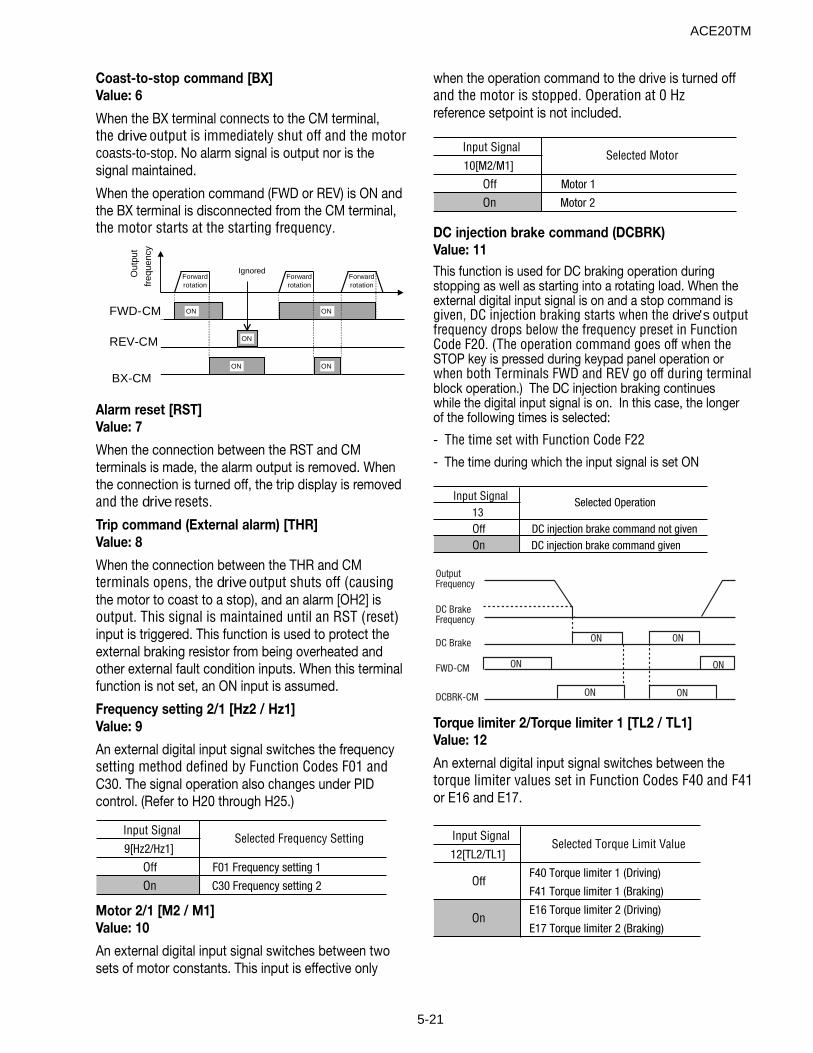
5-21
Coast-to-stop command [BX]Value: 6
When the BX terminal connects to the CM terminal,the drive output is immediately shut off and the motorcoasts-to-stop. No alarm signal is output nor is thesignal maintained.
When the operation command (FWD or REV) is ON andthe BX terminal is disconnected from the CM terminal,the motor starts at the starting frequency.
Forwardrotation
ON
ONON
ONONFWD-CM
REV-CM
BX-CM
Out
put
freq
uenc
y
IgnoredForwardrotation
Forwardrotation
Alarm reset [RST]Value: 7
When the connection between the RST and CMterminals is made, the alarm output is removed. Whenthe connection is turned off, the trip display is removedand the drive resets.
Trip command (External alarm) [THR]Value: 8
When the connection between the THR and CMterminals opens, the drive output shuts off (causingthe motor to coast to a stop), and an alarm [OH2] isoutput. This signal is maintained until an RST (reset)input is triggered. This function is used to protect theexternal braking resistor from being overheated andother external fault condition inputs. When this terminalfunction is not set, an ON input is assumed.
Frequency setting 2/1 [Hz2 / Hz1]Value: 9
An external digital input signal switches the frequencysetting method defined by Function Codes F01 andC30. The signal operation also changes under PIDcontrol. (Refer to H20 through H25.)
Input Signal9[Hz2/Hz1]
Off F01 Frequency setting 1
On C30 Frequency setting 2
Selected Frequency Setting
Motor 2/1 [M2 / M1]Value: 10
An external digital input signal switches between twosets of motor constants. This input is effective only
when the operation command to the drive is turned offand the motor is stopped. Operation at 0 Hzreference setpoint is not included.
Input Signal10[M2/M1]
Off Motor 1
On Motor 2
Selected Motor
DC injection brake command (DCBRK)Value: 11This function is used for DC braking operation duringstopping as well as starting into a rotating load. When theexternal digital input signal is on and a stop command isgiven, DC injection braking starts when the drive's outputfrequency drops below the frequency preset in FunctionCode F20. (The operation command goes off when theSTOP key is pressed during keypad panel operation orwhen both Terminals FWD and REV go off during terminalblock operation.) The DC injection braking continueswhile the digital input signal is on. In this case, the longerof the following times is selected:
- The time set with Function Code F22
- The time during which the input signal is set ON
Input Signal13Off DC injection brake command not givenOn DC injection brake command given
Selected Operation
Torque limiter 2/Torque limiter 1 [TL2 / TL1]Value: 12
An external digital input signal switches between thetorque limiter values set in Function Codes F40 and F41or E16 and E17.
Input Signal12[TL2/TL1]
F40 Torque limiter 1 (Driving)
F41 Torque limiter 1 (Braking)
E16 Torque limiter 2 (Driving)
E17 Torque limiter 2 (Braking)
Selected Torque Limit Value
On
Off
OutputFrequency
DC BrakeFrequency
DC Brake
FWD-CM
DCBRK-CM
ON
ON ON
ON
ON ON
ACE20TM
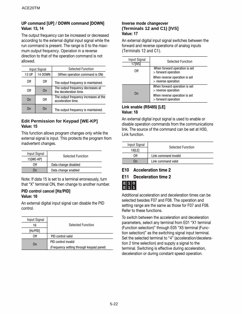
5-22
Selected Function13 UP 14 DOWN (When operation command is ON)
Off Off The output frequency is maintained.
Off OnThe output frequency decreases at the deceleration time.
On OffThe output frequency increases at the acceleration time.
On On The output frequency is maintained.
Input Signal
Edit Permission for Keypad [WE-KP]Value: 15
This function allows program changes only while theexternal signal is input. This protects the program frominadvertent changes.
Input Signal15[WE-KP]
Off Data change disabled
On Data change enabled
Selected Function
Note: If data 15 is set to a terminal erroneously, turnthat “X” terminal ON, then change to another number.
PID control cancel [Hz/PID]Value: 16
An external digital input signal can disable the PIDcontrol.
Input Signal16
[Hz/PID]
Off PID control valid
PID control invalid
(Frequency setting through keypad panel)
Selected Function
On
Inverse mode changeover(Terminals 12 and C1) [IVS]Value: 17
An external digital input signal switches between theforward and reverse operations of analog inputs(Terminals 12 and C1).
Input Signal17[IVS]
OffWhen forward operation is set > forward operationWhen reverse operation is set > reverse operationWhen forward operation is set > reverse operationWhen reverse operation is set > forward operation
Selected Function
On
Link enable (RS485) [LE]Value: 18
An external digital input signal is used to enable ordisable operation commands from the communicationslink. The source of the command can be set at H30,Link function.
Input Signal18[LE]
Off Link command invalid
On Link command valid
Selected Function
E10 Acceleration time 2E11 Deceleration time 2E 1 0E 1 1
Additional acceleration and deceleration times can beselected besides F07 and F08. The operation andsetting range are the same as those for F07 and F08.Refer to these functions.
To switch between the acceleration and decelerationparameters, select any terminal from E01 “X1 terminal(Function selection)” through E05 “X5 terminal (Func-tion selection)” as the switching signal input terminal.Set the selected terminal to “4” (acceleration/decelera-tion 2 time selection) and supply a signal to theterminal. Switching is effective during acceleration,deceleration or during constant speed operation.
UP command [UP] / DOWN command [DOWN]Value: 13, 14
The output frequency can be increased or decreasedaccording to the external digital input signal while therun command is present. The range is 0 to the maxi-mum output frequency. Operation in a reversedirection to that of the operation command is notallowed.
ACE20TM
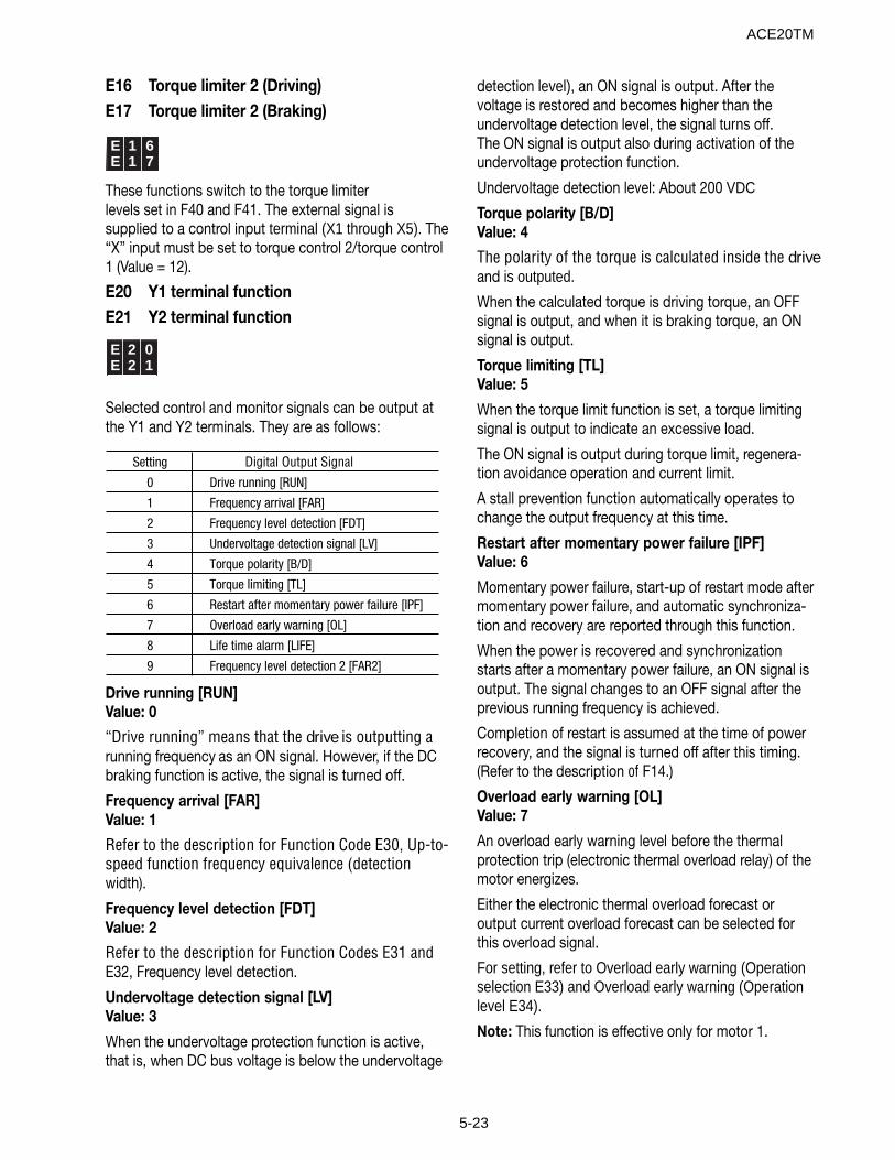
5-23
E16 Torque limiter 2 (Driving)E17 Torque limiter 2 (Braking)
E 1 6E 1 7
These functions switch to the torque limiterlevels set in F40 and F41. The external signal issupplied to a control input terminal (X1 through X5). The“X” input must be set to torque control 2/torque control1 (Value = 12).
E20 Y1 terminal functionE21 Y2 terminal function
E 2 0E 2 1
Selected control and monitor signals can be output atthe Y1 and Y2 terminals. They are as follows:
Setting Digital Output Signal0 Drive running [RUN]
1 Frequency arrival [FAR]
2 Frequency level detection [FDT]
3 Undervoltage detection signal [LV]
4 Torque polarity [B/D]
5 Torque limiting [TL]
6 Restart after momentary power failure [IPF]
7 Overload early warning [OL]
8 Life time alarm [LIFE]
9 Frequency level detection 2 [FAR2]
Drive running [RUN]Value: 0
“Drive running” means that the drive is outputting arunning frequency as an ON signal. However, if the DCbraking function is active, the signal is turned off.
Frequency arrival [FAR]Value: 1
Refer to the description for Function Code E30, Up-to-speed function frequency equivalence (detectionwidth).
Frequency level detection [FDT]Value: 2
Refer to the description for Function Codes E31 andE32, Frequency level detection.
Undervoltage detection signal [LV]Value: 3
When the undervoltage protection function is active,that is, when DC bus voltage is below the undervoltage
detection level), an ON signal is output. After thevoltage is restored and becomes higher than theundervoltage detection level, the signal turns off.The ON signal is output also during activation of theundervoltage protection function.
Undervoltage detection level: About 200 VDC
Torque polarity [B/D]Value: 4
The polarity of the torque is calculated inside the driveand is outputed.
When the calculated torque is driving torque, an OFFsignal is output, and when it is braking torque, an ONsignal is output.
Torque limiting [TL]Value: 5
When the torque limit function is set, a torque limitingsignal is output to indicate an excessive load.
The ON signal is output during torque limit, regenera-tion avoidance operation and current limit.
A stall prevention function automatically operates tochange the output frequency at this time.
Restart after momentary power failure [IPF]Value: 6
Momentary power failure, start-up of restart mode aftermomentary power failure, and automatic synchroniza-tion and recovery are reported through this function.
When the power is recovered and synchronizationstarts after a momentary power failure, an ON signal isoutput. The signal changes to an OFF signal after theprevious running frequency is achieved.
Completion of restart is assumed at the time of powerrecovery, and the signal is turned off after this timing.(Refer to the description of F14.)
Overload early warning [OL]Value: 7
An overload early warning level before the thermalprotection trip (electronic thermal overload relay) of themotor energizes.
Either the electronic thermal overload forecast oroutput current overload forecast can be selected forthis overload signal.
For setting, refer to Overload early warning (Operationselection E33) and Overload early warning (Operationlevel E34).
Note: This function is effective only for motor 1.
ACE20TM
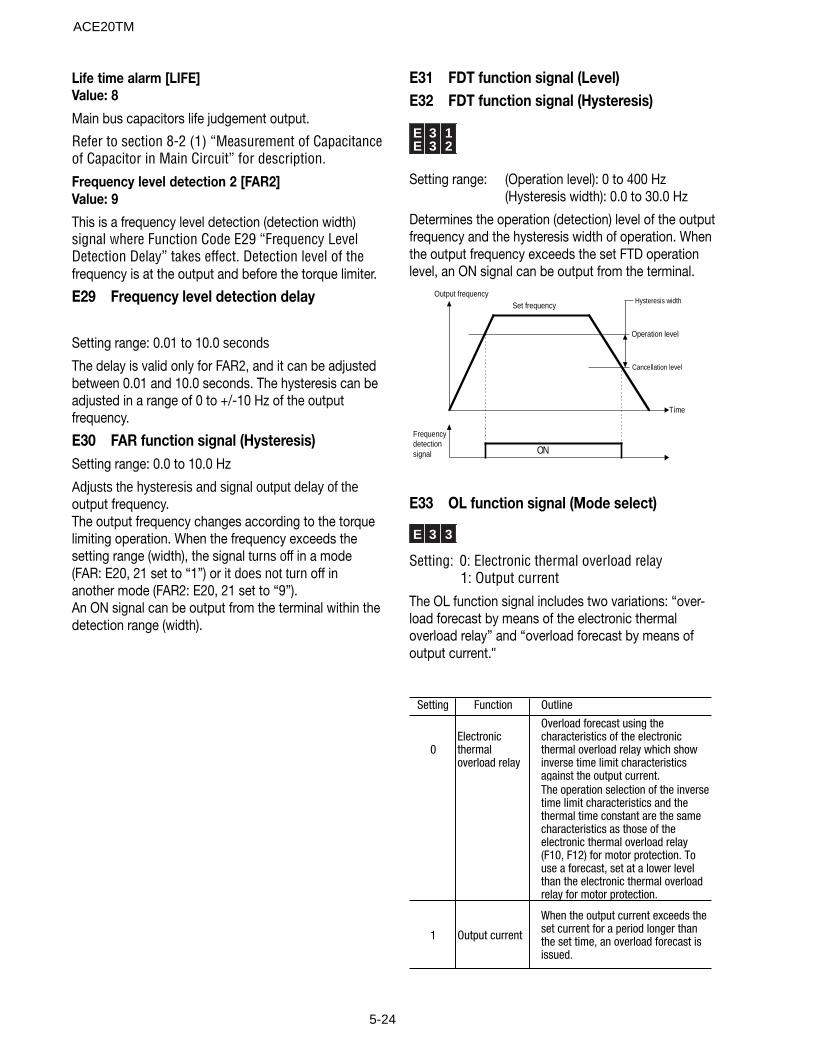
5-24
Life time alarm [LIFE]Value: 8
Main bus capacitors life judgement output.
Refer to section 8-2 (1) “Measurement of Capacitanceof Capacitor in Main Circuit” for description.
Frequency level detection 2 [FAR2]Value: 9
This is a frequency level detection (detection width)signal where Function Code E29 “Frequency LevelDetection Delay” takes effect. Detection level of thefrequency is at the output and before the torque limiter.
E29 Frequency level detection delay
Setting range: 0.01 to 10.0 seconds
The delay is valid only for FAR2, and it can be adjustedbetween 0.01 and 10.0 seconds. The hysteresis can beadjusted in a range of 0 to +/-10 Hz of the outputfrequency.
E30 FAR function signal (Hysteresis)Setting range: 0.0 to 10.0 Hz
Adjusts the hysteresis and signal output delay of theoutput frequency.The output frequency changes according to the torquelimiting operation. When the frequency exceeds thesetting range (width), the signal turns off in a mode(FAR: E20, 21 set to “1”) or it does not turn off inanother mode (FAR2: E20, 21 set to “9”).An ON signal can be output from the terminal within thedetection range (width).
E31 FDT function signal (Level)E32 FDT function signal (Hysteresis)
E 3 1E 3 2
Setting range: (Operation level): 0 to 400 Hz(Hysteresis width): 0.0 to 30.0 Hz
Determines the operation (detection) level of the outputfrequency and the hysteresis width of operation. Whenthe output frequency exceeds the set FTD operationlevel, an ON signal can be output from the terminal.
Output frequency
Frequencydetectionsignal
Hysteresis width
Operation level
Cancellation level
Time
ON
Set frequency
E33 OL function signal (Mode select)
E 3 3
Setting: 0: Electronic thermal overload relay1: Output current
The OL function signal includes two variations: “over-load forecast by means of the electronic thermaloverload relay” and “overload forecast by means ofoutput current."
Setting Function Outline
0Electronic thermal overload relay
Overload forecast using the characteristics of the electronic thermal overload relay which show inverse time limit characteristics against the output current.The operation selection of the inverse time limit characteristics and the thermal time constant are the same characteristics as those of the electronic thermal overload relay (F10, F12) for motor protection. To use a forecast, set at a lower level than the electronic thermal overload relay for motor protection.
1 Output current
When the output current exceeds the set current for a period longer than the set time, an overload forecast is issued.
ACE20TM
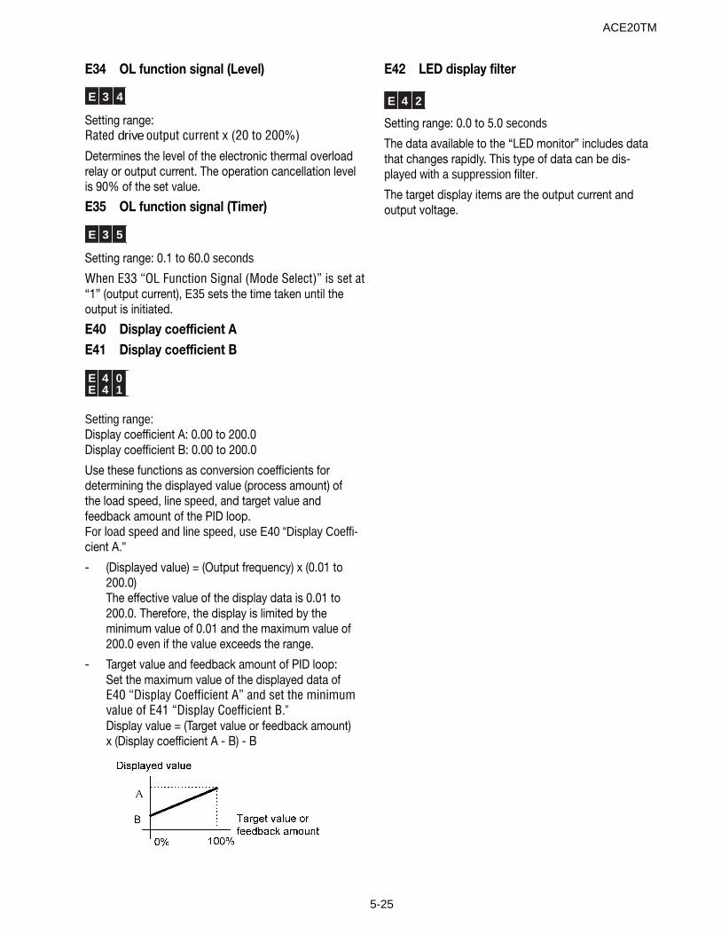
5-25
E42 LED display filter
E 4 2
Setting range: 0.0 to 5.0 seconds
The data available to the “LED monitor” includes datathat changes rapidly. This type of data can be dis-played with a suppression filter.
The target display items are the output current andoutput voltage.
E34 OL function signal (Level)
E 3 4
Setting range:Rated drive output current x (20 to 200%)
Determines the level of the electronic thermal overloadrelay or output current. The operation cancellation levelis 90% of the set value.
E35 OL function signal (Timer)
E 3 5
Setting range: 0.1 to 60.0 seconds
When E33 “OL Function Signal (Mode Select)” is set at“1” (output current), E35 sets the time taken until theoutput is initiated.
E40 Display coefficient AE41 Display coefficient B
E 4 0E 4 1
Setting range:Display coefficient A: 0.00 to 200.0Display coefficient B: 0.00 to 200.0
Use these functions as conversion coefficients fordetermining the displayed value (process amount) ofthe load speed, line speed, and target value andfeedback amount of the PID loop.For load speed and line speed, use E40 “Display Coeffi-cient A."
- (Displayed value) = (Output frequency) x (0.01 to200.0)The effective value of the display data is 0.01 to200.0. Therefore, the display is limited by theminimum value of 0.01 and the maximum value of200.0 even if the value exceeds the range.
- Target value and feedback amount of PID loop:Set the maximum value of the displayed data ofE40 “Display Coefficient A” and set the minimumvalue of E41 “Display Coefficient B."Display value = (Target value or feedback amount)x (Display coefficient A - B) - B
ACE20TM
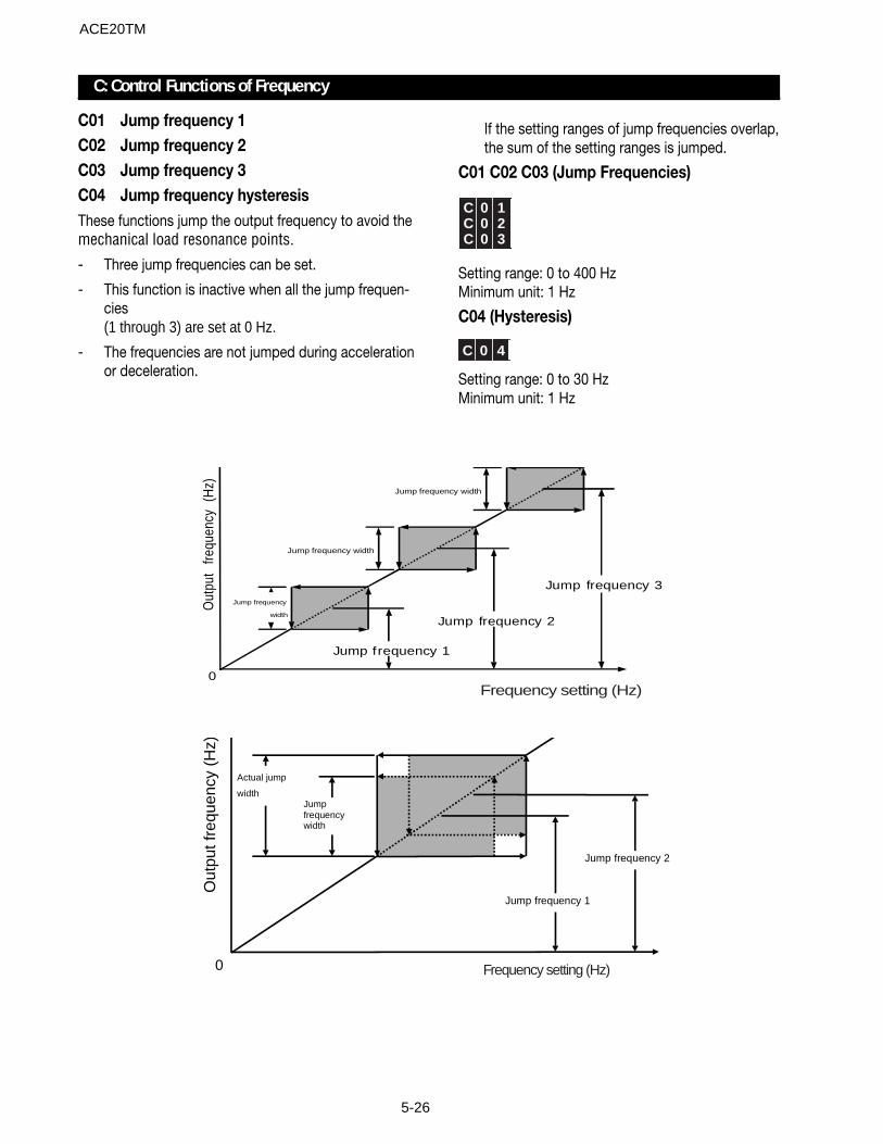
5-26
Jump frequency
width
Jump frequency 1
Jump frequency width
Jump frequency 2
Jump frequency width
Jump frequency 3
Out
put
frequ
ency
(H
z)
0Frequency setting (Hz)
Jumpfrequencywidth
Out
put f
requ
ency
(H
z)
Actual jump
width
Jump frequency 1
Jump frequency 2
0 Frequency setting (Hz)
C: Control Functions of Frequency
C01 Jump frequency 1C02 Jump frequency 2C03 Jump frequency 3C04 Jump frequency hysteresisThese functions jump the output frequency to avoid themechanical load resonance points.
- Three jump frequencies can be set.
- This function is inactive when all the jump frequen-cies(1 through 3) are set at 0 Hz.
- The frequencies are not jumped during accelerationor deceleration.
If the setting ranges of jump frequencies overlap,the sum of the setting ranges is jumped.
C01 C02 C03 (Jump Frequencies)
C 0 1C 0 2C 0 3
Setting range: 0 to 400 HzMinimum unit: 1 Hz
C04 (Hysteresis)
C 0 4
Setting range: 0 to 30 HzMinimum unit: 1 Hz
ACE20TM
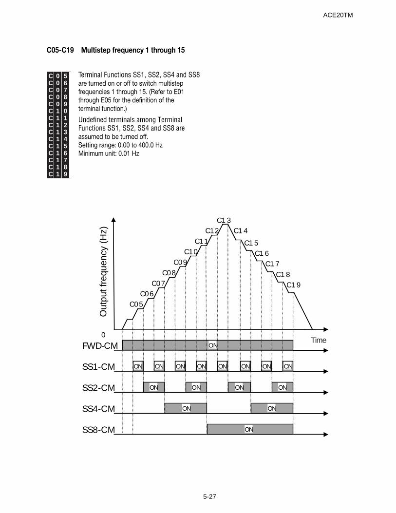
5-27
C05-C19 Multistep frequency 1 through 15
C 0 5C 0 6C 0 7C 0 8C 0 9C 1 0C 1 1C 1 2C 1 3C 1 4C 1 5C 1 6C 1 7C 1 8C 1 9
ON ON ON ON ON ON ON ON
ON
ON ON ON ON
ON ON
ON
C05
Out
put f
requ
ency
(H
z)
FWD-CM
SS1-CM
SS2-CM
SS4-CM
SS8-CM
C06C07
C08C09
C10C11
C12C1 3
C1 4
C1 5C1 6
C1 7
C1 8C1 9
0Time
Terminal Functions SS1, SS2, SS4 and SS8are turned on or off to switch multistepfrequencies 1 through 15. (Refer to E01through E05 for the definition of theterminal function.)
Undefined terminals among TerminalFunctions SS1, SS2, SS4 and SS8 areassumed to be turned off.Setting range: 0.00 to 400.0 HzMinimum unit: 0.01 Hz
ACE20TM
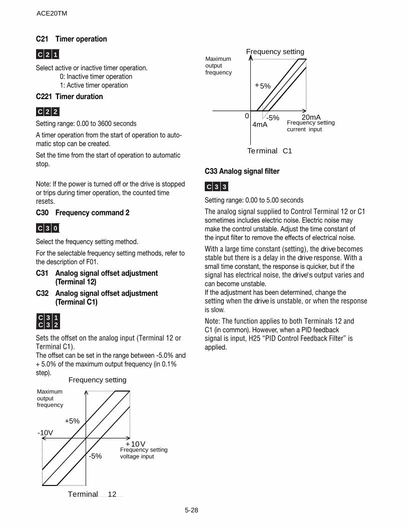
5-28
C21 Timer operation
C 2 1
Select active or inactive timer operation.0: Inactive timer operation1: Active timer operation
C221 Timer duration
C 2 2
Setting range: 0.00 to 3600 seconds
A timer operation from the start of operation to auto-matic stop can be created.
Set the time from the start of operation to automaticstop.
Note: If the power is turned off or the drive is stoppedor trips during timer operation, the counted timeresets.
C30 Frequency command 2
C 3 0
Select the frequency setting method.
For the selectable frequency setting methods, refer tothe description of F01.
C31 Analog signal offset adjustment(Terminal 12)
C32 Analog signal offset adjustment(Terminal C1)
C 3 1C 3 2
Sets the offset on the analog input (Terminal 12 orTerminal C1).The offset can be set in the range between -5.0% and+ 5.0% of the maximum output frequency (in 0.1%step).
Frequency setting
Maximumoutputfrequency
Frequency settingvoltage
input
Terminal 12
+5%
-5%
-10V
+10V
Maximumoutputfrequency
Frequency settingcurrent
input
Frequency setting
Terminal C1
+5%
04mA
20mA-5%
C33 Analog signal filter
C 3 3
Setting range: 0.00 to 5.00 seconds
The analog signal supplied to Control Terminal 12 or C1sometimes includes electric noise. Electric noise maymake the control unstable. Adjust the time constant ofthe input filter to remove the effects of electrical noise.
With a large time constant (setting), the drive becomesstable but there is a delay in the drive response. With asmall time constant, the response is quicker, but if thesignal has electrical noise, the drive's output varies andcan become unstable.If the adjustment has been determined, change thesetting when the drive is unstable, or when the responseis slow.
Note: The function applies to both Terminals 12 andC1 (in common). However, when a PID feedbacksignal is input, H25 “PID Control Feedback Filter” isapplied.
ACE20TM
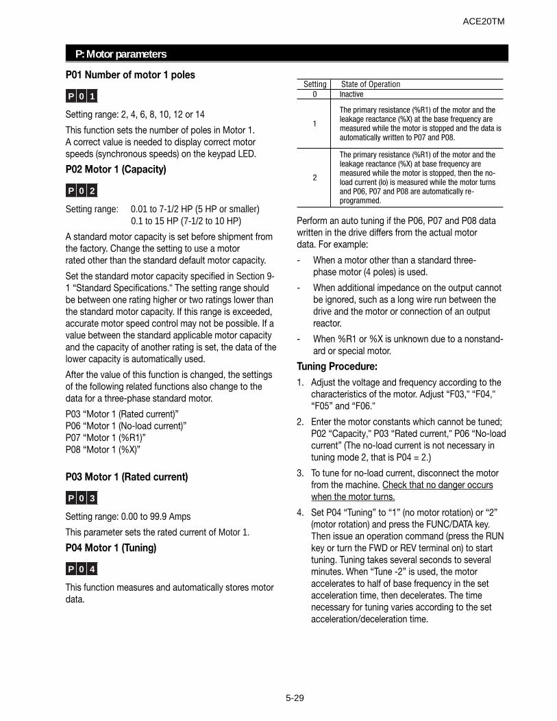
5-29
P: Motor parameters
Setting State of Operation0 Inactive
1
The primary resistance (%R1) of the motor and the leakage reactance (%X) at the base frequency are measured while the motor is stopped and the data is automatically written to P07 and P08.
2
The primary resistance (%R1) of the motor and the leakage reactance (%X) at base frequency are measured while the motor is stopped, then the no-load current (Io) is measured while the motor turns and P06, P07 and P08 are automatically re-programmed.
Perform an auto tuning if the P06, P07 and P08 datawritten in the drive differs from the actual motordata. For example:
- When a motor other than a standard three-phase motor (4 poles) is used.
- When additional impedance on the output cannotbe ignored, such as a long wire run between thedrive and the motor or connection of an outputreactor.
- When %R1 or %X is unknown due to a nonstand-ard or special motor.
Tuning Procedure:1. Adjust the voltage and frequency according to the
characteristics of the motor. Adjust “F03," “F04,"“F05” and “F06."
2. Enter the motor constants which cannot be tuned;P02 “Capacity," P03 “Rated current," P06 “No-loadcurrent” (The no-load current is not necessary intuning mode 2, that is P04 = 2.)
3. To tune for no-load current, disconnect the motorfrom the machine. Check that no danger occurswhen the motor turns.
4. Set P04 “Tuning” to “1” (no motor rotation) or “2”(motor rotation) and press the FUNC/DATA key.Then issue an operation command (press the RUNkey or turn the FWD or REV terminal on) to starttuning. Tuning takes several seconds to severalminutes. When “Tune -2” is used, the motoraccelerates to half of base frequency in the setacceleration time, then decelerates. The timenecessary for tuning varies according to the setacceleration/deceleration time.
P01 Number of motor 1 poles
P 0 1
Setting range: 2, 4, 6, 8, 10, 12 or 14
This function sets the number of poles in Motor 1.A correct value is needed to display correct motorspeeds (synchronous speeds) on the keypad LED.
P02 Motor 1 (Capacity)
P 0 2
Setting range: 0.01 to 7-1/2 HP (5 HP or smaller)0.1 to 15 HP (7-1/2 to 10 HP)
A standard motor capacity is set before shipment fromthe factory. Change the setting to use a motorrated other than the standard default motor capacity.
Set the standard motor capacity specified in Section 9-1 “Standard Specifications." The setting range shouldbe between one rating higher or two ratings lower thanthe standard motor capacity. If this range is exceeded,accurate motor speed control may not be possible. If avalue between the standard applicable motor capacityand the capacity of another rating is set, the data of thelower capacity is automatically used.
After the value of this function is changed, the settingsof the following related functions also change to thedata for a three-phase standard motor.
P03 “Motor 1 (Rated current)”P06 “Motor 1 (No-load current)”P07 “Motor 1 (%R1)”P08 “Motor 1 (%X)”
P03 Motor 1 (Rated current)
P 0 3
Setting range: 0.00 to 99.9 Amps
This parameter sets the rated current of Motor 1.
P04 Motor 1 (Tuning)
P 0 4
This function measures and automatically stores motordata.
ACE20TM
5-30
5. During tuning, the tuning parameter (“1” or “2”)blinks rapidly. When tuning is complete, the nextfunction code (P05) is displayed. If the FWD or REVterminal board input is used to start tuning, discon-nect them at the end of the tune.
Note: Turn the BX and RST terminals off, if used, beforestarting the tuning.
WARNINGIf auto tuning is set at “2," the motor turns at halfof the base speed. Be sure that the motor isdisconnected from the mechanical machine andthat no danger results from the rotation. Injuriesmay occur.
P05 Motor 1 (Online tuning)
P 0 5
The motor temperature changes after a long operation,which changes the motor speed. Use online tuning toreduce speed changes caused by temperaturechanges of the motor.
Setting State of Operation0 Inactive1 Active
P06 Motor 1 (No-load current)
P 0 6
Setting range: 0.00 to 99.9 Amps
This parameter is the no-load current (magnetizingcurrent) of Motor 1.
P07 Motor 1 (%R1 setting)P08 Motor 1 (%X setting)
P 0 7P 0 8
Use these parameters when a motor other than astandard three-phase motor is used, and the imped-ance between the drive and motor and the motorare known.
Calculate %R1 in the following formula.
Where R1: Resistance of the single phase, primary coilof the motor [ohms].
Cable R: Resistance of the single-phase outputcable [ohms].
V: Rated voltage [V]
I: Rated motor current [A]
Calculate %X in the following formula.
where
X1: Primary leakage reactance of the motor [ohms]
X2: Secondary leakage reactance of the motor (con-verted to primary reactance) [ohms]
XM: Motor excitation reactance [ohms]
Cable X: Reactance of the output cable [ohms]
V: Rated voltage [V]
I: Rated motor current [A]
Note: Use the reactance specified at F04 “Basefrequency 1."
Add the value of a reactor and filter connected to theoutput of the drive. If the cable value can be ignored,the cable value should be “0."
P09 Motor 1 (Slip compensation control 1)
P 0 9
Setting range: 0.00 to 15.00 Hz
When the load torque changes, the motor slip changesand the motor speed changes. With the slip compen-sation control, a frequency proportional to the motorload is added to the output frequency of the drive. Thisminimizes the change of motor speed caused bytorque change.
Calculate the slip compensation data in the followingformula.
Slip compensation amount =
P10 Motor 1 (Slip compensation responsetime 1)This function sets the response time of slip compensa-tion.
Note: With a low setting, the response time becomesshorter, but regeneration may cause overvoltagetripping with some loads.
% X =X1 + X2 • XM/ (X2 + XM) + cable X
V / (√3 • I ) X 100 [%]
%R1= R1 + Cable R
V / (√ 3 • I ) X 100 [%]
Base frequency X Slip (r/min)
Synchronous speed [r/min][Hz]
ACE20TM
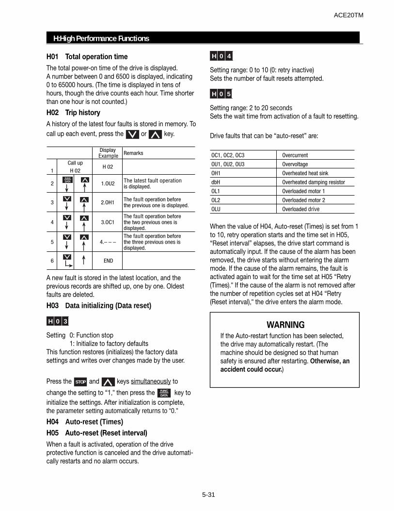
5-31
H 0 4
Setting range: 0 to 10 (0: retry inactive)Sets the number of fault resets attempted.
H 0 5
Setting range: 2 to 20 secondsSets the wait time from activation of a fault to resetting.
Drive faults that can be “auto-reset” are:
OC1, OC2, OC3 Overcurrent
OU1, OU2, OU3 Overvoltage
OH1 Overheated heat sink
dbH Overheated damping resistor
OL1 Overloaded motor 1
OL2 Overloaded motor 2
OLU Overloaded drive
When the value of H04, Auto-reset (Times) is set from 1to 10, retry operation starts and the time set in H05,“Reset interval” elapses, the drive start command isautomatically input. If the cause of the alarm has beenremoved, the drive starts without entering the alarmmode. If the cause of the alarm remains, the fault isactivated again to wait for the time set at H05 “Retry(Times)." If the cause of the alarm is not removed afterthe number of repetition cycles set at H04 “Retry(Reset interval)," the drive enters the alarm mode.
H01 Total operation timeThe total power-on time of the drive is displayed.A number between 0 and 6500 is displayed, indicating0 to 65000 hours. (The time is displayed in tens ofhours, though the drive counts each hour. Time shorterthan one hour is not counted.)
H02 Trip historyA history of the latest four faults is stored in memory. Tocall up each event, press the or key.
Display Example Remarks
1
2 1.OU2 The latest fault operation is displayed.
3 2.OH1 The fault operation before the previous one is displayed.
4 3.OC1The fault operation before the two previous ones is displayed.
5 4.– – – The fault operation before the three previous ones is displayed.
6 END
Call upH 02
H 02
FUNCDATA
A new fault is stored in the latest location, and theprevious records are shifted up, one by one. Oldestfaults are deleted.
H03 Data initializing (Data reset)
H 0 3
Setting 0: Function stop1: Initialize to factory defaults
This function restores (initializes) the factory datasettings and writes over changes made by the user.
Press the STOP and keys simultaneously to
change the setting to “1," then press the FUNCDATA key to
initialize the settings. After initialization is complete,the parameter setting automatically returns to “0."
H04 Auto-reset (Times)H05 Auto-reset (Reset interval)When a fault is activated, operation of the driveprotective function is canceled and the drive automati-cally restarts and no alarm occurs.
H:High Performance Functions
WARNINGIf the Auto-restart function has been selected,the drive may automatically restart. (Themachine should be designed so that humansafety is ensured after restarting. Otherwise, anaccident could occur.)
ACE20TM
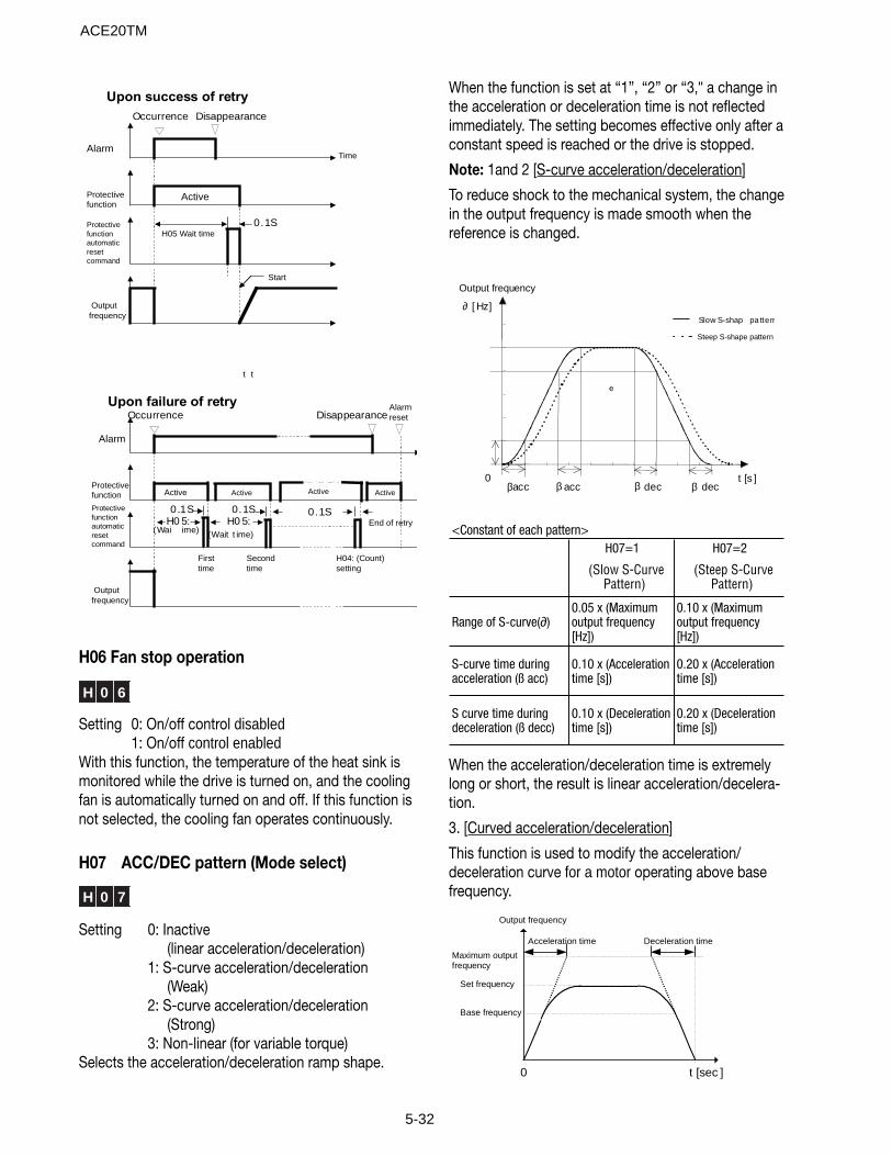
5-32
Alarm
Protectivefunction
Protectivefunctionautomaticresetcommand
Time
Outputfrequency
Upon failure of retry
Disappearance
Active
H05 Wait time0.1S
Start
Occurrence
ActiveActiveActive
H0 5:(Wait t ime)
0.1SH0 5:
(Wai
t t
ime)
0.1S 0.1SEnd of retry
Firsttime
Secondtime
H04: (Count)setting
Alarmreset
Upon success of retry
Occurrence Disappearance
Outputfrequency
Protectivefunctionautomaticresetcommand
Protectivefunction
Alarm
Active
H06 Fan stop operation
H 0 6
Setting 0: On/off control disabled1: On/off control enabled
With this function, the temperature of the heat sink ismonitored while the drive is turned on, and the coolingfan is automatically turned on and off. If this function isnot selected, the cooling fan operates continuously.
H07 ACC/DEC pattern (Mode select)
H 0 7
Setting 0: Inactive(linear acceleration/deceleration)
1: S-curve acceleration/deceleration(Weak)
2: S-curve acceleration/deceleration(Strong)
3: Non-linear (for variable torque)Selects the acceleration/deceleration ramp shape.
When the function is set at “1”, “2” or “3," a change inthe acceleration or deceleration time is not reflectedimmediately. The setting becomes effective only after aconstant speed is reached or the drive is stopped.
Note: 1and 2 [S-curve acceleration/deceleration]
To reduce shock to the mechanical system, the changein the output frequency is made smooth when thereference is changed.
Output frequency
0
∂ [ Hz]
t [s ]β decdecaccβacc
Steep S-shape pattern
Slow S-shap
e
pa ttern
β β
H07=1 H07=2
(Slow S-Curve Pattern)
(Steep S-Curve Pattern)
Range of S-curve(∂)0.05 x (Maximum output frequency [Hz])
0.10 x (Maximum output frequency [Hz])
S-curve time during acceleration (ß acc)
0.10 x (Acceleration time [s])
0.20 x (Acceleration time [s])
S curve time during deceleration (ß decc)
0.10 x (Deceleration time [s])
0.20 x (Deceleration time [s])
<Constant of each pattern>
When the acceleration/deceleration time is extremelylong or short, the result is linear acceleration/decelera-tion.
3. [Curved acceleration/deceleration]
This function is used to modify the acceleration/deceleration curve for a motor operating above basefrequency.
Deceleration time
Maximum outputfrequency
Output frequency
Base frequency
t [sec ]0
Acceleration time
Set frequency
ACE20TM

5-33
H09 Start mode (Rotating motor pickup)
H 0 9
This function smoothly starts a coasting motor after amomentary power failure.The speed of the motor is detected upon powerrecovery and that same frequency is applied to themotor. Therefore, the motor starts smoothly without ashock. However, when the coasting speed of the motorexceeds the setting of F03 “Maximum frequency 1” orof F15 “Frequency limiter (High)," the normal startingmethod is used.
Setting Regular Starting Restarting After Momentary Power Failure
0 Inactive Inactive
1 Inactive Active
2 Active Active
Description of setting:
1: This function is effective when the value of F14“Restart after momentary power failure (Operationselection)” is “2” or “3."
Starting is attempted at the same frequency as therotating motor.
2: Upon restart, after momentary power failure, thespeed of the coasting motor is detected andstarting is made at the same frequency as that ofthe coasting motor.
Note: When this function is used, use the followingsettings to determine the speed of the motor.
1. Set F09 Torque boost to “0”(automatic torque boost).
2. When a non-standard motor is used, or when the wiring length is long,perform P04 Tuning.
H10 Energy-saving operation
H 1 0
Setting 0: Inactive1: Active
When the output frequency is constant (constant speedoperation) and the load is light, and the setting of F09“Torque boost 1” is other than “0," the output voltage isautomatically lowered to minimize the power output.
Notes:
1. Use this function for fans or pumps only. If thisfunction is applied to a constant torque load or toan application with a rapidly changing load, therewill be a delay in the control response.
2. The energy-saving operation is automaticallycanceled during acceleration or deceleration orwhen the torque limiter function is activated.
H11 Dec mode
H 1 1
Setting 0: Normal(Deceleration to stop based onthe value of H07 “ACC/DEC pattern”)
1: Coast-to-stopThis function determines the stopping method of thedrive when a Stop command is entered.Note: This function is not activated when the setfrequency is set to zero. The function is activated onlywhen a Stop command is entered.
H12 Instantaneous overcurrent limiting
H 1 2
Setting 0: Inactive1: Active
An overcurrent trip generally occurs when current flowsabove the drive protective level, following a rapidchange in motor load. The instantaneous overcurrentlimiting function controls drive output and prohibits theflow of current exceeding the protective level, even ifthe load changes.
Since the operation level of the instantaneousovercurrent limiting function cannot be adjusted, thetorque limiting function must be used.
Motor generation torque may be reduced wheninstantaneous overcurrent limiting is applied. Set thisfunction to be inactive for equipment such as elevators,which are adversely affected by reduced motor genera-tion torque, in which case an overcurrent trip occurswhen the current flow exceeds the drive protectivelevel. A mechanical brake should be used to ensuresafety.
H13 Auto-restart (Restart time)
H 1 3
Setting range: 0.1 to 5 seconds
Instantaneous switching to another power line (whenthe power of an operating motor is cut off or powerfailure occurs) creates a large phase difference be-tween the line voltage and the voltage remaining in themotor, which may cause electrical or mechanicalfailure. To rapidly switch power lines, set the voltageattenuation time to wait for the voltage remaining in the
ACE20TM
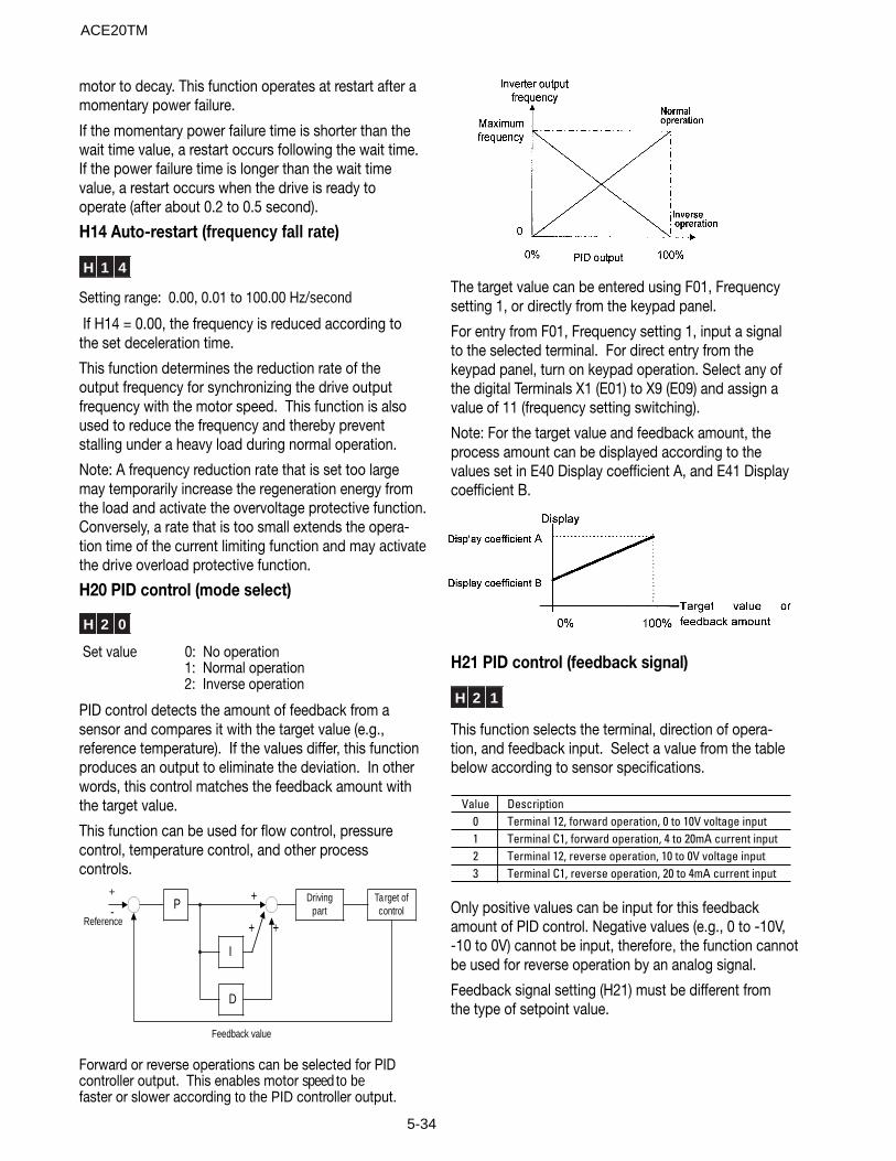
5-34
motor to decay. This function operates at restart after amomentary power failure.
If the momentary power failure time is shorter than thewait time value, a restart occurs following the wait time.If the power failure time is longer than the wait timevalue, a restart occurs when the drive is ready tooperate (after about 0.2 to 0.5 second).
H14 Auto-restart (frequency fall rate)
H 1 4
Setting range: 0.00, 0.01 to 100.00 Hz/second
If H14 = 0.00, the frequency is reduced according tothe set deceleration time.
This function determines the reduction rate of theoutput frequency for synchronizing the drive outputfrequency with the motor speed. This function is alsoused to reduce the frequency and thereby preventstalling under a heavy load during normal operation.
Note: A frequency reduction rate that is set too largemay temporarily increase the regeneration energy fromthe load and activate the overvoltage protective function.Conversely, a rate that is too small extends the opera-tion time of the current limiting function and may activatethe drive overload protective function.
H20 PID control (mode select)
H 2 0
Set value 0: No operation1: Normal operation2: Inverse operation
PID control detects the amount of feedback from asensor and compares it with the target value (e.g.,reference temperature). If the values differ, this functionproduces an output to eliminate the deviation. In otherwords, this control matches the feedback amount withthe target value.
This function can be used for flow control, pressurecontrol, temperature control, and other processcontrols.
Reference
P Drivingpart
Ta rget ofcontrol
I
D
+
+ +-
Feedback value
+
Forward or reverse operations can be selected for PIDcontroller output. This enables motor speed to befaster or slower according to the PID controller output.
The target value can be entered using F01, Frequencysetting 1, or directly from the keypad panel.
For entry from F01, Frequency setting 1, input a signalto the selected terminal. For direct entry from thekeypad panel, turn on keypad operation. Select any ofthe digital Terminals X1 (E01) to X9 (E09) and assign avalue of 11 (frequency setting switching).
Note: For the target value and feedback amount, theprocess amount can be displayed according to thevalues set in E40 Display coefficient A, and E41 Displaycoefficient B.
H21 PID control (feedback signal)
H 2 1
This function selects the terminal, direction of opera-tion, and feedback input. Select a value from the tablebelow according to sensor specifications.
Value Description0 Terminal 12, forward operation, 0 to 10V voltage input1 Terminal C1, forward operation, 4 to 20mA current input2 Terminal 12, reverse operation, 10 to 0V voltage input3 Terminal C1, reverse operation, 20 to 4mA current input
Only positive values can be input for this feedbackamount of PID control. Negative values (e.g., 0 to -10V,-10 to 0V) cannot be input, therefore, the function cannotbe used for reverse operation by an analog signal.
Feedback signal setting (H21) must be different fromthe type of setpoint value.
ACE20TM
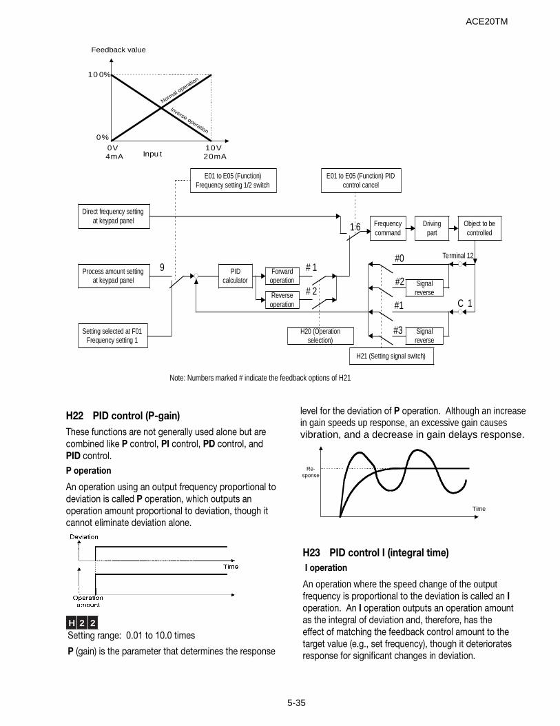
5-35
H22 PID control (P-gain)These functions are not generally used alone but arecombined like P control, PI control, PD control, andPID control.P operation
An operation using an output frequency proportional todeviation is called P operation, which outputs anoperation amount proportional to deviation, though itcannot eliminate deviation alone.
H 2 2Setting range: 0.01 to 10.0 times
P (gain) is the parameter that determines the response
level for the deviation of P operation. Although an increasein gain speeds up response, an excessive gain causes vibration, and a decrease in gain delays response.
Time
Re-sponse
H23 PID control I (integral time) I operation
An operation where the speed change of the outputfrequency is proportional to the deviation is called an Ioperation. An I operation outputs an operation amountas the integral of deviation and, therefore, has theeffect of matching the feedback control amount to thetarget value (e.g., set frequency), though it deterioratesresponse for significant changes in deviation.
Normal o
peration
Inverse operation
10 0%
0%
0V4mA
10V20mAInpu t
Feedback value
Note: Numbers marked # indicate the feedback options of H21
Direct frequency settingat keypad panel
Process amount settingat keypad panel
Setting selected at F01Frequency setting 1
PIDcalculator
Forwardoperation
Reverseoperation
Frequencycommand
Drivingpart
Object to becontrolled
Signalreverse
Signalreverse
H21 (Setting signal switch)
Terminal 12
C 1
#0
1 6
#1
#3
#2
E01 to E05 (Function) PIDcontrol cancel
9
E01 to E05 (Function)Frequency setting 1/2 switch
# 1
# 2
H20 (Operationselection)
ACE20TM
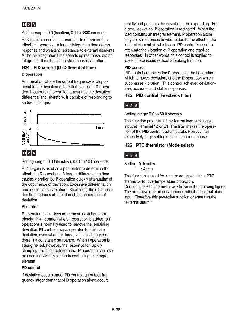
5-36
H 2 3
Setting range: 0.0 (Inactive), 0.1 to 3600 seconds
H23 I-gain is used as a parameter to determine theeffect of I operation. A longer integration time delaysresponse and weakens resistance to external elements.A shorter integration time speeds up response, but anintegration time that is too short causes vibration.
H24 PID control (D (Differential time)D operation
An operation where the output frequency is propor-tional to the deviation differential is called a D opera-tion. It outputs an operation amount as the deviationdifferential and, therefore, is capable of responding tosudden changes.
H 2 4
Setting range: 0.00 (Inactive), 0.01 to 10.0 seconds
H24 D-gain is used as a parameter to determine theeffect of a D operation. A longer differentiation timecauses vibration by P operation quickly attenuating atthe occurrence of deviation. Excessive differentiationtime could cause vibration. Shortening the differentia-tion time reduces attenuation at the occurrence ofdeviation.PI control
P operation alone does not remove deviation com-pletely. P + I control (where I operation is added to Poperation) is normally used to remove the remainingdeviation. PI control always operates to eliminatedeviation, even when the target value is changed orthere is a constant disturbance. When I operation isstrengthened, however, the response for rapidlychanging deviation deteriorates. P operation can alsobe used individually for loads containing an integralelement.PD control
If deviation occurs under PD control, an output fre-quency larger than that of D operation alone occurs
rapidly and prevents the deviation from expanding. Fora small deviation, P operation is restricted. When theload contains an integral element, P operation alonemay allow responses to vibrate due to the effect of theintegral element, in which case PD control is used toattenuate the vibration of P operation and stabilizeresponses. In other words, this control is applied toloads in processes without a braking function.
PID controlPID control combines the P operation, the I operationwhich removes deviation, and the D operation whichsuppresses vibration. This control achieves deviation-free, accurate, and stable responses.
H25 PID control (Feedback filter)
H 2 5
Setting range: 0.0 to 60.0 seconds
This function provides a filter for the feedback signalinput at Terminal 12 or C1. The filter makes the opera-tion of the PID control system stable. However, anexcessively large setting causes a poor response.
H26 PTC thermistor (Mode select)
H 2 6
Setting 0: Inactive1: Active
This function is used for a motor equipped with a PTCthermistor for overtemperature protection.Connect the PTC thermistor as shown in the following figure.The protective operation is common with the external alarminput. Therefore this protective function operates as the“external alarm."
ACE20TM
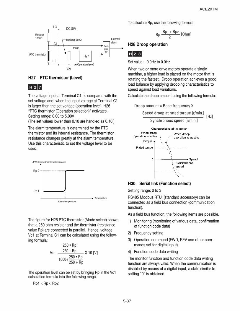
5-37
Resistor1000Ω
PTC
therm
H27
Com-para-tor
Externalalarm
DC10V
Resistor 250Ω
OV(Operation level)
1 3
C1
1 1
thermistor
H27 PTC thermistor (Level)
H 2 7
The voltage input at Terminal C1 is compared with theset voltage and, when the input voltage at Terminal C1is larger than the set voltage (operation level), H26“PTC thermistor (Operation selection)” activates.Setting range: 0.00 to 5.00V(The set values lower than 0.10 are handled as 0.10.)
The alarm temperature is determined by the PTCthermistor and its internal resistance. The thermistorresistance changes greatly at the alarm temperature.Use this characteristic to set the voltage level to beused.
/PTC thermistor internal resistance
R p 2
R p 1
Alarm temperatureTemperature
The figure for H26 PTC thermistor (Mode select) showsthat a 250 ohm resistor and the thermistor (resistancevalue Rp) are connected in parallel. Hence, voltageVc1 at Terminal C1 can be calculated using the follow-ing formula:
Vc1 X 10 [V]
250 • Rp250 + Rp
1000+ 250 • Rp250 + Rp
The operation level can be set by bringing Rp in the Vc1calculation formula into the following range.
Rp1 < Rp < Rp2
To calculate Rp, use the following formula:
RpRp1 + Rp2
[Ohm]2
H28 Droop operation
H 2 8
Set value : -9.9Hz to 0.0Hz
When two or more drive motors operate a singlemachine, a higher load is placed on the motor that isrotating the fastest. Droop operation achieves a goodload balance by applying drooping characteristics tospeed against load variations.Calculate the droop amount using the following formula:
Droop amount = Base frequency X
Speed droop at rated torque [r/min.][Hz]
Synchronous speed [r/min.]
H30 Serial link (Function select)Setting range: 0 to 3
RS485 Modbus RTU (standard accessory) can beconnected as a field bus connection (communicationfunction).
As a field bus function, the following items are possible.
1) Monitoring (monitoring of various data, confirmationof function code data)
2) Frequency setting
3) Operation command (FWD, REV and other com-mands set for digital input)
4) Function code data writing
The monitor function and function code data writingfunction are always valid. When the communication isdisabled by means of a digital input, a state similar tosetting “0” is obtained.
ACE20TM

5-38
H31 RS485 (address) throughThis function sets the various conditions of RS485communication. It must be set according to thespecifications of the host unit. Refer to Section 12 forprotocol and other specifications.
The mode of communication can be switched by adigital input. Mode settings are available through thecommunications link.
Setting Frequency Setting Operation Command
0 Invalid Invalid
1 Valid Invalid
2 Invalid Valid
3 Valid Valid
H 3 1
This function sets the station address of RS485.Setting range: 0 to 247 (0: Broadcast, 1 to 247 Query)
H32 RS485(Mode select on no response error)
H 3 2
This function sets the communication error handlingprocess and the error handling timer value.Setting range: 0 to 3
Setting Communication Error Handling Process
0 Immediate Er 8 trip (forced stop)
1 Operation continues until the timer elapses, then Er 8 trip.
2
Operation continues and retry is made until the timer elapses, then Er 8 trip upon a communication error or continued operation if no communication error.
3 Operation continues.
H33 RS485 (Timer)
H 3 3
This function sets the error handling timer value.Setting range: 0.0 to 60. 0 seconds
H34 RS485 (Baud rate)
H 3 4
This function sets the transmission speed.
Setting Transmission Speed0 1 9 2 0 0 bits/second1 9 6 0 O bits/second2 4 8 0 O bits/second3 2 4 0 O bits/second
H35 RS485 (Data length)
H 3 5
This function sets the data length.
Setting Data Length0 8 bits
H36 RS485 (Parity check)
H 3 6
This function sets the parity bit.
Setting Parity Bit0 None
1 Even
2 Odd
H37 RS485 (Stop bits)
H 3 7
This function sets the stop bit.
Setting Stop Bit0 2 bits1 1 bit
H38 RS485 (No response error detection time)
H 3 8
Setting range: 0 (no detection)1 to 60 seconds
In a system where there is always an access to thestation at certain intervals, no access caused by abroken wire or other errors is detected and the drivetrips in Er8.
H39 RS485 (Response interval)
H 3 9
Setting range: 0.00 to 1.00 second
This function sets the time taken for a response to be sent back to the host unit after a request.
ACE20TM
5-39
H40 Maximum temperature of heat sinkThe maximum value in each hour is displayed.
H41 Maximum effective currentThe maximum value in each hour is displayed.
H42 Main circuit capacitor lifeThe capacity of the capacitors in the DC Bus is dis-played in %. For the measuring conditions, refer toSection 8-2 (1) “Measurement of capacitance ofcapacitor in main circuit."
H43 Cooling fan operation timeIntegral hours is displayed. The displayed time is 0 to6500, indicating 0 to 65000 hours. (Though the dis-played value is in ten hours, the drive adds each hour.Operation shorter than one hour is not counted.)
H44 Drive ROM versionThe revision of the software in the drive is displayed.
H45 Keypad panel ROM versionThe revision of the software in the keypad panel isdisplayed.
H46 Option ROM versionFor drives with optional equipment, the revision of theoptional software is displayed.
ACE20TM

5-40
A: Alternative motor parameters
A01 Maximum frequency 2
A 0 1
The maximum frequency allowed by the drive for Motor2. This parameter functions in the same way as F03“Maximum output frequency 1." For the description,refer to F03 “Maximum output frequency 1."
A02 Base frequency 2
A 0 2
The output frequency in the constant torque zone ofMotor 2, that is, the output frequency at the ratedoutput voltage. This parameter functions in the sameway as F04 “Base frequency 1." For the description,refer to F04 “Base frequency 1."
A03 Rated voltage 2 (at base frequency 2)
A 0 3
The rated output voltage supplied to Motor 2. Thisparameter functions in the same way as F05 “Ratedvoltage 1." For the description, refer to F05 “Ratedvoltage 1."
A04 Maximum voltage 2 (at maximumfrequency 2)
A 0 4
The maximum output voltage of the drive for Motor 2.This parameter functions in the same way as F06“Maximum voltage 1." For the description, refer to F06“Maximum voltage 1."
A05 Torque boost 2
A 0 5
The torque boost function of Motor 2. This parameterfunctions in the same way as F09 “Torque boost 1." Forthe description, refer to F09 “Torque boost 1."
A06 Electronic thermal overload relay forMotor 2 (Select)
A07 Electronic thermal overload relay forMotor 2 (Level)
A08 Electronic thermal overload relay forMotor 2 (Thermal time constant)
A 0 6A 0 7A 0 8
These are the electronic thermal overload relay func-tions of Motor 2. These parameters function in thesame way as F10 through F12 "Electronic thermaloverload relay for Motor 1." For the description, refer toF10 through F12.
A09 Torque vector control 2
A 0 9
The torque vector function of Motor 2. This parameterfunctions in the same way as F42 “Torque vectorcontrol 1." For the description, refer to F42 “Torquevector control 1."
A10 Number of motor 2 poles
A 1 0
The number of poles of Motor 2. This parameterfunctions in the same way as P01 “Number of motor 1poles." For the description, refer to P01 “Number ofmotor 1 poles)."
A11 Motor 2 (Capacity)
A 1 1
The capacity of Motor 2. This parameter functions inthe same way as P02 “Motor 1 (Capacity)." For thedescription, refer to P02 “Motor 1 (Capacity)." How-ever, the motor data functions are A12 “Motor 2 (Ratedcurrent)," A15 “Motor 2 (No-load current)," A16 “Motor2 (%R1 setting)” and A17 “Motor 2 (%X setting)."
A12 Motor 2 (Rated current)
A 1 2 M 2 – L R
The rated current of Motor 2. This parameter functionsin the same way as P03 “Motor 1 (Rated current)." Forthe description, refer to P03 “Motor 1(Rated current)."
ACE20TM
5-41
A13 Motor 2 (Tuning)
A 1 3
Tuning of Motor 2. This parameter functions in thesame way as P04 “Motor 1 (Tuning)." For the descrip-tion, refer to P04 “Motor 1 (Tuning)."
A14 Motor 2 (Online turning)
A 1 4
Online tuning of Motor 2. This parameter functions inthe same way as P05 “Motor 1 (Online tuning)." For thedescription, refer to P05 “Motor 1 (Online turning)."
A15 Motor 2 (No-load current)
A 1 5
The no-load current of Motor 2. This parameterfunctions in the same way as P06 “Motor 1 (No-loadcurrent)." For the description, refer to P06 “Motor 1(No-load current)."
A16 Motor 2 (%R1 setting)A17 Motor 2 (%X setting)
A 1 6A 1 7
%R1 and %X of Motor 2. These parameters function inthe same way as P07 “Motor 1 (%R1 setting)” and P08“Motor 1 (%X setting)." For the description, refer to P07and P08.
A18 Motor 2 (Slip compensation control 2)
A 1 8
This function sets the slip compensation control ofMotor 2. This parameter functions in the same way asP09 “Motor 1 (Slip compensation control 1)." For thedescription, refer to P09 “Motor 1 (Slip compensationcontrol 1)."
A19 Motor 2 (Slip compensation responsetime 2)
A 1 9
This function sets the response time for slip compensa-tion of Motor 2. This parameter functions in the sameway as P10 “Motor 1 (Slip compensation responsetime)." For the description, refer to P10 “Motor 1 (Slipcompensation response time)."
ACE20TM

5-42
Notes
ACE20TM
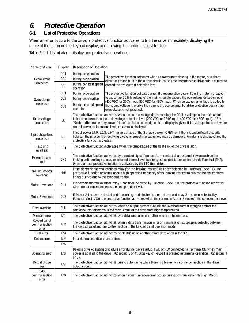
6-1
6. Protective Operation6-1 List of Protective OperationsWhen an error occurs to the drive, a protective function activates to trip the drive immediately, displaying thename of the alarm on the keypad display, and allowing the motor to coast-to-stop.
Table 6-1-1 List of alarm display and protective operations
Name of Alarm Display
OC1 During accelerationOC2 During deceleration
OC3 During constant speed operation
OU1 During accelerationOU2 During deceleration
OU3 During constant speed operation
Undervoltage protection
LU
Input phase loss protection
Lin
Heat sink overheat
OH1
External alarm input
OH2
Braking resistor overheat
dbH
Motor 1 overload OL1
Motor 2 overload OL2
Drive overload OLU
Memory error Er1
Keypad panel communication
errorEr2
CPU error Er3
Option error Er4
Er5
Operating error Er6
Output phase loss
Er7
RS485 communication
errorEr8
Overcurrent protection
The protective function activates by a data writing error or other errors in the memory.
The protective function activates when a data transmission error or transmission stoppage is detected between the keypad panel and the control section in the keypad panel operation mode.
The protective function activates by electric noise or other errors developed in the CPU.
If the electronic thermal overload relay (for the braking resistor) has been selected by Function Code F13, the protective function activates upon a high operation frequency of the braking resistor to prevent the resistor from being burned due to the temperature rise.
If electronic thermal overload relay 1 has been selected by Function Code F10, the protective function activates when motor current exceeds the set operation level.
The protective function activates by a contact signal from an alarm contact of an external device such as the braking unit, braking resistor, or external thermal overload relay connected to the control circuit Terminal (THR). Or an overheat protective function is activated by the PTC thermistor.
The protective function activates during auto tuning when there is a broken wire or no connection in the drive output circuit.
The protective function activates when a communication error occurs during communication through RS485.
Error during operation of an option.
Detects drive operating procedure error during drive startup. FWD or REV connected to Terminal CM when main power is applied to the drive (F02 setting 3 or 4). Stop key on keypad is pressed in terminal operation (F02 setting 1 or 3).
Description of Operation
The protective function activates when an overcurrent flowing in the motor, or a short circuit or ground fault in the output circuit, causes the instantaneous drive output current to exceed the overcurrent detection level.
Overvoltage protection
The protective function activates when the regenerative power from the motor increases to cause the DC link voltage of the main circuit to exceed the overvoltage detection level (400 VDC for 230V input, 800 VDC for 460V input). When an excessive voltage is added to the source voltage, the drive trips due to the overvoltage, but drive protection against the overvoltage is not practical.
If Motor 2 has been selected and is running, and electronic thermal overload relay 2 has been selected by Function Code A06, the protective function activates when the current in Motor 2 exceeds the set operation level.
The protective function activates when an output current exceeds the overload current rating to protect the semiconductor elements in the main circuit of the drive from high temperatures.
The protective function activates when the source voltage drops causing the DC link voltage in the main circuit to become lower than the undervoltage detection level (200 VDC for 230V input, 400 VDC for 460V input). If F14 "Restart after momentary power failure" has been selected, no alarm display is given. If the voltage drops below the control power maintenance level, no alarm is displayed.
If Input power L1/R, L2/S, L3/T has any phase of the 3 phase power "OPEN" or if there is a significant disparity between the phases, the rectifying diodes or smoothing capacitors may be damaged. An alarm is displayed and the protective function activates.
The protective function activates when the temperature of the heat sink of the drive is high.
ACE20TM
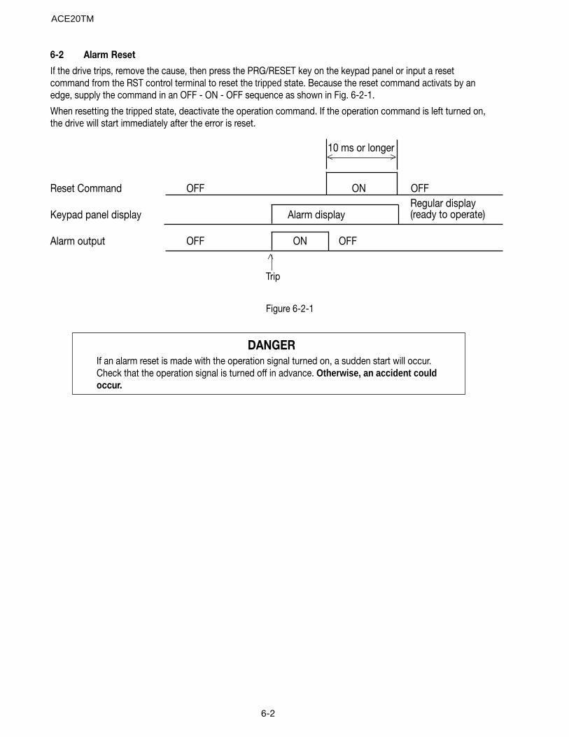
6-2
DANGERIf an alarm reset is made with the operation signal turned on, a sudden start will occur.Check that the operation signal is turned off in advance. Otherwise, an accident couldoccur.
6-2 Alarm Reset
If the drive trips, remove the cause, then press the PRG/RESET key on the keypad panel or input a resetcommand from the RST control terminal to reset the tripped state. Because the reset command activats by anedge, supply the command in an OFF - ON - OFF sequence as shown in Fig. 6-2-1.
When resetting the tripped state, deactivate the operation command. If the operation command is left turned on,the drive will start immediately after the error is reset.
Reset Command OFF ON OFF
Keypad panel display Alarm display
Alarm output OFF ON OFF
10 ms or longer
Regular display(ready to operate)
Trip
Figure 6-2-1
< >
>
ACE20TM
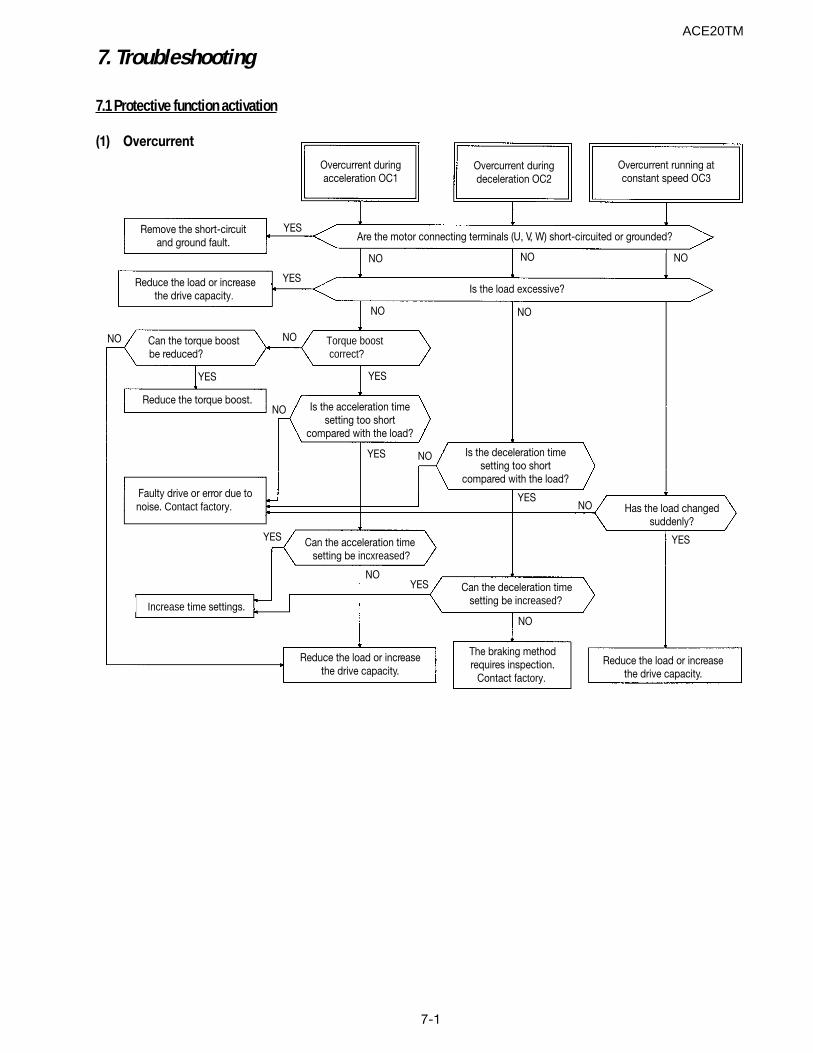
7-1
7. Troubleshooting
7.1 Protective function activation
(1) Overcurrent
Overcurrent duringacceleration OC1
Overcurrent duringdeceleration OC2
Overcurrent running atconstant speed OC3
Are the motor connecting terminals (U, V, W) short-circuited or grounded?
Is the load excessive?
Torque boostcorrect?
Is the acceleration timesetting too short
compared with the load?
Is the deceleration timesetting too short
compared with the load?
Has the load changedsuddenly?
Can the acceleration timesetting be incxreased?
Remove the short-circuitand ground fault.
Reduce the load or increasethe drive capacity.
Can the torque boostbe reduced?
Reduce the torque boost.
Faulty drive or error due tonoise. Contact factory.
Increase time settings.
Reduce the load or increasethe drive capacity.
Can the deceleration timesetting be increased?
The braking methodrequires inspection.
Contact factory.
Reduce the load or increasethe drive capacity.
YES
NO
YES
YES
NO
NO
NONONO
NO
NO
YES
YES
YES
YES
NO
NO
YES
NO
YES
NO
ACE20TM
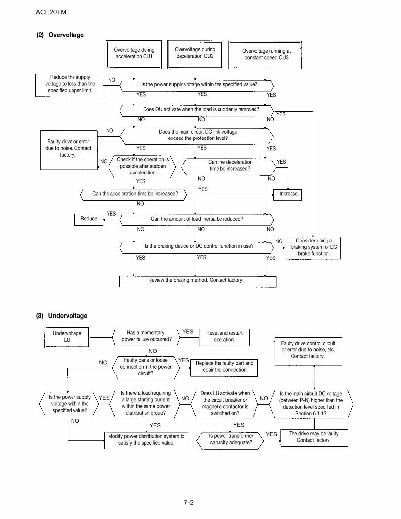
7-2
Overvoltage duringacceleration OU1
(2) Overvoltage
Overvoltage duringdeceleration OU2
Overvoltage running atconstant speed OU3
Reduce the supplyvoltage to less than thespecified upper limit.
Faulty drive or errordue to noise. Contact
factory.
Is the power supply voltage within the specified value?
Does OU activate when the load is suddenly removed?
Does the main circuit DC link voltageexceed the protection level?
Check if the operation ispossible after sudden
acceleration.
Can the decelerationtime be increased?
Can the acceleration time be increased?
Can the amount of load inertia be reduced?
Increase.
Reduce.
Is the braking device or DC control function in use?
Review the braking method. Contact factory.
Consider using abraking system or DC
brake function.
Faulty drive control circuitor error due to noise, etc.
Contact factory.
Is the main circuit DC voltage(between P-N) higher than the
detection level specified inSection 6.1.1?
The drive may be faulty.Contact factory.
Reset and restartoperation.
Does LU activate whenthe circuit breaker ormagnetic contactor is
switched on?
Is power transformercapacity adequate?
Replace the faulty part andrepair the connection.
Has a momentarypower failure occurred?
Faulty parts or looseconnection in the power
circuit?
Is there a load requiringa large starting currentwithin the same power
distribution group?
Modify power distribution system tosatisfy the specified value.
UndervoltageLU
Is the power supplyvoltage within thespecified value?
YES YES YES
YES YES YES
YES YES YES
YES
YES
NO
YES
NO NO NO
NO NO NO
NO
NONOYES
NO
NO
YES
(3) Undervoltage
NO
ACE20TM
YES
YES
YES
YES YES
YES
NO
NO
NO NO
NO
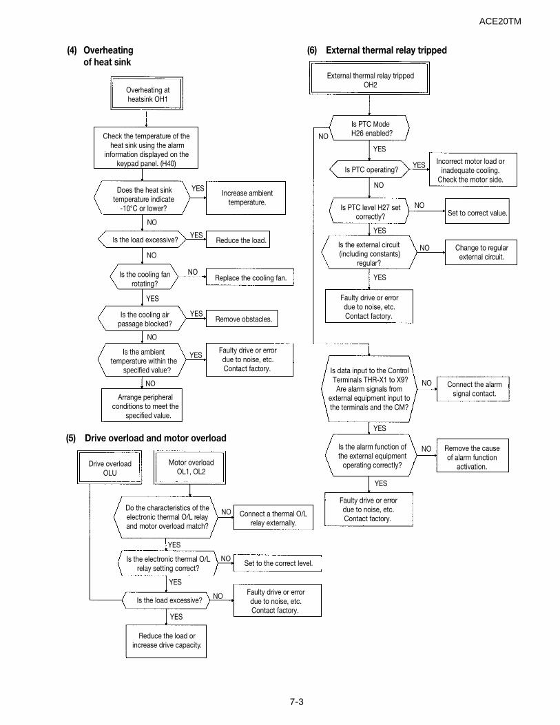
7-3
(4) Overheatingof heat sink
(6) External thermal relay tripped
(5) Drive overload and motor overload
Overheating atheatsink OH1
Check the temperature of theheat sink using the alarm
information displayed on thekeypad panel. (H40)
Does the heat sinktemperature indicate
-10°C or lower?
Is the load excessive? Reduce the load.
Is the cooling fanrotating?
Replace the cooling fan.
Is the cooling airpassage blocked?
Is the ambienttemperature within the
specified value?
Arrange peripheralconditions to meet the
specified value.
Remove obstacles.YES
Faulty drive or errordue to noise, etc.Contact factory.
YES
NO
NO
NO
NO
NO
YES
YES
External thermal relay trippedOH2
Is PTC ModeH26 enabled?
Is PTC operating?Incorrect motor load or
inadequate cooling.Check the motor side.
Set to correct value.
Change to regularexternal circuit.
Is PTC level H27 setcorrectly?
Is the external circuit(including constants)
regular?
Faulty drive or errordue to noise, etc.Contact factory.
Is data input to the ControlTerminals THR-X1 to X9?Are alarm signals from
external equipment input tothe terminals and the CM?
Connect the alarmsignal contact.
Is the alarm function ofthe external equipment
operating correctly?
Faulty drive or errordue to noise, etc.Contact factory.
Remove the causeof alarm function
activation.Drive overloadOLU
Motor overloadOL1, OL2
Do the characteristics of theelectronic thermal O/L relayand motor overload match?
Connect a thermal O/Lrelay externally.
Is the electronic thermal O/Lrelay setting correct?
Set to the correct level.
Faulty drive or errordue to noise, etc.Contact factory.
Is the load excessive?
Reduce the load orincrease drive capacity.
YES
YES
YES
YES
NO
NO
NO
NO
NO
NO
YES
YES
NO
NO
NO
YES
YES
YES
YESIncrease ambient
temperature.
ACE20TM
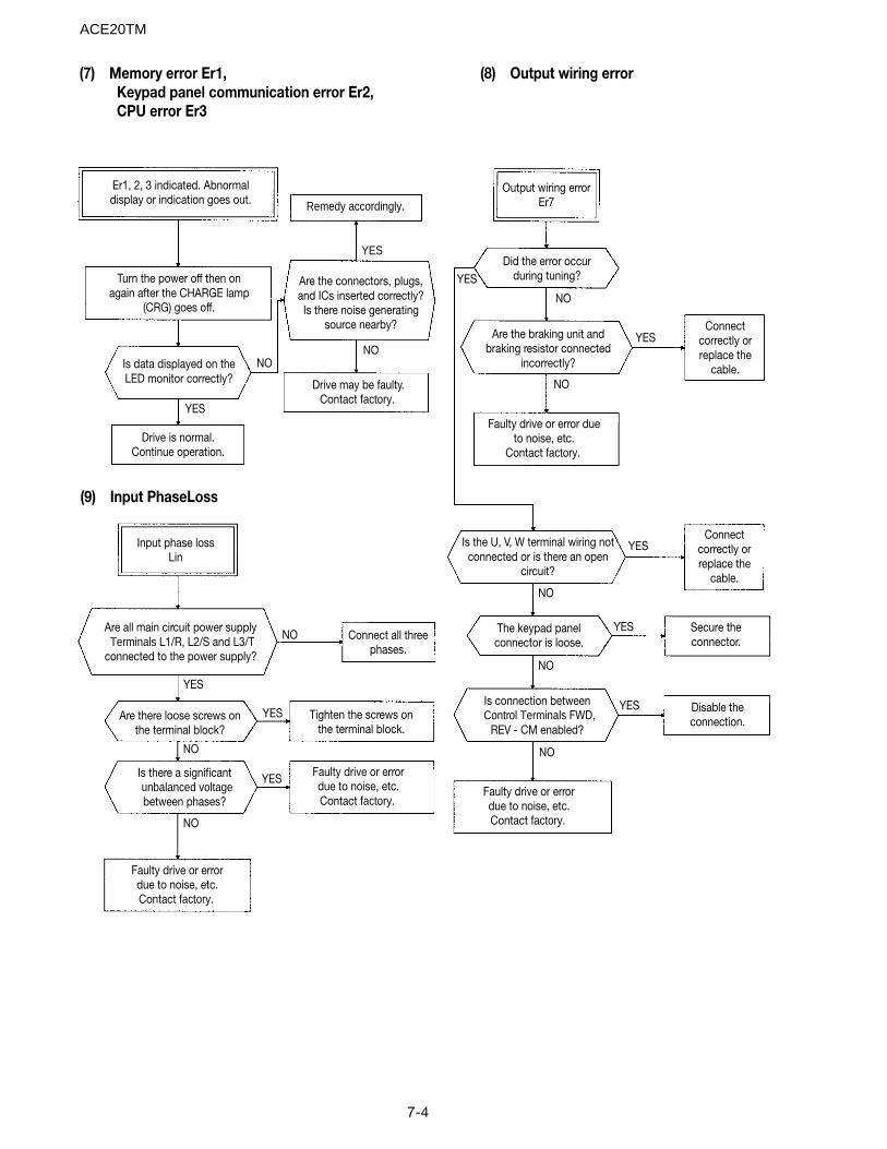
7-4
(7) Memory error Er1, Keypad panel communication error Er2, CPU error Er3
(8) Output wiring error
(9) Input PhaseLoss
Remedy accordingly.
Er1, 2, 3 indicated. Abnormaldisplay or indication goes out.
Are there loose screws onthe terminal block?
Turn the power off then onagain after the CHARGE lamp
(CRG) goes off.
Is data displayed on theLED monitor correctly?
Drive is normal.Continue operation.
Are the connectors, plugs,and ICs inserted correctly?Is there noise generating
source nearby?
Drive may be faulty.Contact factory.
Output wiring errorEr7
Did the error occurduring tuning?
Are the braking unit andbraking resistor connected
incorrectly?
Faulty drive or error dueto noise, etc.
Contact factory.
Connectcorrectly orreplace the
cable.
Input phase lossLin
Are all main circuit power supplyTerminals L1/R, L2/S and L3/T
connected to the power supply?
Is the U, V, W terminal wiring notconnected or is there an open
circuit?
The keypad panelconnector is loose.
Connect all threephases.
Connectcorrectly orreplace the
cable.
Secure theconnector.
Disable theconnection.
Is connection betweenControl Terminals FWD,
REV - CM enabled?Tighten the screws on
the terminal block.
Faulty drive or errordue to noise, etc.Contact factory.
Is there a significantunbalanced voltagebetween phases?
Faulty drive or errordue to noise, etc.Contact factory.
Faulty drive or errordue to noise, etc.Contact factory.
NO
YES
YES
NO
NO
NO
YES
YES
YES
YES
YES
NO
NO
NO
YES
YES
YES
NO
NO
NO
ACE20TM
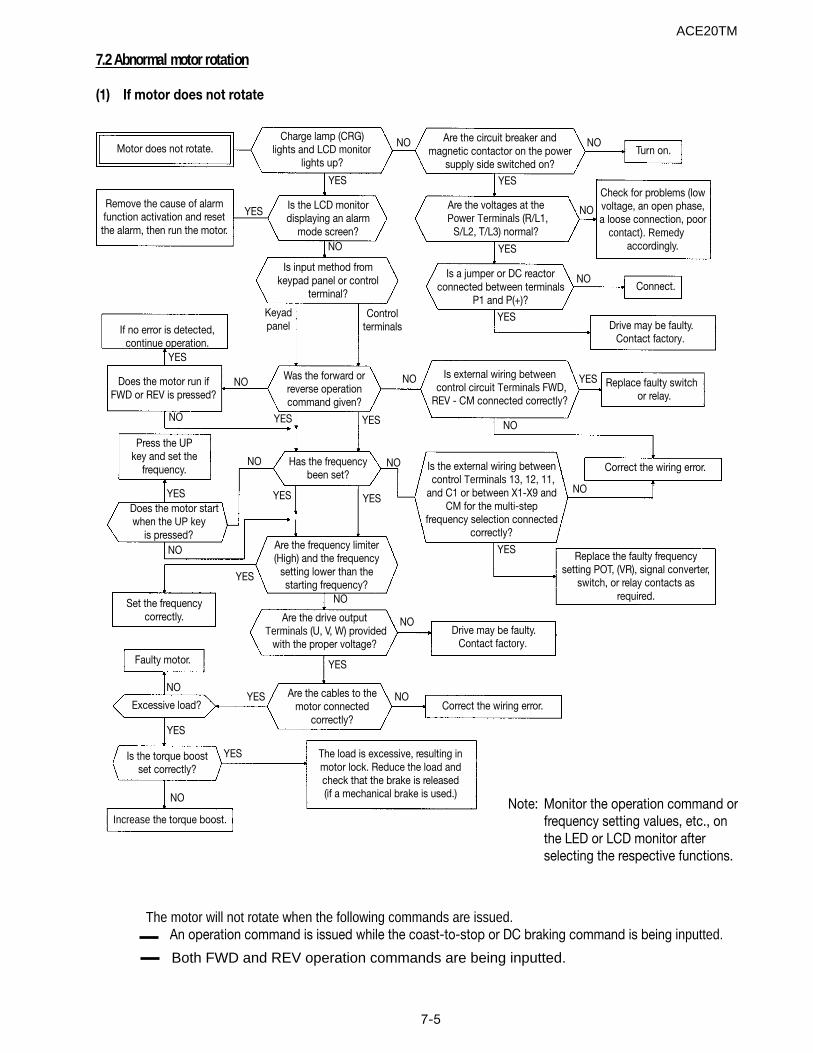
7-5
Check for problems (lowvoltage, an open phase,a loose connection, poor
contact). Remedyaccordingly.
7.2 Abnormal motor rotation
(1) If motor does not rotate
The motor will not rotate when the following commands are issued.An operation command is issued while the coast-to-stop or DC braking command is being inputted.
Motor does not rotate.Charge lamp (CRG)
lights and LCD monitorlights up?
Are the circuit breaker andmagnetic contactor on the power
supply side switched on?Turn on.
Are the voltages at thePower Terminals (R/L1,
S/L2, T/L3) normal?
Is the LCD monitordisplaying an alarm
mode screen?
Is a jumper or DC reactorconnected between terminals
P1 and P(+)?Connect.
Drive may be faulty.Contact factory.
Is input method fromkeypad panel or control
terminal?
Remove the cause of alarmfunction activation and resetthe alarm, then run the motor.
If no error is detected,continue operation.
Was the forward orreverse operationcommand given?
Is external wiring betweencontrol circuit Terminals FWD,
REV - CM connected correctly?
Correct the wiring error.
Replace faulty switchor relay.
Has the frequencybeen set?
Press the UPkey and set the
frequency.
Does the motor run ifFWD or REV is pressed?
Does the motor startwhen the UP key
is pressed?Are the frequency limiter(High) and the frequency
setting lower than thestarting frequency?
Is the external wiring betweencontrol Terminals 13, 12, 11,
and C1 or between X1-X9 andCM for the multi-step
frequency selection connectedcorrectly?
Replace the faulty frequencysetting POT, (VR), signal converter,
switch, or relay contacts asrequired.
Are the drive outputTerminals (U, V, W) provided
with the proper voltage?
Set the frequencycorrectly.
Faulty motor.
Are the cables to themotor connected
correctly?Correct the wiring error.
The load is excessive, resulting inmotor lock. Reduce the load andcheck that the brake is released(if a mechanical brake is used.)
Is the torque boostset correctly?
Excessive load?
Increase the torque boost.Note: Monitor the operation command or
frequency setting values, etc., onthe LED or LCD monitor afterselecting the respective functions.
Drive may be faulty.Contact factory.
Keyadpanel
Controlterminals
NO
YES
YES YES
YES
YES
YES YES
YES
NO
NO
NO
NONO
NO
NO NO
NO
NO
NO
NO
NO
NO
YES
YES
YES
NO
YES
YES
YES
YESYESYES
NO
NO
YES
ACE20TM
Both FWD and REV operation commands are being inputted.
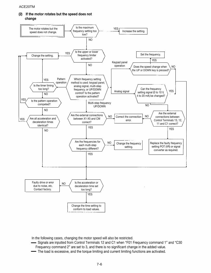
7-6
(2) If the motor rotates but the speed does notchange
In the following cases, changing the motor speed will also be restricted.Signals are inputted from Control Terminals 12 and C1 when “F01 Frequency command 1” and “C30
Frequency command 2” are set to 3, and there is no significant change in the added value.The load is excessive, and the torque limiting and current limiting functions are activated.
The motor rotates but thespeed does not change.
YES
Change the setting.
Is the maximumfrequency setting too
low?
Is the upper or lowerfrequency limiter
activated?
Is the timer timingtoo long?
Which frequency settingmethod is used: keypad panel,
analog signal, multi-stepfrequency, or UP/DOWNcontrol? Is the patternoperation activated?
Is the pattern operationcompeted?
Are all acceleration anddeceleration times
identical?
Are the external connectionsbetween X1-X5 and CM
correct?
Increase the setting.
Set the frequency.
Does the speed change whenthe UP or DOWN key is pressed?
Can the frequencysetting signal (0 to 10 V,
4 to 20 mA) be changed?
Correct the connectionerror.
Replace the faulty frequencysetting POT (VR) or signal
converter as required.
YES
YES
Patternoperation
Keypad paneloperation
Analog signal
Multi-step frequencyUP/DOWN
YES
NO
NO
NO
YES
YES
NO
NO
NO
YES
YES
NO
NO NO
NO
YES
YES
Change the frequencysetting.
Are the externalconnections between
Control Terminals 13, 12,11 and C1 correct?
Are the frequencies foreach multi-step
frequency different?
Is the acceleration ordeceleration time set
too long?
Faulty drive or errordue to noise, etc.Contact factory.
Change the time setting toconform to load values.
YES
NO
ACE20TM
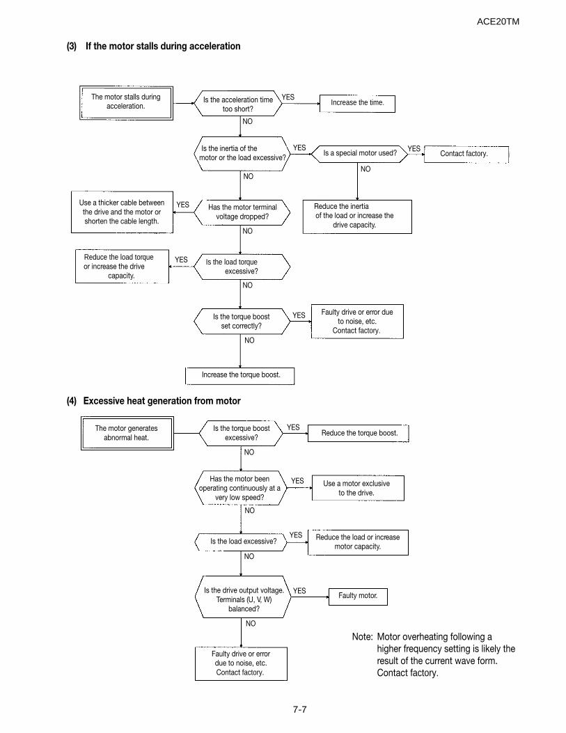
7-7
(3) If the motor stalls during acceleration
The motor stalls duringacceleration.
YES
NO
Is the acceleration timetoo short?
Increase the time.
Is the inertia of themotor or the load excessive?
Is a special motor used? Contact factory.
Use a thicker cable betweenthe drive and the motor orshorten the cable length.
Has the motor terminalvoltage dropped?
Reduce the inertia of the load or increase the
drive capacity.
Is the load torqueexcessive?
Reduce the load torqueor increase the drive
capacity.
Is the torque boostset correctly?
Faulty drive or error dueto noise, etc.
Contact factory.
Increase the torque boost.
The motor generatesabnormal heat.
Is the torque boostexcessive?
Reduce the torque boost.
Has the motor beenoperating continuously at a
very low speed?
Use a motor exclusiveto the drive.
Is the load excessive? Reduce the load or increasemotor capacity.
Is the drive output voltage.Terminals (U, V, W)
balanced?
Faulty motor.
Faulty drive or errordue to noise, etc.Contact factory.
Note: Motor overheating following ahigher frequency setting is likely theresult of the current wave form.Contact factory.
YES
NO
YES
NO
YES
NO
NO
NO
YES
YES
YES
YES
YES
YES
NO
NO
NO
NO
(4) Excessive heat generation from motor
ACE20TM

7-8
Notes:ACE20TM
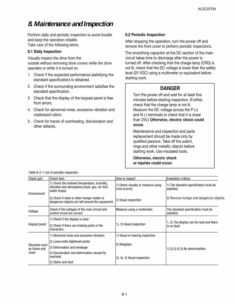
8-1
8. Maintenance and InspectionPerform daily and periodic inspection to avoid troubleand keep the operation reliable. Take care of the following items.
8.1 Daily Inspection
Visually inspect the drive from theoutside without removing drive covers while the driveoperates or while it is turned on.
1. Check if the expected performance (satisfying thestandard specification) is obtained.
2. Check if the surrounding environment satisfies thestandard specification.
3 Check that the display of the keypad panel is freefrom errors.
4. Check for abnormal noise, excessive vibration andunpleasant odors.
5. Check for traces of overheating, discoloration andother defects.
8.2 Periodic Inspection
After stopping the operation, turn the power off andremove the front cover to perform periodic inspections.
The smoothing capacitor at the DC section of the maincircuit takes time to discharge after the power isturned off. After checking that the charge lamp (CRG) isnot lit, check that the DC voltage is lower than the safetylevel (25 VDC) using a multimeter or equivalent beforestarting work.
Check part Check item How to inspect Evaluation criteria1) Check the ambient temperature, humidity, vibration and atmosphere (dust, gas, oil mist, water drops).
1) Check visually or measure using instruments.
1) The standard specification must be satisfied.
2) Check if tools or other foreign matter or dangerous objects are left around the equipment. 2) Visual inspection 2) Remove foreign and dangerous objects.
Voltage Check if the voltages of the main circuit and control circuit are correct.
Measure using a multimeter. The standard specification must be satisfied.
1) Check if the display is clear.
2) Check if there are missing parts in the characters.
1) Abnormal noise and excessive vibration 1) Visual or hearing inspection
2) Loose bolts (tightened parts)
3) Deformation and breakage
4) Discoloration and deformation caused by overheat
5) Stains and dust
Table 8-2-1 List of periodic inspection
Structure such as frame and cover
Keypad panel
Environment
3), 4), 5) Visual inspection
2) Retighten1),2),3),4),5) No abnormalities
1, 2) The display can be read and there is no fault.1), 2) Visual inspection
DANGERTurn the power off and wait for at least fiveminutes before starting inspection. (Further,check that the charge lamp is not lit.Measure the DC voltage across the P (+)and N (-) terminals to check that it is lowerthan 25V.) Otherwise, electric shock couldoccur.
Maintenance and inspection and partsreplacement should be made only byqualified persons. Take off the watch,rings and other metallic objects beforestarting work. Use insulated tools.
Otherwise, electric shockor injuries could occur.
ACE20TM
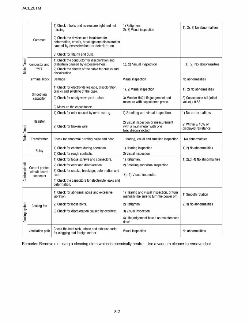
8-2
1) Check if bolts and screws are tight and not missing.
1) Retighten. 2), 3) Visual inspection 1), 2), 3) No abnormalities
2) Check the devices and insulators for deformation, cracks, breakage and discoloration caused by excessive heat or deterioration.
3) Check for stains and dust.
1) Check the conductor for discoloration and distortion caused by excessive heat. 1), 2) Visual inspection 1), 2) No abnormalities2) Check the sheath of the cable for cracks and discoloration.
Damage Visual inspection No abnormalities
1) Check for electrolyte leakage, discoloration, cracks and swelling of the case. 1), 2) Visual inspection 1), 2) No abnormalities
2) Check for safety valve protrusion. 3) Monitor H42 Life judgement and measure with capacitance probe.
3) Capacitance ÅÜ (Initial value) x 0.85
3) Measure the capacitance.
1) Check for odor caused by overheating. 1) Smelling and visual inspection 1) No abnormalities
2) Check for broken wire.2) Visual inspection or measurement with a multimeter with one lead disconnected
2) Within ± 10% of displayed resistance
Check for abnormal buzzing noise and odor. Hearing, visual and smelling inspection No abnormalities
1) Check for chatters during operation. 1) Hearing inspection 1),2) No abnormalities
2) Check for rough contacts. 2) Visual inspection
1) Check for loose screws and connectors. 1) Retighten. 1),2),3),4) No abnormalities
2) Check for odor and discoloration. 2) Smelling and visual inspection
3) Check for cracks, breakage, deformation and rust. 3), 4) Visual inspection
4) Check the capacitors for electrolyte leaks and deformation.
1) Check for abnormal noise and excessive vibration.
1) Hearing and visual inspection, or turn manually (be sure to turn the power off). 1) Smooth rotation
2) Check for loose bolts. 2) Retighten. 2),3) No abnormalities
3) Check for discoloration caused by overheat. 3) Visual inspection
4) Life judgement based on maintenance data*
Check the heat sink, intake and exhaust ports for clogging and foreign matter. Visual inspection No abnormalitiesVentilation path
Cool
ing
syst
em
Common
Conductor and wire
Terminal block
Smoothing capacitor
Resistor
Transformer
Relay
Control printed circuit board,
connector
Mai
n Ci
rcui
tM
ain
Circ
uit
Cont
rol c
ircui
t
Cooling fan
Remarks: Remove dirt using a cleaning cloth which is chemically neutral. Use a vacuum cleaner to remove dust.
ACE20TM
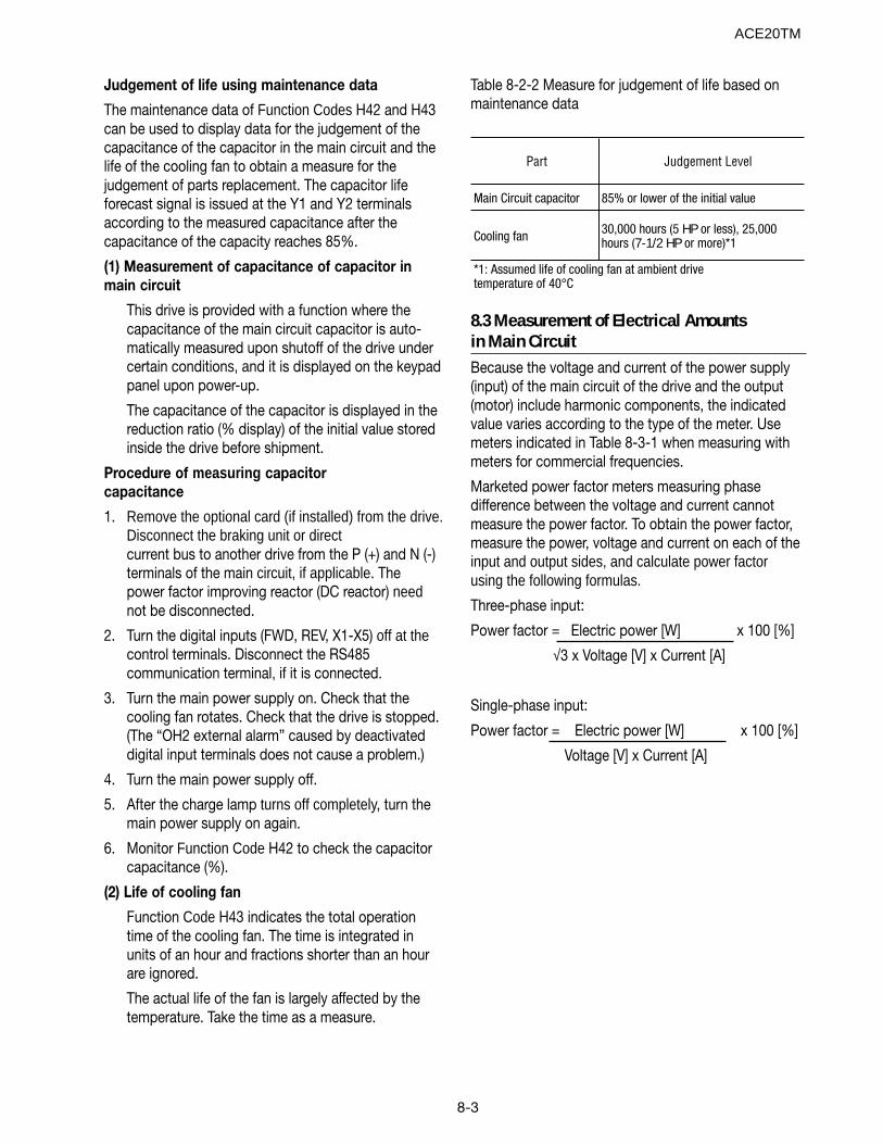
8-3
Judgement of life using maintenance data
The maintenance data of Function Codes H42 and H43can be used to display data for the judgement of thecapacitance of the capacitor in the main circuit and thelife of the cooling fan to obtain a measure for thejudgement of parts replacement. The capacitor lifeforecast signal is issued at the Y1 and Y2 terminalsaccording to the measured capacitance after thecapacitance of the capacity reaches 85%.
(1) Measurement of capacitance of capacitor inmain circuit
This drive is provided with a function where thecapacitance of the main circuit capacitor is auto-matically measured upon shutoff of the drive undercertain conditions, and it is displayed on the keypadpanel upon power-up.
The capacitance of the capacitor is displayed in thereduction ratio (% display) of the initial value storedinside the drive before shipment.
Procedure of measuring capacitorcapacitance
1. Remove the optional card (if installed) from the drive.Disconnect the braking unit or directcurrent bus to another drive from the P (+) and N (-)terminals of the main circuit, if applicable. Thepower factor improving reactor (DC reactor) neednot be disconnected.
2. Turn the digital inputs (FWD, REV, X1-X5) off at thecontrol terminals. Disconnect the RS485communication terminal, if it is connected.
3. Turn the main power supply on. Check that thecooling fan rotates. Check that the drive is stopped.(The “OH2 external alarm” caused by deactivateddigital input terminals does not cause a problem.)
4. Turn the main power supply off.
5. After the charge lamp turns off completely, turn themain power supply on again.
6. Monitor Function Code H42 to check the capacitorcapacitance (%).
(2) Life of cooling fan
Function Code H43 indicates the total operationtime of the cooling fan. The time is integrated inunits of an hour and fractions shorter than an hourare ignored.
The actual life of the fan is largely affected by thetemperature. Take the time as a measure.
Table 8-2-2 Measure for judgement of life based onmaintenance data
Part Judgement Level
Main Circuit capacitor 85% or lower of the initial value
Cooling fan 30,000 hours (5 HP or less), 25,000 hours (7-1/2 HP or more)*1
*1: Assumed life of cooling fan at ambient drive temperature of 40°C
8.3 Measurement of Electrical Amountsin Main CircuitBecause the voltage and current of the power supply(input) of the main circuit of the drive and the output(motor) include harmonic components, the indicatedvalue varies according to the type of the meter. Usemeters indicated in Table 8-3-1 when measuring withmeters for commercial frequencies.
Marketed power factor meters measuring phasedifference between the voltage and current cannotmeasure the power factor. To obtain the power factor,measure the power, voltage and current on each of theinput and output sides, and calculate power factorusing the following formulas.
Three-phase input:
Power factor = Electric power [W] x 100 [%]
√3 x Voltage [V] x Current [A]
Single-phase input:
Power factor = Electric power [W] x 100 [%]
Voltage [V] x Current [A]
ACE20TM
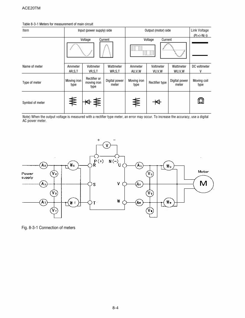
8-4
Item Link Voltage(P(+)-N(-))
Name of meter Ammeter Voltmeter Wattmeter Ammeter Voltmeter Wattmeter DC voltmeter
AR,S,T VR,S,T WR,S,T AU,V,W VU,V,W WU,V,W V
Type of meter Moving iron type
Rectifier or moving iron
type
Digital power meter
Moving iron type Rectifier type Digital power
meterMoving coil
type
Symbol of meter
Note) When the output voltage is measured with a rectifier type meter, an error may occur. To increase the accuracy, use a digital AC power meter.
Output (motor) sideInput (power supply) side
Table 8-3-1 Meters for measurement of main circuit
Voltage CurrentVoltage Current
Fig. 8-3-1 Connection of meters
ACE20TM
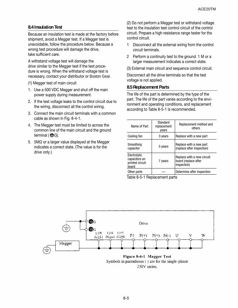
8-5
(2) Do not perform a Megger test or withstand voltagetest to the insulation test control circuit of the controlcircuit. Prepare a high resistance range tester for thecontrol circuit.
1 Disconnect all the external wiring from the controlcircuit terminals.
2 Perform a continuity test to the ground. 1 M or alarger measurement indicates a correct state.
(3) External main circuit and sequence control circuit.
Disconnect all the drive terminals so that the testvoltage is not applied.
8.5 Replacement PartsThe life of the part is determined by the type of thepart. The life of the part varies according to the envi-ronment and operating conditions, and replacementaccording to Table 8-5-1 is recommended.
Name of PartStandard
replacement years
Replacement method and others
Cooling fan 3 years Replace with a new part
Smoothing capacitor 5 years Replace with a new part
(replace after inspection)
Electrolytic capacitors on printed circuit board
7 yearsReplace with a new circuit board (replace after inspection)
Other parts — Determine after inspection
Table 8-5-1 Replacement parts
8.4 Insulation TestBecause an insulation test is made at the factory beforeshipment, avoid a Megger test. If a Megger test isunavoidable, follow the procedure below. Because awrong test procedure will damage the drive,take sufficient care.
A withstand voltage test will damage thedrive similar to the Megger test if the test proce-dure is wrong. When the withstand voltage test isnecessary, contact your distributor or Boston Gear.
(1) Megger test of main circuit
1. Use a 500 VDC Megger and shut off the mainpower supply during measurement.
2. If the test voltage leaks to the control circuit due tothe wiring, disconnect all the control wiring.
3. Connect the main circuit terminals with a commoncable as shown in Fig. 8-4-1.
4. The Megger test must be limited to across thecommon line of the main circuit and the groundterminal ( G).
5. 5MΩ or a larger value displayed at the Meggerindicates a correct state. (The value is for thedrive only.)
ACE20TM

8-6
Notes:
ACE20TM
9-1
9. Warranty, Parts and Service
The purpose of this section is to provide specificinstructions to the user of the standard drive referencedin this manual regarding warranty administration and howto obtain assistance on both in-warranty and out-of-warranty equipment.
For all warranty procedures, refer to section 10 of thisinstruction manual to identify the part or assembly.
If assistance is required to determine warranty status,identify defective parts, or obtain the name of your localdistributor, call:
Boston Gear14 Hayward StreetQuincy, MA 02171 USAPhone: + 1 800 816 5608 (United States)
Fax: + 1 617 479 6238
(“+” indicates the international access code requiredwhen calling from outside of the USA.)
WARRANTY COVERAGEThe warranty covers all major parts of the drive such asthe main printed circuit boards, transistor modules, etc.The warranty does not cover replacement of fuses or ofthe entire drive.
“Warranty period is 24 months after shipment fromthe Company.
However, the guarantee will not apply in the followingcases, even if the guarantee term has not expired:
1. Damage was caused by incorrect use or inappropri-ate repair or modification.
2. The product was used in an environment outside thestandard specified range.
3. Damage was caused by dropping the product afterpurchase or damage occurred during transportation.
4. Damage was caused by an earthquake, fire, flooding,lightning, abnormal voltage, or other natural calami-ties and secondary disasters.
Before calling the number at the left to determine warrantystatus, the drive serial number will be required. This islocated on the drive nameplate. If the drive is still underwarranty, further information will be required per the “In-Warranty Failure Checklist” shown on page 9-2 of thisinstruction manual.
OUT-OF WARRANTY PROCEDURES
When the defective part has been identified, contact yourlocal authorized Boston Gear distributor to orderreplacement parts.
MOTORS
For specific instructions onyour motor, call the distributor from which it was pur-chased and be prepared to furnish complete nameplatedata.
ACE20TM
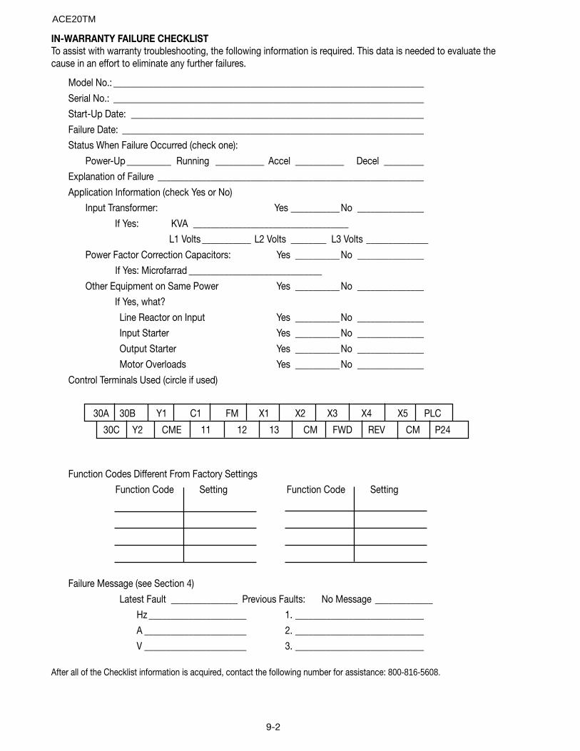
9-2
IN-WARRANTY FAILURE CHECKLISTTo assist with warranty troubleshooting, the following information is required. This data is needed to evaluate thecause in an effort to eliminate any further failures.
Model No.: ______________________________________________________________________
Serial No.: ______________________________________________________________________
Start-Up Date: __________________________________________________________________
Failure Date: ____________________________________________________________________
Status When Failure Occurred (check one):
Power-Up __________ Running ___________ Accel ___________ Decel _________
Explanation of Failure ____________________________________________________________
Application Information (check Yes or No)
Input Transformer: Yes ___________No _______________
If Yes: KVA ___________________________________
L1 Volts ___________ L2 Volts ________ L3 Volts ______________
Power Factor Correction Capacitors: Yes __________No _______________
If Yes: Microfarrad ______________________________
Other Equipment on Same Power Yes __________No _______________
If Yes, what?
Line Reactor on Input Yes __________No _______________
Input Starter Yes __________No _______________
Output Starter Yes __________No _______________
Motor Overloads Yes __________No _______________
Control Terminals Used (circle if used)
Function Codes Different From Factory Settings
Function Code Setting Function Code Setting
Failure Message (see Section 4)
Latest Fault _______________ Previous Faults: No Message _____________
Hz ______________________ 1. _____________________________
A _______________________ 2. _____________________________
V _______________________ 3. _____________________________
After all of the Checklist information is acquired, contact the following number for assistance: 800-816-5608.
30C Y2 CME 11 12 13 CM FWD REV CM P24
30A 30B Y1 C1 FM X1 X2 X3 X4 X5 PLC
ACE20TM
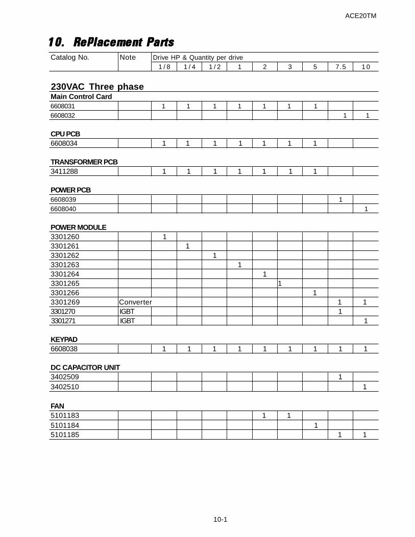
ACE20TM
10-1
10.10.10.10.10. Replacement PartsReplacement PartsReplacement PartsReplacement PartsReplacement PartsCatalog No. Note Drive HP & Quantity per drive
1 / 8 1 / 4 1 / 2 1 2 3 5 7.5 1 0
230VAC Three phase Main Control Card6608031 1 1 1 1 1 1 16608032 1 1
CPU PCB6608034 1 1 1 1 1 1 1
TRANSFORMER PCB3411288 1 1 1 1 1 1 1
POWER PCB6608039 16608040 1
POWER MODULE3301260 13301261 1 3301262 13301263 13301264 13301265 13301266 13301269 Converter 1 13301270 IGBT 13301271 IGBT 1
KEYPAD 6608038
1 1 1 1 1 1 1 1 1
DC CAPACITOR UNIT3402509 13402510 1
FAN5101183 1 15101184 15101185 1 1
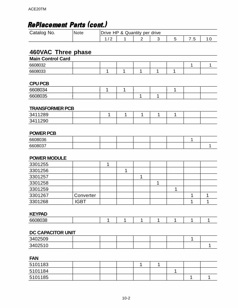
ACE20TM
10-2
Replacement Parts (cont.)Replacement Parts (cont.)Replacement Parts (cont.)Replacement Parts (cont.)Replacement Parts (cont.)Catalog No. Note Drive HP & Quantity per drive
1 / 2 1 2 3 5 7.5 1 0
460VAC Three phase Main Control Card6608032 1 16608033''''''''B 1 1 1 1 1
CPU PCB6608034 =========-1=====-1==================16608035==================================-1=====-1
TRANSFORMER PCB3411289 1 1 1 1 13411290
POWER PCB6608036 16608037 1
POWER MODULE3301255 13301256 13301257 13301258 13301259 13301267 Converter 1 13301268 IGBT 1 1
KEYPAD 6608038
1 1 1 1 1 1 1
DC CAPACITOR UNIT3402509 13402510 1
FAN5101183 1 1 5101184 15101185 1 1
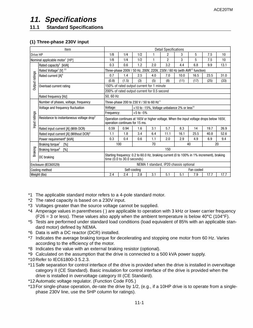
11. Specifications11.1 Standard Specifications
(1) Three-phase 230V input
1/8 1/4 1/2 1 2 3 5 7.5 101/8 1/4 1/2 1 2 3 5 7.5 10
Rated capacity2 [kVA] 0.3 0.6 1.2 2.0 3.2 4.4 6.8 9.9 13.1
Rated Voltage3 [V]Rated current [A]4 0.7 1.4 2.5 4.0 7.0 10.0 16.5 23.5 31.0
(0.8) (1.5) (3) (5) (8) (11) (17) (25) (33)
Overload current rating
Rated frequency [Hz]
Number of phases, voltage, frequency
Voltage and frequency fluctuation
Resistance to instantaneous voltage drop5
Rated input current [A] (With DCR) 0.59 0.94 1.6 3.1 5.7 8.3 14 19.7 26.9
Rated input current [A] (Without DCR)9 1.1 1.8 3.4 6.4 11.1 16.1 25.5 40.8 52.6
Power requirement6 [kVA] 0.3 0.4 0.6 1.1 2.0 2.9 4.9 6.9 9.4
Braking torque7 [%]Braking torque8 [%]
DC braking
2.4 2.4 2.8 3.1 5.1 5.1 7.9 17.7 17.7
150
Brak
ing
Inpu
t rat
ings
Starting frequency: 0.2 to 60.0 Hz, braking current (0 to 100% in 1% increment), braking time (0.0 to 30.0 seconds)
Three-phase 200 to 230 V / 50 to 60 Hz11
Voltage:Frequency:
+10 to -15%, Voltage unbalance 2% or less10
+5 to -5%
Operation continues at 165V or higher voltage. When the input voltage drops below 165V, operation continues for 15 ms.
100 70 40 20
Enclosure (IEC60529)Cooling method
NEMA 1 standard, IP20 chassis optionalFan cooledSelf-cooling
Weight (lbs)
Item Detail Specifications
Three-phase 200V / 50 Hz, 200V, 220V, 230V / 60 Hz (with AVR12 function)
150% of rated output current for 1 minute
Drive HP
Outp
ut ra
tings
Nominal applicable motor1 [HP]
200% of rated output current for 0.5 second50, 60 Hz
ACE20TM
*1 The applicable standard motor refers to a 4-pole standard motor.*2 The rated capacity is based on a 230V input.*3 Voltages greater than the source voltage cannot be supplied.*4 Amperage values in parentheses ( ) are applicable to operation with 3 kHz or lower carrier frequency
(F26 = 3 or less). These values also apply when the ambient temperature is below 40°C (104°F).*5 Tests are performed under standard load conditions (load equivalent of 85% with an applicable stan-
dard motor) defined by NEMA.*6 Data is with a DC reactor (DCR) installed.*7 Indicates the average braking torque for decelerating and stopping one motor from 60 Hz. Varies
according to the efficiency of the motor.*8 Indicates the value with an external braking resistor (optional).*9 Calculated on the assumption that the drive is connected to a 500 kVA power supply.*10 Refer to IEC61800-3 5.2.3.*11 Safe separation for control interface of the drive is provided when the drive is installed in overvoltage
category II (CE Standard). Basic insulation for control interface of the drive is provided when the drive is installed in overvoltage category III (CE Standard).
*12 Automatic voltage regulator. (Function Code F05.)*13 For single-phase operation, de-rate the drive by 1/2, (e.g., if a 10HP drive is to operate from a single-
phase 230V line, use the 5HP column for ratings).
11-1
13
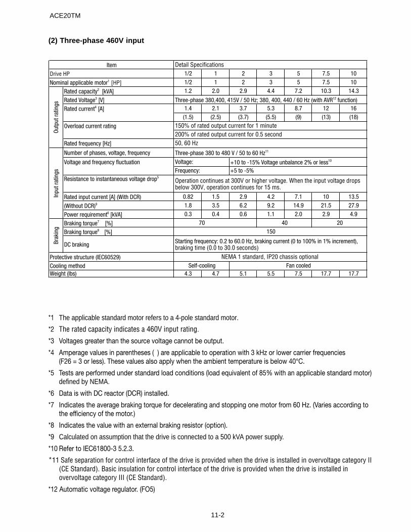
11-2
(2) Three-phase 460V input
1/2 1 2 3 5 7.5 101/2 1 2 3 5 7.5 10
Rated capacity2 [kVA] 1.2 2.0 2.9 4.4 7.2 10.3 14.3
Rated Voltage3 [V]Rated current4 [A] 1.4 2.1 3.7 5.3 8.7 12 16
(1.5) (2.5) (3.7) (5.5) (9) (13) (18)
Overload current rating
Rated frequency [Hz]
Number of phases, voltage, frequency
Voltage and frequency fluctuation+5 to -5%
Resistance to instantaneous voltage drop5
Rated input current [A] (With DCR) 0.82 1.5 2.9 4.2 7.1 10 13.5
(Without DCR)9 1.8 3.5 6.2 9.2 14.9 21.5 27.9
Power requirement6 [kVA] 0.3 0.4 0.6 1.1 2.0 2.9 4.9
Braking torque7 [%]Braking torque8 [%]
DC braking
Weight (lbs) 4.3 4.7 5.1 5.5 7.5 17.7 17.7
200% of rated output current for 0.5 second
NEMA 1 standard, IP20 chassis optional
50, 60 Hz
Three-phase 380 to 480 V / 50 to 60 Hz11
+10 to -15% Voltage unbalance 2% or less10
Operation continues at 300V or higher voltage. When the input voltage drops below 300V, operation continues for 15 ms.
40150
Self-coolingProtective structure (IEC60529)Cooling method
70
Brak
ing
Starting frequency: 0.2 to 60.0 Hz, braking current (0 to 100% in 1% increment), braking time (0.0 to 30.0 seconds)
20
Fan cooled
ItemDrive HP
Voltage:Frequency:
Outp
ut ra
tings
Nominal applicable motor1 [HP]
Inpu
t rat
ings
Detail Specifications
Three-phase 380,400, 415V / 50 Hz; 380, 400, 440 / 60 Hz (with AVR12 function)
150% of rated output current for 1 minute
*1 The applicable standard motor refers to a 4-pole standard motor.
*2 The rated capacity indicates a 460V input rating.
*3 Voltages greater than the source voltage cannot be output.
*4 Amperage values in parentheses ( ) are applicable to operation with 3 kHz or lower carrier frequencies(F26 = 3 or less). These values also apply when the ambient temperature is below 40°C.
*5 Tests are performed under standard load conditions (load equivalent of 85% with an applicable standard motor)defined by NEMA.
*6 Data is with DC reactor (DCR) installed.
*7 Indicates the average braking torque for decelerating and stopping one motor from 60 Hz. (Varies according tothe efficiency of the motor.)
*8 Indicates the value with an external braking resistor (option).
*9 Calculated on assumption that the drive is connected to a 500 kVA power supply.
*10 Refer to IEC61800-3 5.2.3.
*11 Safe separation for control interface of the drive is provided when the drive is installed in overvoltage category II(CE Standard). Basic insulation for control interface of the drive is provided when the drive is installed inovervoltage category III (CE Standard).
*12 Automatic voltage regulator. (FO5)
ACE20TM
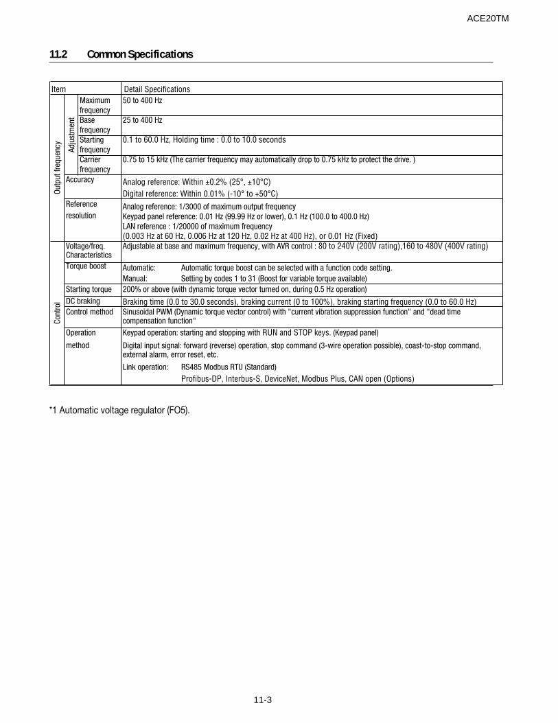
11-3
11.2 Common Specifications
Maximum 50 to 400 HzfrequencyBase 25 to 400 HzfrequencyStarting 0.1 to 60.0 Hz, Holding time : 0.0 to 10.0 seconds frequencyCarrier 0.75 to 15 kHz (The carrier frequency may automatically drop to 0.75 kHz to protect the drive. )frequency
resolution
Automatic: Automatic torque boost can be selected with a function code setting. Manual: Setting by codes 1 to 31 (Boost for variable torque available)
Operation
method
Link operation: RS485 Modbus RTU (Standard) Profibus-DP, Interbus-S, DeviceNet, Modbus Plus, CAN open (Options)
Reference
Voltage/freq. CharacteristicsTorque boost
Starting torque
Digital input signal: forward (reverse) operation, stop command (3-wire operation possible), coast-to-stop command, external alarm, error reset, etc.
200% or above (with dynamic torque vector turned on, during 0.5 Hz operation)
Braking time (0.0 to 30.0 seconds), braking current (0 to 100%), braking starting frequency (0.0 to 60.0 Hz)
Outp
ut fr
eque
ncy
Adjustable at base and maximum frequency, with AVR control : 80 to 240V (200V rating),160 to 480V (400V rating)
DC brakingControl method
Analog reference: Within ±0.2% (25°, ±10°C)Digital reference: Within 0.01% (-10° to +50°C)
Cont
rol
Item Detail Specifications
Sinusoidal PWM (Dynamic torque vector control) with "current vibration suppression function" and "dead time compensation function"Keypad operation: starting and stopping with RUN and STOP keys. (Keypad panel)
Analog reference: 1/3000 of maximum output frequencyKeypad panel reference: 0.01 Hz (99.99 Hz or lower), 0.1 Hz (100.0 to 400.0 Hz)LAN reference : 1/20000 of maximum frequency (0.003 Hz at 60 Hz, 0.006 Hz at 120 Hz, 0.02 Hz at 400 Hz), or 0.01 Hz (Fixed)
Adju
stm
ent
Accuracy
*1 Automatic voltage regulator (FO5).
ACE20TM
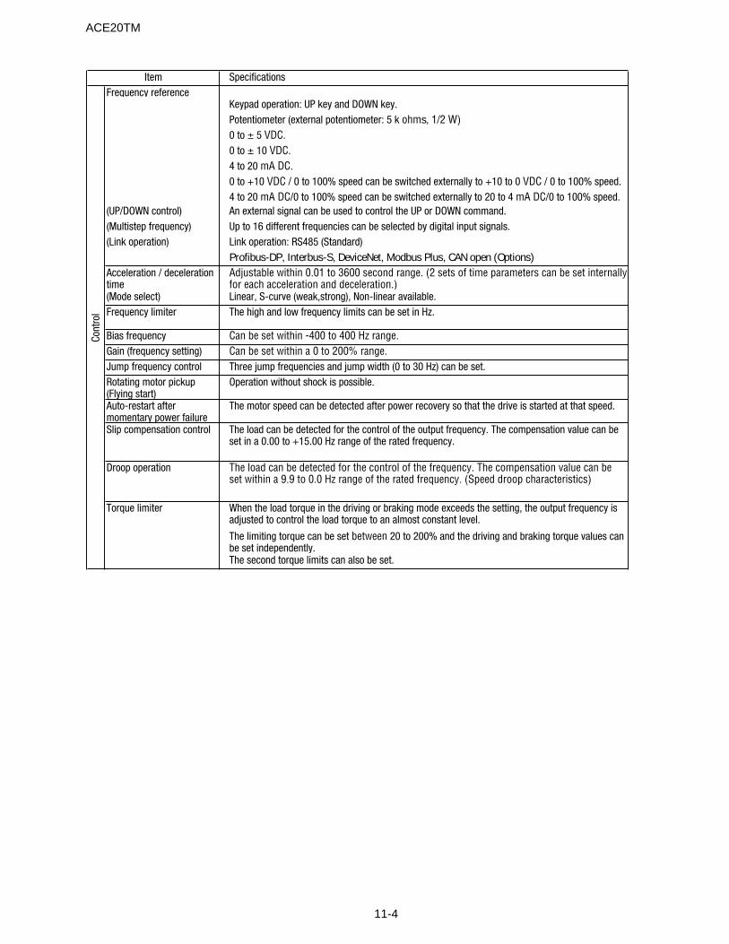
11-4
Frequency reference
(UP/DOWN control)(Multistep frequency)(Link operation)
Profibus-DP, Interbus-S, DeviceNet, Modbus Plus, CAN open (Options)Acceleration / deceleration time(Mode select)Frequency limiter
Bias frequencyGain (frequency setting)Jump frequency controlRotating motor pickup (Flying start)Auto-restart after momentary power failureSlip compensation control
Droop operation
Torque limiter
Cont
rol
Item
Link operation: RS485 (Standard)
Specifications
The limiting torque can be set between 20 to 200% and the driving and braking torque values can be set independently.The second torque limits can also be set.
Keypad operation: UP key and DOWN key.Potentiometer (external potentiometer: 5 k ohms, 1/2 W)0 to ± 5 VDC.0 to ± 10 VDC.
The load can be detected for the control of the output frequency. The compensation value can be set in a 0.00 to +15.00 Hz range of the rated frequency.
The load can be detected for the control of the frequency. The compensation value can beset within a 9.9 to 0.0 Hz range of the rated frequency. (Speed droop characteristics)
When the load torque in the driving or braking mode exceeds the setting, the output frequency is adjusted to control the load torque to an almost constant level.
4 to 20 mA DC.0 to +10 VDC / 0 to 100% speed can be switched externally to +10 to 0 VDC / 0 to 100% speed.
An external signal can be used to control the UP or DOWN command.Up to 16 different frequencies can be selected by digital input signals.
4 to 20 mA DC/0 to 100% speed can be switched externally to 20 to 4 mA DC/0 to 100% speed.
Can be set within a 0 to 200% range.Three jump frequencies and jump width (0 to 30 Hz) can be set.Operation without shock is possible.
The motor speed can be detected after power recovery so that the drive is started at that speed.
Adjustable within 0.01 to 3600 second range. (2 sets of time parameters can be set internallyfor each acceleration and deceleration.)
The high and low frequency limits can be set in Hz.Linear, S-curve (weak,strong), Non-linear available.
Can be set within -400 to 400 Hz range.
ACE20TM

11-5
Item SpecificationsPID control This function can control flow rate, pressure, etc. with analog feedback signal.
The reference and feedback values are displayed in %.
Reference signal
Keypad operation UP key and DOWN key. : 0.0 to 100%
Voltage input (Terminal 12) : 0 to 10 VDCCurrent input (Terminal C1) : 4 to 20 mA DCMultistep frequency setting : Setting freq./max. freq. x 100%RS485 : Setting freq./max. freq. x 100%Feedback signal
Terminal 12 (0 to +10Vdc or +10 to 0Vdc)
Terminal C1(4 to 20mAdc or 20 to 4mAdcSecond motor’s setting
Energy saving operationDuring operation/stop The keypad panel can be extended. (Optional 5 meter extension cable is available.)
7-segment LED display items
• Set frequency • Output frequency
• Output current • Motor RPM• Output voltage • Line speed
• PID setting/feedback values
(A soft filter is provided to attenuate the fluctuation in the displayed value.)
A charge lamp indicates the power supply is energized.When setting The function code and data code are displayed.
When tripped [The cause of trip is displayed.]
• OC1 (overcurrent: during acceleration)
• OC2 (overcurrent: during deceleration)
• OC3 (overcurrent: during constant speed operation)
• OU1 (overvoltage: during acceleration)
• OU2 (overvoltage: during deceleration)
• OU3 (overvoltage: during constant speed operation)
• LU (undervoltage)
• Lin (input phase loss)
• dbH (external braking resistor overheated (thermal overload relay))
• OH1 (overheat: heat sink)
• OH2 (overheat: external thermal overload relay)
• OL1 (overload: motor 1)
• OL2 (overload: motor 2)
• OLU (overload: drive)
• Er1 (memory error)
• Er2 (keypad panel communication error)
• Er3 (CPU error)
• Er4 (option error)
• Er5 (option error)
• Er6 (operating error)
• Er7 (output wiring error) (impedance imbalance)
• Er8 (RS485 communication error)During operation, when tripped The last four records of trip history are stored and displayed.
Disp
lay
Cont
rol
The V/f pattern of the second motor can be selected with an external signal.The motor constants of the second motor can be set with an external signal.
The electronic thermal overload relay of the second motor can be internally set for selection with an external signal.
Weak magnetic flux can be set for light loads which allows operation with an increased motor efficiency.
ACE20TM
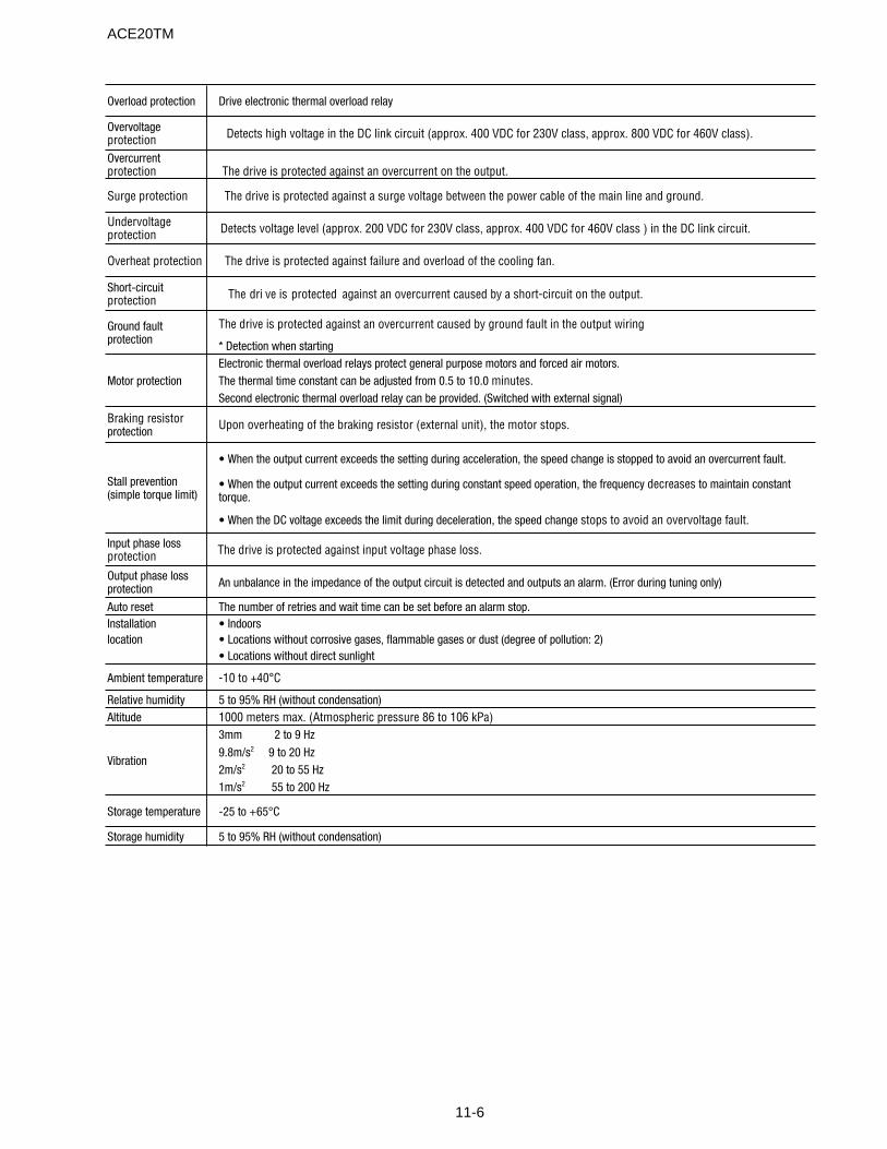
11-6
Overload protection Drive electronic thermal overload relay
Overvoltage protection Detects high voltage in the DC link circuit (approx. 400 VDC for 230V class, approx. 800 VDC for 460V class).
Overcurrent protection The drive is protected against an overcurrent on the output.
Surge protection The drive is protected against a surge voltage between the power cable of the main line and ground.
Undervoltage protection Detects voltage level (approx. 200 VDC for 230V class, approx. 400 VDC for 460V class ) in the DC link circuit.
Overheat protection The drive is protected against failure and overload of the cooling fan.
Short-circuit protection The dri ve is protected against an overcurrent caused by a short-circuit on the output.
The drive is protected against an overcurrent caused by ground fault in the output wiring.
* Detection when startingElectronic thermal overload relays protect general purpose motors and forced air motors.The thermal time constant can be adjusted from 0.5 to 10.0 minutes.Second electronic thermal overload relay can be provided. (Switched with external signal)
Braking resistor protection Upon overheating of the braking resistor (external unit), the motor stops.
• When the output current exceeds the setting during acceleration, the speed change is stopped to avoid an overcurrent fault.
• When the output current exceeds the setting during constant speed operation, the frequency decreases to maintain constant torque.
• When the DC voltage exceeds the limit during deceleration, the speed change stops to avoid an overvoltage fault.
Input phase loss protection The drive is protected against input voltage phase loss.
Output phase loss protection An unbalance in the impedance of the output circuit is detected and outputs an alarm. (Error during tuning only)
Auto reset The number of retries and wait time can be set before an alarm stop.Installation • Indoorslocation • Locations without corrosive gases, flammable gases or dust (degree of pollution: 2)
• Locations without direct sunlight
Ambient temperature -10 to +40°C
Relative humidity 5 to 95% RH (without condensation)Altitude 1000 meters max. (Atmospheric pressure 86 to 106 kPa)
3mm 2 to 9 Hz
9.8m/s2 9 to 20 Hz2m/s2 20 to 55 Hz1m/s2 55 to 200 Hz
Storage temperature -25 to +65°C
Storage humidity 5 to 95% RH (without condensation)
Ground fault protection
Motor protection
Stall prevention (simple torque limit)
Vibration
ACE20TM
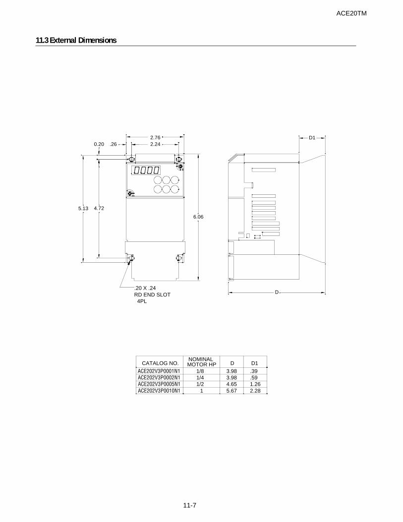
11-7
11.3 External Dimensions
ACE20TM
.26 2.242.76
0.20
4.725.13
6.06
.20 X .24RD END SLOT 4PL
D1
D
NOMINALMOTOR HP
ACE202V3P0002N1
ACE202V3P0010N1ACE202V3P0005N1
ACE202V3P0001N1CATALOG NO.
1/21
1/41/8
4.655.67
3.983.98
D
2.281.26.59.39
D1
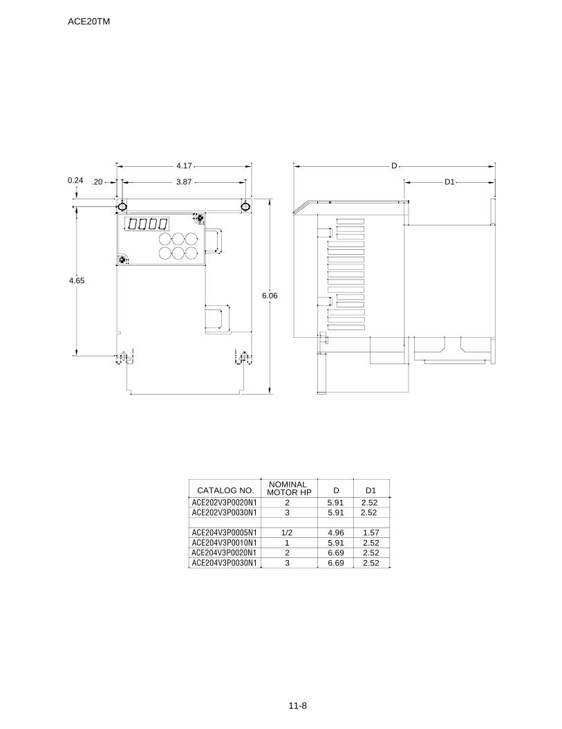
11-8
ACE20TM
D
D13.87.20
4.17
4.65
0.24
6.06
ACE202V3P0020N1 5.91 2.52ACE202V3P0030N1 5.91 2.52
ACE204V3P0005N1 4.96 1.57ACE204V3P0010N1 5.91 2.52ACE204V3P0020N1 6.69 2.52ACE204V3P0030N1 6.69 2.52
D D1CATALOG NO.NOMINALMOTOR HP
23
1/2123
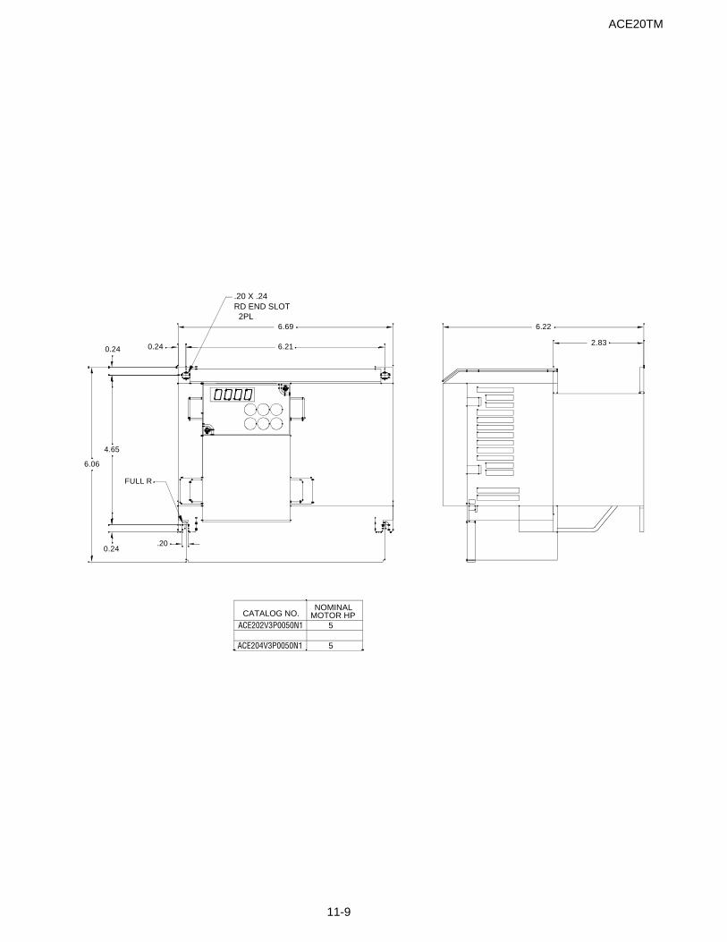
11-9
ACE20TM
6.210.24
4.65
6.06
6.69
.20
2.83
6.22
.20 X .24RD END SLOT 2PL
0.24
FULL R
0.24
ACE202V3P0050N1CATALOG NO.
ACE204V3P0050N1
NOMINALMOTOR HP
5
5
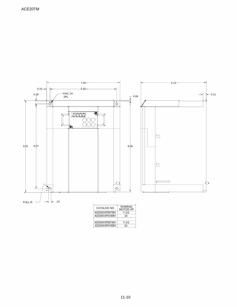
11-10
ACE20TM
6.460.31
7.00
8.07
0.28
8.81 8.66
0.31
6.22
0.06
.24FULL R
%%C.242PL
ACE202V3P0075N1ACE202V3P0100N1
CATALOG NO.
ACE204V3P0075N1ACE204V3P0100N1 10
7-1/2
107-1/2
NOMINALMOTOR HP
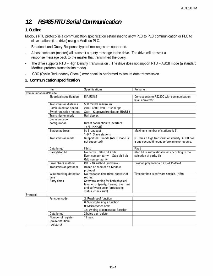
12-1
12. RS485 RTU Serial Communication1. OutlineModbus RTU protocol is a communication specification established to allow PLC to PLC communication or PLC to
slave stations (i.e., drive) using a Modicon PLC.
- Broadcast and Query-Response type of messages are supported.
- A host computer (master) will transmit a query message to the drive. The drive will transmit aresponse message back to the master that transmitted the query.
- The drive supports RTU – High Density Transmission . The drive does not support RTU – ASCII mode (a standardModbus protocol transmission mode).
- CRC (Cyclic Redundancy Check ) error check is performed to secure data transmission.
2. Communication specification
Item Specifications Remarks
Electrical specification EIA RS485 Corresponds to RS232C with communication level converter
Transmission distance 500 meters maximumCommunication speed 2400, 4800, 9600, 19200 bpsSynchronization method Start - Stop synchronization (UART )Transmission mode Half duplexCommunicationconfiguration Direct connection to inverters
1 : N (1≤N≤31)Station address 0 : Broadcast Maximum number of stations is 31
1-247 : Slave stationsTransmission mode Supports RTU mode (ASCII mode is
not supported)RTU has a high transmission density. ASCII has a one second timeout before an error occurs.
Data length 8 bits FixedParity/stop bit No parity Stop bit 2 bits
Even number parity Stop bit 1 bitOdd number parity
Error check method CRC - 16 method (software ) Created polynominal : X16+X15+X2+1Transmission protocol Based on Modicon's Modbus
protocolWire breaking detection time
No response time (time-out) x (# of retries)
Timeout time is software setable. (H39)
Retry times Software setting for both physical layer error (parity, framing, overrun) and software error (processing status, check sum)
Function code 3: Reading of function6: Writing to single function8: Maintenance code16: Writing to continuous function
Data length 2 bytes per registerNumber of register 16 max.(preset multiple registers)
Stop bit is automatically set according to the selection of parity bit
Protocol
Communication (PC side )
ACE20TM
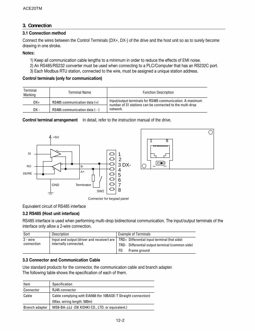
12-2
3. Connection3.1 Connection method
Connect the wires between the Control Terminals (DX+, DX-) of the drive and the host unit so as to surely becomedrawing in one stroke.
Notes:
1) Keep all communication cable lengths to a minimum in order to reduce the effects of EMI noise.2) An RS485/RS232 converter must be used when connecting to a PLC/Computer that has an RS232C port.3) Each Modbus RTU station, connected to the wire, must be assigned a unique station address.
Control terminals (only for communication)
TerminalMarking
DX+ RS485 communication data (+)
DX - RS485 communication data ( - )
Input/output terminals for RS485 communication. A maximum number of 31 stations can be connected to the multi-drop network.
Terminal Name Function Description
Control terminal arrangement In detail, refer to the instruction manual of the drive.
12
45678
3 DX-
GND
+5V
B-
A+
DI
RO
DE/RE
Terminator
SW2
Connector for keypad panel
1 8
ON OFFS
W2
Equivalent circuit of RS485 interface
3.2 RS485 (Host unit interface)
RS485 interface is used when performing multi-drop bidirectional communication. The input/output terminals of theinterface only allow a 2-wire connection.
Sort Description Example of TerminalsTRD+ Differential input terminal (hot side)TRD- Differential output terminal (common side)FG Frame ground
2 - wire connection
Input and output (driver and receiver) are internally connected.
3.3 Connector and Communication Cable
Use standard products for the connector, the communication cable and branch adapter.The following table shows the specification of each of them.
Item SpecificationConnector RJ45 connectorCable Cable complying with EIA568 (for 10BASE-T Straight connection)
(Max. wiring length: 500m)Branch adapter MS8-BA-JJJ (SK KOHKI CO., LTD. or equivalent.)
ACE20TM
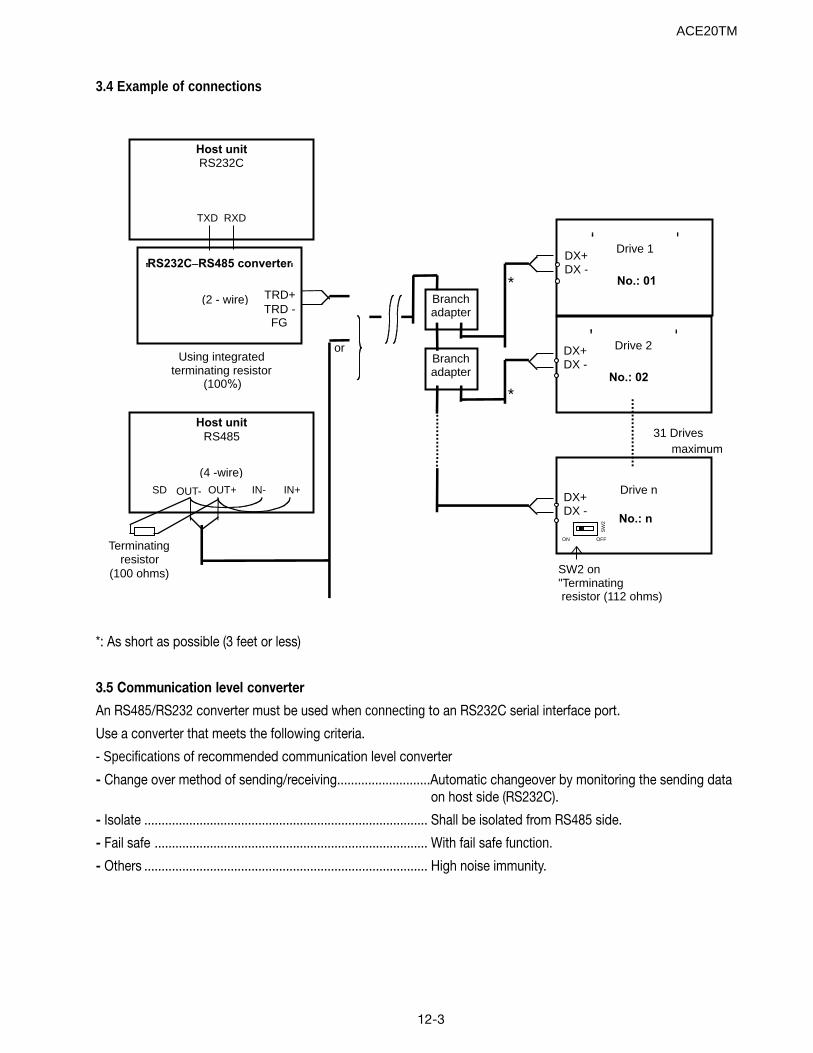
12-3
Host unit
RS232C
TXD RXD
Host unit
RS485
SD OUT- OUT+ IN- IN+
RS232C_RS485 converter
TRD+TRD -
FG
Terminatingresistor
(100 ohms)
(4 -wire)
(2 - wire)
Using integratedterminating resistor
(100%)
31 Drivesmaximum
SW2 on"Terminating resistor (112 ohms)
Drive nDX+DX -
No.: n
Drive 2DX+DX -
No.: 02
Drive 1DX+DX -
No.: 01
Branchadapter
Branchadapter
ON OFF
SW
2
*
or
*
3.4 Example of connections
*: As short as possible (3 feet or less)
3.5 Communication level converter
An RS485/RS232 converter must be used when connecting to an RS232C serial interface port.
Use a converter that meets the following criteria.
- Specifications of recommended communication level converter
- Change over method of sending/receiving...........................Automatic changeover by monitoring the sending dataon host side (RS232C).
- Isolate .................................................................................. Shall be isolated from RS485 side.
- Fail safe ............................................................................... With fail safe function.
- Others .................................................................................. High noise immunity.
ACE20TM
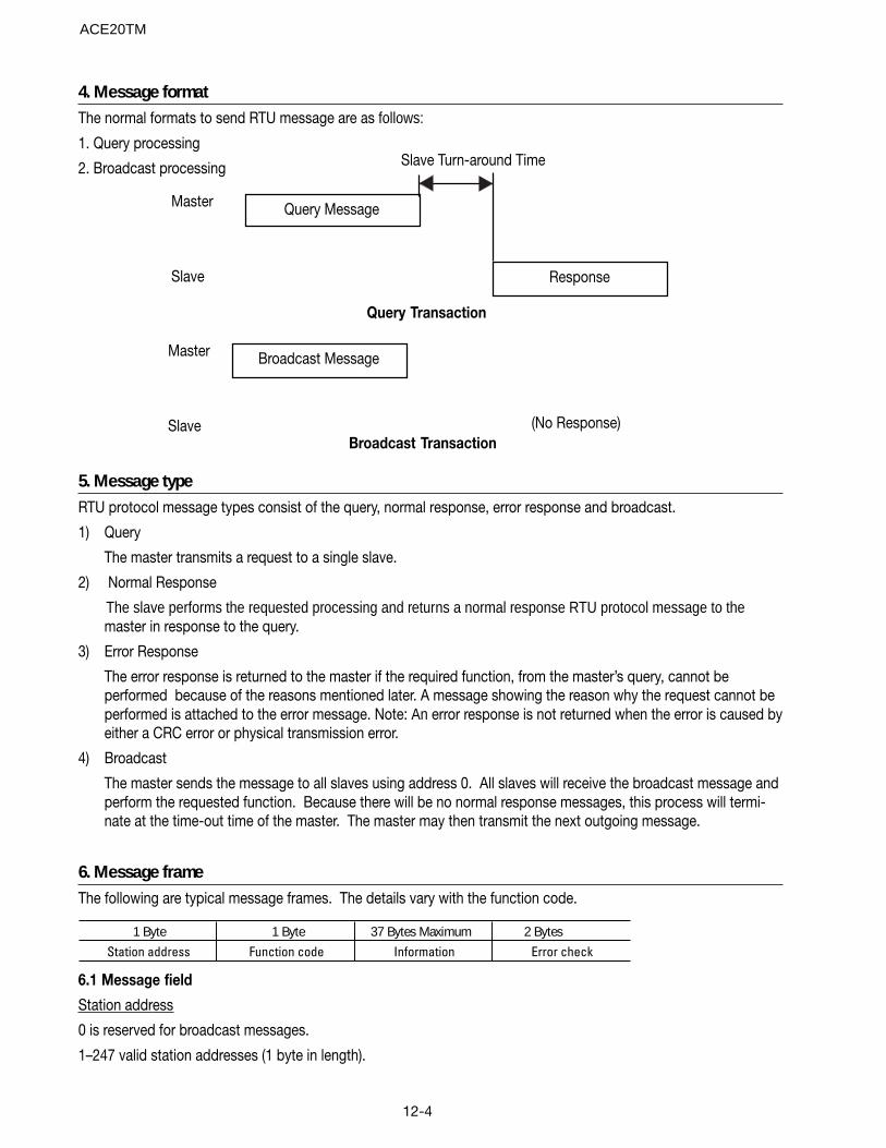
12-4
4. Message formatThe normal formats to send RTU message are as follows:
1. Query processing
2. Broadcast processing
Query Message
Broadcast Message
Response
Slave Turn-around Time
Master
Slave
Master
Slave (No Response)
Query Transaction
Broadcast Transaction
5. Message typeRTU protocol message types consist of the query, normal response, error response and broadcast.
1) Query
The master transmits a request to a single slave.
2) Normal Response
The slave performs the requested processing and returns a normal response RTU protocol message to themaster in response to the query.
3) Error Response
The error response is returned to the master if the required function, from the master’s query, cannot beperformed because of the reasons mentioned later. A message showing the reason why the request cannot beperformed is attached to the error message. Note: An error response is not returned when the error is caused byeither a CRC error or physical transmission error.
4) Broadcast
The master sends the message to all slaves using address 0. All slaves will receive the broadcast message andperform the requested function. Because there will be no normal response messages, this process will termi-nate at the time-out time of the master. The master may then transmit the next outgoing message.
6. Message frameThe following are typical message frames. The details vary with the function code.
1 Byte 1 Byte 37 Bytes Maximum 2 BytesStation address Function code Information Error check
6.1 Message field
Station address
0 is reserved for broadcast messages.
1–247 valid station addresses (1 byte in length).
ACE20TM

12-5
Function Code (FC )
The Function Code is a single byte parameter. The following table shows thefunction codes used by the drive.
FC: There are two function codes mentioned in this manual. One is the Modbus RTU message function codewhich will be referred to as “FC." The second is the drive parameter function codes.
FC Description0_2 Not used
3 Reading of function4_5 Not used
6 Writing to single function7 Not used8 Maintenance code
9_15 Not used16 Writing to continuous function (maximum 16 data)
17_127 Not used128_255 Reserved for exception response
Information
Refer to Section “8. Sort of Messages” (see page 12-9) for detailed specification of the information field for eachmessage type (broadcast, query, normal response and error response).
Error Check
The error check field is 2 bytes length data of CRC - 16 checksum. As for details of CRC - 16 calculation oralgorithm, refer to Åg7. CRC - 16Åh.
Since the information field length is variable, the frame length necessary to calculate CRC - 16 code from FC andbyte count data. As for byte count, refer to Åg8. Sort of MessageÅh.
6.2 Character format
Each byte of a message is called a character. The character formats are shown below.
A character is configured with a start bit (logic 0), 8-data bits, addition of parity bit (selection) and stop bit (logic1).
Without parity
LSB MSB0 1 2 3 4 5 6 7 8
Start Data
9 10
Stop
With Parity
LSB MSB0 1 2 3 4 5 6 7 8 9 10
Start Data Parity (optional ) Stop
ACE20TM
12-6
7. CRC - 16CRC (Cyclic Redundancy Check) is one of the most effective checksum algorithyms used today to verify messagedata integrity. The transmitting station calculates a CRC and adds the CRC (2 bytes in length) to the last frame. Thereceiving station also calculates a CRC for the received data and compares the calculated to the received CRC. Ifthe two CRC’s agree, then the message is accepted.
The short description of calculating a CRC is as follows.
- The data is converted to polynomial form (for example, 1100 0000 0010 0001ÆX15+X14+X5+1) is divided by acreated polynomial (17bitÅF X16+X15+X2+1). CRC is the remainder (16 bits) of this division.
- The quotient is neglected. The remainder is sent as the CRC-16.
- The receiving side divides this message (added CRC) by the created polynomial, and considers the transmis-sion complete and correct when the remainder is 0.
The created polynomial represents the data algebraically with exponent of X such as X3+X2+X, instead of descriptionsuch as a binary code 1101. The created polynomial is allowed any length and any bit patterns, but several standardcreated polynomials are defined to optimize the error detection. In RTU protocol, the created polynomial(X16+X15+X2+1) that is binary 1 1000 0000 0000 0101 is used. In this case the created CRC is known as CRC-16.
ACE20TM
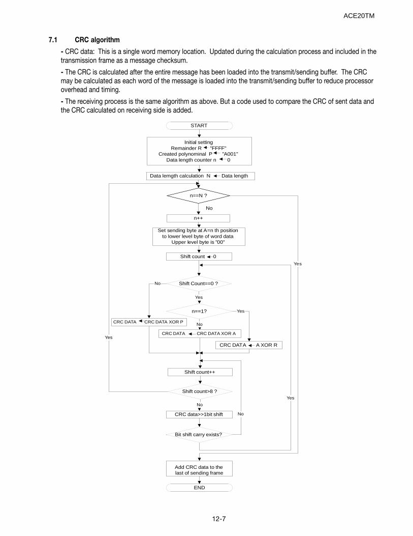
12-7
7.1 CRC algorithm
- CRC data: This is a single word memory location. Updated during the calculation process and included in thetransmission frame as a message checksum.
- The CRC is calculated after the entire message has been loaded into the transmit/sending buffer. The CRCmay be calculated as each word of the message is loaded into the transmit/sending buffer to reduce processoroverhead and timing.
- The receiving process is the same algorithm as above. But a code used to compare the CRC of sent data andthe CRC calculated on receiving side is added.
Initial settingRemainder R "FFFF"
Created polynominal P "A001"Data length counter n 0
n==N ?
n++
Set sending byte at A=n th positionto lower level byte of word data
Upper level byte is "00"
CRC DATA CRC DATA XOR A
Shift count>8 ?
Shift count++
Yes
Bit shift carry exists?
No
CRC DATA CRC DATA XOR P
Shift Count==0 ?
Yes
No
Shift count 0
Yes
Add CRC data to the last of sending frame
END
START
Yes
n==1?
CRC DATA A XOR R
No
Yes
No
CRC data>>1bit shift
Data lemgth calculation N Data length
No
ACE20TM
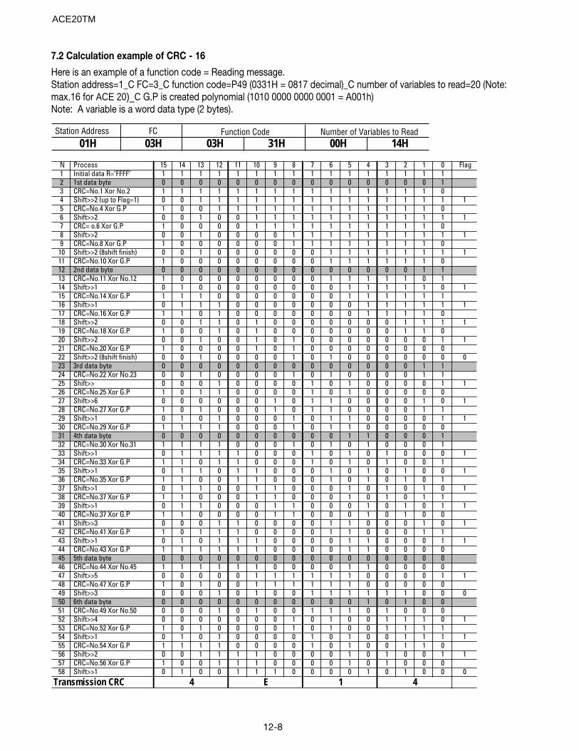
12-8
7.2 Calculation example of CRC - 16
Here is an example of a function code = Reading message.Station address=1_C FC=3_C function code=P49 (0331H = 0817 decimal)_C number of variables to read=20 (Note:max.16 for ACE 20)_C G.P is created polynomial (1010 0000 0000 0001 = A001h)Note: A variable is a word data type (2 bytes).
Station Address FC 01H 03H 03H 31H 00H 14H
Function Code Number of Variables to Read
N Process 15 14 13 12 11 10 9 8 7 6 5 4 3 2 1 0 Flag1 Initial data R="FFFF" 1 1 1 1 1 1 1 1 1 1 1 1 1 1 1 1 2 1st data byte 0 0 0 0 0 0 0 0 0 0 0 0 0 0 0 1 3 CRC=No.1 Xor No.2 1 1 1 1 1 1 1 1 1 1 1 1 1 1 1 0 4 Shift>>2 (up to Flag=1) 0 0 1 1 1 1 1 1 1 1 1 1 1 1 1 1 15 CRC=No.4 Xor G.P 1 0 0 1 1 1 1 1 1 1 1 1 1 1 1 0 6 Shift>>2 0 0 1 0 0 1 1 1 1 1 1 1 1 1 1 1 17 CRC= o.6 Xor G.P 1 0 0 0 0 1 1 1 1 1 1 1 1 1 1 0 8 Shift>>2 0 0 1 0 0 0 0 1 1 1 1 1 1 1 1 1 19 CRC=No.8 Xor G.P 1 0 0 0 0 0 0 1 1 1 1 1 1 1 1 0
10 Shift>>2 (8shift finish) 0 0 1 0 0 0 0 0 0 1 1 1 1 1 1 1 111 CRC=No.10 Xor G.P 1 0 0 0 0 0 0 0 0 1 1 1 1 1 1 0 12 2nd data byte 0 0 0 0 0 0 0 0 0 0 0 0 0 0 1 1 13 CRC=No.11 Xor No.12 1 0 0 0 0 0 0 0 0 1 1 1 1 1 0 1 14 Shift>>1 0 1 0 0 0 0 0 0 0 0 1 1 1 1 1 0 115 CRC=No.14 Xor G.P 1 1 1 0 0 0 0 0 0 0 1 1 1 1 1 1 16 Shift>>1 0 1 1 1 0 0 0 0 0 0 0 1 1 1 1 1 117 CRC=No.16 Xor G.P 1 1 0 1 0 0 0 0 0 0 0 1 1 1 1 0 18 Shift>>2 0 0 1 1 0 1 0 0 0 0 0 0 0 1 1 1 119 CRC=No.18 Xor G.P 1 0 0 1 0 1 0 0 0 0 0 0 0 1 1 0 20 Shift>>2 0 0 1 0 0 1 0 1 0 0 0 0 0 0 0 1 121 CRC=No.20 Xor G.P 1 0 0 0 0 1 0 1 0 0 0 0 0 0 0 0 22 Shift>>2 (8shift finish) 0 0 1 0 0 0 0 1 0 1 0 0 0 0 0 0 023 3rd data byte 0 0 0 0 0 0 0 0 0 0 0 0 0 0 1 1 24 CRC=No.22 Xor No.23 0 0 1 0 0 0 0 1 0 1 0 0 0 0 1 1 25 Shift>> 0 0 0 1 0 0 0 0 1 0 1 0 0 0 0 1 126 CRC=No.25 Xor G.P 1 0 1 1 0 0 0 0 1 0 1 0 0 0 0 0 27 Shift>>6 0 0 0 0 0 0 1 0 1 1 0 0 0 0 1 0 128 CRC=No.27 Xor G.P 1 0 1 0 0 0 1 0 1 1 0 0 0 0 1 1 29 Shift>>1 0 1 0 1 0 0 0 1 0 1 1 0 0 0 0 1 130 CRC=No.29 Xor G.P 1 1 1 1 0 0 0 1 0 1 1 0 0 0 0 0 31 4th data byte 0 0 0 0 0 0 0 0 0 0 1 1 0 0 0 1 32 CRC=No.30 Xor No.31 1 1 1 1 0 0 0 1 0 1 0 1 0 0 0 1 33 Shift>>1 0 1 1 1 1 0 0 0 1 0 1 0 1 0 0 0 134 CRC=No.33 Xor G.P 1 1 0 1 1 0 0 0 1 0 1 0 1 0 0 1 35 Shift>>1 0 1 1 0 1 1 0 0 0 1 0 1 0 1 0 0 136 CRC=No.35 Xor G.P 1 1 0 0 1 1 0 0 0 1 0 1 0 1 0 1 37 Shift>>1 0 1 1 0 0 1 1 0 0 0 1 0 1 0 1 0 138 CRC=No.37 Xor G.P 1 1 0 0 0 1 1 0 0 0 1 0 1 0 1 1 39 Shift>>1 0 1 1 0 0 0 1 1 0 0 0 1 0 1 0 1 140 CRC=No.37 Xor G.P 1 1 0 0 0 0 1 1 0 0 0 1 0 1 0 0 41 Shift>>3 0 0 0 1 1 0 0 0 0 1 1 0 0 0 1 0 142 CRC=No.41 Xor G.P 1 0 1 1 1 0 0 0 0 1 1 0 0 0 1 1 43 Shift>>1 0 1 0 1 1 1 0 0 0 0 1 1 0 0 0 1 144 CRC=No.43 Xor G.P 1 1 1 1 1 1 0 0 0 0 1 1 0 0 0 0 45 5th data byte 0 0 0 0 0 0 0 0 0 0 0 0 0 0 0 0 46 CRC=No.44 Xor No.45 1 1 1 1 1 1 0 0 0 0 1 1 0 0 0 0 47 Shift>>5 0 0 0 0 0 1 1 1 1 1 1 0 0 0 0 1 148 CRC=No.47 Xor G.P 1 0 1 0 0 1 1 1 1 1 1 0 0 0 0 0 49 Shift>>3 0 0 0 1 0 1 0 0 1 1 1 1 1 1 0 0 050 6th data byte 0 0 0 0 0 0 0 0 0 0 0 1 0 1 0 0 51 CRC=No.49 Xor No.50 0 0 0 1 0 1 0 0 1 1 1 0 1 0 0 0 52 Shift>>4 0 0 0 0 0 0 0 1 0 1 0 0 1 1 1 0 153 CRC=No.52 Xor G.P 1 0 1 0 0 0 0 1 0 1 0 0 1 1 1 1 54 Shift>>1 0 1 0 1 0 0 0 0 1 0 1 0 0 1 1 1 155 CRC=No.54 Xor G.P 1 1 1 1 0 0 0 0 1 0 1 0 0 1 1 0 56 Shift>>2 0 0 1 1 1 1 0 0 0 0 1 0 1 0 0 1 157 CRC=No.56 Xor G.P 1 0 0 1 1 1 0 0 0 0 1 0 1 0 0 0 58 Shift>>1 0 1 0 0 1 1 1 0 0 0 0 1 0 1 0 0 0
4Transmission CRC 4 E 1
ACE20TM
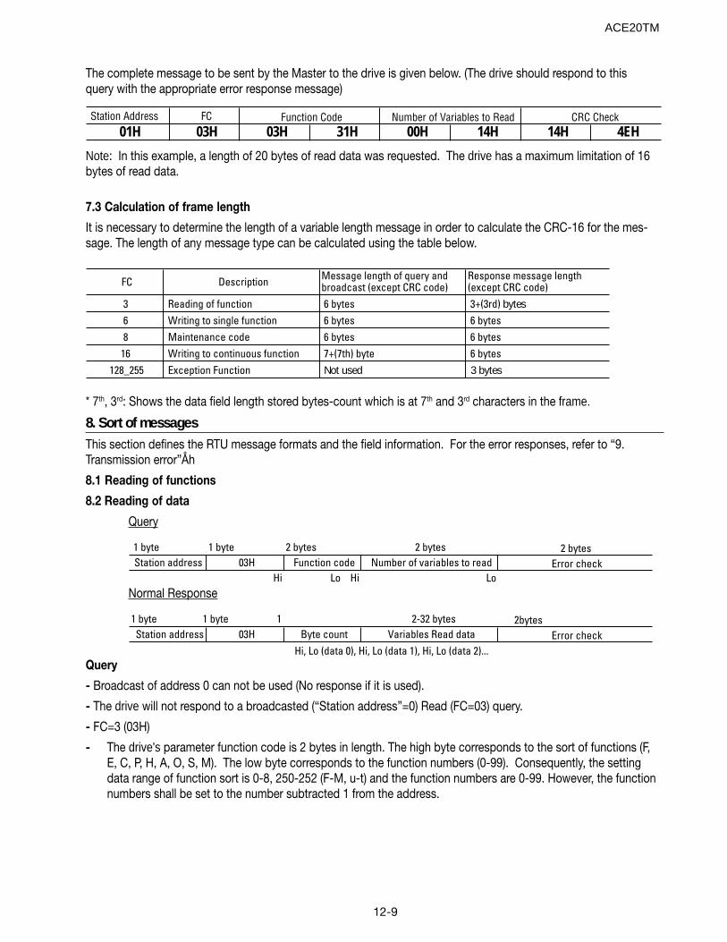
12-9
The complete message to be sent by the Master to the drive is given below. (The drive should respond to thisquery with the appropriate error response message)
Station Address FC 01H 03H 03H 31H 00H 14H 14H 4EH
Function Code Number of Variables to Read CRC Check
Note: In this example, a length of 20 bytes of read data was requested. The drive has a maximum limitation of 16bytes of read data.
7.3 Calculation of frame length
It is necessary to determine the length of a variable length message in order to calculate the CRC-16 for the mes-sage. The length of any message type can be calculated using the table below.
FC Description Message length of query and broadcast (except CRC code)
Response message length (except CRC code)
3 Reading of function 6 bytes 3+(3rd) bytes6 Writing to single function 6 bytes 6 bytes8 Maintenance code 6 bytes 6 bytes
16 Writing to continuous function 7+(7th) byte 6 bytes 128_255 Exception Function Not used 3 bytes
* 7th, 3rd: Shows the data field length stored bytes-count which is at 7th and 3rd characters in the frame.
8. Sort of messagesThis section defines the RTU message formats and the field information. For the error responses, refer to “9.Transmission error”Åh
8.1 Reading of functions
8.2 Reading of data
Query
1 byte 1 byte 2 bytes 2 bytes Station address 03H Function code Number of variables to read
Hi Lo Hi Lo
2 bytes Error check
Normal Response
1 byte 1 byte 1 2-32 bytes Station address 03H Byte count Variables Read data
Hi, Lo (data 0), Hi, Lo (data 1), Hi, Lo (data 2)...
2bytes Error check
Query
- Broadcast of address 0 can not be used (No response if it is used).
- The drive will not respond to a broadcasted (“Station address”=0) Read (FC=03) query.
- FC=3 (03H)
- The drive's parameter function code is 2 bytes in length. The high byte corresponds to the sort of functions (F,E, C, P, H, A, O, S, M). The low byte corresponds to the function numbers (0-99). Consequently, the settingdata range of function sort is 0-8, 250-252 (F-M, u-t) and the function numbers are 0-99. However, the functionnumbers shall be set to the number subtracted 1 from the address.
ACE20TM
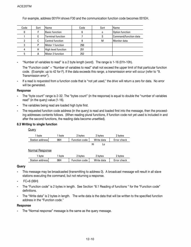
12-10
For example, address 001FH shows F30 and the communication function code becomes 001EH.
Code Sort Name Code Sort Name0 F Basic function 6 o Option function1 E Terminal function 7 S Command/function data2 C Control function 8 M Monitor data3 P Motor 1 function 2504 H High level function 2515 A Motor 2 function 252
- “Number of variables to read” is a 2 byte length (word). The range is 1-16 (01h-10h).
The “Function code” + “Number of variables to read” shall not exceed the upper limit of that particular functioncode. (Example: up to 42 for F). If the data exceeds this range, a transmission error will occur (refer to “9.Transmission error”).
- If a read is requested from a function code that is “not yet used," the drive will return a zero for data. No errorwill be generated.
Response
- The “byte count” range is 2-32. The “bytes count” (in the response) is equal to double the “number of variablesread” (in the query) value (1-16).
- The variables being read are loaded high byte first.
- The requested function code address (in the query) is read and loaded first into the message, then the proceed-ing addresses contents follows. (When reading plural functions, if function code not yet used is included in andafter the second functions, the reading data become unsettled).
8.3 Writing to single function
Query
1 byte 1 byte 2 bytes 2 bytes 2 bytes Station address 06H Function code Write data Error check
Hi Lo
Normal Response
1 byte 1 byte 2 bytes 2 bytes 2 bytes Station address 06H Function code Write data Error check
Query
- This message may be broadcasted (transmitting to address 0). A broadcast message will result in all slavestations executing the command, but not returning a response.
- FC=6 (06H)
- The “Function code” is 2 bytes in length. See Section “8.1 Reading of functions “ for the “Function code”definitions.
- The “Write data” is 2 bytes in length. The write data is the data that will be written to the specified functionaddress in the “Function code."
Response
- The “Normal response” message is the same as the query message.
ACE20TM
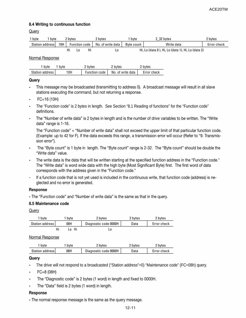
12-11
8.4 Writing to continuous function
Query
1 byte 1 byte 2 bytes 2 bytes 1 byte 2_32 bytes 2 bytes Station address 10H Function code No. of write data Byte count Write data Error check
Hi Lo Hi Lo Hi, Lo (data 0 ), Hi, Lo (data 1), Hi, Lo (data 2)
Normal Response
1 byte 1 byte 2 bytes 2 bytes 2 bytes Station address 10H Function code No. of write data Error check
Query
- This message may be broadcasted (transmitting to address 0). A broadcast message will result in all slavestations executing the command, but not returning a response.
- FC=16 (10H)
- The “Function code” is 2 bytes in length. See Section “8.1 Reading of functions" for the “Function code”definitions.
- The “Number of write data” is 2 bytes in length and is the number of drive variables to be written. The “Writedata” range is 1-16.
The “Function code” + “Number of write data” shall not exceed the upper limit of that particular function code.(Example: up to 42 for F). If the data exceeds this range, a transmission error will occur (Refer to “9. Transmis-sion error”).
- The “Byte count” is 1 byte in length. The “Byte count” range is 2-32. The “Byte count” should be double the“Write data” value.
- The write data is the data that will be written starting at the specified function address in the “Function code."The “Write data” is word wide data with the high byte (Most Significant Byte) first. The first word of datacorresponds with the address given in the “Function code."
- If a function code that is not yet used is included in the continuous write, that function code (address) is ne-glected and no error is generated.
Response
- The “Function code” and “Number of write data” is the same as that in the query.
8.5 Maintenance code
Query
1 byte 1 byte 2 bytes 2 bytes 2 bytes Station address 08H Diagnostic code 0000H Data Error check
Hi Lo Hi Lo
Normal Response
1 byte 1 byte 2 bytes 2 bytes 2 bytes Station address 08H Diagnostic code 0000H Data Error check
Query
- The drive will not respond to a broadcasted (“Station address”=0) “Maintenance code” (FC=08h) query.
- FC=8 (08H)
- The “Diagnostic code” is 2 bytes (1 word) in length and fixed to 0000H.
- The “Data” field is 2 bytes (1 word) in length.
Response
- The normal response message is the same as the query message.
ACE20TM
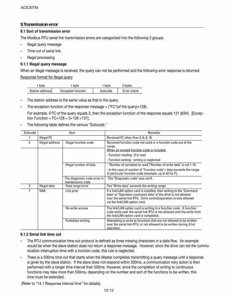
12-12
9.Transmission error9.1 Sort of transmission error
The Modbus RTU serial link transmission errors are categorized into the following 3 groups.
- Illegal query message
- Time out of serial link.
- Illegal processing
9.1.1 Illegal query message
When an illegal message is received, the query can not be performed and the following error response is returned.
Response format for illegal query
1 byte 1 byte 1 byte 2 bytes Station address Exception function Subcode Error check
- The station address is the same value as that in the query.
- The exception function of the response message = (“FC”(of the query)+128).
For example, if FC of the query equals 3, then the exception function of the response equals 131 (83H). [Excep-tion Function = FC+128 = 3+128 =131].
- The following table defines the various “Subcode."
Subcode1 Received FC other than 3, 6, 8, 16.2 Illegal address Illegal function code Received function code not used or a function code out of the
range.When an unused function code is included - Function reading: 0 is read- Function writing: writing is neglected
Illegal number of data - "Number of variables to read"/"Number of write data" is not 1-16. - In the case of number of "Function code"+ data exceeds the range of particular function code (example: up to 42 for F).
The diagnostic code error in maintenance code
-The "Diagnostic code" was not 0.
3 Illegal data Data range error The "Write data" exceeds the writing range.7 NAK Link prior If a link/LAN option card is installed, then writing to the "Command
data" or "Operation command data" of the drive is not allowed over the serial link RTU. Drive control/operation is only allowed via the link/LAN option card.
No write access The link/LAN option card is writing to a function code. A function code write over the serial link RTU is not allowed until the write from the link/LAN option card is completed.
Forbidden writing Attempting to write to functions that are not allowed to be written over the serial link RTU, or not allowed to be written during drive operation.
Illegal FC Item Remarks
9.1.2 Serial link time out
- The RTU communication time out protocol is defined as three missing characters in a data flow. An examplewould be when the slave station does not return a response message. However, since the drive can set the commu-nication interruption time with a function code, this rule is neglected.
- There is a 500ms time out that starts when the Master completes transmitting a query message until a responseis given by the slave station. If the slave does not respond within 500ms, a communication retry action is thenperformed with a longer time interval than 500ms. However, since the completion of writing to continuousfunctions may take more than 500ms, depending on the number and sort of the functions to be written, thistime must be extended.
(Refer to “14.1 Response interval time” for details).
ACE20TM
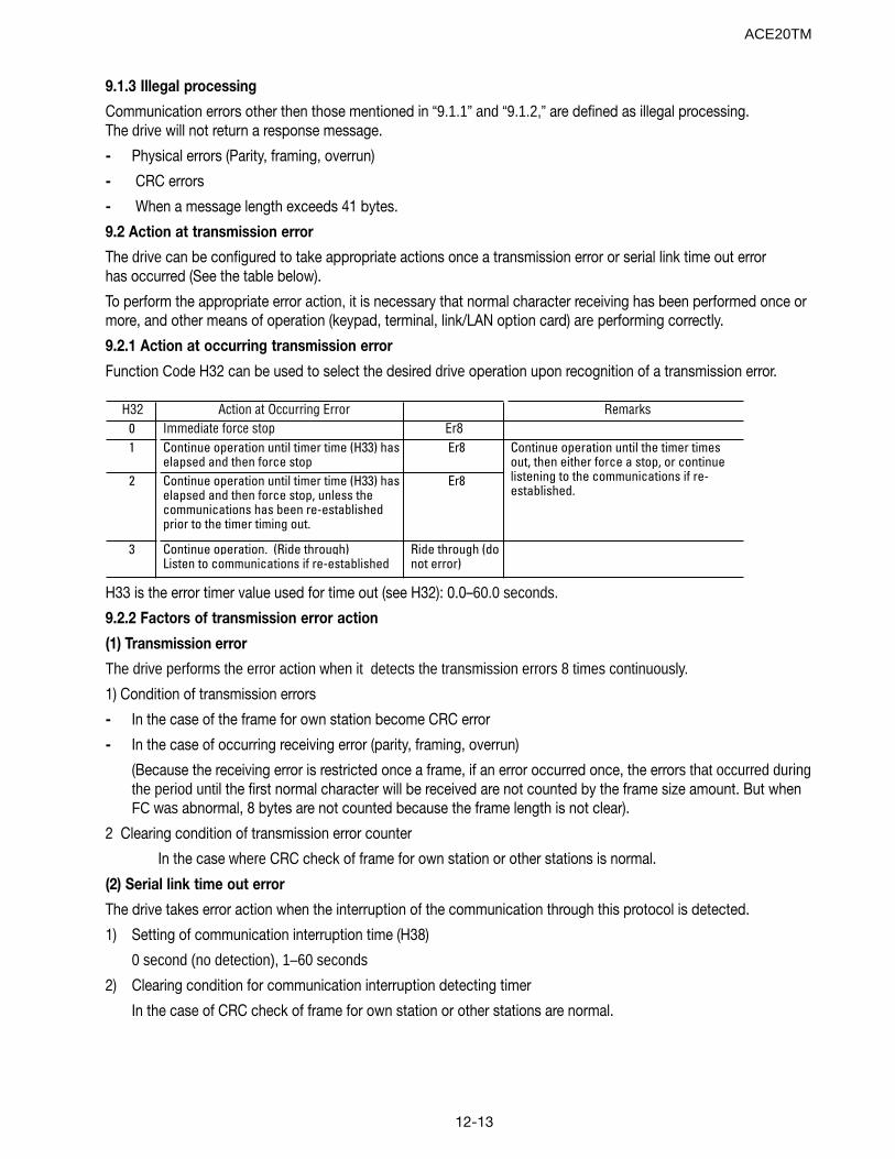
12-13
9.1.3 Illegal processing
Communication errors other then those mentioned in “9.1.1” and “9.1.2,” are defined as illegal processing.The drive will not return a response message.
- Physical errors (Parity, framing, overrun)
- CRC errors
- When a message length exceeds 41 bytes.
9.2 Action at transmission error
The drive can be configured to take appropriate actions once a transmission error or serial link time out errorhas occurred (See the table below).
To perform the appropriate error action, it is necessary that normal character receiving has been performed once ormore, and other means of operation (keypad, terminal, link/LAN option card) are performing correctly.
9.2.1 Action at occurring transmission error
Function Code H32 can be used to select the desired drive operation upon recognition of a transmission error.
H32 Action at Occurring Error Remarks0 Immediate force stop Er81 Continue operation until timer time (H33) has
elapsed and then force stopEr8
2 Continue operation until timer time (H33) has elapsed and then force stop, unless the communications has been re-established prior to the timer timing out.
Er8
3 Continue operation. (Ride through)Listen to communications if re-established
Ride through (do not error)
Continue operation until the timer times out, then either force a stop, or continue listening to the communications if re-established.
H33 is the error timer value used for time out (see H32): 0.0–60.0 seconds.
9.2.2 Factors of transmission error action
(1) Transmission error
The drive performs the error action when it detects the transmission errors 8 times continuously.
1) Condition of transmission errors
- In the case of the frame for own station become CRC error
- In the case of occurring receiving error (parity, framing, overrun)
(Because the receiving error is restricted once a frame, if an error occurred once, the errors that occurred duringthe period until the first normal character will be received are not counted by the frame size amount. But whenFC was abnormal, 8 bytes are not counted because the frame length is not clear).
2 Clearing condition of transmission error counter
In the case where CRC check of frame for own station or other stations is normal.
(2) Serial link time out error
The drive takes error action when the interruption of the communication through this protocol is detected.
1) Setting of communication interruption time (H38)
0 second (no detection), 1–60 seconds
2) Clearing condition for communication interruption detecting timer
In the case of CRC check of frame for own station or other stations are normal.
ACE20TM
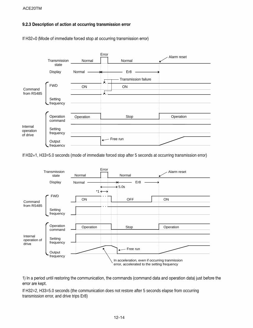
12-14
9.2.3 Description of action at occurring transmission error
If H32=0 (Mode of immediate forced stop at occurring transmission error)
Transmissionstate
Display
Internaloperationof drive
Commandfrom RS485
Operationcommand
FWD
Outputfrequency
Settingfrequency
Settingfrequency
Normal
Error
Normal
Normal Er8
Alarm reset
Free run
StopOperation
ON
Operation
ON
Transmission failure
If H32=1, H33=5.0 seconds (mode of immediate forced stop after 5 seconds at occurring transmission error)
Transmissionstate
Display
Internaloperation ofdrive
Commandfrom RS485
Operationcommand
FWD
Outputfrequency
Settingfrequency
Settingfrequency
Normal
Error
Normal
Normal Er8
Alarm reset
In acceleration, even if occurring tranmissionerror, accelerated to the setting frequency
Free run
StopOperation
ON
Operation
ON
5.0s*1
OFF
1) In a period until restoring the communication, the commands (command data and operation data) just before theerror are kept.
If H32=2, H33=5.0 seconds (the communication does not restore after 5 seconds elapse from occurringtransmission error, and drive trips Er8)
ACE20TM
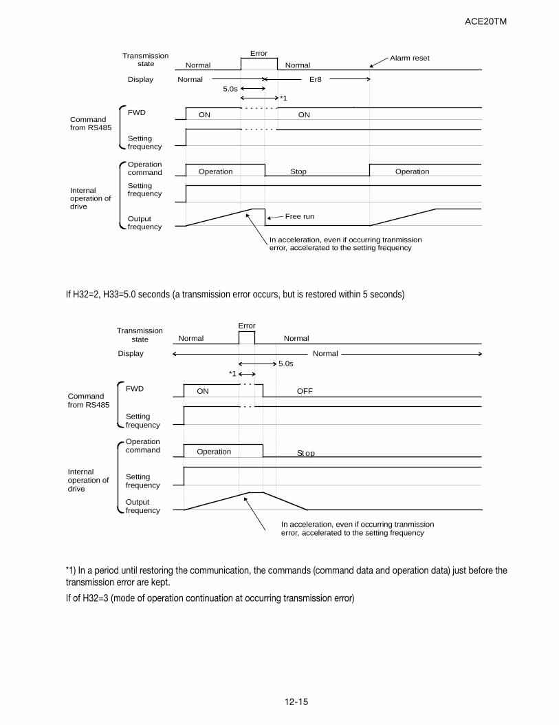
12-15
Transmissionstate
Display
Internaloperation ofdrive
Commandfrom RS485
Operationcommand
FWD
Outputfrequency
Settingfrequency
Settingfrequency
Normal
Error
Normal
Normal Er8
Alarm reset
In acceleration, even if occurring tranmissionerror, accelerated to the setting frequency
Free run
StopOperation
ON
Operation
*15.0s
ON
If H32=2, H33=5.0 seconds (a transmission error occurs, but is restored within 5 seconds)
Transmissionstate
Display
Internaloperation ofdrive
Commandfrom RS485
Operationcommand
FWD
Outputfrequency
Settingfrequency
Settingfrequency
Normal
Error
Normal
Normal
In acceleration, even if occurring tranmissionerror, accelerated to the setting frequency
St opOperation
ON
*15.0s
OFF
*1) In a period until restoring the communication, the commands (command data and operation data) just before thetransmission error are kept.
If of H32=3 (mode of operation continuation at occurring transmission error)
ACE20TM
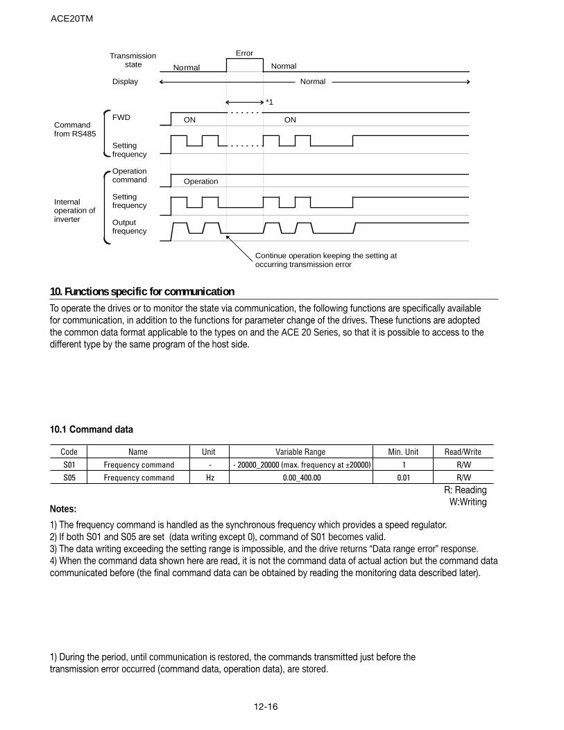
12-16
Transmissionstate
Display
Internaloperation ofinverter
Commandfrom RS485
Operationcommand
FWD
Outputfrequency
Settingfrequency
Settingfrequency
Normal
Error
Normal
Normal
Continue operation keeping the setting atoccurring transmission error
Operation
ON
*1
ON
10. Functions specific for communicationTo operate the drives or to monitor the state via communication, the following functions are specifically availablefor communication, in addition to the functions for parameter change of the drives. These functions are adoptedthe common data format applicable to the types on and the ACE 20 Series, so that it is possible to access to thedifferent type by the same program of the host side.
10.1 Command data
Code Name Unit Variable Range Min. Unit Read/WriteS01 Frequency command - - 20000_20000 (max. frequency at ±20000) 1 R/WS05 Frequency command Hz 0.00_400.00 0.01 R/W
Notes:
1) The frequency command is handled as the synchronous frequency which provides a speed regulator.2) If both S01 and S05 are set (data writing except 0), command of S01 becomes valid.3) The data writing exceeding the setting range is impossible, and the drive returns “Data range error” response.4) When the command data shown here are read, it is not the command data of actual action but the command datacommunicated before (the final command data can be obtained by reading the monitoring data described later).
R: ReadingW:Writing
1) During the period, until communication is restored, the commands transmitted just before thetransmission error occurred (command data, operation data), are stored.
ACE20TM
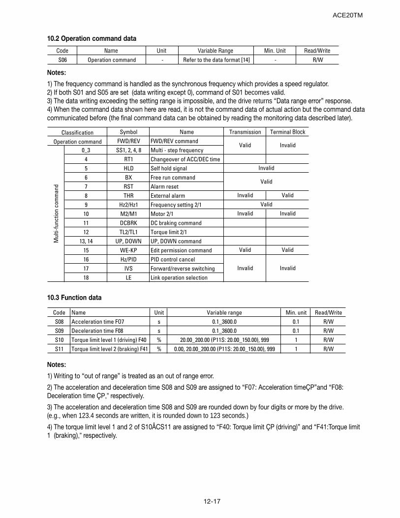
12-17
10.2 Operation command data
Code Name Unit Variable Range Min. Unit Read/WriteS06 Operation command - Refer to the data format [14] - R/W
Notes:
1) The frequency command is handled as the synchronous frequency which provides a speed regulator.2) If both S01 and S05 are set (data writing except 0), command of S01 becomes valid.3) The data writing exceeding the setting range is impossible, and the drive returns “Data range error” response.4) When the command data shown here are read, it is not the command data of actual action but the command datacommunicated before (the final command data can be obtained by reading the monitoring data described later).
Symbol Name Transmission Terminal BlockFWD/REV FWD/REV command
0_3 SS1, 2, 4, 8 Multi - step frequency4 RT1 Changeover of ACC/DEC time5 HLD Self hold signal6 BX Free run command7 RST Alarm reset8 THR External alarm Invalid Valid
9 Hz2/Hz1 Frequency setting 2/110 M2/M1 Motor 2/1 Invalid Invalid
11 DCBRK DC braking command12 TL2/TL1 Torque limit 2/1
13, 14 UP, DOWN UP, DOWN command15 WE-KP Edit permission command Valid Valid
16 Hz/PID PID control cancel17 IVS Forward/reverse switching18 LE Link operation selection
Mul
ti-fu
nctio
n co
mm
and
InvalidInvalid
Operation commandClassification
Invalid
Valid
Valid Invalid
Valid
10.3 Function data
Code Name Unit Variable range Min. unit Read/WriteS08 Acceleration time FO7 s 0.1_3600.0 0.1 R/WS09 Deceleration time F08 s 0.1_3600.0 0.1 R/WS10 Torque limit level 1 (driving) F40 % 20.00_200.00 (P11S: 20.00_150.00), 999 1 R/WS11 Torque limit level 2 (braking) F41 % 0.00, 20.00_200.00 (P11S: 20.00_150.00), 999 1 R/W
Notes:
1) Writing to “out of range” is treated as an out of range error.
2) The acceleration and deceleration time S08 and S09 are assigned to “F07: Acceleration timeÇP”and “F08:Deceleration time ÇP,” respectively.
3) The acceleration and deceleration time S08 and S09 are rounded down by four digits or more by the drive.(e.g., when 123.4 seconds are written, it is rounded down to 123 seconds.)
4) The torque limit level 1 and 2 of S10ÅCS11 are assigned to “F40: Torque limit ÇP (driving)” and “F41:Torque limit1 (braking),” respectively.
ACE20TM
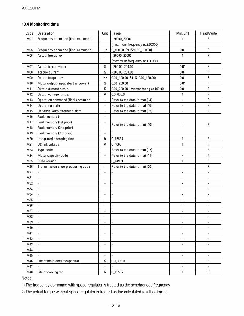
12-18
10.4 Monitoring data
Code Description Unit Range Min. unit Read/WriteM01 Frequency command (final command) - - 20000_20000 1 R
(maximum frequency at ±20000)M05 Frequency command (final command) Hz 0_400.00 (P11S: 0.00_120.00) 0.01 RM06 Actual frequency - - 20000_20000 1 R
(maximum frequency at ±20000)M07 Actual torque value % - 200.00_200.00 0.01 RM08 Torque current % - 200.00_200.00 0.01 RM09 Output frequency Hz 0.00_400.00 (P11S: 0.00_120.00) 0.01 RM10 Motor output (input electric power) % 0.00_200.00 0.01 RM11 Output current r. m. s. % 0.00_200.00 (inverter rating at 100.00) 0.01 RM12 Output voltage r. m. s. V 0.0_600.0 1 RM13 Operation command (final command) - Refer to the data format [14] - RM14 Operating state - Refer to the data format [16] - RM15 Universal output terminal data - Refer to the data format [15] - RM16 Fault memory 0 -M17 Fault memory (1st prior) -M18 Fault memory (2nd prior) -M19 Fault memory (3rd prior) -M20 Integrated operating time h 0_65535 1 RM21 DC link voltage V 0_1000 1 RM23 Type code - Refer to the data format [17] - RM24 Motor capacity code - Refer to the data format [11] - RM25 ROM version - 0_64999 1 RM26 Transmission error processing code - Refer to the data format [20] - RM27 - - - - -M31 - - - - -M32 - - - - -M33 - - - - -M34 - - - - -M35 - - - - -M36 - - - - -M37 - - - - -M38 - - - - -M39 - - - - -M40 - - - - -M41 - - - - -M42 - - - - -M43 - - - - -M44 - - - - -M45 - - - - -M46 Life of main circuit capacitor. % 0.0_100.0 0.1 RM47 - - - - -M48 Life of cooling fan. h 0_65535 1 R
Refer to the data format [10] - R
Notes:
1) The frequency command with speed regulator is treated as the synchronous frequency.
2) The actual torque without speed regulator is treated as the calculated result of torque.
ACE20TM
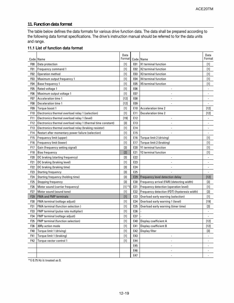
12-19
11. Function data format
The table below defines the data formats for various drive function data. The data shall be prepared according tothe following data format specifications. The drive’s instruction manual should be referred to for the data unitsand range.
11.1 List of function data format
Code NameData
Format Code NameData
Format
F00 Data protection [1] E01 X1 terminal function [1]F01 Frequency command 1 [1] E02 X2 terminal function [1]F02 Operation method [1] E03 X3 terminal function [1]F03 Maximum output frequency 1 [1] E04 X4 terminal function [1]F04 Base frequency 1 [1] E05 X5 terminal function [1]F05 Rated voltage 1 [1] E06 - -F06 Maximum output voltage 1 [1] E07 - -F07 Acceleration time 1 [12] E08 - -F08 Deceleration time 1 [12] E09 - -F09 Torque boost 1 [1] E10 Acceleration time 2 [12]F10 Electronics thermal overload relay 1 (selection) [1] E11 Deceleration time 2 [12]F11 Electronics thermal overload relay 1 (level) [19] E12 - -F12 Electronics thermal overload relay 1 (thermal time constant) [3] E13 - -F13 Electronics thermal overload relay (braking resistor) [1] E14 - -F14 Restart after momentary power failure (selection) [1] E15 - -F15 Frequency limit (upper) [1] E16 Torque limit 2 (driving) [1]F16 Frequency limit (lower) [1] E17 Torque limit 2 (braking) [1]F17 Gain (frequency setting signal) [3] E20 Y1 terminal function [1]F18 Bias frequency [2] E21 Y2 terminal function [1]F20 DC braking (starting frequency) [3] E22 - -F21 DC braking (braking level) [1] E23 - -F22 DC braking (braking time) [3] E24 - -F23 Starting frequency [3] E25 - -F24 Starting frequency (holding time) [3] E29 Frequency level detection delay [12]F25 Stopping frequency [3] E30 Frequency arrival (FAR) (detecting width) [3]F26 Motor sound (carrier frequency) [1] *1 E31 Frequency detection (operation level) [1]F27 Motor sound (sound tone) [1] E32 Frequency detection (FDT) (hysteresis width) [3]F29 FMA and FMP terminals [1] E33 Overload early warning (selection) [1]F30 FMA terminal (voltage adjust) [1] E34 Overload early warning 1 (level) [19]F31 FMA terminal (function selection ) [1] E35 Overload early warning (timer time) [3]F33 FMP terminal (pulse rate multiplier) [1] E36 - -F34 FMP terminal (voltage adjust) [1] E37 - -F35 FMP terminal (function selection) [1] E40 Display coefficient A [12]F36 30Ry action mode [1] E41 Display coefficient B [12]F40 Torque limit 1 (driving) [1] E42 Display filter [3]F41 Torque limit 1 (braking) [1] E43 - -F42 Torque vector control 1 [1] E44 - -
E45 - -E46 - -E47 - -
*1) 0.75 Hz is treated as 0.
ACE20TM
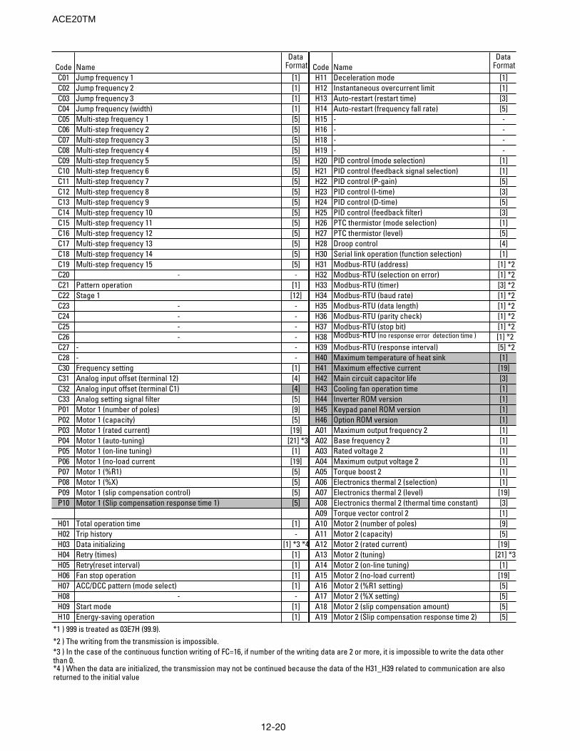
12-20
Code NameData
Format Code NameData
FormatC01 Jump frequency 1 [1] H11 Deceleration mode [1]C02 Jump frequency 2 [1] H12 Instantaneous overcurrent limit [1]C03 Jump frequency 3 [1] H13 Auto-restart (restart time) [3]C04 Jump frequency (width) [1] H14 Auto-restart (frequency fall rate) [5]C05 Multi-step frequency 1 [5] H15 - -C06 Multi-step frequency 2 [5] H16 - -C07 Multi-step frequency 3 [5] H18 - -C08 Multi-step frequency 4 [5] H19 - -C09 Multi-step frequency 5 [5] H20 PID control (mode selection) [1]C10 Multi-step frequency 6 [5] H21 PID control (feedback signal selection) [1]C11 Multi-step frequency 7 [5] H22 PID control (P-gain) [5]C12 Multi-step frequency 8 [5] H23 PID control (I-time) [3]C13 Multi-step frequency 9 [5] H24 PID control (D-time) [5]C14 Multi-step frequency 10 [5] H25 PID control (feedback filter) [3]C15 Multi-step frequency 11 [5] H26 PTC thermistor (mode selection) [1]C16 Multi-step frequency 12 [5] H27 PTC thermistor (level) [5]C17 Multi-step frequency 13 [5] H28 Droop control [4]C18 Multi-step frequency 14 [5] H30 Serial link operation (function selection) [1]C19 Multi-step frequency 15 [5] H31 Modbus-RTU (address) [1] *2C20 - - H32 Modbus-RTU (selection on error) [1] *2C21 Pattern operation [1] H33 Modbus-RTU (timer) [3] *2C22 Stage 1 [12] H34 Modbus-RTU (baud rate) [1] *2C23 - - H35 Modbus-RTU (data length) [1] *2C24 - - H36 Modbus-RTU (parity check) [1] *2C25 - - H37 Modbus-RTU (stop bit) [1] *2C26 - - H38 Modbus-RTU (no response error detection time ) [1] *2C27 - - H39 Modbus-RTU (response interval) [5] *2C28 - - H40 Maximum temperature of heat sink [1]C30 Frequency setting [1] H41 Maximum effective current [19]C31 Analog input offset (terminal 12) [4] H42 Main circuit capacitor life [3]C32 Analog input offset (terminal C1) [4] H43 Cooling fan operation time [1]C33 Analog setting signal filter [5] H44 Inverter ROM version [1]P01 Motor 1 (number of poles) [9] H45 Keypad panel ROM version [1]P02 Motor 1 (capacity) [5] H46 Option ROM version [1]P03 Motor 1 (rated current) [19] A01 Maximum output frequency 2 [1]P04 Motor 1 (auto-tuning) [21] *3 A02 Base frequency 2 [1]P05 Motor 1 (on-line tuning) [1] A03 Rated voltage 2 [1]P06 Motor 1 (no-load current [19] A04 Maximum output voltage 2 [1]P07 Motor 1 (%R1) [5] A05 Torque boost 2 [1]P08 Motor 1 (%X) [5] A06 Electronics thermal 2 (selection) [1]P09 Motor 1 (slip compensation control) [5] A07 Electronics thermal 2 (level) [19]P10 Motor 1 (Slip compensation response time 1) [5] A08 Electronics thermal 2 (thermal time constant) [3]
A09 Torque vector control 2 [1]H01 Total operation time [1] A10 Motor 2 (number of poles) [9]H02 Trip history - A11 Motor 2 (capacity) [5]H03 Data initializing [1] *3 *4 A12 Motor 2 (rated current) [19]H04 Retry (times) [1] A13 Motor 2 (tuning) [21] *3H05 Retry(reset interval) [1] A14 Motor 2 (on-line tuning) [1]H06 Fan stop operation [1] A15 Motor 2 (no-load current) [19]H07 ACC/DCC pattern (mode select) [1] A16 Motor 2 (%R1 setting) [5]H08 - - A17 Motor 2 (%X setting) [5]H09 Start mode [1] A18 Motor 2 (slip compensation amount) [5]H10 Energy-saving operation [1] A19 Motor 2 (Slip compensation response time 2) [5]
*1 ) 999 is treated as 03E7H (99.9).*2 ) The writing from the transmission is impossible.*3 ) In the case of the continuous function writing of FC=16, if number of the writing data are 2 or more, it is impossible to write the data other than 0.*4 ) When the data are initialized, the transmission may not be continued because the data of the H31_H39 related to communication are also returned to the initial value
ACE20TM
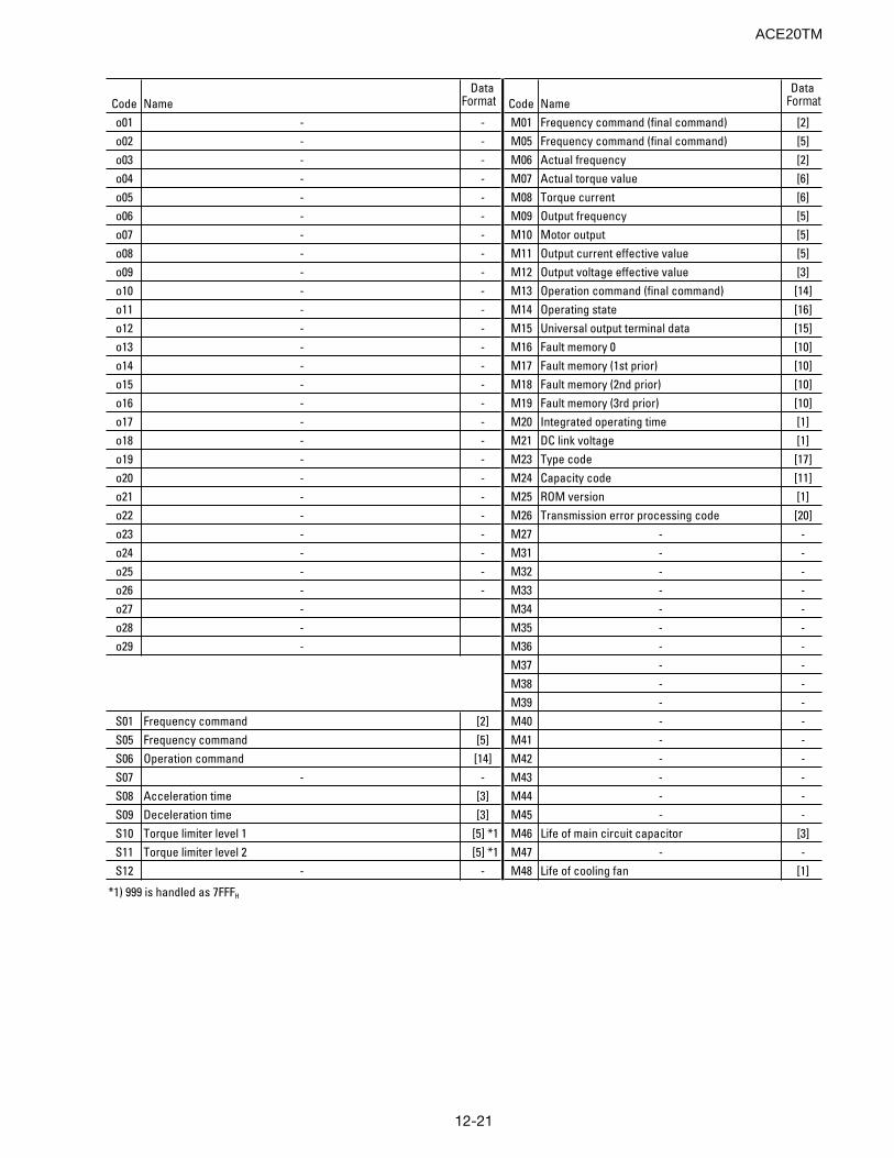
12-21
Code NameData
Format Code NameData
Format
o01 - - M01 Frequency command (final command) [2]o02 - - M05 Frequency command (final command) [5]o03 - - M06 Actual frequency [2]o04 - - M07 Actual torque value [6]o05 - - M08 Torque current [6]o06 - - M09 Output frequency [5]o07 - - M10 Motor output [5]o08 - - M11 Output current effective value [5]o09 - - M12 Output voltage effective value [3]o10 - - M13 Operation command (final command) [14]o11 - - M14 Operating state [16]o12 - - M15 Universal output terminal data [15]o13 - - M16 Fault memory 0 [10]o14 - - M17 Fault memory (1st prior) [10]o15 - - M18 Fault memory (2nd prior) [10]o16 - - M19 Fault memory (3rd prior) [10]o17 - - M20 Integrated operating time [1]o18 - - M21 DC link voltage [1]o19 - - M23 Type code [17]o20 - - M24 Capacity code [11]o21 - - M25 ROM version [1]o22 - - M26 Transmission error processing code [20]o23 - - M27 - -o24 - - M31 - -o25 - - M32 - -o26 - - M33 - -o27 - M34 - -o28 - M35 - -o29 - M36 - -
M37 - -M38 - -M39 - -
S01 Frequency command [2] M40 - -S05 Frequency command [5] M41 - -S06 Operation command [14] M42 - -S07 - - M43 - -S08 Acceleration time [3] M44 - -S09 Deceleration time [3] M45 - -S10 Torque limiter level 1 [5] *1 M46 Life of main circuit capacitor [3]S11 Torque limiter level 2 [5] *1 M47 - -S12 - - M48 Life of cooling fan [1]
*1) 999 is handled as 7FFFH
ACE20TM
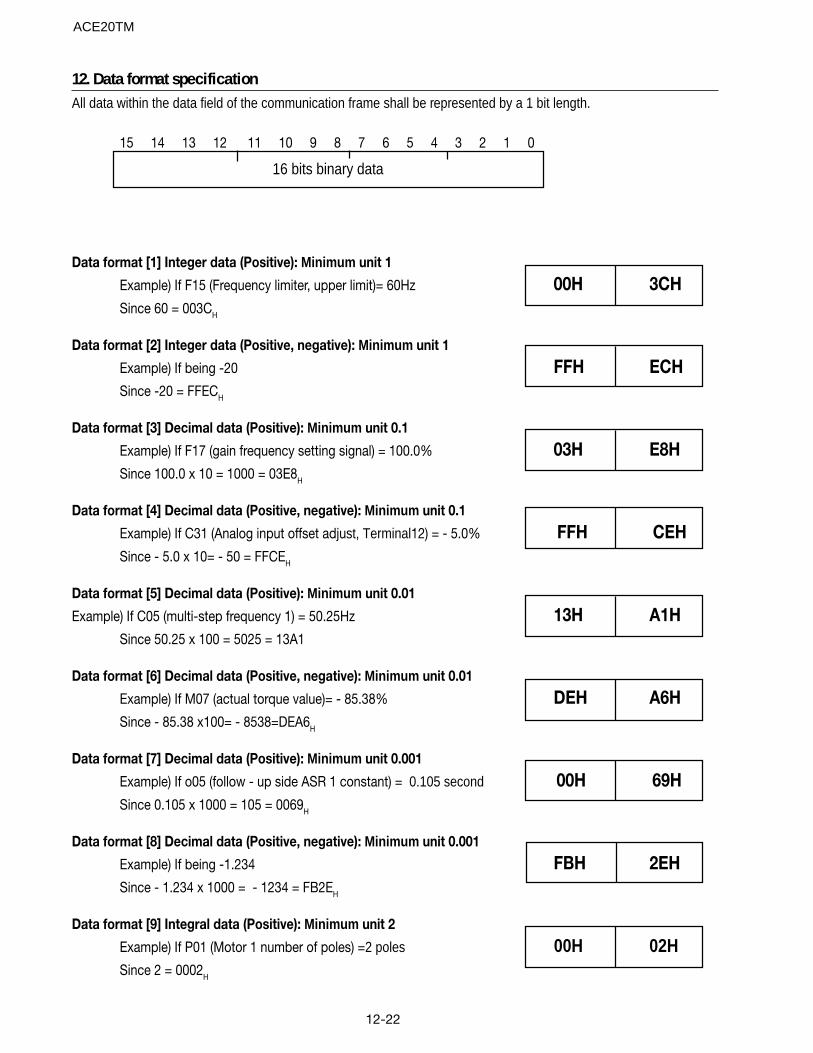
12-22
16 bits binary data
12. Data format specificationAll data within the data field of the communication frame shall be represented by a 1 bit length.
15 14 13 12 11 10 9 8 7 6 5 4 3 2 1 0
Data format [1] Integer data (Positive): Minimum unit 1
Example) If F15 (Frequency limiter, upper limit)= 60Hz 00H 3CHSince 60 = 003CH
Data format [2] Integer data (Positive, negative): Minimum unit 1
Example) If being -20 FFH ECHSince -20 = FFECH
Data format [3] Decimal data (Positive): Minimum unit 0.1
Example) If F17 (gain frequency setting signal) = 100.0% 03H E8HSince 100.0 x 10 = 1000 = 03E8H
Data format [4] Decimal data (Positive, negative): Minimum unit 0.1
Example) If C31 (Analog input offset adjust, Terminal12) = - 5.0% FFH CEHSince - 5.0 x 10= - 50 = FFCEH
Data format [5] Decimal data (Positive): Minimum unit 0.01
Example) If C05 (multi-step frequency 1) = 50.25Hz 13H A1HSince 50.25 x 100 = 5025 = 13A1
Data format [6] Decimal data (Positive, negative): Minimum unit 0.01
Example) If M07 (actual torque value)= - 85.38% DEH A6HSince - 85.38 x100= - 8538=DEA6H
Data format [7] Decimal data (Positive): Minimum unit 0.001
Example) If o05 (follow - up side ASR 1 constant) = 0.105 second 00H 69HSince 0.105 x 1000 = 105 = 0069H
Data format [8] Decimal data (Positive, negative): Minimum unit 0.001
Example) If being -1.234 FBH 2EHSince - 1.234 x 1000 = - 1234 = FB2EH
Data format [9] Integral data (Positive): Minimum unit 2
Example) If P01 (Motor 1 number of poles) =2 poles 00H 02HSince 2 = 0002H
ACE20TM
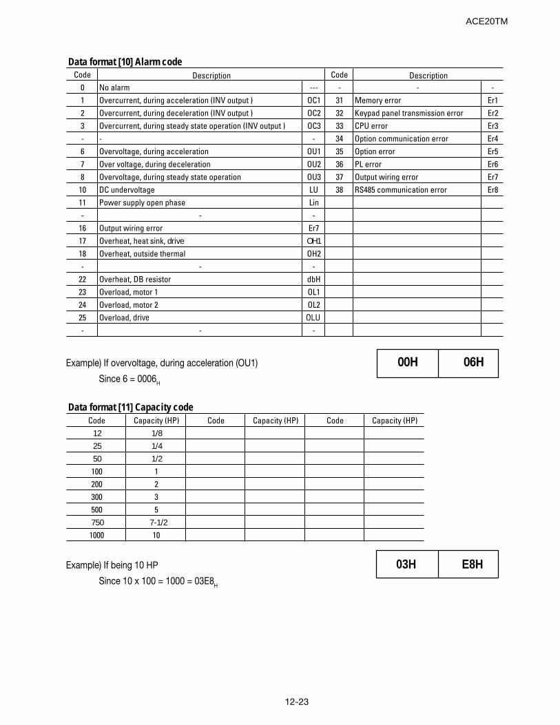
12-23
Code Code0 No alarm --- - - -1 Overcurrent, during acceleration (INV output ) OC1 31 Memory error Er12 Overcurrent, during deceleration (INV output ) OC2 32 Keypad panel transmission error Er23 Overcurrent, during steady state operation (INV output ) OC3 33 CPU error Er3- - - 34 Option communication error Er46 Overvoltage, during acceleration OU1 35 Option error Er57 Over voltage, during deceleration OU2 36 PL error Er68 Overvoltage, during steady state operation OU3 37 Output wiring error Er7
10 DC undervoltage LU 38 RS485 communication error Er811 Power supply open phase Lin- - -
16 Output wiring error Er717 Overheat, heat sink, drive OH118 Overheat, outside thermal OH2- - -
22 Overheat, DB resistor dbH23 Overload, motor 1 OL124 Overload, motor 2 OL225 Overload, drive OLU- - -
DescriptionDescription
Data format [10] Alarm code
Example) If overvoltage, during acceleration (OU1) 00H 06HSince 6 = 0006H
Data format [11] Capacity codeCode Capacity (HP) Code Capacity (HP) Code Capacity (HP)
12 1/825 1/450 1/2100 1200 2300 3500 5750 7-1/2
1000 10
Example) If being 10 HP 03H E8HSince 10 x 100 = 1000 = 03E8H
ACE20TM
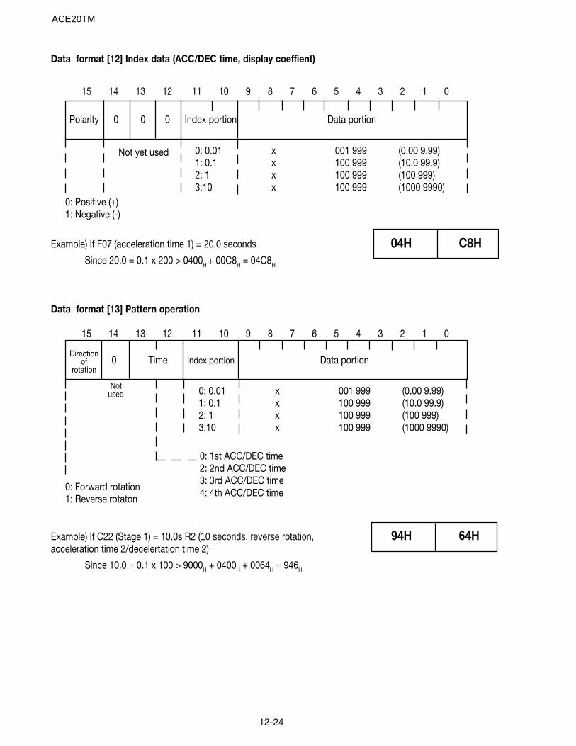
12-24
Data format [12] Index data (ACC/DEC time, display coeffient)
15 14 13 12 11 10 9 8 7 6 5 4 3 2 1 0
Polarity 0 0 0 Index portion Data portion
0: Positive (+)1: Negative (-)
Not yet used 0: 0.01 x 001 999 (0.00 9.99)1: 0.1 x 100 999 (10.0 99.9)2: 1 x 100 999 (100 999)3:10 x 100 999 (1000 9990)
Example) If F07 (acceleration time 1) = 20.0 seconds 04H C8HSince 20.0 = 0.1 x 200 > 0400H + 00C8H = 04C8H
15 14 13 12 11 10 9 8 7 6 5 4 3 2 1 0
Data format [13] Pattern operation
Directionof
rotation0 Time Index portion Data portion
0: Forward rotation1: Reverse rotaton
Notused
0: 1st ACC/DEC time2: 2nd ACC/DEC time3: 3rd ACC/DEC time4: 4th ACC/DEC time
0: 0.01 x 001 999 (0.00 9.99)1: 0.1 x 100 999 (10.0 99.9)2: 1 x 100 999 (100 999)3:10 x 100 999 (1000 9990)
Example) If C22 (Stage 1) = 10.0s R2 (10 seconds, reverse rotation, 94H 64Hacceleration time 2/decelertation time 2)
Since 10.0 = 0.1 x 100 > 9000H + 0400H + 0064H = 946H
ACE20TM
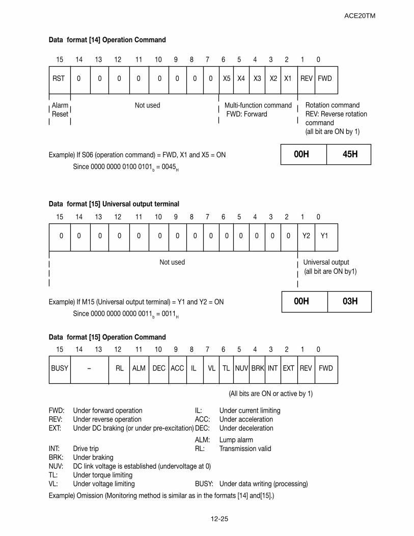
12-25
15 14 13 12 11 10 9 8 7 6 5 4 3 2 1 0
RST 0 0 0 0 0 0 0 0 X5 X4 X3 X2 X1 REV FWD
Alarm Not used Multi-function command Reset FWD: Forward
Rotation commandREV: Reverse rotationcommand(all bit are ON by 1)
Example) If S06 (operation command) = FWD, X1 and X5 = ON 00H 45HSince 0000 0000 0100 0101b = 0045H
Data format [14] Operation Command
Data format [15] Universal output terminal
15 14 13 12 11 10 9 8 7 6 5 4 3 2 1 0
0 0 0 0 0 0 0 0 0 0 0 0 0 0 Y2 Y1
Not used Universal output(all bit are ON by1)
Example) If M15 (Universal output terminal) = Y1 and Y2 = ON 00H 03HSince 0000 0000 0000 0011b = 0011H
Data format [15] Operation Command
15 14 13 12 11 10 9 8 7 6 5 4 3 2 1 0
BUSY – RL ALM DEC ACC IL VL TL NUV BRK INT EXT REV FWD
FWD: Under forward operation IL: Under current limitingREV: Under reverse operation ACC: Under accelerationEXT: Under DC braking (or under pre-excitation) DEC: Under deceleration
ALM: Lump alarmINT: Drive trip RL: Transmission validBRK: Under brakingNUV: DC link voltage is established (undervoltage at 0)TL: Under torque limitingVL: Under voltage limiting BUSY: Under data writing (processing)
Example) Omission (Monitoring method is similar as in the formats [14] and[15].)
(All bits are ON or active by 1)
ACE20TM
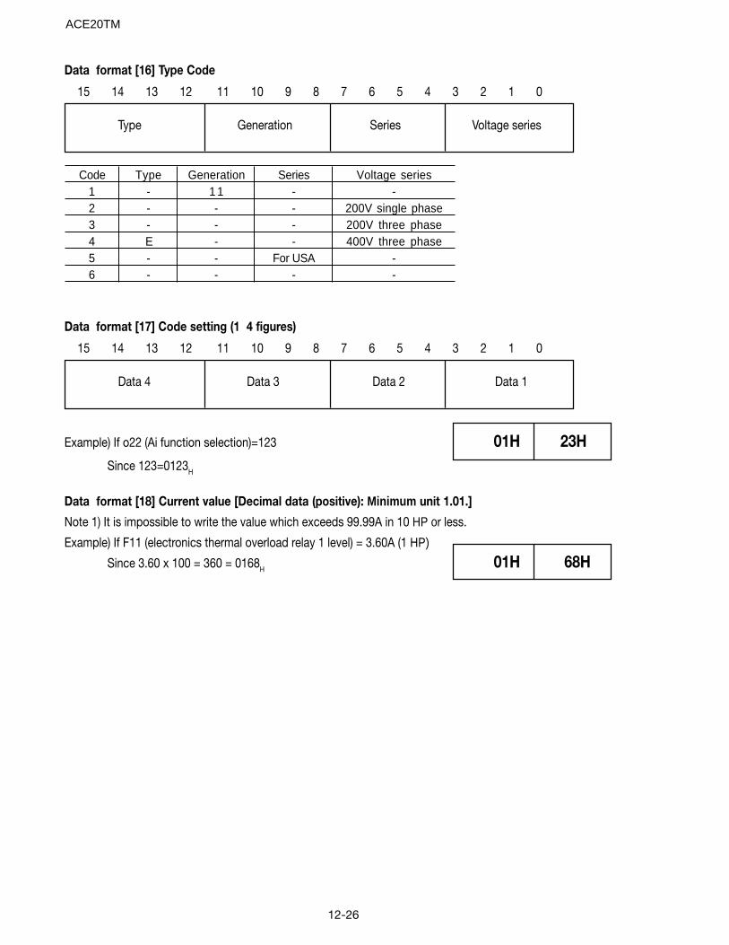
12-26
Data format [16] Type Code
15 14 13 12 11 10 9 8 7 6 5 4 3 2 1 0
Type Generation Series Voltage series
Code Type Generation Series Voltage series1 - 1 1 - -2 - - - 200V single phase3 - - - 200V three phase4 E - - 400V three phase5 - - For USA -6 - - - -
Data format [17] Code setting (1 4 figures)
15 14 13 12 11 10 9 8 7 6 5 4 3 2 1 0
Data 4 Data 3 Data 2 Data 1
Example) If o22 (Ai function selection)=123 01H 23HSince 123=0123H
Data format [18] Current value [Decimal data (positive): Minimum unit 1.01.]
Note 1) It is impossible to write the value which exceeds 99.99A in 10 HP or less.
Example) If F11 (electronics thermal overload relay 1 level) = 3.60A (1 HP)
Since 3.60 x 100 = 360 = 0168H 01H 68H
ACE20TM
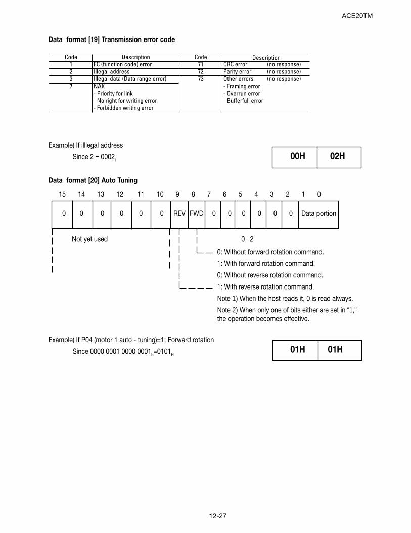
12-27
Data format [19] Transmission error code
Code Description Code1 FC (function code) error 71 CRC error (no response)2 Illegal address 72 Parity error (no response)3 Illegal data (Data range error) 73 Other errors (no response)7 NAK - Framing error
- Priority for link - Overrun error- No right for writing error - Bufferfull error- Forbidden writing error
Description
Example) If illlegal address
Since 2 = 0002H 00H 02H
Data format [20] Auto Tuning
15 14 13 12 11 10 9 8 7 6 5 4 3 2 1 0
0 0 0 0 0 0 REV FWD 0 0 0 0 0 0 Data portion
Not yet used 0 2
0: Without forward rotation command.
1: With forward rotation command.
0: Without reverse rotation command.
1: With reverse rotation command.
Note 1) When the host reads it, 0 is read always.
Note 2) When only one of bits either are set in “1,"the operation becomes effective.
Example) If P04 (motor 1 auto - tuning)=1: Forward rotation
Since 0000 0001 0000 0001b=0101H01H 01H
ACE20TM
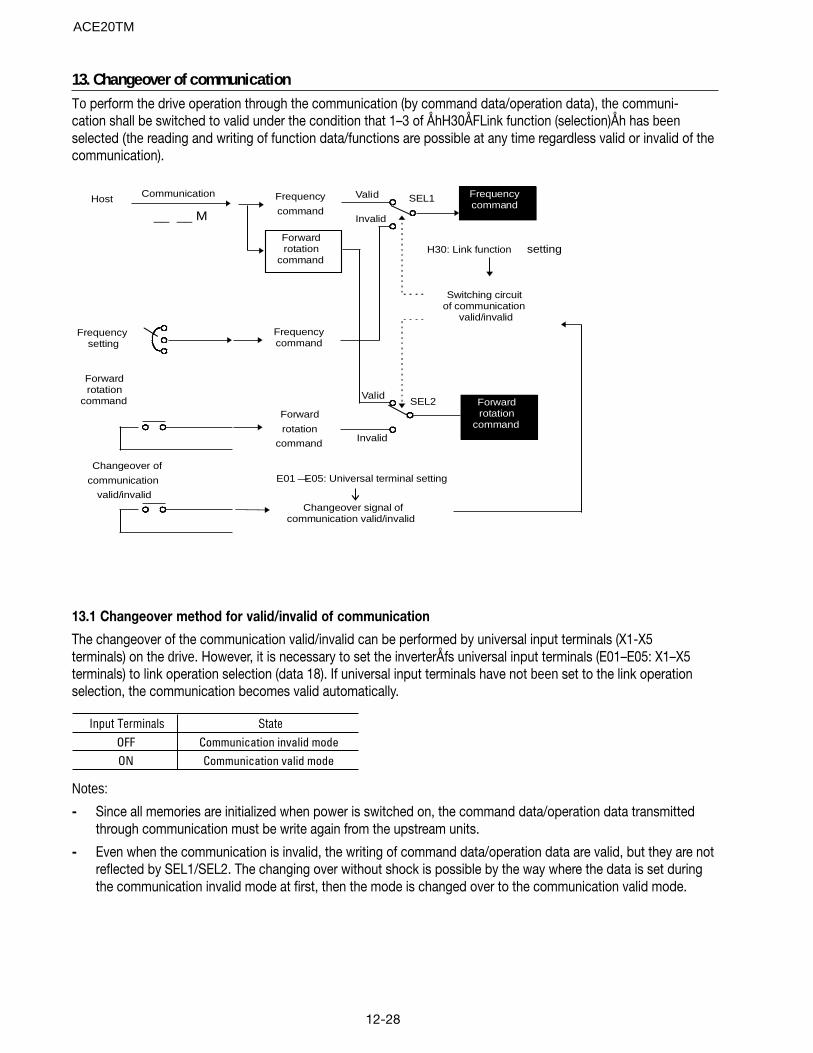
12-28
13. Changeover of communicationTo perform the drive operation through the communication (by command data/operation data), the communi-cation shall be switched to valid under the condition that 1–3 of ÅhH30ÅFLink function (selection)Åh has beenselected (the reading and writing of function data/functions are possible at any time regardless valid or invalid of thecommunication).
Frequencysetting
Changeover signal ofcommunication valid/invalid
E01 —E05: Universal terminal setting
Frequencycommand
Forwardrotation
command
Frequencycommand
Frequency
command
Forward
rotation
command
Host
Changeover of
communication
valid/invalid
Invalid
Valid
Forwardrotation
command
Switching circuit of communication
valid/invalid
H30: Link function setting
Invalid
Communication
__ __ M
Valid
SEL2
SEL1
Forwardrotation
command
13.1 Changeover method for valid/invalid of communication
The changeover of the communication valid/invalid can be performed by universal input terminals (X1-X5terminals) on the drive. However, it is necessary to set the inverterÅfs universal input terminals (E01–E05: X1–X5terminals) to link operation selection (data 18). If universal input terminals have not been set to the link operationselection, the communication becomes valid automatically.
Input Terminals StateOFF Communication invalid modeON Communication valid mode
Notes:
- Since all memories are initialized when power is switched on, the command data/operation data transmittedthrough communication must be write again from the upstream units.
- Even when the communication is invalid, the writing of command data/operation data are valid, but they are notreflected by SEL1/SEL2. The changing over without shock is possible by the way where the data is set duringthe communication invalid mode at first, then the mode is changed over to the communication valid mode.
ACE20TM
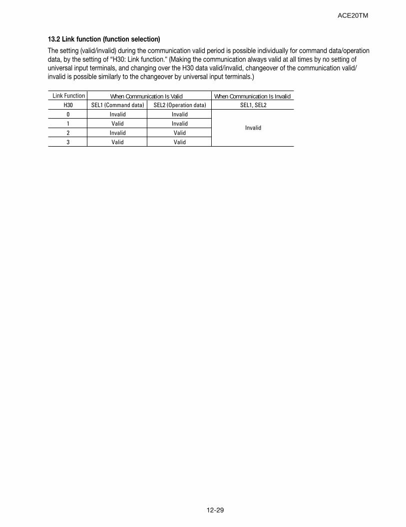
12-29
13.2 Link function (function selection)
The setting (valid/invalid) during the communication valid period is possible individually for command data/operationdata, by the setting of “H30: Link function." (Making the communication always valid at all times by no setting ofuniversal input terminals, and changing over the H30 data valid/invalid, changeover of the communication valid/invalid is possible similarly to the changeover by universal input terminals.)
Link FunctionH30 SEL1 (Command data) SEL2 (Operation data) SEL1, SEL2
0 Invalid Invalid1 Valid Invalid2 Invalid Valid3 Valid Valid
When Communication Is Valid When Communication Is Invalid
Invalid
ACE20TM
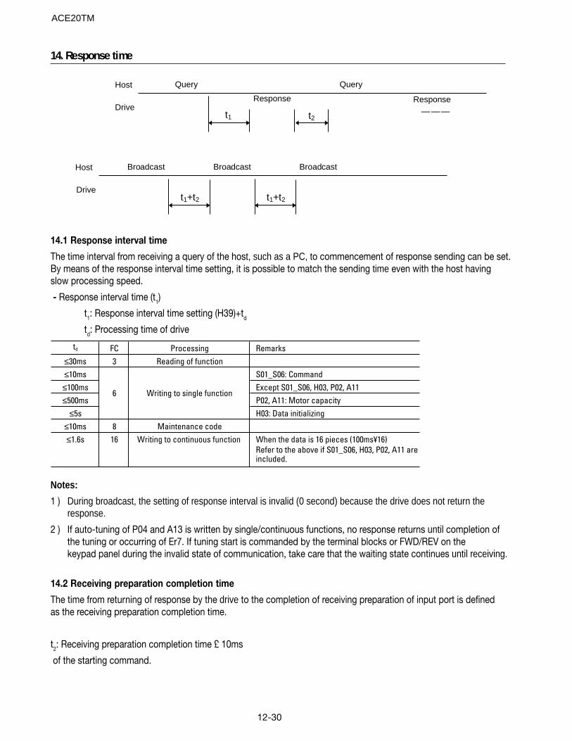
12-30
14. Response time
Drive
Host
t2t1
Response———
Query
Response
Query
Drive
Host
t1+t2t1+t2
BroadcastBroadcastBroadcast
14.1 Response interval time
The time interval from receiving a query of the host, such as a PC, to commencement of response sending can be set.By means of the response interval time setting, it is possible to match the sending time even with the host havingslow processing speed.
- Response interval time (t1)
t1: Response interval time setting (H39)+td
td: Processing time of drive
td FC Processing Remarks≤30ms 3 Reading of function≤10ms S01_S06: Command≤100ms Except S01_S06, H03, P02, A11≤500ms P02, A11: Motor capacity
≤5s H03: Data initializing≤10ms 8 Maintenance code≤1.6s 16 Writing to continuous function When the data is 16 pieces (100ms¥16)
Refer to the above if S01_S06, H03, P02, A11 are included.
6 Writing to single function
Notes:
1 ) During broadcast, the setting of response interval is invalid (0 second) because the drive does not return theresponse.
2 ) If auto-tuning of P04 and A13 is written by single/continuous functions, no response returns until completion ofthe tuning or occurring of Er7. If tuning start is commanded by the terminal blocks or FWD/REV on thekeypad panel during the invalid state of communication, take care that the waiting state continues until receiving.
14.2 Receiving preparation completion time
The time from returning of response by the drive to the completion of receiving preparation of input port is definedas the receiving preparation completion time.
t2: Receiving preparation completion time £ 10ms
of the starting command.
ACE20TM
13-1
13. Compliance with standards
13.1 UL/cUL standards13.1.1 GeneralThe UL standards stand for Underwriters Laboratories Inc. and they are safety standards aimed at preventing fire andother accidents in the United States, thereby providing protection for operators, service personnel and other persons.
The cUL standards are established by UL to be in compliance with the CSA standards. The effect on products certified forthe cUL standards is equal to that of products certified for the CSA standards.
13.1.2 PrecautionsWhen using UL/cUL certified products, refer to “Compliance with UL/cUL standards” on page vi and vii in the introduction.
13.2 Electromagnetic Compatibility (EMC) [Available only for products with CE mark]13.2.1 GeneralThe CE mark indicated on the ACE 20 Series refers to the European minister directorate directive 89/336/EEC con-cerning the environmental electromagnetic compatibility, EMC. Other directives are not included.
The CE mark on the drive does not attest that the entire machine or system housing complies with the EMC directive.Therefore, application of the CE mark to the entire machine or system will be done at the responsibility of the manufacturerof the machine. This is because:
1) The CE mark attached on the drive supposes operation of the product under “certain conditions." Satisfac-tion of the conditions is up to the manufacturer of the machine.
2) Generally speaking, various devices are used in a machine or system in addition to the drive. Therefore, consider-ation of the entire machine or system must be addressed by the manufacturer of the machine.
The EMC directive includes immunity to incoming noise and emission of outgoing noise. The general purpose drivehouses an internal element switching at high speed which generates electrical noise.
EMC product standard EN61800-3/1996Immunity : Second environment [ Industrial environment ]
Emission : First environment [Domestic environment for 230V Single phase, 460V Three phase ]
Emission : Second environment [ Industrial environment for 230V Three phase]
Above-mentioned “certain conditions” include installation of a dedicated RFI filter in a metallic control panel.
13.2.2 RFI filterPlease contact the drive distributor for the recommended RFI filter.
Remark : Refer to the RFI filter manual for details.
To minimize the conducted radio disturbance in the power distribution system, the length of the motor cables should be asshort as possible. It is the user’s responsibility to confirm that the apparatus, into which the drive is installed, conforms tothe EMC directive when longer motor cables are used and when other installation conditions are different from those describedin the recommended RFI filter manual.
13.2.3 Recommended Installation InstructionsThese instructions must be followed to conformed to the EMC Directive.
Follow the usual safety procedures when working with electrical equipment. All electrical connections to the filter, driveand motor must be made by a qualified electrical technician.
(Refer to Fig. 13-2-1)
1) Use the correct recommended filter.
2) The back panel of the cabinet should be prepared for the mounting dimensions of the filter. Care should be takento remove any paint, etc., from the mounting holes and face area of the panel. This will ensure the best possiblegrounding of the filter.
ACE20TM
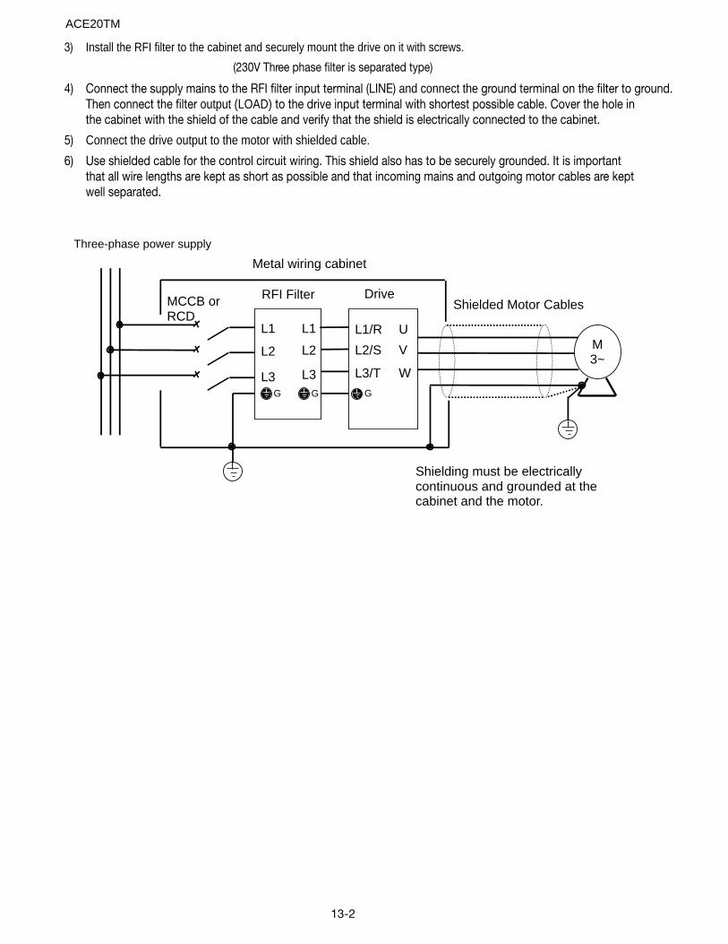
13-2
3) Install the RFI filter to the cabinet and securely mount the drive on it with screws.
(230V Three phase filter is separated type)
4) Connect the supply mains to the RFI filter input terminal (LINE) and connect the ground terminal on the filter to ground.Then connect the filter output (LOAD) to the drive input terminal with shortest possible cable. Cover the hole inthe cabinet with the shield of the cable and verify that the shield is electrically connected to the cabinet.
5) Connect the drive output to the motor with shielded cable.
6) Use shielded cable for the control circuit wiring. This shield also has to be securely grounded. It is importantthat all wire lengths are kept as short as possible and that incoming mains and outgoing motor cables are keptwell separated.
Three-phase power supply
Metal wiring cabinet
Shielded Motor Cables
Shielding must be electricallycontinuous and grounded at thecabinet and the motor.
M3~
W
V
U
L3
L2
L1
G
L3
L2
L1
G
L3/T
L2/S
L1/R
G
DriveRFI FilterMCCB orRCD
ACE20TM

13-3
13.3 Compliance with low voltage directive in EU [Available only for products with TÜV or CE mark]13.3.1 GeneralThe general purpose drive is applicable for the low voltage directive in EU. Compliance of the ACE 20 Series withEN 50178/1997 has been obtained from a testing organization in EU, and compliance with the low voltage directive isassured.
13.3.2 PrecautionsRefer to “Compliance with low voltage directive in EU” on pages iv and v in the introduction when using this product asone complying with the low voltage directive in EU.
ACE20TM

13-4
Notes:ACE20TM

ACE20TM

Boston Gear14 Hayward Street, Quincy, MA 02171617.328.3300 fax 617.479.6238www.bostongear.comAn Altra Industrial Motion Company
ACE20TM09/03