Embed Size (px)
Citation preview
40727-17031 14SORB-48
®
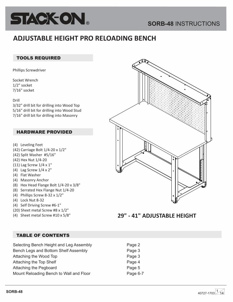
ADJUSTABLE HEIGHT PRO RELOADING BENCH
SORB-48 INSTRUCTIONS
TABLE OF CONTENTS
(4) Leveling Feet(42) Carriage Bolt 1/4-20 x 1/2"(42) Split Washer #5/16" (42) Hex Nut 1/4-20(11) Lag Screw 1/4 x 1" (4) Lag Screw 1/4 x 2" (4) Flat Washer (4) Masonry Anchor(8) Hex Head Flange Bolt 1/4-20 x 3/8" (8) Serrated Hex Flange Nut 1/4-20 (4) Phillips Screw 8-32 x 1/2" (4) Lock Nut 8-32 (4) Self Driving Screw #6-1" (20) Sheet metal Screw #8 x 1/2"(4) Sheet metal Screw #10 x 5/8"
TOOLS REQUIRED
Phillips Screwdriver
Socket Wrench1/2" socket 7/16" socket
Drill3/32" drill bit for drilling into Wood Top5/16" drill bit for drilling into Wood Stud 7/16" drill bit for drilling into Masonry
Selecting Bench Height and Leg Assembly Page 2Bench Legs and Bottom Shelf Assembly Page 3Attaching the Wood Top Page 3Attaching the Top Shelf Page 4 Attaching the Pegboard Page 5Mount Reloading Bench to Wall and Floor Page 6-7
29" - 41" ADJUSTABLE HEIGHT
HARDWARE PROVIDED
SORB-48
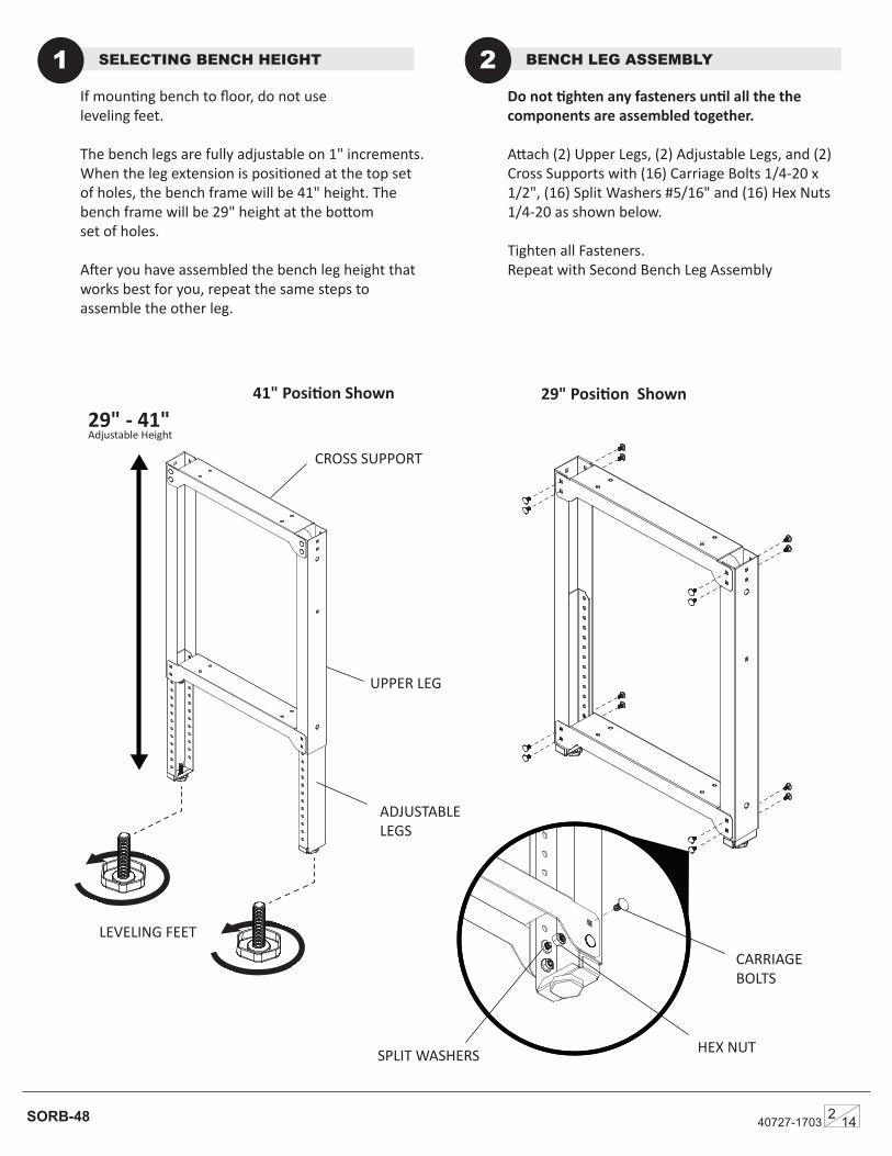
29" Position Shown
If mounting bench to floor, do not useleveling feet.
The bench legs are fully adjustable on 1" increments. When the leg extension is positioned at the top set of holes, the bench frame will be 41" height. The bench frame will be 29" height at the bottom set of holes.
After you have assembled the bench leg height that works best for you, repeat the same steps to assemble the other leg.
SELECTING BENCH HEIGHT1 Do not tighten any fasteners until all the the components are assembled together.
Attach (2) Upper Legs, (2) Adjustable Legs, and (2) Cross Supports with (16) Carriage Bolts 1/4-20 x 1/2", (16) Split Washers #5/16" and (16) Hex Nuts 1/4-20 as shown below.
Tighten all Fasteners.Repeat with Second Bench Leg Assembly
BENCH LEG ASSEMBLY2
41" Position Shown
40727-17032 14
LEVELING FEET
UPPER LEG
CROSS SUPPORT
ADJUSTABLE LEGS
CARRIAGE BOLTS
SPLIT WASHERS HEX NUT
29" - 41" Adjustable Height
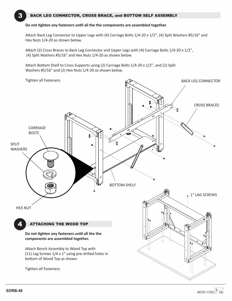
Do not tighten any fasteners until all the the components are assembled together.
Attach Back Leg Connector to Upper Legs with (4) Carriage Bolts 1/4-20 x 1/2", (4) Split Washers #5/16" and Hex Nuts 1/4-20 as shown below.
Attach (2) Cross Braces to Back Leg Connector and Upper Legs with (4) Carriage Bolts 1/4-20 x 1/2", (4) Split Washers #5/16" and Hex Nuts 1/4-20 as shown below.
Attach Bottom Shelf to Cross Supports using (2) Carriage Bolts 1/4-20 x 1/2", and (2) Split Washers #5/16" and (2) Hex Nuts 1/4-20 as shown below.
Tighten all Fasteners.
SORB-48
BACK LEG CONNECTOR, CROSS BRACE, and BOTTOM SELF ASSEMBLY3
Do not tighten any fasteners until all the the components are assembled together.
Attach Bench Assembly to Wood Top with(11) Lag Screws 1/4 x 1" using pre-drilled holes in bottom of Wood Top as shown.
Tighten all Fasteners.
ATTACHING THE WOOD TOP4
40727-17033 14
CARRIAGE BOLTS
CARRIAGE BOLTS
HEX NUT
SPLIT WASHERS
1" LAG SCREWS
CROSS BRACES
BACK LEG CONNECTOR
BOTTOM SHELF
SORB-48
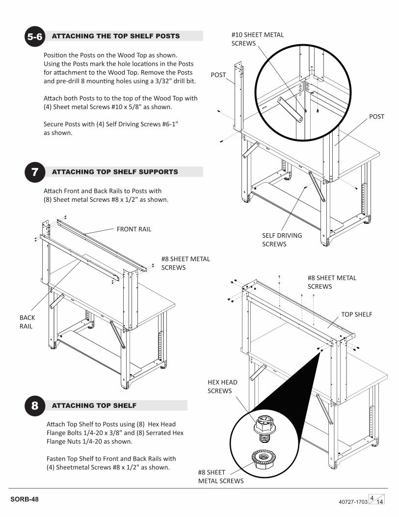
Position the Posts on the Wood Top as shown. Using the Posts mark the hole locations in the Posts for attachment to the Wood Top. Remove the Posts and pre-drill 8 mounting holes using a 3/32" drill bit.
Attach both Posts to to the top of the Wood Top with (4) Sheet metal Screws #10 x 5/8" as shown.
Secure Posts with (4) Self Driving Screws #6-1" as shown.
ATTACHING THE TOP SHELF POSTS5-6
ATTACHING TOP SHELF8
ATTACHING TOP SHELF SUPPORTS7Attach Front and Back Rails to Posts with (8) Sheet metal Screws #8 x 1/2" as shown.
Attach Top Shelf to Posts using (8) Hex Head Flange Bolts 1/4-20 x 3/8" and (8) Serrated Hex Flange Nuts 1/4-20 as shown.
Fasten Top Shelf to Front and Back Rails with (4) Sheetmetal Screws #8 x 1/2" as shown.
40727-17034 14
#10 SHEET METAL SCREWS
SELF DRIVINGSCREWS
#8 SHEET METAL SCREWS
#8 SHEET METAL SCREWS
HEX HEADSCREWS
#8 SHEETMETAL SCREWS
POST
FRONT RAIL
BACKRAIL
TOP SHELF
POST
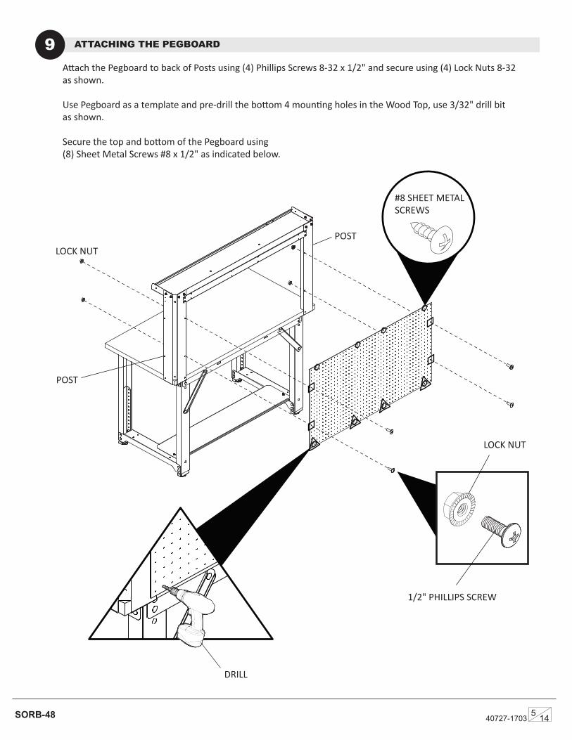
Attach the Pegboard to back of Posts using (4) Phillips Screws 8-32 x 1/2" and secure using (4) Lock Nuts 8-32 as shown.
Use Pegboard as a template and pre-drill the bottom 4 mounting holes in the Wood Top, use 3/32" drill bitas shown.
Secure the top and bottom of the Pegboard using (8) Sheet Metal Screws #8 x 1/2" as indicated below.
ATTACHING THE PEGBOARD9
SORB-48 40727-17035 14
POST
POST
DRILL
1/2" PHILLIPS SCREW
LOCK NUT
LOCK NUT
#8 SHEET METAL SCREWS
SECURING RELOADING BENCH TO WALL (IF MOUNTING TO FLOOR GO TO PAGE 7)10
40727-17036 14SORB-48
®
STACK-ON® PRODUCTS CO.P.O. BOX 489, WAUCONDA, IL 60084
For Customer Service help in the United States call: 1-800-323-9601
WALL STUDS
WOOD 2 x 4 CANNOT EXCEED 24”
WALL STUDS
WOOD2 x 4
MOUNTING HARWARENOT INCLUDED
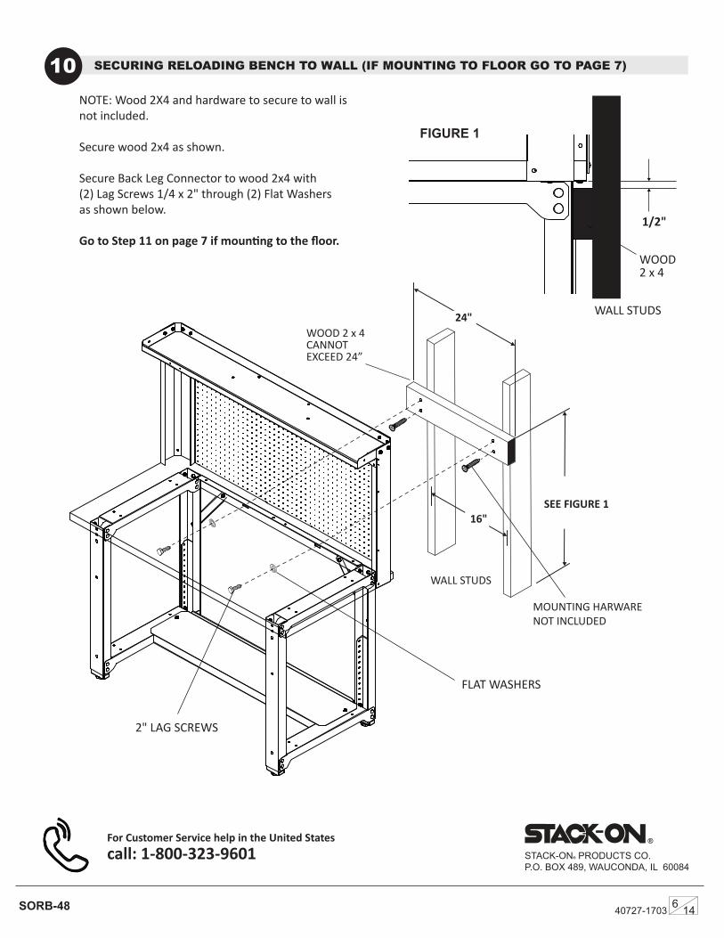
NOTE: Wood 2X4 and hardware to secure to wall is not included.
Secure wood 2x4 as shown.
Secure Back Leg Connector to wood 2x4 with (2) Lag Screws 1/4 x 2" through (2) Flat Washers as shown below.
Go to Step 11 on page 7 if mounting to the floor.
2" LAG SCREWS
FLAT WASHERS
FIGURE 1
24"
16"SEE FIGURE 1
1/2"
LOCK NUT
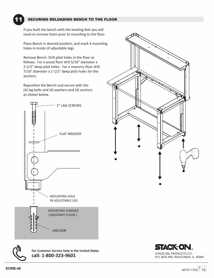
SECURING RELOADING BENCH TO THE FLOOR11
SORB-48
®
STACK-ON® PRODUCTS CO.P.O. BOX 489, WAUCONDA, IL 60084
For Customer Service help in the United States call: 1-800-323-9601
If you built the bench with the leveling feet you will need to remove them prior to mounting to the floor.
Place Bench in desired position, and mark 4 mounting holes in inside of adjustable legs.
Remove Bench. Drill pilot holes in the floor as follows: For a wood floor drill 5/16" diameter x 2-1/2" deep pilot holes. For a masonry floor drill 7/16" diameter x 2-1/2" deep pilot holes for the anchors.
Reposition the Bench and secure with the (4) lag bolts and (4) washers and (4) anchors as shown below.
40727-17037 14
2" LAG SCREWS
FLAT WASHER
ACHORS
MOUNTING SURFACE ( MASONRY FLOOR )
MOUNTING HOLE IN ADJUSTABLE LEG
ANCHOR
40727-17038 14SORB-48
®
ALTURA AJUSTABLE PRO BANCO DE RECARGA
SORB-48 INSTRUCCIONES
TABLA DE CONTENIDO
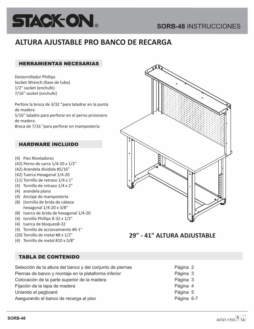
(4) Pies Niveladores(42) Perno de carro 1/4-20 x 1/2"(42) Arandela dividida #5/16" (42) Tuerca Hexagonal 1/4-20(11) Tornillo de retraso 1/4 x 1" (4) Tornillo de retraso 1/4 x 2" (4) arandela plana(4) Anclaje de mampostería(8) (tornillo de brida de cabeza hexagonal 1/4-20 x 3/8" (8) tuerca de brida de hexagonal 1/4-20 (4) tornillo Phillips 8-32 x 1/2" (4) tuerca de bloqueo8-32 (4) Tornillo de accionamiento #6-1" (20) Tornillo de metal #8 x 1/2"(4) Tornillo de metal #10 x 5/8"
HERRAMIENTAS NECESARIAS
Destornillador PhillipsSocket Wrench (llave de tubo)1/2" socket (enchufe)7/16" socket (enchufe)
Perfore la broca de 3/32 "para taladrar en la punta de madera 5/16" taladro para perforar en el perno prisionero de madera. Broca de 7/16 "para perforar en mampostería
Selección de la altura del banco y del conjunto de piernas Página 2Piernas de banco y montaje en la plataforma inferior Página 3Colocación de la parte superior de la madera Página 3Fijación de la tapa de madera Página 4 Uniendo el pegboard Página 5Asegurando el banco de recarga al piso Página 6-7
29" - 41" ALTURA ADJUSTABLE
HARDWARE INCLUIDO
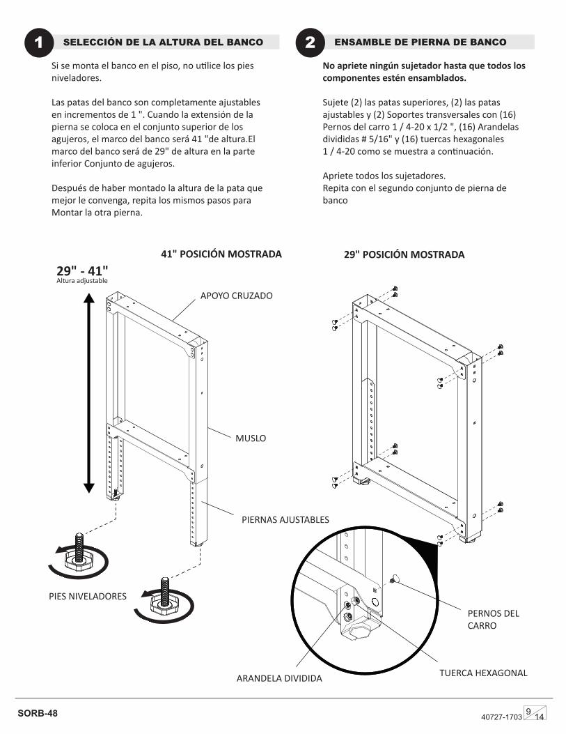
ARANDELA DIVIDIDA TUERCA HEXAGONAL
SORB-48
29" POSICIÓN MOSTRADA
Si se monta el banco en el piso, no utilice los pies niveladores.
Las patas del banco son completamente ajustables en incrementos de 1 ". Cuando la extensión de la pierna se coloca en el conjunto superior de los agujeros, el marco del banco será 41 "de altura.El marco del banco será de 29" de altura en la parte inferior Conjunto de agujeros.
Después de haber montado la altura de la pata que mejor le convenga, repita los mismos pasos para Montar la otra pierna.
SELECCIÓN DE LA ALTURA DEL BANCO1 No apriete ningún sujetador hasta que todos los componentes estén ensamblados.
Sujete (2) las patas superiores, (2) las patas ajustables y (2) Soportes transversales con (16) Pernos del carro 1 / 4-20 x 1/2 ", (16) Arandelas divididas # 5/16" y (16) tuercas hexagonales 1 / 4-20 como se muestra a continuación.
Apriete todos los sujetadores.Repita con el segundo conjunto de pierna de banco
ENSAMBLE DE PIERNA DE BANCO2
41" POSICIÓN MOSTRADA
40727-17039 14
PIES NIVELADORES
MUSLO
APOYO CRUZADO
PIERNAS AJUSTABLES
PERNOS DEL CARRO
29" - 41" Altura adjustable
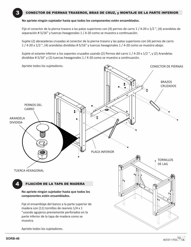
No apriete ningún sujetador hasta que todos los componentes estén ensamblados.
Fije el conector de la pierna trasera a las patas superiores con (4) pernos de carro 1 / 4-20 x 1/2 ", (4) arandelas de separación # 5/16" y tuercas hexagonales 1 / 4-20 como se muestra a continuación.
Sujete (2) abrazaderas cruzadas al conector de la pierna trasera y las patas superiores con (4) pernos de carro 1 / 4-20 x 1/2 ", (4) arandelas divididas # 5/16" y tuercas hexagonales 1 / 4-20 como se muestra abajo.
Sujete el estante inferior a los soportes cruzados usando (2) Pernos del carro 1 / 4-20 x 1/2 ", y (2) Arandelas divididas # 5/16" y (2) tuercas hexagonales 1 / 4-20 como se muestra a continuación.
Apriete todos los sujetadores.
SORB-48
CONECTOR DE PIERNAS TRASEROS, BRAS DE CRUZ, y MONTAJE DE LA PARTE INFERIOR3
No apriete ningún sujetador hasta que todos los componentes estén ensamblados.
Fije el ensamblaje del banco a la parte superior de madera con (11) tornillos de reenvío 1/4 x 1 "usando agujeros previamente perforados en la parte inferior de la tapa de madera como se muestra.
Apriete todos los sujetadores.
FIJACIÓN DE LA TAPA DE MADERA4
40727-17031014
PERNOS DEL CARRO
TUERCA HEXAGONAL
ARANDELA DIVIDIDA
TORNILLOS DE LAG
BRAZOS CRUZADOS
CONECTOR DE PIERNAS
PLACA INFERIOR
PERNOS DEL CARRO
SORB-48
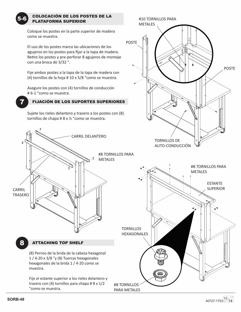
Coloque los postes en la parte superior de madera como se muestra.
El uso de los postes marca las ubicaciones de los agujeros en los postes para fijar a la tapa de madera. Retire los postes y pre-perforar 8 agujeros de montaje con una broca de 3/32 ".
Fije ambos postes a la tapa de la tapa de madera con (4) tornillos de la hoja # 10 x 5/8 "como se muestra.
Asegure los postes con (4) tornillos de conducción # 6-1 "como se muestra.
COLOCACIÓN DE LOS POSTES DE LA PLATAFORMA SUPERIOR5-6
ATTACHING TOP SHELF8
FIJACIÓN DE LOS SUPORTES SUPERIORES7Sujete los rieles delantero y trasero a los postes con (8) tornillos de chapa # 8 x ½ "como se muestra.
(8) Pernos de la brida de la cabeza hexagonal 1 / 4-20 x 3/8 "y (8) Tuercas hexagonales hexagonales de la brida 1 / 4-20 como se muestra.
Fije el estante superior a los rieles delantero y trasero con (4) tornillos para chapa # 8 x 1/2 "como se muestra.
40727-170311 14
#10 TORNILLOS PARA METALES
TORNILLOS DE AUTO-CONDUCCIÓN
#8 TORNILLOS PARA METALES
TORNILLOS HEXAGONALES
POSTE
CARRIL DELANTERO
CARRILTRASERO
ESTANTE SUPERIOR
POSTE
#8 TORNILLOS PARA METALES
#8 TORNILLOS PARA METALES
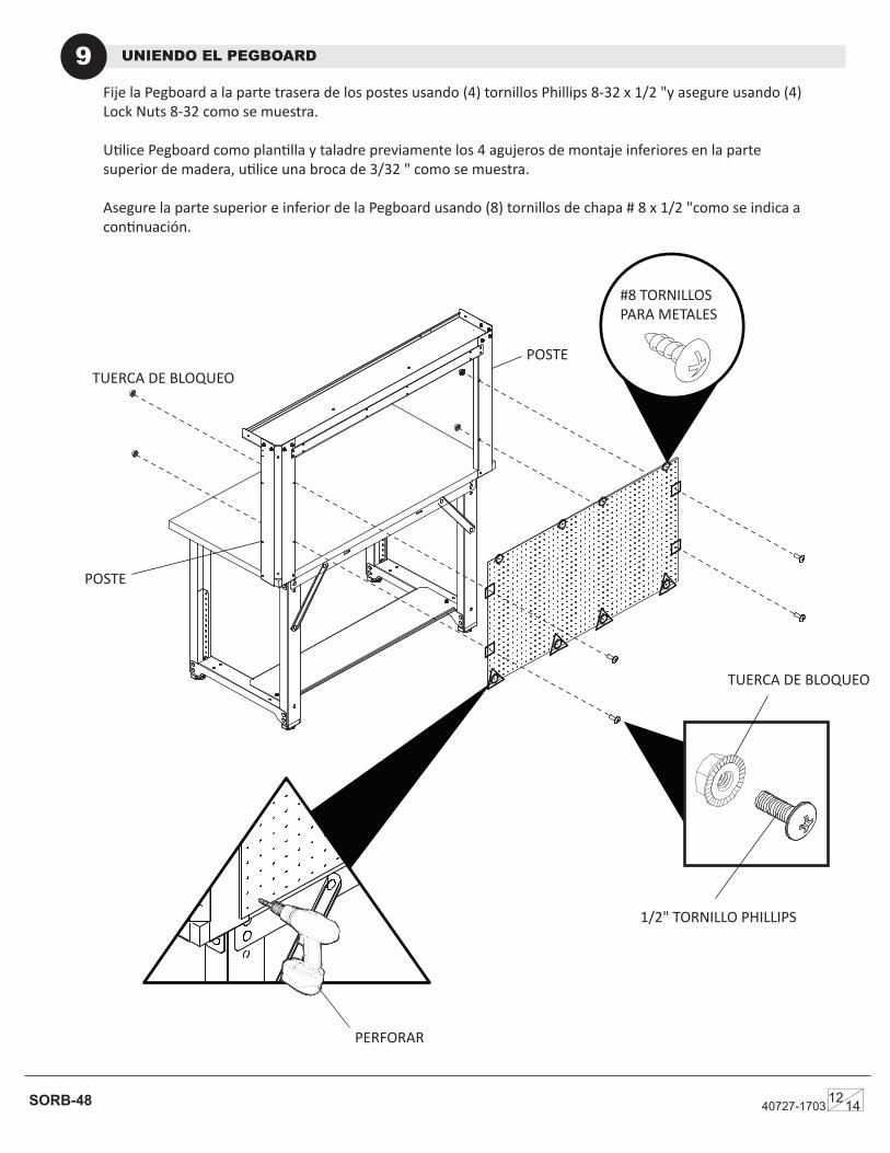
Fije la Pegboard a la parte trasera de los postes usando (4) tornillos Phillips 8-32 x 1/2 "y asegure usando (4) Lock Nuts 8-32 como se muestra.
Utilice Pegboard como plantilla y taladre previamente los 4 agujeros de montaje inferiores en la parte superior de madera, utilice una broca de 3/32 " como se muestra.
Asegure la parte superior e inferior de la Pegboard usando (8) tornillos de chapa # 8 x 1/2 "como se indica a continuación.
UNIENDO EL PEGBOARD9
SORB-48 40727-17031214
POSTE
POSTE
PERFORAR
1/2" TORNILLO PHILLIPS
TUERCA DE BLOQUEO
TUERCA DE BLOQUEO
#8 TORNILLOS PARA METALES
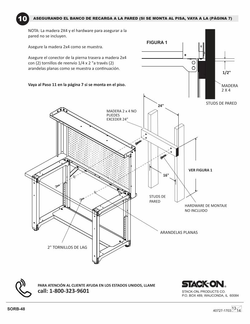
FIGURA 1
ASEGURANDO EL BANCO DE RECARGA A LA PARED (SI SE MONTA AL PISA, VAYA A LA (PÁGINA 7)10
40727-17031314SORB-48
®
STACK-ON® PRODUCTS CO.P.O. BOX 489, WAUCONDA, IL 60084
PARA ATENCIÓN AL CLIENTE AYUDA EN LOS ESTADOS UNIDOS, LLAMEcall: 1-800-323-9601
STUDS DE PARED
MADERA 2 x 4 NO PUEDESEXCEDER 24”
STUDS DE PARED
MADERA 2 X 4
HARDWARE DE MONTAJE NO INCLUIDO
NOTA: La madera 2X4 y el hardware para asegurar a la pared no se incluyen.
Asegure la madera 2x4 como se muestra.
Asegure el conector de la pierna trasera a madera 2x4 con (2) tornillos de reenvío 1/4 x 2 "a través (2) arandelas planas como se muestra a continuación.
Vaya al Paso 11 en la página 7 si se monta en el piso.
2" TORNILLOS DE LAG
ARANDELAS PLANAS
24"
16"VER FIGURA 1
1/2"
TUERCA DE BLOQUEO
ASEGURANDO EL BANCO DE RECARGA AL PISO11
SORB-48
®
STACK-ON® PRODUCTS CO.P.O. BOX 489, WAUCONDA, IL 60084
PARA ATENCIÓN AL CLIENTE AYUDA EN LOS ESTADOS UNIDOS, LLAMEcall: 1-800-323-9601
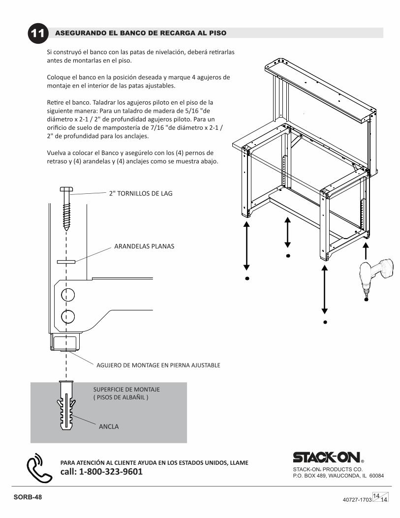
Si construyó el banco con las patas de nivelación, deberá retirarlas antes de montarlas en el piso.
Coloque el banco en la posición deseada y marque 4 agujeros de montaje en el interior de las patas ajustables.
Retire el banco. Taladrar los agujeros piloto en el piso de la siguiente manera: Para un taladro de madera de 5/16 "de diámetro x 2-1 / 2" de profundidad agujeros piloto. Para un orificio de suelo de mampostería de 7/16 "de diámetro x 2-1 / 2" de profundidad para los anclajes.
Vuelva a colocar el Banco y asegúrelo con los (4) pernos de retraso y (4) arandelas y (4) anclajes como se muestra abajo.
40727-17031414
2" TORNILLOS DE LAG
ARANDELAS PLANAS
ACHORS
SUPERFICIE DE MONTAJE( PISOS DE ALBAÑIL )
AGUJERO DE MONTAGE EN PIERNA AJUSTABLE
ANCLA