Embed Size (px)
Citation preview

Graduate Theses, Dissertations, and Problem Reports
2016
Adjustment of Bracket Position Away From the Andrew's Plane to Adjustment of Bracket Position Away From the Andrew's Plane to
Achieve a Flat Occlusal Plane Achieve a Flat Occlusal Plane
Jason M. Lawrence
Follow this and additional works at: https://researchrepository.wvu.edu/etd
Recommended Citation Recommended Citation Lawrence, Jason M., "Adjustment of Bracket Position Away From the Andrew's Plane to Achieve a Flat Occlusal Plane" (2016). Graduate Theses, Dissertations, and Problem Reports. 6045. https://researchrepository.wvu.edu/etd/6045
This Thesis is protected by copyright and/or related rights. It has been brought to you by the The Research Repository @ WVU with permission from the rights-holder(s). You are free to use this Thesis in any way that is permitted by the copyright and related rights legislation that applies to your use. For other uses you must obtain permission from the rights-holder(s) directly, unless additional rights are indicated by a Creative Commons license in the record and/ or on the work itself. This Thesis has been accepted for inclusion in WVU Graduate Theses, Dissertations, and Problem Reports collection by an authorized administrator of The Research Repository @ WVU. For more information, please contact [email protected].

Adjustment of Bracket Position Away From the
Andrew’s Plane to Achieve a Flat Occlusal Plane
Dr. Jason M Lawrence
Thesis submitted to School of Dentistry, Department of Orthodontics
at West Virginia University
in partial fulfillment of the requirments for the degree of
Master of Science in
Orthodontics
Peter Ngan D.M.D. M.S., Chair
Chris Martin D.D.S. M.S.
Richard Jurevic D.D.S. Ph.D.
Department of Orthodontics
Morgantown, West Virginia
2016
Keywords: Brackets, Sighting, Curve of Spee, Occlusal Plane, Occlusion
Copyright 2016 Jason Lawrence

ABSTRACT
“Adjustment of Bracket Position Away From the
Andrew’s Plane to Achieve a Flat Occlusal Plane.” Dr. Jason Lawrence
Background: “The Six Keys to Normal (Optimal) Occlusion” published by Andrews in 1972 identified
six common features characteristic of an optimal occlusion. Among these characteristics are flat
maxillary and mandibular occlusal planes. Andrews further developed the Straight-Wire Appliance™ to
facilitate attaining an optimal occlusion in an efficient manner with few if any arch wire bends. In
addition to the Six Keys, Andrews proposed that attaining a flat occlusal plane with a straight arch wire is
predicated on siting the bracket slots on the FA Points of the tooth crowns (Andrews Plane). Observation
of the maxillary and mandibular Andrews plane will reveal that these two planes diverge when both
occlusal planes are levelled. This may be attributed to a proportional height discrepancy between the
tooth crowns; which requires an adjustment to the sited vertical position of the slots on certain tooth
crowns.
Objective: The purpose of this study was to investigate if there is a need to adjusted the FA Points on
certain maxillary and mandibular tooth crowns to permit a flat parabolic shaped arch wire to produce
level slot alignment and a flat occlusal plane. Correlations between the tooth crown heights and FA Point
discrepancies were also analyzed.
Materials and Methods: Casts of twenty patients were scanned and virtually treated using software
(ORTHO INSIGHT 3D version 6.0.7036, Motionview Software, LLC). Crown heights of all maxillary
and mandibular teeth were digitally measured and recorded. Each sample case was treated virtually to
precise level slot alignment with the brackets sited on the FA Points as defined by Andrews. A second
treatment was virtually completed on these cases where a flat occlusal plane was not attained with the
initial virtual treatment. Bracket positions were adjusted vertically as needed on certain tooth crowns to
permit level slot alignment and a flat occlusal plane. The required height adjustment required to attain
level slot alignment were recorded as a + or – vertical height discrepancy between Andrews FA Point and
the “adjusted FA Point”. Normative statistics was generated for all tooth heights, FA Points, and FA
Point discrepancies. Correlations analyses were performed between tooth crown heights, FA Points, and
FA Point discrepancies.
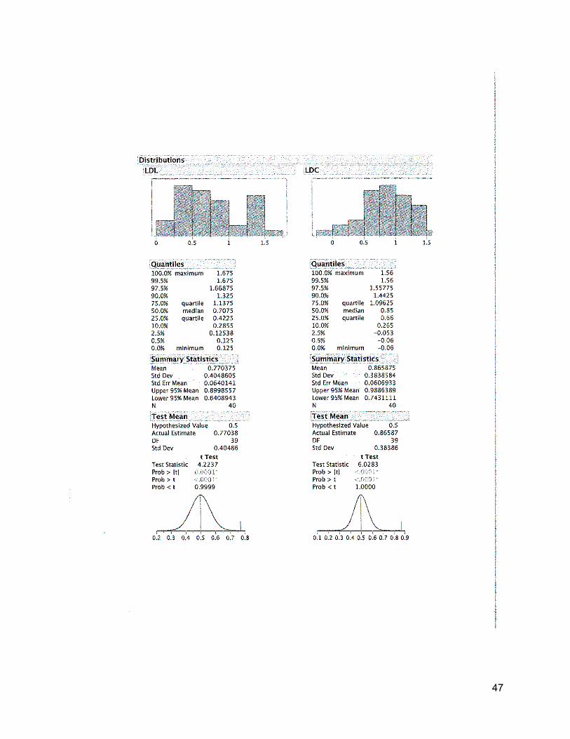
Results and conclusions: Mx centrals will likely require an adjustment to the incisal edge of at least
0.5mm ( avg.=1.23 p=<0.0001) Mx laterals will show a positive correlation with crown height and incisal
adjustment though not likely to require a change greater than 0.5 mm(avg=0.43mm p=. Md incisors will
require an adjustment greater than 0.5mm (laterals avg =0.77mm p=0.0001 centrals avg=0.87mm
p=<0.0001) Proclination of lower incisors do not yield a significant change from previously discovered
adjustment (lateral avg= 1.34mm p=<0.0001 central avg=1.04mm p=<0.0001) retroclining lower incisors
requires no significant adjustment from FA (lateral avg=-0.23mm p=<0.0001 central avg=-0.27mm
p=<0.0001) all other teeth found no significant need for occlusal or gingival adjustment.

iii
Contents
Abstract....................................................................................................................................... ii
Chapter 1: Introduction ............................................................................................................... 1
Background: ........................................................................................................................... 1
The Problem ........................................................................................................................... 3
Glossary ................................................................................................................................. 4
Goals ...................................................................................................................................... 5
Limitations .............................................................................................................................. 5
Delimitations ........................................................................................................................... 5
Assumptions ........................................................................................................................... 6
Chapter 2: Review of the Literature. ........................................................................................... 6
Notable Variations in Dental anatomy. .................................................................................... 6
Straight wire appliance theory and back ground ..................................................................... 8
Optimal Occlusion .................................................................................................................10
Six Keys to optimal occlusion .............................................................................................10
Straight wire appliance practice and application ....................................................................13
Bracket siting as a clinical execution .....................................................................................14
Significance ..............................................................................................................................17
Null Hypothesis .........................................................................................................................17
Materials and Methods: .............................................................................................................18
Materials ................................................................................................................................18
Methods ................................................................................................................................18
Statistical analysis .................................................................................................................26
Results ......................................................................................................................................26
Discussion ................................................................................................................................28
Conclusions ..............................................................................................................................31
References ...............................................................................................................................32
Appendicies ..............................................................................................................................35
Appendix A: Variable Definitions............................................................................................36
Appendix B Data ...................................................................................................................37
Appendix C Statistical analyss ...............................................................................................40
Appendix D Research ethics .................................................................................................50

1
Chapter 1: Introduction
Background:
Dr. Angle was one of the first dentists to develop appliances that applied forces to the
dentition in an attempt to correct for crowding and mal occlusions; he developed a number of
different mechanisms until he finally landed on the Edgewise appliance. After Dr. Angle began
the process of developing treatment techniques two main philosophies dominated the orthodontic
world, Begg light wire and Tweed edgewise. These two philosophies were developed for an
almost exclusively non extraction technique that followed in the same line of thought as
Angle’s.20
With the traditional edgewise appliance brackets were placed at a determined position
from occlusal or incisal edges of the dentition. Any discrepancy in height, prominence,
angulation, or inclination was corrected with first, second, and third order bends. This made for a
highly effective yet subjective, tedious, and inefficient application of the art and science of
orthodontics. The edgewise appliance remained unchanged for several decades until the work of
Dr. Andrews approached the concept of using a twin bracket from a new perspective and built on
the idea of the partially programmed appliance.20
Larry Andrew’s straight wire appliance (SWA) is often compared to Angle’s edgewise
appliance, or considered a variation of the edgewise appliance. This comparison is a bit flawed
because the edgewise appliance relied on the practitioner to impose the proper tip, torque,
angulation, rotation, and prominence. The brackets of the Edgewise appliance are universal;
meaning no regard for specific teeth is given to the selection of a bracket. By contrast the SWA
contains customized brackets for each tooth type, pre angulation slots that impose proper

2
angulation to the tooth if the bracket is sited squarely on the facial surface, bases of these
brackets are contoured occlusogingivally and mesiodistally to allow for proper fit to the facial
axis point on the labial surface of each tooth, bases of the brackets are angulated so as to
communicate proper tip/torque to each tooth, and bracket bases are designed uniquely to impart
proper prominence. Outside of the twin bracket design, use of an edgewise wire, and the
rectangular slot very little similarities with traditional edgewise appliances exist.3 The SWA has
become so prominent that nearly every orthodontist in the world now uses some variation of the
appliance.
The fully programmed nature of the SWA requires that the prescription be expressed
from the same location on every tooth known as the Facial Axis (FA) point.3 the FA point lies on
a plane that is similar to, but not exactly parallel to the occlusal plane of each arch (fig. 1). This
results in two Andrews planes, one for each arch. These planes diverge from each other as they
travel anteriorly.
Fig.1 Illustration of
properly positioned
brackets on Facial Axis
points. Notice that the
occlusal planes
converge anteriorly
allowing for the
Andrews planes to
assume a parallel
orientation.
3
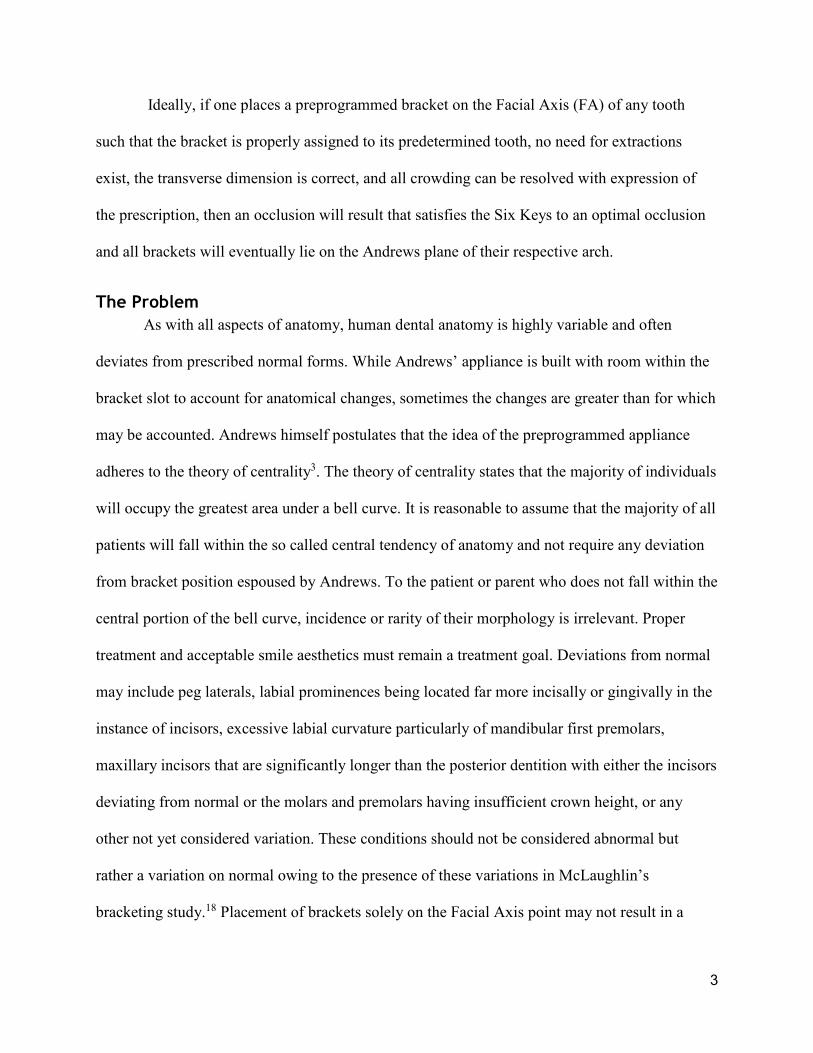
Ideally, if one places a preprogrammed bracket on the Facial Axis (FA) of any tooth
such that the bracket is properly assigned to its predetermined tooth, no need for extractions
exist, the transverse dimension is correct, and all crowding can be resolved with expression of
the prescription, then an occlusion will result that satisfies the Six Keys to an optimal occlusion
and all brackets will eventually lie on the Andrews plane of their respective arch.
The Problem
As with all aspects of anatomy, human dental anatomy is highly variable and often
deviates from prescribed normal forms. While Andrews’ appliance is built with room within the
bracket slot to account for anatomical changes, sometimes the changes are greater than for which
may be accounted. Andrews himself postulates that the idea of the preprogrammed appliance
adheres to the theory of centrality3. The theory of centrality states that the majority of individuals
will occupy the greatest area under a bell curve. It is reasonable to assume that the majority of all
patients will fall within the so called central tendency of anatomy and not require any deviation
from bracket position espoused by Andrews. To the patient or parent who does not fall within the
central portion of the bell curve, incidence or rarity of their morphology is irrelevant. Proper
treatment and acceptable smile aesthetics must remain a treatment goal. Deviations from normal
may include peg laterals, labial prominences being located far more incisally or gingivally in the
instance of incisors, excessive labial curvature particularly of mandibular first premolars,
maxillary incisors that are significantly longer than the posterior dentition with either the incisors
deviating from normal or the molars and premolars having insufficient crown height, or any
other not yet considered variation. These conditions should not be considered abnormal but
rather a variation on normal owing to the presence of these variations in McLaughlin’s
bracketing study.18 Placement of brackets solely on the Facial Axis point may not result in a

4
leveled Curve of Spee. When such a discrepancy is present, especially since the maxillary and
mandibular Andrews planes can be observed to diverge when the occlusal planes of the
respective arches are level, or there remains a Curve of Spee maintained on the lower arch and an
reverse curve on the upper arch, An adjustment to the bracket location must be employed to
account for this naturally occurring discrepancy. This exploration chooses to focus on innate
height discrepancy between posterior and anterior dentition. To date, no study has examined
whether a deviation from the ideal FA point on the clinical crown is acceptable or even desirable.
Glossary
• Curve of Spee: the curvature of the mandibular occlusal plane beginning at the tip of the
lower incisors and following the buccal cusps of the posterior teeth, continuing to the
terminal molar.
• Facial Axis of the Clinical Crown(FACC): the long axis of any tooth that is centered
mesio-distal on the facial surface of the clinical crown. Exeptions are the molars where
the FACC is defined as the line running down the buccal groove of the clinical crown.
• Facial Axis Point(FA): the midpoint of the FACC that is meant as the optimal location
for bracket placement.
• Occlusal plane: a plane passing through the occlusal or biting surfaces of the teeth. It
represents the mean of the curvature of the occlusal surface. Also called biteplane.
• Andrews Plane: a plane created by the FA points of a level arch. One plane exists for the
mandible and one for the maxilla. These planes may or may not be level with the occlusal
plane

5
Goals
• Determine average heights of clinical crowns that exhibit a height discrepancy from
posterior to anterior
• Determine if vertical proportion of dentition should affect bracket positioning.
• Evaluate proper bracket position in the presence of an increase vertical dimension of
the anterior dentition in relation to the posterior dentition.
• Determine a predictable technique for determining proper bracket position outside of
clinical judgment.
Limitations
- Human error in construction of ideal occlusal planes
- Computer distortion of scanned casts
- Lack of consensus on ideals for perfect dentition concerning angulation and inclination
- Prescription will be expressed regardless of periodontal limitations.
- Current technological capabilities are limited in accuracy and execution of occlusion from
scanned models
- Statistical occurrence of height discrepancy not explored.
Delimitations
- All virtual treatments will be designed by the same operator using the same software.
- Only one prescription will be referenced when initially aligning the dentition

6
Assumptions
-Flat occlusal plane is optimal
-Computer modeling accurately predicts bracket expression
- Flat occlusal plane with no rotations, crowding, spacing, extremes in angulation or inclination
will yield an ideal occlusion.
Chapter 2: Review of the Literature.
Notable Variations in Dental anatomy.
The human dentition is prone to significant anatomical variation, and while normal forms
do exist many teeth fall within the realm of a variation from normal. Even if all dentition is
studied from a single ethnic group considerable variability in dental morphology is present. 35
Variants may occur in facial curvature, crown width, crown height, or number of developmental
lobes. Sometimes these variations occur all at once or individually. A brief discussion of some of
the more notable morphological variations of the dentition follows. This examination is limited
to serve the purposes of this investigation only and does not represent an exhaustive recollection
of all morphological variables.
The maxillary central incisor is wedge shaped when viewed from the facial aspect.
Crown length of the central can but does not always correspond with root length. The tooth is
always formed by four developmental lobes, three that make up the facial aspect and one that
forms the cingulum. Sometimes the middle lobe becomes obliterated if the two lateral lobes are
oversized and absorb the middle one.35 An examination of the height of contour of the labial
aspect finds that the most facially prominent point is located in the middle third of the crown and
corresponds to the facial axis point roughly 80% of the time.31 This means that in 20% of cases

7
the most prominent point will not coincide with the FA point and will result in a different
expression of the appliance prescription.
Variability of Maxillary lateral incisors is well documented. 29 These teeth are typically
more rounded at the point angles than are their central counterparts. Sometimes they are
malformed enough to constitute as pegged laterals where developmental lobes have either never
formed or all fused into a single lobe.29 Often these teeth present clinically with a mesially tipped
crown forming an almost boot shape with the mesio-incisal point angle being significantly more
incisal than the disto-incisal. The disto-incisal point angle is often so rounded as to be nearly
obliterated. The variability of the lateral incisor disposes it to a study solely concerned with
siting brackets on this tooth; however it will be included in this study on a purely inciso-gingival
basis.
Mandibular first premolars present with their own unique variations particularly of the
labial surface. These members of the dentition exhibit the greatest amount of labial curvature in
the dentition hence making the more prone to torsional forces when bracket slot heights are
varied. A study by Sardarian et al found that torque forces in a more incisal position produce
decrease as one positions a slot more gingival until the slot is roughly 4.5 mm from the incisal
edge. Once past this point forces increase rapidly.29
Mandibular first Molars all form from five lobes and typically fall within two
morphological categories as evidences by Doo Eun Park et al in their study concerning first
molar morphology. This study showed that the two morphological types both fall within the
tolerances of designated prescriptions. This means that only in extreme cases do variations in
bracket position need to be employed concerning Mandibular first molars.29

8
Straight wire appliance theory and back ground
In an attempt to eliminate the need for finishing bends Dr. Larry Andrews studied 120
untreated optimal cases. Through records of these cases Dr. Andrews was able to arrive at
normal values for inclination, angulation, prominence, and relationship of the arches concerning
intercupsation and curve of Spee for every tooth within a dentition2
From these normal values Dr. Andrews was able to record and articulate the six keys to a
normal occlusion. The straight wire appliance was developed with the six keys programmed into
the bracket in an attempt to simplify the orthodontic treatment process. Simplification of
orthodontic process was only one motivation, Dr. Andrews also noticed great variation in
treatment goals and results amongst the American Board of Orthodontics approved cases.5 Any
significant variation is troubling when trying to establish ideals thus a need for clear treatment
goals was needed.
The concept of a straight wire appliance relies upon the prescription contained within the
bracket being properly expressed from the FA point. The FA is defined as the center Facial axis
of the clinical crown (FACC). Andrews defined the FACC as the central line of the anatomical
crown often comprising the remnants of the central developmental lobe. Ideally the FA point will
also coincide with the most prominent aspect of the facial surface (the height of contour) of the
tooth so that the prescription is expressed optimally.4 In order for the bracket prescription to be
expressed properly three points must all align: the FA point, the base of the bracket and the base
of the slot. (Fig. 2) To accomplish this coordination any required torque needed to be expressed
in the base of the bracket as opposed to the slot.4

9
If all brackets are expressed properly, then at the conclusion of treatment all brackets will
fall on a plane created by a line drawn between all FA points. This line indicates the Andrews
plane as previously discussed.5
Dr. Andrews conducted further analysis on other cases that exemplified orthodontic
ideals. From this later analysis the six elements of orofacial harmony were derived. For purposes
of brevity and relevance only the sixth element dealing with occlusion will be reviewed.
Fig.2
Illustration of
consequences to
torque in slot vs.
torque in base.
10
Optimal Occlusion
Optimal occlusion involves: the Six Keys to Optimal Occlusion (fig. 3), Element I teeth and
arches, and the Element II, III, and IV jaw positions. Collectively, these are the characteristics of
an esthetic, functional, and healthy occlusion. This particular study focuses on the impacts of the
Sixth Element and in particular the Sixth key of the Sixth element.
Six Keys to optimal occlusion
The SWA was not the only result of Andrews labors. In fact several years prior to the
development of the SWA Andrews used the initial 120 untreated patients along with 1105 treated
patients to identify all of the aspects that made these occlusions so desirable. He Devised six
aspects of occlusion that were all shared by these natural and optimally treated occlusion that
later became known as the six keys to normal occlusion. A brief summary of the six keys to
optimal occlusion is necessary to properly describe the treatment objectives pursued by this
study.
Key I. Molar relationship.
The first of the six keys is molar relationship. The natural occlusion models consistently
demonstrated that the distal surface of the distobuccal cusp of the upper first permanent molar
occluded with the mesial surface of the mesiobuccal cusp of the lower second molar. Simply
judging occlusion by the Mesiobuccal cusp of the Maxillary first molar in occlusion with the
buccal grove of the mandibular first molar is insufficient since a malocclusion may still exist
even with this relationship intact. A mesial angulation of the maxillary first molar is required for
proper key I relationship to be achieved.2
Key II. Crown angulation (tip).
When the casts were studied it was determined that the gingival portion of the long axes
of all crowns was more distal than the incisal portion. Crown tip is expressed in degrees, positive

11
or negative. The degree of crown tip is the angle between the long axis of the crown and a line
bearing 90 degrees from the occlusal plane. A positive angulation is determined when the
gingival portion of the long axis of the crown is distal to the incisal portion. A negative
angulation is assigned when the gingival portion of the long axis of the crown is mesial to the
incisal portion. Each natural optimal model consistently had a distal inclination of the gingival
portion of each crown. It varied with each tooth type, but within each type the angulation pattern
was consistent from individual to individual.2
Key III. Crown inclination (labiolingual of buccolingual inclination).
Crown inclination is expressed in positive or negative degrees, representing the angle
formed by a line which bears 90 degrees to the occlusal plane and a line that is tangent to the
bracket site or Facial Axis point. A positive inclination is given if the gingival portion of the
tangent line is lingual to the incisal portion. A negative inclination is recorded when just the
opposite of the previous circumstance is present. Upper and lower anterior crown inclinations are
intricately complementary and significantly affect overbite and posterior occlusion. Properly
inclined anterior crowns contribute to normal overbite and posterior occlusion, when occlusal
stops are eliminated by too negative of an inclination function is disrupted and over eruption is
results. When anterior crowns are properly inclined the posterior teeth are encouraged into their
normal positions. Even when the upper posterior teeth are in proper occlusion with the lower
posterior teeth, spaces will result somewhere between the anterior and posterior teeth if the
inclination of the anterior crowns is too positive. Crowding will result if inclination is too
negative.
The pattern of upper posterior crown inclination was consistent in the naturally optimal
models. A negative crown inclination existed in each crown from the upper canine through the
upper second premolar. The lower posterior crown inclination pattern also was consistent among
12
all the untreated normal models. 2
Key IV. Rotations.
The fourth key to optimal occlusion is that the teeth should be free of rotations.2
Key V. Tight contacts.
The fifth key is that the contact points should be tight (no spaces). Tooth size
discrepancies pose special challenges to this key however in the absence of such a discrepancy
all contacts should be tight. Without exception, the contact points on the untreated models were
tight. 2
Key VI. Occlusal plane.
The planes of occlusion found on the untreated models ranged from flat to slight curves
of Spee. Even though not all of the untreated models had flat planes of occlusion, a flat plane
should be a treatment goal as a form of overtreatment. There is a natural tendency for the curve
of Spee to deepen with time, as the mandible continues its growth forcing the lower anterior
dentition into a narrower aspect of the upper dentition resulting un up righting and deepening of
the curve of Spee. Intercuspation of teeth is best when the plane of occlusion is relatively flat. A
deep curve of Spee results in a more contained area for the upper teeth, making normal occlusion
impossible. 2
13
The ABO uses these keys to grade cases and while no specific requirement for a flat
occlusal plane is present, there are standards for inclination, overjet, over bite, angulation,
interproximal contact, and occlusion. Tthese criteria combined are very difficult if not impossible
to achieve with an occlusal plane that deviates from the slight to flat ideal set forth by Andrews.
Straight wire appliance practice and application
Precise placement of an orthodontic bracket by hand is a difficult task. Though Dr.
Andrews asserts the capability of the human eye to precisely dissect the anatomy of a tooth and
locate the FA point, errors still occur. These errors may be attributed to operator error, variance
in anatomy, or both. Proffit has espoused the benefits of the straight wire appliance while also
noting the necessity for finishing bends.29 All pre-programmed appliances have built in “slop”
between the bracket and wire interface to allow for anomalous anatomy. The space allowed
between the bracket and the wire also allow for a less than precise placement of brackets. Owing
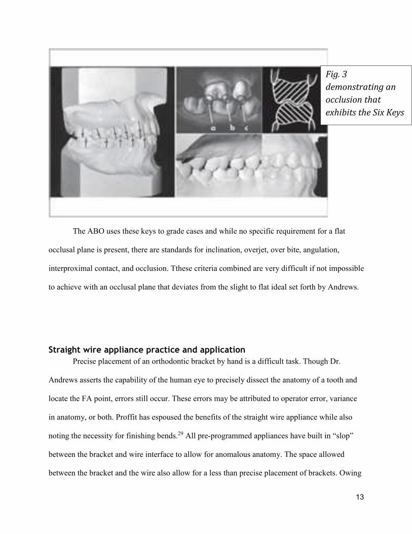
Fig. 3
demonstrating an
occlusion that
exhibits the Six Keys

14
to the difficulty of consistently and precisely placing brackets many devices, gauges, and stents
have been developed to aid Orthodontists when bonding a case with a straight wire
appliance.1,10,11,12,17,32 Many of these devices tend to lead the practitioner astray as exposed by
Suarez et al.33 Even with a programmed appliance, many orthodontists rely on first, second, and
third order bends for finishing cases, defeating the purpose of a straight wire appliance.
Some of the final discrepancies present in the dentition may in fact be due to a greater
height difference anteroposteriorly within the dentition than is allowed for in a prescription. This
is to say that expression from the FA points, even if perfectly positioned does not yield
satisfactory occlusal results. The final result is a non-ideal occlusal plane that is the result of
improper expression and not owing to improper placement. If a large enough height discrepancy
exist anteroposteriorly; then the Andrews plane must be adjusted incisally in order for a proper
expression of the prescription.
Bracket siting as a clinical execution
Sighting brackets has been part of clinical execution of the straight wire appliance since
the development of the SWA. Andrews asserts that the human eye can adequately identify the
midpoint of the clinical crown with no real need for measurements from any fixed location.4 This
has been proven in a study by Taylor et al found that bracket positioning in both the vertical and
horizontal dimensions was accurate and consistent. Bracketing positioning in the angular regards
however, is neither accurate nor reproducible.31

15
As mentioned previously determining bracket position was traditionally done from a
fixed location, but this has proven to result in unsatisfactory results with the SWA. Andrews
postulates that a visual dissection of the clinical crown is required to identify the midpoint
vertically and horizontally; the FA point. This approach to sighting brackets used anatomical
land marks and appearances to illuminate proper positioning for a bracket to express its
prescription. Some prominent clinicians still advocate for a fixed point reference for siting
brackets. Many still hold to the incisal edge as the ideal point to reference including
McLaughlin18 and Damon9 who both have published charts to reference proper bracket heights
from incisal edges. A study out of China recently confirmed that these bracketing charts do yield
satisfactory results when used for extraction cases.16
A study by McLaughlin et al determined average heights of FA points within a dentition
as well as the most common bracket sighting errors. This study found that it is uncommon for
clinicians to misidentify the FA of any dentition.18 The inclusion criteria did not allow for
significant anatomical variance that must occur within a clinical setting, for which an adjustment
must be made. Even within the sample size of Mclaughlin’s et al study the maximum half
clinical crown measurement of a Maxillary central (6.94mm) varied significantly from the
minimum clinical crown height of a Maxillary First molar (1.98mm)18 The result of this study
was the fabrication of a bracket sighting chart that uses a fixed value measured form the incisal
edge to the midpoint of the bracket to determine proper bracket height. A clinician may use this
chart coupled with clinical measurements of crown heights to adjust bracket position.
Unfortunately the previously mentioned recent study by Suarez et al explored marginal
ridge leveling when a fixed point method is used to site brackets. This study found that when a
fixed height was employed almost certainly marginal ridge discrepancies became worse. They

16
concluded that using a bracket siting chart would likely not result in any improvement in final
occlusion in fact it would likely only become worse.31 Thus the human eye remains the best
likely gauge for measuring proper bracket location.
Sound techniques for siting brackets must employ several strategies to ensure accuracy.
A clinician must be able to locate the FACC of a clinical crown; this will determine the
mesiodistal location. As mentioned previously the FACC runs the length of the clinical crown
along the remnants of the midfacial developmental lobe.4 The exception to this initial
identification technique is applied to the maxillary and mandibular molars where the buccal
grove serves as the FACC.4 A Line running the length of the buccal grove from the occlusal
terminus to the free gingival margin is identified. Once this mesiodistal determinant is identified
the occlusoginigval midpoint can be determined fairly accurately by simple observation. In order
to aid the clinician in identifying these land marks accurately the eye should be aligned squarely
with the facial surface of any tooth being sited.19 Viewing the facial surface from a view
perpendicular to the FACC helps to eliminate any parallax of the clinical crown. A direct view
should help the clinician determine the proper height and mesiodistal placement of a bracket, if
one employs a mouth mirror to view the occlusal aspect of the dentition any rotations of the
tooth of interest can be identified. The mouth mirror should be positioned the view the incisal or
occlusal aspect squarely just as the facial aspect was viewed. This view should help indicate the
long axis of the tooth, eliminate any distortion caused by rotations and thus increase the accuracy
of siting a bracket for angulation.35 As mentioned previously, angulation is the aspect that is
subject to the most error when siting brackets.
One must ask if any deleterious side effects may result from an adjustment in vertical
height with regards to final inclination, periodontal health, occlusion or smile aesthetics. As

17
mentioned previously the SWA allows for variation in anatomy that was demonstrated in the
study by R.N. Smith et al. when they identified that the most prominent point of the central
incisors coincides with FA only 80% of the time and only 50% when assessing maxillary lateral
incisors and Maxillary cuspids.31 The range of this tolerance must be explored to determine
effective bracket citing. Recently Rainer et al conducted a study and found that significant first
and third order changes occur based on the labial anatomy and bracket location particularly of
maxillary incisors. This study also showed that an adjustment either in the wire or bracket
location should be expected for satisfactory completion of treatment with a pre-adjusted
appliance(SWA)23 these findings are additionally reinforced by Van Loenen at al who
demonstrated that individualization in treatment on a case to case basis is absolutely necessary37.
Significance The significance of this research lies in determining the proper bracket height to achieve a level
occlusal plane. Should a consistent correction be discovered or a consistent rate of correction it
can help to finish cases with a higher compliance to the six keys of optimal occlusion.
Null Hypothesis No significant vertical adjustment in clinical crown height away from the FA point is required to
yield a flat occlusal plane.

18
Materials and Methods:
Materials
• One PC with sufficient processing and graphics generating power
• Two 24” monitors to facilitate data entry and measurement observation
• One motion view model scanner
• One licensed copy of Motion View proprietary software
• 20 dental case models
• Copy of Microsoft Excel to record data.
Methods
• 20 cases consisting of Maxillary and Mandibular. dental casts that were lacking any
significant anatomical variation (such as peg laterals or amelogenesis imperfect), having
a representation of a full adult dentition, free of restorations, free of cavitated carious
lesions, and of Caucasian individuals were scanned into a Personal computer using a
Motion View scanner with its proprietary software. All cases were deindivdualized by
assigning them a case number. N=40 considering each case contains two of each tooth.

19
• Scanned cases (fig. 4) had every tooth identified and separated virtually (fig 5)
• All teeth were measured along the central developmental lobe (FACC) (fig. 8) from cusp
tip/incisal edge to the free gingival margin. This constituted the heights of clinical
crowns. Exceptions to this measurement were the maxillary and mandibular molars. The
molars were measured along their buccal grove from the occlusal terminus to the free
gingival margin.
Fig. 4
showing
scanned
models.

20
• All necessary anatomical land marks were identified automatically by the software and
any corrections were applied by the operator. Particular attention was paid to marginal
ridge indicators. These dots will be located at the most concave point of its respective
marginal ridge. (fig. 6)
• Marginal ridges served as a key landmark for later adjustments. Marginal ridges were
chosen based on their inclusion in grading of ABO cases.
Fig. 5
Showing the
separation
of digitized
dentition.

21
• Following all of these identifying steps the computer was then capable of digitally
separating the clinical crowns from the model and manipulating the crown locations in
space. (fig. 7)
• After the teeth were digitized 6 color coded points are generated by the software.
• Measurements were automatically generated by the software providing
Fig 6.
Identification of
anatomical land
marks
Fig. 7
properly
digitized
and
identified
teeth that
coincide
with
originally
scanned
teeth.

22
• Distance of the mesial yellow dot to the red FA dot
• Distance of the distal yellow dot to the red dot
• Distance of the orange dot from the red dot
• The Red dot was dragged to the gingival limit of the clinical crowns along the FACC
• The Orange dot was placed at the inciso-facial line angle/mesio Buccal cusp tip/ occlusal
terminus of the buccal groove. This location was automatically decided by the computer
but confirmation was required by the operator.
• This provided the measurement of the FACC by taking advantage of the auto
measurement of the distance from the orange dot to the red dot – FACC Measurement
• All FACC values were recorded
• Excel division function was utilized to provide an FA point measurement we will call
anatomical FA. The FACC values were divided by 2. This measurement is accurate to
0.01 mm.
Fig. 8 Measurement of clinical crown along the FACC.

23
• the Andrews prescription was chosen as the reference prescription for auto alignment of
the crowns.
• The FA heights were designated for bracket placement on an individual case by case
basis. Heights were drawn from the excel spread sheet.
• An arch wire is generated and adjusted to form a straight line. The archwire is
straightened using the overlay grid feature of the software. (fig. 9)
• Auto alignment tool was engaged.
Fig. 9 Straight arch wire that will
align the clinical crowns.

24
• Any malposition concerning rotations or angulations present from the initial alignment
were corrected. Any dental overlap by location bugs were corrected.
• The alignment process began by aligning the mesial marginal ridge of the second molar
to the distal marginal ridge of the first molar. Mesiobuccal cusp tips were placed on the
same latitude for second molars as the first molars mesio buccal cusp. Then marginal
ridges of the premolars were coordinated to the first molar. This established the occlusal
plane. Most mesial premolar with aligned marginal ridges were referenced for its buccal
cusp height. This reference is only relevant if the cusp tips are of a different
height.(fig.10)
• The overlay mesh feature was activated. This provided a latitude to align the incisors
with the buccal cusp of the most mesial, aligned premolar.
• All incisors will be aligned with the reference cusp using the overlay mesh as a fixed
reference.
• Distal bulge of the cuspids aligned with mesial contact points of first premolars.
• The brackets were then be reapplied to the crowns in the corrected positions.
Reapplication of the bracket to the aligned teeth is a feature of motion view software.
This will move the FA point to the base of the bracket automatically allowing for the
scribe lines to indicate new vertical measurements. The bracket position is a reference to
the arch wire which has remained fixed in space during all adjustments to the clinical
crowns.
• After the brackets have been automatically re applied a new measurement from red dot to
the orange dot will be available. This measurement will be recorded and excel will

25
calculate the difference between red dot – orange dot measurement one (anatomical FA)
and red dot- orange dot measurement two (adjusted FA)
•
• After initial alignment, correction of digital errors, and simple measurements of newly
aligned crowns the mandibular incisors are selected and proclined en masse a total of 37
mouse clicks. This will result in a proclination of approximately 1mm. These same teeth
will then be tipped lingually 65 clicks to both compensate for initial proclination and
retrocline the dentition another 1mm.
• Retroclining adjustment will always be done from the proclined positions hence the need
to double the clicks for equal amount of adjustment.
• At the end of each proclination or retroclination step the teeth will be adjusted to the
occlusal plane as indicated by the same reference cusp. Brackets will again be reapplied
to aligned teeth and new FA measurments will be recorded.
Fig. 10
aligning of
the clinical
crowns
and
leveling of
the
occlusal
plane.

26
Statistical analysis
• A pilot study of 7 patients was completed and submitted to a statistician for power
analysis. The analysis revealed that for an alpha value greater than 0.90 9 samples must
be tested. This study consisted of 32 samples of each tooth giving an alpha of 0.99
• Averages and standard deviation of crown heights were obtained.
• Average and standard deviation of adjustment from anatomical FA were calculated.
• Simple hypothesis testing was engaged for all teeth to measure probability that an
adjustment greater than 0.5 mm is required in either direction.
• Correlation between crown height and bracket adjustment was explored to determine if a
specific height adjustment can be universally applied or if a rate of adjustment associated
with clinical crown height may be employed.
• Correlation between necessary proclination or retroclination and bracket adjustment were
also be analyzed in the same manner as
Results
Results were recorded with positive values indicating an adjustment toward the incisal or
occlusal surface and negative values representing an adjustment in the gingival direction. For
teeth numbers 2-7, 10-15, 18-22, and 27-31, no significant adjustment in vertical position away

27
from the FA point was found (p = 1.0000).
Table 1 shows the average adjustments for each tooth.
- For the maxillary centrals average adjustment incisally from FA point of 1.21 mm and a
probability of the adjustment being greater than 0.5 mm of nearly 100% (p = 1.000)
- For maxillary Laterals p= 0.8747 though the mean adjustment was 0.43 mm incisally
from FA
- For mandibular laterals average adjustment was 0.77 mm incisally with a p= <0.0001.
- For mandibular centrals an average adjustment of 0.87 mm incisally and a p= < 0.0001.
- Correlations for initial crown height to required adjustment were weak for many of the
teeth. However, for all incisors the correlation between necessary adjustment and initial
crown height was strong: 0.62 for lower laterals, 0.70 for lower centrals, 0.63 for upper
laterals and 0.50 for upper centrals.
-1
-0.5
0
0.5
1
1.5
2
UD2m UD2pm UDI UDC LDL LD1pm LD1m
Dis
tan
ce f
rom
FA
(m
m)
Average Adjustment from FATable 1
28
- Adjustments for lower incisors during proclination did not vary significantly from those
needed for a level occlusal plane. (avg adjustment 1.1 mm p=<0.0001for centrals and 1.3
mm for laterals p=<0.0001)
- Adjustments for retroclined lower incisors did not vary significantly from original FA.
Averaging -0.28mm for centrals p=1.000 and -0.24mm for laterals (p=1.000)
Discussion
For the majority of the teeth the adjustments required to achieve a level occlusal plain are
extremely small and not clinically relevant. For example, the maxillary second premolar required
a very small adjustment (-0.2mm) in the gingival direction; this could be attributed to initial
placement error or a very slight lack of eruption by the tooth. It is important to note that the
threshold for clinical relevance was set to 0.5 mm not just because of human ability to correct
such minor discrepancies, but also due to the ability of the appliance to express such small
adjustments. For these reasons the majority of adjustments are not considered relevant and the
null hypothesis is accepted.
Adjustments begin to be more significant as one travels anteriorly in the dental arch. The
maxillary laterals need an adjustment of greater than 0.5mm only 44% of the time though the
mean adjustment was 0.52 mm. This is likely due to a few cases of extremely long laterals
requiring large adjustments. The maxillary central is the most outstanding adjustment needed
with a mean of 1.28 mm. The probability of needing to adjust the bracket at least 0.5 mm was
29
close enough that one can say 100% of the time the bracket needs to be more incisal than FA. It
is important to note that among all of the maxillary teeth only the centrals required an adjustment
the majority of the time that was clinically significant and that adjustment was only in the incisal
direction.
The only maxillary tooth that consistently adjusted more gingival was the second molar. It is
probable that this adjustment was due to the tooth being slightly under erupted similar to the
second premolar; a theory that is further supported by the negative correlation present in the
clinical crown to bracket adjustment comparison seen in the results. A similar adjustment to the
maxillary central is required for all of the lower incisors where a mean incisal adjustment is
around 0.8mm and 0.76mm for centrals and lateral respectively. The probability of an adjustment
being required for a level occlusal plane was also significant for mandibular centrals and laterals
with p-values of 99.99% and 99.95% respectively.
These adjustments are required almost certainly because of the crown length exhibited by
these teeth. The correlation between crown height and necessary adjustment was strong for
Maxillary centrals, mandibular laterals, and mandibular centrals. ( 0.50 ,0.62, 0.70 respectively.)
Correlation for crown height and Maxillary laterals was also strong (0.63), but due to their
anatomical variability the probability of an adjustment being needed was very low only about
44% occurrence. The strong correlation is likely the result of average adjustment falling around
.5 mm. One would initially think that an average being clinically significant would make the
necessary sighting change significant, but again these teeth are highly variable. In the end
clinical judgment must prevail for Maxillary laterals.

30
For many patients ideal lower incisor inclination (-1⁰ to true vertical for the facial surface and
15⁰ to true vertical along the long axis.) is not attainable for proper anterior guidance and
coupling. The treatment may require proclination or retroclination depending on a class II or
class III skeletal relationship respectively. In such cases one should site brackets appropriately
depending on the desired final result. The brief exploration into any necessary adjustments
contained within this study reveals that in the cases of proclination the brackets should be
adjusted more incisal only slightly more than the height required for a flat occlusal plane. So
slight is the difference that clinical relevance is absent.
However the incisors required little to no adjustment when a retroclined mandibular anterior
was a desired treatment goal. When Lower incisors needed to be retroclined the bracket sighting
was very close to FA and in fact was approximately .2 mm more gingival than FA. This change
is not clinically significant however the placement is worth noting. The relationship of brackets
depends on the final inclination of the teeth and the brackets relationship to the center of
resistance. If a tooth needs to be more proclined and we imagine a fixed flat occlusal plane
represented by the wire (a more gingival translation but a parallel plane.) as the tooth rotates
anteriorly the fixed nature of the bracket height (fixed by the brackets of all other teeth) will
extrude the tooth. The opposite can be said for any incisor that needs to be retroclined. The fixed
nature of the occlusal plane and the movable nature of a center of resistance would tend to
intrude an incisor as it rotated more lingual.
It is important to understand that this study is not meant to result in a bracketing chart where
all patients are treated to a prescribed bracketing scheme. The purpose is to exhibit that variation
in bracket height is almost always necessary. When starting a case proper diagnosis will

31
absolutely inform the practitioner of proper bracket height. It is also important to note that this
study did not exam occlusal relationships in any way thus no bracket was ever significantly
adjusted more gingival from the FA. A clinician may find that open bites manifest as an
expression of an inharmonious skeletal relationship and may require bracketing on the FA, in the
instances of the maxillary and mandibular incisors, or gingival to the FA..
An astute clinician may voice concerns that differential bracketing will result in improper
inclinations or torque expression for incisors. Regarding this concern, it is important to
remember that a great deal of space exists between the wire and bracket interface. Often a
clinician must employ 45⁰ or more of torque in order to affect a small desired clinical change.
This allows for significant height changes without a significant affect in torque. In the end
clinical judgment must be employed when bracketing a case.
Conclusions
• Maxillary centrals should be adjusted at least 1mm incisally form FA in the majority of
cases
• Maxillary Laterals are highly variable but may only require adjustments in less than half
of the cases
• All Mandibular incisors require at least 0.5 mm adjustment incisaly for a flat occlusal
plane
• If mandibular incisors need proclined then the standard adjustment from FA (0.75mm)
will be sufficient.
• If mandibular incisors need retroclined then brackets should be placed on the FA.

32
References
1. Aggarwal, A., & Nayak, U. S. (2009). A new tool for orthodontic bracket placement.
Journal of Clinical Orthodontics : JCO, 43(4), 275.
2. Andrews, L. F. (1972). The six keys to normal occlusion. American Journal of
Orthodontics, 62(3), 296-309.
3. Andrews, L. F. (1976). The straight-wire appliance, origin, controversy, commentary.
Journal of Clinical Orthodontics : JCO, 10(2), 99-114.
4. Andrews, L. F. (1979). The straight-wire appliance. British Journal of Orthodontics, 6(3),
125-143.
5. Andrews, L. F. (1989). Straight wire: The concept and appliance (3rd ed.). San Diego,
CA: L.A. Wells Co.
6. Andrews, L. F. (Ed.). (2003). Straight wire: The concept and appliance (3rd ed.). San
Diego: L.A.Wells Co.
7. Aszkler, R. M., Preston, C. B., Saltaji, H., & Tabbaa, S. (2014). Long-term occlusal
changes assessed by the american board of orthodontics' model grading system.
American Journal of Orthodontics and Dentofacial Orthopedics : Official Publication of
the American Association of Orthodontists, its Constituent Societies, and the American
Board of Orthodontics, 145(2), 173-178. doi:10.1016/j.ajodo.2013.10.010 [doi]
8. Balut, N., Klapper, L., Sandrik, J., & Bowman, D. (1992). Variations in bracket
placement in the preadjusted orthodontic appliance. American Journal of Orthodontics
and Dentofacial Orthopedics : Official Publication of the American Association of
Orthodontists, its Constituent Societies, and the American Board of Orthodontics, 102(1),
62-67. doi:0889-5406(92)70015-3 [pii]
9. Damon, D. (2004). Bracket placment. In M. A. Bagden (Ed.), Damon system (pp. 129)
OrmcoCorperation.
10. Hattarki, R. S. (2013). A simple bracket placement gauge. International Journal of
Orthodontics (Milwaukee, Wis.), 24(3), 23-24.
11. Hattarki, R. S., & Malag, S. (2011). A modified bracket-positioning gauge. Orthodontics
: The Art and Practice of Dentofacial Enhancement, 12(3), 268-269.
12. Israel, M., Kusnoto, B., Evans, C. A., & Begole, E. (2011). A comparison of traditional
and computer-aided bracket placement methods. The Angle Orthodontist, 81(5), 828-835.
doi:10.2319/072110-425.1 [doi]
13. Jain, M., Varghese, J., Mascarenhas, R., Mogra, S., Shetty, S., & Dhakar, N. (2013).
Assessment of clinical outcomes of roth and MBT bracket prescription using the
american board of orthodontics objective grading system. Contemporary Clinical
Dentistry, 4(3), 307-312. doi:10.4103/0976-237X.118361 [doi]
14. Knosel, M., Jung, K., Gripp-Rudolph, L., Attin, T., Attin, R., Sadat-Khonsari, R., et al.
(2009). Changes in incisor third-order inclination resulting from vertical variation in
lingual bracket placement. The Angle Orthodontist, 79(4), 747-754. doi:10.2319/072308-
385.1 [doi]
15. Lai, M. L., & Mah, J. (2009). Precision of bracket placement on dental models. Journal
of Clinical Orthodontics : JCO, 43(8), 524-528.

33
16. Liu, D. X., Wang, C. L., Yue, J. R., & Zhang, X. Y. (2000). Study of bracket placement
with the preadjusted appliance for extraction cases. Shanghai Kou Qiang Yi Xue =
Shanghai Journal of Stomatology, 9(3), 141-142. doi:829 [pii]
17. Mazzeo, F., Marchese, E., Assumma, V., Sepe, J., & Perillo, L. (2013). A new device
(FAQ.FIX(R)) for orthodontic bracket placement in straight wire technique. Progress in
Orthodontics, 14, 23-1042-14-23. doi:10.1186/2196-1042-14-23 [doi]
18. McLaughlin, R. P., & Bennett, J. C. (1995). Bracket placement with the preadjusted
appliance. Journal of Clinical Orthodontics : JCO, 29(5), 302-311.
19. McLaughlin, R. P., & Bennett, J. C.; Trevisi, H. (1999) Practical Techniques for
Achieving Improved Accuracy in Bracket Positioning. Orthodontic Perspectives 6:1 21-
24.
20. McLaughlin, R. P., & Bennett, J. C. (2015). Evolution of treatment mechanics and
contemporary appliance design in orthodontics: A 40-year study. American Journal of
Orthodontics and Dentofacial Orthopedics : Official Publication of the American
Association of Orthodontists, its Constituent Societies, and the American Board of
Orthodontics, 147(6), 654-662.
21. Mestriner, M. A., Enoki, C., & Mucha, J. N. (2006). Normal torque of the buccal surface
of mandibular teeth and its relationship with bracket positioning: A study in normal
occlusion. Brazilian Dental Journal, 17(2), 155-160. doi:S0103-64402006000200014
[pii]
22. Meyer, M., & Nelson, G. (1978). Preadjusted edgewise appliances: Theory and practice.
American Journal of Orthodontics, 73(5), 485-498.
23. Miethke, R. R., & Melsen, B. (1999). Effect of variation in tooth morphology and bracket
position on first and third order correction with preadjusted appliances. American Journal
of Orthodontics and Dentofacial Orthopedics : Official Publication of the American
Association of Orthodontists, its Constituent Societies, and the American Board of
Orthodontics, 116(3), 329-335. doi:S0889-5406(99)70246-5 [pii]
24. Moesi, B., Dyer, F., & Benson, P. E. (2013). Roth versus MBT: Does bracket
prescription have an effect on the subjective outcome of pre-adjusted edgewise
treatment? European Journal of Orthodontics, 35(2), 236-243. doi:10.1093/ejo/cjr126
[doi]
25. Mohammadi, A., & Moslemzadeh, S. H. (2011). Comparison of the accuracy of bracket
placement with height bracket positioning gauge and boone gauge. Journal of Dental
Research, Dental Clinics, Dental Prospects, 5(4), 111-118. doi:10.5681/joddd.2011.026
[doi]
26. Park, D. E., Kim, H. K., Lim, Y. S., Nakatsuka, M., Kwon, H. B., Han, S. H., et al.
(2013). Different mandibular first molar shapes according to groove and cusp
configuration in relation to suggested bracket position. European Journal of
Orthodontics, 35(6), 730-736. doi:10.1093/ejo/cjs098 [doi]
27. Pontes, L. F., Cecim, R. L., Machado, S. M., & Normando, D. (2014). Tooth angulation
and dental arch perimeter-the effect of orthodontic bracket prescription. European
Journal of Orthodontics, doi:cju055 [pii]
28. Proffit, W. R., Fields, H. W. J., & Sarver, D. M. (1986). In John Dolan J. N. (Ed.),
Contemporary orthodontics (4th ed.). St. Louis, MO: Mosby Elsevier.
29. Roth, R. H. (1976). Five year clinical evaluation of the andrews straight-wire appliance.
Journal of Clinical Orthodontics : JCO, 10(11), 836-850.

34
30. Sardarian, A., Danaei, S., Shahidi, S., Boushehri, S., & Geramy, A. (2014). The effect of
vertical bracket positioning on torque and the resultant stress in the periodontal ligament-
a finite element study. Progress in Orthodontics, 15(1), 50. doi:s40510-014-0050-0 [pii]
31. Smith, R.N.; Brook, A.H.; Karmo, M. (2009) The Relationship Between the Mid-Point
and Most-Prominent Point on the Labial Curve of Upper Anterior Teeth. The open
Dentistry Journal, 3, 167-172
32. Stockstill, J. W., Levy-Bercowski, D., & Deleon, E. (2008). A new bracket-placement
device. Journal of Clinical Orthodontics : JCO, 42(7), 412-414.
33. Suarez, C., & Vilar, T. (2010). The effect of constant height bracket placement on
marginal ridge levelling using digitized models. European Journal of Orthodontics,
32(1), 100-105. doi:10.1093/ejo/cjp029 [doi]
34. Taylor, N. G., & Cook, P. A. (1992). The reliability of positioning pre-adjusted brackets:
An in vitro study. British Journal of Orthodontics, 19(1), 25-34.
35. Taylor, R. M. (1969). Variation in form of human teeth: I. an anthropologic and forensic
study of maxillary incisors. Journal of Dental Research, 48(1), 5-16.
36. Tremont, T.J. personal correspondence
37. van Loenen, M., Degrieck, J., De Pauw, G., & Dermaut, L. (2005). Anterior tooth
morphology and its effect on torque. European Journal of Orthodontics, 27(3), 258-262.
doi:27/3/258 [pii]

35
Appendicies

36
Appendix A: Variable Definitions
U : indicated upper arch toothL: indicates lower arch tooth
D: indicates that the measurement is the difference between measured FA and adjusted FA
1: indiactes that the tooth is the first of a type of tooth such as molar or premolar
2: indicates that the tooth is the second of a type of tooth
M: molar
PM: Premolar
I: cuspid
L: lateral
C: central
Example: LD2PM is the lower second premolar difference between measured Facial Axis point
and Adjusted Facial axis point
ExceptionsData
set labeled UC or LC are crown measurements along the FACC
Data set labeled UFA are calculated FA measurements
Data set labeled UA are adjusted FA measurements

37
Appendix B Data

38

39

40
Appendix C Statistical analyses

41

42

43

44

45

46
47

48

49

50
Appendix D Research ethics
51

52